vol. instruments and methods · journal of glociolog)" vol. 20, no. 84, 1978 instruments and...
TRANSCRIPT

Journal of Glociolog)" Vol. 20, No. 84, 1978
INSTRUMENTS AND METHODS
AN INEXPENSIVE TENSIOMETER FOR SNOW-MELT RESEARCH
By ANTHONY VI[ ANKIEWICZ
(Inland 'I'Vaters Directorate, Environment Canada, Place Vincent Massey, Ottawa, Ontario KIA oE7, Canada)
and JAN DE VRIES
(D epartment of Soil Science, University of British Columbia, Vancouver, British Columbia V6T IW5, Canada)
ABSTRACT. The construction a nd use of a rugged a nd easil y insta lled tensiometer for use in snow h ydrology is d iscussed. The tensiometer incorporates a short (380 mm) water manometer, adequate for the small ra nge of capillary pressure in melting snow. The response of a row of tensiometers to the a pplication o f a dyed water pulse to the snow surface is compa red to the resulting dye sta in pattern. The la teral variation o f Row in a snow-pack req uires the use of many tensiometers to d efi ne the capillary pressure regime.
RESUME. Un let/siometre pe1l couteux pour les recheTches SliT la fllSioll de la lIeige. On d iscute la construct ion et l ' utilisation d'un tensiometre simple et facile it monter pour les besoins de I'hydrologie nivale. Le tensiometre comprend un court (380 mm) manometre it eau, convenable pour l'etroite gamme des pressions capi lla ires dans la neige fondante. On a compare la response d'une batterie de tensiom etres it I'injection d'une eau teintee it la surface d e la neige avec le contour de la tache coloree qui en est resultee. La varia tion la terale de l'ecoulement dans le ma nteau neige ux reciame I' usage d e beau coup de tensiometres pour e n d <' finir le regime de press ion capilla ire.
ZUSAMMENFASSUNG. Ein /JreiswerleT SpclIIllungsmesser fiir Schlleeschmelzsl1ldien. D er Bau unci Gebra uch eines einfachen und leicht installierbaren Spannungsmcsscrs fcu' die Schneehydrologie wircl dargeste ll t. Der Spannungsmesser enthalt ein kurzes (380 mm) Wassermanometer, das delll kleinen Bereich des kapillaren Druekes in schmelzendem Schnee a ngepasst ist. Die R eaktion einer Rcihe von Spannungsmessern a uf die Aufbringung ein es Impulses mit gefa rbtem \'Vasser a uf die SchneeoberA ache wird mit cl em e ntstehenden FarbAeckmuster verglichen. Die seitli chen Schwankllnge n des Flusses in eine r Schneedecke erfo rde rn den Einsatz vieler Spannungsmesser zur Bestimmung der Verta illlng des kapill a ren Drllckes.
L TRODUCTION
The measurem en t of capillary pressure in mel ling snow-packs provides a new l ypc of information to snow-melt research. Its potentia l in this regard was first shown by Colbeck ( 1976) who used a n electronic tra nsducer-type tens iometer. W a nkiewicz (unpublished) employed a rrays of water-manometer type tensiometers to investigate the mode of d ownward melt-wa ter movem ent. The small scale of the tensiometer cup reveals the deta il s of Aow features in snow. The instrument can be designed to respond rapidly to unsteady flow. The construction and use of an inexpensive tensiometer which is rugged, lightweight, a nd easy to install in snow-packs at isola ted sites is discussed below.
MEAS REMENT OF WATER PRESSUR E I N SNOW
The snow-water pressure pw can be measured relative to the ambient air pres~ ure by m eans of a tensiometer.
where P w and P a a re the absolute wa ter and air pressures, respectively. A tensiome te r is a water-filled porous c up connected to a manometer. When the tensiometer is pl aced in h ydraulic contact with a porous m edium, the gauge pressure of the water in the cup becomes equal to the pressure of the water in the porous m edium once equilibrium has been established (Richards, 1965) and if the pressure of the water in the porous medium is a bove the bubbling pressure of the porous cup.
577
JOURNAL OF GLACIOLOGY
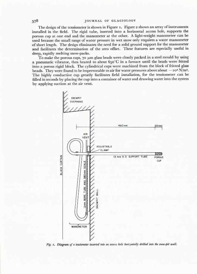
The design of the tensiometer is shown in Figure I. Figure 2 shows an array of instruments installed in the field. The rigid tube, inserted into a horizontal access hole, supports the porous cup at one end and the manometer at the other. A light-weight manometer can be used because the small range of water pressure in wet snow only requires a water manometer of short length. The design eliminates the need for a solid ground support for the manometer and facilitates the determination of the zero offset. These features are especially useful in deep, rapidly melting snow-packs.
To make the porous cups, 70 fJ-m glass beads were closely packed in a steel mould by using a pneumatic vibrator, then heated to about 650°C in a furnace until the beads were fritted into a porous rigid block. The cylindrical cups were machined from the block of fritted glass beads. They were found to be impermeable to air for water pressures above about - 104 N /m 2 •
The highly conductive cup greatly facilitates field installation, for the tensiometer can be filled in seconds by placing the cup into a container of water and drawing water into the system by applying suction at the air vent.
"" u « ..J CD
SNOWPIT
OVERHANG
ADJUSTABLE
CLAMP
..J
..J « ;;:
.Il. ;;: o 2 CJ)
460mm
13 mm O. D. SUPPORT TUBE
20mm
POROUS
CUP
Fig. I. Diagram of a tensiometer inserted into an access hole horizontally drilled into the snow-pit wall.

INSTRUMENTS AND METHODS 579
-- -It
jFig. 2 . A row oJ tensiometers installed in a melting snow-flack. One tetlsiometer in each group oJ jive is installed about 50 '1/1Il
higher than the others so that vertical pressure gradients can be measured. A metre stick is on the lower right ( (2 July 1974).
The transparent connec ting tubes consist of the 13 mm O .D. acrylic support tube, a Aexible Tygon tube, and short a ir- tight rubber connections. The manometer h a ngs from the
'support tube by means of a clamp. The water manometer is a glass capillary tube, wired to a scale. The large (2 ± 0.25 mm) bore of the capilla ry tube facilitates removal of air bubbles by means of a thin wire. This bore produces a capillary rise of ( 15 ± 2 mm) in the capillary tube, 'so 15 mm was subtracted from the manometer readings. T he tensiometers were installed into horizontally drilled access holes in the snow-pit wall. The wall was covered with polystyrene boards to reduce nocturna l radiation from the manometers a nd exposed connecting tubes.
T he use of a water m a nometer limits the response of the instrument to cha nges in snowwater pressure because of the time required for the manometer water to enter or leave the porous cup. The cup respo nse time tT has been defined to be 11 KQ (Richards, 1949), where K is the cup conductance, a nd Q is the gauge sensitivity. The gauge sensitivity is the pressure ·change (expressed as a head of water) per unit volume of water transferred to or from the tensiometer. For the ma nom eter that was used in the present study, the gauge sensitivity was
' 0.3 18 mm cha nge in mano meter reading per cubic millimetre of water transferred across the tensiometer cup. It was measured by immersing the porous cup in a container of water and timing the approach of the m a nometer reading he to its equilibrium value hI ; according to Klute and Gardner ( 1962) :
where ho is the initial manometer reading. T he tensiometers have cup response times in water ranging from 1.3 to 12 s with a median value of 3.0 s.
T he response time of a tensiometer to step changes in capillary pressure within a porous medium depends on whether the exchange of water between the porous medium and the cup 'is limited by the conductance of the cup, as above, or by that of the medium (Klu te and . Gardner, 1962). T he effect of the cup, given by Equation ( 2) , with a 3 s response time would

580 JO U RNA L OF GLACIOLOGY
result in the tensiometer r equiring 3.6 s to record 70 % of a step change in capillary pressure. When the conductivity of the porous m edium limits the tra nsfer of wa ter , the response for long cylindrical cups with an initial cup pressure ho suddenl y inserted into a porous medium with capillary pressure hi is given approximately by (Klute a nd Gardner, Ig62)
he- hi 1
ho- hi ~ 47TKQLt
in which K is the hydraulic conductivity of the medium (assumed consta nt during the tes t) and L is the length of the cup. Equation (3) is taken as a crude approxima tion for the response time for the stubby cups described in this report. For L = 20 mm, 70 % recovery will ta ke place in the same time (3.6 s) given by Equa tion ( 2 ) as long as K is 12 X 10- 6 m s- ' . For' gravity drainage in a steadil y melting sn ow-pack, K is equa l to the m elt rate. Hence at norma l m elt rates, the r esponse time would be limited by the snow conducta nce (Equation (3)) . For a higher percentage of recovery, the effect of flux on the recovery time is even more importa nt because of the m ore slowly varying time function in Equation (3) compared with tha t in Equation (2) . The times required for 70% response a re listed in Table I for different values of K .
T A BLE 1. TENSIOME T E R T IME LAG FOR 70 % RESP ONSE TO A
STEP C HANGE
Snow hy draulic
conductivity m s- J
10 X 10- 6
I X 10- 6
100 X 10- 9
1 0 X 10- 9
I X 10 - 9
Cup respollse in water by
E quation (2) and experiment
FIELD E RRORS IN TENSIOMETER MEASUR E MENTS
Estimate oJ snow respollse
Jrom Equation (3 )
4. 2
42 420
4 200
42000
T he snow-water pressure pw is given b y the equa tion:
pw = pwg(hM - hR+ hz),
where hM is the manom eter reading, hR is the capilla ry rise for the bore of the capillary tubing used in the m anometer (in the present case hR = 15 mm = 0.0 15 m ), hz is a zero offset, pw is the density of water ( I 000 kg/m3), and g is the acceleration due to gravity (g.8 m /s2) . In this equation , if the values of hM, h R, and Izz a re in millimetres, a factor of 10 - 3 a ppears on the righ thand side to give pw in newtons per square metre.
The zero offset is the height of the m a nom eter scale zero a bove the cylindrical axis of the cup. A zero offset is introduced to the extent tha t the tensiometer access hole is not drilled horizontally. The error can be system a tic if caused by defl ection of the drill by sloping ice shee ts ; on the other ha nd, ra ndom errors r esulting from lack of precision in levelling the drill during boring of the access hole will produce sta tistically a mean hz of zero . The standa rd devia tion of Izz for tensiom eter installa tion during the writers' experiments in ripe snow was measured to be cr = ± 8 mm .
When the fl ow ra te in the snow-pack was steady, the m a nometer readings were stead y to within the error in the m a nometer scale (± I mm). Progressive mel t-back of the snow-pit wall can result in bending of the exposed portion of the support tube under the weight of the manom eter while the rest of the tube is held firml y in the snow. Periodic m easurement of this " droop" allowed corrections to this time-va rying contribution to hz to within an error or cr = ±2 mm.

IN ST R U M EN T S AND MET HOD S
PR ESSU R E R ESPONSE TO DYED WATER INP UTS
The use of tensiometers in studying the downward melt-wa ter fl ow in snow is demonstrated in a n experiment conducted on 12 July 1974. A row of 25 tensiometers was installed in groups of 5 in a mel ting snow-pack of d ensity 580 kg /m 3 at a site 1 200 m a .s.l. on Mt Seymour in the Coast Mountains of British Columbia. For d emonstration purposes the snow surface was irrigated at m any times the normal melt rate. Rhodamine WT was diluted to a concen tration of abou t 1.5 X 10- 5 parts by weight and sprinkled over a n area of about I m X 3 m of the snow surface directly above the tensiometer array, at a rate of 20 X 10 - 6 m s- ' for about 300 s. Since a ll but one of the 25 tensiometers responded to the irrigation, it can be conclud ed that dye penetrated to a lmost a ll parts of the instrumented layer. The response of the tensiometers in the third and fourth groups (from the left in Figure 2) is shown in Figure 3. T he pressures shown are not corrected for a ny static zero error which probably
- 200
-4 00
w - 6 00 a: ::J <Jl <Jl W a: CL
5 -800 ~
~ I
~ o Z if>
-1000
-120 0
4 c IS AT 0.44 m DEPTH, THE OTHERS
ARE 0 .042 m LOWER . "} I--- 0 4b
'" 4c TENS IOMETERS x 4d
+ 4.
.~ -.~'~
/1) ~:---.
----___ 0 J $;
\ "'-1 f~ ,
'" ~ -:::::: ;t~+ ) X X
" X 0 -
-D. x-
~o, , 0 ....... '1-, 0
+- +
12 13 14 TIME (h . PST)
3b IS AT 0 .47m DEPTH, THE OT HERS
AR E 0.062 m LOWER . " } '" 3b
0 3c TENS IOMETER S x 3 d
+ 3.
.~~,,,, "'-----~ 0 ~'"
~~----=~. \,
~ r-- \ +- +f \x 1-, 0"
~ ~~--x +~ ....
~ .... jl ..... o ......... ~ ~ "+-+.,
\ "'-. ........ x
T
12 13 14 TIME (h . PSTl
Fig. 3. W ater-/Jressure changes i ll snow jollowing the application oj dyed water to the SIlOW surface between 13 .36 h and 13 .4I h Oil I2 July I974. These valnes arejor the third andjourth groups oj tensiometersjrom the lift oj Figure 2.
expla ins part of the scatter in the absolu te values among cups placed at the sam e level. Note that the range in arriva l times for the wetting fron ts and the range in the dra inage wave shapes are real since the zero error is constant with time. A fingering-type flow passed through the instrumen ted layer.
Also note that while the flux in the snow following drainage of the applied water would be expected to return to the origina l natural melt value, the snow water pressures are much lower afterwards. This would be expla ined by hysteres is in the hyd ra u lic conductivitycapillary pressure relation for snow, in common with other types of porous media. These details of water flow would not be revealed by melt pans which produce only a n integrated response in both space a nd time.
After dra inage of the applied pulse, a section of the snow was cut open to reveal the sta in pattern produ ced by d yed water retained by the snow. D etailed comparison of each tensiometer's pressur e curve a nd the dye patterns at tha t location is inconclusive, possibly because

JOURNAL OF GLA C IOLOGY
of the difficulty of localizing the cut section to better than a few centimetres of the vertical plan through the tensiometer cups. A fingering dye pattern characterizes the right three-quarters of the photograph (Fig. 4) .
Fig. 4. Dye-stain pattern in a cut section at I 5.00 h I2 July I971. The tensiometers had been removed and the CliP locatiolls tagged with beans prior to exposing the sectioll. Compare with Figure 3.
The general absence of " blurring" of the dye fingers in the photograph, taken over an hour after the pulse passed the tensiometer level, suggests that the dye has stained real structures with a larger permanent liquid-water content than that of the bulk of the snow-pack. In fact, cohesive yet permeable " glands" of icy appearance up to 10 mm in diameter were found in the same snow layer, 3.5 m away. The presence of a network of highly conducting glands could explain the fingering type of flow observed with the tensiometers.
The experiment was repeated on 30 July 1974 at another level in the snow-pack. The pressure curves in Figure 5 show the response of the middle two groups of tensiometers to the 8 min application of dyed water at a rate of 20 X 10 - 6 m S- I to the snow surface. This time the tensiometers in each group responded similarly in respect to arrival times and drainage wave shapes although differences remained between the different groups. The similar response among tensiometers in each group indicates the absence of fingering-type flow at this level. The resultant dye-stain pattern shown in Figure 6 suggests concentrations of the flow into zones about 500 mm across within which the flow is uniform and vertically directed. This concentration is thought to be produced by the ice sheets at the top of the section.
SUMMARY
The use of a tensiometer in a snow-pack requires special attention to the following four points: First, the tensiometer must be used only in a wet snow-pack and care must be taken to prevent freezing of the exposed manometer. Secondly, the height of the porous cup relative to the manometer scale zero (the zero offset) should be accurately known, a task made more difficult by melting of the snow surface and snow-pit walls. Third, the lateral variation in flow

~
E "z
- 200
- 400
W -600 Il: :::J V> V> W Il: fi-
ll: ~ - 800 .. ~ I ~ o z '"
-1000
-1200
4 ~
-
12
IN ST R UMENTS AND METHODS
IS AT 0 .39m DEPTH, THE OTHERS I
ARE 0.0 43m LOWER 3b IS AT 0 .38m DEPTH, THE OTHERS . '" } ARE 0 .0 45m LOWER
0 4b t:. 4 c TEN SIOMETERS A •
'"} x 4d J I> 3b
+ 4. 0 3c TE NSIOMETER S + V'j \~ x 3d
\ '+"'t- + 3. S ><,. x- x4 f' ~"
x x
!.::~ ~ ? +-0 - 006
- /'
I>?\'" "
.. - .. ...
13 14 12 13 14 TIME (h . PST) TIME (h . PST)
Fig. 5. Water-pressure changes in snow following the applicatioll qf dyed water to the snow surface between I3.47 It alld I3.55 It on 30 J uly I974. The values are for the celttre groups of tensiometers located by holes ill Figure 6.
'.~ ./ I ;If
J.' ... t 1 . . ·f , I
~ ' I
Fig. 6. Dye-stain p attern ill a cut section at I S .OO h 30 July I974. A metre stick is on the left. The lysimeters located below the line of tensiometer holes were used to measure flux.

JO URNAL OF GLAC IO LO GY
requires the use of ma ny tensiometers if the mean snow-water pressure of a layer is required . Finally, short-wave radiation penetrating the snow from the access snow-pit must be minimized so as to produce an insignificant change in snow properties in the vicinity of the porous cup.
Tensiometers can b e used in the field to reveal the flow pattern and the water-pressure response of snow to inputs of water at the surface. The instruments are light in weight and can be installed within minutes into a snow-pit wall. Snow-melt events can be monitored by their pressure effects. L a rge numbers of these inexp ensive instruments can be deployed to invc:s tigate the effects of vegetation cover, topography, and ice sheets on m elt rate and run-off. T ensiometers could be used to determine the extent of fingering-type flow at norma l melt rates within snow-packs a nd their effect on melt-wave travel times. An interesting research need is to defin e the relation between snow water pressure and snow-melt rate.
A CKNOWLEDGEMENTS
This work was carried out as part of the first a uthor 's Ph.D. dissertation research at the University of British Columbia. Grants from the President's Research Fund and the H. R . MacMillan family a re gratefully acknowledged as well as the assistance offered by Drs Michael Church, Lien C how, and Narendar Nagpal.
MS. received I 6 November 1977 and in revised form 2 1 Deamber I977
REFERE NCES
Col beck, S. C. 1976. On the use of tensiometers in snow hydrology. J ournal of Gtaciology, Vol. [ 7, No. 75, p. [35-40 .
Klute, A., and Gardner, W . R . [962. T ensiometer response time. Soil Science, Vol. 93, No. 3, p. 204- 07_ Richards, L. A. [949. M ethods of measuring soil moisture tension. Soil Science, Vol. 68, No. I , p. 95- [ [ 2 .
Richards, S.]. [965. Soil suction measurements with tensiometers. (In Black, C. A., ed. M ethods of soil analysis. Pt. I. Physical alld mineralogical properties, including statistics of measurement and sampling. Madison, Wisconsin, American Society of Agronomy, p. [53-63. (Agronomy Series, M onograph No. 9. »
Wankiewicz, A. C. Unpublished. Water percolation within a d eep snowpack- field investigations at a site on Mt. Seymour, British Columbia. [Ph.D. thesis, University of British Columbia, [ 976.]