vol ii tech spec aiims
DESCRIPTION
ljrter krjthrhtrk ohegthriew tp p oweirjgtwer p oipgjiertjugoiwuq[thweoituj [oirutopiweurp[ti [pni[poupo[ewritpewrip[tnw ui[puryp[twierp n niTRANSCRIPT
TENDER DOCUMENTS
FOR
Construction of 33kV Line from 132/33kV Ransinghpur
OPTCL Grid Substation to AIIMS at Bhubaneswar, Odisha
Volume – II
Technical Bid
CENTRAL ELECTRICITY SUPPLY UTILITY OF ORISSA (CESU)
IDCO POLE, 2nd Floor, Janpath, Bhubaneswar-751022
TELEPHONE: (0674) - 2542895, 2545681, 2541727
FAX: 0674 – 2543125
Tender Specification for Construction of 33kV line for AIIMS, Bhubaneswar, CESU/Orissa
Central Electricity Supply Utility of Orissa Page 2
CENTRAL ELECTRICITY SUPPLY UTILITY OF ORISSA
(CESU) Head Office: IDCO POLE, 2nd Floor, Janpath, Bhubaneswar-751022
TELEPHONE: (0674) - 2542895, 2545681, 2541727
FAX: 0674 – 2543125
BID ENQUIRY NO:CESU.H.Qrs. / P&S /523/12-13/24764 / Dt. 30.07.2012
BIDDING DOCUMENTS

Tender Specification for Construction of 33kV line for AIIMS, Bhubaneswar, CESU/Orissa
Central Electricity Supply Utility of Orissa Page 3
BID DOCUMENTS CONSIST OF THE FOLLOWING VOLUMES
VOLUME- I (COMMERCIAL REQUIREMENTS)
1. Section – I :-Invitation For Bids - IFB
2. Section – II :-General Terms and Conditions
of the Contract - GTCC
3. Section – III :-Price Schedule Format - PSF
4. Section – IV :-BID Proposal Letter - BPL
5. Section – V :-ANNEXURE - ANNEX
VOLUME-II (TECHNICAL REQUIREMENTS)
1. Section – I :-General
2. Section – II :- 33KV Conductor
3. Section – III :- R.S Joist Pole
4. Section – IV :- Insulators & hardware fittings
5. Section – V :- 33 kV Isolator with earth switch
6. Section – VI :- Lightning Arrestor
7. Section – VII :- 33kV UG Cable
8. Section – VIII :- HT cable joints and terminals
9. Section – IX :- Cable Laying Methodology
10. Section – X :- Proposed Route Map
VOLUME- III (BID PROPOSAL SHEETS)
1. PART – A :-ABSTRACT OF PRICE SCHEDULE SHEETS
2. PART – B :- PRICE SCHEDULE SHEETS

Tender Specification for Construction of 33kV line for AIIMS, Bhubaneswar, CESU/Orissa
Central Electricity Supply Utility of Orissa Page 4
Section-I
General
Tender Specification for Construction of 33kV line for AIIMS, Bhubaneswar, CESU/Orissa
Central Electricity Supply Utility of Orissa Page 5
1.0. INTRODUCTION:
The CENTRAL ELECTRICITY SUPPLY UTILITY OF ORISSA,
Hereinafter called CESU/OWNER is inviting Bids in respect of Total Turnkey Package for
Construction of 33 kV line from Ransinghpur (OPTCL) S/S to AIIMS, Bhubaneswar, Orissa on
total turnkey basis including supply of all Equipments/Materials Erection (including Civil Works),
Testing and Commissioning as per the Scope detailed in the Bid Documents.
2.0. NATURE OF WORK:
The work covered by this Specification is for 33kV distribution lines as specified herein and in the
attached Schedules. The Underground distribution lines will form a part of the CESU’s distribution
System.
3.0. SCOPE:
Construction of 33 kV Line Using 232 mm², ACSR Panther conductor and 33KV, XLPE, UG
Cable by using 3x400mm² (Double circuit with spare) and 3x300mm²(Single circuit with spare)
Cable from Ransinghpur (OPTCL) S/S to AIIMS, Bhubaneswar. This 33kV line is through a
combination of overhead and underground lines.
The work Involves: a) Construction of 33kV line from 132/33kV Ransinghpur grid S/S to AIIMS at
Bhubaneswar.
b) Stringing of 33KV, 232 mm², ACSR Panther conductor for a circuit length of 0.09 kM.
(0.045 x 2ckt.).
c) Erection of Insulators & hardware fittings for 33kV line.
d) Construction of DP structure (3nos) with required Insulators and H/W fittings.
e) Construction of 6-Pole structure (1no) with one metering arrangement and required
Insulators and H/W fittings.
f) Construction of foundation (Civil Work) for the 6 poles structure and DPs.
g) Erection of 33 kV Double Break Isolator with earth switches 3nos for DP structure and
5nos for 6-Pole Structure.
h) Erection of 33 kV Lightning Arrestors for DP & 6-Pole structure (21 nos).
i) Laying of 400sq mm, 33KV, 3core XLPE UG Cable (Double Circuit with Spare) up to 6
pole structure inside the medical complex through Open trench method.
(420x2=840mtrs., with spare).
j) Laying of 300sq mm, 33KV, 3core XLPE UG Cable From 6 pole structure to residential
complex through Open trench method. (500mtrs., with spare)
k) 33KV, XLPE Cable Jointing kits (3 core/ 3 phase) for 400 mm² (8nos) and 300 mm²
(4nos).
l) Earthing Device having 40mm diameter and, 3Mtr Length for DP Structure, 6-Pole
structure, 400 mm² and 300 mm² ,33KV, XLPE Cable (22 nos).

Tender Specification for Construction of 33kV line for AIIMS, Bhubaneswar, CESU/Orissa
Central Electricity Supply Utility of Orissa Page 6
3.1 Bill of Quantities (BOQ):
Bill Of Material For Construction of 33 kV line from Ransinghpur (OPTCL) S/S to AIIMS, Bhubaneswar, Odisha
on Total Turn Key basis
Sl No Description Of Item Unit Quantity
1 Supply of materials for Construction of 33KV Line DP structure with DB Isolator arrangement
(2+1)nos.
150 X 150 mm RS joist (10 Mtr) (for 3 nos of DP
structure) (6 Nos poles) Kg 2076
100 X 50 X 6 mm MS channel Kg 720
65 X 65 X 6 mm MS angle Kg 225
HT stay set (For 2nos of DPs) No 4
GI Stay wire (7/8) (For 2nos of DPs) Kg 60
HT stay insulator (For 2nos of DPs) No 4
HT stay clamp (Each 1.95Kg) (4 Pairs) (For 2nos of
DPs) Kg 7.8
33KV Lightening Arrestor (33KV, 10KA) No 9
33KV DB Isolater with earth switch set 3
Earthing Device (40mm Dia, 3Mtr Length) No 6
Earthing Complete with Supply of Charcoal salt etc.
(Excluding earthing device) No 6
50 X 6mm GI Flat or earthing (4 Nos) Kg 160
Aluminium binding wire/ tape Kg 6
Assorted size Nuts & Bolts Kg 60
Concreting of pole pits No 6
Cooping of pole pits No 6
Concreting of Stay(For 2nos of DPs) No 4
Red Oxide Paint Ltr 15
Aluminium Paint Ltr 15
Black Paint Ltr 4
Tender Specification for Construction of 33kV line for AIIMS, Bhubaneswar, CESU/Orissa
Central Electricity Supply Utility of Orissa Page 7
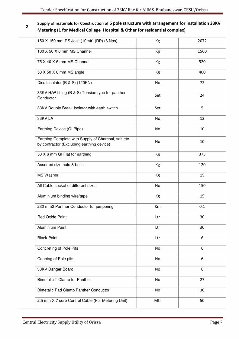
2 Supply of materials for Construction of 6 pole structure with arrangement for installation 33KV
Metering (1 for Medical College Hospital & Other for residential complex)
150 X 150 mm RS Joist (10mtr) (DP) (6 Nos) Kg 2072
100 X 50 X 6 mm MS Channel Kg 1560
75 X 40 X 6 mm MS Channel Kg 520
50 X 50 X 6 mm MS angle Kg 400
Disc Insulater (B & S) (120KN) No 72
33KV H/W fitting (B & S) Tension type for panther
Conductor Set 24
33KV Double Break Isolator with earth switch Set 5
33KV LA No 12
Earthing Device (GI Pipe) No 10
Earthing Complete with Supply of Charcoal, salt etc.
by contractor (Excluding earthing device) No 10
50 X 6 mm GI Flat for earthing Kg 375
Assorted size nuts & bolts Kg 120
MS Washer Kg 15
All Cable socket of different sizes No 150
Aluminium binding wire/tape Kg 15
232 mm2 Panther Conductor for jumpering Km 0.1
Red Oxide Paint Ltr 30
Aluminium Paint Ltr 30
Black Paint Ltr 6
Concreting of Pole Pits No 6
Cooping of Pole pits No 6
33KV Danger Board No 6
Bimetalic T Clamp for Panther No 27
Bimetalic Pad Clamp Panther Conductor No 30
2.5 mm X 7 core Control Cable (For Metering Unit) Mtr 50
Tender Specification for Construction of 33kV line for AIIMS, Bhubaneswar, CESU/Orissa
Central Electricity Supply Utility of Orissa Page 8
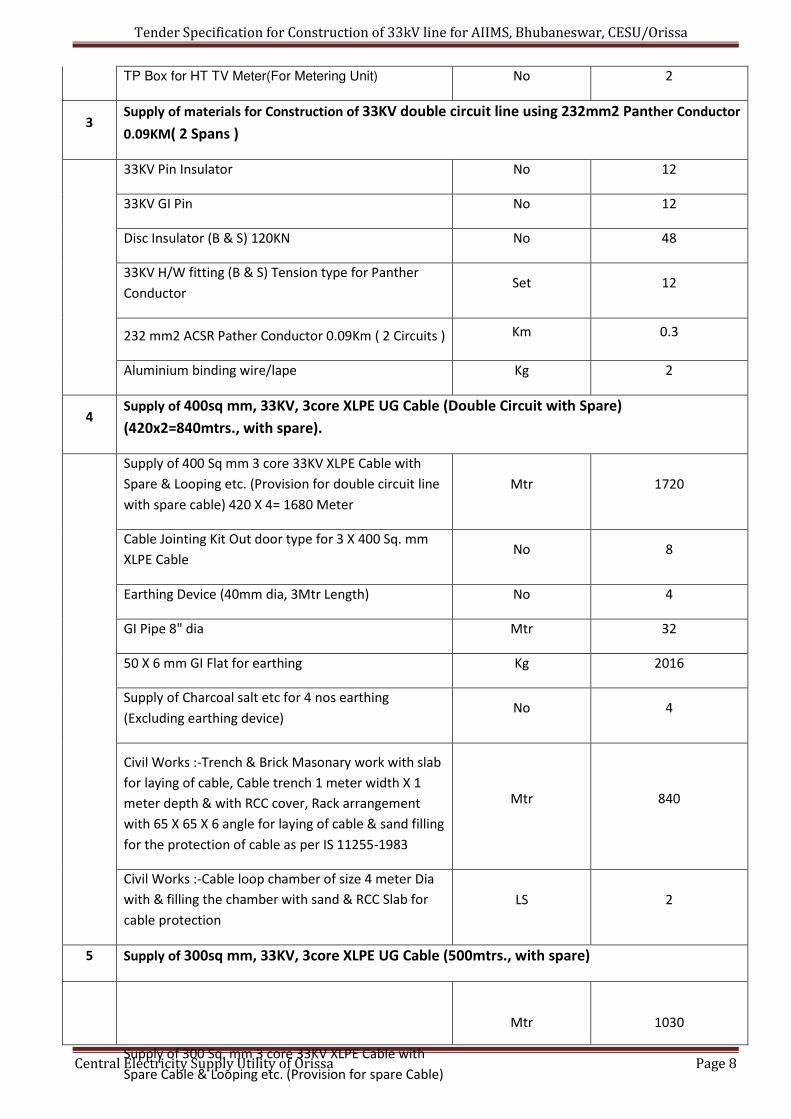
TP Box for HT TV Meter(For Metering Unit) No 2
3 Supply of materials for Construction of 33KV double circuit line using 232mm2 Panther Conductor
0.09KM( 2 Spans )
33KV Pin Insulator No 12
33KV GI Pin No 12
Disc Insulator (B & S) 120KN No 48
33KV H/W fitting (B & S) Tension type for Panther
Conductor Set 12
232 mm2 ACSR Pather Conductor 0.09Km ( 2 Circuits ) Km 0.3
Aluminium binding wire/lape Kg 2
4 Supply of 400sq mm, 33KV, 3core XLPE UG Cable (Double Circuit with Spare)
(420x2=840mtrs., with spare).
Supply of 400 Sq mm 3 core 33KV XLPE Cable with
Spare & Looping etc. (Provision for double circuit line
with spare cable) 420 X 4= 1680 Meter
Mtr 1720
Cable Jointing Kit Out door type for 3 X 400 Sq. mm
XLPE Cable No 8
Earthing Device (40mm dia, 3Mtr Length) No 4
GI Pipe 8" dia Mtr 32
50 X 6 mm GI Flat for earthing Kg 2016
Supply of Charcoal salt etc for 4 nos earthing
(Excluding earthing device) No 4
Civil Works :-Trench & Brick Masonary work with slab
for laying of cable, Cable trench 1 meter width X 1
meter depth & with RCC cover, Rack arrangement
with 65 X 65 X 6 angle for laying of cable & sand filling
for the protection of cable as per IS 11255-1983
Mtr 840
Civil Works :-Cable loop chamber of size 4 meter Dia
with & filling the chamber with sand & RCC Slab for
cable protection
LS 2
5 Supply of 300sq mm, 33KV, 3core XLPE UG Cable (500mtrs., with spare)
Supply of 300 Sq. mm 3 core 33KV XLPE Cable with
Spare Cable & Looping etc. (Provision for spare Cable)
Mtr 1030
Tender Specification for Construction of 33kV line for AIIMS, Bhubaneswar, CESU/Orissa
Central Electricity Supply Utility of Orissa Page 9
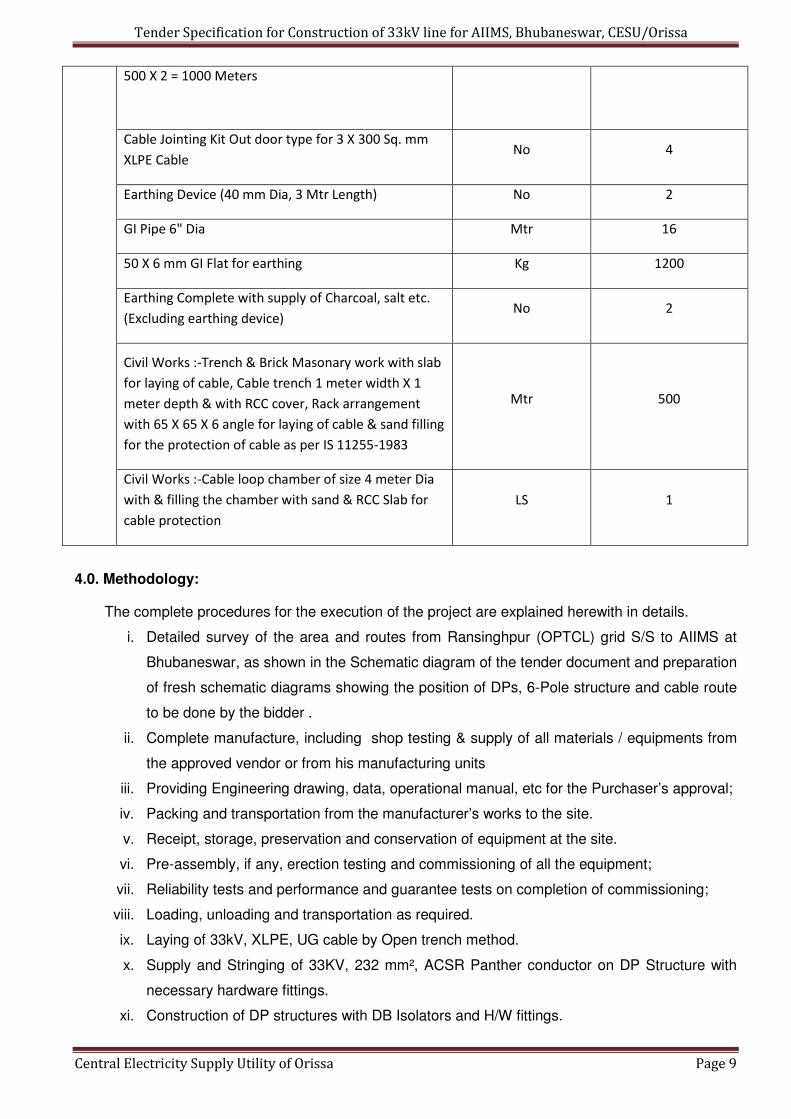
500 X 2 = 1000 Meters
Cable Jointing Kit Out door type for 3 X 300 Sq. mm
XLPE Cable No 4
Earthing Device (40 mm Dia, 3 Mtr Length) No 2
GI Pipe 6" Dia Mtr 16
50 X 6 mm GI Flat for earthing Kg 1200
Earthing Complete with supply of Charcoal, salt etc.
(Excluding earthing device) No 2
Civil Works :-Trench & Brick Masonary work with slab
for laying of cable, Cable trench 1 meter width X 1
meter depth & with RCC cover, Rack arrangement
with 65 X 65 X 6 angle for laying of cable & sand filling
for the protection of cable as per IS 11255-1983
Mtr 500
Civil Works :-Cable loop chamber of size 4 meter Dia
with & filling the chamber with sand & RCC Slab for
cable protection
LS 1
4.0. Methodology:
The complete procedures for the execution of the project are explained herewith in details.
i. Detailed survey of the area and routes from Ransinghpur (OPTCL) grid S/S to AIIMS at
Bhubaneswar, as shown in the Schematic diagram of the tender document and preparation
of fresh schematic diagrams showing the position of DPs, 6-Pole structure and cable route
to be done by the bidder .
ii. Complete manufacture, including shop testing & supply of all materials / equipments from
the approved vendor or from his manufacturing units
iii. Providing Engineering drawing, data, operational manual, etc for the Purchaser’s approval;
iv. Packing and transportation from the manufacturer’s works to the site.
v. Receipt, storage, preservation and conservation of equipment at the site.
vi. Pre-assembly, if any, erection testing and commissioning of all the equipment;
vii. Reliability tests and performance and guarantee tests on completion of commissioning;
viii. Loading, unloading and transportation as required.
ix. Laying of 33kV, XLPE, UG cable by Open trench method.
x. Supply and Stringing of 33KV, 232 mm², ACSR Panther conductor on DP Structure with
necessary hardware fittings.
xi. Construction of DP structures with DB Isolators and H/W fittings.
Tender Specification for Construction of 33kV line for AIIMS, Bhubaneswar, CESU/Orissa
Central Electricity Supply Utility of Orissa Page 10
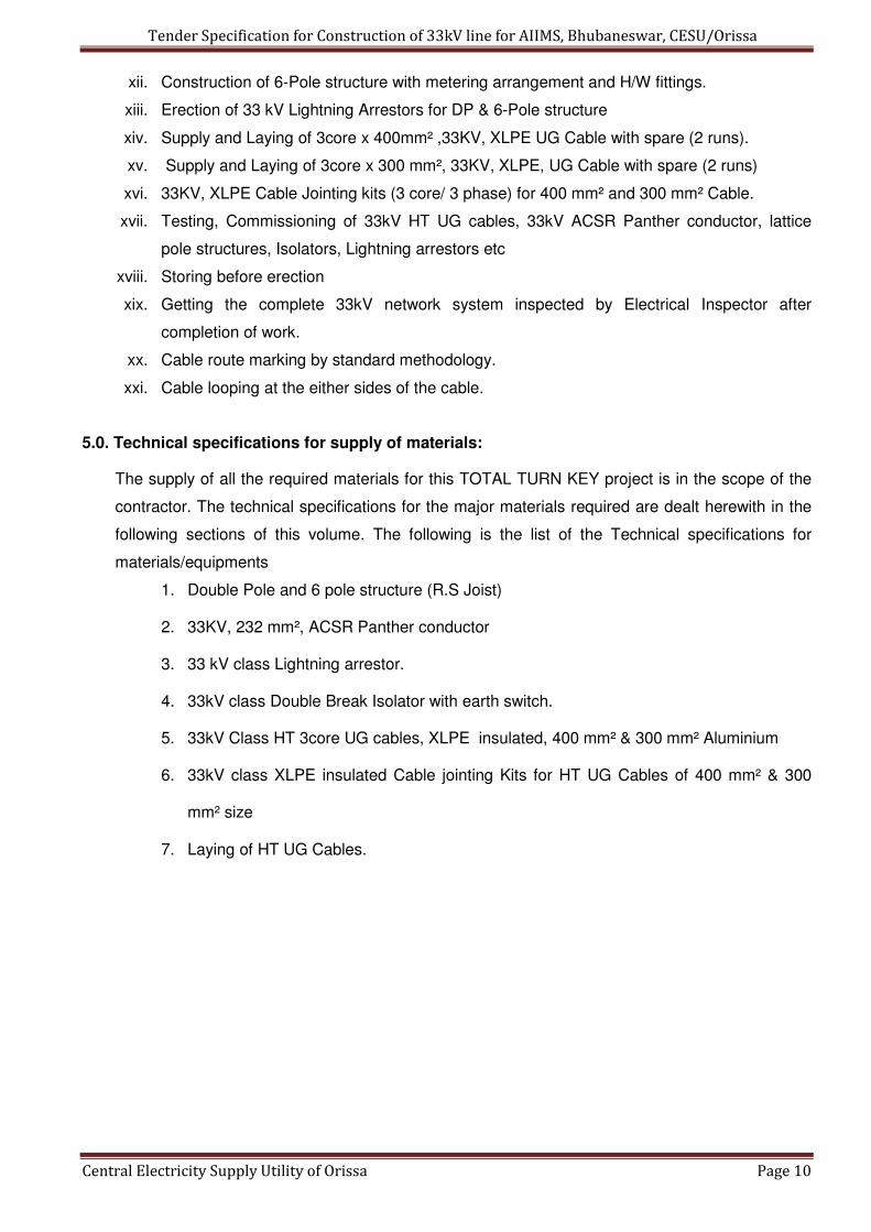
xii. Construction of 6-Pole structure with metering arrangement and H/W fittings.
xiii. Erection of 33 kV Lightning Arrestors for DP & 6-Pole structure
xiv. Supply and Laying of 3core x 400mm² ,33KV, XLPE UG Cable with spare (2 runs).
xv. Supply and Laying of 3core x 300 mm², 33KV, XLPE, UG Cable with spare (2 runs)
xvi. 33KV, XLPE Cable Jointing kits (3 core/ 3 phase) for 400 mm² and 300 mm² Cable.
xvii. Testing, Commissioning of 33kV HT UG cables, 33kV ACSR Panther conductor, lattice
pole structures, Isolators, Lightning arrestors etc
xviii. Storing before erection
xix. Getting the complete 33kV network system inspected by Electrical Inspector after
completion of work.
xx. Cable route marking by standard methodology.
xxi. Cable looping at the either sides of the cable.
5.0. Technical specifications for supply of materials:
The supply of all the required materials for this TOTAL TURN KEY project is in the scope of the
contractor. The technical specifications for the major materials required are dealt herewith in the
following sections of this volume. The following is the list of the Technical specifications for
materials/equipments
1. Double Pole and 6 pole structure (R.S Joist)
2. 33KV, 232 mm², ACSR Panther conductor
3. 33 kV class Lightning arrestor.
4. 33kV class Double Break Isolator with earth switch.
5. 33kV Class HT 3core UG cables, XLPE insulated, 400 mm² & 300 mm² Aluminium
6. 33kV class XLPE insulated Cable jointing Kits for HT UG Cables of 400 mm² & 300
mm² size
7. Laying of HT UG Cables.
Tender Specification for Construction of 33kV line for AIIMS, Bhubaneswar, CESU/Orissa
Central Electricity Supply Utility of Orissa Page 11
Section-II
33kV Conductor

Tender Specification for Construction of 33kV line for AIIMS, Bhubaneswar, CESU/Orissa
Central Electricity Supply Utility of Orissa Page 12
TECHNICAL SPECIFICATION FOR 33kV ACSR Panther Conductor
1.0 SCOPE
This section covers design, manufacture, testing before dispatch, packing, supply and
delivery F.O.R destination of 0.3kMs of "PANTHER" ACSR Conductor of size 232mm².
2.0 STANDARDS 2.1 The Conductor shall also comply in all respects with the IS:398 (Part-II) 1996 with latest
amendments unless otherwise stipulated in this specification or any other International
Standards which ensure equal or higher quality material.
2.2 The ACSR Conductor shall also conform to the following standards
Sr.
No.
Indian
Standards Title
International
Standards
1 IS : 209 Specification BS : 3436 for zinc
2
IS : 398 Part
I to V As
relevant)
Specification IEC : 209 for aluminum BS :
215 conductor for (Part-II) overhead Transmission purpose.
3 IS : 1778 Reels and BS : 1559 Drums for Bare
Conductors
4 IS : 1521 Method of Ten-ISO / R 89 site testing of
Steel wire.
5 IS : 2629 Recommended practice for Hot dip galvanising of Iron
and Steel.
6 IS : 2633 Method of Testing uniformity of coating of
zinc coated articles.
7 IS : 4826 Galvanised coating quoting on round steel
wire.
ASTM A – 472 729 BS : 443
8 IS : 6745 Methods of determination of weight of zinc coating of
zinc coated iron and steel articles. BS : 443
9 IS : 8263 Method of radio Interference tests on high
voltage Insulators
IEC:437 NEMA : 107 CISPR
10 IS : 1841 EC grade aluminum rod produced by rolling
(Second Revision)
11 IS : 5484 EC grade aluminum rod produced by continuous
casting and rolling (first revision)
2.3 However, in an event where the supplier offers ACSR conductor conforming to standards
other than the above, then the salient points of comparison between the standards
adopted and the standards quoted herein shall be detailed in relevant schedule with an
authenticated English version of such standards referred to.

Tender Specification for Construction of 33kV line for AIIMS, Bhubaneswar, CESU/Orissa
Central Electricity Supply Utility of Orissa Page 13
3.0 GENERAL TECHNICAL REQUIREMENTS
The General Technical Requirements are given in Clause-31.0. The Conductor shall conform
to these technical requirements.
3.1 MATERIALS/WORKMANSHIP
3.1.1 The material offered shall be of best quality and workmanship. The steel cored aluminum
conductor strands shall consist of hard drawn aluminum wire manufactured from not less
than 99.5% pure electrolytic aluminum rods of E.C. grade and copper content not exceeding
0.04%. They shall have the same properties and characteristics as prescribed in IEC:889-
1987. The steel wire shall be made from material produced either by the acid or basic open
hearth process or by electric furnace process or basic oxygen process. Steel wire drawn from
Bessemer Process shall not be used.
3.1.2 The steel wires shall be evenly and uniformly coated with electrolytic high grade, 99.95%
purity zinc complying with the latest issue of IS-209 for zinc. The uniformity of zinc coating
and the weight of coating shall be in accordance with standard specification and shall be
tested and determined according to the latest IS-2633 or any other authoritative standard.
3.1.3 The steel strands shall be hot dip galvanized and shall have a minimum zinc coating of 250
gm/Sq.m after stranding. The coating shall be smooth, continuous, and of uniform thickness,
free from imperfections and shall withstand minimum three dips after stranding in standard
preece test. The steel strands shall be preformed and post formed in order to prevent
spreading of strands in the event of cutting of composite core wire. The properties and
characteristics of finished strands and individual wires shall be as prescribed in IEC:888-
1987.
4.0 CONDUCTOR PARAMETERS
4.1 The Parameters of individual strands and composite steel cored aluminum conductor shall be
in accordance with the standard specification values.
4.2 Creep in a conductor is attributed partly due to settlement of strands and partly due to non-
elastic elongation of metal when subjected to load. The manufacturer of conductor shall
furnish the amount of creep which will take place in 10, 20, 30, 40 and 50 years along with
the supporting calculations. The calculations should be based on everyday temperature of
32 ºC and everyday tension of 25% of UTS of conductor of 33 KV Lines.
5.0 TOLERANCES 5.1 The tolerances on standard diameter of Aluminum and Steel wires shall be as detailed in
specific technical requirements.
5.2 The cross-section of any wire shall not depart from circularity by more than an amount
corresponding to the tolerance on the standard diameter.
5.3 The details of diameters, lay ratios of Aluminum and steel wires shall be in accordance with
the standard specification.

Tender Specification for Construction of 33kV line for AIIMS, Bhubaneswar, CESU/Orissa
Central Electricity Supply Utility of Orissa Page 14
6.0 SURFACE CONDITIONS
6.1 All aluminum and steel strands shall be smooth, and free from all imperfections, spills/and
splits. The finished conductor shall be smooth, compact, uniform and free from all
imperfections including spills and splits, die marks, scratches, abrasions, scuff marks, kinks
(protrusion of wires), dents, pressmarks, cut marks, wire cross-over, over-riding looseness,
pressure and/or unusual bangle noise on tapping, material inclusions, white rust, powder
formation or black spots (on account of reaction with trapped rain water etc.,), dirt, grit, etc.
The surface of conductor shall be free from points, sharp edges, abrasions or other
departures from smoothness or uniformity of surface contour that would increase radio
interference and corona losses. When subjected to tension upto 50% of the ultimate strength
of the conductor, the surface shall not depart from the cylindrical form or any part of the
component parts or strands move relative to each other in such a way as to get out of
placeand disturb the longitudinal smoothness of the conductor.
7.0 JOINTS IN WIRES
7.1 Aluminium wires
7.1.1 During stranding, no aluminium wire welds shall be made for the purpose of achieving the
required conductor length.
7.1.2 No joint shall be permitted in the individual aluminium wires in the outer most layer of the
finished Conductor. However, joints in the 12 wire & 18 wire inner layer of the conductor are
permitted but these joints shall be made by the cold pressure butt welding and shall be such
that no two such joints shall be within 15 meters of each other in the complete stranded
conductor.
7.2 Steel wires
There shall be no joints in finished steel wires forming the core of the steel reinforced
aluminum conductor.
8.0 STRANDING
8.1 The wires used in construction of the stranded conductor, shall, before stranding, satisfy all
requirements of IS-398 (Part-II) 1996.
8.2 In all constructions, the successive layers shall be stranded in opposite directions. The
wires in each layer shall be evenly and closely stranded round the underlying wire or
wires. The outer most layer of wires shall have a right hand lay. The lay ratio of the different
layers shall be within the limits as per standard specification.
9.0 PACKING
9.1 The conductor shall be supplied in non-returnable strong wooden drums provided with lagging
of adequate strength constructed to protect the conductor against any damage and
displacement during transit, storage and subsequent handling and stringing operations in the
field. The drums shall generally conform to IS-1778-1980 and latest version except as

Tender Specification for Construction of 33kV line for AIIMS, Bhubaneswar, CESU/Orissa
Central Electricity Supply Utility of Orissa Page 15
otherwise specified hereinafter. The conductor drums shall be adequate to wind one
standard length of 2500 meters PANTHER ACSR conductor.
9.2 The drums shall be suitable for wheel mounting and for letting off the conductor under a
minimum controlled tension of the order of 5KN. The conductor drums shall be provided with
necessary clamping arrangements so as to be suitable for tension stringing of power
conductor.
9.3 The bidders should submit their drawings of the conductor drums along with the bid. After
placement of letter of intent the supplier shall submit four copies of fully dimensioned
drawing of the drum for purchaser's approval. After getting approval from the purchaser,
supplier shall submit 30 more copies of the approved drawings for further distribution and
field use at Board's end.
9.4 All wooden components shall be manufactured out of seasoned soft wood free from
defects that may materially weaken the component parts of the drums. Preservative
treatment for anti-termite/anti fungus shall be applied to the entire drum with preservatives of
a quality which is not harmful to the conductor.
9.5 All flanges shall be 2-ply construction with 64 mm thickness. Each ply shall be nailed and
clenched together at approximately 90 degrees. Nails shall be driven from the inside face of
the flange, punched and then clenched on the outer face. Flange boards shall not be less
than the nominal thickness by more than 2 mm. There shall not be less than 2 nails per board
in each circle.
9.6 The wooden battens used for making the barrel of the conductor shall be of segmental type.
These shall be nailed to the barrel supports with at least two nails. The battens shall be
closely butted and shall provide a round barrel with smooth external surface. The edges of
the battens shall be rounded or chamfered to avoid damage to the conductor.
9.7 Barrel studs shall be used for construction of drums. The flanges shall be holed and the barrel
supports slotted to receive them. The barrel studs shall be threaded over a length on either
end, sufficient to accommodate washers, spindle plates and nuts for fixing flanges at the
required spacing.
9.8 Normally, the nuts on the studs shall stand protruded of the flanges. All the nails used on the
inner surface of the flanges and the drum barrel shall be countersunk. The ends of the barrel
shall generally be flushed with the top of the nuts.
9.9 The inner cheek of the flanges and drum barrel surface shall be painted with bitumin
based paint.
9.10 Before reeling, card board or double corrugated or thick bituminised waterproof bamboo paper
shall be secured to the drum barrel and inside of flanges of the drum by means of a suitable
commercial adhesive material. The paper should be dried before use. Medium grade kraft
paper shall be used in between the layers of the conductor. After reeling the conductor the
exposed surface of the outer layer of conductor shall be wrapped with thin polythene sheet
across the flanges to preserve the conductor from dirt, grit and damage during transportation

Tender Specification for Construction of 33kV line for AIIMS, Bhubaneswar, CESU/Orissa
Central Electricity Supply Utility of Orissa Page 16
and handling and also to prevent ingress of rain water during storage/transport.
9.11 A minimum space of 75 mm shall be provided between the inner surface of the external
protective lagging and outer layer of the conductor. Outside the protective lagging, there shall
be minimum of two binders consisting of hoop iron/galvanized steel wire. Each protective
lagging shall have two recesses to accommodate the binders.
9.12 Each batten shall be securely nailed across grains as far as possible to the flange edges with
atleast 2 nails per end. The length of the nails shall not be less than twice the thickness of
the battens. The nail shall not protrude above the general surface and shall not have
exposed sharp edges or allow the battens to be released due to corrosion.
9.13 The conductor ends shall be properly sealed and secured with the help of U-nails on one side
of the flanges.
9.14 Only one standard length of conductor shall be wound on each drum. The method of lagging
to be employed shall be clearly stated in the tender.
9.15 As an alternative to wooden drum Bidder may also supply the conductors in non- returnable
painted steel drums. The painting shall conform to IS:9954-1981,reaffirmed in 1992. Wooden/
steel drum will be treated at par for evaluation purpose and accordingly the Bidder should
quote the package.
10.0 LABELLING AND MARKING
10.1 The drum number shall be branded or gauged or stenciled into the flange. An arrow shall be
marked on the sides of the drum, together with the words "Roll this way". Each drum shall
have the following information provided on the outside of the flange stenciled with indelible
ink.
a) Manufacturer's name and address.
b) Contract/Specification number.
c) Size and type of conductor.
d) Net weight of the conductor.
e) Gross weight of the conductor and drum.
f) Length of the conductor.
g) Position of the conductor end.
h) Drum and lot number.
i) Name and address of the consignee.
j) Month and year of manufacture.
k) The drum may also be marked with standard specification as per which the conductor is
manufactured.
11.1 STANDARD LENGTHS
11.1 The standard length of the conductor shall be 2500 metres. Bidder shall indicate the standard
length of the conductor to be offered by them. A tolerance of plus or minus 5% on the

Tender Specification for Construction of 33kV line for AIIMS, Bhubaneswar, CESU/Orissa
Central Electricity Supply Utility of Orissa Page 17
standard length offered by the bidder shall be permitted. All lengths outside this limit of
tolerance shall be treated as random lengths.
11.2 Random lengths will be accepted provided no length is less than 70% of the standard length
and total quantity of such random length shall not be more than 10% of the total quantity
order. When one number random length has been manufactured at any time, five (5) more
individual lengths, each equivalent to the above random length with a tolerance of +/-5% shall
also be manufactured and all above six random lengths shall be dispatched in the same
shipment. At any point, the cumulative quantity supplied including such random lengths shall
not be more than 12.5% of the total cumulative quantity supplied including such random
lengths. However, the last 20% of the quantity ordered shall be supplied only in standard
length as specified.
11.3 Bidder shall also indicate the maximum single length, above the standard length, he can
manufacture in the guaranteed technical particulars of offer. This is required for special
stretches like river crossing etc. The Purchaser reserves the right to place orders for the
above lengths on the same terms and conditions applicable for the standard lengths during
the pendency of the Contract.
12.0 QUALITY ASSURANCE PLAN
A Quality Assurance Plan including customer hold points covering the manufacturing
activities of the material shall be required to be submitted by the tenderer to the purchaser
along with the tender. The Quality Assurance Plan after the same is found acceptable, will
be approved by the purchaser.The contractor shall follow the approved Quality Assurance
Plan in true spirit. If desired by the purchaser, he shall give access to all the documents and
materials to satisfy the purchaser that the Quality Assurance Plan is being properly followed.
13.0 TESTING
13.1 SELECTION OF TEST SAMPLES FOR TYPE TESTS
13.1.1 The samples shall be taken from a continuous length of conductor and subjected to all the
tests specified in clause 14.
13.2 SELECTION OF TEST SAMPLES FOR ACCEPTANCE TESTS
13.2.1 Before dispatch from the works individual wire and finished steel cored aluminum
conductor shall be subjected to the tests as specified in IS:398 or any other
authoritative standard.
13.2.2 Sample for individual wires for test shall be taken before stranding from outer ends of not
less than ten per cent of the spools in the case of aluminium wire and ten per cent of the wire
coils in the case of steel wires. If samples are taken after stranding, they shall be obtained by
cutting 1.2 metres from the outer ends of the finished conductor from not more than 10 per
cent of the finished reels.

Tender Specification for Construction of 33kV line for AIIMS, Bhubaneswar, CESU/Orissa
Central Electricity Supply Utility of Orissa Page 18
13.2.3 The routine tests shall be same as acceptance test and shall be carried out on each coil.
14.0 TESTS
The following tests shall be carried out on a sample/samples of conductor.
14.1 Type Tests
a) Visual examination
b) Measurement of diameters of individual aluminium and steel wires.
c) Measurement of lay ratio of each layer
d) Breaking load test
e) Ductility test
f) Wrapping test
g) Resistance test on aluminum wires.
h) DC resistance Test on Composite Conductor.
i) Galvanizing test
j) Surface condition test.
k) Stress Strain test
l) Procedure qualification test on welded joint of Aluminum Strands.
NOTE: - The tendered should submit type test certificates of a standard laboratory along with the
tender, failing which the tender is liable for rejection.
14.2 Acceptance tests and Routine tests a) Visual and dimensional check on drum.
b) Visual examination
c) Measurement of diameters of individual aluminum and steel wires.
d) Measurement of lay ratio of each layer
e) Breaking load test
f) Ductility test
g) Wrapping test
h) Resistance test on aluminum wires.
i) DC resistance Test on Composite Conductor.
j) Galvanizing test
14.3 Tests during Manufacture
The following tests during manufacture shall be carried out.
a) Chemical analysis of zinc used for galvanising,
b) Chemical analysis of aluminium used for making aluminium strands,
c) Chemical analysis of steel used for making steel strands,
14.4 Visual examination

Tender Specification for Construction of 33kV line for AIIMS, Bhubaneswar, CESU/Orissa
Central Electricity Supply Utility of Orissa Page 19
The conductor shall be examined visually for good workmanship and general surface finish of
the conductor. The conductor drums shall be rewound in the presence of Board's Inspecting
Officer. The Inspector will initially check for Scratches, Joints etc., and that the conductor
shall generally conform to the requirements of the specifications/IS 398(Part-II)-1996.
14.5 Measurement of diameters of individual Aluminium and Steel Wires.
The diameters of individual Aluminium and Steel Wires shall be checked to ensure that they
conform to the requirements of this specification.
14.6 Measurement of lay-ratios The lay-ratios of each layer of the conductor shall be measured and checked to ensure that
they conform to the requirements of this specification and IS:398 (Part- II)-1996.
14.7 Breaking load test
14.7.1 Breaking load test on complete conductor.
Circles perpendicular to the axis of the conductor shall be marked at two places on a sample
of conductor of minimum 5m length between fixing arrangement suitably fixed on a tensile
testing machine. The load shall be increased at a steady rate upto 50% of minimum specified
UTS and held for one minute. The circles drawn shall not be distorted due to relative
movement of strands. Thereafter the load shall be increased at steady rate to 100% of UTS
and held for one minute. The Conductor sample shall not fail during this period. The applied
load shall then be increased until the failing load is reached and the value recorded.
14.7.2 Breaking load test on individual Aluminium and Galvanized steel wires.
This test shall be conducted on both Aluminium and Galvanized steel wires. The breaking
load of one specimen cut from each of the samples taken shall be determined by means of
suitable tensile testing machine. The load shall be applied gradually and the rate of
separation of the jaws of the testing machine shall be not less than 25 mm/min. and not
greater than 100 mm. / min. The ultimate breaking load of the specimens shall be not less
than the values as per standard specification.
14.8 Ductility Test
For the purpose of this test both torsion and elongation tests shall be carried out on
galvanized steel wires only.
14.9 Torsion Test
One specimen cut from each of the samples taken shall be gripped in two vices exactly 15
cms. apart. One of the vices shall be made to revolve at a speed not exceeding one
revolution per second and the other shall be capable of moving longitudinally to allow for
contraction or expansion during testing. A small tensile load not exceeding 2 (two) percent of
the breaking load of the wire shall be applied to the samples during testing. The test shall be
continued until fracture occurs and the fracture shall show a smooth surface at right angles
to the axis of the wire. After fracture, the specimen shall be free from helical splits. The

Tender Specification for Construction of 33kV line for AIIMS, Bhubaneswar, CESU/Orissa
Central Electricity Supply Utility of Orissa Page 20
sample shall withstand a number of twists equivalent to not less than 18 on length equal to
100 times the diameter. When twisted after stranding the number of complete twists before
fracture occurs shall be not less than 16 on a length equal to 100 times the diameter of the
wire. In case test sample length is less or more than 100 times the stranded diameter of the
strand, the minimum number of twists will be proportioned to the length and if number comes
in the fraction then it will be rounded off to the next higher whole number. The fracture shall
show a smooth surface at right angles to the axis of the wire.
14.10 Elongation Test
The elongation of one specimen cut from each of the samples taken shall be determined. The
specimen shall be straightened by hand and an original gauge length of 200 mm. shall be
marked on the wire. A tensile load shall be applied as described in 1.1.4.6.2.1 and the
elongation shall be measured after the fractured ends have been fitted together. If the
fracture occurs outside the gauge marks, or within 25 mm. of both mark and the required
elongation is not obtained, the test shall be disregarded and another test conducted. When
tested before stranding, the elongation shall be not less than 4 percent and when tested after
stranding, the elongation shall be not less than 3.5 percent.
14.11 Wrapping Test
This test shall be conducted on both Aluminium and Galvanised steel wires.
14.11.1 Aluminum wires One specimen cut from each of the samples of aluminium wires shall be wrapped
round a wire of its own diameter to form a close helix of 8 turns. Six turns shall then be
unwrapped and closely wrapped in the same direction as before. The wire shall not break or
show any crack.
14.11.2 Galvanized steel wires One specimen cut from each of the samples of galvanized steel wire taken shall be wrapped
round a mandrel of diameter equal to 4 times the wire diameter to form a close helix of 8
turns. Six turns shall then be unwrapped and again closely wrapped in the same direction as
before. The wire shall not break.
14.12 RESISTANCE TEST
This test shall be conducted on aluminium wires only, conforming to procedure as per
IEC:889. The electrical resistance of one specimen of aluminium wire cut from each of the
samples taken shall be measured at ambient temperature. The measured resistance shall be
corrected to the value corresponding to 20 degrees C. by means of following formula.
1
R20 = RT------------------------
1+ alpha x (T-20) Where
R20 = Resistance corrected at 20 degrees C.
RT = Resistance measured at T degrees C.

Tender Specification for Construction of 33kV line for AIIMS, Bhubaneswar, CESU/Orissa
Central Electricity Supply Utility of Orissa Page 21
alpha = Constant mass temperature coefficient of resistance 0.004.
T = Ambient temperature during measurement
This resistance calculated to 20 degrees C. shall be not more than the maximum value
specified in standard specification.
14.13 GALVANIZING TEST
This test shall be conducted on galvanized steel wires only. The uniformity of Zinc
coating and the weight of coating shall be in accordance with IS 4826-1979.
14.14 SURFACE CONDITION TEST
A sample of the finished conductor for use in 33 KV system having a minimum length of 5
meters with compression type dead end clamps compressed on both ends in such
manner as to permit the conductor to take its normal straight line shape, shall be subjected to
a tension of 50 percent of the UTS of the conductor. The surface shall not depart from its
cylindrical shape nor shall the strands move relative to each other so as to get out of place or
disturb the longitudinal smoothness of conductor. The measured diameter at any place shall
be not less than the sum of the minimum specified diameters of the individual aluminium
and steel strands.
14.15 STRESS-STRAIN TEST
The test is contemplated only to collect the creep data of the conductor from the
manufacturer. A sample of conductor of minimum 10 meters length shall be suitably
compressed with dead end clamps.
15.0 TEST SET-UP
15.1 The test sample shall be supported in a trough over its full length and the trough adjusted so
that the conductor will not be lifted by more than 10mm under tension. This shall be
ascertained by actual measurement.
15.2 The distance between the clamp and the sleeve mouth shall be monitored with callipers during
the test to ensure that, after the test, it does not change by more than 1mm + 0.1mm from
the value before the test.
15.3 The conductor strain shall be evaluated from the measured displacements at the two ends of
the gauge length of the sample. The gauge reference targets shall be attached to the
clamps which lock the steel and aluminium wires together. Target plates may be used with
dial gauges or displacement transducers and care shall be taken to position the plates
perpendicular to the conductor. Twisting the conductor, lifting it and moving it from side-to-
side by the maximum amounts expected during the test should introduce no more than
0.3mm error in the reading.
Tender Specification for Construction of 33kV line for AIIMS, Bhubaneswar, CESU/Orissa
Central Electricity Supply Utility of Orissa Page 22
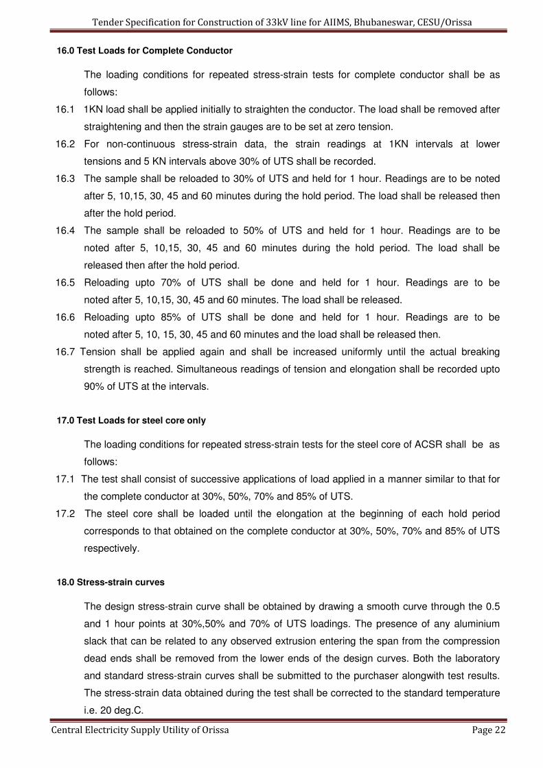
16.0 Test Loads for Complete Conductor
The loading conditions for repeated stress-strain tests for complete conductor shall be as
follows:
16.1 1KN load shall be applied initially to straighten the conductor. The load shall be removed after
straightening and then the strain gauges are to be set at zero tension.
16.2 For non-continuous stress-strain data, the strain readings at 1KN intervals at lower
tensions and 5 KN intervals above 30% of UTS shall be recorded.
16.3 The sample shall be reloaded to 30% of UTS and held for 1 hour. Readings are to be noted
after 5, 10,15, 30, 45 and 60 minutes during the hold period. The load shall be released then
after the hold period.
16.4 The sample shall be reloaded to 50% of UTS and held for 1 hour. Readings are to be
noted after 5, 10,15, 30, 45 and 60 minutes during the hold period. The load shall be
released then after the hold period.
16.5 Reloading upto 70% of UTS shall be done and held for 1 hour. Readings are to be
noted after 5, 10,15, 30, 45 and 60 minutes. The load shall be released.
16.6 Reloading upto 85% of UTS shall be done and held for 1 hour. Readings are to be
noted after 5, 10, 15, 30, 45 and 60 minutes and the load shall be released then.
16.7 Tension shall be applied again and shall be increased uniformly until the actual breaking
strength is reached. Simultaneous readings of tension and elongation shall be recorded upto
90% of UTS at the intervals.
17.0 Test Loads for steel core only
The loading conditions for repeated stress-strain tests for the steel core of ACSR shall be as
follows:
17.1 The test shall consist of successive applications of load applied in a manner similar to that for
the complete conductor at 30%, 50%, 70% and 85% of UTS.
17.2 The steel core shall be loaded until the elongation at the beginning of each hold period
corresponds to that obtained on the complete conductor at 30%, 50%, 70% and 85% of UTS
respectively.
18.0 Stress-strain curves
The design stress-strain curve shall be obtained by drawing a smooth curve through the 0.5
and 1 hour points at 30%,50% and 70% of UTS loadings. The presence of any aluminium
slack that can be related to any observed extrusion entering the span from the compression
dead ends shall be removed from the lower ends of the design curves. Both the laboratory
and standard stress-strain curves shall be submitted to the purchaser alongwith test results.
The stress-strain data obtained during the test shall be corrected to the standard temperature
i.e. 20 deg.C.

Tender Specification for Construction of 33kV line for AIIMS, Bhubaneswar, CESU/Orissa
Central Electricity Supply Utility of Orissa Page 23
19.0 DC RESISTANCE TEST ON COMPOSITE CONDUCTOR
On a conductor sample of minimum 5m length, two contact clamps shall be fixed with a pre-
determined bolt torque. The resistance of the sample shall be measured by a Kelvin double
bridge by placing the clamps initially zero metre and subsequently one metre apart. The test
shall be repeated at least five times and the average value recorded. The value obtained
shall be corrected to the value at 20 deg C as per clause no.12.8 of IS:398 (Part-II)-
1982/1996.The corrected resistance value at 20 deg.C shall conform to the requirements of
this specification.
20.0 Procedure Qualification test on welded Aluminium Strands.
Two Aluminium wires shall be welded as per the approved quality plan and shall be
subjected to tensile load. The breaking strength of the welded joint of the wire shall not be
less than the guaranteed breaking strength of individual strands.
21.0 Chemical Analysis of Aluminium and steel
Samples taken from the Aluminium and Steel ingots / coils/ strands shall be chemically/
Spectrographically analysed. The same shall be in conformity with the requirements stated in
this specification.
22.0 Chemical Analysis of zinc
Samples taken from the zinc ingots shall be chemically / spectrographically analyzed. The
same shall be in conformity with the requirements stated in this specification.
23.0 Visual and Dimensional check on Drums
The drums shall be visually and dimensionally checked to ensure that they conform to the
requirements of this specification.
24.0 REJECTION AND RETEST
24.1 In case of failure in any type test, the supplier is either required to manufacture fresh sample
lot and repeat all the tests successfully once or repeat that particular type test three times
successfully on the sample selected from the already manufactured lot at his own expenses.
In case a fresh lot is manufactured for testing then the lot already manufactured shall be
rejected.
24.2 If samples are taken for test after stranding and if any selected reel fails in the retest, the
manufacturer may test each and every reel and submit them for further inspection. All
rejected material shall be suitably marked and segregated.
5.0 CHECKING AND VERIFICATION OF LENGTH OF CONDUCTOR
The contractor should arrange for inspection by the representative of the purchaser specially
authorized for this purpose. At least 50% of the total number of drums of conductor subject to
minimum of two taken at random should be checked to ascertain the length of conductor.
Arrangements should be made available in the works of the manufacturer for transferring the
Tender Specification for Construction of 33kV line for AIIMS, Bhubaneswar, CESU/Orissa
Central Electricity Supply Utility of Orissa Page 24
conductor from one reel to another at the same time measuring the length of the conductor
so transferred by means of a meter.
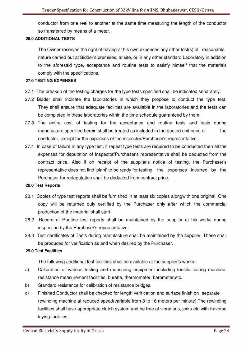
26.0 ADDITIONAL TESTS
The Owner reserves the right of having at his own expenses any other test(s) of reasonable
nature carried out at Bidder's premises, at site, or in any other standard Laboratory in addition
to the aforesaid type, acceptance and routine tests to satisfy himself that the materials
comply with the specifications.
27.0 TESTING EXPENSES
27.1 The breakup of the testing charges for the type tests specified shall be indicated separately.
27.2 Bidder shall indicate the laboratories in which they propose to conduct the type test.
They shall ensure that adequate facilities are available in the laboratories and the tests can
be completed in these laboratories within the time schedule guaranteed by them.
27.3 The entire cost of testing for the acceptance and routine tests and tests during
manufacture specified herein shall be treated as included in the quoted unit price of the
conductor, except for the expenses of the inspector/Purchaser's representative.
27.4 In case of failure in any type test, if repeat type tests are required to be conducted then all the
expenses for deputation of Inspector/Purchaser's representative shall be deducted from the
contract price. Also if on receipt of the supplier's notice of testing, the Purchaser's
representative does not find 'plant' to be ready for testing, the expenses incurred by the
Purchaser for redeputation shall be deducted from contract price.
28.0 Test Reports
28.1 Copies of type test reports shall be furnished in at least six copies alongwith one original. One
copy will be returned duly certified by the Purchaser only after which the commercial
production of the material shall start.
28.2 Record of Routine test reports shall be maintained by the supplier at his works during
inspection by the Purchaser's representative.
28.3 Test certificates of Tests during manufacture shall be maintained by the supplier. These shall
be produced for verification as and when desired by the Purchaser.
29.0 Test Facilities
The following additional test facilities shall be available at the supplier's works:
a) Calibration of various testing and measuring equipment including tensile testing machine,
resistance measurement facilities, burette, thermometer, barometer,etc.
b) Standard resistance for calibration of resistance bridges.
c) Finished Conductor shall be checked for length verification and surface finish on separate
rewinding machine at reduced speed(variable from 8 to 16 meters per minute).The rewinding
facilities shall have appropriate clutch system and be free of vibrations, jerks etc with traverse
laying facilities.
Tender Specification for Construction of 33kV line for AIIMS, Bhubaneswar, CESU/Orissa
Central Electricity Supply Utility of Orissa Page 25
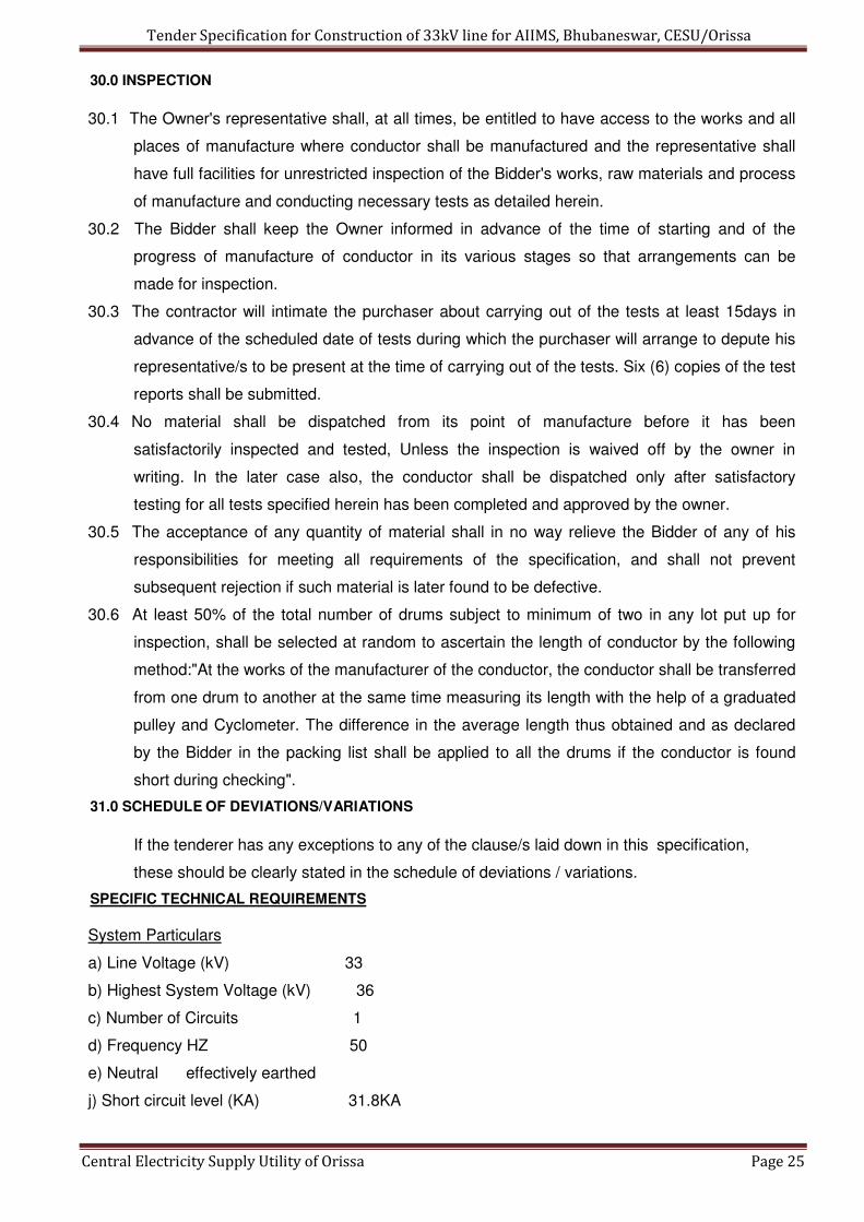
30.0 INSPECTION
30.1 The Owner's representative shall, at all times, be entitled to have access to the works and all
places of manufacture where conductor shall be manufactured and the representative shall
have full facilities for unrestricted inspection of the Bidder's works, raw materials and process
of manufacture and conducting necessary tests as detailed herein.
30.2 The Bidder shall keep the Owner informed in advance of the time of starting and of the
progress of manufacture of conductor in its various stages so that arrangements can be
made for inspection.
30.3 The contractor will intimate the purchaser about carrying out of the tests at least 15days in
advance of the scheduled date of tests during which the purchaser will arrange to depute his
representative/s to be present at the time of carrying out of the tests. Six (6) copies of the test
reports shall be submitted.
30.4 No material shall be dispatched from its point of manufacture before it has been
satisfactorily inspected and tested, Unless the inspection is waived off by the owner in
writing. In the later case also, the conductor shall be dispatched only after satisfactory
testing for all tests specified herein has been completed and approved by the owner.
30.5 The acceptance of any quantity of material shall in no way relieve the Bidder of any of his
responsibilities for meeting all requirements of the specification, and shall not prevent
subsequent rejection if such material is later found to be defective.
30.6 At least 50% of the total number of drums subject to minimum of two in any lot put up for
inspection, shall be selected at random to ascertain the length of conductor by the following
method:"At the works of the manufacturer of the conductor, the conductor shall be transferred
from one drum to another at the same time measuring its length with the help of a graduated
pulley and Cyclometer. The difference in the average length thus obtained and as declared
by the Bidder in the packing list shall be applied to all the drums if the conductor is found
short during checking".
31.0 SCHEDULE OF DEVIATIONS/VARIATIONS
If the tenderer has any exceptions to any of the clause/s laid down in this specification,
these should be clearly stated in the schedule of deviations / variations.
SPECIFIC TECHNICAL REQUIREMENTS
System Particulars
a) Line Voltage (kV) 33
b) Highest System Voltage (kV) 36
c) Number of Circuits 1
d) Frequency HZ 50
e) Neutral effectively earthed
j) Short circuit level (KA) 31.8KA

Tender Specification for Construction of 33kV line for AIIMS, Bhubaneswar, CESU/Orissa
Central Electricity Supply Utility of Orissa Page 26
TECHNICAL REQUIREMENTS
k) Conductor : Panther ACSR
l) IS applicable: IS-398 (part-II)1996 latest revision.
m) Wire diameter: Panther
Aluminium (mm) : 30/3.00
Steel(mm) : 7/3.00
n) Number of strands:
Steel centre
1st steel layer 6
1st Aluminium layer 12
2nd Aluminium layer 18
o) Sectional Area of :
Aluminium (sq. mm.)
212.1
p) Total Sectional :
261.5
q) Overall diameter (mm) : 21
r) Approximate weight : 974 (Kg./Km.)
s) Calculated D.C. resistance : 0.139 at 20 degrees C, maximum. (Ohms/km.)
t) Ultimate tensile strength : 89.67(KN)
u) Final modulas of elasticity: 80 (GN/sq.m)
v) Coefficient of Linear : 17.8 expansion x 10-6 per º C

Tender Specification for Construction of 33kV line for AIIMS, Bhubaneswar, CESU/Orissa
Central Electricity Supply Utility of Orissa Page 27
GURANTEED TECHNICAL PARTICULARS FOR
33kV, ACSR Panther Conductor
(To be submitted along with offer)
1. Maker's Name, Address & Country. :
2. a) Aluminium :
b) Steel wire :
c) Complete conductor :
CONDUCTOR :
3. Size & Code :
4. IS/International Standards applicable :
5. Wire diameter in mm
Aluminium : Steel :
6. Diameter of complete Conductor in mm :
7. Number of strands : Steel centre :
1st steel layer :
1st Aluminium layer :
2nd Aluminium layer :
8. Sectional Area of Aluminium in mm2 :
9. Total Sectional Area in mm2 :
10.Overall diameter in mm :
11.Weight in kg :
12. Calculated D.C. resistance at 20 degrees C, maximum. :
13. Continuous current rating at 75 degree C (Enclose supporting calculations) :
16. Ultimate tensile strength, kg/kN :
17. Final modulus of elasticity :
18. Co-efficient of Linear expansion. :
19. Lay-Ratio Maximum Minimum
Steel core 6 wire layer
Aluminium
1st layer
2nd layer
STRANDS
20. Technical particulars of Steel Aluminium
Aluminium and steel strands :
a) Diameter (mm) Standard : Maximum : Minimum :
b) Cross-sectional area of nominal diameter wire (sqmm) :
c) Weight in Kg./Km. :
d) Minimum breaking load in Kg/KN Before stranding :
After stranding :

Tender Specification for Construction of 33kV line for AIIMS, Bhubaneswar, CESU/Orissa
Central Electricity Supply Utility of Orissa Page 28
e) Minimum ultimate tensile stress of strand (KG/Sq mm) :
f) Co-efficient of linear expansion :
21. D.C. Resistance at 20 degrees C in ohms/Km :
22. Zinc coating of steel wire in gms/m2:
a) Number of 1 minute dips. :
b) Minimum weight of Zinc Coating:
c) Process of Galvanizing :
d) Quality of Zinc :
23. Joints in strands a) Steel :
b) Aluminium :
c) Method of making joint :
d) Ultimate tensile strength of joint :
24. Maximum single length of conductor which can be manufactured in km :
25. Standard length of each piece in Km. :
26. a) Tolerance if any on standard lengths :
b) Details of random lengths :
27. No. of standard length in one reel :
28. Type of Drums and IS applicable :
29. Dimensions of the Drum in cm. : (Drawing shall be enclosed)
30. Weight of the Drum in kg :
with conductor :
empty Drum with lagging :
31. Details of marking on conductor drum :
32. Whether the drums are suitable for use with tension stringing equipment. :
33. Standard according to which the conductor will be manufactured and tested :
a) Certification Mark if any :
b) Test certificate enclosed : Yes/No
34. Chemical composition of high carbon steel wire :
35. Initial & Final sag and Tension charts Furnished:
36. Stress/Strain data corresponding to different tensions, temperatures and time
furnished. :
37. Curves/tables of creep compensation corresponding to different tensions
temperatures furnished :
38. Other details if any :

Tender Specification for Construction of 33kV line for AIIMS, Bhubaneswar, CESU/Orissa
Central Electricity Supply Utility of Orissa Page 29
Section-III
R.S.Joist Pole
Tender Specification for Construction of 33kV line for AIIMS, Bhubaneswar, CESU/Orissa
Central Electricity Supply Utility of Orissa Page 30
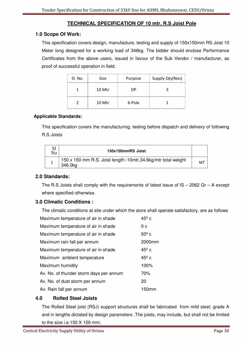
TECHNICAL SPECIFICATION OF 10 mtr, R.S Joist Pole
1.0 Scope Of Work:
This specification covers design, manufacture, testing and supply of 150x150mm RS Joist 10
Meter long designed for a working load of 346kg. The bidder should enclose Performance
Certificates from the above users, issued in favour of the Sub Vendor / manufacturer, as
proof of successful operation in field.
Sl. No. Size Purpose Supply Qty(Nos)
1 10 Mtr DP 3
2 10 Mtr 6-Pole 1
Applicable Standards:
This specification covers the manufacturing, testing before dispatch and delivery of following
R.S Joists
Sl No 150x150mmRS Joist
1 150 x 150 mm R.S. Joist length:-10mtr,34.6kg/mtr total weight 346.0kg
MT
2.0 Standards:
The R.S Joists shall comply with the requirements of latest issue of IS – 2062 Gr – A except
where specified otherwise.
3.0 Climatic Conditions :
The climatic conditions at site under which the store shall operate satisfactory, are as follows
Maximum temperature of air in shade 45º c
Maximum temperature of air in shade 0 c
Maximum temperature of air in shade 50º c
Maximum rain fall per annum 2000mm
Maximum temperature of air in shade 45º c
Maximum ambient temperature 45º c
Maximum humidity 100%
Av. No. of thunder storm days per annum 70%
Av. No. of dust storm per annum 20
Av. Rain fall per annum 150mm
4.0 Rolled Steel Joists
The Rolled Steel joist (RSJ) support structures shall be fabricated from mild steel, grade A
and in lengths dictated by design parameters .The joists, may include, but shall not be limited
to the size i.e.150 X 150 mm;

Tender Specification for Construction of 33kV line for AIIMS, Bhubaneswar, CESU/Orissa
Central Electricity Supply Utility of Orissa Page 31
4.1 Dimensions and Properties
RSJ DESIGNATION 150 x 150 mm
ISHB Length of Joist in Mtr with +100mm/-
0% Tolerance
10mtr
Weight kg/m with±2.5% Tolerance 30.6
Sectional Area (cm2) 39.00
Depth(D) of Section (mm) with
+3.0mm/ -2.0mm Tolerance as per IS
1852-1985
150.00
Width (B)of Flange (mm) with
±2.5mm Tolerance for116 x 100 mm
ISMB & ±4.0mm Tolerance for 150 x
150 mm ISHB IS 1852-1985
150.00
Thickness of Flange (Tf) (mm)
with±1.5mm Tolerance
9.00
Thickness of Web(Tw) (mm)
with±1.0mm Tolerance
8.40
Corner Radius of fillet or root (R1) (mm) 8.00
Corner Radius of Tow (R2) (mm) 4.00
Moment of Inertia
Ixx (cm4) Iyy (cm4)
1540.00
460.00 Radius of Gyration (cm) Rxx
Ryy
6.29
3.44
Flange Slope(α) in Degree 94.0
Tolerance in Dimension As perIS:1852
4.2 MECHANICAL PROPERTIES:
Tensile Test : Requirement as per IS:2062/
1999 Grade-A Yeild Stress(MPa) Min250 Tensile Strength(MPa) Min410 Lo=(5.65√So)Elongation% Min23 Bend Test Shall not Crack
4.3. CHEMICAL PROPERTIES:
Chemical Composition Requirement as per IS:2062/
1999 Grade-A Permissible variation over the Specified Limit,Percent,Max
Grade A - Chemical Name Fe-410W A - Carbon(%Max.) 0.23 0.02

Tender Specification for Construction of 33kV line for AIIMS, Bhubaneswar, CESU/Orissa
Central Electricity Supply Utility of Orissa Page 32
Manganese(%Max.) 1.5 0.05 Sulphur(%Max.) 0.050 0.005 Phosphorous(%Max.) 0.050 0.005 Silicon(%Max.) 0.40 0.03 Carbon Equivalent(%Max.) 0.42 - Deoxidation Mode Semi-killed or killed - Supply condition As rolled - 4.4. However, In case of any discrepancy between the above data & the relevant ISS, the values indicated in the IS shall prevail.
4.5. The Acceptance Tests shall be carried out as per Relevant ISS.
5.2.150x150mm RS Joists:
RS Joists of Specific Weight 30.6kg/mtr with length of each type of pole being 10mtr pole
weighing 346.0Kg for specified number of poles with specified weight in MT as given in
the NIT table given above shall have to be supplied as per IS:2062;2006 Grade”A” ,
IS:808;1989/2001, IS1608:1995 & IS:12779-1989 and their latest amendment if any
complying the required Dimension, Weight, Chemical & Mechanical properties confirming to
the relevant IS, as per the Tolerance given Below.
5.3. APPLICABLE TOLLERANCES :
2. Length of each pole = + 100mm / - 0 % As per relevant IS: 12779-1989
(With proportionate change in no of Poles)
3. Specific Weight of RS Joists = ±2.5% As per relevant IS: 1852/1985
3. Weight for whole lot of supply for all categories = ±3.0% As per relevant IS: 12779-1989 for
both type of RS Joists.
6.0. EMBOSSING ON EACH R.S JOIST:
Following distinct non-erasable embossing is to be made on each R.S Joists .
a) Name & Logo of the
Manufacturer. b) B.I.S Logo (ISI
Mark) if applicable. c) Size of the
R.S Joist
Tender Specification for Construction of 33kV line for AIIMS, Bhubaneswar, CESU/Orissa
Central Electricity Supply Utility of Orissa Page 33
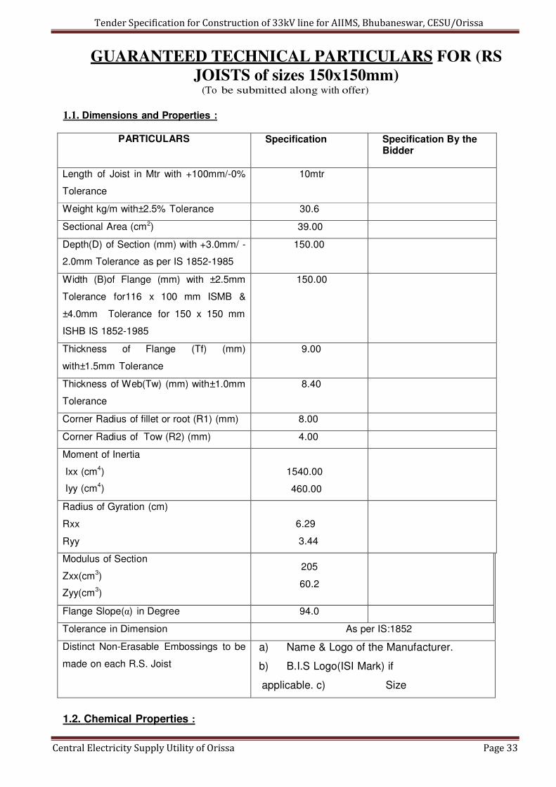
GUARANTEED TECHNICAL PARTICULARS FOR (RS
JOISTS of sizes 150x150mm) (To be submitted along with offer)
1.1. Dimensions and Properties :
PARTICULARS Specification Specification By the
Bidder
Length of Joist in Mtr with +100mm/-0%
Tolerance
10mtr
Weight kg/m with±2.5% Tolerance 30.6
Sectional Area (cm2) 39.00
Depth(D) of Section (mm) with +3.0mm/ -
2.0mm Tolerance as per IS 1852-1985
150.00
Width (B)of Flange (mm) with ±2.5mm
Tolerance for116 x 100 mm ISMB &
±4.0mm Tolerance for 150 x 150 mm
ISHB IS 1852-1985
150.00
Thickness of Flange (Tf) (mm)
with±1.5mm Tolerance
9.00
Thickness of Web(Tw) (mm) with±1.0mm
Tolerance
8.40
Corner Radius of fillet or root (R1) (mm) 8.00
Corner Radius of Tow (R2) (mm) 4.00
Moment of Inertia
Ixx (cm4)
Iyy (cm4)
1540.00
460.00
Radius of Gyration (cm)
Rxx
Ryy
6.29
3.44
Modulus of Section
Zxx(cm3)
Zyy(cm3)
205
60.2
Flange Slope(α) in Degree 94.0
Tolerance in Dimension As per IS:1852
Distinct Non-Erasable Embossings to be
made on each R.S. Joist
a) Name & Logo of the Manufacturer.
b) B.I.S Logo(ISI Mark) if
applicable. c) Size
1.2. Chemical Properties :

Tender Specification for Construction of 33kV line for AIIMS, Bhubaneswar, CESU/Orissa
Central Electricity Supply Utility of Orissa Page 34
Tensile Test : Requirement as
per IS:2062/ 1999 Grade-A
Manufacturer’s Data
Yeild Stress(MPa) Min250 Tensile Strength(MPa) Min410 Lo=(5.65√So)Elongation% Min23 Bend Test Shall not Crack
1.3.Mechanical Properties :
Chemical Composition Requirement as per IS:2062/ 1999 Grade-
Permissible variation over the Specified Limit,Percent,Max
Manufacturer’s Data
Grade A -
Chemical Name Fe-410W A -
Carbon(%Max.) 0.23 0.02
Manganese(%Max.) 1.5 0.05
Sulphur(%Max.) 0.050 0.005
Phosphorous(%Max.) 0.050 0.005
Silicon(%Max.) 0.40 0.03
Carbon Equivalent(%Max.) 0.42 -
Deoxidation Mode Semi-killed or
-
Supply condition As rolled -
However, In case of any discrepancy between the above data & the relevant ISS, the values indicated in the IS shall prevail.
The Acceptance Tests shall be Carried out as per Relevant ISS. The RS Joists shall be manufactured confirming to the relevant IS with Manufacturer’s name/logo & B.I.S Logo if applicable embossed on it.
Tender Specification for Construction of 33kV line for AIIMS, Bhubaneswar, CESU/Orissa
Central Electricity Supply Utility of Orissa Page 35
Section-IV
Insulators & Hardware fittings
Tender Specification for Construction of 33kV line for AIIMS, Bhubaneswar, CESU/Orissa
Central Electricity Supply Utility of Orissa Page 36
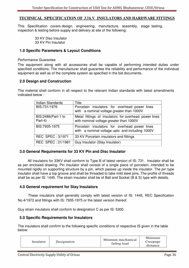
TECHNICAL SPECIFICATION OF 3 3 k V INSULATORS AND HARDWARE FITTINGS
This Specification covers design, engineering, manufacture, assembly, stage testing, inspection & testing before supply and delivery at site of the following:
33 KV Disc Insulator 33 KV Pin Insulator
1.0 Specific Parameters & Layout Conditions
Performance Guarantee
The equipment along with all accessories shall be capable of performing intended duties under specified conditions. The manufacturer shall guarantee the reliability and performance of the individual equipment as well as of the complete system as specified in the bid documents.
2.0 Design and Construction
The material shall conform in all respect to the relevant Indian standards with latest amendments indicated below :
Indian Standards Title BIS:731/1976 Porcelain insulators for overhead power lines
with a nominal voltage greater than 1000V
BIS:2486(Part-1 to Part-4)
Metal fittings of insulators for overhead power lines with nominal voltage greater than 1000V
BIS:7935-1975 Porcelain insulators for overhead power lines with a nominal voltage upto and including 1000V
REC SPEC : 3/1971 33 KV Porcelain insulators and fittings
REC SPEC : 21/1981 Guy Insulator (Stay Insulator)
3.0 General Requirements for 33 KV Pin and Disc Insulator
All insulators for 33KV shall conform to Type B of latest version of IS: 731. Insulator shall be as per enclosed drawing. Pin insulator shall consist of a single piece of porcelain, intended to be mounted rigidly on supporting structure by a pin, which passes up inside the insulator. The pin type insulator shall have a top groove and shall be threaded to take mild steel pins. The profile of threads shall be as per IS: 1445. The strain insulator shall be of Ball and Socket (B & S) type with details.
4.0 General requirement for Stay Insulators
These insulators shall generally comply with latest version of IS: 1445, REC Specification
No.4/1972 and fittings with IS: 7935-1975 or the latest version thereof.
Guy strain insulators shall conform to designation C as per IS: 5300.
5.0 Specific Requirements for Insulators The insulators shall confirm to the following specific conditions of respective IS given in the table below:
Insulator
Designation
Minimum mechanical
failing load
Minimum
Creepage
distance

Tender Specification for Construction of 33kV line for AIIMS, Bhubaneswar, CESU/Orissa
Central Electricity Supply Utility of Orissa Page 37
Pin 10 KN 320 mm Pin 10 KN 580 mm Disc
Type –B of IS 731
Type –B of IS 731 70 KN (for B & S type) 320 mm
33 KV
Stay Type – C of IS
1445
88 KN
57 mm
6.0 Insulator Materials
6.1 Porcelain: The porcelain used in the manufacture of shells shall be sound, free from defects
thoroughly vitrified and smoothly glazed. It should not engage directly with hard metal.
6.2 Glaze: The finished porcelain shall be glazed in brown color. The glaze shall cover all exposed parts
of the insulator and shall have a good lustre, smooth surface and good performance under
the extreme weather conditions of a tropical climate. It shall not crack or chip by ageing under
the normal service conditions. The glaze shall have the same co-efficient of expansion as if
the porcelain body throughout the working temperature range. The insulator shall be so
designed that the stresses due to expansion and contraction in any part of the insulator shall
not lead to deterioration.
6.3 Cement:
Cement used in the manufacture of the insulator shall not cause fracture by expansion or
loosening by contraction. The cement shall not give rise to chemical reaction with metal
fittings and its thickness shall be as small and uniform as possible. Proper care shall be taken
to correctly centre and locate individual parts during cementing.
7.0 QUALITY ASSURANCE AND TESTING
7.1 Type Tests:
Reports of the following type tests conducted in any NABL accredited laboratory, shall
have to be submitted along with the bid.
a. Visual examination
b. Verification of dimensions c. Visible Discharge test (dry)
d. Impulse voltage withstand and flashover test(dry)
e. Power frequency voltage withstands and flashover test
(i) dry (ii) wet.
f. Temperature Cycle test
g. Mechanical failing Load Test (for pin insulator only) to be carried out
as per procedure described at Sub-clause12.2.5 below
h. 24 hour Mechanical Strength Test for Strain Insulator
i. Puncture Test
j. Porosity Test
k. Galvanizing Test
l. Electro-mechanical failing test (for Strain Insulator only) to be carried
out.
m. Thermal mechanical performance test (for Strain insulators only) to be
carried out.
Note: Type test reports shall be submitted for acceptance which should not be more than five (05) years old as on date of bid opening.
Tender Specification for Construction of 33kV line for AIIMS, Bhubaneswar, CESU/Orissa
Central Electricity Supply Utility of Orissa Page 38
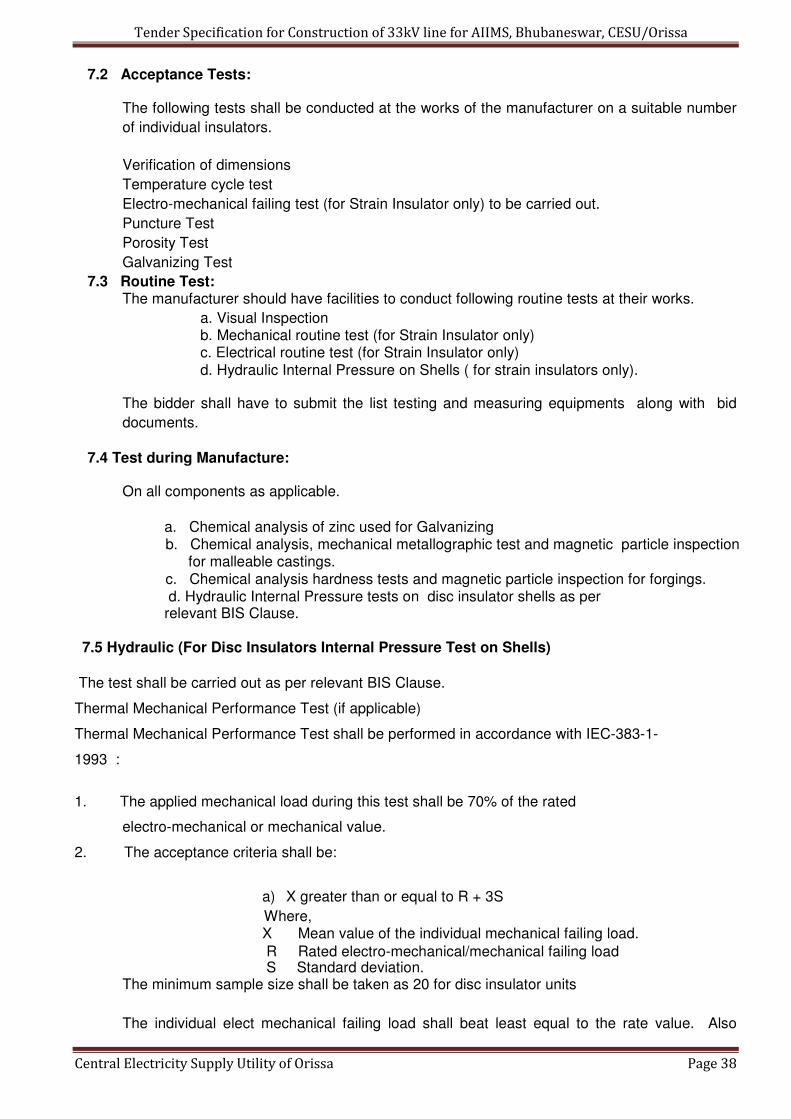
7.2 Acceptance Tests:
The following tests shall be conducted at the works of the manufacturer on a suitable number
of individual insulators.
Verification of dimensions
Temperature cycle test
Electro-mechanical failing test (for Strain Insulator only) to be carried out.
Puncture Test
Porosity Test
Galvanizing Test
7.3 Routine Test: The manufacturer should have facilities to conduct following routine tests at their works.
a. Visual Inspection b. Mechanical routine test (for Strain Insulator only) c. Electrical routine test (for Strain Insulator only) d. Hydraulic Internal Pressure on Shells ( for strain insulators only).
The bidder shall have to submit the list testing and measuring equipments along with bid
documents.
7.4 Test during Manufacture:
On all components as applicable.
a. Chemical analysis of zinc used for Galvanizing b. Chemical analysis, mechanical metallographic test and magnetic particle inspection
for malleable castings. c. Chemical analysis hardness tests and magnetic particle inspection for forgings. d. Hydraulic Internal Pressure tests on disc insulator shells as per relevant BIS Clause.
7.5 Hydraulic (For Disc Insulators Internal Pressure Test on Shells)
The test shall be carried out as per relevant BIS Clause.
Thermal Mechanical Performance Test (if applicable)
Thermal Mechanical Performance Test shall be performed in accordance with IEC-383-1-
1993 :
1. The applied mechanical load during this test shall be 70% of the rated
electro-mechanical or mechanical value.
2. The acceptance criteria shall be:
a) X greater than or equal to R + 3S
Where, X Mean value of the individual mechanical failing load.
R Rated electro-mechanical/mechanical failing load S Standard deviation.
The minimum sample size shall be taken as 20 for disc insulator units
The individual elect mechanical failing load shall beat least equal to the rate value. Also
Tender Specification for Construction of 33kV line for AIIMS, Bhubaneswar, CESU/Orissa
Central Electricity Supply Utility of Orissa Page 39
puncture shall not occur before the ultimate fracture.
7.6 Electromechanical/Mechanical Failing Load Test.
This test shall be performed in accordance of IEC 383 with the following acceptance.
X greater than or equal to R + 3S
Where,
X Mean value of the electro-mechanical/mechanical/failing load
R Rated electro-mechanical/mechanical failing load
S Standard deviation.
The minimum sample size shall be taken as 20 for disc insulators units. However, for larger
lot size, IEC 591 shall be applicable.
The individual electro-mechanical/mechanical failing load shall be at least equal to the rated
value. Also electrical puncture shall not occur before the ultimate fracture.
Note: The purchaser had right to waive any type/special test if the supplier produces the test
report for such tests conducted on identical Insulators.
8.0 Packing and Marking
Each insulator shall be visibly and indelibly marked as following:
Name and Trademark of manufacturer
Month / Year of manufacturer
Minimum failing load in KN
Marking on porcelain shall be printed / engraved and shall be applied before firing.
All insulators shall be packed in strong seasoned wooden crates. The gross weight of the
crates along with the material shall not normally exceed 200 Kg to avoid handling problem.
The packing shall be of sufficient strength to withstand rough handling during transit, storage
at site and subsequent handling in the field.
Suitable cushioning, protective padding or spacers shall be provided to prevent damage or
deformation during transit and handling.
All packing cases shall be marked legibly and correctly so as to ensure safe arrival at their
destination and to avoid the possibility of goods being lost or wrongly dispatched on
account of faulty packing and faulty or illegible markings. Each wooden case/crate shall have
all the markings stenciled on it in indelible ink.
Tender Specification for Construction of 33kV line for AIIMS, Bhubaneswar, CESU/Orissa
Central Electricity Supply Utility of Orissa Page 40
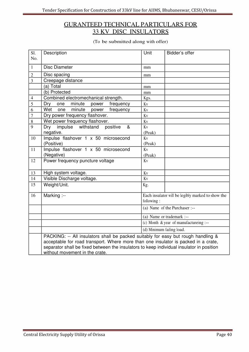
GURANTEED TECHNICAL PARTICULARS FOR
33 KV DISC INSULATORS
(To be submitted along with offer)
Sl.
No. Description Unit Bidder’s offer
1 Disc Diameter mm
2 Disc spacing mm
3 Creepage distance
(a) Total mm
(b) Protected mm 4 Combined electromechanical strength. Kgs.
5 Dry one minute power frequency Kv
6 Wet one minute power frequency Kv
7 Dry power frequency flashover. Kv
8 Wet power frequency flashover. Kv 9 Dry impulse withstand positive &
negative. Kv
(Peak)
10 Impulse flashover 1 x 50 microsecond (Positive)
Kv
(Peak)
11 Impulse flashover 1 x 50 microsecond (Negative)
Kv
(Peak)
12 Power frequency puncture voltage Kv
13 High system voltage. Kv 14 Visible Discharge voltage. Kv
15 Weight/Unit. Kg.
16 Marking :-- Each insulator will be legibly marked to show the
following :
(a) Name of the Purchaser :--
(a) Name or trademark :--
(c) Month & year of manufactureing :--
(d) Minimum failing load.
PACKING: -- All insulators shall be packed suitably for easy but rough handling & acceptable for road transport. Where more than one insulator is packed in a crate, separator shall be fixed between the insulators to keep individual insulator in position without movement in the crate.

Tender Specification for Construction of 33kV line for AIIMS, Bhubaneswar, CESU/Orissa
Central Electricity Supply Utility of Orissa Page 41
GURANTEED TECHNICAL PARTICULARS FOR
33 KV PIN INSULATORS
(To be submitted along with offer)
Sl.
No. Description Bidders offer
1 Normal working voltage
2 High system voltage.
3 Visible Discharge voltage dry PF.
4 1 Minute withstand voltage wet PF.
5 1 Minute withstand voltage.................
6 PF puncture withstand voltage.
7 Impulse withstand voltage :
8 Impulse flashover voltage :
9 Minimum failing load.
10 Minimum creepage distance.
11 Colour of glaze.
12 Weight per unit.
13 Size of insulator. (Height)
14 Material of thimble.
15 Steel head.
16 Standard.
17 Tolerance.
18 Marking :-- Each insulator will be legibly marked to
show the following :
(a) Name of the Purchaser :--
(a) Name or trademark :--
(c) Month & year of manufactureing :--
(d) Minimum failing load.
PACKING: -- All insulators shall be packed in wooden crates suitable for easy but
rough handling & acceptable for road transport. Where more than one insulator are
packed in a crate, separator shall be fixed between the insulators to keep individual
insulator in position

Tender Specification for Construction of 33kV line for AIIMS, Bhubaneswar, CESU/Orissa
Central Electricity Supply Utility of Orissa Page 42
DRAWINGS:

Tender Specification for Construction of 33kV line for AIIMS, Bhubaneswar, CESU/Orissa
Central Electricity Supply Utility of Orissa Page 43
Tender Specification for Construction of 33kV line for AIIMS, Bhubaneswar, CESU/Orissa
Central Electricity Supply Utility of Orissa Page 44
9.0 TECHNICAL SPECIFICATIONS OF HARDWARE FITTING FOR 33kV DISC
INSULATOR & 33 kV GI PIN INSULATOR
9.1 SCOPE : This Specification covers design, engineering, manufacture, assembly, stage testing,
inspection & testing before supply and delivery at site
Hardware fittings for 33 KV Disc Insulators and 33 KV GI Pins.
9.2 APPLICABLE STANDARD :
I. Fittings for Disc insulators shall comply with the requirements of IS : 2486 and REC specification No. 3/1971, 4/1972. II. 33 kV GI shall comply with the requirements of IS : 2486.
9.3 GENERAL REQUIREMENTS:
I. Fittings for Disc Insulators :
Cross arm strap confirming to IS 2486 (Part II)
Forged Steel ball eye for attaching the socket end of the Disc insulator to the
cross arm strap. Forging shall be made of steel as per IS: 2004 Grade 4.
Aluminum alloy thimble socket made out of permanent high strength aluminum alloy
for attaching the disc insulator at one end and for accommodating the loop of
conductor (Panther ACSR) at the other end. The thimble socket shall be attached to
the disc insulator with the help of locking pin as per the dimensions given in IS: 2486
(Part II).
The tension hardware with four bolts strain hardware shall have minimum slip
strength not less than 95% of the strength of respective conductor.
Failing load shall be minimum 70 KN.
II. 33 kV GI Pin :
The pins shall be of single piece obtained by the process of forging. They will not be
made by any process using more than one piece of material. The pin will have good
finish, free from flaws and other defects. The finish of the collar shall be such that a
sharp angle between the collar and the shank is avoided. All ferrous pins, nuts and
washers, except those made of stainless steel shall be galvanized by hot dip process.
Other fittings, i.e. flat washers and spring washers may be electro-galvanized as per
IS: 2486. The threads of nuts, and toped holes, when cut after galvanization shall be
well oiled or greased.
The pins shall be as per relevant figure indicated in IS 2486 (part II) having stalk
length of 165 mm and shank length of 150 mm with minimum failing load of 10
KN with small heads and shall match with the pin type insulators with cemented
zinc thimble having similar threads.
9.4 TESTS:
The hardware fittings and pins shall be tested as per IS: 2486 (part-1):1993 I. Type Test:
The bidder has to enclose the reports of the following type tests carried out in any govt. recognized laboratory along with the bid documents.
a) Checking of Threads on Heads

Tender Specification for Construction of 33kV line for AIIMS, Bhubaneswar, CESU/Orissa
Central Electricity Supply Utility of Orissa Page 45
b) Galvanizing Test
c) Visual Examination
d) Mechanical Test.
II. Acceptance Tests:
Following tests shall be carried out at the works of the manufacturer before dispatch. a) Checking of Threads on Heads
b) Galvanizing Test
c) Visual Examination
d) Mechanical Test.
10.0 TECHNICAL SPECIFICATIONS OF NUTS & BOLTS
10.1 SCOPE: This specification covers manufacture, testing and supply of ISI Marked bolts and nuts made
of black mild steel. All bolts and nuts shall have hexagonal heads, the heads being forged out
of solid truly concentric, and square with the shank, which must be perfectly straight. The half
thread GI nuts and bolts with 1 plane washer and 1 spring 1 washer completes 1 set. The
assorted sizes are as following :
Sl. No. Size Appx. Quantity (In Kg)
1 M 16 x 40 mm (Full Thread) As per actual
2 M 16 x 65 mm -do-
3 M 16 x 125 mm -do-
4 M 16 x 150 mm -do-
5 M 16 x 225 mm -do-
6 M 16 x 250 mm -do-
7 M 16 x 300 mm -do-
8 M 16 x 325 mm -do-
9 M 10 x 50 mm -do-
10.2 APPLICABLE STANDARDS
The Bolts & Nuts shall conform to IS: 6639 and galvanized as per IS: 1367 (Part-13)/ IS-2629.
10.3 GENERAL REQUIREMENTS
a) Bolts up to M16 and having length up to 10 times the diameter of the bolt should
be manufactured by cold forging and thread rolling process to obtain good and
reliable mechanical properties and effective dimensional control. The shear
strength of bolt for 5.6 grade should be 310 MPA minimum as per IS-2427. Bolts
should be provided with washer face in accordance with IS: 1363 Part-I to ensure
proper bearing.
b) Nuts should be double chamfered as per the requirement of IS: 1363 Part-III-
1984. The manufacturer should ensure that nuts should not be over tapped
beyond 0.4 mm oversize on effective diameter for size up to M16
c) Fully threaded bolts shall not be used. The length of the bolt shall be such that the
threaded portion shall not extend into the place of contact of the component parts.
All bolts shall be threaded to take the full depth of the nuts and threaded enough to
Tender Specification for Construction of 33kV line for AIIMS, Bhubaneswar, CESU/Orissa
Central Electricity Supply Utility of Orissa Page 46
permit the firm gripping of the component parts but no further. It shall be ensured
that the threaded portion of the bolt protruded not less than 3 mm and not more
than 8 mm when fully tightened. All nuts shall fit and tight to the point where shank
of the bolt connects to the head.
d) Flat washers and spring washers shall be provided wherever necessary and shall
be of positive lock type. Spring washers shall be electro-galvanized. The
thickness of washers shall conform to IS: 2016. The bidder shall furnish bolt
schedules giving thickness of components connected the nut and the washer and
the length of shank and the threaded portion of bolts and size of holes and any
other special details of this nature.
e) To obviate bending stress in bolt, it shall not connect aggregate thickness more
than three time its diameter. Bolts at the joints shall be so staggered that nuts may
be tightened with spanners without fouling.
f) To ensure effective in-process quality control it is essential that the
manufacturer should have all the testing facilities for tests like weight of zinc
coating, shear strength, other testing facilities etc, in-house. The agency should
also have proper Quality Assurance system which shall be in line with the
requirement of this specification and IS: 14000 services Quality System standard.
Fasteners of grade higher than 8.8 shall not to be used.
10.4 Raw Materials
MS round 16mm/12mm used shall be tested for quality as per IS: 2062 Gr.”A”.
The dimensions of the bolts & nuts and tolerances shall conform to IS: 1363 with their
latest amendments in all respect. The eccentricity and angular errors of various elements
shall be within specified limits as per IS: 1367/1967 with its latest amendments. The bolts &
nuts shall be free from forging and threading defects such as cuts, splits, burns,
bulging, taper, eccentricity, loose fill etc., which may affect their serviceability.
The bolt heads and nuts shall be chamfered on one face only and other face shall
be machined made. Mechanical property requirement of tester shall conform to IS:
1367 (Part- III)-1979 property class 4.6 for bolts and property class-5 for nuts as per IS:
1367 (Part-VI)-1980. The bolts and nuts shall be supplied in well- cleaned conditions and
suitably protected against corrosion in individual bags of 50kgs.
10.5 GALVANISING
It is required for galvanizing the Stay Clamps as following:
a) All galvanizing shall be carried out by the hot dip process, in accordance
with Specification IS 2629. However, high tensile steel nuts, bolts and spring washer
shall be electro galvanized to Service Condition 4. The zinc coating shall be
smooth, continuous and uniform. It shall be free from acid spot and shall not scale,
blister or be removable by handling or packing. There shall be no impurities in the
zinc or additives to the galvanic bath which could have a detrimental effect on the
durability of the zinc coating.
b) Before picking, all welding, drilling, cutting, grinding and other finishing
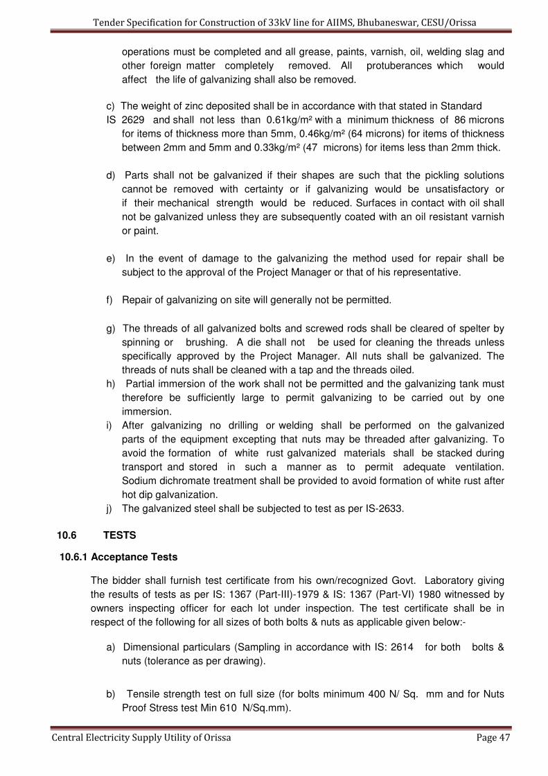
Tender Specification for Construction of 33kV line for AIIMS, Bhubaneswar, CESU/Orissa
Central Electricity Supply Utility of Orissa Page 47
operations must be completed and all grease, paints, varnish, oil, welding slag and
other foreign matter completely removed. All protuberances which would
affect the life of galvanizing shall also be removed.
c) The weight of zinc deposited shall be in accordance with that stated in Standard
IS 2629 and shall not less than 0.61kg/m² with a minimum thickness of 86 microns
for items of thickness more than 5mm, 0.46kg/m² (64 microns) for items of thickness
between 2mm and 5mm and 0.33kg/m² (47 microns) for items less than 2mm thick.
d) Parts shall not be galvanized if their shapes are such that the pickling solutions
cannot be removed with certainty or if galvanizing would be unsatisfactory or
if their mechanical strength would be reduced. Surfaces in contact with oil shall
not be galvanized unless they are subsequently coated with an oil resistant varnish
or paint.
e) In the event of damage to the galvanizing the method used for repair shall be
subject to the approval of the Project Manager or that of his representative.
f) Repair of galvanizing on site will generally not be permitted.
g) The threads of all galvanized bolts and screwed rods shall be cleared of spelter by
spinning or brushing. A die shall not be used for cleaning the threads unless
specifically approved by the Project Manager. All nuts shall be galvanized. The
threads of nuts shall be cleaned with a tap and the threads oiled.
h) Partial immersion of the work shall not be permitted and the galvanizing tank must
therefore be sufficiently large to permit galvanizing to be carried out by one
immersion.
i) After galvanizing no drilling or welding shall be performed on the galvanized
parts of the equipment excepting that nuts may be threaded after galvanizing. To
avoid the formation of white rust galvanized materials shall be stacked during
transport and stored in such a manner as to permit adequate ventilation.
Sodium dichromate treatment shall be provided to avoid formation of white rust after
hot dip galvanization.
j) The galvanized steel shall be subjected to test as per IS-2633.
10.6 TESTS
10.6.1 Acceptance Tests
The bidder shall furnish test certificate from his own/recognized Govt. Laboratory giving
the results of tests as per IS: 1367 (Part-III)-1979 & IS: 1367 (Part-VI) 1980 witnessed by
owners inspecting officer for each lot under inspection. The test certificate shall be in
respect of the following for all sizes of both bolts & nuts as applicable given below:-
a) Dimensional particulars (Sampling in accordance with IS: 2614 for both bolts &
nuts (tolerance as per drawing).
b) Tensile strength test on full size (for bolts minimum 400 N/ Sq. mm and for Nuts
Proof Stress test Min 610 N/Sq.mm).

Tender Specification for Construction of 33kV line for AIIMS, Bhubaneswar, CESU/Orissa
Central Electricity Supply Utility of Orissa Page 48
c) Power load test on full size bolts and M-12-51400 N for 15 Sec. d) Head
soundness tests for bolts (no fracture). e) Brinell hardness tests or Rockwell
Hardness or Vickers’s Hardness tests for bolts min. 114 and max. 209 or min.67 &
max. 95 or min.120 & max.220 respectively. For nuts Vicker’s Hardness min. 130 &
max. 302.
10.6.2 PRE-DESPATCH INSEPCTION
The bidder shall arrange to carryout acceptance tests in presence of owner’s inspecting
officer in his own laboratory. In case testing facilities are not available at his works he will
make necessary arrangements for carrying out these tests at a Govt. Recognized lab at
his own expenses(s) and will provide all testing arrangement for Owner’s representative to
witness the tests.
10.6.3 MARKINGS
On the bolt head, there shall be identification marking of the manufacturer as well as
property class “4.6”. If possible property calls “5” shall be marked on Nuts also. Further
“ISI” mark shall be marked on Sunny Bags for proper identifications.
GURANTEED TECHNICAL PARTICULARS FOR
NUTS & BOLTS (To be submitted along with offer)
Sl. No. Particulars Bidder’s Offer
1 Length of Bolt (in MM)
2 Dia of Bolt (In MM)
3 Pitch of Thread (In MM)
4 Full Thread or Half Thread
5 Dimension of Head
6 Size & Thickness of Plain Washer
7 Size & Thickness of Spring Washer
8 Thickness of GI Coating
9 Weight of one complete set

Tender Specification for Construction of 33kV line for AIIMS, Bhubaneswar, CESU/Orissa
Central Electricity Supply Utility of Orissa Page 49
11.0 TECHNICAL SPECIFICATIONS OF DANGER BOARD
11.1 SCOPE:
This Specification covers manufacture, testing and supply to the owner’s stores of Danger
Notice Plates to be displayed in accordance with Rule no.35 of Indian Electricity Rules,
1956.
11.2 APPLICABLE STANDARDS
The danger Notice Plates shall comply with IS: 2551-1982 and REC Spec. No. 57/1993 or
the latest version thereof.
11.3 DIMENSIONS
The size of Danger Notice shall be as following :
For display at 33 KV installations – 250 x 200mm
The corner of the plate shall be rounded off.
The locations of fixing holes as shown in Fig. 1 to 4 is provisional and can be modified to
suit the requirement of the purchaser.
11.4 LETTERINGS
All letterings shall certainly spaced. The dimension of the letters, figures and their
respective position shall be as per standard. The size of letters in the words in each
languages and spacing earmarked for them.
11.5 LANGUAGES
Under Rule No.35 of Indian Electricity Rules, 1956, the owner of every medium high
and extra high voltage installation is required to affix permanently in a conspicuous
position a danger notice in Hindi or English and , in addition, in the local languages, with
the sign of skull and bones.
The type and sizes of lettering to be done in Odia is indicated in the specimen danger
notice plates.
Adequate space has been provided in the specimen danger notice for having the letterings
in local languages for the equivalent of ‘Danger’: “33000” and “volts”.
11.6 MATERIAL AND FINISH
The plates shall be made from mild steel sheet of at least 1.6 mm thick and vitreous
enameled white, with letters, figures and conventional skull and cross bones in signal red
color (refers IS:5-1978) on the front side. The rear side of the plate shall also be enameled.
11.7 TESTS
The following tests shall be carried out: Visual examination as per IS: 2551-1982.
Dimensional check as per IS:2551-1982.
Test for weather proofness as per IS:8709-1977 (or its latest version)
11.8 MARKING
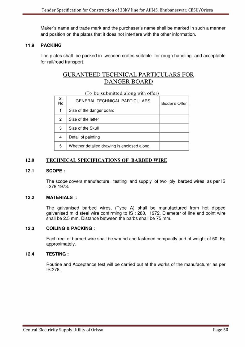
Tender Specification for Construction of 33kV line for AIIMS, Bhubaneswar, CESU/Orissa
Central Electricity Supply Utility of Orissa Page 50
Maker’s name and trade mark and the purchaser’s name shall be marked in such a manner
and position on the plates that it does not interfere with the other information.
11.9 PACKING
The plates shall be packed in wooden crates suitable for rough handling and acceptable
for rail/road transport.
GURANTEED TECHNICAL PARTICULARS FOR
DANGER BOARD
(To be submitted along with offer) Sl. No
GENERAL TECHNICAL PARTICULARS
Bidder’s Offer
1 Size of the danger board
2 Size of the letter
3 Size of the Skull
4 Detail of painting
5 Whether detailed drawing is enclosed along
12.0 TECHNICAL SPECIFICATIONS OF BARBED WIRE 12.1 SCOPE :
The scope covers manufacture, testing and supply of two ply barbed wires as per IS : 278,1978.
12.2 MATERIALS :
The galvanised barbed wires, (Type A) shall be manufactured from hot dipped galvanised mild steel wire confirming to IS : 280, 1972. Diameter of line and point wire shall be 2.5 mm. Distance between the barbs shall be 75 mm.
12.3 COILING & PACKING :
Each reel of barbed wire shall be wound and fastened compactly and of weight of 50 Kg approximately.
12.4 TESTING :
Routine and Acceptance test will be carried out at the works of the manufacturer as per IS:278.
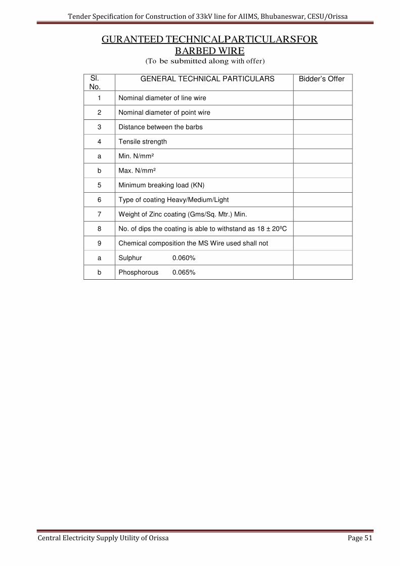
Tender Specification for Construction of 33kV line for AIIMS, Bhubaneswar, CESU/Orissa
Central Electricity Supply Utility of Orissa Page 51
GURANTEED TECHNICAL PARTICULARS FOR
BARBED WIRE (To be submitted along with offer)
Sl. No.
GENERAL TECHNICAL PARTICULARS Bidder’s Offer
1 Nominal diameter of line wire
2 Nominal diameter of point wire
3 Distance between the barbs
4 Tensile strength
a Min. N/mm²
b Max. N/mm²
5 Minimum breaking load (KN)
6 Type of coating Heavy/Medium/Light
7 Weight of Zinc coating (Gms/Sq. Mtr.) Min.
8 No. of dips the coating is able to withstand as 18 ± 20ºC
9 Chemical composition the MS Wire used shall not
a Sulphur 0.060%
b Phosphorous 0.065%

Tender Specification for Construction of 33kV line for AIIMS, Bhubaneswar, CESU/Orissa
Central Electricity Supply Utility of Orissa Page 52
Section-V
33kV Isolator

Tender Specification for Construction of 33kV line for AIIMS, Bhubaneswar, CESU/Orissa
Central Electricity Supply Utility of Orissa Page 53
TECHNICAL SPECIFICATION OF 33 KV DOUBLE BREAK ISOLATOR
1.00 SCOPE
1.01 This specification covers design, manufacture, testing and supply of. Manually operated 33 KV,
800 Amps Upright mounting type with manually operated with earth switch Isolators.
1.02 The isolator shall be of the manual operated type with earthing switches and shall complete
with all parts and accessories including insulator operating rods, mounting attachments,
necessary for their efficient operation.
1.04 It is not intent to specify completely herein, all details of the design and construction of
equipments, however the equipment shall confirm in all respect to high standards of
engineering mentioned in clause No. 4.0 design and workmanship and shall capable of
performing in continuous commercial operation up to the suppliers guarantee in a manner
acceptable to the purchaser, who will interpret the meanings of drawing and specification and
shall have the powers to reject any work or material which, in his judgment, is not in
accordance therewith. The equipment offered shall be complete with all components
necessary for its effective and trouble free operation along with associated equipments,
interlock, protection schemes, etc. Such components shall be deemed to be within the scope
of bidder's supply irrespective of whether those are specifically brought out in this specification
or not. All similar parts particularly removable ones shall be interchangeable.
2.00 LOCATION
The isolators are required to be provided at interconnection points of UG Cable on DPstructure
and 6-Pole structure at AIIMS, Sijua 33/11kV S/s.
3.00 SERVICE CONDITIONS:
3.01 The 33 kV triple pole air break isolators are intended to be used primarily for sectionalizing 33
kV UG cable portion of the line with 33 kV over head portion of the line.
3.03 ATMOSPHERIC CONDITIONS
Please refer to meteorological data furnished elsewhere in this document.
4.0 GOVERNING SPECIFICATION:
4.01 The isolator shall unless otherwise specified, generally conform the IS : 9921 (Part I to IV) -
1985, which shall be applied in the manner altered, amended or supplemented by this
specification, the latest Indian Electricity Rules wherever applicable.
4.02 Any deviation from this specification offered to improvement performance, utility and efficiency
of equipment proposed by the bidder will be given due consideration, provided full particular
with justification thereof are furnished.
4.03 In the preparation of this specification, details have been taken from IEC 600 - 129
"alternating current disconnects (Isolators) and earthing switches", and IS 9921 (Part-I
to IV) "Specification for alternating current disconnects (isolators) and earthing
switches for voltages above 1000V ”.
4.04 Equipment meeting with the stipulations of equivalent IEC, ANSI, CSA, DIN standards which
ensure equal or better quality than the standards listed in Clause No. 4.05, shall also be
acceptable. In such case the bidder should submit along with this offer, two copies of such
standards, in authentic English translation, if the language of the standard is other than English.

Tender Specification for Construction of 33kV line for AIIMS, Bhubaneswar, CESU/Orissa
Central Electricity Supply Utility of Orissa Page 54
In case of dispute, the stipulations in English translation, submitted by the bidder shall prevail.
Further, in the event of conflict between the stipulations of the standard adopted be the bidder,
corresponding Indian Standard specification shall prevail.
4.05 In this specification reference has been made to the following Indian standard and other
specifications:
Standards
Sl
No Standards Particulars
1 IS : 9921-85 Part-I, II, III & IV)
Specification for alternating current Disconnects
(isolators) and earthing switches for voltages
above 1000V
IS: 2544-1973 & 2
IS : 5250-1970
Porcelain post insulators for systems with
nominal voltage greater than 1000V
3 IS : 7608 Phosphor bronze wires (for general engineering
purposes)
4 IS : 2108-1977 Black hard malleable iron castings
5 IS : 1570 Part - IQ- 1979
Carbon steel (unalloyed steels)
6 IS : 2071 (Part-I & ll)-1974 General definitions, test requirements & test
procedures
7 IEC: 600129 Alternating current disconnects (isolators) and
earthing switches
8 IS : 7906 (Part-Ill)-1975 Helical compression springs
9 IS: 5561 – 1970 Electric power connectors
10 IS: 5358-1969 Galvanizing of ferrous parts
11 IS : 2633 Method of testing conformity of coating of zinc
coated article

Tender Specification for Construction of 33kV line for AIIMS, Bhubaneswar, CESU/Orissa
Central Electricity Supply Utility of Orissa Page 55
5.00 RATING AND OTHER PARTICULARS
5.01 The isolators shall be designed for the following rating and other particulars:
Ratings & Other particulars
SI.No. Particulars 33KV
1 Type
Manually operated Double break, upright
mounting with the movement of the blade in
a horizontal plane suitable for outdoor
installation
2 No. of poles (Phases) Three
3 Rated Voltage 36KV
4 Rated normal current 800A
5 Rated frequency 50 Hz
6 System neutral earthing effectively earthed…
7 Rated short time withstand current of
main switch 25 KA (rms for 3secs)
8 Rated peak withstand current 2.5 times the rated short time withstand
current
Rated 1.2/50 micro second impulse
withstand voltage (peak)
a) to earth 170 kV 9
b) across isolating distance 195 kV
10 Temperature rise Max.Temp deg.C
a) a. Copper contacts in air
i Silver faced Copper 105
ii Bare copper 75
b) Terminal of isolator to be connected
to external conductors by bolts
i Silver faced copper 105
ii Bare copper 90
c) Metal parts acting as springs
The temperature shall not exceed a value,
where the elasticity of the materials is
impaired. For pure copper the temp. limit is
75deg. C
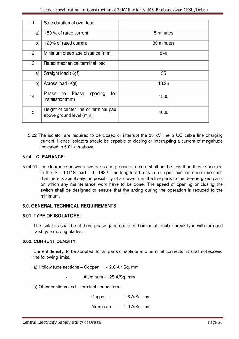
Tender Specification for Construction of 33kV line for AIIMS, Bhubaneswar, CESU/Orissa
Central Electricity Supply Utility of Orissa Page 56
11 Safe duration of over load
a) 150 % of rated current 5 minutes
b) 120% of rated current 30 minutes
12 Minimum creep age distance (mm) 840
13 Rated mechanical terminal load
a) Straight load (Kgf) 35
b) Across load (Kgf) 13.26
14 Phase to Phase spacing for
installation(mm) 1500
15 Height of center line of terminal pad
above ground level (mm) 4000
5.02 The isolator are required to be closed or interrupt the 33 kV line & UG cable line charging
current. Hence isolators should be capable of closing or interrupting a current of magnitude
indicated in 5.01 (iv) above.
5.04 CLEARANCE:
5.04.01 The clearance between live parts and ground structure shall not be less than those specified
in the IS – 10118, part – III, 1982. The length of break in full open position should be such
that there is absolutely, no possibility of arc over from the live parts to the de-energized parts
on which any maintenance work have to be done. The speed of opening or closing the
switch shall be designed to ensure that the arcing during the operation is reduced to the
minimum.
6.0. GENERAL TECHNICAL REQUIREMENTS
6.01. TYPE OF ISOLATORS:
The isolators shall be of three phase gang operated horizontal, double break type with turn and
twist type moving blades.
6.02. CURRENT DENSITY:
Current density, to be adopted, for all parts of isolator and terminal connector & shall not exceed
the following limits.
a) Hollow tube sections – Copper - 2.0 A / Sq. mm
- Aluminum -1.25 A/Sq. mm
b) Other sections and terminal connectors
Copper - 1.6 A/Sq. mm
Aluminum- 1.0 A/Sq. mm
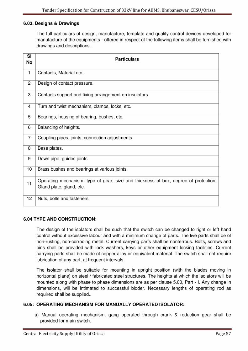
Tender Specification for Construction of 33kV line for AIIMS, Bhubaneswar, CESU/Orissa
Central Electricity Supply Utility of Orissa Page 57
6.03. Designs & Drawings
The full particulars of design, manufacture, template and quality control devices developed for
manufacture of the equipments - offered in respect of the following items shall be furnished with
drawings and descriptions.
Sl
No Particulars
1 Contacts, Material etc.,
2 Design of contact pressure.
3 Contacts support and fixing arrangement on insulators
4 Turn and twist mechanism, clamps, locks, etc.
5 Bearings, housing of bearing, bushes, etc.
6 Balancing of heights.
7 Coupling pipes, joints, connection adjustments.
8 Base plates.
9 Down pipe, guides joints.
10 Brass bushes and bearings at various joints
11 Operating mechanism, type of gear, size and thickness of box, degree of protection.
Gland plate, gland, etc.
12 Nuts, bolts and fasteners
6.04 TYPE AND CONSTRUCTION:
The design of the isolators shall be such that the switch can be changed to right or left hand
control without excessive labour and with a minimum change of parts. The live parts shall be of
non-rusting, non-corroding metal. Current carrying parts shall be nonferrous. Bolts, screws and
pins shall be provided with lock washers, keys or other equipment locking facilities. Current
carrying parts shall be made of copper alloy or equivalent material. The switch shall not require
lubrication of any part, at frequent intervals.
The isolator shall be suitable for mounting in upright position (with the blades moving in
horizontal plane) on steel / fabricated steel structures. The heights at which the isolators will be
mounted along with phase to phase dimensions are as per clause 5.00, Part - I. Any change in
dimensions, will be intimated to successful bidder. Necessary lengths of operating rod as
required shall be supplied..
6.05: OPERATING MECHANISM FOR MANUALLY OPERATED ISOLATOR:
a) Manual operating mechanism, gang operated through crank & reduction gear shall be
provided for main switch.

Tender Specification for Construction of 33kV line for AIIMS, Bhubaneswar, CESU/Orissa
Central Electricity Supply Utility of Orissa Page 58
b) The design of the operating mechanism shall be Such that minimum energy is required for
operation and one person shall be able to operate the switch without undue effort. The blades
shall be in positive continuous control throughout tile entire cycle of operation. Suitable
reduction gear to achieve above aspects may be provided, for main switch and shall close or
open with about 20 revolutions of the crank.
c) The operating pipes and rods shall be sufficiently rigid to maintain positive control without
tension or compression & there shall also be capable of withstanding all torsional and
bending stresses due to operation of the disconnecting switch. It shall not be possible, after
final adjustment has been made for any part of the mechanism to be displaced at any point
in the travel sufficiently to allow improper functioning of the switch, when the switch is
opened or closed at any speed. All holes, ill crank, linkages, etc., having moving pins, shall
be drilled to accurate fit, so as to maintain the minimum amount of slack and lost motion. The
operating mechanism and its controls shall be so designed that under no circumstances the
switch blades travel is interrupted before it reaches the fully close or open position. The
operating mechanism shall be suitable to hold the main switch or earth switch in closed or
opened position to prevent operation by gravity, wind, short circuit, seismic acceleration,
vibration, shock, accidental touching etc.
6.06. CONTROL CABINET:
The operating mechanism mid all accessories shall be enclosed in a weather, dust and
vermin proof cabinet. The control cabinet of each operating mechanism shall be made out of
12 SWG (2.64 mm thick) steel sheet. or 10mm thick aluminum in the form plate or casting.
Control cabinet shall be provided with hinged doors along with padlocking arrangement.
Sloping rain hood shall be provided to cover all sides. 15 mm thick neoprene or better type
gasket shall be provided to ensure degree of protection atleast IP 55 as per S : 2147.
The motor operating mechanism / manually operating mechanism shall be mounted on the
base supporting structures or on a separate Support- structure at a height of 300 mm from the
ground level. Operating or lever for manual operation shall be at a convenient height of 1000
mm above ground level for easy operation. The unsupported length of the operating rod shall
not exceed 3 meters. Guide bearings shall be provided at suitable intervals. All brackets
angles or other members mid accessories necessary for fixing the operating mechanism to
switch supporting structure. and the bearing for operating rods shall be supplied. Rust proof
pins and bearings of the bronze bushing, ball or roller type shall be provided. All ball and roller
bearings shall be protected from weather by means of covers and grease retainers. Bearing
pressures shall be kept low to ensure long life.
6.07 GEAR:
The disconnect may be required to operate occasionally with considerably long idle intervals.
Special care shall be taken for selection of material for gear and lubrication of gears to meet
these requirements. The gears shall be made of bronze or any other better material and
lubricated for life with graphite or better quality non-draining or non-hardening grease.
Complete details of components, materials, self-lubricating arrangement, grade of lubricant,
details of jigs, fixtures and devices used for quality check shall be furnished in the bid.
6.08 CONSTRUCTIONAL FEATURES:
6.08.01 FIXED AND MOVING CONTACTS:
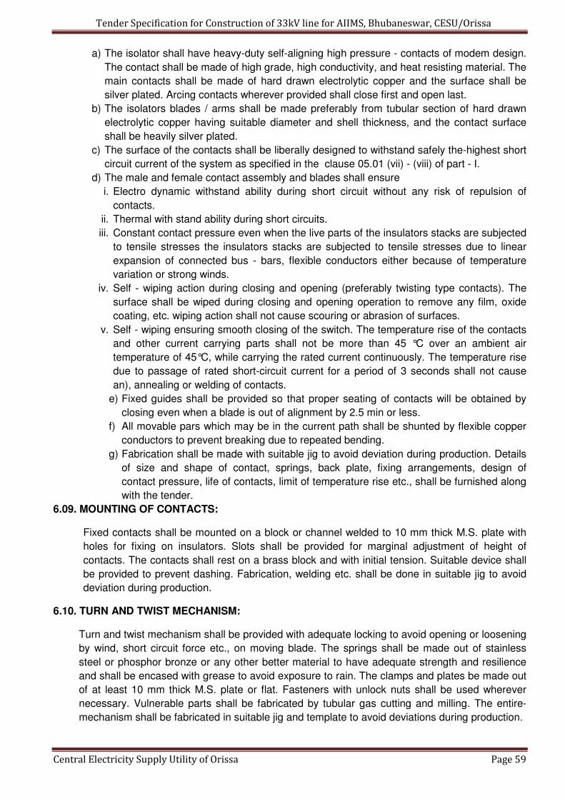
Tender Specification for Construction of 33kV line for AIIMS, Bhubaneswar, CESU/Orissa
Central Electricity Supply Utility of Orissa Page 59
a) The isolator shall have heavy-duty self-aligning high pressure - contacts of modem design.
The contact shall be made of high grade, high conductivity, and heat resisting material. The
main contacts shall be made of hard drawn electrolytic copper and the surface shall be
silver plated. Arcing contacts wherever provided shall close first and open last.
b) The isolators blades / arms shall be made preferably from tubular section of hard drawn
electrolytic copper having suitable diameter and shell thickness, and the contact surface
shall be heavily silver plated.
c) The surface of the contacts shall be liberally designed to withstand safely the-highest short
circuit current of the system as specified in the clause 05.01 (vii) - (viii) of part - I.
d) The male and female contact assembly and blades shall ensure
i. Electro dynamic withstand ability during short circuit without any risk of repulsion of
contacts.
ii. Thermal with stand ability during short circuits.
iii. Constant contact pressure even when the live parts of the insulators stacks are subjected
to tensile stresses the insulators stacks are subjected to tensile stresses due to linear
expansion of connected bus - bars, flexible conductors either because of temperature
variation or strong winds.
iv. Self - wiping action during closing and opening (preferably twisting type contacts). The
surface shall be wiped during closing and opening operation to remove any film, oxide
coating, etc. wiping action shall not cause scouring or abrasion of surfaces.
v. Self - wiping ensuring smooth closing of the switch. The temperature rise of the contacts
and other current carrying parts shall not be more than 45 °C over an ambient air
temperature of 45°C, while carrying the rated current continuously. The temperature rise
due to passage of rated short-circuit current for a period of 3 seconds shall not cause
an), annealing or welding of contacts.
e) Fixed guides shall be provided so that proper seating of contacts will be obtained by
closing even when a blade is out of alignment by 2.5 min or less.
f) All movable pars which may be in the current path shall be shunted by flexible copper
conductors to prevent breaking due to repeated bending.
g) Fabrication shall be made with suitable jig to avoid deviation during production. Details
of size and shape of contact, springs, back plate, fixing arrangements, design of
contact pressure, life of contacts, limit of temperature rise etc., shall be furnished along
with the tender.
6.09. MOUNTING OF CONTACTS:
Fixed contacts shall be mounted on a block or channel welded to 10 mm thick M.S. plate with
holes for fixing on insulators. Slots shall be provided for marginal adjustment of height of
contacts. The contacts shall rest on a brass block and with initial tension. Suitable device shall
be provided to prevent dashing. Fabrication, welding etc. shall be done in suitable jig to avoid
deviation during production.
6.10. TURN AND TWIST MECHANISM:
Turn and twist mechanism shall be provided with adequate locking to avoid opening or loosening
by wind, short circuit force etc., on moving blade. The springs shall be made out of stainless
steel or phosphor bronze or any other better material to have adequate strength and resilience
and shall be encased with grease to avoid exposure to rain. The clamps and plates be made out
of at least 10 mm thick M.S. plate or flat. Fasteners with unlock nuts shall be used wherever
necessary. Vulnerable parts shall be fabricated by tubular gas cutting and milling. The entire-
mechanism shall be fabricated in suitable jig and template to avoid deviations during production.
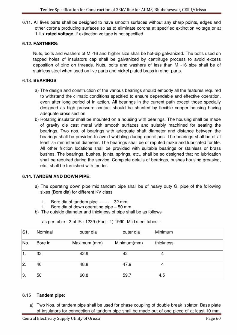
Tender Specification for Construction of 33kV line for AIIMS, Bhubaneswar, CESU/Orissa
Central Electricity Supply Utility of Orissa Page 60
6.11. All lives parts shall be designed to have smooth surfaces without any sharp points, edges and
other corona producing surfaces so as to eliminate corona at specified extinction voltage or at
1.1 x rated voltage, if extinction voltage is not specified.
6.12. FASTNERS:
Nuts, bolts and washers of M -16 and higher size shall be hot-dip galvanized. The bolts used on
tapped holes of insulators cap shall be galvanized by centrifuge process to avoid excess
deposition of zinc on threads. Nuts, bolts and washers of less than M -16 size shall be of
stainless steel when used on live parts and nickel plated brass in other parts.
6.13. BEARINGS
a) The design and construction of the various bearings should embody all the features required
to withstand the climatic conditions specified to ensure dependable and effective operation,
even after long period of in action. All bearings in the current path except those specially
designed as high pressure contact should be shunted by flexible copper housing having
adequate cross section.
b) Rotating insulator shall be mounted on a housing with bearings. The housing shall be made
of gravity die cast metal with smooth surfaces and suitably machined for seating the
bearings. Two nos. of bearings with adequate shaft diameter and distance between the
bearings shall be provided to avoid wobbling during operations. The bearings shall be of at
least 75 mm internal diameter. The bearings shall be of reputed make and lubricated for life.
All other friction locations shall be provided with suitable bearings or stainless or brass
bushes. The bearings, bushes, joints, springs, etc., shall be so designed that no lubrication
shall be required during the service. Complete details of bearings, bushes housing greasing,
etc., shall be furnished with tender.
6.14. TANDEM AND DOWN PIPE:
a) The operating down pipe mid tandem pipe shall be of heavy duty GI pipe of the following
sixes (Bore dia) for different KV class
i. Bore dia of tandem pipe ------- 32 mm. ii. Bore dia of down operating pipe – 50 mm
b) The outside diameter and thickness of pipe shall be as follows
as per table - 3 of IS : 1239 (Part - 1) 1990. Mild steel tubes. -
S1. Nominal outer dia outer dia Minimum
No. Bore in Maximum (mm) Minimum(mm) thickness
1. 32 42.9 42 4
2. 40 48.8 47.9 4
3. 50 60.8 59.7 4.5
6.15 Tandem pipe:
a) Two Nos. of tandem pipe shall be used for phase coupling of double break isolator. Base plate
of insulators for connection of tandem pipe shall be made out of one piece of at least 10 mm.

Tender Specification for Construction of 33kV line for AIIMS, Bhubaneswar, CESU/Orissa
Central Electricity Supply Utility of Orissa Page 61
thick MS plate. Bolt and shackle device shall be used to connect tandem pipe to the base
plate. Wherever unavoidable, sliding clamps may be used. These clamps shall be made out of
at least 10 mm thick MS plate with four(4) nos. of nuts and bolts. A grub screw shall be
provided for securing connection of tandem pipes.
b) The pipe shall be terminated into a suitable swivel or universal type joint between the insulator
bottom bearing of the operating mechanism to take cares of marginal angular misalignment at
site. All brackets, guides, etc., shall be
mounted on the base of the isolator. Arrangement of mounting any guide, bracket, mechanism
and the base shall not be accepted, for upright mounting type isolator.
6.16. BASE :
Each pole of the isolator shall be provided with hot dip galvanized rolled steel base provided
with holes for mounting bolts and designed for mounting on a steel structure. The bases shall
be rigid and self supporting and shall require the guying or cross bracing between phases other
than the supporting structure. The composite frame of the base shall be made of single channel
of 150 x 75 x 6 / 8 mm.
6.17 INSULATORS:
6.17.01.The isolator shall be provided with solid core insulators.
a) These shall be of stacking type to be used.The dimensions and other parameters unless
otherwise specified shall generally conform to IS - 5350-Part-11 & IEC 273.
b) The cylindrical type post insulators shall be of solid core type. Insulators of similar type
shall be interchangeable. The mechanical strength class for outdoor cylindrical post
insulators shall be of strength class 6, corresponding mechanical strength in tension,
compression and torsional shall be as per IS : 53550 Part - II. When operated at
maximum system voltage, there shall be no electrical discharge. Shielding rings, if
necessary shall be provided.
c) The parameters of the insulators required shall conform to IS : 0350 - Part - II - 1973 or
IEC 273.
d) The cylindrical post insulators shall consist of single unit only.
e) The insulator shall be provided with a completely galvanized steel base designed for
mounting on the support. The base and mounting arrangement shall be such that the
insulator shall be rigid and self supporting and no guying or cross bracing between phase
shall be necessary.
6.17.02. Porcelain of the insulator:
a) The porcelain used for the manufacture of the insulators shall be homogenous, free from laminations and other flaws or imperfections that might effect the mechanical or dielectric. quality and shall be thorough vitrified, tough and impervious to moisture. The glazing of the porcelain shall be uniform brown color, with a smooth surface arranged to shade away rain water and free from blisters, burns and other similar defects. Insulators shall be inter-changeable.
b) The porcelain and metal parts shall be assembled in such a manner and with such materials that any differential thermal expansion between the metal and porcelain parts throughout the operating temperature range will not loosen the parts or electrical strength or rigidity. The assembly shall not have excessive concentration of electrical stress in any section or across leakage surfaces. The cement used shall not give rise to chemical

Tender Specification for Construction of 33kV line for AIIMS, Bhubaneswar, CESU/Orissa
Central Electricity Supply Utility of Orissa Page 62
reaction. with metal fittings. The insulator shall be suitable for water washing by rains or artificial means in service conditions. Further the insulators to be supplied shall be of high- quality and should not result in mismatch and misalignment of stacks during erection and operation.
c) Each cap shall be of a high grade cast iron or malleable steel casting or steel forging. Cap and base insulators shall be interchangeable with each other. The insulator shall conform to the requirement of the latest edition of IS : 2544,or any other equivalent standard. The bidder should furnish the characteristics of insulators.
6.17.03 All the ferrous metal part shall be hot dip galvanized smoothly as per IS : 3638 (as amended
up to date), IS : 2623 or any other equivalent authoritative standard. The material shall be
galvanized only after shop operations upon it have been completed. The metal parts for
galvanization should be thoroughly cleaned of any paint, grease, rust, scales or alkalies or
any foreign deposit which are likely to come in the way of galvanization process. The metal
parts coating shall withstand minimum four one minute dips in copper sulphate solution as
per IEC - 168.
The insulator unit shall be assembled in a suitable jig to ensure correct positioning of the top
and bottom metal fittings relative to one another. The phases of the metal fitting shall be
parallel and at right angle to the axis of the
Insulator and corresponding holes in the top and bottom metal fittings shall be in a vertical
plane containing the axis of the insulator.
It shall be sole responsibility of the supplier to carry out thorough inspection and quality,
checks on the insulators at the insulator supplier works before offering the insulators for
purchaser's inspection.
6.18 PADLOCKING DEVICE:
The isolator shall be provided with padlocking device to permit locking of the isolator in both
fully open and fully closed positions.
6.19 EARTHING:
The frame of each disconnect shall be provided with two reliable earthing terminals for
connection to the earthing conductor / flat so also clamping screw suitable for carrying
specified short time current. The diameter of clamping screw shall be at least 12 mm. The
connecting point shall be marked with earth symbol.
6.20 TERMINAL CONNECTORS
a) The disconnecting switches shall be provided with high conductivity bimetallic terminal connectors and suitable for Aluminium pipes (BS 1600 schedule 40) and 100 mm AAA conductors & 120 sqmm U.G.cable, the size of which will be indicated. to successful bidder. The connector shall be rigid in respect of AAA conductors & flexible for UG Cable connections. The terminal connectors shall be expansion type in respect of Aluminium pipes. The terminal connector shall conform to IS : 5561 1970.
b) Further the terminal connectors shall be suitable for both horizontal or vertical take off. c) For bimetallic type of connectors, necessary steps shall be taken by the manufacturers to
ensure that there is no adverse effect on the connector and the connected equipment due to bimetallic action.
6.21. SUPPORTING STRUCTURE:
These galvanized support structures shall be fabricated as per the requirement.

Tender Specification for Construction of 33kV line for AIIMS, Bhubaneswar, CESU/Orissa
Central Electricity Supply Utility of Orissa Page 63
6.22. ASSEMBLY
The disconnect shall be fully assembled at the works of the bidder. Typical operation shall be
carried out on each type of fully assembled disconnect to ascertain that all parts fit correctly and
function satisfactorily.
6.23. PAINTING, GALVANIZING AND CLIMATE PROOFING:
a) All interiors and exteriors of enclosures, cabinets mid other metal parts shall be thoroughly
cleaned to remove all rust scales, corrosions, grease and other adhering foreign matter and
surfaces treated by recognized phosphating (Eg. Seven tank phosphating sequence), After
such preparation of surfaces tow coats of zinc oxide primer shall be given by suitable stoving
and air-drying, etc., before final paint.
b) Colour of the final paint shall be of shade No. 631 of IS-5, i.e., epoxy light grey. The final
painted cubicle shall. present aesthetically pleasing appearance free from any dent of uneven
surface Paint inside the metallic housing shall be of anti - condensation type and the paint on
outside surfaces shall be suitable for outdoor installation.
c) All ferrous parts not suitable for painting such as structural steel, pipes, rods, levers, linkages,
nuts and bolts used in other than current path etc., and also supporting structures shall be hot
dip galvanized. Galvanization shall be done after completion of fabrication which shall be
capable to prevent corrosion in view of the severe climatic conditions.
d) Thickness of zinc coating shall not be less than 610 gm of zinc per sq. meter of surface. Zinc
coating shall be smooth clean and of uniform thickness and free from defect. Preparation of
galvanizing and the galvanizing itself shall not adversely effect the mechanical properties of
the coated material, The quality shall be established by tests per IS : 2633. Galvanizing of nuts
and bolts shall be carried out by centrifugal or suitable process so that the bolts will easily fit
into the tapped holes / nuts.
e) All components shall be given adequate treatment of climate proofing as per IS : 3202 so as to
withstand corrosion and severe conditions.
7.00 TESTS :
7.01Type tests :
a) The equipment offered, shall be fully type tested. The type test reports shall not be older than
5 years on the day of bid opening. The type tests are to conducted again if the reports are
older than 5 years on the day of bid opening at no extra cost to owner.
b) During the type test the disconnect shall be mounted on its own support structure or
equivalent support structure and installed with its own operating mechanism to make the type
test representative. Drawing of equivalent support structure if any and mounting arrangement
made for type tests shall be furnished for purchaser's approval before conducting the type
tests.
c) The type tests shall be conducted on the disconnect along with approved insulators and
terminal connectors.
d) Mechanical endurance test shall be conducted on the main switch.
e) LIST OF TYPE TESTS: List of type tests to be carried out as per IS: 9921 Part - VI 1985, are as given below.
i. Visual examination of components,
ii. Dimensional verification of parts.
iii. Assembly, interchangeability and verification of critical dimensions.
iv. Measurement of resist-circuit of main circuit and earth circuit (before and after
mechanical endurance test)

Tender Specification for Construction of 33kV line for AIIMS, Bhubaneswar, CESU/Orissa
Central Electricity Supply Utility of Orissa Page 64
v. Temperature rise test (before and after mechanical endurance test)
vi. Mechanical endurance test.
vii. Short time withstand current and peak withstand current tests.
viii. One minute power frequency voltage wet withstand tests across the isolating distances
and to earth.
ix. Standard lightning impulse voltage withstands tests on auxilia~3, and control circuits
and auxiliary switches.
x. One minute power frequency, withstand voltage test on auxiliary and control circuits
and auxiliary switch.
xi. Verification of operation during application of rated mechanical terminal loads.
xii. Galvanization tests.
xiii. Chemical composition of contact material, springs and fasteners and bushes.
xiv Physical tests on springs and fasteners and copper strip / tubes.
7.02. ACCEPTANCE AND ROUTING TESTS:
a) All acceptance and routine tests as stipulated in the relevant standards shall be carried out
by the supplier in presence of purchaser's representative.
b) Mechanical operation tests (routine test) shall. be conducted on the complete disconnect
(man switch and earth switch) at supplier's works and a certified test report be furnished to
the purchaser. Alternatively the bidder may offer to conduct this test at purchaser's sub-
station in which case the purchaser shall make necessary arrangement to erect the
disconnect at his sub-station site under supervision of bidders representatives for
supervision shall not be borne
by the purchaser.
c) The test report of power frequency voltage withstand test conducted on the insulator shall
be furnished for purchaser's acceptance in lieu of conducting the power frequency (dry) test
on main circuit (routine test).
d) LIST OF ROUTING TESTS: List. of routine test to be carried out as per IS : 9921, Part - IV - 1985 are as given below:
i. Visual examination of components.
ii. Assembly, interchangeability and verification of critical dimensions.
iii. One minute power frequency voltage dry withstand tests across the isolating distance
and to earth.
iv. Measurement of resistance of isolator contacts and between terminals of the main
circuits.
v. Power frequency voltage withstand tests on auxiliary and control circuits and auxiliary
switches at 2 KV (rms) for one minute.
vi. Mechanical operation tests.
7.03 SPECIAL TESTS
Special tests listed below shall be carried out in presence of purchaser's representative.
a) Test on insulators – Conforming to IS - 2544
b) Test on insulators – Conforming to IEC - 168
c) Test on terminal connecters – IS : 5561
d) Operation tests on operating mechanism - IS : 2623.
e) Test certificates and documents of the following items shall be furnished at the time of
routine tests.

Tender Specification for Construction of 33kV line for AIIMS, Bhubaneswar, CESU/Orissa
Central Electricity Supply Utility of Orissa Page 65
• Chemical analysis of copper.
• Bearings
• Fasteners
• Universal/ swivel joint coupling.
• Insulators.
• Gears
8.00 INSPECTION
The inspection may be carried out by the purchaser at any stage of manufacture. The successful
bidder shall grant free access to the purchaser's representative at a reasonable time when the
work is in progress. Inspection and acceptance of any equipment under this specification by the
purchaser, shall not relieve the supplier of his obligation of furnishing equipment in accordance
with the specification and shall not prevent subsequent rejection if the equipment is found to be
defective. The supplier shall keep the purchaser informed in advance, about the manufacturing
programme so that arrangement can be made for inspection. The purchaser reserves the light to
insist for witnessing the acceptance / routine testing of the bought out items.
9.0. DOCUMENTATION:
All drawings shall conform to International Standard Organization (ISO) ' A ' series of drawing
sheet / Indian standards specification IS : 656. All drawings shall be in ink and suitable for micro
filming. All dimensions and data shall be in system international units.
10.0 LIST OF DRAWINGS AND DOCUMENTS:
The bidder shall furnish the following drawings along with his offer:
a) General outline and assembly drawings of the disconnect, operating mechanism, structure,
insulator and terminal connector.
b) Sectional views and descriptive details of items such as moving blades, contacts arms, contact
springs, contact support, turn and twist mechanism, bearing, housing of bearing, bushes,
balancing of heights, phase coupling pipes, base plate, operating shaft, guides, swivel -joint
operating mechanism and its components, etc.
a) Loading diagram.
b) Drawings with structure for the purpose of type test
c) Name plate
d) Schematic drawing
e) Type test reports in case the equipment has already been type tested
f) Test reports, literature, pamphlets of the bought out items and raw material.
11.0. INSTRUCTION MANUALS
The two copies of the erection, operation and maintenance manuals in English shall be
supplied one month prior to dispatch of the equipment. The manual shall be bound volume and
shall contain all drawings and information required for erection, Operation and maintenance of
the disconnect including but not limited to the following particulars.
a) Marked erection prints identify the component parts of the disconnect as shipped with -
assembly drawings.
b) Detailed dimensions and description of all auxiliaries.
c) Detailed views of the insulator stacks, metallics, operating mechanism, structure etc.

Tender Specification for Construction of 33kV line for AIIMS, Bhubaneswar, CESU/Orissa
Central Electricity Supply Utility of Orissa Page 66
12.0. LIST OF MANUFACTURERS:
a) SWITCHGEAR & STRUCTURAL,
b) MULAR,
c) CGL ,
d) GR POWER ,
e) AREVA,
f) SIEMENS
The bidders can only offer the above manufacturer’s equipments.

Tender Specification for Construction of 33kV line for AIIMS, Bhubaneswar, CESU/Orissa
Central Electricity Supply Utility of Orissa Page 67
Section-VI
Lightning Arrestor

Tender Specification for Construction of 33kV line for AIIMS, Bhubaneswar, CESU/Orissa
Central Electricity Supply Utility of Orissa Page 68
TECHNICAL SPECIFICATION OF 33 KV LIGHTNING ARRESTOR
(VOLTAGE CLASS SURGE ARRESTORS)
The specification covers the design, manufacture, shop & laboratory testing before dispatch,
supply delivery of 33 KV, Station class heavy duty, gapless metal oxide Surge Arrestors,
insulating base, clamps, complete fittings & accessories suitable for 33KV
transformers/feeders including arrester's electrode earthing.
1.0 STANDARDS
The design, manufacture and performance of Surge Arrestors shall comply with IS: 3070
Part-3 and other specific requirement stipulated in the specification Unless otherwise,
specified, the equipment, material and processes shall conform to the latest applicable
Indian/International Standards as listed hereunder:
IS: 2071-1993 (Part-1) : Methods of High Voltage Testing General Definitions & Test Requirements.
IS: 2071-1974 (Part-2) : Test Procedures
IS: 2633-1986 : Methods for Testing uniformity of zinc coated Articles.
IS: 3070-1993 (Part-3) : Specification for surge arrestor for alternating current system Metal-Oxide lightening Arrestors without gaps.
IS:4759-1996 : Specification for hot dip zinc coating on Structural Steel and other allied products.
IS: 5621-1980 : Hollow Insulators for use in Electrical Equipment.
IS: 6209-1982 : Methods of Partial discharge measurement.
IS: 6745-1980 : Methods for determination of mass of zinc coating on zinc coated iron and steel articles.
IEC:TC-37 : Test Procedures.
ANSI/IEEE-C.62.11(1982) : Metal Oxide, Surge Arrestor for A.C. Power Circuits.
IEE-99-4 : Surge Arrestors.
The equipment complying with any other internationally accepted standards shall also be
considered if it ensures performance equivalent to or superior to the India Standards.
2.0 GENERAL REQUIREMENT
2.1 The Metal Oxide gap less Surge Arrestor without any series or shunt gap shall be suitable for
protection of 33 KV power transformers, associated equipment and 33 KV lines from
voltage surges resulting from natural disturbance like lightening as well as system
disturbances.
2.2 The surge arrestor shall draw negligible current at operating voltage and at the same time
offer least resistance during the flow of surge current.
2.3 The surge arrestor shall consist of non-linear resistor elements placed in series and housed
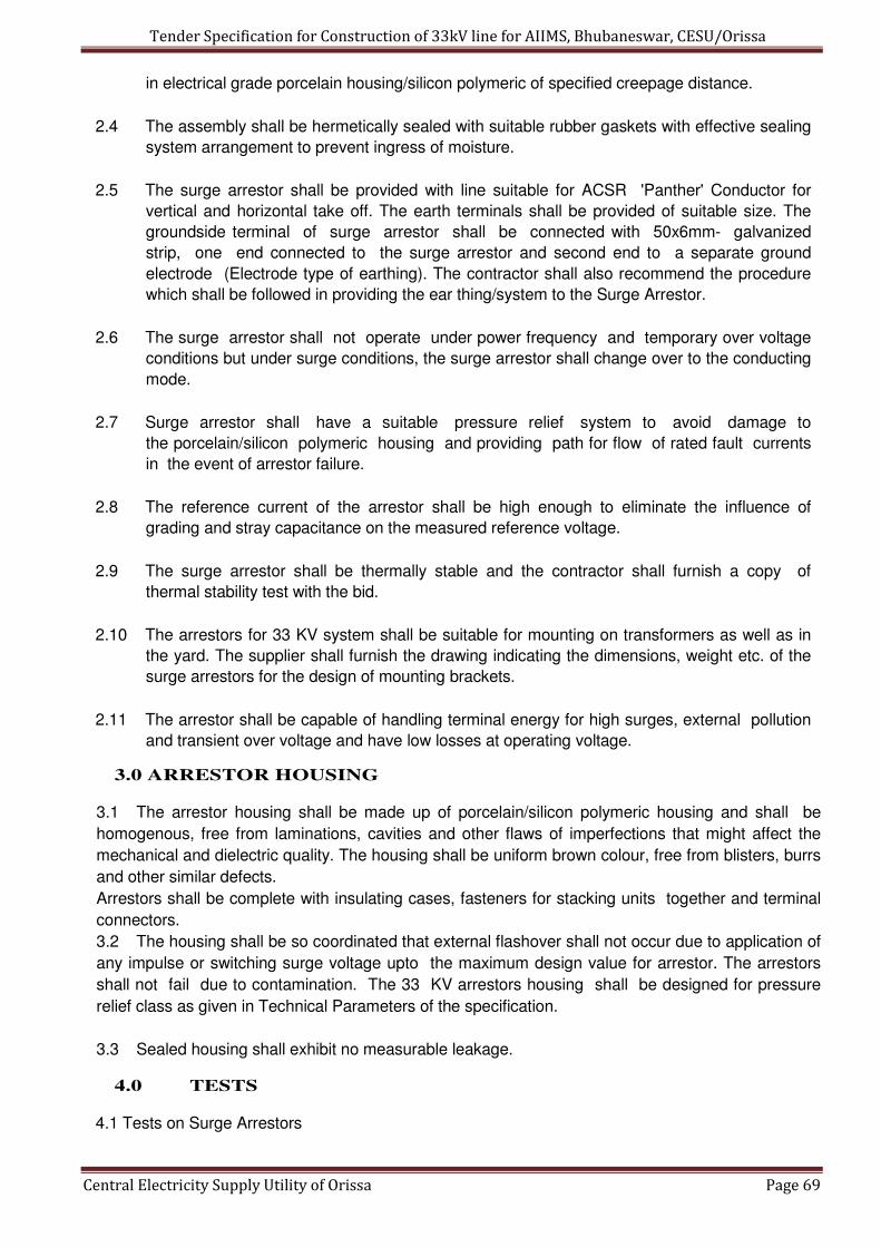
Tender Specification for Construction of 33kV line for AIIMS, Bhubaneswar, CESU/Orissa
Central Electricity Supply Utility of Orissa Page 69
in electrical grade porcelain housing/silicon polymeric of specified creepage distance.
2.4 The assembly shall be hermetically sealed with suitable rubber gaskets with effective sealing
system arrangement to prevent ingress of moisture.
2.5 The surge arrestor shall be provided with line suitable for ACSR 'Panther' Conductor for
vertical and horizontal take off. The earth terminals shall be provided of suitable size. The
groundside terminal of surge arrestor shall be connected with 50x6mm- galvanized
strip, one end connected to the surge arrestor and second end to a separate ground
electrode (Electrode type of earthing). The contractor shall also recommend the procedure
which shall be followed in providing the ear thing/system to the Surge Arrestor.
2.6 The surge arrestor shall not operate under power frequency and temporary over voltage
conditions but under surge conditions, the surge arrestor shall change over to the conducting
mode.
2.7 Surge arrestor shall have a suitable pressure relief system to avoid damage to
the porcelain/silicon polymeric housing and providing path for flow of rated fault currents
in the event of arrestor failure.
2.8 The reference current of the arrestor shall be high enough to eliminate the influence of
grading and stray capacitance on the measured reference voltage.
2.9 The surge arrestor shall be thermally stable and the contractor shall furnish a copy of
thermal stability test with the bid.
2.10 The arrestors for 33 KV system shall be suitable for mounting on transformers as well as in
the yard. The supplier shall furnish the drawing indicating the dimensions, weight etc. of the
surge arrestors for the design of mounting brackets.
2.11 The arrestor shall be capable of handling terminal energy for high surges, external pollution
and transient over voltage and have low losses at operating voltage.
3.0 ARRESTOR HOUSING
3.1 The arrestor housing shall be made up of porcelain/silicon polymeric housing and shall be
homogenous, free from laminations, cavities and other flaws of imperfections that might affect the
mechanical and dielectric quality. The housing shall be uniform brown colour, free from blisters, burrs
and other similar defects.
Arrestors shall be complete with insulating cases, fasteners for stacking units together and terminal
connectors.
3.2 The housing shall be so coordinated that external flashover shall not occur due to application of
any impulse or switching surge voltage upto the maximum design value for arrestor. The arrestors
shall not fail due to contamination. The 33 KV arrestors housing shall be designed for pressure
relief class as given in Technical Parameters of the specification.
3.3 Sealed housing shall exhibit no measurable leakage.
4.0 TESTS
4.1 Tests on Surge Arrestors

Tender Specification for Construction of 33kV line for AIIMS, Bhubaneswar, CESU/Orissa
Central Electricity Supply Utility of Orissa Page 70
The Surge Arrestors offered shall be type tested not earlier than 5 years before the date of
opening of this tender. The surge arrestors shall be subjected to routine and acceptance
tests in accordance with IS: 3070(Part3)-1993. In addition, the suitability of the Surge
Arrestors shall also be established for the following:
* Residual voltage test
* Reference voltage test
* Leakage current at M.C.O.V.
* P.D. Test
* Sealing test
* Thermal stability test
* Aging and Energy capability test
* Watt loss test
Each metal oxide block shall be tested for guaranteed specific energy capability in addition to
routine/acceptance test as per IEC/IS.
4.2 The maximum residual voltages corresponding to nominal discharge current of 10KA for
steep current, impulse residual voltage test, lightning impulse protection level and switching
impulse level shall generally conform to Annexure-K of IEC-99-4.
4.3 The bidder shall furnish the copies of the type tests and the characteristics curves
between the residual voltage and nominal discharge current of the offered surge arrestor and
power frequency voltage V/s time characteristic of the surge arrestor subsequent to impulse
energy consumption as per clause 6.6 of IS: 3070 (Part-3) offered along with the bid.
4.4 The surge arrestors housing shall also be type tested and shall be subjected to routine
and acceptance tests in accordance with IS: 2071.
4.5 Galvanization Test
All Ferrous parts exposed to atmospheric condition shall have passed the type test and be
subjected to routine and acceptance test in accordance with IS: 2633 & IS: 6745.
5.0 NAME PLATE
5.1 The nameplate attached to the arrestors shall carry the following information: -
* Manufacturing Trade Mark
* Year of Manufacture
* Rated Voltage
* Continuous Operation Voltage
* Pressure relief rated current
* Name of Client-
* Purchase Order Number along with date.
6.0 INSPECTION
6.1 All tests and inspection shall be made in the manufacturer’s works unless
otherwise specifically agreed upon by the manufacturer and purchaser at the time of
placement of purchase order. The manufacturer shall afford to the inspector representing the
purchaser, al reasonable facilities, without charge to satisfy him that the material being
furnished is in accordance with these specifications. The purchaser reserves the right to get
an component/material being used by the manufacturer of the Surge Arrestor tested from
Tender Specification for Construction of 33kV line for AIIMS, Bhubaneswar, CESU/Orissa
Central Electricity Supply Utility of Orissa Page 71
any recognized test house.
6.2 The inspection by the purchaser or his authorized representative shall not relieve
the contractor of his obligation of furnishing equipment in accordance with the specifications.
7.0 DRAWING AND INSTRUCTION MANUALS
Within 15 days of receipt of the order, the successful tenderer shall furnish to the
purchaser the following drawings and literature for approval:
a. Outline dimensional drawings of Surge Arrestor and all accessories. b.
Assembly drawings and weights of main component parts.
c. Instructions manual
d. Drawing showing details of pressure relief value
e. Volt-time characteristics of surge arrestors.
f. Detailed dimensional drawing of porcelain housing/ Silicon polymeric
i.e. internal diameter, external diameter, thickness, height profile, creepage
distance, dry arching distance etc.

Tender Specification for Construction of 33kV line for AIIMS, Bhubaneswar, CESU/Orissa
Central Electricity Supply Utility of Orissa Page 72
GURANTEED TECHNICAL PARTICULARS FOR
33 KV LIGHTNING ARRESTOR
(To be submitted along with offer)
Sl. No. Particulars Bidder’s Offer
1. Name of manufacturer.
2. Type Designation
3. Model (Drawing No.)
4. Applicable Standard
5. No. of units per Arrestors
6. Rated Voltage
7. Nominal discharge current 8/20
micro second wave (KA)
8. Maximum continuous operating Voltage
9. Insulation withstand voltage
power frequency.
10. Maximum Lightning Impulse
Residual voltage (8/20 micro
second wave
11. Maximum steep current Impulse Residual voltage at 10 KA of micro second front time.
12. Maximum Switching Impulse Residual voltage 50 x 100 micro seconds at 500 Amps.
13. Current Impulse withstand capability.
i) Long duration discharge class.
ii) Minimum energy discharge capability
14. Protective Ratio
15. High current impulse withstand value (4 x10 Micro seconds)
16. Pressure relief class.
i) High current
ii) Low current
17. Reference current of the arresters Ambient
18. Current at M.C.O.V. (Maximum Continuous
i) Resistive Current IR
ii) Capacitive voltage IC
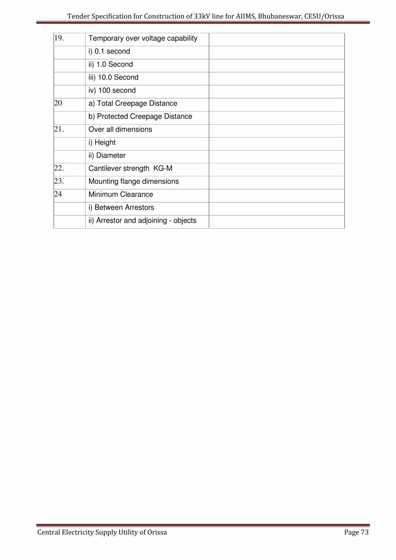
Tender Specification for Construction of 33kV line for AIIMS, Bhubaneswar, CESU/Orissa
Central Electricity Supply Utility of Orissa Page 73
19. Temporary over voltage capability
i) 0.1 second
ii) 1.0 Second
iii) 10.0 Second
iv) 100 second
20 a) Total Creepage Distance
b) Protected Creepage Distance
21. Over all dimensions
i) Height
ii) Diameter
22. Cantilever strength KG-M
23. Mounting flange dimensions
24 Minimum Clearance
i) Between Arrestors
ii) Arrestor and adjoining - objects

Tender Specification for Construction of 33kV line for AIIMS, Bhubaneswar, CESU/Orissa
Central Electricity Supply Utility of Orissa Page 74
Section-VII
33kV HT UG Cable

Tender Specification for Construction of 33kV line for AIIMS, Bhubaneswar, CESU/Orissa
Central Electricity Supply Utility of Orissa Page 75
TECHNICAL SPECIFICATIONS FOR 33kV XLPE INSULATED UNDERGROUND CABLES
1.0 SCOPE :
1.1 The scope of this specification covers the design, manufacture, stage inspection at works,
inspection and testing the finished cables 33kV aluminum conductor. Three Core 400 mm²
and 300 mm², XLPE insulated screened, dry cured Power cables for use with effectively
earthed urban distribution system at manufacturer’s works. One portion from 33/11kV s/s to
AIIMS Bhubaneswar is proposed for 3 core 400 mm², XLPE insulated Cable and the rest
cable portion is proposed for 3 core, 300 mm², XLPE insulated as per the SLD given
herewith.
2.0 RATED VOLTAGE
2.1 The rated voltage of the cable shall be 33000 Volts AC with the highest system voltage of
36000 Volts between phases of the effectively earthed three phase-distribution system.
3.0 APPLICABLE STANDARDS:
3.1 Unless otherwise stipulated in the specifications, the latest version of the following
Standards shall be applicable.
a. IS 8130 – Conductors for Insulated electrical cables and flexible cords, H4
Grade Aluminium Conductor, Stranded compacted Circular.
b. IS 10810 (series) – Methods of tests for cables.
c. IS 10418 – Drums for electrical cables.
d. IS 7098 (Part 2) – Cross – linked Polyethylene Insulation for Cables.
e. IS 3975 – Specification for mild steel wires, strips and tapes for armoring of
cables.
f. IS 5831 – Specification for PVC insulation sheath for electric cables.
Dimensions of protective coverings of cables
Part 1 – Elastomeric and thermoplastic insulated cables.
3.2 The Cables manufactured to any other Internal Standards like BSS, IEC or equivalent
standards not less stringent than Indian Standards are also acceptable. In such cases, the
Bidders shall enclose a copy of the equivalent international standard, in English language,
along with the bid.
4.0 CLIMATIC CONDITIONS:
• Maximum temperature of air in shade : 50 Degree C
• Minimum temperature of air in shade : 15 Degree C
• Maximum temperature of air in sun : 65 Degree C
• Maximum humidity : 87%
• Average No. of thunder storm days per annum : 50
• Average No. of dust storm days per annum : 10
• Maximum rainfall per annum : 3000 mm

Tender Specification for Construction of 33kV line for AIIMS, Bhubaneswar, CESU/Orissa
Central Electricity Supply Utility of Orissa Page 76
• Average rainfall per annum : 925 mm
• Limits of ambient temperature over a period of 24hours: 47Deg. C and 27Deg. C in summer and 30Deg. and 7.5Deg.C during winter
• Maximum wind pressure : 260Kg/Sq.mm
• Altitude : 1000M above MSL
5.0 PRINCIPAL PARAMETERS:
• The Power cable shall be 33 KV grade high conductivity stranded,
compacted, aluminum shaped conductor of flexibility grade-2, 3 core dry cured XLPE
insulated, extruded inner PVC sheathed, galvanized steel strip armored, with
separate extruded PVC outer sheathed overall, conforming generally to IS:7098
(Part-II/1985) or any latest amendment there of suitable for 33 KV / 11 KV 3 Phase 50
C/S earthed system.
• CONDUCTOR: The cable conductor shall be made from stranded aluminum to
form compact shaped conductor having resistance within the limits specified in IS:
8130/1984 and any amendment thereof. The wires shall be laid up together with a
suitable right hand lay.
• CONDUCTOR SHIELD: The conductor having a non-magnetic semi- conducting
screen shall ensure perfectly smooth profile and avoid stress concentration. This
conductor screen shall be extruded in the same operation as the insulation; the semi-
conducting polymer shall be cross linked.
• INSULATION: The XLPE insulation should be suitable for specified 33 KV system
voltages. The curing process of XLPE insulation should be dry cured. The
manufacturing process shall ensure that insulations shall be free from voids. The
insulation shall withstand mechanical and thermal stresses under steady state and
transient operating conditions. The extrusion method should give very smooth
interface between semi- conducting screen and insulation. The insulation of the cable
shall be high stranded quality, specified in IS:7098 (Part-II/1985).
• INSULATION SHIELD: To confine electrical field to the insulation, non- magnetic
semiconducting shield shall be put over the insulation. The insulation shield shall be
extruded in the same operation as the conductor shield and the insulation by triple
extrusion process. The XLPE insulation shield should be strippable. Metallic
screening shall be provided.
• SHEATH: The sheath shall be suitable to withstand the site conditions and the
desired temperature. It should be of adequate thickness, consistent quality and
free from all defects. The PVC sheath shall be extruded as per IS: 7098 Part-II/1985.
• ARMOUR: Armoring shall be applied over the inner sheath with single
galvanized steel wire/strip complying with the requirements of IS: 3975/1979. The

Tender Specification for Construction of 33kV line for AIIMS, Bhubaneswar, CESU/Orissa
Central Electricity Supply Utility of Orissa Page 77
dimensions of the galvanized wire/strip shall be as specified in table 4 of the IS:
7098/Part-II/1985. The armour wire/strips shall be applied as closely as practicable.
The direction of the lay of the armour shall be left hand. The joints in armour
wire/strip shall be made by brazing or welding and the surface irregularities shall be
removed. A joint in any wire/strip shall be at least 300mm from the nearest joint in
any other armour wire/strip in the complete cable.
• OUTER SHEATH: Extruded PVC outer sheath as per IS:5831/1984, shall be
applied over armouring with suitable additives to prevent attack by rodents and
termites. Outer sheathing shall be designed to offer high degree of mechanical
protection and shall also be heat, oils, chemicals, abrasion and weather resistant.
Common acids, alkalis, saline solutions etc., shall not have adverse effects on the
PVC sheathing material used. The cable shall be suitable for laying in covered
trenches and/or buried underground to meet the outdoor application purposes.
• Conductor Screening: Extruded, cross-linked, semi-conducting compound of 1.0mm thickness for 33 KV
6.0 CONSTRUCTION:
• The cable shall have suitable PVC fillers laid up with insulation cores to provide
substantially circular cross section before the inner sheath is applied. The fillers should be
suitable for the operating temperature of the cable and compatible with the insulating material.
• All materials used in the manufacture of cable shall be new, unused and of finest quality. All
materials should comply with the applicable provisions of the tests of the specification, IS,
Indian Electricity Rules, Indian Electricity Act and any other applicable statutory provisions,
rules and regulations.
• The PVC material used in the manufacture of cable should be of reputed manufacturer. No
recycling of the PVC is permissible. The purchaser reserves the right to ask for
documentary proof of the purchase of various materials to be used for the manufacture of
cable and to check that the conductor is complying with quality control.
• Maximum Permissible emergency overload temp. at 25% overload to 100 hrs. per year or
500 hrs. in life of cable :1300C for 1 hour.
• Maximum Permissible short circuit temperature: 2500 C for 1 hour.
7.0 CURRENT RATING:
The cables will have current ratings and derating factors as per relevant Indian
Standards. The one second short circuit current rating values shall be furnished and shall
be subject to the purchaser’s approval. The current ratings shall be based on maximum
conductor temperature of 90Deg.C with ambient site condition specified for continuous
operating at the rated current. The Short circuit current rating should be 28.2 KA for 1sec for
33 KV, 300 mm2 and 37.6 KA for 1 sec. for 33 KV, 400 mm2, XLPE UG Cable.
Tender Specification for Construction of 33kV line for AIIMS, Bhubaneswar, CESU/Orissa
Central Electricity Supply Utility of Orissa Page 78
8.0 OPERATION
Cables shall be capable of satisfactory operation, under a power supply system frequency
variation of plus or minus 3 Hz., voltage variation of plus or minus 10% and combined
frequency voltage variation of 10% (absolute sum). Cable shall be suitable for laying in ducts
or burried under ground. Cable shall have heat and moisture resistance properties. These
shall be of type and design with proven record on Distribution Net work services.
9.0 LENGTHS:
The cables shall be supplied in standard drum lengths of 250Mtr. ±5% for 33 KV Cables.
10.0 IDENTIFICATION:
For identification of individual cores, colored tape of red, yellow and blue colors
respectively shall be used on the cores on frequent intervals to identify phase
conductors as per IS:7098/Part-II/1985.
• MARKING ON THE DRUM: The following information either stenciled on the reel
or drum or contained in a label attached to it shall be carried by the cable.
� Reference : IS:7098/Part-II
� Manufacturers Name, Brand name or Trade mark
� Type of cable and voltage grade
� Number of cores
� Nominal cross sectional area of conductor
� Cable code
� Length of cable on the reel or drum
� Number of lengths on the reel or drum
� Direction of rotation of drum (by means of arrow)
� Approximate gross weight
� Year of manufacture
� The reel, drum, or label may be marked with IS Certification mark
� The drum shall be marked ―Name of Bayer – CESU, Orissa.
� Purchase Order number and date.
• EMBOSSING ON THE OUTER SHEATH OF CABLE:
Each cable shall have the range of non-erasable distinct markings listed below
legibly printed on its outer sheath at one meter intervals.
� ISI Mark with B.I.S License No. & ISS No. Applicable legibly embossed on
the insulation.
� Buyer’s name : “CESU, Orissa”
� Manufacturer’s Name with trademark identification.
� Year of manufacture: last two digits are sufficient:

Tender Specification for Construction of 33kV line for AIIMS, Bhubaneswar, CESU/Orissa
Central Electricity Supply Utility of Orissa Page 79
� Size of Cable
� Rated voltage class:
� Sequential marking of length.
� The height of the printed lettering shall be not less than 20% of the overall
diameter of the conductor
11.0 TESTS The following tests shall be carried out in accordance with IS:8130/1984, IS:3975/1979
(Armouring), IS:5831/1984, IS:10810 (Methods of test for cables), IS:7098/Part-II/1985.
• TYPE TESTS: The following shall constitute the type tests :
� Tensile test (for aluminum) in accordance with IS:8130/1984.
� Wrapping test (for aluminum) in accordance with IS:8130/1984.
� Conductor resistance tests (in accordance with IS:8130/1984)
� Test for thickness of insulation and sheath (in accordance with IS:10810)
� Physical test for insulation and sheath (in accordance with IS:10810 and IS:
5831/1984).
� Test for bleeding and blooming of pigments (in accordance with
IS:5831/1984)
� Insulation resistance test (in accordance with IS:5831/1984)
� High voltage test (water immersion test) in accordance with IS:10810.
• ACCEPTANCE TESTS: The following shall constitute the acceptance tests:
� Tensile test (for aluminum): IS:8130/1984
� Wrapping test (for aluminum): IS:8130/1984
� Conductor resistance test : IS:8130/1984
� Test for thickness of insulation: IS:5831/1970 & IS:10810
� Insulation resistance test: IS:5831/1970 & IS:10810
� Partial discharge test: IS: 7098/part-II/1985.
• ROUTINE TESTS: The following shall constitute routine tests:
� Conductor resistance test (in accordance with IS: 8130/1984)
� High voltage test or spark test (in accordance with IS: 10810)
12.0 INSPECTION
All acceptance tests shall be conducted at the time of inspection and inspection shall be
made at the place of manufacture unless and otherwise specifically agreed upon by the
manufacturer and purchaser at the time of purchase. The manufacturer shall afford the
inspector representing the purchaser all reasonable facilities, without charges to satisfy him

Tender Specification for Construction of 33kV line for AIIMS, Bhubaneswar, CESU/Orissa
Central Electricity Supply Utility of Orissa Page 80
that the material is being furnished in accordance with the specification. The purchaser has
the right to have the test carried out at his own cost by an independent agency whenever
there is dispute regarding the quality of supply.
13.0 PACKING
The cable shall be either wound on reels or drums, the packing shall be robust enough for
rough handling that is occasioned during transportation by Rail/Road.
14.0 GUARANTEED TECHNICAL PARTICULARS:
Guaranteed technical particulars of the cables to be furnished with the Bid are enclosed.
15.0 DRAWING & LITERATURE
15.1 The following shall be furnished along with the tender
a) Cross sectional drawings of the cables, giving dimensional details for each size of
cable.
b) An illustrated literature on the cable, giving technical technical information, on
current ratings, cable constants, short circuit ratings, derating factors, for different
types of installation, packing date, weights and other relevant information.
16.0 Schedule of Requirement, Desired deliveries and Prices
The schedule of requirement and desired deliveries etc. are indicated in the GTP.
17.0 INSTALLATION CONDITIONS a) UG Cables are laid in open trench & Brick masonry work with slab in usual
conventional methods, on bedding free from large stones, pieces of rocks, etc.,
Cable trench should be 1meter width x 1meter depth, with RCC cover. Rack
arrangement with 65x65x6 angle for laying of cable & sand filling for the protection
of cable as per IS 1255-1983. And cable should drawn in pipes of ducts wherever
necessary. For Nature of soil is heterogeneous, sandy, Soil resistivity varies
between 18 to 100 ohmmeter and the Thermal resistivity is around 1200 to 1500 C/
Cm/w. Only firm prices shall be quoted.
18.0 QUANTITY
Tenderer may quote the quantity that they can offer immediately within a month of the issue
of purchase order and the minimum time required to supply the full quantity.
• ISI CERTIFICATION: Tenderer having ISI certification marking will only be
considered.
• DRAWING & LITERATURE: The following shall be furnished along with the
tender
� Cross sectional drawings of the cables, giving dimensional details for each size
Tender Specification for Construction of 33kV line for AIIMS, Bhubaneswar, CESU/Orissa
Central Electricity Supply Utility of Orissa Page 81
of cable.
� An illustrated literature on the cable, giving technical information, on
current ratings, cable constants, short circuit ratings, de-rating factors, for
different types of installation, packing date, weights and other relevant information.
19.0 LIST OF MANUFACTURERS: a) NICO
b) GLUSTER
c) POLYCAP
d) DIMOND
e) FINOLEX
f) KEI
The bidders can only offer the above cable manufacturer’s equipments. However manufacturers
other than the above list may be considered based on their previous experience and approval of
CESU.

Tender Specification for Construction of 33kV line for AIIMS, Bhubaneswar, CESU/Orissa
Central Electricity Supply Utility of Orissa Page 82
GURANTEED TECHNICAL PARTICULARS TO BE
FURNISHED BY THE BIDDER
1. CABLES a) Manufacturer b) Trade Name
2. Type of Cable 3. Applicable specification & Standards 4. Voltage Class 5. Whether suitable for extrusion technique is employed in the manufacture of conductor screen 6. Whether triple extrusion technique is employed in the manufacture of conductor screen 7. Permissible voltage and frequency variation for satisfactory operation 8. Continuous Current Rating for standard conditions indicated in specifications:
c) Air (45
0 C Ambient)
d) In Ground (350 C)
e) In Duct f) In Trench
9. De-rating factors for various laying conditions 10. Conductor
a) Material b) Shape of conductor c) Nominal area of cross section d) Number of strands per core e) Diameter of Wire (before compacting and stranding) f) Diameter and size of conductor
11. Conductor Screening a) Type b) Material c) Nominal thickness d) Continuos working temperature e) Maximum allowable temperature at the termination of short circuit
12. Insulation a) Material b) Thickness of Insulation c) Thickness of Insulation between cores d) Thickness of Insulation between cores and inner sheath e) Tolerance of thickness in insulation f) Diameter of core over insulation
13. Specific Insulation Resistance at 900C
14. Process of curing 15. Whether XLPE Insulation filled or unfilled 16. Insulation Screening:
a) Material b) Thickness c) Thickness of semi conducting part d) Thickness of metallic part e) Size of copper tape f) Whether overlapping provided g) Current carrying capacity for continuous rating h) Current carrying capacity for short circuit rating for 1 minutes
i) Diameter of cable over screening j) Whether insulation screen is removable without the application of heat
17. Inner Sheath
a) Material b) Extruded or wrapped c) Minimum thickness d) Diameter of cable over inner sheath

Tender Specification for Construction of 33kV line for AIIMS, Bhubaneswar, CESU/Orissa
Central Electricity Supply Utility of Orissa Page 83
18. Armouring: a) Material b) Type of Armouring c) Diameter of wire d) Whether galvanized e) Diameter of cable over Armouring f) Current carrying capacity of Armor
19. Outer Sheath: a) Material b) Minimum thickness of sheath c) Tolerance over thickness of sheath d) Overall diameter of cable
20. Scheme for identification of cable 21. Allowable/attainable maximum conductor temperature when carrying rated current continuously 22. Cable constants:
a) DC Resistance per core 200 C
b) AC Resistance per core at operating temperature c) Reactance d) Capacitance e) Insulation Resistance at 27
0C
f) Loss tangent g) Dielectric constant – Maximum cable charging current at normal operating voltage
23. Factory Tests (Enumerate in detail for each type of cable) 24. Is the offered cable guaranteed to safely withstand continuous conductor temperature at 90
0C and
also safely withstand temperature upto 1300C for a duration of one hundred hours per year.
25. Are the offered Three core cable guaranteed to perform satisfactorily under installation conditions specified? If ‘Yes’ furnish relevant calculations in support including the following data: a) Induced voltage in the Amour when a 500 mtr long cable is carrying current b) Induced voltage and the circulating current in the copper tape
Tender Specification for Construction of 33kV line for AIIMS, Bhubaneswar, CESU/Orissa
Central Electricity Supply Utility of Orissa Page 84
Section-VIII
HT cable joints and terminals

Tender Specification for Construction of 33kV line for AIIMS, Bhubaneswar, CESU/Orissa
Central Electricity Supply Utility of Orissa Page 85
TECHNICAL SPECIFICATIONS FOR HEAT SHRINKABLE CABLE JOINT KITS FOR
CABLE TERMINATIONS AND JOINTS
1.0 GENERAL:
1.1 The term heat shrink refers to extruded or molded polymeric materials which are cross linked to
develop elastic memory and supplied in expanded or deformed size or shape. The manufacturer of
kits besides stating the properties of each component of the kit as indicated below and as per the
detailed specifications should also state the source of origin of each component viz; whether locally
manufactured or imported in raw material form and processed. The manufacturing activity carried out
on each component should be stated. Also, in case the kit is assembled with components imported
from two or more foreign suppliers, the manufacturers should give documentary proof supported by
the foreign manufacturers confirming that the kit assembled utilizing components of different
suppliers are guaranteed by them.
2.0 QUALIFYING EXPERIENCE:
2.1. The kits should have satisfactory performance record in India in excess of 5 years supported
with proof of customers having had satisfactory use of these kits in excess of 5 years.
3.0 HEAT SHRINKABLE MATERIAL:
3.1. The heat shrinkable material component used in the joint shall have been produced in a
systematic procedure as follows:
a) The required materials shall be mixed and extruded into the required shape and then cross-
linked by irradiation or any other appropriate chemical process. The components are then
warmed and stretched by a predetermined amount and allowed to cool in the extruded
shape. The cross-linking shall create a memory and when heated again, the same shall
come back to its original shape at which it was cross-linked. Heat shrinkable tubes can be
reduced to 30% of its expanded dimension by heating.
b) The volume resistivity of the sleeves shall be 108 ohm-cm and the dielectric constant of
around 15 to 30. The limiting temperature shall not be less than 100°C for longer duration
and 250°C for one minute.
4.0 TYPE TEST REPORTS:
The Joints and terminations should have been subjected to all the type tests and type test
reports not later than 5 years on the day of Bid opening shall be furnished for verification.
5.0 ELECTRICAL CLEARANCES:
The electrical clearances required for a Indoor/Outdoor termination and a straight through
joint is shall be as per standards
6.0 COMPRESSION TYPE TUBULAR TERMINAL ENDS:
The materials used in the terminals shall be Aluminum of grade 19501 conforming to IS
5082 - Specifications for wrought aluminum and aluminum alloys bars, rods, tubes and
sections for electrical purposes. The finish inside the barrel shall either be suitably
roughened throughout the crimping length of terminal end or provided with suitable grease
based compound with abrasive action. Edges and corners shall be free from burrs and sharp
Tender Specification for Construction of 33kV line for AIIMS, Bhubaneswar, CESU/Orissa
Central Electricity Supply Utility of Orissa Page 86
edges. The terminals shall meet the requirements of IS 8309 - Specification for Compression
type tubular terminal ends for aluminum conductors of insulated cables.
7.0 JOINT KITS:
The requirements contained in a typical joint Kit are as follows:
a) Heat shrinkable or push-on or Tapex or cold shrinkable type clear
insulating tubes
b) Stress control tubing where necessary
c) Ferrule insulating tubing for joints.
d) Conductive cable break outs for terminations, non tracking, erosion and
e) Weather resistant tubing both outer / inner
f) Non tracking erosions and weather resistant outdoor sheds in case of
terminations
g) High permittivity mastic wedge Insulating mastic.
h) Aluminum crimping lugs of ISI specification.
i) Tinned copper braids
j) Wrap around mechanical protection for joints.
k) Cleaning solvents, abrasive strips.
l) Plumbing metal.
m) Binding wire etc. adequate in quantity and dimensions to meet the service
and test conditions.
n) The kit shall contain a leaflet consisting of detailed installation instructions and shall be
properly packed with shelf life of over 3 years.
8.0 LIST OF MANUFACTURERS:
a) RECHEM
b) FRONTECH
c) 3M
The bidders can only offer the above manufacturer’s equipments.

Tender Specification for Construction of 33kV line for AIIMS, Bhubaneswar, CESU/Orissa
Central Electricity Supply Utility of Orissa Page 87
ANNEXURE - I
SPECIFICATIONS FOR MATERIAL PROPERTIES AND OTHER TECHNICAL REQUIREMENTS FOR HEAT SHRINKABLE CABLE TERMINATIONS AND JOINTS SUITABLE FOR 33 kV SCREENED CABLES/XLPE CABLES
1.0 GENERAL:
The term heat shrink refers to extruded or molded polymeric materials which are cross linked
to develop elastic memory and supplied in expanded or deformed size or shape. The
subsequent heating results in shrinking down to original size and shape. The manufacturer of
kits besides stating the properties of each component of the kit as indicated below and as per
the detailed specifications given in Enclosures-I(A), I(B) & I(C) should also state the source of
origin of each component viz; whether locally manufactured or imported in raw material form
and processed. The manufacturing activity carried out on each component should be stated.
Also, in case the kit is assembled with components imported from two or more foreign
suppliers, the manufacturers should give documentary proof supported by the foreign
manufacturers confirming that the kit assembled utilizing components of different suppliers are
guaranteed by them.
2.0 QUALIFYING EXPERIENCE:
The kits should have satisfactory performance record in India in excess of 5 years supported
with proof of customers having had satisfactory use of these kits in excess of 5 years.
3.0 PERFORMANCE TESTING AT CPRI, BANGALORE:
The successful contractor/bidder should undertake the testing of termination and jointing kits at CPRI
in the presence of CESU Engineers as per the performance type test sequence given below. For this
purpose, the kit shall be selected by CESU Engineers in the manufacturer’s premises and sealed by
the Engineer before taking it to CPRI, Bangalore.
Typical atmospheric conditions during the tests
Sl No Particulars Details
Maximum 450 C 1 Amb. Temperature
Minimum 100 C
2 Atmospheric pressure 963 to 987 m. bar
3 Relative Humidity 50 – 90 %
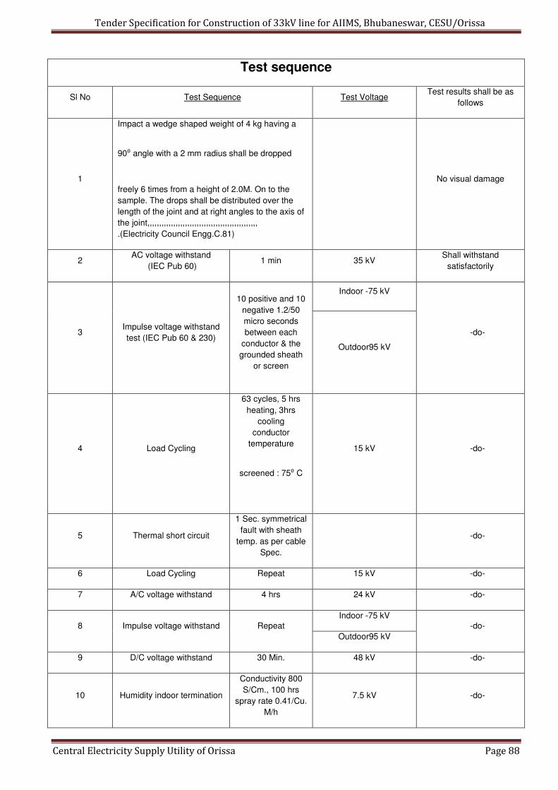
Tender Specification for Construction of 33kV line for AIIMS, Bhubaneswar, CESU/Orissa
Central Electricity Supply Utility of Orissa Page 88
Test sequence
Sl No Test Sequence Test Voltage Test results shall be as
follows
1
Impact a wedge shaped weight of 4 kg having a
90⁰ angle with a 2 mm radius shall be dropped
freely 6 times from a height of 2.0M. On to the
sample. The drops shall be distributed over the
length of the joint and at right angles to the axis of
the joint,,,,,,,,,,,,,,,,,,,,,,,,,,,,,,,,,,,,,,,,,,,,,,,
.(Electricity Council Engg.C.81)
No visual damage
2 AC voltage withstand
(IEC Pub 60) 1 min 35 kV
Shall withstand
satisfactorily
Indoor -75 kV
3 Impulse voltage withstand
test (IEC Pub 60 & 230)
10 positive and 10
negative 1.2/50
micro seconds
between each
conductor & the
grounded sheath
or screen
Outdoor95 kV
-do-
4 Load Cycling
63 cycles, 5 hrs
heating, 3hrs
cooling
conductor
temperature
screened : 75⁰ C
15 kV -do-
5 Thermal short circuit
1 Sec. symmetrical
fault with sheath
temp. as per cable
Spec.
-do-
6 Load Cycling Repeat 15 kV -do-
7 A/C voltage withstand 4 hrs 24 kV -do-
Indoor -75 kV
8 Impulse voltage withstand Repeat
Outdoor95 kV
-do-
9 D/C voltage withstand 30 Min. 48 kV -do-
10 Humidity indoor termination
Conductivity 800
S/Cm., 100 hrs
spray rate 0.41/Cu.
M/h
7.5 kV -do-

Tender Specification for Construction of 33kV line for AIIMS, Bhubaneswar, CESU/Orissa
Central Electricity Supply Utility of Orissa Page 89
ENCLOSURE – I (A)
MATERIAL SPECIFICATION FOR HEAT SHRINKABLE TUBING
Requirement
Test Test
Method Non-Tracking
Tubing
Stress
Control
Tubing
Ferrule
insulating
tubing
Clear insulating
tubing
Inner
Outer
tubing for
Joint
Tensile
Strength ISO 37
8 N/mm²
Min.
14 N/mm²
Min.
10 N/mm²
Min.
12 N/mm²
Min.
14 MPa
Min.
Ultimate
Elongation
ISO 37
300 %
Min.
250 %
Min.
300 %
Min.
200 %
Min.
500 %
Min.
Accelerate
d Ageing
168 Hrs. at
120⁰C
ISO 188
-Tensile
Strength
ISO 37
Min.
7.5 N/mm²
Min.
13 N/mm²
Min.
10 N/mm²
Min.
12 N/mm²
Min.
14 MPa
Min.
-
Ultimate
Elongation
ISO 37
200 %
Min.
130 %
Min.
300 %
Min.
200 %
Min.
300 %
Min.
Thermal
Endurance
IEC 216
110⁰ C
Min.
90⁰ C
Min.
105⁰ C
Min.
110⁰ C
Min.
120⁰ C
Min.
Electric
Strength
IEC 243
Wall Elec.
Thkn. Strn.
(Normal) KV/CM
- Wall Elec.
Thkn. Strn.
(Normal)KV/CM
Wall Elec.
Thkn. Strn.
(Normal)KV/CM
100
kV/CM
Min.
3.0 100
mm. Min.
3.0 100
mm. Min.
*1.3 100
mm. Min.
11 Dynamic short circuit
(VDE 0278) 63 kA -do-
12 Salt frog outdoor
terminations 224 Kg/m³ 7.5 kV -do-

Tender Specification for Construction of 33kV line for AIIMS, Bhubaneswar, CESU/Orissa
Central Electricity Supply Utility of Orissa Page 90
Volume
Resitivity
IEC 93 1 × 10⁸ OHM-
CM Min.
5 × 10 ¹⁰
OHM-CM
Min.
1 × 10 ¹³ OHM-
CM Min.
1 × 10 ¹⁶ OHM-
CM Min.
1 × 10 ¹²
OHM-CM
Min.
Dielectric
IEC 250
5.0
Max.
15.0
Min.
5.0
Max.
3.5
Max.
5.0
Max.
Tracking
and
erosion
resistance
ASTM
D2303
No tracking
erosion to top
surface or flame
failure after:
1 HR at 2.5 kV
1 HR at 2.75 kV
1 HR at 3.0 kV
20 Mins at
3.25kV
- KA 3C KA 1
Water
absorption
ISO/R
62
Procedu
re A
1 % Max. AFT.
14 days at (23 ±
2)⁰C
1 % Max.
AFT. 14 days
at (23 ± 2)⁰C
1 % Max. AFT.
14 days at (23 ±
2)⁰C
0.5 % Max. AFT.
14 days at (23 ±
2)⁰ C
0.2 % Max.
AFT. 14
days at (23
± 2)⁰ C
Resistance
to liquids
ISO
1817
-
Transforme
r oil to VDE
0370
immersion
& days at
(23 ± 2)⁰C
-Tensile
Strength
ISO 37
5 N/mm²
Min.
13 N/mm²
Min.
7.5 N/mm²
Min.
-
14 MPa
Min.
-Ultimate
Elongation
ISO 37
250 %
Min.
250 %
Min.
250 %
Min.
-
300 %
Min.

Tender Specification for Construction of 33kV line for AIIMS, Bhubaneswar, CESU/Orissa
Central Electricity Supply Utility of Orissa Page 91
MATERIAL SPECIFICATION FOR HEAT SHRINKABLE MOULDED PARTS
Requirement
Sl No Test Test Method
Sheds Conductive Break-outs
1 Tensile Strength ISO 37 8 N/mm² 9 N/mm²
2 Ultimate Elongation ISO 37 300 % Minimum. 230%
3 Accelerated Ageing
168 Hrs. at 120ºC ISO 188
4 Tensile Strength ISO 37 7.5 N/mm² Minimum. 9 N/mm²
Minimum.
5 Ultimate Elongation ISO 37 200 %
Minimum.
150 %
Minimum.
6 Thermal Endurance IEC 216 110ºC
Minimum.
105ºC
Minimum.
Wall Elec. Thkn.
Strn. (Normal) KV/CM -
7 Electric Strength IEC 243
<3.0 100 mm. Minimum.
8 Volume Resistivity IEC 93 1 × 10 ¹³ OHM-CM Minimum. 200 OHM-CM Max.
9 Dielectric constant IEC 250 5.0 Maximum. -
10 Tracking and erosion
resistance ASTM D2303
No tracking erosion to top
surface or flame failure after:
1 HR at 2.5 kV
1 HR at 2.75 kV
1 HR at 3.0 kV
20 Mins. at 3.25 kV
-
11 Water absorption ISO/R 62 Procedure A 1 % Max. AFTER. 14 days at
(23 ± 2)º C
1 % Max. AFTER. 14
days at (23 ± 2)ºC
12 Resistance to liquids ISO 1817
13 Transformer oil to VDE 0370 immersion & days at (23 ± 2)º
C
Tensile Strength ISO 37 5 N/mm² Minimum. 7.5 N/mm²
Minimum. 14
Ultimate Elongation ISO 37 250 %
Minimum.
150 %
Minimum.

Tender Specification for Construction of 33kV line for AIIMS, Bhubaneswar, CESU/Orissa
Central Electricity Supply Utility of Orissa Page 92
ENCLOSURE- I(C)
MATERIAL SPECIFICATION FOR HEAT SHRINKABLE ADHESIVE/SEALANTS
Requirement
Test Test Method Black Insulator Mastic Sealant break-out and sheds
Softening
Point ASTM E28 (115 ± 10)⁰ C
Electric
Strength IEC 243 130 kV/CM Min. 80 kV/CM Min.
Volume
resistivity IEC 93
1 × 10 ¹⁴ OHM-CM
Min.
Water
absorption
ISO/R 62
Procedure A
1 % Max. AFT. 1 day
at (23 ± 2)⁰ C
1 % Max. AFT. 1 day at
(23 ± 2)⁰ C
Corrosive
effect 16 Hrs.
at 121⁰ C
ASTM
D2671
Method-B
No corrosion
Adhesive peel
strength
substrate 2/1
as detailed
in master
Spec.
-
Below- 30⁰ C

Tender Specification for Construction of 33kV line for AIIMS, Bhubaneswar, CESU/Orissa
Central Electricity Supply Utility of Orissa Page 93
NTR/ NTR 25N/25 mm Min.
NTR/ CON 20N/25 mm Min.
NTR/ AL 20N/25 mm Min.
NTR/ Pb 20N/25 mm Min.
T.E.R.T
ASTM
D2303
-
No tracking erosion to top surface or
flame failure after : 1 HR
at 2.0 kV
1 HR at 2.5 kV
1 HR at 2.75 kV
Section-IX
Cable Laying Methodology

Tender Specification for Construction of 33kV line for AIIMS, Bhubaneswar, CESU/Orissa
Central Electricity Supply Utility of Orissa Page 94
CABLE LAYING
1.0. Notwithstanding anything stated in these specifications, CESU reserves the right to assess
the bidder’s capability to fulfill the scope of the bid, should the circumstances warrant such
assessment.
2.0. DESIGN – WORKMANSHIP AND INTERPRETATION OF CLAUSES :
2.1 The design and quality of goods supplied and the workmanship shall be in accordance
with the best engineering practice to ensure satisfactory performance of the system
throughout the service life.
2.2 The goods and accessories offered shall be complete in all respects. Any material and /
or component thought not specifically stated in this specification but is necessary for
trouble free and successful operation shall be deemed to be included. All such
components, accessories, etc., shall be supplied at no extra cost.
2.3 The goods supplied shall be such that components, accessories of the same type shall
be interchangeable. Likewise similar or corresponding parts, components / accessories
shall also be interchangeable.
2.4 Wherever and whenever a material or article is specified or described by the name of a
particular brand, manufacturer, vendor, the specific item mentioned shall be understood
Tender Specification for Construction of 33kV line for AIIMS, Bhubaneswar, CESU/Orissa
Central Electricity Supply Utility of Orissa Page 95
as establishing type, function, quality and not as limiting competition. However bidders
may offer other similar components / accessories provided they meet with the required
standards, design, duties and performance.
2.5 Goods and accessories so offered shall conform to type test and shall also be subjected
to acceptance and routine tests in accordance with the requirements stipulated in this
specification. The CESU reserves the right for repeating any or all of the type tests to be
conducted on the goods supplied.
3.0. STANDARDS
3.1. Except as modified by this specification all materials to be supplied shall conform to the
requirements of the latest editions of the following standards:
a) IS 1255 Code of practice for Installation and maintenance of power cables up to
and including 33 KV rating
b) IS 7098 (Part 2 ) Cross – linked Polyethylene PVC sheathed cables.
c) IEC 332 Tests on erected cables
d) IEC 1329 Allied steel, tubes, tubular and other rough iron fittings.
e) IEC 2629 Recommended practice for hot dip galvanizing of iron & steel.
f) ASTM-D : 2671 Standard method of testing heat shrinkable or push on Tapex or
cold type tubing for electrical use.
g) ASTM-D 3111 Flexibility determination of hot melt adhesives by mandrel bend test
method.
h) IEC 60 High Voltage test
i) IS 3043 Code of practice for Earthing
j) IS 8309 Compression type tubular terminals for aluminum conductors of insulated
cable.
4.0. DEVIATION IN SPECIFICATION:
4.1. All deviations in specification shall be brought out by the bidder and detailed clause by
clause in appropriate annexure form.
4.2. Deviations brought out elsewhere or in any other format will not be considered and are
liable for rejection. The CESU in such an event shall also deem that the bidder has
conformed to the clauses in this specification scrupulously.
4.3. Deviation in specification shall if possible be quoted with reference to standards. The
bidder shall then furnish an authentic English version of such standards.
5.0. LOCAL CONDITIONS :
5.1. It will be imperative on each bidder to fully inform himself of the local conditions and
factors which may have any effect on the execution of the supply and services covered
under these documents and specification.
5.2. It shall be understood and agreed that such factors will have been properly investigated
and considered in any bid that is submitted. The purchaser will entertain no claim for
Tender Specification for Construction of 33kV line for AIIMS, Bhubaneswar, CESU/Orissa
Central Electricity Supply Utility of Orissa Page 96
financial adjustment to the contract awarded under these specifications and
documents. No change in the time schedule of the contract, or any financial
adjustment arising thereof that are based on incorrect information, or its effect on the
cost of the contract to the bidder shall be permitted by the Purchaser.
5.3. Bidders are advised to visit the various areas where the U.G. cables are access, road
/drain / footpath crossings to enable them to make proper costing and then quote
accordingly.
6.0. DETAILS OF WORK :
b) The scope of work involves Supply and laying, testing and commissioning of 33KV,
3 Core, 400/300 mm², XLPE UG cable.
c) Laying of 3 core, 33 kV, 400 and 300 mm², UG Cables shall be laid in open trench
& Brick masonry work with slab in usual conventional methods, on bedding free
from large stones, pieces of rocks, etc., Cable trench should be 1meter width x
1meter depth, with RCC cover. Rack arrangement with 65x65x6 angle for laying of
cable & sand filling for the protection of cable as per IS 1255-1983. And cable
should drawn in pipes of ducts wherever necessary. For main road crossing HDD
method may be adopted.
d) Cable loop chamber of size 4 meter dia & the chamber should filled with sand and
RCC slab arrangement for cable protection.
6.1. The contract will be on the turnkey basis and all the required materials as per
specifications are to be procured by the contractor himself. The specifications for the
major equipment to be procured are as follows :
a) XLPE Cables of above size as per specifications enclosed.
b) Cable jointing termination and straight through kits as per specifications enclosed.
6.2. All the other materials like coarse and fine aggregate sand, joint markers, sealing,
route markers, cable support clamps, terminals and inline connectors, sealing
compounds etc., whether specifically mentioned or not in these specifications are
deemed to have been included in the scope of supply and installation. Similarly, the
contractor has to arrange for all the tools and plants required for the works at his own
cost.
7.0. SERVICE CONDITIONS :
7.1. The cables are being laid in the Khurda district, Orissa, where temperature, humidity
effect is heavily experienced.
7.2. The climatic conditions are prone to wide variations in ambient temperature, humidity
etc., and the accessories offered shall be suitable for installation under the above
tropical conditions, where moderately hot and humid conditions conducive to dust, rust
and fungi growth, prevail at site.

Tender Specification for Construction of 33kV line for AIIMS, Bhubaneswar, CESU/Orissa
Central Electricity Supply Utility of Orissa Page 97
8.0. CLIMATIC CONDITIONS
Climatic conditions Sl No Particulars Details
1 Location Bhubaneswar in Orissa
2 Altitute Not exceed 100 M above
MSL- Almost at the Sea level
3 Max. Ambient air temperature : 45º C
4 Max. Daily average air temp : 38 º C
5 Minimum ambient air temp : 10 º C (Max) 5 º C (Min)
6 Ground temperature at depth of laying assumed : 35 º C (Max)
7 Isoceraunic level : 45
8 Avg. annual rainfall : 1450 mm
9 Avg. number of rainy days per annum 60
10 Climate :
The climate in the coastal city
of Bhubaneswar is Tropical
moderately hot and humid.
sub- soil water at certain
location at depth of burial of
cables may be anticipated .
11 Soil : Normally dry
9.0. COMPLIANCE WITH REGULATIONS :
9.1. All services carried out by the bidder / sub contractor shall be as per the requirements
of the I.E.Act-2003 & Indian electricity Rules – 1956, OERC and all other applicable
statutory laws governing the services in the state of Orissa
9.2. Particular attention is drawn to the necessity of consulting the local authorities and the
administrative heads concerned with the operation and maintenance of roads, railways,
telegraph and telephone services, water supply and sewerage and other public utilities.
9.3. The CESU will assist in obtaining permission from civil authorities for boring in the
Roads, cutting roads. However the necessary charges shall be paid by the bidder
sufficiently in advance. CESU will also co-ordinate with the traffic police authorities for
regulation of traffic during cutting of roads.
10.0. INSPECTION BY ELECTRICAL INSPECTOR
10.1. All Electrical installations and equipments are to be inspected and approved by the
Chief Electrical Inspector to the Government of Orissa, before commissioning.
10.2. The Contractor will arrange for the payment of the necessary fees for inspection.
10.3. Any defects pointed out by the Electrical Inspector, shall be corrected or attended by
the bidder /subcontractor at his own cost and he shall pay, for subsequent inspection
charges to the Electrical Inspector, for obtaining approval.
11.0. INSTALLATION OF U.G. CABLES
Tender Specification for Construction of 33kV line for AIIMS, Bhubaneswar, CESU/Orissa
Central Electricity Supply Utility of Orissa Page 98
11.1. Method Of Ug Cable Laying :
Laying of 3 core, 33 kV, 400 and 300 mm², UG Cables shall be laid in open trench &
Brick masonry work with slab in usual conventional methods, on bedding free from
large stones, pieces of rocks, etc., Cable trench should be 1meter width x 1meter
depth, with RCC cover. Rack arrangement with 65x65x6 angle for laying of cable &
sand filling for the protection of cable as per IS 1255-1983. And cable should drawn in
pipes of ducts wherever necessary. For main road crossing HDD method may be
adopted. Cable loop chamber of size 4 meter dia & the chamber should filled with sand
and RCC slab arrangement for cable protection.
11.2. ROUTE PLANS: Tentative cable route plans will be furnished to the contractors,
indicating the roads road crossings, findings by excavating trial holes by the contractor /
sub contractor. The work should be taken upon only after CESU Engineers approve the
final route. The CESU reserves the right to change, alter deviate the route on technical
reasons.
11.3. TRIAL PITS : The bidder shall excavate trial pits, for alignment purpose at
appropriate distance apart as warranted by the local conditions, keep a record of the
findings and close the trial holes properly to avoid hindrance / accidents to pedestrian
traffic. The final route / alignment of the cables shall be decided based on the finding of
the trial holes.
11.4. It is the responsibility of the bidder to maintain as far as possible the required statutory
clearances from other utility services.
11.5. Any damage caused, inadvertently to any utility services shall be the sole responsibility
of the contractor.
12. STATUTORY NOTICES AND WAY LEAVES
12.2. The Contractor shall arrange the necessary way leaves from the concerned public
utility authorities and CESU shall give the required assistance to the contractor in
completing the project.
13. LAYING OF CABLES
13.2. 33 kV H.T 3 core HT UG cables: Laying 33 kV HT UG cables by Open trench method using appropriate standard
machines.
14. LAYING OUT THE CABLE :
14.2. 33 kV H.T 3 core HT UG cables: The cable shall be laid smoothly in the Open trench as per the standard
specifications. The excavated cable trench shall be drained of all water and bed
surface shall be smooth, uniform and fairly hard before laying out the cable. The
cable shall be laid in the trench only on cable rollers spaced out at uniform intervals

Tender Specification for Construction of 33kV line for AIIMS, Bhubaneswar, CESU/Orissa
Central Electricity Supply Utility of Orissa Page 99
to prevent damage to cable. The laying out process shall be smooth and steady,
without subjecting the cable abnormal tension. The cable laid out shall be smoothly
and evenly transferred to the ground after providing sand cushion and shall never be
dropped. All the snake bends in the cable shall be straightened out.
14.3. Loop Cable : One complete loop of the cable has to be kept at each jointing point and
termination point.
15. FLAKING
15.2. Wherever it is not possible to lay of the entire cable drum length, the cable should be
cut and properly sealed and if it is necessary to remove the cable from the drum, it
should be properly flaked. Such cable lengths should be properly stored at site. 16. CABLES AND OVER BRIDGES :
16.2. Wherever the cable route crosses bridges the cable shall be laid in the ducts, if provided,
by removing and replacing the R.C.C. covers and filled with sand cushion. 16.3. In the absence of the cable ducts over bridges, the cable shall be laid in suitable size
steel/G.I. pipes or as directed by the engineer-In-charge and the pipe covered by cement
concrete if necessary to protect from direct sunrays. 17. CABLE CROSSING OPEN DRAINS WITH LONG SPAN :
17.2. Wherever the cable to cross open drains with a long span, the cable shall be laid in
suitable size G.I. pipe, properly jointed with suitable collars. The GI pipe shall be firmly
supported on pillars, columns, or suitable support of R.C.C. foundation with stone masonry
in cement mortar 1:4 17.3. Wherever the U.G. cable has to cross the sewerage or water supply line the U.G. cable
has to be taken below them maintaining adequate clearance. Further wherever the U.G.
cable runs parallel to the telephone cable a separation distance of at east 300-mm shall be
maintained. 17.4. The cables shall be laid in stoneware pipe wherever the cable and trench crosses private
roads, gates, etc. In order to avoid inconvenience the stoneware pipe should be laid first
after excavation and excavated trench shall be back filled, compacted and surface properly
redone to restore that original condition.
18. CABLE AND JOINT MARKERS
18.2. Permanent means of indicating the positions of joints on site should be provided. During
the course of permanent reinstatement cable and joint markers, should be laid directly
above the route of the cable and the position of the joint respectively.

Tender Specification for Construction of 33kV line for AIIMS, Bhubaneswar, CESU/Orissa
Central Electricity Supply Utility of Orissa Page 100
18.3. Wherever it is not possible to place the marker directly over the cable route or joint the
marker should be suitably placed near the cable route or joint on which the distance of the
cable route or joint at right angles to and parallel to the marker should be clearly indicated. 18.4. The position of fixing the markers will be at the discretion of the Engineer-In-charge.
19. JOINTING OF CABLES
19.2. GENERAL: It shall be noted that the U.G. cables are of XLPE insulation and needs
special care in jointing. The cable jointer and his assistant shall have experience in
making joints / terminations. Jointing work should commence as soon as two or three
lengths of cables have been laid. All care should be taken to protect the factory-plumbed
cap/seal by laying the end solid in bitumen until such time as the jointing is commenced.
19.3. Jointing of cables in carriage ways, drives, under costly paving, under concrete or asphalt
surfaces and in proximity to telephone cables and water mains, should be avoided
whenever possible.
19.4. JOINT PITS: The joint pits should be sufficient dimensions as to allow jointers to work with
as much freedom of movement and comfort as cables proposed to be jointed. The sides
of the pit should be draped with tarpaulin sheet to prevent loose earth from falling on the
joint during the course of making. The pit should be well shored with timber, if necessary.
An overlap of about 1.0 mtr of the cables to be jointed may be kept, for allowance to
adjust the position of the joint. When two or more cables are laid together the joints shall
be arranged to be staggered by 2 to 2.5 mtr. 19.5. SUMP PITS: When jointing cables in water logged ground or under monsoon conditions,
a sump pit should be excavated at one end of the joint pit in such a position so that the
accumulating water can be pumped or bailed out by buckets without causing interference
to the jointing operation. 19.6. TENTS: A tent should be used in all circumstances wherever jointing work is carried out in
the open irrespective of the weather conditions. The tent should be so covered as to have
only one entrance and the back facing the direction of the wind. The tent cover should be
properly weighted or tied down on the sides.
19.7. MEASUREMENT OF INSULATION RESISTANCE: Before jointing is commenced the
insulation resistance of both sections of the cable to be jointed should be checked by
insulation resistance testing instrument. An insulation resistance – testing instrument of
2.5/5 kV shall be used. The Insulation Resistance values, between phases and phase to
earth shall be recorded. The actual jointing operation shall start only after the approval of
the engineer in charge of works.

Tender Specification for Construction of 33kV line for AIIMS, Bhubaneswar, CESU/Orissa
Central Electricity Supply Utility of Orissa Page 101
19.8. PRECAUTIONS BEFORE MAKING A JOINT OR CUTTING A CABLE. The cable end seals should not be opened until all necessary precautions have been
taken to prevent circumstances arising out of rainy/inclement weather conditions, which
might become uncontrollable. The cable seals should be examined to ascertain if they are
intact and also that the cable ends are not damaged, if the seals are found broken or the
lead sheath punctured, the cable ends should not be jointed until after due examination
and testing by the engineer-in-charge of the works.
19.9. PRECAUTIONS TO BE TAKEN ON LIVE CABLES IN SERVICE
Sometimes it becomes necessary that a H.V. cable, which is in service, be cut for making
a straight joint with a new cable. In such cases work on joint should start only after the in
service cable is properly identified, isolated, discharged, tested and effectively earthed.
Search coils interrupters or cable-identifying instruments should be used for this purpose.
19.10. IDENTIFICATION NUMBERS / COLOURS AND PHASING : The cables should be
laid and jointed number to number or colour to colour shown on the core identifying marks
and prevent cross jointing. In all cases, the cables should be tested and phased out, and
more particularly so when the cable terminates at Ring Main Unit / Sub-station. 19.11. MAKING A JOINT: The Heat shrinkable joints used shall be conform to the
specification vide Sec-viii. Alternatively push-on or Tapex or cold shrinkable type can be
used with the approval of CESU. The contractor should furnish all the technical
particulars of these joints and obtain approval only in case they are found superior to the
heat shrinkable joints. Epoxy based joints are not permitted. Comprehensive jointing
instructions obtained from the manufacturer of joint kits shall be meticulously followed.
The connection of the earth wires should be done using flexible bonds connected to cable
sheath using clips or soldering. Aluminum conductor strands shall be joined be joined by
mechanical compression method, using suitable die and sleeve with a good quality tool.
The joints shall conform to specification as per IS 13573-1992.
19.12. TRANSITION JOINTS: Wherever straight through joints will have to be made with
existing cables under the following conditions, the contractor shall arrange such type of
joints and execute them with skilled jointers.
(1) Between cables having two different types of insulation viz., paper and XLPE (2) Between cables having two different types of conductor material, viz. copper
and aluminum. (3) Or a combination of the above
The transition joints shall conform to IS 13705 – Transition joints for cables for
working voltages from 11 KV upto and including 33 KV – performance
requirements and type tests.

Tender Specification for Construction of 33kV line for AIIMS, Bhubaneswar, CESU/Orissa
Central Electricity Supply Utility of Orissa Page 102
19.13. CABLE TERMINATIONS: Cable terminations required are both indoor and outdoor
type and invariably be of heat shrinkable type conforming to the specifications vide Sec-
viii. Alternatively push-on or Tapex or cold shrinkable type can be used with the approval
of CESU with appropriate sheds for rainwater in case of outdoor terminations. All the
technical particulars to establish the superiority in the performance of these joints shall be
furnished while seeking approval. The terminations shall conform to specifications as per
IS 13573 – 1992. The instructions furnished by the manufacturer of termination boxes/kits
should strictly be followed.
19.14. Whenever a cable raised from the trench to end in termination, to be finally connected to
an overhead line or transformer, the following instructions should be complied with –
(i) One coil to made and left in the ground for future needs
(ii) The rise of cable, immediately from the ground level should be enclosed in
suitable diameter GI pipe to height of 2 mt.
(iii) The balance portion of the cable should be neatly curved, in ‘S’ shape.
(iv) The cable and pipe should be properly fastened by using appropriate clamps
/support. The hardware of clamps shall be painted with red oxide and enamel
paint or galvanized.
(v) The lugs on the termination shall be compressed with a suitable compression
tool.
20. EARTHING AND BONDING
20.2. The metal sheath and Armour should be efficiently bonded and earthed at all terminals
to earth electrodes provided. The cross sectional area of the bond shall be such that the
resistance of each bond connection shall not exceed the combined resistance of an
equal length of the metal sheath and Armour of the cable.
21. TESTING AFTER LAYING AND JOINTING
21.2. All cables after laying and jointing works are completed should be tested systematically
and insulation and pressure tests should be made on all underground cables.
21.3. All test results should be recorded in tabular form in logbooks kept for the purpose
21.4. The cable cores should be tested for :- (i) Continuity (ii) Absence of cross phasing (iii) Insulation resistance to earth; insulation resistance between conductors.
22. H.V. TESTS

Tender Specification for Construction of 33kV line for AIIMS, Bhubaneswar, CESU/Orissa
Central Electricity Supply Utility of Orissa Page 103
22.2. After the laying and jointing work is completed, a high voltage test should be applied to
the cable to ensure that the cable has not been damaged during or after the laying
operations and there is not defect in the joining
22.3. The high voltage tests should be as per IS 1255 or as per international standards. The
H.V. testing instruments shall be brought by the turn key contractor.
23. TESTING AND RECORD OF CABLE CONSTANTS :
23.2. When the cable is ready, just before commissioning, the cable constants viz, the
resistance, capacitance and inductance of each conductor should be determined and
recorded, along with frequency at which the values of capacitance and inductance are
determined.
24. GUARANTEE
24.2. All the cable joints / termination done by the contractor shall be guaranteed for 12
months from the date of energisation of the complete cable. In the event of failure during
the guarantee period, the restoration work shall be done free of cost by the contractor
within 24 hours of giving notice or else the expenditure incurred by CESU to re-do the
joint / termination will be recovered from the performance guarantee amount held with
the CESU.
25. CABLE RECORDS 25.2. Accurate neat plans / sketches, drawn to suitable scale (1 cm = 10M) should be
prepared and furnished by the contractor after the completion of each work.
25.3. All relevant information should be collected at site, during the progress of work and
preserved for preparation of drawings.
25.4. The following essential data should be incorporated on all drawings
a) Size, type of cable or cables.
b) Location of the cable in relation to prominent land mark property, Kerb-line etc., with
depths.
c) The cross section showing where cables are laid in piper or ducts, giving their sizes,
type and depths.
d) Position and type of all joints
e) Location of other cables which run alongside or across the cable route.
f) Position and depths of all pipers, ducts, etc., which are met as obstruction to the
cable route.
g) Accurate lengths from joint to joint
h) Manufacturers name and drum number of the cable, between sections / joint to joint.
Two transparencies and six blue print copies of the cable records prepared as above
shall be given to the CESU’s engineer as a part of the contract as soon as the cable is
charged.

Tender Specification for Construction of 33kV line for AIIMS, Bhubaneswar, CESU/Orissa
Central Electricity Supply Utility of Orissa Page 104
Section-X
Proposed Route Map
