vol. 5, issue 6, june 2016 frequency response of the disc ... · and this neutral file is imported...
TRANSCRIPT

ISSN(Online): 2319-8753 ISSN (Print): 2347-6710
International Journal of Innovative Research in Science, Engineering and Technology
(An ISO 3297: 2007 Certified Organization)
Vol. 5, Issue 6, June 2016
Copyright to IJIRSET DOI:10.15680/IJIRSET.2016.0506299 11801
Frequency Response of the Disc Brake under Vibration
Shivanand Kavadimatti 1, Avinash Mujagond 2, S.N.Kurbet 3
P.G. Student, Department of Mechanical Engineering, BEC, Bagalkot, Karnataka, India1
P.G. Student, Department of Mechanical Engineering, BEC, Bagalkot, Karnataka, India2
HOD, Department of Mechanical Engineering, BEC, Bagalkot, Karnataka, India3
ABSTRACT: In the automotive industry brake squeal is considered has big problem from the customer and this squeal is more contributing in to the automotive industry warranty cost, so in order to avoid the brake squeal and reduces the warranty cost investigate the parameters that are contributing to a brake squeal noise is necessary, so present paper is initiation to predict the occurrence of brake squeal during the braking system under the influence of friction co-efficient and braking pressure without considering the effect of temperature KEYWORDS: Brake Squeal, Automotive Industry, Customer
I. INTRODUCTION
A disc brake consists of a cast iron disc, caliper and wheel hub. Caliper unit is connected to the stub axle or axle casing. Stub axle is a stationary part of the vehicle because of this caliper unit is called as stationary housing of the vehicle. Axle casing is cast in two parts each part containing a piston. In between piston and disc there is a frictionless pad is held with the help of retaining pins. Spring plates etc. In the caliper unit passages are drilled and also connected to another one for bleeding, rubber sealing rings are used between the cylinder and piston, each piston faced with a pad of lining material. When fluid pressure is increased, the pads are pushing the rotating disc exerting a normal force. The exerted normal forces are cancelling each other and produce the tangential force, which oppose the disc motion and decelerate the disc
Brake squeal is considered as major complaints from the customer; it leads to increase the industry warranty
costs. And little effect on the performance of a brake system, customer complaints is increases the warranty costs and customer dissatisfaction may result in the rejection of brands of brake systems because of this automotive industry is looking for new ways to solve this problem [1]. In order to produce the quality automobile occurrence of brake squeal must be reduced, brake squeal can be divided in to three groups based on the frequency of squeal, those are low frequency noise, low frequency squeal, high frequency squeal [2] Brake squeal occurs when system experiences vibrations with very large amplitude. There are two theories are explained why this phenomena occurs. First theory states that squeal is a result of stick slip mechanism, another theory states that vibration with large amplitude is result from geometric instability[3] According to the stick slip theory, a variable friction coefficient with respect to sliding velocity between pads and rotor, provides the energy source for the brake squeal, when disc brakes are used in automobiles many studies are conducted on this theory [4]

ISSN(Online): 2319-8753 ISSN (Print): 2347-6710
International Journal of Innovative Research in Science, Engineering and Technology
(An ISO 3297: 2007 Certified Organization)
Vol. 5, Issue 6, June 2016
Copyright to IJIRSET DOI:10.15680/IJIRSET.2016.0506299 11802
II. OBJECTIVES To find first seven fundamental frequency of the disc brake
To find frequency response of a structure for the given load
III. METHODOLOGY
Generating a CAD model using CAD software’s like solid works, pro-E. this CAD model is exported in the form of neutral file. And this neutral file is imported in to HYPERMESH software to mesh the CAD model. After the meshing process material properties has assigned to the disc and rubber pad and then check the quality parameters like Warpage, aspect ratio, Jacobian, min and max length . lastly Boundary Conditions are applied on the structure and modal analysis is conducted by using ABAQUS software
Fig3.1 CAD Model of Disc Brake
IV. BOUNDARY CONDITIONS
Fig 4.1 Boundary Conditions on Disc Brake Fig 4.2 Mesh Model Of Disc Brake

ISSN(Online): 2319-8753 ISSN (Print): 2347-6710
International Journal of Innovative Research in Science, Engineering and Technology
(An ISO 3297: 2007 Certified Organization)
Vol. 5, Issue 6, June 2016
Copyright to IJIRSET DOI:10.15680/IJIRSET.2016.0506299 11803
As appear in the Above figure 4.1 necessary boundary conditions are given to the disc brake system. Here, in brake pads X and Y translation are fixed but in Z direction it will translate and all rotations of X, Y and Z are free. In disc, all X, Y, and Z direction translations are fixed and rotations of all X, Y, and Z direction are free
V. RESULT AND DISCUSSION
Fig5.1 Bending Mode Shape Fig5.2 Twisting Mode Shape
Above figure 5.1 shows the mode shape at frequency of 580.28 cycles/time. At this frequency the mode shape will be pure bending which tends to bend the disc about the axis of a disc so this mode is called bending mode. The disc brake will be design in such a way that it should avoid 580.28 cycles/time frequency with natural frequency of disc brake otherwise resonance condition will occur. This resonance condition will lead to increase the vibration due to that failure of disc will occur. Similarly different mode shapes at different frequency are shown in the below figures
Fig5.3 Bending with Twisting or Torsion Mode Fig5.4 Bending with Twisting or Torsion Mode

ISSN(Online): 2319-8753 ISSN (Print): 2347-6710
International Journal of Innovative Research in Science, Engineering and Technology
(An ISO 3297: 2007 Certified Organization)
Vol. 5, Issue 6, June 2016
Copyright to IJIRSET DOI:10.15680/IJIRSET.2016.0506299 11804
Fig5.5 Pure Bending Mode Fig5.6 Bending and Torsion Mode
Fig5.7 Bending and Torsion Mode Fig5.8 Pure Torsion Mode
Fig 5.9 Torsion and Bending Mode Fig5.10 Bending and Twisting mode

ISSN(Online): 2319-8753 ISSN (Print): 2347-6710
International Journal of Innovative Research in Science, Engineering and Technology
(An ISO 3297: 2007 Certified Organization)
Vol. 5, Issue 6, June 2016
Copyright to IJIRSET DOI:10.15680/IJIRSET.2016.0506299 11805
Fig5.11 Contact Pressure on Disc Fig5.12 Contact Pressure on Brake Pad
Fig5.13 Stress Distribution on Disc Brake
Figure5.14 Displacement of u2 with respect to mode number
ISSN(Online): 2319-8753 ISSN (Print): 2347-6710
International Journal of Innovative Research in Science, Engineering and Technology
(An ISO 3297: 2007 Certified Organization)
Vol. 5, Issue 6, June 2016
Copyright to IJIRSET DOI:10.15680/IJIRSET.2016.0506299 11806
Above graph shows the displacement of u2 with respect to mode number or frequency. At mode number 12 the displacement will very high so this frequency will avoided otherwise resonance condition will occur it leads to generate the more vibration and reduce the performance of disc brake. At this frequency damping will required
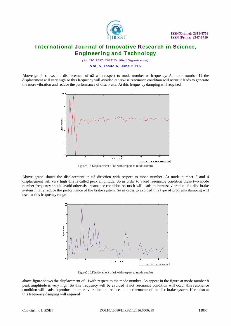
Figure5.15 Displacement of u3 with respect to mode number
Above graph shows the displacement in u3 direction with respect to mode number. At mode number 2 and 4 displacement will very high this is called peak amplitude. So in order to avoid resonance condition these two mode number frequency should avoid otherwise resonance condition occurs it will leads to increase vibration of a disc brake system finally reduce the performance of the brake system. So in order to avoided this type of problems damping will used at this frequency range
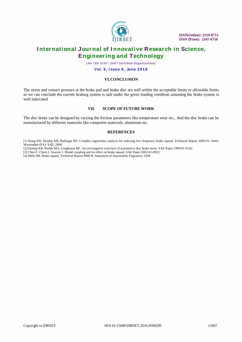
Figure5.16.Displacement of u1 with respect to mode number above figure shows the displacement of u1with respect to the mode number. As appear in the figure at mode number 8 peak amplitude is very high. So this frequency will be avoided if not resonance condition will occur this resonance condition will leads to produce the more vibration and reduces the performance of the disc brake system. Here also at this frequency damping will required
ISSN(Online): 2319-8753 ISSN (Print): 2347-6710
International Journal of Innovative Research in Science, Engineering and Technology
(An ISO 3297: 2007 Certified Organization)
Vol. 5, Issue 6, June 2016
Copyright to IJIRSET DOI:10.15680/IJIRSET.2016.0506299 11807
VI. CONCLUSION
The stress and contact pressure at the brake pad and brake disc are well within the acceptable limits or allowable limits so we can conclude the current braking system is safe under the given loading condition assuming the brake system is well lubricated
VII. SCOPE OF FUTURE WORK
The disc brake can be designed by varying the friction parameters like temperature wear etc., And the disc brake can be manufactured by different materials like composite materials, aluminum etc.
REFERENCES
[1] Kung SW, Dunlap KB, Ballinger RS. Complex eigenvalue analysis for reducing low frequency brake squeal. Technical Report 2000-01- 0444. Warrendale (PA): SAE; 2000. [2] Dunlap KB, Riehle MA, Longhouse RE. An investigative overview of automotive disc brake noise. SAE Paper 1999-01-0142. [3] Chen F, Chern J, Swayze J. Modal coupling and its effect on brake squeal. SAE Paper 2002-01-0922. [4] Mills HR. Brake squeal. Technical Report 9000 B. Institution of Automobile Engineers; 1938.