vol 28hi ft
TRANSCRIPT

CA9700623
TRI PP 94 104Dec 1994
The CHAOS Spectrometer for Pion Physics at TRIUMFGR. Smith*, P.A. Amaudruz*, J.T. Brack", L. Felawka*, A. Gorelov**,
R.A. Henderson*, D.F. Ottewell*, P. Vincent*, Y. Wu**, F. Bonuttib, P. Camerinib,N. Grionb, R. Ruib, J. Hoeyc, G. Hofmanc, M. Kermanic, D. Maasc, S. McFarlandc,
K. Raywood0, ME. Sevior0*, E.L. Mathied, R. Tacikd, P. Reevee, R.A. Ristinenf,E.F. Gibson", R. Meier*1', H.M. Staudenmaierh
*TRWMF, Vancouver, B.C., Canada V6T 2A3bInstituto Nazionale di Fisica Nucleate, Sezione di Trieste, and
Dipartimento di Fisica deU'Universitd di Trieste, 34127 Trieste, ItalycPhysics Dept., University of British Columbia, Vancouver, B.C., Canada V6T SA6
d University of Regina, Regina, Saskatchewan, Canada, S4S OA 2eUniversity of Victoria, Victoria, B.C., Canada, V8W 2Y2
* University of Colorado, Boulder, CO 80309, USA" California State University, Sacramento CA 95819, USA
hUniversitdt Karlsruhe, D-7500 Karlsruhe, Germany
Abstract
The Canadian high acceptance orbit spectrometer (CHAOS) is a unique magneticspectrometer system recently commissioned for studies of pion induced reactions atTRIUMF. It is based on a cylindrical dipole magnet producing vertical magnetic fieldsup to 1.6 T. The scattering target is located in the center of the magnet. Chargedparticle tracks produced by pion interactions there are identified using four concentriccylindrical wire chambers surrounding the target. Particle identification and trackmultiplicity are determined by cylindrical layers of scintillation counters and lead-glass Cerenkov counters, which also provide a first level trigger. A sophisticatedsecond level trigger system permits pion fluxes in excess of 5 MHz to be employed.The detector subtends 360° in the horizontal plane, and ±7° out of this plane for asolid angle coverage approximately 10% of 4T sr. The momentum resolution deliveredby the detector system is 1% (a).
(submitted to Nucl. Instrum. Methods)
•Present address: University of Colorado, Boulder, CO 80309, USA.'Present address: Simon Fraser University, Vancouver, B.C., Canada.'Present address: Institute of Atomic Energy, Beijing, China'Present address: University of Melbourne, Parkville, Vic, 3052 Australia.'Present address: TRIUMF, Vancouver, B.C. Canada V6T 2A3.
VOL 28Hi ft

1. Introduction
The Canadian high acceptance orbit spectrometer (CHAOS) is a magnetic spec-trometer with an angular acceptance of a full 360° in the horizontal plane, intendedfor studies of pion-induced reactions at TRIUMF. With this device, data are ac-quired simultaneously at every scattering angle within ±7° of the horizontal plane.The coincidence efficiency for reactions leading to two body final states is close tounity. The momentum resolution (dp/p) of CHAOS is ~ 1 % (a).
This unique facility can address a number of interesting 'second generation'experiments with pion beams. The complete angular acceptance makes it particularlywell suited for coincidence measurements. However, it is also meant to address singlesexperiments involving low cross sections. Each of these areas has proven difficult tostudy until now due to the exorbitant amount of beam time required for angle-by-angle measurements with conventional spectrometers.
The initial CHAOS physics program has focused on a systematic investigationof the H(n±,2n) reaction in a series of exclusive measurements. For incident n~,the H(TT~, 7r+n~)n and the H(TT~, n~7r°)p channels were measured simultaneously bydetecting the two charged particles in the final state in coincidence. Likewise forincident n+, the H(* + ,T + n+)n and the H(7r+,7r+ir0)p channels were measured si-multaneously. Pion bombarding energies of 220, 240, 260, 280, and 300 MeV werestudied and approximately 10,000 (n,2ir) events were recorded at each energy forthe channels with two charged pions in the final state. By measuring both reactionchannels for both incoming pion polarities from near threshold up to T, = 300 MeVover a broad angular range, it is possible to isolate the contributions from the vari-ous diagrams contributing to this process [1]. One goal of these measurements is toimprove the values for the S-wave isospin 0 and 2 irn scattering lengths a|j and a!,,which are predicted [2] within the framework of chiral perturbation theory to havevalues of 0.20 ± 0.01 and -0.042 ± 0.002, respectively. In addition, these data shouldpermit the extraction of inr scattering amplitudes as a function of energy.
Another of the physics goals in the CHAOS arena is the study of the Tr̂ p an-alyzing power Ay between 20 and 140 MeV, and between 45° and 180° . No datahave ever been published below 98 MeV. This information is crucial for phase shiftanalyses of TTN scattering. Near pion bombarding energies of 50 MeV there existsa strong S-P interference for backward angle n~p scattering, and strong Coulomb-nuclear interference at forward angles for jr+p scattering, which will be exploited inthese studies. The analyzing power, itself an interference of amplitudes, is especiallysensitive to the values of the smaller partial waves which are only poorly determinedfrom measurements of the differential cross section alone. The CHAOS Ay resultswill be used to distinguish between conflicting measurements of the differential crosssection at low energies. The poor agreement t>etween previous differential cross sec-tion measurements has made it virtually impossible to produce reliable nN phaseshifts. The CHAOS analyzing power data will also provide independent constraintson the value of the TTN E term [3], which is an explicit measure of chiral symmetrybreaking. The 7rN E term, in turn, can be related to the strange quark content of theproton. This experiment, as well as the (7r,27r) program, tests predictions of chiralperturbation theory [4], the low energy approximation of quantum chromodynamics(QCD).
2. Detector Overview
The experimental challenges posed by the ir^p and (ir,2n) measurements aresimilar in that they both require coincident particle detection with moderate (~1%)

momentum resolution, and they both are characterized by cross sections which dropbelow the 10 /ib/sr level in conjunction with background processes often several ordersof magnitude larger. Furthermore, systematic measurements covering a broad rangein angle and energy are needed. As a result a detector ensemble was designed [5j whichcould address these challenges. Other factors in the design include the following:The momentum resolution of the spectrometer should match that delivered by thebeamline. The TRIUMF beamlines deliver approximately 5% dp/p, which can bereduced by closing slits at the intermediate focus at the expense of pion flux. Inorder to achieve even the modest goal of 1% in momentum resolution, considerablecare must be devoted to a design which minimizes multiple scattering of the outgoingtracks. At the same time, however, full angular coverage was deemed an essentialfeature, and to facilitate acceptance calculations for the experiments, it was decidedto construct Belf-supporting wire chambers which contained no support posts orother features which would otherwise produce shadows in the acceptance. In order toremove potential ambiguities in track sorting and to provide some level of redundancy,at least 5 hits per track were desired (the final design provides up to 11 hits pertrack). The trigger system must permit the full intensity of the available beam tobe utilized (~5 MHz), which implies use of a sophisticated multi level hardwaretrigger system. The detector must accommodate polarized, cryogenic, and solidtargets. Good momentum resolution is required for all scattering angles. Goodparticle identification, in particular */p/e , is essential. Finally, a large cylindricaldipole magnet was available, the use of which resulted in a considerable savings inthe total cost of the project.
In order to achieve good momentum resolution for all scattering angles, thetraditional approach of orienting the magnetic field axis of the spectrometer longi-tudinal to the incident beam was abandoned in favor of an orientation in which themagnetic field axis is normal (vertical) to the nominal (horizontal) scattering plane.The scattering target is then situated in the center of the cylindrical dipole magnet,and surrounded by concentric, cylindrical wire chambers to record the spatial coordi-nates of charged particle tracks emanating from the target. Three wire chambers arelocated in a region of uniform magnetic field, where the trajectory of charged par-ticles is circular. A fourth chamber consisting of eight (cylindrical) planes is placedoutside the region of uniform magnetic field to improve the momentum resolutionof the device and to provide the extra redundancies needed for unambiguous tracksorting.
The GEANT Monte Carlo code was used to optimize the radii chosen for thewire chambers, to choose the number of chambers and wire planes required, to findthe spatial resolution required of the wire chambers, and to help determine whatmaterials were best suited for their construction. The most crucial parameter inthese studies was, of course, the overall momentum resolution. However, this wasconsidered in the context of the philosophy that the chambers would have to beself supporting with no support structures which would introduce angle-dependentcorrections to the spectrometer solid angle.
The facility which emerged from these design considerations [Cj is a chargedparticle magnetic spectrometer consisting of a dipole magnet with cylindrical poles95 cm in diameter and a 20 cm gap. The magnet is capable of producing verticalmagnetic fields in excess of 1.6 T. The scattering target is located in the center of themagnet between the poles. An open bore along the central (vertical) axis of the mag-net allows insertion of polarized and cryogenic targets. Four concentric cylindricalwire chambers view tracks emanating from the target over a full 3G0° range in thehorizontal plane, with a vertical acceptance of ±7° . The chambers are enclosed byconcentric rings of counter telescopes consisting of two layers of thin plastic scintillators plus Cerenkov detectors. The total solid angle of the facility is ~10% of \~K sr. A

sketch showing the general layout of CHAOS is shown in fig. 1. The four concentriccylindrical wire chambers are denoted WCl-4, with the innermost labelled WCl.The scintillator and Cerenkov blocks which enclose WC4 are shown together withtheir light guides and photomultiplier tubes (PMTs), and are denoted collectively asthe CHAOS fast trigger (CFT) counters. Further details of the detector are shownin fig. 2, which is a zoom of the central region with some sections of the detector cutaway for clarity.
3. The Magnet
One of the design features of CHAOS is the ability of the spectrometer to simul-taneously measure complete angular distributions and complete angular correlationsfor two body reactions. In order to meet this criterion, a cylindrical dipole magnetwith an exceptionally open geometry (ideally 360° angular acceptance) must be cho-sen. The magnet must be able to produce a vertical magnetic field which is uniformto ~ 1 % at least over the region between the inner three wire chambers. The magnetmust be physically large ( r~ l m) in order to accommodate wire chambers, and alsocapable of producing a large enough field for reasonable (~1%) momentum determi-nation. The /Bd l of the magnet should be in excess of 1 T-m. The vertical gapmust be large enough (>20 cm) to accommodate the wire chambers and calorimetry.There should be an open bore through the central axis of the magnet large enough(>12 cm 4>) to accommodate cryogenic and polarized targets. There should be noyoke or obstruction which might block the acceptance of the device inside a centralregion two meters in diameter. Finally, the return yoke outside this central regionmust allow for unobstructed passage of the incident and outgoing beam over a widerange of deflection angles.
An existing magnet at TRIUMF met most of these conditions to a reasonabledegree. It is a cylindrical dipole magnet (not superconducting) with an iron returnpath. It has a 12 cm diameter open bore. Although most conventional magnets havevertical yokes enclosing two sides of the magnet, the CHAOS magnet has narrowvertical return yokes located in each of the four corners of the (roughly square) topand bottom yokes. It has a 95 cm diameter pole. The magnet has been operated atfields in excess of 1.6 T.
The magnet was studied with a variety of computer codes (MAGDES, POIS-SON, TOSCA). Tapered iron pole tips were added to the existing magnet poles toreduce the gap in the central region to 20 cm. This permits higher maximum magnetic fields than otherwise possible, and also has the effect of flattening the fieldprofile in the region between the pole tips. By adding pole tips to the existing polesinstead of reducing the overall gap, the large gap between the coils was kept outsidethe central region, which greatly facilitates cable access and detector instrumenta-tion. In addition, ring shaped shims were added to the inner and outer diameters ofthe pole tips to tailor the field in the central region. Finally, the amount of steel inthe upper and lower yokes as well as in the four corner return yokes was doubled toreduce saturation. The four corner yokes were moved to greater radii and reconfig-ured in order to maximize the open space between the corner yokes and strengthenthe support provided between the upper and lower yokes.
Fig. 3 shows the final magnet configuration. The field is uniform to better than1% between about 5 and 35 cm. The magnet is 1066 mm high and 2235 mm wide,outside dimensions. The B I curve of the magnet is linear up to about 0.9 T (200amps) and is already entering saturation at 1.4 T (400 amps).
Extensive two dimensional magnetic field maps were measured at four elevationsand four magnetic field settings using a three dimensional Hall probe. The Hall probe

readings were cross checked with an NMR probe in the flat field region. One quadrantof the magnet was mapped in this procedure out to a radius of 1.8 m. No appreciableasymmetry was found in the measured field distribution in the region where the wirechambers are located. These maps are used in the momentum reconstruction routinesemployed in the analysis of CHAOS events by interpolating the position and centralfield strength between the points measured in these field maps. An NMR probesituated on the face of the lower pole tip at an approximate radius of 22 cm is usedfor normalization.
Since the incident pion beam deflects as it traverses the spectrometer, the mag-net must be translated perpendicular to the nominal beamline in order to insure thatthe beam strikes the target. In addition, it is convenient to rotate the spectrom-eter about its central axis to facilitate the beam entry and exit locations relativeto the four corner return yokes. As a result, a stand was built which employs ahydraulic cylinder and four Hillman roller bearing assemblies which ride on a pairof 3.66 m long rails consisting of 2.5 cm x 10.2 cm flat bar grouted (2.5 cm high)onto the floor of the experimental area. This system can translate the entire ~55ton spectrometer up to 1.8 m from the beamline. In addition a cylindrical cranebearing is also installed which allows the entire spectrometer to be rotated by anAC motor. Shaft encoders are employed in conjunction with digital readout systemsdesigned and built at TRIUMF to read out the translation of the spectrometer towithin 0.013 mm and the angle of rotation to approximately 0.0015° . Typical valuesof the required translation and resulting rotation of the incoming beam at the centraltarget for an incident beam momentum of 300 MeV/c and spectrometer field of LOTare 166.8 mm and 31.8° .
A platform is attached to the magnet on three sides flush with the top surfaceof the magnet, about 2.5 m off the ground. It provides access to both sides of thesix electronics racks situated on top of the magnet, which contain virtually all of thereadout electronics for the detector. Personnel access to the electronics platform ispossible while the magnet is in the experimental area receiving beam. In order togain access to the wire chambers for installation, cabling, and repair work, the upperhalf of the magnet must be removed. Access to the wire chambers is then providedby means of a cart rolling on a horizontal ladder which can be attached to the magnetapproximately 20 cm above the top of the wire chambers.
4. Proportional Chamber* WCl and WC2
Factors in the design of the two innermost CHAOS wire chambers include thefollowing: Since these chambers are located near the focus of the incident beam andhave small diameters, the rate per wire can be high (roughly 1 MHz per wire for a2 mm anode pitch). In order to facilitate vertex reconstruction and scattering angledetermination, it was deemed necessary to be able to track the incoming pion beamat rates up to 5 MHz with these two chambers, as well as any outgoing tracks. SinceWCl and WC2 are situated in the homogeneous region of the spectrometer magneticfield, the spatial coordinate each delivers can be used in conjunction with the knownincoming beam momentum to fully reconstruct the trajectory of the incoming beamonto the target. Vertical tracking (in the direction parallel to the spectrometer field)was also required of these chambers for the same reasons. Monte Carlo calculationsindicated that the innermost chamber should be situated at as small a radius aspossible and have an angular resolution better than 1/2° . Practical considerationswere that some volume had to be left free to accommodate the central target andthat it is difficult to construct a cylindrical chamber with an anode pitch less thanabout 1 mm. The geometry of WCl was therefore fixed by the dual requirements of1 mm anode pitch and 1/2° angular resolution. Monte Carlo calculations indicatedWC3 was best situated at the outer edge of the uniform field distribution, and that

the optimal radius of WC2 was about halfway between WC1 and WC3. With thisradial constraint as well as the 1/2° angular resolution required, a 2 mm anode pitchwas chosen for.WC2.
The two innermost CHAOS wire chambers are proportional chambers locatedat radii of 114.59 (WCl) and 229.18 mm (WC2). Each has a half-gap (anode wire tocathode plane distance) of 2 mm, and contains a total of 720 gold-plated tungstenanode wires 12 fxm in diameter. The wires cover the entire 360° angular acceptanceof the spectrometer with an active height of 70 mm.
Each anode in each chamber is equipped with a preamplifier mounted directlyon the chamber. The bipolar Fujitsu MB43458PF quad preamplifier chip was cho-sen due to its excellent performance and compact size. The 16-channel preamplifierboards also capacitatively decouple the anode high voltage at the input of the pream-plifier. Coaxial cables (Alpha 9374) 3 m in length deliver the anode pulses to LeCroy2735PC amplifier discriminator cards powered in specially constructed crates, each ofwhich contains up to 21 cards. Two such crates are attached to each of the four cornerreturn yokes of the magnet. The ECL outputs of the amplifier/discriminator channelsare then delivered on 17 channel flat twisted pair cables (Belden 9V28034) to LeCroy2731A delay/latch modules which form part of the LeCroy PCOS III readout system.This, as well as all other readout systems associated with the spectrometer, is locatedon top of the magnet so that the entire spectrometer can be moved from one experi-mental area to another without disconnecting a single wire upstream of the readoutsystems. PCOS III was chosen because it provides zero-suppression, programmabledelay for each channel relative to the common strobe, and a programmable thresholdfor each 2735PC card. The system is operated in 'cluster mode', which delivers thecentroid (and width) of a cluster of up to 16 adjacent wires including a 'half-wire'bit if the cluster width is even. The spectrometer magnet deflects the tracks passingthrough WCl and WC2 sufficiently that several adjacent anodes usually fire for eachtrack, effectively improving the angular resolution of these two chambers by a factorof two, to 1/4° , in the cluster mode of operation. In addition, the LeCroy 2738PCOS III controllers provide ECL output which is convenient input to the CHAOSsecond level trigger.
Each of the first two chambers is also equipped with cathode strips inclined 30°with respect to the anode wires, on the outer cathode surface of each chamber. Thepitch of these strips is 2 mm (WCl) and 4 mm (WC2). Each of the 360 strips in eachchamber is preamplified at the chamber and delivered to 16 channel inverter/amplifiercards via coaxial cables 3 m long. The inverter/amplifier cards were designed andbuilt at TRIUMF and are based on SL560 chips. One crate capable of housing 21 suchcards is located on each of the four corner return yokes of the spectrometer magnet.The analog output of these cards is delayed 210 ns by means of RG174/U coaxialcables 40 m long. The delay cables are jacketed in bundles of 16, spooled in pairsand hung on rods fixed to the spectrometer magnet. The delayed cathode signalsare digitized in LeCroy 1882F FASTBUS analog to digital converters (ADCs) whichare gated by a signal 100 ns wide. The delay is necessary to allow the gate signal tobe formed, which is the result of the first level trigger decision based on the numberof tracks found in the scintillation counter arrays. The FASTBUS crate is read outwith a LeCroy 1821 segment manager/interface which is programmed to performpedestal subtraction, threshold comparison, and zero suppression. Typically severaladjacent cathode strips which are associated with a given cluster of struck anodessurvive this procedure. The charge-weigh ted centroid of the strips is determined,and together with the anode information, the vertical coordinate of the trajectorycan be determined in both WCl and WC2for tracks separated by more than 30°. Thevertical resolution delivered by WCl (WC2) is 2.4 mm (0.7 mm), as determined in aniterative calibration procedure with non scattered tracks, and including information

from WC4, discussed below.The two proportional chambers are of identical construction except for the
different radii, anode and cathode pitches. A side section view of WCl and WC2,including the other detector elements as well, is shown in fig. 4. Each chamber iscomposed of two independent cylinders. Each cylinder consists of an upper and alower GlO ring held 70 mm apart by a 1 mm-thick cylinder of rohacell. Ronacell waschosen for its exceptional strength and small density of 50 mg/cm3, which minimizesmultiple scattering. The main drawback of this material is the fact that it contractsas the humidity is lowered, as happens when it is in contact with chamber gas. Thiseffect was kept under control by baking 4 mm-thick sheets of rohacell at 160° C priorto machining to the required size and thickness, as well as gluing stretched foils to theinner and outer surfaces of the rohacell cylinders. The inner cylinder has a 12 /iin-thick kapton foil glued to its inner surface, and a 25 /im thick foil of aluminizedmylar glued to its outer surface. The latter serves as the inner cathode plane for thechamber. This plane is in addition covered with a thin layer of graphite to retardpolymerization. The anode wires are soldered under 10 g of tension directly to circuitboard strips glued to the GlO rings of the inner cylinder, 2 mm from the cathode foil.The cathode strips were photochemically etched on an electro-coated copper/nickel(ECN) foil consisting of 25 /im kapton, 1200 A copper, and 300 A nickel which wasglued to the inner surface of the outer cylinder. Contact to the strips was achievedusing gold plated spring clips which were in mechanical contact with the strips onone end and soldered to a circuit board on the other. A 12 fim kapton foil was gluedto the outer surface of the outer cylinder.
In addition, 25 fxm aluminized mylar foils were glued to the GlO rings at ±8 nunfrom the anode radius in order to isolate the chainber anodes better from outsideelectromagnetic interference, as well as to provide a nitrogen flushing volume toisolate the chamber gas better from the environment between chambers. Until nowthat environment has consisted of air. However, the GlO rings were designed topermit foils to be stretched between the rings of adjacent chambers to form a helium
The two independent cylinders of each chamber are joined together by meansof natural rubber tubes inserted in the 2.8 mm gap between the inner and outer GlOrings. One such tube is positioned between the top pair of rings, another between thelower pair. The tube is easily positioned by collapsing it into a flat ribbon using asyringe to deflate the tube. Likewise the tube is reinflated with a syringe, forming agas tight seal and freezing the relative position of the two cylinders. Three 0.7 mmdiameter pins are used to index the two cylinders so that their relative positions canbe reproduced after the cylinders are separated during a repair procedure. Repairsare greatly facilitated by having the anode wires on the inner cylinder and the cathodestrips on the outer cylinder since once the cylinders are separated, access to eitherthe anodes or cathode strips is unrestricted. Ring stands were built which employan eccentric system which permits each chamber to be independently rotated andcentered with respect to the center of the magnet.
The operating (anode) voltages of WCl and WC2 are +2500 volts and +2100volts, respectively. At these voltages, WCl (WC2) has an anode efficiency of 96%(92%) for minimum ionizing pions. This positive high voltage is daisy chained to theanodes of each chamber via small printed circuit boards attached to the bottom ofthe chambers.
WCl and WC2 operate with a mixture of CF4 and isobutane gas in an 80.20ratio. The gas volumes of WCl and WC2 are 0.2 and 0.4 liters, respectively, and theflow rate of gas through each chamber is approximately 100 cm3/ininute. The CF4 isrecirculated in a closed system built by the TRIUMF detector group [7]. Isobutanedetectors are installed in the experimental area as well as in the detector itself toreveal leaks. A further safety measure is a blower located below the magnet which

establishes an air flow from the center of the spectrometer to the outside world,cooling the electronics in the central region and removing any potential isobutanegas pocket at the same time.
Clean spectra from these chambers were acquired only after considerable workwas done to eliminate initial noise problems. The most significant improvement wasthe addition of a copper ground skirt which was soldered directly to the groundplane of the circuit boards to which the anodes were soldered, on the bottom ofthe chambers. Furthermore, oscillations develop in the 2735 amplifier/discriminatorcards unless all inputs and outputs are properly terminated. Discriminator thresholdson the 2735PC cards are set at the maximum value which can be obtained from thePCOS system. Further details on these two chambers are described elsewhere [8].
5. The High Field Drift Chamber WC3
Monte Carlo calculations indicated that the spatial resolution required in WC3had to be < 200 /iin (a) in the scattering plane, and that the radius of this chamberhad to be near the outer edge of the flat field region in order to meet the design goal of1% momentum resolution for the spectrometer. A third chamber inside the flat fieldregion was also desired in order to have an analytic solution for the track momenta.A fast proportional chamber would have been ideal, but even with a 1 mm pitch, itwould only deliver an r.m.s spatial resolution of 300 urn. Furthermore, instrumentinga 1 mm pitch chamber at this radius with readout electronics would be prohibitivelyexpensive. In order to keep the cost of WC3 comparable to that associated with eachof the other chambers in the spectrometer, and to obtain spatial resolution below200 /iin, it was therefore decided to build a drift chamber.
This option comes with its own set of problems. The design calculations calledfor a fourth chamber and so multiple scattering in the third chamber had to beminimized. This could only be accomplished in a single (cylindrical) plane driftchamber. Furthermore, the angle at which tracks pass through the chamber can varyby about 90° (±45°), depending on the spectrometer field and track momentum andpolarity. Since the spectrometer field can be as large as 1.6 T, the Lorentz angleassociated with electrons drifting towards the anodes in WC3 can exceed 90° .
There is a left/right (L/R) ambiguity associated with whether the electronsdrifted to the anode from the left or from the right of the anode. A measure ofthe drift time alone does nothing to resolve this ambiguity. The effects of largemagnetic fields and varying incident track angle combine to such a degree in CHAOSthat traditional solutions to the L/R ambiguity no longer work. Usually, the chargeinduced on cathode wires adjacent to the anode or on cathode strips located to theleft and right of the anode is used to resolve the ambiguity. Since in the CHAOSenvironment (high B field, low E field, and varying incident track angle) the anodeavalanche can occur in front of or behind the anode instead of to the left or to theright, these techniques fail. A simple yet novel technique was therefore applied byinstrumenting both the inner and outer (cylindrical) cathode planes with cathodestrips. Each drift cell contains four cathode strips, two on the inner plane, two onthe outer plane, centered on the anode. Instead of examining the difference in chargeinduced on adjacent strips, the diagonal combination is taken, which permits theL/R ambiguity to be resolved for all track angles and magnetic fields up to 1.6T.This technique was studied in detail with five prototype chambers, and the resultsare published m ref. [9].
The VVC3 anodes are located at a radius of 343.78 mm, just inside the taperedpole tips of the spectrometer magnet. The chamber consists of alternating anodeand cathode wires in an approximately rectangular cell geometry. The anode pitch is15 mm (2.5° ), and the half gap of the chamber is 3.75 mm. Therefore the maximum
8

drift distance is nominally 7.5 mm (approximately 150 ns maximum drift time at zeromagnetic field). As mentioned above, each of the 144 cells in the chamber is equippedwith four cathode readout strips. In addition, two smaller strips are implementedin the corners of each cell to improve the electric field in those regions. The cellgeometry is shown in fig. 5.
The anode signals are capacitatively decoupled from the high voltage and pream-plified at the chamber, and brought out of the detector on ten foot coaxial cables toLeCroy 2735DC amplifier discriminator cards positioned in crates on the four cornersof the magnet, as with WC1 and WC2. The 2735DC output is carried on ECL ribboncables to the PCOS III system as with the two inner chambers. However, the WC3ECL cables are not terminated at the 2731A PCOS input, but continue to the inputof LeCroy 4291 time-to-digital converters (TDCs), so that each anode of WC3 isread out by the PCOS III system as well as the 4290 TDC system. The WC3 PCOSreadout is used in conjunction with that from WCl and WC2 to form the input tothe second level trigger. The 4290 readout is used to digitize the drift times andtake the WC3 spatial resolution from the 7.5 mm available in the PCOS readout to200 /im.
The four cathode readout strips in each cell used to resolve the L/R ambiguityare preamplified at the chamber, and follow the same route as the cathode stripsof WCl and WC2, described earlier. In total there are 576 channels of FASTBUSADCs associated with the cathode strips of WC3. Since these strips are vertical andare used for resolving the L7R ambiguity, no vertical information is available fromWC3. The width of the ADC gate used to digitize the WC3 cathode signals is largerthan that used for WCl and WC3 to account for the longer drift time in WC3: agate 500 ns wide is used for WC3 (and WC4).
The >150 ns drift time prevents this chamber from operating safely in thenarrow angular regions where the incident pion beam passes through the chamber.Therefore, the incoming and outgoing beam regions in WC3 are deadened by turningoff the anode voltage for the affected cells. A special high voltage patch panel wasbuilt which permits grouping of four WC3 cells either to ground or to high voltage.Typically one such group of four cells is deadened in the incoming beam region, andtwo groups are deadened in the outgoing region.
The construction of this chamber is similar to that of WCl and WC2 in that twoconcentric 1 mm-thick rohacell cylinders separated by 7.5 mm are used to supportthe wire tension. In this case, however, the G10 support rings are drilled to acceptcrimp pins through which the anode and cathode wires are strung and crimped. Thesame technique used in WCl and WC2 is employed to join the WC3 cylinders andprovide a gas tight seal. The anode wires are 50 (im diameter gold-plated tungstenPensioned to 100 g. The cathode wires are 100 ftm in diameter tensioned to 150 g.The anode and cathode wires are 90 mm in length. Each of the four vertical cathodereadout strips in a given cell is 4 mm wide, and the field shaping cathode stripsare 3 mm wide. The foils applied to the rohacell cylinders of WC3 are identical inthickness and composition to those of WCl and WC2, except the outer surface of theinner WC3 cylinder consists of an etched ECN foil instead of plain aluminized mylar.Gold-plated spring clips were again used to achieve reliable electrical contact betweenthe strips ana the cylindrical circuit board to which the preamplifiers connect. Aswith the inner two chambers, additional 25 /im aluminized mylar foils (±9.8 mmfrom the anodes) are employed to provide a flushing volume and improved electricalisolation. The chamber is seated in an eccentric ring stand of design similar to thatof the inner two chambers.
The high voltage requirements of WC3 are +2.250 kV on the anodes, —600 voltson the cathode wires, and —300 volts on the field-shaping cathode strips. The ef-ficiency of the chamber at this voltage is typically 94%. The four cathode readoutstrips in each drift cell receive no high voltage. Both WC3 and WC4 use a drift gas

mixture of argon-ethane (50:50) with an additional 0.4% ethanol as a quenching gas.The flow rates are similar to the first two chambers (100 cm3/minute), however thevolumes are quite different: WC3 has a volume of 2 liters, and VVC4 has a volume of10 liters.
The relatively low and spatially-varying electric field produces a large Lorentzangle and hence electron trajectories are highly curved. Coordinate reconstructionfrom the drift time is complicated by the dependence on the track angle of incidence,the drift time, and magnetic field strength. The chamber is calibrated with an itera-tive technique which uses the actual data acquired in a given CHAOS experiment. Atwo-dimensional lookup table of drift time and track angle contains best estimateddrift distances. A large number of tracks is analyzed and residuals are collected.The residuals are defined as the differences between the coordinates obtained fromthe WC3 lookup table, and those obtained from a least squares fit using coordinateinformation from all four wire chambers. These residuals, averaged for each TDCbin and each 2° track angle bin, are used to improve the look-up table used in thenext iteration. This process is repeated until satisfactory convergence is achieved.At present, the same drift time to distance relation is used for all cells. Furthermore,the anodes are assumed to lie in a cylinder of radius 343.78 mm. The offsets androtation of this cylinder in the spectrometer plane relative to the other chambers arealso determined by a fitting procedure.
0. The Vector Chamber WC4
Although in principle the inner three chambers discussed above are sufficient todetermine the momenta of charged particle tracks in CHAOS to a few percent, thedesign Monte Carlo calculations indicated a fourth chamber was necessary to bringthe momentum resolution of the spectrometer to the 1% level. A fourth chamber wasalso deemed necessary to resolve potential track sorting ambiguities. The calculationsindicated that the chamber should be situated at a radius near 650 mm (where themagnetic field of the spectrometer has fallen to 10 or 20% of its central value) andthat the spatial resolution required was stringent enough that a drift chamber wasnecessary. On the other hand, since this chamber is positioned at the end of thecharged particle track, multiple scattering was no longer of much concern and acompletely different design could be used which incorporates several (cylindrical)anode planes within one chamber.
A trapezoidal cell geometry was chosen (see fig. 6), similar to that used inref. [10] but incorporating several improvements over that design. Each of the 100cells in WC4 is 3.6° wide and consists of 14 anodes staggered alternately ±250 punperpendicular to a radial line bisecting the cell. The anodes of WC4 therefore define14 concentric cylindrical planes, or layers. The radius of the first layer is 612.50 mmand successive layers are separated by 5 mm. The drift times to the middle eightlayers are digitized to provide the vector associated with the track passing throughthe cell. Layers 2 and 13 consist of resistive wires which are used to determine thevertical coordinate of the track at those anode radii by the method of charge division.Layers 1, 3, 12, and 14 consist of guard wires used to tailor the electric field in thecell. In this region of low spectrometer field, a straight line is used to approximateparticle tracks over the 4 cm active depth of WC4.
Rather than use cathode wires to define the boundaries between adjacent cells,which dramatically increases the wire tension to be supported, cathode strips wereused in a novel scheme which actually helps support the chamber instead. Thisscheme was implemented using C-shaped frames of 1.6 mm-thick G10. Rohacellsheets 2 mm thick were glued into the opening of the G10 C-frames. 25 /im-thickECN foils with the cathode strip pattern photochemically etched on one side wereglued to each face of the G10/rohacell assembly. While the glue was still wet, the
10

entire assembly was placed in a steel mold heated to 160° and compressed to athickness of 1.6 mm in a 1 ton hydraulic press. The cathode strip pattern on eachfoil consists of nine 7.4 mm wide strips separated by 1.0 mm. Since the drift cellsare trapezoidal, the cathode voltage is dropped 55 volts across each strip by meansof a chain of 3.02 MQ resistors in order to keep the electric field in the cell uniformand perpendicular to the row of anode wires. A larger resistance drops the voltageon the last (innermost) strip to ground. The circuit pattern for the resistor chain isetched on each side of the G10 frame and connected to the cathode strip pattern viagold-plated spring clips.
The top and bottom of the chamber consist of 8.5 mm-thick ultem plates whichwere drilled to an accuracy of 20 /im with the anode wire pattern. The holes weredrilled 1.00 mm in diameter to accept crimp pins through which the anode wireswere strung and crimped. An upper and lower ultem plate were held 231 mm apartby means of the G10 C-frames with the cathode strip patterns (ribs), as well asby a 250 /iin-thick backwall of G10 glued to the outer edge of both ultem plates.This outer G10 window was copper laminated on the inside surface and nickel platedto provide an outer cathode plane common to all cells of the chamber. The spineof the G10 C-frames was glued to this outer window, and the chamber was furtherstrengthened by gluing 1.6 mm thick G10 spines to the outer surface of the outer G10window directly behind each C-frame spine, effectively continuing the C- frame spinethrough the outer window another 15 mm. The C-frames were further attached tothe ultem plates by means of grooves in the top plate into which they were glued, aswell as slots in the bottom plate to which they were also glued. The resistor chaincircuit pattern on each C-frame protrudes through this slot beneath the lower ultemplate. With the outer window and C-frames glued in place, the chamber was strungwith the anode wires. The inner window was fabricated with 1 mm thick rohacellcontaining a 12 /im-thick kapton foil on the outside and a 25 /im-thick aluminizedmylar foil on the inside. The aluminized mylar formed the inner cathode surfacecommon to all drift cells of the chamber.
Due to the large diameter of the chamber it was built in eight sections: fourof these were 36° wide and four were 54° wide. All eight sections were mountedtogether on a common ring rigidly attached to the magnet.
The eight drift anodes in each cell consist of 20 /jm diameter gold plated tungsten tensioned to 50 g. The two resistive wires per cell are 20 ^m diameter Stablohm 800 tensioned to 10 g. The resistance of these wires is approximately 1 kilover the 25 cm length of the wire. The guard wires are 150 ftm and 75 pun gold-platedtungsten. The operating bias of WC4 is —5.2 kV applied to the cathode strips, aswell as —2.3 kV applied to the inner and outer cathode windows. It shares the samegas system as WC3.
The drift anode signals are preamplified at the chamber and followed a similarpath as described for the anodes of the other chambers, through LeCroy 2735DCamplifier/discriminators to the 4290 TDC system. The resistive wires were treateddifferently from the cathodes of the other chambers, however. Short coaxial cableswere used to bring the pulse from the bottom of the resistive anode wires to pream-plifiers mounted on top of the chamber which also preamplify the signals from the topof the resistive wires. Two channels of the same quad Fujitsu MU43458PF pream-plifier chip were used for a given resistive wire. The pulses were then delivered on3 in-long alpha 9374 coaxial cables to cards located in crates situated on each of thefour coiner yokes of the magnet which consist simply of passive adapters for differentconnector types. The signals from these cards then follow the same route throughthe same type and length of delay cables as used for the chamber cathodes and aredelivered to the FASTDUS ADC system. A 500 ns wide ADC gate is used.
Since the maximum drift time to the anodes of WC4 is ~450 us, the cells illumi-nated by the incident beam were deadened in a procedure similar to that describedfor WC3. The cathode strips were grounded in groups of two so that three cells
11
at a time were deadened in this procedure. Typically one group of three cells wasdeadened where the beam enters the spectrometer, and two such groups where thebeam exits.
The L/R ambiguity in WC4 is solved by making use of the ±250 /*m staggeringof the anode wires. The drift times to those anodes staggered towards a given trackare generally shorter than to those staggered away from the track. This techniqueworks well for resolving the L/R ambiguity, however the absence of cathodes betweeneach anode leads to problems. The avalanches on the wires closest to a given trackoccur earlier and produce large induced pulses on the neighboring wires. The pulseobserved on the wires staggered away from the track is then the sum of the avalancheon those wires plus the induced pulse from the neighboring wires. This problemwas corrected to a large degree by means of a second order resistor cancellationnetwork [10] implemented on the input of the preamplifier circuit boards of each cell.
The spatial resolution provided by the drift anodes of WC4 is easily measuredby constructing the residuals of the wires, defined for anode wire i as
U-1 - t>, 2 < i < 7 (1)
A typical residual histogram is shown in fig. 7. Two peaks separated by 1 mm (twicethe stagger) appear, which are associated with whether the track passed to the leftor right of the anode plane. The small difference in the width of each peak is a resultof an imperfect cancellation network, as described above. The figure shows that theaverage spatial resolution for a single wire is 120 fi(cr). The vertical spatial resolutionprovided by the resistive anode wires is 2.3 mm (<r), better than 1% of the length ofthe wire.
The homogeneous electric field (~ 2 kV/cm, < 100 V/cm variation) and themuch lower magnetic field at the WC4 radius allow a straightforward drift time todistance relationship. We have parametrized the perpendicular distance from theanode wire plane to the track by:
d = v(TDC - to)[cov(0t) + tan(<f>) x HiniOi)] + | x tasx2(<f>)o
where the drift velocity v and the Lorentz angle 0/ are adjustable parameters. <f> is thetrack angle of incidence, and to is the TDC onset. The first two terms are geometricalcorrections to drift trajectories of angled tracks. The last term is a correction forthe curved field lines near the anode wire [10]. Iterations on a large set of tracks arecarried out to establish optimum values for v and 0j for each setting of the magneticfield, v and $i are presumed common to all cells of WC4. The WC4 anode positionsart1 assumed to be perfectly cylindrical. As with WC3, the center and rotation of theWC4 cylinder are optimized with respect to the other chambers.
7. The CHAOS Fast Trigger Counters and First Level Trigger
The readout systems for the wire chambers require gates and strobes. In par-ticular, the 1C9C analog signals digitized by the FASTBUS ADC system are delayed210 us, so an ADC gate must be issued within that time interval for those eventsdeemed interesting. An appropriate condition on which to base this decision is thetrvt'iit multiplicity, which corresponds to the number of charged particle tracks pro-duced in an interaction of the beam with the target falling within the detector ac-ceptance.
The CHAOS fast trigger (CFT) counters were designed for this purpose, aswell as to provide particle identification (7r, e, p, d) of all detected tracks. The
12

counters are assembled in 20 adjacent blocks each 18° wide, situated just outside theWC4 radius in a contiguous cylindrical array concentric with the chambers. Eachblock consists of three elements. The innermost element (AEj) is a 3 mm-thickNE110 scintillation counter 178 mm (±7°) high. It is a cylindrical segment 18° wide(226 mm) with a radius at its inner surface of 720 mm. The AEi counters definethe 1.54 steradian total geometric solid angle of the detector. Just behind thesecounters is a pair of adjacent 9° (115 mm)-wide NE110 scintillators 12 mm thickand 180 mm high denoted AE2L and AE2R. The third and outermost element ofthe detector is located just outside the AE2 counters and consists of SF5 (radiationlength 2.55 cm, n=1.70) used as a Cerenkov detector. 125 mm-thick blocks of SF5are joined together to form a trapezoid with a frontal area of 237x223 mm2 and reardimensions of 275x253 mm2. Three lucite light guides collect light from the rear ofeach SF5 block. Each AEt is viewed by a Hamamatsu R329-02 photomultiplier tube(PMT), as are the three lucite light guides in each SF5 block. The AE2L and AE2Rcounters are each viewed by an EMI 9815B PMT. All PMTs are shielded with ironand /imetal, and the lucite light guides for each counter place the PMTs well outsidethe spectrometer magnet where the fringe fields are within acceptable limits.
A gain monitoring system for the 120 PMTs comprising the CFT blocks is basedon a xenon lamp which is flashed at regular intervals. The light from each flash isdelivered to the light guides of each counter via optical fibers, and the light outputis calibrated using a reference PMT and scintillator in contact with a 207Bi source.This system is described in detail in ref. [11]. The PMT high voltage is supplied bya bank of eight Power Designs 1570 3 kV, 40 mA high voltage power supplies feedinga (PC) computer-controlled CAEN SY170 high voltage distribution system.
Only 18 of the 20 CFT blocks are in use at any given time. One block is removedwhere the beam enters the spectrometer, another is removed where the beam exitsthe spectrometer. Eight of the CFT blocks are situated just inside the four returnyokes in the corners of the magnet. These blocks are fixed in place. The other 12blocks are mounted on carts that can be rolled in and out of the spectrometer onbearings to facilitate block removal for beam entry and exit.
Ancillary counters include a four element scintillation counter hodoscope (Si)consisting of 3.2 mm-thick horizontal strips 10 cm wide and each 7.5 cm high. Thiscounter is situated just downstream of the last quadrupole magnet in the pion beam-line. A second scintillation counter hodoscope (Sj) is situated just upstream of WC4where the beam enters the spectrometer. It consists of four vertical strips 1.6 mmthick and 10 cm high. The middle two strips are each 8 mm wide and the outertwo strips are 12 mm wide. A pair of veto counters (V) similar in size to the AE2counters but only 3.2 mm thick is situated where the beam exits the spectrometerin place of the CFT block that would otherwise occupy that position. Dependingon the experiment, a first level trigger strobe is formed from the coincidence S| x V,Sj x V, or S, x Sj x V.
The output of each CFT PMT is delivered on coaxial cables to a bank of LeCroy4413/200 high impedance-bridged input discriminators. The (bridged) analog outputis delayed 120 ns with RG174/U coaxial cables and the pulse heights are digitizedwith LeCroy 4300B FERA ADCs. The ECL output of the discriminator is delayedand fanned out in LeCroy 4518 modules. One of the three 4518 outputs providedfor each PMT signal is scaled in CAEN C257 CAMAC sealers. Another output isfed to programmable logic units (LeCroy 4508 PLU). The third 4518 output of theAE, and AE2 scintillators is delivered to Phillips 7186H TDCs. The 4508 PLUs areprogrammed with the coincidence requirements for each CFT block desired in a givenexperiment. Usually this consists of a coincidence between AEj(i) and the logicalOR of AE2L(i) or AE2R(i) for CFT block i. If the requested coincidence pattern in
13

a given block is present when the first level trigger strobe is applied to the PLUs, anoutput for that block is fed to an input of a pair of LeCroy 4532 majority logic units(MALUs) which count the number of such coincidences among all CFT blocks. TheMALUs may be programmed to provide an output when 1 or more such coincidencesare present, or when >2 are present, and so on, thus establishing the desired eventmultiplicity. The MALU output is the first level trigger. It passes through a finalcoincidence to check whether the data acquisition computer is busy or not, and thenis fanned out to provide all the gates and strobes required by the various electronicreadout systems, as well as to start the second level trigger decision-making process.The propagation time through the first level trigger is only 100 ns, and it has beensuccessfully tested at rates up to 35 MHz. The CHAOS CFT counters and first leveltrigger are explained in detail in ref. [12].
8. Second Level Trigger
Since high incident beam rates and large physical backgrounds are typical of theexperiments planned with CHAOS, the rate of first level triggers can easily exceedthe capability of the data acquisition computer. Restrictions on the events passed tothe data acquisition computer beyond those established by the first level trigger aretherefore required. This is accomplished by the CHAOS second level trigger (SLT), aprogrammable hardware trigger system based in CAMAC ECL modules which filtersevents passed by the first level trigger. The conditions which the SLT requires aredeveloped in stages. The main stage requires the existence of a track defined by hitsin WC1, WC2, and WC3, a track momentum within a specified range, a specific trackpolarity, an interaction vertex (actually a distance of closest approach of a track tothe origin) within a specific range, and a specific range of incoming trajectories (usedto reject muons arising from pion decay along the pion channel which contaminatethe incident beam). Two optional, additional stages are also available. One is a p-0stage which requires a specific correlation between track momentum and scatteringangle. Another is useful for coincidence experiments, specifically (TT,2TT) reactions,and requires that two tracks pass the main stage and further that the sum of themomenta of these two tracks falls within a specified range.
The SLT bases its decisions on the wire numbers associated with hits in theinner three wire chambers delivered by the ECL output of the PCOS III electronics.All hits recorded by each of WC1, 2, and 3 for a given event are stored in LeCroy2375 data stacks and all possible combinations of these hits are tried until a successfulcombination is found which satisfies the preprogrammed conditions. If no successfulcombination is found, or if there is not at least one hit in each of WCl, 2, and 3 tobegin with, the SLT issues a fast clear to all the electronic readout systems and theevent is rejected prior to ever being acknowledged by the data acquisition computer.
Use is made of the rotational symmetry of CHAOS to reduce the word sizerequired to represent each hit combination.
All trial tracks are rotated such that the WC2 hit is at zero degrees, effectivelyeliminating WC2 from the subsequent calculations. The rotation is accomplishedusing LeCroy 2378 arithmetic logic units. The heart of the trigger, however, is inthe extensive use of memory lookup units (MLUs) which are preprogrammed withthe result of the trigger criteria for every possible input pattern. Several LeCroy16-bit 2372s are employed as well as more powerful 21-bit MLUs designed and builtat TRIUMF for the CHAOS SLT.
The time required for a decision from the SLT depends on the number of hitsrecorded by each of the three inner wire chambers, and on how soon a successfulcombination of hits is found. The typical time required for an event to be tested onall the conditions listed above is 2-4 /is. Typical event rate reduction factors provided
14

by the SLT are between 10 and 1000. The SLT is described in detail in ref. [13,14].
0. Acquisition System
The readout electronics for the various elements of the detector consist of or-dinary CAMAC modules, FASTBUS, and special systems (PCOS III and the 4290system). CHAOS was commissioned using a slow but well-understood data acquisi-tion system based on CAMAC and running in a J l l Starburst microprocessor. Afterthe detector was commissioned, the acquisition system was changed to a VME systembased on a preliminary version of the CEBAF online data acquisition system CODA.All readout systems which deliver ECL output are funneled into LeCroy VME 1190dual port memory modules which store all the zero-suppressed data from that readoutsystem for a given event. VME 1190 modules receive data from the PCOS III, FERA,and FASTBUS systems. The FASTBUS ECL data are formed by implementing aLeCroy 1821/ECL 'personality' card on the auxiliary backplane of the FASTBUScrate behind the 1821 segment manager/interface. Unfortunately, no ECL output isprovided with the 4290 system or with the Phillips TDCs. Those systems as well asmiscellaneous other CAMAC modules are read out with a VME/CAMAC interface(CES CBD8210) residing in the VME crate. This interface is also used to initializeand program all the various readout systems as well as the first and second level trig-gers prior to the start of any given data acquisition period. There are approximately4800 channels of information provided by the detector. The zero-suppression featuresof the various readout systems reduce the length of typical events to approximately450 bytes per event, depending somewhat on the trigger settings.
The processor in the VME crate is a Motorola MVME 162-23 running VXWorks. This task is connected by ethernet to a DECstation 5000 model 240 runningCODA. A data distributor (DD) task is also running on this DECstation which dis-tributes the events delivered by CODA to a storage medium (disk or 8 mm tape)as well as to a DEC alpha 3400 on which the online analysis software runs. Thelatter connection is also via ethernet. The online analysis software consists of severalhundred subroutines, mostly written in extended FORTRAN 77, and makes use ofthe Fermilab YBOS data organization scheme. All the above processors are isolatedfrom the TRIUMF site ethernet traffic by means of an ethernet bridge.
Extensive modifications were made to the original CODA and DD packages toadapt them for use with the hardware configuration used in CHAOS as well as tofix bugs and implement new features. The resulting system requires about 6 /is perCAMAC access, an order of magnitude longer than the direct memory access of theVME memories. Roughly 2/3 of the data for each event are read from VME, and1/3 from CAMAC. An additional 25 /is are required to serve the hardware interruptdelivered to the front panel of the CES8210 in the VME crate. Rates associated witha typical run are on the order of 200 events per second (90 kbytes per second) for datarecorded to tape, with a 75% live time associated with the data acquisition system.Approximately 20% of these data are fully reconstructed online with the alpha.
10. Auxiliary Systems
A number of auxiliary systems are used in conjunction with the spectrometer.Only a few of these are mentioned here. One such system is the CHAOS test pulse(CTP) system. All the preamplifiers of the wire chambers contain a test pulse inputwhich is capacitatively coupled to the preamplifier inputs. The WCl and WC2anodes are instrumented with 16-channel preamplifier boards, and everything else inthe detector with 8-channel preamplifier boards. A system of shift registers allows
15

any desired pattern of preamplifier boards to be fired at a rate given by a NIM pulser.The pattern is chosen with a program running on a PC in the windows environment.The CTP system is useful in identifying and locating dead channels in the detectorwhich can occur anyplace downstream of the actual wire chambers, but typicallyarise from failures of the preamplifiers themselves. With almost 4800 channels tomonitor, the CTP has proven to be an indispenaible tool.
Another monitoring system (MONITOR) runs on a PC under the windows envi-ronment which monitors a variety of experimental parameters, including the beamlinemagnet values, CAMAC and VME scalar values and ratios, wire chamber voltagesand currents as well as other voltages and currents such as those associated with theCFT PMTs, and any calculated quantities from any of the processors involved withthe detector which can be reached via ethernet. The MONITOR program checksthe values of each parameter it is programmed to monitor to see if it is within sup-plied limits. Graphs of the values of requested parameters are displayed in separatewindows as a function of time. If a parameter goes out of range, an alarm soundsand the offending channel as well as the specific alarm condition is announced overa speaker in the counting room.
Standard Bertan high voltage wire chamber power supplies were modified suchthat the high voltage for each wire chamber could be controlled by a HV controlprogram, again running on a PC under windows.
Many interesting software tools were developed to facilitate operation of thespectrometer. One is the ECL program which provides a simple-to-use interfacebetween the experimenter and each of the various programmable ECL modules con-tained in the first and second level trigger. This tool is useful for the initializationof all these modules as well as for debugging. Another such tool was developed forFASTBUS gymnastics. Further tools were developed to calibrate the wire cham-bers, providing spatial and rotational offsets for all four chambers as well as time todistance relations for the drift chambers.
11. Detector Performance
The results presented here were obtained from data acquired in connection with(n, 2TT) experiments initially performed with CHAOS in 1994. As such, they representperformance typical for the detector.
To summarize the detector elements described in the preceding sections andto introduce the concepts discussed in this section, a typical event recorded by thespectrometer for the 7r+n—* 7r+7r~p reaction is shown in fig. 8. The incident beamwas 400 MeV/c 7r+ and a liquid deuterium target was in place at the center of thespectrometer, which was set to a field of 0.5 T. The figure shows the incoming beamtrajectory, which is reconstructed using the hits in WCl and WC2 in conjunctionwith the known incident beam momentum. The three reaction products are alsoreconstructed and labeled in the drawing with a track number (1,2,3). The momen-tum reconstruction uses the hits in all four wire chambers for each track, as well asthe result of particle identification provided by the CFT blocks. The missing energyreconstructed for this event is less than 5 MeV. The interaction vertex and scatteringangle of each outgoing track are obtained by extrapolating each trajectory inside theWCl radius and intersecting it with the incident beam trajectory.
The analysis software which reconstructs the observables from the raw dataprovided by the detector makes use of the Fermilab YBOS format. Initially, the rawdata are converted to spatial coordinates for each of the wire chambers. A preliminaryL/R decision is made for each hit recorded by WC3. The hits recorded by WC4 aresorted into independent tracks (which may cross up to three adjacent WC4 cells)and a preliminary L/R decision is made for those tracks, which provides a starting
1G

vector for each WC4 track. This vector is used to start the overall track sortingprocedure, which links the appropriate hits in each of the three inner chambers witheach track found in WC4. Each track is allowed to have up to one missing chamber.The incoming beam track defined by the appropriate hits in WC1 and WC2 is alsoidentified at this stage, and its trajectory is reconstructed analytically using theknown incoming beam momentum.
Once the nits have been sorted into tracks, the momentum and trajectory ofeach track are obtained using a quintic spline technique derived from that describedby Wind [15]. With the trajectory of each track determined in the plane perpendic-ular to the spectrometer field, the vertical component of the trajectory of each trackcan also be determined by making use of the cathode information provided by WC1and WC2. At this point the incoming beam trajectory can be intersected with theoutgoing particle trajectory to obtain the scattering angle and interaction vertex. Ifmore than one outgoing track is present, the interaction vertex may be obtained byintersecting two outgoing trajectories as well.
Particle identification is accomplished by combining the pulse height informa-tion provided by the CFT counters with the track momentum. A scatterplot of theenergy loss of particles traversing AEi versus the momentum of those particles isshown in fig. 9. Events from all 18 AEj counters are overlaid in this plot. The factthat the resulting particle bands are still clearly distinguished is due to the carefulmatching of gains from all the CFT counters, which is accomplished beforehand usingtwo body reactions such as pion absorption and irp scattering, and monitored usingthe Xenon flasher system described earlier. Protons are easily separated from otherparticles as shown in fig. 9; the 7r-p discrimination efficiency is greater than 99%. Pi-ons and electrons (or positrons) are well separated from each other for momenta lessthan about 150 MeV/c. For momenta greater than this, the pulse height depositedin the Cerenkov counters must be examined to distinguish pions from electrons. Ascatterplot of the Cerenkov pulse height (all counters overlaid) versus momentum isalso shown in fig. 9. The group of events with small pulse heights is the pions, whichproduce little Cerenkov light in the top lead glass relative to the electrons. The elec-trons and positrons can be identified as the bands extending to large pulse heights infig. 9. Combining the information provided by the AEi, AEj, and Cerenkov coun-ters provides an overall n-e discrimination efficiency in excess of 98% for particles inthe momentum range 0-250 MeV/c. Above this momentum the 7r-e discriminationefficiency drops to 93%.
Three categories of muons must be considered. The CFT counters do notprovide v — fi discrimination. Those muons which arise from pion decay at the pionproduction target have the same momentum and trajectory as the pions delivered bythe beamline. These muons pass through the deadened regions of the drift chambersand are vetoed along with the noninteracting pions by the veto counters at the exit ofthe spectrometer. Muons which arise from pion decay somewhere along the beamlineupstream of the CHAOS target are eliminated by second level trigger requirements.These requirements constrain the trajectory of the incoming beam to pass throughnarrow windows in WC1 and WC2 as well as through a narrow cylinder at the originof the spectrometer. This effectively constrains the momentum and trajectory ofincoming particles such that most of these muons are eliminated. The third class ofinuons consists of those which arise from pion decay after the CHAOS target, andare the most difficult to identify. If the decay occurs inside WC1 it is more difficultto distinguish these events from scattered pions. They may still be eliminated ifa coincidence requirement has been established, or if the reconstructed vertex fallsoutside the target volume. For large enough spectrometer fields, almost all muonswhich are produced from the decay of noninteracting pions are deflected onto one sideof the scattering angle distribution, independent of the initial direction of the decay
17

muon. Muons which are produced outside WC1 can also be identified by comparingthe momentum and trajectory determined by the inner three wire chambers withthat determined from the outer three wire chambers. A mismatch is a good indicatorof decay events.
The scattering angle and interaction vertex for each track can be computedonce the momentum of each track has been established. Trajectories for the incomingbeam track and each outgoing track are recomputed using the momentum and theequations of motion for a charged particle in a magnetic field. The magnetic field ateach step is taken from the measured field map. The outgoing trajectory is followedfrom WCl in to the target in small steps until the intersection with the incomingbeam trajectory is found which lies closest to the origin. For those cases where nointersection is found due to the finite spatial resolution of the chambers, the distanceof closest approach is taken aa the interaction vertex. The scattering angle is takenas the angle between the tangents to the trajectories at the interaction vertex. Thevertical coordinate of the interaction vertex is the intercept of the straight line fitto the z-coordinate versus the distance in the horizontal plane from the interactionvertex to the hits in each chamber delivering that z-coordinate. The vertical vertexresolution is limited by the WCl cathode inefficiency resulting from the use of toolow an initial operating voltage for that chamber. At present, this resolution is2.2 mm but should improve as higher voltages are applied to WCl. A measure ofthe spatial resolution associated with horizontal vertex reconstruction is obtained bycomparing the vertices obtained for outgoing pions and coincident protons resultingfrom 7rp elastic scattering. Using ir+p data acquired with a liquid hydrogen targetfor 280 MeV incident pions and a 0.5 T spectrometer field, the vertex resolution for asingle track varies between 0.3 mm and 1.5 mm, depending on the scattering angle.This variation is a consequence of the difficulty of intersecting tracks which are nearlyparallel or antiparallel (near 0° and 180° scattering angle) relative to those whichare nearly perpendicular (near 90° and 270° ). The scattering angle resolution isless than 0.5°. A typical scatterplot of the horizontal vertex reconstructed from 7rpelastic scattering events under trie conditions listed above is shown in fig. 10. The5 cm diameter LH2 target is illuminated by the incident beam whose profile is lessthan that of the target. The good vertex resolution achieved in CHAOS is reflectedby the sharp edges of the target vertex where the beam intersects the target.
Many of the unique and powerful features of the spectrometer are illustratedin figures of kinematic correlations. One such illustration is provided in fig. 11.which shows the angular correlation of events detected in the spectrometer for liquiddeuterium and liquid hydrogen targets acquired under otherwise identical conditions(220 MeV incident ir+ with a spectrometer field setting of 0.5 T, and a coincidencetrigger). The data contained in these plots were acquired in only a few minutes ofacquisition time with each target. In each case two tracks were searched for, startingat 0° and searching out to 360° . The angle of the first track found is plotted on thehorizontal axis, the angle of the second track found on the vertical axis. For the LD?target, events from the n+d —• pp reaction appear as a sharply defined band. Theother bands are associated with up quasi-elastic scattering in which either the pionor the proton is the first track found. These events are smeared out by the Fermimomentum of protons in the deuteron. This is most evident by comparing this withthe LHg target scatterplot, in which the absorption events are absent as is the Fermimomentum. These free np elastic scattering events appear as a very sharp band.Both targets illustrate the capability of the spectrometer to acquire coincidence dataover an extremely broad angular range. The only angular regions missing are thosenear 0° and 180° where the combined effects of the deadened drift chamber regionsand missing CFT blocks (where the beam enters and exits the spectrometer) aremanifest.
A further illustration of the spectrometer's performance is provided by compar-
18

ing a histogram of the measured pion scattering angle distribution with the predicteddifferential cross sections from a phase shift analysis for 7r+p elastic scattering (SAIDFA93 solution). A preliminary comparison is shown in fig. 12 for 280 MeV incident7r+ on a LH2 target. A spectrometer field setting of 0.548T was employed for thesedata and a singles trigger (first level trigger requires one track, no second level trig-ger) was used. Although only a single track was required in the trigger, events forwhich the recoil proton was also detected can be analyzed separately and comparedto the results obtained when only pions are analyzed. Such a comparison is madein fig. 12. All the data in this figure were acquired simultaneously in about twentyminutes of acquisition time.
The values used for the absolute normalization of the data shown in fig. 12 are:effective areal target density of 2.07 x 10²³ protons per cm3 (p = 74 mg/cm3), nominalsolid angle of 21.3 msr per 5° angular bin, overall wire chamber efficiencies of 96%(WC1), 92% (WC2), 84% (WC3), and 100% (WC4), reconstruction efficiency 100%,and acquisition live time 57% . The target density reflects the folding of the mea-sured incident beam profile on the cylindrical target. Angle (momentum)-dependentcorrections to the purely geometrical solid angle of 5° by 14° were made by meansof a Monte Carlo calculation which took into account the vertical focusing providedby the fringe field of the spectrometer. The wire chamber efficiencies (for pions)were measured using events which contained a (recoil) proton track. For such eventsthe trajectory of the corresponding pion was predicted from the measured angle andmomentum of the proton. The efficiency of a given wire chamber for pions is thenobtained simply by observing whether the chamber contained a hit for the pion inthe expected location. Muon tracks were eliminated by further requiring that theWC4 track be present where expected, which is possible due to the eight-fold an-ode multiplicity per WC4 cell and resulting 100% efficiency of that chamber. Thereconstruction efficiency and wire chamber efficiencies for protons can be obtainedfollowing a similar procedure. More accurate values for the spectrometer solid angleand pion survival fraction can be obtained by means of careful Monte Carlo calcula-tions.
An interesting feature of the spectrometer is the fact that data are acquired atboth ±0. Since by virtue of parity conservation da/dft(+8) — da/dfl(—0), a builtin systematic check of the spectrometer's performance is obtained from such a com-parison. Holes in the scattering angle distribution are from the beam entry and exitregions. Although there is little one can do to affect the hole near 0° where thebeam exits the spectrometer, the entry hole in the scattering angle distribution (near180° in fig. 12) can be shifted to different locations depending on the spectrometerfield setting (and veto counter configuration). As fig. 12 shows, the shape and abso-lute normalization of the measured angular distribution show good agreement withthe predicted cross sections over the full range of scattering angles covered by thespectrometer, for both singles and coincidence data.
The momentum resolution of the spectrometer has been measured with a varietyof techniques. With the momentum spread of the incident beam limited to 0.25%and the spectrometer field set to 1 T, the distribution of reconstructed momenta of225 MeV/c pions has a width of 1.0% (a). Although there is no upper limit to themomentum of particles which are detected in the spectrometer, clearly the momentumresolution deteriorates above some point for a fixed spectrometer field. Likewise, forlower momentum particles the effects of multiple scattering and energy stragglingin the target and detector combine to worsen the momentum resolution. On theother hand, higher spectrometer fields for a fixed momentum generally improve themomentum resolution. As a result it is difficult to provide a fixed number for thespectrometer momentum resolution, however 1% is typical for routine conditions.
It is interesting to use the known level structure of liC as a realistic ruler
19

for measuring the CHAOS momentum resolution with a more favorable p/B ratio.Pion scattering on a 2.6 mm-thick graphite target was studied using 139 MeV n~and a 1.4 T spectrometer field. Elastic scattering was observed as well as inelasticscattering to the 4.44 MeV first excited state and the state at 9.6 MeV. The angulardistributions of the differential cross sections to these three states, obtained between40° and 160°, compare favorably to the published 150 MeV data of Binon, et al. [16].The momentum resolution measured in this exercise was 0.87% (a).
Acknowledgements
We gratefully acknowledge the assistance provided by the technical and sup-port staff of TRIUMF, especially the TRIUMF detector group and the TRIUMFscintillator shop. We thank C. Becciani for his help in the construction of the CFTlight guides, R. Openshaw and M. Goyette for help in the construction of the cham-ber gas system, S. Ritt, I. Bertram and S. McDonald for help in the developmentof the detector simulation package, I. Yhap, S. Sabaratnam and summer students J.Moudia, B. Jackson, B. Wilson, and D. Thiessen for help in constructing various sub-systems for the detector. The financial assistance which made this project possiblewas provided by the Natural Sciences and Engineering Research Council (NSERC)of Canada as well as by the Instituto Nazionale di Fisica Nucleare (INFN), Italy.One of us (R.A.R.) acknowledges financial support received by the US DOE, another(E.F.G.) from the CSUS foundation, and one of us (H.M.S.) from the VW-Stiftung.
References
[1] A.A. Bolokhov, V.V. Vereshchagin, and S.G. Sherman, Nucl. Phys. A530 (1991)660 .
[2] J. Gasser and H. Leutwyler, Phys. Rep. 87C (1982) 77 .
[3) J. Gasser, H. Leutwyler, and M.E. Sainio, Phys. Lett. B253 (1991) 252.
[4] J. Gasser and H. Leutwyler, Phys. Lett. 125B (1983) 321.
(5] G.R. Smith, TRIUMF Design Note TRI-DN-90-5, February, 1990.
[6] M. Kermani, MSc. thesis, Univ. of British Columbia (1993), unpublished.
[7] R. Openshaw, R.S. Henderson, W. Faszer, and M. Salomon, Nucl. Instrum.Methods A307 (1991) 298.
[8] P A . Amaudruz, et al., to be submitted to Nucl. Instrum. Methods (1994).
[9] G J. Hofman, J.T. Brack, P.A. Amaudruz, and G.R. Smith, Nucl. Instrum.Methods A325 (1993) 384.
[10] R.S. Henderson, et al., IEEE Trans, on Nuclear Science 37 (1990) 1116.
[11] F. Bonutti, P. Camerini, N. Grion, R. Rui, and P. Amaudruz, Nucl. Instrum.Methods A337 (1993) 165.
[12] F. Bonutti, S. Buttazzoni, P. Camerini, N. Grion, and R. Rui, Nucl. Instrum.Methods A350 (1994) 136.
[13] K. Raywood, PA. Amaudruz, S. McFarland, M.E. Sevior and G.R. Smith, sub-mitted to Nucl. Instrum. Methods (1994).
[14] S. McFarland, MSc. thesis, Univ. of British Columbia (1993), unpublished.
20

[15] H. Wind, Nucl. Instrum. Methods 115 (1974) 431,Nud. Instrum. Methods 153 (1978) 195,H. Corporal, Nucl. Instrum. Methods 158 (1979) 127.
[16] F. Binon, et al., Nucl. Phys. B17 (1970) 169.
Figures
1. A sketch of CHAOS. One of the four vertical iron corner return yokes andsections of detectors have been removed from this figure for clarity. The magnethides most of the detector elements, which are located between the poles, fromview.
2. Details of the central region of the CHAOS detector are presented. The detectorarray is actually completely cylindrical; in this figure parts of each detectorcomponent are cut away for clarity. The individual components are discussedin the text.
3. The radial field profile of the CHAOS magnet. The locations of the four wirechambers are also indicated by short vertical lines.
4. This side view shows a section of all detector elements to illustrate the geometryand construction of the wire chambers. Units are in mm.
5. The WC3 cell geometry. The cathode strip thickness and wire diameters havebeen exaggerated for clarity. The strips labelled H.V. are biased with —300volts, the cathode wires with —600 volts, and the anodes with + 2250 volts.
6. The cell geometry of WC4 is shown. The two dashed lines represent particletracks through the cell. The features are described in the text, d and v referto the drift time and distance. The inverse drift velocity 1/v is ~20 ns/mm. 0\refers to the Lorentz angle, typically 5° .
7. A histogram of the residuals calculated for a triplet of wires in a cell of WC4.The smooth lines are from a fit employing Gaussian lineshapes.
8. A typical event recorded by the spectrometer is shown. The axes are in mm.Struck anodes are indicated by a cross, as are the CFT blocks which containedsignals for this event. The innermost two circles correspond to the 720 anodesper chamber of WC1 and WC2. The dotted circle represents the 144 anodesof WC3. The 100 radial line segments near an average radius of 640 mmcorrespond to the 100 cells of WC4, each of which has 8 drift anodes. OutsideWC4 are the 18 CFT blocks, each 18° wide and comprised of a 3 mm scintillator(AEi), followed by a 13 mm scintillator (AE2), followed by a 120 mm lead-glass Cerenkov detector. One CFT block is removed on the left of the figureto let the incident beam into the spectrometer, and another is removed on theright to permit the beam to exit. The drift chambers (WC3 and WC4) aredeadened in these regions as well. Not shown in the figure are the 360 cathodestrips per chamber in WC1 and WC2, 576 cathode strips in WC3, 200 resistivewires in WC4, and in-beam scintillation counters at the entrance and exit ofthe spectrometer.
9. A scatterplot of the momentum versus the pulse height in the AE| scintillationcounter (a), AEj scintillation counter (b), or lead-glass Cerenkov counter (c)is shown to indicate the methods used to mass identify pions, protons, andelectrons/positrons.
21
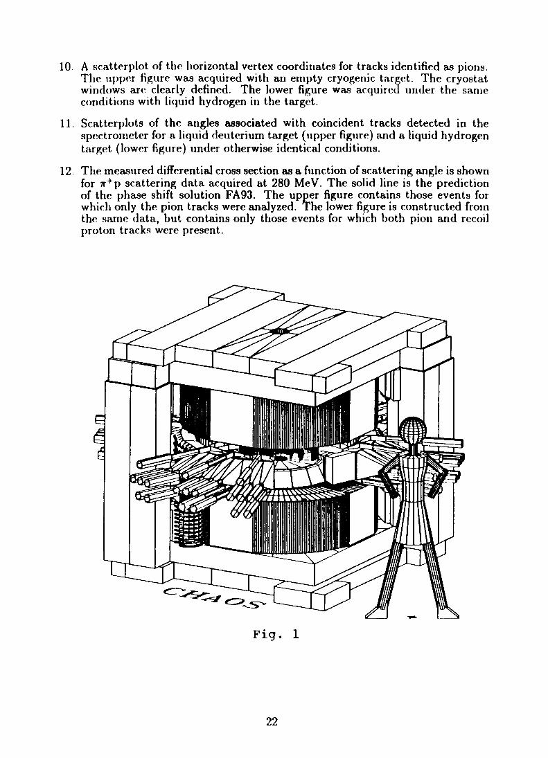
10. A scatterplot of the horizontal vertex coordinates for tracks identified as pions.The upper figure was acquired with an empty cryogenic target. The cryostatwindows arc clearly defined. The lower figure was acquired under the sameconditions with liquid hydrogen in the target.
11. Scatterplots of the angles associated with coincident tracks detected in thespectrometer for a liquid deuterium target (upper figure) and a liquid hydrogentarget (lower figure) under otherwise identical conditions.
12. The measured differential cross section as a function of scattering angle is shownfor 7r+p scattering data acquired at 280 MeV. The solid line is the predictionof the phase shift solution FA93. The upper figure contains those events forwhich only the pion tracks were analyzed. The lower figure is constructed fromthe same data, but contains only those events for which both pion and recoilproton tracks were present.
Fig. 1
22

to
B (T)
Radius
n
3
ob
o
20 40
CT> '
o -
a>'
/
100120
S io
o. . 1 .
/
i *
o
o
*
n
<
1 '
oen
. . i .
1 '
oCD
. . 1 .
1 ' 1 '
O N). . [ .
\
' ' 1

I5.75 mm
4JO SJO
Signal Signal H.V. Signal Signal
OAnode
• *— 73 mm • O
Cathode Anode
Fig . 5

V)
ou
500
400
300
200
100
-40
Fig . 6
WC4 left-right residuals
R C7t=2.2
20 0 20Residual (ns)
Fig. 7
40

500 -
0 -
-500 -
2 8 0 MeV 7T+n->n + 7T p (LD2> 0.5T)
Fig. 8
-500
Fig. 9
WOO/bO-iOO 2bO 0 250 MO 750 1000momanloin (M»V/c)

B6
150-
90
30
-30-
- 9 0
9 0 -
30-
-30-
-90-
150-
Target Empty
-
Target Full
-150 -90 -30 30
X (mm)
Fig . 1090 150
Angular Correlations360
160
Protons
LD2 Target
30 60 90 120 ISO 160
30 60 90 120 150 180 360
Fig. 11 Fig. 12