vol. 2 rule 5 well construction...
TRANSCRIPT

RULES & BYLAWS VOL. 2
RULE 5 WELL CONSTRUCTION
STANDARDS
Originally Adopted November 1, 1991
Revised
December 16, 2010, October 11, 2013 July 16, 2015

ii
(This page intentionally left blank)
iii
5. WELL CONSTRUCTION STANDARDS
TABLE OF CONTENTS 5-1 PURPOSE 1 5-2 DEFINITIONS 3 5-3 GENERAL 9 5-4 WELL LOCATION 9 5-5 WELL CONSTRUCTION 11
5-5.1 GENERAL REQUIREMENTS FOR ALL WELLS 11 5-5.2 WELLS IN THE FRESHWATER AND SALINE EDWARDS 15
MANAGEMENT ZONES 5-5.3 WELLS IN THE TRINITY AQUIFER MANAGEMENT ZONES 18
5-6 GEOPHYSICAL LOGGING AND REPORTING 19 5-7 WELL DEVELOPMENT 20 5-8 WELL DISINFECTION 20 5-9 WELL REPORTING 21 5-10 SPECIAL CONSTRUCTION STANDARDS FOR CLOSED LOOP 21
GEOTHERMAL WELLS 5-11 WELL PLUGGING 23
5-11.1 PLUGGING PLAN 23 5-11.2 PLUGGING REQUIREMENTS 23 5-11.3 PLUGGING REPORT 24
5-12 VARIANCES AND ALTERNATIVE PROCEDURES 25 FIGURES
FIGURE 1: MAP OF WELL CONSTRUCTION ZONES 1-2
FIGURE 2: EDWARDS MZ (WATER TABLE ZONE) 28 FIGURE 3: EDWARDS MZ (ARTESIAN AND SALINE ZONE) 29 FIGURE 4: UPPER TRINITY 30 FIGURE 5: MIDDLE TRINITY 31 FIGURE 6: LOWER TRINITY 32 FIGURE 7: TYPCIAL EDWARDS MZ WELL PLUGGING 33
APPENDIX – WELL CONSTRUCTION/PLUGGING SCHEMATICS 27

iv
(This page intentionally left blank)

1
RULE 5-1 PURPOSE The Barton Springs/Edwards Aquifer Conservation District (“District”) was created in 1987 by the 70th Texas Legislature under Senate Bill 988 (now codified at Special District Local Laws Code, Chapter 8802) and Chapter 52 (revised to Chapter 36) of the Texas Water Code (TWC). The District's mandate is to conserve, preserve, protect, and enhance the groundwater resources of the Barton Springs segment of the Edwards Aquifer and all other aquifers within the District boundaries. The District has been enabled with certain authorities, including the authority to adopt and enforce well construction standards, to achieve this statutory mandate. The District has developed these minimum well construction standards for the purpose of preserving and protecting the groundwater resources within the District’s jurisdiction and in recognition of the need to prevent groundwater waste and/or pollution that may occur as a result of inadequate well construction practices.

2
Figure 1 – Management Zones in the District’s jurisdictional area including the Shared Territory. The District has jurisdiction over the Edwards Aquifer only within the area excluding the Shared Territory (top panel). The District has jurisdiction over the Trinity and all other non-Edwards aquifers in the area including the Shared Territory (bottom panel). District jurisdiction in the Shared territory is limited to non-Edwards aquifers.
3
RULE 5-2 DEFINITIONS “Abandoned Well” - a well that has not been used for a beneficial purpose for at least six
consecutive months and/or a well not registered with the District. A well is considered to be in use in the following cases:
(1) a non-deteriorated well which contains the casing, pump and pump column in
good condition; (2) a non-deteriorated well which has been capped; (3) the well is used in the normal course and scope and with the intensity
and frequency of other similar users in the general community; or (4) the owner is participating in the Conservation Reserve Program authorized
by Sections 1231-1236, Food Security Act of 1985 (16 U.S.C. Sections 3831-3836), or a similar governmental program.
“Annular Seal” - the impermeable material or grout emplaced in the annular space between the
borehole wall and the outermost casing to prevent the downhole movement of surface water or the vertical mixing of groundwater.
“Annular Space” - the space between the outermost casing and borehole wall. “Artesian Zone” - that part of the Edwards Aquifer where water is confined in the aquifer
under pressure so that the water will rise in the well casing or drilled hole above the bottom of the confining bed overlying the aquifer. This zone is coextensive with the part of the Edwards Aquifer that is downdip of the Recharge Zone (Figure 1).
“Atmospheric Barrier” - a section of cement emplaced from two (2) feet below land surface to
the land surface when using granular sodium bentonite as a casing sealant or plugging sealant in lieu of cement.
“Bentonite” - a sodium hydrous aluminum silicate clay mineral (montmorillonite) commercially
available in powdered, granular, or pellet form which is mixed with potable water and used for a variety of purposes including the stabilization of borehole walls during drilling, the control of potential or existing high fluid pressures encountered during drilling below a water table, and to provide a seal in the annular space between the well casing and borehole wall.
“Casing” - a watertight pipe which is installed in an excavated or drilled hole, temporarily or
permanently, to maintain the hole sidewalls against caving, advance the borehole, and in conjunction with cementing and/or bentonite grouting, to confine the ground waters to their respective zones of origin, and to prevent surface contaminant infiltration.
“Closed Loop Geothermal Well” - a vertical closed system well used to circulate water, and
other fluids or gases through the earth as a heat source or heat sink.

4
“Confining Bed” - a body of impermeable or distinctly less permeable material stratigraphically adjacent to one or more aquifers.
“Critical Environmental Feature” - a feature such as a sinkhole, fault, or fracture that is a point
recharge source for an aquifer. “District” - the Barton Springs/Edwards Aquifer Conservation District (BSEACD). “Domestic Use”- water used by, and connected to a household for personal needs or for
household purposes such as drinking, bathing, heating, cooking, sanitation or cleaning, and landscape irrigation. Ancillary use may include watering of domestic animals.
“Domestic Well” - a well providing groundwater for domestic use. “Driller” - any person licensed in the state of Texas for well drilling and construction in
accordance with the Texas Occupations Code Chapter 1901, “Water Well Drillers” as amended.
“Drilling Authorization” - an authorization issued by the District for the drilling or
modification of a well.
“Eastern Freshwater Edwards Management Zone” - the management zone that includes the Edwards Aquifer and the portion of the Upper Trinity Aquifer where there is significant hydrological connection to the overlying Edwards Aquifer located between (1) the eastern boundary of the Western Freshwater Edwards Management Zone, generally corresponding to the Edwards Aquifer’s saturated thickness of approximately 100 feet and certain structural boundaries, and (2) the western boundary of the Saline Edwards Management Zone, generally corresponding to the so-called “bad water line.” This zone only applies to the area described in Special District Local Laws Code Section 8802.003 which excludes the Shared Territory (Figure 2).
“Edwards Aquifer” - the water-bearing zone comprised of the Edwards Group and associated limestone formations.
“Edwards Group and Associated Limestone Formations” - includes the Cretaceous-age
Edwards Group (Kainer and Person Formations) and the overlying Georgetown Formation. “Edwards Outcrop” - the Edwards and associated limestone formations found at the surface. This area is generally referred to as the Edwards Aquifer Recharge Zone.
“Freshwater Edwards Management Zones” - a collective term for the two management zones of the Freshwater Edwards Aquifer, viz., Western Freshwater Edwards Management Zone and Eastern Freshwater Edwards Management Zone. This zone only applies to the area described in Special District Local Laws Code Section 8802.003 which excludes the Shared Territory (Figure 2).
5
“Groundwater or Underground Water” - water percolating or otherwise able to move located beneath the earth's surface; by statute, this excludes but does not include water co- produced with oil and gas extraction and production.
“Grout” - a fluid mixture of the following types of materials of a consistency that can be forced
through a pipe to permanently plug wells or to be emplaced in the annular space between the borehole and the casing to form an impermeable annular seal.
(1) Cement grout - a neat portland or construction cement mixture of not more
than seven gallons of water per 94-pound sack of dry cement, or a cement that contains cement along with bentonite, gypsum or other additives.
(2) Bentonite grout - a fluid mixture of sodium bentonite and potable water mixed
at manufacturer’s specifications to a slurry consistency that can be pumped through a pipe directly into the annular space between the casing and the borehole wall. Its primary function is to seal the annular space in order to prevent the vertical subsurface migration or communication of fluids in the annular space.
(3) Cement-bentonite grout - a mixture of one (1) 94-pound sack of dry cement to 7
½ gallons of clean water and 2% to 6% bentonite (by weight 2 to 6 pounds) to increase fluidity and to control shrinkage.
“Grouting” - the act of emplacing grout by an authorized grout placement method. “Hand Dug Well” - wells with a diameter greater than thirty-six (36) inches and less than 100 feet
in depth installed by hand digging or by auger drilling are considered to be hand dug wells.
“Lower Trinity Aquifer” - an aquifer comprising the Sligo and Hosston Members of the Travis
Peak Formation.
“Lower Trinity Management Zone” - the management zone that is composed of the Lower Trinity Aquifer.
“Limited Production Permit (LPP)” - A domestic or livestock well authorized for use in accordance with District Rule 3-1-.20B. (A nonexempt well.)
“Meter” - a water flow measurement device which meets American Water Works Association (AWWA) standards for the line size, pressures, and flows, and which is properly installed according to the manufacturer's specifications, or other measuring device approved by the District capable of measuring the actual volume of water pumped and maintaining a cumulative record of measured flows.
“Middle Trinity Aquifer” - an aquifer comprising the Lower member of the Glen Rose
Limestone, and the Hensell Sand and Cow Creek Limestone Members of the Travis Peak Formation.

6
“Middle Trinity Management Zone” – the management zone that comprises principally the Middle Trinity Aquifer, except that the upper boundary of this zone is defined to exclude elevated Ca-SO4 water-bearing units in the upper portion of the Lower Glen Rose; this boundary may also be coincident with the top of a “reef” unit in the upper portions of the Lower Glen Rose Formation (when present).
“Multi-user Well” – A non-public water supply well that is used within the District to provide
water for beneficial use and is shared by the well owner and multiple property owners other than the well owner.
“New Well” - any well that is not an existing well or any existing well which has been modified to increase water production after August 13, 1987.
“Nonexempt Well” - a well required to obtain a permit for the production of groundwater from
within the District and required to report groundwater use. “Positive Displacement - Exterior Method” - a grout placement method whereby grout
emplaced by a positive displacement method such as pumping or forced injection after water or other drilling fluid has been circulated in the annular space sufficient to clear obstructions. A grout placement pipe shall be lowered to the bottom of the annular space or zone being grouted and raised slowly as the grout is introduced. The pipe shall be kept full continuously from start to finish of the grouting procedure, with the discharge end of the pipe being continuously submerged in the grout until the annular space is completely filled. In the event of interruption in the grouting operations, the bottom of the pipe shall be raised above the grout level and shall not be re-submerged until all air or water has been displaced from the pipe and the pipe flushed clean with clear water.
“Positive Displacement - Interior Method” - a grout placement method whereby a measured
quantity of grout, sufficient to fill the annular space shall be pumped into the casing, after water or other drilling fluid has been circulated in the annular space sufficient to clear obstructions. A drillable plug constructed of plastic or other suitable material shall be inserted on top of the grout. The plug will be forced down the casing using either water or drilling rods and therefore forcing the plug to the bottom of the casing. Pressure shall be maintained for a minimum of 24 hours or until such time as the sample of the grout indicates a satisfactory set.
“Potable Water” - water that is safe for human consumption in that it is free from impurities in
amounts sufficient to cause disease or harmful physiological effects. For purposes of these Rules, water may be rendered potable by adding chlorine bleach at the rate of one (1) gallon of bleach for every 500 gallons of water.
“Plugging” - the absolute sealing of a well bore in accordance with approved District standards. “Recharge Zone” - Generally, that area where the stratigraphic units constituting the Edwards
Aquifer crop out, including the outcrops of other geologic formations in proximity to the Edwards Aquifer, where caves, sinkholes, faults, fractures, or other permeable features would create a potential for recharge of waters from the surface into the Edwards Aquifer. The recharge zone is identified as that area designated by the Texas Commission

7
on Environmental Quality on the agency’s official maps.
“Saline Edwards Management Zone” - the management zone that includes the Edwards Aquifer east of a designated boundary line corresponding to points where its water chemistry generally comprises total dissolved solids concentrations of 1,000 mg/L, colloquially known as the “bad water line” (Figures 1 and 2).
“Sanitary Well Seal” - a watertight device to maintain a junction between the casing and the
pump column which prohibits liquids or solutions, including water, from entering the well through the well head and potentially contaminating the well.
“Shared Territory” - the territory described by Special Districts Local Laws Section 8802.0035 which includes the area inside the boundaries of the Edwards Aquifer Authority and Hays County but not within the boundaries of the Plum Creek Conservation District as the boundaries existed on February 1, 2015. The District has jurisdiction over groundwater and any wells drilled to produce water from any aquifer other than the Edwards Aquifer in the Shared Territory (see figure 1).
“Surface Completion” - sealing off access of undesirable water, surface material, or other potential sources of contamination to the well bore by proper casing and/or grouting procedures.
“Target Production Zone” - the zone in which the proposed well will be completed to produce
groundwater. The target production zone shall either be: the Freshwater Edwards aquifer, the Saline Edwards aquifer, the Upper Trinity aquifer, the Middle Trinity aquifer, or the Lower Trinity aquifer.
“Test Well” - a well that is constructed to be used solely for hydrogeological evaluation of the
aquifer(s) and assessment of prospective uses of water. (A nonexempt well.) “Tremie Method” - a grout placement method whereby a tremie pipe is lowered to the bottom
of the annular space or zone being grouted and raised slowly as the grout is introduced. The tremie pipe shall be kept full continuously from start to finish of the grouting procedure, with the discharge end of the tremie pipe being continuously submerged in the grout until the annular space is completely filled. This method is also known as the “Positive Displacement - Exterior Method.”
“Tremie Pipe” - a tubular device that carries materials to a designated depth in the hole. “Trinity Group Aquifer” - includes: the Upper Member of the Glen Rose Formation, known as
the Upper Trinity; the Lower Member of the Glen Rose Formation, and the Hensel Sand and Cow Creek Limestone Members of the Travis Peak Formation, known as the Middle Trinity; and the Sligo and Hosston Members of the Travis Peak Formation, known as the Lower Trinity.
“Upper Trinity Aquifer” - an aquifer comprising the upper member of the Glen Rose Limestone.

8
“Upper Trinity Management Zone” - the management zone that is composed of the Upper Trinity Aquifer.
“Undesirable Water” - water that is injurious to human health and the environment or water that can cause pollution to land or other waters.
“Void” - a general term for pore space or other openings in rock. The openings can vary from
very small to cave size, and are filled with water below the water table. “Water Table” - the upper boundary of the saturated zone in an unconfined aquifer. “Water Table Zone” - that part of the Edwards Aquifer confined only by atmospheric pressure.
This zone is coextensive with the area designated by the Texas Commission on Environmental Quality as Recharge Zone (Figure 1).
“Western Freshwater Edwards Management Zone” - the management zone that includes the
Edwards and the portion of the Upper Trinity Aquifer where there is significant hydrological connection to the overlying Edwards Aquifer. The zone encompasses the area west of a designated boundary line corresponding generally to the Edwards Aquifer’s saturated thickness of approximately 100 feet and/or in certain nearby areas by the surface traces of larger-throw faults. This zone only applies to the area described in Special District Local Laws Code Section 8802.003 which excludes the Shared Territory (Figure 2).
9
RULE 5-3 GENERAL Construction of wells and installation of pumps shall be performed by a licensed driller or pump installer in accordance with the Texas Occupations Code Chapter 1901, “Water Well Drillers” and Chapter 1902, “Water Well Pump Installers,” as amended, and the Administrative Rules of the Texas Department of Licensing and Regulation, 16 Texas Administrative Code, Chapter 76, as amended, and as specified by these District standards. The standards of the Texas Commission on Environmental Quality under 30 TAC, Chapter 290 and any other local, state, or federal regulations that may be more stringent than these District standards shall be adhered to where applicable. Additionally, any unique situation may require construction to go beyond these minimum standards in order to protect groundwater sources.
RULE 5-4 WELL LOCATION
A. Except in the case of monitoring and dewatering wells, which may be located
where necessity dictates, all wells shall be located in compliance with the following minimum horizontal distances:
(1) 150 feet from any possible source of potential contamination which includes, but is not limited to existing or proposed livestock or poultry yards, cemeteries, pesticide mixing and loading facilities, dry litter poultry facilities, privies, and underground and aboveground storage tanks used to contain static hydrocarbons or hazardous substances. If a possible source of potential contamination is an existing abandoned well located on same property, the existing well must be plugged in accordance with Rule 3-5 and 5-11. If it is to remain in service, it must be brought up to current District standards and registered with the District.
(2) 150 feet from any existing or proposed septic system absorption fields,
septic system spray areas, water-tight sewage and liquid- waste collection facilities, existing wells, or Critical Environmental Features.
(3) 50 feet from any property line. Exception to this rule is allowed where
platted or deed restricted subdivisions regulate spacing of wells and on-site sewage systems or public wastewater treatment is provided and utilized by the landowner. Wells subject to this exception shall maintain a minimum horizontal distance of five feet from any property line.
B. Wells shall not be located at a site location that is generally subject to flooding.
C. Wells shall not be located at a site generally subject to high traffic or in an area of
heavy construction activity. Where such a location is the only available location due to site constraints, the well head shall be protected with well- marked and easily visible barriers to provide sufficient protection to prevent possible damage from an impact or collision.
10
D. All well locations are subject to inspection and approval according to the District's Rules and staff’s concurrence regarding the specific well location.
E. Variances. Variance may be approved by the General Manager or designated
representative to allow for a decrease in the minimum horizontal distances specified in 5-4(A) provided that no other site is available on the property due to property size constraints and not due to the location chosen for the septic system, drain field or other possible sources of contamination. Variances shall only be approved if the proposed well completion and setback distance is sufficient to prevent contamination.
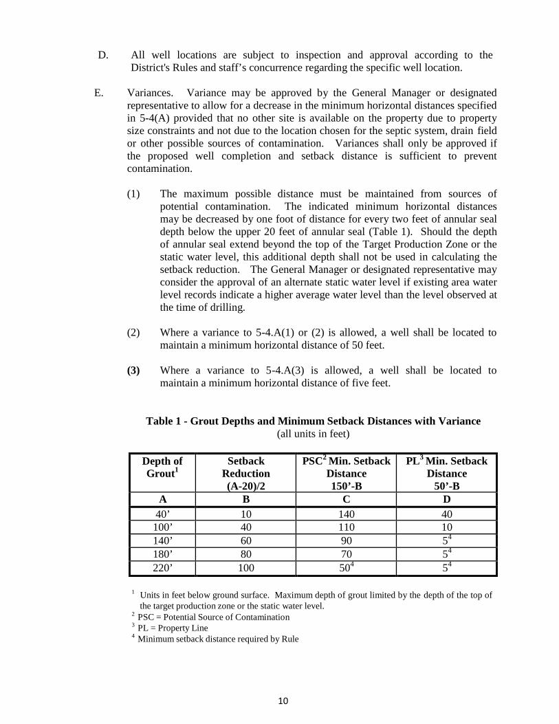
(1) The maximum possible distance must be maintained from sources of
potential contamination. The indicated minimum horizontal distances may be decreased by one foot of distance for every two feet of annular seal depth below the upper 20 feet of annular seal (Table 1). Should the depth of annular seal extend beyond the top of the Target Production Zone or the static water level, this additional depth shall not be used in calculating the setback reduction. The General Manager or designated representative may consider the approval of an alternate static water level if existing area water level records indicate a higher average water level than the level observed at the time of drilling.
(2) Where a variance to 5-4.A(1) or (2) is allowed, a well shall be located to
maintain a minimum horizontal distance of 50 feet.
(3) Where a variance to 5-4.A(3) is allowed, a well shall be located to maintain a minimum horizontal distance of five feet.
Table 1 - Grout Depths and Minimum Setback Distances with Variance
(all units in feet)
Depth of Grout1
Setback Reduction (A-20)/2
PSC2 Min. Setback Distance 150’-B
PL3 Min. Setback Distance
50’-B A B C D
40’ 10 140 40 100’ 40 110 10 140’ 60 90 54 180’ 80 70 54 220’ 100 504 54
1 Units in feet below ground surface. Maximum depth of grout limited by the depth of the top of
the target production zone or the static water level. 2 PSC = Potential Source of Contamination 3 PL = Property Line 4 Minimum setback distance required by Rule
11
RULE 5-5 WELL CONSTRUCTION 5-5.1 GENERAL REQUIREMENTS FOR ALL WELLS
A. DRILLING AND CASING
(1) With assistance from the licensed water well driller, the applicant shall
specifically identify the Target Production Zone in the Drilling Authorization application. The applicant shall specify the Target Production Zone to be either: the Freshwater Edwards aquifer, the Saline Edwards aquifer, the Upper Trinity aquifer, the Middle Trinity aquifer, or the Lower Trinity aquifer. Upon review of the Well Drilling Authorization application and prior to application approval, the District shall specify the maximum allowable drilling depth based on the Target Production Zone identified in the application and the minimum drilling and casing depths in accordance with the specified requirements for each target production zone. Each well shall be completed in accordance with these drilling and casing specifications with some variance allowed based on conditions experienced in the field.
(2) Any drilling fluids used to facilitate the drilling process shall be limited to
Potable Water only. If fluid additives are used, such additives shall be limited to the list of acceptable additives as defined in American Water Works Association (AWWA) Standards for water wells and shall be utilized in accordance with recognized drilling industry standards and practices.
(3) After drilling of the well has commenced, the wellbore shall not be left
unsealed or open to allow commingling between aquifers or production zones that differ in chemical quality for a period greater than 14 calendar days.
(4) All casing shall comply with the following requirements:
a. Casing used for domestic wells shall have a minimum inside diameter of 4 ½ inches.
b. The casing shall have the proper collapse strength and be strong enough to resist the pressures exerted by the surrounding materials, forces imposed on it during installation, and corrosion by soil and water environments.
(5) All steel casing shall be new and shall comply with the minimum
specifications outlined in the current AWWA Standards for water wells. Use of previously used casing is prohibited.

12
(6) All PVC casing shall be National Sanitation Foundation (NSF-WC) or American Society of Testing Material (ASTM) F-480 minimum SDR-17 approved water well casing.
(7) Monitoring wells may use other materials, such as fluoropolymer (Teflon),
glass-fiber-reinforced epoxy, or various stainless steel alloys.
B. ANNULAR SPACE
(1) For all exempt and ( L P P ) wells, the diameter of the borehole from the surface to the designated casing depth shall be a minimum of 3 ¾ inches larger than the outside diameter of the outermost well casing. (Example: use of 4 ½ inch SDR 17 PVC casing with an outside diameter of 5 inches would require a minimum 8 ¾ inch-diameter borehole).
(2) For all other nonexempt wells, the diameter of the borehole from the
surface to the designated casing depth shall be a minimum of 4 inches larger than the outside diameter of the outermost well casing. (Example: use of 5-inch nominal Schedule 10 steel casing with an outside diameter of 5 ½ inches would require a minimum 9 ½ inch-diameter borehole).
(3) All casing shall be centered such that there is an equal distance of annular
space from all points on the casing for the entire length of the annular seal interval.
(4) Annular space requirements for all wells without specified standards in
this rule (including but not limited to: alluvial wells, monitor wells, test wells, and certain exempt wells) shall, at minimum, be constructed to comply with State minimum standards. Other more stringent standards, to be determined by the District on a case-by-case basis, may also be required if necessary for groundwater quality protection and preservation.
C. GROUTING AND ANNULAR SEAL
(1) All wells shall be completed in and open only to the specified Target
Production Zone within the defined management zone. (2) The annular space around the outermost casing shall be grouted and sealed
to the depth of the specified annular seal intervals. (3) All wells shall be constructed such that there is no commingling between
aquifers or production zones that differ in chemical quality in order to prevent the quality degradation of any aquifer or zone.
(4) Any existing well that is determined to be or have the potential to be a
source of pollution or quality degradation due to commingling of aquifers or production zones that differ in chemical quality shall be retrofitted and
13
recompleted to these standards (if feasible and practical) or plugged and abandoned.
(5) Wells completed to produce undesirable water or constituents shall be
cased and sealed to prevent the mixing of water or constituent zones. (6) Each well shall be grouted and sealed in accordance with the specified
annular sealing requirements for each Target Production Zone. The total volume of grout to be used shall be calculated to be equal to 150% of the borehole-casing annulus volume for the specified annular seal interval. The initial volume of grout emplaced shall be equal to 110% of the borehole-casing annulus volume with the remaining volume to be used only if needed to reach the required depth or to observe returns to the surface. After emplacement of this initial volume of grout, the depth to the top of the annular seal shall be determined. If the required depth has not been reached, the remaining volume shall be used. If the required annular seal is still not achieved, the District may consider proposals for the use of alternate materials (such as granular bentonite, bentonite chips, or disinfected sand or gravel) to bridge through the voids and highly permeable intervals. Such proposals shall be considered on a case-by-case basis and shall not be implemented without prior approval from the District.
(7) Grout shall be emplaced by either the positive displacement interior or
exterior method (i.e. pumped under pressure). (8) Grout material shall consist of Cement grout, Bentonite grout, or Cement-
Bentonite grout and shall be mixed according to manufacturers specifications. When Bentonite or Cement-Bentonite grout is used for annular sealing or plugging, the annular seal or well bore shall be topped with at least two feet of cement grout to serve as an atmospheric barrier.
(9) Bentonite grout may not be used if the formation water to be sealed off or
the mixing water has chloride concentrations above 1,500 mg/l, total hardness concentrations (Ca++ & Mg++) above 500 mg/l, or if hydrocarbons are present.
(10) Sulfate resistant grout (Type V or Class H cement) shall be used for the
annular seal to seal off all water-bearing units producing waters with sulfate (SO4) concentrations above 1,500 mg/l. The annular seal interval shall be sufficient to provide an impermeable seal above and below the zone producing elevated sulfates. An alternative cementitious material providing equivalent protection to severe sulfate exposure may be utilized with prior approval from the General Manager or designated representative.
14
(11) Grouting and sealing requirements for all wells without specified standards in this rule (including but not limited to: alluvial wells, monitor wells, test wells, and certain exempt wells) shall, at minimum, be constructed to comply with State minimum standards. Other more stringent standards, to be determined by the District on a case-by-case basis, may also be required if necessary for groundwater quality protection and preservation.
D. SURFACE COMPLETION
(1) All wells using plastic casing shall be constructed with a steel sleeve or a
concrete slab or sealing block.
a. A concrete slab or sealing block shall:
i. be placed above the cement slurry around the well at the ground surface;
ii. extend laterally at least two feet from the well in all
directions and have a minimum thickness of four inches; iii. be separated from the well casing by a plastic or mastic coating
or sleeve to prevent bonding of the slab to the casing; and iv. be sloped to drain away from the well.
b. A steel sleeve shall:
i. be a minimum of 3/16 inches in thickness; ii. be at least 24 inches in length and extend at least 12 inches into
the cement; iii. be at a minimum of two inches larger in diameter than the
outside diameter of the outermost well casing and centered such that there is an equal distance of annular space from all points on the casing.
iv. have a minimal radial thickness of one inch from all points on
the casing; and v. have the annular space between the sleeve and the well casing
filled entirely with cement.
(2) Pitless adaptors may be used in accordance with 16 TAC §76.1000.
(3) The top of the casing shall extend a minimum of 12 inches above the land surface or the slab/sealing block.
15
(4) The well head of all wells shall be completed with a watertight sanitary well seal. The seal shall have at least a ¾ inch unobstructed inspection port with a threaded well plug positioned to allow unrestricted access into the well with a water level measuring device.
(5) Except for (LPP) wells, all new nonexempt wells and all existing
nonexempt wells upon pump replacement servicing shall be equipped with a Sch. 40 PVC pipe extending from the surface inspection port to just above the pump assembly. This pipe must have an internal diameter of at least one (1) inch, be screened and vented to allow normal fluctuation of the water level, be capped on the bottom and at the surface, and allow unrestricted access into the well with a water level measuring device.
(6) For all exempt and ( LPP)wells, the use of drop-pipe stabilizers or other
devices that may obstruct free access to the water level with a water level measurement device is prohibited. Exception to this rule may be allowed with the installation of a water level measurement access pipe as required in Rule D(5) of this section.
(7) All wells shall be equipped with an easily accessible spigot/hose bib
located between the well and any downstream equipment (valves, flowmeters, tanks, chlorinators, filters, etc.).
(8) All nonexempt wells drilled after August 14, 1989 shall be equipped with a
water meter in accordance with District Rule 3-2.1. (9) Surface completion requirements for all wells without specified standards in
this rule (including but not limited to: alluvial wells, monitor wells, test wells, and certain exempt wells) shall, at minimum, be constructed to comply with State minimum standards. Other more stringent standards, to be determined by the District on a case-by-case basis, may also be required if necessary for groundwater quality protection and preservation.
5-5.2 WELLS IN THE FRESHWATER AND SALINE EDWARDS MANAGEMENT
ZONES
A. WATER TABLE ZONE WELLS (Figure 2). The following standards apply to wells located in the Water Table Zone and completed in and open only to the Freshwater Edwards Management Zones. The Water Table Zone is defined as that part of the aquifer confined only by atmospheric pressure.
(1) Drilling and Casing. All wells shall be drilled to a depth not to exceed the
base of the units of the Edwards Group and shall be cased to a minimum depth of 40 feet below the land surface or at or near the depth of the static water level in the well, whichever is deeper. The General Manager or designated representative may extend the maximum total depth into strata below the base of the units of the Edwards Group where

16
there is evidence of hydrologic communication. The General Manager or designated representative may also consider the approval of an alternate static water level if existing area water level records indicate a higher average water level than the level observed at the time of drilling.
(2) Grouting and Annular Seal. For all wells, a volume of grout shall be
emplaced to fill the entire depth of the borehole-casing annulus from the determined static water level up to the land surface. The General Manager or designated representative may consider the approval of an alternate static water level if existing area water level records indicate a higher average water level than the level observed at the time of drilling. In areas where “circulation loss” problems are anticipated or have occurred, the driller shall adhere to the grouting requirements of 5-5.1.C(6) of this section and may request consideration of the use of alternate materials if necessary.
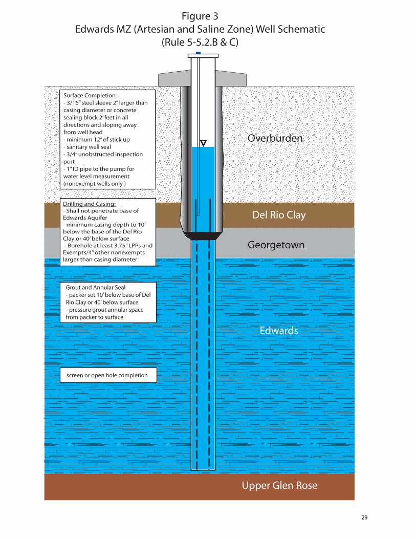
B. ARTESIAN ZONE WELLS (Figure 3). The following standards apply to wells
located in the Artesian Zone and completed in and open only to the Freshwater Edwards Management Zones. The Artesian Zone is defined as the zone where water is confined in an aquifer under pressure so that the water will rise in the well casing or drilled hole above the bottom of the confining bed overlying the aquifer.
(1) Drilling and Casing. All wells shall be drilled to a depth not to exceed the
base of the units of the Edwards Group and shall be cased to a minimum depth of 40 feet below the land surface or ten feet below the base of the Del Rio Clay, whichever is deeper.
(2) Grouting and Annular Seal.
a. For all wells, a volume of grout shall be emplaced to fill the entire
depth of the borehole-casing annulus from ten feet below the base of the Del Rio Clay or 40 feet below the land surface, whichever is deeper, back up to the land surface.
b. In areas where “circulation loss” problems are anticipated or have
occurred within the Edwards Group, the driller shall adhere to the grouting requirements of 5-5.1.C(6) of this section and may request consideration of the use of alternate materials if necessary.
. C. SALINE ZONE WELLS (Figure 3). The following standards apply to wells to be
completed in and open only to the Saline Edwards Management Zone. The Saline Edwards Management Zone is defined as the management zone that includes the Edwards aquifer east of a designated boundary line corresponding to points where its water chemistry generally comprises total dissolved solids concentrations of 1,000 mg/L, colloquially known as the “bad water line.”

17
(1) Drilling and Casing. All wells shall be drilled to a depth not to exceed the base of the units of the Edwards Group and shall be cased to a minimum depth of ten (10) feet below the base of the Del Rio Clay.
(2) Grouting and Annular Seal.
a. For all wells, a volume of grout shall be emplaced to fill the
borehole-casing annulus from a depth of ten feet below the base of the Del Rio Clay back up to the land surface.
b. Grout emplaced for the annular seal shall comply with 5-5.1.C(9)
of this section related to sealing off zones of elevated chlorides.
(3) All Saline Zone Wells completed to produce undesirable water shall be cased and sealed to prevent the mixing of water or constituent zones in accordance with 5-5.1.C(5) of this section.
D. UPPER TRINITY AQUIFER WELLS (Figure 4). The following standards apply
to wells to be completed in and open only to the Upper Trinity Aquifer within the Upper Trini ty Management Zones. The Upper Trinity Aquifer is defined as the aquifer comprising the upper member of the Glen Rose Limestone.
(1) Drilling and Casing. All wells shall be drilled to a depth not to exceed the
base of the upper member of the Glen Rose Limestone and shall be cased to minimum depth of 200 feet below the base of the Edwards Group.
(2) Grouting and Annular Seal.
a. For all wells, a volume of grout shall be emplaced to fill the
borehole-casing annulus from a depth of 200 feet below the top of the uppermost member of the Glen Rose Limestone.
b. In areas where circulation loss problems are anticipated or have
occurred within the Edwards Group, the driller shall adhere to the grouting requirements of 5-5.1.C(6) of this section and may request consideration of the use of alternate materials if necessary.
c. Grout emplaced for the annular seal shall comply with 5-
5.1.C(9)&(10) of this section related to sealing off zones of elevated total hardness and sulfates.
(3) All Upper Trinity Aquifer Wells completed to produce undesirable water
shall be cased and sealed to prevent the mixing of water or constituent zones in accordance with 5-5.1.C(5) of this section.

18
5-5.3 WELLS IN THE TRINITY AQUIFER MANAGEMENT ZONES
A. MIDDLE TRINITY WELLS (Figure 5). The following standards apply to wells to be completed in and open only to the Middle Trinity Management Zone. The Middle Trinity Management Zone is comprised principally of the Middle Trinity Aquifer excluding the elevated Ca-SO4 water-bearing units in the upper portion of the Lower Glen Rose; this boundary may also be coincident with the top of a “reef” unit in the upper portions of the Lower Glen Rose Formation (when present).
(1) Drilling and Casing. All wells shall be drilled to a depth not to exceed the
base of the units of the Middle Trinity Aquifer and shall be cased to the base of the elevated Ca-SO4 water-bearing units in the upper portion of the Lower Glen Rose formation just above the top of a “reef” unit in the upper portions of the Lower Glen Rose Formation, if present.
(2) Grouting and Annular Seal.
a. A volume of grout shall be emplaced to fill the entire depth of the
borehole-annulus of the casing from the base of the elevated Ca- SO4 water-bearing units in the upper portion of the Lower Glen Rose just above the top of a “reef” unit in the upper portions of the Lower Glen Rose Formation (when present) back to the land surface.
b. In areas where “circulation loss” problems are anticipated or have
occurred within the Edwards Group, the driller shall adhere to the grouting requirements of 5-5.1.C(6) of this section and may request consideration of the use of alternate materials if necessary.
c. Grout emplaced for the annular seal shall comply with 5-
5.1.C(9)&(10) of this section related to sealing off zones of elevated total hardness and sulfates.
B. LOWER TRINITY WELLS (Figure 6). The following standards apply to wells
to be completed in and open only to the Lower Trinity Management Zone. The Lower Trinity Management Zone composed of the Lower Trinity Aquifer which is an aquifer comprising the Sligo and Hosston Members of the Travis Peak Formation.
(1) Drilling and Casing. All wells shall be drilled to a depth not to exceed the
base of the units of the Lower Trinity Aquifer and shall be cased to the top of the Lower Trinity Aquifer or the base of Hammett Shale.
(2) Grouting and Annular Seal.
19
a. A volume of grout shall be emplaced to fill the entire depth of the borehole-annulus casing from the top of the Lower Trinity Aquifer (base of the Hammet Shale) back to the land surface.
b. In areas where “circulation loss” problems are anticipated or have
occurred, the driller shall adhere to the grouting requirements of 5- 5.1.C(6) of this section and may request consideration of the use of alternate materials if necessary.
c. Grout emplaced for the annular seal shall comply with 5-
5.1.C(9)&(10) of this section related to sealing off zones of elevated total hardness and sulfates.
C. HYBRID MIDDLE/LOWER TRINITY WELLS. Wells completed in and open
to both the Middle and Lower Trinity Target Production Zones are generally prohibited. Exception to this rule may be considered on a case-by-case basis and may only be allowed with an acceptable demonstration to the General Manager or designated representative that such production will cause no harm in terms of quality or quantity to either aquifer.
RULE 5-6 GEOPHYSICAL LOGGING AND REPORTING
For all wells completed in the Trinity Aquifer Management Zones and all nonexempt wells completed in the Edwards Aquifer Management Zones, geophysical logs shall be run to provide qualitative information on aquifer characteristics and groundwater quality prior to completion.
A. The results of the logging shall be presented to District staff for the purposes of
identifying the pertinent geologic picks necessary for determining drilling, casing, and grouting depths and intervals in accordance with the standards specified for each Target Production Zone in Rule 5-5.2 and 5-5.3.
B. The geophysical logs shall include a caliper log and an electrical log with shallow
and deep investigative curves (e.g., 16-inch short normal/64-inch long normal resistivity curves or induction log) with a spontaneous potential curve and natural gamma.
C. A copy of all geophysical logs run shall be provided to the District in both paper
copy and electronic format within 60 days of well completion. The logs shall be of industry acceptable quality with complete headings including well elevation and coordinates.

20
RULE 5-7 WELL DEVELOPMENT
A. All wells shall be properly developed for the removal of cuttings, silt and other such materials forced into fractures, bedding planes and other openings in the wall of the hole during the drilling process.
B. Acceptable methods of well development include: pumping, surging, or hydraulic
jetting.
(1) The pumping method shall be performed by pumping the well continually at a rate of 1 ½ to 2 times the design capacity of the pump, to be installed, for a period of no less than 2 hours (4 to 10 hours recommended).
(2) The surging method shall be performed by operating a surge plunger,
surge block or bailer up and down in the casing like a piston in a cylinder.
(3) The hydraulic jetting or backwashing method shall be accomplished using high velocity jets of water from a high pressure pump directed horizontally out a jet nozzle into the production zone. Upon completion of the development work, the well should be cleaned to the bottom.
RULE 5-8 WELL DISINFECTION
A. Unless waived by written request from the landowner, a new, repaired, or
reconditioned well or pump installation or repair on a well used to supply water for human consumption shall be properly disinfected as required by the AWWA, pursuant to ANSI/AWWA A100-06. The well shall be properly disinfected with a chlorine solution or other appropriate disinfecting agent under the circumstances. A disinfecting solution with a minimum equivalent concentration of 50 milligrams per liter (mg/l) of available chlorine shall be placed in the well as required by the AWWA, pursuant to ANST/AWWA C654 and the United States Environmental Protection Agency (EPA).
B. Proper disinfection shall be accomplished by:
(1) treating the water in the well casing to provide an average disinfectant
residual to the entire volume of water in the well casing of 50 mg/l; this may be accomplished by the addition of a chlorine solution or sodium hypochlorite solution in the prescribed amounts;
(2) circulating, to the extent possible, the disinfected water in the well casing
and pump column to insure that the disinfectant is well mixed; and
(3) pumping the well to remove disinfected water for a minimum of 15 minutes.

21
RULE 5-9 WELL REPORTING
The State of Texas Well Report, any pump test data, water level data, water quality data, or any other data pertinent to a well shall be submitted to the District office within 60 days of the date of the completion or cessation of drilling, deepening, or otherwise altering a well. For Well Reports submitted electronically, the assigned tracking number shall be submitted to the District within 60 days.
RULE 5-10 SPECIAL CONSTRUCTION STANDARDS FOR CLOSED LOOP GEOTHERMAL WELLS
A. GENERAL. All wells drilled for the purpose of providing the earth coupling for
a closed loop circulating system of a heating/cooling system shall be drilled and completed in accordance with these rules and standards. More stringent standards may be required on the basis of accepted industry standards or unique site conditions. Permits shall be issued with special requirements pertaining to the operation of the Closed Loop Geothermal Wells. All wells in a closed loop circulating system must be spaced a minimum of ten feet apart.
B. INSTALLATION. For a closed loop circulating system, the circulation loop to be
placed in the well shall be constructed of a material and in such a way as to prevent leakage, and not cause contamination to the aquifer from construction techniques employed. The circulation loop shall be tested prior to installation and again after backfilling has been completed. Testing shall consist of maintaining a pressure in the circulation loop at least two and one-half times the designed system operating pressure for a minimum of 24 hours prior to installation and for six hours following installation and backfilling. Records of each test shall be kept by the contractor, and will include time and pressure data. Test data shall be submitted to the District prior to initializing system. Installation of the circulating loop shall be accomplished under the supervision of a Texas licensed driller.
C. GROUTING. The circulating loop shall be backfilled below the water level with
a clean, disinfected (in accordance with industry standards) mixture of sand and gravel, which shall be at least 50% sand. When the backfill reaches ten feet above the water level, a mixture consisting of at least 20% Bentonite by volume shall be used as backfill, extending to 40 feet below the ground surface, or the bottom of the trench in which the lines will be run, whichever is deeper. The remainder of the well shall be grouted in accordance with Rule 5-5.1.C.
D. CLOSURE. Should a well need to be abandoned due to encountering a void or
cavern unsuitable to backfilling, the well shall be abandoned in accordance with Rule 5-11. In addition, a free standing plug shall be installed within five (5) feet of the void or cavern, and the well shall be backfilled and plugged in accordance with the adopted District Well Plugging Procedures.
22
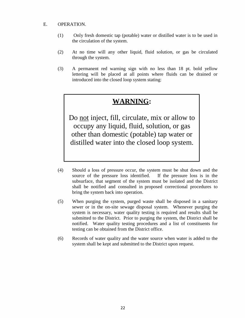
E. OPERATION.
(1) Only fresh domestic tap (potable) water or distilled water is to be used in the circulation of the system.
(2) At no time will any other liquid, fluid solution, or gas be circulated
through the system.
(3) A permanent red warning sign with no less than 18 pt. bold yellow lettering will be placed at all points where fluids can be drained or introduced into the closed loop system stating:
WARNING:
Do not inject, fill, circulate, mix or allow to occupy any liquid, fluid, solution, or gas
other than domestic (potable) tap water or distilled water into the closed loop system.
(4) Should a loss of pressure occur, the system must be shut down and the
source of the pressure loss identified. If the pressure loss is in the subsurface, that segment of the system must be isolated and the District shall be notified and consulted in proposed correctional procedures to bring the system back into operation.
(5) When purging the system, purged waste shall be disposed in a sanitary
sewer or in the on-site sewage disposal system. Whenever purging the system is necessary, water quality testing is required and results shall be submitted to the District. Prior to purging the system, the District shall be notified. Water quality testing procedures and a list of constituents for testing can be obtained from the District office.
(6) Records of water quality and the water source when water is added to the
system shall be kept and submitted to the District upon request.

23
RULE 5-11 WELL PLUGGING 5-11.1 PLUGGING PLANS
Each contemplated well plugging must be site-inspected by the District staff and shall require a plugging plan be submitted in writing with the application and approved by the District General M anager or designated representative prior to commencement of plugging activities. The District shall have ten days from the day of plan submittal to review and approve or disapprove the proposed plan. Specifics of each well plugging will be discussed with the applicant and considered prior to approval or disapproval. Additional requirements beyond the minimum plugging requirements may be included in the plugging plan approval to address site-specific considerations. The well plugging shall be performed in strict adherence to these standards and any additional requirements of the approved plugging plan.
5-11.2 PLUGGING REQUIREMENTS
A. All abandoned wells must be plugged by a driller or under the direct supervision
of a designated staff member of the District in accordance with the approved plugging plan and the following procedure (Figure 7):
(1) All removable casing shall be removed from the well.
a. If it is not practicable to remove the casing, then the well casing shall be perforated to assure placement of an effective seal.
(2) Any existing surface completion shall be removed.
(3) Wells in the Freshwater and Saline Edwards Management Zones:
a. In the Water Table Zone, the well/borehole shall be partially filled with a well-washed, disinfected sand or gravel to a level ten (10) feet above the static water level or to forty (40) feet below the land surface, whichever is deeper. The General Manager or designated representative may consider the approval of an alternate static water level if existing area water level records indicate a higher average water level than the level observed at the time of plugging.
b. In the Artesian and Saline Edwards Zones, the well/borehole shall
be partially filled with a well-washed, disinfected sand or gravel to a level ten (10) feet below the Del Rio Clay/Georgetown contact (top of the Edwards Group) or to forty (40) feet below the land surface, whichever is deeper.
c. The well/borehole shall be pressure filled via a tremie pipe with
grout from the top of the gravel/sand interval back up to the land surface. When Bentonite or Cement-Bentonite grout is used, the

24
well shall be topped with at least two feet of cement grout to serve as an atmospheric barrier.
(4) Wells in the Trinity Aquifer Management Zones. All wells that penetrate
the base of the Edwards Group shall be pressure filled via a tremie pipe with grout from the bottom up to fifty (50) feet above the base of the units of the Edwards Group. The remainder of the well/borehole shall be plugged in accordance with Rule 5-11.2.A(3) of this section.
B. HAND DUG WELLS. Large hand dug and bored wells 36-inches or greater in
diameter to one hundred (100) feet in depth may be plugged in accordance with the following procedure (Figure 7):
(1) Any debris or other man-made material that can be readily and safely
extracted shall be removed from the well.
(2) If the well contains standing water, it shall be chlorinated by adding chlorine bleach at a rate of one (1) gallon of bleach for every five hundred (500) gallons of standing water.
(3) Any casing or cement, tile, rock, or brick wall used for lining the upper
portion of the well shall be removed.
(4) The well shall be backfilled with compacted clay or caliche to a point three (3) feet below land surface. For hand dug wells that encounter voids or enlarged solution cavities; sand, gravel, or cobbles may be placed in the well to block off such voids prior to placement of compacted clay.
(5) The remainder of the well shall be filled with soil comparable to that of
the adjacent area and mounded above the surrounding surface to compensate for settling. For hand dug wells that encounter voids or enlarged solution cavities, the top of the well shall be filled with cement or concrete to one (1) foot below the surface, topped with soil comparable to that of the adjacent area, and mounded above the surrounding surface to compensate for settling. Alternatively, the cement or concrete cap may be poured level with the land surface.
C. GROUT REQUIREMENTS.
(1) Grout material shall consist of Cement grout, Bentonite Grout, or Cement- Bentonite grout and shall be mixed according to manufacturers’ specifications. When Bentonite or Cement-Bentonite grout is used for the annular seal to the land surface, the annular seal shall be topped with at least two (2) feet of cement grout to serve as an atmospheric barrier.
(2) Bentonite grout may not be used if the formation water to be sealed off or
the mixing water contains chloride concentrations above 1,500 mg/l, total hardness concentrations (Ca++ & Mg++) above 500 mg/l, or if hydrocarbons are present.
25
(3) Sulfate resistant grout (Type V cement) shall be used for plugging all
wells producing water with sulfate concentrations above 1,500 mg/l. An alternative cementitious material providing equivalent protection to severe sulfate exposure may be utilized with prior approval from the General Manager or designated representative.
5-11.3 PLUGGING REPORT
The State of Texas Plugging Report and any other data pertinent to the well shall be submitted to the District office within 30 days after the plugging is complete. For Plugging Reports submitted electronically, the assigned tracking number shall be submitted to the District within 30 days.
5-12 VARIANCES AND ALTERNATIVE PROCEDURES
A. If the applicant for a Drilling Authorization or the applicant’s designated
representative finds any of the requirements or procedures prescribed by these Rules unworkable or inadequate, a variance allowing combinations of the prescribed standards or procedures or alternative procedures may be employed upon approval of the General Manager or designated representative, provided that the proposal will prevent injury and pollution. The General Manager will not approve an alternative proposal that is less protective than the standards and procedures stated elsewhere in these rules.
B. Proposals to use combinations of prescribed requirements or procedures or
alternative requirements or procedures shall be submitted to the District for approval prior to their implementation.
C. If the General Manager approves such an alternative proposal, it shall not relieve
the party from the obligation to comply with other applicable requirements of federal, state, or local law.
26
(This page intentionally left blank)
27
Appendix
Well Construction/Plugging Schematics
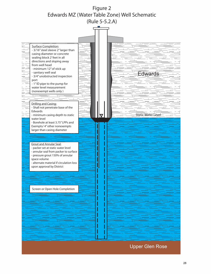
Figure 2Edwards MZ (Water Table Zone) Well Schematic
(Rule 5-5.2.A)
Drilling and Casing: - Shall not penetrate base of the Edwards- minimum casing depth to static water level- Borehole at least 3.75” LPPs and Exempts/ 4” other nonexempts larger than casing diameter
Upper Glen Rose
Grout and Annular Seal:- packer set at static water level- annular seal from packer to surface- pressure grout 150% of annular space volume- alternate material if circulation loss upon approval by District
Edwards
Static Water Level
Screen or Open Hole Completion
Surface Completion:- 3/16” steel sleeve 2” larger than casing diameter or concrete sealing block 2’ feet in all directions and sloping away from well head- minimum 12” of stick up- sanitary well seal- 3/4” unobstructed inspection port- 1” ID pipe to the pump for water level measurement (nonexempt wells only )
28
Surface Completion:- 3/16” steel sleeve 2” larger than casing diameter or concrete sealing block 2’ feet in all directions and sloping away from well head- minimum 12” of stick up- sanitary well seal- 3/4” unobstructed inspection port- 1” ID pipe to the pump for water level measurement (nonexempt wells only )
Figure 3Edwards MZ (Artesian and Saline Zone) Well Schematic
(Rule 5-5.2.B & C)
Georgetown
Edwards
Overburden
Del Rio Clay
Upper Glen Rose
Drilling and Casing: - Shall not penetrate base of Edwards Aquifer- minimum casing depth to 10’ below the base of the Del Rio Clay or 40’ below surface - Borehole at least 3.75” LPPs and Exempts/4” other nonexempts larger than casing diameter
Grout and Annular Seal:- packer set 10’ below base of Del Rio Clay or 40’ below surface- pressure grout annular space from packer to surface
screen or open hole completion
29

Figure 4Upper Trinity Aquifer Well Schematic
(Rule 5-5.2.D)
GeorgetownDel Rio Clay
Overburden
Upper Glen Rose
Lower Glen Rose (Elevated CaSO4 Zone)
Hammet Shale
Drilling and Casing: - Shall not penetrate base of Upper Trinity Aquifer- minimum casing depth to 200’ below the base of Edwards Group - Borehole at least 3.75” LPPs and Exempts/4” other nonexempts larger than casing diameter
Reef (if present)
Edwards
Grout and Annular Seal:- packer set 200’ below the base of the Edwards Group- annular seal from packer to surface- sulfate resistant grout required through elevated sulfate zone- pressure grout 150% of annular space volume- alternate material through Edwards if circulation loss upon approval by District
screen or open hole completion
Surface Completion:- 3/16” steel sleeve 2” larger than casing diameter or concrete sealing block 2’ feet in all directions and sloping away from well head- minimum 12” of stick up- sanitary well seal- 3/4” unobstructed inspection port- 1” ID pipe to the pump for water level measurement (nonexempt wells only )
Cow Creek
Upp
er T
rinity
~450
ft. t
hick
Edw
ards
Aqu
ifer
~450
ft. t
hick
Mid
dle
Trin
ity~
375
ft. th
ick
Low
er T
rinity
~2
80 ft
. thi
ck
30
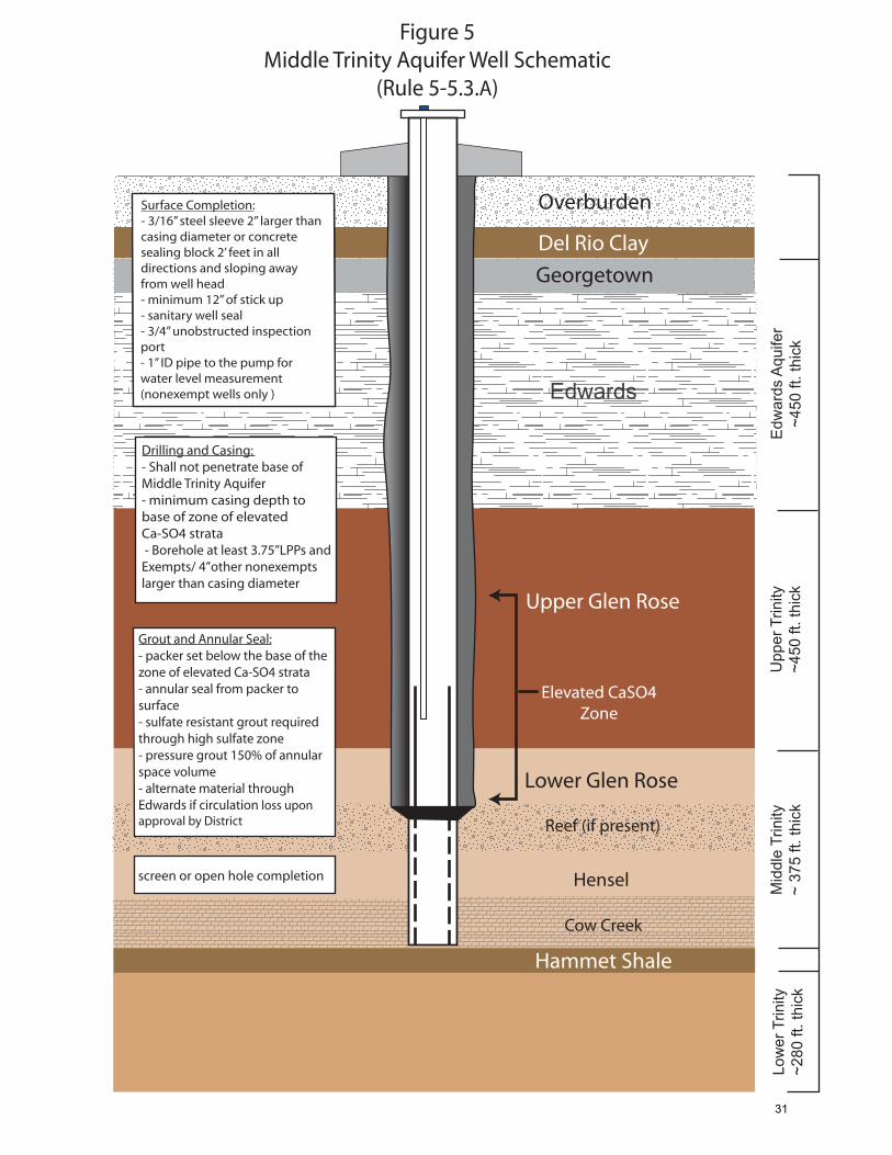
Figure 5Middle Trinity Aquifer Well Schematic
(Rule 5-5.3.A)
Georgetown
Del Rio Clay
Overburden
Hensel
Hammet Shale
Edw
ards
Aqu
ifer
~450
ft. t
hick
Upp
er T
rinity
~450
ft. t
hick
Mid
dle
Trin
ity~
375
ft. th
ick
Low
er T
rinity
~2
80 ft
. thi
ck
Reef (if present)
Surface Completion:- 3/16” steel sleeve 2” larger than casing diameter or concrete sealing block 2’ feet in all directions and sloping away from well head- minimum 12” of stick up- sanitary well seal- 3/4” unobstructed inspection port- 1” ID pipe to the pump for water level measurement (nonexempt wells only )
Drilling and Casing: - Shall not penetrate base of Middle Trinity Aquifer- minimum casing depth to base of zone of elevated Ca-SO4 strata - Borehole at least 3.75”LPPs and Exempts/ 4”other nonexempts larger than casing diameter
screen or open hole completion
Grout and Annular Seal:- packer set below the base of the zone of elevated Ca-SO4 strata- annular seal from packer to surface- sulfate resistant grout required through high sulfate zone- pressure grout 150% of annular space volume- alternate material through Edwards if circulation loss upon approval by District
Edwards
Surface Completion:- 3/16” steel sleeve 2” larger than casing diameter or concrete sealing block 2’ feet in all directions and sloping away from well head- minimum 12” of stick up- sanitary well seal- 3/4” unobstructed inspection port- 1” ID pipe to the pump for water level measurement (nonexempt wells only )
Cow Creek
Upper Glen Rose
Elevated CaSO4 Zone
Lower Glen Rose
31

Figure 6Lower Trinity Aquifer Well Schematic
(Rule 5-5.3.B)
GeorgetownDel Rio Clay
Overburden
Upper Glen Rose
Lower Glen Rose
Hammet Shale
Drilling and Casing: - Shall not penetrate base of Lower Trinity Aquifer- minimum casing depth to base of Hammet Shale - Borehole at least 3.75” LPPs and Exempts/4” other nonexempts larger than casing diameter
Reef (if present)
Edwards
screen or open hole completion
Grout and Annular Seal:- packer set below the base of the Hammet Shale- annular seal from packer to surface- sulfate resistant grout required through elevated sulfate zone- pressure grout 150% of annular space volume- alternate material through Edwards if circulation loss upon approval by District
Surface Completion:- 3/16” steel sleeve 2” larger than casing diameter or concrete sealing block 2’ feet in all directions and sloping away from well head- minimum 12” of stick up- sanitary well seal- 3/4” unobstructed inspection port- 1” ID pipe to the pump for water level measurement (nonexempt wells only )
Cow Creek
Upp
er T
rinity
~450
ft. t
hick
Edw
ards
Aqu
ifer
~450
ft. t
hick
Mid
dle
Trin
ity~
375
ft. th
ick
Low
er T
rinity
~2
80 ft
. thi
ck
Elevated CaSO4 Zone
Hensel
32

Surface Completion- remove all surface completion including slab and enclosures- remove all removable casing- at minimum, cut off top of casing from below grade
Figure 7Typical Edwards Well Plugging Schematic
(Rule 5-11)
Georgetown
Edwards
Overburden
Del Rio Clay
Upper Glen Rose
Grout - pressure grout from depth of sand/gravel interval to the surface.- 2’ cement cap as atmospheric barrier if bentonite used
- establish total depth
Edwards Section:- fill with well-washed, disinfected (chlorinated) sand or gravel from bottom to either:10’ below the Del Rio Clay, 10’ above the static water level, or 40’ below the surface, whichever is deeper.
33