voip over 1xev-do revision a cdg voip summit · recommend optimizations, acceptable tradeoffs c....
TRANSCRIPT

VoIP over 1xEv-DO Revision ACDG VoIP SummitRobert Kerr – Nortel
Sr. Manager – Access Product EvolutionSan Diego, Feb 8 ‘05

2
Presentation Topics
1. Why VoIP
2. Elements of a successful VoIP offering
3. VoIP capacity over DO Rev A
4. Voice Quality considerations
5. Signaling Analysis
6. Optimizing for VoIP deployment

3
Added value of VoIP over 1xEv-DO RevA> VoIP is just one practical application – solving the VoIP
challenge allows support of other revenue generating real time applications/services• Rich Services (gaming, video conferencing, etc.)
> Following the trends from the wireline industry• Ability to offer seamlessly integrated and easy to use real time
data services such as VoIP Strengthens competitive position among wireless operators
> Enables a standalone 1xEv-DO RevA network with both broadband data and voice.• Reduced Complexity in the network by duplication of functions
> Enables a single carrier to support voice & data versus a dedicated voice & dedicated data carrier.
> Simplified Network maintenance, seamless services integration & a richer end user experience
VoIP is a leading practical real time data application Paving the way for other new revenue generating services

4
Key Challenges in Commercializing VoIP
> End to End QoS and Policy Enforcement between access and core• Must be able to correlate billing records with QoS and service
authorization
> Network Performance• Capacity • User experience: Call setup times, voice quality • In network vs. out of network performance
> Security Management• Firewall Traversals, Denial of Service attacks, Virus Protection,
VPN Management
> Regulatory Issues• CALEA, E911, WPS, etc…
VoIP over DO 1xEv-DO RevA requires an End-to-End solution extending all the way through the network
5
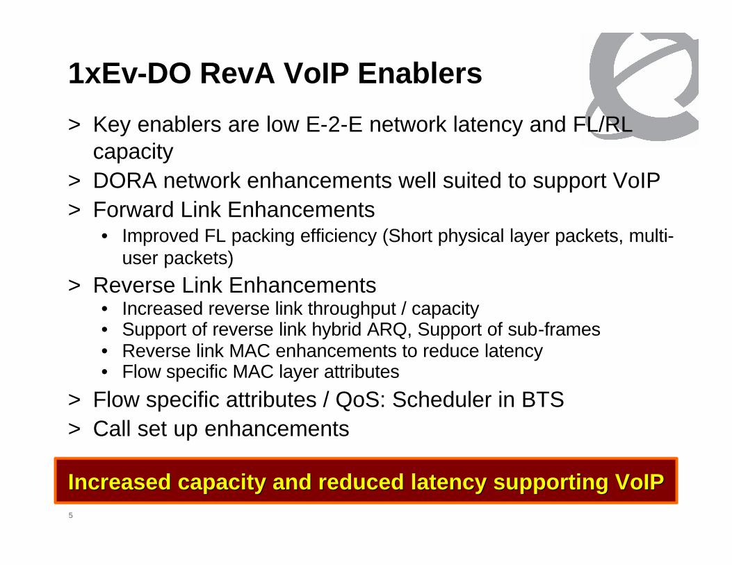
1xEv-DO RevA VoIP Enablers
> Key enablers are low E-2-E network latency and FL/RL capacity
> DORA network enhancements well suited to support VoIP> Forward Link Enhancements
• Improved FL packing efficiency (Short physical layer packets, multi-user packets)
> Reverse Link Enhancements• Increased reverse link throughput / capacity• Support of reverse link hybrid ARQ, Support of sub-frames• Reverse link MAC enhancements to reduce latency• Flow specific MAC layer attributes
> Flow specific attributes / QoS: Scheduler in BTS> Call set up enhancements
Increased capacity and reduced latency supporting VoIPIncreased capacity and reduced latency supporting VoIP

6
VoIP requires End-2-End Network analysis
D. Network Latency Identify existing Network nodal bottlenecks, provide latency guidelines for leased or home network resources
E. Handoffs Analyze / document required handoff mechanisms
F. Core interactions Billing considerations Security (Net. Addr. translation, Firewall traversal)
G. Quality of ServiceDefine E-2-E network QoS flow, QoS negotiation mechanisms
Nortel Analysis A. VoIP Capacity
End-2-End capacity analysis Packet Data network capacity, congestion, bottlenecks analysis
B. VoIP QualityAssess impact on VoIP Voice quality Recommend optimizations, acceptable tradeoffs
C. Signaling assessmentMessaging obstacles (# mess., length)Standards based optimization Call set up delay too long
Nortel has completed VoIP analysis and is focusing on required standards based optimizations

7
Overall Capacity Summary 2% per-user outage in FL, No PPP overhead
VoIP capacity is Reverse link limited – Projected capacity of ~40 Users per Carrier-sector
50-6030-3520-2510-15
110110110110 30303030Airlink delay (ms)
10-20~ 10< 10< 10Capacity
YesNoYesNo1/8-rate frame blanking
Dual receive antennaSingle receive antenna
50-6030-3520-2510-15
110110110110 30303030Airlink delay (ms)
10-20~ 10< 10< 10Capacity
YesNoYesNo1/8-rate frame blanking
Dual receive antennaSingle receive antenna
FL (Land-to-Mobile)
RL (Mobile-to-Land)
38
60
Yes
30
60
No
12-Slot Termination
90904040Airlink delay (ms)
39322921Capacity
YesNoYesNo1/8-rate frame blanking
16-Slot Termination8-slot Termination
38
60
Yes
30
60
No
12-Slot Termination
90904040Airlink delay (ms)
39322921Capacity
YesNoYesNo1/8-rate frame blanking
16-Slot Termination8-slot Termination

8
Call Quality / Delay Analysis
> Delay is not only parameter to consider in Voice quality analysis
> ITU-T G.107 incrementally looks at MOS score to understand user experience
Voice quality impact of delayDO to landline
DO-DO calls: In a closed DO network
DO to 1x: Requires TrFO* to mitigate delay. 2 wireless links + vocoding
optimize delay
Need to optimize delay
Acceptable
Network delay ranges from “acceptable” to “Needs optimization”for the various call models. Delay critical to voice quality
DO toLand
DO toDO
DO to1x
DO to1X trfo*
Mobile call model
DO Rev A1xRTT
74 76
5963
5561
4045
5055
60
6570
75
80
DO toLand
1x toLand
DO to DO 1x to 1x DO to 1xwithout
TrFO
DO to 1xwith TrFO
-4
0
11
Del
ay
Tolerable delay threshold

9
Signaling Assessment Overview> The assessment examines the call setup delays that can be
anticipated for VoIP calls in a 1xEv-DO Rev A based Multimedia Domain (MMD) network.
> Our analysis is focused on 3 particular end to end call types1. AT Handset to AT handset (i.e. Mobile to Mobile)
• AT implies DORA handset with a VoIP client2. AT Handset to Landline (PSTN)3. At Handset to 1xRTT phone (inter-technology Mobile to Mobile scenario)
> Two 1xRTT based call types are included for comparative purposes.
1. 1xRTT MS to 1xRTT MS (i.e. Mobile to Mobile)2. 1xRTT MS to Landline (PSTN)
> In looking at call setup delays, the focus is on the time from the caller pressing “Send” to the caller hearing ring-back. This ringing provides assurance that the call is working and effectively restarts their mental timer.

10
I-CSCF
Visited2Home2Home1Visited1Message Flow example – AT to AT
UserBPDSNPDSN
+ RNBTSDOM RN+
BTSDOMHA
Route Update (ACH)AC Ack (CC)
Connection Request (ACH)
Traffic Channel Assignment (CC)
Traffic Channel Complete (RTC)RTC Ack (FTC)
Pilot + DRC (RTC)
ASHSS
P-CSCF S-CSCF I-CSCFS-CSCF
P-CSCF
TCP:SYNC – (port 5060)
HA
(A)Dormant
ToActive
TCP:SYNC – (port 5060)TCP:SYNC+ACK – (port 5060)TCP:ACK – (port 5060)
TCP**Connection 1
SIPINVITE
TCP**Connection 2
TCP:SYNC+ACK – (port 5060)TCP:ACK – (port 5060)
TCP:SYNC – (port 5060)
SIP INVITE(Cont’d)
Traffic Channel Assignment (CC)
RTC Ack (FTC)Pilot + DRC (RTC)
Traffic Channel Complete (RTC)
(B)D to A
TCP**Connection 2
(Cont’d)
*
Preconditions: Both User A and User B terminals have been powered on, and have registered with the DO & Packet Data Core Networks and the SIP Server. Neither terminal has an RF link at the time of the call.
UserA
* For clarity, reverse direction “100 Trying” messages, in response to “Invites”, are not shown.** TCP signaling shown. If UDP is chosen, there is no equivalent UDP messaging.
verification of session ownership
I-CSCF gets S-CSCF from HSS(2)
AS access for “A”would occur here if included in timings.
S-CSCF determines correct Home2 I-
CSCF from HSS(1)
If UDP is used, the SIP Invite reaching the RNC triggers the
Traffic Channel setup.**The Invite then proceeds to the AT.
AC Ack (CC)Route Update (ACH)
Page
AS access for “B”would occur here if included in timings.
Example of extensive invite
messaging from terminal
A to terminal B

11
I-CSCF
SIP 200 OK(to INVITE)
SIP ACK
Message Flow - AT to AT - continuedUser
AUser
BPDSNPDSN+ RN
BTSDOM RN+
BTSDOMHA
ASHSS
P-CSCF S-CSCF I-CSCFS-CSCF
P-CSCF HA
SIP 180Ringing
SIP PRACK
Example: Messaging leads to 8.5 sec call set up delay
SIP 183
SIP UPDATE
SIP PRACK
SIP 200 OK
SIP 200 OK
SIP 200 OK
Authorize QoSResources
Authorize QoSResources
UE Resource Reservation
Visited2Home2Home1Visited1
Ring-back
Alerting
UE Resource Reservation. Messaging between UE and P-CSCF.
Answer
Media FlowMedia FlowP-CSCF enables
Media flow at PDSN.
P-CSCF enables Media flow at PDSN.

12
Example Result for Post Dial Delay
5.4
8.0
4.23.7
2.5
0.4
0.5
0.20.3
0.1
0.0
1.0
2.0
3.0
4.0
5.0
6.0
7.0
8.0
9.0
AT to 1x AT to AT AT to Land 1x to 1x 1x to Land
Call Types
Sec
onds
(PAD) Post Answer Delay
(PDD) Post Dial Delay
Local/National IPv4/v6 TCP/UDP ROHC SIP CompressionNational 4 UDP Yes Yes
Target ITU PDD for
National call.
Targeted interval
Industry Benchmark 1x CS voice
today
5.4
8.0
4.23.7
2.5
0.4
0.5
0.20.3
0.1
0.0
1.0
2.0
3.0
4.0
5.0
6.0
7.0
8.0
9.0
AT to 1x AT to AT AT to Land 1x to 1x 1x to Land
Call Types
Sec
onds
(PAD) Post Answer Delay
(PDD) Post Dial Delay
Local/National IPv4/v6 TCP/UDP ROHC SIP CompressionNational 4 UDP Yes Yes
Target ITU PDD for
National call.
Targeted interval
Targeted interval
Industry Benchmark 1x CS voice
today
Industry Benchmark 1x CS voice
today
Post Dial delay currently excessive due to signaling

13
Contributions to Post Dial Delay> In most cases, transport of the SIP messages over the air link
is the single largest contributor to PDD.
Local / NationalNationalIPv4/v6
4TCP/UDP
UDPROHC
YesSIP Compression
Yes
Post Dial Delay Breakdown
0.71.6
0.7
2.0
3.9
2.0
2.7
2.5
1.6
0.0
1.0
2.0
3.0
4.0
5.0
6.0
7.0
8.0
9.0
AT to 1x AT to AT AT to LandCall Type
Sec
onds
Core Network
Signaling over RF Link
Traffic Channel Setup
ITU reference
Target
Post Dial delay optimization opportunities are understood and being worked for future standards contributions

14
MMD based Signaling assessment Conclusions
> Post dial delays for VoIP calls using SIP based signaling are projected to be from 3 to 6.5 seconds longer than the accepted targets
> Expected call set up target of 3 seconds increases required optimization to between 5 and 8.5 seconds
> The actual call set up delay will vary depending on the call type and network assumptions.
> Of the AT originated call types, no network options achieved PDD targets for VoIP over DOrA calls with the exception of AT to Land calls.
> Nortel is making good progress internally on proposals to optimize the signaling and reduce the signaling delay.
Optimization of signaling should target maximum optimization while preserving SIP extensibility. How Signaling is
optimized/implemented has yet to be resolved.

15
Conclusions> Nortel VoIP Capacity simulations demonstrate VoIP over 1xEv-DO
RevA can provide 1X or greater capacity, and continued industryfocus is justified.
> Voice quality is challenged by network delay• Additional bearer path delay optimization would further enhance Voice Quality,
specifically for DO to 1x and DO to DO call models.
• Nortel has identified Key areas for delay improvement
> Signaling analysis: Problem areas requiring industry effort to resolve• Post dial delays for VoIP calls using MMD SIP based signaling are projected
to be from 0.1 to 8 seconds longer than the accepted targets
• None of the call types (e.g. AT to AT, AT to Land) or network options (e.g. IPv4 vs. IPv6) achieved Post Dial Delay targets for VoIP over DO RevA calls.
• Nortel is committed to defining Standards changes, or additions to the MMD SIP signaling architecture to support VoIP over DO RevA using an MMD architecture
VoIP over DO Rev A is a valid evolution path, meriting further industry focus to support over 1xEv-DO RevA

Thank you