vns therapy system physician’s manual therapy system physician's... · 2019-03-06 · 0344...
TRANSCRIPT

www.livanova.com
0344
VNS Therapy® SystemPhysician’s Manual
Pulse™ Generator—Model 102
Pulse Duo™ Generator—Model 102R
Demipulse® Generator—Model 103
Demipulse Duo® Generator—Model 104
AspireHC® Generator—Model 105
AspireSR® Generator—Model 106
Lead—Model 302
PerenniaFLEX® Lead—Model 304
PerenniaDURA® Lead—Model 303
For Healthcare Professionals
June 2018
Non-U.S. Version
76-0000-4900/1 (Non-U.S.)

VNS Therapy® System Physician’s Manual76-0000-4900/1 (Non-U.S.)
© Copyright 2014 - 2018 LivaNova, PLC, London UKAll rights reserved.
LivaNova is a registered United States trademark of LivaNova, PLC. NCP, Demipulse, Demipulse Duo, Perennia, VNS Therapy, AspireHC, PerenniaFLEX, PerenniaDURA, and AspireSR are registered United States trademarks of LivaNova USA, Inc. Pulse and Pulse Duo are trademarks of LivaNova USA, Inc. Corresponding foreign trademarks may also be registered or pending.
The year of authorization to affix the CE mark:102/102R - 2003103/104 - 2005105 - 2011106 - 2014302 - 2003303 - 2006304 - 2009
ii76-0000-4900/1 (Non-U.S.)

VNS Therapy® System Physician’s Manual76-0000-4900/1 (Non-U.S.)
Table of Contents
1. INTRODUCTION TO THE VNS THERAPY SYSTEM . . . . . . . . . . . . . . . . 2
1.1. Brief Device Description . . . . . . . . . . . . . . . . . . . . . . . . . . . . . . . . . . . . . . . 21.1.1. The VNS Therapy System . . . . . . . . . . . . . . . . . . . . . . . . . . . . . . . . 21.1.2. Package Contents . . . . . . . . . . . . . . . . . . . . . . . . . . . . . . . . . . . . . . 2
1.2. Intended Use / Indications . . . . . . . . . . . . . . . . . . . . . . . . . . . . . . . . . . . . . 31.2.1. Depression . . . . . . . . . . . . . . . . . . . . . . . . . . . . . . . . . . . . . . . . . . . 31.2.2. Epilepsy . . . . . . . . . . . . . . . . . . . . . . . . . . . . . . . . . . . . . . . . . . . . . . 3
1.2.2.1. Screening for Ictal Tachycardia . . . . . . . . . . . . . . . . . . . . 31.3. Contraindications . . . . . . . . . . . . . . . . . . . . . . . . . . . . . . . . . . . . . . . . . . . . 41.4. Warnings . . . . . . . . . . . . . . . . . . . . . . . . . . . . . . . . . . . . . . . . . . . . . . . . . . 51.5. Precautions . . . . . . . . . . . . . . . . . . . . . . . . . . . . . . . . . . . . . . . . . . . . . . . 10
1.5.1. General . . . . . . . . . . . . . . . . . . . . . . . . . . . . . . . . . . . . . . . . . . . . . 101.5.2. Sterilization, Storage, and Handling . . . . . . . . . . . . . . . . . . . . . . . 141.5.3. Lead Evaluation and Connection . . . . . . . . . . . . . . . . . . . . . . . . . . 151.5.4. Environmental and Medical Therapy Hazards . . . . . . . . . . . . . . . . 15
1.5.4.1. Hospital and medical environments . . . . . . . . . . . . . . . . 151.5.4.2. Home occupational environments . . . . . . . . . . . . . . . . . 171.5.4.3. Cellular phones . . . . . . . . . . . . . . . . . . . . . . . . . . . . . . . 171.5.4.4. Other environmental hazards . . . . . . . . . . . . . . . . . . . . 181.5.4.5. Programming software . . . . . . . . . . . . . . . . . . . . . . . . . . 181.5.4.6. Generator and EMI effects on other devices . . . . . . . . . 181.5.4.7. Effects on ECG monitors . . . . . . . . . . . . . . . . . . . . . . . . 191.5.4.8. Generator disposal . . . . . . . . . . . . . . . . . . . . . . . . . . . . 19
1.6. Education, Training, and Services . . . . . . . . . . . . . . . . . . . . . . . . . . . . . . 19
2. TECHNICAL INFORMATION — 102/102R GENERATORS . . . . . . . . . 22
2.1. Detailed Device Description . . . . . . . . . . . . . . . . . . . . . . . . . . . . . . . . . . . 222.1.1. Physical Characteristics . . . . . . . . . . . . . . . . . . . . . . . . . . . . . . . . 222.1.2. Power Source . . . . . . . . . . . . . . . . . . . . . . . . . . . . . . . . . . . . . . . . 222.1.3. Circuitry . . . . . . . . . . . . . . . . . . . . . . . . . . . . . . . . . . . . . . . . . . . . . 222.1.4. Identification . . . . . . . . . . . . . . . . . . . . . . . . . . . . . . . . . . . . . . . . . 24
2.2. VNS Therapy System Compatibility . . . . . . . . . . . . . . . . . . . . . . . . . . . . . 242.3. Directions for Use . . . . . . . . . . . . . . . . . . . . . . . . . . . . . . . . . . . . . . . . . . 25
2.3.1. Specifications and Product Information . . . . . . . . . . . . . . . . . . . . . 252.3.2. Operating Characteristics . . . . . . . . . . . . . . . . . . . . . . . . . . . . . . . 28
2.3.2.1. Communicating with the VNS Therapy System . . . . . . . 282.3.2.2. Stimulation . . . . . . . . . . . . . . . . . . . . . . . . . . . . . . . . . . . 28
2.3.2.2.1. Initiating stimulation with the magnet . . . . . 302.3.2.2.2. Inhibiting pulse generator output with a
magnet . . . . . . . . . . . . . . . . . . . . . . . . . . . . 322.3.2.2.3. Resetting the microprocessor using the
magnet and programming wand . . . . . . . . . 322.3.2.2.4. Effects of the daily reset of the internal
clock . . . . . . . . . . . . . . . . . . . . . . . . . . . . . . 332.3.2.3. Device history . . . . . . . . . . . . . . . . . . . . . . . . . . . . . . . . 342.3.2.4. Device diagnostics . . . . . . . . . . . . . . . . . . . . . . . . . . . . . 34
iii76-0000-4900/1 (Non-U.S.)

VNS Therapy® System Physician’s Manual76-0000-4900/1 (Non-U.S.)
2.3.2.4.1. Reasons for high lead impedance readings . . . . . . . . . . . . . . . . . . . . . . . . . . . 34
2.3.2.4.2. Short-circuit conditions within the lead . . . . 352.3.2.4.3. Lead problem troubleshooting . . . . . . . . . . 36
2.3.2.5. Delivery of programmed output current . . . . . . . . . . . . .362.3.2.6. Charge delivered per pulse . . . . . . . . . . . . . . . . . . . . . . .372.3.2.7. Effects of programmed settings on pulse generator
projected lifetime . . . . . . . . . . . . . . . . . . . . . . . . . . . . . . .382.3.2.7.1. Pulse generator replacement . . . . . . . . . . . 50
2.3.2.8. Lead lifetime and replacement . . . . . . . . . . . . . . . . . . . .502.3.2.9. End-of-service and replacement information . . . . . . . . .50
3. TECHNICAL INFORMATION — 103/104 GENERATORS . . . . . . . . . . 64
3.1. Detailed Device Description . . . . . . . . . . . . . . . . . . . . . . . . . . . . . . . . . . .643.1.1. Physical Characteristics . . . . . . . . . . . . . . . . . . . . . . . . . . . . . . . . .643.1.2. Biological Compatibility . . . . . . . . . . . . . . . . . . . . . . . . . . . . . . . . . .643.1.3. Power Source . . . . . . . . . . . . . . . . . . . . . . . . . . . . . . . . . . . . . . . . .643.1.4. Circuitry . . . . . . . . . . . . . . . . . . . . . . . . . . . . . . . . . . . . . . . . . . . . .643.1.5. Identification . . . . . . . . . . . . . . . . . . . . . . . . . . . . . . . . . . . . . . . . . .65
3.2. VNS Therapy System Compatibility . . . . . . . . . . . . . . . . . . . . . . . . . . . . .663.3. Directions for Use . . . . . . . . . . . . . . . . . . . . . . . . . . . . . . . . . . . . . . . . . . .67
3.3.1. Specifications and Product Information . . . . . . . . . . . . . . . . . . . . .673.3.2. Operating Characteristics . . . . . . . . . . . . . . . . . . . . . . . . . . . . . . . .68
3.3.2.1. Communicating with the VNS Therapy System . . . . . . .683.3.2.1.1. Programming software . . . . . . . . . . . . . . . . 683.3.2.1.2. Programming wand . . . . . . . . . . . . . . . . . . 683.3.2.1.3. Prompts and messages . . . . . . . . . . . . . . . 683.3.2.1.4. Communication . . . . . . . . . . . . . . . . . . . . . 693.3.2.1.5. Normal Mode . . . . . . . . . . . . . . . . . . . . . . . 693.3.2.1.6. Magnet Mode . . . . . . . . . . . . . . . . . . . . . . . 693.3.2.1.7. Pulse generator interrogation . . . . . . . . . . . 703.3.2.1.8. Programmable parameters. . . . . . . . . . . . . 703.3.2.1.9. Duty cycle. . . . . . . . . . . . . . . . . . . . . . . . . . 713.3.2.1.10. Parameter settings and battery life. . . . . . . 71
3.3.2.2. VNS Therapy magnets . . . . . . . . . . . . . . . . . . . . . . . . . .713.3.2.2.1. Service life of magnet. . . . . . . . . . . . . . . . . 733.3.2.2.2. Magnet activation technique
(epilepsy only) . . . . . . . . . . . . . . . . . . . . . . 733.3.2.2.3. Inhibit pulse generator output with the
magnet . . . . . . . . . . . . . . . . . . . . . . . . . . . . 733.3.2.2.4. Reset the microprocessor with the
magnet and the programming wand. . . . . . 743.3.2.3. Device history . . . . . . . . . . . . . . . . . . . . . . . . . . . . . . . . .743.3.2.4. Device diagnostics . . . . . . . . . . . . . . . . . . . . . . . . . . . . .74
3.3.2.4.1. System Diagnostics test . . . . . . . . . . . . . . . 753.3.2.4.2. Reasons for high or low lead impedance
readings . . . . . . . . . . . . . . . . . . . . . . . . . . . 753.3.2.4.3. High lead impedance: possible
implications. . . . . . . . . . . . . . . . . . . . . . . . . 763.3.2.4.4. Low lead Impedance: possible
implications. . . . . . . . . . . . . . . . . . . . . . . . . 763.3.2.4.5. Stimulus waveform analysis . . . . . . . . . . . . 76
3.3.2.5. Delivery of programmed output current . . . . . . . . . . . . .77
iv 76-0000-4900/1 (Non-U.S.)
VNS Therapy® System Physician’s Manual76-0000-4900/1 (Non-U.S.)
3.3.2.5.1. LOW as output current . . . . . . . . . . . . . . . . 773.3.2.5.2. Reprogram to a lower current . . . . . . . . . . . 77
3.3.2.6. Charge delivered per pulse . . . . . . . . . . . . . . . . . . . . . . 773.3.2.6.1. Output current x pulse width = charge
delivered per pulse . . . . . . . . . . . . . . . . . . . 773.3.2.7. Pulse generator battery longevity . . . . . . . . . . . . . . . . . 78
3.3.2.7.1. Battery longevity and programmed setting choices. . . . . . . . . . . . . . . . . . . . . . . 78
3.3.2.7.2. Battery status indicators . . . . . . . . . . . . . . . 793.3.3. Pulse Generator Replacement . . . . . . . . . . . . . . . . . . . . . . . . . . . 793.3.4. Lead Lifetime and Replacement . . . . . . . . . . . . . . . . . . . . . . . . . . 793.3.5. Signs of End of Service . . . . . . . . . . . . . . . . . . . . . . . . . . . . . . . . . 803.3.6. Replacement Based on Battery Status Indicators . . . . . . . . . . . . . 80
4. TECHNICAL INFORMATION — 105 GENERATOR . . . . . . . . . . . . . . . 82
4.1. Detailed Device Description . . . . . . . . . . . . . . . . . . . . . . . . . . . . . . . . . . . 824.1.1. Physical Characteristics . . . . . . . . . . . . . . . . . . . . . . . . . . . . . . . . 824.1.2. Biological Compatibility . . . . . . . . . . . . . . . . . . . . . . . . . . . . . . . . . 824.1.3. Power Source . . . . . . . . . . . . . . . . . . . . . . . . . . . . . . . . . . . . . . . . 824.1.4. Circuitry . . . . . . . . . . . . . . . . . . . . . . . . . . . . . . . . . . . . . . . . . . . . . 824.1.5. Identification . . . . . . . . . . . . . . . . . . . . . . . . . . . . . . . . . . . . . . . . . 83
4.2. VNS Therapy System Compatibility . . . . . . . . . . . . . . . . . . . . . . . . . . . . . 844.3. Directions for Use . . . . . . . . . . . . . . . . . . . . . . . . . . . . . . . . . . . . . . . . . . 84
4.3.1. Specifications and Product Information . . . . . . . . . . . . . . . . . . . . . 844.3.2. Operating Characteristics . . . . . . . . . . . . . . . . . . . . . . . . . . . . . . . 86
4.3.2.1. Communicating with the VNS Therapy System . . . . . . . 864.3.2.1.1. Programming software . . . . . . . . . . . . . . . . 864.3.2.1.2. Programming wand . . . . . . . . . . . . . . . . . . . 864.3.2.1.3. Prompts and messages. . . . . . . . . . . . . . . . 864.3.2.1.4. Communication . . . . . . . . . . . . . . . . . . . . . . 874.3.2.1.5. Normal Mode. . . . . . . . . . . . . . . . . . . . . . . . 874.3.2.1.6. Magnet Mode . . . . . . . . . . . . . . . . . . . . . . . 874.3.2.1.7. Pulse generator interrogation . . . . . . . . . . . 884.3.2.1.8. Programmable parameters . . . . . . . . . . . . . 884.3.2.1.9. Duty cycle . . . . . . . . . . . . . . . . . . . . . . . . . . 894.3.2.1.10. Parameter settings and battery life . . . . . . . 89
4.3.2.2. VNS Therapy magnets . . . . . . . . . . . . . . . . . . . . . . . . . 894.3.2.2.1. Service life of magnet . . . . . . . . . . . . . . . . . 914.3.2.2.2. Magnet activation technique
(epilepsy only) . . . . . . . . . . . . . . . . . . . . . . . 924.3.2.2.3. Inhibit pulse generator output with the
magnet . . . . . . . . . . . . . . . . . . . . . . . . . . . . 924.3.2.2.4. Reset the microprocessor with the
magnet and the programming wand . . . . . . 934.3.2.3. Device history . . . . . . . . . . . . . . . . . . . . . . . . . . . . . . . . 934.3.2.4. Device diagnostics . . . . . . . . . . . . . . . . . . . . . . . . . . . . . 93
4.3.2.4.1. System Diagnostics test . . . . . . . . . . . . . . . 944.3.2.4.2. Reasons for high or low lead impedance
readings. . . . . . . . . . . . . . . . . . . . . . . . . . . . 944.3.2.4.3. High lead impedance: possible
implications . . . . . . . . . . . . . . . . . . . . . . . . . 954.3.2.4.4. Low lead Impedance: possible
implications . . . . . . . . . . . . . . . . . . . . . . . . . 95
v76-0000-4900/1 (Non-U.S.)

VNS Therapy® System Physician’s Manual76-0000-4900/1 (Non-U.S.)
4.3.2.4.5. Stimulus waveform analysis . . . . . . . . . . . . 954.3.2.5. Delivery of programmed output current . . . . . . . . . . . . .96
4.3.2.5.1. LOW as output current . . . . . . . . . . . . . . . . 964.3.2.5.2. Reprogram to a lower current. . . . . . . . . . . 96
4.3.2.6. Charge delivered per pulse . . . . . . . . . . . . . . . . . . . . . . .964.3.2.6.1. Output current x pulse width = charge
delivered per pulse . . . . . . . . . . . . . . . . . . . 964.3.2.7. Pulse generator battery longevity . . . . . . . . . . . . . . . . . .97
4.3.2.7.1. Battery longevity and programmed setting choices . . . . . . . . . . . . . . . . . . . . . . 97
4.3.2.7.2. Battery status indicators . . . . . . . . . . . . . . . 984.3.3. Pulse Generator Replacement . . . . . . . . . . . . . . . . . . . . . . . . . . . .984.3.4. Lead Lifetime and Replacement . . . . . . . . . . . . . . . . . . . . . . . . . . .984.3.5. Signs of End of Service . . . . . . . . . . . . . . . . . . . . . . . . . . . . . . . . .994.3.6. Replacement Based on Battery Status Indicators . . . . . . . . . . . . .99
5. TECHNICAL INFORMATION — 106 GENERATOR . . . . . . . . . . . . . . 102
5.1. Detailed Device Description . . . . . . . . . . . . . . . . . . . . . . . . . . . . . . . . . .1025.1.1. Physical Characteristics . . . . . . . . . . . . . . . . . . . . . . . . . . . . . . . .1025.1.2. Biological Compatibility . . . . . . . . . . . . . . . . . . . . . . . . . . . . . . . . .1025.1.3. Power Source . . . . . . . . . . . . . . . . . . . . . . . . . . . . . . . . . . . . . . . .1025.1.4. Circuitry . . . . . . . . . . . . . . . . . . . . . . . . . . . . . . . . . . . . . . . . . . . .1025.1.5. Identification . . . . . . . . . . . . . . . . . . . . . . . . . . . . . . . . . . . . . . . . .103
5.2. VNS Therapy System Compatibility . . . . . . . . . . . . . . . . . . . . . . . . . . . .1045.3. Directions for Use . . . . . . . . . . . . . . . . . . . . . . . . . . . . . . . . . . . . . . . . . .104
5.3.1. Specifications and Product Information . . . . . . . . . . . . . . . . . . . .1045.3.2. Operating Characteristics . . . . . . . . . . . . . . . . . . . . . . . . . . . . . . .106
5.3.2.1. Communicating with the VNS Therapy System . . . . . .1065.3.2.1.1. Programming software . . . . . . . . . . . . . . . 1065.3.2.1.2. Programming wand . . . . . . . . . . . . . . . . . 1065.3.2.1.3. Prompts and messages . . . . . . . . . . . . . . 1065.3.2.1.4. Communication . . . . . . . . . . . . . . . . . . . . 1065.3.2.1.5. Normal Mode . . . . . . . . . . . . . . . . . . . . . . 1075.3.2.1.6. Magnet Mode . . . . . . . . . . . . . . . . . . . . . . 1075.3.2.1.7. AutoStim Mode. . . . . . . . . . . . . . . . . . . . . 1085.3.2.1.8. Pulse generator interrogation . . . . . . . . . . 1095.3.2.1.9. Programmable parameters. . . . . . . . . . . . 1105.3.2.1.10. Duty cycle. . . . . . . . . . . . . . . . . . . . . . . . . 1115.3.2.1.11. Parameter settings and battery life. . . . . . 111
5.3.2.2. VNS Therapy magnets . . . . . . . . . . . . . . . . . . . . . . . . .1125.3.2.2.1. Service life of magnet. . . . . . . . . . . . . . . . 1145.3.2.2.2. Magnet activation technique. . . . . . . . . . . 1155.3.2.2.3. Inhibit pulse generator output with the
magnet . . . . . . . . . . . . . . . . . . . . . . . . . . . 1155.3.2.2.4. Reset the microprocessor with the
magnet and the programming wand. . . . . 1165.3.2.3. Device history . . . . . . . . . . . . . . . . . . . . . . . . . . . . . . . .1165.3.2.4. Device diagnostics . . . . . . . . . . . . . . . . . . . . . . . . . . . .116
5.3.2.4.1. System Diagnostics test . . . . . . . . . . . . . . 1175.3.2.4.2. Reasons for high or low lead impedance
readings . . . . . . . . . . . . . . . . . . . . . . . . . . 1175.3.2.4.3. High lead impedance: possible
implications. . . . . . . . . . . . . . . . . . . . . . . . 118
vi 76-0000-4900/1 (Non-U.S.)

VNS Therapy® System Physician’s Manual76-0000-4900/1 (Non-U.S.)
5.3.2.4.4. Low lead Impedance: possible implications . . . . . . . . . . . . . . . . . . . . . . . . 118
5.3.2.4.5. Stimulus waveform analysis . . . . . . . . . . . 1185.3.2.5. Delivery of programmed output current . . . . . . . . . . . . 119
5.3.2.5.1. LOW as output current . . . . . . . . . . . . . . . 1195.3.2.5.2. Reprogram to a lower current . . . . . . . . . . 119
5.3.2.6. Charge delivered per pulse . . . . . . . . . . . . . . . . . . . . . 1195.3.2.6.1. Output current x pulse width = charge
delivered per pulse . . . . . . . . . . . . . . . . . . 1195.3.2.7. Pulse generator battery longevity . . . . . . . . . . . . . . . . 120
5.3.2.7.1. Battery longevity and programmed setting choices. . . . . . . . . . . . . . . . . . . . . . 120
5.3.2.7.2. Battery status indicators . . . . . . . . . . . . . . 1215.3.3. Pulse Generator Replacement . . . . . . . . . . . . . . . . . . . . . . . . . . 1215.3.4. Lead Lifetime and Replacement . . . . . . . . . . . . . . . . . . . . . . . . . 1215.3.5. Signs of End of Service . . . . . . . . . . . . . . . . . . . . . . . . . . . . . . . . 1225.3.6. Replacement Based on Battery Status Indicators . . . . . . . . . . . . 122
6. TECHNICAL INFORMATION — 302 AND 304 LEADS . . . . . . . . . . . 124
6.1. Brief Device Description . . . . . . . . . . . . . . . . . . . . . . . . . . . . . . . . . . . . . 1246.1.1. VNS Therapy System Lead Compatibility . . . . . . . . . . . . . . . . . 124
6.2. Device Operation . . . . . . . . . . . . . . . . . . . . . . . . . . . . . . . . . . . . . . . . . . 1256.2.1. Product Specifications . . . . . . . . . . . . . . . . . . . . . . . . . . . . . . . . . 1256.2.2. Lead Lifespan and Replacement . . . . . . . . . . . . . . . . . . . . . . . . . 126
7. TECHNICAL INFORMATION — MODEL 303 LEAD . . . . . . . . . . . . . 128
7.1. Brief Device Description . . . . . . . . . . . . . . . . . . . . . . . . . . . . . . . . . . . . . 1287.1.1. VNS Therapy System Lead Compatibility . . . . . . . . . . . . . . . . . 128
7.2. Device Operation . . . . . . . . . . . . . . . . . . . . . . . . . . . . . . . . . . . . . . . . . . 1297.2.1. Product Specifications . . . . . . . . . . . . . . . . . . . . . . . . . . . . . . . . . 1297.2.2. Lead Lifespan and Replacement . . . . . . . . . . . . . . . . . . . . . . . . . 130
8. TROUBLESHOOTING . . . . . . . . . . . . . . . . . . . . . . . . . . . . . . . . . . 132
8.1. Model 102 and 102R . . . . . . . . . . . . . . . . . . . . . . . . . . . . . . . . . . . . . . . 1328.1.1. “Patient Cannot Feel Stimulation” at follow-up visit
(Models 102-102R) . . . . . . . . . . . . . . . . . . . . . . . . . . . . . . . . . . . 1328.1.2. Magnet activation not working at follow-up visit
(Models 102-102R) . . . . . . . . . . . . . . . . . . . . . . . . . . . . . . . . . . . 1348.2. Model 103, 104, 105 and 106 . . . . . . . . . . . . . . . . . . . . . . . . . . . . . . . . 136
8.2.1. Patient cannot feel stimulation” at follow-up visit (Models 103-106) . . . . . . . . . . . . . . . . . . . . . . . . . . . . . . . . . . . . 136
8.2.2. “Patient cannot feel magnet activation” at follow-up visit (Models 103-106) . . . . . . . . . . . . . . . . . . . . . . . . . . . . . . . . . . . . 138
8.2.3. Patient Does Not Perceive AutoStim Activation or Seizure Detection Inaccurate at Follow-up (Model 106 Only) . . . . . . . . . 141
9. DEPRESSION INFORMATION . . . . . . . . . . . . . . . . . . . . . . . . . . . . . 146
9.1. Clinical Studies—Safety . . . . . . . . . . . . . . . . . . . . . . . . . . . . . . . . . . . . . 1469.1.1. Device Performance . . . . . . . . . . . . . . . . . . . . . . . . . . . . . . . . . . 1469.1.2. Adverse Events . . . . . . . . . . . . . . . . . . . . . . . . . . . . . . . . . . . . . . 146
9.1.2.1. Discontinuation due to adverse events . . . . . . . . . . . . 1479.1.3. Serious Adverse Events (SAEs) . . . . . . . . . . . . . . . . . . . . . . . . . 148
vii76-0000-4900/1 (Non-U.S.)

VNS Therapy® System Physician’s Manual76-0000-4900/1 (Non-U.S.)
9.1.3.1. SAEs . . . . . . . . . . . . . . . . . . . . . . . . . . . . . . . . . . . . . . .1489.1.3.2. Deaths . . . . . . . . . . . . . . . . . . . . . . . . . . . . . . . . . . . . .1509.1.3.3. Unanticipated adverse device effects . . . . . . . . . . . . . .150
9.1.4. Safety Considerations Specific to Depressed Patients . . . . . . . . .1509.1.4.1. Antidepressant treatments and manic or hypomanic
reaction . . . . . . . . . . . . . . . . . . . . . . . . . . . . . . . . . . . .1509.1.4.1.1. Manic reactions . . . . . . . . . . . . . . . . . . . . 151
9.1.4.2. Suicidal ideation, suicide attempts, suicide, and worsened depression . . . . . . . . . . . . . . . . . . . . . . . . . .151
9.1.5. Adverse Event (AE) Relationship to VNS Therapy and Duration of Events . . . . . . . . . . . . . . . . . . . . . . . . . . . . . . . . . . . .1529.1.5.1. Adverse events related to implantation . . . . . . . . . . . .1529.1.5.2. Duration of implant-related adverse events . . . . . . . . .1559.1.5.3. Stimulation-related adverse events . . . . . . . . . . . . . . .1569.1.5.4. Stimulation-related events, long-term phase . . . . . . . .1579.1.5.5. Late-emerging adverse events . . . . . . . . . . . . . . . . . . .1599.1.5.6. Duration of stimulation-related events . . . . . . . . . . . . .160
9.1.6. Severity of Adverse Events . . . . . . . . . . . . . . . . . . . . . . . . . . . . .1619.1.7. VNS Therapy Continuation Rates . . . . . . . . . . . . . . . . . . . . . . . .162
9.2. Clinical Studies—Effectiveness . . . . . . . . . . . . . . . . . . . . . . . . . . . . . . .1629.2.1. Feasibility (D-01) Study . . . . . . . . . . . . . . . . . . . . . . . . . . . . . . . .1629.2.2. Pivotal (D-02) Study . . . . . . . . . . . . . . . . . . . . . . . . . . . . . . . . . .162
9.2.2.1. Pivotal D-02 study, acute phase . . . . . . . . . . . . . . . . .1629.2.3. Pivotal (D-02) Study, Long-term Phase . . . . . . . . . . . . . . . . . . . .163
9.2.3.1. Comparative assessments . . . . . . . . . . . . . . . . . . . . . .1639.2.3.1.1. Concomitant therapies . . . . . . . . . . . . . . . 1649.2.3.1.2. Comparison of D-02 and D-04 study
populations . . . . . . . . . . . . . . . . . . . . . . . 1649.2.4. Data Analysis: D-02 and D-04 Studies . . . . . . . . . . . . . . . . . . . . .166
9.2.4.1. Pivotal (D-02) study . . . . . . . . . . . . . . . . . . . . . . . . . . .1669.2.4.2. Comparative (D-04) study . . . . . . . . . . . . . . . . . . . . . . .1669.2.4.3. Propensity scores . . . . . . . . . . . . . . . . . . . . . . . . . . . . .1669.2.4.4. Responder rate . . . . . . . . . . . . . . . . . . . . . . . . . . . . . . .167
9.2.5. Results: Pivotal Study (D-02) . . . . . . . . . . . . . . . . . . . . . . . . . . . .1679.2.5.1. Results: acute phase, pivotal (D-02) study . . . . . . . . . .1679.2.5.2. Results: long-term phase, pivotal study (D-02) . . . . . . .1689.2.5.3. Quality of life assessment . . . . . . . . . . . . . . . . . . . . . .170
9.2.6. Results: Comparison of D-02 and D-04 Studies . . . . . . . . . . . . . .1719.2.6.1. Primary effectiveness outcome . . . . . . . . . . . . . . . . . . .1719.2.6.2. Secondary analyses . . . . . . . . . . . . . . . . . . . . . . . . . . .172
9.2.7. Clinical Benefit Over Time . . . . . . . . . . . . . . . . . . . . . . . . . . . . . .1729.2.8. Maintaining Response (2-Year Data) . . . . . . . . . . . . . . . . . . . . . .1739.2.9. Standard-of-Care Antidepressant Treatments During the
Long-term Phase of Study D-02 and During Study D-04 . . . . . . .1749.2.9.1. Electroconvulsive therapy . . . . . . . . . . . . . . . . . . . . . . .1749.2.9.2. Antidepressant drugs and response . . . . . . . . . . . . . . .1749.2.9.3. Medication censoring analyses . . . . . . . . . . . . . . . . . . .175
9.2.10.Bibliography . . . . . . . . . . . . . . . . . . . . . . . . . . . . . . . . . . . . . . . . .1759.3. Guidelines for Patient Follow Up . . . . . . . . . . . . . . . . . . . . . . . . . . . . . . .1769.4. Individualization of Treatment . . . . . . . . . . . . . . . . . . . . . . . . . . . . . . . . .1779.5. Patient Counseling Information . . . . . . . . . . . . . . . . . . . . . . . . . . . . . . . .178
10. EPILEPSY INFORMATION—CLINICAL STUDIES . . . . . . . . . . . . . . . 180
viii 76-0000-4900/1 (Non-U.S.)

VNS Therapy® System Physician’s Manual76-0000-4900/1 (Non-U.S.)
10.1. Clinical Studies—Safety . . . . . . . . . . . . . . . . . . . . . . . . . . . . . . . . . . . . . 18010.1.1.Device Performance . . . . . . . . . . . . . . . . . . . . . . . . . . . . . . . . . . 18010.1.2.Adverse Events Observed in Studies . . . . . . . . . . . . . . . . . . . . . 180
10.1.2.1. Status epilepticus . . . . . . . . . . . . . . . . . . . . . . . . . . . . . 18110.1.2.2. Rebound after stimulation was stopped . . . . . . . . . . . . 182
10.1.3.Potential Adverse Events . . . . . . . . . . . . . . . . . . . . . . . . . . . . . . 18210.2. Clinical Studies—Effectiveness . . . . . . . . . . . . . . . . . . . . . . . . . . . . . . . 184
10.2.1.Purpose . . . . . . . . . . . . . . . . . . . . . . . . . . . . . . . . . . . . . . . . . . . . 18510.2.2.Methods . . . . . . . . . . . . . . . . . . . . . . . . . . . . . . . . . . . . . . . . . . . 18510.2.3.Results . . . . . . . . . . . . . . . . . . . . . . . . . . . . . . . . . . . . . . . . . . . . 18610.2.4.Conclusions . . . . . . . . . . . . . . . . . . . . . . . . . . . . . . . . . . . . . . . . 18810.2.5.Long-term Data from Uncontrolled Follow Up . . . . . . . . . . . . . . . 188
10.2.5.1. Long-term results . . . . . . . . . . . . . . . . . . . . . . . . . . . . . 19010.2.5.2. Other information . . . . . . . . . . . . . . . . . . . . . . . . . . . . . 19110.2.5.3. Mechanism of action . . . . . . . . . . . . . . . . . . . . . . . . . . 19210.2.5.4. Bibliography . . . . . . . . . . . . . . . . . . . . . . . . . . . . . . . . . 192
11. EPILEPSY INFORMATION—PATIENT FOLLOW UP . . . . . . . . . . . . . 194
11.1. Guidelines for Patient Follow Up . . . . . . . . . . . . . . . . . . . . . . . . . . . . . . 19411.1.1.After Implantation . . . . . . . . . . . . . . . . . . . . . . . . . . . . . . . . . . . . 19411.1.2.Follow-up Visits . . . . . . . . . . . . . . . . . . . . . . . . . . . . . . . . . . . . . . 194
11.1.2.1. Initial Titration Visits (Ramping Up VNS Therapy) . . . . 19411.1.2.2. Long-term Follow Up . . . . . . . . . . . . . . . . . . . . . . . . . . 19411.1.2.3. Typical Follow-up Visit Activities . . . . . . . . . . . . . . . . . 195
11.2. Individualization of Treatment . . . . . . . . . . . . . . . . . . . . . . . . . . . . . . . . 19611.2.1.Therapy Parameters Used in Clinical Trials . . . . . . . . . . . . . . . . 19611.2.2.Dosing Strategies . . . . . . . . . . . . . . . . . . . . . . . . . . . . . . . . . . . . 19611.2.3.Tolerability Strategies . . . . . . . . . . . . . . . . . . . . . . . . . . . . . . . . . 19811.2.4.Example Dosing Approach . . . . . . . . . . . . . . . . . . . . . . . . . . . . . 200
11.2.4.1. Phase 1 - Output Current . . . . . . . . . . . . . . . . . . . . . . . 20011.2.4.2. Phase 2 (Duty Cycle) . . . . . . . . . . . . . . . . . . . . . . . . . . 201
11.2.5.Optimize the Model 106 Heartbeat Detection Setting . . . . . . . . . 20211.2.6.Optimize the Model 106 Threshold for AutoStim Setting . . . . . . 203
11.3. Patient Counseling Information . . . . . . . . . . . . . . . . . . . . . . . . . . . . . . . 206
12. IMPLANTATION PROCEDURE . . . . . . . . . . . . . . . . . . . . . . . . . . . . 208
12.1. Physician Training / Information . . . . . . . . . . . . . . . . . . . . . . . . . . . . . . . 20812.1.1.Training Materials . . . . . . . . . . . . . . . . . . . . . . . . . . . . . . . . . . . . 208
12.2. VNS Therapy Devices and Surgical Materials . . . . . . . . . . . . . . . . . . . . 20812.2.1.New Implants . . . . . . . . . . . . . . . . . . . . . . . . . . . . . . . . . . . . . . . 20812.2.2.Replacement Implants . . . . . . . . . . . . . . . . . . . . . . . . . . . . . . . . 20812.2.3.Other LivaNova Products . . . . . . . . . . . . . . . . . . . . . . . . . . . . . . 20912.2.4.Surgical Materials . . . . . . . . . . . . . . . . . . . . . . . . . . . . . . . . . . . . 20912.2.5.To Open the Sterile Package . . . . . . . . . . . . . . . . . . . . . . . . . . . 209
12.3. Recommendations for Implantation . . . . . . . . . . . . . . . . . . . . . . . . . . . . 21012.3.1.Before Surgery and Outside of the Sterile Field . . . . . . . . . . . . . 211
12.3.1.1. Interrogate the device . . . . . . . . . . . . . . . . . . . . . . . . . 21112.3.1.2. Program patient data . . . . . . . . . . . . . . . . . . . . . . . . . . 21112.3.1.3. (Model 106 generator only) Determine acceptable
device implant locations . . . . . . . . . . . . . . . . . . . . . . . . 21112.3.1.3.1. Equipment / Materials Required . . . . . . . . 21112.3.1.3.2. Procedure . . . . . . . . . . . . . . . . . . . . . . . . . 212
ix76-0000-4900/1 (Non-U.S.)

VNS Therapy® System Physician’s Manual76-0000-4900/1 (Non-U.S.)
12.3.2.Procedure Overview . . . . . . . . . . . . . . . . . . . . . . . . . . . . . . . . . .21512.3.3.Prepare for Surgery . . . . . . . . . . . . . . . . . . . . . . . . . . . . . . . . . . .215
12.4. Lead and Pocket Location . . . . . . . . . . . . . . . . . . . . . . . . . . . . . . . . . . .21612.5. Begin the Procedure . . . . . . . . . . . . . . . . . . . . . . . . . . . . . . . . . . . . . . . .21612.6. Implant the Lead . . . . . . . . . . . . . . . . . . . . . . . . . . . . . . . . . . . . . . . . . . .217
12.6.1.Choose a Lead . . . . . . . . . . . . . . . . . . . . . . . . . . . . . . . . . . . . . . .21712.6.2.Pass the Tunneler and Lead . . . . . . . . . . . . . . . . . . . . . . . . . . . .21812.6.3.Place the Electrodes . . . . . . . . . . . . . . . . . . . . . . . . . . . . . . . . . .21912.6.4.Provide Strain Relief . . . . . . . . . . . . . . . . . . . . . . . . . . . . . . . . . .226
12.7. Connect the Lead to the Pulse Generator . . . . . . . . . . . . . . . . . . . . . . .23112.8. Test the VNS Therapy System . . . . . . . . . . . . . . . . . . . . . . . . . . . . . . . .235
12.8.1.Model 102/102R System Diagnostics (Lead Test) . . . . . . . . . . . .23612.8.2.Model 103/104, 105 and 106 System Diagnostics . . . . . . . . . . . .23612.8.3.Generator Diagnostics (Pre-Implant Test) . . . . . . . . . . . . . . . . . .23712.8.4.Optional Monitoring . . . . . . . . . . . . . . . . . . . . . . . . . . . . . . . . . . .23812.8.5.Model 106 Heart Beat Detection and Seizure Detection
Configuration . . . . . . . . . . . . . . . . . . . . . . . . . . . . . . . . . . . . . . . .23812.9. Complete the Implantation Procedure . . . . . . . . . . . . . . . . . . . . . . . . . .240
12.9.1.Patient Identification . . . . . . . . . . . . . . . . . . . . . . . . . . . . . . . . . . .241
13. REVISION / REPLACEMENT / REMOVAL PROCEDURE . . . . . . . . . . 244
13.1. Introduction . . . . . . . . . . . . . . . . . . . . . . . . . . . . . . . . . . . . . . . . . . . . . . .24413.2. VNS Therapy Components and Surgical Materials . . . . . . . . . . . . . . . .244
13.2.1.Dual-Receptacle Pulse Generator Replacement . . . . . . . . . . . . .24413.2.2.Single-Receptacle Pulse Generator Replacement . . . . . . . . . . .24413.2.3.Other Necessary VNS Therapy Components and Surgical
Materials . . . . . . . . . . . . . . . . . . . . . . . . . . . . . . . . . . . . . . . . . . . .24513.3. VNS Therapy System Revisions . . . . . . . . . . . . . . . . . . . . . . . . . . . . . . .245
13.3.1.Procedure - Replacement of the Pulse Generator . . . . . . . . . . . .24513.3.1.1. Pre-operative steps . . . . . . . . . . . . . . . . . . . . . . . . . . . .24513.3.1.2. Intra-operative steps . . . . . . . . . . . . . . . . . . . . . . . . . .246
13.3.2.Procedure – Replacement of the VNS Therapy Lead . . . . . . . . .24613.3.2.1. Pre-operative steps . . . . . . . . . . . . . . . . . . . . . . . . . . . .24613.3.2.2. Intra-operative steps . . . . . . . . . . . . . . . . . . . . . . . . . . .247
13.3.2.2.1. “HIGH” lead impedance on System Diagnostics. . . . . . . . . . . . . . . . . . . . . . . . 247
13.3.2.2.2. “LOW” lead impedance on System Diagnostics. . . . . . . . . . . . . . . . . . . . . . . . 248
13.3.2.3. Generator Diagnostics (Pre-Implant Test) . . . . . . . . . .24813.3.2.4. Remove existing helices and lead . . . . . . . . . . . . . . . .25013.3.2.5. Complete the procedure . . . . . . . . . . . . . . . . . . . . . . . .251
13.4. Removal of the VNS Therapy System . . . . . . . . . . . . . . . . . . . . . . . . . .251
14. INFORMATION AND SUPPORT . . . . . . . . . . . . . . . . . . . . . . . . . . . 254
15. APPENDICES . . . . . . . . . . . . . . . . . . . . . . . . . . . . . . . . . . . . . . . 256
15.1. Appendix A — Model 103/104 Battery Longevity and Programmed Setting Choices . . . . . . . . . . . . . . . . . . . . . . . . . . . . . . . . . . . . . . . . . . . .256
15.2. Appendix B — Model 105 Battery Longevity and Programmed Setting Choices . . . . . . . . . . . . . . . . . . . . . . . . . . . . . . . . . . . . . . . . . . . .263
15.3. Appendix C — Model 106 Battery Longevity and Programmed Setting Choices (With Seizure Detection Disabled) . . . . . . . . . . . . . . . .270
x 76-0000-4900/1 (Non-U.S.)

VNS Therapy® System Physician’s Manual76-0000-4900/1 (Non-U.S.)
16. GLOSSARY . . . . . . . . . . . . . . . . . . . . . . . . . . . . . . . . . . . . . . . . . 278
17. CYBERONICS’ LIMITED REPLACEMENT WARRANTY . . . . . . . . . . . 290
17.1. Generators . . . . . . . . . . . . . . . . . . . . . . . . . . . . . . . . . . . . . . . . . . . . . . . 29017.2. Leads . . . . . . . . . . . . . . . . . . . . . . . . . . . . . . . . . . . . . . . . . . . . . . . . . . . 291
xi76-0000-4900/1 (Non-U.S.)

VNS Therapy® System Physician’s Manual76-0000-4900/1 (Non-U.S.)
xii 76-0000-4900/1 (Non-U.S.)

VNS Therapy® System Physician’s Manual76-0000-4900/1 (Non-U.S.)
List of Tables
TABLE 1 COMPATIBILITY MATRIX . . . . . . . . . . . . . . . . . . . . . . . . . . . . . . . . . . . . . . . 3
TABLE 2 SPECIFICATIONS AND PRODUCT INFORMATION . . . . . . . . . . . . . . . . . . . . . 26
TABLE 3 ON/OFF TIME — OPTIONS FOR OPTIMIZING THERAPY FOR PATIENTS AFFECTED BY THE INTERNAL CLOCK CYCLE . . . . . . . . . . . . . . . . . . . . . . . 34
TABLE 4 DC-DC CONVERTER CODES AND LEAD IMPEDANCE (MODELS 102 AND 102R) . . . . . . . . . . . . . . . . . . . . . . . . . . . . . . . . . . . . 35
TABLE 5 DUTY CYCLES FOR VARIOUS ON AND OFF TIME SETTINGS . . . . . . . . . . . 39
TABLE 6 ESTIMATED BATTERY LIFE - NOMINAL LONGEVITY ESTIMATES FROM BEGINNING OF LIFE (BOL) TO END OF SERVICE (EOS) . . . . . . . . . . . . . . 40
TABLE 7 ESTIMATED BATTERY LIFE - WORST CASE LONGEVITY ESTIMATES FROM BEGINNING OF LIFE (BOL) TO NEAR END OF SERVICE (N EOS) . . . . . . . . 45
TABLE 8 ESTIMATED BATTERY LIFE - NOMINAL N EOS TO EOS TIME ESTIMATES . . . . . . . . . . . . . . . . . . . . . . . . . . . . . . . . . . . . . . . . . . . . . . . 51
TABLE 9 ESTIMATED BATTERY LIFE - WORST CASE N EOS TO EOS TIME ESTIMATES . . . . . . . . . . . . . . . . . . . . . . . . . . . . . . . . . . . . . . . . . . . . . . . 56
TABLE 10 SPECIFICATIONS AND PRODUCT INFORMATION . . . . . . . . . . . . . . . . . . . . . 67
TABLE 11 DUTY CYCLES FOR VARIOUS ON AND OFF TIME SETTINGS . . . . . . . . . . . 71
TABLE 12 SPECIFICATIONS AND PRODUCT INFORMATION . . . . . . . . . . . . . . . . . . . . . 85
TABLE 13 DUTY CYCLES FOR VARIOUS ON AND OFF TIME SETTINGS . . . . . . . . . . . 89
TABLE 14 SPECIFICATIONS AND PRODUCT INFORMATION . . . . . . . . . . . . . . . . . . . . 104
TABLE 15 DUTY CYCLES FOR VARIOUS ON AND OFF TIME SETTINGS . . . . . . . . . . 111
TABLE 16 ESTIMATED MODEL 106 LONGEVITY WITH SENSING AND AUTOSTIM . . . . 112
TABLE 17 PRODUCT SPECIFICATIONS . . . . . . . . . . . . . . . . . . . . . . . . . . . . . . . . . . . 125
TABLE 18 MODEL 303 LEAD PRODUCT SPECIFICATIONS . . . . . . . . . . . . . . . . . . . . . 129
TABLE 19 ADVERSE EVENTS REPORTED DURING VNS THERAPY AT 0-3 MONTHS AND 9-12 MONTHS (D-02) . . . . . . . . . . . . . . . . . . . . . . . . . 146
TABLE 20 SERIOUS ADVERSE EVENTS REPORTED IN STUDY D-02, REGARDLESS OF RELATIONSHIP TO IMPLANTATION OR STIMULATION . . . . . . . . . . . . . . . 148
TABLE 21 SUICIDE ATTEMPT AND SUICIDE RATES . . . . . . . . . . . . . . . . . . . . . . . . . 152
TABLE 22 IMPLANTATION-RELATED ADVERSE EVENTS OCCURRING IN GREATER THAN OR EQUAL TO 5% OF SUBJECTS DURING THE ACUTE PHASE OF THE PIVOTAL (D-02) STUDY . . . . . . . . . . . . . . . . . . . . . . . . . . . . . . . . . 153
TABLE 23 IMPLANTATION-RELATED ADVERSE EVENTS OCCURRING IN LESS THAN 5% OF SUBJECTS IN ACUTE PHASE - PIVOTAL (D-02) STUDY . . . . . . . . . 154
TABLE 24 D-02 ACUTE PHASE DURATION OF TREATMENT-EMERGENT ADVERSE EVENTS RELATED TO IMPLANTATION REPORTED BY MORE THAN 10% OF SUBJECTS . . . . . . . . . . . . . . . . . . . . . . . . . . . . . . . . . . . . . . . . . . . . 155
TABLE 25 STIMULATION-RELATED ADVERSE EVENTS OCCURRING IN GREATER
xi 76-0000-4900/1 (Non-U.S.)

VNS Therapy® System Physician’s Manual76-0000-4900/1 (Non-U.S.)
THAN OR EQUAL TO 5% OF SUBJECTS IN TREATMENT VERSUS CONTROL, ACUTE PHASE - PIVOTAL (D-02) STUDY . . . . . . . . . . . . . . . . 156
TABLE 26 STIMULATION-RELATED ADVERSE EVENTS OCCURRING IN LESS THAN 5% OF SUBJECTS IN THE TREATMENT GROUP, ACUTE PHASE - PIVOTAL (D-02) STUDY . . . . . . . . . . . . . . . . . . . . . . . . . . . . . . . . . . . . . . . . . . . 157
TABLE 27 STIMULATION-RELATED ADVERSE EVENTS OCCURRING IN GREATER THAN OR EQUAL TO 5% OF SUBJECTS BY TIME INTERVALS AFTER INITIATION OF STIMULATION - PIVOTAL (D-02) STUDY . . . . . . . . . . . . . . 158
TABLE 28 STIMULATION-RELATED ADVERSE EVENTS OCCURRING IN LESS THAN 5% OF SUBJECTS, LONG-TERM PHASE - PIVOTAL (D-02) STUDY . . . . . 158
TABLE 29 INCIDENCE OF FIRST REPORTED STIMULATION-RELATED ADVERSE EVENTS EXPERIENCED AFTER 3 MONTHS OF VNS THERAPY . . . . . . . . . 159
TABLE 30 DURATION OF EARLY STIMULATION-RELATED EVENTS THROUGH 1 YEAR (STUDY D-02) . . . . . . . . . . . . . . . . . . . . . . . . . . . . . . . . . . . . . 161
TABLE 31 DESCRIPTION OF SUBJECTS IN PIVOTAL (D-02) AND COMPARATIVE (D-04) STUDIES . . . . . . . . . . . . . . . . . . . . . . . . . . . . . . 164
TABLE 32 RESPONDERS, REMITTERS, AND PERCENT CHANGE PIVOTAL (D-02) STUDY, 12-MONTH COMPLETER POPULATION . . . . . . . . . . . . . . . . . . . . 170
TABLE 33 STIMULATION PARAMETERS AT 12 MONTHS OF VNS THERAPY IN THE PIVOTAL (D-02) STUDY . . . . . . . . . . . . . . . . . . . . . . . . . . . . . . . . . 177
TABLE 34 OBSERVED ADVERSE EVENTS . . . . . . . . . . . . . . . . . . . . . . . . . . . . . . . . 181
TABLE 35 DESCRIPTION OF CLINICAL STUDIES . . . . . . . . . . . . . . . . . . . . . . . . . . . 184
TABLE 36 DESCRIPTION OF PATIENTS . . . . . . . . . . . . . . . . . . . . . . . . . . . . . . . . . . 185
TABLE 37 PRINCIPAL EFFICACY AND SAFETY RESULTS . . . . . . . . . . . . . . . . . . . . . 186
TABLE 38 PRINCIPAL EFFECTIVENESS STATISTICS (E05) . . . . . . . . . . . . . . . . . . . . 187
TABLE 39 PATIENT SUMMARY CHART . . . . . . . . . . . . . . . . . . . . . . . . . . . . . . . . . . 189
TABLE 40 PATIENTS USED FOR EFFICACY ANALYSIS . . . . . . . . . . . . . . . . . . . . . . . 190
TABLE 41 HIGH STIMULATION GROUP PARAMETERS . . . . . . . . . . . . . . . . . . . . . . . 196
TABLE 42 SUGGESTED INITIAL STIMULATION PARAMETERS (≥ 2 WEEKS AFTER IMPLANT) . . . . . . . . . . . . . . . . . . . . . . . . . . . . . . . . 198
TABLE 43 PARAMETER ADJUSTMENTS FOR TOLERABILITY . . . . . . . . . . . . . . . . . . . 199
TABLE 44 EXAMPLE — TOLERABILITY ADJUSTMENTS DURING TITRATION . . . . . . . . 199
TABLE 45 OUTPUT CURRENT ADJUSTMENTS . . . . . . . . . . . . . . . . . . . . . . . . . . . . . 201
TABLE 46 DUTY CYCLE TABLE OF ADJUSTMENTS . . . . . . . . . . . . . . . . . . . . . . . . . 201
TABLE 47 EXAMPLE — PHASE 1 AND 2 ADJUSTMENTS OVER TIME . . . . . . . . . . . . 202
TABLE 48 HEARTBEAT DETECTION MAPPING . . . . . . . . . . . . . . . . . . . . . . . . . . . . . 203
TABLE 49 HEARTBEAT DETECTION MAPPING . . . . . . . . . . . . . . . . . . . . . . . . . . . . . 239
xii76-0000-4900/1 (Non-U.S.)

VNS Therapy® System Physician’s Manual76-0000-4900/1 (Non-U.S.)
List of Figures
FIGURE 1 ECG ARTIFACT PRODUCED BY GENERATOR COMMUNICATION . . . . . . . . . 19
FIGURE 2 PULSE GENERATOR CIRCUITRY . . . . . . . . . . . . . . . . . . . . . . . . . . . . . . . 23
FIGURE 3 X-RAY IDENTIFICATION . . . . . . . . . . . . . . . . . . . . . . . . . . . . . . . . . . . . . . 24
FIGURE 4 STIMULATION (FREQUENCIES < 10 HZ DO NOT RAMP) . . . . . . . . . . . . . . . 30
FIGURE 5 MAGNET STYLES . . . . . . . . . . . . . . . . . . . . . . . . . . . . . . . . . . . . . . . . . . 31
FIGURE 6 INITIATING MAGNET ACTIVATION . . . . . . . . . . . . . . . . . . . . . . . . . . . . . . . 31
FIGURE 7 TYPICAL WAVEFORMS OBTAINED FROM SKIN ELECTRODES . . . . . . . . . . . 36
FIGURE 8 RELATIONSHIP OF LEAD IMPEDANCE TO MAXIMUM DELIVERABLE OUTPUT CURRENT . . . . . . . . . . . . . . . . . . . . . . . . . . . . . . . . . . . . . . . . . 37
FIGURE 9 RELATIONSHIP OF PROGRAMMED OUTPUT CURRENT TO LEAD IMPEDANCE . . . . . . . . . . . . . . . . . . . . . . . . . . . . . . . . . . . . . . . . . . . . . . 38
FIGURE 10 PULSE GENERATOR CIRCUITRY . . . . . . . . . . . . . . . . . . . . . . . . . . . . . . . 65
FIGURE 11 X-RAY IDENTIFICATION . . . . . . . . . . . . . . . . . . . . . . . . . . . . . . . . . . . . . . 66
FIGURE 12 STIMULATION (FREQUENCIES < 10 HZ DO NOT RAMP) . . . . . . . . . . . . . . . 70
FIGURE 13 MAGNET STYLES . . . . . . . . . . . . . . . . . . . . . . . . . . . . . . . . . . . . . . . . . . 72
FIGURE 14 INITIATE MAGNET ACTIVATION (EPILEPSY ONLY) . . . . . . . . . . . . . . . . . . . 72
FIGURE 15 TYPICAL WAVEFORMS OBTAINED FROM SKIN ELECTRODES . . . . . . . . . . . 76
FIGURE 16 RELATIONSHIP OF DELIVERED OUTPUT CURRENT TO LEAD IMPEDANCE . . . . . . . . . . . . . . . . . . . . . . . . . . . . . . . . . . . . . . . . . . . . . . 78
FIGURE 17 PULSE GENERATOR CIRCUITRY . . . . . . . . . . . . . . . . . . . . . . . . . . . . . . . 83
FIGURE 18 X-RAY IDENTIFICATION . . . . . . . . . . . . . . . . . . . . . . . . . . . . . . . . . . . . . . 84
FIGURE 19 STIMULATION (FREQUENCIES < 10 HZ DO NOT RAMP) . . . . . . . . . . . . . . . 88
FIGURE 20 MAGNET STYLES . . . . . . . . . . . . . . . . . . . . . . . . . . . . . . . . . . . . . . . . . . 90
FIGURE 21 INITIATE MAGNET ACTIVATION (EPILEPSY ONLY) . . . . . . . . . . . . . . . . . . . 91
FIGURE 22 TYPICAL WAVEFORMS OBTAINED FROM SKIN ELECTRODES . . . . . . . . . . . 95
FIGURE 23 RELATIONSHIP OF DELIVERED OUTPUT CURRENT TO LEAD IMPEDANCE . . . . . . . . . . . . . . . . . . . . . . . . . . . . . . . . . . . . . . . . . . . . . . 97
FIGURE 24 PULSE GENERATOR CIRCUITRY . . . . . . . . . . . . . . . . . . . . . . . . . . . . . . 103
FIGURE 25 X-RAY IDENTIFICATION . . . . . . . . . . . . . . . . . . . . . . . . . . . . . . . . . . . . . 104
FIGURE 26 RECEIVER OPERATING CHARACTERISTIC (ROC) CURVE FOR CARDIAC BASED SEIZURE DETECTION . . . . . . . . . . . . . . . . . . . . . . . . . 108
FIGURE 27 NON-SEIZURE HEART RATE CHALLENGES . . . . . . . . . . . . . . . . . . . . . . . 109
FIGURE 28 STIMULATION (FREQUENCIES <10 HZ DO NOT RAMP) . . . . . . . . . . . . . . 110
FIGURE 29 MAGNET STYLES . . . . . . . . . . . . . . . . . . . . . . . . . . . . . . . . . . . . . . . . . 113
FIGURE 30 INITIATE MAGNET ACTIVATION . . . . . . . . . . . . . . . . . . . . . . . . . . . . . . . 114
xiii 76-0000-4900/1 (Non-U.S.)

VNS Therapy® System Physician’s Manual76-0000-4900/1 (Non-U.S.)
FIGURE 31 TYPICAL WAVEFORMS OBTAINED FROM SKIN ELECTRODES . . . . . . . . . . 118
FIGURE 32 RELATIONSHIP OF DELIVERED OUTPUT CURRENT TO LEAD IMPEDANCE . . . . . . . . . . . . . . . . . . . . . . . . . . . . . . . . . . . . . . . . . . . . . . 120
FIGURE 33 MODEL 302 AND 304 LEAD . . . . . . . . . . . . . . . . . . . . . . . . . . . . . . . . . . 124
FIGURE 34 MODEL 303 LEAD . . . . . . . . . . . . . . . . . . . . . . . . . . . . . . . . . . . . . . . . . 128
FIGURE 35 “PATIENT CANNOT FEEL STIMULATION” AT FOLLOW-UP VISIT (MODELS 103-106) . . . . . . . . . . . . . . . . . . . . . . . . . . . . . . . . . . . . . . . . 137
FIGURE 36 “PATIENT CANNOT FEEL MAGNET ACTIVATION” AT FOLLOW-UP VISIT (MODELS 103-106) . . . . . . . . . . . . . . . . . . . . . . . . . . . . . . . . . . . . . . . . 140
FIGURE 37 PATIENT CANNOT FEEL AUTOSTIM ACTIVATION OR SEIZURE DETECTION INACCURATE AT FOLLOW-UP (MODEL 106 ONLY) . . . . . . . . . 143
FIGURE 38 PIVOTAL STUDY, LONG-TERM . . . . . . . . . . . . . . . . . . . . . . . . . . . . . . . . 167
FIGURE 39 RESPONDER QUARTERLY RESULTS FOR D-02 EVALUABLE SUBJECTS . . . 168
FIGURE 40 REMITTER QUARTERLY RESULTS FOR D-02 EVALUABLE SUBJECTS . . . . 169
FIGURE 41 COMPARISON OF IDS-SR SCORES OF PIVOTAL (D-02) VERSUS COMPARATIVE (D-04) STUDY SUBJECTS BY QUARTER (REPEATED MEASURES LINEAR REGRESSION ANALYSIS), EVALUABLE POPULATION . . . . . . . . . . . . . . . . . . . . . . . . . . . . . . . . . . . . . . . . . . . . . 171
FIGURE 42 SECONDARY ANALYSES: CATEGORICAL OUTCOMES AT 12 MONTHS (EVALUABLE OBSERVED ANALYSIS) . . . . . . . . . . . . . . . . . . . . . . . . . . . . 172
FIGURE 43 SECONDARY ANALYSES: CGI-I CATEGORICAL OUTCOME AT 12 MONTHS (EVALUABLE OBSERVED ANALYSIS) . . . . . . . . . . . . . . . . . . 172
FIGURE 44 CLINICAL BENEFIT AFTER 3, 12, AND 24 MONTHS; D-02 EVALUABLE POPULATION; HRSD24 . . . . . . . . . . . . . . . . . . . . . . . . . . . . . . . . . . . . 173
FIGURE 45 MAINTENANCE OF ADJUNCTIVE VNS THERAPY RESPONSE (% OF HRSD24 RESPONDERS WHO MAINTAINED RESPONSE AT 1 AND 2 YEARS) . . . . . . . . . . . . . . . . . . . . . . . . . . . . . . . . . . . . . . . . 174
FIGURE 46 CHANGE IN SEIZURE FREQUENCY, PATIENT DISTRIBUTION . . . . . . . . . . . 187
FIGURE 47 MEDIAN PERCENTAGE CHANGE IN SEIZURE FREQUENCY . . . . . . . . . . . . 191
FIGURE 48 CALCULATION OF BASELINE HEART RATE AND HEART RATE DURING A SEIZURE . . . . . . . . . . . . . . . . . . . . . . . . . . . . . . . . . . . . . . . . . . . . . . 205
FIGURE 49 SAMPLE ELECTRODE CONFIGURATION . . . . . . . . . . . . . . . . . . . . . . . . . . 212
FIGURE 50 PATIENT POSITIONS . . . . . . . . . . . . . . . . . . . . . . . . . . . . . . . . . . . . . . . 213
FIGURE 51 SAMPLE ECG TRACE WITH PEAK-TO-PEAK R-WAVE MEASUREMENTS* . . . . . . . . . . . . . . . . . . . . . . . . . . . . . . . . . . . . . . . . . 213
FIGURE 52 PLACEMENT OF PULSE GENERATOR AND LEAD . . . . . . . . . . . . . . . . . . . 216
FIGURE 53 ELECTRODE PLACEMENT . . . . . . . . . . . . . . . . . . . . . . . . . . . . . . . . . . . . 217
FIGURE 54 POSITION OF SLEEVE AND LEAD CONNECTOR(S) . . . . . . . . . . . . . . . . . . 219
FIGURE 55 VAGUS NERVE ANATOMY AND PLACEMENT OF THE LEAD . . . . . . . . . . . . 220
FIGURE 56 ELECTRODE POLARITY . . . . . . . . . . . . . . . . . . . . . . . . . . . . . . . . . . . . . 221
FIGURE 57 SPREAD THE HELICAL . . . . . . . . . . . . . . . . . . . . . . . . . . . . . . . . . . . . . . 222
FIGURE 58 TURN THE HELICAL . . . . . . . . . . . . . . . . . . . . . . . . . . . . . . . . . . . . . . . . 222
xiv76-0000-4900/1 (Non-U.S.)

VNS Therapy® System Physician’s Manual76-0000-4900/1 (Non-U.S.)
FIGURE 59 PLACEMENT OF THE TURN . . . . . . . . . . . . . . . . . . . . . . . . . . . . . . . . . . 223
FIGURE 60 INITIAL PLACEMENT OF THE DISTAL PORTION OF THE HELICAL . . . . . . . . 223
FIGURE 61 HELICAL PLACEMENT AFTER DISTAL PORTION ENCIRCLES THE NERVE . . . . . . . . . . . . . . . . . . . . . . . . . . . . . . . . . . . . . . . . . . . . . . . . . 223
FIGURE 62 PLACEMENT OF THE PROXIMAL PORTION OF THE HELICAL . . . . . . . . . . . 224
FIGURE 63 PLACEMENT OF ELECTRODES AND ANCHOR TETHER . . . . . . . . . . . . . . . 225
FIGURE 64 (303 LEAD ONLY) USE OF SURGICAL TOOL (E.G., FORCEPS) TO SUPPORT ANCHOR TETHER DURING STRAIN RELIEF FORMATION . . . . . . 227
FIGURE 65 USE OF TIE-DOWNS IN ELECTRODE PLACEMENT . . . . . . . . . . . . . . . . . . 228
FIGURE 66 STRAIN RELIEF LOOP . . . . . . . . . . . . . . . . . . . . . . . . . . . . . . . . . . . . . . 230
FIGURE 67 PULSE GENERATOR RECEPTACLE AND SETSCREW . . . . . . . . . . . . . . . . 231
FIGURE 68 HEX SCREWDRIVER POSITION . . . . . . . . . . . . . . . . . . . . . . . . . . . . . . . 232
FIGURE 69 LEAD CONNECTOR(S) PRIOR TO INSERTION AND FULLY INSERTED . . . . . 233
FIGURE 70 CONNECT THE RESISTOR ASSEMBLY . . . . . . . . . . . . . . . . . . . . . . . . . . 238
FIGURE 71 CONNECT THE RESISTOR ASSEMBLY . . . . . . . . . . . . . . . . . . . . . . . . . . 249
FIGURE 72 TRANSECTED LEAD (≤ 2 CM) . . . . . . . . . . . . . . . . . . . . . . . . . . . . . . . . 250
xv 76-0000-4900/1 (Non-U.S.)

VNS Therapy® System Physician’s Manual76-0000-4900/1 (Non-U.S.)
xvi76-0000-4900/1 (Non-U.S.)

Introduction to the VNS Therapy® System
Indications, Contraindications, Warnings, and Precautions
176-0000-4900/1 (Non-U.S.)

Introduction to the VNS Therapy System75-0000-8800/1 (Non-US)
1. INTRODUCTION TO THE VNS THERAPY SYSTEM _____________
For a list of symbols and glossary terms used with the VNS Therapy System, go to www.livanova.com.
1.1. Brief Device Description
1.1.1. The VNS Therapy System
The VNS Therapy® System, used for vagus nerve stimulation (VNS), consists of the implantable VNS Therapy generator, lead, and external programming system used to change stimulation settings. The generator is an implantable, multiprogrammable pulse generator that delivers electrical signals to the vagus nerve. The generator is housed in a hermetically sealed titanium case and is powered by a single battery. Electrical signals are transmitted from the generator to the vagus nerve by the lead. The lead and the generator make up the implantable portion of the VNS Therapy System.
The external programming system includes the programming wand, the programming software, and a compatible computer. The software allows a physician to read and change generator settings.
1.1.2. Package Contents
Generator: 1 generator and 1 hex screwdriver
Lead: 1 lead and at least 4 tie-downs
276-0000-4900/1 (Non-U.S.)

Introduction to the VNS Therapy System75-0000-8800/1 (Non-US)
1.2. Intended Use / Indications
VNS Therapy can be prescribed for various indications and intended use. Table 1 is a compatibility matrix for the different model devices and their respective indications and intended use.
Table 1. Compatibility Matrix
1.2.1. Depression
The VNS Therapy System is indicated for the treatment of chronic or recurrent depression in patients that are in a treatment-resistant or treatment-intolerant major depressive episode.
1.2.2. Epilepsy
The VNS Therapy System is indicated for use as an adjunctive therapy in reducing the frequency of seizures in patients whose epileptic disorder is dominated by partial seizures (with or without secondary generalization) or generalized seizures that are refractory to seizure medications.
AspireSR™ (Seizure Response) features the Automatic Stimulation Mode which is intended for patients who experience seizures that are associated with cardiac rhythm increases known as ictal tachycardia.
Note: Screening for ictal tachycardia is used for the AutoStim feature in the Model 106 only.
1.2.2.1. Screening for Ictal Tachycardia
Clinically, sinus tachycardia is regarded as a normal increase in heart rate above 100 beats per minute (bpm) for physiologic purposes (e.g., exercise). For the purpose of identifying potential
Indications Intended Use
Model Epilepsy DepressionIctal
Tachycardia
100 X X –
101 X X –
102 X X –
103 X X –
104 X X –
105 X X –
106 X -- X
376-0000-4900/1 (Non-U.S.)
Introduction to the VNS Therapy System75-0000-8800/1 (Non-US)
patients who may benefit from using the AutoStim feature of the Model 106 generator, ictal tachycardia shall be defined as an increase in heart rate during a seizure, specifically from a baseline heart rate to a rate that is greater than 100 bpm and is at least a 55% increase or 35 bpm increase from baseline.
LivaNova recommends that the screening of ictal tachycardia be performed with objective data (e.g., hospital vital sign recordings, telemetry data, ECG rhythm strip recordings, Holter recordings, video EEG/ECG recordings).
A simple procedure to determine whether ictal tachycardia is present in an EEG/ECG recording is listed below: 1. Skip to the beginning of the seizure.
2. Verify that the screen display is 10 seconds long.
3. Look back approximately 1-5 minutes before the seizure began.
4. In the ECG channel of the EEG recording, count the number of R waves that occurred in the 10-second interval and multiply by 6 for the baseline heart rate.
5. Return to the beginning of the seizure and count the number of R waves during 10 seconds after seizure start. Use the 10 seconds including the highest heart rate achieved during the first minute of the seizure. Multiply by 6 for the ictal heart rate.
6. If the ictal heart rate is greater than 100, and 55% or 35 bpm greater than the baseline heart rate, the patient meets the criteria for having ictal tachycardia.
Alternatively, a different section of ECG recording may be used to calculate the pre-ictal heart rate:
Obtain the simple average heart rate from at least two non-seizure epochs occurring at least 12 hours after or 1 hour prior to a seizure, with the patient in the same state as the start of the seizure.
Obtain the simple average heart rate from at least two clinical measurements of the patient's heart rate while sitting in the clinic, measured at least 5 minutes apart. These should occur at least 12 hours after or 1 hour prior to a seizure.
1.3. Contraindications
Vagotomy—The VNS Therapy System cannot be used in patients after a bilateral or left cervical vagotomy.
Diathermy—Do not use shortwave diathermy, microwave diathermy, or therapeutic ultrasound diathermy (hereafter referred to as diathermy) on patients implanted with a VNS
476-0000-4900/1 (Non-U.S.)
Introduction to the VNS Therapy System75-0000-8800/1 (Non-US)
Therapy System. Diagnostic ultrasound is not included in this contraindication.
Energy delivered by diathermy may be concentrated into or reflected by implanted products such as the VNS Therapy System. This concentration or reflection of energy may cause heating.
Testing indicates that diathermy can cause heating of the VNS Therapy System well above temperatures required for tissue destruction. The heating of the VNS Therapy System resulting from diathermy can cause temporary or permanent nerve, tissue, or vascular damage. This damage may result in pain or discomfort, loss of vocal cord function, or even possibly death if there is damage to blood vessels.
Because diathermy can concentrate or reflect its energy off any size implanted object, the hazard of heating is possible when any portion of the VNS Therapy System remains implanted, including just a small portion of the lead or electrode. Injury or damage can occur during diathermy treatment whether the VNS Therapy System is turned “ON” or “OFF.”
Diathermy is further prohibited because it may also damage the VNS Therapy System components resulting in loss of therapy, requiring additional surgery for system explantation and replacement. All risks associated with surgery or loss of therapy (loss of seizure control) would then be applicable.
Advise your patients to inform all their healthcare professionals that they should not be exposed to diathermy treatment.
Cardiac arrhythmia (Model 106 only)—The AutoStim Mode feature should not be used in patients with clinically meaningful arrythmias or who are using treatments that interfere with normal intrinsic heart rate responses (e.g., pacemaker dependency, implantable defibrillator, beta adrenergic blocker medications).
1.4. Warnings
Physicians should inform patients about all potential risks and adverse events discussed in the VNS Therapy System physician’s manuals. The information provided below for depression does not apply to the Model 106.
Use (depression)—This device is a permanent implant. It is only to be used in patients with severe depression who are unresponsive to standard psychiatric management. It should only be prescribed and monitored by physicians who have specific training and expertise in the management of treatment-resistant depression and the use of this device. It should only be
576-0000-4900/1 (Non-U.S.)

Introduction to the VNS Therapy System75-0000-8800/1 (Non-US)
implanted by physicians who are trained in surgery of the carotid sheath and have received specific training in the implantation of this device.
Use (epilepsy)—The VNS Therapy System should only be prescribed and monitored by physicians who have specific training and expertise in the management of seizures and the use of this device. It should only be implanted by physicians who are trained in surgery of the carotid sheath and have received specific training in the implantation of this device.
Not curative (depression)—Physicians should warn patients that VNS Therapy has not been determined to be a cure for depression. Patients should be counseled to understand that individual results will likely vary. Beneficial results might not become evident for months. Most patients will continue to require antidepressant medications and/or electroconvulsive therapy (ECT) in addition to VNS Therapy.
The VNS Therapy device is not curative (epilepsy)—Physicians should warn patients that VNS Therapy is not a cure for epilepsy and that since seizures may occur unexpectedly, patients should consult with a physician before engaging in unsupervised activities, such as driving, swimming, and bathing, and in strenuous sports that could harm them or others.
Unapproved uses—The safety and efficacy of the VNS Therapy System have not been established for uses outside the “Lead: 1 lead and at least 4 tie-downs” section, including (but not limited to) patients with:
Acute suicidal thinking or behavior (depression)
History of schizophrenia, schizoaffective disorder or delusional disorders (depression)
History of rapid cycling bipolar disorder (depression)
History of previous therapeutic brain surgery or CNS injury
Progressive neurological diseases other than epilepsy or depression
Cardiac arrhythmias or other abnormalities
History of dysautonomias
History of respiratory diseases or disorders, including dyspnea and asthma
History of ulcers (gastric, duodenal, or other)
History of vasovagal syncope
676-0000-4900/1 (Non-U.S.)

Introduction to the VNS Therapy System75-0000-8800/1 (Non-US)
Only one vagus nerve
Other concurrent forms of brain stimulation
Pre-existing hoarseness
Primary generalized seizures
Worsening depression/suicidality (depression)—Patients being treated with adjunctive VNS Therapy should be observed closely for clinical worsening and suicidality, especially at the time of VNS Therapy stimulation parameter changes or drug or drug dose changes, including either increases or decreases in the stimulation parameters or concomitant treatments. Consideration should be given to changing the therapeutic regimen of VNS Therapy or concomitant treatments, including possibly discontinuing VNS Therapy or the concomitant therapy, in patients whose depression is persistently worse or whose emergent suicidality is severe, abrupt in onset, or was not part of the patient’s presenting symptoms.
Dysfunctional cardiac conduction systems—The safety and effectiveness of the VNS Therapy System in patients with predisposed dysfunction of cardiac conduction systems (re-entry pathway) have not been established. Evaluation by a cardiologist is recommended if the family history, patient history, or electrocardiogram suggests an abnormal cardiac conduction pathway. Serum electrolytes, magnesium, and calcium should be documented before implantation. Additionally, postoperative bradycardia can occur among patients with certain underlying cardiac arrhythmias. Post-implant electrocardiograms and Holter monitoring are recommended if clinically indicated.
It is important to follow recommended implantation procedures and intraoperative product testing described in the Implantation Procedure chapter. During the intraoperative System Diagnostics (Lead Test), infrequent incidents of bradycardia and/or asystole have occurred. If asystole, severe bradycardia (heart rate < 40 bpm), or a clinically significant change in heart rate is encountered during a System Diagnostics (Lead Test) or during initiation of stimulation, physicians should be prepared to follow guidelines consistent with Advanced Cardiac Life Support (ACLS).
Additionally, postoperative bradycardia can occur among patients with certain underlying cardiac arrhythmias. If a patient has experienced asystole, severe bradycardia (heart rate < 40 bpm), or a clinically significant change in heart rate during a System Diagnostics (Lead Test) at the time of initial device implantation, the patient should be placed on a cardiac monitor during initiation of stimulation.
776-0000-4900/1 (Non-U.S.)

Introduction to the VNS Therapy System75-0000-8800/1 (Non-US)
The safety of this therapy has not been systematically established for patients experiencing bradycardia or asystole during VNS Therapy System implantation.
External defibrillation or cardioversion (electrical) may damage the generator, and can temporarily or permanently damage the nerve. Attempt to minimize current flowing through the generator and lead system by following these recommendations:
Position defibrillation patches or paddles perpendicular to the generator and lead system, and as far from the generator as possible.
Use the lowest clinically appropriate energy output (watt-seconds).
Confirm generator function after any internal or external defibrillation, or cardioversion treatment.
Potential interruption of therapy (Model 106 Serial Numbers < 80000 only)—Magnet Mode output current should always be set at least 0.125 mA higher than AutoStim Mode output current. When Magnet Mode output current is less than or equal to Autostim Mode output current, repeated magnet applications may trigger a device safety feature that disables stimulation. While stimulation is disabled the generator will not provide therapy and must be programmed by the physician to resume treatment. If stimulation output becomes disabled (0 mA), stimulation can be reinstated at the next office visit by programming stimulation output current on.
Swallowing difficulties—Difficulty swallowing (dysphagia) may occur with active stimulation, and aspiration may result from the increased swallowing difficulties. Patients with pre-existing swallowing difficulties are at greater risk for aspiration. Appropriate aspiration precautions should be taken for such patients.
Dyspnea or shortness of breath—Dyspnea (shortness of breath) may occur with active VNS Therapy. Any patient with underlying pulmonary disease or insufficiency, such as chronic obstructive pulmonary disease or asthma, may be at increased risk for dyspnea and should have their respiratory status evaluated prior to implantation and monitored following initiation of stimulation.
Obstructive sleep apnea—Patients with obstructive sleep apnea (OSA) may have an increase in apneic events during stimulation. Lowering stimulus frequency or prolonging “OFF” time may prevent exacerbation of OSA. Vagus nerve stimulation may also cause new onset sleep apnea in patients who have not previously been diagnosed with this disorder. It is
876-0000-4900/1 (Non-U.S.)
Introduction to the VNS Therapy System75-0000-8800/1 (Non-US)
recommended that patients being considered for VNS Therapy who demonstrate signs or symptoms of OSA, or who are at increased risk for developing OSA, should undergo the appropriate evaluation(s) prior to implantation.
Device malfunction—Device malfunction could cause painful stimulation or direct current stimulation. Either event could cause nerve damage and other associated problems. Patients should be instructed to use the magnet to stop stimulation if they suspect a malfunction, and then to contact their physician immediately for further evaluation. Prompt surgical intervention may be required if a malfunction occurs.
Magnetic resonance imaging (MRI)—Patients with the VNS Therapy System, or any part of the VNS Therapy System, implanted should have MRI procedures performed only as described in the MRI with the VNS Therapy System instructions for use. In some cases, surgery will be required to remove the VNS Therapy System if a scan using a transmit RF body coil is needed.
Note: Use of the magnet to activate stimulation is not recommended for patients with depression. The Magnet Mode output current should remain at 0 mA for patients with depression.
Excessive stimulation—Excessive stimulation is the combination of an excess duty cycle (i.e. one that occurs when ON time is greater than OFF time) and high frequency stimulation (i.e. stimulation at ≥ 50 Hz). Excessive stimulation has resulted in degenerative nerve damage in laboratory animals. Furthermore, excess duty cycle can be produced by continuous or frequent magnet activation (> 8 hours). While LivaNova limits the maximum programmable frequency to 30 Hz, it is recommended that you do not stimulate with excess duty cycle.
Device manipulation—Patients who manipulate the generator and lead through the skin (Twiddler’s Syndrome) may damage or disconnect the lead from the generator and/or possibly cause damage to the vagus nerve. Patients should be warned against manipulating the generator and lead.
Sudden unexplained death in epilepsy (SUDEP)—Through August 1996, 10 sudden and unexplained deaths (definite, probable, and possible) were recorded among the 1,000 patients implanted and treated with the VNS Therapy device. During this period, these patients had accumulated 2,017 patient-years of exposure.
Some of these deaths could represent seizure-related deaths in which the seizure was not observed, at night, for example. This number represents an incidence of 5.0 definite, probable, and possible SUDEP deaths per 1,000 patient-years.
An update was performed with U.S. patient data through February 2005. This data includes 31,920 tracked VNS patients
976-0000-4900/1 (Non-U.S.)

Introduction to the VNS Therapy System75-0000-8800/1 (Non-US)
with 81,918 patient-years of implant experience. The total death count during this period was 733, indicating an all-cause mortality rate of 8.9 deaths per 1,000 patient-years. Of these 733 deaths, 387 were found to be “definitely not SUDEP”, 112 to be “possible SUDEP” and 234 to be unclassifiable for lack of information. If combined, these last two categories indicate the highest possible SUDEP rate to be 4.2 per 1,000 patient-years, which is marginally less than previously observed.
Although this rate exceeds that expected in a healthy (nonepileptic) population matched for age and sex, it is within the range of estimates for epilepsy patients not receiving vagus nerve stimulation, ranging from 1.3 SUDEP deaths for the general population of patients with epilepsy, to 3.5 (for definite and probable) for a recently studied antiepileptic drug (AED) clinical trial population similar to the VNS Therapy System clinical cohort, to 9.3 for patients with medically intractable epilepsy who were epilepsy surgery candidates.
1.5. Precautions
Physicians should inform patients about all potential risks and adverse events discussed in the VNS Therapy System physician’s manuals.
1.5.1. General
Appropriate physician training is very important.
Prescribing physicians should be experienced in the diagnosis and treatment of depression or epilepsy and should be familiar with the programming and use of the VNS Therapy System.
Note: See “Physician Training/Information” in the Implantation Procedure chapter.
Physicians who implant the VNS Therapy System should be experienced performing surgery in the carotid sheath and should be trained in the surgical technique relating to implantation of the VNS Therapy System.
Use during pregnancy—The safety and effectiveness of the VNS Therapy System have not been established for use during pregnancy. There are no adequate and well-controlled studies of VNS Therapy in pregnant women. Reproduction studies have been performed using female rabbits stimulated with the commercially available VNS Therapy System at stimulation dose settings similar to those used for humans. These animal studies have revealed no evidence of impaired fertility or harm to the fetus due to VNS Therapy. Because animal reproduction studies are not always predictive of human response and animal studies cannot address developmental abnormalities,
1076-0000-4900/1 (Non-U.S.)

Introduction to the VNS Therapy System75-0000-8800/1 (Non-US)
VNS Therapy should be used during pregnancy only if clearly needed. Although the operating ranges of the VNS Therapy System and fetal monitors are dissimilar and no interaction would be expected, testing has not been performed. Therefore, the potential may exist for interaction between the VNS Therapy System and fetal monitoring systems.
The VNS Therapy System is indicated for use only in stimulating the left vagus nerve in the neck area inside the carotid sheath. The VNS Therapy System is indicated for use only in stimulating the left vagus nerve below where the superior and inferior cervical cardiac branches separate from the vagus nerve. The safety and efficacy of the VNS Therapy System have not been established for stimulation of the right vagus nerve or of any other nerve, muscle, or tissue.
It is important to follow infection control procedures. Infections related to any implanted device are difficult to treat and may require that the device be explanted. The patient should be given antibiotics preoperatively. The surgeon should ensure that all instruments are sterile prior to the operation.
Frequent irrigation of both incision sites with generous amounts of bacitracin or equivalent solution should be performed prior to closure. To minimize scarring, these incisions should be closed with cosmetic closure techniques. Also, antibiotics should be administered postoperatively at the discretion of the physician.
Effects on other medical devices—The VNS Therapy System may affect the operation of other implanted devices, such as cardiac pacemakers and implanted defibrillators. Possible effects include sensing problems and inappropriate device responses. If the patient requires concurrent implantable pacemaker, defibrillator therapy, or other types of stimulators, careful programming of each system may be necessary to optimize the patient’s benefit from each device. Furthermore, when the VNS Therapy System and another stimulator are implanted in the same patient, the two stimulators should be placed at least 10 centimeters (4 inches) apart to avoid communication interference. Users should refer to the product labeling for the concurrent device to determine if there are additional precautions that should be observed.
Reversal of lead polarity has been associated with an increased chance of bradycardia in animal studies. It is important that the electrodes are attached to the left vagus nerve in the correct orientation. It is also important to make sure that leads with dual connector pins are correctly inserted (white marker band/serial number to + connection) into the generator’s lead receptacle(s).
The patient can use a neck brace for the first week to help ensure proper lead stabilization.
1176-0000-4900/1 (Non-U.S.)

Introduction to the VNS Therapy System75-0000-8800/1 (Non-US)
Do not program the VNS Therapy System to an ON or periodic stimulation treatment for at least 14 days after the initial or replacement implantation. Failure to observe this precaution may result in patient discomfort or adverse events.
For Model 100, 101, 102, and 102R generators, do not use frequencies of 5 Hz or below for long-term stimulation, because these frequencies generate an electromagnetic trigger signal, which results in excessive battery depletion of the implanted generator. Therefore, use these low frequencies for short periods of time only.
For all generators, a reset of the device will program the device OFF (output current = 0 mA).
For Model 100, 101, 102, and 102R generators, a reset of the device causes all device history information to be lost. The device history information (e.g., programmed patient initials, implant date, device serial number) should be documented before resetting.
When a Model 103 or subsequent Model generator is reset, its stimulation output is disabled (0 mA); however, all settings and device history are preserved. After a successful reset, the generator stimulation output may be re-enabled to resume operation at the previously programmed settings.
Laryngeal irritation may result from stimulation. Patients who smoke may have an increased risk of laryngeal irritation.
Note: For lead size availability, see “Product Specifications” in the lead-specific Technical Information chapters.
The lead is available in multiple sizes. Since it is not possible to
predict in patients what size lead will be needed, LivaNova
recommends that at least one alternate lead size be available in the operating room. In addition, backups for leads should be available in the event of compromised sterility or damage induced during surgery.
Unless otherwise specified, all indications, contraindications, and possible complications and adverse events are applicable to all implantable parts of the VNS Therapy System. Possible adverse events specifically related to the lead include migration, dislodgment, breakage, and corrosion.
1276-0000-4900/1 (Non-U.S.)

Introduction to the VNS Therapy System75-0000-8800/1 (Non-US)
Note: For more information on diagnostic testing, see the Troubleshooting chapter in this manual or the “Troubleshooting” section of the Programming Software Physician’s Manual.
Potential effects of lead breaks—Lead fractures of the VNS Therapy System may prevent patients from receiving therapy and for Model 106, detecting seizures. If a lead fracture is suspected, perform diagnostic testing to evaluate continuity within the system. If diagnostics suggest that a fracture is present, consider turning the VNS generator to zero milliamps (0 mA) of output current. Continuing stimulation with a fractured lead may result in dissolution of the conductor material resulting in adverse events, such as pain, inflammation, and vocal cord dysfunction. The benefits and risks of leaving the generator ON (actively stimulating) when a lead fracture is present should be evaluated and monitored by the medical professional treating the patient.
Some complications may be associated with damage to the vagus nerve.
Hoarseness may be caused by device malfunction, nerve constriction, or nerve fatigue. Nerve constriction should be apparent within a few days after implantation and may require explantation of the lead. Nerve fatigue usually occurs after intense stimulation parameters have been used, and might not be associated with any other adverse event. If fatigue is suspected, the generator should be turned off for several days until hoarseness subsides.
Persistent hoarseness not associated with stimulation suggests possible nerve irritation and should be immediately investigated.
Trauma to the vagus nerve at the implantation site could result in permanent vocal cord dysfunction.
Unintended Stimulation (Model 106 only)—Because the device senses changes in heart rate, false positive detection may cause unintended stimulation. Examples of instances where heart rate may increase include exercise, physical activity, and normal autonomic changes in heart rate, both awake and asleep, etc.
Device Placement (Model 106 only)—For the Automatic Stimulation Mode of the Model 106 generator, the physical location of the device critically affects this feature’s ability to properly sense heart beats. Therefore, care must be taken to follow the implant location selection process outlined in the Implantation Procedure. Note that this implant location selection procedure may be performed preoperatively as part of the patient’s surgical work-up.
1376-0000-4900/1 (Non-U.S.)

Introduction to the VNS Therapy System75-0000-8800/1 (Non-US)
1.5.2. Sterilization, Storage, and Handling
Note: See the exterior package label to ascertain the method of sterilization, which is indicated by the H2O2 sterility symbol or the EO sterility symbol (see “Package Contents”).
The generator, lead, accessory pack, and tunneler have been sterilized using either hydrogen peroxide (H2O2) gas plasma or
ethylene oxide (EO) gas, and are supplied in a sterile package to permit direct introduction into the operating field. An expiration (or use-before) date is marked on each package.
A sterilization process indicator is included in each package. Products labeled as sterile should be used only if the color of the indicator is in the range of gold to bronze (in the case of product sterilized with H2O2) or gray to green (in the case of product
sterilized with EO).
The implantable portions of the VNS Therapy System are nonpyrogenic.
Store the VNS Therapy System between -20°C (-4°F) and +55°C (+131°F). Temperatures outside this range can damage components.
Do not store the VNS Therapy System where it is exposed to water or other liquids. Moisture can damage the seal integrity of the package materials.
Do not implant a device if any of the following has occurred:
The device has been dropped, because dropping it could damage generator components.
The color of the sterilization process indicator within the inner package is not in the range of gray to green for product sterilized by EO.
The color of the sterilization process indicator within the inner package is not in the range of gold to bronze for product sterilized by H2O2.
The outer or inner storage package has been pierced or altered, because this could have rendered it nonsterile.
The expiration (use-before) date has expired, because this can adversely affect the device’s longevity and sterility.
Do not ultrasonically clean the generator, because doing so may damage generator components.
Do not re-sterilize any VNS Therapy System product. Return any opened devices to LivaNova.
The generator and lead are single-use-only devices. Do not reimplant an explanted generator or lead for any reason,
1476-0000-4900/1 (Non-U.S.)

Introduction to the VNS Therapy System75-0000-8800/1 (Non-US)
because sterility, functionality, and reliability cannot be ensured, and infections may occur.
Explanted generators and leads should be returned to LivaNova for examination and proper disposal, along with a completed Returned Product Report form. Before returning the generator
or lead, disinfect the device components with Betadine®, Cidex® soak, or other similar disinfectant, and double-seal them in a pouch or other container properly labeled with a biohazard warning.
Do not incinerate the generator; it contains a sealed chemical battery, and an explosion could result.
1.5.3. Lead Evaluation and Connection
Do not use a lead other than the LivaNova dual-pin lead with the LivaNova dual-receptacle generator or a LivaNova single-pin lead with the LivaNova single-receptacle generator because such use may damage the generator or injure the patient.
Exercise extreme caution if testing the lead using line-powered equipment because leakage current can injure the patient.
Do not insert a lead in the generator lead receptacle(s) without first visually verifying that the setscrew(s) is sufficiently retracted to allow insertion. Avoid backing the setscrew(s) out further than needed for lead insertion.
Ensure that the hex screwdriver is fully inserted in the setscrew, and then push in on the hex screwdriver and turn it clockwise until it clicks. To avoid damaging (stripping) the setscrew(s) and/or dislodging the setscrew plug(s), insert the hex screwdriver into the center of the setscrew plug, keeping it perpendicular to the generator.
1.5.4. Environmental and Medical Therapy Hazards
Note: See “Other environmental hazards”.
Patients should exercise reasonable caution in avoiding devices that generate a strong electric or magnetic field. If a generator ceases operation while in the presence of electromagnetic interference (EMI), moving away from the source may allow it to return to its normal mode of operation.
1.5.4.1. Hospital and medical environments
VNS Therapy System operation should always be checked by performing device diagnostics after any of the procedures mentioned in this manual. Additional precautions for these procedures are described below.
1576-0000-4900/1 (Non-U.S.)
Introduction to the VNS Therapy System75-0000-8800/1 (Non-US)
For clear imaging, patients may need to be specially positioned for mammography procedures because of the location of the generator in the chest. (Most routine diagnostic procedures, such as fluoroscopy and radiography, are not expected to affect system operation.)
Therapeutic radiation may damage the generator’s circuitry. Sources of such radiation include therapeutic radiation, cobalt machines, and linear accelerators. The radiation effect is cumulative, with the total dosage determining the extent of damage. The effects of exposure to such radiation can range from a temporary disturbance to permanent damage, and may not be detectable immediately.
Use of electrosurgery [electrocautery or radio frequency (RF) ablation devices] may damage the generator. During the VNS implantation procedure, do not use electrosurgical equipment after the generator has been introduced to the sterile field. When performing other surgical procedures on a patient implanted with a VNS generator, attempt to minimize the current flowing through the generator and lead system by following these precautions:
Position the electrosurgery electrodes as far as possible from the generator and lead.
Avoid electrode placement that puts the generator or lead in the direct path of current flow or within the part of the body being treated.
Confirm that the generator functions as programmed after electrosurgery.
Electrostatic Discharge (ESD) may damage the generator. Care should be taken when using the hex screwdriver to avoid touching the metal shaft when the screwdriver is engaged with the setscrew of the generator. This shaft can serve as a path to conduct electrostatic discharges into the device circuitry.
Extracorporeal shockwave lithotripsy may damage the generator. If therapeutic ultrasound is required, avoid positioning the area of the body where the generator is implanted in the water bath or in any other position that would expose it to ultrasound therapy. If that positioning cannot be avoided, program the generator output to 0 mA for the treatment, and then after therapy, reprogram the generator to the original parameters.
If the patient receives medical treatment for which electric current is passed through the body (such as from a TENS unit), either the generator output should be set to 0 mA or function of the generator should be monitored during initial stages of treatment.
1676-0000-4900/1 (Non-U.S.)
Introduction to the VNS Therapy System75-0000-8800/1 (Non-US)
Therapeutic ultrasound. Routine therapeutic ultrasound could damage the generator and may be inadvertently concentrated by the device, causing harm to the patient.
Note: See the MRI with the VNS Therapy System instructions for use for details.
Magnetic resonance imaging (MRI) should not be
performed using a transmit RF body coil for certain VNS Therapy device configurations or under certain specific conditions. In some cases, heating of the lead caused by the transmit RF body coil during MRI may result in serious injury. Static, gradient, and radio frequency (RF) electromagnetic fields associated with MRI may change the generator settings (i.e., reset parameters) or activate the VNS device if the Magnet Mode output remains “ON”.
Note: See the MRI with the VNS Therapy System instructions for use for details.
Receive RF coils—Note that certain magnetic resonance (MR) system head coils operate in receive-only mode and require use of the transmit RF body coil. Other MR systems use a transmit/receive RF head coil. Local or surface coils may also be receive-only RF coils that require the transmit RF body coil for MRI. The use of a receive RF coil does not alter hazards of the transmit RF body coil.
Exposure of the VNS Therapy System to any transmit RF coil must be avoided. Do not perform MRI scans using any transmit RF coil in the defined exclusion zones.
1.5.4.2. Home occupational environments
Caution: The patient should seek medical advice before entering environments that are protected by a warning notice preventing entry by patients implanted with a cardiac pacemaker or defibrillator.
Properly operating microwave ovens, electrical ignition systems, power transmission lines, theft-prevention devices, and metal detectors are not expected to affect the generator. Similarly, most routine diagnostic procedures, such as fluoroscopy and radiography, are not expected to affect system operation. However, because of their higher energy levels, sources such as transmitting antennas may interfere with the VNS Therapy System. It is suggested that the generator be moved away from equipment—typically at least 1.8 meters (6 feet)—that may be causing interference.
1.5.4.3. Cellular phones
Based on testing to date, cellular phones have no effect on generator operation. Unlike an implanted pacemaker or defibrillator, the generator does not sense physiologic signals (Not applicable to Model 106).
1776-0000-4900/1 (Non-U.S.)

Introduction to the VNS Therapy System75-0000-8800/1 (Non-US)
1.5.4.4. Other environmental hazards
Strong magnets, tablet computers and their covers, hair clippers, vibrators, loudspeaker magnets, Electronic Article Surveillance (EAS) System tag deactivators, and other similar electrical or electro-mechanical devices, which may have a strong static or pulsing magnetic field, can cause accidental magnet activation. Patients should be cautioned to keep such devices away from the generator, typically at least 20 centimeters (8 inches) away.
1.5.4.5. Programming software
Note: For a list of computers that have been qualified for use with this software, see the Programming Software Physician’s Manual.
The generator can be programmed using the Model 250 programming software. This software should be used on a programming computer dedicated only to programming the VNS Therapy System.
1.5.4.6. Generator and EMI effects on other devices
During stimulation, the generator may interfere with devices operating in the 30 kHz to 100 kHz range, such as pocket transistor radios and hearing aids. This interference is a theoretical possibility, and no effects on hearing aids have yet been reported, although the generator can interfere with a transistor radio. No specific testing has been done to date, and no definite information on effects is available.
The generator should be moved—typically at least 1.8 meters (6 feet)—away from equipment with which it may be interfering.
Programming or interrogating the generator may momentarily interfere with other sensitive electronic equipment nearby. The generator is not expected to trigger airport metal detectors or theft-protection devices that are further than about 1.8 meters (6 feet).
The generator may affect the operation of other implanted devices, such as cardiac pacemakers and implantable defibrillators. Possible effects include sensing problems and inappropriate generator responses. If the generator patient requires concurrent implantable pacemaker and/or defibrillator therapy, careful programming of each system is necessary to optimize the patient’s benefit from each device.
The magnet provided for activation or inhibition of the generator may damage televisions, computer disks, credit cards, and other items affected by strong magnetic fields.
1876-0000-4900/1 (Non-U.S.)

Introduction to the VNS Therapy System75-0000-8800/1 (Non-US)
1.5.4.7. Effects on ECG monitors
Generator data communication produces an ECG artifact, an example of which is shown in the ECG tracings in Figure 1:
Figure 1. ECG Artifact Produced by Generator Communication
1.5.4.8. Generator disposal
Do not incinerate the generator, because it can explode if subjected to incineration or cremation temperatures.
Return all explanted generators to LivaNova for examination and safe disposal.
Do not implant an explanted generator in another patient, because sterility, functionality, and reliability cannot be ensured.
1.6. Education, Training, and Services
LivaNova employs highly trained representatives and engineers located throughout the world to serve you and provide training to prescribers and implanters of LivaNova products. Physicians must contact LivaNova before prescribing or implanting a LivaNova's VNS Therapy System for the first time. In addition to the information provided in this physician's manual, training material includes but is not limited to, surgeon or prescribing physician training slide presentation, surgical video, training block & demo lead, etc. The required training (elements, duration, and frequency) to use LivaNova products may vary depending on the product and physician and can be discussed and arranged with your local LivaNova representative, or you can call or write LivaNova at the appropriate telephone number or address listed in the Information and Support chapter of this physician's manual to obtain more information.
A Generator Off B Programming C Generator On
Generator Off Programming Generator OnA B C
1976-0000-4900/1 (Non-U.S.)

Introduction to the VNS Therapy System75-0000-8800/1 (Non-US)
2076-0000-4900/1 (Non-U.S.)

Technical Information—102/102R Generators
Pulse™—Model 102and
Pulse Duo™—Model 102R
2176-0000-4900/1 (Non-U.S.)
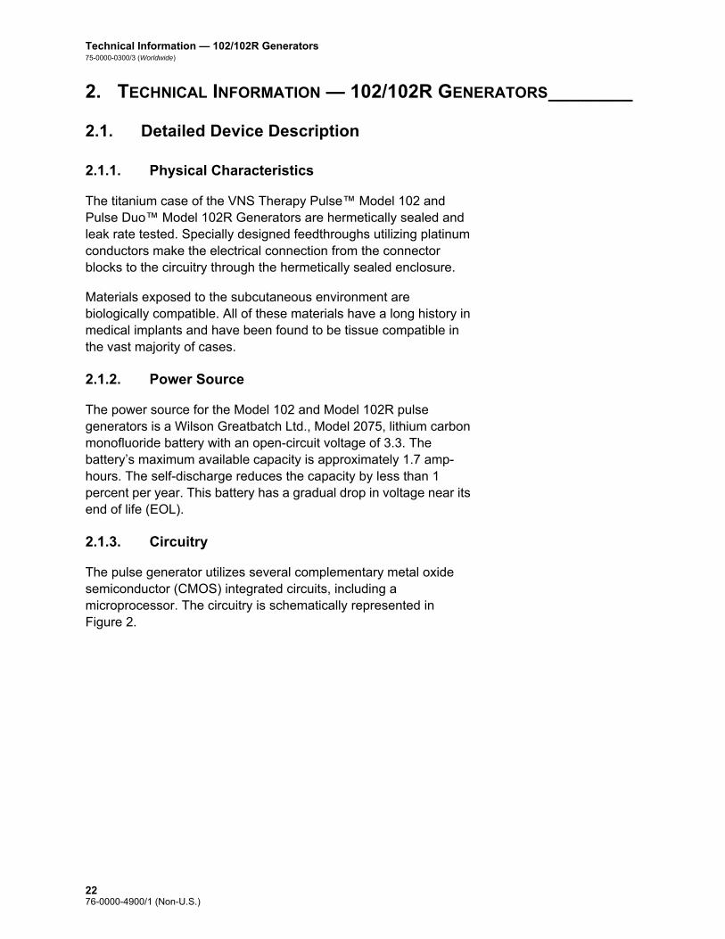
Technical Information — 102/102R Generators75-0000-0300/3 (Worldwide)
2. TECHNICAL INFORMATION — 102/102R GENERATORS________
2.1. Detailed Device Description
2.1.1. Physical Characteristics
The titanium case of the VNS Therapy Pulse™ Model 102 and Pulse Duo™ Model 102R Generators are hermetically sealed and leak rate tested. Specially designed feedthroughs utilizing platinum conductors make the electrical connection from the connector blocks to the circuitry through the hermetically sealed enclosure.
Materials exposed to the subcutaneous environment are biologically compatible. All of these materials have a long history in medical implants and have been found to be tissue compatible in the vast majority of cases.
2.1.2. Power Source
The power source for the Model 102 and Model 102R pulse generators is a Wilson Greatbatch Ltd., Model 2075, lithium carbon monofluoride battery with an open-circuit voltage of 3.3. The battery’s maximum available capacity is approximately 1.7 amp-hours. The self-discharge reduces the capacity by less than 1 percent per year. This battery has a gradual drop in voltage near its end of life (EOL).
2.1.3. Circuitry
The pulse generator utilizes several complementary metal oxide semiconductor (CMOS) integrated circuits, including a microprocessor. The circuitry is schematically represented in Figure 2.
2276-0000-4900/1 (Non-U.S.)

Technical Information—102/102R Generators75-0000-0300/3 (Worldwide)
For descriptive purposes, circuitry of the pulse generator can be divided into the following major functional sections:
Figure 2. Pulse Generator Circuitry
Voltage regulator Regulates the system power supply
Crystal oscillator Provides a timing reference
Logic and control Controls overall pulse generator function; receives and implements programming commands; collects and stores telemetry information
Output Develops and modulates signals delivered to the lead
Antenna Receives programming signals; transmits telemetry information to the programming wand
Reed switch Provides a mechanism to place the pulse generator in Magnet Mode or to inhibit its output
A Battery E Antenna
B Voltage Regulator F Output
C Crystal Oscillator G Reed Switch
D Logic and Control H Lead Electrodes
A
G
HF
C
B D
E
2376-0000-4900/1 (Non-U.S.)

Technical Information — 102/102R Generators75-0000-0300/3 (Worldwide)
2.1.4. Identification
Note: For details on interrogating the pulse generator, see the Programming Software Physician’s Manual.
Note: Serial numbers ≥1000000 = Model 102R and serial numbers <1000000 = Model 102.
The pulse generator can be identified by x-ray and will appear as shown in Figure 3. The serial number and model number of the pulse generator are marked on its titanium case, but do not appear on the x-ray. The serial number and model number can be identified by interrogating the pulse generator with the software and viewing the Device History screen.
Figure 3. X-ray Identification
The x-rays shown in Figure 3 show possible identification code combinations used for Model 102 and 102R pulse generators. The codes are defined as follows:
2.2. VNS Therapy System Compatibility
The VNS Therapy Pulse, Model 102 Generator, and the VNS Therapy Pulse Duo, Model 102R Generator, are compatible with different lead types as follows: Model 102 Generator—Compatible with Cyberonics single-pin
lead
Model 102R Generator—Compatible with Cyberonics dual-pin lead
CYBX Cyberonics
J Model 102 or Model 102R
xx Year (e.g., 10 = 2010)
2476-0000-4900/1 (Non-U.S.)

Technical Information—102/102R Generators75-0000-0300/3 (Worldwide)
Except for leads, both Models 102 and 102R are compatible with the following system components:
2.3. Directions for Use
2.3.1. Specifications and Product Information
The specifications and product information for the VNS Therapy pulse generators are presented in Table 2.
Pulse Generator Model
Component Model 102 102R
Lead dual-pin x
single-pin x
Wand 200 x x
201 x x
Software 250 v.4.6, 6.1, or higher
x x
Tunneler 402 x x
Accessory Pack 502 x x
Magnets 220 x x
2576-0000-4900/1 (Non-U.S.)
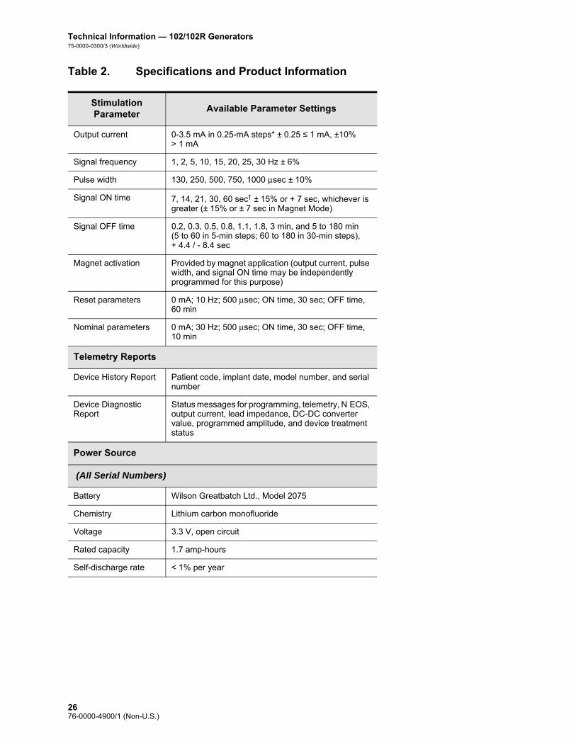
Technical Information — 102/102R Generators75-0000-0300/3 (Worldwide)
Table 2. Specifications and Product Information
Stimulation Parameter
Available Parameter Settings
Output current 0-3.5 mA in 0.25-mA steps* ± 0.25 ≤ 1 mA, ±10% > 1 mA
Signal frequency 1, 2, 5, 10, 15, 20, 25, 30 Hz ± 6%
Pulse width 130, 250, 500, 750, 1000 μsec ± 10%
Signal ON time 7, 14, 21, 30, 60 sec† ± 15% or + 7 sec, whichever is greater (± 15% or ± 7 sec in Magnet Mode)
Signal OFF time 0.2, 0.3, 0.5, 0.8, 1.1, 1.8, 3 min, and 5 to 180 min(5 to 60 in 5-min steps; 60 to 180 in 30-min steps), + 4.4 / - 8.4 sec
Magnet activation Provided by magnet application (output current, pulse width, and signal ON time may be independently programmed for this purpose)
Reset parameters 0 mA; 10 Hz; 500 μsec; ON time, 30 sec; OFF time, 60 min
Nominal parameters 0 mA; 30 Hz; 500 μsec; ON time, 30 sec; OFF time, 10 min
Telemetry Reports
Device History Report Patient code, implant date, model number, and serial number
Device Diagnostic Report
Status messages for programming, telemetry, N EOS, output current, lead impedance, DC-DC converter value, programmed amplitude, and device treatment status
Power Source
(All Serial Numbers)
Battery Wilson Greatbatch Ltd., Model 2075
Chemistry Lithium carbon monofluoride
Voltage 3.3 V, open circuit
Rated capacity 1.7 amp-hours
Self-discharge rate < 1% per year
2676-0000-4900/1 (Non-U.S.)

Technical Information—102/102R Generators75-0000-0300/3 (Worldwide)
Physical Characteristics
Materials
Case Titanium, hermetically sealed
Header Polyurethane—Tecothane™ TT-1075D-M Thermoplastic
Lead connector blocks Stainless steel
Setscrew plug(s) Silicone‡
Measurements (Typical)
Model 102 Model 102R
Lead receptacle(s) 0.126 in (3.2 mm) nominal
0.2 in (5 mm) nominal
Dimensions 2.0 in x 2.0 in x 0.27 in(52 mm x 52 mm x 6.9 mm)
2.0 in x 2.3 in x 0.27 in(52 mm x 58.4 mm x 6.9 mm)
Weight 0.88 oz (25 g) 0.95 oz (27 g)
Connector Retention Strength
With VNS Therapy lead
> 10N
Serial Number Range
Model 102 < 1000000
Model 102R ≥ 1000000
* For output currents ≤ 1 mA, the tolerance is ± 0.25mA. Maximum output is 12.5 ± 2.5 V with the exception of 10 Hz, 7 seconds On Time, in which case the maximum output is 4.4 V and 0.25 mA tolerance. This 0.25 mA tolerance also applies to 15 Hz, 7 seconds On Time, 0.5mA output current.
† For Signal ON time > 7 sec, there is no ramp-down at 15 Hz with 0.5 mA and at 10 Hz with 0.5-1.75 or 2.75 mA. For Signal ON time at 30 sec, actual ON time is 40 sec for 10 Hz with 0.25 mA and 38 sec for 15 Hz with 0.25 mA.
‡ No component of the VNS Therapy System is made with natural rubber latex.
2776-0000-4900/1 (Non-U.S.)

Technical Information — 102/102R Generators75-0000-0300/3 (Worldwide)
2.3.2. Operating Characteristics
2.3.2.1. Communicating with the VNS Therapy System
Note: For a list of compatible computers, see the Programming Software Physician’s Manual.
Note: For proper placement of the programming wand, connection of the wand to the computer, and use of the wand, see the Programming Wand Physician’s Manual.
Note: For proper use of the software, see the Programming Software Physician’s Manual.
Note: For details on viewing the database information, see the Programming Software Physician’s Manual.
A programming wand connected to a compatible computer running the programming software is needed to communicate with the pulse generator.
After the program has been initiated, software screens display prompts and messages to aid in communicating with the pulse generator.
The pulse generator “listens” for a communication signal for a 300-msec period every 6.8 seconds. Communication usually takes between 3 and 10 seconds, but may be prolonged in the presence of electromagnetic interference (EMI). The pulse generator listens for and implements interrogations, parameter programming instructions, requests for Device Diagnostics testing, and Device History inquiries. In response, the pulse generator transmits information on the stimulation parameter settings, changes its parameter settings, responds to requests for Device Diagnostics testing, and provides Device Histories, respectively.
Each time these data are transmitted by the pulse generator, they are saved by the programming software to databases on the storage disk. The pulse generator also transmits a signal for use in evoked potential monitoring.
In addition to the programming software and programming wand combination, a magnet can be used for one-way communication to the pulse generator by activating a reed switch in the electronic circuitry. The magnet can be used to initiate stimulation, temporarily inhibit stimulation, perform Magnet Mode diagnostics, and reset the pulse generator.
2.3.2.2. Stimulation
After the pulse generator has been programmed, the stimulation will repeat in accordance with the programmed ON and OFF cycle until the pulse generator receives communication from the VNS Therapy programming system or until it is activated (epilepsy only) or inhibited with a magnet. Immediately after successful programming, the pulse generator delivers a programmed stimulation that enables patient response to be evaluated. If programming is performed during stimulation, stimulation will be terminated; after programming, stimulation will begin, using the revised settings.
2876-0000-4900/1 (Non-U.S.)

Technical Information—102/102R Generators75-0000-0300/3 (Worldwide)
The pulse generator operation described in the preceding paragraph is done in Normal Mode. A Magnet Mode stimulation is a single stimulation initiated by applying or passing the magnet over the pulse generator for at least 1 second and then immediately removing it from the area over the pulse generator. Stimulation is delivered after the magnet is removed. The Magnet Mode uses the same frequency as the Normal Mode, but the output current, pulse width, and signal ON time are independently programmable. The Directions for Use are equivalent for epilepsy and depression, with the following exceptions: For patients with depression, the Magnet Mode output current
should always be programmed at 0 mA, the setting at which the pulse generator is shipped from Cyberonics.
Use of the Magnet Mode is limited to patients with epilepsy. Patients with epilepsy or their caregivers pass the magnet over the implanted pulse generator to activate on-demand delivery of a single train of vagus nerve stimulation and help abort or diminish a seizure.
Magnet Mode is not used for patients with depression.
An interrogation is made to determine the present settings of the stimulation parameters. If interrogation is made during stimulation, completion of stimulation will be delayed until the interrogation is finished.
A graphic representation of stimulation (Figure 4) depicts the relationship of the stimulation programmable parameters. The programmable parameters are independently variable, offering multiple setting combinations from which the physician may select optimal stimulation for the patient. Figure 4 shows that the output pulse can be varied both by amplitude (output current) and duration (pulse width). The number of output pulses delivered per second determines the frequency.
Note: The various parameter settings for stimulation are listed in “Specifications and Product Information”.
Note: See “Effects of programmed settings on pulse generator projected lifetime”.
The percentage of time the pulse generator is stimulating is called a “duty cycle.” A duty cycle is calculated by dividing the stimulation time (programmed ON time plus 2 seconds of ramp-up time and 2 seconds of ramp-down time) by the sum of the ON and OFF times.
When selecting a combination of parameter settings that will deliver optimal stimulation, the physician should also consider that some combinations will decrease battery life faster than others.
2976-0000-4900/1 (Non-U.S.)

Technical Information — 102/102R Generators75-0000-0300/3 (Worldwide)
Figure 4. Stimulation (Frequencies < 10 Hz do not ramp)
2.3.2.2.1. Initiating stimulation with the magnet
There are four possible uses of the magnet: Epilepsy —To provide on-demand stimulation as an attempt to
abort or de-intensify an oncoming seizure
To temporarily inhibit stimulation
To reset the pulse generator (in combination with the programming wand)
Caution: Possible nerve damage with ON time > OFF time— Excessive stimulation has resulted in degenerative nerve damage in laboratory animals. One component of excessive stimulation is when ON time exceeds OFF time, which can be produced by continuous or frequent magnet activation (> 8hours). Cyberonics recommends that stimulation at these combinations of ranges be avoided.
Epilepsy —To test daily the functioning of the pulse generator, Cyberonics recommends that patients be instructed to use the magnet to activate stimulation. During an aura or at the start of a seizure, magnet activation may be initiated by the patient, a companion, or the physician by applying or passing the magnet over the pulse generator to activate a reed switch in the pulse generator’s electronic circuitry. This action changes the pulse generator from Normal Mode to Magnet Mode.
Two identical magnets (see Figure 5), each providing a minimum of 50 gauss at 1 inch, are supplied by Cyberonics. A Cyberonics watch-style magnet attaches to a wristband in the same manner as a wristwatch, and a Cyberonics pager-style magnet attaches to a belt in the same manner as a pager with a quick-release mechanism.
A Stimulation Time E Output Current
B Ramp Up (2 sec.) F 1/Signal Frequency
C On Time G Pulse Width
D Ramp Down (2 sec.) H Off Time
AB C D
E
FG
H
3076-0000-4900/1 (Non-U.S.)

Technical Information—102/102R Generators75-0000-0300/3 (Worldwide)
Figure 5. Magnet Styles
Epilepsy —The proper orientation and motion for initiating magnet activation is shown in Figure 6. The magnet is shown without the belt clip or wristband to illustrate the proper orientation of the magnet to the pulse generator.
Caution: Label side of magnet should face the pulse generator while activating or stopping stimulation.
Figure 6. Initiating Magnet Activation
All magnets may lose their effectiveness over time. Avoid dropping the Cyberonics magnets or storing them near other magnets.
Epilepsy —To initiate stimulation, apply or pass the magnet over the pulse generator for at least 1 second, and then immediately remove it from the area over the pulse generator. Removal of the magnet causes the pulse generator to operate in Magnet Mode, delivering a single stimulation with the programmed magnet pulse width, magnet current, and magnet signal ON time settings. The frequency is the programmed value for Normal Mode. Any Normal Mode programmed stimulation will always be overridden by a Magnet Mode, even if the Magnet Mode output current is set to 0 mA. If Magnet Mode stimulation is not desired, the Magnet Mode output current may be programmed to 0 mA. Magnet use does not restart the normal OFF time. Therefore, depending on the timing of
A Cyberonics Magnet (watch-style)
B Cyberonics Magnet (pager-style)
A B
Model 102 Model 102R
3176-0000-4900/1 (Non-U.S.)

Technical Information — 102/102R Generators75-0000-0300/3 (Worldwide)
the magnet use, the patient could receive a second stimulation quickly after magnet activation.
Epilepsy —Cyberonics recommends that tests of the magnet output be performed while the patient is still in the physician’s office to ensure tolerability of the magnet output.
2.3.2.2.2. Inhibiting pulse generator output with a magnet
Caution: If stimulation becomes painful, the patient should be instructed to stop the stimulation with the magnet.
Application of the magnet during stimulation will inhibit the output. In addition, holding the magnet in place for at least 65 seconds will prevent the initiation of a Magnet Mode stimulation and will terminate any ongoing Normal Mode stimulation. After the magnet is removed, Normal Mode operation will resume with stimulation when one complete OFF time has elapsed. In the unlikely event of continuous stimulation or other malfunction, the patient must be advised to apply the magnet, secure it in place, and immediately notify his or her physician.
2.3.2.2.3. Resetting the microprocessor using the magnet and programming wand
Caution: When the pulse generator is reset, all device history information is lost, and the reset parameters (0 mA, 10 Hz; 500 μsec; ON time, 30 seconds; OFF time, 60 minutes) are internally programmed. Resetting the pulse generator turns the device off (output current = 0 mA). After a successful reset, the pulse generator patient code must be re-entered, and the pulse generator reprogrammed to the desired parameters.
The VNS Therapy System allows the pulse generator microprocessor to be reset in the event of a malfunction. Resetting will be necessary only in the rare case of microprocessor memory malfunction, which might be caused by conditions described in the “Environmental Hazards” section in the Introduction to the VNS Therapy System chapter. Microprocessor reset is indicated when communication with the pulse generator becomes impossible. (For suggestions in solving communication difficulties, see “Troubleshooting” in the programming wand physician’s manual and “Precautions” and “Troubleshooting” in the Programming Software Physician’s Manual.)
For instructions on resetting the microprocessor, refer to the Programming Wand Physician’s Manual. It is recommended, except in cases of a medical emergency, that the physician consults a Cyberonics technical representative before resetting is performed.
3276-0000-4900/1 (Non-U.S.)

Technical Information—102/102R Generators75-0000-0300/3 (Worldwide)
2.3.2.2.4. Effects of the daily reset of the internal clock
Note: The time that the clock restarts each day corresponds with the time of day the most recent programming event occurred. Holding the magnet over the generator for an extended period of time will put all timekeeping functions on hold and will delay the time that the internal clock rolls over each day.
Note: For a complete list of side effects, see “Adverse Events” in the indication specific information chapters.
The Model 102 and 102R pulse generators contain an internal clock that rolls over (i.e., restarts) every 24 hours. This daily rollover of the internal clock is a normal device function. Every time the clock restarts, a stimulation cycle beginning with the programmed ON time is delivered. Patients may notice a shorter OFF time between the last stimulation cycle just prior to the clock restart and the first stimulation cycle after the clock restart.
Some patients may be more sensitive to this shorter OFF time and may exhibit common stimulation related side effects (e.g. coughing, voice changes). These side effects will only occur once a day at the time of the daily clock restart. In the rare reported instances in which side effects occurred with the daily clock restart, it was noted that the most common programmed duty cycle was 30 seconds ON and 3 minutes OFF along with a high output current (> 2 mA).
As with any normal side effect, adjusting settings for tolerability (i.e., decreasing pulse width, signal frequency, and/or output current) has been shown to be successful in resolving stimulation related side effects associated with the 24-hour rollover event. However, since this 24-hour rollover event is directly related to the programmed ON and OFF times, adjusting the duty cycle may be a better option. Optimizing the patient's benefit from therapy should be considered when making the decision as to which parameter should be adjusted. For example, if the patient is responding well clinically at a particular output current, adjusting a different parameter or duty cycle may be considered. Table 3 shows several ON and OFF time combinations that may be better options when trying to resolve stimulation related side effects associated with the daily clock restart.
3376-0000-4900/1 (Non-U.S.)

Technical Information — 102/102R Generators75-0000-0300/3 (Worldwide)
Note: For a comprehensive list of duty cycle settings, see Table 5.
Table 3. ON/OFF Time — Options for Optimizing Therapy for Patients Affected by the Internal Clock Cycle
2.3.2.3. Device history
The Device History consists of the pulse generator serial number, model number, the patient code (usually three initials), implantation date, and other information pertinent to diagnostic and programming events. Use the software to access and view Device History information.
2.3.2.4. Device diagnostics
Note: For details on available diagnostic tests, see the Programming Software Physician’s Manual.
Information from pulse generator Diagnostics (Pre-Implant Test) aids the physician in determining if the pulse generator is operating properly before it is implanted, if the pulse generator output current is being delivered at the programmed value, if lead impedance is within an acceptable range, and in which mode the pulse generator is operating.
2.3.2.4.1. Reasons for high lead impedance readings
The System Diagnostics (Lead Test) is the most appropriate of the device diagnostic tests to evaluate lead impedance for the VNS Therapy System. The System Diagnostics (Lead Test) is performed at 1 mA, 500 μsec. Use Table 4 to find the DC-DC Converter Code
ON Time (sec) OFF Time (min)
7 0.3
14 0.5
21 0.5
7 0.8
14 1.1
30 1.1
60 1.1
30 1.8
7 3.0
14 3.0
60 5.0
14 10.0
3476-0000-4900/1 (Non-U.S.)

Technical Information—102/102R Generators75-0000-0300/3 (Worldwide)
displayed by the System Diagnostics (Lead Test) screen to determine an estimate of lead impedance in kOhms.
The use of Table 4 with the DC-DC Converter Code from diagnostic screens other than the System Diagnostics (Lead Test) and Generator Diagnostics (Pre-Implant Test) is not appropriate, unless the pulse generator output parameters are the values indicated in the tables. High lead impedance is defined as any DC-DC Converter Code greater than or equal to four with 1 mA of diagnostic current.
Caution: Possible causes of high lead impedance readings are thought to include lead discontinuity, lead disconnection from the pulse generator, fibrosis between the nerve and the electrode, electrode detachment from the nerve, or in rare instances, a defective pulse generator or high battery impedance approaching end of service (EOS).
Table 4. DC-DC Converter Codes and Lead Impedance (Models 102 and 102R)
Note: For additional instructions on performing the System Diagnostics (Lead Test), see the Programming Software Physician’s Manual.
High lead impedance, in the absence of other device-related complications, is not an indication of a lead or pulse generator malfunction. High lead impedance in combination with the patient’s failure to feel even the maximum output stimulus may indicate a lead wire fracture or other type of electrical discontinuity in the lead. Patients experiencing high lead impedance, no sensation of maximum output stimulation, and an increase in seizures/depressive symptoms should be further evaluated for possible lead replacement.
2.3.2.4.2. Short-circuit conditions within the lead
In rare instances, a short-circuit condition within the lead (e.g., direct contact between lead wires) may result in a DC-DC Converter Code of “0” on the System Diagnostics (Lead Test). A significant
DC-DC
Converter Code1
Estimated Lead Impedance2
1 mA, 500 μsec
0 ≤ 1.7 kOhms
1 1.8-2.8 kOhms
2 2.9-4.0 kOhms
3 4.1-5.2 kOhms
4 5.3-6.5 kOhms
5 6.6-7.7 kOhms
6 7.8-8.9 kOhms
7 ≥ 9 kOhms
1 DC-DC Converter Codes are displayed during System Diagnostics (Lead Test).2 Tolerance is ± 10 percent.
3576-0000-4900/1 (Non-U.S.)

Technical Information — 102/102R Generators75-0000-0300/3 (Worldwide)
decrease in DC-DC Converter Code value on the System Diagnostics (e.g., “3” to “1”) from prior System Diagnostics may also indicate a lead problem. Patients affected by this event may experience conditions such as an increase in seizures/depressive symptoms, painful stimulation, a feeling of erratic stimulation or no stimulation, or a feeling of stimulation in an atypical anatomical location. In the absence of these adverse events or device-related complications, a DC-DC Converter Code of “0” or decrease in DC-DC Converter code value likely does not indicate a lead malfunction.
2.3.2.4.3. Lead problem troubleshooting
Either evoked potential monitoring equipment or an oscilloscope can be used to analyze the stimulus waveform from the neck for verification of an electrical discontinuity. A differentiated waveform with narrowed pulses or no wave form at all can confirm a discontinuity. Figure 7 shows simulated waveforms expected from skin electrodes for a lead that is intact and for a lead that has a fracture in one or both wires. In addition to these approaches, lead discontinuities can sometimes be identified in x-rays of the implant site.
Figure 7. Typical Waveforms Obtained from Skin Electrodes
2.3.2.5. Delivery of programmed output current
If the diagnostic tests indicate the output current is LIMIT, the pulse generator may not deliver the programmed output current. Reasons for failure to deliver the programmed output current include a high output current, high lead impedance, and low battery voltage. Figure 8 demonstrates the relationship of lead impedance to maximum deliverable output current.
If the pulse generator fails to deliver the programmed output current, the physician can reprogram to a lower output current and attempt to compensate for a decrease in delivered energy by
A Intact Lead
B One Broken Lead Wire
C Two Broken Lead Wires or No Output
A B C
3676-0000-4900/1 (Non-U.S.)

Technical Information—102/102R Generators75-0000-0300/3 (Worldwide)
widening the pulse width. For example, if the output current is at LIMIT for a pulse generator programmed at 2.5 mA, 30 Hz, 500 μsec with 30 seconds ON time, then the parameters may be changed by lowering the output current to 2 mA and widening the pulse width to 750 μsec.
Figure 8. Relationship of Lead Impedance to Maximum Deliverable Output Current
2.3.2.6. Charge delivered per pulse
Caution: Do not use frequencies of 5 Hz or below for long-term stimulation. Because these frequencies generate an electromagnetic trigger signal, their use results in excessive battery depletion of the implanted pulse generator and, therefore, should be used for short periods of time only.
The charge delivered per pulse is the parameter most important in evaluating stimulation output. It is defined as a microcoulomb (μC), which is the product of current and time—that is, the output current (mA) multiplied by the pulse width (msec). Figure 9 shows the relationship of programmed output current (μC) to lead impedance for an output current of 0 to 3.5 mA.
Lead Test Diagnostic DC-DC Code @ 1mA
The maximum output current, according to Ohm's Law: Max. Output Current =
Output Voltage (12V) / Lead Impedance
Lead Impedance (ohms)
Out
put C
urre
nt
3776-0000-4900/1 (Non-U.S.)

Technical Information — 102/102R Generators75-0000-0300/3 (Worldwide)
Figure 9. Relationship of Programmed Output Current to Lead Impedance
2.3.2.7. Effects of programmed settings on pulse generator projected lifetime
Note: More frequent follow-up may be required as the pulse generator approaches the near end of service (N EOS) indicator. The time from N EOS to EOS is highly dependent on the programmed parameters and the lead impedance. See Table 6 and Table 7.
The choice of settings for output parameters affects pulse generator battery life. Generally, a high duty cycle will deplete the battery over a shorter period of time than a low duty cycle will. Table 5 shows duty cycles for typical ON time and OFF time settings (except for frequency settings < 10 Hz). Nominal values of 2 second ramp-up time and 2 second ramp-down time are used for the duty cycle calculations, although actual ramp-up and ramp-down times may vary at lower frequencies or output currents. As depicted in the graphic representation of stimulation in Figure 4, neither of the ramp times is considered part of the programmed ON time; however, they are included in calculations for determining the percentage of stimulation time (duty cycle) and predicting battery life.
Lead Impedance (k ohms)
Del
iver
ed O
utpu
t (m
illia
mps
or
mic
roco
ulom
bs a
t 100
0 µs
ec)
(1 microcoulomb = 1 mA for 1000 µsec pulse width or 2
mA for 500 µsec pulse width)
3876-0000-4900/1 (Non-U.S.)

Technical Information—102/102R Generators75-0000-0300/3 (Worldwide)
Caution: Possible nerve damage with ON time > OFF time— Excessive stimulation has resulted in degenerative nerve damage in laboratory animals. One component of excessive stimulation is when ON time exceeds OFF time, which can be produced by continuous or frequent magnet activation (> 8 hours). Cyberonics recommends that stimulation at these combinations of ranges be avoided.
Table 5. Duty Cycles for Various ON and OFF Time Settings
For Models 102 and 102R, the approximate battery lifetime predicted at programmed settings of 20 Hz with a 500 μsec pulse width and 2 mA output current, a lead impedance of 4 kOhms, and a duty cycle of 10 percent is 8.4 years (100.8 months). These pulse generators have an N EOS that provides a warning period prior to EOS.
Table 6 and Table 7 provide estimated battery lifetimes under a variety of stimulation conditions, including lead impedance. Because of the number of possible parameter combinations, it is impractical to provide the projected life for all possible combinations. The tables should not be used to predict battery end of service (EOS), but they give some indication of the effect of various parameter changes on battery life and can be used to assist in the selection of parameter settings. They also indicate that battery life can be maximized at low duty cycles and low frequencies (10 to 20 Hz) for stimulation. Once N EOS is detected, the pulse generator should be replaced as soon as possible.
OFF Time (min)
0.2 0.3 0.5 0.8 1.1 1.8 3 5 10
ON Time (sec)
Duty Cycles* (% ON Time)
7 58 44 30 20 15 10 6 4 2
14 69 56 41 29 23 15 9 6 3
21 76 64 49 36 29 19 12 8 4
30 81 71 57 44 35 25 16 10 5
60 89 82 71 59 51 38 27 18 10
* A duty cycle is calculated by dividing stimulation time (programmed ON time plus 2 seconds of ramp-up time and 2 seconds of ramp-down time) by the sum of the ON time and the OFF time.
* The duty cycles in gray are not recommended as they represent parameter combinations with ON Time > OFF Time.
3976-0000-4900/1 (Non-U.S.)

Technical Information — 102/102R Generators75-0000-0300/3 (Worldwide)
Table 6. Estimated Battery Life - Nominal Longevity Estimates from Beginning of Life (BOL) to End of Service (EOS)
Output Current
(mA)
Frequency (Hz)
Pulse Width (μsec)
DC-DC Converter
Code
Nominal Estimated Battery Life (Years)
10% Duty Cycle Life
33% Duty Cycle Life
50% Duty Cycle Life
1 10 130 2 15.3 11.3 9.5
1 10 130 3 15.1 11.1 9.2
1 10 130 5 14.8 10.5 8.7
1 10 130 7 14.4 9.8 8.0
1 10 500 2 14.2 9.6 7.7
1 10 500 3 13.8 8.9 7.1
1 10 500 5 13.0 7.9 6.1
1 10 500 7 12.4 7.3 5.6
1 10 1000 2 12.8 7.6 5.9
1 10 1000 3 12.2 6.9 5.3
1 10 1000 5 10.9 5.7 4.2
1 10 1000 7 10.3 5.2 3.8
1 20 130 2 14.2 9.5 7.6
1 20 130 3 13.8 9.0 7.2
1 20 130 5 13.4 8.5 6.7
1 20 130 7 12.7 7.6 5.9
1 20 500 2 12.3 7.1 5.4
1 20 500 3 11.7 6.5 4.9
1 20 500 5 10.6 5.5 4.0
1 20 500 7 10.0 4.9 3.6
1 20 1000 2 10.3 5.2 3.8
1 20 1000 3 9.6 4.6 3.3
1 20 1000 5 8.2 3.6 2.6
1 20 1000 7 7.5 3.2 2.3
1 30 130 2 13.1 8.1 6.3
1 30 130 3 12.7 7.6 5.9
1 30 130 5 12.2 7.0 5.3
4076-0000-4900/1 (Non-U.S.)

Technical Information—102/102R Generators75-0000-0300/3 (Worldwide)
1 30 130 7 11.4 6.2 4.6
1 30 500 2 10.9 5.7 4.2
1 30 500 3 10.2 5.1 3.7
1 30 500 5 9.0 4.2 3.0
1 30 500 7 8.3 3.7 2.6
1 30 1000 2 8.7 3.9 2.8
1 30 1000 3 7.9 3.5 2.4
1 30 1000 5 6.6 2.7 1.8
1 30 1000 7 5.9 2.3 1.6
1.5 10 130 2 14.7 10.3 8.4
1.5 10 130 3 14.4 9.8 7.9
1.5 10 130 5 13.7 8.8 7.0
1.5 10 130 7 13.8 8.9 7.1
1.5 10 500 2 12.4 7.3 5.6
1.5 10 500 3 12.0 6.7 5.1
1.5 10 500 5 10.9 5.7 4.3
1.5 10 500 7 11.2 6.0 4.5
1.5 10 1000 2 10.3 5.2 3.8
1.5 10 1000 3 9.6 4.6 3.3
1.5 10 1000 5 8.4 3.8 2.7
1.5 10 1000 7 8.9 4.1 2.9
1.5 20 130 2 13.1 8.0 6.2
1.5 20 130 3 12.6 7.5 5.8
1.5 20 130 5 11.8 6.5 4.9
1.5 20 130 7 11.8 6.6 5.0
1.5 20 500 2 10.0 5.0 3.6
1.5 20 500 3 9.4 4.5 3.2
1.5 20 500 5 8.2 3.7 2.6
1.5 20 500 7 8.6 3.9 2.8
1.5 20 1000 2 7.5 3.2 2.2
Output Current
(mA)
Frequency (Hz)
Pulse Width (μsec)
DC-DC Converter
Code
Nominal Estimated Battery Life (Years)
10% Duty Cycle Life
33% Duty Cycle Life
50% Duty Cycle Life
4176-0000-4900/1 (Non-U.S.)

Technical Information — 102/102R Generators75-0000-0300/3 (Worldwide)
1.5 20 1000 3 6.8 2.8 2.0
1.5 20 1000 5 5.7 2.2 1.5
1.5 20 1000 7 6.2 2.4 1.7
1.5 30 130 2 11.8 6.5 4.9
1.5 30 130 3 11.3 6.1 4.5
1.5 30 130 5 10.3 5.2 3.8
1.5 30 130 7 10.4 5.3 3.9
1.5 30 500 2 8.4 3.8 2.7
1.5 30 500 3 7.7 3.3 2.4
1.5 30 500 5 6.6 2.7 1.9
1.5 30 500 7 7.0 2.9 2.0
1.5 30 1000 2 5.9 2.3 1.6
1.5 30 1000 3 5.3 2.0 1.4
1.5 30 1000 5 4.3 1.6 1.1
1.5 30 1000 7 4.7 1.8 1.2
2 10 130 2 14.1 9.4 7.5
2 10 130 3 13.5 8.5 6.7
2 10 130 5 13.5 8.5 6.7
2 10 130 7 13.7 8.8 7.0
2 10 500 2 11.2 6.0 4.4
2 10 500 3 10.1 5.0 3.6
2 10 500 5 10.5 5.4 3.9
2 10 500 7 11.1 5.9 4.3
2 10 1000 2 8.4 3.8 2.7
2 10 1000 3 7.4 3.1 2.2
2 10 1000 5 7.9 3.5 2.4
2 10 1000 7 8.6 3.9 2.8
2 20 130 2 12.2 7.0 5.3
2 20 130 3 11.3 6.0 4.5
2 20 130 5 11.4 6.2 4.6
Output Current
(mA)
Frequency (Hz)
Pulse Width (μsec)
DC-DC Converter
Code
Nominal Estimated Battery Life (Years)
10% Duty Cycle Life
33% Duty Cycle Life
50% Duty Cycle Life
4276-0000-4900/1 (Non-U.S.)

Technical Information—102/102R Generators75-0000-0300/3 (Worldwide)
2 20 130 7 11.7 6.5 4.9
2 20 500 2 8.4 3.8 2.7
2 20 500 3 7.3 3.1 2.2
2 20 500 5 7.8 3.4 2.4
2 20 500 7 8.4 3.8 2.7
2 20 1000 2 5.5 2.1 1.5
2 20 1000 3 4.8 1.8 1.2
2 20 1000 5 5.3 2.0 1.4
2 20 1000 7 5.9 2.3 1.6
2 30 130 2 10.8 5.6 4.1
2 30 130 3 9.7 4.7 3.4
2 30 130 5 9.9 4.9 3.5
2 30 130 7 10.2 5.1 3.8
2 30 500 2 6.8 2.8 1.9
2 30 500 3 5.7 2.2 1.5
2 30 500 5 6.2 2.5 1.7
2 30 500 7 6.8 2.8 1.9
2 30 1000 2 4.0 1.4 1.0
2 30 1000 3 3.6 1.3 0.8
2 30 1000 5 4.0 1.4 1.0
2 30 1000 7 4.6 1.7 1.1
3.5 10 130 2 12.6 7.5 5.7
3.5 10 130 3 12.9 7.8 6.0
3.5 10 130 5 13.3 8.3 6.5
3.5 10 130 7 13.5 8.6 6.8
3.5 10 500 2 8.6 3.9 2.8
3.5 10 500 3 9.2 4.4 3.1
3.5 10 500 5 10.1 5.0 3.7
3.5 10 500 7 10.8 5.6 4.1
3.5 10 1000 2 5.8 2.3 1.6
Output Current
(mA)
Frequency (Hz)
Pulse Width (μsec)
DC-DC Converter
Code
Nominal Estimated Battery Life (Years)
10% Duty Cycle Life
33% Duty Cycle Life
50% Duty Cycle Life
4376-0000-4900/1 (Non-U.S.)

Technical Information — 102/102R Generators75-0000-0300/3 (Worldwide)
3.5 10 1000 3 6.5 2.6 1.8
3.5 10 1000 5 7.5 3.2 2.3
3.5 10 1000 7 8.3 3.7 2.6
3.5 20 130 2 10.2 5.1 3.8
3.5 20 130 3 10.6 5.5 4.0
3.5 20 130 5 11.1 5.9 4.4
3.5 20 130 7 11.5 6.3 4.7
3.5 20 500 2 5.9 2.3 1.6
3.5 20 500 3 6.5 2.6 1.8
3.5 20 500 5 7.4 3.1 2.2
3.5 20 500 7 8.1 3.5 2.5
3.5 20 1000 2 3.6 1.3 0.9
3.5 20 1000 3 4.1 1.5 1.0
3.5 20 1000 5 5.0 1.9 1.3
3.5 20 1000 7 5.6 2.2 1.5
3.5 30 130 2 8.6 3.9 2.8
3.5 30 130 3 9.0 4.2 3.0
3.5 30 130 5 9.6 4.6 3.3
3.5 30 130 7 10.0 4.9 3.6
3.5 30 500 2 4.5 1.7 1.1
3.5 30 500 3 5.0 1.9 1.3
3.5 30 500 5 5.8 2.3 1.6
3.5 30 500 7 6.5 2.6 1.8
3.5 30 1000 2 2.7 0.9 0.6
3.5 30 1000 3 3.0 1.0 0.7
3.5 30 1000 5 3.7 1.3 0.9
3.5 30 1000 7 4.3 1.6 1.1
Output Current
(mA)
Frequency (Hz)
Pulse Width (μsec)
DC-DC Converter
Code
Nominal Estimated Battery Life (Years)
10% Duty Cycle Life
33% Duty Cycle Life
50% Duty Cycle Life
4476-0000-4900/1 (Non-U.S.)

Technical Information—102/102R Generators75-0000-0300/3 (Worldwide)
Table 7. Estimated Battery Life - Worst Case Longevity Estimates from Beginning of Life (BOL) to Near End of Service (N EOS)
Output Current
(mA)
Frequency (Hz)
Pulse Width (μsec)
DC-DC Converter
Code
Worst Case Estimated Battery Life (Years)
10% Duty Cycle Life
33% Duty Cycle Life
50% Duty Cycle Life
1 10 130 2 9.3 7.1 6.0
1 10 130 3 9.3 7.2 6.1
1 10 130 5 8.8 6.2 5.1
1 10 130 7 8.8 6.2 5.0
1 10 500 2 9.1 6.8 5.7
1 10 500 3 8.9 6.4 5.2
1 10 500 5 8.2 5.3 4.2
1 10 500 7 8.0 5.0 3.9
1 10 1000 2 8.3 5.4 4.3
1 10 1000 3 8.0 5.1 4.0
1 10 1000 5 7.2 4.1 3.1
1 10 1000 7 6.8 3.7 2.8
1 20 130 2 9.1 6.7 5.6
1 20 130 3 8.9 6.4 5.3
1 20 130 5 8.6 5.9 4.8
1 20 130 7 8.2 5.3 4.2
1 20 500 2 8.2 5.2 4.2
1 20 500 3 7.8 4.8 3.7
1 20 500 5 6.9 3.8 2.8
1 20 500 7 6.7 3.6 2.7
1 20 1000 2 6.9 3.7 2.8
1 20 1000 3 6.6 3.5 2.6
1 20 1000 5 5.7 2.8 2.0
1 20 1000 7 5.2 2.4 1.7
1 30 130 2 8.6 5.9 4.7
1 30 130 3 8.4 5.6 4.4
1 30 130 5 8.0 5.0 3.9
4576-0000-4900/1 (Non-U.S.)
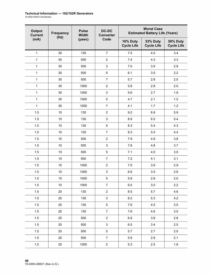
Technical Information — 102/102R Generators75-0000-0300/3 (Worldwide)
1 30 130 7 7.5 4.5 3.4
1 30 500 2 7.4 4.3 3.3
1 30 500 3 7.0 3.9 2.9
1 30 500 5 6.1 3.0 2.2
1 30 500 7 5.7 2.8 2.0
1 30 1000 2 5.8 2.8 2.0
1 30 1000 3 5.6 2.7 1.9
1 30 1000 5 4.7 2.1 1.5
1 30 1000 7 4.1 1.7 1.2
1.5 10 130 2 9.2 6.9 5.9
1.5 10 130 3 8.9 6.5 5.4
1.5 10 130 5 8.3 5.4 4.3
1.5 10 130 7 8.3 5.5 4.4
1.5 10 500 2 7.9 4.9 3.8
1.5 10 500 3 7.8 4.8 3.7
1.5 10 500 5 7.1 4.0 3.0
1.5 10 500 7 7.2 4.1 3.1
1.5 10 1000 2 7.0 3.9 2.9
1.5 10 1000 3 6.6 3.5 2.6
1.5 10 1000 5 5.8 2.8 2.0
1.5 10 1000 7 6.0 3.0 2.2
1.5 20 130 2 8.5 5.7 4.6
1.5 20 130 3 8.2 5.3 4.2
1.5 20 130 5 7.6 4.5 3.5
1.5 20 130 7 7.6 4.6 3.5
1.5 20 500 2 6.9 3.8 2.8
1.5 20 500 3 6.5 3.4 2.5
1.5 20 500 5 5.7 2.7 2.0
1.5 20 500 7 5.9 2.9 2.1
1.5 20 1000 2 5.3 2.5 1.8
Output Current
(mA)
Frequency (Hz)
Pulse Width (μsec)
DC-DC Converter
Code
Worst Case Estimated Battery Life (Years)
10% Duty Cycle Life
33% Duty Cycle Life
50% Duty Cycle Life
4676-0000-4900/1 (Non-U.S.)

Technical Information—102/102R Generators75-0000-0300/3 (Worldwide)
1.5 20 1000 3 4.9 2.2 1.5
1.5 20 1000 5 4.2 1.7 1.2
1.5 20 1000 7 4.5 1.9 1.3
1.5 30 130 2 7.8 4.8 3.8
1.5 30 130 3 7.5 4.5 3.4
1.5 30 130 5 6.9 3.7 2.8
1.5 30 130 7 6.9 3.8 2.8
1.5 30 500 2 5.9 2.9 2.1
1.5 30 500 3 5.5 2.6 1.9
1.5 30 500 5 4.8 2.1 1.5
1.5 30 500 7 5.0 2.2 1.6
1.5 30 1000 2 4.3 1.8 1.3
1.5 30 1000 3 3.9 1.6 1.1
1.5 30 1000 5 3.3 1.2 0.8
1.5 30 1000 7 3.5 1.4 1.0
2 10 130 2 8.8 6.3 5.2
2 10 130 3 8.0 5.0 4.0
2 10 130 5 8.2 5.3 4.2
2 10 130 7 8.3 5.5 4.4
2 10 500 2 7.4 4.3 3.3
2 10 500 3 6.6 3.5 2.6
2 10 500 5 6.9 3.7 2.8
2 10 500 7 7.2 4.0 3.1
2 10 1000 2 5.6 2.6 1.9
2 10 1000 3 5.1 2.3 1.7
2 10 1000 5 5.5 2.6 1.9
2 10 1000 7 5.9 2.9 2.1
2 20 130 2 8.0 5.0 3.9
2 20 130 3 7.3 4.2 3.2
2 20 130 5 7.4 4.3 3.3
Output Current
(mA)
Frequency (Hz)
Pulse Width (μsec)
DC-DC Converter
Code
Worst Case Estimated Battery Life (Years)
10% Duty Cycle Life
33% Duty Cycle Life
50% Duty Cycle Life
4776-0000-4900/1 (Non-U.S.)

Technical Information — 102/102R Generators75-0000-0300/3 (Worldwide)
2 20 130 7 7.6 4.5 3.4
2 20 500 2 5.8 2.8 2.0
2 20 500 3 5.2 2.3 1.7
2 20 500 5 5.4 2.5 1.8
2 20 500 7 5.8 2.8 2.0
2 20 1000 2 3.7 1.4 1.0
2 20 1000 3 3.6 1.4 1.0
2 20 1000 5 3.9 1.6 1.1
2 20 1000 7 4.3 1.8 1.3
2 30 130 2 7.3 4.1 3.1
2 30 130 3 6.5 3.4 2.5
2 30 130 5 6.7 3.5 2.6
2 30 130 7 6.8 3.7 2.8
2 30 500 2 4.7 2.1 1.5
2 30 500 3 4.2 1.7 1.2
2 30 500 5 4.5 1.9 1.3
2 30 500 7 4.9 2.1 1.5
2 30 1000 2 2.9 1.0 0.7
2 30 1000 3 2.7 1.0 0.7
2 30 1000 5 3.1 1.1 0.8
2 30 1000 7 3.4 1.3 0.9
3.5 10 130 2 7.9 4.9 3.8
3.5 10 130 3 8.0 5.1 4.0
3.5 10 130 5 8.2 5.3 4.2
3.5 10 130 7 8.3 5.5 4.4
3.5 10 500 2 5.9 2.9 2.1
3.5 10 500 3 6.2 3.1 2.3
3.5 10 500 5 6.7 3.6 2.7
3.5 10 500 7 7.0 3.9 2.9
3.5 10 1000 2 4.2 1.8 1.2
Output Current
(mA)
Frequency (Hz)
Pulse Width (μsec)
DC-DC Converter
Code
Worst Case Estimated Battery Life (Years)
10% Duty Cycle Life
33% Duty Cycle Life
50% Duty Cycle Life
4876-0000-4900/1 (Non-U.S.)

Technical Information—102/102R Generators75-0000-0300/3 (Worldwide)
3.5 10 1000 3 4.6 2.0 1.4
3.5 10 1000 5 5.2 2.4 1.7
3.5 10 1000 7 5.7 2.7 2.0
3.5 20 130 2 6.8 3.7 2.7
3.5 20 130 3 7.0 3.9 2.9
3.5 20 130 5 7.3 4.2 3.2
3.5 20 130 7 7.4 4.4 3.3
3.5 20 500 2 4.3 1.8 1.3
3.5 20 500 3 4.7 2.0 1.4
3.5 20 500 5 5.2 2.4 1.7
3.5 20 500 7 5.6 2.7 1.9
3.5 20 1000 2 2.8 1.0 0.7
3.5 20 1000 3 3.1 1.2 0.8
3.5 20 1000 5 3.7 1.5 1.0
3.5 20 1000 7 4.1 1.7 1.2
3.5 30 130 2 6.0 2.9 2.1
3.5 30 130 3 6.2 3.1 2.3
3.5 30 130 5 6.5 3.4 2.5
3.5 30 130 7 6.7 3.6 2.7
3.5 30 500 2 3.4 1.3 0.9
3.5 30 500 3 3.7 1.5 1.0
3.5 30 500 5 4.3 1.8 1.2
3.5 30 500 7 4.7 2.0 1.4
3.5 30 1000 2 2.1 0.7 0.5
3.5 30 1000 3 2.4 0.8 0.6
3.5 30 1000 5 2.9 1.1 0.7
3.5 30 1000 7 3.2 1.2 0.8
Output Current
(mA)
Frequency (Hz)
Pulse Width (μsec)
DC-DC Converter
Code
Worst Case Estimated Battery Life (Years)
10% Duty Cycle Life
33% Duty Cycle Life
50% Duty Cycle Life
4976-0000-4900/1 (Non-U.S.)
Technical Information — 102/102R Generators75-0000-0300/3 (Worldwide)
The projected battery life decreases as lead impedance increases. Although 1.5 k to 3 kOhms (DC-DC Converter Code 1-2) appears to be the typical lead impedance at time of implantation, the impedance may increase to 3 k to 5 kOhms (DC-DC Converter Code 2-3) during the life of the implant.
2.3.2.7.1. Pulse generator replacement
All VNS Therapy pulse generators will eventually require surgical replacement due to battery depletion. pulse generator replacement does not, of itself, require lead replacement unless a lead discontinuity is suspected. pulse generator replacement or removal requires dissection to the pulse generator’s pocket, with care being taken not to damage or cut the lead. pulse generator removal is the reverse of the placement procedure. The entire surgical procedure is generally short, about one hour.
2.3.2.8. Lead lifetime and replacement
Caution: Lead replacement or removal because of lack of efficacy is a medical judgement based on the patient’s desires and health status, and must be carefully weighed against the known and unknown risks of surgery. At present, there are no known long-term hazards or risks associated with leaving the lead implanted, beyond those already mentioned in this physician’s manual.
Caution: pulse generator EOS may result in increased seizure frequency and/or seizure intensity and/or seizure duration, in some cases to levels greater than those reported before stimulation.
The lead’s lifetime is undetermined at this time. A lead would require replacement if a lead discontinuity were suspected, accompanied by increased symptoms (i.e., seizure frequency). Events that can shorten the life expectancy of the lead are as follows: Blunt trauma to the neck and/or any area of the body beneath
which the lead is implanted
Patient’s twisting or picking at either the implanted lead or the pulse generator
Improper surgical implantation of the VNS Therapy System, including (but not limited to) providing an inadequate strain relief loop, placing sutures directly on the lead body, not using the tie-downs, and suturing to muscle
2.3.2.9. End-of-service and replacement information
Cyberonics recommends that patients be instructed to activate the pulse generator manually with the magnet on a daily basis to test for the presence of stimulation. The most common reason for the absence of stimulation is battery depletion, though there may be other reasons. The magnet output current should be programmed to a level that is perceptible to the patient. Patients must be instructed to call their physician when they notice that magnet-activated stimulation is no longer perceptible.
The lifetime of the pulse generator battery depends on programmed parameters and lead impedance (see Table 6 and Table 7). Immediately before end of service (EOS), the pulse generator may
5076-0000-4900/1 (Non-U.S.)

Technical Information—102/102R Generators75-0000-0300/3 (Worldwide)
provide unscheduled stimulation. The stimulation output may be above or below the programmed output. When EOS occurs, the pulse generator will not deliver any output, the patient will not feel the stimulation, and communication with the pulse generator will not be possible.
Note: More frequent follow-up may be required as the pulse generator approaches N EOS. See Table 8 and Table 9.
The time from N EOS to EOS is highly dependent on the programmed parameters and the lead impedance. Table 8 and Table 9 provide estimated times from N EOS to EOS under a variety of stimulation conditions, including lead impedance. Because of the number of possible parameter combinations, it is impractical to provide the estimated times for all possible combinations. The tables should not be used to predict battery EOS, but they give some indication of the time remaining once the N EOS flag is set. Due to the uncertainty of knowing when the N EOS flag is set, once N EOS is detected, the pulse generator should be replaced as soon as possible.
Table 8. Estimated Battery Life - Nominal N EOS to EOS Time Estimates
Output Current
(mA)
Frequency (Hz)
Pulse Width (μsec)
DC-DC Converter
Code
Nominal Time from N EOS to EOS (Months)
10% Duty Cycle Life
33% Duty Cycle Life
50% Duty Cycle Life
1 10 130 2 9.4 6.7 5.5
1 10 130 3 9.3 6.5 5.3
1 10 130 5 9.1 6.2 5.0
1 10 130 7 8.8 5.8 4.6
1 10 500 2 8.7 5.6 4.4
1 10 500 3 8.4 5.2 4.1
1 10 500 5 7.9 4.6 3.5
1 10 500 7 7.5 4.2 3.2
1 10 1000 2 7.7 4.4 3.4
1 10 1000 3 7.3 4.0 3.1
1 10 1000 5 6.5 3.3 2.5
1 10 1000 7 6.2 3.0 2.2
1 20 130 2 8.6 5.5 4.4
1 20 130 3 8.4 5.3 4.1
1 20 130 5 8.2 4.9 3.8
5176-0000-4900/1 (Non-U.S.)

Technical Information — 102/102R Generators75-0000-0300/3 (Worldwide)
1 20 130 7 7.7 4.4 3.4
1 20 500 2 7.4 4.1 3.1
1 20 500 3 7.0 3.8 2.8
1 20 500 5 6.3 3.2 2.3
1 20 500 7 5.9 2.9 2.1
1 20 1000 2 6.2 3.0 2.2
1 20 1000 3 5.7 2.7 2.0
1 20 1000 5 4.8 2.1 1.5
1 20 1000 7 4.4 1.9 1.4
1 30 130 2 8.0 4.7 3.6
1 30 130 3 7.7 4.4 3.4
1 30 130 5 7.4 4.1 3.1
1 30 130 7 6.9 3.6 2.7
1 30 500 2 6.5 3.3 2.4
1 30 500 3 6.1 3.0 2.2
1 30 500 5 5.3 2.4 1.8
1 30 500 7 4.9 2.2 1.6
1 30 1000 2 5.1 2.3 1.7
1 30 1000 3 4.7 2.0 1.5
1 30 1000 5 3.9 1.6 1.1
1 30 1000 7 3.3 1.3 0.9
1.5 10 130 2 9.0 6.0 4.9
1.5 10 130 3 8.8 5.7 4.6
1.5 10 130 5 8.4 5.2 4.0
1.5 10 130 7 8.4 5.2 4.1
1.5 10 500 2 7.5 4.2 3.2
1.5 10 500 3 7.2 3.9 3.0
1.5 10 500 5 6.6 3.3 2.5
1.5 10 500 7 6.7 3.5 2.6
1.5 10 1000 2 6.1 3.0 2.2
Output Current
(mA)
Frequency (Hz)
Pulse Width (μsec)
DC-DC Converter
Code
Nominal Time from N EOS to EOS (Months)
10% Duty Cycle Life
33% Duty Cycle Life
50% Duty Cycle Life
5276-0000-4900/1 (Non-U.S.)

Technical Information—102/102R Generators75-0000-0300/3 (Worldwide)
1.5 10 1000 3 5.7 2.7 2.0
1.5 10 1000 5 5.0 2.2 1.6
1.5 10 1000 7 5.3 2.4 1.7
1.5 20 130 2 7.9 4.7 3.6
1.5 20 130 3 7.6 4.4 3.3
1.5 20 130 5 7.1 3.8 2.8
1.5 20 130 7 7.1 3.8 2.9
1.5 20 500 2 6.0 2.9 2.1
1.5 20 500 3 5.6 2.6 1.9
1.5 20 500 5 4.9 2.2 1.6
1.5 20 500 7 5.1 2.3 1.7
1.5 20 1000 2 4.4 1.9 1.4
1.5 20 1000 3 4.0 1.7 1.2
1.5 20 1000 5 3.1 1.3 0.9
1.5 20 1000 7 3.6 1.5 1.1
1.5 30 130 2 7.1 3.8 2.9
1.5 30 130 3 6.8 3.5 2.6
1.5 30 130 5 6.1 3.0 2.2
1.5 30 130 7 6.2 3.1 2.3
1.5 30 500 2 5.0 2.2 1.6
1.5 30 500 3 4.6 2.0 1.4
1.5 30 500 5 3.9 1.6 1.2
1.5 30 500 7 4.1 1.7 1.2
1.5 30 1000 2 3.2 1.3 0.9
1.5 30 1000 3 2.9 1.1 0.8
1.5 30 1000 5 2.4 0.9 0.7
1.5 30 1000 7 2.6 1.0 0.7
2 10 130 2 8.6 5.5 4.3
2 10 130 3 8.2 5.0 3.9
2 10 130 5 8.2 5.0 3.9
Output Current
(mA)
Frequency (Hz)
Pulse Width (μsec)
DC-DC Converter
Code
Nominal Time from N EOS to EOS (Months)
10% Duty Cycle Life
33% Duty Cycle Life
50% Duty Cycle Life
5376-0000-4900/1 (Non-U.S.)

Technical Information — 102/102R Generators75-0000-0300/3 (Worldwide)
2 10 130 7 8.3 5.1 4.0
2 10 500 2 6.7 3.5 2.6
2 10 500 3 6.0 2.9 2.1
2 10 500 5 6.3 3.1 2.3
2 10 500 7 6.6 3.4 2.5
2 10 1000 2 5.0 2.2 1.6
2 10 1000 3 4.3 1.8 1.3
2 10 1000 5 4.7 2.0 1.5
2 10 1000 7 5.1 2.3 1.7
2 20 130 2 7.4 4.1 3.1
2 20 130 3 6.8 3.5 2.6
2 20 130 5 6.9 3.6 2.7
2 20 130 7 7.0 3.8 2.8
2 20 500 2 5.0 2.2 1.6
2 20 500 3 4.3 1.8 1.3
2 20 500 5 4.6 2.0 1.4
2 20 500 7 5.0 2.2 1.6
2 20 1000 2 3.0 1.2 0.9
2 20 1000 3 2.6 1.0 0.7
2 20 1000 5 2.9 1.2 0.8
2 20 1000 7 3.3 1.3 0.9
2 30 130 2 6.4 3.2 2.4
2 30 130 3 5.8 2.8 2.0
2 30 130 5 5.9 2.8 2.1
2 30 130 7 6.1 3.0 2.2
2 30 500 2 4.0 1.7 1.2
2 30 500 3 3.2 1.3 0.9
2 30 500 5 3.6 1.5 1.1
2 30 500 7 4.0 1.7 1.2
2 30 1000 2 2.2 0.9 0.6
Output Current
(mA)
Frequency (Hz)
Pulse Width (μsec)
DC-DC Converter
Code
Nominal Time from N EOS to EOS (Months)
10% Duty Cycle Life
33% Duty Cycle Life
50% Duty Cycle Life
5476-0000-4900/1 (Non-U.S.)

Technical Information—102/102R Generators75-0000-0300/3 (Worldwide)
2 30 1000 3 2.0 0.8 0.6
2 30 1000 5 2.2 0.9 0.6
2 30 1000 7 2.5 1.0 0.7
3.5 10 130 2 7.6 4.3 3.3
3.5 10 130 3 7.8 4.5 3.5
3.5 10 130 5 8.1 4.8 3.7
3.5 10 130 7 8.2 5.0 3.9
3.5 10 500 2 5.1 2.3 1.7
3.5 10 500 3 5.5 2.5 1.8
3.5 10 500 5 6.0 2.9 2.1
3.5 10 500 7 6.4 3.2 2.4
3.5 10 1000 2 3.2 1.3 0.9
3.5 10 1000 3 3.8 1.6 1.1
3.5 10 1000 5 4.4 1.9 1.4
3.5 10 1000 7 4.9 2.2 1.6
3.5 20 130 2 6.1 3.0 2.2
3.5 20 130 3 6.3 3.2 2.3
3.5 20 130 5 6.7 3.4 2.6
3.5 20 130 7 6.9 3.6 2.7
3.5 20 500 2 3.3 1.3 0.9
3.5 20 500 3 3.8 1.6 1.1
3.5 20 500 5 4.3 1.9 1.3
3.5 20 500 7 4.8 2.1 1.5
3.5 20 1000 2 2.0 0.8 0.6
3.5 20 1000 3 2.3 0.9 0.6
3.5 20 1000 5 2.7 1.1 0.8
3.5 20 1000 7 3.1 1.2 0.9
3.5 30 130 2 5.1 2.3 1.7
3.5 30 130 3 5.4 2.5 1.8
3.5 30 130 5 5.7 2.7 2.0
Output Current
(mA)
Frequency (Hz)
Pulse Width (μsec)
DC-DC Converter
Code
Nominal Time from N EOS to EOS (Months)
10% Duty Cycle Life
33% Duty Cycle Life
50% Duty Cycle Life
5576-0000-4900/1 (Non-U.S.)

Technical Information — 102/102R Generators75-0000-0300/3 (Worldwide)
Table 9. Estimated Battery Life - Worst Case N EOS to EOS Time Estimates
3.5 30 130 7 6.0 2.9 2.1
3.5 30 500 2 2.5 1.0 0.7
3.5 30 500 3 2.8 1.1 0.8
3.5 30 500 5 3.2 1.3 0.9
3.5 30 500 7 3.8 1.6 1.1
3.5 30 1000 2 1.5 0.6 0.4
3.5 30 1000 3 1.7 0.7 0.5
3.5 30 1000 5 2.1 0.8 0.6
3.5 30 1000 7 2.4 0.9 0.7
Output Current
(mA)
Frequency (Hz)
Pulse Width (μsec)
DC-DC Converter
Code
Nominal Time from N EOS to EOS (Months)
10% Duty Cycle Life
33% Duty Cycle Life
50% Duty Cycle Life
Output Current
(mA)
Frequency (Hz)
Pulse Width (μsec)
DC-DC Converter
Code
Worst Case Time from N EOS to EOS (Months)
10% Duty Cycle Life
33% Duty Cycle Life
50% Duty Cycle Life
1 10 130 2 7.7 5.6 4.7
1 10 130 3 7.8 5.7 4.8
1 10 130 5 7.2 4.9 4.0
1 10 130 7 7.2 4.9 3.9
1 10 500 2 7.6 5.4 4.4
1 10 500 3 7.3 5.0 4.1
1 10 500 5 6.7 4.2 3.3
1 10 500 7 6.5 3.9 3.0
1 10 1000 2 6.8 4.2 3.3
1 10 1000 3 6.6 4.0 3.1
1 10 1000 5 5.9 3.2 2.4
1 10 1000 7 5.5 2.9 2.2
1 20 130 2 7.5 5.3 4.4
5676-0000-4900/1 (Non-U.S.)

Technical Information—102/102R Generators75-0000-0300/3 (Worldwide)
1 20 130 3 7.4 5.1 4.1
1 20 130 5 7.1 4.7 3.7
1 20 130 7 6.7 4.1 3.2
1 20 500 2 6.7 4.1 3.2
1 20 500 3 6.4 3.8 2.9
1 20 500 5 5.6 3.0 2.2
1 20 500 7 5.4 2.8 2.1
1 20 1000 2 5.6 2.9 2.2
1 20 1000 3 5.3 2.8 2.1
1 20 1000 5 4.6 2.2 1.6
1 20 1000 7 4.1 1.9 1.4
1 30 130 2 7.1 4.6 3.7
1 30 130 3 6.9 4.4 3.5
1 30 130 5 6.5 3.9 3.0
1 30 130 7 6.1 3.5 2.7
1 30 500 2 6.0 3.4 2.6
1 30 500 3 5.7 3.0 2.3
1 30 500 5 4.9 2.4 1.8
1 30 500 7 4.6 2.2 1.6
1 30 1000 2 4.6 2.2 1.6
1 30 1000 3 4.5 2.1 1.6
1 30 1000 5 3.8 1.7 1.2
1 30 1000 7 3.1 1.3 0.9
1.5 10 130 2 7.6 5.5 4.6
1.5 10 130 3 7.4 5.1 4.2
1.5 10 130 5 6.8 4.3 3.4
1.5 10 130 7 6.8 4.3 3.4
1.5 10 500 2 6.4 3.8 3.0
1.5 10 500 3 6.4 3.8 2.9
1.5 10 500 5 5.7 3.1 2.3
Output Current
(mA)
Frequency (Hz)
Pulse Width (μsec)
DC-DC Converter
Code
Worst Case Time from N EOS to EOS (Months)
10% Duty Cycle Life
33% Duty Cycle Life
50% Duty Cycle Life
5776-0000-4900/1 (Non-U.S.)

Technical Information — 102/102R Generators75-0000-0300/3 (Worldwide)
1.5 10 500 7 5.9 3.3 2.5
1.5 10 1000 2 5.6 3.0 2.3
1.5 10 1000 3 5.3 2.7 2.0
1.5 10 1000 5 4.6 2.2 1.6
1.5 10 1000 7 4.8 2.4 1.7
1.5 20 130 2 7.0 4.5 3.6
1.5 20 130 3 6.7 4.2 3.3
1.5 20 130 5 6.2 3.5 2.7
1.5 20 130 7 6.2 3.6 2.7
1.5 20 500 2 5.6 3.0 2.2
1.5 20 500 3 5.2 2.7 2.0
1.5 20 500 5 4.6 2.2 1.6
1.5 20 500 7 4.7 2.3 1.7
1.5 20 1000 2 4.3 2.0 1.4
1.5 20 1000 3 3.9 1.7 1.3
1.5 20 1000 5 3.1 1.3 0.9
1.5 20 1000 7 3.5 1.5 1.1
1.5 30 130 2 6.4 3.8 2.9
1.5 30 130 3 6.1 3.5 2.7
1.5 30 130 5 5.5 2.9 2.2
1.5 30 130 7 5.6 3.0 2.2
1.5 30 500 2 4.8 2.3 1.7
1.5 30 500 3 4.4 2.1 1.5
1.5 30 500 5 3.8 1.7 1.2
1.5 30 500 7 4.0 1.8 1.3
1.5 30 1000 2 3.3 1.4 1.0
1.5 30 1000 3 2.9 1.2 0.9
1.5 30 1000 5 2.4 1.0 0.7
1.5 30 1000 7 2.6 1.1 0.8
2 10 130 2 7.3 4.9 4.0
Output Current
(mA)
Frequency (Hz)
Pulse Width (μsec)
DC-DC Converter
Code
Worst Case Time from N EOS to EOS (Months)
10% Duty Cycle Life
33% Duty Cycle Life
50% Duty Cycle Life
5876-0000-4900/1 (Non-U.S.)

Technical Information—102/102R Generators75-0000-0300/3 (Worldwide)
2 10 130 3 6.5 4.0 3.1
2 10 130 5 6.7 4.2 3.3
2 10 130 7 6.8 4.3 3.4
2 10 500 2 6.0 3.4 2.6
2 10 500 3 5.4 2.8 2.1
2 10 500 5 5.5 2.9 2.2
2 10 500 7 5.8 3.2 2.4
2 10 1000 2 4.5 2.1 1.5
2 10 1000 3 4.1 1.9 1.3
2 10 1000 5 4.4 2.1 1.5
2 10 1000 7 4.7 2.3 1.7
2 20 130 2 6.5 3.9 3.1
2 20 130 3 5.9 3.3 2.5
2 20 130 5 6.0 3.4 2.6
2 20 130 7 6.1 3.5 2.7
2 20 500 2 4.7 2.2 1.6
2 20 500 3 4.1 1.9 1.4
2 20 500 5 4.3 2.0 1.5
2 20 500 7 4.6 2.2 1.6
2 20 1000 2 2.7 1.1 0.8
2 20 1000 3 2.7 1.1 0.8
2 20 1000 5 2.9 1.2 0.9
2 20 1000 7 3.2 1.4 1.0
2 30 130 2 5.9 3.3 2.5
2 30 130 3 5.3 2.7 2.0
2 30 130 5 5.4 2.8 2.1
2 30 130 7 5.5 2.9 2.2
2 30 500 2 3.8 1.7 1.2
2 30 500 3 3.1 1.3 0.9
2 30 500 5 3.6 1.5 1.1
Output Current
(mA)
Frequency (Hz)
Pulse Width (μsec)
DC-DC Converter
Code
Worst Case Time from N EOS to EOS (Months)
10% Duty Cycle Life
33% Duty Cycle Life
50% Duty Cycle Life
5976-0000-4900/1 (Non-U.S.)

Technical Information — 102/102R Generators75-0000-0300/3 (Worldwide)
2 30 500 7 3.9 1.7 1.2
2 30 1000 2 2.1 0.8 0.6
2 30 1000 3 2.0 0.8 0.6
2 30 1000 5 2.3 0.9 0.7
2 30 1000 7 2.6 1.0 0.7
3.5 10 130 2 6.4 3.8 3.0
3.5 10 130 3 6.6 4.0 3.1
3.5 10 130 5 6.7 4.2 3.3
3.5 10 130 7 6.8 4.3 3.4
3.5 10 500 2 4.7 2.3 1.7
3.5 10 500 3 5.0 2.5 1.8
3.5 10 500 5 5.4 2.8 2.1
3.5 10 500 7 5.7 3.1 2.3
3.5 10 1000 2 3.2 1.3 1.0
3.5 10 1000 3 3.7 1.6 1.2
3.5 10 1000 5 4.2 1.9 1.4
3.5 10 1000 7 4.6 2.2 1.6
3.5 20 130 2 5.5 2.9 2.2
3.5 20 130 3 5.7 3.0 2.3
3.5 20 130 5 5.9 3.3 2.5
3.5 20 130 7 6.1 3.4 2.6
3.5 20 500 2 3.2 1.4 1.0
3.5 20 500 3 3.7 1.6 1.2
3.5 20 500 5 4.2 1.9 1.4
3.5 20 500 7 4.5 2.1 1.5
3.5 20 1000 2 2.1 0.8 0.6
3.5 20 1000 3 2.3 0.9 0.7
3.5 20 1000 5 2.8 1.1 0.8
3.5 20 1000 7 3.1 1.3 0.9
3.5 30 130 2 4.8 2.3 1.7
Output Current
(mA)
Frequency (Hz)
Pulse Width (μsec)
DC-DC Converter
Code
Worst Case Time from N EOS to EOS (Months)
10% Duty Cycle Life
33% Duty Cycle Life
50% Duty Cycle Life
6076-0000-4900/1 (Non-U.S.)

Technical Information—102/102R Generators75-0000-0300/3 (Worldwide)
Caution: Cyberonics recommends prompt replacement of the pulse generator at the end of battery life. Prompt replacement may help minimize any possible relapse in seizure control.
Epilepsy —Either the physician or the patient through magnet activation, also can verify operation of pulse generators when output current is programmed to a level sufficient to cause strong tingling and/or hoarseness. Failure to detect stimulation after activation with the magnet may indicate EOS or high lead impedance. If this occurs, the physician should try to reset the pulse generator following instructions in the Programming Wand Physician’s Manual. If the pulse generator cannot be reset, replacement is indicated.
3.5 30 130 3 5.0 2.5 1.8
3.5 30 130 5 5.2 2.7 2.0
3.5 30 130 7 5.4 2.8 2.1
3.5 30 500 2 2.5 1.0 0.7
3.5 30 500 3 2.8 1.1 0.8
3.5 30 500 5 3.2 1.3 1.0
3.5 30 500 7 3.7 1.6 1.2
3.5 30 1000 2 1.6 0.6 0.5
3.5 30 1000 3 1.8 0.7 0.5
3.5 30 1000 5 2.1 0.8 0.6
3.5 30 1000 7 2.4 1.0 0.7
Output Current
(mA)
Frequency (Hz)
Pulse Width (μsec)
DC-DC Converter
Code
Worst Case Time from N EOS to EOS (Months)
10% Duty Cycle Life
33% Duty Cycle Life
50% Duty Cycle Life
6176-0000-4900/1 (Non-U.S.)

Technical Information — 102/102R Generators75-0000-0300/3 (Worldwide)
Caution: A pulse generator explanted for any reason should not be reimplanted. An explanted pulse generator should be returned to Cyberonics in a double-sealed pouch or container for examination and disposal, accompanied by a completed Returned Product Report. Before returning the pulse generator, disinfect the device components with
Betadine®, Cidex® soak, or other similar disinfectant, and double-seal them in a pouch or other container properly labeled with a biohazard warning.
Cyberonics recommends daily magnet activation by the patient as the primary test for battery depletion due to the wide variation in the time (which can sometimes be very short) from the near end of service (N EOS) indicator to the end of service (EOS).
6276-0000-4900/1 (Non-U.S.)
Technical Information—103/104 Generators
Demipulse®—Model 103and
Demipulse Duo®—Model 104
6376-0000-4900/1 (Non-U.S.)

Technical Information — 103/104 Generators75-0000-0400/3 (Worldwide)
3. TECHNICAL INFORMATION — 103/104 GENERATORS__________
3.1. Detailed Device Description
3.1.1. Physical Characteristics
The titanium cases of the VNS Therapy Demipulse® Model 103 and
Demipulse Duo® Model 104 Generators are hermetically sealed and leak-rate tested. Specially designed feedthroughs using platinum conductors form the electrical connection from the connector blocks to the circuitry through the hermetically sealed enclosure. The Model 103 accepts the single-pin lead, and the Model 104 accepts the dual-pin lead.
3.1.2. Biological Compatibility
Materials exposed to the subcutaneous environment are biologically compatible. All of these materials have a long history in medical implants and have been found to be tissue compatible.
3.1.3. Power Source
The power source for the Model 103 and Model 104 pulse generators is a Wilson Greatbatch Ltd, Model 2183, lithium carbon monofluoride battery with an open-circuit voltage of 3.3 V. The battery’s maximum available capacity is approximately 1 Amp-hour. The self-discharge reduces the capacity by less than 1 percent per year. The voltage in this battery gradually decreases as the battery nears its end of service (EOS).
3.1.4. Circuitry
The pulse generator uses complementary metal oxide semiconductor (CMOS) integrated circuits, including a microprocessor. The circuitry is functionally represented in Figure 10.
6476-0000-4900/1 (Non-U.S.)

Technical Information — 103/104 Generators75-0000-0400/3 (Worldwide)
For descriptive purposes, circuitry of the pulse generator can be divided into the following major functional sections:
Figure 10. Pulse Generator Circuitry
3.1.5. Identification
The pulse generator can be identified on an x-ray film and will appear as shown in Figure 11. The serial number and model number of the pulse generator are marked on its titanium case, but do not appear on the x-ray film.
Note: See the Programming Software Physician’s Manual for details.
The serial number and model number can be identified by interrogating the pulse generator with the programming software.
Voltage regulator Regulates the system power supply
Crystal oscillator Provides a timing reference
Logic and control Controls overall pulse generator function; receives and implements programming commands; collects and stores telemetry information
Output Develops and modulates signals delivered to the lead
Antenna Receives programming signals; transmits telemetry information to the programming wand
Reed switch Provides a mechanism to place the pulse generator in Magnet Mode or to inhibit its output
A Battery E Antenna
B Voltage Regulator F Output
C Crystal Oscillator G Reed Switch
D Logic and Control H Lead Electrodes
A
G
HF
C
B D
E
6576-0000-4900/1 (Non-U.S.)

Technical Information — 103/104 Generators75-0000-0400/3 (Worldwide)
Figure 11. X-ray Identification
The radiographs in Figure 11 show a Model 103 and a Model 104. The x-ray tag included uses the code CYB A and VNS A, in which: CYB A = Cyberonics Model 103 or Model 104
VNS A = Reserved
Note: See the Programming Software Physician’s Manual for details.
The year of manufacture may be identified through interrogation of the pulse generator with the programming software.
3.2. VNS Therapy System Compatibility
The VNS Therapy Model 103 pulse generator and the VNS Therapy Model 104 pulse generator are compatible with different lead types, as follows: Model 103 Generator — Compatible with single-pin lead
Model 104 Generator — Compatible with dual-pin lead
Models 103 and 104 are compatible with these system components:
Model 103 Model 104
Pulse Generator Model
Component Model 103 104
Lead dual-pin x
single-pin x
Wand 201 x x
Software 250 v 7.0 or higher x x
Tunneler 402 x x
Accessory Pack 502 x x
Magnets 220 x x
6676-0000-4900/1 (Non-U.S.)

Technical Information — 103/104 Generators75-0000-0400/3 (Worldwide)
3.3. Directions for Use
3.3.1. Specifications and Product Information
The specifications and product information for the VNS Therapy pulse generators are presented in Table 10.
Table 10. Specifications and Product Information
Stimulation Parameters
Available Parameter Settings
Output current 0-3.5 mA in 0.25-mA steps ± 0.25 ≤ 1 mA, ± 10% > 1 mA
Signal frequency 1, 2, 5, 10, 15, 20, 25, 30 Hz ± 6%
Pulse width 130, 250, 500, 750, 1000 μsec ± 10%
Signal ON time 7, 14, 21, 30, 60 sec ± 15% or + 7 sec, whichever is greater (± 15% or ± 7 sec in Magnet Mode)
Signal OFF time 0.2, 0.3, 0.5, 0.8, 1.1, 1.8, 3 min, and 5 to 180 min (5 to 60 in 5-min steps; 60 to 180 in 30-min steps) + 4.4 /- 8.4 sec or ± 1%, whichever is greater
Magnet activation Provided by magnet application (output current, pulse width, and signal ON time may be independently programmed for this purpose)
Reset parameters Settings are unchanged, but output is disabled (0 mA)
Telemetry Reports
Device History Report Patient ID, implant date, model number, serial number, magnet activations, total ON time, total operating time, and manufacturing date
Device Diagnostic Report
Patient ID, model ID, serial number, implant date, communication status, output current status, measured current delivered, lead impedance, and battery status indicators (IFI, N EOS, EOS)
Power Source
Battery Wilson Greatbatch Ltd., Model 2183
Chemistry Lithium carbon monofluoride
Voltage 3.3 V, open circuit
Rated capacity 1 Amp-hour
Self-discharge rate < 1% per year
6776-0000-4900/1 (Non-U.S.)

Technical Information — 103/104 Generators75-0000-0400/3 (Worldwide)
3.3.2. Operating Characteristics
3.3.2.1. Communicating with the VNS Therapy System
3.3.2.1.1. Programming software
Note: For more information, including a list of computers that have been qualified for use with this software, see the Programming Software Physician’s Manual.
The pulse generator can be programmed with the VNS Therapy programming software.
The programming software is used on a computer, supplied by Cyberonics, that is dedicated only to programming the VNS Therapy System.
3.3.2.1.2. Programming wand
Note: For proper placement of the programming wand, connection of the wand to the computer, and use of the wand, see the Programming Wand Physician’s Manual.
A programming wand connected to a compatible computer running the programming software is needed to communicate with the pulse generator (For a list of compatible computers, see the Programming Software Physician’s Manual).
3.3.2.1.3. Prompts and messages
After the program has been initiated, the software screens display prompts and messages to aid in communicating with the pulse generator.
Physical Characteristics—Materials
Case Titanium, hermetically sealed
Header Polyurethane — Tecothane™ TT-1075D-M Thermoplastic
Lead connector blocks Stainless steel
Setscrew plug(s) Silicone*
Measurements (Typical)
Model 103 Model 104
Lead receptacle(s) 0.126 in (3.2 mm) 0.2 in (5 mm)
Dimensions 1.8 in x 1.3 in x 0.27 in(45 mm x 32 mm x 6.9 mm)
1.8 in x 1.6 in x 0.27 in(45 mm x 39 mm x 6.9 mm)
Weight 0.56 oz (16 g) 0.63 oz (17 g)
Connector Retention Strength
With VNS Therapy lead
> 10 N
* No component of the VNS Therapy System is made with natural rubber latex.
6876-0000-4900/1 (Non-U.S.)

Technical Information — 103/104 Generators75-0000-0400/3 (Worldwide)
3.3.2.1.4. Communication
The pulse generator “listens” for a communication signal from the programming wand. Communication usually takes between 1 and 4 seconds, but may be prolonged or interrupted in the presence of electromagnetic interference (EMI). The pulse generator listens for and implements interrogations, parameter programming instructions, requests for Device Diagnostics testing, and Device History inquiries.
Note: For details on viewing database information, see the Programming Software Physician’s Manual.
In response, the pulse generator transmits information on the stimulation parameter settings, changes its parameter settings, responds to requests for Device Diagnostics testing, and provides device histories, respectively. Each time these data are transmitted by the pulse generator, they are saved by the programming software to a database.
In addition to the programming software and programming wand combination, the magnet can be used for one-way communication to the pulse generator by activating a reed switch in the electronic circuitry. The magnet can be used to initiate stimulation, temporarily inhibit stimulation, perform Magnet Mode diagnostics, and reset the pulse generator.
3.3.2.1.5. Normal Mode
After the pulse generator has been programmed, the stimulation will repeat in accordance with the programmed ON and OFF cycle (Normal Mode) until the pulse generator receives communication from the VNS Therapy programming system or until it is inhibited with the magnet. Immediately after successful programming, the pulse generator delivers a programmed stimulation that enables the programmer to evaluate patient response. If programming is performed during stimulation, stimulation will be terminated; after programming, stimulation will begin, using the revised settings.
3.3.2.1.6. Magnet Mode
Magnet Mode produces on-demand stimulation for the programmed magnet ON time. Stimulation is initiated by applying or passing the magnet over the pulse generator for at least 1 second and then immediately removing it from the area over the pulse generator. Stimulation is delivered after the magnet is removed. The Magnet Mode uses the same frequency as the Normal Mode, but the output current, pulse width, and signal ON time are independently programmable. The Directions for Use are equivalent for epilepsy and depression, with the following exceptions:
6976-0000-4900/1 (Non-U.S.)

Technical Information — 103/104 Generators75-0000-0400/3 (Worldwide)
For patients with depression, the Magnet Mode output current should always be programmed at 0 mA, the setting at which the pulse generator is shipped from Cyberonics.
Use of the Magnet Mode is limited to patients with epilepsy. Patients with epilepsy or their caregivers pass the magnet over the implanted pulse generator to activate on-demand delivery of a single train of vagus nerve stimulation and help abort or diminish a seizure.
Magnet Mode is not used for patients with depression.
3.3.2.1.7. Pulse generator interrogation
The pulse generator can be interrogated to determine the present settings of the stimulation parameters.
3.3.2.1.8. Programmable parameters
A graphic representation of stimulation (Figure 12) depicts the relationship of the programmable parameters. Each parameter can be independently programmed, thereby offering multiple setting combinations from which the physician may select optimal stimulation for the patient.
Figure 12 shows that the output pulse can be varied both by amplitude (output current) and duration (pulse width). The number of output pulses delivered per second determines the frequency.
Figure 12. Stimulation (Frequencies < 10 Hz do not ramp)
A Stimulation Time E Output Current
B Ramp Up (2 sec.) F 1/Signal Frequency
C On Time G Pulse Width
D Ramp Down (2 sec.) H Off Time
AB C D
E
FG
H
7076-0000-4900/1 (Non-U.S.)

Technical Information — 103/104 Generators75-0000-0400/3 (Worldwide)
3.3.2.1.9. Duty cycle
Caution: Possible nerve damage with ON time > OFF time— Excessive stimulation has resulted in degenerative nerve damage in laboratory animals. One component of excessive stimulation is when ON time exceeds OFF time, which can be produced by continuous or frequent magnet activation (> 8 hours). Cyberonics recommends that stimulation at these combinations of ranges be avoided.
The percentage of time the pulse generator is stimulating is called a “duty cycle.” A duty cycle is calculated by dividing the stimulation time (programmed ON time plus, if frequency is ≥ 10 Hz, 2 seconds of ramp-up time and 2 seconds of ramp-down time) by the sum of the ON and OFF times. The various parameter settings for stimulation are listed in “Specifications and Product Information”.
Table 11 shows duty cycles for typical ON time and OFF time settings.
Table 11. Duty Cycles for Various ON and OFF Time Settings
3.3.2.1.10. Parameter settings and battery life
Note: See “Pulse generator battery longevity”.
When selecting a combination of parameter settings for stimulation, the physician should also consider that some combinations would decrease battery life faster than others.
3.3.2.2. VNS Therapy magnets
There are four possible uses of the magnet: Epilepsy Only — To provide on-demand stimulation as an
attempt to abort or de-intensify an oncoming seizure
To temporarily inhibit stimulation
To reset the pulse generator (in combination with the programming wand)
OFF Time (min)
0.2 0.3 0.5 0.8 1.1 1.8
ON Time (sec)
Duty Cycles* (% ON Time)
7 58 44 30 20 15 10
14 69 56 41 29 23 15
21 76 64 49 36 29 19
30 81 71 57 44 35 25
60 89 82 71 59 51 38
* A duty cycle is calculated by dividing stimulation time (programmed ON time plus 2 seconds of ramp-up time and 2 seconds of ramp-down time) by the sum of the ON time and the OFF time.
* The duty cycles in gray are not recommended as they represent parameter combinations with ON Time > OFF Time.
7176-0000-4900/1 (Non-U.S.)

Technical Information — 103/104 Generators75-0000-0400/3 (Worldwide)
Caution: Possible nerve damage with ON time > OFF time— Excessive stimulation has resulted in degenerative nerve damage in laboratory animals. One component of excessive stimulation is when ON time exceeds OFF time, which can be produced by continuous or frequent magnet activation (> 8 hours). Cyberonics recommends that stimulation at these combinations of ranges be avoided.
Epilepsy Only — To test daily the functioning of the pulse generator, Cyberonics recommends that patients be instructed to use the magnet to activate stimulation. During an aura or at the start of a seizure, magnet activation may be initiated by the patient, a companion, or the physician by applying or passing the magnet over the pulse generator to activate a reed switch in the pulse generator’s electronic circuitry. This action changes the pulse generator from Normal Mode to Magnet Mode.
Two identical magnets (see Figure 13), each providing a minimum of 50 gauss at 1 inch, are supplied by Cyberonics. A Cyberonics watch-style magnet attaches to a wristband in the same manner as a wristwatch, and a Cyberonics pager-style magnet attaches to a belt in the same manner as a pager with a quick-release mechanism.
Figure 13. Magnet Styles
Epilepsy Only — The proper orientation and motion for initiating magnet activation is shown in Figure 14. The magnet is shown without the belt clip or wristband to illustrate the proper orientation of the magnet to the pulse generator.
Caution: To activate or stop stimulation, the label side of the magnet should face the pulse generator.
Figure 14. Initiate Magnet Activation (Epilepsy Only)
A Cyberonics Magnet (watch-style)
B Cyberonics Magnet (pager-style)
A B
Model 103 Model 104
7276-0000-4900/1 (Non-U.S.)

Technical Information — 103/104 Generators75-0000-0400/3 (Worldwide)
3.3.2.2.1. Service life of magnet
All magnets may lose their effectiveness over time. Both styles of Cyberonics magnets contain a high-power magnet that is surrounded by a plastic casing in the shape of a watch. These magnets should be operated and stored at temperatures ranging
from - 20 oC (- 4 oF) to + 55 oC (+ 131 oF). With normal use, they should remain powerful for approximately 3 years. Avoid dropping the magnets or storing them near other magnets.
3.3.2.2.2. Magnet activation technique (epilepsy only)
To initiate stimulation, apply or pass the magnet over the pulse generator for at least 1 second, and then immediately remove it from the area over the pulse generator. Removal of the magnet causes the pulse generator to operate in Magnet Mode, delivering a single stimulation at the programmed magnet pulse width, magnet current, and magnet signal ON time settings. The frequency is the programmed value for Normal Mode. A Magnet Mode stimulation will always override any Normal Mode programmed stimulation, even if the Magnet Mode output current is set to 0 mA. If Magnet Mode stimulation is not desired, the Magnet Mode output current may be programmed to 0 mA.
Cyberonics recommends that tests of the magnet output be performed while the patient is still in the physician’s office to ensure tolerability of the magnet output.
3.3.2.2.3. Inhibit pulse generator output with the magnet
Caution: If stimulation becomes painful, the patient should be instructed to stop the stimulation with the magnet.
Application of the magnet during stimulation will inhibit the output. In addition, holding the magnet in place for at least 65 seconds will terminate any ongoing Normal Mode stimulation. After the magnet is removed, Normal Mode operation will resume with stimulation when one complete OFF time has elapsed.
Note: See “Adverse Events” in the indication-specific information chapters.
In the unlikely event of continuous stimulation or other malfunction, the patient must be advised to apply the magnet, secure it in place, and immediately notify their physician.
7376-0000-4900/1 (Non-U.S.)
Technical Information — 103/104 Generators75-0000-0400/3 (Worldwide)
3.3.2.2.4. Reset the microprocessor with the magnet and the programming wand
Caution: Pulse generator reset— When the pulse generator is reset, its stimulation output is disabled (0 mA); however, all settings and device history are preserved. After a successful reset, the pulse generator stimulation output may be re-enabled to resume operation at the previously programmed settings.
The VNS Therapy System allows the pulse generator microprocessor to be reset in the event of a malfunction. Resetting is necessary only in the rare case of microprocessor memory malfunction, which might be caused by conditions described in the Introduction to the VNS Therapy System chapter. Resetting the microprocessor may be appropriate when the pulse generator and the programming wand are unable to communicate.
For suggestions in solving communication difficulties, see: Troubleshooting
“Troubleshooting” in the Programming Wand Physician’s Manual
“Precautions” and “Troubleshooting” in the Programming Software Physician’s Manual
For instructions on how to reset the microprocessor, see the Programming Wand Physician’s Manual. After a microprocessor reset has been attempted, wait at least 30 seconds before establishing communication with the programming software. It is recommended, except in cases of a medical emergency, that the physician consult a Cyberonics technical representative before a reset is performed.
3.3.2.3. Device history
The Device History consists of the pulse generator serial number, model number, the patient code (usually three initials), implantation date, and other information pertinent to diagnostic and programming events. Use the programming software to access and view Device History information.
3.3.2.4. Device diagnostics
Note: For details on available diagnostic tests, see the Programming Software Physician’s Manual.
Information from device diagnostic tests can help the physician determine whether the: Pulse generator is operating properly before it is implanted
Pulse generator output current is being delivered at the programmed value
Pulse generator is operating in Normal or Magnet Mode
Lead impedance is within an acceptable range
7476-0000-4900/1 (Non-U.S.)

Technical Information — 103/104 Generators75-0000-0400/3 (Worldwide)
3.3.2.4.1. System Diagnostics test
The System Diagnostics evaluates the lead impedance of the VNS Therapy System, as well as the pulse generator’s ability to deliver the programmed stimulation. When the output current is programmed to any value greater than 0 mA, the pulse generator will deliver a pulse at 0.25 mA, 130 μsec to assess lead impedance. The pulse generator will then deliver the programmed output stimulus. The programming software will report the lead impedance and whether the programmed stimulus was delivered.
If the output current is programmed to 0 mA, as would be expected during the implantation procedure, the pulse generator will deliver a pulse at 0.25 mA, 130 μsec followed by delivery of stimulation at 1 mA, 20 Hz, 500 μsec for approximately 14 seconds. Likewise, the programming software will report the lead impedance and whether the parameters listed here are deliverable.
3.3.2.4.2. Reasons for high or low lead impedance readings
The System Diagnostics evaluates lead impedance of the VNS Therapy System. The lead impedance measurement is performed with a single pulse at 0.25 mA, 130 μsec. Additionally, the pulse generator automatically performs a lead impedance measurement once every 24 hours. If a HIGH or LOW impedance is detected, the user is notified after an interrogation with the programming software.
High lead impedance is defined as any value ≥ 5300 Ohms. Low lead impedance is defined as any value ≤ 600 Ohms.
Caution: Possible causes of high lead impedance readings are thought to include: lead discontinuity, lead disconnection from the pulse generator, fibrosis between the nerve and the electrode, electrode detachment from the nerve, or a defective pulse generator.
Caution: Possible causes of low lead impedance readings are thought to include: short-circuit condition within the lead or a defective pulse generator.
7576-0000-4900/1 (Non-U.S.)
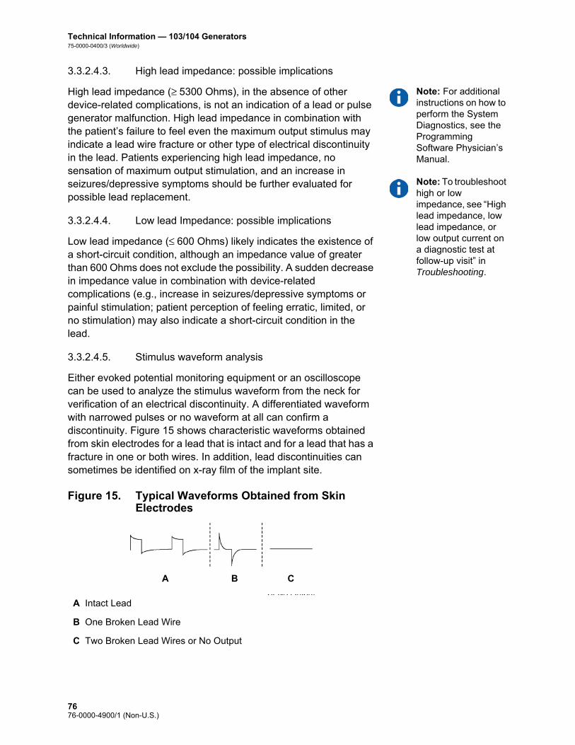
Technical Information — 103/104 Generators75-0000-0400/3 (Worldwide)
3.3.2.4.3. High lead impedance: possible implications
Note: For additional instructions on how to perform the System Diagnostics, see the Programming Software Physician’s Manual.
Note: To troubleshoot high or low impedance, see “High lead impedance, low lead impedance, or low output current on a diagnostic test at follow-up visit” in Troubleshooting.
High lead impedance (≥ 5300 Ohms), in the absence of other device-related complications, is not an indication of a lead or pulse generator malfunction. High lead impedance in combination with the patient’s failure to feel even the maximum output stimulus may indicate a lead wire fracture or other type of electrical discontinuity in the lead. Patients experiencing high lead impedance, no sensation of maximum output stimulation, and an increase in seizures/depressive symptoms should be further evaluated for possible lead replacement.
3.3.2.4.4. Low lead Impedance: possible implications
Low lead impedance (≤ 600 Ohms) likely indicates the existence of a short-circuit condition, although an impedance value of greater than 600 Ohms does not exclude the possibility. A sudden decrease in impedance value in combination with device-related complications (e.g., increase in seizures/depressive symptoms or painful stimulation; patient perception of feeling erratic, limited, or no stimulation) may also indicate a short-circuit condition in the lead.
3.3.2.4.5. Stimulus waveform analysis
Either evoked potential monitoring equipment or an oscilloscope can be used to analyze the stimulus waveform from the neck for verification of an electrical discontinuity. A differentiated waveform with narrowed pulses or no waveform at all can confirm a discontinuity. Figure 15 shows characteristic waveforms obtained from skin electrodes for a lead that is intact and for a lead that has a fracture in one or both wires. In addition, lead discontinuities can sometimes be identified on x-ray film of the implant site.
Figure 15. Typical Waveforms Obtained from Skin Electrodes
A Intact Lead
B One Broken Lead Wire
C Two Broken Lead Wires or No Output
A B C
7676-0000-4900/1 (Non-U.S.)

Technical Information — 103/104 Generators75-0000-0400/3 (Worldwide)
3.3.2.5. Delivery of programmed output current
3.3.2.5.1. LOW as output current
If the diagnostic tests indicate LOW output current, the pulse generator may not be delivering the programmed output current. Reasons for failure to deliver the programmed output current include high programmed output current and high lead impedance. The maximum deliverable output current, according to Ohm’s Law, equals the maximum output voltage (approximately 12 V) divided by the lead impedance.
3.3.2.5.2. Reprogram to a lower current
If the pulse generator is failing to deliver the programmed output current, the physician can reprogram the device to a lower output current and attempt to compensate for the decrease in delivered energy by widening the pulse width. For example, if the diagnostics read LOW for a pulse generator programmed at 2.5 mA, 30 Hz, 500 μsec with 30 seconds ON time, then the parameters may be changed by lowering the output current to 2 mA and widening the pulse width to 750 μsec.
3.3.2.6. Charge delivered per pulse
3.3.2.6.1. Output current x pulse width = charge delivered per pulse
The charge delivered per pulse is the most important parameter in evaluating stimulation output. It is defined as a microcoulomb (μC), which is the product of current and time—that is, the output current (mA) multiplied by the pulse width (msec). Figure 16 shows the relationship of delivered output current (mA) to lead impedance for a 1000 μsec pulse with output currents from 0 to 3.5 mA.
7776-0000-4900/1 (Non-U.S.)

Technical Information — 103/104 Generators75-0000-0400/3 (Worldwide)
Figure 16. Relationship of Delivered Output Current to Lead Impedance
3.3.2.7. Pulse generator battery longevity
3.3.2.7.1. Battery longevity and programmed setting choices
Caution: Undeliverable output currents— Programming the pulse generator to a high output current that cannot be delivered due to a high lead impedance may disproportionately increase the battery depletion rate and should be avoided.
The anticipated longevity of the pulse generator battery varies, depending on the choice of programmed settings. Higher output currents, frequencies, pulse widths, and duty cycles generally deplete the battery over a shorter period of time than lower settings. Generally, the increase in battery depletion rate is proportional to the increase in the programmed setting.
Other factors, such as the lead impedance and, if applicable, magnet usage, also affect the anticipated longevity of the pulse generator battery. The anticipated battery longevity decreases as lead impedance increases. Although 1.5 k to 3 kOhms may be a typical lead impedance at implantation, the impedance may increase to 3 k to 5 kOhms during the life of the implant.
For Models 103 and 104, the approximate battery longevity predicted is greater than 6 years at programmed settings of 20 Hz with a 500-μsec pulse width and 2-mA output current, a lead impedance of 4 kOhms, and a duty cycle of 10 percent. Appendix A — Model 103/104 Battery Longevity and Programmed Setting Choices provides estimated battery lifetimes under a variety of stimulation conditions, including lead impedance. Because of the number of possible parameter combinations, it is impractical to provide the projected life for all possible combinations. The tables should not be used to predict battery End of Service (EOS), but they give some indication of the effect of various parameter changes on battery life and can be used to assist in the selection of parameter settings. They also indicate that battery life can be maximized at low duty cycles and low frequencies (10 to 20 Hz) for stimulation.
7876-0000-4900/1 (Non-U.S.)

Technical Information — 103/104 Generators75-0000-0400/3 (Worldwide)
3.3.2.7.2. Battery status indicators
Caution: Battery evaluation at cold temperatures—Low storage temperatures may affect the battery status indicators. In such cases, the battery status indicators should be re-evaluated using the System Diagnostics or Generator Diagnostics after the pulse generator has been at room or body temperature for 30 minutes.
The programming software displays a battery indicator for the pulse generator similar to an indicator that may be found in cell phones. The visual indicator illustrates the approximate remaining battery capacity.
The programming software will display warning messages after an interrogation or programming of the pulse generator if the battery has been depleted to a level where action is recommended due to approaching or reaching End of Service (EOS). Please refer to the VNS Therapy Programming Software Physician’s Manual for additional information in these indicators.
3.3.3. Pulse Generator Replacement
All VNS Therapy pulse generators eventually require surgical replacement as a result of battery depletion. pulse generator replacement does not, of itself, require lead replacement unless a lead discontinuity is suspected. pulse generator replacement or removal requires dissection to the pulse generator’s pocket, with care being taken not to damage or cut the lead. The entire surgical procedure generally requires about 1 hour.
3.3.4. Lead Lifetime and Replacement
A lead requires replacement when a lead discontinuity is suspected. An increase in clinical signs and symptoms may signal a need for lead replacement. Events that can shorten the life expectancy of the lead are as follows: Blunt trauma to the neck and/or any area of the body beneath
which the lead is implanted
Twisting or picking (Twiddler’s Syndrome) at either the implanted lead or the pulse generator
Improper surgical implantation of the VNS Therapy System, including (but not limited to) providing an inadequate strain-relief loop, placing sutures directly on the lead body rather than using the tie-downs, and suturing the lead body to muscle
Caution: Lead replacement or removal—Replacing or removing leads because of lack of efficacy is a medical judgement that includes the patient’s desires and health status, and must be carefully weighed against the known and unknown risks of surgery. At present, no known long-term hazards or risks are associated with leaving the lead implanted, beyond those already mentioned in this physician’s manual. All precautions and contraindications still should be observed (see Troubleshooting.)
7976-0000-4900/1 (Non-U.S.)

Technical Information — 103/104 Generators75-0000-0400/3 (Worldwide)
3.3.5. Signs of End of Service
Caution: Pulse generator EOS may result in increased frequency, intensity, or duration of signs and symptoms of the patient’s disorder, in some cases to levels greater than those reported before stimulation.
The most common reason for the absence of stimulation is battery depletion, although there may be other reasons. When end of service (EOS) occurs, the pulse generator will disable stimulation and no output will be delivered. If the pulse generator is not explanted or replaced at EOS, the battery voltage will continue to gradually decrease and communication with the pulse generator may not be possible.
3.3.6. Replacement Based on Battery Status Indicators
Note: See “Battery status indicators”.
The pulse generators and programming software have battery status indicators. These indicators provide warnings that a pulse generator battery should be monitored more frequently, is near EOS, or has reached EOS. Once these warning messages appear, see recommendations in the physician’s manual for the programming software.
Caution: Prompt pulse generator replacement—Cyberonics recommends prompt replacement of the pulse generator at or before EOS. Prompt replacement may help minimize any possible relapse.
Caution: Explanted pulse generator—A pulse generator explanted for any reason should not be reimplanted. An explanted pulse generator should be returned to Cyberonics. (For instructions on returning an explanted pulse generator, see the Introduction to the VNS Therapy System chapter.)
8076-0000-4900/1 (Non-U.S.)

Technical Information—105 Generator
AspireHC®—Model 105
81 76-0000-4900/1 (Non-U.S.)

Technical Information — 105 Generator75-0000-0500/3 (Worldwide)
4. TECHNICAL INFORMATION — 105 GENERATOR _____________
4.1. Detailed Device Description
4.1.1. Physical Characteristics
The titanium case of the VNS Therapy AspireHC® Model 105 Generator is hermetically sealed and leak-rate tested. Specially designed feedthroughs using platinum conductors form the electrical connection from the connector blocks to the circuitry through the hermetically sealed enclosure. The Model 105 accepts the single-pin lead.
4.1.2. Biological Compatibility
Materials exposed to the subcutaneous environment are biologically compatible. All of these materials have a long history in medical implants and have been found to be tissue compatible.
4.1.3. Power Source
The power source for the Model 105 pulse generators is a Wilson Greatbatch Ltd, Model 2075, lithium carbon monofluoride battery with an open-circuit voltage of 3.3 V. The battery’s maximum available capacity is approximately 1.7 Amp-hours. The self-discharge reduces the capacity by less than 1 percent per year. The voltage in this battery gradually decreases as the battery nears its end of service (EOS).
4.1.4. Circuitry
The pulse generator uses complementary metal oxide semiconductor (CMOS) integrated circuits, including a microprocessor. The circuitry is functionally represented in Figure 17.
8276-0000-4900/1 (Non-U.S.)

Technical Information — 105 Generator75-0000-0500/3 (Worldwide)
For descriptive purposes, circuitry of the pulse generator can be divided into the following major functional sections:
Figure 17. Pulse Generator Circuitry
4.1.5. Identification
The pulse generator can be identified on an x-ray film and will appear as shown in Figure 18. The serial number and model number of the pulse generator are marked on its titanium case, but do not appear on the x-ray film.
Voltage regulator Regulates the system power supply
Crystal oscillator Provides a timing reference
Logic and control Controls overall pulse generator function; receives and implements programming commands; collects and stores telemetry information
Output Develops and modulates signals delivered to the lead
Antenna Receives programming signals; transmits telemetry information to the programming wand
Reed switch Provides a mechanism to place the pulse generator in Magnet Mode or to inhibit its output
A Battery E Antenna
B Voltage Regulator F Output
C Crystal Oscillator G Reed Switch
D Logic and Control H Lead Electrodes
A
G
HF
C
B D
E
8376-0000-4900/1 (Non-U.S.)

Technical Information — 105 Generator75-0000-0500/3 (Worldwide)
Note: See the Programming Software Physician’s Manual for details.
The serial number, model number, and year of manufacture can be identified by interrogating the pulse generator with the programming software.
Note: CYBX is the identification code for Cyberonics.
Figure 18. X-ray Identification
4.2. VNS Therapy System Compatibility
Model 105 is compatible with these system components:
4.3. Directions for Use
4.3.1. Specifications and Product Information
The specifications and product information for the VNS Therapy Model 105 pulse generator is presented in Table 12.
Component Model
Lead single-pin
Wand 201
Software 250 v 8.0+
Tunneler 402
Accessory Pack 502
Magnets 220
8476-0000-4900/1 (Non-U.S.)

Technical Information — 105 Generator75-0000-0500/3 (Worldwide)
Table 12. Specifications and Product Information
Stimulation Parameters
Available Parameter Settings
Output current 0-3.5 mA in 0.25-mA steps (± 0.1 mA or ± 10%; whichever is greater)
Signal frequency 1, 2, 5, 10, 15, 20, 25, 30 Hz ± 6%
Pulse width 130, 250, 500, 750, 1000 μsec ± 10%
Signal ON time 7, 14, 21, 30, 60 secNormal Mode (+ 7sec / - 15%)Magnet Mode (+ 15% / - 7sec)
Signal OFF time 0.2, 0.3, 0.5, 0.8, 1.1, 1.8, 3 min, and 5 to 180 min (5 to 60 in 5-min steps; 60 to 180 in 30-min steps) + 4.4 / - 8.4 sec or ± 1%, whichever is greater
Magnet activation Provided by magnet application (output current, pulse width, and signal ON time may be independently programmed for this purpose)
Reset parameters Settings are unchanged, but output is disabled (0 mA)
Telemetry Reports
Device History Report Patient ID, implant date, model number, serial number, magnet activations, total ON time, total operating time, and manufacturing date
Device Diagnostic Report
Patient ID, model ID, serial number, implant date, communication status, output current status, measured current delivered, lead impedance, and battery status indicators (IFI, N EOS, EOS)
Power Source
Battery Wilson Greatbatch Ltd., Model 2075
Chemistry Lithium carbon monofluoride
Voltage 3.3 V, open circuit
Rated capacity 1.7 Amp-hour
Self-discharge rate < 1% per year
8576-0000-4900/1 (Non-U.S.)

Technical Information — 105 Generator75-0000-0500/3 (Worldwide)
4.3.2. Operating Characteristics
4.3.2.1. Communicating with the VNS Therapy System
4.3.2.1.1. Programming software
Note: For more information, including a list of computers that have been qualified for use with this software, see the Programming Software Physician’s Manual.
The pulse generator can be programmed with the VNS Therapy programming software.
The programming software is used on a computer, supplied by Cyberonics, that is dedicated only to programming the VNS Therapy System.
4.3.2.1.2. Programming wand
Note: For proper placement of the programming wand, connection of the wand to the computer, and use of the wand, see the Programming Wand Physician’s Manual.
A programming wand connected to a compatible computer running the programming software is needed to communicate with the pulse generator (For a list of compatible computers, see the Programming Software Physician’s Manual).
4.3.2.1.3. Prompts and messages
After the program has been initiated, the software screens display prompts and messages to aid in communicating with the pulse generator.
Physical Characteristics—Materials
Case Titanium, hermetically sealed
Header Polyurethane — Tecothane™ TT-1075D-M Thermoplastic
Lead connector blocks Stainless steel
Setscrew plug(s) Silicone*
Measurements (Typical)
Lead receptacle(s) 0.126 in (3.2 mm) nominal
Dimensions 2.0 in x 2.0 in x .27 in(52 mm x 52 mm x 6.9 mm)
Weight 0.88 oz (25 g)
Connector Retention Strength
With VNS Therapy lead
> 10 N
* No component of the VNS Therapy System is made with natural rubber latex.
8676-0000-4900/1 (Non-U.S.)

Technical Information — 105 Generator75-0000-0500/3 (Worldwide)
4.3.2.1.4. Communication
The pulse generator “listens” for a communication signal from the programming wand. Communication usually takes between 1 and 4 seconds, but may be prolonged or interrupted in the presence of electromagnetic interference (EMI). The pulse generator listens for and implements interrogations, parameter programming instructions, requests for Device Diagnostics testing, and Device History inquiries.
Note: For details on viewing database information, see the Programming Software Physician’s Manual.
In response, the pulse generator transmits information on the stimulation parameter settings, changes its parameter settings, responds to requests for Device Diagnostics testing, and provides device histories, respectively. Each time these data are transmitted by the pulse generator, they are saved by the programming software to a database.
In addition to the programming software and programming wand combination, the magnet can be used for one-way communication to the pulse generator by activating a reed switch in the electronic circuitry. The magnet can be used to initiate stimulation, temporarily inhibit stimulation, perform Magnet Mode diagnostics, and reset the pulse generator.
4.3.2.1.5. Normal Mode
After the pulse generator has been programmed, the stimulation will repeat in accordance with the programmed ON and OFF cycle (Normal Mode) until the pulse generator receives communication from the VNS Therapy programming system or until it is inhibited with the magnet. Immediately after successful programming, the pulse generator delivers a programmed stimulation that enables the programmer to evaluate patient response. If programming is performed during stimulation, stimulation will be terminated; after programming, stimulation will begin, using the revised settings.
4.3.2.1.6. Magnet Mode
Magnet Mode produces on-demand stimulation for the programmed magnet ON time. Stimulation is initiated by applying or passing the magnet over the pulse generator for at least 1 second and then immediately removing it from the area over the pulse generator. Stimulation is delivered after the magnet is removed. The Magnet Mode uses the same frequency as the Normal Mode, but the output current, pulse width, and signal ON time are independently programmable. The Directions for Use are equivalent for epilepsy and depression, with the following exceptions:
8776-0000-4900/1 (Non-U.S.)

Technical Information — 105 Generator75-0000-0500/3 (Worldwide)
For patients with depression, the Magnet Mode output current should always be programmed at 0 mA, the setting at which the pulse generator is shipped from Cyberonics.
Use of the Magnet Mode is limited to patients with epilepsy. Patients with epilepsy or their caregivers pass the magnet over the implanted pulse generator to activate on-demand delivery of a single train of vagus nerve stimulation and help abort or diminish a seizure.
Magnet Mode is not used for patients with depression.
4.3.2.1.7. Pulse generator interrogation
The pulse generator can be interrogated to determine the present settings of the stimulation parameters.
4.3.2.1.8. Programmable parameters
A graphic representation of stimulation (Figure 19) depicts the relationship of the programmable parameters. Each parameter can be independently programmed, thereby offering multiple setting combinations from which the physician may select optimal stimulation for the patient.
Figure 19 shows that the output pulse can be varied both by amplitude (output current) and duration (pulse width). The number of output pulses delivered per second determines the frequency.
Figure 19. Stimulation (Frequencies < 10 Hz do not ramp)
A Stimulation Time E Output Current
B Ramp Up (2 sec.) F 1/Signal Frequency
C On Time G Pulse Width
D Ramp Down (2 sec.) H Off Time
AB C D
E
GHF
8876-0000-4900/1 (Non-U.S.)

Technical Information — 105 Generator75-0000-0500/3 (Worldwide)
4.3.2.1.9. Duty cycle
Caution: Possible nerve damage with ON time > OFF time— Excessive stimulation has resulted in degenerative nerve damage in laboratory animals. One component of excessive stimulation is when ON time exceeds OFF time, which can be produced by continuous or frequent magnet activation (> 8 hours). Cyberonics recommends that stimulation at these combinations of ranges be avoided.
The percentage of time the pulse generator is stimulating is called a “duty cycle.” A duty cycle is calculated by dividing the stimulation time (programmed ON time plus, if frequency is ≥ 10 Hz, 2 seconds of ramp-up time and 2 seconds of ramp-down time) by the sum of the ON and OFF times. The various parameter settings for stimulation are listed in “Specifications and Product Information”.
Table 13 shows duty cycles for typical ON time and OFF time settings.
Table 13. Duty Cycles for Various ON and OFF Time Settings
4.3.2.1.10. Parameter settings and battery life
Note: See “Pulse generator battery longevity”.
When selecting a combination of parameter settings for stimulation, the physician should also consider that some combinations would decrease battery life faster than others.
4.3.2.2. VNS Therapy magnets
There are four possible uses of the magnet: Epilepsy Only — To provide on-demand stimulation as an
attempt to abort or de-intensify an oncoming seizure
To temporarily inhibit stimulation
To reset the pulse generator (in combination with the programming wand)
OFF Time (min)
0.2 0.3 0.5 0.8 1.1 1.8
ON Time (sec)
Duty Cycles* (% ON Time)
7 58 44 30 20 15 10
14 69 56 41 29 23 15
21 76 64 49 36 29 19
30 81 71 57 44 35 25
60 89 82 71 59 51 38
* A duty cycle is calculated by dividing stimulation time (programmed ON time plus 2 seconds of ramp-up time and 2 seconds of ramp-down time) by the sum of the ON time and the OFF time.
* The duty cycles in gray are not recommended as they represent parameter combinations with ON Time > OFF Time.
8976-0000-4900/1 (Non-U.S.)

Technical Information — 105 Generator75-0000-0500/3 (Worldwide)
Caution: Possible nerve damage with ON time > OFF time— Excessive stimulation has resulted in degenerative nerve damage in laboratory animals. One component of excessive stimulation is when ON time exceeds OFF time, which can be produced by continuous or frequent magnet activation (> 8 hours). Cyberonics recommends that stimulation at these combinations of ranges be avoided.
Epilepsy Only — To test daily the functioning of the pulse generator, Cyberonics recommends that patients be instructed to use the magnet to activate stimulation. During an aura or at the start of a seizure, magnet activation may be initiated by the patient, a companion, or the physician by applying or passing the magnet over the pulse generator to activate a reed switch in the pulse generator’s electronic circuitry. This action changes the pulse generator from Normal Mode to Magnet Mode.
Two identical magnets (see Figure 20), each providing a minimum of 50 gauss at 1 inch, are supplied by Cyberonics. A Cyberonics watch-style magnet attaches to a wristband in the same manner as a wristwatch, and a Cyberonics pager-style magnet attaches to a belt in the same manner as a pager with a quick-release mechanism.
Figure 20. Magnet Styles
Epilepsy Only — The proper orientation and motion for initiating magnet activation is shown in Figure 21. The magnet is shown without the belt clip or wristband to illustrate the proper orientation of the magnet to the pulse generator.
A Cyberonics Magnet (watch-style)
B Cyberonics Magnet (pager-style)
A B
9076-0000-4900/1 (Non-U.S.)
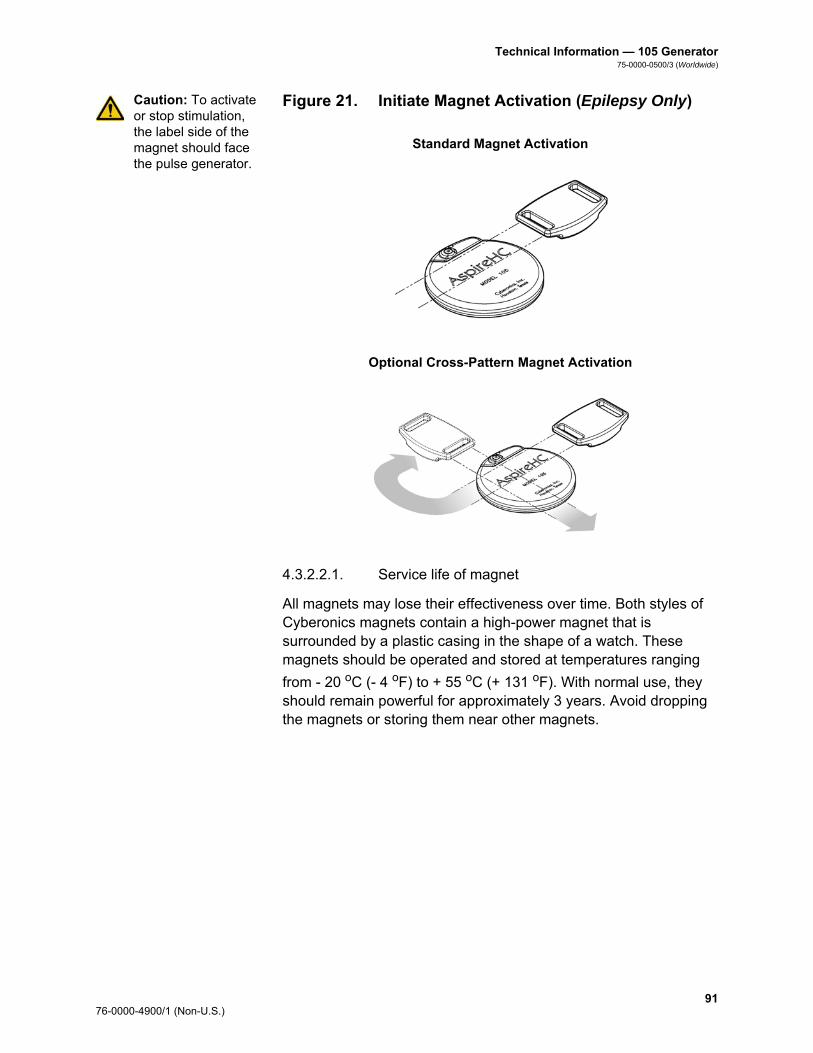
Technical Information — 105 Generator75-0000-0500/3 (Worldwide)
Caution: To activate or stop stimulation, the label side of the magnet should face the pulse generator.
Figure 21. Initiate Magnet Activation (Epilepsy Only)
4.3.2.2.1. Service life of magnet
All magnets may lose their effectiveness over time. Both styles of Cyberonics magnets contain a high-power magnet that is surrounded by a plastic casing in the shape of a watch. These magnets should be operated and stored at temperatures ranging
from - 20 oC (- 4 oF) to + 55 oC (+ 131 oF). With normal use, they should remain powerful for approximately 3 years. Avoid dropping the magnets or storing them near other magnets.
Standard Magnet Activation
Optional Cross-Pattern Magnet Activation
9176-0000-4900/1 (Non-U.S.)

Technical Information — 105 Generator75-0000-0500/3 (Worldwide)
Caution: The cross-pattern swipe technique may cause duplicate magnet activation entries to be shown in the programming software database. This is an expected occurrence due to device design and is not considered a device malfunction. See the Programming Software Physician’s Manual for more details.
4.3.2.2.2. Magnet activation technique (epilepsy only)
To initiate stimulation, apply or pass the magnet over the pulse generator for at least 1 second and then immediately remove it from the area over the pulse generator. A cross-pattern swipe, as shown in Figure 21, may also be used by the patient or caregiver to activate the Magnet Mode if difficulty is encountered with a single pass of the magnet. Removal of the magnet causes the pulse generator to operate in Magnet Mode, delivering a single stimulation at the programmed magnet pulse width, magnet current, and magnet signal ON time settings. The frequency is the programmed value for Normal Mode. A Magnet Mode stimulation will always override any Normal Mode programmed stimulation, even if the Magnet Mode output current is set to 0 mA. If Magnet Mode stimulation is not desired, the Magnet Mode output current may be programmed to 0 mA.
Cyberonics recommends that tests of the magnet output be performed while the patient is still in the physician’s office to ensure tolerability of the magnet output.
4.3.2.2.3. Inhibit pulse generator output with the magnet
Caution: If stimulation becomes painful, the patient should be instructed to stop the stimulation with the magnet.
Application of the magnet during stimulation will inhibit the output. In addition, holding the magnet in place for at least 65 seconds will terminate any ongoing Normal Mode stimulation. After the magnet is removed, Normal Mode operation will resume with stimulation when one complete OFF time has elapsed.
Note: See “Adverse Events” in the indication-specific information chapters.
In the unlikely event of continuous stimulation or other malfunction, the patient must be advised to apply the magnet, secure it in place, and immediately notify their physician.
9276-0000-4900/1 (Non-U.S.)

Technical Information — 105 Generator75-0000-0500/3 (Worldwide)
4.3.2.2.4. Reset the microprocessor with the magnet and the programming wand
Caution: Pulse generator reset— When the pulse generator is reset, its stimulation output is disabled (0 mA); however, all settings and device history are preserved. After a successful reset, the pulse generator stimulation output may be re-enabled to resume operation at the previously programmed settings.
The VNS Therapy System allows the pulse generator microprocessor to be reset in the event of a malfunction. Resetting is necessary only in the rare case of microprocessor memory malfunction, which might be caused by conditions described in the Introduction to the VNS Therapy System chapter. Resetting the microprocessor may be appropriate when the pulse generator and the programming wand are unable to communicate.
For suggestions in solving communication difficulties, see: Troubleshooting
“Troubleshooting” in the Programming Wand Physician’s manual
“Precautions” and “Troubleshooting” in the Programming Software Physician’s Manual
For instructions on how to reset the microprocessor, see the Programming Wand Physician’s Manual. After a microprocessor reset has been attempted, wait at least 30 seconds before establishing communication with the programming software. It is recommended, except in cases of a medical emergency, that the physician consult a Cyberonics technical representative before a reset is performed.
4.3.2.3. Device history
The Device History consists of the pulse generator serial number, model number, the patient code (usually three initials), implantation date, year of manufacture, and other information pertinent to diagnostic and programming events. Use the programming software to access and view Device History information.
4.3.2.4. Device diagnostics
Note: For details on available diagnostic tests, see the Programming Software Physician’s Manual.
Information from device diagnostic tests can help the physician determine whether the: Pulse generator is operating properly before it is implanted
Pulse generator output current is being delivered at the programmed value
Pulse generator is operating in Normal or Magnet Mode
Lead impedance is within an acceptable range
9376-0000-4900/1 (Non-U.S.)

Technical Information — 105 Generator75-0000-0500/3 (Worldwide)
4.3.2.4.1. System Diagnostics test
The System Diagnostics evaluates the lead impedance of the VNS Therapy System, as well as the pulse generator’s ability to deliver the programmed stimulation. When the output current is programmed to any value greater than 0 mA, the pulse generator will deliver a pulse at 0.25 mA, 130 μsec to assess lead impedance. The pulse generator will then deliver the programmed output stimulus. The programming software will report the lead impedance and whether the programmed stimulus was delivered.
If the output current is programmed to 0 mA, as would be expected during the implantation procedure, the pulse generator will deliver a pulse at 0.25 mA, 130 μsec followed by delivery of stimulation at 1 mA, 20 Hz, 500 μsec for approximately 14 seconds. Likewise, the programming software will report the lead impedance and whether the parameters listed here are deliverable.
4.3.2.4.2. Reasons for high or low lead impedance readings
The System Diagnostics evaluates lead impedance of the VNS Therapy System. The lead impedance measurement is performed with a single pulse at 0.25 mA, 130 μsec. Additionally, the pulse generator automatically performs a lead impedance measurement once every 24 hours. If a HIGH or LOW impedance is detected, the user is notified after an interrogation with the programming software.
High lead impedance is defined as any value ≥ 5300 Ohms. Low lead impedance is defined as any value ≤ 600 Ohms.
Caution: Possible causes of high lead impedance readings are thought to include: lead discontinuity, lead disconnection from the pulse generator, fibrosis between the nerve and the electrode, electrode detachment from the nerve, or a defective pulse generator.
Caution: Possible causes of low lead impedance readings are thought to include: short-circuit condition within the lead or a defective pulse generator.
9476-0000-4900/1 (Non-U.S.)

Technical Information — 105 Generator75-0000-0500/3 (Worldwide)
4.3.2.4.3. High lead impedance: possible implications
Note: For additional instructions on how to perform the System Diagnostics, see the Programming Software Physician’s Manual.
Note: To troubleshoot high or low impedance see “High lead impedance, low lead impedance, or low output current on a diagnostic test at follow-up visit” in the Troubleshooting chapter.
High lead impedance (≥ 5300 Ohms), in the absence of other device-related complications, is not an indication of a lead or pulse generator malfunction. High lead impedance in combination with the patient’s failure to feel even the maximum output stimulus may indicate a lead wire fracture or other type of electrical discontinuity in the lead. Patients experiencing high lead impedance, no sensation of maximum output stimulation, and an increase in seizures/depressive symptoms should be further evaluated for possible lead replacement.
4.3.2.4.4. Low lead Impedance: possible implications
Low lead impedance (≤ 600 Ohms) likely indicates the existence of a short-circuit condition, although an impedance value of greater than 600 Ohms does not exclude the possibility. A sudden decrease in impedance value in combination with device-related complications (e.g., increase in seizures/depressive symptoms or painful stimulation; patient perception of feeling erratic, limited, or no stimulation) may also indicate a short-circuit condition in the lead.
4.3.2.4.5. Stimulus waveform analysis
Either evoked potential monitoring equipment or an oscilloscope can be used to analyze the stimulus waveform from the neck for verification of an electrical discontinuity. A differentiated waveform with narrowed pulses or no waveform at all can confirm a discontinuity. Figure 22 shows characteristic waveforms obtained from skin electrodes for a lead that is intact and for a lead that has a fracture in one or both wires. In addition, lead discontinuities can sometimes be identified on x-ray film of the implant site.
Figure 22. Typical Waveforms Obtained from Skin Electrodes
A Intact Lead
B One Broken Lead Wire
C Two Broken Lead Wires or No Output
A B C
9576-0000-4900/1 (Non-U.S.)

Technical Information — 105 Generator75-0000-0500/3 (Worldwide)
4.3.2.5. Delivery of programmed output current
4.3.2.5.1. LOW as output current
If the diagnostic tests indicate LOW output current, the pulse generator may not be delivering the programmed output current. Reasons for failure to deliver the programmed output current include high programmed output current and high lead impedance. The maximum deliverable output current, according to Ohm’s Law, equals the maximum output voltage (approximately 12 V) divided by the lead impedance.
4.3.2.5.2. Reprogram to a lower current
If the pulse generator is failing to deliver the programmed output current, the physician can reprogram the device to a lower output current and attempt to compensate for the decrease in delivered energy by widening the pulse width. For example, if the diagnostics read LOW for a pulse generator programmed at 2.5 mA, 30 Hz, 500 μsec with 30 seconds ON time, then the parameters may be changed by lowering the output current to 2 mA and widening the pulse width to 750 μsec.
4.3.2.6. Charge delivered per pulse
4.3.2.6.1. Output current x pulse width = charge delivered per pulse
The charge delivered per pulse is the most important parameter in evaluating stimulation output. It is defined as a microcoulomb (μC), which is the product of current and time—that is, the output current (mA) multiplied by the pulse width (msec). Figure 23 shows the relationship of delivered output current (mA) to lead impedance for a 1000 μsec pulse with output currents from 0 to 3.5 mA.
9676-0000-4900/1 (Non-U.S.)

Technical Information — 105 Generator75-0000-0500/3 (Worldwide)
Figure 23. Relationship of Delivered Output Current to Lead Impedance
4.3.2.7. Pulse generator battery longevity
4.3.2.7.1. Battery longevity and programmed setting choices
Caution: Undeliverable output currents— Programming the pulse generator to a high output current that cannot be delivered due to a high lead impedance may disproportionately increase the battery depletion rate and should be avoided.
The anticipated longevity of the pulse generator battery varies, depending on the choice of programmed settings. Higher output currents, frequencies, pulse widths, and duty cycles generally deplete the battery over a shorter period of time than lower settings. Generally, the increase in battery depletion rate is proportional to the increase in the programmed setting.
Other factors, such as the lead impedance and, if applicable, magnet usage, also affect the anticipated longevity of the pulse generator battery. The anticipated battery longevity decreases as lead impedance increases. Although 1.5 k to 3 kOhms may be a typical lead impedance at implantation, the impedance may increase to 3 k to 5 kOhms during the life of the implant.
Note: For more information, see the Programming Software Physician’s Manual.
Appendix B — Model 105 Battery Longevity and Programmed Setting Choices provides estimated battery lifetimes under a variety of stimulation conditions, including lead impedance. Because of the number of possible parameter combinations, it is impractical to provide the projected life for all possible combinations. The tables should not be used to predict battery end of service (EOS), but they give some indication of the effect of various parameter changes on battery life and can be used to assist in the selection of parameter settings. They also indicate that battery life can be maximized at low duty cycles and low frequencies (10 to 20 Hz) for stimulation.
9776-0000-4900/1 (Non-U.S.)

Technical Information — 105 Generator75-0000-0500/3 (Worldwide)
4.3.2.7.2. Battery status indicators
Caution: Battery evaluation at cold temperatures—Low storage temperatures may affect the battery status indicators. In such cases, the battery status indicators should be re-evaluated using the System Diagnostics or Generator Diagnostics after the pulse generator has been at room or body temperature for 30 minutes.
The programming software displays a battery indicator similar to an indicator that may be found in cell phones. The visual indicator illustrates the approximate remaining battery capacity.
The programming software will display warning messages after an interrogation or programming of the pulse generator if the battery has been depleted to a level where action is recommended due to approaching or reaching End of Service (EOS). Please refer to the VNS Therapy Programming Software Physician’s Manual for additional information on these indicators.
4.3.3. Pulse Generator Replacement
All VNS Therapy pulse generators eventually require surgical replacement as a result of battery depletion. pulse generator replacement does not, of itself, require lead replacement unless a lead discontinuity is suspected. pulse generator replacement or removal requires dissection to the pulse generator’s pocket, with care being taken not to damage or cut the lead. The entire surgical procedure generally requires about 1 hour.
4.3.4. Lead Lifetime and Replacement
A lead requires replacement when a lead discontinuity is suspected. An increase in clinical signs and symptoms may signal a need for lead replacement. Events that can shorten the life expectancy of the lead are as follows: Blunt trauma to the neck and/or any area of the body beneath
which the lead is implanted
Twisting or picking (Twiddler’s Syndrome) at either the implanted lead or the pulse generator
Improper surgical implantation of the VNS Therapy System, including (but not limited to) providing an inadequate strain-relief loop, placing sutures directly on the lead body rather than using the tie-downs, and suturing the lead body to muscle
Caution: Lead replacement or removal—Replacing or removing leads because of lack of efficacy is a medical judgement that includes the patient’s desires and health status, and must be carefully weighed against the known and unknown risks of surgery. At present, no known long-term hazards or risks are associated with leaving the lead implanted, beyond those already mentioned in this physician’s manual. All precautions and contraindications still should be observed (see Troubleshooting).
9876-0000-4900/1 (Non-U.S.)

Technical Information — 105 Generator75-0000-0500/3 (Worldwide)
4.3.5. Signs of End of Service
Caution: Pulse generator EOS may result in increased frequency, intensity, or duration of signs and symptoms of the patient’s disorder, in some cases to levels greater than those reported before stimulation.
The most common reason for the absence of stimulation is battery depletion, although there may be other reasons. When end of service (EOS) occurs, the pulse generator will disable stimulation and no output will be delivered. If the pulse generator is not explanted or replaced at EOS, the battery voltage will continue to gradually decrease and communication with the pulse generator may not be possible.
4.3.6. Replacement Based on Battery Status Indicators
Note: See “Battery status indicators”.
The pulse generators and programming software have battery status indicators. These indicators provide warnings that a pulse generator battery should be monitored more frequently, is nearing EOS, or has reached EOS. Once these warning messages appear, see recommendations in the Programming Software Physician’s Manual.
Caution: Prompt pulse generator replacement—Cyberonics recommends prompt replacement of the pulse generator at or before EOS. Prompt replacement may help minimize any possible relapse.
Caution: Explanted pulse generator—A pulse generator explanted for any reason should not be reimplanted. An explanted pulse generator should be returned to Cyberonics. (For instructions on returning an explanted pulse generator, see the Introduction to the VNS Therapy System chapter.)
9976-0000-4900/1 (Non-U.S.)

Technical Information — 105 Generator75-0000-0500/3 (Worldwide)
10076-0000-4900/1 (Non-U.S.)

Technical Information—106 Generator
AspireSR®— Model 106
101 76-0000-4900/1 (Non-U.S.)

Technical Information — 106 Generator75-0000-8300/3 (Non-U.S.)
5. TECHNICAL INFORMATION — 106 GENERATOR _____________
5.1. Detailed Device Description
5.1.1. Physical Characteristics
The titanium case of the VNS Therapy® AspireSR® Model 106 generator is hermetically sealed and leak-rate tested. Specially designed feedthroughs using platinum conductors form the electrical connection from the connector blocks to the circuitry through the hermetically sealed enclosure. The Model 106 accepts the single-pin lead.
5.1.2. Biological Compatibility
Materials exposed to the subcutaneous environment are biologically compatible. All of these materials have a long history in medical implants and have been found to be tissue compatible.
5.1.3. Power Source
The power source for the Model 106 pulse generators is a Wilson Greatbatch Ltd, Model 2075, lithium carbon monofluoride battery with an open-circuit voltage of 3.3 V. The battery’s maximum available capacity is approximately 1.7 Amp-hours. The self-discharge reduces the capacity by less than 1 percent per year. The voltage in this battery gradually decreases as the battery nears its end of service (EOS).
5.1.4. Circuitry
The pulse generator uses complementary metal oxide semiconductor (CMOS) integrated circuits, including a microprocessor. The circuitry is functionally represented in Figure 24.
For descriptive purposes, circuitry of the pulse generator can be divided into the following major functional sections:
Voltage regulators Regulates the system power supplies
Crystal oscillator Provides a timing reference
Logic and control Controls overall pulse generator function; receives and implements programming commands; collects and stores telemetry information, processes sensory input, and controls scheduled and sensory-based therapy outputs
10276-0000-4900/1 (Non-U.S.)

Technical Information — 106 Generator75-0000-8300/3 (Non-U.S.)
Figure 24. Pulse Generator Circuitry
5.1.5. Identification
The pulse generator can be identified on an x-ray film and will appear as shown in Figure 25. The serial number and model number of the pulse generator are marked on its titanium case, but do not appear on the x-ray film.
Note: See the Programming Software Physician’s Manual for details.
The serial number, model number, and year of manufacture can be identified by interrogating the pulse generator with the programming software.
Output Develops and modulates signals delivered to the lead
Antenna Receives programming signals; transmits telemetry information to the programming wand
Reed switch Provides a mechanism to place the pulse generator in Magnet Mode or to inhibit its output
Input/Output Switch Matrix
Allows the traditional VNS electrodes to serve as both therapy outputs and sensing input connections
A Battery F Input/Output Switch Matrix
B Voltage Regulator G Reed Switch
C Crystal Oscillator H Lead Electrodes
D Logic and Control I M106 Titanium Can Connection
E Antenna
A B D
F
H
G
C E
I
10376-0000-4900/1 (Non-U.S.)
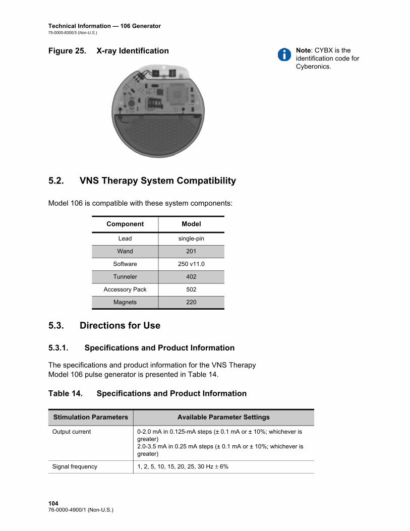
Technical Information — 106 Generator75-0000-8300/3 (Non-U.S.)
Note: CYBX is the identification code for Cyberonics.
Figure 25. X-ray Identification
5.2. VNS Therapy System Compatibility
Model 106 is compatible with these system components:
5.3. Directions for Use
5.3.1. Specifications and Product Information
The specifications and product information for the VNS Therapy Model 106 pulse generator is presented in Table 14.
Table 14. Specifications and Product Information
Component Model
Lead single-pin
Wand 201
Software 250 v11.0
Tunneler 402
Accessory Pack 502
Magnets 220
Stimulation Parameters Available Parameter Settings
Output current 0-2.0 mA in 0.125-mA steps (± 0.1 mA or ± 10%; whichever is greater)2.0-3.5 mA in 0.25 mA steps (± 0.1 mA or ± 10%; whichever is greater)
Signal frequency 1, 2, 5, 10, 15, 20, 25, 30 Hz ± 6%
10476-0000-4900/1 (Non-U.S.)

Technical Information — 106 Generator75-0000-8300/3 (Non-U.S.)
Pulse width 130, 250, 500, 750, 1000 μsec ± 10%
Signal ON time Normal Mode—7, 14, 21, 30, 60 sec (+ 7 sec/- 15%)Magnet Mode—7, 14, 21, 30, 60 sec (+ 15%/- 7sec)AutoStim Mode—30, 60 sec (+ 15%/- 7sec)
Signal OFF time 0.2, 0.3, 0.5, 0.8, 1.1, 1.8, 3 min, and 5 to 180 min (5 to 60 in 5-min steps; 60 to 180 in 30-min steps) ± 4.4 sec or ± 1%, whichever is greater
Magnet activation Provided by magnet application (output current, pulse width, and signal ON time may be independently programmed for this purpose)
Reset parameters Settings are unchanged, but output is disabled (0 mA)
Detection Configuration Parameters
Seizure Detection ON or OFF; allows VNS to operate in standard mode (i.e. no seizure detection - “OFF” setting) or a combination of standard VNS with detection (i.e. Seizure Detection -”ON” setting)
Threshold for AutoStim Threshold for ictal tachycardia heart rate increase, which triggers Automatic Stimulation (AutoStim). Setting range is from 20% to 70%. 20% is most sensitive. 70% is least sensitive.
Heartbeat Detection (Sensitivity)
Adjustable sensitivity parameter for heart beat detection, ranging from 1 to 5, with “1” being the least sensitive and “5” being the most sensitive setting. Note that the Model 106 is only capable of detecting heart beats in the range between 32 and 240 bpm (± 10% or 5 bpm, whichever is greater)
Verify Heartbeat Detection Feature on the programming software that when activated, configures the Model 106 to emit a pulse signal when a heartbeat is detected (for 2 minutes). May be used to check heartbeat detection performance at the currently programmed Heartbeat Detection setting.
Telemetry Reports
Device History Report Patient ID, implant date, model number, serial number, magnet activations, total ON time, total operating time, manufacturing date and device settings and stimulation statistics for last 3 office visits
Device Diagnostic Report Patient ID, model ID, serial number, firmware build number, implant date, communication status, output current status, measured current delivered, lead impedance, and battery status indicators (IFI, N EOS, EOS)
Power Source
Battery Wilson Greatbatch Ltd., Model 2075
Chemistry Lithium carbon monofluoride
Voltage 3.3 V, open circuit
Rated capacity 1.7 Amp-hour
Self-discharge rate < 1% per year
10576-0000-4900/1 (Non-U.S.)

Technical Information — 106 Generator75-0000-8300/3 (Non-U.S.)
5.3.2. Operating Characteristics
5.3.2.1. Communicating with the VNS Therapy System
5.3.2.1.1. Programming software
Note: For more information see the Programming Software Physician’s Manual.
The Model 106 pulse generator can be programmed with the VNS Therapy programming software version 11.0.
5.3.2.1.2. Programming wand
Note: For proper placement of the programming wand, connection of the wand to the computer, and use of the wand, see the Programming Wand Physician’s Manual.
A programming wand connected to a compatible computer running the programming software is needed to communicate with the pulse generator (for more information, see the Programming Software Physician’s Manual).
5.3.2.1.3. Prompts and messages
After the program has been initiated, the software screens display prompts and messages to aid in communicating with the pulse generator.
5.3.2.1.4. Communication
The pulse generator “listens” for a communication signal from the programming wand. Communication usually initiates between 1 and 4 seconds, but may be prolonged or interrupted in the presence of electromagnetic interference (EMI). Depending on the type and amount of information being transferred between the pulse
Physical Characteristics—Materials
Case Titanium, hermetically sealed
Header Polyurethane — Tecothane™ TT-1075D-M Thermoplastic
Lead connector blocks Stainless steel
Setscrew plug(s) Silicone*
Measurements (Typical)
Lead receptacle(s) 0.126 in (3.2 mm) nominal
Dimensions 2.0 in x 2.0 in x 0.27 in(52 mm x 52 mm x 6.9 mm)
Weight 0.88 oz (25 g)
Connector Retention Strength
With VNS Therapy lead > 10 N
* No component of the VNS Therapy System is made with natural rubber latex.
10676-0000-4900/1 (Non-U.S.)

Technical Information — 106 Generator75-0000-8300/3 (Non-U.S.)
generator and the programming wand, complete communication may take up to one minute. Downloading additional information may take more time. The pulse generator listens for and implements interrogations, parameter programming instructions, requests for Device Diagnostics testing, and Device History inquiries.
Note: For details on viewing database information, see the Programming Software Physician’s Manual.
In response, the pulse generator transmits information on the stimulation parameter settings, changes its parameter settings, responds to requests for Device Diagnostics testing, and provides device histories, respectively. Each time these data are transmitted by the pulse generator, they are saved by the programming software to a database.
In addition to the programming software and programming wand combination, a magnet can be used for one-way communication to the pulse generator by activating a reed switch in the electronic circuitry. The magnet can be used to initiate stimulation, temporarily inhibit stimulation, perform Magnet Mode diagnostics, or reset the pulse generator.
5.3.2.1.5. Normal Mode
After the pulse generator has been programmed, the stimulation will repeat in accordance with the programmed ON and OFF cycle (Normal Mode) until the pulse generator receives communication from the VNS Therapy programming system, is inhibited with the magnet, or detects a physiologic signal indicative of a seizure resulting in an AutoStim. Immediately after successful programming, the pulse generator delivers a programmed stimulation that enables the programmer to evaluate patient response. If programming is performed during stimulation, stimulation will be terminated; after programming, stimulation will begin using the revised settings.
5.3.2.1.6. Magnet Mode
Use of Magnet Mode is limited to patients with epilepsy. Magnet Mode produces on-demand stimulation for the programmed magnet ON time. Stimulation is initiated by applying or passing the magnet over the pulse generator for 1-2 seconds and then immediately removing it from the area over the pulse generator. Magnet Mode stimulation is delivered after the magnet is removed. The Magnet Mode uses the same frequency as the Normal Mode, but the output current, pulse width, and signal ON time are independently programmable. The magnet may also be used to inhibit stimulation. To do so, simply place the magnet over the pulse generator and keep in place for at least 5 seconds. The pulse generator will not stimulate until the magnet is removed.
10776-0000-4900/1 (Non-U.S.)

Technical Information — 106 Generator75-0000-8300/3 (Non-U.S.)
5.3.2.1.7. AutoStim Mode
Use of the AutoStim Mode is limited to patients with epilepsy and ictal tachycardia. Cyberonics has defined ictal tachycardia as increases in heart rate by either 35 bpm or a 55% from baseline to at least 100 bpm associated with a seizure. AutoStim produces stimulation similar in intent to the on-demand stimulation provided by the Magnet Mode. If AutoStim is enabled, stimulation is initiated automatically upon detection of a physiologic signal indicative of the onset of a seizure for some patients. The sensitivity of the detection can be adjusted. See Figure 26 for Receiver Operating Characteristic (ROC) Curves illustrating the effect of adjustments of the Threshold for AutoStim settings. The curves illustrate a trade-off between sensitivity and specificity (potential false positive rate per hour). As one decreases the Threshold for AutoStim setting, the sensitivity increases, but at the expense of specificity.
Figure 26. Receiver Operating Characteristic (ROC) Curve for Cardiac Based Seizure Detection
Figure 26 was generated using data from a clinical study of epilepsy patients during an epilepsy monitoring unit (EMU) stay. EEG data were recorded along with heart rate (ECG) data; the EEG data were reviewed by at least three, neurologists to identify and confirm, by majority rule, seizure activity. These data were used to analyze both the sensitivity and false positive rate of the cardiac based seizure detection algorithm by correlating algorithm detections with seizure onset times determined from patient EEGs. Figure 26 shows three
A Threshold for AutoStim 70% D Threshold for AutoStim 40%
B Threshold for AutoStim 60% E Threshold for AutoStim 30%
C Threshold for AutoStim 50% F Threshold for AutoStim 20%
0.0
10.0
20.0
30.0
40.0
50.0
60.0
70.0
80.0
90.0
100.0
0.00 1.00 2.00 3.00 4.00 5.00 6.00 7.00
% o
f Sei
zure
s De
tect
ed
Potential False Positive Rate per Hour
1: ICT Sz Only; 34 Pts, 84 Sz 2: ICT Pts, All Sz; 34 Pts, 167 Sz 3: Non-ICT Tach Pts; 34 Pts, 59 Sz
A
B
C
D
E
F
10876-0000-4900/1 (Non-U.S.)

Technical Information — 106 Generator75-0000-8300/3 (Non-U.S.)
different curves. Curve 1 includes only seizures identified as having ictal tachycardia, the biomarker that the algorithm is intended to detect. Curve 2 includes all seizures from patients who had at least 1 seizure with ictal tachycardia. Curve 3 illustrates the results of the algorithm on seizures in patients who did not meet Cyberonics’ definition of ictal tachycardia with any of their evaluable seizures.
In addition, ECG data were collected in a clinical study of healthy normal volunteers during sub-maximal exercise testing and sleep. These data further characterized false positive rates associated with the algorithm. Figure 27 displays the impact of exercise (i.e. stair stepping and moderate treadmill) and other activities (i.e. Valsalva Maneuvers and sleep) on the Potential False Positive Rate per Hour in the absence of seizure activity.
Note: In Figure 27, N=49 patients
Figure 27. Non-Seizure Heart Rate Challenges
For comparison purposes, a Normal Mode VNS duty cycle of 10% (30 seconds ON, 5 minutes OFF) would be equivalent to a false positive per hour rate of approximately 11 stimulations per hour. A duty cycle of 35% (30 seconds ON, 1.1 minutes OFF) would be equivalent to a FP/hr rate of approximately 37 stimulations per hour.
5.3.2.1.8. Pulse generator interrogation
The pulse generator can be interrogated to determine the present settings of the stimulation parameters. A longer interrogation (Extended Generator Memory Download) may be performed under the direction of Cyberonics Clinical Technical Support to obtain additional data relating to seizure detection for troubleshooting purposes.
0.67 1.2
2.14
4.14
7.56
12.15
0
2
4
6
8
10
12
14
70% 60% 50% 40% 30% 20%
Pote
ntia
l Fal
se P
ositi
ves P
er H
our
Threshold for Detection (% Rise from Baseline)
10976-0000-4900/1 (Non-U.S.)

Technical Information — 106 Generator75-0000-8300/3 (Non-U.S.)
5.3.2.1.9. Programmable parameters
A graphic representation of stimulation (Figure 28) depicts the relationship of the programmable parameters. Each parameter can be independently programmed, thereby offering multiple setting combinations from which the physician may select optimal stimulation for the patient.
Figure 28 shows that the output pulse can be varied both by amplitude (output current) and duration (pulse width). The number of output pulses delivered per second determines the frequency.
Figure 28. Stimulation (Frequencies <10 Hz do not ramp)
A Stimulation Time E Output Current
B Ramp Up (2 sec.) F 1/Signal Frequency
C On Time G Pulse Width
D Ramp Down (2 sec.) H Off Time
AB C D
E
GHF
11076-0000-4900/1 (Non-U.S.)

Technical Information — 106 Generator75-0000-8300/3 (Non-U.S.)
5.3.2.1.10. Duty cycle
Caution: Possible nerve damage with ON time > OFF time— Excessive stimulation has resulted in degenerative nerve damage in laboratory animals. One component of excessive stimulation is when ON time exceeds OFF time, which can be produced by continuous or frequent magnet activation (> 8 hours). Cyberonics recommends that stimulation at these combinations of ranges be avoided.
The percentage of time the pulse generator is stimulating is called a “duty cycle.” A duty cycle is calculated by dividing the stimulation time (programmed Normal Mode ON time plus, if frequency is ≥ 10 Hz, 2 seconds of ramp-up time and 2 seconds of ramp-down time) by the sum of the ON and OFF times. The various parameter settings for stimulation are listed in “Specifications and Product Information”.
Table 15 shows duty cycles for typical ON time and OFF time settings.
Table 15. Duty Cycles for Various ON and OFF Time Settings
5.3.2.1.11. Parameter settings and battery life
Note: See “Pulse generator battery longevity”.
When selecting a combination of parameter settings for stimulation, the physician should also consider that some combinations would decrease battery life faster than others. In addition, operating the M106 with Seizure Detection turned ON will also decrease the battery life.
Table 16 shows the longevity impact that the AutoStim Mode feature has when ON time is set to 30 sec and 60 sec with common Normal Mode settings (e.g., 2 mA output current, 20 Hz signal frequency, 500 μsec pulse width, 10% duty cycle), common lead
OFF Time (min)
0.2 0.3 0.5 0.8 1.1 1.8 3 5 10
ON Time (sec)
Duty Cycles* (% ON Time)
7 58 44 30 20 15 10 6 4 2
14 69 56 41 29 23 15 9 6 3
21 76 64 49 36 29 19 12 8 4
30 81 71 57 44 35 25 16 10 5
60 89 82 71 59 51 38 27 18 10
* A duty cycle is calculated by dividing stimulation time (programmed ON time plus 2 seconds of ramp-up time and 2 seconds of ramp-down time) by the sum of the ON time and the OFF time.
* The duty cycles in gray are not recommended as they represent parameter combinations with ON Time > OFF Time.
11176-0000-4900/1 (Non-U.S.)

Technical Information — 106 Generator75-0000-8300/3 (Non-U.S.)
impedance (3 kOhms) and various detections per hour (e.g., 1, 7, 15).
Table 16. Estimated Model 106 Longevity with Sensing and AutoStim
5.3.2.2. VNS Therapy magnets
There are four possible uses of the magnet: To provide on-demand stimulation as an attempt to abort or de-
intensify an oncoming seizure or a seizure in progress
To temporarily inhibit stimulation
To reset the pulse generator (in combination with the programming wand)
AutoStim Feature Expected Life (yrs)
Seizure Detection / AutoStim OFF
12.8
AutoStim ON-Time
Seizure Detection / AutoStim ON
30 sec 60 sec
AutoStims Per Hour Expected Life (yrs)
1 7.1 6.9
7 6.5 5.5
15 5.9 4.4
11276-0000-4900/1 (Non-U.S.)

Technical Information — 106 Generator75-0000-8300/3 (Non-U.S.)
Caution: Possible nerve damage with ON time > OFF time— Excessive stimulation has resulted in degenerative nerve damage in laboratory animals. One component of excessive stimulation is when ON time exceeds OFF time, which can be produced by continuous or frequent magnet activation (> 8 hours). Cyberonics recommends that stimulation at these combinations of ranges be avoided.
To test daily the functioning of the pulse generator, Cyberonics recommends that patients be instructed to use the magnet to activate stimulation. During an aura or at the start of a seizure, magnet activation may be initiated by the patient, a companion, or the physician by applying or passing a magnet over the pulse generator to activate a reed switch in the pulse generator’s electronic circuitry. This action changes the pulse generator from Normal Mode or AutoStim to Magnet Mode. AutoStim Mode is only overridden by a request for Magnet Mode Stimulation if the Magnet Mode output is greater than the AutoStim Mode.
Two identical magnets (see Figure 29), each providing a minimum of 50 gauss at 1 inch, are supplied by Cyberonics. A Cyberonics watch-style magnet attaches to a wristband in the same manner as a wristwatch, and a Cyberonics pager-style magnet attaches to a belt in the same manner as a pager with a quick-release mechanism.
Figure 29. Magnet Styles
The proper orientation and motion for initiating magnet activation is shown in Figure 30. The magnet is shown without the belt clip or wristband to illustrate the proper orientation of the magnet to the pulse generator.
A Cyberonics Magnet (watch-style)
B Cyberonics Magnet (pager-style)
A B
11376-0000-4900/1 (Non-U.S.)

Technical Information — 106 Generator75-0000-8300/3 (Non-U.S.)
Caution: To activate or stop stimulation, the label side of the magnet should face the pulse generator.
Figure 30. Initiate Magnet Activation
5.3.2.2.1. Service life of magnet
All magnets may lose their effectiveness over time. Both styles of Cyberonics magnets contain a high-power magnet that is surrounded by a plastic casing in the shape of a watch. These magnets should be operated and stored at temperatures ranging
from - 20 oC (- 4 oF) to + 55 oC (+ 131 oF). With normal use, they should remain powerful for approximately 3 years. Avoid dropping the magnets or storing them near other magnets.
Standard Magnet Activation
Optional Cross-Pattern Magnet Activation
11476-0000-4900/1 (Non-U.S.)

Technical Information — 106 Generator75-0000-8300/3 (Non-U.S.)
Caution: The cross-pattern swipe technique may cause duplicate magnet activation entries to be shown in the programming software database. This is an expected occurrence due to device design and is not considered a device malfunction. See the Programming Software Physician’s Manual for more details.
5.3.2.2.2. Magnet activation technique
To initiate stimulation, apply or pass the magnet over the pulse generator for 1-2 seconds and then immediately remove it from the area over the pulse generator. A cross-pattern swipe, as shown in Figure 30, may also be used by the patient or caregiver to activate the Magnet Mode if difficulty is encountered with a single pass of the magnet. Removal of the magnet causes the pulse generator to operate in Magnet Mode, delivering a single stimulation at the programmed magnet pulse width, magnet current, and magnet signal ON time settings. The frequency is the programmed value for Normal Mode. A Magnet Mode stimulation will always override any Normal Mode programmed stimulation, even if the Magnet Mode output current is set to 0 mA. If Magnet Mode stimulation is not desired, the Magnet Mode output current may be programmed to 0 mA. A Magnet Mode stimulation will only override an AutoStim Mode stimulation if the Magnet Mode output exceeds the AutoStim output.
Cyberonics recommends that tests of the magnet output be performed while the patient is still in the physician’s office to ensure tolerability of the magnet output.
5.3.2.2.3. Inhibit pulse generator output with the magnet
Caution: If stimulation becomes painful, the patient should be instructed to stop the stimulation with the magnet.
Application of the magnet during stimulation will inhibit the output. In addition, holding the magnet in place for at least 5 seconds will terminate any ongoing Normal or AutoStim Mode stimulation. After the magnet is removed, Normal Mode operation will resume with stimulation when one complete OFF time has elapsed.
Note: See “Adverse Events” in the indication-specific information chapters.
In the unlikely event of continuous stimulation or other malfunction, the patient must be advised to apply the magnet, secure it in place, and immediately notify their physician.
11576-0000-4900/1 (Non-U.S.)

Technical Information — 106 Generator75-0000-8300/3 (Non-U.S.)
5.3.2.2.4. Reset the microprocessor with the magnet and the programming wand
Caution: Pulse generator reset— When the pulse generator is reset, its stimulation output is disabled (0 mA); however, all settings and device history are preserved. After a successful reset, the pulse generator stimulation output may be re-enabled to resume operation at the previously programmed settings.
Caution: (Model 106 Serial Numbers < 80000 only) If Magnet Mode output current is less than or equal to Autostim Mode output current, repeated magnet applications may trigger a device safety feature that disables stimulation. Stimulation can be re-initiated at the next office visit by programming stimulation output current on.
The VNS Therapy System allows the pulse generator microprocessor to be reset in the event of a malfunction. Resetting is necessary only in the rare case of microprocessor memory malfunction, which might be caused by conditions described in the Introduction to the VNS Therapy System chapter. Resetting the microprocessor may be appropriate when the pulse generator and the programming wand are unable to communicate.
For suggestions in solving communication difficulties, see: Troubleshooting
“Troubleshooting” in the Programming Wand Physician’s Manual
“Precautions” and “Troubleshooting” in the Programming Software Physician’s Manual
For instructions on how to reset the microprocessor, see the Programming Wand Physician’s Manual. After a microprocessor reset has been attempted, wait at least 30 seconds before establishing communication with the programming software. It is recommended, except in cases of a medical emergency, that the physician consult a Cyberonics technical representative before a reset is performed.
5.3.2.3. Device history
The Device History consists of the pulse generator serial number, model number, the patient code, implantation date, year of manufacture, and other information pertinent to diagnostic and programming events. Use the programming software to access and view Device History information.
5.3.2.4. Device diagnostics
Note: For details on available diagnostic tests, see the Programming Software Physician’s Manual.
Information from device diagnostic tests can help the physician determine whether the: Pulse generator is operating properly before it is implanted
Pulse generator output current is being delivered at the programmed value
Pulse generator is operating in Normal, Magnet or AutoStim Mode
Lead impedance is within an acceptable range
11676-0000-4900/1 (Non-U.S.)

Technical Information — 106 Generator75-0000-8300/3 (Non-U.S.)
5.3.2.4.1. System Diagnostics test
The System Diagnostics evaluates the lead impedance of the VNS Therapy System, as well as the pulse generator’s ability to deliver the programmed stimulation. When the output current is programmed to any value greater than 0 mA, the pulse generator will deliver a pulse at 0.25 mA, 130 μsec to assess lead impedance. The pulse generator will then deliver the programmed output stimulus. The programming software will report the lead impedance and whether the programmed stimulus was delivered.
If the output current is programmed to 0 mA, as would be expected during the implantation procedure, the pulse generator will deliver a pulse at 0.25 mA, 130 μsec followed by delivery of stimulation at 1 mA, 20 Hz, 500 μsec for approximately 14 seconds. Likewise, the programming software will report the lead impedance and whether the parameters listed here are deliverable.
5.3.2.4.2. Reasons for high or low lead impedance readings
The System Diagnostics evaluates lead impedance of the VNS Therapy System. The lead impedance measurement is performed with a single pulse at 0.25 mA, 130 μsec. Additionally, the pulse generator automatically performs a lead impedance measurement once every 24 hours. If a HIGH or LOW impedance is detected, the user is notified after an interrogation with the programming software.
High lead impedance is defined as any value ≥ 5300 Ohms. Low lead impedance is defined as any value ≤ 600 Ohms.
Caution: Possible causes of high lead impedance readings are thought to include: lead discontinuity, lead disconnection from the pulse generator, fibrosis between the nerve and the electrode, electrode detachment from the nerve, or a defective pulse generator.
Caution: Possible causes of low lead impedance readings are thought to include: short-circuit condition within the lead or a defective pulse generator.
11776-0000-4900/1 (Non-U.S.)

Technical Information — 106 Generator75-0000-8300/3 (Non-U.S.)
5.3.2.4.3. High lead impedance: possible implications
Note: For additional instructions on how to perform the System Diagnostics, see the Programming Software Physician’s Manual.
Note: To troubleshoot high or low impedance see High lead impedance, low lead impedance, or low output current on a diagnostic test at follow-up visit in the Troubleshooting chapter.
High lead impedance (≥ 5300 Ohms), in the absence of other device-related complications, is not an indication of a lead or pulse generator malfunction. High lead impedance in combination with the patient’s failure to feel even the maximum output stimulus may indicate a lead wire fracture or other type of electrical discontinuity in the lead. Complications with heartbeat sensing may also be indicative of a lead discontinuity. Patients experiencing high lead impedance, no sensation of maximum output stimulation, and an increase in seizures/depressive symptoms should be further evaluated for possible lead replacement.
5.3.2.4.4. Low lead Impedance: possible implications
Low lead impedance (≤ 600 Ohms) likely indicates the existence of a short-circuit condition, although an impedance value of greater than 600 Ohms does not exclude the possibility. A sudden decrease in impedance value in combination with device-related complications (e.g., increase in seizures/depressive symptoms or painful stimulation; patient perception of feeling erratic, limited, no stimulation, or complications detecting heartbeats) may also indicate a short-circuit condition in the lead.
5.3.2.4.5. Stimulus waveform analysis
Either evoked potential monitoring equipment or an oscilloscope can be used to analyze the stimulus waveform from the neck for verification of an electrical discontinuity. A differentiated waveform with narrowed pulses or no waveform at all can confirm a discontinuity. Figure 31 shows characteristic waveforms obtained from skin electrodes for a lead that is intact and for a lead that has a fracture in one or both wires. In addition, lead discontinuities can sometimes be identified on x-ray film of the implant site.
Figure 31. Typical Waveforms Obtained from Skin Electrodes
A Intact Lead
B One Broken Lead Wire
C Two Broken Lead Wires or No Output
A B C
11876-0000-4900/1 (Non-U.S.)
Technical Information — 106 Generator75-0000-8300/3 (Non-U.S.)
5.3.2.5. Delivery of programmed output current
5.3.2.5.1. LOW as output current
If the diagnostic tests indicate LOW output current, the pulse generator may not be delivering the programmed output current. Reasons for failure to deliver the programmed output current include high programmed output current and high lead impedance. The maximum deliverable output current, according to Ohm’s Law, equals the maximum output voltage (approximately 12 V) divided by the lead impedance.
5.3.2.5.2. Reprogram to a lower current
If the pulse generator is failing to deliver the programmed output current, the physician can reprogram the device to a lower output current and attempt to compensate for the decrease in delivered energy by widening the pulse width. For example, if the diagnostics read LOW for a pulse generator programmed at 2.5 mA, 30 Hz, 500 μsec with 30 seconds ON time, then the parameters may be changed by lowering the output current to 2 mA and widening the pulse width to 750 μsec.
5.3.2.6. Charge delivered per pulse
5.3.2.6.1. Output current x pulse width = charge delivered per pulse
The charge delivered per pulse is the most important parameter in evaluating stimulation output. It is defined as a microcoulomb (μC), which is the product of current and time—that is, the output current (mA) multiplied by the pulse width (msec). Figure 32 shows the relationship of delivered output current (mA) to lead impedance for a 1000 μsec pulse with output currents from 0 to 3.5 mA.
11976-0000-4900/1 (Non-U.S.)

Technical Information — 106 Generator75-0000-8300/3 (Non-U.S.)
Figure 32. Relationship of Delivered Output Current to Lead Impedance
5.3.2.7. Pulse generator battery longevity
5.3.2.7.1. Battery longevity and programmed setting choices
Caution: Undeliverable output currents— Programming the pulse generator to a high output current that cannot be delivered due to a high lead impedance may disproportionately increase the battery depletion rate and should be avoided.
The anticipated longevity of the pulse generator battery varies, depending on the choice of programmed settings. Higher output currents, frequencies, pulse widths, and duty cycles generally deplete the battery over a shorter period of time than lower settings. Generally, the increase in battery depletion rate is proportional to the increase in the programmed setting in the absence of detection.
Other factors, such as the lead impedance and, if applicable, magnet usage or Threshold for AutoStim settings and AutoStim, also affect the anticipated longevity of the pulse generator battery. The anticipated battery longevity decreases as lead impedance increases. Although 1.5 k to 3 kOhms may be a typical lead impedance at implantation, the impedance may increase to 3 k to 5 kOhms during the life of the implant.
Note: For more information, see the Programming Software Physician’s Manual.
Appendix C in the Appendices chapter provides estimated battery lifetimes for 106 without Seizure Detection under a variety of stimulation conditions, including lead impedance. Because of the number of possible parameter combinations, it is impractical to provide the projected life for all possible combinations. The tables should not be used to predict battery end of service (EOS), but they give some indication of the effect of various parameter changes on battery life and can be used to assist in the selection of parameter settings. They also indicate that battery life can be maximized at low duty cycles and low frequencies (10 to 20 Hz) for stimulation.
12076-0000-4900/1 (Non-U.S.)

Technical Information — 106 Generator75-0000-8300/3 (Non-U.S.)
5.3.2.7.2. Battery status indicators
Caution: Battery evaluation at cold temperatures—Low storage temperatures may affect the battery status indicators. In such cases, the battery status indicators should be re-evaluated using the System Diagnostics or Generator Diagnostics after the pulse generator has been at room or body temperature for 30 minutes.
The programming software displays a battery indicator similar to an indicator that may be found in cell phones. The visual indicator illustrates the approximate remaining battery capacity.
The programming software will display warning messages after an interrogation or programming of the pulse generator if the battery has been depleted to a level where action is recommended due to approaching or reaching End of Service (EOS). Please refer to the VNS Therapy Programming Software Physician’s Manual for additional information on these indicators.
5.3.3. Pulse Generator Replacement
All VNS Therapy pulse generators eventually require surgical replacement as a result of battery depletion. pulse generator replacement does not, of itself, require lead replacement unless a lead discontinuity is suspected. pulse generator replacement or removal requires dissection to the pulse generator’s pocket, with care being taken not to damage or cut the lead. The entire surgical procedure generally requires about 1 hour.
5.3.4. Lead Lifetime and Replacement
A lead requires replacement when a lead discontinuity is suspected. An increase in clinical signs and symptoms may signal a need for lead replacement. Events that can shorten the life expectancy of the lead are as follows: Blunt trauma to the neck and/or any area of the body beneath
which the lead is implanted
Twisting or picking (Twiddler’s Syndrome) at either the implanted lead or the pulse generator
Improper surgical implantation of the VNS Therapy System, including (but not limited to) providing an inadequate strain-relief loop, placing sutures directly on the lead body rather than using the tie-downs, and suturing the lead body to muscle
Caution: Lead replacement or removal—Replacing or removing leads because of lack of efficacy is a medical judgement that includes the patient’s desires and health status, and must be carefully weighed against the known and unknown risks of surgery. At present, no known long-term hazards or risks are associated with leaving the lead implanted, beyond those already mentioned in this physician’s manual. All precautions and contraindications still should be observed (see Troubleshooting).
12176-0000-4900/1 (Non-U.S.)

Technical Information — 106 Generator75-0000-8300/3 (Non-U.S.)
5.3.5. Signs of End of Service
Caution: Pulse generator EOS may result in increased frequency, intensity, or duration of signs and symptoms of the patient’s disorder, in some cases to levels greater than those reported before stimulation.
The most common reason for the absence of stimulation is battery depletion, although there may be other reasons. When end of service (EOS) occurs, the pulse generator will disable stimulation and no output will be delivered. If the pulse generator is not explanted or replaced at EOS, the battery voltage will continue to gradually decrease and communication with the pulse generator may not be possible.
5.3.6. Replacement Based on Battery Status Indicators
Note: See “Battery status indicators”.
The pulse generators and programming software have battery status indicators. These indicators provide warnings that a pulse generator battery should be monitored more frequently, is nearing EOS, or has reached EOS. Once these warning messages appear, see recommendations in the Programming Software Physician’s Manual.
Caution: Prompt pulse generator replacement—Cyberonics recommends prompt replacement of the pulse generator at or before EOS. Prompt replacement may help minimize any possible relapse.
Caution: Explanted pulse generator—A pulse generator explanted for any reason should not be reimplanted. An explanted pulse generator should be returned to Cyberonics. (For instructions on returning an explanted pulse generator, see the Introduction to the VNS Therapy System chapter.)
12276-0000-4900/1 (Non-U.S.)

Technical Information—302 and 304 Lead
Model 302and
PerenniaFLEX®—Model 304
123 76-0000-4900/1 (Non-U.S.)
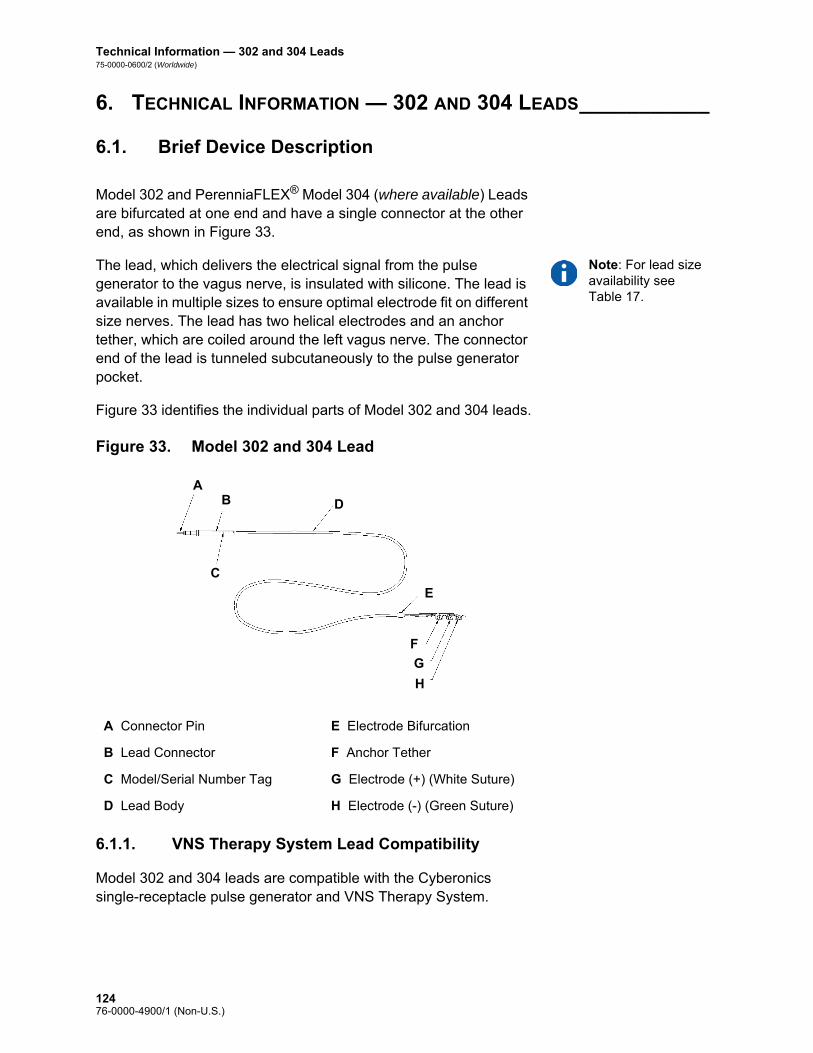
Technical Information — 302 and 304 Leads75-0000-0600/2 (Worldwide)
6. TECHNICAL INFORMATION — 302 AND 304 LEADS___________
6.1. Brief Device Description
Model 302 and PerenniaFLEX® Model 304 (where available) Leads are bifurcated at one end and have a single connector at the other end, as shown in Figure 33.
Note: For lead size availability see Table 17.
The lead, which delivers the electrical signal from the pulse generator to the vagus nerve, is insulated with silicone. The lead is available in multiple sizes to ensure optimal electrode fit on different size nerves. The lead has two helical electrodes and an anchor tether, which are coiled around the left vagus nerve. The connector end of the lead is tunneled subcutaneously to the pulse generator pocket.
Figure 33 identifies the individual parts of Model 302 and 304 leads.
Figure 33. Model 302 and 304 Lead
6.1.1. VNS Therapy System Lead Compatibility
Model 302 and 304 leads are compatible with the Cyberonics single-receptacle pulse generator and VNS Therapy System.
A Connector Pin E Electrode Bifurcation
B Lead Connector F Anchor Tether
C Model/Serial Number Tag G Electrode (+) (White Suture)
D Lead Body H Electrode (-) (Green Suture)
A
G
H
F
C
B D
E
12476-0000-4900/1 (Non-U.S.)

Technical Information — 302 and 304 Leads75-0000-0600/2 (Worldwide)
6.2. Device Operation
6.2.1. Product Specifications
Product information for the lead is presented in Table 17:
Note: All dimensions are nominal.
Table 17. Product Specifications
Lead Connector
Diameter 3.2 mm (0.127 in)
Material Silicone*
Connector Pin
Diameter 1.27 mm (0.05 in)
Material 300 series Stainless Steel
Connector Ring
Diameter 2.67 mm (0.105 in)
Material 300 series Stainless Steel
Lead Body
Diameter 2 mm (0.08 in)
Insulation Silicone*
Conductor coil construction Helical, quadfilar
Conductor material MP-35N alloy
Overall length 43 cm (17 in)
Lead resistance 120 to 180 Ohms (connector pin/ring to electrode)
Electrodes and Anchor Tether
Helical material Silicone elastomer*
Conductor material Platinum/Iridium Alloy
Separation 8 mm (0.31 in) center to center
Suture material Polyester
Inner Diameter of Helix
Model 302-20 2 mm (0.08 in) inner diameter
Model 302-30 3 mm (0.12 in) inner diameter
Model 304-20 2 mm (0.08 in) inner diameter
Model 304-30 3 mm (0.12 in) inner diameter
12576-0000-4900/1 (Non-U.S.)

Technical Information — 302 and 304 Leads75-0000-0600/2 (Worldwide)
Integrity information about the lead can be obtained using the Cyberonics programming wand, programming software, and a compatible computer. The software includes a System Diagnostics (Lead Test) feature that can be used to assess lead impedance.
6.2.2. Lead Lifespan and Replacement
Caution: Lead replacement or removal due to lack of efficacy is a medical judgement based on the patient’s desires and health status, and must be carefully weighed against the known and unknown risks of surgery. At present, there are no known long-term hazards or risks associated with leaving the lead implanted, beyond those already mentioned in this physician’s manual.
The lead’s lifespan is undetermined at this time. A lead would require replacement if a lead fracture were suspected, accompanied by increased symptoms (i.e., seizure frequency). Events that can shorten the life expectancy of the lead are as follows: Blunt trauma to the neck and/or any area of the body beneath
which the lead is implanted
Patient’s twisting or picking at either the implanted lead or pulse generator
Improper surgical implantation of the VNS Therapy System, including (but not limited to) providing an inadequate strain relief loop, placing sutures directly on the lead body, not using the tie-downs, and suturing to muscle
Tie-downs
Dimensions 5.7 mm X 7.7 mm (0.22 in x 0.30 in)
Material Radiopaque silicone*
Connector Assembly
One (1) Lead connector
Connector Retention Strength
With VNS Therapy pulse generator > 10 N
* No component of the VNS Therapy System is made with natural rubber latex.
12676-0000-4900/1 (Non-U.S.)

Technical Informaton—303 Lead
PerenniaDURA®—Model 303
12776-0000-4900/1 (Non-U.S.)

Technical Information — Model 303 Lead75-0000-0700/2 (Worldwide)
7. TECHNICAL INFORMATION — MODEL 303 LEAD_____________
7.1. Brief Device Description
The VNS Therapy PerenniaDURA® Model 303 Lead is bifurcated at one end and has a single connector pin at the other end, as shown in Figure 34.
The Lead, which delivers the electrical signal from the pulse generator to the vagus nerve, is insulated with silicone. The lead is available in two sizes (2.0 and 3.0 mm electrode inner diameter) to ensure optimal electrode fit on different size nerves. The lead has two helical electrodes and an anchor tether, which are coiled around the left vagus nerve. The connector end of the lead is tunneled subcutaneously to the pulse generator pocket. Figure 34 identifies the individual parts of the Model 303 lead.
Figure 34. Model 303 Lead
7.1.1. VNS Therapy System Lead Compatibility
The Model 303 lead is compatible with the Cyberonics single-receptacle pulse generator and the VNS Therapy System.
A Connector Pin E Anchor Tether
B Lead Connector F Electrode (+) (White Suture)
C Model/Serial Number Tag G Electrode (-) (Green Suture)
D Lead Body
A
F
G
E
C
BD
12876-0000-4900/1 (Non-U.S.)

Technical Informaton—303 Lead75-0000-0700/2 (Worldwide)
7.2. Device Operation
7.2.1. Product Specifications
Note: All dimensions are nominal.
Table 18. Model 303 Lead Product Specifications
Lead Connector:
Diameter 3.2 mm (0.127 in)
Material Silicone*
Connector Pin:
Diameter 1.27 mm (0.05 in)
Material 300 series Stainless Steel
Connector Ring:
Diameter 2.67 mm (0.105 in)
Material 300 series Stainless Steel
Lead Body:
Diameter 2 mm (0.08 in)
Insulation Silicone*
Conductor coil construction Helical, trifilar
Conductor material MP-35N alloy
Overall length 43 cm (17 in)
Lead resistance 180 to 250 Ohms (connector pin/ring to electrode)
Electrodes and Anchor Tether:
Helical material Silicone elastomer*
Conductor material Platinum/Iridium alloy
Separation 8 mm (0.31 in) center to center
Suture material Polyester
Inner Diameter of Helix:
Model 303-20 2 mm (0.08 in) inner diameter
Model 303-30 3 mm (0.12 in) inner diameter
Tie-downs:
Dimensions 5.7 mm x 7.7 mm (0.22 in x .30 in)
Material Radiopaque silicone*
12976-0000-4900/1 (Non-U.S.)

Technical Information — Model 303 Lead75-0000-0700/2 (Worldwide)
Integrity information about the lead can be obtained using the Cyberonics programming wand, programming software, and a compatible computer. The software includes a System Diagnostics (Lead Test) feature that can be used to assess lead impedance.
7.2.2. Lead Lifespan and Replacement
Caution: Lead replacement or removal due to lack of efficacy is a medical judgement based on the patient’s desires and health status, and must be carefully weighed against the known and unknown risks of surgery. At present, there are no known long-term hazards or risks associated with leaving the lead implanted, beyond those already mentioned in this physician’s manual.
The lead’s lifespan is undetermined at this time. A lead would require replacement if a lead fracture were suspected, accompanied by increased symptoms (i.e., seizure frequency). Events that can shorten the life expectancy of the lead are as follows: Blunt trauma to the neck and/or any area of the body beneath
which the lead is implanted
Patient’s twisting or picking at either the implanted lead or pulse generator
Improper surgical implantation of the VNS Therapy System, including (but not limited to) providing an inadequate strain relief loop, placing sutures directly on the lead body, not using the tie-downs, and suturing to muscle
Connector Assembly:
One (1) Lead connector
Connector Retention Strength:
With VNS Therapy pulse generator
> 10 N
* No component of the VNS Therapy System is made with natural rubber latex.
13076-0000-4900/1 (Non-U.S.)

Troubleshooting
Generator Models 102, 102R, 103, 104, 105, and 106
13176-0000-4900/1 (Non-U.S.)

Troubleshooting75-0000-2300/1 (Non-US)
8. TROUBLESHOOTING__________________________________
8.1. Model 102 and 102R
8.1.1. “Patient Cannot Feel Stimulation” at follow-up visit (Models 102-102R)
A patient may not feel stimulation if any of the following situations exist:
Patient has become accustomed to the programmed setting
Device is approaching its end of service (EOS)
“High” lead impedance
Short-circuit condition within the lead
Pulse generator issue
To determine the cause of the situation, perform the following steps:Note: Ensure that the technique for swiping the magnet over the device is correct according to the section “Initiating stimulation with a magnet” in the102/102R Technical Information chapter. Also see “Potential Adverse Events” in the indication-specific information chapters for a complete list of possible adverse events.
1. Swipe the magnet. Ask the patient if they feel the magnet activation, experience any voice alteration, or experience any other common side effect to indicate the presence of stimulation.
2. Interrogate the pulse generator.
13276-0000-4900/1 (Non-U.S.)
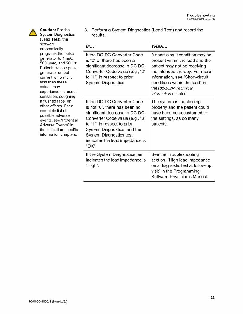
Troubleshooting75-0000-2300/1 (Non-US)
Caution: For the System Diagnostics (Lead Test), the software automatically programs the pulse generator to 1 mA, 500 μsec, and 20 Hz. Patients whose pulse generator output current is normally less than these values may experience increased sensation, coughing, a flushed face, or other effects. For a complete list of possible adverse events, see “Potential Adverse Events” in the indication-specific information chapters.
3. Perform a System Diagnostics (Lead Test) and record the results.
IF… THEN…
If the DC-DC Converter Code is “0” or there has been a significant decrease in DC-DC Converter Code value (e.g., “3” to “1”) in respect to prior System Diagnostics
A short-circuit condition may be present within the lead and the patient may not be receiving the intended therapy. For more information, see “Short-circuit conditions within the lead” in the102/102R Technical Information chapter.
If the DC-DC Converter Code is not “0”, there has been no significant decrease in DC-DC Converter Code value (e.g., “3” to “1”) in respect to prior System Diagnostics, and the System Diagnostics test indicates the lead impedance is “OK”
The system is functioning properly and the patient could have become accustomed to the settings, as do many patients.
If the System Diagnostics test indicates the lead impedance is “High”.
See the Troubleshooting section, “High lead impedance on a diagnostic test at follow-up visit” in the Programming Software Physician’s Manual.
133 76-0000-4900/1 (Non-U.S.)

Troubleshooting75-0000-2300/1 (Non-US)
4. Perform a Normal Mode Diagnostics test and record the results.
5. If further assistance is needed, call Cyberonics at 1 (866) 882-8804 (U.S. and Canada), +1 (281) 228-7330 (Worldwide), or +32 2 790 27 73 (Europe/EMMEA).
8.1.2. Magnet activation not working at follow-up visit (Models 102-102R)
A patient’s magnet activation may not be working if any of the following situations exist:
Patient may have become accustomed to the programmed setting.
An incorrect technique is used for swiping the magnet.
Magnet output current is not programmed to ON.
Device is approaching its end of service (EOS).
Device was implanted too deep.
There is an issue with the pulse generator.
“High” lead impedance.
Short-circuit condition within the lead.
IF… THEN…
The Normal Mode Diagnostics test indicates the Output Current is “LIMIT”
The pulse generator cannot deliver programmed output. Consider reducing output current or frequency and widening the pulse width.
The Normal Mode Diagnostics test indicates the Output Current is “OK”
The pulse generator can deliver the programmed output current.
Note: To obtain accurate information from the device diagnostics, the pulse generator must be programmed to a minimum of 0.75 mA, 15 Hz, and at least 30 seconds ON time.
The Normal Mode Diagnostics test indicates “HIGH” lead impedance
See the Troubleshooting section, “High lead impedance on a diagnostic test at follow-up visit” in the Programming Software Physician’s Manual.
13476-0000-4900/1 (Non-U.S.)

Troubleshooting75-0000-2300/1 (Non-US)
To determine the cause of the situation, perform the following steps:
1. Interrogate the device.
2. Confirm that the Magnet Output Current is ≥ 0.25 mA and Magnet ON time is > 7 seconds.
3. Display the Device History screen and record the number of magnet activations listed on the screen.
Note: Ensure that the technique for swiping the magnet over the device is correct according to the section “Initiating stimulation with a magnet” 102/102R Technical Information chapter.
Note: Follow the listed instructions and swipe the magnet just before starting the test. To obtain accurate information from the device diagnostics, the pulse generator must be programmed to a minimum of 0.75 mA (Magnet Output Current), 15 Hz (Normal Mode Frequency), and 30 seconds (Magnet ON Time).
4. Swipe the magnet over the device and watch for a clinical response to the stimulation. Wait 3 to 4 minutes and re-interrogate the device.
5. Display the Device History screen and record the number of magnet activations listed on that screen. The number of activations should have increased by 1.
6. If the magnet activation shows up on the Magnet History screen but the patient does not feel magnet-induced stimulation, increase the magnet output current until the magnet-induced stimulation is felt.
7. If the number of magnet activations did not increase, go to the Device Diagnostics screen and perform a Magnet Mode Diagnostics test and record all results.
8. If further assistance is needed, call Cyberonics at 1 (866) 882-8804 (U.S. and Canada), +1 (281) 228-7330 (Worldwide), or +32 2 790 27 73 (Europe/EMMEA).
IF… THEN…
The Magnet Mode Diagnostics test indicates device status “MAGNET MODE” and output current is “OK”
The magnet is functioning properly and the patient could have become accustomed to the settings, as do many patients.
The Magnet Mode Diagnostics test indicates device status “STANDBY” and output current “****”
Perform steps 1 through 7 with an alternate Cyberonics magnet.
The Magnet Mode Diagnostics test indicates “HIGH” lead impedance
See the Troubleshooting section, “High lead impedance on a diagnostic test at follow-up visit” in the Programming Software Physician’s Manual.
135 76-0000-4900/1 (Non-U.S.)

Troubleshooting75-0000-2300/1 (Non-US)
8.2. Model 103, 104, 105 and 106
8.2.1. Patient cannot feel stimulation” at follow-up visit (Models 103-106)
A patient may not feel stimulation under any of these conditions:
Patient has become accustomed to the programmed setting
Pulse generator battery at end of service (EOS)
“High” lead impedance
Defective pulse generator
Disabled pulse generator
Short-circuit condition within the lead
To determine the cause of the condition, perform these steps (see Figure 35):
1. Interrogate the pulse generator.
Note: If the CAUSE is “a wand reset” and the reset was intended, continue with the session.
If the following message appears, call Cyberonics: “The pulse generator is currently disabled due to [CAUSE]. Note that the generator is NOT supplying stimulation. It is recommended that you contact Cyberonics or refer to the Physician’s Manual.”
2. Perform a System Diagnostics and record the results.
If the output current reports “OK” and lead impedance reports “OK,” then the pulse generator is able to deliver the programmed therapy and the patient may have become accustomed to the stimulation, as do many patients.
If the output current reports “OK” and lead impedance reports “LOW” (≤ 600 Ohms), then there is a possibility of a short-circuit condition within the lead. See the troubleshooting section “High lead impedance, low lead impedance, or low output current on a diagnostic test at follow-up visit” in the Programming Software Physician’s Manual.
If the output current reports “LOW” and lead impedance reports “OK,” then the pulse generator cannot deliver programmed output due to increased impedance. Consider lowering the output current while increasing pulse width.
If the output current reports “LOW” and lead impedance reports “HIGH” (≥ 5300 Ohms), see the troubleshooting section “High lead impedance on a diagnostic test at follow-up visit” in the Programming Software Physician’s Manual.
13676-0000-4900/1 (Non-U.S.)

Troubleshooting75-0000-2300/1 (Non-US)
3. For further assistance, call Cyberonics at 1 (866) 882-8804 (U.S. and Canada), +1 (281) 228-7330 (Worldwide), or +32 2 790 27 73 (Europe/EMMEA).
Figure 35. “Patient Cannot Feel Stimulation” at Follow-Up Visit (Models 103-106)
Record the CAUSE
Patient Report:“Cannot feel stimulation”
Perform a System Diagnostics.Record results.
Lead Impedance Result
The pulse generator cannot deliver programmed output. Consider lowering output current while increasing pulse width.
“HIGH” or “LOW”
“LOW” “OK”
Output Current Result For possible causes, see the Troubleshooting section “High lead impedance on a diagnostic test at follow-up visit” in the Programming Software Physician’s Manual.
“OK”
Contact Cyberonics’ Clinical Technical Support at:1 (866) 882-8804 (U.S. and Canada)+1 (281) 228-7330 (Worldwide)+32 2 790 27 73 (Europe/EMMEA)
The pulse generator is able to deliver programmed output current and the VNS system is working properly.
Probable Diagnosis:The patient has grown accustomed to stimulation but is still receiving the programmed therapy.
“The pulse generator is currently disabled due to [CAUSE]. Note that the generator is NOT supplying stimulation. It is recommended that you contact Cyberonics or refer to the Physician’s Manual”
Note: If the CAUSE is “a wand reset” and the reset was intended, continue with the session.
Interrogate the pulse generator
No “Disabled” Message
“Disabled” Message
137 76-0000-4900/1 (Non-U.S.)

Troubleshooting75-0000-2300/1 (Non-US)
8.2.2. “Patient cannot feel magnet activation” at follow-up visit (Models 103-106)
Magnet activation may not be perceived under any of these conditions:
Patient has become accustomed to the programmed setting
Incorrect technique for swiping magnet
Magnet output current is programmed to 0 mA
Pulse generator battery at end of service (EOS)
Device implanted too deep in the chest
Defective pulse generator
Disabled pulse generator
“High” lead impedance
Short-circuit condition within the lead
To determine the cause of the condition, perform these steps (see Figure 36):
1. Interrogate the device.Note: If the CAUSE is “a wand reset” and the reset was intended, continue with the session.
If the following message appears, call Cyberonics: “The pulse generator is currently disabled due to [CAUSE]. Note that the generator is NOT supplying stimulation. It is recommended that you contact Cyberonics or refer to the Physician’s Manual.”
2. Confirm that the magnet output current is ≥ the Normal output current and magnet ON time is > 7 seconds.
3. Select MENU on the top right-hand corner of the screen, and then select DISPLAY DEVICE HISTORY. Record the number of magnet activations listed on the screen.
Note: Ensure that the technique for swiping the magnet over the device is correct. (See “VNS Therapy magnets” in the 103/104, 105, and 106 Technical Information chapters.)
The number of magnet activations may increase by 1 or 2 with the cross-pattern swipe technique.
4. Swipe the magnet over the device.
5. Reinterrogate the device.
6. Select MENU on the top right-hand corner, and then select DISPLAY DEVICE HISTORY. Record the number of magnet activations listed on that screen. The number of magnet activations should have increased.
If the number of magnet activations increased, the pulse generator is delivering the magnet stimulation. Consider raising the magnet current if perceived stimulation is desired.
If the number of magnet activations did not increase with the test swipe, select MENU and go to the DEVICE DIAGNOSTICS screen. From this screen, select OTHER DIAGNOSTICS, and then perform a Magnet Mode Diagnostics. Record all results.
13876-0000-4900/1 (Non-U.S.)

Troubleshooting75-0000-2300/1 (Non-US)
Note: Follow the listed instructions and swipe the magnet just before starting the test.
a. If the pulse generator did not sense a magnet swipe, then you will receive a warning. Swipe the magnet again and repeat Magnet Mode Diagnostics. If the warning appears again, call Cyberonics at 1 (866) 882-8804 (U.S. and Canada), +1 (281) 228-7330 (Worldwide), or +32 2 790 27 73 (Europe/EMMEA).
b. If the output current reports “OK” and lead impedance reports “OK,” then the Magnet Mode stimulation is functioning properly and the patient may have become accustomed to the settings.
c. If the output current reports “LOW” and lead impedance reports “OK,” then the pulse generator cannot deliver the programmed magnet output due to increased impedance. Consider lowering the magnet output current while increasing the magnet pulse width.
d. If the output current reports “LOW” and lead impedance reports “HIGH,” see “Patient cannot feel stimulation” at follow-up visit (Models 103-106)”.
7. For further assistance, call Cyberonics at 1 (866) 882-8804 (U.S. and Canada), +1 (281) 228-7330 (Worldwide), or +32 2 790 27 73 (Europe/EMMEA).
139 76-0000-4900/1 (Non-U.S.)

Troubleshooting75-0000-2300/1 (Non-US)
Figure 36. “Patient Cannot Feel Magnet Activation” at Follow-Up Visit (Models 103-106)
Record the CAUSE
Patient Report:“Cannot feel magnet activation”
Interrogate the device
Lead Impedance “OK”Output Current “OK”
Magnet Mode stimulation is functioning properly and the patient may have become accustomed to the settings. Consider raising the magnet current if perceived stimulation is desired.
No
Display Device History.Record number of magnet activations.Swipe the magnet.Reinterrogate the device.Display Device History.Did the magnet activations increase?
Generator is delivering the magnet stimulation. Consider raising the magnet current if perceived stimulation is desired.
Contact Cyberonics’ Clinical Technical Support at:1 (866) 882-8804 (U.S. and Canada)+1 (281) 228-7330 (Worldwide)+32 2 790 27 73 (Europe/EMMEA)
Lead Impedance “HIGH” or “LOW”
See the Troubleshooting section “High lead impedance, Low lead impedance, or Low output current on a Diagnostic Test at follow-up visit.” in the Programming Software Physician’s Manual.
Is Magnet Current > the Output Current?and
Is Magnet ON time > 7 seconds?
Magnet settings may be too low for patient to perceive. Consider adjusting magnet setting.
Yes
1. Perform a Magnet Mode Diagnostic.
2. Record results.
No
“Warning! The pulse generator did not sense a magnet swipe…"
Swipe the magnet again and repeat Magnet Mode Diagnostics. If the warning appears again call Cyberonics
Lead Impedance “OK”Output Current “LOW”
Pulse generator cannot deliver the programmed magnet output due to increased impedance. Consider lowering magnet output current while increasing magnet pulse width.
Yes
“Disabled” Message
“The pulse generator is currently disabled due to [CAUSE]. Note that the generator is NOT supplying stimulation. It is recommended that you contact Cyberonics or refer to the Physician’s Manual”
Note: If the CAUSE is “a wand reset” and the reset was intended, continue with the session.
No “Disabled” Message
14076-0000-4900/1 (Non-U.S.)

Troubleshooting75-0000-2300/1 (Non-US)
8.2.3. Patient Does Not Perceive AutoStim Activation or Seizure Detection Inaccurate at Follow-up (Model 106 Only)
AutoStim activation may not be perceived under any of these conditions:
Threshold for AutoStim setting is too low
Patient has become accustomed to the programmed setting
AutoStim output current is programmed to 0 mA
Pulse generator battery at end of service (EOS)
Defective pulse generator or lead
Disabled pulse generator
Seizure Detection may be inaccurate due to the following reasons:
Threshold for AutoStim setting is not optimized
Duty Cycle: Normal Mode OFF-time may be too short. Longer OFF-times allow for more detection.
Exercise, physical activity, or normal fluctuations in heart rate during sleep may result in false detection and unintended stimulation.
For either AutoStim activation not perceived or Seizure Detection Inaccurate (Under detecting), perform these steps:
1. Ensure the programming computer is unplugged and Interrogate the device.
Note: If the CAUSE is “a wand reset” and the reset was intended, continue with the session.
If the following message appears, call Cyberonics: “The pulse generator is currently disabled due to [CAUSE]. Note that the generator is NOT supplying stimulation. It is recommended that you contact Cyberonics or refer to the Physician's Manual.”
2. Confirm that Seizure Detection is “ON” and the AutoStim output current is set to a value > 0 mA and ≥ the Normal output current.
3. Confirm heartbeat detection (See “Troubleshooting at Follow-up Visits” in the Programming Software Physician’s Manual.)
4. Perform AutoStim Diagnostics from the Device Diagnostics Menu.
If the diagnostics indicates that the AutoStim output current was delivered, re-evaluate at the next office visit:
5. Select MENU on the top right-hand corner of the screen, and then select DISPLAY DEVICE HISTORY. Select “O.V.” for Office Visit data and investigate consecutive office visits to identify any changes in the average number of AutoStims per day delivered by the device.
141 76-0000-4900/1 (Non-U.S.)

Troubleshooting75-0000-2300/1 (Non-US)
6. Make note of the average number of AutoStims per day since the last visit.
If the average number of AutoStim per day is > 0, the pulse generator is delivering the AutoStim stimulation as detected by the algorithm. Consider raising the AutoStim current if perceived stimulation is desired.
If the average number of AutoStim activations per day since last office visit is 0 and the patient has had seizures during this period, continue to adjust the Threshold for AutoStim setting (toward 20%) after assessing at each visit until patient perceives stimulation or the device confirms the logging of events.
For Seizure Detection Inaccurate (Under/Over Detection) follow these general steps (See Figure 37):
1. Ensure the programming computer is unplugged.
2. Interrogate the device
3. On the “Seizure Detection” tab, ensure Seizure Detection is “ON”
4. Confirm heartbeat detection is configured properly (“Heartbeat Over/Under Detection”)
5. Assess Threshold for AutoStim setting:
If the device is not detecting seizures that are known to have occurred (i.e. under-detecting seizures), adjust the Threshold for AutoStim setting toward 20%.
If the device is detecting more events than desired (i.e. over detecting), adjust the Threshold for AutoStim setting toward 70%.
6. Monitor the device's declaration of seizures carefully over the course of the therapy for future adjustments.
7. For further assistance, call Cyberonics at 1 (866) 882-8804 (U.S. and Canada), +1 (281) 228-7330 (Worldwide), or +32 2 790 27 73 (Europe/EMMEA).
14276-0000-4900/1 (Non-U.S.)

Troubleshooting75-0000-2300/1 (Non-US)
Figure 37. Patient Cannot Feel AutoStim Activation or Seizure Detection Inaccurate at Follow-up (Model 106 Only)
For directions on how to confirm heartbeat detection see Heartbeat Over/Under Detection in the Technical Information—106 Generator chapter of this manual or refer to the Programming Software Physician’s Manual.
Seizure Detection feature results in inaccurate declarations of seizures (i.e. Over-counting or Under-counting seizures)
Ensure programming computer is unplugged from wall outlet.Ensure Seizure Detection is set to “ON”.Confirm Heartbeat Detection.
Adjust Threshold for AutoStim setting toward 20%
Adjust Threshold for AutoStim setting toward 70%
Monitor accuracy over course of therapy
The following may affect the accuracy of detecting seizures:Duty cycle: Detection can only occur during the Normal Mode “OFF-time”; therefore shorter OFF-times reduce the devices ability to detect seizures, while longer OFF-times allow for more detection time.Exercise or physical activity that causes an increase in heart rate resulting in falsely declared seizures.Normal heart rate changes that occur during sleep may result in falsely declared seizures.
Over-counting seizures Under-counting seizures
143 76-0000-4900/1 (Non-U.S.)

Troubleshooting75-0000-2300/1 (Non-US)
14476-0000-4900/1 (Non-U.S.)

Depression Information
VNS Therapy® System
14576-0000-4900/1 (Non-U.S.)

Depression Information75-0000-1000/0 (Non-U.S.)
9. DEPRESSION INFORMATION ____________________________
9.1. Clinical Studies—Safety
Note: For intended use/indications, see the Introduction to the VNS Therapy System chapter.
Except where noted otherwise, the safety information presented in this section derives from the pivotal (D-02) study. The D-02 study of VNS Therapy consisted of both an acute and a long-term phase to collect data regarding the safety and efficacy of VNS Therapy as an adjunctive treatment for persons with chronic or recurrent treatment-resistant depression.
9.1.1. Device Performance
The VNS Therapy System performed according to its specifications. Most device issues were communication difficulties resolved by repositioning the Programming Wand or replacing the Programming Wand batteries. One high lead impedance occurred requiring replacement; a lead break due to fatigue at the electrode bifurcation was noted. Most device complaints were resolved on the day of initial complaint.
9.1.2. Adverse Events
The number (and percentage) of subjects reporting an adverse event during the 0-3 month period and during the 9-12 month period of the pivotal (D-02) study is depicted in Table 19 for the most commonly reported adverse events. Adverse events were coded using the COSTART 5 dictionary. Note that some subjects may have reported multiple events.
Table 19. Adverse Events Reported During VNS Therapy at 0-3 Months and 9-12 Months (D-02)
Adverse Event0-3 Months
(N=232)9-12 Months
(N=209)
Voice Alteration 135 (58.2%) 113 (54.1%)
Increased Cough 55 (23.7%) 13 (6.2%)
Neck Pain 38 (16.4%) 27 (12.9%)
Dyspnea 33 (14.2%) 34 (16.3%)
Dysphagia 31 (13.4%) 9 (4.3%)
Paresthesia 26 (11.2%) 9 (4.3%)
14676-0000-4900/1 (Non-U.S.)

Depression Information75-0000-1000/0 (Non-U.S.)
It is important to note that subjects often had comorbid illnesses and almost all study subjects were also receiving antidepressant and other drugs that could have contributed to these events.
9.1.2.1. Discontinuation due to adverse events
In the feasibility (D-01) study, no discontinuations were related to adverse events attributed to VNS Therapy or the implant procedure. By the time all continuing subjects in the pivotal (D-02) study had at least 1 year of VNS Therapy, 3% (8/235) of the subjects had discontinued VNS Therapy for an adverse event-related reason. The reasons for these eight discontinuations included one case each of suicide, implant-related infection necessitating device removal, hoarseness, lightheadedness, post-operative pain, chest and arm pain, sudden death (of unknown cause), and worsening
Laryngismus 23 (9.9%) 10 (4.8%)
Pharyngitis 14 (6.0%) 11 (5.3%)
Nausea 13 (5.6%) 4 (1.9%)
Pain 13 (5.6%) 13 (6.2%)
Headache 12 (5.2%) 8 (3.8%)
Insomnia 10 (4.3%) 2 (1.0%)
Palpitation 9 (3.9%) 6 (2.9%)
Chest Pain 9 (3.9%) 4 (1.9%)
Dyspepsia 8 (3.4%) 4 (1.9%)
Hypertonia 6 (2.6%) 10 (4.8%)
Hypesthesia 6 (2.6%) 2 (1.0%)
Anxiety 5 (2.2%) 6 (2.9%)
Ear Pain 5 (2.2%) 6 (2.9%)
Eructation 4 (1.7%) 0
Diarrhea 4 (1.7%) 2 (1.0%)
Dizziness 4 (1.7%) 3 (1.4%)
Incision Site Reaction 4 (1.7%) 2 (1.0%)
Asthma 4 (1.7%) 3 (1.4%)
Device Site Reaction 4 (1.7%) 0
Device Site Pain 4 (1.7%) 2 (1.0%)
Migraine Headache 4 (1.7%) 2 (1.0%)
Adverse Event0-3 Months
(N=232)9-12 Months
(N=209)
14776-0000-4900/1 (Non-U.S.)

Depression Information75-0000-1000/0 (Non-U.S.)
depression (reported by the investigator as an adverse event rather than as lack of efficacy).
9.1.3. Serious Adverse Events (SAEs)
9.1.3.1. SAEs
The SAEs described in this section are based on investigator reports from the pivotal (D-02) study from study initiation through the data cutoff date for submission; the data cutoff date included the entire period of evaluation for subjects who did not complete 12 months of VNS Therapy and included a minimum of 12 months of evaluation during VNS Therapy for all subjects who continued the study for 12 months or longer.
During the pivotal (D-02) study, 12 SAEs were considered related to the implant procedure (wound infection, asystole, bradycardia, syncope, abnormal thinking, vocal cord paralysis, aspiration pneumonia, voice alteration, device site reaction [two reports], acute renal failure, and urinary retention). During the acute phase of the D-02 study, investigators did not report any SAE to be related to stimulation. During the long-term phase of the D-02 study, eight SAEs were considered at least possibly related to stimulation (sudden death of unknown cause, syncope (two reports), dizziness, a manic depressive reaction in a subject with bipolar disorder, hemorrhage GI, paresthesia, and an incident of worsening depression. Table 20 displays all the SAEs reported during the D-02 study prior to the data cutoff date, regardless of relationship to implantation or stimulation.
Table 20. Serious Adverse Events Reported in Study D-02, Regardless of Relationship to Implantation or Stimulation
Event
Acute (N=235) Long Term (N=233)
Number of Events
Treatment (N=119) /Sham
(N=116)
Number of
Subjects
Number of
Events
Number of
Subjects
Worsening Depression 5/7 11 62 31
Suicide Attempt 0 0 7 6
Syncope 0 0 4 3
Dehydration 1/1 2 1 1
14876-0000-4900/1 (Non-U.S.)

Depression Information75-0000-1000/0 (Non-U.S.)
Wound Infection 1/0 1 1 1
Cholecystitis 0/1 1 1 1
Gastrointestinal Disorder 0 0 2 2
Abnormal Thinking 1/0 1 1 1
Convulsion 0 0 2 2
Device Site Reaction 2/0 2 0 0
Pneumonia 0/1 1 0 0
Abdominal Pain 0 0 1 1
Accidental Injury 0 0 1 1
Chest Pain 0 0 1 1
Overdose 0 0 1 1
Peritonitis 0 0 1 1
Sudden Unexplained Death
0 0 1 1
Suicide 1/0 1 0 0
Surgical Procedure 0 0 1 1
Asystole 1/0 1 0 0
Bradycardia 1/0 1 0 0
Cholelithiasis 0 0 1 1
Constipation 0 0 1 1
Myasthenia 0/1 1 0 0
Confusion 1/0 1 0 0
Dizziness 0 0 1 1
Drug Dependence 0 0 1 1
Manic Depression 0 0 1 1
Somnolence 0 0 1 1
Vocal Cord Paralysis 0/1 1 0 0
Breast Cancer 0 0 1 1
Aspiration Pneumonia 1/0 1 0 0
Event
Acute (N=235) Long Term (N=233)
Number of Events
Treatment (N=119) /Sham
(N=116)
Number of
Subjects
Number of
Events
Number of
Subjects
14976-0000-4900/1 (Non-U.S.)

Depression Information75-0000-1000/0 (Non-U.S.)
9.1.3.2. Deaths
Four deaths occurred during the pivotal (D-02) study: one after the subject had given consent, but before the subject was implanted; the second, a suicide; the third, a death of unknown cause; and the fourth, a subject who developed multi-organ failure.
9.1.3.3. Unanticipated adverse device effects
Two events in the pivotal (D-02) study met criteria for an unanticipated adverse device effect (UADE)—see the Glossary for definition. Both these events were non-specific complications of surgery related to the implant procedure and occurred before stimulation began. One UADE was an episode of acute renal failure thought to be secondary to antibiotic administration, and the other was an episode of altered mental status thought to be due to perioperative narcotic administration.
9.1.4. Safety Considerations Specific to Depressed Patients
Two specific safety concerns in the use of all antidepressant therapies are the precipitation of manic or hypomanic episodes and the possible effect of antidepressant therapy on suicidal ideation and behavior.
9.1.4.1. Antidepressant treatments and manic or hypomanic reaction
Although patients with bipolar disorder experience manic episodes as the cardinal feature of their disorder, effective antidepressant therapies themselves can occasionally precipitate a manic or hypomanic episode. Antidepressant therapies can also occasionally precipitate a manic or hypomanic episode in patients without a prior
Voice Alteration 0/1 1 0 0
Acute Renal Failure 0/1 1 0 0
Enlarged Uterine Fibroid 0 0 1 1
Urinary Retention 1/0 1 0 0
Event
Acute (N=235) Long Term (N=233)
Number of Events
Treatment (N=119) /Sham
(N=116)
Number of
Subjects
Number of
Events
Number of
Subjects
15076-0000-4900/1 (Non-U.S.)

Depression Information75-0000-1000/0 (Non-U.S.)
history of mania who are being treated for a major depressive episode.
9.1.4.1.1. Manic reactions
In the pivotal (D-02) study, six hypomanic or manic reactions were identified according to DSM IV criteria or the Young Mania Rating Scale (YMRS). Five were observed in subjects with a known history of prior hypomanic or manic episodes. One of the events was considered serious and the subject was hospitalized.
9.1.4.2. Suicidal ideation, suicide attempts, suicide, and worsened depression
Suicidal ideation was analyzed by examining the HRSD24 Item 3
scores. At 12 months of VNS Therapy, 90% of the subjects in the pivotal (D-02) study showed either improvement (56%) or no change (34%) in their Item 3 scores. During the acute D-02 study, 2.6% of the sham subjects and 1.7% of the stimulation subjects increased their Item 3 score by 2 or more points, indicative of an increase in suicidal ideation. During the long-term D-02 phase, 2.8% of the subjects had an increase in their Item 3 score by at least 2 points at 12 months compared to baseline. In a non-randomized control group of subjects treated with standard antidepressant therapies without VNS Therapy (the D-04 study population), 1.9% of the subjects had an increase of at least 2 points. Based on the occurrence of any increase in Item 3 score from baseline to 12 months, 10% of the D-02 subjects had an increase compared to 11% of the D-04 population. Conversely, 27% of the D-02 subjects decreased their score by at least 2 points at 12 months compared to baseline, whereas only 9% of the D-04 subjects did.
Suicide attempts and completed suicides in the D-02 and D-04 studies are shown in Table 21. As noted above, one subject committed suicide in the acute phase and six attempted suicide during the long-term phase of the D-02 study (N = 235). One of the six subjects noted in the long-term phase attempted suicide twice. Although safety data were not prospectively collected for the D-04 study, the healthcare utilization form documented suicide attempts. Three suicide attempts were reported for the D-04 study through the first year of the study (N=124).
15176-0000-4900/1 (Non-U.S.)

Depression Information75-0000-1000/0 (Non-U.S.)
Table 21. Suicide Attempt and Suicide Rates
In the acute phase of the D-02 study, there were 12 reports of worsening depression, 5 in the stimulation group (5 of 119 subjects) and 7 in the sham group (7 of 116 subjects). One of the treatment-group reports occurred prior to stimulation initiation. Following acute phase exit and during the long-term phase of stimulation, 62 events were reported in 31 subjects. The number of episodes of worsening depression per subject ranged from 1 to 6. Although specific rates of worsening depression (and other safety endpoints) were not collected during the D-04 study, “hospitalizations for psychiatric illness,” which might be a reasonable surrogate for worsening depression, were recorded. The rate of this event was 0.237 events per patient-year in the D-04 group compared to 0.293 events of worsening depression per patient-year in the D-02 group.
9.1.5. Adverse Event (AE) Relationship to VNS Therapy and Duration of Events
The pivotal (D-02) study investigators determined whether an adverse event (AE) was possibly, probably, or definitely related to implantation of, or stimulation by, the VNS Therapy pulse generator and lead.
9.1.5.1. Adverse events related to implantation
Note: Although not seen as part of the pivotal (D-02) study, seroma formation is a potential implantation related adverse event.
Because all eligible study subjects in the pivotal (D-02) study were implanted with the VNS Therapy™ System device, no control was available to assess whether an adverse event was related to the surgery. Investigators, therefore, determined which adverse events were related to implantation. The events reported as related to implantation and occurring in at least 10% of the subjects who received VNS Therapy System implants in the pivotal (D-02) study were device site pain, device site reaction, incision pain, dysphagia, hypesthesia, pharyngitis, voice alteration, and incision site reaction. The complete list of implantation-related adverse events is shown in Table 22 and Table 23.
Number of
Patients
Patient Years
Suicide Attempts/
Patient Years
Suicide/ Patient Years
D-02 235 502 2.4% 0.2%
D-04 124 118 2.5% 0.0%
15276-0000-4900/1 (Non-U.S.)

Depression Information75-0000-1000/0 (Non-U.S.)
Table 22. Implantation-Related Adverse Events Occurring in Greater Than or Equal To 5% of Subjects During the Acute Phase of the Pivotal (D-02) Study
D-02 Acute Phase Incidence of Surgery-Related AEs
(n=235)
Body as a Whole
Incision Pain 36%
Device Site Pain 23%
Device Site Reaction 14%
Headache 8%
Neck Pain 7%
Pain 7%
Digestive System
Dysphagia 11%
Nausea 9%
Nervous System
Hypesthesia 11%
Paresthesia 6%
Respiratory System
Voice Alteration 33%
Pharyngitis 13%
Dyspnea 9%
Cough Increased 6%
Skin and Appendages
Incision Site Reaction 29%
15376-0000-4900/1 (Non-U.S.)

Depression Information75-0000-1000/0 (Non-U.S.)
Table 23. Implantation-Related Adverse Events Occurring in Less Than 5% of Subjects in Acute Phase - Pivotal (D-02) Study
Body as a Whole
Abdominal Pain, Allergic Reaction, Anaphylactic Reaction, Asthenia, Back Pain, Chest Pain, Chills, Fever, Infection, Injection Site Pain, Neck Rigidity, Photosensitivity Reaction, Surgical Injury, Viral Infection, Wound Infection
Cardiovascular System
Arrhythmia, Asystole, Bradycardia, Hemorrhage, Migraine, Palpitation, Syncope, Tachycardia
Digestive System
Anorexia, Constipation, Diarrhea, Dyspepsia, Flatulence, Gastrointestinal Disorder, Vomiting
Endocrine System
Thyroid Disorder
Hemic and Lymphatic System
Ecchymosis, Lymphadenopathy
Metabolic and Nutritional Disorders
Edema, Hyperglycemia, Peripheral Edema
Musculoskeletal
Arthralgia, Joint Disorder, Myalgia, Myasthenia
Nervous System
Abnormal Dreams, Agitation, Ataxia, Dizziness, Hypertonia, Insomnia, Nervousness, Neuralgia, Neuropathy, Thinking Abnormal, Tremor, Vasodilatation, Vocal Cord Paralysis
Respiratory System
Aspiration Pneumonia, Asthma, Atelectasis, Bronchitis, Hiccup, Hypoxia, Laryngismus, Laryngitis, Lung Disorder, Respiratory Disorder, Rhinitis, Sinusitis, Sputum Increased
Skin and Appendages
Application Site Reaction, Maculopapular Rash, Pruritus, Rash, Sweating
Special Senses
Ear Disorder, Ear Pain, Tinnitus
Urogenital
Acute Kidney Failure, Dysuria, Metrorrhagia, Urinary Retention
15476-0000-4900/1 (Non-U.S.)

Depression Information75-0000-1000/0 (Non-U.S.)
9.1.5.2. Duration of implant-related adverse events
As can be seen in Table 24, many of the individual incidences of the most common implantation-related AEs resolved within 30 days. Hypesthesia (generally described as a localized numbness) and voice alteration, however, tended to be more persistent in some individuals. For example, in 17 of 24 reports of implantation-related hypesthesia, the event continued beyond 3 months. Hypesthesia would be an expected side effect of nerve injury during surgery. The persistence of voice alteration in some subjects is difficult to assess because it could represent surgical injury to the innervation of the larynx, but vagus nerve stimulation itself can cause voice alteration.
Table 24. D-02 Acute Phase Duration of Treatment-Emergent Adverse Events Related to Implantation Reported by More Than 10% of Subjects
Body System
Preferred Term
Duration to Resolution of Event in Days by all Implanted Subjects
1 – 7Days
8 – 14Days
15 – 30Days
31 – 60Days
61-90Days
>90Days
Total N = 235 through 30 days, 234 for 31 to 90, 233 for >90 days
Number within each box indicates number of subjects whose event resolved within the days shown (i.e., 27 subjects had
the event of device site pain resolve within 7 days)
Body as a Whole
Device Site Pain 27 4 9 9 3 4
Device Site Reaction
5 5 8 9 2 8
Incision Pain 28 18 21 10 3 6
Digestive System
Dysphagia 2 5 9 5 2 5
Nervous System
Hypesthesia 0 0 3 2 2 17
Respiratory System
Pharyngitis 10 8 10 2 0 1
Voice Alteration 11 7 22 17 3 21
Skin and Appendages
Incision Site Reaction
19 16 24 16 2 14
15576-0000-4900/1 (Non-U.S.)

Depression Information75-0000-1000/0 (Non-U.S.)
9.1.5.3. Stimulation-related adverse events
Among AEs judged by investigators to be stimulation-related in the D-02 study acute phase treatment group, seven events occurred at a frequency of 10% or greater: voice alteration (55%), cough increased (24%), dyspnea (19%), neck pain (16%), dysphagia (13%), laryngismus (11%), and paresthesia (10%).
Table 25 and Table 26 list stimulation-related adverse events that occurred during the acute phase of the pivotal (D-02) study.
Table 25. Stimulation-Related Adverse Events Occurring in Greater Than or Equal To 5% of Subjects in Treatment Versus Control, Acute Phase - Pivotal (D-02) Study
D-02Treatment (n=119)
D-02 Sham-control* (n=116)
Body as a Whole
Incision Pain 6 (5%) 3 (3%)
Neck Pain 19 (16%) 1 (<1%)
Digestive System
Dysphagia 15 (13%) 0 (0%)
Nausea 8 (7%) 1 (<1%)
Nervous System
Paresthesia 12 (10%) 3 (3%)
Respiratory System
Cough Increased 28 (24%) 2 (2%)
Dyspnea 23 (19%) 2 (2%)
Laryngismus 13 (11%) 0 (0%)
Pharyngitis 9 (8%) 1 (<1%)
Voice Alteration 65 (55%) 3 (3%)
*Note: These subjects were not receiving stimulation during this phase.
15676-0000-4900/1 (Non-U.S.)

Depression Information75-0000-1000/0 (Non-U.S.)
Table 26. Stimulation-Related Adverse Events Occurring in Less Than 5% of Subjects in the Treatment Group, Acute Phase - Pivotal (D-02) Study
9.1.5.4. Stimulation-related events, long-term phase
Table 27 lists stimulation-related adverse events that occurred at an incidence of ≥5% during the pivotal (D-02) study. These adverse events were observed over quarters of stimulation. Note that this table also includes observations after 24 months of treatment. Subjects are counted only once within each preferred descriptive term, e.g., neck pain, nausea, pharyngitis, and time interval. Table 28 lists stimulation-related adverse events that occurred at an incidence of <5% during the long-term phase of the D-02 study.
Body as a Whole
Asthenia, Chest Pain, Device Site Pain, Device Site Reaction, Headache, Neck Rigidity, Pain
Cardiovascular System
Migraine, Palpitation, Postural Hypotension, Syncope, Tachycardia
Digestive System
Anorexia, Constipation, Diarrhea, Dyspepsia, Eructation, Flatulence, Increased Appetite, Vomiting
Metabolic and Nutritional Disorders
Weight Gain
Musculoskeletal
Myalgia, Myasthenia
Nervous System
Abnormal Dreams, Agitation, Depression, Dizziness, Emotional Lability, Hypertonia, Hypesthesia, Insomnia, Manic Reaction, Nervousness, Sleep Disorder, Somnolence, Twitching, Vasodilatation
Respiratory System
Asthma, Hiccup, Respiratory Disorder, Rhinitis
Skin and Appendages
Incision Site Reaction
Special Senses
Ear Pain, Tinnitus
Urogenital
Amenorrhea
15776-0000-4900/1 (Non-U.S.)

Depression Information75-0000-1000/0 (Non-U.S.)
Table 27. Stimulation-Related Adverse Events Occurring in Greater Than or Equal To 5% of Subjects by Time Intervals After Initiation of Stimulation - Pivotal (D-02) Study
Table 28. Stimulation-Related Adverse Events Occurring in Less Than 5% of Subjects, Long-Term Phase - Pivotal (D-02) Study
0-3 Mos.
n=232
>3-6 Mos.
n=225
>6-9 Mos.
n=217
>9-12 Mos.
n=209
>12-24 Mos.
n=184
Body as a Whole
Neck Pain 16% 11% 14% 13% 15%
Pain 6% 7% 5% 6% 5%
Headache 5% 4% 4% 3% 3%
Digestive System
Dysphagia 13% 8% 7% 5% 5%
Nausea 6% 2% 2% 1% 1%
Nervous System
Paresthesia 11% 7% 3% 4% 4%
Respiratory System
Voice Alteration 59% 60% 58% 54% 52%
Cough Increased 24% 10% 8% 7% 4%
Dyspnea 14% 16% 15% 16% 14%
Laryngismus 10% 8% 8% 6% 5%
Pharyngitis 6% 4% 4% 5% 4%
Body as a Whole
Abdominal Pain, Asthenia, Chest Pain, Device Site Pain, Device Site Reaction, Flu Syndrome, Incision Pain, Neck Rigidity, Sudden Unexplained Death, Viral Infection
Cardiovascular System
Bradycardia, Hypotension, Migraine, Palpitation, Postural Hypotension, Syncope, Tachycardia
Digestive System
Anorexia, Colitis, Constipation, Diarrhea, Dyspepsia, Eructation, Flatulence, Gastritis, Gastrointestinal Disorder, Increased Appetite, Vomiting
15876-0000-4900/1 (Non-U.S.)

Depression Information75-0000-1000/0 (Non-U.S.)
9.1.5.5. Late-emerging adverse events
After the first 3 months of stimulation, the incidence of first-reported (new event types) stimulation-related adverse events did not exceed 1.3% of total study subjects for any event (see Table 29).
Table 29. Incidence of First Reported Stimulation-Related Adverse Events Experienced After 3 Months of VNS Therapy
Metabolic and Nutritional Disorders
Weight Gain, Weight Loss
Musculoskeletal
Athralgia, Joint Disorder, Myalgia
Nervous System
Abnormal Dreams, Agitation, Amnesia, Anxiety, Confusion, Depression, Dizziness, Dry Mouth, Emotional Lability, Hypertension, Hypertonia, Hypesthesia, Insomnia, Manic Reaction, Manic Depressive Reaction, Nervousness, Sleep Disorder, Somnolence, Speech Disorder, Thinking Abnormal, Tremor, Twitching, Vasodilatation, Vocal Cord Paralysis
Respiratory System
Asthma, Hiccup, Respiratory Disorder, Rhinitis, Stridor
Skin and Appendages
Incision Site Reaction, Sweating
Special Senses
Amblyopia, Deafness, Ear Pain, Eye Pain, Tinnitus
Urogenital
Amenorrhea, Menstrual Disorder
Body SystemCOSTART
Term
Treatment Group
(N=117)N (%)
Delayed Treatment
Group(N=116)N (%)
Total(N=233)N (%)
Body as a Whole Back Pain 1 (<1%) 0 1 (<1%)
Flu Syndrome 1 (<1%) 0 1 (<1%)
Sudden Unexplained Death
1 (<1%) 0 1 (<1%)
Viral Infection 1 (<1%) 0 1 (<1%)
15976-0000-4900/1 (Non-U.S.)

Depression Information75-0000-1000/0 (Non-U.S.)
9.1.5.6. Duration of stimulation-related events
Subjects who reported adverse events during the first 3 months of stimulation and continued to be observed during the next 9 months were evaluated by 3-month intervals for continuation or resolution of their events. The largest decreases were noted between the first and second quarters of stimulation. The most notable exception was voice alteration. During the first quarter, 135 of 209 subjects (65%) reported voice alteration. Of those 135 subjects, 90 continued to report it during the fourth quarter of stimulation. See Table 30.
Cardiovascular System
Hypotension 1 (<1%) 0 1 (<1%)
Syncope 3 (3%) 0 3 (1%)
Digestive System Colitis 2 (2%) 0 2 (<1%)
Gastritis 2 (2%) 1 (<1%) 3 (1%)
Metabolic and Nutritional Disorders
Weight Gain 1 (<1%) 2 (2%) 3 (1%)
Weight Loss 1 (<1%) 0 1 (<1%)
Musculoskeletal System
Arthralgia 0 1 (<1%) 1 (<1%)
Joint Disorder 0 1 (<1%) 1 (<1%)
Myalgia 0 1 (<1%) 1 (<1%)
Nervous System Speech Disorder
0 1 (<1%) 1 (<1%)
Vocal Cord Paralysis
0 1 (<1%) 1 (<1%)
Respiratory System
Stridor 1 (<1%) 0 1 (<1%)
Special Senses Amblyopia 1 (<1%) 0 1 (<1%)
Deafness 2 (2%) 0 2 (<1%)
Note: First reported stimulation-related AEs are defined as stimulation-related AEs that were reported after the first 3 months of VNS Therapy and for which no subject reported an AE that coded to that term during the first 3 months.
Note: AEs were coded using the COSTART 5 dictionary. Note: Subjects were reported only once within each preferred term. Note: Includes all AEs where relationship to stimulation was recorded as possible,
probable, or definite.
Body SystemCOSTART
Term
Treatment Group
(N=117)N (%)
Delayed Treatment
Group(N=116)N (%)
Total(N=233)N (%)
16076-0000-4900/1 (Non-U.S.)

Depression Information75-0000-1000/0 (Non-U.S.)
Table 30. Duration of Early Stimulation-Related Events Through 1 Year (Study D-02)
9.1.6. Severity of Adverse Events
Investigators rated adverse events as mild, moderate, or severe according to the protocol definitions: mild events were transient and easily tolerated by the subject; moderate events caused discomfort and interrupted usual activities; severe events caused considerable interference with the subject’s usual activities.
Most adverse events for the feasibility (D-01) study and pivotal (D-02) study were mild or moderate. Because the pivotal (D-02) study included a sham-control group, further analysis of severity rating was performed. After 3 months of treatment, there were 280 (43%) adverse events that were categorized as mild, 293 (45%) as moderate, and 73 (11%) as severe in the sham-control group. The active VNS Therapy group had 360 (47%) adverse events
VNS Therapy (N=209)
NReporting
EventDuringFirst 3
Mos.1
N (%) Continuing to ReportEvent During Succeeding
Quarters2
Preferred Term
0–3 Mos. 3-6 Mos. 6-9 Mos. 9-12 Mos.
Voice Alteration 135 115 (85%) 101 (75%) 90 (67%)
Cough Increased 55 18 (33%) 15 (27%) 11 (20%)
Neck Pain 38 17 (45%) 19 (50%) 16 (42%)
Dyspnea 35 22 (63%) 18 (51%) 16 (46%)
Dysphagia 31 16 (52%) 10 (32%) 6 (19%)
Paresthesia 26 12 (46%) 6 (23%) 4 (15%)
Laryngismus 23 13 (57%) 9 (39%) 5 (22%)
Pharyngitis 14 3 (21%) 2 (14%) 2 (14%)
Nausea 13 3 (23%) 1 (8%) 2 (15%)
1Entries are the number of subjects who experienced the AEs between implantation and 3 months.
2Number of subjects who continued to experience the same adverse event between months 3 and 6, months 6 and 9, and months 9 and 12.
Note: Subjects were counted only once within each preferred term and time interval.
16176-0000-4900/1 (Non-U.S.)

Depression Information75-0000-1000/0 (Non-U.S.)
categorized as mild, 349 (45%) as moderate, and 61 (8%) as severe.
9.1.7. VNS Therapy Continuation Rates
Of the 295 subjects implanted during both the feasibility (D-01) and pivotal studies (D-02), 270 subjects (92%) were still receiving VNS Therapy at 12 months and 242 subjects (82%) were still receiving VNS Therapy at 24 months. This compares to 12- and 24-month continuation rates of 95% and 83%, respectively, for the subjects implanted in the epilepsy preapproval trials.
9.2. Clinical Studies—Effectiveness
9.2.1. Feasibility (D-01) Study
The primary efficacy measure in the open-label feasibility (D-01) study was the percent of subjects responding (response was defined as a 50% or greater improvement in the HRSD28 score). Of
the 59 subjects with evaluable data, 18 (31%) responded at acute study exit, which was 12 weeks after implantation. Observation of subjects continued. After 1 year of adjunctive VNS Therapy, 25 of 55 subjects (45%) responded, and after 2 years, 18 of 42 (43%) responded. After 1 and 2 years of treatment, 27% and 21% of the subjects, respectively, were in remission (defined as HRSD28
scores less than or equal to 10. Other measures of depressive symptoms (CGI, MADRS, BDI, IDS-SR) and quality of life (MOS-36) supported the HRSD28 scores.
9.2.2. Pivotal (D-02) Study
The pivotal (D-02) study of VNS Therapy consisted of both an acute and a long-term phase to collect data regarding the safety and efficacy of VNS Therapy as an adjunctive treatment for persons with chronic or recurrent treatment-resistant depression.
9.2.2.1. Pivotal D-02 study, acute phase
The acute phase was a 12-week (after implantation), double-blind, randomized, parallel-group sham treatment-controlled, multi-center study. Subjects were assigned randomly to either the treatment (stimulation) group or control (sham) group and results of these two groups were compared. All subjects in both groups meeting the eligibility criteria for participation in the study were implanted with the VNS Therapy pulse generator and VNS Therapy lead. The VNS Therapy System remained OFF for 2 weeks after implantation to
16276-0000-4900/1 (Non-U.S.)

Depression Information75-0000-1000/0 (Non-U.S.)
allow for recovery from surgery. Most subjects in the pivotal (D-02) study were being treated with one or more antidepressant medications at the time of enrollment. Medications were to remain constant at the pre-implant baseline dosages throughout the acute phase for both the treatment and sham-control groups.
Sham Control: Sham-control group subjects were treated the same as the treatment group, except that the output current of the device remained at 0.0 mA so that it did not deliver stimulation during the acute phase.
Treatment Group: Two weeks after implant, stimulation was initiated for the treatment group. Over the next 2 weeks, parameters were adjusted to subject tolerance, then remained constant for the rest of the acute phase (8 weeks). Decreases in stimulation parameters were permitted to accommodate subject tolerance.
9.2.3. Pivotal (D-02) Study, Long-term Phase
All pivotal (D-02) study subjects who completed the acute phase were eligible to continue into the long-term extension phase, during which all subjects received active VNS Therapy. During the first 10 weeks of the extension phase, sham-control subjects (also referred to as the delayed treatment group for the long-term phase), received stimulation parameter adjustments. Weekly or every other week clinic visits and assessments were identical to those experienced by the treatment group during the acute phase. Otherwise, the protocol specified monthly clinic visits for both groups through 12 months of active VNS Therapy. Various assessments, including depression ratings, were performed throughout this period. During the long-term extension phase, investigational site programmers were allowed to adjust stimulation parameters as clinically indicated. Additionally, concomitant antidepressant treatments could be added, removed, or adjusted as clinically indicated.
9.2.3.1. Comparative assessments
Outcomes from a non-randomized comparative study (D-04) were compared with the long-term outcomes in study D-02. D-04 was a long-term, prospective, observational study to collect data regarding usual standard-of-care for treatment-resistant chronic or recurrent depression in persons who were experiencing a major depressive episode at the time of admission. Clinical (depression assessments) and quality of life outcomes were assessed at baseline, 3, 6, 9, and 12 months.
16376-0000-4900/1 (Non-U.S.)

Depression Information75-0000-1000/0 (Non-U.S.)
9.2.3.1.1. Concomitant therapies
Subjects enrolled in the comparative (D-04) study met the same enrollment criteria regarding chronicity or recurrence of depression, previous treatment failures, and severity of depression as subjects in the pivotal (D-02) study. Because the study was observational in nature, the protocol did not specify therapies for the treatment of depression; rather the physician managing the study subject’s depression selected therapy according to clinical judgment. Thus antidepressant therapy in the comparative (D-04) study comprised “standard of care” treatment (also known as “treatment as usual”). The entire range of treatment options available for the comparative (D-04) study subjects was also available to the pivotal (D-02) study subjects as concomitant treatment to their VNS Therapy. Thus subjects in both the long-term pivotal (D-02) extension and the comparative (D-04) study received standard-of-care treatment; however, only the pivotal (D-02) study subjects received VNS Therapy.
9.2.3.1.2. Comparison of D-02 and D-04 study populations
The comparative (D-04) study was conducted at 13 investigational sites, 12 of which were also pivotal (D-02) study sites. The similarities in the key inclusion criteria and study sites provide a basis to expect that the demographic and disease characteristics of both groups would be comparable, which was confirmed by the results of the analyses conducted to examine the comparability. The D-04 subjects provided a comparison group for the pivotal (D-02) study subjects at 12 months. See Table 31.
Table 31. Description of Subjects in Pivotal (D-02) and Comparative (D-04) Studies
Parameter StatisticD-02
(N=205)D-04
(N=124)
Age (years) Mean 46.3 45.5
Male N (%) 74(36) 39(31)
Female N (%) 131(64) 85(69)
Caucasian N (%) 198(97) 111(90)*
African-American N (%) 3(1) 5(4)
Hispanic N (%) 3(1) 2(2)
Unipolar N (%) 185(90) 109(88)
Bipolar N (%) 20(10) 15(12)
16476-0000-4900/1 (Non-U.S.)

Depression Information75-0000-1000/0 (Non-U.S.)
This comparison analyzed evaluable populations of 205 adjunctive VNS Therapy subjects (D-02) and 124 usual standard-of-care subjects (D-04). Groups were well matched, with similar demographic, psychiatric, and mood disorder treatment histories. The only relevant significant differences between groups were previous ECT history (with higher usage of ECT found in the D-02 group) and number of lifetime episodes of depression (with a higher percentage of the D-04 group reporting >10 lifetime episodes). These differences were handled within the efficacy analysis by use of a propensity adjustment.
Recurrent N (%) 161(87) 93(85)
Single Episode N (%) 24(13) 16(15)
Length of Current MDE (mos)
Mean (S.D.) 49.9(52.1) 68.6(91.5)
# Failed Trials in Current MDE
Mean (S.D.) 3.5(1.3) 3.5(1.3)
Received ECT Lifetime N(%) 108(53%) 32(26%)*
Received ECT, Current MDE
N(%) 72(35%) 15(12%)*
Duration of Illness (yrs) Mean (S.D.) 25.5(11.9) 25.8(13.2)
Lifetime episodes of Depression*
0-2 N(%) 50(24) 31(25)
3-5 N(%) 69(34) 36(29)
6-10 N(%) 56(27) 18(15)
>10 N(%) 19(9) 32(26)
No Suicide Attempts in Lifetime
N(%) 140(68) 80(65)
Treatment induced (hypo)mania
N(%) 16(8) 6(5)
Hospitalizations for Depression
Mean (S.D) 2.7(5.4) 2.1(2.9)
ECT Treatment Within past 2 yrs
N(%) 54(26) 19(15)
* P <0.05
Parameter StatisticD-02
(N=205)D-04
(N=124)
16576-0000-4900/1 (Non-U.S.)

Depression Information75-0000-1000/0 (Non-U.S.)
9.2.4. Data Analysis: D-02 and D-04 Studies
9.2.4.1. Pivotal (D-02) study
The primary efficacy variable for both the acute and the long-term phases of the pivotal (D-02) study was the Hamilton Rating Scale for Depression-24 item (HRSD24). For the acute-phase analysis,
the HRSD24 response rate (percentage of subjects with a ≥50%
improvement from baseline to 3 months, acute phase exit) was compared between the treatment and the sham-control groups. For the long-term phase, a linear regression model was used to assess the changes in HRSD24 raw scores. Secondary efficacy analyses
included within and between-group comparisons of 1) the Inventory of Depressive Symptomatology-Self Report (IDS-SR), 2) the Clinical Global Impressions (CGI), 3) the Montgomery-Asberg Depression Rating Scale (MADRS), and 4) the Medical Outcome Survey 36-Item Short Form Health Survey (MOS SF-36).
9.2.4.2. Comparative (D-04) study
The primary efficacy variable for the D-02 and D-04 comparative analysis was the IDS-SR (raw scores). Multiple assessments with the IDS-SR allowed use of a linear regression model for the analysis. The HRSD24 was used as a secondary assessment
variable to analyze differences in response rates and raw score changes between subjects in the pivotal (D-02) and comparative (D-04) studies. Subjects in the comparative (D-04) study were assessed with the HRSD24 only at baseline and 12 months.
Secondary analyses included IDS-SR average change, IDS-SR response, IDS-SR remission, IDS-SR sustained response, and HRSD24 remission. Other secondary analyses included the CGI
response.
9.2.4.3. Propensity scores
Propensity scores were calculated for the pivotal (D-02) study and comparative (D-04) study groups and used in the linear regression analysis to address the potential impact of baseline differences on differences in outcome between the two groups. Propensity scores provide a scalar summary of the covariate information (e.g., age, number of prior depressive episodes, etc.). They are not limited by the constraints of traditional methods of adjustment, which can only use a limited number of covariates for adjustment.
16676-0000-4900/1 (Non-U.S.)

Depression Information75-0000-1000/0 (Non-U.S.)
9.2.4.4. Responder rate
Response was prospectively defined as a ≥50% improvement from baseline for the IDS-SR, HRSD24, and MADRS ratings and as a
score of much or very much improved for the CGI improvement rating. Remission (complete response) was prospectively defined as an HRSD24 score of ≤9, a MADRS score of ≤10, or an IDS-SR
score ≤14.
All statistical analyses were performed using the updated SAS version 8.2. All statistical tests were two-sided and performed at the 0.050 level of significance. No adjustments were made for multiple outcome measures.
Figure 38. Pivotal Study, Long-Term
*28 subjects did not qualify for Efficacy Analysis:- 21 sham-control subjects did not have required HRSD24 score ≥ 18 at acute phase exit- 4 subjects did not have long-term phase efficacy assessments- 3 subjects did not meet continuation criteria for acute phase
9.2.5. Results: Pivotal Study (D-02)
Figure 38 provides a flow chart of subjects from the acute phase through the long-term phase of the pivotal (D-02) study. Information describing subjects in the pivotal (D-02) and comparative (D-04) studies is presented in Table 31.
9.2.5.1. Results: acute phase, pivotal (D-02) study
In the primary efficacy measure, HRSD24 response rate, (the
percentage of subjects achieving a ≥50% improvement in HRSD24
Flowchart: Pivotal Study, Long-term Phase
12-Month Completers103 Subjects
Acute Treatment Group110 Subjects
12-Month Completers74 Subjects
Acute Control Group(Delayed Treatment Group)
95 Subjects
Subjects Included in Efficacy Analysis205 Subjects*
Entered Long-term Phase233 Subjects
Implanted/Randomized235 Subjects
16776-0000-4900/1 (Non-U.S.)
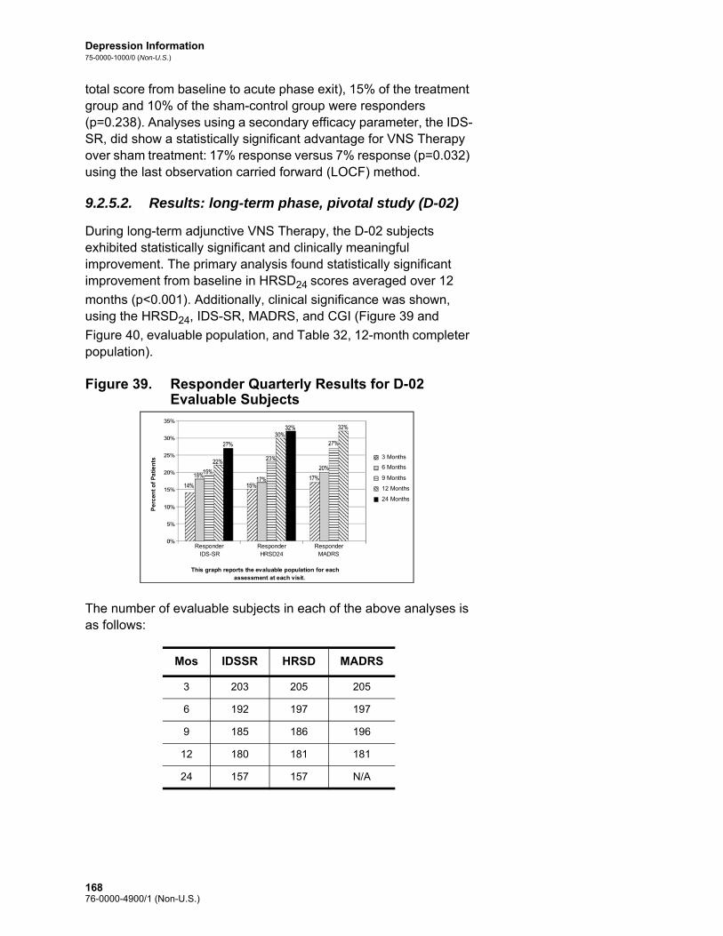
Depression Information75-0000-1000/0 (Non-U.S.)
total score from baseline to acute phase exit), 15% of the treatment group and 10% of the sham-control group were responders (p=0.238). Analyses using a secondary efficacy parameter, the IDS-SR, did show a statistically significant advantage for VNS Therapy over sham treatment: 17% response versus 7% response (p=0.032) using the last observation carried forward (LOCF) method.
9.2.5.2. Results: long-term phase, pivotal study (D-02)
During long-term adjunctive VNS Therapy, the D-02 subjects exhibited statistically significant and clinically meaningful improvement. The primary analysis found statistically significant improvement from baseline in HRSD24 scores averaged over 12
months (p<0.001). Additionally, clinical significance was shown, using the HRSD24, IDS-SR, MADRS, and CGI (Figure 39 and
Figure 40, evaluable population, and Table 32, 12-month completer population).
Figure 39. Responder Quarterly Results for D-02 Evaluable Subjects
The number of evaluable subjects in each of the above analyses is as follows:
Mos IDSSR HRSD MADRS
3 203 205 205
6 192 197 197
9 185 186 196
12 180 181 181
24 157 157 N/A
Responder IDS-SR Responder
HRSD24 Responder MADRS
This graph reports the evaluable population for each assessment at each visit.
Pe
rcen
t o
f P
ati
en
ts 3 Months
6 Months 9 Months 12 Months 24 Months
16876-0000-4900/1 (Non-U.S.)

Depression Information75-0000-1000/0 (Non-U.S.)
Figure 40. Remitter Quarterly Results for D-02 Evaluable Subjects
The number of evaluable subjects in each of the above analyses is as follows:
Mos IDSSR HRSD MADRS
3 203 205 205
6 192 197 197
9 185 186 196
12 180 181 181
24 157 157 N/A
Responder IDS-SR Responder
HRSD24 Responder MADRS
This graph reports the evaluable population for each assessment at each visit.
Per
cen
t o
f P
ati
en
ts 3 Months
6 Months 9 Months 12 Months 24 Months
16976-0000-4900/1 (Non-U.S.)

Depression Information75-0000-1000/0 (Non-U.S.)
Table 32. Responders, Remitters, and Percent Change Pivotal (D-02) Study, 12-Month Completer Population
9.2.5.3. Quality of life assessment
The observed improvement in depression among subjects in the pivotal (D-02) study long-term phase was supported by improved quality of life as measured by the MOS SF-36. Significant improvement was observed in several of the MOS SF-36 subscales: Vitality, Social Functioning, Role Functioning – Emotional, Mental Health (p<0.01).
HRSD24a IDS-SRb MADRSc
12-Month Visit
12-Month Visit
12-Month Visit
Responders – N (%)
Treatment 34/103 (33%)2 25/102 (25%) 34/103 (33%)2
Delayed treatment 18/71 (25%) 13/71 (18%) 22/71 (31%)1
All 12-Month Completers 52/174a
(30%)338/173 (22%)1 56/174 (32%)3
Remitters – N (%)
Treatment 19/103 (18%)2 16/102 (16%)1 25/103 (24%)2
Delayed treatment 10/71 (14%) 10/71 (14%) 16/71 (23%)1
All 12-Month Completers 29/174 (17%)2 26/173 (15%)2 41/174 (24%)3
Mean Percent Change from Baseline
Treatment 31.9% 3 27.8% 3 32.9% 3
Delayed treatment 26.5% 3 17.3% 3 26.3% 3
All 12-Month Completers 29.7% 3 23.5% 3 30.2% 3
1 p<0.05; 2 p<0.01; 3 p<0.001; Response and Remitter used the Exact McNemar’s test compared with 3 months; Percent Change used the paired t-test (change from pre-stimulation baseline).
a Three subjects did not have 12-month HRSD24 assessments. (These 3 subjects
did have 11-month assessments.)b One subject did not have a baseline IDS-SR assessment and several others did
not have 12-month assessments, which accounts for the varying Ns in the comparison of HRSD24 with IDS-SR data.
c Two delayed-treatment subjects did not have 12-month MADRS assessments.
17076-0000-4900/1 (Non-U.S.)

Depression Information75-0000-1000/0 (Non-U.S.)
9.2.6. Results: Comparison of D-02 and D-04 Studies
The D-04 study provided a control group of similarly ill subjects who received usual standard-of-care therapies for 12 months but were not implanted with the VNS Therapy device. See Table 31.
9.2.6.1. Primary effectiveness outcome
The primary and secondary analyses comparing subjects treated with VNS Therapy plus usual standard-of-care (pivotal, D-02) with subjects treated with usual standard-of-care alone (comparative, D-04) showed that adjunctive VNS Therapy produced statistically significantly greater improvement in depressive symptoms over 1 year of treatment. The primary efficacy analysis, a repeated measures linear regression analysis of the IDS-SR over 1 year, showed a statistically significant (p<0.001 evaluable; p<0.001 intent to treat) difference favoring adjunctive VNS Therapy (see Figure 41).
Figure 41. Comparison of IDS-SR Scores of Pivotal (D-02) Versus Comparative (D-04) Study Subjects by Quarter (Repeated Measures Linear Regression Analysis), Evaluable Population
B/L 3 mos 6 mos 9 mos 12 mos
Mean D-04 Scores
43.0 (N=124)
38.1 (N=120)
37.5 (N=119)
37.3 (N=116)
38.5 (N=112)
Mean D-02 Scores
43.0 (N=201)
36.9 (N=200)
35.1 (N=195)
33.7 (N=183)
33.7 (N=177)
Predicted Mean Difference
0 -1.2 -2.4 -3.6 -4.8
Actual Mean Difference
-0.9 -4.6 -4.1 -5.0 -6.6
30
35
40
45
Baseline 3 Month 6 Month 9 Month 12 Month
D - 04 D - 02
Pre
dic
ted
M
ean
IDS
- SR
Sco
res
17176-0000-4900/1 (Non-U.S.)

Depression Information75-0000-1000/0 (Non-U.S.)
9.2.6.2. Secondary analyses
Additionally, the following secondary analyses were statistically significant and showed adjunctive VNS Therapy improved depressive symptoms more than usual standard-of-care alone after 12 months of therapy. See Figure 42 and Figure 43.
Figure 42. Secondary Analyses: Categorical Outcomes at 12 Months (Evaluable Observed Analysis)
Figure 43. Secondary Analyses: CGI-I Categorical Outcome at 12 Months (Evaluable Observed Analysis)
9.2.7. Clinical Benefit Over Time
To explore whether these subjects were receiving benefit that was not fully reflected in the response rates, they were assigned to categories according to “clinical benefit.” Clinical benefit was prospectively defined as extraordinary (≥75% improvement in
22%
15%
30%
17%
12%
4%
13%
7%
0
10
20
30
40
% o
f P
atie
nts
Responders Complete Responders
HRSD24IDS-SR30
Responders Complete Responders
D-02 (n=180)
D-04 (n=112)
D-02 (n=180)
D-04 (n=104)
p=0.029
p=0.006
p=0.003
p=0.03122%
15%
30%
17%
12%
4%
13%
7%
0
10
20
30
40
% o
f P
atie
nts
Responders Complete Responders
HRSD24IDS-SR30
Responders Complete Responders
D-02 (n=180)
D-04 (n=112)
D-02 (n=180)
D-04 (n=104)
p=0.029
p=0.006
p=0.003
p=0.031
0
5
10
15
20
25
30
35
40
% o
f P
atie
nts
37%
12%
D-02 (n=181)
D-04 (n=101)
p<0.001
Responders0
5
10
15
20
25
30
35
40
% o
f P
atie
nts
37%
12%
D-02 (n=181)
D-04 (n=101)
p<0.001
Responders
17276-0000-4900/1 (Non-U.S.)

Depression Information75-0000-1000/0 (Non-U.S.)
HRSD24), highly meaningful (50% to <75%), meaningful (25% to
<50%), minimal (0% to <25%), and worsened (less than 0%). This scale is consistent with studies in many chronic illnesses that define less than a 50% improvement as a clinically meaningful response (e.g., schizophrenia, obsessive compulsive disorder).
As shown in Figure 44, clinical benefit increased over time. The percent of subjects realizing at least a meaningful clinical benefit at 12 months was significant when compared to those experiencing a similar benefit after 3 months (Stuart-Maxwell test, p<0.001).
Figure 44. Clinical Benefit After 3, 12, and 24 Months; D-02 Evaluable Population; HRSD24
The subjects realizing at least a meaningful clinical benefit after 12 months of adjunctive VNS Therapy included subjects who sustained their 3-month meaningful or greater benefit and those who had minimal to no 3-month benefit and accrued at least a meaningful benefit after 12 months. Of the 56 subjects who had at least a meaningful benefit at 3 months, 41 (73%) continued to have at least a meaningful benefit at 12 months and 34 (61%) of these same 56 subjects had at least the same level of clinical benefit after 12 months of adjunctive VNS Therapy as they did after 3 months. Of the 118 subjects who realized minimal–to-worse clinical benefit after 3 months of adjunctive VNS Therapy, 56 (47%) had at least a meaningful benefit after 12 months of adjunctive VNS Therapy.
A majority (56%) of evaluable subjects treated with adjunctive VNS Therapy realized at least a meaningful clinical benefit after 12 months of treatment. After 24 months of VNS Therapy, 57% of evaluable subjects realized at least a meaningful clinical benefit.
9.2.8. Maintaining Response (2-Year Data)
An analysis of subjects having an initial >50% reduction in HRSD score at the designated “early” visit (3 months or 12 months) and then maintaining at least a >40% reduction at the later visit (1 or 2 years), was performed for the D-02 Study. Data are presented
70%
10%
44%
20%
11%
43%
23% 24%
10%
4%
16%
25%
0%
10%
20%
30%
40%
50%
60%
70%
80%
Minimal to Worse(<25%)
Meaningful (25% to50%)
Highly Meaningful(50% to 75%)
Extraordinary(>75%)
3 Months (N=205)
12 Months (N=180)
24 Months (N=157)
17376-0000-4900/1 (Non-U.S.)

Depression Information75-0000-1000/0 (Non-U.S.)
below in a bar graph (Figure 45), with each bar showing the percent of subjects that maintained their early response at the later observation.
Figure 45. Maintenance of Adjunctive VNS Therapy Response (% of HRSD24 Responders who Maintained Response at 1 and 2 Years)
When IDS data were used instead of HRSD data, similar results were observed (61% of 3-month responders were also responders at 12 months, 57% of 3-month responders were also responders at 24 months, and 85% of 12-month responders were also responders at 24 months). By contrast, no D-04 3-month responder maintained that response at the 12-month observation.
9.2.9. Standard-of-Care Antidepressant Treatments During the Long-term Phase of Study D-02 and During Study D-04
9.2.9.1. Electroconvulsive therapy
Electroconvulsive therapy (ECT) use was similar among the pivotal (D-02) and comparative (D-04) study subjects (7% and 6%, respectively) during the first year of observation.
9.2.9.2. Antidepressant drugs and response
Antidepressant drug use was significantly greater among pivotal (D-02) study subjects who were non-responders and comparative (D-04) study subjects overall than among the pivotal (D-02) study subjects who achieved a response (p<001). During the 12 months, 77% of the pivotal (D-02) study non-responders and 81% of all comparative (D-04) study subjects either added a new
D-020
10
20
30
40
50
60
70
80
% o
f P
atie
nts
60%
3 Mo Respondersat 1 Year
3 Mo Respondersat 2 Years
12 Mo RespondersAt 2 Years
n=30
D-02 D-02
70%69%
n=30 n=54
17476-0000-4900/1 (Non-U.S.)

Depression Information75-0000-1000/0 (Non-U.S.)
antidepressant treatment or increased an existing antidepressant dose by an antidepressant resistance rating (ARR) level of one or more. By contrast, only 56% of the pivotal (D-02) study subjects who were responders to VNS Therapy either added a new antidepressant treatment or increased an existing antidepressant dose by an antidepressant resistance rating (ARR) level of one or more.
For the evaluable group at 12-months, 61 subjects were responders while 144 subjects were non-responders (N=205). On a percentage basis twice as many pivotal (D-02) study responders had no ARR changes or removed or decreased medications by at least one ARR level or were not taking medications as compared to the non-responders (44% versus 23%, respectively).
9.2.9.3. Medication censoring analyses
Additional medication censoring analyses were performed using the D-02 and the D-02 versus D-04 repeated measures linear regression methods to evaluate further the potential effect of medication changes. This censoring approach used a missing data paradigm to calculate the D-02 results that would have been observed under conditions where no intercurrent changes in medications would have occurred in the D-02 group. The approach censors the D-02 IDS-SR scores after the point at which a subject had a significant medication increase (ARR increase) or ECT treatment, and the last pre-censored score is carried forward and used for subsequent assessment periods. The censoring had the effect of truncating the VNS treatment benefit from 12 months to an average of 7 months. In the D-02 censored analysis, the average HRSD24 change from baseline was –0.25 points per month in the
repeated measures linear regression (p<0.001).
The D-02 censored versus D-04 IDS-SR repeated measures linear regression comparison was an asymmetric comparison of the VNS group treated for 7 months with VNS plus no changes from baseline treatments versus the D-04 group treated for a full 12 months with unlimited standard-of-care treatments (no censoring was performed on the D-04 data). The results of the censoring analysis approached but did not reach statistical significance in the comparison of the D-02 group with the D-04 group (p = 0.052; 95% CI -0.37, 0.00) for the evaluable population.
9.2.10. Bibliography
A bibliography of animal, clinical, and mechanism of action studies is available from Cyberonics on request.
17576-0000-4900/1 (Non-U.S.)

Depression Information75-0000-1000/0 (Non-U.S.)
9.3. Guidelines for Patient Follow Up
During the first few weeks after implantation, the patient should be seen to confirm wound healing and proper pulse generator operation. The pulse generator’s output current for both the Magnet and the programmed stimulation must be 0.0 mA for the first 14 days after implantation.
The VNS Therapy System is an adjunctive therapy to existing (prior to device implantation) antidepressant medications. Cyberonics strongly encourages physicians to keep all antidepressant medications stable for the first three months of stimulation before attempting to reduce or change a patient’s medication.
During initial programming, the output current should be programmed to start at nominal parameters (0 mA) and then be slowly increased in 0.25 mA increments until the patient feels the stimulation at a comfortable level. Patients who are receiving replacement pulse generators should also be started at nominal parameters, with 0.25 mA-step increases to allow re-accommodation.
Note: For instructions on printing out data, see the Programming Software physician’s manual.
At each patient visit, the pulse generator should be interrogated, using the appropriate version of the VNS Therapy Programming Software. After reprogramming and/or diagnostics testing, data should be printed out and filed. These data can be used for comparison with a patient’s own records to evaluate the VNS Therapy System, to confirm proper VNS Therapy System functioning, and to assess the need for reprogramming.
The median output current used during the clinical studies was about 1.0 mA. Other standard treatment settings were 20 Hz, 500 μsec pulse width, 30 sec ON time, and five min OFF time. There are no data to verify that these are optimal parameters.
There is no proven correlation at present between high output current (mAmps) and device effectiveness, nor is there a standard treatment level that needs to be achieved during treatment ramping. VNS Therapy System treatment should not be uncomfortable, nor should it cause bothersome side effects. Patients should be observed for at least 30 minutes after the last stimulation adjustment to make certain that they are comfortable with programmed stimulation.
Although Cyberonics recommends adjusting output current as necessary, there are no controlled data at this time to indicate that higher current levels are associated with better efficacy. Patients whose depression is well controlled at follow up should not have
17676-0000-4900/1 (Non-U.S.)

Depression Information75-0000-1000/0 (Non-U.S.)
their settings changed unless they experience uncomfortable side effects.
The subsequent follow-up schedule and the nature of each examination should be determined by the physician on the basis of patient response to and tolerance of the implant. In all other respects, follow up should be performed in accordance with the standard medical practice for patients with depression.
In the event intolerable adverse events are reported, physicians should always try reducing the output current (mA) as a means of eliminating or reducing the severity of an event. Additionally, physicians should instruct patients or caregivers on the application of the Magnet to turn the pulse generator off (output current 0 mA) if an adverse event becomes intolerable.
9.4. Individualization of Treatment
Note: See the Programming Software physician’s manual.
Patients should be started on stimulation at a low current output setting (0.25 mA), and the current should be increased gradually to allow accommodation to the stimulation. For patient comfort, the output current should be increased in 0.25 mA increments until a comfortable tolerance level is reached. Physicians should appreciate that some patients will accommodate to stimulation levels over time and should therefore allow further increases (in 0.25 mA steps) in output current, if needed.
Table 33 lists the stimulation parameters reported at 12 months of VNS Therapy in the pivotal (D-02) study.
Table 33. Stimulation Parameters at 12 Months of VNS Therapy in the Pivotal (D-02) Study
The Magnet output current should be set to 0 mA.
Stimulation Parameters
Median Value at 12 Months
Range
Output current 1.0 0 to 2.25
Frequency 20 Hz 2 to 30 Hz
Pulse width 500 μsec 130 to 750 μsec
ON time 30 sec 7 to 60 sec
OFF time 5 min 0.3 to 180 min
17776-0000-4900/1 (Non-U.S.)

Depression Information75-0000-1000/0 (Non-U.S.)
9.5. Patient Counseling Information
In the event of uncomfortable adverse events, continuous stimulation, or other malfunction, the patient must be advised to hold or tape the Magnet directly over the implanted pulse generator to prevent additional stimulation. If patients or caregivers find this procedure necessary, they should immediately notify the patient’s physician.
17876-0000-4900/1 (Non-U.S.)

Epilepsy Information—Clinical Studies
VNS Therapy® System
17976-0000-4900/1 (Non-U.S.)

Epilepsy Information—Clinical Studies75-0000-2400/3 (Non-US)
10. EPILEPSY INFORMATION—CLINICAL STUDIES_______________
10.1. Clinical Studies—Safety
Note: For intended use/indications, see the Introduction to the VNS Therapy System chapter.
The VNS Therapy System was implanted in 454 patients in five clinical studies involving 611 devices (some patients had pulse generator replacements). As of August 1996, total VNS Therapy exposure in these 454 patients was 901 device-years. Individual patient exposure averaged 24 months, with a range of eight days to 7.4 years.
A total of nine patients died during these five studies. One patient died from each of the following: thrombotic thrombocytopenic purpura, drowning, aspiration pneumonia, pneumonia, and renal failure associated with drug and alcohol ingestion. No cause of death was apparent for the other four deaths, which may be classified as sudden unexpected death in epilepsy (SUDEP). None of these deaths were attributed by the investigators to the VNS Therapy System.
10.1.1. Device Performance
The VNS Therapy System performed according to its specifications. Most device issues were communication difficulties resolved by repositioning the programming wand or replacing the programming wand batteries. One high lead impedance occurred requiring replacement; a lead break due to fatigue at the electrode bifurcation was noted. Most device complaints were resolved on the day of initial complaint.
10.1.2. Adverse Events Observed in Studies
Included among the five clinical trials were two randomized, blinded, active control trials (Study E03 and E05), which involved 314 patients and the implantation of 413 devices, yielding a total VNS Therapy System exposure (inclusive of long-term follow up) of 591 device years. These trials form the basis of the rates of observed adverse events. Table 34 contains only a partial list of the more common and expected observed adverse events associated with the VNS Therapy System. A comprehensive listing of adverse events observed in studies is available by study from the Clinical Research department at Cyberonics.
Table 34 reports the adverse events from these studies during the randomized phase (approximately a 14-week observation period) and randomized phase plus long-term follow up (> 3 months)
18076-0000-4900/1 (Non-U.S.)

Epilepsy Information—Clinical Studies75-0000-2400/3 (Non-US)
through August 1996. The most common side effect associated with stimulation was hoarseness (voice alteration), which, depending on device settings, can be severe to barely perceptible. Hoarseness is reported to occur primarily during the ON period of stimulation.
Table 34. Observed Adverse Events
10.1.2.1. Status epilepticus
Valid estimates of the incidence of treatment-emergent status epilepticus among VNS Therapy System treated patients are difficult to obtain because Investigators participating in clinical trials did not all employ identical rules for identifying cases. At a minimum, two of 441 adult patients had episodes that could be described unequivocally as “status.” In addition, a number of reports were made of variably defined episodes of seizure exacerbation (for example, seizure clusters and seizure flurries).
N=413 devices in 314 patients,152 patients in the HIGH treatment group, 591 device years
Randomized + Long-term Follow Up (> 3 Months)N=314 Patients, 591 Device-Years
Randomized Phase, HIGH Only, N=152 Pts
Adverse Event (AE)
Number of
Patients*
% of
Patients†
Number of
Events
Events/Device-
Year
Number of
Patients
% of
Patients
Serious AEs‡
Surgically related 13 4.1 13 0.022 N/A N/A
Stimulation related 4 1.2 4 0.007 1 0.7
Non-serious AEs
Voice alteration 156 50 720 1.228 91 60
Increased coughing 129 41 456 0.772 57 38
Pharyngitis 84 27 182 0.308 36 24
Paresthesia 87 28 377 0.638 32 21
Dyspnea 55 18 55 0.093 32 21
Dyspepsia 36 12 98 0.166 22 15
Nausea 59 19 154 0.261 21 14
Laryngismus 10 3.2 30 0.051 9 5.9
* Number of patients reporting the event at least once.† Percentage of patients reporting the event at least once.‡ Included infection, nerve paralysis, hypesthesia, facial paresis, left vocal cord paralysis, left facial paralysis, left
hemidiaphragm paralysis, left recurrent laryngeal nerve injury, urinary retention, and low-grade fever.
18176-0000-4900/1 (Non-U.S.)

Epilepsy Information—Clinical Studies75-0000-2400/3 (Non-US)
10.1.2.2. Rebound after stimulation was stopped
Seizure frequency was monitored for one to four weeks after stimulation was stopped because of battery depletion in 72 instances (68 patients) in Study E03. Of these instances, 11 of the 72 (15%) had a greater than 25 percent increase above baseline, and 42 of the 72 (58%) had a greater than 25 percent decrease in seizure rate. The seizure rate increased by more than 1.5 standard deviations above baseline in 10 percent of instances (compared with the 7 percent expected).
10.1.3. Potential Adverse Events
Adverse events reported during clinical studies as statistically
significant are listed below in alphabetical order:1
Ataxia (Loss of the ability to coordinate muscular movement)
Dyspepsia (indigestion)
Dyspnea (difficulty breathing, shortness of breath)
Hypesthesia (impaired sense of touch)
Increased coughing
Infection
Insomnia (inability to sleep)
Laryngismus (throat, larynx spasms)
Muscle movement or twitching generally associated with stimulation
Nausea
Pain
Paresthesia (prickling of the skin)
Pharyngitis (inflammation of the pharynx, throat)
Voice alteration (hoarseness)
Vomiting
1 The lay terms provided correspond to those in the Patient’s Manual.
18276-0000-4900/1 (Non-U.S.)

Epilepsy Information—Clinical Studies75-0000-2400/3 (Non-US)
Caution: Patients who manipulate the pulse generator and lead through the skin may damage or disconnect the lead from the pulse generator and/or possibly cause damage to the vagus nerve.
Other potential adverse events possibly associated with surgery or stimulation include, but are not limited to, the following: Aspiration (fluid in the lungs)
Blood clotting
Choking sensation
Damage to nerves or vasculature in the surgical area, including the carotid artery and jugular vein
Device (pulse generator and/or lead) migration or extrusion
Dizziness
Dysphagia (difficulty swallowing)
Duodenal ulcer, gastric ulcer
Ear pain
Facial flushing
Facial paralysis, paresis
Foreign body reaction to implants, including possible tumor formation
Formation of fibrous tissue, pockets of fluid
Heart rate and rhythm changes
Hiccuping
Incision site pain
Irritability
Laryngeal irritation (sore, painful throat)
Left hemidiaphragm paralysis
Left recurrent laryngeal nerve injury
Left vocal cord paralysis
Low-grade fever
Muscle pain
Neck pain
Nerve injury
Painful or irregular stimulation
Seroma
Skin, tissue reaction
Stomach discomfort
Tinnitus (ringing in the ears)
Tooth pain
18376-0000-4900/1 (Non-U.S.)

Epilepsy Information—Clinical Studies75-0000-2400/3 (Non-US)
Unusual scarring at the incision site
Urinary retention
Vagus nerve paralysis
Weight change
Worsening of asthma and bronchitis
10.2. Clinical Studies—Effectiveness
Five acute-phase clinical studies involving the VNS Therapy System have been conducted (see Table 35). These studies enrolled 537 patients, of whom 454 were implanted with the VNS Therapy System. A total of 611 devices were implanted, and patient exposure totaled 901 device-years, with an individual mean patient exposure of 24 months (ranging from eight days to 7.4 years). A total of 45 centers participated in these studies: 40 in the United States, 2 in Germany, and 1 each in Canada, Holland, and Sweden.
Table 35. Description of Clinical Studies
All patients enrolled in all clinical studies, N=537
Description of Clinical Studies
Longitudinal Parallel
Study E01 E02 E04 E03 E05 Total
Type of study pilot longitudinal
pilotlongitudinal
openlongitudinal
randomized parallelhigh/low
randomized parallel, high/low
-
Number of patients enrolled
11 5 133 126 262 537
Number of centers* 3 2 24 17 20 45
Reference period (baseline)
weeks2 to 4
weeks3 to 6
weeks-4 to 0
weeks-12 to 0
weeks-12 to 0
-
Seizure type partial partial all types partial partial -
Number of AEDs 1 to 2 1 to 2 not specified
0 to 3 1 to 3 -
* Total includes non-U.S. centers (Canada, Holland, Germany-2, and Sweden); several U.S. centers participated in more than one study.
18476-0000-4900/1 (Non-U.S.)

Epilepsy Information—Clinical Studies75-0000-2400/3 (Non-US)
10.2.1. Purpose
The purpose of the studies was to determine whether adjunctive use of optimal stimulation of the left vagus nerve could reduce seizure frequency in patients with refractory seizures.
10.2.2. Methods
In the two randomized, blinded, active control trials (E03 and E05), patients were randomly assigned to either of two treatment groups: HIGH (believed to be therapeutic) or LOW (believed to be less therapeutic). Patients enrolled in the study were seen every four weeks during the baseline period (weeks -12 to 0). Patients meeting eligibility were implanted with the pulse generator and lead (see Table 36).
Two weeks after implantation, patients were randomized to the HIGH or LOW stimulation group, and the pulse generator was activated. Patients in the HIGH groups received a higher frequency, greater pulse width, and higher duty cycle of stimulation. The randomized treatment period that followed activation of the pulse generator lasted 14 weeks (the last 12 weeks of which were used in the efficacy analysis—the first two weeks for a treatment ramp-up period).
Table 36. Description of Patients
All patients implanted in all clinical studies, N=454
Description of Patients
Longitudinal Parallel
Study E01 E02 E04 E03 E05 Total
Number of patients implanted 11 5 124 115 199 454
Number of patients stimulated 10 5 123 115 198 451
Age in years (range) 32(20–58)
33(18–42)
24(3–63)
33(13–57)
33(13–60)
32(3–63)
Number of females (%) 4(36%)
2(40%)
57(46%)
43(37%)
104(52%)
210(46%)
Years with epilepsy (range) 22(13-32)
20(5-36)
17(0.8-48)
21(4-47)
23(2-52)
21(0.8-52)
Average number of AEDs 1.0 1.0 2.2 2.1 2.1 2.1
Median number of seizures per day at baseline
0.6 0.42 0.65 0.70 high/0.85 low
0.58 high/ 0.51 low
-
18576-0000-4900/1 (Non-U.S.)

Epilepsy Information—Clinical Studies75-0000-2400/3 (Non-US)
10.2.3. Results
The primary efficacy endpoint (percent reduction in seizure rate) was measured over 12 weeks (see Table 37). Adverse events were assessed at each patient visit.
Table 37. Principal Efficacy and Safety Results
All patients in efficacy analyses in all clinical studies, N=441
Principal Efficacy Results
Longitudinal Parallel
Study E01 E02 E04 E03 E05 Total
Number of patients in efficacy analysis
10 5 116 114 196 441
Median reduction in seizures/day
32%* 48% 22%* 23% high*/6% low
23% high†/21% low†
-
Mean reduction in seizures/day
24%‡ 40% 7%‡ 24% high‡/6% low
28% high†/15% low†
-
Difference in mean (high/low)
- - - 17%§ (3%/31%)
13%|| (2%/23%)
-
% with > 50% response 30% 50% 29% 30% high/14% low
23% high/16% low
-
Principal Safety Results Through Long-term Follow Up
Exposure (pt-yr) 45 20 245 456 135 901
SAEs¶ 9%/ - 0%/ - 6%/ - 5%/0% 7%/9% -
Discontinued (LOE/AE)# 0/1 0/0 2/3 0/2 1/3 3/9
Number of explants** 2 2 15 9 5 33
Deaths SUDEP/total†† 0/0 0/0 3/4 0/3 1/2 4/9
Within group broad analyses:* P ≤0.05, by Wilcoxon sign rank.† P <0.0001, by anova.‡ P ≤0.05, by Student’s t-test.Between group broad analyses:§ P ≤0.02, by Wilcoxon rank sum; P ≤0.02, by Student’s t-test.|| P <0.04, by aligned ranks test; P <0.02, by Student’s t-test; P <0.03, by anova.Safety information:¶ SAEs = serious adverse events.# Discontinuing for lack of efficacy (LOE)/adverse events (AE) at one year, excluding deaths.** Number of explants through August 1996, excluding deaths.†† All deaths occurred by the long-term follow-up closing date of August 1996.
18676-0000-4900/1 (Non-U.S.)

Epilepsy Information—Clinical Studies75-0000-2400/3 (Non-US)
Figure 46 and Table 38, which follow, show the results from Study E05, the largest and most recent of the randomized, blinded, active control studies:
Figure 46. Change in Seizure Frequency, Patient Distribution
(With Corresponding Table)All E05 patients completing effectiveness evaluation, N=196
Table 38. Principal Effectiveness Statistics (E05)
Patient response to VNS Therapy was examined using statistical modeling (examining group characteristics) and an evaluation of individual patients. No useful predictors were found of an increase or a decrease in seizure frequency.
All patients in E05 effectiveness analyses, N=196
Percentage Change (Seizures/Day) from Baseline
Statistics High (94) Low (102) Difference
Median -23% -21% N/A
25%, 75% Quartiles
-8.9%, -49% 4.0%, -43% N/A
95% Confidence intervals
-35%, -21% -23%, -7.7% -23%, -2.3%
Range (min, max)Mean ± SD
-100%, 52% - 89%, 171% -23%, -2.3%
-28% ± 34% -15% ± 39% -13%* ± 37%
* Difference is statistically significant (P <0.05) by analysis of variance (P=0.032) and by Cochran-Mantel-Haenszel aligned ranks (P=0.040).
0%
25%
50%
75%
100%
-100% -50% 0% 50% 100% 150% 200% Percentage Change (Seizures/Day) from Baseline
P
erce
nta
ge
of
Pat
ien
ts
LOW HIGH
18776-0000-4900/1 (Non-U.S.)

Epilepsy Information—Clinical Studies75-0000-2400/3 (Non-US)
10.2.4. Conclusions
Patients with refractory partial onset seizures treated with HIGH VNS Therapy had a statistically significant decrease in frequency of seizures, compared with the baseline and compared with patients treated with LOW (active control) VNS Therapy. As indicated in Figure 46, most patients had a reduction in seizure frequency; some, however, had either no change or an increase in seizure frequency. The most common treatment-related adverse events were voice alteration and dyspnea. Treatment was well tolerated, with 97 percent (306 of 314) of the implanted patients continuing into the long-term follow-up phase of the study.
10.2.5. Long-term Data from Uncontrolled Follow Up
Long-term data (> 3 months’ stimulation) were collected on all available E01 through E04 study patients (see Table 39). At the time the VNS Therapy System Premarket Approval Application was considered by the U. S. Food and Drug Administration, long-term data on most Study E05 patients were not available. These long-term follow-up data are uncontrolled because they come from an open-label protocol in which both the antiepileptic drug medications and the VNS Therapy device settings were allowed to be changed.
Ninety-five percent (95%) of patients were continuing one year after their original implant; 82 percent were still receiving stimulation at two years; and 69 percent were receiving stimulation at three years. Some E04 patients had not yet had the opportunity to reach two or three years of stimulation and therefore were not used in the calculations. Additionally, 28 E03 patients were implanted outside the United States in countries that later received commercial approval, and data were available through one year of stimulation only.
18876-0000-4900/1 (Non-U.S.)

Epilepsy Information—Clinical Studies75-0000-2400/3 (Non-US)
Table 39. Patient Summary Chart
Table 40 shows the number of patients included in the efficacy analysis. It is apparent from the table that not all continuing patients were used in the efficacy analysis. This difference was mostly because of missing data (some patients kept only sporadic records over the long term), although two patients were not used because they had lobectomy surgery, which had affected their seizure rates.
Patients continuing treatment as of 8/22/96
Study E01 E02 E03 E04 Total
No. of patients randomized/stimulated
10 5 115 123 253
No. of patients entering long-term phase
10 5 113 123 251
No. of continuing patients being treated for up to 1 year/No. started
10/10 5/5 111/115 112/121* 238/251
No. of continuing patients being treated for up to 2 years/No. started
9/10 4/5 71/87† 58‡/70 142/172
No. of continuing patients being treated for up to 3 years/No. started
7/10 3/5 57/87 21§/24 88/126
* Two E04 Study patients had not been implanted long enough to reach the one-year date after implantation.
† Twenty-eight (N=28) commercial European patients were excluded from follow up after one year of treatment because of the commercial release of the VNS Therapy System in those countries.
‡ As of 8/22/96, only 70 patients had been implanted long enough to reach the two-year treatment period; 58 of the 70 were continuing.
§ As of 8/22/96, only 24 patients had been implanted long enough to reach the three-year treatment period; 21 of the 24 were continuing.
18976-0000-4900/1 (Non-U.S.)

Epilepsy Information—Clinical Studies75-0000-2400/3 (Non-US)
Table 40. Patients Used for Efficacy Analysis
10.2.5.1. Long-term results
Available long-term data from uncontrolled, open-label protocols during which antiepileptic drug and VNS Therapy device setting changes were allowed suggest improved efficacy over the first 24 months of treatment, with stabilization of this improvement after two years (see Figure 47). As evident from Table 40, these long-term data are limited at years two and three, with no patients being represented in the three-year analysis from Studies E04 or E05. There can be no assurances that the efficacy of the VNS Therapy treatment will continue to improve or will not decline over time, nor can there be assurances that additional long-term data will not reveal new adverse information presently unknown to Cyberonics. However, currently available long-term data do not suggest an increase or a worsening of adverse events, or a decline in efficacy.
Study E01 E02 E03 E04 Total
No. of patients randomized/stimulated
10 5 115 123 253
No. of patients entering long-term phase
10 5 113 123 251
No. of patients used in 1-year efficacy analysis/No. stimulated
10/10 4/5 102/111 86/112 202/238
No. of patients used in 2-year efficacy analysis/No. stimulated
8/9 2/4 51/71* 34/58† 95/142
No. of patients used in 3-year efficacy analysis/No. stimulated
4/7 2/3 49/57 0‡ 55/67
* Of the 71 patients continuing, efficacy data were available for only 51.† Of the 58 patients, efficacy data were available for only 34.‡ No data were available at the three-year time for the E04 patients.
19076-0000-4900/1 (Non-U.S.)

Epilepsy Information—Clinical Studies75-0000-2400/3 (Non-US)
Figure 47. Median Percentage Change in Seizure Frequency
* The acute phase results include seizure frequencies of the E03 Study LOW stimulation group, which included one-half the E03 patients, N=57. Patients were permitted to change their AEDs during these long-term follow-up studies, and these changes may have contributed to the change in seizure frequency.
10.2.5.2. Other information
In the United States, the VNS Therapy System is approved for use in adults and adolescents over 12 years of age with partial onset seizures that are refractory to antiepileptic medications. Unlike the two randomized studies, Study E04, an open-label safety study, included patients 12 years old and younger, and patients with generalized seizures. Sixteen patients under age 12, ranging from 3.6 to 12 years old, were evaluated. (Two additional patients had unevaluable seizure data.) These patients were found to have a 17.9 percent median decrease in seizures during the acute phase, with 31 percent of the patients experiencing a greater than 50 percent decrease.
Additionally, 25 patients with generalized seizures were evaluated. (Two additional patients had unevaluable seizure data.) These patients were found to have a 46.6 percent median decrease in seizures during the acute phase, with 44 percent experiencing a greater than 50 percent decrease. The E04 results (N=116 analyzed), including patients younger than 12 and those with generalized seizures, showed a 22 percent median decrease during the acute phase, with 29 percent of the patients experiencing a greater than 50 percent decrease.
N=55 N=95 N=202 N=244 ACUTE * 12 Mo. 24 Mo. 36 Mo.
0
-10
-20
-30
-40
-50
-17.05
-31.31
-40.74 -40.42
E01/E02/E03/E04 Patients (Pooled Results)
Pe
rce
nta
ge
Ch
an
ge
fr
om
Ba
se
lin
e
19176-0000-4900/1 (Non-U.S.)

Epilepsy Information—Clinical Studies75-0000-2400/3 (Non-US)
The E04 results (N=86 analyzed), excluding patients younger than 12 and those with generalized seizures, showed an 18.3 percent median decrease in seizures during the acute phase, with 27.9 percent of the patients experiencing a greater than 50 percent decrease.
10.2.5.3. Mechanism of action
The precise mechanism(s) by which the VNS Therapy System exerts its anticonvulsant action is unknown. In animal models designed to examine anticonvulsant activity, vagus nerve stimulation prevented seizures or seizure spread in these models: maximum electroshock (MES), pentylenetetrazol (PTZ) tests, 3-mercaptopropionic acid (3-MPA), alumina gel, potassium penicillin, strychnine, and kindling. With the exception of the alumina gel model, vagus nerve stimulation did affect the heart and respiratory rate, which may have contributed to the alteration in seizure activity.
Localization of vagus-initiated activity in the brain has been
observed through animal studies of fos1 immunoreactivity, regional brain glucose metabolism, and positron emission tomography (PET) imaging in human patients.
An [15O] H2O PET study in 10 patients demonstrated that vagus
nerve stimulation by the VNS Therapy System does increase blood flow in the rostral medulla, right thalamus, and right anterior parietal cortex, and bilaterally in the hypothalamus, anterior insula, and inferior cerebellum. Decreases in blood flow were detected bilaterally in the hippocampus, amygdala, and posterior cingulate gyrus.
10.2.5.4. Bibliography
A bibliography of animal and clinical studies is available from Cyberonics on request.
1 Fos is a nuclear protein that is expressed under conditions of high neuronal activity.
19276-0000-4900/1 (Non-U.S.)

Epilepsy Information—Patient Follow Up
VNS Therapy® System
19376-0000-4900/1 (Non-U.S.)

Epilepsy Information—Patient Follow Up75-0000-8600/0 (Non-US)
11. EPILEPSY INFORMATION—PATIENT FOLLOW UP ____________
11.1. Guidelines for Patient Follow Up
11.1.1. After Implantation
During the first few weeks after implantation of new or replacement devices, the patient should be seen to confirm wound healing and proper pulse generator operation. The pulse generator’s output current for both the magnet and the programmed stimulation must be 0 mA for the first 14 days after implantation.
The VNS Therapy System is an adjunctive therapy to existing (prior to device implantation) antiepileptic medications. Cyberonics strongly encourages physicians to keep all antiepileptic medications stable for the first three months of stimulation before attempting to reduce or change a patient’s medication.
11.1.2. Follow-up Visits
11.1.2.1. Initial Titration Visits (Ramping Up VNS Therapy)
Note: (Model 106 only) A smaller output current step size of 0.125 mA is available (up to 2 mA) to allow for patient tolerability to device stimulation.
During initial programming, the patient may be seen more frequently to make adjustments in therapy until a target level (i.e., adequate seizure control with minimal side effects) is reached. Once stimulation is ready to be programmed ON, the output current should be slowly increased in 0.25 mA increments until the patient feels the stimulation at a comfortable level. Patients who are receiving replacement pulse generators should also be titrated in the same manner to allow re-accommodation. See “Dosing Strategies” for more information.
11.1.2.2. Long-term Follow Up
The subsequent follow-up schedule and the nature of each examination should be determined by the physician on the basis of patient response to and tolerance of the implant. In all other respects, follow up should be performed in accordance with the standard medical practice for patients with epilepsy.
In the event intolerable adverse events are reported, physicians should always try reducing stimulation parameters as a means of eliminating or reducing the severity of an event. See “Tolerability Strategies” for parameter adjustment recommendations. Additionally, physicians should instruct patients or caregivers on the
19476-0000-4900/1 (Non-U.S.)

Epilepsy Information—Patient Follow Up75-0000-8600/0 (Non-US)
application of the magnet to turn the pulse generator off (output current 0 mA) if an adverse event becomes intolerable.
11.1.2.3. Typical Follow-up Visit Activities
Note: For instructions on printing out data, see the Programming Software Physician’s Manual.
At each patient visit, the pulse generator should be interrogated, using the appropriate version of the VNS Therapy programming software. Stimulation adjustments may also be performed depending on patient response and/or tolerability.
VNS Therapy System treatment should not be uncomfortable, nor should it cause bothersome side effects. Patients should be observed for at least 30 minutes after the last stimulation adjustment to make certain that they are comfortable with all available programmed stimulation modes.
Diagnostic testing should also be performed at each visit to confirm proper functioning of the VNS Therapy System. Additionally, Cyberonics recommends that testing of the magnet output be performed while the patient is still in the physician’s office to ensure tolerability of the Magnet Mode output.
For generators with AutoStim Mode, heartbeat detection performance should be evaluated at each visit.
After reprogramming and/or diagnostics testing, data should be printed out and filed. These data can be used for comparison with a patient’s diary or own records to evaluate the VNS Therapy System, to confirm proper VNS Therapy System functioning, and to assess the need for reprogramming. At the end of the session, a final interrogation should be performed to confirm parameters are set to the intended dose before the patient leaves the office.
19576-0000-4900/1 (Non-U.S.)

Epilepsy Information—Patient Follow Up75-0000-8600/0 (Non-US)
11.2. Individualization of Treatment
11.2.1. Therapy Parameters Used in Clinical Trials
Caution: (Model 106 only) It is recommended that the output current for the AutoStim Mode not exceed the greater of output current for the Normal Mode or Magnet Mode, especially for patients who experience discomfort or adverse stimulation effects (e.g., during sleep).
Caution: (Model 106 Serial Numbers < 80000 only) Magnet Mode output current should be set at least 0.125 mA higher than AutoStim output current, to prevent rare instances where a device safety feature disables stimulation due to repeated magnet applications.
The average output current used during the clinical studies after 3
months of stimulation was about 1 mA.1 Other standard Normal Mode treatment settings were 30 Hz, 500 µsec pulse width, 30 seconds ON time, and 5 minutes OFF time. There are no data to verify that these are optimal parameters.
Table 41 lists the range of stimulation parameters after 3 months of active treatment used in the randomized, blinded, active control trials.
Table 41. High Stimulation Group Parameters
There is no proven correlation at present between high output current (mAmps) and device effectiveness, nor is there a standard treatment level that needs to be achieved during treatment ramping. However, computational modeling of vagus nerve
stimulation suggests an approximate target for nerve activation.2
11.2.2. Dosing Strategies
In general, VNS Therapy should be set to a comfortable level for the patient and increased as tolerated to help achieve efficacy. Although Cyberonics recommends adjusting output current as necessary, there are no controlled data at this time to indicate that higher current levels are associated with better efficacy. Patients whose seizures are well controlled at follow up should not have their settings changed unless they experience uncomfortable side effects.
1 Heck C, Helmers SL, DeGiorgio CM. “Vagus nerve stimulation therapy, epilepsy, and device parameters: Scientific basis and recommendations for use”. Neurology 2002; 59 (6, Suppl 4):S31-7.
Stimulation Parameters Normal Mode Magnet Mode
Output current 0–3.5 mA 0–3.5 mA
Frequency 30 Hz 30 Hz
Pulse width 500 µsec 500 µsec
ON time 30 sec 30 sec
OFF time 5 min N/A
2 Helmers SL, Begnaud J, Cowley A, et al. “Application of a computational model of vagus nerve stimulation”. Acta Neurol Scand. 2012; 126 (5):336-43.
19676-0000-4900/1 (Non-U.S.)
Epilepsy Information—Patient Follow Up75-0000-8600/0 (Non-US)
Note: See the Programming Software Physician’s Manual.
Patients should be started on stimulation at a low current setting (0.25 mA), and the current should be increased gradually to allow accommodation to the stimulation. For patient comfort, the output current should be increased in 0.25 mA increments until a comfortable tolerance level is reached. Physicians should appreciate that some patients will accommodate to stimulation levels over time and should therefore allow further increases (in 0.25 mA steps) in output current, if needed.
The magnet output should be programmed at each visit, if necessary, to a level that is perceptible to the patient. This is typically set 0.25 mA higher than the Normal Mode output current. Some patients have reported that it is easier to verify daily that stimulation is being delivered if the magnet output current is set to one step above normal stimulation settings. This slightly higher output current is intended to allow patients who have accommodated to normal stimulation to recognize or perceive the magnet stimulation, thereby confirming device function.
Caution: (Model 106 Serial Numbers < 80000 only) Magnet Mode output current should be set at least 0.125 mA higher than AutoStim output current, to prevent rare instances where a device safety feature disables stimulation due to repeated magnet applications.
For generator models with AutoStim, the AutoStim output current should be set no greater than the Magnet Mode output current. You may choose to set AutoStim output current between the Normal and Magnet Mode output currents, or equal to Normal Mode for comfort or tolerability.
Table 42 lists the suggested initial stimulation parameters to begin titration of VNS Therapy
19776-0000-4900/1 (Non-U.S.)

Epilepsy Information—Patient Follow Up75-0000-8600/0 (Non-US)
Table 42. Suggested Initial Stimulation Parameters (≥ 2 Weeks After Implant)
11.2.3. Tolerability Strategies
After each output current increase, evaluate the patient for tolerability. If an increase in output current is not tolerable, other stimulation parameters may be adjusted as shown in Table 43 to help with patient tolerability.
Prior to each parameter adjustment, it is recommended to revert the output current to the last level that was tolerated by the patient.
Make the parameter adjustment and try the increase in output current again.
If the patient was already started at the lower recommended settings for pulse width and frequency, reductions in output current and further reductions in pulse width may be the only course of action. However, if the pulse width is reduced to 130 µsec, the output current should be increased to minimize the impact to the overall amount of therapy delivered. Literature has shown that a
NO
RM
AL
Output Current 0.25 mA
Signal Frequency† 20 - 30 Hz
Pulse Width† 250 - 500 µsec
Duty Cycle: 10%
Signal ON Time 30 sec
Signal OFF Time 5 min
AU
TO
ST
IM* Output Current 0.25 - 0.375 mA
ON Time 60 sec
Pulse Width 250 - 500 µsec
MA
GN
ET Current 0.5 mA
ON Time 60 sec
Pulse Width 250 - 500 µsec
* Not available in all generator models.
† Some patients may find 20 Hz/250 µsec more tolerable. For this reason, some physicians prefer to start at the lower settings, and increase as tolerable. Other physicians may prefer to start at the higher settings, and adjust downward if needed for tolerability (Heck, Helmers, and DeGiorgio. 2002).
19876-0000-4900/1 (Non-U.S.)

Epilepsy Information—Patient Follow Up75-0000-8600/0 (Non-US)
higher output current is needed to activate the vagus nerve when
pulse widths below 250 µsec are used.1 , 2
Table 43. Parameter Adjustments for Tolerability3
Table 44 provides an example of how to titrate when adjusting for patient comfort. Each example includes what the starting signal frequency and/or pulse width might be.
Table 44. Example — Tolerability Adjustments During Titration
If the output currents are reduced to address side effects, but the target level (i.e., adequate seizure control with minimal side effects)
1 Koo B, Ham SD, Sood S, Tarver B. “Human vagus nerve electrophysiology: A guide to vagus nerve stimulation parameters”. J Clin Neurophysiol 2001;18 (5):429-33.
2 Helmers SL, Begnaud J, Cowley A, et al. “Application of a computational model of vagus nerve stimulation”. Acta Neurol Scand. 2012; 126 (5):336-43.
Parameter Adjustment
Pulse Width 500 250 µsec
Signal Frequency 30 20 Hz*
Output Current 0.125 mA† or
0.25 mA
* 25 Hz is also available
† Only available in certain generator models
3 Heck C, Helmers SL, DeGiorgio CM. “Vagus nerve stimulation therapy, epilepsy, and device parameters: Scientific basis and recommendations for use”. Neurology 2002; 59 (6, Suppl 4):S31-7.
Programming Steps
Parameter Adjustment Purpose
1 Output Current +0.25 mA Titration attempt
If patient experiences discomfort:
2 Output Current -0.25 mA Comfort adjustment
3 Pulse Width or
Signal Frequency
500 250 µsecor
30 20 Hz
If parameter reduction is tolerable, continue titration.
4 Output Current +0.25 mA Titration attempt
19976-0000-4900/1 (Non-U.S.)

Epilepsy Information—Patient Follow Up75-0000-8600/0 (Non-US)
has not been reached, future attempts at increasing output current are recommended.
11.2.4. Example Dosing Approach
This section describes a 2-phase dosing approach.1 The goal of Phase 1 (0.5-3 months after implant) is to increase the output current to a target range. The goal of Phase 2 (3-18 months after implant) is to increase the duty cycle. If the patient achieves desired outcomes at any point, further adjustments may be stopped.
11.2.4.1. Phase 1 - Output Current
Two weeks following implantation surgery, apply the initial recommended settings as described in Table 42. You may choose to start the pulse width and frequency at 500 µsec and 30 Hz respectively, and adjust down as needed for tolerability. Or, you may start at the lower range of the recommended settings, 250 µsec and 20 Hz.
With a duty cycle of 10%, increase the output current upward in 0.25 mA steps over the next several weeks. The target for output
current is 1.5-2.25 mA depending on pulse width selection:2
1.5 mA if PW 500 µsec
1.75 mA if PW 250 µsec
2.25 mA if PW 130 µsec
Multiple step (0.25 mA) increases can be made in output current during a single visit if tolerated by the patient. Frequent visits during this titration phase may allow for faster progress toward the target output current. Table 45 shows how all three stimulation modes can be adjusted:
1 Heck C, Helmers SL, DeGiorgio CM. “Vagus nerve stimulation therapy, epilepsy, and device parameters: Scientific basis and recommendations for use”. Neurology 2002; 59 (6, Suppl 4):S31-7.
2 Helmers SL, Begnaud J, Cowley A, et al. “Application of a computational model of vagus nerve stimulation”. Acta Neurol Scand. 2012; 126 (5):336-43.
20076-0000-4900/1 (Non-U.S.)

Epilepsy Information—Patient Follow Up75-0000-8600/0 (Non-US)
Table 45. Output Current Adjustments
11.2.4.2. Phase 2 (Duty Cycle)
Once the output current has reached the target, duty cycle may be adjusted upward to assess better patient response. Allow adequate time between duty cycle adjustments for patient evaluation. Adjustments to duty cycle should be less frequent (approximately 3-6 months). Table 46 shows the recommended duty cycle increases.
Table 46. Duty Cycle Table of Adjustments
Table 47 shows an example of Phase 1 and 2 adjustments over time.
Mode Step 1 Step 2Steps 3, 4, 5 ...
Target*
Normal (mA) 0.25 0.50 +0.25 1.5- 2.25
AutoStim (mA)† 0.375 0.625 +0.25 1.625 - 2.25†
Magnet (mA) 0.50 0.75 +0.25 1.75 - 2.5
* Target output current depends on pulse width selection. See combinations above.
† AutoStim Mode is not available for all generator models. Output currents for AutoStim Mode may be set in between Normal and Magnet mode selections (as shown), or equal to the Normal Mode for comfort or tolerability.
OFF Time (min)
0.2 0.3 0.5 0.8 1.1 1.8 3 5 10
ON
Tim
e (
sec
)
7 58 44 30 20 15 10 6 4 2
14 69 56 41 29 23 15 9 6 3
21 76 64 49 36 29 19 12 8 4
30 81 71 57 44 35 25 16 10 5
60 89 82 71 59 51 38 27 18 10
For devices with AutoStim enabled, OFF times ≤ 0.8 minutes cannot be used.
20176-0000-4900/1 (Non-U.S.)

Epilepsy Information—Patient Follow Up75-0000-8600/0 (Non-US)
Table 47. Example — Phase 1 and 2 Adjustments Over Time
11.2.5. Optimize the Model 106 Heartbeat Detection Setting
The Model 106 generator’s Seizure Detection Algorithm relies on accurate heartbeat detection in order to perform as intended. The device performs heartbeat detection by detecting the R-wave of the ECG morphology, which is known to vary based on the position of the patient. Therefore, a pre-operative assessment of R-wave amplitudes at different body positions is recommended in order to optimize the Heartbeat Detection setting. Instructions for the assessment can be found in the Implantation Procedure chapter. Of the measurements recorded, use the average R-wave amplitude to choose an appropriate Heartbeat Detection setting based on the range mapping in Table 48.
Months After Implant
0.5 -3 3-6 6-9 9-12 12-15 15-18 18+
Ph
ase
Du
ty C
ycl
e*
* Additional adjustments after 41% could include 44% and 58%. See Duty Cycle table for recommended ON-time / OFF-time combinations.
20276-0000-4900/1 (Non-U.S.)

Epilepsy Information—Patient Follow Up75-0000-8600/0 (Non-US)
Table 48. Heartbeat Detection Mapping
If previous R-wave measurements are not available, either of the following options can be performed as an alternative:
Repeat the measurements as instructed in the Implantation Procedure part of this physician’s manual to determine the average R-wave amplitude.
Note: The Verify Heartbeat Detection feature is described in the Model 250 Version 11.0 Programming Software Physician’s Manual.
Test each of the 5 Heartbeat Detection settings using the Verify Heartbeat Detection feature at each of the 2 body positions and choose the setting that accurately detects heartbeats in both positions.
11.2.6. Optimize the Model 106 Threshold for AutoStim Setting
Note: When Seizure Detection is ON, it is recommended that the OFF time be set to at least 1.1 minutes in order to allow the device sufficient time to detect heart rate changes during every OFF cycle.
The Model 106 is designed to allow the clinician to adjust the sensitivity of the detection algorithm. Six Threshold for AutoStim settings are available, 20% - 70% (in 10% increments), each of which correspond to the threshold that the heart rate must surpass in order to elicit a detection (only if Seizure Detection is enabled) or a detection followed by the triggering of AutoStim (if Seizure Detection and AutoStim are both enabled).
The objective to optimizing the Threshold for AutoStim setting for an individual patient is to reduce the number of detections due to normal, autonomic heart rate changes while maintaining a sensitivity that will detect heart rate changes associated with many seizures.
Clinicians may use a variety of tools to establish a reasonable baseline (e.g., heart rate monitors, Holter monitors, etc.). To assess normal baseline heart rates, the clinician can measure heart rate while the patient is lying down, sitting, or standing (HRBL). After a
baseline is established, the clinician can assess a rise in heart rate
Heartbeat Detection
Average Amplitude (mV) (across different postures)
Minimum Maximum
5 0.40 0.50
4 0.51 0.70
3 0.71 0.85
2 0.86 1.25
1 1.26 --
20376-0000-4900/1 (Non-U.S.)

Epilepsy Information—Patient Follow Up75-0000-8600/0 (Non-US)
(HRACT) during activity by monitoring the heart rate during normal
day-to-day activities. The following equation calculates the percent rise from baseline to active (%HRNORM INCR).
(HRACT - HRBL) / HRBL x 100 = %HRNORM INCR
To determine the heart rate rise during a seizure, the clinician may utilize the electrocardiogram (ECG) collected during the patient's epilepsy monitoring unit (EMU) stay.
Note: See Figure 48 for an illustration of steps 1 and 2.
1. In the electroencephalography (EEG) recording, go to the beginning of a seizure. Scan up to 5 minutes before the electrographic or clinical onset of the seizure and pick a 10-second period of time to establish a baseline heart rate (HREEG BL). Within that 10-second window, count the number of R-R intervals and multiply by 6.
HREEG BL = (# of R-R intervals) x 6
2. In the same recording, identify the beginning of the electrographic or clinical onset of the seizure. Scan the seizure and choose a 10-second period of time of maximum heart rate during the seizure (HRSZ). Count the number of R-R intervals and multiply by 6.
HRSZ = (# of R-R intervals) x 6
20476-0000-4900/1 (Non-U.S.)

Epilepsy Information—Patient Follow Up75-0000-8600/0 (Non-US)
Figure 48. Calculation of Baseline Heart Rate and Heart Rate During a Seizure
For this example (Figure 48), the baseline heart rate was assessed by scanning the ECG and finding a 10-second window of time approximately 3 minutes prior to seizure onset. Heart rate during the seizure was assessed by finding a 10-second window starting approximately 10 seconds after seizure onset.
3. Calculate the percent increase (%HRSZ INCR) from baseline:
(HRSZ - HREEG BL) / HREEG BL x 100 = %HRSZ INCR
If %HRSZ INCR > %HRNORM INCR then choose a Threshold for
AutoStim setting that represents a threshold between the two values. For example, if %HRSZ INCR is 51% and %HRNORM INCR is
34%, then a Threshold for AutoStim of 40% or 50% should be chosen. A Threshold for AutoStim setting of 50% should be chosen if a lower potential false positive rate is desired or a Threshold for AutoStim setting of 40% should be chosen if a higher sensitivity is desired.
If a patient's normal day-to-day heart rate increases are similar to or greater than their increases in heart rate during a seizure, then choose a Threshold for AutoStim setting that represents a threshold
20576-0000-4900/1 (Non-U.S.)

Epilepsy Information—Patient Follow Up75-0000-8600/0 (Non-US)
lower than the %HRSZ INCR. For example, if %HRSZ INCR is 62%
and %HRNORM INCR is 68%, then a Threshold for AutoStim setting
of 60% should be chosen. In this scenario the patient may expect to receive additional stimulations. If bothersome, these stimulations can be inhibited by applying the magnet over the generator for at least 3 seconds.
11.3. Patient Counseling Information
Patients should be told to test their pulse generator’s operation daily by performing magnet stimulation and verifying that stimulation occurs. If stimulation does not occur, their physician should be contacted.
Note: See the “Stimulation” section in the device-specific Technical Information chapter.
It should be noted that the magnet stimulation timing is not synchronized with the timing clock used for determining ON time and has a tolerance of +/- 15% or +/-7 seconds. Therefore, if the Magnet Mode ON time is programmed to 7 seconds and the pulse generator is swiped at the end of the clock cycle, magnet stimulation may not be perceived by the patient. If the patient does not perceive the magnet stimulation, he or she should be instructed to swipe the pulse generator a second time.
In the unlikely event of uncomfortable adverse events, continuous stimulation, or other malfunction, the patient must be advised to hold or tape the magnet directly over the implanted pulse generator to prevent additional stimulation. If patients or caregivers find this procedure necessary, they should immediately notify the patient’s physician.
20676-0000-4900/1 (Non-U.S.)

Implantation Procedure
VNS Therapy® System
20776-0000-4900/1 (Non-U.S.)

Implantation Procedure75-0000-8200/3 (Non-US)
12. IMPLANTATION PROCEDURE ___________________________
12.1. Physician Training / Information
All VNS Therapy System programming should be by or under the supervision of a physician familiar with the use and operation of the programming software.
12.1.1. Training Materials
Physicians implanting the VNS Therapy System should be thoroughly familiar with all associated training materials, including:
Product labeling for the pulse generator, lead, and accessories, including physician and patient manuals and directions for use
“Implant Guide for the VNS Therapy System” training manual and other brochures
Video on the proper implantation technique: “Implantation of the VNS Therapy System”
Electrode practice fixture—a device used to practice placing the helices around the left vagus nerve
12.2. VNS Therapy Devices and Surgical Materials
12.2.1. New Implants
For new implants, the following devices are needed for surgery:
2 generators (1 primary and 1 back-up)
2 leads (1 primary and 1 back-up)
12.2.2. Replacement Implants
For replacement implants, the following devices are needed for surgery:
1 replacement generator and/or lead
At least 1 back-up generator and/or lead
20876-0000-4900/1 (Non-U.S.)

Implantation Procedure75-0000-8200/3 (Non-US)
12.2.3. Other LivaNova Products
Note: Remember to use proper technique for introducing non-sterile items into a sterile field.
1 tunneler
1 accessory pack (resistors, hex screwdriver, tie downs)
1 programming system (non-sterile)
12.2.4. Surgical Materials
Note: These items are not provided by LivaNova.
The following is a list of additional materials typically used during the VNS Therapy implantation procedure:
Sterile Laser Arm Bag or equivalent (required)
Vessel loops and/or silicone sheet for manipulation of the vagus nerve (suggested but optional)
Note: See “(Model 106 generator only) Determine acceptable device implant locations” for details. This information is also summarized in the Pre-Surgical Evaluation Tool in the Model 106 package.
(Model 106 generator only) The following materials are required for performing the procedure to identify acceptable implant locations:
Commercial ECG monitor (The ECG monitor should have the capability to print out the ECG waveform/amplitudes on the lead 1 channel)
Standard, 10 mm Ag/AgCl skin electrodes
Commercial ECG Instructions For Use
Caution: The sterile lead package should only be opened after exposing the vagus nerve and selecting the LivaNova lead helical that best fits.
Caution: Do not open the package if it has been exposed to extreme temperatures or if there is any indication of external damage or damage to the package seal. Instead, return it unopened to LivaNova.
12.2.5. To Open the Sterile Package
Before the package is opened, it should be examined carefully for evidence of damage or compromised sterility. If the outer or inner package has been opened or damaged, LivaNova cannot guarantee sterility of the pulse generator or lead, and it should not be used. An opened or damaged product should be returned to LivaNova.
To open the package, do the following:1. Grasp the tab, and peel back the outer cover.
2. Observing sterile technique, lift out the sterile inner tray.
3. Grasp the inner tray’s tab, and carefully peel off the inner cover to expose the contents without dropping them.
20976-0000-4900/1 (Non-U.S.)

Implantation Procedure75-0000-8200/3 (Non-US)
12.3. Recommendations for Implantation
Caution: To maximize system performance and minimize possible mechanical damage to the nerve or lead, pay careful attention to helical placement and lead routing.
In general, implantation of the VNS Therapy System is similar to accepted practice for implantation of a cardiac pacemaker, with the exception of the placement of the helices and the subcutaneous routing of the lead body. Although the surgical approach and techniques will vary with the preference of the implanting physician, to ensure correct lead placement, this chapter of the physician’s manual provides recommendations for implantation, along with a detailed description of the order of placement of the helical electrodes and the anchor tether and other essential steps.
Note: The implant location selection procedure may be performed pre-operatively as part of the patient’s surgical work-up.
For the Model 106 generator only, the physical location of the device critically affects its ability to properly sense heart beats. Therefore care must be taken to follow the implant location selection process outlined in “(Model 106 generator only) Determine acceptable device implant locations”.
Note: For general placement of the pulse generator and lead, see Figure 52.
Critical to the long-term success of the implant are proper techniques both for the attachment of the electrodes and the anchor tether to the left vagus nerve, and for the provision of adequate strain relief below and above the sternocleidomastoid muscle.
It is recommended that the lead body be coiled and placed in the chest pocket to the side of the pulse generator.
Adequate exposure of the vagus nerve (> 3 cm) facilitates placement of the helices on the nerve. Stretching the nerve or allowing it to dry during implantation may result in temporary swelling of the nerve. Constriction of the nerve or other nerve damage may result in vocal cord dysfunction.
Note: See “Test the VNS Therapy System”.
LivaNova recommends that output of the pulse generator and performance of the implanted system be tested at the time of implantation. Although an oscilloscope can be used for measurements, LivaNova recommends use of the appropriate version of the programming software and programming wand (placed in a sterile drape) for routine system verification.
After the electrode is placed on the nerve, the electrode-nerve interface impedance is tested by connecting the lead directly to the pulse generator and performing a System Diagnostics (Lead Test). If required, a separate resistor assembly from the accessory pack can be used while performing the optional Generator Diagnostics (Pre-Implant Test).
21076-0000-4900/1 (Non-U.S.)

Implantation Procedure75-0000-8200/3 (Non-US)
12.3.1. Before Surgery and Outside of the Sterile Field
Caution: (For 103 and subsequent models only) If interrogating a pulse generator that has been exposed to low temperatures within the last 24 hours, low battery status indicator(s) may be displayed. See the Troubleshooting chapter.
12.3.1.1. Interrogate the device
To ensure proper device communication, interrogate the device while still in the sterile package. [See the Programming Software Physician’s Manual for a detailed explanation or the Programming Computer Instruction Card for a quick reference.]
12.3.1.2. Program patient data
Program the patient identification and implant date into the pulse generator. [See the Programming Software Physician’s Manual for a detailed explanation or the Programming Computer Instruction Card for a quick reference.]
12.3.1.3. (Model 106 generator only) Determine acceptable device implant locations
Note: The implant location selection process is also summarized in the Pre-Surgical Evaluation Tool in the Model 106 package.
The implant location of the Model 106 pulse generator critically affects its ability to properly sense heart beats. The following steps describe the recommended process in identifying acceptable implant locations for the Model 106 pulse generator and the lead.
12.3.1.3.1. Equipment / Materials Required
Commercial ECG monitor
The ECG monitor should have the capability to print out the ECG waveform/amplitudes on the lead 1 channel.
The ECG monitor must be configurable to a lowpass filter setting up to 150 Hz.
Standard, 10 mm Ag/AgCl skin electrodes
Commercial ECG Instructions For Use
21176-0000-4900/1 (Non-U.S.)

Implantation Procedure75-0000-8200/3 (Non-US)
12.3.1.3.2. Procedure
Note: Any commercial ECG system meeting the requirements in the section “Equipment / Materials Required” above is acceptable for use in the identification of potential implant locations procedure. Refer to the commercial ECG system Instructions For Use for proper operation or configuration.
1. Verify that the ECG monitor printing scale is set to 10mm/mV and the lowpass filter does not exceed 150 Hz.
2. Prepare the patient's skin in the left neck and chest area (e.g. remove excess body hair, perform alcohol wipe) to ensure proper contact with ECG skin electrodes.
3. Place ECG skin electrodes on the patient (a sample configuration is shown in Figure 49) as follows:
a. One electrode should be placed on the left neck, at the approximate intended implant location of the lead electrodes
b. One electrode should be placed on the chest, at the approximate intended implant location of the pulse generator
c. One electrode should be placed on the right lower abdomen or leg
d. One electrode should be placed on the left lower abdomen or leg
Note: In Figure 49, RA is the intended implant position of the lead electrode and LA is the intended implant position of the generator.
Figure 49. Sample Electrode Configuration
4. Connect the ECG leads to the electrodes:
a. The ECG lead marked RA should be connected to the electrode on the neck
b. The ECG lead marked LA should be connected to the electrode on the chest
A Collar Bone
B Sternum
C ECG Monitor
A
BC
21276-0000-4900/1 (Non-U.S.)

Implantation Procedure75-0000-8200/3 (Non-US)
c. The ECG lead marked RL should be connected to the electrode on the right lower abdomen or right leg
d. The ECG lead marked LL should be connected to the electrode on the left lower abdomen or left leg
Note: Refer to the commercial ECG Instructions For Use for proper operation or configuration.
5. Verify that the lead 1 ECG waveform is showing on the ECG monitor, wait for the ECG signal to stabilize, and collect 10 seconds of ECG data with the patient positioned lying on the left side (first of the two positions in Figure 50).
Figure 50. Patient Positions
6. Print the ECG strip and label the patient position. On the ECG strip measure the peak-to-peak R-wave amplitude in the lead 1 channel (see Figure 51) by following the scaling in Step 1. Perform this for at least 4 representative R-waves in the 10 seconds of data and record the minimum amplitude value from the assessed R-waves. This value is representative of the minimum peak-to-peak R-wave amplitude for the patient in the defined body position.
Figure 51. Sample ECG Trace with Peak-to-Peak R-wave Measurements*
*1 small division line = 0.1mV, assuming a 10 mm/mV scale
Lying, Left Side
Standing, Arms at Side
21376-0000-4900/1 (Non-U.S.)

Implantation Procedure75-0000-8200/3 (Non-US)
Note: Assuming a 10 mm/mV scale, the peak-to-peak R-wave amplitude measurements must span at least 4 lines on the ECG paper to meet the minimum requirement of 0.4 mV.
7. Verify that the minimum peak-to-peak R-wave amplitude measurement in Step 6 is 0.4 mV or greater. If this is the case, then repeat Steps 5-6 with the remaining body position defined in Figure 50 (e.g, standing with arms at side) until both body positions have been tested and the minimum peak-to-peak R-wave amplitude measurement for each body position is confirmed to be 0.4 mV or greater.
8. If the minimum peak-to-peak R-wave amplitude measurement for any one position is less than 0.4 mV, pick a new potential implant location for the generator which increases the distance between the neck electrode and the existing chest electrode, and/or is closer to the patient's heart. Place a new electrode on the new potential implant location (the old chest electrode may be removed if it is in the way), connect it to the LA lead, and repeat Steps 5-7 for both body positions until a location with adequate peak-to-peak R-wave amplitude can be identified.
9. When both body positions have been tested and the minimum peak-to-peak R-wave amplitude measurement for each body position is confirmed to be 0.4 mV or greater, the neck and chest electrode locations are acceptable selections for the Model 106 implant. Mark the spots on the neck and chest where the electrodes are and use these locations as the intended implant location during surgery. The minimum peak-to-peak R-wave amplitude measurements from the different body positions are used to configure heartbeat detection and seizure detection (See “Model 106 Heart Beat Detection and Seizure Detection Configuration”.) and post operatively to optimize the heartbeat detection setting (See “Optimize the Model 106 Heartbeat Detection Setting” in the Epilepsy Information part of this physician’s manual.).
If all practical implant locations have been exhausted without identifying a location which yields a peak-to-peak R-wave amplitude of at least 0.4 mV at both body positions, the patient may not receive additional benefit from the Automatic Stimulation feature of the AspireSR VNS Therapy System beyond the benefit of Normal Mode VNS Therapy.
21476-0000-4900/1 (Non-U.S.)

Implantation Procedure75-0000-8200/3 (Non-US)
12.3.2. Procedure Overview
Caution: This procedural overview is not a substitute for the complete implantation procedure.
Note: For Model 106 generator only, try to implant the lead and generator in the same approximate positions as determined in “(Model 106 generator only) Determine acceptable device implant locations”.
The following overview summarizes the recommended sequence for implanting the lead:1. Expose the left carotid sheath and left vagus nerve.
2. Create a pocket in the chest for the pulse generator.
3. Choose the correct size lead.
4. Tunnel the lead subcutaneously from the neck to the pulse generator pocket in the chest.
5. Attach the electrodes and anchor tether to the left vagus nerve.
6. Secure the lead parallel to the nerve.
7. Form the strain relief bend and strain relief loop.
8. Connect the lead to the pulse generator.
9. Verify that the connector pin is fully inserted, and tighten the setscrew.
10. Perform the System Diagnostics (Lead Test).
11. Place the pulse generator in the chest pocket, with the extra coiled lead to the side of the pulse generator, not behind it.
12. (106 generator only) Configure heartbeat detection.
13. (106 generator only) Configure seizure detection settings.
14. Secure the pulse generator to fascia; do not place sutures directly around or on the lead.
15. Perform the second System Diagnostics (Lead Test).
16. Interrogate the pulse generator to verify current is 0 mA.
17. Irrigate the incision site with bacitracin or other solution.
18. Close the incisions.
12.3.3. Prepare for Surgery
The surgeon should ensure that the pulse generator, lead, and tunneler are compatible.
Caution: Infections related to any implanted device are difficult to treat, and explantation of the VNS Therapy System may be required.
LivaNova recommends that the patient be given antibiotics preoperatively and that both incision sites be irrigated frequently with generous amounts of bacitracin or equivalent solution prior to closure. (These incisions should be closed with cosmetic closure techniques to minimize scarring.) Also, antibiotics should be administered postoperatively at the discretion of the physician.
21576-0000-4900/1 (Non-U.S.)
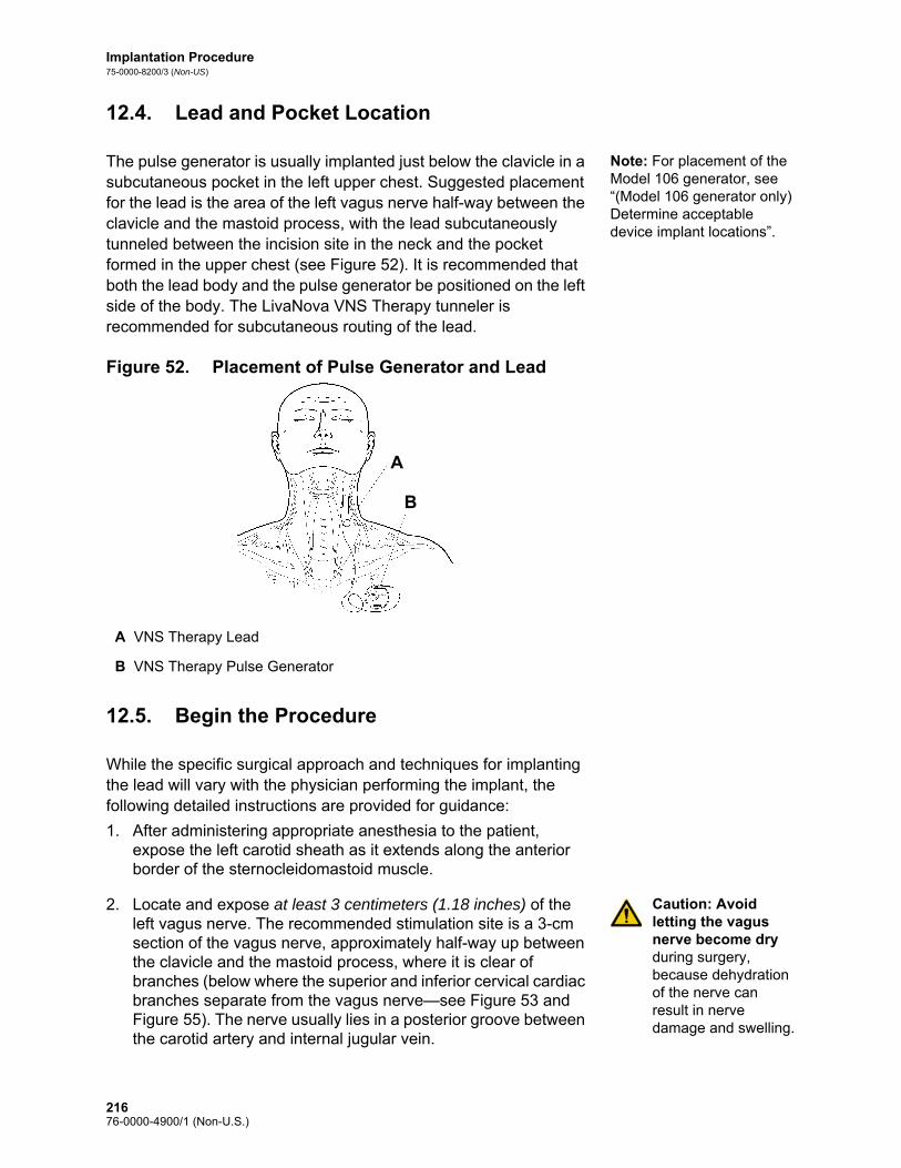
Implantation Procedure75-0000-8200/3 (Non-US)
12.4. Lead and Pocket Location
Note: For placement of the Model 106 generator, see “(Model 106 generator only) Determine acceptable device implant locations”.
The pulse generator is usually implanted just below the clavicle in a subcutaneous pocket in the left upper chest. Suggested placement for the lead is the area of the left vagus nerve half-way between the clavicle and the mastoid process, with the lead subcutaneously tunneled between the incision site in the neck and the pocket formed in the upper chest (see Figure 52). It is recommended that both the lead body and the pulse generator be positioned on the left side of the body. The LivaNova VNS Therapy tunneler is recommended for subcutaneous routing of the lead.
Figure 52. Placement of Pulse Generator and Lead
12.5. Begin the Procedure
While the specific surgical approach and techniques for implanting the lead will vary with the physician performing the implant, the following detailed instructions are provided for guidance:
1. After administering appropriate anesthesia to the patient, expose the left carotid sheath as it extends along the anterior border of the sternocleidomastoid muscle.
Caution: Avoid letting the vagus nerve become dry during surgery, because dehydration of the nerve can result in nerve damage and swelling.
2. Locate and expose at least 3 centimeters (1.18 inches) of the left vagus nerve. The recommended stimulation site is a 3-cm section of the vagus nerve, approximately half-way up between the clavicle and the mastoid process, where it is clear of branches (below where the superior and inferior cervical cardiac branches separate from the vagus nerve—see Figure 53 and Figure 55). The nerve usually lies in a posterior groove between the carotid artery and internal jugular vein.
A VNS Therapy Lead
B VNS Therapy Pulse Generator
VNS Therapy
VNS TheraA
B
21676-0000-4900/1 (Non-U.S.)

Implantation Procedure75-0000-8200/3 (Non-US)
Figure 53. Electrode Placement
Note: It is preferable to place the subcutaneous pocket along the axillary border.
3. Create a subcutaneous pocket in the chest below the clavicle for the pulse generator.
12.6. Implant the Lead
To implant the lead, follow these steps:
12.6.1. Choose a Lead
1. Choose the appropriately sized lead (2.0 or 3.0 mm electrode inner diameter) carefully. It should fit snugly without constricting the nerve. The lead (2.0 mm/.08 in) should accommodate most nerves.
Note: For lead size availability, see “Product Specifications” in the lead-specific Technical Information chapters.
Caution: The lead is available in multiple sizes. Since it is not possible to predict in patients what size lead will be needed, LivaNova recommends that at least one alternate lead size be available in the operating room. In addition, backups for leads should be available in the event of compromised sterility or damage induced during surgery.
Caution: Do not expose the lead to dust or other similar particulates, because its silicone insulation can attract particulate matter.
A Lead E Anchor Tether
B Tie-Downs F Strain Relief Bend
C Vagus Nerve G Strain Relief Loop
D Helical Electrodes H Coiled Extra Lead
A DE
F
G
H
BC
21776-0000-4900/1 (Non-U.S.)

Implantation Procedure75-0000-8200/3 (Non-US)
Caution: Do not soak the lead in saline or similar solution before implanting it, because this may cause the insulated portions of the connector pin to swell and become difficult to insert into the pulse generator.
12.6.2. Pass the Tunneler and Lead
Note: A detailed description of the tunneling tool can be found in the LivaNova Tunneler Directions for Use.
The LivaNova tunneler is used to tunnel the lead connector and lead body subcutaneously from the neck incision site to the pulse generator in the chest pocket. As an alternative, the lead connector and lead body can be tunneled subcutaneously from the neck incision site to the pulse generator in the chest pocket after placement of the electrodes and anchor tether on the nerve, and placement of strain relief with the tie-downs. (See “Place the Electrodes” and “Provide Strain Relief”, respectively.)
Caution: To maximize system performance and minimize possible mechanical damage to the nerve or lead, pay careful attention to lead routing, lead stabilization, and electrode placement.
Caution: Never route the lead through muscle.
Caution: Never suture the lead or lead body to muscle tissue.
Caution: Always use the tie-downs.
Caution: Do not place sutures directly on the lead body. Doing so may result in insulation damage or wire failure, causing premature failure of the lead.
If necessary, the tunneler can be manually shaped to help direct it through the body.
Caution: Do not manually shape the tunneler more than 25 degrees because doing so may cause the sleeve to bend or kink.
To pass the tunneler, do the following:1. Place the bullet-tip end of the tunneler through the neck incision
and tunnel subcutaneously toward the chest incision, exerting force on the handle end and directing the tunneler as necessary.
2. After the bullet tip has passed from one incision site to the other, unscrew the bullet and withdraw the shaft from the sleeve, leaving the sleeve extended through both incisions (see Figure 54).
21876-0000-4900/1 (Non-U.S.)

Implantation Procedure75-0000-8200/3 (Non-US)
Figure 54. Position of Sleeve and Lead Connector(s)
Insert the lead into the sleeve at the neck incision until secure.
3. With the sleeve in place between the two incisions, carefully insert the lead connector(s) inside the end of the sleeve at the neck incision. For a dual-pin lead, the second connector will form a slight compression fit between the first lead connector tubing and the inside of the sleeve (see Figure 54).
4. Carefully pull the sleeve, along with the lead connector(s), from the chest incision end until the lead connector(s) completely exit(s) the chest incision.
5. Remove the lead connector(s) from the sleeve, leaving the electrode array at the neck incision site.
6. Discard the tunneler after use.
12.6.3. Place the Electrodes
Caution: Attachment of lead electrodes must not involve the superior cervical cardiac branch or the inferior cervical cardiac branch of the vagus nerve. Place the electrodes below where these two branches separate from the vagus nerve.
It is very important that the surgeon implanting the VNS Therapy System be familiar with vagus nerve anatomy, particularly the cardiac branches. The lead electrodes must not be placed on either the superior or the inferior cervical cardiac branches. Place the lead below where the superior and inferior cardiac branches separate from the vagus nerve. Stimulation of either of these two branches during the System Diagnostics (Lead Test) may cause bradycardia and/or asystole. Careful dissection laterally on the vagus nerve should aid the physician in determining proper electrode placement. In most but not all patients, the main vagus nerve is the largest of the three nerves. Figure 55 shows the correct anatomical placement of the helices.
A Single-Pin Lead
B Tunneler Sleeve
C Dual-Pin Lead
A
B
C
21976-0000-4900/1 (Non-U.S.)

Implantation Procedure75-0000-8200/3 (Non-US)
Caution: Excessive manipulation of the vagus nerve during placement of the lead can result in noticeable post-operative hoarseness. Under most circumstances, this condition will resolve without additional medical intervention within three to four weeks, depending on the degree of stress applied to the nerve during surgery. LivaNova does not recommend that stimulation treatment be initiated until this condition has resolved, since it could aggravate the condition.
Figure 55. Vagus Nerve Anatomy and Placement of the Lead
A Pharyngeal Branch of Vagus Nerve
F Superior Cervical Cardiac Branch of Vagus Nerve
B Communicating Branch of Vagus Nerve to Carotid Sinus Branch of Glossopharyngeal Nerve
G Superior Laryngeal Nerve
C Right Recurrent Laryngeal Nerve
H Inferior Cervical Cardiac Branch of Vagus Nerve
D Left Recurrent Laryngeal Nerve I Lead Electrode Location
E Left Vagus Nerve J Thoracic Cardiac Branch of Vagus Nerve
A
B
C
D J
I
H
G
F
E
22076-0000-4900/1 (Non-U.S.)

Implantation Procedure75-0000-8200/3 (Non-US)
Caution: The lead and helical electrodes are very delicate; be careful not to stretch, pinch, or crush them when using forceps, and not to over-straighten or stretch the helices when coiling them around the nerve, because doing so may damage the electrode or tether. Use soft rubber vessel loops to raise, or lift, the nerve, if necessary.
The helical electrodes and anchor tether are coiled around the nerve, beginning with the electrode that is farthest from the lead bifurcation (with a green suture embedded in the helical material). This electrode should be nearest (proximal to) the patient’s head.
Depending on the surgeon’s preference, the helices can alternately be placed by putting the anchor tether on first (distal to head), next placing the electrode closest to the lead bifurcation (with white suture), and then placing the electrode farthest from the lead bifurcation (with green suture). The polarity of stimulation does not change (see Figure 56).
Figure 56. Electrode Polarity
The helicals can be placed on the nerve as described below. As an alternative, each helical can be placed underneath the nerve before it is spread. A silicone sheet may be useful to separate the nerve from tissue during the procedure.
Proximal to Head
Distal to Head
A Vagus Nerve E Suture
B Lead Body F Electrode [Green Suture (-)]
C Tie-Downs G Electrode [White Suture (+)]
D Strain Relief Bend H Anchor Tether (Green Suture)
A
B
C
D
E
F
G
H
22176-0000-4900/1 (Non-U.S.)

Implantation Procedure75-0000-8200/3 (Non-US)
Caution: The suture may become dislodged from the helical if product labeling is not followed, i.e., grasping the elastomer and suture to manipulate the helical onto the nerve.
1. Coil the first helical (with green suture) in the following manner:
a. With forceps, gently pull each end of the helical, using the attached sutures to spread the helical (see Figure 57).
Figure 57. Spread the Helical
b. Starting with the opened helical spread directly above and parallel to the exposed nerve, turn the helical clockwise at a 45 degree angle to the nerve (see Figure 58).
Figure 58. Turn the Helical
A Nerve
B Helical
C Suture
A Nerve
B Metal Ribbon
Nerve
Electrode
Suture
Helical
A
B
C
Nerve
45Metal Ribbon
A
B
22276-0000-4900/1 (Non-U.S.)

Implantation Procedure75-0000-8200/3 (Non-US)
c. Place the turn of the helical where the lead wire connects to the helical (the section with the metal ribbon) onto the nerve (see Figure 59).
Figure 59. Placement of the Turn
d. Pass the distal suture portion of the helical under the nerve and back around so that it encircles the nerve (see Figure 60 and Figure 61).
Figure 60. Initial Placement of the Distal Portion of the Helical
Figure 61. Helical Placement After Distal Portion Encircles the Nerve
A Nerve
A Nerve
B Distal to Head
A Nerve
B Distal to Head
Nerve A
Nerve
Distal to Head
A
B
Distal to HeadB
A
22376-0000-4900/1 (Non-U.S.)

Implantation Procedure75-0000-8200/3 (Non-US)
e. Pass the proximal suture portion of the helical under the nerve and back around so that it encircles the nerve (see Figure 62).
Figure 62. Placement of the Proximal Portion of the Helical
2. Repeat steps 1a through 1e for the middle helical (with white suture).
3. Next, place the third helical (with green suture) around the nerve, following the same general steps as for the other two helices.
Caution: Sutures that are part of the lead (embedded in the helices of the electrodes and anchor tether) are meant to assist in helical placement around the vagus nerve. These sutures should not be tied to each other or around the nerve, since this may cause nerve damage.
Caution: Proper techniques for attaching the electrodes and the anchor tether to the left vagus nerve are critical to the long-term success of the implant.
4. After all three helices have been coiled around the nerve, verify that the lead body exits each helical in the same direction and that the two lead bodies are aligned parallel to each other and to the nerve. The correct placement of the two helical electrodes and anchor tether is shown in Figure 63.
A Nerve
B Proximal to Head
Proximal to Head
Nerve A
B
22476-0000-4900/1 (Non-U.S.)
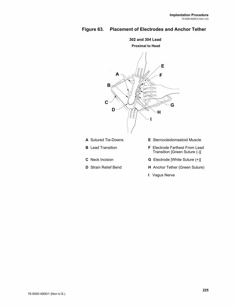
Implantation Procedure75-0000-8200/3 (Non-US)
Figure 63. Placement of Electrodes and Anchor Tether
302 and 304 Lead
Proximal to Head
A Sutured Tie-Downs E Sternocleidomastoid Muscle
B Lead Transition F Electrode Farthest From Lead Transition [Green Suture (-)]
C Neck Incision G Electrode [White Suture (+)]
D Strain Relief Bend H Anchor Tether (Green Suture)
I Vagus Nerve
A
B
C
E
F
G
H
I
D
22576-0000-4900/1 (Non-U.S.)

Implantation Procedure75-0000-8200/3 (Non-US)
303 Lead
12.6.4. Provide Strain Relief
Caution: Proper techniques for providing adequate strain relief below and above the sternocleidomastoid muscle are critical to the long-term success of the implant.
Caution: The lead wire has a potential for fracture if the recommended strain relief is not provided as described.
After attaching the two electrodes and the anchor tether, form a strain relief bend and a strain relief loop in the lead to provide adequate slack and allow for neck movement. 1. To form the strain relief bend [see Figure 53, Figure 64 (303
only), and Figure 65], do the following:
a. Form the lead body into a 3-cm (1.18 in) strain relief bend with at least 1 cm (.39 in) of lead routed parallel to the nerve. [303 lead only—Pay careful attention to the previously placed anchor tether and electrodes so they do not come unattached. Slight pressure may be placed against the anchor tether with a surgical instrument to ensure support to the anchor tether while the strain relief bend is being formed
Proximal to Head
A Lead Transition E Sternocleidomastoid Muscle
B Sutured Tie-Downs F Electrode Farthest From Lead Transition [Green Suture (-)]
C Neck Incision G Electrode [White Suture (+)]
D Strain Relief Bend H Anchor Tether (Green Suture)
I Vagus Nerve
A
B
C
D
I
H
G
F
E
22676-0000-4900/1 (Non-U.S.)
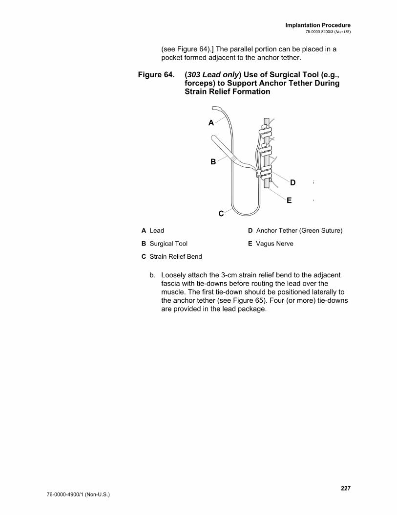
Implantation Procedure75-0000-8200/3 (Non-US)
(see Figure 64).] The parallel portion can be placed in a pocket formed adjacent to the anchor tether.
Figure 64. (303 Lead only) Use of Surgical Tool (e.g., forceps) to Support Anchor Tether During Strain Relief Formation
b. Loosely attach the 3-cm strain relief bend to the adjacent fascia with tie-downs before routing the lead over the muscle. The first tie-down should be positioned laterally to the anchor tether (see Figure 65). Four (or more) tie-downs are provided in the lead package.
A Lead D Anchor Tether (Green Suture)
B Surgical Tool E Vagus Nerve
C Strain Relief Bend
A
B
C
E
D
22776-0000-4900/1 (Non-U.S.)

Implantation Procedure75-0000-8200/3 (Non-US)
Caution: Sutures that are part of the lead coil are meant to assist in electrode placement around the left vagus nerve. These sutures should not be tied to each other since this may cause nerve damage (see Figure 65).
Caution: The lead and its electrodes are very delicate, and care should be taken not to over stretch or crush the helices.
Figure 65. Use of Tie-downs in Electrode Placement
302 and 304 Lead
Proximal to Head
Distal to Head
A Vagus Nerve E Suture
B Lead Body F Electrode [Green Suture (-)]
C Tie-Downs G Electrode [White Suture (+)]
D Strain Relief Bend H Anchor Tether (Green Suture)
A
B
C
D
E
F
G
H
22876-0000-4900/1 (Non-U.S.)

Implantation Procedure75-0000-8200/3 (Non-US)
303 Lead
Proximal to Head
Distal to Head
A Vagus Nerve E Suture
B Lead Body F Electrode [Green Suture (-)]
C Tie-Downs G Electrode [White Suture (+)]
D Strain Relief Bend H Anchor Tether (Green Suture)
A
B
C
D
E
F
G
H
22976-0000-4900/1 (Non-U.S.)
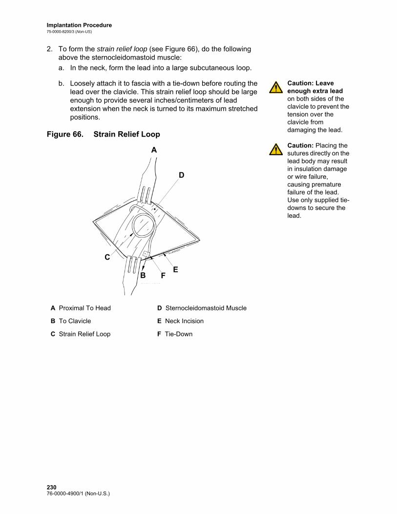
Implantation Procedure75-0000-8200/3 (Non-US)
2. To form the strain relief loop (see Figure 66), do the following above the sternocleidomastoid muscle:
a. In the neck, form the lead into a large subcutaneous loop.
Caution: Leave enough extra lead on both sides of the clavicle to prevent the tension over the clavicle from damaging the lead.
Caution: Placing the sutures directly on the lead body may result in insulation damage or wire failure, causing premature failure of the lead. Use only supplied tie-downs to secure the lead.
b. Loosely attach it to fascia with a tie-down before routing the lead over the clavicle. This strain relief loop should be large enough to provide several inches/centimeters of lead extension when the neck is turned to its maximum stretched positions.
Figure 66. Strain Relief Loop
A Proximal To Head D Sternocleidomastoid Muscle
B To Clavicle E Neck Incision
C Strain Relief Loop F Tie-Down
A
D
EFB
C
23076-0000-4900/1 (Non-U.S.)

Implantation Procedure75-0000-8200/3 (Non-US)
12.7. Connect the Lead to the Pulse Generator
To connect the lead directly to the pulse generator:
Caution: Do not use electrosurgical equipment after the pulse generator has been introduced to the sterile field. Exposure to this equipment may damage the pulse generator.
1. Look inside the pulse generator lead receptacle(s) to verify that no obstruction exists and that the setscrew(s) has been backed out adequately to allow full insertion of the connector pin(s). Avoid backing the setscrew(s) out further than needed for lead insertion (see Figure 67). The figure is intended to show the contrast between a blocked and a clear receptacle, and applies to single or dual pin headers.
Figure 67. Pulse Generator Receptacle and Setscrew
2. Keep the hex screwdriver perpendicular to the pulse generator. Insert the hex screwdriver through the center of the setscrew plug(s) to vent back pressure accumulated during lead insertion.
Caution: In the steps below, always push down on the hex screwdriver while turning it clockwise until it clicks (begins ratcheting) while ensuring that it is fully inserted in the setscrew. Also, the hex screwdriver must be inserted into the center of the silicone rubber setscrew plug and kept perpendicular to the pulse generator to avoid stripping the setscrew and/or dislodging the setscrew plug.
Caution: When using the hex screwdriver, grasp it by the handle only, as shown in Figure 68. Do not grasp any other portion of the hex screwdriver during use, as this may affect its proper function. Touching the metal shaft while the hex screwdriver is engaged with the setscrew can conduct an electrostatic discharge into the device circuitry and may damage the pulse generator.
A Receptacle Hole Clear
B Setscrew Visible (Manually back out)
A
B
23176-0000-4900/1 (Non-U.S.)
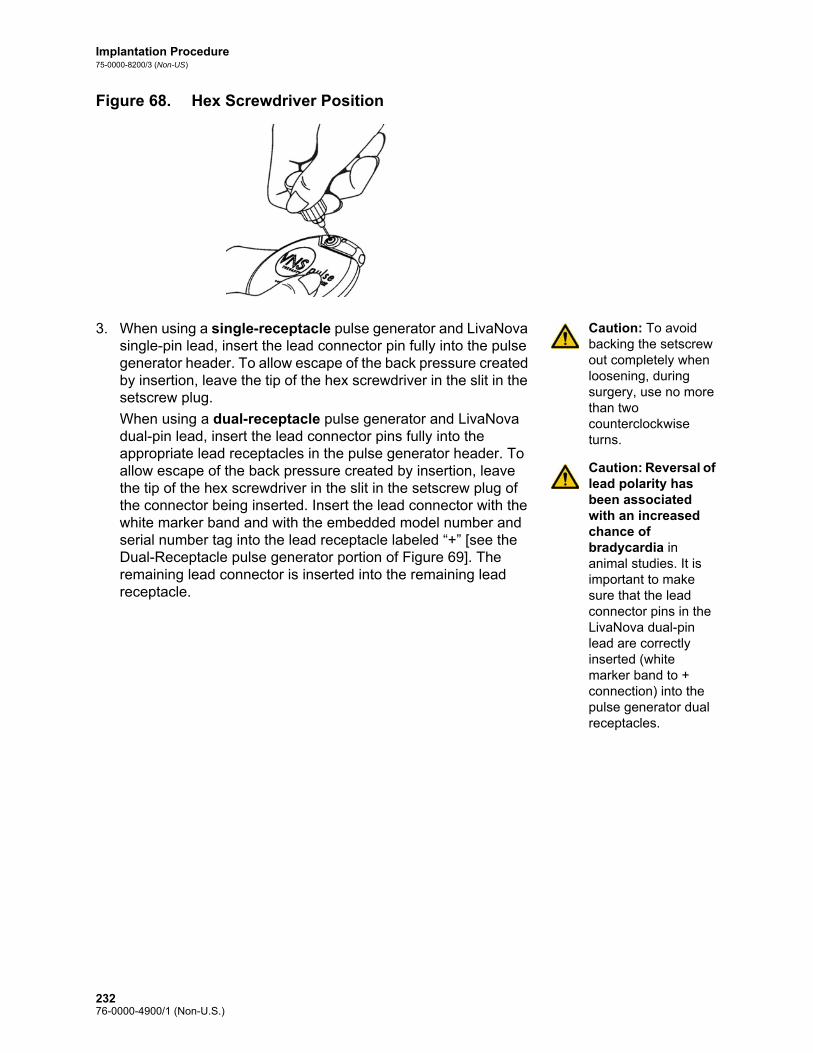
Implantation Procedure75-0000-8200/3 (Non-US)
Figure 68. Hex Screwdriver Position
Caution: To avoid backing the setscrew out completely when loosening, during surgery, use no more than two counterclockwise turns.
Caution: Reversal of lead polarity has been associated with an increased chance of bradycardia in animal studies. It is important to make sure that the lead connector pins in the LivaNova dual-pin lead are correctly inserted (white marker band to + connection) into the pulse generator dual receptacles.
3. When using a single-receptacle pulse generator and LivaNova single-pin lead, insert the lead connector pin fully into the pulse generator header. To allow escape of the back pressure created by insertion, leave the tip of the hex screwdriver in the slit in the setscrew plug.
When using a dual-receptacle pulse generator and LivaNova dual-pin lead, insert the lead connector pins fully into the appropriate lead receptacles in the pulse generator header. To allow escape of the back pressure created by insertion, leave the tip of the hex screwdriver in the slit in the setscrew plug of the connector being inserted. Insert the lead connector with the white marker band and with the embedded model number and serial number tag into the lead receptacle labeled “+” [see the Dual-Receptacle pulse generator portion of Figure 69]. The remaining lead connector is inserted into the remaining lead receptacle.
23276-0000-4900/1 (Non-U.S.)

Implantation Procedure75-0000-8200/3 (Non-US)
Figure 69. Lead Connector(s) Prior to Insertion and Fully Inserted
Single-Receptacle Pulse Generator
Prior to Insertion Fully Inserted
A Lead
B Suture Hole - Always suture to fascia
C Insert fully
A End of connector pin should be visible in cavity
B Be sure end of connector ring is inside of lead receptacle
Lead
BC
A
Be sure end of connector ring isinside of receptacle
A B
23376-0000-4900/1 (Non-U.S.)

Implantation Procedure75-0000-8200/3 (Non-US)
Dual-Receptacle Pulse Generator
4. With the hex screwdriver still inserted through the setscrew plug, verify that the connector pin is fully inserted. The pin should be visible in the area at the back end of the setscrew connector block. If it is not, remove the pin. To loosen the setscrew, engage the hex screwdriver into the setscrew, and turn it counterclockwise until the connector pin can be fully inserted. Avoid backing the setscrew out further than needed for lead insertion. If using the dual-receptacle pulse generator, repeat this procedure for each setscrew.
5. After verifying that the connector pin(s) has been fully inserted, tighten each setscrew by engaging the setscrew with the hex screwdriver and turning the hex screwdriver clockwise until it begins to click. Always push in on the hex screwdriver while turning it to ensure that the hex screwdriver is fully inserted in the setscrew.
Prior to Insertion Fully Inserted
A Lead
B Suture Hole - Always suture to fascia
C Insert Fully
A Make sure connector pins are fully inserted
B Serial Number Tag
C White Marker Band
Lead
P i I i F ll I
Fully Inserted
Suture Hole - Always suture toB C
A
A BMake sure connector pins are fully inserted
Serial Number Tag
White Marker Band
A
B
C C
23476-0000-4900/1 (Non-U.S.)

Implantation Procedure75-0000-8200/3 (Non-US)
Caution: It is important to do the following:
Ensure that the lead receptacle(s) is clean and free of obstruction.
Carefully insert the lead connector pin(s) into the lead receptacle(s) without bending the lead connector(s).
Visually inspect that the connector pin(s) is clean and completely inserted.
Electrical connection to the pulse generator is not established until the setscrew(s) is completely tightened with the hex screwdriver. Failure to make a good connection can result in HIGH impedance during a System Diagnostics (Lead Test) or erratic stimulation at varying intensity due to rapid, unpredictable changes in lead impedance, which is expected to adversely affect device effectiveness and may have serious safety consequences. Additionally, for Model 106 generators, sensing may be compromised.
Gently grasp and pull on lead connector boot(s) (the thick section of the lead) to verify the lead is properly secured inside the lead receptacle(s). Do not pull on lead body (thin section) or use excessive pull force, because doing so may cause lead damage.
12.8. Test the VNS Therapy System
Note: The programming wand should be placed into a sterile laser arm bag or equivalent (not provided by LivaNova) in order to introduce the programming wand into the sterile field. See the Programming Wand Physician’s Manual for more information.
The System Diagnostics (Lead Test), which should be conducted first, is performed with the lead and the pulse generator connected. Thus, if the System Diagnostics (Lead Test) is successful, both components are working properly. However, if the System Diagnostics (Lead Test) fails, either of the two components could be defective, or there may not be a good electrical connection between the pulse generator and the lead connector pin(s). If a defective component is suspected, disconnect the lead and perform the optional Generator Diagnostics (Pre-Implant Test), using the resistor assembly supplied with the accessory pack.
23576-0000-4900/1 (Non-U.S.)

Implantation Procedure75-0000-8200/3 (Non-US)
Caution: During the intraoperative System Diagnostics (Lead Test), infrequent incidents of bradycardia and/or asystole have occurred. If asystole, severe bradycardia (heart rate < 40 bpm), or a clinically significant change in heart rate is encountered during a System Diagnostics (Lead Test) or during initiation of stimulation, physicians should be prepared to follow guidelines consistent with Advanced Cardiac Life Support (ACLS).
Additionally, postoperative bradycardia can occur among patients with certain underlying cardiac arrhythmias. If a patient has experienced asystole, severe bradycardia (heart rate < 40 bpm), or a clinically significant change in heart rate during a System Diagnostics (Lead Test) at the time of initial device implantation, the patient should be placed on a cardiac monitor during initiation of stimulation.
The safety of this therapy has not been systematically established for patients experiencing bradycardia or asystole during VNS Therapy System implantation.
12.8.1. Model 102/102R System Diagnostics (Lead Test)
The System Diagnostics is performed when the lead and the pulse generator are connected. During intraoperative System Diagnostics, the pulse generator will deliver stimulation at 1 mA, 500 μsec for approximately 14 seconds.
Note: See the Programming Software Physician’s Manual for lead impedance details.
Caution: Electrical connection between the pulse generator and the lead connector pin(s) may be at fault.
To ensure proper system connection (impedance of the electrode-nerve interface), do the following:1. Verify that the lead impedance status is “OK.”
2. If lead impedance status is not “OK,” see the Troubleshooting chapter.
12.8.2. Model 103/104, 105 and 106 System Diagnostics
The System Diagnostics is performed when the lead and the pulse generator are connected. During intraoperative System Diagnostics, when the output current is set to 0 mA, the pulse generator will administer one brief pulse at 0.25 mA, 130 μsec and then deliver stimulation at 1 mA, 500 μsec for approximately 14 seconds. If the output current is programmed to any value > 0 mA, the System Diagnostics will administer one brief pulse at 0.25 mA, 130 μsec and then deliver the programmed output for the duration of the programmed ON time. The System Diagnostics is used intraoperatively to check the connection between the lead, the pulse generator, and the nerve.
If the System Diagnostics is successful (output current “OK” and lead impedance “OK”), both components are working properly.
23676-0000-4900/1 (Non-U.S.)

Implantation Procedure75-0000-8200/3 (Non-US)
Caution: Electrical connection between the pulse generator and the lead connector pin(s) may be at fault.
If the System Diagnostics fails (output current “LOW” or lead impedance “HIGH” or “LOW”), see the Troubleshooting chapter.
12.8.3. Generator Diagnostics (Pre-Implant Test)
The optional Generator Diagnostics is performed when the test resistor is attached to the pulse generator. When the System Diagnostics fails (lead impedance “HIGH” or “LOW”), the Generator Diagnostics can be used to determine whether the lead or the pulse generator is causing the problem. The Generator Diagnostics is performed with the test resistor that is included in the accessory pack. This test will verify that the pulse generator is functioning properly, independent of the lead.
To connect the test resistor to the pulse generator, perform these steps:1. Remove the lead connector pin(s) from the lead receptacles by
inserting the hex screwdriver through the center of the setscrew plug(s) and loosening the setscrew(s). Avoid backing out the setscrew(s) more than necessary to remove the lead. No more than a half-turn should be required to remove the lead.
Note: Fully insert the hex screwdriver into the setscrew and push in on the hex screwdriver whenever the setscrew(s) is being tightened or loosened.
2. Insert the connector pin(s) of the resistor assembly into the lead receptacle(s). Be careful while inserting the test resistor pin(s) into the lead receptacle(s). If binding or significant resistance is felt, remove the test resistor, inspect it, and clean it if necessary. Without the use of excessive force, reinsert the test resistor.
3. When the resistor assembly is in place, tighten the setscrew(s) until the hex screwdriver begins to click (see Figure 70). Again, always push in on the hex screwdriver while turning it to ensure that the hex screwdriver is fully inserted in the setscrew.
23776-0000-4900/1 (Non-U.S.)

Implantation Procedure75-0000-8200/3 (Non-US)
Figure 70. Connect the Resistor Assembly
Note: See the Programming Software Physician’s Manual for details.
4. Perform the Generator Diagnostics (Pre-Implant Test).
If the Generator Diagnostics (Pre-Implant Test) is successful (lead impedance “OK”), the pulse generator is working properly.
If the Generator Diagnostics fails (lead impedance “HIGH” or “LOW”), see the Troubleshooting chapter.
If the component is damaged, contact LivaNova and return the item (following the disinfection procedure described in the “Precautions” section of the Introduction to the VNS Therapy System chapter), along with a completed Returned Product Form.
12.8.4. Optional Monitoring
Optional physiologic monitoring of VNS Therapy System operation may be done if surgery is performed under local anesthesia. Monitor the patient’s voice for signs of hoarseness while gradually increasing the pulse generator output current. After performing the System Diagnostics and obtaining successful results, reset the current to 0.0 mA.
12.8.5. Model 106 Heart Beat Detection and Seizure Detection Configuration
After the diagnostic testing has been completed, configure the heart beat detection and seizure detection functions (Model 106 only):1. Place the Model 106 pulse generator in the chest pocket, coiling
the remaining slack of the lead and placing it to the side of the
Single-Receptacle Pulse Generator
Dual-Receptacle Pulse Generator
A Setscrew Plug C Setscrew Plugs (2)
B Resistor Assembly D Resistor Assembly
A
B
C
D
23876-0000-4900/1 (Non-U.S.)

Implantation Procedure75-0000-8200/3 (Non-US)
generator. The generator can be placed with either side facing outward.
2. Use the programming software to select the “Seizure Detection” tab and turn Seizure Detection “ON”.
3. Use the following method to select a patient-specific Heartbeat Detection (sensitivity) value:
Note: To determine R-wave amplitude, see Step 6 in the Section called “(Model 106 generator only) Determine acceptable device implant locations”.
Average the two R-wave amplitude measurements obtained from the positional assessment. If this information is not available go to Step 7.
Map the average R-wave amplitude value to the appropriate Heartbeat Detection setting in Table 49 and select this value in the programming software.
Table 49. Heartbeat Detection Mapping
4. The programming software will display the heart rate detected by the Model 106 generator for 2 minutes after a new Heartbeat Detection setting is programmed. The process will automatically stop after 2 minutes, or you may manually stop the process by programming “Stop”. Place the programming wand over the pulse generator and select “Program”.
5. Verify the changes by pressing “Confirm” and then “Start Programming”.
6. Use the ECG monitor to compare the heart beat reported on the programming computer with that reported by the ECG monitor. If heartbeat detection is accurate, go to Step 9, Otherwise, go to Step 7.
7. If heartbeat detection is inaccurate in Step 6, or if the information from the R-wave amplitude positional assessment is not available, select a value of “1” from the Heartbeat Detection parameter list (1-5) and repeat programming steps 4 - 5.
8. Monitor and compare the heartbeat reported on the programming computer with that reported by the ECG monitor, and repeat Steps 4 - 5, as necessary, to test or configure other
Heartbeat Detection
Average Amplitude (mV)(across different postures)
Minimum Maximum
5 0.40 0.50
4 0.51 0.70
3 0.71 0.85
2 0.86 1.25
1 1.26 --
23976-0000-4900/1 (Non-U.S.)
Implantation Procedure75-0000-8200/3 (Non-US)
Heartbeat Detection settings (settings 2,3,4,5) until the device accurately detects heartbeats. If more than one heartbeat detection setting results in accurate detection of heart beats, select the lesser of these detection settings.
Note: Steps 9-10 — Seizure detection can also be configured post-operatively.
9. Select the Threshold for AutoStim as appropriate (70%-least sensitive, 20%-most sensitive).
10. Select “Program” and “Confirm”.
11. After configuration, proceed to “Complete the Implantation Procedure”, step 2.
12.9. Complete the Implantation Procedure
After the testing has been completed, finish the implantation procedure:
Caution: Do not place the lead slack under the pulse generator, because doing so could result in insulation failure and system malfunction.
Caution: This suturing is important to stabilize the pulse generator and to prevent manipulation by the patient, which could damage the lead wires.
Caution: Do not place the sutures directly around the body of the lead; this could result in insulation failure and system malfunction, and possible lead breakage.
1. Place the pulse generator in the chest pocket, coiling the remaining slack of the lead and placing it to the side of the pulse generator. The pulse generator can be placed with either side facing outward.
2. Secure the pulse generator by placing a suture through the suture hole and attaching it to fascia (not to muscle).
3. Perform the second System Diagnostics and verify lead impedance status remains “OK.”
4. Interrogate the pulse generator to verify that Normal Mode, Magnet Mode and AutoStim Mode (106 generator only) output is 0 mA.
Output current (mA): 0
Magnet current (mA): 0
AutoStim current (mA): 0
Caution: Do not program the pulse generator to an ON or periodic stimulation treatment for at least 14 days after the initial or replacement implantation. Failure to observe this precaution may result in patient discomfort or adverse events.
5. LivaNova recommends irrigation of both incision sites with generous amounts of bacitracin or equivalent solution before closure.
6. Close the surgical incisions. Use cosmetic closure techniques to minimize scarring.
7. Administer antibiotics postoperatively (at the discretion of the physician).
A neck brace can be used by the patient for the first week to help ensure proper lead stabilization.
24076-0000-4900/1 (Non-U.S.)

Implantation Procedure75-0000-8200/3 (Non-US)
12.9.1. Patient Identification
Included with the pulse generator is an Implant Warranty and Registration Card that must be completed and the top, white copy returned to LivaNova. This information, as required by government agencies, becomes part of LivaNova’s registry of implantees and is used as a permanent record of implant recipient information. Additionally, the patient should be given a Patient Essentials kit, which contains magnets, patient’s manuals, and wallet-sized Patient Emergency Information Cards that contain information about the VNS Therapy System. The patient should be instructed to carry this card at all times.
24176-0000-4900/1 (Non-U.S.)

Implantation Procedure75-0000-8200/3 (Non-US)
24276-0000-4900/1 (Non-U.S.)

Revision / Replacement / Removal Procedure
VNS Therapy® System
24376-0000-4900/1 (Non-U.S.)
Revision / Replacement / Removal Procedure75-0000-8400/1 (Non-US)
13. REVISION / REPLACEMENT / REMOVAL PROCEDURE__________
13.1. Introduction
Note: Cyberonics requests the return of any explanted or opened and unused component(s) of the VNS Therapy System to the company. A Return Product Kit is available from Clinical Technical Services at 1 (866) 882-8804 (U.S. and Canada), +1 (281) 228-7330 (Worldwide), or +32 2 790 27 73 (Europe/EMMEA).
Revision, replacement, or removal of the VNS Therapy System or any component of the system may be desired for several reasons: Replacement of the pulse generator may be required due to
pending End-of-Service of the pulse generator or if End-of-Service has been reached and the pulse generator cannot communicate or provide therapy.
Revision/replacement of the lead may be necessary if a broken or damaged lead is suspected, based on diagnostic testing or x-ray evaluation.
Removal of the VNS Therapy System may be required in cases of infection or for certain medical procedures (e.g., MRI) contraindicated by the labeling (see the Introduction to the VNS Therapy System chapter).
The following instructions are intended to be general guidelines. If you have questions about the procedures, contact Clinical Technical Services (CTS) at 1 (866) 882-8804 (U.S. and Canada), +1 (281) 228-7330 (Worldwide), or +32 2 790 27 73 (Europe/EMMEA).
13.2. VNS Therapy Components and Surgical Materials
The following materials should be available before performing a revision of any component of the VNS Therapy System.
13.2.1. Dual-Receptacle Pulse Generator Replacement
Primary and backup dual-receptacle pulse generators
Two backup single-receptacle pulse generators
13.2.2. Single-Receptacle Pulse Generator Replacement
Primary and backup single-receptacle pulse generators
24476-0000-4900/1 (Non-U.S.)

Revision / Replacement / Removal Procedure75-0000-8400/1 (Non-US)
13.2.3. Other Necessary VNS Therapy Components and Surgical Materials
Note: Revision surgeries involving dual-pin leads require the availability of a new single-pin lead, and both single-receptacle and dual-receptacle pulse generators.
Primary and backup single-pin leads
Tunneler
Accessory pack
Programming system
Sterile laser arm bag or equivalent (not provided by Cyberonics)
Soft vessel loops or silicone sheet (not provided by Cyberonics)
13.3. VNS Therapy System Revisions
For all revision surgeries, the patient should consent pre-operatively to receiving a new pulse generator and new lead in case either is damaged during the revision surgery.
13.3.1. Procedure - Replacement of the Pulse Generator
13.3.1.1. Pre-operative steps
Note: For detailed information about Systems Diagnostics, see “Test the VNS Therapy System” in the Implantation Procedure chapter.
1. Use the programming system to interrogate the existing pulse generator and perform System Diagnostics (Lead Test) before the patient enters the OR.
2. Cyberonics recommends that the surgeon review an x-ray of the pulse generator to determine the routing of the lead. This helps to avoid inadvertent damage to the lead during dissection to remove the pulse generator.
3. If System Diagnostics results indicate “HIGH” or “LOW” lead impedance or the x-ray review shows a gross discontinuity in the lead [lead break or pin(s) disconnected], proceed to “Procedure – Replacement of the VNS Therapy Lead”.
Note: If the replacement generator is a Model 106, the existing generator pocket location may need to be revised.
4. If System Diagnostics results indicate “OK” lead impedance, use the programming system, outside the sterile field in the OR, to interrogate the replacement pulse generator. This ensures clear communication.
5. If the replacement generator is a Model 106, verify that the existing generator implant location satisfies the requirements outlined in the “(Model 106 generator only) Determine acceptable device implant locations” section of the Implantation Procedure chapter. If the existing implant location does not satisfy the outlined requirements, use the same procedure to identify a suitable location close to the original implant site to place the new Model 106 generator.
6. Program the patient data into the new pulse generator.
24576-0000-4900/1 (Non-U.S.)
Revision / Replacement / Removal Procedure75-0000-8400/1 (Non-US)
13.3.1.2. Intra-operative steps
Caution: Do not use electrosurgical equipment after the new pulse generator has been introduced to the sterile field. Exposure to this equipment may damage the pulse generator.
1. With the lead pin(s) still connected, remove the existing pulse generator from the pocket.
Note: Extraneous pocket space left behind from the replacement of a larger pulse generator with a smaller pulse generator may increase the likelihood of certain adverse events (e.g., seroma, device manipulation, and device migration).
Note: Replacement of a smaller pulse generator with a larger pulse generator may require enlargement of the generator pocket during surgery. Physicians should assess the potential impact to post-surgical recovery time and likelihood of temporary patient discomfort due to surgical alteration of the generator pocket.
Caution: When using the hex screwdriver, grasp it by the handle only. Touching the metal shaft while the hex screwdriver is engaged with the setscrew can conduct an electrostatic discharge into the device circuitry and may damage the pulse generator.
2. Open the new pulse generator package. Use the hex screwdriver to disconnect the existing pulse generator from the implanted lead. Remove the lead connector pin(s) from the lead receptacles by inserting the hex screwdriver through the center of the setscrew plug(s) and loosening the setscrew(s). Avoid backing out the setscrew(s) more than necessary to remove the lead. No more than half a turn should be required to remove the lead.
3. Connect the replacement pulse generator to the lead following the steps in the “Connect the Lead to the Pulse Generator” section in the Implantation Procedure chapter and complete the remainder of the implantation procedure.
Note: Consult the prescribing physician before the surgery to determine parameter settings following placement of the new pulse generator.
13.3.2. Procedure – Replacement of the VNS Therapy Lead
13.3.2.1. Pre-operative steps
1. Use the programming system to interrogate the existing pulse generator and perform System Diagnostics (Lead Test) before the patient enters the OR. Cyberonics recommends that the surgeon review x-rays to confirm the existence of a lead discontinuity [lead break or pin(s) disconnected], if possible.
2. If System Diagnostics results indicate “OK” lead impedance, there is no gross discontinuity in the lead from the x-ray review, and a short-circuit condition is not suspected, the implanted lead is functioning properly. Reassess proceeding with surgery or, if replacement of the pulse generator is still desired, proceed to “Procedure - Replacement of the Pulse Generator”.
3. If System Diagnostic results indicate “HIGH” or “LOW” lead impedance or a gross lead discontinuity is observed, surgical intervention is required. Use the programming system, outside the sterile field in the OR, to interrogate all potential
24676-0000-4900/1 (Non-U.S.)

Revision / Replacement / Removal Procedure75-0000-8400/1 (Non-US)
replacement pulse generators. This ensures clear device communication.
4. If the replacement generator is a Model 106, verify that the existing generator implant location satisfies the requirements outlined in the “(Model 106 generator only) Determine acceptable device implant locations” section of the Implantation Procedure chapter. If the existing implant location does not satisfy the outlined requirements, use the same procedure to identify a suitable location close to the original implant site to place the new Model 106 generator.
5. Proceed to “Intra-operative steps” below.
13.3.2.2. Intra-operative steps
Note: For complete troubleshooting steps, see the “Troubleshooting” section of the Programming Software Physician’s Manual.
13.3.2.2.1. “HIGH” lead impedance on System Diagnostics
If “HIGH” lead impedance is reported, perform the following steps:1. With lead pin(s) still connected, remove the existing pulse
generator from the pocket.
2. Open the accessory pack and remove the hex screwdriver and test resistor.
3. Remove the lead connector pin(s) from the lead receptacle(s) by inserting the hex screwdriver through the center of the setscrew plug(s) and loosening the setscrew(s). Avoid backing out the setscrew(s) more than necessary to remove the lead. No more than a half turn should be required to remove the lead.
4. If foreign material (e.g., blood) is observed in the pulse generator receptacle(s), flush the receptacle(s) with saline to remove the foreign material. Drain the excess fluid from the receptacle(s). Do not place any object (other than the connector pin) into the receptacle. Use saline to clean the lead connector pin(s), then wipe dry.
Note: For proper lead insertion techniques, see “Connect the Lead to the Pulse Generator” in the Implantation Procedure chapter.
5. Re-insert the existing lead connector pin(s) into the existing pulse generator following proper lead insertion techniques.
Caution: Visually inspect that the connector pin(s) is clean and completely inserted.
6. Introduce the programming system into the sterile field with a sterile laser arm bag (or equivalent) and perform an interrogation followed by System Diagnostics.
7. Record System Diagnostics results.
If the results indicate “OK” lead impedance, the previous “HIGH” lead impedance was resolved and the system appears to be functioning properly. Assess replacement of the pulse generator.
If replacement of the generator is not desired, verify that all relevant steps outlined in “Test the VNS Therapy System”
24776-0000-4900/1 (Non-U.S.)

Revision / Replacement / Removal Procedure75-0000-8400/1 (Non-US)
section of the Implantation Procedure chapter have been completed. Finish the procedure by following the steps in “Complete the Implantation Procedure” section in the Implantation Procedure chapter.
Note: The prescribing physician will program the stimulation parameters post-operatively based on the patient’s tolerance to the stimulation.
If replacement of the pulse generator is desired, open a new compatible pulse generator package. Connect the replacement pulse generator to the lead following the steps in the “Connect the Lead to the Pulse Generator” section in the Implantation Procedure chapter and complete the remainder of the implantation procedure. Ensure appropriate patient data has been programmed into the new generator.
If System Diagnostics results continue to report “HIGH” lead impedance, perform Generator Diagnostics (Pre-Implant Test) with the test resistor assembly from the accessory pack to verify that the pulse generator is functioning properly, independent of the lead. To perform Generator Diagnostics, follow the steps in “Generator Diagnostics (Pre-Implant Test)” below.
Note: For complete troubleshooting steps see the “Troubleshooting” section of the Programming Software Physician’s Manual.
13.3.2.2.2. “LOW” lead impedance on System Diagnostics
If System Diagnostics report “LOW” lead impedance, perform Generator Diagnostics (Pre-Implant Test) with the test resistor assembly from the accessory pack to verify that the pulse generator is functioning properly, independent of the lead.
To perform Generator Diagnostics (Pre-Implant Test), follow the steps in “Generator Diagnostics (Pre-Implant Test)” below.
13.3.2.3. Generator Diagnostics (Pre-Implant Test)
1. Insert the connector pin(s) of the resistor assembly into the lead receptacle(s). Be careful while inserting the test resistor pin(s) into the lead receptacle(s). If binding or significant resistance is felt, remove the test resistor, inspect it, and clean it if necessary. Without the use of excessive force, reinsert the test resistor.
2. When the resistor assembly is in place, tighten the setscrew(s) until the hex screwdriver begins to click (see Figure 71). Always push in on the hex screwdriver while turning it to ensure that the hex screwdriver is fully inserted in the setscrew.
24876-0000-4900/1 (Non-U.S.)

Revision / Replacement / Removal Procedure75-0000-8400/1 (Non-US)
Figure 71. Connect the Resistor Assembly
Note: For details, see the VNS Therapy Programming Software Physician’s Manual.
3. Perform Generator Diagnostics (Pre-Implant Test).
If Generator Diagnostics results indicate “HIGH” or “LOW” lead impedance, call Cyberonics’ CTS at 1 (866) 882-8804 (U.S. and Canada), +1 (281) 228-7330 (Worldwide), or +32 2 790 27 73 (Europe/EMMEA).
If Generator Diagnostics results indicate “OK” lead impedance, the implanted lead should be replaced and Generator replacement assessed.
Models 102, 103, 105, 106
A Setscrew Plug
B Resistor Assembly
Models 102R and 104
C Setscrew Plugs (2)
D Resistor Assembly
A
B
C
D
24976-0000-4900/1 (Non-U.S.)

Revision / Replacement / Removal Procedure75-0000-8400/1 (Non-US)
Caution: Lead replacement or removal is a medical judgement that must be carefully weighed against the known and unknown risks of surgery. At present there are no known long-term hazards or risks associated with leaving the lead implanted, beyond those mentioned in this physician’s manual.
Note: Full body MRI is possible with ≤ 2 cm remaining.
13.3.2.4. Remove existing helices and lead
1. Open the neck incision and locate the vagus nerve/helices interface.
2. Assess the degree of fibrotic encapsulation to determine if the entire lead can be removed safely.
If removal of the existing helices can be accomplished, the new helices may be placed in the same location.
If complete removal of the helices from the nerve is not possible, transect as much of the lead as possible. With ≤ 2 cm of the lead remaining (see Figure 72) a full body MRI using the body coil to transmit RF is allowable. (See the MRI with the VNS Therapy System chapter for further details.).
If it is not possible to leave ≤ 2 cm, then MRI can still be performed for brain or extremity imaging with the appropriate type of T/R coil. (See the MRI with the VNS Therapy System chapter for further details.).
Figure 72. Transected Lead (≤ 2 cm)
3. The replacement helices can be placed above or below the existing helices if they must remain.
25076-0000-4900/1 (Non-U.S.)

Revision / Replacement / Removal Procedure75-0000-8400/1 (Non-US)
13.3.2.5. Complete the procedure
Note: The prescribing physician will program the stimulation parameters post-operatively after the recommended 2-week recovery period to allow the nerve to heal.
Complete the remainder of the implant procedure per the Implantation Procedure chapter, starting with the steps in the “Implant the lead” section. Pay particular attention to all cautions and warnings regarding the cardiac branches.
13.4. Removal of the VNS Therapy System
If removal is medically necessary, Cyberonics recommends removing as much of the VNS Therapy System as can be safely accomplished: Assess the degree of fibrotic in-growth in and around the
helices.
Remove the entire system, if possible.
If fibrotic encapsulation hinders safe removal of the entire system, transect as much of the lead wire as possible (see Figure 72).
Note: For detailed information, see the MRI with the VNS Therapy System chapter.
Note: For detailed information regarding the use of diathermy with VNS, see the Introduction to the VNS Therapy System chapter.
Removal of the pulse generator alone does not alter the hazards associated with certain MRI procedures.
Diathermy procedures are contraindicated for patients with any portion of the VNS Therapy System remaining in the body.
25176-0000-4900/1 (Non-U.S.)
Revision / Replacement / Removal Procedure75-0000-8400/1 (Non-US)
25276-0000-4900/1 (Non-U.S.)

Information and Support
253 76-0000-4900/1 (Non-U.S.)

Information and Support75-0000-1600/5 (Worldwide)
14. INFORMATION AND SUPPORT ___________________________
If there are questions regarding use of the VNS Therapy System or any of its accessories, contact LivaNova:
ManufacturerLivaNova USA, Inc.100 Cyberonics BoulevardHouston, Texas 77058USA
Tel: +1 (281) 228-72001 (800) 332-1375 (US and Canada)
Fax: +1 (281) 218-9332
Authorized Representative EuropeLivaNova Belgium NVIkaroslaan 831930 Zaventem, Belgium
Tel: +32.2.720.95.93 Fax: +32.2.720.60.53
24-hour Clinical Technical SupportTel: 1 (866) 882-8804 (US and Canada)
+1 (281) 228-7330 (Worldwide)+32 2 790 27 73 (Europe/EMMEA)
Internet www.livanova.com
25476-0000-4900/1 (Non-U.S.)
Appendices
Battery Longevity and Programmed Setting Choicesfor Model 103/104,105 and 106 Generators
Non-US Version
25576-0000-4900/1 (Non-U.S.)

Appendices75-0000-2800/0 (Non-US)
15. APPENDICES
15.1. Appendix A — Model 103/104 Battery Longevity and Programmed Setting Choices
Parameters at 3kOhms
(M103/104)
Time from BOL* to IFITime from IFI to N
EOSTime from N EOS to
EOS
10% Duty Cycle
33% Duty Cycle
50% Duty Cycle
10% Duty Cycle
33% Duty Cycle
50% Duty Cycle
10% Duty Cycle
33% Duty Cycle
50% Duty Cycle
mA Hz μS Years Years Years Years Years Years Years Years Years
0.5 10 130 >10 >10 >10 2.8 2.5 2.4 2.2 2.0 1.9
0.5 15 130 >10 >10 >10 2.7 2.2 1.9 2.1 1.7 1.5
0.5 20 130 >10 >10 >10 2.5 1.9 1.7 2.0 1.5 1.3
0.5 25 130 >10 >10 >10 2.4 1.7 1.4 1.9 1.4 1.2
0.5 30 130 >10 >10 9.5 2.3 1.6 1.3 1.8 1.3 1.0
0.5 10 250 >10 >10 >10 2.7 2.3 2.0 2.1 1.8 1.6
0.5 15 250 >10 >10 >10 2.5 1.9 1.6 2.0 1.5 1.3
0.5 20 250 >10 >10 >10 2.4 1.7 1.4 1.9 1.3 1.1
0.5 25 250 >10 >10 8.7 2.3 1.5 1.2 1.8 1.2 0.9
0.5 30 250 >10 9.8 7.6 2.1 1.3 1.0 1.7 1.0 0.8
0.5 10 500 >10 >10 >10 2.5 1.9 1.6 1.9 1.5 1.2
0.5 15 500 >10 >10 8.9 2.3 1.5 1.2 1.8 1.2 0.9
0.5 20 500 >10 9.3 7.2 2.1 1.2 1.0 1.6 1.0 0.8
0.5 25 500 >10 8.1 6.1 1.9 1.1 0.8 1.5 0.9 0.6
0.5 30 500 >10 7.1 5.2 1.8 0.9 0.7 1.4 0.8 0.6
0.5 10 750 >10 >10 9.4 2.3 1.6 1.3 1.8 1.2 1.0
0.5 15 750 >10 9.1 7.0 2.1 1.2 0.9 1.6 1.0 0.7
0.5 20 750 >10 7.5 5.6 1.9 1.0 0.7 1.5 0.8 0.6
0.5 25 750 >10 6.4 4.7 1.7 0.9 0.6 1.3 0.7 0.5
0.5 30 750 >10 5.5 4.0 1.5 0.7 0.5 1.2 0.6 0.4
0.5 10 1000 >10 >10 7.9 2.2 1.4 1.1 1.7 1.1 0.8
0.5 15 1000 >10 7.7 5.8 1.9 1.0 0.8 1.5 0.8 0.6
0.5 20 1000 >10 6.3 4.6 1.7 0.8 0.6 1.3 0.7 0.5
25676-0000-4900/1 (Non-U.S.)

Appendices75-0000-2800/0 (Non-US)
0.5 25 1000 >10 5.3 3.8 1.5 0.7 0.5 1.2 0.6 0.4
0.5 30 1000 >10 4.6 3.2 1.4 0.6 0.4 1.1 0.5 0.3
1 10 130 >10 >10 >10 2.6 2.1 1.9 2.0 1.5 1.3
1 15 130 >10 >10 >10 2.5 1.9 1.6 1.9 1.4 1.1
1 20 130 >10 >10 >10 2.4 1.6 1.3 1.8 1.2 0.9
1 25 130 >10 >10 9.3 2.2 1.5 1.2 1.7 1.1 0.8
1 30 130 >10 >10 8.2 2.1 1.3 1.0 1.6 1.0 0.8
1 10 250 >10 >10 >10 2.4 1.7 1.4 1.8 1.3 1.0
1 15 250 >10 >10 8.9 2.2 1.4 1.1 1.7 1.1 0.9
1 20 250 >10 9.4 7.2 2.1 1.2 0.9 1.6 0.9 0.7
1 25 250 >10 8.1 6.1 1.9 1.1 0.8 1.5 0.8 0.6
1 30 250 >10 7.1 5.3 1.8 0.9 0.7 1.4 0.7 0.5
1 10 500 >10 >10 7.9 2.1 1.2 1.0 1.5 0.9 0.7
1 15 500 >10 7.8 5.8 1.8 1.0 0.7 1.4 0.7 0.5
1 20 500 >10 6.3 4.6 1.6 0.8 0.6 1.2 0.6 0.4
1 25 500 >10 5.3 3.8 1.5 0.7 0.5 1.1 0.5 0.4
1 30 500 >10 4.6 3.2 1.3 0.6 0.4 1.0 0.4 0.3
1 10 750 >10 8.0 6.0 1.8 1.0 0.7 1.3 0.7 0.5
1 15 750 >10 6.0 4.3 1.5 0.7 0.5 1.1 0.5 0.4
1 20 750 >10 4.7 3.4 1.3 0.6 0.4 1.0 0.4 0.3
1 25 750 9.3 3.9 2.8 1.2 0.5 0.3 0.9 0.4 0.3
1 30 750 8.3 3.4 2.3 1.1 0.4 0.3 0.8 0.3 0.2
1 10 1000 >10 6.6 4.9 1.6 0.8 0.6 1.2 0.5 0.4
1 15 1000 >10 4.8 3.4 1.3 0.6 0.4 1.0 0.4 0.3
1 20 1000 9.0 3.8 2.7 1.1 0.5 0.3 0.8 0.3 0.2
1 25 1000 7.8 3.1 2.2 1.0 0.4 0.3 0.7 0.3 0.2
1 30 1000 6.9 2.7 1.8 0.9 0.3 0.2 0.6 0.2 0.2
1.5 10 130 >10 >10 8.8 2.2 1.4 1.1 1.6 1.0 0.8
Parameters at 3kOhms
(M103/104)
Time from BOL* to IFITime from IFI to N
EOSTime from N EOS to
EOS
10% Duty Cycle
33% Duty Cycle
50% Duty Cycle
10% Duty Cycle
33% Duty Cycle
50% Duty Cycle
10% Duty Cycle
33% Duty Cycle
50% Duty Cycle
mA Hz μS Years Years Years Years Years Years Years Years Years
25776-0000-4900/1 (Non-U.S.)

Appendices75-0000-2800/0 (Non-US)
1.5 15 130 >10 >10 7.9 2.1 1.3 1.0 1.6 0.9 0.7
1.5 20 130 >10 9.3 7.1 2.0 1.1 0.9 1.5 0.8 0.6
1.5 25 130 >10 8.3 6.3 1.9 1.0 0.8 1.4 0.7 0.5
1.5 30 130 >10 7.6 5.7 1.8 0.9 0.7 1.3 0.6 0.5
1.5 10 250 >10 >10 8.8 2.1 1.3 1.0 1.5 0.8 0.6
1.5 15 250 >10 8.9 6.8 1.9 1.0 0.8 1.3 0.7 0.5
1.5 20 250 >10 7.5 5.6 1.7 0.9 0.6 1.2 0.6 0.4
1.5 25 250 >10 6.4 4.7 1.6 0.8 0.5 1.1 0.5 0.4
1.5 30 250 >10 5.6 4.0 1.4 0.7 0.5 1.0 0.5 0.3
1.5 10 500 >10 7.3 5.4 1.7 0.8 0.6 1.2 0.6 0.4
1.5 15 500 >10 5.7 4.1 1.4 0.7 0.5 1.0 0.4 0.3
1.5 20 500 >10 4.7 3.3 1.2 0.5 0.4 0.9 0.4 0.2
1.5 25 500 9.2 3.9 2.7 1.1 0.4 0.3 0.8 0.3 0.2
1.5 30 500 8.2 3.3 2.3 1.0 0.4 0.3 0.7 0.3 0.2
1.5 10 750 >10 5.3 3.8 1.4 0.6 0.4 0.9 0.4 0.3
1.5 15 750 9.5 4.1 2.9 1.1 0.5 0.3 0.8 0.3 0.2
1.5 20 750 8.1 3.3 2.3 1.0 0.4 0.3 0.6 0.2 0.2
1.5 25 750 7.0 2.7 1.9 0.8 0.3 0.2 0.6 0.2 0.1
1.5 30 750 6.2 2.3 1.6 0.7 0.3 0.2 0.5 0.2 0.1
1.5 10 1000 9.7 4.2 3.0 1.1 0.5 0.3 0.8 0.3 0.2
1.5 15 1000 7.8 3.1 2.2 0.9 0.4 0.2 0.6 0.2 0.2
1.5 20 1000 6.5 2.5 1.7 0.8 0.3 0.2 0.5 0.2 0.1
1.5 25 1000 5.6 2.1 1.4 0.7 0.2 0.2 0.4 0.2 0.1
1.5 30 1000 4.9 1.8 1.2 0.6 0.2 0.1 0.4 0.1 0.1
2 10 130 >10 8.7 6.6 1.9 1.1 0.8 1.4 0.7 0.5
2 15 130 >10 7.2 5.3 1.7 0.9 0.6 1.2 0.6 0.4
2 20 130 >10 6.2 4.5 1.6 0.8 0.5 1.1 0.5 0.4
2 25 130 >10 5.5 4.0 1.4 0.7 0.5 1.0 0.5 0.3
Parameters at 3kOhms
(M103/104)
Time from BOL* to IFITime from IFI to N
EOSTime from N EOS to
EOS
10% Duty Cycle
33% Duty Cycle
50% Duty Cycle
10% Duty Cycle
33% Duty Cycle
50% Duty Cycle
10% Duty Cycle
33% Duty Cycle
50% Duty Cycle
mA Hz μS Years Years Years Years Years Years Years Years Years
25876-0000-4900/1 (Non-U.S.)

Appendices75-0000-2800/0 (Non-US)
2 30 130 >10 5.0 3.5 1.3 0.6 0.4 1.0 0.4 0.3
2 10 250 >10 6.4 4.7 1.6 0.8 0.6 1.2 0.5 0.4
2 15 250 >10 5.2 3.8 1.4 0.6 0.4 1.0 0.4 0.3
2 20 250 >10 4.4 3.1 1.2 0.5 0.4 0.9 0.4 0.3
2 25 250 9.1 3.8 2.7 1.1 0.5 0.3 0.8 0.3 0.2
2 30 250 8.3 3.4 2.3 1.0 0.4 0.3 0.7 0.3 0.2
2 10 500 9.5 4.1 2.9 1.2 0.5 0.3 0.8 0.3 0.2
2 15 500 7.8 3.1 2.2 1.0 0.4 0.3 0.7 0.3 0.2
2 20 500 6.7 2.6 1.8 0.8 0.3 0.2 0.6 0.2 0.1
2 25 500 5.9 2.2 1.5 0.7 0.3 0.2 0.5 0.2 0.1
2 30 500 5.2 1.9 1.3 0.6 0.2 0.1 0.4 0.1 0.1
2 10 750 7.5 2.9 2.0 0.9 0.3 0.2 0.6 0.2 0.2
2 15 750 5.9 2.2 1.5 0.7 0.3 0.2 0.5 0.2 0.1
2 20 750 5.0 1.8 1.2 0.6 0.2 0.1 0.4 0.1 0.1
2 25 750 4.3 1.5 1.0 0.5 0.2 0.1 0.3 0.1 0.1
2 30 750 3.7 1.3 0.9 0.4 0.1 0.1 0.3 0.1 0.1
2 10 1000 6.1 2.3 1.6 0.7 0.3 0.2 0.5 0.2 0.1
2 15 1000 4.7 1.7 1.1 0.6 0.2 0.1 0.4 0.1 0.1
2 20 1000 3.9 1.3 0.9 0.5 0.2 0.1 0.3 0.1 0.1
2 25 1000 3.3 1.1 0.8 0.4 0.1 0.1 0.3 0.1 0.1
2 30 1000 2.9 1.0 0.6 0.3 0.1 0.1 0.2 0.1 0.0
2.5 10 130 >10 7.2 5.3 1.7 0.9 0.6 1.3 0.6 0.5
2.5 15 130 >10 6.0 4.4 1.5 0.7 0.5 1.1 0.5 0.4
2.5 20 130 >10 5.1 3.7 1.4 0.6 0.4 1.0 0.4 0.3
2.5 25 130 >10 4.5 3.2 1.2 0.5 0.4 0.9 0.4 0.3
2.5 30 130 9.3 4.0 2.8 1.1 0.5 0.3 0.8 0.3 0.2
2.5 10 250 >10 5.4 3.9 1.4 0.6 0.5 1.0 0.4 0.3
2.5 15 250 9.6 4.1 2.9 1.2 0.5 0.3 0.8 0.3 0.2
Parameters at 3kOhms
(M103/104)
Time from BOL* to IFITime from IFI to N
EOSTime from N EOS to
EOS
10% Duty Cycle
33% Duty Cycle
50% Duty Cycle
10% Duty Cycle
33% Duty Cycle
50% Duty Cycle
10% Duty Cycle
33% Duty Cycle
50% Duty Cycle
mA Hz μS Years Years Years Years Years Years Years Years Years
25976-0000-4900/1 (Non-U.S.)
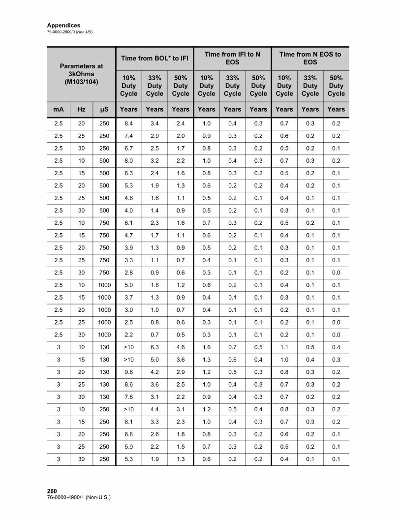
Appendices75-0000-2800/0 (Non-US)
2.5 20 250 8.4 3.4 2.4 1.0 0.4 0.3 0.7 0.3 0.2
2.5 25 250 7.4 2.9 2.0 0.9 0.3 0.2 0.6 0.2 0.2
2.5 30 250 6.7 2.5 1.7 0.8 0.3 0.2 0.5 0.2 0.1
2.5 10 500 8.0 3.2 2.2 1.0 0.4 0.3 0.7 0.3 0.2
2.5 15 500 6.3 2.4 1.6 0.8 0.3 0.2 0.5 0.2 0.1
2.5 20 500 5.3 1.9 1.3 0.6 0.2 0.2 0.4 0.2 0.1
2.5 25 500 4.6 1.6 1.1 0.5 0.2 0.1 0.4 0.1 0.1
2.5 30 500 4.0 1.4 0.9 0.5 0.2 0.1 0.3 0.1 0.1
2.5 10 750 6.1 2.3 1.6 0.7 0.3 0.2 0.5 0.2 0.1
2.5 15 750 4.7 1.7 1.1 0.6 0.2 0.1 0.4 0.1 0.1
2.5 20 750 3.9 1.3 0.9 0.5 0.2 0.1 0.3 0.1 0.1
2.5 25 750 3.3 1.1 0.7 0.4 0.1 0.1 0.3 0.1 0.1
2.5 30 750 2.8 0.9 0.6 0.3 0.1 0.1 0.2 0.1 0.0
2.5 10 1000 5.0 1.8 1.2 0.6 0.2 0.1 0.4 0.1 0.1
2.5 15 1000 3.7 1.3 0.9 0.4 0.1 0.1 0.3 0.1 0.1
2.5 20 1000 3.0 1.0 0.7 0.4 0.1 0.1 0.2 0.1 0.1
2.5 25 1000 2.5 0.8 0.6 0.3 0.1 0.1 0.2 0.1 0.0
2.5 30 1000 2.2 0.7 0.5 0.3 0.1 0.1 0.2 0.1 0.0
3 10 130 >10 6.3 4.6 1.6 0.7 0.5 1.1 0.5 0.4
3 15 130 >10 5.0 3.6 1.3 0.6 0.4 1.0 0.4 0.3
3 20 130 9.6 4.2 2.9 1.2 0.5 0.3 0.8 0.3 0.2
3 25 130 8.6 3.6 2.5 1.0 0.4 0.3 0.7 0.3 0.2
3 30 130 7.8 3.1 2.2 0.9 0.4 0.3 0.7 0.2 0.2
3 10 250 >10 4.4 3.1 1.2 0.5 0.4 0.8 0.3 0.2
3 15 250 8.1 3.3 2.3 1.0 0.4 0.3 0.7 0.3 0.2
3 20 250 6.8 2.6 1.8 0.8 0.3 0.2 0.6 0.2 0.1
3 25 250 5.9 2.2 1.5 0.7 0.3 0.2 0.5 0.2 0.1
3 30 250 5.3 1.9 1.3 0.6 0.2 0.2 0.4 0.1 0.1
Parameters at 3kOhms
(M103/104)
Time from BOL* to IFITime from IFI to N
EOSTime from N EOS to
EOS
10% Duty Cycle
33% Duty Cycle
50% Duty Cycle
10% Duty Cycle
33% Duty Cycle
50% Duty Cycle
10% Duty Cycle
33% Duty Cycle
50% Duty Cycle
mA Hz μS Years Years Years Years Years Years Years Years Years
26076-0000-4900/1 (Non-U.S.)

Appendices75-0000-2800/0 (Non-US)
3 10 500 6.6 2.5 1.7 0.8 0.3 0.2 0.5 0.2 0.1
3 15 500 5.0 1.8 1.2 0.6 0.2 0.1 0.4 0.1 0.1
3 20 500 4.0 1.4 0.9 0.5 0.2 0.1 0.3 0.1 0.1
3 25 500 3.4 1.2 0.8 0.4 0.1 0.1 0.3 0.1 0.1
3 30 500 3.0 1.0 0.7 0.3 0.1 0.1 0.2 0.1 0.1
3 10 750 4.9 1.7 1.2 0.6 0.2 0.1 0.4 0.1 0.1
3 15 750 3.6 1.2 0.8 0.4 0.1 0.1 0.3 0.1 0.1
3 20 750 2.8 0.9 0.6 0.3 0.1 0.1 0.2 0.1 0.0
3 25 750 2.4 0.8 0.5 0.3 0.1 0.1 0.2 0.1 0.0
3 30 750 2.0 0.7 0.4 0.2 0.1 0.1 0.2 0.1 0.0
3 10 1000 3.8 1.3 0.9 0.4 0.2 0.1 0.3 0.1 0.1
3 15 1000 2.8 0.9 0.6 0.3 0.1 0.1 0.2 0.1 0.0
3 20 1000 2.2 0.7 0.5 0.3 0.1 0.1 0.2 0.1 0.0
3 25 1000 1.8 0.6 0.4 0.2 0.1 0.0 0.1 0.0 0.0
3 30 1000 1.5 0.5 0.3 0.2 0.1 0.0 0.1 0.0 0.0
3.5 10 130 >10 4.7 3.4 1.3 0.6 0.4 0.9 0.4 0.3
3.5 15 130 9.0 3.8 2.6 1.1 0.4 0.3 0.8 0.3 0.2
3.5 20 130 7.7 3.1 2.1 0.9 0.4 0.3 0.6 0.2 0.2
3.5 25 130 6.8 2.6 1.8 0.8 0.3 0.2 0.6 0.2 0.1
3.5 30 130 6.1 2.3 1.6 0.7 0.3 0.2 0.5 0.2 0.1
3.5 10 250 8.0 3.2 2.2 1.0 0.4 0.3 0.7 0.3 0.2
3.5 15 250 6.4 2.4 1.7 0.8 0.3 0.2 0.5 0.2 0.1
3.5 20 250 5.3 1.9 1.3 0.6 0.2 0.2 0.4 0.2 0.1
3.5 25 250 4.6 1.6 1.1 0.5 0.2 0.1 0.4 0.1 0.1
3.5 30 250 4.0 1.4 0.9 0.5 0.2 0.1 0.3 0.1 0.1
3.5 10 500 4.7 1.7 1.1 0.6 0.2 0.1 0.4 0.1 0.1
3.5 15 500 3.6 1.2 0.8 0.4 0.1 0.1 0.3 0.1 0.1
3.5 20 500 3.0 1.0 0.7 0.3 0.1 0.1 0.2 0.1 0.1
Parameters at 3kOhms
(M103/104)
Time from BOL* to IFITime from IFI to N
EOSTime from N EOS to
EOS
10% Duty Cycle
33% Duty Cycle
50% Duty Cycle
10% Duty Cycle
33% Duty Cycle
50% Duty Cycle
10% Duty Cycle
33% Duty Cycle
50% Duty Cycle
mA Hz μS Years Years Years Years Years Years Years Years Years
26176-0000-4900/1 (Non-U.S.)

Appendices75-0000-2800/0 (Non-US)
3.5 25 500 2.5 0.8 0.5 0.3 0.1 0.1 0.2 0.1 0.0
3.5 30 500 2.1 0.7 0.5 0.2 0.1 0.1 0.2 0.1 0.0
3.5 10 750 3.2 1.1 0.7 0.4 0.1 0.1 0.3 0.1 0.1
3.5 15 750 2.4 0.8 0.5 0.3 0.1 0.1 0.2 0.1 0.0
3.5 20 750 2.0 0.6 0.4 0.2 0.1 0.0 0.2 0.1 0.0
3.5 25 750 1.7 0.5 0.4 0.2 0.1 0.0 0.1 0.0 0.0
3.5 30 750 1.4 0.5 0.3 0.2 0.1 0.0 0.1 0.0 0.0
3.5 10 1000 2.4 0.8 0.5 0.3 0.1 0.1 0.2 0.1 0.0
3.5 15 1000 1.9 0.6 0.4 0.2 0.1 0.0 0.2 0.0 0.0
3.5 20 1000 1.5 0.5 0.3 0.2 0.1 0.0 0.1 0.0 0.0
3.5 25 1000 1.3 0.4 0.3 0.1 0.0 0.0 0.1 0.0 0.0
3.5 30 1000 1.1 0.3 0.2 0.1 0.0 0.0 0.1 0.0 0.0
*BOL - “Beginning of Life”
Parameters at 3kOhms
(M103/104)
Time from BOL* to IFITime from IFI to N
EOSTime from N EOS to
EOS
10% Duty Cycle
33% Duty Cycle
50% Duty Cycle
10% Duty Cycle
33% Duty Cycle
50% Duty Cycle
10% Duty Cycle
33% Duty Cycle
50% Duty Cycle
mA Hz μS Years Years Years Years Years Years Years Years Years
26276-0000-4900/1 (Non-U.S.)

Appendices75-0000-2800/0 (Non-US)
15.2. Appendix B — Model 105 Battery Longevity and Programmed Setting Choices
Parameters at 3kOhms (M105)
Time from BOL* to IFITime from IFI to
N EOSTime from N EOS to
EOS
10% Duty Cycle
33% Duty Cycle
50% Duty Cycle
10% Duty Cycle
33% Duty Cycle
50% Duty Cycle
10% Duty Cycle
33% Duty Cycle
50% Duty Cycle
mA Hz μS Years Years Years Years Years Years Years Years Years
0.5 10 130 >10 >10 >10 2.5 1.6 1.3 1.9 1.2 0.9
0.5 15 130 >10 >10 >10 2.5 1.5 1.2 1.8 1.1 0.9
0.5 20 130 >10 >10 >10 2.4 1.4 1.1 1.7 1.0 0.8
0.5 25 130 >10 >10 >10 2.2 1.3 1.0 1.7 1.0 0.7
0.5 30 130 >10 >10 >10 2.2 1.2 0.9 1.6 0.9 0.7
0.5 10 250 >10 >10 >10 2.5 1.6 1.3 1.9 1.2 1.0
0.5 15 250 >10 >10 >10 2.4 1.4 1.1 1.8 1.1 0.8
0.5 20 250 >10 >10 >10 2.3 1.3 1.0 1.7 1.0 0.7
0.5 25 250 >10 >10 >10 2.2 1.2 0.9 1.6 0.9 0.7
0.5 30 250 >10 >10 >10 2.1 1.1 0.8 1.5 0.8 0.6
0.5 10 500 >10 >10 >10 2.4 1.4 1.1 1.7 1.0 0.8
0.5 15 500 >10 >10 >10 2.2 1.2 0.9 1.6 0.9 0.7
0.5 20 500 >10 >10 >10 2.0 1.1 0.8 1.5 0.8 0.6
0.5 25 500 >10 >10 9.0 1.9 0.9 0.7 1.4 0.7 0.5
0.5 30 500 >10 >10 8.6 1.8 0.9 0.6 1.3 0.7 0.5
0.5 10 750 >10 >10 >10 2.2 1.3 1.0 1.7 0.9 0.7
0.5 15 750 >10 >10 >10 2.0 1.1 0.8 1.5 0.8 0.6
0.5 20 750 >10 >10 8.9 1.9 0.9 0.7 1.4 0.7 0.5
0.5 25 750 >10 >10 7.7 1.7 0.8 0.6 1.3 0.6 0.4
0.5 30 750 >10 9.6 6.8 1.6 0.7 0.5 1.2 0.5 0.4
0.5 10 1000 >10 >10 >10 2.1 1.2 0.9 1.6 0.9 0.6
0.5 15 1000 >10 >10 8.9 1.9 0.9 0.7 1.4 0.7 0.5
0.5 20 1000 >10 >10 7.3 1.7 0.8 0.6 1.2 0.6 0.4
0.5 25 1000 >10 9.2 6.5 1.5 0.7 0.5 1.1 0.5 0.4
26376-0000-4900/1 (Non-U.S.)

Appendices75-0000-2800/0 (Non-US)
0.5 30 1000 >10 8.0 5.7 1.4 0.6 0.4 1.0 0.4 0.3
1 10 130 >10 >10 >10 2.4 1.4 1.1 1.7 0.9 0.7
1 15 130 >10 >10 >10 2.3 1.4 1.0 1.6 0.9 0.7
1 20 130 >10 >10 >10 2.3 1.3 1.0 1.6 0.9 0.7
1 25 130 >10 >10 >10 2.2 1.2 0.9 1.5 0.8 0.6
1 30 130 >10 >10 >10 2.1 1.1 0.8 1.5 0.8 0.6
1 10 250 >10 >10 >10 2.2 1.2 0.9 1.5 0.8 0.6
1 15 250 >10 >10 >10 2.1 1.1 0.8 1.5 0.8 0.6
1 20 250 >10 >10 >10 2.0 1.0 0.7 1.4 0.7 0.5
1 25 250 >10 >10 9.7 1.9 0.9 0.7 1.3 0.6 0.5
1 30 250 >10 >10 8.9 1.8 0.8 0.6 1.2 0.6 0.4
1 10 500 >10 >10 >10 2.0 1.0 0.7 1.3 0.6 0.5
1 15 500 >10 >10 9.6 1.8 0.8 0.6 1.2 0.5 0.4
1 20 500 >10 >10 7.8 1.6 0.7 0.5 1.1 0.5 0.3
1 25 500 >10 9.3 6.6 1.4 0.6 0.4 1.0 0.4 0.3
1 30 500 >10 8.4 5.9 1.3 0.6 0.4 0.9 0.4 0.3
1 10 750 >10 >10 9.7 1.7 0.8 0.6 1.2 0.5 0.4
1 15 750 >10 >10 7.4 1.5 0.7 0.5 1.0 0.4 0.3
1 20 750 >10 8.6 6.0 1.3 0.6 0.4 0.9 0.4 0.3
1 25 750 >10 7.3 5.1 1.2 0.5 0.3 0.8 0.3 0.2
1 30 750 >10 6.4 4.4 1.1 0.4 0.3 0.7 0.3 0.2
1 10 1000 >10 >10 8.0 1.5 0.7 0.5 1.0 0.4 0.3
1 15 1000 >10 8.8 6.2 1.3 0.5 0.4 0.9 0.4 0.2
1 20 1000 >10 7.1 4.9 1.1 0.5 0.3 0.8 0.3 0.2
1 25 1000 >10 6.0 4.1 1.0 0.4 0.3 0.7 0.3 0.2
1 30 1000 >10 5.1 3.5 0.9 0.3 0.2 0.6 0.2 0.2
1.5 10 130 >10 >10 >10 2.0 1.1 0.8 1.5 0.7 0.6
1.5 15 130 >10 >10 >10 1.9 1.0 0.7 1.4 0.7 0.5
Parameters at 3kOhms (M105)
Time from BOL* to IFITime from IFI to
N EOSTime from N EOS to
EOS
10% Duty Cycle
33% Duty Cycle
50% Duty Cycle
10% Duty Cycle
33% Duty Cycle
50% Duty Cycle
10% Duty Cycle
33% Duty Cycle
50% Duty Cycle
mA Hz μS Years Years Years Years Years Years Years Years Years
26476-0000-4900/1 (Non-U.S.)

Appendices75-0000-2800/0 (Non-US)
1.5 20 130 >10 >10 9.4 1.8 0.9 0.7 1.3 0.6 0.5
1.5 25 130 >10 >10 8.8 1.8 0.8 0.6 1.3 0.6 0.4
1.5 30 130 >10 >10 7.8 1.7 0.8 0.6 1.2 0.6 0.4
1.5 10 250 >10 >10 9.3 1.8 0.9 0.6 1.3 0.6 0.4
1.5 15 250 >10 >10 7.9 1.6 0.7 0.5 1.1 0.5 0.4
1.5 20 250 >10 >10 7.6 1.6 0.7 0.5 1.1 0.5 0.3
1.5 25 250 >10 9.1 6.5 1.4 0.6 0.4 1.0 0.4 0.3
1.5 30 250 >10 8.5 6.0 1.3 0.6 0.4 0.9 0.4 0.3
1.5 10 500 >10 9.4 6.6 1.4 0.6 0.4 1.0 0.4 0.3
1.5 15 500 >10 7.4 5.2 1.2 0.5 0.3 0.8 0.3 0.2
1.5 20 500 >10 6.5 4.5 1.1 0.4 0.3 0.7 0.3 0.2
1.5 25 500 >10 5.7 4.0 1.0 0.4 0.3 0.7 0.2 0.2
1.5 30 500 >10 5.1 3.5 0.9 0.3 0.2 0.6 0.2 0.1
1.5 10 750 >10 7.2 5.0 1.2 0.5 0.3 0.8 0.3 0.2
1.5 15 750 >10 5.5 3.8 1.0 0.4 0.2 0.7 0.2 0.2
1.5 20 750 >10 4.7 3.2 0.8 0.3 0.2 0.6 0.2 0.1
1.5 25 750 >10 4.0 2.7 0.7 0.3 0.2 0.5 0.2 0.1
1.5 30 750 10.0 3.6 2.4 0.7 0.2 0.2 0.4 0.2 0.1
1.5 10 1000 >10 5.7 4.0 1.0 0.4 0.3 0.7 0.2 0.2
1.5 15 1000 >10 4.3 2.9 0.8 0.3 0.2 0.5 0.2 0.1
1.5 20 1000 9.9 3.5 2.4 0.7 0.2 0.2 0.4 0.2 0.1
1.5 25 1000 8.7 3.1 2.1 0.6 0.2 0.1 0.4 0.1 0.1
1.5 30 1000 7.8 2.7 1.8 0.5 0.2 0.1 0.3 0.1 0.1
2 10 130 >10 >10 9.4 1.8 0.9 0.6 1.3 0.6 0.4
2 15 130 >10 >10 8.0 1.7 0.8 0.5 1.2 0.5 0.4
2 20 130 >10 9.8 7.0 1.5 0.7 0.5 1.1 0.5 0.3
2 25 130 >10 8.8 6.2 1.4 0.6 0.4 1.0 0.4 0.3
2 30 130 >10 8.1 5.7 1.3 0.6 0.4 0.9 0.4 0.3
Parameters at 3kOhms (M105)
Time from BOL* to IFITime from IFI to
N EOSTime from N EOS to
EOS
10% Duty Cycle
33% Duty Cycle
50% Duty Cycle
10% Duty Cycle
33% Duty Cycle
50% Duty Cycle
10% Duty Cycle
33% Duty Cycle
50% Duty Cycle
mA Hz μS Years Years Years Years Years Years Years Years Years
26576-0000-4900/1 (Non-U.S.)

Appendices75-0000-2800/0 (Non-US)
2 10 250 >10 9.7 6.9 1.5 0.7 0.5 1.0 0.4 0.3
2 15 250 >10 8.2 5.7 1.3 0.5 0.4 0.9 0.4 0.3
2 20 250 >10 6.8 4.7 1.1 0.5 0.3 0.8 0.3 0.2
2 25 250 >10 5.9 4.1 1.0 0.4 0.3 0.7 0.3 0.2
2 30 250 >10 5.2 3.6 0.9 0.4 0.2 0.6 0.2 0.2
2 10 500 >10 6.5 4.5 1.1 0.4 0.3 0.7 0.3 0.2
2 15 500 >10 5.0 3.4 0.9 0.3 0.2 0.6 0.2 0.1
2 20 500 >10 4.0 2.7 0.7 0.3 0.2 0.5 0.2 0.1
2 25 500 9.6 3.4 2.3 0.7 0.2 0.2 0.4 0.2 0.1
2 30 500 8.7 3.0 2.1 0.6 0.2 0.1 0.4 0.1 0.1
2 10 750 >10 4.8 3.3 0.9 0.3 0.2 0.6 0.2 0.1
2 15 750 >10 3.6 2.4 0.7 0.2 0.2 0.4 0.2 0.1
2 20 750 8.1 2.8 1.9 0.5 0.2 0.1 0.4 0.1 0.1
2 25 750 7.0 2.4 1.6 0.5 0.2 0.1 0.3 0.1 0.1
2 30 750 6.2 2.1 1.4 0.4 0.1 0.1 0.3 0.1 0.1
2 10 1000 >10 3.8 2.6 0.7 0.2 0.2 0.5 0.2 0.1
2 15 1000 8.0 2.8 1.9 0.5 0.2 0.1 0.4 0.1 0.1
2 20 1000 6.5 2.2 1.5 0.4 0.1 0.1 0.3 0.1 0.1
2 25 1000 5.5 1.8 1.2 0.4 0.1 0.1 0.2 0.1 0.1
2 30 1000 4.8 1.6 1.1 0.3 0.1 0.1 0.2 0.1 0.0
2.5 10 130 >10 >10 8.3 1.7 0.8 0.6 1.2 0.5 0.4
2.5 15 130 >10 9.6 6.8 1.5 0.6 0.5 1.0 0.4 0.3
2.5 20 130 >10 8.5 6.0 1.4 0.6 0.4 0.9 0.4 0.3
2.5 25 130 >10 7.4 5.2 1.2 0.5 0.4 0.9 0.3 0.2
2.5 30 130 >10 6.7 4.7 1.1 0.5 0.3 0.8 0.3 0.2
2.5 10 250 >10 8.3 5.9 1.3 0.6 0.4 0.9 0.4 0.3
2.5 15 250 >10 6.5 4.5 1.1 0.4 0.3 0.8 0.3 0.2
2.5 20 250 >10 5.5 3.8 1.0 0.4 0.3 0.7 0.2 0.2
Parameters at 3kOhms (M105)
Time from BOL* to IFITime from IFI to
N EOSTime from N EOS to
EOS
10% Duty Cycle
33% Duty Cycle
50% Duty Cycle
10% Duty Cycle
33% Duty Cycle
50% Duty Cycle
10% Duty Cycle
33% Duty Cycle
50% Duty Cycle
mA Hz μS Years Years Years Years Years Years Years Years Years
26676-0000-4900/1 (Non-U.S.)

Appendices75-0000-2800/0 (Non-US)
2.5 25 250 >10 4.6 3.2 0.8 0.3 0.2 0.6 0.2 0.1
2.5 30 250 >10 4.1 2.8 0.8 0.3 0.2 0.5 0.2 0.1
2.5 10 500 >10 5.4 3.7 0.9 0.4 0.2 0.6 0.2 0.2
2.5 15 500 >10 4.0 2.7 0.7 0.3 0.2 0.5 0.2 0.1
2.5 20 500 9.0 3.2 2.1 0.6 0.2 0.1 0.4 0.1 0.1
2.5 25 500 7.8 2.7 1.8 0.5 0.2 0.1 0.3 0.1 0.1
2.5 30 500 6.8 2.3 1.5 0.5 0.2 0.1 0.3 0.1 0.1
2.5 10 750 >10 3.9 2.7 0.7 0.3 0.2 0.5 0.2 0.1
2.5 15 750 8.2 2.9 1.9 0.5 0.2 0.1 0.4 0.1 0.1
2.5 20 750 6.6 2.2 1.5 0.4 0.1 0.1 0.3 0.1 0.1
2.5 25 750 5.5 1.8 1.2 0.4 0.1 0.1 0.2 0.1 0.1
2.5 30 750 4.9 1.6 1.1 0.3 0.1 0.1 0.2 0.1 0.0
2.5 10 1000 8.8 3.1 2.1 0.6 0.2 0.1 0.4 0.1 0.1
2.5 15 1000 6.5 2.2 1.5 0.4 0.1 0.1 0.3 0.1 0.1
2.5 20 1000 5.2 1.7 1.1 0.3 0.1 0.1 0.2 0.1 0.0
2.5 25 1000 4.3 1.4 0.9 0.3 0.1 0.1 0.2 0.1 0.0
2.5 30 1000 3.7 1.2 0.8 0.2 0.1 0.1 0.2 0.1 0.0
3 10 130 >10 >10 7.3 1.5 0.7 0.5 1.1 0.5 0.3
3 15 130 >10 8.5 6.0 1.3 0.6 0.4 0.9 0.4 0.3
3 20 130 >10 7.4 5.1 1.2 0.5 0.3 0.8 0.3 0.2
3 25 130 >10 6.2 4.3 1.1 0.4 0.3 0.7 0.3 0.2
3 30 130 >10 5.5 3.8 1.0 0.4 0.3 0.7 0.2 0.2
3 10 250 >10 6.9 4.8 1.2 0.5 0.3 0.8 0.3 0.2
3 15 250 >10 5.3 3.7 0.9 0.4 0.2 0.6 0.2 0.2
3 20 250 >10 4.4 3.0 0.8 0.3 0.2 0.5 0.2 0.1
3 25 250 >10 3.7 2.5 0.7 0.2 0.2 0.5 0.2 0.1
3 30 250 9.2 3.2 2.2 0.6 0.2 0.1 0.4 0.1 0.1
3 10 500 >10 4.1 2.8 0.8 0.3 0.2 0.5 0.2 0.1
Parameters at 3kOhms (M105)
Time from BOL* to IFITime from IFI to
N EOSTime from N EOS to
EOS
10% Duty Cycle
33% Duty Cycle
50% Duty Cycle
10% Duty Cycle
33% Duty Cycle
50% Duty Cycle
10% Duty Cycle
33% Duty Cycle
50% Duty Cycle
mA Hz μS Years Years Years Years Years Years Years Years Years
26776-0000-4900/1 (Non-U.S.)

Appendices75-0000-2800/0 (Non-US)
3 15 500 8.7 3.1 2.1 0.6 0.2 0.1 0.4 0.1 0.1
3 20 500 7.1 2.4 1.6 0.5 0.2 0.1 0.3 0.1 0.1
3 25 500 6.1 2.0 1.4 0.4 0.1 0.1 0.3 0.1 0.1
3 30 500 5.3 1.7 1.2 0.3 0.1 0.1 0.2 0.1 0.0
3 10 750 8.4 2.9 2.0 0.6 0.2 0.1 0.4 0.1 0.1
3 15 750 6.3 2.1 1.4 0.4 0.1 0.1 0.3 0.1 0.1
3 20 750 5.1 1.7 1.1 0.3 0.1 0.1 0.2 0.1 0.0
3 25 750 4.2 1.4 0.9 0.3 0.1 0.1 0.2 0.1 0.0
3 30 750 3.6 1.2 0.8 0.2 0.1 0.1 0.2 0.0 0.0
3 10 1000 6.6 2.2 1.5 0.4 0.1 0.1 0.3 0.1 0.1
3 15 1000 4.9 1.6 1.1 0.3 0.1 0.1 0.2 0.1 0.0
3 20 1000 3.9 1.3 0.8 0.3 0.1 0.1 0.2 0.1 0.0
3 25 1000 3.2 1.0 0.7 0.2 0.1 0.0 0.1 0.0 0.0
3 30 1000 2.7 0.9 0.6 0.2 0.1 0.0 0.1 0.0 0.0
3.5 10 130 >10 6.7 4.7 1.2 0.5 0.3 0.9 0.4 0.2
3.5 15 130 >10 6.0 4.1 1.1 0.4 0.3 0.8 0.3 0.2
3.5 20 130 >10 5.0 3.4 0.9 0.4 0.2 0.7 0.2 0.2
3.5 25 130 >10 4.6 3.1 0.8 0.3 0.2 0.6 0.2 0.1
3.5 30 130 >10 4.1 2.8 0.8 0.3 0.2 0.5 0.2 0.1
3.5 10 250 >10 4.6 3.1 0.9 0.3 0.2 0.6 0.2 0.1
3.5 15 250 >10 3.6 2.5 0.7 0.2 0.2 0.5 0.2 0.1
3.5 20 250 8.7 3.0 2.1 0.6 0.2 0.1 0.4 0.1 0.1
3.5 25 250 7.5 2.6 1.7 0.5 0.2 0.1 0.3 0.1 0.1
3.5 30 250 6.7 2.3 1.5 0.5 0.2 0.1 0.3 0.1 0.1
3.5 10 500 7.2 2.4 1.6 0.5 0.2 0.1 0.4 0.1 0.1
3.5 15 500 5.9 2.0 1.3 0.4 0.1 0.1 0.3 0.1 0.1
3.5 20 500 5.0 1.6 1.1 0.3 0.1 0.1 0.2 0.1 0.0
3.5 25 500 4.3 1.4 0.9 0.3 0.1 0.1 0.2 0.1 0.0
Parameters at 3kOhms (M105)
Time from BOL* to IFITime from IFI to
N EOSTime from N EOS to
EOS
10% Duty Cycle
33% Duty Cycle
50% Duty Cycle
10% Duty Cycle
33% Duty Cycle
50% Duty Cycle
10% Duty Cycle
33% Duty Cycle
50% Duty Cycle
mA Hz μS Years Years Years Years Years Years Years Years Years
26876-0000-4900/1 (Non-U.S.)

Appendices75-0000-2800/0 (Non-US)
3.5 30 500 3.7 1.2 0.8 0.2 0.1 0.1 0.2 0.1 0.0
3.5 10 750 5.2 1.7 1.1 0.4 0.1 0.1 0.3 0.1 0.1
3.5 15 750 4.1 1.3 0.9 0.3 0.1 0.1 0.2 0.1 0.0
3.5 20 750 3.4 1.1 0.7 0.2 0.1 0.0 0.2 0.0 0.0
3.5 25 750 3.0 0.9 0.6 0.2 0.1 0.0 0.1 0.0 0.0
3.5 30 750 2.6 0.8 0.5 0.2 0.1 0.0 0.1 0.0 0.0
3.5 10 1000 4.4 1.4 1.0 0.3 0.1 0.1 0.2 0.1 0.0
3.5 15 1000 3.4 1.1 0.7 0.2 0.1 0.0 0.2 0.0 0.0
3.5 20 1000 2.8 0.9 0.6 0.2 0.1 0.0 0.1 0.0 0.0
3.5 25 1000 2.3 0.7 0.5 0.2 0.0 0.0 0.1 0.0 0.0
3.5 30 1000 2.0 0.6 0.4 0.1 0.0 0.0 0.1 0.0 0.0
*BOL - Beginning of Life
Parameters at 3kOhms (M105)
Time from BOL* to IFITime from IFI to
N EOSTime from N EOS to
EOS
10% Duty Cycle
33% Duty Cycle
50% Duty Cycle
10% Duty Cycle
33% Duty Cycle
50% Duty Cycle
10% Duty Cycle
33% Duty Cycle
50% Duty Cycle
mA Hz μS Years Years Years Years Years Years Years Years Years
26976-0000-4900/1 (Non-U.S.)

Appendices75-0000-2800/0 (Non-US)
Note: For more information see Battery longevity and programmed setting choices in the 106 Technical Information chapter.
15.3. Appendix C — Model 106 Battery Longevity and Programmed Setting Choices (With Seizure Detection Disabled)
Parameters at 3kOhms (M106)
Time from BOL* to IFITime from IFI to
N EOSTime from N EOS to
EOS
10% Duty Cycle
33% Duty Cycle
50% Duty Cycle
10% Duty Cycle
33% Duty Cycle
50% Duty Cycle
10% Duty Cycle
33% Duty Cycle
50% Duty Cycle
mA Hz µS Years Years Years Years Years Years Years Years Years
0.5 10 130 >10 >10 >10 3.0 2.5 2.2 2.2 1.8 1.6
0.5 10 250 >10 >10 >10 2.9 2.3 2.0 2.2 1.7 1.5
0.5 10 500 >10 >10 >10 2.7 1.9 1.6 2.0 1.4 1.2
0.5 10 750 >10 >10 >10 2.6 1.7 1.3 1.9 1.2 1.0
0.5 10 1000 >10 >10 >10 2.4 1.5 1.1 1.8 1.1 0.8
0.5 15 130 >10 >10 >10 2.9 2.2 1.9 2.1 1.6 1.4
0.5 15 250 >10 >10 >10 2.8 2.0 1.7 2.1 1.5 1.2
0.5 15 500 >10 >10 >10 2.5 1.6 1.3 1.9 1.2 0.9
0.5 15 750 >10 >10 >10 2.3 1.4 1.0 1.7 1.0 0.8
0.5 15 1000 >10 >10 >10 2.1 1.2 0.9 1.6 0.9 0.6
0.5 20 130 >10 >10 >10 2.8 2.0 1.7 2.1 1.5 1.2
0.5 20 250 >10 >10 >10 2.7 1.8 1.5 2.0 1.3 1.1
0.5 20 500 >10 >10 >10 2.4 1.4 1.1 1.7 1.0 0.8
0.5 20 750 >10 >10 >10 2.1 1.1 0.9 1.6 0.8 0.6
0.5 20 1000 >10 >10 9.3 1.9 1.0 0.7 1.4 0.7 0.5
0.5 25 130 >10 >10 >10 2.7 1.8 1.5 2.0 1.4 1.1
0.5 25 250 >10 >10 >10 2.5 1.6 1.3 1.9 1.2 1.0
0.5 25 500 >10 >10 >10 2.2 1.2 0.9 1.6 0.9 0.7
0.5 25 750 >10 >10 9.6 1.9 1.0 0.7 1.4 0.7 0.5
0.5 25 1000 >10 >10 7.8 1.7 0.8 0.6 1.3 0.6 0.4
0.5 30 130 >10 >10 >10 2.6 1.7 1.3 1.9 1.3 1.0
0.5 30 250 >10 >10 >10 2.4 1.5 1.2 1.8 1.1 0.9
27076-0000-4900/1 (Non-U.S.)

Appendices75-0000-2800/0 (Non-US)
0.5 30 500 >10 >10 >10 2.1 1.1 0.8 1.5 0.8 0.6
0.5 30 750 >10 >10 8.3 1.8 0.9 0.6 1.3 0.6 0.5
0.5 30 1000 >10 9.5 6.7 1.6 0.7 0.5 1.2 0.5 0.4
1 10 130 >10 >10 >10 2.7 1.8 1.5 1.9 1.2 1.0
1 10 250 >10 >10 >10 2.5 1.6 1.2 1.7 1.0 0.8
1 10 500 >10 >10 >10 2.2 1.2 0.9 1.5 0.8 0.6
1 10 750 >10 >10 >10 2.0 1.0 0.7 1.3 0.6 0.4
1 10 1000 >10 >10 9.7 1.8 0.8 0.6 1.1 0.5 0.4
1 15 130 >10 >10 >10 2.6 1.7 1.4 1.8 1.2 0.9
1 15 250 >10 >10 >10 2.4 1.4 1.1 1.6 0.9 0.7
1 15 500 >10 >10 >10 2.0 1.1 0.8 1.3 0.7 0.5
1 15 750 >10 >10 8.7 1.7 0.8 0.6 1.1 0.5 0.4
1 15 1000 >10 9.8 7.0 1.5 0.7 0.5 1.0 0.4 0.3
1 20 130 >10 >10 >10 2.5 1.6 1.3 1.8 1.1 0.9
1 20 250 >10 >10 >10 2.3 1.3 1.0 1.6 0.8 0.6
1 20 500 >10 >10 9.3 1.8 0.9 0.7 1.2 0.6 0.4
1 20 750 >10 9.7 6.9 1.5 0.7 0.5 1.0 0.4 0.3
1 20 1000 >10 7.8 5.5 1.3 0.5 0.4 0.8 0.3 0.2
1 25 130 >10 >10 >10 2.4 1.5 1.2 1.7 1.0 0.8
1 25 250 >10 >10 >10 2.1 1.2 0.9 1.5 0.8 0.6
1 25 500 >10 >10 7.8 1.7 0.8 0.6 1.1 0.5 0.3
1 25 750 >10 8.2 5.7 1.4 0.6 0.4 0.9 0.4 0.2
1 25 1000 >10 6.5 4.5 1.2 0.5 0.3 0.7 0.3 0.2
1 30 130 >10 >10 >10 2.4 1.4 1.1 1.7 1.0 0.7
1 30 250 >10 >10 >10 2.0 1.0 0.8 1.4 0.7 0.5
1 30 500 >10 9.5 6.7 1.5 0.7 0.5 1.0 0.4 0.3
1 30 750 >10 7.0 4.9 1.2 0.5 0.3 0.8 0.3 0.2
1 30 1000 >10 5.6 3.8 1.0 0.4 0.3 0.7 0.2 0.2
Parameters at 3kOhms (M106)
Time from BOL* to IFITime from IFI to
N EOSTime from N EOS to
EOS
10% Duty Cycle
33% Duty Cycle
50% Duty Cycle
10% Duty Cycle
33% Duty Cycle
50% Duty Cycle
10% Duty Cycle
33% Duty Cycle
50% Duty Cycle
mA Hz µS Years Years Years Years Years Years Years Years Years
27176-0000-4900/1 (Non-U.S.)

Appendices75-0000-2800/0 (Non-US)
1.5 10 130 >10 >10 >10 2.3 1.3 1.0 1.6 0.9 0.7
1.5 10 250 >10 >10 >10 2.0 1.0 0.8 1.4 0.7 0.5
1.5 10 500 >10 >10 7.9 1.6 0.7 0.5 1.1 0.5 0.3
1.5 10 750 >10 8.1 5.7 1.2 0.5 0.4 0.8 0.3 0.2
1.5 10 1000 >10 6.4 4.4 1.0 0.4 0.3 0.7 0.3 0.2
1.5 15 130 >10 >10 >10 2.2 1.2 0.9 1.5 0.8 0.6
1.5 15 250 >10 >10 9.7 1.8 0.9 0.6 1.3 0.6 0.4
1.5 15 500 >10 8.5 6.0 1.3 0.5 0.4 0.9 0.4 0.3
1.5 15 750 >10 6.1 4.2 1.0 0.4 0.3 0.7 0.3 0.2
1.5 15 1000 >10 4.7 3.2 0.8 0.3 0.2 0.6 0.2 0.1
1.5 20 130 >10 >10 >10 2.0 1.1 0.8 1.5 0.7 0.6
1.5 20 250 >10 >10 8.5 1.7 0.8 0.5 1.1 0.5 0.4
1.5 20 500 >10 7.2 5.0 1.2 0.5 0.3 0.8 0.3 0.2
1.5 20 750 >10 5.0 3.4 0.9 0.3 0.2 0.6 0.2 0.1
1.5 20 1000 >10 3.8 2.6 0.7 0.2 0.2 0.5 0.2 0.1
1.5 25 130 >10 >10 >10 1.9 1.0 0.7 1.4 0.7 0.5
1.5 25 250 >10 >10 7.5 1.5 0.7 0.5 1.1 0.5 0.3
1.5 25 500 >10 6.3 4.4 1.0 0.4 0.3 0.7 0.3 0.2
1.5 25 750 >10 4.3 2.9 0.8 0.3 0.2 0.5 0.2 0.1
1.5 25 1000 9.2 3.3 2.2 0.6 0.2 0.1 0.4 0.1 0.1
1.5 30 130 >10 >10 9.8 1.8 0.9 0.7 1.3 0.6 0.4
1.5 30 250 >10 9.5 6.8 1.4 0.6 0.4 1.0 0.4 0.3
1.5 30 500 >10 5.5 3.8 0.9 0.4 0.2 0.6 0.2 0.2
1.5 30 750 >10 3.8 2.6 0.7 0.2 0.2 0.5 0.2 0.1
1.5 30 1000 8.2 2.8 1.9 0.5 0.2 0.1 0.4 0.1 0.1
2 10 130 >10 >10 >10 2.0 1.0 0.8 1.4 0.7 0.5
2 10 250 >10 >10 8.2 1.6 0.7 0.5 1.1 0.5 0.3
2 10 500 >10 7.2 5.0 1.2 0.5 0.3 0.8 0.3 0.2
Parameters at 3kOhms (M106)
Time from BOL* to IFITime from IFI to
N EOSTime from N EOS to
EOS
10% Duty Cycle
33% Duty Cycle
50% Duty Cycle
10% Duty Cycle
33% Duty Cycle
50% Duty Cycle
10% Duty Cycle
33% Duty Cycle
50% Duty Cycle
mA Hz µS Years Years Years Years Years Years Years Years Years
27276-0000-4900/1 (Non-U.S.)

Appendices75-0000-2800/0 (Non-US)
2 10 750 >10 5.2 3.6 0.9 0.3 0.2 0.6 0.2 0.1
2 10 1000 >10 4.0 2.8 0.7 0.3 0.2 0.5 0.2 0.1
2 15 130 >10 >10 9.5 1.8 0.9 0.6 1.3 0.6 0.4
2 15 250 >10 8.9 6.3 1.4 0.6 0.4 0.9 0.4 0.3
2 15 500 >10 5.3 3.7 0.9 0.3 0.2 0.6 0.2 0.2
2 15 750 >10 3.8 2.6 0.7 0.2 0.2 0.5 0.2 0.1
2 15 1000 8.3 2.9 2.0 0.5 0.2 0.1 0.4 0.1 0.1
2 20 130 >10 >10 8.1 1.6 0.8 0.5 1.1 0.5 0.4
2 20 250 >10 7.3 5.1 1.2 0.5 0.3 0.8 0.3 0.2
2 20 500 >10 4.2 2.9 0.8 0.3 0.2 0.5 0.2 0.1
2 20 750 8.4 2.9 2.0 0.6 0.2 0.1 0.4 0.1 0.1
2 20 1000 6.6 2.2 1.5 0.4 0.1 0.1 0.3 0.1 0.1
2 25 130 >10 >10 7.2 1.5 0.7 0.5 1.1 0.5 0.3
2 25 250 >10 6.4 4.4 1.1 0.4 0.3 0.7 0.3 0.2
2 25 500 >10 3.6 2.4 0.7 0.2 0.2 0.5 0.2 0.1
2 25 750 7.2 2.5 1.7 0.5 0.2 0.1 0.3 0.1 0.1
2 25 1000 5.6 1.9 1.2 0.4 0.1 0.1 0.2 0.1 0.1
2 30 130 >10 9.0 6.4 1.4 0.6 0.4 1.0 0.4 0.3
2 30 250 >10 5.6 3.9 1.0 0.4 0.3 0.7 0.2 0.2
2 30 500 8.9 3.1 2.1 0.6 0.2 0.1 0.4 0.1 0.1
2 30 750 6.4 2.1 1.4 0.4 0.1 0.1 0.3 0.1 0.1
2 30 1000 4.9 1.6 1.1 0.3 0.1 0.1 0.2 0.1 0.0
2.5 10 130 >10 >10 9.9 1.8 0.9 0.7 1.3 0.6 0.4
2.5 10 250 >10 9.3 6.6 1.4 0.6 0.4 1.0 0.4 0.3
2.5 10 500 >10 5.8 4.0 1.0 0.4 0.3 0.6 0.2 0.2
2.5 10 750 >10 4.1 2.8 0.7 0.3 0.2 0.5 0.2 0.1
2.5 10 1000 9.1 3.2 2.2 0.6 0.2 0.1 0.4 0.1 0.1
2.5 15 130 >10 >10 8.0 1.6 0.7 0.5 1.1 0.5 0.3
Parameters at 3kOhms (M106)
Time from BOL* to IFITime from IFI to
N EOSTime from N EOS to
EOS
10% Duty Cycle
33% Duty Cycle
50% Duty Cycle
10% Duty Cycle
33% Duty Cycle
50% Duty Cycle
10% Duty Cycle
33% Duty Cycle
50% Duty Cycle
mA Hz µS Years Years Years Years Years Years Years Years Years
27376-0000-4900/1 (Non-U.S.)

Appendices75-0000-2800/0 (Non-US)
2.5 15 250 >10 7.2 5.0 1.2 0.5 0.3 0.8 0.3 0.2
2.5 15 500 >10 4.2 2.9 0.8 0.3 0.2 0.5 0.2 0.1
2.5 15 750 8.5 2.9 2.0 0.5 0.2 0.1 0.4 0.1 0.1
2.5 15 1000 6.7 2.3 1.5 0.4 0.1 0.1 0.3 0.1 0.1
2.5 20 130 >10 9.3 6.6 1.4 0.6 0.4 1.0 0.4 0.3
2.5 20 250 >10 5.8 4.0 1.0 0.4 0.3 0.7 0.3 0.2
2.5 20 500 9.3 3.3 2.2 0.6 0.2 0.1 0.4 0.1 0.1
2.5 20 750 6.8 2.3 1.5 0.4 0.1 0.1 0.3 0.1 0.1
2.5 20 1000 5.3 1.7 1.2 0.3 0.1 0.1 0.2 0.1 0.0
2.5 25 130 >10 8.1 5.7 1.3 0.5 0.4 0.9 0.4 0.3
2.5 25 250 >10 4.9 3.4 0.9 0.3 0.2 0.6 0.2 0.1
2.5 25 500 7.9 2.7 1.8 0.5 0.2 0.1 0.4 0.1 0.1
2.5 25 750 5.7 1.9 1.3 0.4 0.1 0.1 0.3 0.1 0.1
2.5 25 1000 4.4 1.4 1.0 0.3 0.1 0.1 0.2 0.1 0.0
2.5 30 130 >10 7.2 5.1 1.2 0.5 0.3 0.8 0.3 0.2
2.5 30 250 >10 4.3 2.9 0.8 0.3 0.2 0.5 0.2 0.1
2.5 30 500 7.0 2.4 1.6 0.5 0.2 0.1 0.3 0.1 0.1
2.5 30 750 4.9 1.6 1.1 0.3 0.1 0.1 0.2 0.1 0.0
2.5 30 1000 3.8 1.2 0.8 0.2 0.1 0.1 0.2 0.1 0.0
3 10 130 >10 >10 8.4 1.7 0.8 0.6 1.1 0.5 0.4
3 10 250 >10 7.5 5.3 1.2 0.5 0.3 0.8 0.3 0.2
3 10 500 >10 4.4 3.0 0.8 0.3 0.2 0.5 0.2 0.1
3 10 750 8.6 3.0 2.0 0.6 0.2 0.1 0.4 0.1 0.1
3 10 1000 6.8 2.3 1.5 0.4 0.1 0.1 0.3 0.1 0.1
3 15 130 >10 9.3 6.6 1.4 0.6 0.4 1.0 0.4 0.3
3 15 250 >10 5.7 3.9 1.0 0.4 0.3 0.7 0.2 0.2
3 15 500 9.0 3.2 2.1 0.6 0.2 0.1 0.4 0.1 0.1
3 15 750 6.4 2.2 1.5 0.4 0.1 0.1 0.3 0.1 0.1
Parameters at 3kOhms (M106)
Time from BOL* to IFITime from IFI to
N EOSTime from N EOS to
EOS
10% Duty Cycle
33% Duty Cycle
50% Duty Cycle
10% Duty Cycle
33% Duty Cycle
50% Duty Cycle
10% Duty Cycle
33% Duty Cycle
50% Duty Cycle
mA Hz µS Years Years Years Years Years Years Years Years Years
27476-0000-4900/1 (Non-U.S.)

Appendices75-0000-2800/0 (Non-US)
3 15 1000 5.0 1.6 1.1 0.3 0.1 0.1 0.2 0.1 0.0
3 20 130 >10 7.7 5.4 1.2 0.5 0.4 0.8 0.3 0.2
3 20 250 >10 4.6 3.1 0.8 0.3 0.2 0.5 0.2 0.1
3 20 500 7.3 2.5 1.7 0.5 0.2 0.1 0.3 0.1 0.1
3 20 750 5.1 1.7 1.1 0.3 0.1 0.1 0.2 0.1 0.0
3 20 1000 3.9 1.3 0.8 0.3 0.1 0.1 0.2 0.1 0.0
3 25 130 >10 6.6 4.6 1.1 0.4 0.3 0.8 0.3 0.2
3 25 250 >10 3.9 2.6 0.7 0.2 0.2 0.5 0.2 0.1
3 25 500 6.1 2.1 1.4 0.4 0.1 0.1 0.3 0.1 0.1
3 25 750 4.3 1.4 0.9 0.3 0.1 0.1 0.2 0.1 0.0
3 25 1000 3.3 1.0 0.7 0.2 0.1 0.0 0.1 0.0 0.0
3 30 130 >10 5.8 4.0 1.0 0.4 0.3 0.7 0.3 0.2
3 30 250 9.3 3.3 2.2 0.6 0.2 0.1 0.4 0.1 0.1
3 30 500 5.3 1.7 1.2 0.3 0.1 0.1 0.2 0.1 0.0
3 30 750 3.7 1.2 0.8 0.2 0.1 0.0 0.2 0.0 0.0
3 30 1000 2.8 0.9 0.6 0.2 0.1 0.0 0.1 0.0 0.0
3.5 10 130 >10 7.2 5.1 1.3 0.5 0.4 0.9 0.4 0.3
3.5 10 250 >10 4.7 3.2 0.9 0.3 0.2 0.6 0.2 0.2
3.5 10 500 7.3 2.5 1.7 0.5 0.2 0.1 0.4 0.1 0.1
3.5 10 750 5.3 1.7 1.2 0.4 0.1 0.1 0.2 0.1 0.1
3.5 10 1000 4.5 1.4 1.0 0.3 0.1 0.1 0.2 0.1 0.0
3.5 15 130 >10 6.1 4.2 1.1 0.4 0.3 0.8 0.3 0.2
3.5 15 250 >10 3.7 2.5 0.7 0.3 0.2 0.5 0.2 0.1
3.5 15 500 5.9 2.0 1.3 0.4 0.1 0.1 0.3 0.1 0.1
3.5 15 750 4.2 1.4 0.9 0.3 0.1 0.1 0.2 0.1 0.0
3.5 15 1000 3.4 1.1 0.7 0.2 0.1 0.0 0.2 0.0 0.0
3.5 20 130 >10 5.2 3.6 1.0 0.4 0.2 0.7 0.3 0.2
3.5 20 250 8.9 3.1 2.1 0.6 0.2 0.1 0.4 0.1 0.1
Parameters at 3kOhms (M106)
Time from BOL* to IFITime from IFI to
N EOSTime from N EOS to
EOS
10% Duty Cycle
33% Duty Cycle
50% Duty Cycle
10% Duty Cycle
33% Duty Cycle
50% Duty Cycle
10% Duty Cycle
33% Duty Cycle
50% Duty Cycle
mA Hz µS Years Years Years Years Years Years Years Years Years
27576-0000-4900/1 (Non-U.S.)

Appendices75-0000-2800/0 (Non-US)
3.5 20 500 5.0 1.6 1.1 0.3 0.1 0.1 0.2 0.1 0.0
3.5 20 750 3.5 1.1 0.7 0.2 0.1 0.0 0.2 0.0 0.0
3.5 20 1000 2.8 0.9 0.6 0.2 0.1 0.0 0.1 0.0 0.0
3.5 25 130 >10 4.6 3.1 0.9 0.3 0.2 0.6 0.2 0.1
3.5 25 250 7.7 2.7 1.8 0.5 0.2 0.1 0.3 0.1 0.1
3.5 25 500 4.3 1.4 0.9 0.3 0.1 0.1 0.2 0.1 0.0
3.5 25 750 2.9 0.9 0.6 0.2 0.1 0.0 0.1 0.0 0.0
3.5 25 1000 2.4 0.7 0.5 0.2 0.0 0.0 0.1 0.0 0.0
3.5 30 130 >10 4.1 2.8 0.8 0.3 0.2 0.5 0.2 0.1
3.5 30 250 6.8 2.3 1.6 0.5 0.2 0.1 0.3 0.1 0.1
3.5 30 500 3.7 1.2 0.8 0.2 0.1 0.1 0.2 0.1 0.0
3.5 30 750 2.6 0.8 0.5 0.2 0.1 0.0 0.1 0.0 0.0
3.5 30 1000 2.0 0.6 0.4 0.1 0.0 0.0 0.1 0.0 0.0
*BOL - Beginning of Life
Parameters at 3kOhms (M106)
Time from BOL* to IFITime from IFI to
N EOSTime from N EOS to
EOS
10% Duty Cycle
33% Duty Cycle
50% Duty Cycle
10% Duty Cycle
33% Duty Cycle
50% Duty Cycle
10% Duty Cycle
33% Duty Cycle
50% Duty Cycle
mA Hz µS Years Years Years Years Years Years Years Years Years
27676-0000-4900/1 (Non-U.S.)

Glossary
VNS Therapy® System
27776-0000-4900/1 (Non-U.S.)

Glossary75-0000-2900/1 (Non-US)
16. GLOSSARY ________________________________________
ACLS
Advanced Cardiac Life Support
AE (adverse event)
Any symptom, sign, illness, or experience that develops or worsens in severity and/or frequency during the course of a study or procedure (i.e., any changes from baseline)
AED
Antiepileptic drug(s)
ARR
Antidepressant Resistance Rating
AutoStim Mode activation
Mode of operation specific to the Model 106 AspireSR. The device listens for heart beats during Normal Mode Off-time. When an increase in heart rate is detected (indicative of some seizure types) a train of stimulation is triggered similar to that of a Magnet Mode activation.
baseline periods (depression)
D-02 acute phase — Two pre-implantation visits (Visits B1 and B2) for both groups
D-02 long-term phase — For the evaluation of efficacy, the period just before initiation of VNS Therapy; during the long-term phase, the baseline period of subjects who had been assigned to the acute treatment group during the acute phase differed from that of the subjects who had been assigned to the acute sham-control group; because this baseline period is just before treatment initiation for both groups, it is more comparable for analysis purposes
treatment group — During the long-term phase, the baseline for the subjects who had been assigned to the acute treatment group during the acute phase was the pre-implantation baseline (B1 & B2)
delayed treatment group (acute sham-control group) — During the long-term phase, the baseline for the subjects who had been assigned to the acute sham-control group during the acute phase was the final two acute study visits, V8 and V9 (acute study exit)
D-04 — The visit occurring after obtaining informed consent
27876-0000-4900/1 (Non-U.S.)
Glossary75-0000-2900/1 (Non-US)
BOL
Beginning of life
BPM
Beats per minute
CF card
Compact Flash card
Note: The CGI was developed by NIMH to provide a standardized assessment with clinically relevant anchors; it is one of the most widely used brief assessment tools in psychiatry.
CGI (Clinical Global Impressions) (depression)
Two 7-point scales completed by the clinical rater to assess the subject’s condition regarding the severity of illness (CGI-S) and global improvement (CGI-I); the severity scale ranges from 1 – “normal, not at all ill” to 7 – “among the most extremely ill patients;” the improvement scale ranges from 1 – “very much improved” to 7 – “very much worse”
chronic or recurrent depression
A current major depressive episode that is of at least two years in duration or a current major depressive episode in a patient with a history of multiple prior episodes of depression
Note: Physician expert consultants to the sponsor developed this designation.
clinical benefit (depression)
Degree of improvement in depression, as measured by the HRSD24
extraordinary clinical benefit, at least a 75% reduction from baseline
highly meaningful clinical benefit, at least a 50% but less than a 75% reduction from baseline
meaningful clinical benefit, at least a 25% but less than a 50% reduction from baseline
minimal or no clinical benefit, at least no change or less than a 25% reduction from baseline
worsened, increase in HRSD24 compared with baseline
complete response (complete responder or remitter) (depression)
Subjects who scored less than a pre-defined score were considered to have achieved a complete response; scores representing complete response were an HRSD24 raw score
of 9 or less, a MADRS raw score of 10 or less, or an IDS-SR raw score of 14 or less; this corresponds to the concept of remission, where the illness, in this case depression, has few to no residual symptoms present
27976-0000-4900/1 (Non-U.S.)

Glossary75-0000-2900/1 (Non-US)
Cyberonics magnets
Cyberonics-provided magnets included in VNS Patient Essentials kits
D-01, D-02, D-04 clinical studies (depression)
Clinical trials conducted in patients with chronic or recurrent treatment-resistant depression. The D-01 study was a long-term, open-label, uncontrolled trial of adjunctive VNS Therapy. The D-02 study included acute and long-term phases. The acute phase was a double-blind, randomized, sham-controlled trial of adjunctive VNS Therapy; the long-term phase was an open-label, uncontrolled trial of adjunctive VNS Therapy. The D-04 study was a long-term, prospective, observational study of patients with chronic or recurrent treatment-resistant depression who were being treated with standard antidepressant treatments, but not VNS Therapy.
duty cycle
Percentage of time during which stimulation occurs; stimulation time (programmed ON time plus 2 seconds of ramp-up time and 2 seconds of ramp-down time) divided by the sum of signal ON and OFF times
EAS
Electronic article surveillance
ECT (electroconvulsive therapy)
A treatment for depression and other indications using electrodes on the surface of the head to direct electrical current into the brain to induce a generalized seizure in a patient
electrode
Mechanical and electrical interface of the VNS Therapy System to the vagus nerve; part of the lead
Electrostatic discharge (ESD)
Sudden and momentary electric current that flows between two objects
EMI
Electromagnetic interference
EOS
End of service
28076-0000-4900/1 (Non-U.S.)

Glossary75-0000-2900/1 (Non-US)
ERI
Elective replacement indicator. Synonymous with N EOS.
excess duty cycle
Duty cycle for which the ON time is greater than the OFF time
failed adequate treatment
Failure to respond to electroconvulsive therapy or an established antidepressant drug administered at an adequate dose for an adequate duration
FDA
United States Food and Drug Administration
generalized onset seizure (epilepsy)
Type of seizure that involves all parts of the brain and, usually, an alteration in consciousness
Heartbeat Detection
A configurable threshold setting for heart beat detection on the Model 106 generator
high lead impedance
Resistance to the flow of output current produced by the pulse generator, caused by any of the following: possible fibrosis between the nerve and electrode, dry nerve (during surgery), lead fracture, lead disconnection from the pulse generator, or high battery impedance approaching end of service
HRSD24 (Hamilton Rating Scale for Depression)
The HRSD is the most widely used rating scale to assess symptoms of depression; a multi-dimensional, observer-rated scale for assessing overall depression severity; the 28-item version of the scale was administered to subjects in this study; per protocol for the feasibility (D-01) study, all 28 items were used for scoring purposes; per protocol for the pivotal (D-02) study, only the first 24 items were used for scoring purposes
IDS-SR30 (Inventory of Depressive Symptomatology Self Report)
A 30-item patient self-report rating of the symptoms of mood and depression
28176-0000-4900/1 (Non-U.S.)

Glossary75-0000-2900/1 (Non-US)
lead
An implantable part of the VNS Therapy System; delivers electrical impulses from the pulse generator to the electrodes attached to the vagus nerve; contains flexible conductive wires within a bio-compatible insulating sheath
LIMIT output current
Output current other than that which was programmed; not a sole indicator of a device malfunction
LOCF (last observation carried forward)
This analysis technique uses the last available data point for subsequent time points where data is missing
long-term phase (depression)
The portion of the pivotal (D-02) study comprising follow-up after the acute portion of the study (after Visit 9); the long-term portion included longitudinal follow-up by a blinded rater; the analysis of the long-term data included a repeated measures within-subjects analysis of changes in depressive symptoms over 12 months of VNS Therapy
low lead impedance
Lower than expected resistance to the flow of output current produced by the pulse generator potentially caused by a short-circuit condition resulting from a break within the lead body connector boot
MADRS (Montgomery-Asberg Depression Rating Scale)
A 10-item scale completed by the clinical rater for assessing overall depression severity
Magnet Mode activation
Brief Magnet application and removal, which initiates a stimulation
microcoulomb
Product of current and time, or output current (in mA) multiplied by the pulse width (in msec)
MOS SF-36 (Medical Outcome Survey 36-Item Short Form Health Survey)
A quality of life (QOL) tool that assesses overall QOL and subscales of physical functioning, role functioning-physical, bodily pain, general health perceptions, vitality, social functioning, role functioning-emotional, mental health, and overall change in health
28276-0000-4900/1 (Non-U.S.)
Glossary75-0000-2900/1 (Non-US)
MR
Magnetic resonance
Note: For details, see the MRI with the VNS Therapy System chapter.
MR Conditional
An item that has been demonstrated to pose no known hazards in a specified MR environment with specified conditions of use
MR Unsafe
An item that poses hazards in all MRI environments
MRI
Magnetic resonance imaging
N EOS
Near end of service
Note: For specific nominal parameters, see “Specifications and Product Information” in the device-specific Technical Information chapter.
nominal parameters
Specific preset parameters available with the software; Cyberonics suggests that the pulse generator be set to these parameters when patients are first stimulated
output current
Amount of electrical current delivered in a single pulse of a stimulation, measured in mA
partial onset seizure (epilepsy)
Type of seizure that begins focally with a specific sensory, motor, or psychic aberration that reflects the affected part of the cerebral hemisphere where the seizure originated
patient code
Any three-digit combination assigned by the treating physician; generally programmed at the time of implantation
pulse generator
An implantable, multi-programmable part of the VNS Therapy System; generates electrical impulses that are delivered through the lead to the vagus nerve; housed in a hermetically sealed titanium case and powered by a single battery
pulse width
Duration of a single pulse within a stimulation, measured in μsec
28376-0000-4900/1 (Non-U.S.)
Glossary75-0000-2900/1 (Non-US)
radio frequency (RF)
Used in MR systems during the imaging process; also responsible for heating of the patient during MRI; the VNS Therapy System lead, when exposed, can focus strong RF energy fields, such as those used during MRI, and cause excessive heating and possible injury
ramp-down
Gradual decrease over approximately 2 seconds in output current at the end of stimulation for signal frequencies of 10 Hz and greater
ramp-up
Gradual increase over approximately 2 seconds in output current at the beginning of stimulation for signal frequencies of 10 Hz and greater
Receiver Operating Characteristic (ROC) curve
A curve that demonstrates the relationship between the sensitivity of a diagnostic and the specificity of the diagnostic.
refractory
Resistant to previous treatment alternatives defined by the treating physician; generally refers to the epilepsy of patients who have tried and failed two or more antiepileptic drugs
remission (remitter)
See complete response
Note: For specific reset parameters, see “Specifications and Product Information” in the device-specific Technical Information chapter.
reset parameters
Parameters to which the pulse generator internally programs when it is reset
responder (depression)
At a given point, a subject with a ≥50% reduction in HRSD, MADRS, or IDS-SR scores from baseline or a CGI improvement rating of 1 or 2
Note: The sponsor also included cancer and pregnancy as SAEs.
SAE (serious adverse event)
Any adverse event that resulted in any of the following outcomes: death, a life threatening adverse experience, in-patient hospitalization or prolongation of existing hospitalization, a persistent or significant disability/
28476-0000-4900/1 (Non-U.S.)

Glossary75-0000-2900/1 (Non-US)
incapacity, a congenital anomaly/birth defect, or any medical intervention that prevents one of the above
SAR (specific absorption rate)
A measure of RF power deposition in the MRI patient, usually expressed in watts per kilogram (W/kg)
SD card
Secure Digital card
sensitivity
The statistical probability that an event will be correctly identified as a positive when administering a test designed to detect a particular event
signal frequency
Repetition rate of pulses in a stimulation; measured in number of pulses per second (Hz)
signal OFF time
Interval between stimulations when there is no stimulation; measured in minutes
signal ON time
Length of time the programmed output current is delivered (not including ramp-up and ramp-down times); measured in seconds
spatial gradient field
The change in the static magnetic field strength with respect to distance, usually expressed as Gauss/cm
specificity
The statistical probability that a non-event will be correctly identified as a negative when administering a test designed to detect a particular event
SR
Seizure Response
static magnetic field strength
Strength of the static magnetic field used by an MR system for MRI, usually expressed in Tesla (e.g., 1.5-T, 3-T)
28576-0000-4900/1 (Non-U.S.)

Glossary75-0000-2900/1 (Non-US)
statistically significant
Results are considered statistically significant if p-values for the appropriate statistical tests are less than or equal to 0.050
stimulation adjustment period (depression)
For the treatment group, a 2-week period between Visit 2 and Visit 4 during the acute portion of the study. For the delayed treatment group, a 2-week period between Visit 9 and Visit 11 at the start of the long-term study. The output current was progressively increased to a comfortably tolerable level during this period. After this period, output current was held constant for an 8-week period, unless reduction was necessary for tolerance.
stimulation parameters
Programmed output current, signal frequency, pulse width, signal ON time, and signal OFF time
stimulation time
Therapeutic output of the VNS Therapy pulse generator; consists of the signal ON time, plus 2 seconds of ramp-up time and 2 seconds of ramp-down time
SUDEP
Sudden unexplained death in epilepsy
Threshold for AutoStim
Configurable threshold setting for ictal tachicardia heart rate increase which triggers Automatic Stimulation (AutoStim) on the Model 106 generator
transmit and receive RF head coil
A local imaging coil that both supplies RF energy and receives resonance signals during MRI procedure
treatment-emergent
Adverse events that occurred on or after the implant and were not present during the baseline period or events that were present during baseline that worsened in severity after the implant
28676-0000-4900/1 (Non-U.S.)

Glossary75-0000-2900/1 (Non-US)
Note: Subjects who were treatment failures during the acute study were also considered treatment failures for long-term analysis purposes.
treatment failures (depression)
Subjects who, after the randomization procedure, 1) exited the acute study before Visit 9 due to treatment-related adverse events, or a lack of efficacy, 2) met the suicide exclusion criteria, 3) attempted suicide resulting in hospitalization of more than 3 days, or 4) developed mania or more than three mood episodes as defined by DSM-IV
UADE (unanticipated adverse device effect)
Any serious adverse effect on health or safety or any life-threatening problem or death caused by, or associated with, a device, if that effect, problem, or death was not previously identified in nature, severity, or degree of incidence in the investigational plan or application (including a supplementary plan or application); also, any other unanticipated serious problem associated with a device that relates to the rights, safety, or welfare of patients
Note: In this physician’s manual, “Vagus nerve” always refers to the left vagus nerve.
vagus nerve
Either of the pair of tenth cranial nerves arising from the medulla and supplying mainly the viscera, especially with autonomic sensory and motor fibers
Vbat
Voltage of the generator battery
Verify Heartbeat Detection
A feature that when activated by the VNS Programming Software on the Model 106 generator, relays back heart beat detection sensed by the generator for up to 2 minutes
VNS
Vagus nerve stimulation
VNS Therapy
VNS delivered by Cyberonics’ VNS Therapy System
within-group
A statistical comparison, including only subjects in the same group assignment
YMRS (Young Mania Rating Scale) (depression)
An 11-item scale completed by the clinical rater to assess the symptoms of mania
28776-0000-4900/1 (Non-U.S.)

Glossary75-0000-2900/1 (Non-US)
28876-0000-4900/1 (Non-U.S.)

Cyberonics’ Limited Replacement Warranty
289 76-0000-4900/1 (Non-U.S.)

Cyberonics’ Limited Replacement Warranty75-0000-2000/0 (Worldwide)
17. CYBERONICS’ LIMITED REPLACEMENT WARRANTY___________
17.1. Generators
Cyberonics, Inc. warrants the VNS Therapy pulse generator against any defects due to faulty material or workmanship for a period of two (2) years from the date of implantation. This warranty applies only to the original purchaser of the VNS Therapy pulse generator and the patient implanted with it. This Limited Replacement Warranty also applies only when the product is used in accordance with the product’s physician’s manual and excludes damage due to improper handling, defacing, accident (including dropping), or misuse. This product is not warranted when used or implanted by a person(s) not trained in or familiar with the VNS Therapy lead, pulse generator, and Programming Software physician’s manuals. This Limited Replacement Warranty is not a representation that any one VNS Therapy pulse generator will last the entire time of the Limited Replacement Warranty.
In no event shall Cyberonics, Inc. be liable for any special, incidental, indirect, or consequential damages based on the failure of the device to function within normal tolerances, or resulting from damage to the device by external forces, whether the claim is based on warranty, contract, tort, or otherwise, or in connection with the purchase, use, or surgical implantation of this device or associated components or costs over and above the original purchase price from Cyberonics, Inc.
To qualify for the Limited Replacement Warranty, the following conditions must be met:1. A properly completed Implant and Warranty Registration Card
for both the VNS Therapy pulse generator and the VNS Therapy lead must be returned to Cyberonics, Inc. within sixty (60) days of device implantation;
2. The battery cannot have been depleted as a result of programming to unusually high output currents, pulse widths, or duty cycles, which will cause a high energy/current drain;
3. The product must have been used and prescribed in accordance with the VNS Therapy lead, VNS Therapy pulse generator, and Programming Software physician’s manuals;
4. The VNS Therapy pulse generator must have been implanted prior to its “Expiration Date;”
5. The defective VNS Therapy pulse generator must be returned to Cyberonics, Inc. with an accompanying Authorization number, available from Technical Support at 1 (866) 882-8804
29076-0000-4900/1 (Non-U.S.)

Cyberonics’ Limited Replacement Warranty75-0000-2000/0 (Worldwide)
(U.S. and Canada) or +1 (281) 228-7330 (Worldwide), and confirmed defective by the Quality Assurance Department; and
6. All returned VNS Therapy pulse generators shall become the property of Cyberonics, Inc.
If the VNS Therapy pulse generator becomes defective within the warranty period, contact Cyberonics, Inc. Customer Service for a no-cost replacement. Cyberonics, Inc. reserves the right to replace a defective product with the most comparable product currently available. Returned biohazardous product should be clearly identified as such on the outside surface of the package.
No implied warranty, including, but not limited to, any implied warranty of merchantability or fitness for a particular purpose, shall extend beyond the period specified above. This replacement warranty shall be the exclusive remedy available to any person. No person has any authority to bind Cyberonics, Inc. to any representation, condition, or warranty except this Limited Replacement Warranty.
While this warranty gives you specific legal rights, you may also have other rights that vary from state to state or that encroach upon the above.
17.2. Leads
Cyberonics, Inc. warrants the lead against any defects due to faulty material or workmanship for a period of two years from the date of implantation. This warranty applies only to the original purchaser of the lead. This Limited Replacement Warranty also applies only when the product is used in accordance with the product’s physician’s manual and excludes damage due to improper handling, defacing, accident (including dropping), or misuse. This product is not warranted when used or implanted by a person(s) not trained in or familiar with the lead, pulse generator, and Programming Software physician’s manuals.
In no event shall Cyberonics, Inc. be liable for any special, incidental, indirect, or consequential damages based on the failure of the device to function within normal tolerances, or resulting from damage to the device by external forces, whether the claim is based on warranty, contract, tort, or otherwise, or in connection with the purchase, use, or surgical implantation of this device or associated components or costs over and above the original purchase price from Cyberonics, Inc.
291 76-0000-4900/1 (Non-U.S.)

Cyberonics’ Limited Replacement Warranty75-0000-2000/0 (Worldwide)
To qualify for the Limited Replacement Warranty, the following conditions must be met:1. A properly completed Implant and Warranty Registration Card
for both the pulse generator and the lead must be returned to Cyberonics, Inc. within sixty (60) days of device implantation;
2. The lead cannot have been cut or damaged due to excessive handling or abuse during surgical implantation;
3. The product must have been used and prescribed in accordance with the VNS Therapy lead, VNS Therapy pulse generator, and VNS Therapy System Programming Software physician’s manuals;
4. The lead must have been implanted prior to its “Expiration Date;”
5. The defective lead must be returned to Cyberonics, Inc. with an accompanying Return Goods Authorization (RGA) number, available from Customer Service at 1 (866) 882-8804 (US and Canada) or +1 (281) 228-7330 (Worldwide) and confirmed defective by the Quality Assurance Department; and
Caution: Return explanted leads to Cyberonics for examination and proper disposal, along with a completed Returned Product Report form. Before returning the lead, disinfect the device components
with Betadine®,
Cidex® soak, or another similar disinfectant, and double-seal them in a pouch or other container properly labeled with a biohazard warning.
6. All returned leads shall become the property of Cyberonics, Inc.
If the lead becomes defective within the warranty period, contact Cyberonics, Inc. Customer Service at 1 (866) 882-8804 (US and Canada) or +1 (281) 228-7330 (Worldwide) for a no-cost replacement. Cyberonics, Inc. reserves the right to replace a defective product with the most comparable product currently available. Returned biohazardous product should be clearly identified as such on the outside surface of the package.
No implied warranty, including but not limited to, any implied warranty of merchantability or fitness for a particular purpose, shall extend beyond the period specified above. This replacement warranty shall be the exclusive remedy available to any person. No person has any authority to bind Cyberonics, Inc. to any representation, condition, or warranty except this Limited Replacement Warranty.
While this warranty gives you specific legal rights, you may also have other rights that vary from state to state or that encroach upon the above.
29276-0000-4900/1 (Non-U.S.)