vmware horizon view and all flash virtual san...
TRANSCRIPT

REFERENCE ARCHITECTURE WHITE PAPER / 1
VMware Horizon View / All Flash Virtual SAN
VMware Horizon View and All Flash Virtual SAN Reference ArchitectureDeploying VDI Desktops with All Flash Software-Defined Storage
REFERENCE ARCHITEC TURE WHITE PAPER
REFERENCE ARCHITECTURE WHITE PAPER / 2
VMware Horizon View / All Flash Virtual SAN
Table of Contents
Executive Summary 3
VMware Reference Architecture Overview 5 Solution Overview 5 Solution Architecture and Hardware 6 Software Components 7 VMware vSphere 6. 7 VMware Virtual SAN 6.0 7 Horizon View 6.1 8
Test Methodology 10 Login VSI 4.1 Workload Testing 10 Login VSI and VSImax: Summary 10 Horizon View Operations Tests 11 Provisioning 850 Linked-Clone Desktops 11 Refreshing Linked-Clone Desktops 11 Recomposing Linked-Clone Desktops 11 Deleting a Pool of Linked-Clone Desktops 11 Bootstorm Desktops 11
Test Results 12 Login VSI 4.1 Workload Testing 12 Test 1: 850 Task Worker load Linked-Clone Desktops & Summary 12 Test 2: 850 Office Worker load Linked-Clone Desktops & Summary 14 Horizon View Operations Testing 17 Horizon View Operations Testing Summary 17
System Configurations 18 Test Image Configuration 18 vSphere Clusters 18 Virtual SAN 20 Virtual SAN Node Configuration 21 Networking 22 Horizon View 22 View Global Policies 23 VMware Horizon View Global Settings 23 vCenter Server Settings 23 View Manager Pool Settings 24
Bill of Materials 26
Conclusion 27
About the Authors 28 Acknowledgements 28
References 29
Appendix: Partner Products 30 Brocade Networking 30 SanDisk SSDs 32
. . . . . . . . . . . . . . . . . . . . . . . . . . . . . . . . . . . . . . . . . . . . . . . . . . . .
. . . . . . . . . . . . . . . . . . . .
. . . . . . . . . . . . . . . . . . . . . . . . . . . . . . . . . . . . . . . . . . . . . . . . . . . . . . . . . . . . . . .
. . . . . . . . . . . . . . . . . . . . . . . . . . . . . . . . . . . . . . . . . . . . . . .
. . . . . . . . . . . . . . . . . . . . . . . . . . . . . . . . . . . . . . . . . . . . . . . . . . . . .
. . . . . . . . . . . . . . . . . . . . . . . . . . . . . . . . . . . . . . .
. . . . . . . . . . . . . . . . . . . . . . . . . . . . . . . . . . . . . . . . . . . . . . . . . . . . . . . . . . . . . . . .
. . . . . . . . . . . . . . . . . . . . . . . . . . . . . . . . . . . . . . . . . . . . . . . . . . . . . . . . . . . . . . . . .
. . . . . . . . . . . . . . . . . . . . . . . . . . . . . . . . . . . . . . . . . . . . . . . . . . . . . . . . .
. . . . . . . . . . . . . . . . . . . . . . . . . . . . . . . . . . . . . . . . . . . . . . . . . . . . . . . . . . . . . . . .
. . . . . . . . . . . . . . . . . . . . . . . . . . . . . . . . . . . . . . . . . . . . . . . . . . . . . . . . . .
. . . . . . . . . . . . . . . . . . . . . . . . . . . . . . . . . . . . . . . . . . . . . . . . . . . . . . . . . . . . . . . . . . . . . . . . . . . . . . . . . . . . . . . . . . . . . . . . .
. . . . . . . . . . . . . . . . . . . . . . . . . . . . . . . . . . . . . . . . . . . . . . . . . . . . . . . . . . . . . . . . .
. . . . . . . . . . . . . . . . . . . . . . . . . . . . . . . . . . . . . . . . . . . .
. . . . . . . . . . . . . . . . . . . . . . . . . . . . . . . . . . . . . . . . . . . . . . . . . . . . . . . . . . . . . . .
. . . . . . . . . . . . . . . . . . . . . . . . . . . . . . . . . . . . . . . . . . . . . . . . .
. . . . . . . . . . . . . . . . . . . . . . . . . . . . . . . . . . . . . . . . . . . . . . . . . . . . . . .
. . . . . . . . . . . . . . . . . . . . . . . . . . . . . . . . . . . . . . . . . . . . . . . . . . . . . . . . . . .
. . . . . . . . . . . . . . . . . . . . . . . . . . . . . . . . . . . . . . . . . . . . . . . . . . . . . . . . . . .
. . . . . . . . . . . . . . . . . . . . . . . . . . . . . . . . . . . . . . . . .
. . . . . . . . . . . . . . . . . . . . . . . . . . . . . . . . . . . . . . . . . . . .
. . . . . . . . . . . . . . . . . . . . . . . . . . . . . . . . . . . . . . . . . . . . . . .
. . . . . . . . . . . . . . . . . . . . . . . . . . . . . . . . . . . . . . . . . . . . . . .
. . . . . . . . . . . . . . . . .
. . . . . . . . . . . . . . . . . . . . . . . . . . . . . . . . . . . . . . . . .
. . . . . . . . . . . . . . . . . . . . . . . . . . . . . . . . . . . . . . . . . . . . . . . . . . . . . . . . . . . . . . . . . . . . . . . . . . . . . . . .
. . . . . . . . . . . . . . . . . . . . . . . . . . . . . . . . . . . . . . . . . . . . . . . . . . . . . . . . . .
. . . . . . . . . . . . . . . .
. . . . . . . . . . . . . . . . . . . . . . . . . . . . . . . . . . . . . . . . . . . . .
. . . . . . . . . . . . . . . . . . . . . . . . . . . . . . . . . . . . . . . . . . . . . . . . . . . . . . . . . . . . . . . . . . . . . . . . . . . . . . . . . . . . . . . . . . . . . . . . . . . .
. . . . . . . . . . . . . . . . . . . . . . . . . . . . . . . . . . . . . . . . . . . . . . . . . . . . . . . . . . . . . . . . . . . . . . . . . . . . . . . . . . . . . . . . . . . . . . . . . . . . . . . . . .
. . . . . . . . . . . . . . . . . . . . . . . . . . . . . . . . . . . . .
. . . . . . . . . . . . . . . . . . . . . . . . . . . . . . . . . . . . . . . . . . . . . . . . . . . . . .
. . . . . . . . . . . . . . . . . . . . . . . . . . . . . . . . . . . . . . . . . . . .
. . . . . . . . . . . . . . . . . . . . . . . . . . . . . . . . . . . . . . . . . . . . . . . . . . . . . . . . . . . . . . . .
. . . . . . . . . . . . . . . . . . . . . . . . . . . . . . . . . . . . . . . . . . . . . . . . . . . . . . . . . . . . . . . . . . . . . . . . . . . . . . . . . . . . . . . . . . . . . . . . . . . . . . . . . . . .
. . . . . . . . . . . . . . . . . . . . . . . . . . . . . . . . . . . . . . . . . . . . . . . . . . . . . . . . . . . .

REFERENCE ARCHITECTURE WHITE PAPER / 3
VMware Horizon View / All Flash Virtual SAN
Executive Summary
Enterprise IT departments are always challenged to reduce the total cost of ownership (TCO) of deploying and operating their Virtual Desktop Infrastructure (VDI) environments and at the same time increasing the responsiveness from their VDI deployments. These conflicting requirements of reducing TCO while improving responsiveness necessitate looking into the latest technologies such as VMware Virtual SAN using all flash storage.
Storage is a critical component of VDI, and an all flash Virtual SAN will help to lower the cost of operating VDI without compromising service quality.
VMware Virtual SAN™ is a hypervisor-converged, software-defined storage platform that is fully integrated with VMware vSphere®. With Virtual SAN 6.0, an all flash architecture can deliver high, predictable performance and sub-milliseconds response times for some of the most demanding enterprise applications such as VDI.
This Reference Architecture demonstrates how enterprises can build a cost-effective VDI infrastructure using VMware All Flash Virtual SAN combined with the fast storage IO performance offered by SSDs. The combination of Virtual SAN and all flash storage can significantly improve ROI without compromising on the high availability and scalability that customers demand.
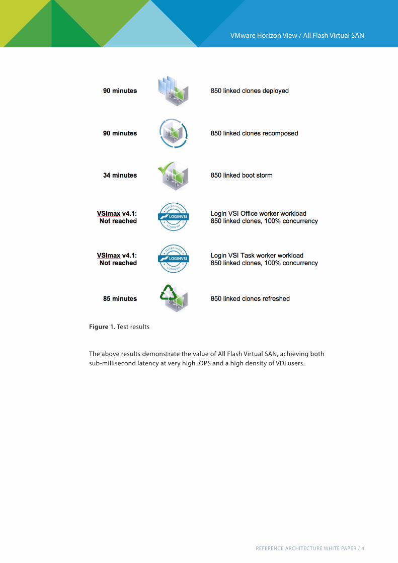
VMware VSAN storage partners SanDisk and Avago helped design the storage tier for this solution. The storage tier is a key component for achieving higher VDI densities with blazingly fast application response times. VMware Virtual SAN network partner Brocade helped design the network tier for this solution. The network tier is an important component in designing the VSAN hypervisor-converged platform to support this VDI environment. The results for four-node All Flash Virtual SAN 6.0 using Dell R730 server hardware are summarized in below table and details are described later in this paper.
REFERENCE ARCHITECTURE WHITE PAPER / 4
VMware Horizon View / All Flash Virtual SAN
The above results demonstrate the value of All Flash Virtual SAN, achieving both sub-millisecond latency at very high IOPS and a high density of VDI users.
Figure 1. Test results

REFERENCE ARCHITECTURE WHITE PAPER / 5
VMware Horizon View / All Flash Virtual SAN
VMware Reference Architecture Overview
VMware reference architectures are built and validated by VMware and supporting partners. They are designed to address common use cases; examples include enterprise desktop replacement or virtual desktop infrastructure (VDI), remote access, business process outsourcing, and disaster recovery. Reference architectures describe in detail the environment and workload used to simulate realistic usage, and draw conclusions based on that particular reference architecture.
This guide is intended to help customers-IT architects, consultants, and administrators involved in the early phases of planning, design and deployment of Horizon with View–based solutions. The purpose is to provide a standard, repeatable, and highly scalable design that can be easily adapted to specific environments and customer requirements.
The reference architecture “building block” approach uses common components to minimize support costs and deployment risks during the planning of large-scale deployments with Horizon View. The building block approach is based on information and experiences from some of the largest VMware deployments in production today. While drawing on existing best practices and deployment guides pertinent to many of the individual specific components, the reference architectures are tested and validated in the field and described in detail.
Some key features that integrate easily into existing IT process and procedure and can help organizations get started quickly with a solution include:
• Standardized, validated, repeatable components • Scalable designs that allow room for future growth • Validated and tested designs that reduce implementation and operational risks • Quick implementation, reduced costs, and minimized risk.
Solution OverviewThis solution is based on best of breed of data center, virtualization and networking technologies, using Dell R730 rack mount servers with local SanDisk solid state drives (SSD) running on vSphere 6.0 with Virtual SAN for desktop workloads with underlying networking infrastructure from Brocade. The Horizon View 6.1 environment runs Windows 7 Enterprise 32-bit virtual desktops provisioned by VMware View Composer™.
The Virtual SAN storage platform for desktop workloads allows the solution to scale linearly, with each host capable of supporting about 200 desktops per host. This reference architecture shows 850 desktops running on four VMware ESXi™ hosts.

REFERENCE ARCHITECTURE WHITE PAPER / 6
VMware Horizon View / All Flash Virtual SAN
Solution Architecture and Hardware
Figure 2. Topology
Figure 3. Hardware Infrastructure

REFERENCE ARCHITECTURE WHITE PAPER / 7
VMware Horizon View / All Flash Virtual SAN
Desktop workloads use four Dell R730 servers, which offer high-density memory, balanced I/O, and the latest processors for enterprise virtualization and business-processing environments. These servers are optimized for running in virtualized and cloud-computing environments and are certified for running VMware vSphere.
Brocade VDX 6740 switches are used to provide network connectivity. Industry-leading Brocade VDX switches are the foundation for high-performance connectivity in Ethernet fabric, storage, and IP network environments. Available in fixed and modular forms, these highly reliable, scalable, and available switches are designed for a wide range of environments, enabling a low Total Cost of Ownership (TCO) and fast Return on Investment (ROI).
For storage, SanDisk Lightning Gen II 12Gb/s SSDs are used in conjunction with VMware Virtual SAN technology to provide a scalable and enterprise-class storage solution. These SSDs are certified for running VMware Virtual SAN and provide sustained performance over a wide range of write-intensive, read-intensive, and mixed-use applications.
Each ESXi host has two disk groups consisting of one mixed-use SSD and three read-intensive SSDs. The two disk groups from each server are combined to form a Virtual SAN datastore.
Software ComponentsThis solution uses the following VMware products:
VMware vSphere 6.0vSphere is the industry-leading virtualization platform for building cloud infra-structures. It enables users to run business-critical applications with confidence and respond quickly to business needs. vSphere accelerates the shift to cloud computingfor existing data centers and underpins compatible public cloud offerings, forming the foundation for the industry’s best hybrid cloud model.
VMware Virtual SAN 6.0Virtual SAN is a hypervisor-converged, software-defined storage platform that is fully integrated with vSphere. Virtual SAN aggregates locally attached disks of hosts that are members of a vSphere cluster to create a distributed shared storage solution. Because Virtual SAN sits directly in the I/O data path, it can deliver the highest levels of performance, scalability, and resilience without taxing the CPU with additional overhead. Virtual SAN enables the rapid provisioning of storage within VMware vCenter™ during virtual machine creation and deployment operations.

REFERENCE ARCHITECTURE WHITE PAPER / 8
VMware Horizon View / All Flash Virtual SAN
Virtual SAN can use an all-flash disk architecture that leverages flash-based mixed-use SSDs for performance and flash based read-intensive SSDs for capacity and persistent data storage. Its distributed datastore is an object-store file system that leverages the vSphere Storage Policy-Based Management (SPBM) feature to deliver centrally managed, application-centric storage services and capabilities. Administrators can specify storage attributes, such as capacity, performance, and availability, as a policy on a per virtual machine basis. The policies dynamically self-tune and load-balance the system so that each virtual machine has the right level of resources.
Horizon View 6.1Horizon View brings the agility of cloud computing to the desktop by transforming desktops into highly available and agile services delivered from your cloud. View delivers virtual sessions that follow end users across devices and locations. It enables fast, secure access to corporate data across a wide range of devices, including Mac OS, Windows, and Linux machines and iOS and Android tablets.
You can use View with VMware vCenter Server™ to create desktops from virtual machines that are running on ESXi hosts and to deploy these desktops to end users. After you create a desktop, authorized end users can use Web-based or locallyinstalled client software to connect securely to centralized virtual desktops, back-end physical systems, or terminal servers. View uses your existing Active Directory infrastructure for user authentication and management.
Figure 4. Virtual SAN Clustered Datastore

REFERENCE ARCHITECTURE WHITE PAPER / 9
VMware Horizon View / All Flash Virtual SAN
Figure 5. Horizon View 6.1 Architecture

REFERENCE ARCHITECTURE WHITE PAPER / 10
VMware Horizon View / All Flash Virtual SAN
Test Methodology
This reference architecture used both Login VSI testing and Horizon View Operation testing as ways to evaluate performance.
Login VSI 4.1 Workload Testing Login Virtual Session Indexer (Login VSI) is the industry-standard benchmarking tool for measuring the performance and scalability of centralized desktop environments. Login VSI gradually increases the number of simulated users until saturation. When the system is saturated, the response times of the applications increase significantly. This latency indicates that the system is almost overloaded. Nearly overloading a system makes it possible to find out what its true maximum user capacity is.
After a test is performed, the response times can be analysed to calculate the maximum active session per desktop capacity. This metric is called VSImax. When the system is approaching its saturation point, response times rise. By reviewing the average response time, you can see that the response time escalates at the saturation point.
The simulated desktop workload is scripted in a 48 to 58-minute loop when a simulated Login VSI user is logged on and performing generic office worker activities. After the loop is finished, it restarts. Within each loop, the response times of 12 operations are measured in a regular interval: 12 times within each loop. The response times of these operations are used to determine VSImax.
Login VSI and VSImax: Summary • VSI tool was used to load the target environment with simulated user workloads and activities. • By gradually increasing the amount of users in the simulation, the system will eventually be saturated. Once the system is saturated, the response time of the applications will increase significantly. • This latency in application response times provides a clear indication whether the system is close to being overloaded. As a result, by nearly overloading a system, it is possible to find out what its true maximum user capacity is. • The point of saturation is represented by the VSImax value.
Figure 6. Login VSI System Components

REFERENCE ARCHITECTURE WHITE PAPER / 11
VMware Horizon View / All Flash Virtual SAN
Horizon View Operations Tests
Provisioning 850 Linked-Clone Desktops In this test, a new pool of 850 linked-clone virtual desktops is provisioned on the Virtual SAN datastore, with about 200 desktops per ESXi host. To complete this task, View Composer creates a replica copy of the base image on the Virtual SAN datastore. View Composer creates and customizes the desktops and joins them to the Active Directory domain. It then takes a snapshot of the virtual desktop, and the desktop goes into an available state.
Refreshing Linked-Clone Desktops In a refresh operation, a virtual desktop reverts to its snapshot. The OS disk of each virtual desktop is restored to its original state and disk size.
Recomposing Linked-Clone Desktops In a recompose operation, a virtual desktop OS disk is changed to a new base image and snapshot. This feature allows administrators to push out patches and software updates with ease. In this operation, View Composer creates a replica of the new base image on the Virtual SAN datastore, creates a new OS disk for each virtual desktop, and deletes the old one. The new desktop is then customized, and a new snapshot created.
Deleting a Pool of Linked-Clone DesktopsThis test deletes a desktop pool, destroying the associated virtual desktops andreplicas.
Boot Storm Desktops This test powers on all the virtual desktops at the same time and measures the VMs boot time once they are up and ready to perform tasks.

REFERENCE ARCHITECTURE WHITE PAPER / 12
VMware Horizon View / All Flash Virtual SAN
Test Results
The test results are described and summarized in the following sections.
Login VSI 4.1 Workload TestingThe test used Login VSI 4.1 to load the system with simulated desktop workloads using common applications like Microsoft Office, Internet Explorer, and Adobe Reader.
The test used Login VSI 4.1 to load the system with simulated desktop workloads using common applications like Microsoft Office, Internet Explorer, and Adobe Reader. The VDI workload in general can be CPU intensive. Virtual SAN can support up to 200 desktops per host from the storage perspective if the host CPU is sized properly. During the LoginVSI testing, we uncovered that our servers were CPU bound under specific workloads. Therefore, we focused our tests on 850 desktops to observe Virtual SAN performance. Two tests were performed with 100% concurrency, first one with task worker workload and second one with office worker workload.
Test 1: 850 Task Worker load Linked-Clone Desktops & Test SummaryIn Test 1, the average host CPU usage reached above 90% on all ESXi hosts around 850 desktops under Task worker workload with 100% concurrency. Despite high CPU usage, VSImax v4.1 was not reached.
Figure 7. Task Worker load with 850 Desktops - VSI Index average graph

REFERENCE ARCHITECTURE WHITE PAPER / 13
VMware Horizon View / All Flash Virtual SAN
The above graph shows that the CPU utilization from all four ESXi servers are below 100% during Login VSI Task worker VDI load.
Figure 8. Task Worker Workload with 850 Desktops - Average application response time graph
Figure 9. ESXi CPU Usage during Login VSI Task Worker Workload

REFERENCE ARCHITECTURE WHITE PAPER / 14
VMware Horizon View / All Flash Virtual SAN
The above figure shows average IOPS from single ESXi server and its related latency. The average latency was below 0.5 ms meeting the sub-millisecond goal of virtual SAN with all flash devices.
Test 1: Summary • VSImax v4.1 not reached at the baseline • CPU usage high • Memory usage was normal • Excellent Virtual SAN client response times, even at maximum load. • Average latency was at sub-millisecond. • Network load was normal in 10 GbE infrastructures.
Test 2: 850 Office Worker load Linked-Clone Desktops & SummaryIn Test 2, the CPU was saturated at 100% usage across all ESXi hosts under Office worker workload with 100% concurrency. Despite very high CPU usage, VSImax v4.1 was not reached.
Figure 10. Single ESXi Server IOPS vs. Latency during Task Worker VDI load

REFERENCE ARCHITECTURE WHITE PAPER / 15
VMware Horizon View / All Flash Virtual SAN
Figure 11. Office Worker load with 850 Desktops - VSI Index average graph
Figure 12. Office Worker load with 850 Desktops - Average application response time graph

REFERENCE ARCHITECTURE WHITE PAPER / 16
VMware Horizon View / All Flash Virtual SAN
The above graph shows the CPU utilization from all four ESXi servers have reached100% during Login VSI Office worker VDI load.
The above graph shows average IOPS from single ESXi server and its related latency. You can see the average latency was below 0.6 ms, meeting the sub-millisecond goal of virtual SAN with all flash devices.
Figure 13. ESXi CPU Usage during Login VSI Office Worker Workload
Figure 14. Single ESXi Server IOPS vs. Latency during Office Worker VDI load

REFERENCE ARCHITECTURE WHITE PAPER / 17
VMware Horizon View / All Flash Virtual SAN
Test 2: Summary • VSImax v4.1 not reached at the baseline • CPU usage high and reached 100 % • Memory usage remained normal • Excellent Virtual SAN client response times, even at maximum load. • Excellent average latency of about 0.6 ms Network traffic load was normal in 10 GbE infrastructures.
Horizon View Operations Testing
Various Horizon View Operation tests were performed such as Deployment / Compose, Decompose, Refresh, Delete and Boot Storm of 850 VMs.
Horizon View Operations Testing Summary • Provisioning 850 Linked-Clone Desktops It took about 90 minutes to provision 850 Windows 7 Enterprise 32-bit, linked-clone virtual desktops and for them to appear in the available state in the View Administrator console. • Refreshing 850 Linked-Clone Desktops It took 85 minutes to refresh 850 Windows 7 Enterprise 32-bit Enterprise 32-bit, linked-clone virtual desktops to their original base image. • Recomposing 850 Linked-Clone Desktops It took approximately 90 minutes to recompose 850 Windows 7 Enterprise 32-bit, linked-clone virtual desktops to a fresh base image. • Deleting a Pool of 850 Linked-Clone Desktops Deleting a pool of 850 linked-clone virtual desktops took 75 minutes. • Boot Storm 850 Desktops It took just under 34 minutes for all the virtual desktops to be ready for user login.
Figure 15. Horizon View Operation Test Results

REFERENCE ARCHITECTURE WHITE PAPER / 18
VMware Horizon View / All Flash Virtual SAN
System Configurations
The following sections describe how the reference architecture components were configured.VMware Virtual SAN integrates with the Horizon View suite. Following main view components were configured during our testing.
View Connection Server Our testing consisted of one View Connection Server. However, a minimum of two connection servers is recommended for production use, each operating in active/active mode.
View Composer Server One View Composer Server was used to deploy 850 VMs.
Test Image ConfigurationWe configured the virtual hardware of the master desktop virtual machine according to standard Login VSI specifications. It is important to note that in production deployments, virtual machine configurations vary based on individual use-case requirements.
vSphere ClustersA four-node Virtual SAN cluster was deployed to support 850 virtual desktops. Each Dell R730 server had an identical configuration and ESXi booted from the local SD card.
Table 1. Test Image Configuration
ATTRIBUTE SPECIFICATION
Desktop OS Microsoft Windows 7 Enterprise
VMware Virtual Hardware Service Pack 1, 32 Bit
Virtual CPU 1
Virtual Memory 1024 MB
vNICs 1
Virtual network adapter 1 E1000
Virtual SCSI controller 0 LSI Logic SAS
Virtual Disk – VMDK 24 GB
VMware Tools version 9.10.0.2476743
VMware Horizon View Agent 6.1.0.2509441
Installed Applications Adobe Acrobat 11
Adobe Flash Player 11.5
Doro PDF 1.82
Internet Explorer 11.0.9600.16428
Microsoft Office 2010
Microsoft Visual Studio 2010

REFERENCE ARCHITECTURE WHITE PAPER / 19
VMware Horizon View / All Flash Virtual SAN
Figure 16. vSphere Cluster Design
Table 2. vSphere Cluster Configuration
The Virtual SAN cluster had the following settings.
PROPERTY SETTING DEFAULT REVISED
Cluster Features HA – Enabled
DRS – -
vSphere HA Host Monitoring Status Enabled –
Admission Control Enabled –
Admission Control Policy Host failures the cluster tolerates = 1 –
Virtual Machine Options > VM restart priority
Medium –
Virtual Machine Options > Host Isolation Response
Leave Powered On –
VM Monitoring Disabled –
Datastore Heartbeating Select any, taking into account my preferences (no datastore preferred)
–
vSphere Storage DRS
Automation Level Fully automated (apply 1,2,3 priority recommendations)
–
DRS Groups Manager – –
Rules – –
Virtual Machine Options – –
Power Management Off –
Host Options Default (Disabled) –
Enhanced vMotion Capability
Disabled –
Swapfile Location Store in the same directory as the virtual machine
–

REFERENCE ARCHITECTURE WHITE PAPER / 20
VMware Horizon View / All Flash Virtual SAN
Virtual SAN
The floating linked clones and replicas use Virtual SAN for storage. Each ESXi host had the same uniform configuration of two disk groups, each disk group consisting of one 800GB mixed-use SSD and three 800GB read-intensive SSDs.
Virtual SAN Storage PolicyVirtual SAN can set availability, capacity, and performance policies per virtual machine if the virtual machines are deployed on the Virtual SAN datastore. The tests used the default storage policy settings, and VMware recommends using the defaults for View 6.1 virtual desktops. For Horizon View 6.1, specific storage-policy recommendations are based on pool type.
Figure 17. Virtual SAN Datastore Components
An additional Virtual SAN node is recommended to make this reference design more resilient and highly available.
Table 3. Virtual SAN Storage Default Settings for View
STORAGE CAPABILITY SETTING
Number of Failures to Tolerate 1
Number of Disk Stripes per Object 1
Force provisioning No
Object Space Reservation 0%
Flash Read Cache Reservation 0 %
REFERENCE ARCHITECTURE WHITE PAPER / 21
VMware Horizon View / All Flash Virtual SAN
Number of Failures to Tolerate (FTT) – This Virtual SAN storage protectionpolicy is applied to each virtual machine. The FTT policy defines how many con-current host, network, or disk failures can occur in the cluster and still ensure the availability of the object. The configuration contains at least FTT+1 copies of the virtual machine and a witness copy to ensure that the object’s data is available even when the number of tolerated failures occurs.
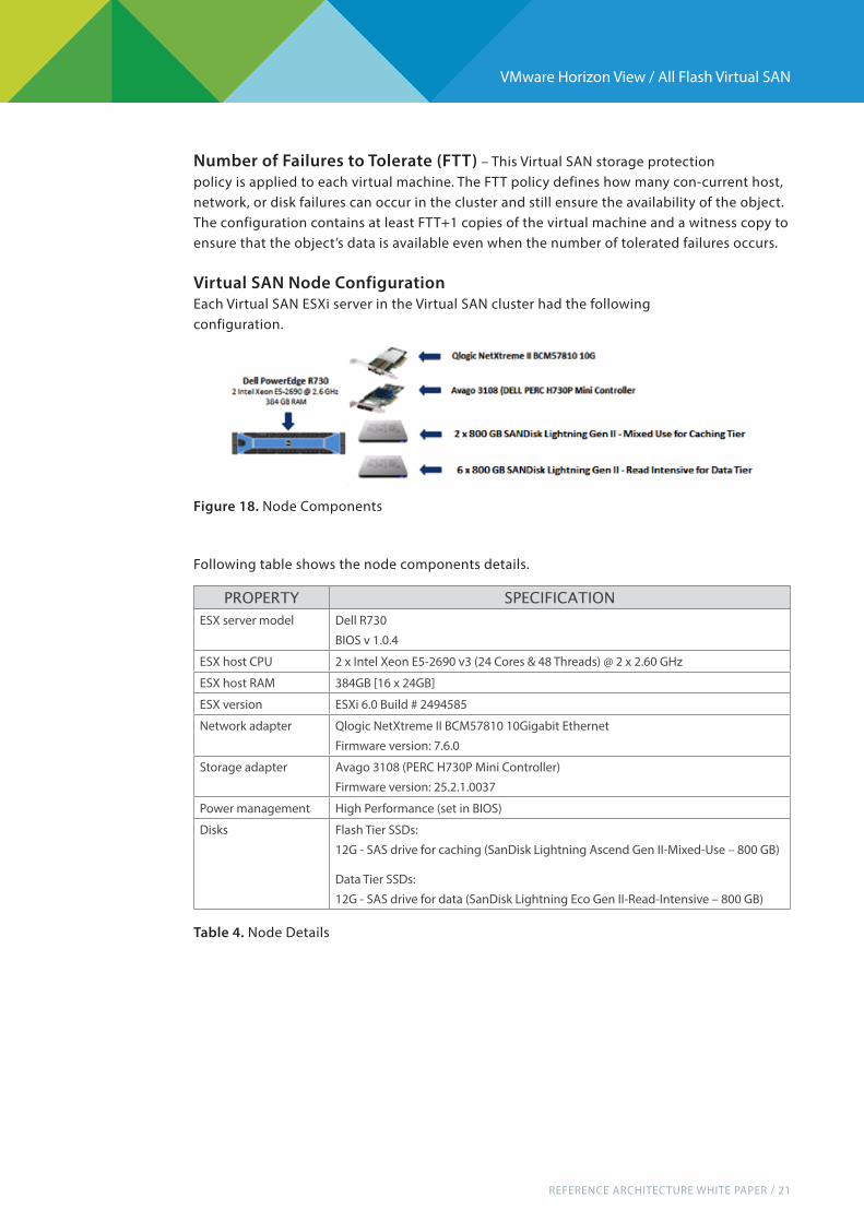
Virtual SAN Node ConfigurationEach Virtual SAN ESXi server in the Virtual SAN cluster had the following configuration.
Following table shows the node components details.
Figure 18. Node Components
Table 4. Node Details
PROPERTY SPECIFICATION
ESX server model Dell R730BIOS v 1.0.4
ESX host CPU 2 x Intel Xeon E5-2690 v3 (24 Cores & 48 Threads) @ 2 x 2.60 GHz
ESX host RAM 384GB [16 x 24GB]
ESX version ESXi 6.0 Build # 2494585
Network adapter Qlogic NetXtreme II BCM57810 10Gigabit EthernetFirmware version: 7.6.0
Storage adapter Avago 3108 (PERC H730P Mini Controller)Firmware version: 25.2.1.0037
Power management High Performance (set in BIOS)
Disks Flash Tier SSDs:12G - SAS drive for caching (SanDisk Lightning Ascend Gen II-Mixed-Use – 800 GB)
Data Tier SSDs:12G - SAS drive for data (SanDisk Lightning Eco Gen II-Read-Intensive – 800 GB)
REFERENCE ARCHITECTURE WHITE PAPER / 22
VMware Horizon View / All Flash Virtual SAN
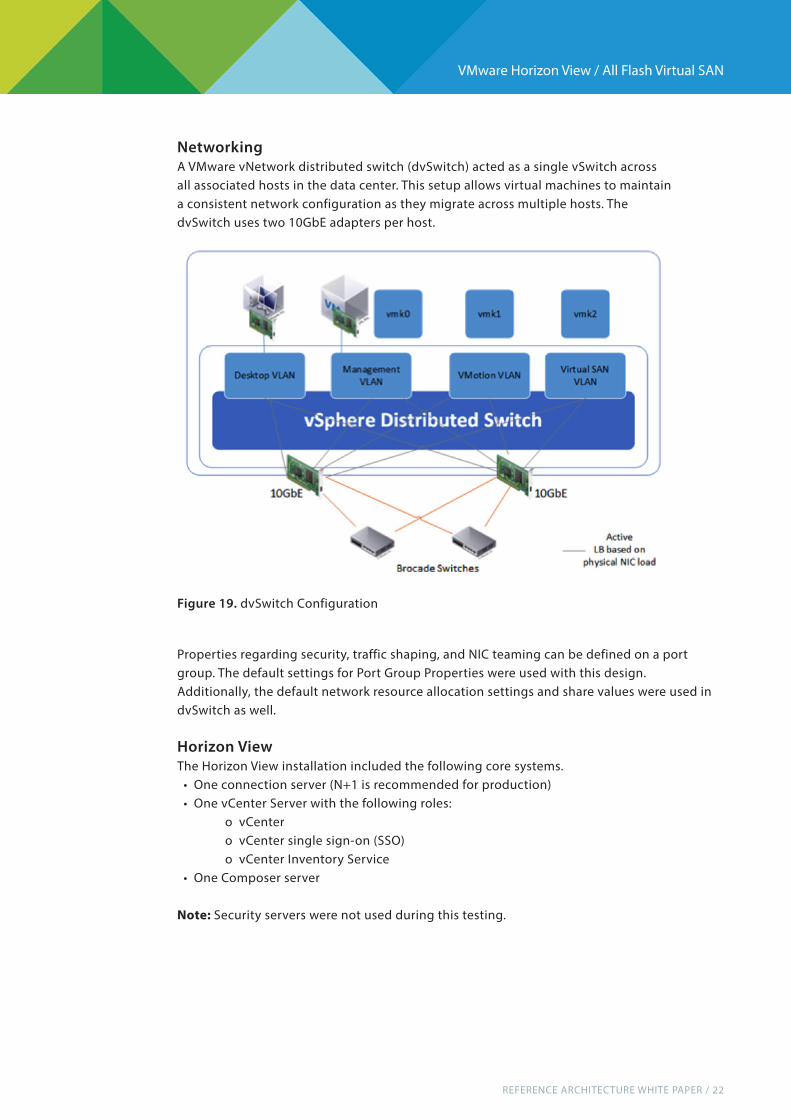
Networking A VMware vNetwork distributed switch (dvSwitch) acted as a single vSwitch acrossall associated hosts in the data center. This setup allows virtual machines to maintain a consistent network configuration as they migrate across multiple hosts. The dvSwitch uses two 10GbE adapters per host.
Properties regarding security, traffic shaping, and NIC teaming can be defined on a port group. The default settings for Port Group Properties were used with this design.Additionally, the default network resource allocation settings and share values were used in dvSwitch as well.
Horizon ViewThe Horizon View installation included the following core systems. • One connection server (N+1 is recommended for production) • One vCenter Server with the following roles: o vCenter o vCenter single sign-on (SSO) o vCenter Inventory Service • One Composer server
Note: Security servers were not used during this testing.
Figure 19. dvSwitch Configuration
REFERENCE ARCHITECTURE WHITE PAPER / 23
VMware Horizon View / All Flash Virtual SAN
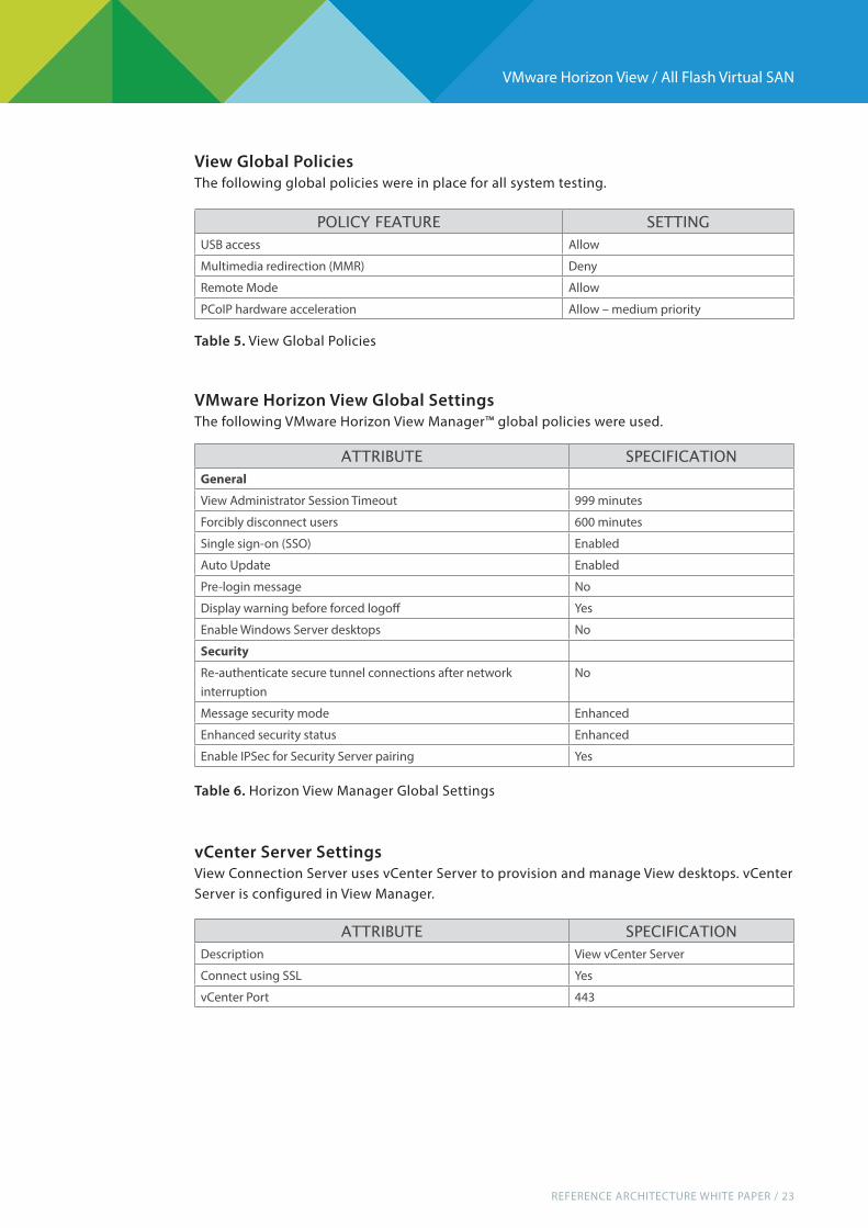
VMware Horizon View Global Settings The following VMware Horizon View Manager™ global policies were used.
vCenter Server SettingsView Connection Server uses vCenter Server to provision and manage View desktops. vCenter Server is configured in View Manager.
POLICY FEATURE SETTING
USB access Allow
Multimedia redirection (MMR) Deny
Remote Mode Allow
PCoIP hardware acceleration Allow – medium priority
Table 5. View Global Policies
Table 6. Horizon View Manager Global Settings
ATTRIBUTE SPECIFICATION
General
View Administrator Session Timeout 999 minutes
Forcibly disconnect users 600 minutes
Single sign-on (SSO) Enabled
Auto Update Enabled
Pre-login message No
Display warning before forced logoff Yes
Enable Windows Server desktops No
Security
Re-authenticate secure tunnel connections after network interruption
No
Message security mode Enhanced
Enhanced security status Enhanced
Enable IPSec for Security Server pairing Yes
ATTRIBUTE SPECIFICATION
Description View vCenter Server
Connect using SSL Yes
vCenter Port 443
View Global PoliciesThe following global policies were in place for all system testing.

REFERENCE ARCHITECTURE WHITE PAPER / 24
VMware Horizon View / All Flash Virtual SAN
View Manager Pool SettingsThe following View Manager pool settings were used.
ATTRIBUTE SPECIFICATION
Advanced Settings:
Maximum Concurrent vCenter Provisioning Operations
Maximum Concurrent Power Operations
Maximum Concurrent View Composer Maintenance Operations
Maximum Concurrent View Composer Provisioning Operations
20
50
12
8
View Composer Port 18443
Enable View Composer Yes
Allow users to choose protocol Yes
Storage Settings:
Reclaim VM disk space
Enable View Storage Accelerator
Default Host Cache Size
√
√
1024MB
Table 7. View Manager – vCenter Server Configuration
ATTRIBUTE SPECIFICATION
General Never
Desktop Pool Naming
Desktop Pool Attributes Automated, linked clone, floating
Desktop Pool ID Desktops
Display Name Desktops123
Access Group /
View Composer Disks
Disposable disk size 4096 MB
Disposable disk drive letter Auto
Storage Policy Management
Use VMware Virtual SAN Yes - Select
Do not use VMware Virtual SAN No - Select
Desktop Pool Settings
General
State Enabled
Connection Server Restriction None
Remote Settings
Remote Machine Power Policy Take no power action
Automatically logoff after disconnect Never
Allow users to reset their machine No
Allow user to initiate separate sessions from different client device No

REFERENCE ARCHITECTURE WHITE PAPER / 25
VMware Horizon View / All Flash Virtual SAN
ATTRIBUTE SPECIFICATION
Delete or refresh machine at logoff Never
Remote Display
Default display protocol PCoIP
Allow users to choose protocol Yes
Max number of monitors 2
Max resolution of any monitor 1920x1200
HTML Access Not Enabled
Adobe Flash Settings for Sessions
Adobe Flash quality Do not control
Adobe Flash throttling Disabled
Mirage Settings
Override global Mirage settings Not Selected
Provisioning Settings
Basic
Enable Provisioning √
Stop Provisioning on error √
Virtual Machine Naming
Name Type Use a naming pattern
Naming Pattern VM-{n:fixed=3}
Desktop Pool Sizing
Max number of machines 2
Number of spare (powered on) machines 2
Minimum number of ready (provisioned) machines during View Composer maintenance operations
0
Provisioning Timing
Provision machine on demand Not Select
Provision all machines up-front Select
Advanced Storage
Advanced Storage Settings
Use View Storage Accelerator Selected
Disk Types OS Disks
Regenerate storage accelerator after 7 Days
Blackout Times Not Selected
Transport Page Sharing Scope Virtual Machine
*Virtual SAN does not support the space-efficient (SE) sparse disk format.
Table 8. View Manager – Test Pool Configuration

REFERENCE ARCHITECTURE WHITE PAPER / 26
VMware Horizon View / All Flash Virtual SAN
Bill of Materials
The following table summarizes the bill of materials for this reference architecture.
AREA COMPONENT QUANTITY
Host hardware Dell PowerEdge R730 4
Intel Xeon E5-2690 v3 @ 2.60GHz 2
384GB RAM 24 x 16 GB
PERC H730P Mini 1
Qlogic NetXtreme II BCM57810 10Gigabit Ethernet
1
1GB SD Card 1
12G - SAS drive for caching (SanDisk Lightning Ascend Gen II-MU* – 800 GB * Mixed-use
2
12G - SAS drive for data (SanDisk Lightning Eco Gen II-RI**– 800 GB) ** Read-intensive
6
Network Switch Brocade VDX 6740 2
Software VMware ESXi 6.0,2494585 7
VMware vCenter Server 6.0, 2559268 1
View 6.1.0 – 2509221 1
Microsoft Windows 2008 R2 4
Microsoft SQL Server 2008 R2 1
Table 9. Bill of Materials

REFERENCE ARCHITECTURE WHITE PAPER / 27
VMware Horizon View / All Flash Virtual SAN
Conclusion
VMware Virtual SAN is a cost-effective, high-performance storage platform that can be rapidly deployed, easily managed, and is fully integrated into the industry-leading VMware infrastructure Using SSDs in an all-flash Virtual SAN solution offers significant improvements in performance while reducing other OpEx costs such as maintenance, power consumption, and cooling costs.
The all-flash Virtual SAN described here easily scales as your VDI user base grows, keeping CapEx costs down and eliminating the need for the large upfront investment that traditional storage arrays often require.
Extensive workload, operations, and resiliency testing shows that Horizon with View on Virtual SAN delivers high levels of performance, a great end-user experience, and solid system resiliency, all at a low price point.
While all-flash storage arrays are traditionally seen as expensive, combining a virtualized SAN with all-flash storage is a cost-effective and robust solution that can be a perfect fit for enterprises that are looking for predicable performance and reliable storage at a lower acquisition and operating costs.
REFERENCE ARCHITECTURE WHITE PAPER / 28
VMware Horizon View / All Flash Virtual SAN
About the Authors
Abid Saeed is a lead architect of this Reference Design. He has over 15 years of experience in Storage, Virtualization, Cloud Computing, and Business Critical Applications. He is currently working for VMware as a Solution Architect in which he provides technical solutions with various storage partners, such as HP Storage, Network Appliance, EMC, Avago and SanDisk. Before VMware, he held senior engineering positions at Brocade and Adaptec, workings with storage industry partners on ground breaking technologies of its time.
Sameer Pandya is a R&D Manager at VMware. He has industry experience of around 20 years having worked at Lucent Technologies, AT&T Labs and HP. He is working closely with various VMware technologies and guides Solution Architects navigate integration of partner technologies on VMware platform.
Nanjunda Somayaji is currently a senior technical manager at Brocade. He has more than 20 years of experience in the industry with tenures at Amdahl, Sun Microsystems and VMware prior to joining Brocade., In his current role he closely works with Brocade and VMware Product Groups and Engineering as a Partner Solution Architect to define and architect Cloud based solutions involving Brocade and VMware products and technologies.
Biswapati Bhattacharjee is a Technical Marketing Manager at SanDisk and has been with VMware virtualization technology for a while. Previously, Biswapati worked with many VMware ISV partners in enabling their applications in server (vSphere), desktop (VDI) and BCDR (SRM) platform and product of VMware.
AcknowledgementsThis reference architecture is the result of collaboration between VMware, Avago, DELL, SanDisk and Brocade. Many folks within the companies contributed to the success of this reference architecture.

REFERENCE ARCHITECTURE WHITE PAPER / 29
VMware Horizon View / All Flash Virtual SAN
ReferencesView Documentationhttps://www.vmware.com/support/pubs/view_pubs.html
View Technical Resourceshttp://www.vmware.com/products/desktop_virtualization/view/technical-resources.html
View Optimization Guide for Windows 7 and Windows 8http://www.vmware.com/resources/techresources/10157
View Storage Acceleratorhttp://www.vmware.com/resources/techresources/10334
VMware vCenter Database: Performance Improvements + Best Practice for Large-Scale Environments http://www.vmware.com/files/pdf/techpaper/VMware-vCenter-DBPerfBestPractices.pdf
Dell PowerEdge R730http://i.dell.com/sites/doccontent/shared-content/data-sheets/en/Documents/Dell-PowerEdge-R730-Spec-Sheet.pdf Brocade VDX 6740http://www.brocade.com/downloads/documents/data_sheets/product_data_sheets/brocade-vdx-6740-ds.pdf
Qlogic NetXtreme II BCM57810 10Gigabit Ethernethttp://www.qlogic.com/OEMPartnerships/Dell/Documents/lc_QLogic_Adapters.pdf DELL PERC H730Phttp://i.dell.com/sites/doccontent/shared-content/data-sheets/en/Documents/Dell-PowerEdge-RAID-Controller-H730P.pdf
Virtual SAN Sizing Guide for VDI and other technical resourceshttp://www.vmware.com/products/virtual-san/resources.html
Virtual SAN Hardware Quick Start Guidehttps://www.vmware.com/files/pdf/products/vsan/vmware-virtual-san-hardware-quick-start-guide.pdf
Virtual SAN Design and Sizing Guidehttp://www.vmware.com/files/pdf/products/vsan/VSAN_Design_and_Sizing_Guide.pdf
SanDisk SAS Solid State Driveshttp://www.sandisk.com/enterprise/sas-ssd/

REFERENCE ARCHITECTURE WHITE PAPER / 30
VMware Horizon View / All Flash Virtual SAN
Appendix: Partner Products
Brocade Networking The solution networking utilizes Brocade VDX 6740 switches based on Brocade Virtual Cluster Switching (VCS) technology—a revolutionary Layer 2 Ethernet capability that improves network utilization, maximizes application availability, increases scalability, and dramatically simplifies the network architecture in next-generation virtualized data centers.
The traditional network architecture, one used in data centers for the past several decades is shown in Figure 20. One of the huge limitations of this architecture is the use of Spanning Tree Protocol (STP) to prevent loops, which significantly limits network utilization. In addition, each of the switches on the network needs to be managed individually.
Together with Brocade VCS Fabric technology, these switches can simplify network design and operations for a more automated, high performance and efficient network. These switches also offer the flexibility needed to easily scale networks, and provide a highly available, cloud-ready infrastructure.
Brocade VCS technology enables IT organizations to flatten and seamlessly scale out the Layer 2 network at the edge as shown in Figure 21. All the switches participating in the fabric can be managed as a single logical physical switch.
Figure 21. Brocade Ethernet Fabric Architecture
Figure 20. Classical Ethernet Architecture
REFERENCE ARCHITECTURE WHITE PAPER / 31
VMware Horizon View / All Flash Virtual SAN
Brocade VCS FeaturesThe following Brocade VCS features are considered best practices when utilizing Virtual SAN over a Brocade VCS fabric for a VDI solution.
vCenter Integration for Automatic Migration of Port Profile (AMPP)While validating All Flash Virtual SAN-based VDI solution, the configured VLANs such as Desktop VLAN, Management VLAN, vMotion VLAN, and Virtual SAN VLAN are configured at Distributed vSwitch. By leveraging the vCenter integration for AMPP feature, the above mentioned VLANs were automatically configured in the physical network thus providing zero touch configuration.
Brocade Inter-Switch Link (ISL) TrunksInstead of LAG-based switch interconnects, Brocade VCS Ethernet fabrics automatically form ISL trunks when multiple connections are added between two Brocade VDX switches. Simply adding another cable increases bandwidth, providing linear scalability of switch-to-switch traffic, and this does not require any configuration on the switch. In addition, ISL trunks use a frame-by-frame load balancing technique, which evenly balances traffic across all members of the ISL trunk group.
Equal-Cost Multipath (ECMP)A standard link-state routing protocol that runs at Layer 2 determines if there are Equal-Cost Multipath (ECMP) between switches (also called RBridges) in an Ethernet fabric and load balances the traffic to make use of all available ECMPs. If a link fails, traffic is automatically distributed to other available equal-cost paths with minimal delay.
Virtual Link Aggregation Group (vLAG)Static Link Aggregation Control Protocol (LACP) Virtual Link Aggregation Groups (vLAGs) are used for the ESXi hosts, which are also Virtual SAN nodes.While Brocade ISLs are used as interconnects between Brocade VDX switches within a Brocade VCS fabric, industry standard LACP LAGs are supported for connecting to other network devices outside the Brocade VCS fabric.
Pause Flow ControlBrocade VDX Series switches support the Pause Flow Control feature. Pause Flow Control is enabled on vLAG-facing interfaces connected to the ESXi hosts. Pause and Priority-Based Flow Control (PFC) are used to prevent dropped frames by slowing traffic at the source end of a link.
Ultra-Low LatencyThe Brocade VDX series of switches provides industry-leading performance and ultra-low latency through wire-speed ports with 600 nano-second port-to-port latency and hardware-based Brocade ISLTrunking. This is helpful for environments that require high availability, such as providing Virtual SAN, Internet Small Computer Systems Interface (iSCSI), and NAS.
Jumbo FramesBrocade VDX Series switches support the transport of jumbo frames. Jumbo framesare enabled by default on the Brocade ISL trunks. The default Maximum Transmission Unit (MTU) on these interfaces is 2500. This MTU is set to 9216 to optimize the network for jumbo frame support.

REFERENCE ARCHITECTURE WHITE PAPER / 32
VMware Horizon View / All Flash Virtual SAN
SanDisk SSDs
The Virtual SAN all-flash architecture allows tiering of flash-based devices. The design of this tiering is that the top tier will serve the write buffer need and the bottom tier will serve the read cache as well as persistent storage of data.
From a flash perspective, VMware recommends using a performance, write-intensive, high-endurance caching tiers for the writes and a read-intensive, durable cost-effective flash-based device tier for data persistence. Based on above guidelines, SanDisk Lightning Ascend Gen II drives are chosen for cache tier and Lightning Eco Gen II drives chosen for capacity tier. These drives are meant to address the need for cache and capacity tier.
Lightning Ascend™ Gen. IIThe Lightning Ascend™ Gen. II 12Gb/s SAS SSD doubles interface speed, providing the highest performance for mission-critical hyperscale, cloud and virtualized data center application workloads. This next generation Lightning® SSD offers a feature-rich robust design, combined with SanDisk’s innovative parallel processing architecture to deliver full data path protection (T10-DIF support), temperature based power control, SED instant secure erase, an MTBF of 2.5 million hours and power fail protection. This SSD is backward-compatible with 6Gb/s SAS and offers a single firmware binary platform for seamless integration and reduced qualification times. Lightning Ascend Gen. II SAS SSDs offer superior reliability with high-speed data transfer rates where quick access to data is essential. These SSDs are available in 19nm eMLC capacities from 200GB – 1.6TB2 with random read/write performance of up to 190K/80K IOPS and sequential read/write speed of up to 1000/600 MB/s. These SSDs are designed for mixed-use applications such as On-line Transaction Processing (OLTP) Databases, Email/Messaging, E-Commerce, Virtual Desktop Infrastructure, and Collaboration with a typical workload comprised of a 70/30 read/write mix. This SSD offers 10 full drives writes per day (DWPD) and an ideal fit for Virtual SAN cache tier. Lightning Eco™ Gen. IIThe Lightning Eco™ Gen. II 12Gb/s SAS SSD doubles interface speed, providing the highest performance for mission-critical hyperscale, cloud and virtualized data center application workloads. This next generation Lightning® SSD offers a feature rich robust design, combined with SanDisk’s custom controller and innovative parallel processing architecture to deliver full data path protection (T10-DIFsupport), temperature based power control, SED instant secure erase, an MTBF of 2.5 million hours, and power fail protection.
This SSD is backward-compatible with 6Gb/s SAS and offers a single firmware binary platform for seamless integration and reduced qualification times Lightning Eco™ Gen. II SAS SSDs offer solid I/O cost to performance benefits with low latency data access for high quality of service (QoS). These SSDS are available in 19nm eMLC capacities from 800GB - 1.6TB2 with random read/write performance of up to 180K/35K IOPS and sequential read/write speed of up to 1000/500 MB. These SSDs are designed for read-intensive applications such as Data Warehousing, Media Streaming, Video on Demand (VOD), Web-based Applications, Virtual Tape Libraries (VTL) and File Servers, with a heavy read workload comprised of a 90/10 read/write mix. This SSD offers 3 full drives writes per day (DWPD) and an ideal fit for Virtual SAN capacity tier.