vm series - xylem applied water
TRANSCRIPT

VM SeriesCLOSE-COUPLED THREADED VERTICAL MULTISTAGE CENTRIFUGAL ELECTRIC PUMPS
50 Hz
Cod. 191003611 Rev. C Ed.02/2019
ErP 2009/125/CE

2
Noryl is a trademark of SABIC Innovative Plastics Company.Lowara, HYDROVAR, Xylect are trademarks of Xylem Inc. or one of its subsidiaries.

3
CONTENTS
GENERAL INTRODUCTION ..................................................................................................................................5APPLICATIONS, BENEFITS – BUILDING SERVICES ..................................................................................................6GENERAL CHARACTERISTICS / IDENTIFICATION CODE .........................................................................................7ELECTRIC PUMP RATING PLATE / MECHANICAL SEAL ..........................................................................................81, 3, 5, 10 VM..P SERIES ELECTRIC PUMP CROSS SECTION AND MAIN COMPONENTS .........................................9MOTORS ......................................................................................................................................................10PUMPS .........................................................................................................................................................13HYDRAULIC PERFORMANCE RANGE AT 50 Hz, 2 POLES ................................................................................14HYDRAULIC PERFORMANCE TABLE AT 50 Hz, 2 POLES ..................................................................................15DIMENSIONS AND WEIGHTS, OPERATING CHARACTERISTICS AT 50 HZ, 2 POLES ..........................................16VM WITH VARIABLE FREQUENCY DRIVE .......................................................................................................25VME VERSION WITH DRIVE AND PERMANENT MAGNET MOTOR (e-SM DRIVE) .............................................27ACCESSORIES ...............................................................................................................................................55REPORTS AND DECLARATIONS .....................................................................................................................59TECHNICAL APPENDIX ..................................................................................................................................61

4

5
VM SERIESGENERAL INTRODUCTIONOur customers are central to our business.
Many years of collaboration with them across the different markets and all over the world has taught us that the Building Services market requires specific pump design to meet the challenge of the energy saving and market competitiveness, also through performances and reliability. Therefore Lowara has developed a new range of single piece vertical multistage pumps, the VM, to give an appropriate and dedicated solution to special applications and installations in the residential and commercial building services market.
Pump designThe VM is a non-self-priming vertical multistage, high pressure centrifugal pump, with threaded inlet and outlet manifolds. The pumps are close-coupled design and are equipped with non-standard Lowara motors. The VM is equipped with mechanical seal. The VM are highly modular pumps that are fitted with an innovative hydraulic design that secures high efficiency performances and an increased Mean Time Between Failure. The VM is available in four different sizes; the design is made of a cast iron pump body coupled to an external stainless steel (EN 1.4301/ AISI 304) TIG welded sleeve with the mean of stainless steel tie rods screwed in the aluminium motor flange. The impellers are made in Noryl.
MotorThe VM are equipped with Lowara designed and manufactured surface motors in accordance with EN standards. The VM series can be equipped as well with Lowara variable speed drivers.
Range declinationThe VM series are available as:
- Single pump.- Variable speed system.
SPECIFICATIONSPUMP- Flow rate: up to 14 m3/h.- Head: up to 98 m.- Ambient temperature:• Three-phase motor versions from -15°C to +50°C.• Single-phase motor versions from -15°C to +45°C (from -15°C to +40°C for 3VM02P and all models with 0,95 kW motor).
- Temperature of the pumped liquid:• +90°C for versions with three-phase motor uses as EN 60335-2-41.• +60°C for versions with single-phase motor.
- Maximum operating pressure: 10 bar (PN 10).- Connections: Rp threaded for both suction and discharge manifold.- Hydraulic performances compliant with ISO 9906:2012 - Grade 3B.
MARKET SECTORSBUILDING SERVICES.
APPLICATIONS• Pressure boosting and water supply
systems.• Small to medium irrigation systems.• Liquid handling systems.
The VM pumps for drinking water use are WRAS, ACS e D.M. 174 certified.
MOTOR- Electric short-circuit squirrel-cage motor
(TEFC), enclosed construction, air-cooled, 2-pole:• Three-phase, efficiency class IE3 (compliant
with Regulation (EC) n. 640/2009 and IEC 60034-30).• Single-phase version up to 2,2 kW (with
built-in automatic reset overload protection).- IP55 protection degree.- Insulation class 155 (F).- Performances according to EN 60034-1.- Standard voltage:• Single-phase: 220-240V, 50 Hz.• Three-phase: 220-240/380-415V, 50 Hz up to 3 kW.

6
VM SERIESAPPLICATIONS, BENEFITS – BUILDING SERVICES
ApplicationsThe VM series could be installed both in single private own house and in small/medium residential buildings.The VM series will be as well your preferred choice for water supply and pressure boosting in small block offices and shops. The VM series could be finally installed as well for small/medium irrigation installation.
BenefitsEase of installation: thanks to the limited dimensions due to the close-coupled vertical design, the VM is easy to handle and install.
Payback: Installing the VM series guarantee a very short payback period thanks to the high performance and to the competitive market positioning.
Reliability: The VM series secures as well reliable operations over time thanks to its robust and innovative design, heritage of the e-HMTM. This could be increased with the installation of the e-SM Drive: variable speed operation reduces mechanical stress on the pump components and water hammering during stopping.
Comfort: The VM series guarantee as well an increased user comfort thanks to very silent operation. The combination of the VM series with the e-SM Drive will secure constant pressures at any points of water in your building and constant temperatures even when other taps are opened!
Features - Compact design with best-in class performances. - Wide range of performances with 4 sizes and flow up to 14m3/h. - Nominal pressure up to 10 bars. - Robust and silent design due the sleeve configuration. - IE3 Lowara manufactured motors: high performances and silent operations. - “Essential O-ring design” that highly reduces the sealing weaknesses (Only 2 OR in the sleeve design).
The VM series have been designed to cover a wide range of applications in the residential and small commercial buil-ding services from water supply to pressure boosting.

7
CARATTERISTICHE GENERALI 1-3-5-10 HMP 2 POLI 50 Hz
Max efficiency flow (m3/h) 1,8 3,0 5,0 10,6
Flow range (m3/h) 0,7÷2,4 1,2÷4,2 2,4÷7,2 5÷14
Maximum head ( m ) 92 96 99 93
Motor power ( kW ) 0,30÷1,1 0,30÷1,5 0,40÷2,2 1,1÷3
Max η ( % ) of pump 39 47 56 62
Minimum efficiency index MEI ( ≥ ) 0,7 0,7 0,7 0,7
Standard temperature ( °C )
1-10vmp_2p50-en_a_tg
-30 +90
VM..P SERIES 3 5 101
VERSIONI 1-10VM
1 3 5 10Rp thread (suction) Rp 1 Rp 1 Rp 1 1/4 Rp 1 1/2
Rp thread (delivery) Rp 1 Rp 1 Rp 1 1/4 Rp 1 1/2
1-10vm_2p50-en_a_tc
CONNECTION TYPEVM..P SERIES
VM SERIESGENERAL CHARACTERISTICS
CONNECTIONS
-40°C to +60°CSTORAGE AND TRANSPORT TEMPERATURE
IDENTIFICATION CODE
EXAMPLE: 10VM05P30T5RVBE10 = Flow rate 10 m3/h, VM = VM series electric pump, 05 = number of impellers 5, P = P version (Noryl impellers), 30 = 3 kW rated motor power, T = three-phase, 5R = 50 Hz voltage 220-240/380-415V, VBE = Aluminium/Carbon mechanical seal and EPDM elastomers.
EXAMPLE: 10VME02P11M02VBE10 = Flow rate 10 m3/h, VM = VM series electric pump, E = e-SM (SMART) coupling, 02 = number of impellers 2, P = P version (Noryl impellers), 11 = 1,1 kW rated motor power, M = single-phase, 02 = e-SM power supply 1x208-240, VBE = Aluminium/Carbon mechanical seal and EPDM elastomers.
Flow rate [1 or 2 digits]10 = m3/h
Series name [2 digits]VM
Motor operation [1 digit]Null = Standard asynchronous motorH = Equipped with HYDROVAR X = Other drivesE = e-SM drive
Number of impeller [2 digits]03 = 3 impellers
Motor power [2 digits]kW x 10
1 0 V M E 0 2 P 1 1 M 0 2 V B E
Material [1 digit]P = Stainless steel (AISI 304) with Noryl impellers
Phase [1 digit]M = Single-phaseT = Three-phase
Electrical Voltage [2 digits]
50 Hz std asynchronous motor5H = 1x220-240 V5R = 3x220-240/380-415 V
60 Hz std asynchronous motor6F = 1x220-230 V6P = 3x220-230/380-400 V
e-SM Power supply02 = 1x208-240 V04 = 3x380-460 V05 = 3x208-240/380-460 V
Mech. seal rotating part [1 digit]V = Aluminium oxide (Ceramic)
Mech. seal stationary part [1 digit]B = Carbon resin impregnated
Elastomers [1 digit]E = EPDM
GENERAL CHARACTERISTICS / IDENTIFICATION CODE

8
VM SERIESELECTRIC PUMP RATING PLATE
2 - Capacity range 3 - Head range 4 - Minimum head (EN 60335-2-41) 6 - Frequency 7 - Maximum operating pressure 8 - Electric pump unit absorbed power 9 - Pump / electric pump unit type11 - Electric pump unit / pump part number12 - Protection degree13 - Maximum operating liquid temperature (uses as EN 60335-2-41)15 - Rated voltage range16 - Serial number (date + progressive number)18 - MEI index (Regolation (EU) n. 547/2012) 19 - Maximum operating ambient temperature20 - Electric pump weight
LEGEND
MECHANICAL SEAL
LIST OF MATERIALS ACCORDING TO EN 12756
TYPE OF SEAL
TENUTA MECCANICA 1-10 VM MATERIALI
V : Aluminium oxide (Ceramic) E : EPDM G : AISI 316 B : Carbon, resin-impregnated
1-10vm_ten-mec-en_a_tm
POSITION 1 - 2 POSITION 3 POSITION 4 - 5
TENUTA MECCANICA VM COMBINAZIONI
*TEMPERATURE OPERATING1 2 3 4 5 PRESSURE
ROTATING PART STATIONARY PART ELASTOMERS SPRINGS OTHER COMPONENTS
VBEGG V B E G G -30 + 90 PN10
* For single-phase versions limit the temperature to +60°C. 1-10vm_tipi-ten-mec-en_a_tc
TYPE
STANDARD MECHANICAL SEAL
POSITION
( °C )
ELECTRIC PUMP RATING PLATE / MECHANICAL SEAL
9
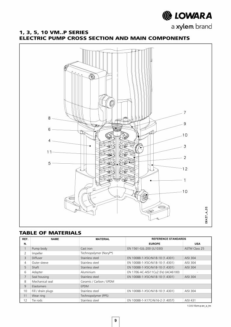
1, 3, 5, 10 VM..P SERIES ELECTRIC PUMP CROSS SECTION AND MAIN COMPONENTS
TABLE OF MATERIALSMATERIALI 1-3-5-10 VM VERSIONI P
REF. NAME MATERIAL
N. EUROPE USA
1 Pump body Cast iron EN 1561-GJL-200 (JL1030) ASTM Class 25
2 Impeller
3 Diffuser Stainless steel EN 10088-1-X5CrNi18-10 (1.4301) AISI 304
4 Outer sleeve Stainless steel EN 10088-1-X5CrNi18-10 (1.4301) AISI 304
5 Shaft Stainless steel EN 10088-1-X5CrNi18-10 (1.4301) AISI 304
6 Adapter Aluminium EN 1706-AC-AlSi11Cu2 (Fe) (AC46100) -
7 Seal housing Stainless steel EN 10088-1-X5CrNi18-10 (1.4301) AISI 304
8 Mechanical seal Ceramic / Carbon / EPDM
9 Elastomers EPDM
10 Fill / drain plugs Stainless steel EN 10088-1-X5CrNi18-10 (1.4301) AISI 304
11 Wear ring Technopolymer (PPS)
12 Tie rods Stainless steel EN 10088-1-X17CrNi16-2 (1.4057) AISI 431
1-3-5-10vm-p-en_a_tm
REFERENCE STANDARDS
Technopolymer (Noryl™)

10
VM SERIESMOTORS
SINGLE-PHASE MOTORS AT 50 Hz, 2-POLE
ErP 2009/125/EC
• Standard three-phase surface motors ≥ 0,75 kW supplied as IE3.• Short-circuit squirrel-cage motor, enclosed construction with external ventilation (TEFC).• IP 55 protection degree.• Insulation class 155 (F).• Electrical performances according to EN 60034-1.• IE efficiency according to EN 60034-30 (≥ 0,75 kW).• Cable gland with metric according to EN 50262.
• Single-phase version: 220-240 V 50 Hz Built-in automatic reset overload protection up to 2,2 kW.• Three-phase version: 220-240/380-415 V 50 Hz for power up to 3 kW. 380-415/660-690 V 50 Hz for power above 3 kW. Overload protection to be provided by the user.
With the “Energy using Products” (EuP 2005/32/EC) and “Energy related Products” (ErP 2009/125/EC) directives, the European Commission has established requirements for promoting the use of products with low power consumption.
The various products considered include three-phase 50 Hz surface motors with power outputs ranging from 0,75 to 375 kW, also when integrated with other products, with characteristics as defined by the specific Regulations (EC) No 640/2009 and (EU) No 4/2014 implementing the requirements of the EuP and ErP Directives.
In accordance with regulations, the three-phase 50 Hz surface motors with power outputs ranging from 0,75 to 375 kW have IE3 as minimum level of efficiency or IE2 fitted with variable speed drive. IE2 motor can be supplied without frequency converter as the obligation to have that device is related to when the motor is working and not when placed on the market.
ηηηη ϕϕϕϕ

11
VM SERIESTHREE-PHASE MOTORS AT 50 Hz, 2-POLE
ϕϕϕϕ
V
∆∆∆∆∆∆∆∆
ηηηη
∆∆∆∆ ∆∆∆∆ ∆∆∆∆ ∆∆∆∆
∆ ∆ ∆ ∆
∆∆∆∆

12
VM SERIESELECTRIC PUMP NOISE
Surface motors - Standard voltages offering -- Motori di superficie - specchietto tensioni disponibile
1 x
220-
240
1 x
100
1 x
110-
120
1 x
220-
230
1 x
100
1x 1
10-1
15
1 x
120-
127
1 x
200-
210
3 x
220-
230-
240/
380-
400-
415
3 x
380-
400-
415/
660-
690
3 x
200-
208/
346-
360
3 x
255-
265/
440-
460
3 x
290-
300/
500-
525
3 x
440-
460/
-
3 x
500-
525/
-
3 x
220-
230/
380-
400
3 x
255-
265-
277/
440-
460-
480
3 x
380-
400/
660-
690
3 x
440-
460-
480/
-
3 x
110-
115/
190-
200
3 x
200-
208/
346-
360
3 x
330-
346/
575-
600
3 x
575/
-
3 x
230/
400
50 H
z3
x 26
5/46
0 60
Hz
3 x
400/
690
50 H
z3
x 46
0/-
60 H
z
0,50 s - - s - o - - 0,30 s o o o o o o s o o o o o o o o o0,55 s o o s o o o o 0,40 s o o o o o o s o o o o o o o o o0,75 s o o s o o o o 0,50 s o o o o o o s o o o o o o o o o0,95 s o o s o o o o 0,55 s o o o o o o s o o o o o o o o o1,1 s - o s - o - o 0,75 s o o o o o o s o o o o o o o o o1,5 s - - s - o - o 1,1 s o o o o o o s o o o o o o o o o2,2 s - - s - - - - 1,5 s o o o o o o s o o o o o o o o o
2,2 s o o o o o o s o o o o o o o o o3 s o o o o o o s o o o o o o o o o
s = Standard voltage o = voltage upon request - = Not available vm-volt-lowa-en_b_te
THREE-PHASE
PN
kW
SINGLE-PHASE
50 Hz 60 Hz
PN
kW
50/60 Hz50 Hz 60 Hz
Tolerances on nominal voltages
The tables below show the mean sound pressure levels (Lp) measured at 1 meter distance in a free field according to EN ISO 11203. The noise values are measured on 50 Hz motors and have a tolerance of 3 dB (A) according to EN ISO 4871.
RUMOROSITA' MOTORI VM 2-POLI 50Hz
POWER
kW
0,300,400,500,550,750,951,11,52,23
1-10vm_mot_2p50-en_a_tr
60
52
52555555
52
60
6060
NOISELpA
dB
AVAILABLE MOTOR VOLTAGES, 2-POLE
•50 Hz:±10% on the single voltage value shown on the rating plate.±5% on voltage range shown on the rating plate.
•60 Hz:±10% on the voltage values shown on the rating plate.
13
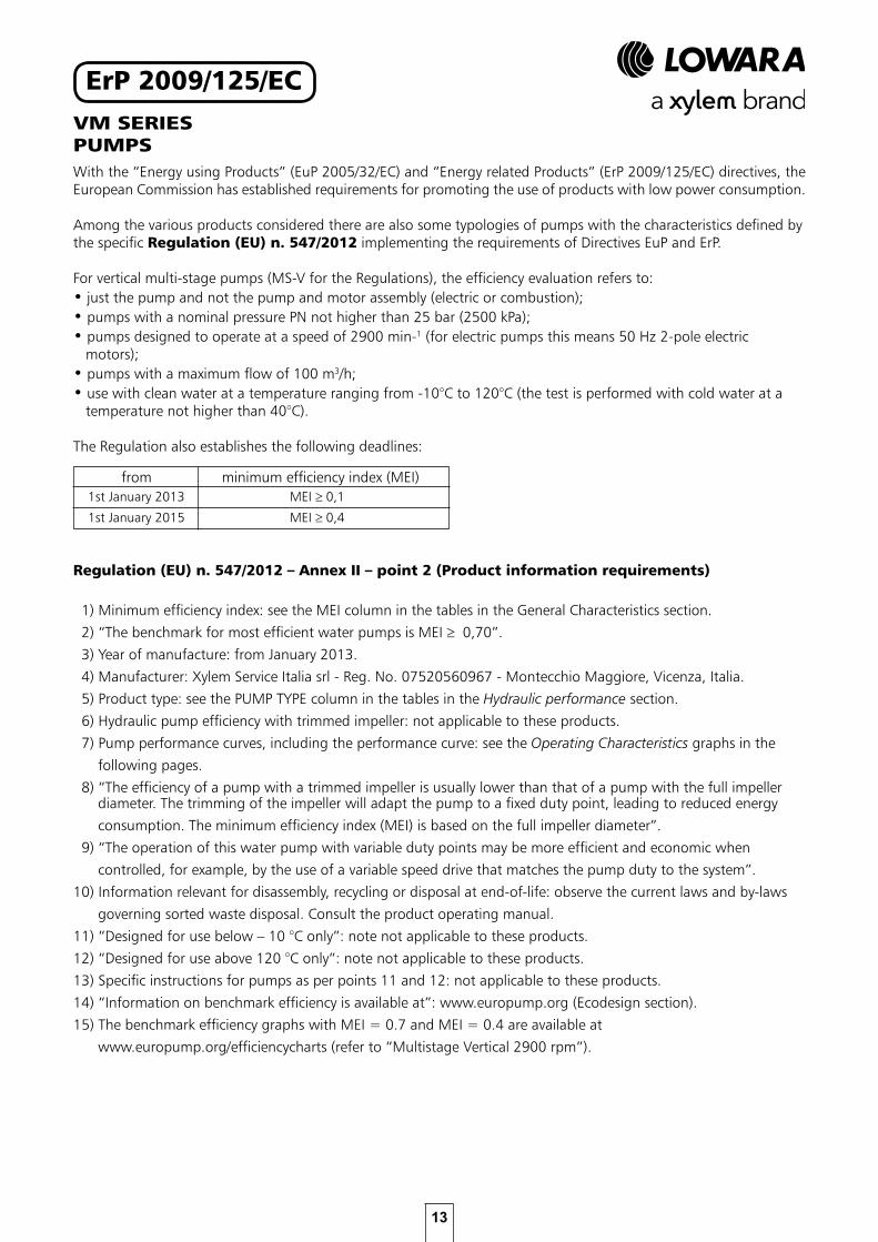
VM SERIESPUMPSWith the “Energy using Products” (EuP 2005/32/EC) and “Energy related Products” (ErP 2009/125/EC) directives, the European Commission has established requirements for promoting the use of products with low power consumption.
Among the various products considered there are also some typologies of pumps with the characteristics defined by the specific Regulation (EU) n. 547/2012 implementing the requirements of Directives EuP and ErP.
For vertical multi-stage pumps (MS-V for the Regulations), the efficiency evaluation refers to:• just the pump and not the pump and motor assembly (electric or combustion);• pumps with a nominal pressure PN not higher than 25 bar (2500 kPa);• pumps designed to operate at a speed of 2900 min-1 (for electric pumps this means 50 Hz 2-pole electric motors); • pumps with a maximum flow of 100 m3/h;• use with clean water at a temperature ranging from -10°C to 120°C (the test is performed with cold water at a temperature not higher than 40°C).
The Regulation also establishes the following deadlines:
Regulation (EU) n. 547/2012 – Annex II – point 2 (Product information requirements)
1) Minimum efficiency index: see the MEI column in the tables in the General Characteristics section.
2) “The benchmark for most efficient water pumps is MEI ≥ 0,70”.
3) Year of manufacture: from January 2013.
4) Manufacturer: Xylem Service Italia srl - Reg. No. 07520560967 - Montecchio Maggiore, Vicenza, Italia.
5) Product type: see the PUMP TYPE column in the tables in the Hydraulic performance section.
6) Hydraulic pump efficiency with trimmed impeller: not applicable to these products.
7) Pump performance curves, including the performance curve: see the Operating Characteristics graphs in the
following pages.
8) “The efficiency of a pump with a trimmed impeller is usually lower than that of a pump with the full impeller diameter. The trimming of the impeller will adapt the pump to a fixed duty point, leading to reduced energy
consumption. The minimum efficiency index (MEI) is based on the full impeller diameter”.
9) “The operation of this water pump with variable duty points may be more efficient and economic when
controlled, for example, by the use of a variable speed drive that matches the pump duty to the system”.
10) Information relevant for disassembly, recycling or disposal at end-of-life: observe the current laws and by-laws
governing sorted waste disposal. Consult the product operating manual.
11) “Designed for use below – 10 °C only”: note not applicable to these products.
12) “Designed for use above 120 °C only”: note not applicable to these products.
13) Specific instructions for pumps as per points 11 and 12: not applicable to these products.
14) “Information on benchmark efficiency is available at”: www.europump.org (Ecodesign section).
15) The benchmark efficiency graphs with MEI = 0.7 and MEI = 0.4 are available at
www.europump.org/efficiencycharts (refer to “Multistage Vertical 2900 rpm”).
from minimum efficiency index (MEI)1st January 2013 MEI ≥ 0,1
MEI ≥ 0,4 1st January 2015
ErP 2009/125/EC

14
VM..P SERIESHYDRAULIC PERFORMANCE RANGE AT 50 Hz, 2 POLES
Q [m3/h]0,6 0,7 0,8 2 3 4 5 6 7 81 10
H [m
]
6
7
8
9
20
25
30
40
50
60
70
80
90
10
100Q [US gpm]4 6 8 20 40 6010
H [f
t]
20
30
40
50
60
70
80
90
200
300
100
Q [Imp gpm]4 6 8 20 4010
Q [l/min]20 40 60 80 20010 100 0648
9_A_
CH
2900 [rpm] ISO 9906:2012 - Grade 3BVM..P
1VM..P1VM..P 3VM..P5VM..P 10VM..P10VM..P5VM..P
3VM..P

15
VM..P SERIESHYDRAULIC PERFORMANCE TABLE AT 50 Hz, 2 POLESTABELLA DI PRESTAZIONI IDRAULICHE SERIE 1, 3, 5, 10 VM..P 2p 50 Hz
PUMP TYPE l/min 0 11,7 16,0 21,0 26,0 31,0 36,0 40,0
VM..P PN TYPE * P1 220-240 V 380-415 V m3/h 0 0,7 1,0 1,3 1,6 1,9 2,2 2,4
kW kW A A1VM03 0,50 SM63HM../1055 0,55 2,60 - 33,3 30,6 29,2 27,3 25,0 22,4 19,3 16,71VM04 0,50 SM63HM../1055 0,63 2,85 - 43,8 39,9 37,9 35,2 32,1 28,5 24,5 21,01VM05 0,50 SM63HM../1055 0,72 3,15 - 53,9 48,7 46,1 42,6 38,6 34,0 28,9 24,51VM06 0,75 SM71HM../1075 0,91 4,25 - 66,5 60,9 58,0 54,1 49,5 44,1 38,0 32,81VM07 0,75 SM71HM../1075 1,01 4,58 - 76,9 70,1 66,6 61,9 56,4 50,1 42,9 36,81VM08 0,95 SM71HM../1095 1,17 5,18 - 88,3 80,5 76,4 71,1 64,8 57,6 49,4 42,51VM02 0,30 SM63HM../303 0,34 1,87 1,08 22,5 20,7 19,7 18,4 16,9 15,1 13,1 11,31VM03 0,30 SM63HM../303 0,46 1,94 1,12 32,6 29,6 28,1 26,1 23,7 21,0 17,9 15,41VM04 0,40 SM63HM../304 0,56 2,32 1,34 43,9 39,9 37,9 35,2 32,1 28,4 24,4 20,91VM05 0,50 SM63HM../305 0,67 2,61 1,51 54,2 49,0 46,3 42,9 38,9 34,4 29,3 25,01VM06 0,75 SM80HM../307 E3 0,80 2,75 1,59 68,5 63,6 60,9 57,2 52,7 47,5 41,5 36,21VM07 0,75 SM80HM../307 E3 0,92 2,97 1,71 79,5 73,6 70,4 66,0 60,7 54,6 47,6 41,51VM08 1,1 SM80HM../311 E3 1,05 3,68 2,12 91,6 85,2 81,7 76,8 70,9 63,9 55,9 48,9
PUMP TYPE l/min 0 20,0 28,0 36,0 44,0 52,0 60,0 70,0
VM..P PN TYPE * P1 220-240 V 380-415 V m3/h 0 1,2 1,7 2,2 2,6 3,1 3,6 4,2
kW kW A A3VM02 0,50 SM63HM../1055 0,53 2,55 - 23,6 21,5 20,4 18,9 17,1 15,0 12,8 9,63VM03 0,50 SM63HM../1055 0,64 2,87 - 34,4 31,2 29,5 27,2 24,6 21,7 18,4 14,03VM04 0,50 SM63HM../1055 0,76 3,29 - 45,0 40,3 37,7 34,5 30,9 26,8 22,5 16,63VM05 0,75 SM71HM../1075 0,99 4,51 - 57,8 52,5 49,6 45,9 41,5 36,5 31,1 23,73VM06 0,95 SM71HM../1095 1,18 5,22 - 69,4 63,1 59,4 54,9 49,6 43,7 37,2 28,33VM07 0,95 SM71HM../1095 1,31 5,68 - 80,3 72,3 67,9 62,5 56,2 49,2 41,6 31,23VM08 1,1 SM80HM../1115 1,48 6,59 - 93,0 84,6 79,9 73,9 66,8 58,9 50,2 38,33VM02 0,30 SM63HM../303 0,43 1,92 1,11 23,2 20,9 19,6 18,1 16,2 14,1 11,9 8,73VM03 0,40 SM63HM../304 0,57 2,32 1,34 34,5 31,3 29,4 27,2 24,5 21,6 18,4 13,93VM04 0,50 SM63HM../305 0,71 2,67 1,54 45,3 40,6 38,0 34,9 31,3 27,3 23,0 17,13VM05 0,75 SM80HM../307 E3 0,90 2,93 1,69 59,5 55,0 52,4 49,0 44,8 39,9 34,5 27,13VM06 1,1 SM80HM../311 E3 1,08 3,71 2,14 71,8 66,7 63,7 59,7 54,7 48,9 42,5 33,53VM07 1,1 SM80HM../311 E3 1,24 4,02 2,32 83,5 77,3 73,7 68,9 63,1 56,3 48,8 38,33VM08 1,5 SM80HM../315 E3 1,41 4,83 2,79 95,8 88,9 84,9 79,5 72,9 65,2 56,6 44,6
PUMP TYPE l/min 0 40,0 53,0 66,0 79,0 92,0 105 120
VM..P PN TYPE * P1 220-240 V 380-415 V m3/h 0 2,4 3,2 4,0 4,7 5,5 6,3 7,2
kW kW A A5VM02 0,50 SM63HM../1055 0,61 2,76 - 23,9 20,4 18,9 17,4 15,5 13,3 10,6 6,65VM03 0,50 SM63HM../1055 0,78 3,36 - 35,0 28,7 26,5 24,2 21,5 18,2 14,0 8,05VM04 0,75 SM71HM../1075 1,06 4,75 - 47,6 39,8 37,1 34,3 30,8 26,4 20,9 12,95VM05 0,95 SM71HM../1095 1,29 5,64 - 59,5 49,4 46,0 42,4 38,0 32,5 25,6 15,65VM06 1,1 SM80HM../1115 1,51 6,76 - 72,1 60,5 56,6 52,3 47,2 40,6 32,3 20,45VM07 1,5 SM80HM../1155 1,81 7,97 - 84,6 72,1 67,8 63,0 57,2 49,7 40,1 26,15VM08 1,5 SM80HM../1155 2,00 8,92 - 96,3 81,4 76,2 70,6 63,7 55,1 44,0 28,15VM02 0,40 SM63HM../304 0,53 2,29 1,32 24,1 20,4 18,9 17,3 15,5 13,3 10,5 6,65VM03 0,50 SM63HM../305 0,73 2,69 1,55 35,3 28,9 26,8 24,5 21,9 18,6 14,4 8,45VM04 1,1 SM80HM../311 E3 1,00 3,57 2,06 49,3 43,0 40,7 38,2 35,1 30,9 25,6 17,65VM05 1,1 SM80HM../311 E3 1,22 3,99 2,30 61,4 53,2 50,3 47,1 43,1 37,9 31,1 21,15VM06 1,5 SM80HM../315 E3 1,45 4,92 2,84 73,8 64,1 60,7 56,9 52,1 45,9 37,8 25,85VM07 1,5 SM80HM../315 E3 1,67 5,35 3,09 85,8 74,2 70,1 65,6 60,0 52,7 43,2 29,25VM08 2,2 PLM90HM../322 E3 1,94 6,77 3,91 98,6 85,9 81,4 76,3 70,0 61,8 51,0 35,0
PUMP TYPE l/min 0 83,3 108 133 158 183 208 233
VM..P PN TYPE * P1 220-240 V 380-415 V m3/h 0 5,0 6,5 8,0 9,5 11,0 12,5 14,0
kW kW A A10VM02 1,1 SM80HM../1115 1,33 6,05 - 30,3 26,4 24,7 22,9 20,8 18,3 15,2 11,610VM03 1,5 SM80HM../1155 1,87 8,27 - 45,6 40,1 37,8 35,3 32,4 28,9 24,7 19,610VM04 2,2 PLM90HM../1225 2,38 10,8 - 61,1 54,2 51,2 47,9 44,1 39,6 33,9 27,110VM05 2,2 PLM90HM../1225 2,84 12,7 - 75,9 66,4 62,5 58,2 53,3 47,5 40,4 31,810VM02 1,1 SM80HM../311 E3 1,22 4,00 2,31 30,8 27,3 25,8 24,0 22,0 19,5 16,5 13,010VM03 1,5 SM80HM../315 E3 1,75 5,48 3,17 46,2 41,4 39,2 36,8 34,0 30,7 26,5 21,410VM04 2,2 PLM90HM../322 E3 2,33 7,54 4,35 61,8 55,4 52,6 49,4 45,8 41,3 35,8 29,010VM05 3 PLM90HM../330 E3 2,91 10,0 5,80 77,3 69,5 66,0 62,1 57,5 51,9 45,0 36,510VM06 3 PLM90HM../330 E3 3,44 11,1 6,41 92,5 82,6 78,3 73,5 67,9 61,1 52,8 42,6
Hydraulic performances in compliance with ISO 9906:2012 - Grade 3B (ex ISO 9906:1999 - Annex A) 1-10vm-p-2p50-en_a_th
* Maximum value in specified range: P1 = input power; I = input current.
1 ~
H = TOTAL HEAD IN METRES OF COLUMN OF WATER
3 ~
1 ~
VERS
ION
VERS
ION
* IMOTOR
3 ~
H = TOTAL HEAD IN METRES OF COLUMN OF WATER
1 ~
Q = DELIVERY
VERS
ION Q = DELIVERY
H = TOTAL HEAD IN METRES OF COLUMN OF WATER
Q = DELIVERYELECTRIC PUMP* I
ELECTRIC PUMP
* I
MOTOR ELECTRIC PUMP* I
Q = DELIVERY
3 ~
H = TOTAL HEAD IN METRES OF COLUMN OF WATER
VERS
ION MOTOR ELECTRIC PUMP
MOTOR
1 ~
3 ~

16
1VM..P SERIES DIMENSIONS AND WEIGHTS AT 50 HZ, 2 POLES
DIMENSIONI E PESI SERIE 1VM 2 poli 50 Hz
PN WEIGHT
kW SIZE D M L bar kg
1VM03 0,50 63 120 111 379 10 12
1VM04 0,50 63 120 111 399 10 13
1VM05 0,50 63 120 111 419 10 13
1VM06 0,75 71 140 121 453 10 15
1VM07 0,75 71 140 121 473 10 16
1VM08 0,95 71 140 130 493 10 17
1VM02 0,30 63 120 111 379 10 11
1VM03 0,30 63 120 111 379 10 11
1VM04 0,40 63 120 111 399 10 12
1VM05 0,50 63 120 111 419 10 13
1VM06 0,75 80 155 129 497 10 18
1VM07 0,75 80 155 129 517 10 19
1VM08 1,1 80 155 129 537 10 20
1vm-2p50-en_a_td
VERSION
SINGLE-PHASE
MOTOR DIMENSIONS (mm)
THREE-PHASE
PUMP TYPE
DIMENSIONS AND WEIGHTS, OPERATING CHARACTERISTICS AT 50 HZ, 2 POLES

17
1VM..P SERIESOPERATING CHARACTERISTICS AT 50 Hz, 2 POLES
These performances are valid for liquids with density ρ = 1 Kg/dm3 and kinematic viscosity ν = 1 mm2/sec.
P p [k
W]
0,0
0,1
0,2
[%
]
20
30
40
0,0 0,5 1,0 1,5 2,0 2,5
NPS
H [m
]
0
2
4
6
0 10 20 30 40
NPS
H [f
t]
0
10
H [m
]
0
20
40
60
80
1000 2 4 6 8 10
H [f
t]
0
50
100
150
200
250
300
0 2 4 6 8
0648
5_A_
CH
ISO 9906:2012 - Grade 3B
Q [US gpm]
Q [Imp gpm]
Q [l/min]
Q [m3/h]
2900 [rpm]
kW/stage
1VM..P
02
03
04
05
06
1~
3~08
07

18
3VM..P SERIES DIMENSIONS AND WEIGHTS AT 50 HZ, 2 POLES
DIMENSIONI E PESI SERIE 3VM 2 poli 50 Hz
PN WEIGHT
kW SIZE D M L bar kg
3VM02 0,50 63 120 111 379 10 12
3VM03 0,50 63 120 111 379 10 12
3VM04 0,50 63 120 111 399 10 13
3VM05 0,75 71 140 121 433 10 15
3VM06 0,95 71 140 130 453 10 16
3VM07 0,95 71 140 130 473 10 17
3VM08 1,1 80 155 137 537 10 20
3VM02 0,30 63 120 111 379 10 11
3VM03 0,40 63 120 111 379 10 12
3VM04 0,50 63 120 111 399 10 13
3VM05 0,75 80 155 129 477 10 18
3VM06 1,1 80 155 129 497 10 19
3VM07 1,1 80 155 129 517 10 20
3VM08 1,5 80 155 129 537 10 21
3vm-2p50-en_a_td
PUMP TYPE VERSION
THREE-PHASE
SINGLE-PHASE
MOTOR DIMENSIONS (mm)

19
3VM..P SERIESOPERATING CHARACTERISTICS AT 50 Hz, 2 POLES
These performances are valid for liquids with density ρ = 1 Kg/dm3 and kinematic viscosity ν = 1 mm2/sec.
P p [k
W]
0,0
0,2
0,4
[%
]
30
40
50
0 1 2 3 4 5
NPS
H [m
]
0
4
8
0 20 40 60 80
NPS
H [f
t]
0
10
20
H [m
]
0
20
40
60
80
1000 5 10 15 20
H [f
t]
0
50
100
150
200
250
300
0 5 10 15
0648
6_A_
CH
ISO 9906:2012 - Grade 3B
Q [US gpm]
Q [Imp gpm]
Q [l/min]
Q [m3/h]
2900 [rpm]
kW/stage
3VM..P
02
03
04
05
06
1~
3~
08
07

20
5VM..P SERIES DIMENSIONS AND WEIGHTS AT 50 HZ, 2 POLES
DIMENSIONI E PESI SERIE 5VM 2 poli 50 Hz
PN WEIGHT
kW SIZE D M L bar kg
5VM02 0,50 63 120 111 379 10 12
5VM03 0,50 63 120 111 379 10 12
5VM04 0,75 71 140 121 413 10 15
5VM05 0,95 71 140 130 433 10 16
5VM06 1,1 80 155 137 497 10 19
5VM07 1,5 80 155 137 517 10 21
5VM08 1,5 80 155 137 537 10 21
5VM02 0,40 63 120 111 379 10 12
5VM03 0,50 63 120 111 379 10 12
5VM04 1,1 80 155 129 457 10 19
5VM05 1,1 80 155 129 477 10 19
5VM06 1,5 80 155 129 497 10 20
5VM07 1,5 80 155 129 517 10 21
5VM08 2,2 90 174 134 593 10 26
5vm-2p50-en_a_td
PUMP TYPE VERSION
THREE-PHASE
SINGLE-PHASE
MOTOR DIMENSIONS (mm)

21
5VM..P SERIESOPERATING CHARACTERISTICS AT 50 Hz, 2 POLES
These performances are valid for liquids with density ρ = 1 Kg/dm3 and kinematic viscosity ν = 1 mm2/sec.
P p [k
W]
0,1
0,2
0,3
[%
]
20
40
60
0 2 4 6 8
NPS
H [m
]
0
3
6
0 20 40 60 80 100 120
NPS
H [f
t]
0
10
H [m
]
0
20
40
60
80
1000 10 20 30
H [f
t]
0
50
100
150
200
250
300
0 5 10 15 20 25
0648
7_A_
CH
ISO 9906:2012 - Grade 3B
Q [US gpm]
Q [Imp gpm]
Q [l/min]
Q [m3/h]
2900 [rpm]
kW/stage
5VM..P
02
03
04
05
06
1~
3~
08
07

22
10VM..P SERIES DIMENSIONS AND WEIGHTS AT 50 HZ, 2 POLES
DIMENSIONI E PESI SERIE 10VM 2 poli 50 Hz
PN WEIGHT
kW SIZE D M L bar kg
10VM02 1,1 80 155 137 501 10 23
10VM03 1,5 80 155 137 533 10 25
10VM04 2,2 90 174 159 621 10 34
10VM05 2,2 90 174 159 653 10 35
10VM02 1,1 80 155 129 501 10 23
10VM03 1,5 80 155 129 533 10 25
10VM04 2,2 90 174 134 621 10 31
10VM05 3 90 174 134 653 10 35
10VM06 3 90 174 134 685 10 36
10vm-2p50-en_a_td
PUMP TYPE VERSION
THREE-PHASE
SINGLE-PHASE
MOTOR DIMENSIONS (mm)
23
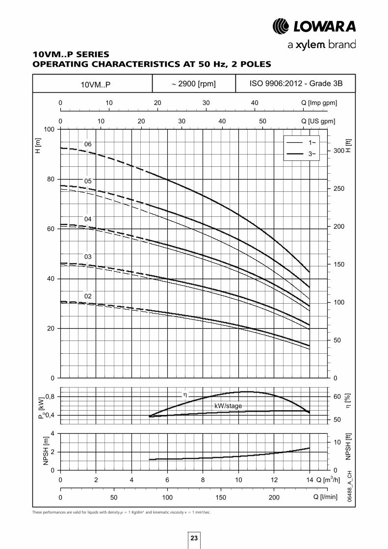
10VM..P SERIESOPERATING CHARACTERISTICS AT 50 Hz, 2 POLES
These performances are valid for liquids with density ρ = 1 Kg/dm3 and kinematic viscosity ν = 1 mm2/sec.
P p [k
W]
0,4
0,8
[%
]
50
60
0 2 4 6 8 10 12 14
NPS
H [m
]
0
2
4
0 50 100 150 200 250
NPS
H [f
t]
0
10
H [m
]
0
20
40
60
80
1000 10 20 30 40 50 60
H [f
t]
0
50
100
150
200
250
300
0 10 20 30 40 50
0648
8_A_
CH
ISO 9906:2012 - Grade 3B
Q [US gpm]
Q [Imp gpm]
Q [l/min]
Q [m3/h]
2900 [rpm]
kW/stage
10VM..P
02
04
05
06 1~
3~
03

24

25
VM WITH VARIABLE FREQUENCY DRIVE

26
ECODESIGN DIRECTIVE (ErP)
The Ecodesign directive was put in place in 2011 and introduced minimum requirements for the efficiency of AC motors and pumps. Over the last few years, these requirements have been gradually intensified.
Motors are classified based on their mode of operation. Fixed speed motors are classified according to IEC 60034-30-1 and the minimum acceptable level of efficiency is IE3 since January 2017 for 0.75 to 375 kW rated powers 3 phase motors, according to the Directive 2009/125/EC. Variable speed motors (not covered in IEC 60034-30-1), which are not designed to operate direct on-line, are classified according to the technical specification IEC/TS 60034-30-2. This Technical Specification introduced the “ultra-premium” IE5 efficiency performance, the best efficiency existing level for this kind of motors.
In 2014, with the standard EN 50598, there was a switch in the definition of efficiency class from an individual component approach towards an overall system one; which is the basic point for the “Extended product approach“ (EPA).Taking this concept further, the EN50598-2 introduced IES efficiency classes for frequency converters + motor systems (known as power drive systems-PDS) with power rating from 0.12 kW to 1000kW and from 100V to 1000V.For Power Drive System (PDS) the defined efficiency classes are IES0, IES1, IES2. If a PDS has 20% greater losses than the reference value of IES1 then it is classified as IES0; if it has 20% lower losses than the reference value of IES1 then it is classified as IES2.
With the eSM drive, which powers an IE5 permanent magnet motor, the system surpasses the highest IES class – IES2.
The VM pump series is therefore already ready for the 2020 EU Ecodesign energy efficiency objectives.

27
VMEVERSION WITH DRIVE
AND PERMANENTMAGNET MOTOR
(e-SM DRIVE)
VME VERSION WITH DRIVE AND PERMANENT MAGNET MOTOR (e-SM DRIVE)

28
e-SM System
•Single-phase power supply: 230V +/- 10%, 50/60 Hz
•Three-phase power supply: – from 0,37kW to 1,5kW: 230/400V +/- 10%, 50/60 Hz – 2,2kW: 400V +/- 10%, 50/60 Hz•Power up to 2,2 kW•Protection class IP55•Can be linked up to 3 VM Smart pumps
Pump
•Flow rate: up to 17 m3/h•Head: up to 100 m•Environment temperature: -20°C to + 50°C with no•performance derating•Temperature of pumped liquid: up to + 90°C•Maximum operating pressure 10 bar (PN 10)•The hydraulic performances meet the tolerances
specified in ISO 9906:2012
Motor
•IE5 efficiency level (IEC TS 60034-30-2:2016)•Synchronous electric motor with permanent magnets
(TEFC), closed structure, air-cooled•Insulation class 155 (F)•Overload protection and locked rotor with automatic
reset incorporated
Background and context
In every sector, from construction and industry to agriculture and building services the need for intelligent, compact and high-efficiency pumping systems is constantly growing.That’s why Lowara has developed the VM series: an integrated intelligent pumping system with electronically driven, permanent magnet motor (IE5 efficiency level).The integrated control system, combined with the high performance, power and efficiency from the motor and hydraulics, guarantees impressively low operating costs. You also benefit from flexibility, precision and its ultra-compact size.
SavingsThe electronics and permanent magnet motor are highly efficient and minimize power losses while transferring maximum energy to the hydraulic parts of the pump. The refined control system with integrated microprocessor adjusts the motor speed, matching the required operating point of the pump or system requirements. This reduces demand on electricity according to the required working conditions. This creates economies, especially in systems where pump demand varies over time.
FlexibilityThe compact size, low loss and increased control make the VM Smart series a good choice in applications and systems where fixed speed pumps are commonly used. The VM Smart series is easy to integrate in control and regulation loops thanks to the wide availability of compatible communication protocols, including analog and digital inputs.The pump is supplied with a pressure sensor.
Ease of use and commissioningVM Smart has an intuitive interface that guides the user through the installation, and a practical area to assist with connections. The control system is integrated and no additional external electrical panel is required.
Application sectors
•Water supply systems in residential buildings•Air conditioning•Water treatment plants•Industrial installations
VMEVM SMART SERIES

29
VMEVM SMART SERIES
Integrated intelligence: the electronic control of the motor enables a 20% increase in performance compared to an equivalent fixed speed pump (area highlighted in figure “Integrated Intelligence”).
Adjustment: This is possible both at constant pressure and according to the characteristic curve of the system, based on the customer’s preferences. Another option is according to an external signal or at a preset speed.
1
2
6
7
5
9
8
3 4
ESM_M0021_A_sc
Integrated intelligence
Control for constant pressure
Control to match a system curve
Intuitive and simple interface: you can control the unit from just three buttons, with an easy to read display for parameters and alarms, designed for complete control of system operation.
B Communication LEDC Power on LEDD Unit of measure LEDE Speed LED barF Status LEDG Numeric displayH Decrease keyI On/off and menu keyJ Increase key
Integrated intelligence
Control for constant pressure
Control to match a system curve
VM Smart series is equipped with an intelligent control that optimizes hydraulic performance while minimizing waste.

30
VME SERIESSINGLE PHASE TERMINAL BLOCK
MorsT-en_a_sc
MorsM-en_a_sc
THREE-PHASE TERMINAL BLOCK
ESM
_MO
R_B
_SC
1 2 3
4 5 6 87 9 10 11 12 13 14 15 16 17 18 19 20
ESM
_MO
R_B
_SC
25 24 23 22 21 20 19 18 17 16 15 14 13 12 11 10 9 8 7 6 5 4 3 2 1

31
To exploit to the maximum potential of Smart Pumps it’s important to properly read working curves:
B Pump model
C Maximum speed curve: equal to 3600 rpm
D Minimum speed curve: it refers to the minimum rpm level the motor can work at, it’s calculated depending on the model of pump maximizing for each one the working area and allowing the highest system flexibility.
E The area with dotted lines is where he pump can only operate intermittently for short period s of time.
F Each intermediate curve between max and min speed shows the percentage of load the pump+motor+drive system is working at; it’s easy to read also from the LED speed bar on the HMI keypad: at 90% there will be 9 led, at 80% there will be 8 and so on.
Example: at 60% there will be 6 lit led’s
1VME02P03
0 2 4 6 8 10
0.0 0.1 0.2 0.3 0.4 0.5 0.6 0.7 0.8 0.9
Q [Imp gpm]
Q [l/s]
max
90%
40%
30%
20%
50%
10%
60%
80%
70%
min
0 2 4 6 8 10 12 14
0
20
40
60
80
100
0
5
10
15
20
25
30
35Q [US gpm]
H [f
t]
H[m
]
max
0
5
10
15
20
25
0
2
4
6
8N
PSH
[ft]
NPS
H[m
]
0
10
20
30
40
50
0.0
0.1
0.2
0.3
0.4
0.5
0.0 0.5 1.0 1.5 2.0 2.5 3.0
η[%
]
P1gr
[kW
]
Q [m3/h]
A03
51_A
_CH
ηp
ηgr
1
4
3
5
7
8
10
11
9
2
6
12
VMEHOW TO READ SMART PUMP SERIES CURVES
G The part load percentage is calculated depending on maximum speed (max, 100%) and minimum speed (min, equal to 0%, which is the minimum part load step, below it the drive stays powered up but cannot work).
H NPSH: is the net positive suction head of pump+motor+drive system working at maximum speed.
I P1gr is the power absorption in kW of pump+motor+drive system working at maximum speed. J Load control: the Smart Pump controls and limits power consumption at high flow/low head, in this way the motor stays protected from overload and ensure a longer life of pump+motor+drive system.
K ηgr is the efficiency of pump+motor+drive system working at maximum speed.
L ηp is the efficiency of the hydraulic part, working at maximum speed.
M Working point: it’s important to make sure the pump is working at the best working point, the one at highest efficiency.It’s easy to find it: it’s the highest point of the hp pump efficiency curve; once you found it, you can learn also flow values from x-axis called Q and head values from y-axis called H which allow the system to work at the best working point.

32
VME SERIES - SINGLE-PHASE VERSIONHYDRAULIC PERFORMANCE TABLE
1-10vme-esm-2p50-en_a_th
ELETTRICAL DATA TABLE
ϕϕϕϕ
ηηηη
Constructio
n
In the range 3000-3600 rpm the nominal motor power is guaranteed. Above 3600 rpm it isn’t possible work and the motor is automatically limited; below 3000 rpm it works partially load.

33
VME SERIES - THREE-PHASE VERSIONHYDRAULIC PERFORMANCE TABLE
1-10vme-esmT-2p50-en_a_th
ELETTRICAL DATA TABLE
In the range 3000-3600 rpm the nominal motor power is guaranteed. Above 3600 rpm it isn’t possible work and the motor is automatically limited; below 3000 rpm it works partially load.
ϕϕϕϕ
ηηηη

34
1, 3, 5VME SERIES - SINGLE-PHASE VERSIONDIMENSIONS AND WEIGHTS
1-5vme-esm-2p50-en_a_td

35
1, 3, 5VME SERIES - THREE-PHASE VERSIONDIMENSIONS AND WEIGHTS
1-5V
ME-
T-eS
M_A
_DD
1-3-5VME
G 3/8
G 1/4
Ø132
180 210
N.4xØ13
100
211
L
D D
150
190
50
20
157
125 125
277
250
1-5vme-esm-2p50T-en_a_td

36
1VME SERIES OPERATING CHARACTERISTICS
The performances are valid for liquid with density ρ = 1 Kg/dm3 and kinematic viscosity ν = 1 mm2/sec.
1VME02P03
0 2 4 6 8 10 12
0.0 0.1 0.2 0.3 0.4 0.5 0.6 0.7 0.8 0.9
Q [Imp gpm]
Q [l/s]
max
90%
40%
30%
20%
50%
10%
60%
80%
70%
min
0 2 4 6 8 10 12 14
0
20
40
60
80
100
0
5
10
15
20
25
30
35Q [US gpm]
H [ft
]
H[m
]
max
0
5
10
15
20
25
0
2
4
6
8
NPS
H[ft]
NPS
H[m
]
0
10
20
30
40
50
0.0
0.1
0.2
0.3
0.4
0.5
0.0 0.5 1.0 1.5 2.0 2.5 3.0 3.5
[%
]
P1gr
[kW
]
Q [m3/h]
A035
1_B_
CH
ηp
ηgr

37
1VME SERIES OPERATING CHARACTERISTICS
The performances are valid for liquid with density ρ = 1 Kg/dm3 and kinematic viscosity ν = 1 mm2/sec.
1VME04P05
0 2 4 6 8 10 12
0.0 0.1 0.2 0.3 0.4 0.5 0.6 0.7 0.8 0.9
Q [Imp gpm]
Q [l/s]
max
90%
40%
30%
20%
50%
10%
60%
80%
70%
min
0 2 4 6 8 10 12 14
0
20
40
60
80
100
120
140
160
180
0
10
20
30
40
50
60Q [US gpm]
H [ft
]
H[m
]
max
0
5
10
15
20
25
0
2
4
6
8
NPS
H[ft]
NPS
H[m
]
0
10
20
30
40
0.0
0.2
0.4
0.6
0.8
0.0 0.5 1.0 1.5 2.0 2.5 3.0 3.5
[%
]
P1gr
[kW
]
Q [m3/h]
A035
2_B_
CH
ηp
ηgr

38
1VME SERIES OPERATING CHARACTERISTICS
The performances are valid for liquid with density ρ = 1 Kg/dm3 and kinematic viscosity ν = 1 mm2/sec.
1VME05P07
0 2 4 6 8 10 12
0.0 0.1 0.2 0.3 0.4 0.5 0.6 0.7 0.8 0.9
Q [Imp gpm]
Q [l/s]
max
90%
40%
30%
20%
50%
10%
60%
80%
70%
min
0 2 4 6 8 10 12 14
0
50
100
150
200
250
0
10
20
30
40
50
60
70
80
90Q [US gpm]
H [ft
]
H[m
]
max
0
5
10
15
20
25
0
2
4
6
8
NPS
H[ft]
NPS
H[m
]
0
10
20
30
40
50
0.0
0.2
0.4
0.6
0.8
1.0
0.0 0.5 1.0 1.5 2.0 2.5 3.0 3.5
[%
]
P1gr
[kW
]
Q [m3/h]
A035
3_B_
CH
ηp
ηgr

39
1VME SERIES OPERATING CHARACTERISTICS
The performances are valid for liquid with density ρ = 1 Kg/dm3 and kinematic viscosity ν = 1 mm2/sec.
1VME06P11
0 2 4 6 8 10 12
0.0 0.1 0.2 0.3 0.4 0.5 0.6 0.7 0.8 0.9
Q [Imp gpm]
Q [l/s]
max
90%
40%
30%
20%
50%
10%
60%
80%
70%
min
0 2 4 6 8 10 12 14
0
50
100
150
200
250
300
0
10
20
30
40
50
60
70
80
90
100Q [US gpm]
H [ft
]
H[m
]
max
0
5
10
15
20
25
0
2
4
6
8
NPS
H[ft]
NPS
H[m
]
0
20
40
60
0.0
0.5
1.0
1.5
0.0 0.5 1.0 1.5 2.0 2.5 3.0 3.5
[%
]
P1gr
[kW
]
Q [m3/h]
A035
4_B_
CH
ηp
ηgr

40
3VME SERIES OPERATING CHARACTERISTICS
The performances are valid for liquid with density ρ = 1 Kg/dm3 and kinematic viscosity ν = 1 mm2/sec.
3VME02P03
0 5 10 15 20
0.0 0.2 0.4 0.6 0.8 1.0 1.2 1.4 1.6
Q [Imp gpm]
Q [l/s]
max
90%
40%
30%
20%
50%
10%
60%
80%
70%
min
0 5 10 15 20 25
0
20
40
60
80
100
120
0
10
20
30
40Q [US gpm]
H [ft
]
H[m
]
max
0
10
20
30
0
4
8
12
NPS
H[ft]
NPS
H[m
]
0
20
40
60
0.0
0.2
0.4
0.6
0 1 2 3 4 5 6
[%
]
P1gr
[kW
]
Q [m3/h]
A035
9_B_
CH
ηp
ηgr

41
3VME SERIES OPERATING CHARACTERISTICS
The performances are valid for liquid with density ρ = 1 Kg/dm3 and kinematic viscosity ν = 1 mm2/sec.
3VME03P05
0 5 10 15 20
0.0 0.2 0.4 0.6 0.8 1.0 1.2 1.4 1.6
Q [Imp gpm]
Q [l/s]
max
90%
40%
30%
20%
50%
10%
60%
80%
70%
min
0 5 10 15 20 25
0
20
40
60
80
100
120
140
160
180
0
10
20
30
40
50
60Q [US gpm]
H [ft
]
H[m
]
max
0
10
20
30
0
4
8
12
NPS
H[ft]
NPS
H[m
]
0
20
40
60
80
0.0
0.2
0.4
0.6
0.8
0 1 2 3 4 5 6
[%
]
P1gr
[kW
]
Q [m3/h]
A036
0_B_
CH
ηp
ηgr

42
3VME SERIES OPERATING CHARACTERISTICS
The performances are valid for liquid with density ρ = 1 Kg/dm3 and kinematic viscosity ν = 1 mm2/sec.
3VME04P07
0 5 10 15 20
0.0 0.2 0.4 0.6 0.8 1.0 1.2 1.4 1.6
Q [Imp gpm]
Q [l/s]
max
90%
40%
30%
20%
50%
10%
60%
80%
70%
min
0 5 10 15 20 25
0
50
100
150
200
250
0
10
20
30
40
50
60
70
80Q [US gpm]
H [ft
]
H[m
]
max
0
10
20
30
0
4
8
12
NPS
H[ft]
NPS
H[m
]
0
10
20
30
40
50
0.0
0.2
0.4
0.6
0.8
1.0
0 1 2 3 4 5 6
[%
]
P1gr
[kW
]
Q [m3/h]
A036
1_B_
CH
ηp
ηgr

43
3VME SERIES OPERATING CHARACTERISTICS
The performances are valid for liquid with density ρ = 1 Kg/dm3 and kinematic viscosity ν = 1 mm2/sec.
3VME05P11
0 5 10 15 20
0.0 0.2 0.4 0.6 0.8 1.0 1.2 1.4 1.6
Q [Imp gpm]
Q [l/s]
max
90%
40%
30%
20%
50%
10%
60%
80%
70%
min
0 5 10 15 20 25
0
50
100
150
200
250
0
10
20
30
40
50
60
70
80
90Q [US gpm]
H [ft
]
H[m
]
max
0
10
20
30
0
4
8
12
NPS
H[ft]
NPS
H[m
]
0
20
40
60
0.0
0.5
1.0
1.5
0 1 2 3 4 5 6
[%
]
P1gr
[kW
]
Q [m3/h]
A036
2_B_
CH
ηp
ηgr

44
3VME SERIES OPERATING CHARACTERISTICS
The performances are valid for liquid with density ρ = 1 Kg/dm3 and kinematic viscosity ν = 1 mm2/sec.
3VME06P15
0 5 10 15 20
0.0 0.2 0.4 0.6 0.8 1.0 1.2 1.4 1.6
Q [Imp gpm]
Q [l/s]
max
90%
40%
30%
20%
50%
10%
60%
80%
70%
min
0 5 10 15 20 25
0
50
100
150
200
250
300
350
0
10
20
30
40
50
60
70
80
90
100
110Q [US gpm]
H [ft
]
H[m
]
max
0
10
20
30
0
4
8
12
NPS
H[ft]
NPS
H[m
]
0
10
20
30
40
50
0.0
0.5
1.0
1.5
2.0
0 1 2 3 4 5 6
[%
]
P1gr
[kW
]
Q [m3/h]
A036
3_B_
CH
ηp
ηgr

45
5VME SERIES OPERATING CHARACTERISTICS
The performances are valid for liquid with density ρ = 1 Kg/dm3 and kinematic viscosity ν = 1 mm2/sec.
5VME02P05
0 5 10 15 20 25 30
0.0 0.5 1.0 1.5 2.0 2.5
Q [Imp gpm]
Q [l/s]
max
90%
40%
30%
20%
50%
10%
60%
80%
70%
min
0 5 10 15 20 25 30 35
0
20
40
60
80
100
120
0
5
10
15
20
25
30
35
40Q [US gpm]
H [ft
]
H[m
]
max
0
5
10
15
20
25
0
2
4
6
8
NPS
H[ft]
NPS
H[m
]
0
20
40
60
0.0
0.2
0.4
0.6
0.8
0 1 2 3 4 5 6 7 8 9
[%
]
P1gr
[kW
]
Q [m3/h]
A036
9_B_
CH
ηp
ηgr

46
5VME SERIES OPERATING CHARACTERISTICS
The performances are valid for liquid with density ρ = 1 Kg/dm3 and kinematic viscosity ν = 1 mm2/sec.
5VME03P07
0 5 10 15 20 25 30
0.0 0.5 1.0 1.5 2.0 2.5
Q [Imp gpm]
Q [l/s]
max
90%
40%
30%
20%
50%
10%
60%
80%
70%
min
0 5 10 15 20 25 30 35
0
20
40
60
80
100
120
140
160
180
0
10
20
30
40
50
60Q [US gpm]
H [ft
]
H[m
]
max
0
5
10
15
20
25
0
2
4
6
8
NPS
H[ft]
NPS
H[m
]
0
20
40
60
80
0.0
0.2
0.4
0.6
0.8
1.0
0 1 2 3 4 5 6 7 8 9
[%
]
P1gr
[kW
]
Q [m3/h]
A037
0_B_
CH
ηp
ηgr

47
5VME SERIES OPERATING CHARACTERISTICS
The performances are valid for liquid with density ρ = 1 Kg/dm3 and kinematic viscosity ν = 1 mm2/sec.
5VME04P11
0 5 10 15 20 25 30
0.0 0.5 1.0 1.5 2.0 2.5
Q [Imp gpm]
Q [l/s]
max
90%
40%
30%
20%
50%
10%
60%
80%
70%
min
0 5 10 15 20 25 30 35
0
50
100
150
200
250
0
10
20
30
40
50
60
70
80Q [US gpm]
H [ft
]
H[m
]
max
0
5
10
15
20
25
0
2
4
6
8
NPS
H[ft]
NPS
H[m
]
0
10
20
30
40
50
60
0.0
0.5
1.0
1.5
0 1 2 3 4 5 6 7 8 9
[%
]
P1gr
[kW
]
Q [m3/h]
A037
1_B_
CH
ηp
ηgr

48
5VME SERIES OPERATING CHARACTERISTICS
The performances are valid for liquid with density ρ = 1 Kg/dm3 and kinematic viscosity ν = 1 mm2/sec.
5VME05P15
0 5 10 15 20 25 30
0.0 0.5 1.0 1.5 2.0 2.5
Q [Imp gpm]
Q [l/s]
max
90%
40%
30%
20%
50%
10%
60%
80%
70%
min
0 5 10 15 20 25 30 35
0
50
100
150
200
250
300
0
10
20
30
40
50
60
70
80
90
100Q [US gpm]
H [ft
]
H[m
]
max
0
5
10
15
20
25
0
2
4
6
8
NPS
H[ft]
NPS
H[m
]
0
20
40
60
80
0.0
0.5
1.0
1.5
2.0
0 1 2 3 4 5 6 7 8 9
[%
]
P1gr
[kW
]
Q [m3/h]
A037
2_B_
CH
ηp
ηgr

49
5VME SERIES OPERATING CHARACTERISTICS
The performances are valid for liquid with density ρ = 1 Kg/dm3 and kinematic viscosity ν = 1 mm2/sec.
5VME06P22
0 5 10 15 20 25 30
0.0 0.5 1.0 1.5 2.0 2.5
Q [Imp gpm]
Q [l/s]
max
90%
40%
30%
20%
50%
10%
60%
80%
70%
min
0 5 10 15 20 25 30 35
0
50
100
150
200
250
300
0
10
20
30
40
50
60
70
80
90
100Q [US gpm]
H [ft
]
H[m
]
max
0
10
20
0
2
4
6
8
NPS
H[ft
]
NPS
H[m
]
0
15
30
45
60
75
0.0
0.5
1.0
1.5
2.0
2.5
0 1 2 3 4 5 6 7 8 9
η[%
]
P1gr
[kW
]
Q [m3/h]
A045
3_A_
CH
ηp
ηgr

50
10VME SERIES - SINGLE-PHASE VERSIONDIMENSIONS AND WEIGHTS
DIMENSIONI E PESI SERIE 10VME 2 poli 50 Hz
PN WEIGHT
kW SIZE D L bar kg
10VME01P07M02 0,75 80 Rp 1 1/2 479 10 19,9
10VME02P11M02 1,1 80 Rp 1 1/2 479 10 21,5
10vme-esm-2p50-en_a_td
PUMP TYPE
VERSIONMOTOR DIMENSIONS (mm)
SINGLE-PHASE

51
10VME SERIES - THREE-PHASE VERSIONDIMENSIONS AND WEIGHTS
10V
ME-
T-eS
M_A
_DD
10VME
G 3/8
G 1/4
Ø132
N.4xØ13
211
130
245215
220180
L
D D
8025
277
125 125250
157

52
10VME SERIES OPERATING CHARACTERISTICS
The performances are valid for liquid with density ρ = 1 Kg/dm3 and kinematic viscosity ν = 1 mm2/sec.
10VME01P07
0 10 20 30 40 50 60
0.0 0.5 1.0 1.5 2.0 2.5 3.0 3.5 4.0 4.5 5.0
Q [Imp gpm]
Q [l/s]
max
90%
40%
30%
20%
50%
10%
60%
80%
70%
min
0 10 20 30 40 50 60 70
0
10
20
30
40
50
60
70
80
0
5
10
15
20
25Q [US gpm]
H [ft
]
H[m
]
max
0
5
10
15
20
25
0
2
4
6
8
NPS
H[ft]
NPS
H[m
]
0
20
40
60
80
0.0
0.2
0.4
0.6
0.8
1.0
0 2 4 6 8 10 12 14 16 18
[%
]
P1gr
[kW
]
Q [m3/h]
A037
8_B_
CH
ηp
ηgr

53
10VME SERIES OPERATING CHARACTERISTICS
The performances are valid for liquid with density ρ = 1 Kg/dm3 and kinematic viscosity ν = 1 mm2/sec.
10VME02P11
0 10 20 30 40 50 60
0.0 0.5 1.0 1.5 2.0 2.5 3.0 3.5 4.0 4.5 5.0
Q [Imp gpm]
Q [l/s]
max
90%
40%
30%
20%
50%
10%
60%
80%
70%
min
0 10 20 30 40 50 60 70
0
20
40
60
80
100
120
0
5
10
15
20
25
30
35
40Q [US gpm]
H [ft
]
H[m
]
max
0
5
10
15
20
25
0
2
4
6
8
NPS
H[ft]
NPS
H[m
]
0
20
40
60
0.0
0.5
1.0
1.5
0 2 4 6 8 10 12 14 16 18
[%
]
P1gr
[kW
]
Q [m3/h]
A037
9_B_
CH
ηp
ηgr

54

55
ACCESSORIES

56
MODEL REF. CODE DESCRIPTION
Ball valve 1" 002676438 1" FF PN38 WITH DRAIN, CHROME PLATED BRASS
1" 002679402 1" FF PN30, CHROME PLATED BRASS
1" 1/4 R02661422 1”1/4 FF PN30, CHROME PLATED BRASS
1" 1/2 R02661427 1”1/2 FF PN30, CHROME PLATED BRASS
2" R02661424 2” FF PN25, CHROME PLATED BRASS
1" 002675155 1" MF PN40, CHROME PLATED BRASS
1" 1/4 R02661318 1"1/4 MF PN30, CHROME PLATED BRASS
1" 1/2 002675369 1"1/2 MF PN25. CHROME PLATED BRASS
2" 002679408 2" MF PN25, CHROME PLATED BRASS
1" 002679403 1" MF WITH UNION JOINT, CHROME PLATED BRASS
1" 1/4 002679404 1"1/4 MF WITH UNION JOINT, CHROME PLATED BRASS
1" 1/2 002676452 1"1/2 MF WITH UNION JOINT, CHROME PLATED BRASS
2" NO CODE 2" MF WITH UNION JOINT, CHROME PLATED BRASS
Non-return valve 1" 002675029 1" MF SUCTION MALE, PN 25, BRASS
1" 1/4 002675036 1"1/4 MF SUCTION MALE, PN 25, BRASS
1" 1/2 002675043 1"1/2 MF SUCTION MALE, PN 25, BRASS
2" 002675032 2" MF SUCTION MALE, PN 40, BRASS
1" 002675300 1" MF SUCTION MALE, PN16, STAINLESS STEEL AISI304
1" 1/4 002675301 1"1/4 MF SUCTION MALE, PN16, STAINLESS STEEL AISI304
1" 1/2 002675302 1"1/2 MF SUCTION MALE, PN16, STAINLESS STEEL AISI304
2" 002675303 2" MF SUCTION MALE, PN16, STAINLESS STEEL AISI304
1" 002675295 1" FF PN32, STAINLESS STEEL AISI316
1" 1/4 002675296 1"1/4 FF PN28, STAINLESS STEEL AISI316
1" 1/2 002675297 1"1/2 FF PN28, STAINLESS STEEL AISI316
2" 002675298 2" FF PN23, STAINLESS STEEL AISI316
Union 3 Pieces MF 1" R02671048 1" MF, GALVANISED STEEL
1" 1/4 R02671050 1"1/4 MF, GALVANISED STEEL
1" 1/2 R02671052 1"1/2 MF, GALVANISED STEEL
2" R02671054 2" MF, GALVANISED STEEL
1" 002672655 1" MF, STAINLESS STEEL AISI 316
1" 1/4 002672656 1"1/4 MF, STAINLESS STEEL AISI 316
1" 1/2 002672657 1"1/2 MF, STAINLESS STEEL AISI 316
2" 002672658 2" MF, STAINLESS STEEL AISI 316
GENYO 1” 109120160 GENYO 8A/F12
109120161 GENYO 8A/F12, WITH ELECTRICAL CABLE
109120170 GENYO 8A/F15
109120171 GENYO 8A/F15 WITH ELECTRICAL CABLE
109120180 GENYO 8A/F22
109120181 GENYO 8A/F22 WITH ELECTRICAL CABLE
109120210 GENYO 16A/R15-30
109120211 GENYO 16A/R15-30 WITH ELECTRICAL CABLE
Diaphragm tank 8 lt 106110550 8 LITRES-8 BAR, 1" CONNECTION, FLANGE IN GALVANISED STEEL
24 lt 106110560 24 LITRES-8 BAR, 1" CONNECTION, FLANGE IN GALVANISED STEEL
24 lt 106111180 24 LITRES-10 BAR, 1" CONNECTION, FLANGE IN GALVANISED STEEL
24 lt 106111190 24 LITRES-16 BAR, 1" CONNECTION, FLANGE IN GALVANISED STEEL
18 lt 106227110 18 LITRES-10 BAR, 1" CONNECTION, FLANGE IN STAINLESS STEEL AISI304
24 lt 106110660 24 LITRES-10 BAR, 1" CONNECTION, FLANGE IN STAINLESS STEEL AISI304
24 lt 106110630 24 LITRES-16 BAR, 1" CONNECTION, FLANGE IN STAINLESS STEEL AISI304
ACCESSORIES

57
MODEL REF. CODE DESCRIPTION
Flexible Hose 1" 002542016 1" MF, L=170MM PN16, REINFORCING BRADING IN GALVANISED STEEL
002542001 1" MF, L=180MM PN16, REINFORCING BRADING IN GALVANISED STEEL
002542002 1" MF, L=230MM PN16, REINFORCING BRADING IN GALVANISED STEEL
002542018 1" MF, L=360MM PN16, REINFORCING BRADING IN GALVANISED STEEL
002542012 1" MF, L=400MM PN16, REINFORCING BRADING IN GALVANISED STEEL
002542007 1" MF, L=430MM PN16, REINFORCING BRADING IN GALVANISED STEEL
002542003 1" MF, L=450MM PN16, REINFORCING BRADING IN GALVANISED STEEL
002542010 1" MF, L=500MM PN16, REINFORCING BRADING IN GALVANISED STEEL
002542000 1" MF L=550MM PN16, REINFORCING BRADING IN GALVANISED STEEL
002542014 1" MF L=600MM PN16, REINFORCING BRADING IN GALVANISED STEEL
002542004 1" MF, L=700MM PN16, REINFORCING BRADING IN GALVANISED STEEL
002542019 1" MF, L=800MM PN16, REINFORCING BRADING IN GALVANISED STEEL
002542022 1" MF, L=1000MM PN16, REINFORCING BRADING IN GALVANISED STEEL
1" 1/4 002542040 1"1/4 MF L=700MM PN16, REINFORCING BRADING IN GALVANISED STEEL
002542041 1"1/4 MF L=800MM PN16, REINFORCING BRADING IN GALVANISED STEEL
002542042 1"1/4 MF L=900MM PN16, REINFORCING BRADING IN GALVANISED STEEL
002542044 1"1/4 MF L=1000MM PN16, REINFORCING BRADING IN GALVANISED STEEL
1"1/2 002542050 1"1/2 MF L=500MM PN16, REINFORCING BRADING IN GALVANISED STEEL
002542054 1"1/2 MF L=800MM PN16, REINFORCING BRADING IN GALVANISED STEEL
2" 002542069 2" MF L=500MM PN16, REINFORCING BRADING IN GALVANISED STEEL
002542070 2" MF L=600MM PN16, REINFORCING BRADING IN GALVANISED STEEL
1" + Elbow
002542006 1" MF 440+ELBOW PN16, REINFORCING BRADING IN GALVANISED STEEL
002542008 1" MF 480+ELBOW PN16, REINFORCING BRADING IN GALVANISED STEEL
002542013 1" MF 500+ELBOW PN16, REINFORCING BRADING IN GALVANISED STEEL
002542011 1" MF 550+ELBOW PN16, REINFORCING BRADING IN GALVANISED STEEL
002542043 1" MF800+ELBOW PN16, REINFORCING BRADING IN GALVANISED STEEL
Pressure Switch 1/4” 002161101 SQUARE-D FSG2(1,4-4,6), Rp1/4" CONNECTION GLAVANISED STEEL
002161200 SQUARE-D FYG22(2,8-7), Rp1/4" CONNECTION GLAVANISED STEEL
002161201 SQUARE-D FYG32(5,6-10,5), Rp1/4" CONNECTION GLAVANISED STEEL
002161336 ITALTECNICA PM/5(1-5), Rp1/4" CONNECTION GLAVANISED STEEL
002161337 ITALTECNICA PM/12(2,5-12), Rp1/4" CONNECTION GLAVANISED STEEL
002161338 ITALTECNICA PM/12S(1-8,5), Rp1/4" CONNECTION GLAVANISED STEEL
Pressure gaude with radial connection
1/4” 002110201 0-6 BAR, DRY TYPE, ABS CASE, 1/4" BRASS CONNECTION, D=50MM
002110242 0-10 BAR, DRY TYPE, ABS CASE, 1/4" BRASS CONNECTION, D=63MM
002110243 0-16 BAR,DRY TYPE, ABS CASE, 1/4" BRASS CONNECTION, D=63MM
002110251 0-10 BAR, DRY TYPE, AISI304 CASE, 1/4" AISI316 CONNECTION, D=63MM
002110252 0-16 BAR, DRY TYPE, AISI304 CASE, 1/4" AISI316 CONNECTION, D=63MM
Hexagon Nipple 1" 002671855 1", GALVANISED STEEL
1" 1/4 002671856 1"1/4, GALVANISED STEEL
1" 1/2 002671857 1"1/2, GALVANISED STEEL
2" 002671858 2", GALVANISED STEEL
1" 002671820 1", STAINLESS STEEL AISI 316
1" 1/4 002671821 1"1/4, STAINLESS STEEL AISI316
1" 1/2 002671822 1"1/2, STAINLESS STEEL AISI316
2" 002671823 2", STAINLESS STEEL AISI 316
90° Elbow 1" 002670655 1" MF, GALVANISED STEEL
1" 1/4 002670656 1"1/4 MF, GALVANISED STEEL
1" 1/2 002670657 1"1/2 MF, GALVANISED STEEL
2" 002670658 2" MF, GALVANISED STEEL
ACCESSORIES

58
MODEL REF. CODE DESCRIPTION
1" 002670505 1" FF, GALVANISED STEEL
1" 1/4 R02671434 1"1/4 FF, GALVANISED STEEL
1" 1/2 002670557 1"1/2 FF, GALVANISED STEEL
2" 002670558 2" FF, GALVANISED STEEL
1" 002670633 1" MF, STAINLESS STEEL AISI 316
1" 1/4 002670634 1"1/4 MF, STAINLESS STEEL AISI 316
1" 1/2 002670635 1"1/2 MF, STAINLESS STEEL AISI 316
2" 002670636 2" MF, STAINLESS STEEL AISI 316
1" 002670594 1" FF, STAINLESS STEEL AISI 316
1" 1/4 002670595 1"1/4 FF, STAINLESS STEEL AISI 316
1" 1/2 002670596 1"1/2 FF, STAINLESS STEEL AISI 316
2" 002670597 2" FF, STAINLESS STEEL AISI 316
Fittings 1/4" R02671244 CROSS 1/4" 3F1M, CHROME PLATED BRASS
002670881 CROSS 1/4" 4F, STAINLESS STEEL AISI 316
R02671020 90° ELBOW 90° 1/4" FF, CHROME PLATED BRASS
R02671018 90° ELBOW 90° 1/4" MF, CHROME PLATED BRASS
002670590 90° ELBOW 90° 1/4" FF, STAINLESS STEEL AISI 316
002670629 90° ELBOW 90° 1/4" MF, STAINLESS STEEL AISI 316
002670777 TEE 1/4"" FFF, STAINLESS STEEL AISI 316
R02672030 TEE 1/4"" FFF, CHROME PLATED BRASS
002679216 TEE 1/4"" FFM, CHROME PLATED BRASS
002679215 TEE 1/4"" FMF, CHROME PLATED BRASS
002679225 TEE 1/4"" MFM, CHROME PLATED BRASS
002679221 TEE 1/4"" MMF, CHROME PLATED BRASS
002679217 TEE 1/4"" MMM, CHROME PLATED BRASS
R02661811 BALL VALVE 1/4" FF PN15, CHROME PLATED BRASS
002675311 BALL VALVE 1/4" FF PN60, STAINLESS STEEL AISI 316
002675345 BALL VALVE 1/4" MF PN15, CHROME PLATED BRASS
002675351 BALL VALVE 1/4" MF PN63, STAINLESS STEEL AISI 316
1/2" 002679264 CROSS 1/2" 4F, CHROME PLATED BRASS
002670883 CROSS 1/2" 4F, STAINLESS STEEL AISI 316
R02671420 90° ELBOW 90° 1/2" FF, GALVANISED STEEL
002670592 90° ELBOW 90° 1/2" FF, STAINLESS STEEL AISI 316
002670631 90° ELBOW 90° 1/2" MF, STAINLESS STEEL AISI 316
002670779 TEE 1/2" FFF, STAINLESS STEEL AISI 316
R02672034 TEE 1/2" FFF, CHROME PLATED BRASS
002679222 TEE 1/2" MMF, CHROME PLATED BRASS
002679223 TEE 1/2" MMM, CHROME PLATED BRASS
002679226 TEE 1/2" MFM, CHROME PLATED BRASS
002679230 TEE 1/2" FFM, CHROME PLATED BRASS
002675313 BALL VALVE 1/2" FF PN60, STAINLESS STEEL AISI 316
R02661820 BALL VALVE 1/2" MF PN15, CHROME PLATED BRASS
002675352 BALL VALVE 1/2" MF PN63, STAINLESS STEEL AISI 316
002675327 BALL VALVE 1/2" FF PN15, CHROME PLATED BRASS
1" 002670755 TEE 1" FFF, GALVANISED STEEL
002670781 TEE 1" FFF, STAINLESS STEEL AISI 316
5 Ways Fitting
1" 167320240 R1”, BRASS
ACCESSORIES

59
REPORTS AND DECLARATIONS

60
REPORTS AND DECLARATIONS
i) Test reports
a) Factory Test Report (Lowara identity code: 1A) (not available for all pump types; contact Customer Service in advance) - Test report compiled at the end of the assembly line, including flow-head performance test (ISO 9906:2012 – Grade 3B) and tightness test.
b) Audit Test Report (Lowara identity code: 1B) - Test report for electric pumps compiled in the test room, comprising flow-head-pump input-pump efficiency performance test (ISO 9906:2012 – Grade 3B)
c) NPSH Test Report (Lowara identity code: 1B / CTF-NP) (unavailable for submerged or submergible pumps) - Test report for electric pumps compiled in the test room, comprising flow-NPSH performance test (ISO 9906:2012 – Grade 3B)
d) Noise Test Report (Lowara identity code: 1B / CTF-RM) (unavailable for submerged pumps) - Report indicating sound pressure and power measurements (EN ISO 20361, EN ISO 11203, EN ISO 4871) using the • intensimetric (EN ISO 9614-1, EN ISO 9614-2), or • phonometric method. e) Vibration Test Report (unavailable for submerged or submergible pumps) - Report indicating vibration measurements (ISO 10816-1)
ii) Declaration of product conformity with the technical requirements indicated in the order
a) EN 10204:2004 - type 2.1 (Lowara identity code: CTF-21) - does not include test results on supplied or similar products.
b) EN 10204:2004 - type 2.2 (Lowara identity code: CTF-22) - includes test results (materials certificates) on similar products.
iii) Issue of a further EC Declaration of Conformity, - in addition to the one accompanying the product, it comprises references to European law and the main
technical standards (e.g.: MD 2006/42/EC, EMCD 2004/108/EC, ErP 2009/125/EC). N.B.: if the request is made after receipt of the product, communicate the code (name) and serial number (date
+ progressive number).
iv) Manufacturer’s declaration of conformity - relative to one of more types of products without indicating specific codes and serial numbers.
v) Other certificates and/or documentation on request - subject to availability or feasibility.
vi) Duplication of certificates and/or documentation on request - subject to availability or feasibility.

61
TECHNICAL APPENDIX

62
The minimum operating values that can be reached at the pump suction end are limited by the onset of cavitation.
Cavitation is the formation of vapour-filled cavities within liquids where the pressure is locally reduced to a critical value, or where the local pressure is equal to, or just below the vapour pressure of the liquid.
The vapour-filled cavities flow with the current andwhen they reach a higher pressure area the vapourcontained in the cavities condenses. The cavities collide,generating pressure waves that are transmitted to thewalls. These, being subjected to stress cycles, graduallybecome deformed and yield due to fatigue. Thisphenomenon, characterized by a metallic noiseproduced by the hammering on the pipe walls, is calledincipient cavitation.
The damage caused by cavitation may be magnified byelectrochemical corrosion and a local rise intemperature due to the plastic deformation of thewalls. The materials that offer the highest resistance toheat and corrosion are alloy steels, especially austeniticsteel. The conditions that trigger cavitation may beassessed by calculating the total net suction head,referred to in technical literature with the acronymNPSH (Net Positive Suction Head).
The NPSH represents the total energy (expressed in m.)of the liquid measured at suction under conditions ofincipient cavitation, excluding the vapour pressure(expressed in m.) that the liquid has at the pump inlet.
To find the static height hz at which to install themachine under safe conditions, the following formulamust be verified:
hp + hz ≥ (NPSHr + 0.5) + hf + hpv
where:hp is the absolute pressure applied to the free liquid surface in the suction tank, expressed in m. of liquid; hp is the quotient between the barometric pressure and the specific weight of the liquid.hz is the suction lift between the pump axis and the free liquid surface in the suction tank, expressed in m.; hz is negative when the liquid level is lower than the pump axis.hf is the flow resistance in the suction line and its accessories, such as: fittings, foot valve, gate valve, elbows, etc.hpv is the vapour pressure of the liquid at the operating temperature, expressed in m. of liquid. hpv is the quotient between the Pv vapour pressure and the liquid’s specific weight.0,5 is the safety factor.
The maximum possible suction head for installationdepends on the value of the atmospheric pressure(i.e. the elevation above sea level at which the pumpis installed) and the temperature of the liquid.
To help the user, with reference to water temperature(4° C) and to the elevation above sea level, thefollowing tables show the drop in hydraulic pressurehead in relation to the elevation above sea level, andthe suction loss in relation to temperature.
Friction loss is shown in the tables of this catalogue.To reduce it to a minimum, especiallyin cases of high suction head (over 4-5 m.) or withinthe operating limits with high flow rates, werecommend using a suction line having a largerdiameter than that of the pump’s suction port.It is always a good idea to position the pump as closeas possible to the liquid to be pumped.
Make the following calculation:
Liquid: water at ~15°C γ = 1 kg/dm3
Flow rate required: 25 m3/hHead for required delivery: 70 m.Suction lift: 3,5 m.The selection is an 33SV3G075T pump whose NPSHrequired value is, at 25 m3/h, of 2 m.
For water at 15 °C
hp = Pa / γ = 10,33m, hpv = Pv / γ = 0,174m (0,01701 bar)
The Hf flow resistance in the suction line with footvalves is ~ 1,2 m.By substituting the parameters in formula with thenumeric values above, we have:
10,33 + (-3,5) ≥ (2 + 0,5) + 1,2 + 0,17
from which we have: 6,8 > 3,9
The relation is therefore verified.
Water temperature (°C) 20 40 60 80 90 110 120
Suction loss (m) 0,2 0,7 2,0 5,0 7,4 15,4 21,5
Elevation above sea level (m) 500 1000 1500 2000 2500 3000
Suction loss (m) 0,55 1,1 1,65 2,2 2,75 3,3
NPSH
1
1
TECHNICAL APPENDIX

63
VAPOUR PRESSUREVAPOUR PRESSURE ps AND ρ DENSITY OF WATER TABLETENSIONE DI VAPORETABELLA TENSIONE DI VAPORE ps E DENSITA' ρ DELL'ACQUA
t T ps ρ t T ps ρ t T ps ρ
°C K bar kg/dm3 °C K bar kg/dm3 °C K bar kg/dm3
0 273,15 0,00611 0,9998 55 328,15 0,15741 0,9857 120 393,15 1,9854 0,94291 274,15 0,00657 0,9999 56 329,15 0,16511 0,9852 122 395,15 2,1145 0,94122 275,15 0,00706 0,9999 57 330,15 0,17313 0,9846 124 397,15 2,2504 0,93963 276,15 0,00758 0,9999 58 331,15 0,18147 0,9842 126 399,15 2,3933 0,93794 277,15 0,00813 1,0000 59 332,15 0,19016 0,9837 128 401,15 2,5435 0,93625 278,15 0,00872 1,0000 60 333,15 0,1992 0,9832 130 403,15 2,7013 0,93466 279,15 0,00935 1,0000 61 334,15 0,2086 0,9826 132 405,15 2,867 0,93287 280,15 0,01001 0,9999 62 335,15 0,2184 0,9821 134 407,15 3,041 0,93118 281,15 0,01072 0,9999 63 336,15 0,2286 0,9816 136 409,15 3,223 0,92949 282,15 0,01147 0,9998 64 337,15 0,2391 0,9811 138 411,15 3,414 0,927610 283,15 0,01227 0,9997 65 338,15 0,2501 0,9805 140 413,15 3,614 0,925811 284,15 0,01312 0,9997 66 339,15 0,2615 0,9799 145 418,15 4,155 0,921412 285,15 0,01401 0,9996 67 340,15 0,2733 0,9793 155 428,15 5,433 0,912113 286,15 0,01497 0,9994 68 341,15 0,2856 0,9788 160 433,15 6,181 0,907314 287,15 0,01597 0,9993 69 342,15 0,2984 0,9782 165 438,15 7,008 0,902415 288,15 0,01704 0,9992 70 343,15 0,3116 0,9777 170 433,15 7,920 0,897316 289,15 0,01817 0,9990 71 344,15 0,3253 0,9770 175 448,15 8,924 0,892117 290,15 0,01936 0,9988 72 345,15 0,3396 0,9765 180 453,15 10,027 0,886918 291,15 0,02062 0,9987 73 346,15 0,3543 0,9760 185 458,15 11,233 0,881519 292,15 0,02196 0,9985 74 347,15 0,3696 0,9753 190 463,15 12,551 0,876020 293,15 0,02337 0,9983 75 348,15 0,3855 0,9748 195 468,15 13,987 0,870421 294,15 0,24850 0,9981 76 349,15 0,4019 0,9741 200 473,15 15,550 0,864722 295,15 0,02642 0,9978 77 350,15 0,4189 0,9735 205 478,15 17,243 0,858823 296,15 0,02808 0,9976 78 351,15 0,4365 0,9729 210 483,15 19,077 0,852824 297,15 0,02982 0,9974 79 352,15 0,4547 0,9723 215 488,15 21,060 0,846725 298,15 0,03166 0,9971 80 353,15 0,4736 0,9716 220 493,15 23,198 0,840326 299,15 0,03360 0,9968 81 354,15 0,4931 0,9710 225 498,15 25,501 0,833927 300,15 0,03564 0,9966 82 355,15 0,5133 0,9704 230 503,15 27,976 0,827328 301,15 0,03778 0,9963 83 356,15 0,5342 0,9697 235 508,15 30,632 0,820529 302,15 0,04004 0,9960 84 357,15 0,5557 0,9691 240 513,15 33,478 0,813630 303,15 0,04241 0,9957 85 358,15 0,5780 0,9684 245 518,15 36,523 0,806531 304,15 0,04491 0,9954 86 359,15 0,6011 0,9678 250 523,15 39,776 0,799232 305,15 0,04753 0,9951 87 360,15 0,6249 0,9671 255 528,15 43,246 0,791633 306,15 0,05029 0,9947 88 361,15 0,6495 0,9665 260 533,15 46,943 0,783934 307,15 0,05318 0,9944 89 362,15 0,6749 0,9658 265 538,15 50,877 0,775935 308,15 0,05622 0,9940 90 363,15 0,7011 0,9652 270 543,15 55,058 0,767836 309,15 0,05940 0,9937 91 364,15 0,7281 0,9644 275 548,15 59,496 0,759337 310,15 0,06274 0,9933 92 365,15 0,7561 0,9638 280 553,15 64,202 0,750538 311,15 0,06624 0,9930 93 366,15 0,7849 0,9630 285 558,15 69,186 0,741539 312,15 0,06991 0,9927 94 367,15 0,8146 0,9624 290 563,15 74,461 0,732140 313,15 0,07375 0,9923 95 368,15 0,8453 0,9616 295 568,15 80,037 0,722341 314,15 0,07777 0,9919 96 369,15 0,8769 0,9610 300 573,15 85,927 0,712242 315,15 0,08198 0,9915 97 370,15 0,9094 0,9602 305 578,15 92,144 0,701743 316,15 0,09639 0,9911 98 371,15 0,9430 0,9596 310 583,15 98,70 0,690644 317,15 0,09100 0,9907 99 372,15 0,9776 0,9586 315 588,15 105,61 0,679145 318,15 0,09582 0,9902 100 373,15 1,0133 0,9581 320 593,15 112,89 0,666946 319,15 0,10086 0,9898 102 375,15 1,0878 0,9567 325 598,15 120,56 0,654147 320,15 0,10612 0,9894 104 377,15 1,1668 0,9552 330 603,15 128,63 0,640448 321,15 0,11162 0,9889 106 379,15 1,2504 0,9537 340 613,15 146,05 0,610249 322,15 0,11736 0,9884 108 381,15 1,3390 0,9522 350 623,15 165,35 0,574350 323,15 0,12335 0,9880 110 383,15 1,4327 0,9507 360 633,15 186,75 0,527551 324,15 0,12961 0,9876 112 385,15 1,5316 0,9491 370 643,15 210,54 0,451852 325,15 0,13613 0,9871 114 387,15 1,6362 0,9476 374,15 647,30 221,20 0,315453 326,15 0,14293 0,9862 116 389,15 1,7465 0,946054 327,15 0,15002 0,9862 118 391,15 1,8628 0,9445
G-at_npsh_b_sc
TECHNICAL APPENDIX

64
TABLE OF FLOW RESISTANCE IN 100 m OF STRAIGHT CAST IRON PIPELINE (HAZEN-WILLIAMS FORMULA C=100)
m3/h l/min 15 20 25 32 40 50 65 80 100 125 150 175 200 250 300 350 400
1/2" 3/4" 1" 1 1/4" 1 1/2" 2 2 1/2" 3" 4" 5" 6" 7" 8" 10" 12" 14" 16"v 0,94 0,53 0,34 0,21 0,13
hr 16 3,94 1,33 0,40 0,13
v 1,42 0,80 0,51 0,31 0,20
hr 33,9 8,35 2,82 0,85 0,29
v 1,89 1,06 0,68 0,41 0,27 0,17
hr 57,7 14,21 4,79 1,44 0,49 0,16
v 2,36 1,33 0,85 0,52 0,33 0,21
hr 87,2 21,5 7,24 2,18 0,73 0,25
v 2,83 1,59 1,02 0,62 0,40 0,25
hr 122 30,1 10,1 3,05 1,03 0,35
v 3,30 1,86 1,19 0,73 0,46 0,30
hr 162 40,0 13,5 4,06 1,37 0,46
v 2,12 1,36 0,83 0,53 0,34 0,20
hr 51,2 17,3 5,19 1,75 0,59 0,16
v 2,65 1,70 1,04 0,66 0,42 0,25
hr 77,4 26,1 7,85 2,65 0,89 0,25
v 3,18 2,04 1,24 0,80 0,51 0,30
hr 108 36,6 11,0 3,71 1,25 0,35
v 3,72 2,38 1,45 0,93 0,59 0,35
hr 144 48,7 14,6 4,93 1,66 0,46
v 4,25 2,72 1,66 1,06 0,68 0,40
hr 185 62,3 18,7 6,32 2,13 0,59
v 3,06 1,87 1,19 0,76 0,45 0,30
hr 77,5 23,3 7,85 2,65 0,74 0,27
v 3,40 2,07 1,33 0,85 0,50 0,33
hr 94,1 28,3 9,54 3,22 0,90 0,33
v 4,25 2,59 1,66 1,06 0,63 0,41
hr 142 42,8 14,4 4,86 1,36 0,49
v 3,11 1,99 1,27 0,75 0,50 0,32
hr 59,9 20,2 6,82 1,90 0,69 0,23
v 3,63 2,32 1,49 0,88 0,58 0,37
hr 79,7 26,9 9,07 2,53 0,92 0,31
v 4,15 2,65 1,70 1,01 0,66 0,42
hr 102 34,4 11,6 3,23 1,18 0,40
v 5,18 3,32 2,12 1,26 0,83 0,53 0,34
hr 154 52,0 17,5 4,89 1,78 0,60 0,20
v 3,98 2,55 1,51 1,00 0,64 0,41
hr 72,8 24,6 6,85 2,49 0,84 0,28
v 5,31 3,40 2,01 1,33 0,85 0,54 0,38
hr 124 41,8 11,66 4,24 1,43 0,48 0,20
v 6,63 4,25 2,51 1,66 1,06 0,68 0,47
hr 187 63,2 17,6 6,41 2,16 0,73 0,30
v 5,10 3,02 1,99 1,27 0,82 0,57 0,42
hr 88,6 24,7 8,98 3,03 1,02 0,42 0,20
v 5,94 3,52 2,32 1,49 0,95 0,66 0,49
hr 118 32,8 11,9 4,03 1,36 0,56 0,26
v 6,79 4,02 2,65 1,70 1,09 0,75 0,55
hr 151 42,0 15,3 5,16 1,74 0,72 0,34
v 7,64 4,52 2,99 1,91 1,22 0,85 0,62
hr 188 52,3 19,0 6,41 2,16 0,89 0,42
v 5,03 3,32 2,12 1,36 0,94 0,69 0,53
hr 63,5 23,1 7,79 2,63 1,08 0,51 0,27
v 6,28 4,15 2,65 1,70 1,18 0,87 0,66
hr 96,0 34,9 11,8 3,97 1,63 0,77 0,40
v 7,54 4,98 3,18 2,04 1,42 1,04 0,80
hr 134 48,9 16,5 5,57 2,29 1,08 0,56
v 8,79 5,81 3,72 2,38 1,65 1,21 0,93
hr 179 65,1 21,9 7,40 3,05 1,44 0,75
v 6,63 4,25 2,72 1,89 1,39 1,06 0,68
hr 83,3 28,1 9,48 3,90 1,84 0,96 0,32
v 8,29 5,31 3,40 2,36 1,73 1,33 0,85
hr 126 42,5 14,3 5,89 2,78 1,45 0,49
v 6,37 4,08 2,83 2,08 1,59 1,02 0,71
hr 59,5 20,1 8,26 3,90 2,03 0,69 0,28
v 7,43 4,76 3,30 2,43 1,86 1,19 0,83
hr 79,1 26,7 11,0 5,18 2,71 0,91 0,38
v 8,49 5,44 3,77 2,77 2,12 1,36 0,94
hr 101 34,2 14,1 6,64 3,46 1,17 0,48
v 6,79 4,72 3,47 2,65 1,70 1,18
hr 51,6 21,2 10,0 5,23 1,77 0,73
v 8,15 5,66 4,16 3,18 2,04 1,42
hr 72,3 29,8 14,1 7,33 2,47 1,02
v 6,61 4,85 3,72 2,38 1,65 1,21
hr 39,6 18,7 9,75 3,29 1,35 0,64
v 7,55 5,55 4,25 2,72 1,89 1,39
hr 50,7 23,9 12,49 4,21 1,73 0,82
v 8,49 6,24 4,78 3,06 2,12 1,56 1,19
hr 63,0 29,8 15,5 5,24 2,16 1,02 0,53
v 6,93 5,31 3,40 2,36 1,73 1,33
hr 36,2 18,9 6,36 2,62 1,24 0,65
hr = flow resistance for 100 m of straight pipeline (m) G-at-pct-en_b_th
V = water speed (m/s)
The hr values must be multiplied by:
0,71 for galvanized or painted steel pipes
0,54 for stainless steel or copper pipes
0,47 for PVC or PE pipes
420 7000
600 10000
8000480
540 9000
210 3500
360 6000
240 4000
300 5000
500
800
600
180 3000
2000120
150 2500
1500
100060
90
75 1250
10,5
18 300
250
48
36
24
15
80
400
90
175
6 100
5,4
10
30
4,2 70
3 50
150
12 200
4,8
1,2 20
1,8 30
2,1 35
1,5
FLOW RATE NOMINAL DIAMETER in mm and inches
40
3,6 60
25
2,4
0,9 15
0,6
105 1750
42 700
54 900
9
7,5 125
TECHNICAL APPENDIX

65
FLOW RESISTANCETABLE OF FLOW RESISTANCE IN BENDS, VALVES AND GATES
The flow resistance is calculated using the equivalent pipeline length method according to the table below:
The table is valid for the Hazen Williams coefficient C=100 (cast iron pipework); for steel pipework, multiply the values by 1,41; for stainless steel, copper and coated cast iron pipework, multiply the values by 1,85;When the equivalent pipeline length has been determined, the flow resistance is obtained from the table of flow resistance.The values given are guideline values which are bound to vary slightly according to the model, especially for gate valves and non-return valves, for which it is a good idea to check the values supplied by manufacturers.
TECHNICAL APPENDIX
TABELLA LUNGHEZZA DI TUBAZIONE EQUIVALENTE
ACCESSORY
TYPE 25 32 40 50 65 80 100 125 150 200 250 300
45° bend 0,2 0,2 0,4 0,4 0,6 0,6 0,9 1,1 1,5 1,9 2,4 2,8
90° bend 0,4 0,6 0,9 1,1 1,3 1,5 2,1 2,6 3,0 3,9 4,7 5,8
90° smooth bend 0,4 0,4 0,4 0,6 0,9 1,1 1,3 1,7 1,9 2,8 3,4 3,9
Union tee or cross 1,1 1,3 1,7 2,1 2,6 3,2 4,3 5,3 6,4 7,5 10,7 12,8
Gate valve - - - 0,2 0,2 0,2 0,4 0,4 0,6 0,9 1,1 1,3
Foot check valve 1,1 1,5 1,9 2,4 3,0 3,4 4,7 5,9 7,4 9,6 11,8 13,9
Non return valve 1,1 1,5 1,9 2,4 3,0 3,4 4,7 5,9 7,4 9,6 11,8 13,9
G-a-pcv-en_b_th
DN
Equivalent pipeline length (m)

66TECHNICAL APPENDIX
VOLUMETRIC CAPACITY
PRESSURE AND HEAD
LENGTH
VOLUME
Litres Cubic metres Cubic feet Cubic feet Imperial gallon U.S. gallon
per minute per hour per hour per minute per minute per minute
l/min m3/h ft3/h ft3/min Imp. gal/min US gal/min1,0000 0,0600 2,1189 0,0353 0,2200 0,2642
16,6667 1,0000 35,3147 0,5886 3,6662 4,40290,4719 0,0283 1,0000 0,0167 0,1038 0,1247
28,3168 1,6990 60,0000 1,0000 6,2288 7,48054,5461 0,2728 9,6326 0,1605 1,0000 1,20093,7854 0,2271 8,0208 0,1337 0,8327 1,0000
Newton per kilo Pascal bar Pound force per Metre Millimetre ofsquare metre square inch of water mercury
N/m2 kPa bar psi m H2O mm Hg1,0000 0,0010 1 x 10⁻⁵ 1,45 x 10⁻⁴ 1,02 x 10⁻⁴ 0,0075
1 000,0000 1,0000 0,0100 0,1450 0,1020 7,50061 x 10⁵ 100,0000 1,0000 14,5038 10,1972 750,0638
6 894,7570 6,8948 0,0689 1,0000 0,7031 51,7151 9 806,6500 9,8067 0,0981 1,4223 1,0000 73,5561
133,3220 0,1333 0,0013 0,0193 0,0136 1,0000
Millimetre Centimetre Metre Inch Foot Yard
mm cm m in ft yd
1,0000 0,1000 0,0010 0,0394 0,0033 0,0011
10,0000 1,0000 0,0100 0,3937 0,0328 0,0109 1 000,0000 100,0000 1,0000 39,3701 3,2808 1,0936
25,4000 2,5400 0,0254 1,0000 0,0833 0,0278304,8000 30,4800 0,3048 12,0000 1,0000 0,3333914,4000 91,4400 0,9144 36,0000 3,0000 1,0000
Cubic metre Litre Millilitre Imperial gallon U.S. gallon Cubic foot
m3 L ml imp. gal. US gal. ft3
1,0000 1 000,0000 1 x 10⁶ 219,9694 264,1720 35,3147
0,0010 1,0000 1 000,0000 0,2200 0,2642 0,03531 x 10⁻⁶ 0,0010 1,0000 2,2 x 10⁻⁴ 2,642 x 10-4 3,53 x 10⁻⁵
0,0045 4,5461 4 546,0870 1,0000 1,2009 0,16050,0038 3,7854 3 785,4120 0,8327 1,0000 0,13370,0283 28,3168 28 316,8466 6,2288 7,4805 1,0000
Water Kelvin Celsius FahrenheitK °C °F
icing 273,1500 0,0000 32,0000boiling 373,1500 100,0000 212,0000
G-at_pp-en_b_sc
°F = °C × 95 + 32
°C = (°F – 32) × 59
TEMPERATURE

67 TECHNICAL APPENDIX
FURTHER PRODUCT SELECTIONAND DOCUMENTATIONXylect
Xylect is pump solution selection software with an extensive online database of product information across the entire Lowara range of pumps and related products, with multiple search options and helpful project management facilities. The system holds up-to-date product information on thousands of products and accessories.
The possibility to search by applications and the detailed information output given makes it easy to make the optimal selection without having detailed knowledge about the Lowara products.
The search can be made by:
• Application
• Product type
• Duty point
Xylect gives a detailed output:
• List with search results
• Performance curves (flow, head, power, efficiency, NPSH)
• Motor data
• Dimensional drawings
• Options
• Data sheet printouts
• Document downloads incl dxf filesThe search by application guides users not familiar with the product range to the right choice.

68TECHNICAL APPENDIX
FURTHER PRODUCT SELECTIONAND DOCUMENTATIONXylect
The detailed output makes it easy to select the optimal pump from the given alternatives.
The best way to work with Xylect is to create a personal account. This makes it possible to:
• Set own standard units
• Create and save projects
• Share projects with other Xylect users
Every registered user has a proper space, where all projects are saved.
For more information about Xylect please contact our sales network or visit www.xylect.com.
Dimensional drawings appear on the screen and can be downloaded in dxf format.

Xylem |’zīl m|eXylem Service Italia Srl reserves the right to make modification without prior notice.Lowara, Xylem are trademarks of Xylem Inc. or one of its subsidiaries© 2019 Xylem, Inc.
For information and technical support Xylem Service Italia Srl Via Dottor Vittorio Lombardi 14 36075 - Montecchio Maggiore (VI) - Italy Tel. (+39) 0444 707111 Fax (+39) 0444 491043 www.lowara.com
1) The tissue in plants that brings water upward from the roots; 2) a leading global water technology company.
We’re a global team unified in a common purpose: creating advanced technology solutions to the world’s water challenges. Developing new technologies that will improve the way water is used, conserved, and re-used in the future is central to our work. Our products and services move, treat, analyze, monitor and return water to the environment, in public utility, industrial, residential and commercial building services settings. Xylem also provides a leading portfolio of smart metering, network technologies and advanced analytics solutions for water, electric and gas utilities. In more than 150 countries, we have strong, long-standing relationships with customers who know us for our powerful combination of leading product brands and applications expertise with a strong focus on developing comprehensive, sustainable solutions.
For more information on how Xylem can help you, go to www.xylem.com.