vlt® safety option mcb 150/151files.danfoss.com/download/drives/vlt-safety... · 5.2.1...
TRANSCRIPT

Installation Guide
VLT® Safety Option MCB 150/151


Contents
1 Introduction 71.1 Purpose of this Installation Guide 7
1.2 Available Resources 7
1.3 Document Version 7
1.4 Type Approvals and Certifications 8
2 Legal Information and Safety 92.1 Legal Information 9
2.2 Warranty and Liability 9
2.3 Safety Symbols 9
2.4 Qualified Personnel 9
2.5 Responsibilities of Users of PDS(SR) 10
2.6 Safety Precautions 10
2.7 Risk Assessment 12
3 Functions and Systems Overview 133.1 System Overview 13
3.1.1 Behavior of Holding Brake 14
3.1.2 Safety Certification 14
3.1.3 Implementation in Control Systems 15
3.2 Functions 15
3.2.1 Specification of Safety Sub-functions 15
3.2.2 Validation of Performance Level 15
3.2.3 Activation of Safety Sub-functions 16
3.2.4 Simultaneous Activation of Safety Sub-functions 16
3.2.5 Functional Proof Tests 17
3.2.6 PFD and PFH Definitions 18
3.2.7 Intended Use of the Safety Option 18
3.2.8 MCT 10 Set-up Software with Safe Plug-in 18
3.3 Unit Features 18
3.4 Front View 19
3.5 Categories of Safe Stop 20
3.5.1 Operation and Requirements 20
3.5.2 Safety Sub-functions 20
3.5.3 Safe Torque Off - STO 21
3.5.4 Safe Stop 1 - SS1 22
3.5.5 Safely Limited Speed 27
3.5.6 Safe Maximum Speed - SMS 31
3.6 Inputs and Output 32
3.6.1 Inputs 32
ContentsInstallation Guide | VLT® Safety Option MCB 150/151
AQ279747441421en-000201 / 130R0292 | 3Danfoss A/S © 2019.01

3.6.2 Reset Input (DI2) 32
3.6.3 Output 32
3.6.4 Allowed Sensor Types on Digital Inputs 33
3.6.5 Reset 33
3.6.6 Signal Filtering 33
3.6.7 Stable Signal Time from Safe Outputs 34
3.6.8 Zero Speed Timer Error Detection 35
3.6.9 Yearly Test 35
3.6.10 Safety Parameter Settings 35
3.6.11 Encoder Interface 36
3.7 Limitations 36
3.7.1 Exceeded Limit Value and Internal Errors 36
3.7.2 Limitations when Using Safe Speed Monitoring Functions 36
3.7.3 Compatibility between Safety and Drive Function 37
4 Installation 384.1 Installing the Option 38
4.1.1 Safety Instructions 38
4.1.2 Requirements for Safe Use 38
4.1.3 Protected Cable Installation 39
4.1.4 Installing the Option 39
4.1.5 General Wiring Guidelines 42
4.1.6 Connector Pin Assignment 44
4.2 Encoder 45
4.2.1 Allowed Encoder Cable Length 45
4.2.2 Encoder Wiring Examples 46
4.2.3 Proximity Switch 47
4.2.4 VLT® Sensorless Safety MCB 159 48
4.3 Application Examples 50
4.3.1 Connecting Safe Digital Inputs 50
5 Commissioning 535.1 Before Commissioning 53
5.1.1 Safety Guidelines 53
5.1.2 Commissioning Requirements 53
5.2 Initial Commissioning 54
5.2.1 Power-up/Self-test 54
5.2.2 Start Commissioning 54
5.2.3 Safety Option Customization 55
5.2.4 Setting Up the Encoder 56
5.2.5 Commissioning Test 56
5.3 Operation 57
ContentsInstallation Guide | VLT® Safety Option MCB 150/151
AQ279747441421en-000201 / 130R02924 | Danfoss A/S © 2019.01

6 General Parameter Set-up 586.1 Configuration 58
6.1.1 General Parameter Set-up 58
6.1.2 Configuration of Safety Sub-functions 58
6.1.3 Password Protection 59
6.2 Reset and Status over Fieldbus 60
6.2.1 Reset of Safety Option and Pending Safe Function 60
6.2.2 Retrieving Safety Option Status 60
6.3 Parameter List 64
7 Service and Repair 707.1 Updates, Servicing, and Modifications 70
7.2 Repair 70
7.3 Replacement of Safety Option 71
7.3.1 Before Removing the Safety Option 71
7.3.2 Removing the Safety Option 71
7.3.3 Replacing the Safety Option 71
7.3.4 Copying Safe Parameter Set-up 72
7.4 Commissioning Test 76
7.4.1 Safety Guidelines 77
7.4.2 Before Running the Commissioning Test 77
7.4.3 Safety Sub-functions in the Drive 77
8 Warnings and Alarms 838.1 Fault Types and Messages 83
8.1.1 Messages 83
8.2 Warnings and Alarms 84
9 Technical Specifications 949.1 Consumption 94
9.2 Inputs 94
9.2.1 Digital Inputs 94
9.2.2 TTL Encoder Input (VLT® Safety Option MCB 150) 94
9.2.3 HTL Encoder Input (VLT® Safety Option MCB 151) 94
9.3 Outputs 95
9.3.1 Digital Output (Safe Output) 95
9.3.2 24 V Supply Output 95
9.4 Other Specifications 95
9.4.1 Ground I/O Section 95
9.4.2 Cable Cross-sections 95
9.4.3 Reset Characteristics 96
9.4.4 Response Time 96
ContentsInstallation Guide | VLT® Safety Option MCB 150/151
AQ279747441421en-000201 / 130R0292 | 5Danfoss A/S © 2019.01

9.4.5 Safety Characteristic Data 96
10 Appendix 9810.1 Abbreviations 98
10.2 Conventions 99
ContentsInstallation Guide | VLT® Safety Option MCB 150/151
AQ279747441421en-000201 / 130R02926 | Danfoss A/S © 2019.01

1 Introduction
1.1 Purpose of this Installation Guide
This installation guide provides information for safe installation and commissioning of the safety option. It is intended for use byqualified personnel. Read and follow the instructions to use the option safely and professionally. Pay particular attention to the safetyinstructions and general warnings. Always keep this installation guide available with the option.
1.2 Available Resources
Throughout this guide, there are references to other manuals that are helpful when installing the VLT® Safety Option MCB 150/151.
2
3
MCT 10
1
e30b
c961
.13
+ +
1 Installation phase: Use this installation guide and refer to VLTAutomationDrive FC 301/FC 302 Operating Guide.
3 Test phase: Use the commissioning report generated via theMCT 10 Safe Plug-in.
2 Parameterization phase: Refer to VLT® Motion Control ToolMCT 10 Set-up Software Operating Guide.
Illustration 1: System Overview
Also refer to www.danfoss.com/en/search/?filter=type%3Adocumentation%2Csegment%3Adds for more information.
1.3 Document Version
This manual is regularly reviewed and updated. All suggestions for improvement are welcome. See document version and changesapplied in table 1.
IntroductionInstallation Guide | VLT® Safety Option MCB 150/151
AQ279747441421en-000201 / 130R0292 | 7Danfoss A/S © 2019.01

Table 1: Version and Changes Applied
Edition Remarks
MG34W4xx Editorial changes. Installation of VLT® Sensorless Safety MCB 159 added.
1.4 Type Approvals and Certifications
The following list is a selection of possible type approvals and certifications for Danfoss drives:
N O T I C EDrives of enclosure size T7 (525–690 V) are not UL listed.
089
N O T I C EThe specific approvals and certification for the drive are on the nameplate of the drive. For more information, contact the localDanfoss office or partner.
For more information on UL 508C thermal memory retention requirements, refer to the section Motor Thermal Protection in theproduct-specific design guide.
For more information on compliance with the European Agreement concerning International Carriage of Dangerous Goods by InlandWaterways (ADN), refer to the section ADN-compliant Installation in the product-specific design guide.
IntroductionInstallation Guide | VLT® Safety Option MCB 150/151
AQ279747441421en-000201 / 130R02928 | Danfoss A/S © 2019.01

2 Legal Information and Safety
2.1 Legal Information
According to the Machinery Directive regulation, it is hereby stated that the original language of this operating guide is English US.
2.2 Warranty and Liability
All claims to warranty and liability are rendered invalid if:
• The product was used contrary to the purpose for which it was intended.
• Damage can be attributed to not having followed the guidelines in the manual.
• Operating personnel are not suitably qualified.
• Any type of modification has been made (for example, exchanging components on the PCB boards, soldering work, and more).
2.3 Safety Symbols
The following symbols are used in this manual:
D A N G E RIndicates a hazardous situation which, if not avoided, will result in death or serious injury.
W A R N I N GIndicates a hazardous situation which, if not avoided, could result in death or serious injury.
C A U T I O NIndicates a hazardous situation which, if not avoided, could result in minor or moderate injury.
N O T I C EIndicates information considered important, but not hazard-related (for example messages relating to property damage).
2.4 Qualified Personnel
The products must only be assembled, installed, programmed, commissioned, maintained, and decommissioned by persons withproven skills. Persons with proven skills:
Legal Information and SafetyInstallation Guide | VLT® Safety Option MCB 150/151
AQ279747441421en-000201 / 130R0292 | 9Danfoss A/S © 2019.01

• Are qualified electrical engineers, or persons who have received training from qualified electrical engineers and are suitablyexperienced to operate devices, systems, plant, and machinery in accordance with the general standards and guidelines for safetytechnology.
• Are familiar with the basic regulations concerning health and safety/accident prevention.
• Have read and understood the safety guidelines given in this manual and also the instructions given in the operating guide of thedrive.
• Have good knowledge of the generic and specialist standards applicable to the specific application.
2.5 Responsibilities of Users of PDS(SR)
Context:
In EN ISO 12100, risk assessment is defined as an overall process comprising a risk analysis and a risk evaluation.
Procedure
1. Carry out a hazard and risk analysis of the application according to EN ISO 12100.
2. Ensure that the qualified personnel has experience with working in ATEX areas according to Directive 99/92/EC (also known as theATEX Workplace Directive).
3. Identify safety sub-functions required and allocate SIL to each of the functions.
4. Identify other subsystems and validate the signals and commands from those subsystems.
5. Design appropriate safety-related control systems (hardware, software, parameterization, and more).
2.6 Safety Precautions
W A R N I N GHIGH VOLTAGE
AC drives contain high voltage when connected to AC mains input , DC supply , or load sharing. Failure to perform installation,start-up, and maintenance by qualified personnel can result in death or serious injury.
- Only qualified personnel must perform installation, start-up, and maintenance.
W A R N I N GUNINTENDED START
When the drive is connected to the AC mains, DC supply, or load sharing, the motor may start at any time, causing risk of death,serious injury, and equipment, or property damage. The motor may start by activation of an external switch, a fieldbuscommand, an input reference signal from the LCP or LOP, via remote operation using MCT 10 Set-up software, or after a clearedfault condition.
- Press [Off] on the LCP before programming parameters.
- Disconnect the drive from the mains whenever personal safety considerations make it necessary to avoid unintendedmotor start.
- Check that the drive, motor, and any driven equipment is in operational readiness.
Legal Information and SafetyInstallation Guide | VLT® Safety Option MCB 150/151
AQ279747441421en-000201 / 130R029210 | Danfoss A/S © 2019.01

W A R N I N GDISCHARGE TIME
The drive contains DC-link capacitors, which can remain charged even when the drive is not powered. High voltage can bepresent even when the warning indicator lights are off.
Failure to wait the specified time after power has been removed before performing service or repair work could result in deathor serious injury.
- Stop the motor.
- Disconnect AC mains, permanent magnet type motors, and remote DC-link supplies, including battery back-ups, UPS, andDC-link connections to other drives.
- Wait for the capacitors to discharge fully. The minimum waiting time is specified in the table Discharge time and is alsovisible on the nameplate on top of the drive.
- Before performing any service or repair work, use an appropriate voltage measuring device to make sure that the capacitorsare fully discharged.
Table 2: Discharge Time
Voltage[V]
Minimum waiting time (minutes)
4 7 15 20 30 40
200–240 0.25–3.7 kW(0.34–5 hp)
– 5.5–37 kW (7.5–50 hp)
– – –
380–500 0.25–7.5 kW(0.34–10 hp)
– 11–75 kW (15–100 hp)
90–200 kW (150–350hp)
250–500 kW(450–750 hp)
250–800 kW (450–1350 hp) 315–500(500–750 hp)
400 – – – 90–315 kW (125–450hp)
– –
500 – – – 110–355 kW (150–450 hp)
– –
525 – – – 55–315 kW (75–400hp)
– –
525–600 0.75–7.5 kW (1–10 hp)
– 11–75 kW (15–100 hp)
– – –
525–690 – 1.5–7.5 kW(2–10 hp)
11–75 kW (15–100 hp)
37–315 kW (50–450hp)
355–1200 kW(450–1550 hp)
355–2000 kW(450–2050 hp)355–710 kW (400–950 hp)
690 – – – 55–315 kW (75–400hp)
– –
Legal Information and SafetyInstallation Guide | VLT® Safety Option MCB 150/151
AQ279747441421en-000201 / 130R0292 | 11Danfoss A/S © 2019.01

W A R N I N GNO ELECTRICAL SAFETY
This option is suitable for performing mechanical work on the drive system or affected area of a machine only. It doesn NOTprovide electrical safety. Using the option for starting or stopping the drive can cause personal injury.
- Do NOT use the option as a control for starting or stopping the drive.
- Refer to ISO 12100 for more information about the application requirements.
W A R N I N GLEAKAGE CURRENT HAZARD
Leakage currents exceed 3.5 mA. Failure to ground the drive properly can result in death or serious injury.
- Ensure the correct grounding of the equipment by a certified electrical installer.
N O T I C EThe drive has more voltage sources than L1, L2, and L3 when load sharing (linking of DC link) or external 24 V DC are installed.
2.7 Risk Assessment
N O T I C EThe safety option is intended to be part of the safety-related control system of a machine. Before installation, perform a riskassessment to determine whether the specifications of this safety option are suitable for all foreseeable operational andenvironmental characteristics for the system in which it will be installed.
The system user is responsible for:
• Set-up, safety rating, and validation of any actuators connected to the system.
• Completing a system-level risk assessment and reassessing the system any time a change is made.
• Providing supposition (as needed for the application) that the system fulfills the requested safety rating.
• Project management and proof testing.
• Programming the application software and the safety option configurations in accordance with the information in this manual.
• Access to the control system.
• Analyzing all configuration settings and selecting the proper setting to achieve the required safety rating.
Legal Information and SafetyInstallation Guide | VLT® Safety Option MCB 150/151
AQ279747441421en-000201 / 130R029212 | Danfoss A/S © 2019.01

3 Functions and Systems Overview
3.1 System Overview
e3
0b
c30
8.1
2
Field businterface
MCB 150/151Safety Option
Op
tion
AO
ptio
n B
Internal bus 1
Internal bus 2
µ C
Control card
IGBT
STO37
E M
PLC
STOP
RT
Passivesensors
Activesensors
Illustration 2: Drive with Safety Option and Fieldbus Option
The safety option performs safety sub-functions in accordance with EN IEC 61800-5-2. It monitors safe motion sequences on drives,which are safely brought to a stop and shutdown if an error occurs.
The safety option:
• Activates safety sub-functions.
• Monitors safe motion sequences.
• Signals the status of the safety sub-functions to the safety control system via possible connected fieldbus.
• Activates the selected failure reaction Safe Torque Off or Safe Stop 1 if an error occurs.
There are 2 variants of the safety option:
• With HTL encoder interface (MCB 151).
• With TTL encoder interface (MCB 150).
The safety option is constructed as a standard option for the VLT AutomationDrive FC 302 and is automatically detected aftermounting.
Functions and Systems OverviewInstallation Guide | VLT® Safety Option MCB 150/151
AQ279747441421en-000201 / 130R0292 | 13Danfoss A/S © 2019.01

The safety option can be used to monitor the stopping, starting, or speed of a rotating or laterally moving device. As speed monitor,the option is often used with hard guarding, access doors, and safety gates with solenoid-lock or -unlock safety switches. When thespeed of the monitored device drops below the set switch point (where its speed is no longer considered dangerous), the safety optionsets S37 output low. This allows the operator to open the safety gate. In speed monitor applications, the safety output S37 is high foroperation (when the motor speed of the monitored device is below the set switch point). When the speed exceeds the set value,indicating a too high (dangerous) speed, the safety output is low.
The drive:
• Removed the power to the motor.
• Switches the motor to torque-free if Safe Torque Off is activated.
The safe control system:
• Activates the safety sub-functions via inputs on the safety option.
• Evaluates signals from safety devices, such as:
- E-STOP push buttons.
- Non-contact magnetic switch.
- Interlocking switch.
- Light curtain devices.
• Processes the safety option status function.
• Provides safe connection between safety option and safety control system.
• Provides fault detection at activation of safety sub-functions (shorts across contact, short circuit) on signal between the safetycontrol system and the safety option.
3.1.1 Behavior of Holding Brake
N O T I C ERISK OF HAZARD
External forces acting on the motor (vertical axis) and unwanted movements, for example caused by gravity, can cause hazardsleading to death or serious injury.
- Add measures for fall protection before operating the motor.
Triggering the Safe Torque Off safety sub-function means that the delay time for motors with holding brake is not effective. The motorcannot generate holding torque to bridge the time to application of the holding brake. Check whether more measures have to betaken, for example, this may cause the load of vertical axes to lower.
3.1.2 Safety Certification
The safety option is certified for use in safety applications up to and including SIL 2 according to EN IEC 61508 and EN IEC 62061,Performance Level PL d, and Category 3 according to EN ISO 13849-1. Safety requirements are based on the standards valid at the timeof certification. The IFA (Institute for Occupational Safety & Health) has approved the safety option for use in safety-related applicationswhere the de-energized state is considered to be the safe state. All examples related to I/O included in this manual are based onachieving de-energization as the safe state.
Functions and Systems OverviewInstallation Guide | VLT® Safety Option MCB 150/151
AQ279747441421en-000201 / 130R029214 | Danfoss A/S © 2019.01

3.1.3 Implementation in Control Systems
Often, design measures are not sufficient and protective devices are required to minimize the risk. In this context, safety sub-functionsexecuted by SRP/CS (safety-related part of control systems) are defined. SRP/CS includes the entire safety chain with sensor (detect),logic (process), and actuator (switch).
Safety sub-functions are defined based on the application and the hazard. They are often specified in a Type C standard (a productstandard), which provides precise specifications for special machines. If a C standard is not available, the machine designer defines thesafety sub-functions. Typical safety sub-functions are described in more detail in EN ISO 13849-1, section 5, Specification of SafetyFunctions. The safety sub-functions for drive systems are described in IEC 61800-5-2.
e30b
c962
.11
Detect
Sensor
Process Switch
Logic Actuator
For example light curtain For example MCB 15x For example FC 302
Illustration 3: Sensor-Logic-Actuator Safety Chain
3.2 Functions
3.2.1 Specification of Safety Sub-functions
The standards require a specification of functional requirements. The specification must contain details about each safety sub-functionthat should be executed. Also define the:
• Necessary interfaces with other control functions.
• Required error responses.
• Performance level required PLr or achievable SIL level.
3.2.1.1 Performance Level (PL) and Safety Integrity Level (SIL)
For safety-related control systems, Performance Level (PL), according to EN ISO 13849-1, and SIL levels, according to EN IEC 61508 andEN IEC 62061, include a rating of the system's ability to perform its safety sub-functions.
All the safety-related components of the control system must be included in both a risk assessment and the determination of theachieved levels. Refer to EN ISO 13849-1, EN IEC 61508, or EN IEC 62061 standards for complete information on requirements for PL andSIL determination.
3.2.2 Validation of Performance Level
Check whether the required Performance Level “PLr”, determined in the risk assessment, is achieved by the selected system for eachsafety sub-function used. Check the calculation using the SISTEMA SW Tool of IFA (Institute for Occupational Safety & Health). Danfossprovides a component library, which can be used for the calculation. Danfoss offers corresponding services to support the systemcheck by calculation. The library can be downloaded from www.dguv.de/ifa/en/pra/softwa/sistema.
Functions and Systems OverviewInstallation Guide | VLT® Safety Option MCB 150/151
AQ279747441421en-000201 / 130R0292 | 15Danfoss A/S © 2019.01

If using another validation method for the performance level, use the characteristic safety values specified.
3.2.3 Activation of Safety Sub-functions
• The safety sub-functions are activated using the dual-pole safe inputs on the safety option.
• These inputs operate in accordance with the fail-safe principle (on switching off). The safety control system activates the safety sub-functions via a 1/0 transition.
• Deactivate the safety sub-functions before applying any changes to them.
3.2.4 Simultaneous Activation of Safety Sub-functions
All safety sub-functions can be active at the same time. However, Safe Torque Off has priority over all other safety sub-functions.Functions already started (for example Safe Stop 1 or Safely Limited Speed) are canceled and the drive coasts.
• Safe Torque Off has the highest priority. If the Safe Torque Off function is triggered, a Safe Torque Off is managed no matter whatother functions are active.
• Safe Stop 1 has medium priority to the other safe functions.
• Safely Limited Speed and Safe Maximum Speed have the lowest priority.
If 2 Safe Stop 1 functions are active at the same time, the function with the steepest ramp has higher priority than the function with theless steep ramp.
If 2 Safely Limited Speed functions are active at the same time, the function with the lowest speed limit has higher priority than thefunction with higher speed limit.
If Safe Maximum Speed function and 1 or 2 Safely Limited Speed functions are active the same time, the function with the lowestspeed limit has higher priority than the function with higher speed limit.
If 2 equal safety sub-functions have to be configured, they must be parameterized as SS1-a and SS1-b, or as SLS-a and SLS.b.
Functions and Systems OverviewInstallation Guide | VLT® Safety Option MCB 150/151
AQ279747441421en-000201 / 130R029216 | Danfoss A/S © 2019.01

e3
0b
c37
3.1
1
t
f
t
f
A
B
C
A Ramp stop function 1
C Actual ramp stop function
B Ramp stop function 2
Illustration 4: Safe Stop 1 Safety Sub-functions Active
See illustration 4 for an example of first activating a Safe Stop 1 function with a given ramp and afterwards activating a 2nd Safe Stop 1function with a steeper ramp. The lower graph shows the actual ramp function.
3.2.5 Functional Proof Tests
The functional safety standards require that functional proof tests are performed on the equipment used in the system. Proof tests areperformed at user-defined intervals and depend on PFD and PFH values.
Functions and Systems OverviewInstallation Guide | VLT® Safety Option MCB 150/151
AQ279747441421en-000201 / 130R0292 | 17Danfoss A/S © 2019.01

3.2.6 PFD and PFH Definitions
Safety-related systems can be classified as operating in either a low-demand mode or in a high-demand/continuous mode.
Low-demand mode
The frequency of demands for operation made on a safety-related system is maximum once per year.
High-demand/continuous mode
The SIL value for a low-demand safety-related system is directly related to order-of-magnitude ranges on its average probability offailure on demand (PFD). The SIL value for a high-demand/continuous mode safety-related system is directly related to the probabilityof a dangerous failure per hour (PFH).
3.2.7 Intended Use of the Safety Option
W A R N I N GRISK OF PERSONAL INJURY AND EQUIPMENT DAMAGE
Using the safety option for other purposes than what is intended may cause personal injury and equipment damage. Thefollowing is considered improper use:
Any component, technical, or electrical modification to the drive.
Use of the drive outside the allowed electrical and environmental conditions specified in the technical specifications and in theVLT® AutomationDrive FC 301/FC302 Operating Guide.
- Only use the safety option for its intended purpose.
The safety option is designed for use in safety-related applications. It meets the requirements for safety sub-functions in accordancewith IEC 61800-5-2 regarding safe motion monitoring.
3.2.8 MCT 10 Set-up Software with Safe Plug-in
Use the MCT 10 Set-up Software to configure the safety sub-functions supported in the safety option.
• Configuration of the safety sub-functions is required for safe motion sequences. If an error or fault occurs, these functions shutdown the power element of the drive in a safe and controlled way.
• Setting of limit values, braking ramps for the safety sub-functions, monitoring of motion sequences.
The software:
• Runs in full with a license key. Basic functions are available from MCT 10 Set-up Software version 3.18, all functions are availablefrom MCT 10 Set-up Software version 4.40.
• Supports the configuration of applications with up to maximum 256 safety options per project.
• Has a simple language setting for the user interface.
A PDF file and a commissioning report can be generated for documentation of the project and all its settings.
3.3 Unit Features
The safety option has the following features:
Functions and Systems OverviewInstallation Guide | VLT® Safety Option MCB 150/151
AQ279747441421en-000201 / 130R029218 | Danfoss A/S © 2019.01

• 2 dual-pole, digital inputs to activate the safety sub-functions in accordance with EN IEC 61800-5-2:
- Safe Torque Off (STO).
- Safe Stop 1 (SS1).
- Safely Limited Speed (SLS).
• Safe speed monitoring:
- Safe Maximum Speed (SMS) can be enabled (independent of digital inputs).
• Reset function:
- DI2 can be used for resetting the safety option after an error or after deactivation of a safety sub-function.
• Status indicators:
- Safe input status (LED 1 and LED 2).
- Safe output status (LED 4).
- LED 3 is indication for SMS.
- By fault or warning, the LEDs indicate a failure via flash pattern, see table 26.
• Supply voltage:
- Internally supplied by the drive.
- 24 V DC output for safety sensors and encoder available.
3.4 Front View
e3
0b
c32
5.1
2
MCB 150
Safe Option
SW. ver. xx. xx
Option B130B3280
LED:
1 2 3 4TTL Enc.interface
Y30/
DI1
A
GN
D
DI1
B
ENC
A
DI2
A
ENC
nA
ENC
B
DI2
B
ENC
nB
24V
GN
D
S37
1 2 3 4 5 6 7 8 9 10 11 12
Illustration 5: VLT® Safety Option MCB 150
e3
0b
c32
6.1
2
MCB 151
Safe Option
SW. ver. xx. xx
Option B130B3290
LED:
1 2 3 4HTL Enc.interface
Y31/
DI1
A
GN
D
DI1
B
ENC
A
DI2
A
ENC
B
DI2
B
24V
GN
D
S37
1 2 3 4 5 6 7 8 9 10 11 12
GN
D
GN
D
Illustration 6: VLT® Safety Option MCB 151
Functions and Systems OverviewInstallation Guide | VLT® Safety Option MCB 150/151
AQ279747441421en-000201 / 130R0292 | 19Danfoss A/S © 2019.01

3.5 Categories of Safe Stop
International standard EN/ISO 13850 specifies the functional requirements and design principles of emergency stop devices.
It applies to all machines, whatever type of energy is used to control this function.
The standard allows 2 types of stop:
• Category 0 stop: Stopping by immediately cutting-off power or mechanical disconnection between the dangerous components.
• Category 1 stop: Controlled stopping with power maintained to the actuator to achieve stopping (braking for example), then cut-off of power when 0 speed is reached.
During a category 0 stop, the motor coasts down in an uncontrolled way. If access to the machine coasting down involves a hazard(results of the hazard and risk analysis), take protective measures to avoid the hazard.
Refer to EN IEC 61800-5-2:2016 (4.2.3.2) for a definition of Safe Torque Off (STO).
A category 1 stop triggers a controlled stop. The safety option monitors the controlled stop. If a power outage or an error occurs, acontrolled stop is impossible. Trigger the safety sub-function Safe Torque Off after the stop to shut off the motor torque.
Refer to EN IEC 61800-5-2:2016 (4.2.3.3) for a definition of Safe Stop 1 (SS1).
An evaluation of the machine-related risks determines which of the 2 stopping methods to use.
N O T I C EWhen designing the machine application, consider timing and distance for a coast to stop (Stop Category 0 or Safe Torque Off).For more information regarding stop categories, refer to EN IEC 60204-1.
3.5.1 Operation and Requirements
The safety option is redundant and self-checking. It requires digital input signals from an input sensor (for example PNP proximityswitch) or higher resolution TTL or HTL encoders to monitor for either safe stop or speed conditions.
3.5.2 Safety Sub-functions
Safety sub-functions maintain a safe condition or prevent hazardous conditions from arising. The safety sub-functions for drives aredefined in EN IEC 61800-5-2.
The safety option implements the following safety sub-functions:
• Safe Torque Off (STO)
- No power is being fed to the motor which can generate a rotation. Stop category 0 to EN IEC 60204-1.
• Safe Stop 1 (SS1)
- Motor decelerates. Monitoring of deceleration ramp and Safe Torque Off following 0 speed, or Safe Torque Off at the end of adeceleration time. Stop category 1 to EN IEC 60204-1.
• Safely limited speed (SLS)
- Prevents exceeding a defined speed value.
• Safe maximum speed (SMS)
- Prevents continuously exceeding a defined speed value.
Functions and Systems OverviewInstallation Guide | VLT® Safety Option MCB 150/151
AQ279747441421en-000201 / 130R029220 | Danfoss A/S © 2019.01

3.5.3 Safe Torque Off - STO
The safety sub-function Safe Torque Off disconnects power to the motor. It is implemented via the shutdown path of the drive and thesafe outputs of the safety option.
Features of the safety sub-function
• The motor becomes torque-free and no longer generates any hazardous movements.
• To prevent the drive from running down in an uncontrolled manner. In normal operation, activate the safety sub-function SafeTorque Off via the safety sub-function Safe Stop 1.
• Safe Torque Off is only activated directly when:
- There is an internal error on the safety option.
- The Safe Stop 1 delay time is set to 0.
- One of the inputs, DI1 or DI2, has been selected as Safe Torque Off function.
• The safety sub-function Safe Torque Off corresponds to a category 0 stop (uncontrolled stop) in accordance with EN IEC 60204-1.
Prerequisites for normal operation
• Input DI1 or DI2: "1" Signal (+24 V DC).
• S37 output: "1" Signal (+24 V DC).
Safety sub-function is activated
• By an error after limit values have been exceeded for Safe Stop 1 and Safely Limited Speed.
• By an internal error on the safety option or drive, if the drive can no longer be controlled.
• By executing the safety sub-function Safe Stop 1 (1/0 transition). In this case, the drive is monitored before it is switched to torque-free.
• By download of parameterization via MCT 10 Safe Plug-in if the current drive is running.
• By executing the safety sub-function Safe Torque Off (1/0 transition). This function ensures that no torque-generating energy cancontinue to affect a motor and prevents unintentional start-ups.
N O T I C ERISK OF HAZARD
External forces acting on the motor (vertical axis) and unwanted movements, for example caused by gravity, can cause hazardsleading to death or serious injury.
- Add measures for fall protection before operating the motor.
The STO may be used where power removal is required to prevent an unintended start. The function disables the control voltage of thedrive output stage. Thus, it prevents the drive from generating the voltage required to rotate the motor, see illustration 7. The functionallows performing maintenance work on non-electrical parts of the machinery without switching off the power supply to the drive.
Functions and Systems OverviewInstallation Guide | VLT® Safety Option MCB 150/151
AQ279747441421en-000201 / 130R0292 | 21Danfoss A/S © 2019.01

f
e3
0b
c31
8.1
1
t
1 2
A
A Actual frequency
2 Motor standstill
1 Activation of STO
Illustration 7: Safe Torque Off
3.5.4 Safe Stop 1 - SS1
The safety sub-function Safe Stop 1 monitors the deceleration to 0 speed in a controlled manner and activates Safe Torque Off afterdetection of stop. The Safe Stop 1 can either be configured as SS1 Delay or SS1 Ramp.
Features of the safety sub-function
• The safety sub-function Safe Stop 1 corresponds to a category 1 stop (controlled braking) in accordance with EN IEC 60204-1.
• Monitoring the speed deceleration after which the energy supply to the motor is safely interrupted.
• The motor becomes torque-free and removes hazardous movements.
3.5.4.1 SS1 Delay
Select the SS1 Delay to activate the Safe Stop 1 function while a parameterized safety delay timer expires. STO is activated immediatelywhen the configured stop delay has expired, regardless of speed, see 6.3 Parameter List for parameter settings.
By using SS1 Delay, the drive attempts to follow the selected ramp. After a specified delay time, STO is activated and the motor is madetorque free.
N O T I C EUsing SS1 Delay may result in the motor still spinning when the Safe Torque Off is activated. The risk analysis for the machinemust indicate that this behavior can be tolerated. An interlock may be required.
Functions and Systems OverviewInstallation Guide | VLT® Safety Option MCB 150/151
AQ279747441421en-000201 / 130R029222 | Danfoss A/S © 2019.01

Default value in parameter 42-40 Type is [0] Delay. If this value is selected, the Safe Stop 1 function activates a braking ramp definedfrom a selected time delay in parameter 42-42 Delay Time. This means that the braking ramp is linear. Select the value of parameter42-43 Delta T (the % of the delay time), which is a reasonable tolerance after the SS1 Delay Time has expired.
N O T I C EThe SS1 Delay function does not monitor the stopping of the drive. The safety relevant time, Delta T, allows the drive to cometo a stop before Safe Torque Off is activated. Thus ensuring that the system is also stopped before Safe Torque Off is activated.If a fault occurs, the drive does not come to a stop. It coasts after the time delay regardless of the speed of the drive.
e3
0b
c32
1.1
1
1 2
t
f
3
4
A
A Actual frequency
2 Activation of STO
4 Parameter 42-43 Delta T
1 Activation of the SS1 Delay Timer
3 Parameter 42-42 Delay Time
Illustration 8: SS1 Delay
When Safe Stop 1 function is active, the drive brings the motor to 0 speed. The Safe Torque Off function is triggered after a specifiedsafety-relevant time. This safety sub-function corresponds to a controlled stop of the drive according to EN IEC 60204-1, stop category1.
3.5.4.1.1 Selecting the SS1 Settings
Procedure
1. Enter parameter 42-41 Ramp Profile.
Select:
[0] Linear, if the ramp must follow a linear curve.
[2] S-ramp Const Time, if the ramp should follow an S-ramp.
Functions and Systems OverviewInstallation Guide | VLT® Safety Option MCB 150/151
AQ279747441421en-000201 / 130R0292 | 23Danfoss A/S © 2019.01

3.5.4.2 SS1 Delay with S-ramp Stop Profile
Context:
An S-ramp gives non-linear deceleration, compensating for jerks in the application.
Procedure
1. Define a speed profile by a delay (a worst-case delay from actual frequency to 0 speed) and a delay tolerance.
The safety relevant time, Delta T, allows the drive to come to a stop before STO is activated. Thus ensuring that the system is alsostopped before STO is activated. If a fault occurs, the drive does not come to a stop. It coasts after the time delay regardless of thedrive speed.
2. Define an S-ramp configuration, which achieves 0 speed within the delay.
3. Configure the S-Ramp ratio at deceleration start in parameter 42-48 S-ramp Ratio at Decel. Start and set parameter 42-49 S-ramp Ratioat Decel. End for S-Ramp ratio at deceleration end.
Example:
Table 3: Parameters for SS1 Delay with S-ramp Stop Profile
Parameter Unit Range Default
Parameter 42-42 Delay Time s 0.1–3600.0 s 1.0 s
Parameter 42-43 Delta T % 0–50% 5%
Parameter 42-48 S-ramp Ratio at Decel. Start % 1–99 50
42-49 S-ramp Ratio at Decel. End % 1–99 50
A Actual frequency
2 Activation of STO
4 Parameter 42-43 Delta T
6 Parameter 42-49 S-ramp Ratio at Decel. End
1 Activation of SS1 Ramp Delay
3 Parameter 42-42 Delay Time
5 Parameter 42-48 S-ramp Ratio at Decel. Start
Illustration 9: SS1 Delay with S-ramp Stop Profile
Functions and Systems OverviewInstallation Guide | VLT® Safety Option MCB 150/151
AQ279747441421en-000201 / 130R029224 | Danfoss A/S © 2019.01

3.5.4.3 SS1 Ramp
N O T I C EThe SS1 Ramp function can only be used when an encoder or a VLT® Sensorless Safety MCB 159 option is connected to thesafety option.
This Safe Stop type allows access to the hazard area immediately after motion is detected as stopped rather than waiting until aspecific time has elapsed.
The safety option monitors the following functions
• Braking ramp:
- In the MCT 10 Set-up Software Safe Plug-in, the braking ramp is specified and monitoring is activated. The braking perioddepends on the speed of the motor when braking is started. The braking ramp can be monitored via a maximum speed errorspecified in the MCT 10 Set-up Software tolerable in parameter 42-45 Delta V.
• Braking ramp in normal operation:
- The drive starts with the configured braking ramp when safety sub-function Safe Stop 1 has been activated. Once the speed isat 0 speed limit, STO is activated.
• Safety sub-function STO is activated when the configured limit value for the position error is exceeded.
A standstill threshold 0 speed (parameter 42-46 Zero Speed) for activating the safety sub-function STO can be specified in MCT 10 Set-upSoftware.
Safety sub-function STO is activated when 0 speed is achieved.
3.5.4.4 SS1 Ramp Slope
For the stopping process, the safety option initiates a stop signal to the drive and monitors the controlled braking by monitoring thebraking ramp. The admissible deceleration ramp is specified in parameter 42-44 Deceleration Rate. If the safety option requests a SafeStop 1, the drive must decelerate at least with the steepness of this deceleration ramp, even under heavy load. If the drive does notfulfill the admissible deceleration ramp during a Safe Stop 1 requested by the safety option, an STO is triggered immediately. Themotor then performs an uncontrolled stop. This action prevents the drive from continuing to run or even accelerating if an erroroccurs.
Table 4: Parameters for SS1 Ramp Slope
Parameter Unit Range Default
Parameter 42-44 Deceleration Rate RPM/s 1–30000 RPM/s 1500 RPM/s
Parameter 42-45 Delta V RPM 1–10000 RPM 120 RPM
Parameter 42-46 Zero Speed RPM 1–600 RPM 10 RPM
Functions and Systems OverviewInstallation Guide | VLT® Safety Option MCB 150/151
AQ279747441421en-000201 / 130R0292 | 25Danfoss A/S © 2019.01

e3
0b
c31
9.1
16
4
3
7
1 2
5
t
f
6
A
B
A Actual frequency
1 Activation of SS1 Ramp Slope
3 Parameter 42-44 Deceleration Rate
5 Parameter 42-46 Zero Speed
7 Activation of failure function
B SS1 ramp
2 Activation of STO
4 Parameter 42-45 Delta V
6 Safety sub-function monitors
Illustration 10: SS1 Ramp Slope
When the Safe Stop 1 function is active, the drive brings the motor to 0 speed. The deceleration is monitored. If the monitoreddeceleration is slower than expected or at 0 speed, STO is triggered.
This safety sub-function corresponds to a controlled stop of the drive according to EN IEC 60204-1, stop category.
3.5.4.5 SS1 Ramp Time
Define a speed monitoring profile by a deceleration time and a tolerable speed (Delta V).
Table 5: Parameters for SS1 Ramp Time
Parameter Unit Range Default
Parameter 42-47 Ramp Time s 0.1–3600.0 s 1.0 s
Parameter 42-45 Delta V RPM 1–10000 RPM 120 RPM
Parameter 42-46 Zero Speed RPM 1–600 RPM 10 RPM
Functions and Systems OverviewInstallation Guide | VLT® Safety Option MCB 150/151
AQ279747441421en-000201 / 130R029226 | Danfoss A/S © 2019.01

e3
0b
c32
0.1
1
6
4
7
1 2
5
t
f
6
3
A
B
A Actual frequency
1 Activation of SS1 Ramp Time
3 Parameter 42-47 Ramp Time
5 Parameter 42-46 Zero Speed
7 Activation of failure function STO
B SS1 ramp
2 Activation of STO
4 Parameter 42-45 Delta V
6 Safety sub-function monitors
Illustration 11: SS1 Ramp Time
3.5.5 Safely Limited Speed
N O T I C EThe Safely Limited Speed function can only be used when an encoder or a VLT® Sensorless Safety MCB 159 option is connectedto the safety option.
This function is used to limit a machine speed. The main goal is to monitor the motor speed and to adjust the speed to a setpoint.There are 2 types of Safely Limited Speed:
• SLS without ramp: Monitors the motor speed and, depending on the setting of parameter 42-52 Fail Safe Reaction, trips in SafeTorque Off or Safe Stop 1 if an overspeed occurs.
• SLS with ramp: Limits the motor speed to a setpoint and, depending on the setting of parameter 42-52 Fail Safe Reaction, trips inSTO or Safe Stop 1, if an overspeed occurs.
The Safely Limited Speed is given as speed limit in parameter 42-51 Speed Limit. The value for the cut-off speed partly depends on themotor that is being used. A suggested value from the MCT 10 Set-up Software calculates a value for which Danfoss guaranteesfunctionality. This value is called delta speed limit and is added to the selected speed limit and suggested as value in parameter 42-50Cut Off Speed.
Functions and Systems OverviewInstallation Guide | VLT® Safety Option MCB 150/151
AQ279747441421en-000201 / 130R0292 | 27Danfoss A/S © 2019.01

3.5.5.1 SLS without Ramp
The safety sub-function Safely Limited Speed monitors whether a specified velocity value is exceeded since it was activated via DI1 orDI2. The function is active until the selected input has been put to high again.
If 2 safe-speed limits must be monitored, set 1 of the 2 Safe Digital Inputs DI1 or DI2 in parameter 42-20 Safe Function to SLSa or SLS-b.Then select the input type in parameter 42-21 Type.
The cut-off speed represents the maximum allowed frequency of the actual motor frequency. If the motor frequency accelerates abovethat value, the safety option enters external fault selected (STO or SS1 Ramp), and the error is given. The frequency value at which ashutdown is realized should be parameterized in parameter 42-50 Cut Off Speed.
Table 6: Parameters for SLS without Ramp
Parameter Unit Range Default
Parameter 42-50 Cut Off Speed RPM 120–10000 RPM 270 RPM
Parameter 42-51 Speed Limit RPM 1–9999 150 RPM
Parameter 42-52 Fail Safe Reaction n/a STO/SS1 STO
t
1
2
4
53
6
f
e3
0b
c32
4.1
1
A
B
A Actual frequency
1 SLS is activated
3 Parameter 42-50 Cut Off Speed
5 Activation of failure function set in parameter 42-52 Fail SafeReaction
B SLS limit
2 Parameter 42-51 Speed Limit
4 Delta speed limit
6 Fixed value of 120 RPM in parameter 42-19 Zero Speed Limit
Illustration 12: SLS without Ramp
Functions and Systems OverviewInstallation Guide | VLT® Safety Option MCB 150/151
AQ279747441421en-000201 / 130R029228 | Danfoss A/S © 2019.01

If speed exceeds the limit, parameter 42-52 Fail Safe Reaction is activated. The safety sub-function can either be STO or SS1 Ramp Time.SS1 can only be triggered as error response if a Safe Stop 1 function has been set as Safe Stop 1 with ramp time function, set inparameter 42-40 Type.
Safe jog with SLS
e3
0b
c95
9.1
1
4
2
3
6
1
5
f
t
A
B
A Actual frequency
1 SLS is activated
3 Parameter 42-50 Cut Off Speed
5 Activation of failure function set in parameter 42-52 Fail SafeReaction
B SLS limit
2 Parameter 42-51 Speed Limit
4 Delta speed limit
6 Fixed value of 120 RPM in parameter 42-19 Zero Speed Limit
Illustration 13: Safe Jog
Access under specific conditions of reduced risk
Under specific conditions of reduced risk, safe jog allows access to areas for fault-finding, commissioning, and more. On machineswhere safe jog (jogging or inching) is required, this is also possible from 0 speed setpoint. By activating SLS, the motor can be moved atsafe jog resulting in several cycles and with safely monitored movements. The motor can be started and stopped continuously alsofrom 0 speed.
3.5.5.2 SLS with Ramp
If this safety sub-function is needed, configure the safety option for Safely Limited Speed (SLS). When the inputs DI1 or DI2 are selectedas SLS, input is OFF, feedback velocity is monitored and compared against a configurable safe speed limit.
Select parameter 42-53 Start Ramp to configure an SLS Monitoring Ramp. The ramping begins when SLS monitoring is requested by theselected input for SLS transition from ON to OFF. The safety option starts monitoring for Safely Limited Speed when the ramp-downtimes out. If the system speed exceeds or is equal to the configured safe speed limit during Safely Limited Speed monitoring, a SafelyLimited Speed fault occurs. The safety option then initiates the configured Safe Stop type selected in parameter -52 Fail Safe Reaction.
The ramping begins at the absolute value of the actual speed. If the actual speed is already below the Safely Limited Speed limit, thelimit comes into effect immediately without ramping. When the Safely Limited Speed function is deactivated, the speed limits areramped up back to the values defined in parameter group 3-1* References. The actual speed then returns to the reference value if it waslimited by this function.
Functions and Systems OverviewInstallation Guide | VLT® Safety Option MCB 150/151
AQ279747441421en-000201 / 130R0292 | 29Danfoss A/S © 2019.01

3.5.5.2.1 Configuring SLS Operation
Procedure
1. If a safe speed limit must be monitored, set 1 of the 2 safe digital inputs, DI1 or DI2, to [1] SLS-a or [2] SLS-b in parameter 42-20 SafeFunction.
2. Select input type in parameter 42-21 Type.
3. Select parameter 42-53 Start Ramp to run Safely Limited Speed with monitored braking ramp. The default value is [0] No forapplications without SLS Ramp control.
4. Set the time allowed to reach Safely Limited Speed in parameter 42-54 Ramp Down Time.
When the safety option actively monitors Safely Limited Speed, and the motor speed is at or below the configured safe speedlimit, the function monitors the speed until the function is deactivated.
5. Set the value in parameter 42-50 Cut Off Speed.
Example:e
30
bc3
23
.11
1 2
f
3
5
64
t
4
7A
B
A Actual frequency
1 SLS is activated with SS1 Ramp
3 Ramp-down time
5 0 speed limit, fixed value of 120 RPM
7 Activation of failure function set in parameter 42-52 Fail SafeReaction
B SLS limit
2 SLS speed limit reached
4 Delta speed limit
6 Cut-off speed
Illustration 14: SLS with Ramp
Table 7: Parameters for SLS with Ramp
Parameter Unit Range Default
Parameter 42-50 Cut Off Speed RPM 120–10000 RPM 270 RPM
Functions and Systems OverviewInstallation Guide | VLT® Safety Option MCB 150/151
AQ279747441421en-000201 / 130R029230 | Danfoss A/S © 2019.01

Parameter Unit Range Default
Parameter 42-51 Speed Limit RPM 1–9999 RPM 150 RPM
Parameter 42-52 Fail Safe Reaction n/a Safe Torque Off/Safe Stop 1 Safe Torque Off
Parameter 42-53 Start Ramp n/a No/Yes No
Parameter 42-54 Ramp Down Time s 0.1–3600.0 s 1.0 s
If the speed exceeds the limit, parameter 42-52 Fail Safe Reaction is activated. The safety sub-function can either be STO or SS1 RampTime. SS1 can only be triggered as error response if 1 digital input is selected as SS1 with ramp time function, set in parameter 42-40Type.
3.5.6 Safe Maximum Speed - SMS
Use the SMS function to monitor machine speed. When maximum allowed speed is exceeded, STO is activated as fail-safe reaction.
The Safe Maximum Speed is given as SMS Cut Off Speed Limit in parameter 42-71 Cut Off Speed.
t
v
e3
0b
g9
50
.10
1
2
3
1 Cut-off speed
3 Activation of STO
2 Zero speed limit
Illustration 15: Safe Maximum Speed
Table 8: Parameters for SMS
Parameter Unit Range Default
Parameter 42-70 Activation n/a Inactive/active Inactive
Parameter 42-71 Cut Off Speed RPM 120–20000 1500
Functions and Systems OverviewInstallation Guide | VLT® Safety Option MCB 150/151
AQ279747441421en-000201 / 130R0292 | 31Danfoss A/S © 2019.01

3.6 Inputs and Output
An internal diagnostic function in the safety option cyclically tests the correct function of the output. A detected fault sets the safetyoption into an alarm status. At the same time, the option output S37 goes low.
Shorts between the 2 lines of a dual channel input are not detected. Therefore the cables of the channels must be routed separately toexclude short circuits.
N O T I C EShield all proximity switch sensor/encoder cables. Connect the shielding to the chassis at both ends.
3.6.1 Inputs
The Dual-pole digital inputs are used to activate the safety sub-functions. DI 1 can be:
• STO: Safe Torque Off.
• SS1: Safe Stop 1.
• SLS: Safely Limited Speed.
Signals at DI1:
• 1/0 transition at the input: Activates the safety sub-function.
• 0 signal (0 V) at the input: Activates the safety sub-function.
• 1 signal (+24 V) at the input: Does not activate the safety sub-function.
DI2 can be:
• STO: Safe Torque Off.
• SS1: Safe Stop 1.
• SLS: Safely Limited Speed.
• Reset: Extra safe input to reset the safety option after an error, or after deactivating a safety sub-function.
Signals at DI2:
• 1/0 transition at the input: Activates the safety sub-function.
• 0 signal (0 V) at the input: Activates the safety sub-function.
• 1 signal (+24 V) at the input: Does not activate the safety sub-function.
• 0/1 transition at the DI2 input if configured to reset: Resets the safety option.
3.6.2 Reset Input (DI2)
The reset input is for resetting the safety circuit selected on DI1. Configure the reset input for automatic or manual reset types. Ifmanual reset is configured, wire the DI2A reset input terminal to a 24 V DC via an NO switch.
3.6.3 Output
Safe, single-pole output
S37 is the output that goes to the STO input of the drive.
Functions and Systems OverviewInstallation Guide | VLT® Safety Option MCB 150/151
AQ279747441421en-000201 / 130R029232 | Danfoss A/S © 2019.01
• STO Acknowledge
- Internal fault on drive or safety option.
- Limit values exceeded.
- Activated via SS1.
- PUST (Power-up Self-Test).
- External failure.
3.6.4 Allowed Sensor Types on Digital Inputs
The following sensor types are applicable:
• Sensors with 2 NC switches.
• Antivalent switches (1 NO switch and 1 NC switch).
• Sensor output of type 2xPNP.
Sensors with 2 NO switches are not applicable.
The safe digital inputs are configured for both directly connecting safety sensors, for example emergency stop control devices or lightcurtains, and for connecting preprocessing safety relays, for example, safe controls. See examples of connecting the safe digital input,in accordance with EN ISO 13849-1 and EN IEC 62061 in 4.3.1 Connecting Safe Digital Inputs.
3.6.5 Reset
N O T I C EBoth safety inputs must be off after an input fault or PUST has occurred, before a reset is accepted to branch into safemonitoring again. This reset must only be possible at the location where the safety command has been initiated.
To operate the safety option, the application must send a reset signal either via the LCP, via a dedicated digital input or via a controlword. When a safety sub-function has been activated, or an external failure has caused a failure state, a reset is necessary to enable thesafety option again. When the connected sensor on DI1 or DI2, or both, is enabled via a reset, the safety option can be switched onagain. This deactivates active safety sub-functions or errors.
N O T I C EFirst, trip alarms shown on the drive must be acknowledged after which a pending safety sub-function can be acknowledged. Asingle reset for the alarm mode and a 2nd reset for acknowledgement of the active safety sub-function. Alarms caused by thedrive must be reset before an alarm can be reset on the safety option.
3.6.6 Signal Filtering
If a sensor with 2NC or 1NC/NO is selected, the safety option checks the signals of the safe digital input for consistency. Consistentsignals at both inputs always assume the same signal state (high or low). If 1NC/1NO is selected, it checks the right state of each input.
With electromechanical sensors (for example, emergency stop buttons or door switches), the 2 sensor switches never switch at thesame time (discrepancy). A long-term discrepancy points towards a fault in the wiring of a safe input, for example, a wire break. Anadjustable filter in the safety option prevents faults caused by temporary or short-term discrepancy. Within the filter tolerance time(parameter 42-22 Discrepancy Time), the safety option suppresses the discrepancy monitoring of the safe inputs.
Functions and Systems OverviewInstallation Guide | VLT® Safety Option MCB 150/151
AQ279747441421en-000201 / 130R0292 | 33Danfoss A/S © 2019.01

e3
0b
c31
6.1
1
Input signal
DI1/DI2
D1 x A
D1 x B
Discrepancy time
Safety function
Active
Inactive
Illustration 16: Discrepancy Time
Parameterize the discrepancy time of the switching elements connected to the digital inputs. The default value is 10 ms.
N O T I C EThe discrepancy time does not extend the safety option response time. The safety option activates its safety sub-function when1 of the 2 DI signals changes from high to low.
3.6.7 Stable Signal Time from Safe Outputs
The safety option normally responds immediately to signal changes at its safe input DI1 or DI2. This response is not required in thefollowing cases:
• When interconnecting the safe input of the option with an electromechanical sensor, contact bounce may result in signal changesoccurring, to which the option could respond.
• Several control modules test their safe outputs using test pulse pattern (on/off tests), to identify faults due to either short or crosscircuiting. When interconnecting the safe input of the option with a safe output of a control module, the option could respond tothese test signals.
A signal change during a test pulse pattern usually lasts 1 ms.
Under stable signal time, short pulses, which could lead to safety sub-functions being incorrectly activated, can be filtered.
N O T I C EThe stable signal time extends the safety option response time. The safety option only activates the safety sub-function afterthe response time has expired.
Functions and Systems OverviewInstallation Guide | VLT® Safety Option MCB 150/151
AQ279747441421en-000201 / 130R029234 | Danfoss A/S © 2019.01

If the signal to the input on safety option is not stable, the option responds with a fault.
Definition of a Stable Signal
Following a change to the DI input signals, the option triggers an internal monitoring time. Use parameter 42-23 Stable Signal Time toselect an appropriate stable signal time. A constant signal level is a high or a low state, at least for the time specified in parameter 42-23Stable Signal Time.
Input signal
e3
0b
c31
7.1
2
DI1/DI2
Safety sub-function
Active
Inactive
Test pulse p attern
S table signal time S table signal time
Illustration 17: Filter for Suppressing Temporary Signal Changes
3.6.8 Zero Speed Timer Error Detection
Zero Speed Timer monitors if the drive operates below 120 RPM during Safely Limited Speed.
Parameter 42-18 Zero Speed Timer contains the remaining time until the monitoring responds. The safety option signals Alarm Ext FailPrec Thresh Timer Elapsed after the monitoring time expires. Define the monitoring time while commissioning the system depending onthe particular application.
3.6.9 Yearly Test
According to EN ISO 13849-1, EN IEC 62061, and EN IEC 61508, the safety option must regularly test its safety-relevant circuits to ensurecorrect functioning. This test must be performed at least once every year. After the power supply has been connected, the safetyoption checks its circuits to switch off the torque each time the STO function is selected. The safety option monitors the regular testinterval of its safety-relevant circuits using a time module.
After 1 year in operation, the drive shows a message that a yearly test must be performed. Power cycle the drive by disconnecting andthen reconnecting the supply voltage. Activate the used inputs on the safety option and check that they function correctly.
3.6.10 Safety Parameter Settings
Factory setting for both digital inputs is Safe Torque Off, meaning that the Safe Output S37 is in low state.
At the first power-up, the option shows Blank Initial State.
Functions and Systems OverviewInstallation Guide | VLT® Safety Option MCB 150/151
AQ279747441421en-000201 / 130R0292 | 35Danfoss A/S © 2019.01

Properties of safety parameters
• They are kept separate for each monitoring channel.
• During start-up, a checksum (cyclic redundancy check, CRC) over the safety parameters is generated and checked. The parametersare stored in the non-volatile memory on the option.
A reset of the safety parameters to the factory setting can be executed via the MCT 10 Set-up Software.
N O T I C EIf the safety option is reinstalled in another drive, all safety parameters can be selected either from the safety option or from thedrive in which the option is now installed. Always perform a commissioning test to ensure the correct functionality.
3.6.11 Encoder Interface
N O T I C ESome of the diagnostics performed on the encoder signals require motion to detect faults. Make sure that motion occurs atleast once every 12 months.
To detect the standstill or the motor speed, the speed (frequency) is measured using a TTL encoder (MCB 150), an HTL encoder (MCB151), a PNP proximity switch (MCB 151), or VLT® Sensorless Safety MCB 159 option (MCB 151). The HTL encoder uses 2 signal tracks, Aand B. TTL encoders use 4 signal tracks A, B, and their inverted tracks nA, nB.
Use twisted-pair, individually shielded cable to connect encoders to the safety option.
3.7 Limitations
3.7.1 Exceeded Limit Value and Internal Errors
• Exceeding set limit values activates the stop braking ramp.
• Any internal error on the safety option or drive activates the safety sub-function STO. The drive coasts the motor.
Internal errors always result in a fault, requiring a power cycle of the drive to reset the failure. Alternatively, use parameter 42-90 RestartSafe Option to restart the safety option after internal failure without power cycling the drive.
3.7.2 Limitations when Using Safe Speed Monitoring Functions
Operations with pulling loads
W A R N I N GUNEXPECTED LOAD ACCELERATION WITH PULLING LOADS
The encoderless actual value sensing does not identify all faults and errors as in a closed-loop motor control. As a consequence,encoderless safety sub-functions cannot identify whether or not a pulling load unintendedly accelerates the motor.
- Never use safety sub-functions with encoderless speed monitoring for drives with pulling loads.
- Implement speed monitoring in machines with pulling loads by using an encoder that is mounted on the motor shaft orwithin the application, and connected to the VLT® Safety Option MCB 150/151.
Functions and Systems OverviewInstallation Guide | VLT® Safety Option MCB 150/151
AQ279747441421en-000201 / 130R029236 | Danfoss A/S © 2019.01

3.7.3 Compatibility between Safety and Drive Function
The safety option is compatible with all VLT AutomationDrive FC 302 drives.
MCB 150/151 can be combined with the following A options:
• VLT® PROFIBUS DP-V1 MCA101
• VLT® DeviceNet MCA 104
• VLT® CanOpenMCA 105
• VLT® PROFINET MCA 120
• VLT® EtherNet/IP MCA 121
• VLT® Modbus TCP MCA 122
• VLT® POWERLINK MCA 123
• VLT® EtherCAT MCA 124
The MCB 151 can be combined with the following C options:
• VLT® Sensorless Safety MCB 159
The safety option is compatible with asynchronous and synchronous (PM) motors. Both motor types can be used in U/f and VVC+ inclosed and open loop as well as in FLUX open-loop control. Compliance to further motor types and control modes is to come. Contactthe local supplier for latest information.
The following software versions are required as a minimum for using MCB 150/151:
• LCP software version 7.0.
• VLT AutomationDrive FC 302 firmware version 6.64.
For full functionality, the following software versions are required as a minimum for using MCB 150/151:
• LCP software version 7.0.
• VLT AutomationDrive FC 302 firmware version 8.30.
All drives, options, and control mode combinations not listed above are not allowed.
Functions and Systems OverviewInstallation Guide | VLT® Safety Option MCB 150/151
AQ279747441421en-000201 / 130R0292 | 37Danfoss A/S © 2019.01

4 Installation
4.1 Installing the Option
4.1.1 Safety Instructions
W A R N I N GRISK OF DEATH OR INJURY
The AC drive contains high voltage when connected to AC mains supply, DC supply, or load sharing. Failure to follow theinstructions in this warning may result in death or serious injury.
- Before installation, disconnect the power supply voltage to the drive.
- Switch off all dangerous voltages connected from external control circuits to the inputs and outputs of the drive.
- Never install an option card into the drive during operation.
- In addition to conventional installation tools, have the VLT AutomationDrive FC 302 Operating Guide and the VLT® MotionControl Tools MCT 10 Operating Guide available as they contain important information that is not included in this manual.
W A R N I N GELECTRICAL HAZARD
Activation of STO does not provide electrical safety. The safety device connected to the dual-pole input of the safety optionmust fulfill the required safety level for the application for interrupting the voltage/current to the safety option. This is also validfor the connections between the safety option's safe output S37 and terminal 37 on the drive.
- To connect the safety device correctly to the safety option, read and follow the instructions in this manual.
N O T I C EThe safety option is exclusively intended for use in option slot B.
4.1.2 Requirements for Safe Use
C A U T I O NEMC-COMPLIANT INSTALLATION
An installation that is not EMC-compliant can cause personal injury and equipment damage.
- Ensure that the installation and the wiring are EMC-compliant.
Refer to the guidelines in this manual. Also ensure compliance with:
• VLT AutomationDrive FC 301/FC 302 Operating Guide.
• Tool-Tip help for the configuration tool MCT 10 Safe Plug-in.
Only use the safety option with the following drives:
• VLT AutomationDrive FC 302 from software version 6.64.
InstallationInstallation Guide | VLT® Safety Option MCB 150/151
AQ279747441421en-000201 / 130R029238 | Danfoss A/S © 2019.01

4.1.3 Protected Cable Installation
If short circuits and cross circuits can be expected with safety-related signals, and if they are not detected by upstream devices,protected cable installation is required as per EN ISO 13849-2.
4.1.4 Installing the Option
Context:
N O T I C EPlace the VLT AutomationDrive FC 302 with safety option (including connection between S37 (Y30/12 or Y31/12) on VLT®Safety Option MCB 150/151 and X44/12 on the control card) in an IP54 enclosure as per IEC 60529.
e30b
a206
.12
1
A
B
D
A A-option slot
D D-option slot
B B-option slot
1 LCP frame
Illustration 18: How to Fit the Safety Option
InstallationInstallation Guide | VLT® Safety Option MCB 150/151
AQ279747441421en-000201 / 130R0292 | 39Danfoss A/S © 2019.01

Procedure
1. Disconnect power from the drive.
2. Remove the LCP, the terminal cover, and the LCP frame from the drive.
3. Fit the safety option in slot B.
4. Remove the jumper wire between control terminals 31 and 12, or 13.
Cutting or breaking the jumper is not sufficient to avoid short-circuiting.
12/13 37e3
0ba8
74.1
1
Illustration 19: Jumper between Terminals 12/13 and 37
5. Connect the safe output S37 on the safety option to terminal 37 on the control card (maximum length of this wire is 100 mm(3.9 in)).
6. Connect the control cables to the safety option and relieve the cable by the enclosed cable strips. Follow the guidelines in 4.1.5General Wiring Guidelines.
InstallationInstallation Guide | VLT® Safety Option MCB 150/151
AQ279747441421en-000201 / 130R029240 | Danfoss A/S © 2019.01
e30b
t340
.12
1
2
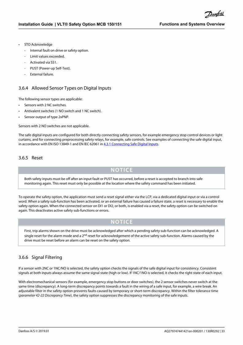
Illustration 20: Connecting the Shielded Wire
7. Remove the knock-out in the extended LCP frame so that the option fits under the frame.
8. Fit the extended LCP frame and terminal cover.
InstallationInstallation Guide | VLT® Safety Option MCB 150/151
AQ279747441421en-000201 / 130R0292 | 41Danfoss A/S © 2019.01

1
2
10 m
m
e30b
d009
.11
1 2 3 4765
108 9
11 12
Illustration 21: Connecting Control Wiring
N O T I C EThe connections are not pre-wired from the factory.
9. Fit the LCP or blind cover in the extended LCP frame.
Connect power to the drive.
Set up the input/output functions in the corresponding parameters as mentioned in the chapter Safe Plug-in in the VLT® MotionControl Tool MCT 10 Operating Guide.
The commissioning test report is automatically generated via the Safe Plug-in in MCT 10 after downloading the parameters to thesafety option.
W A R N I N GPROPER GROUNDING
Qualified personnel, in this case the operator or electrical installer, is responsible for proper grounding and compliancewith all applicable national and local safety regulations. Failure to have qualified personnel doing the wiring could result indeath or serious injury.
- Only allow qualified personnel to do the wiring of the equipment.
4.1.5 General Wiring Guidelines
Inputs
Use appropriate wiring to exclude short circuits between the inputs or to a supply line.
InstallationInstallation Guide | VLT® Safety Option MCB 150/151
AQ279747441421en-000201 / 130R029242 | Danfoss A/S © 2019.01

Output
Use separate multicore cable for supply voltages to avoid short circuits between the cable from the output (S37) to the 24 V DC supplyline.
N O T I C EAs a result of short circuits, it is no longer possible to switch off the drive terminal 37.
N O T I C EControl cables must be shielded/armored.
See the chapter Grounding of Shielded Control Cables in the VLT AutomationDrive FC 302 Design Guide for detailed specifications.
Only shielded cables are suitable for connecting encoders.
N O T I C EAll signals to the safety option must be PELV supplied and comply with EN IEC 60204.
• Route sensitive control cables - such as encoder and active safety component cables - without any interruption and with optimumshield support at both ends.
• Connect shields at both ends to the grounded enclosures through a good electrical connection and through a large surface area.
• Connect cable shields as close as possible to the cabinet cable entry.
• If possible, intermediate terminals should not interrupt cable shields.
• Retain cable shields for both power cables and for signal and data cables using the appropriate EMC clamps. The shield clampsmust connect the shield to the EMC shield bar of the shield support element for control cables through a low inductive connectionthrough a large surface area.
InstallationInstallation Guide | VLT® Safety Option MCB 150/151
AQ279747441421en-000201 / 130R0292 | 43Danfoss A/S © 2019.01

4.1.6 Connector Pin Assignment
Table 9: Connector Pin Assignment, VLT® Safety Option MCB 150
Y30 Pin Name Description
1 2 3 4 5 6 7 8 9 10 11 12
e3
0b
c31
5.1
1 1 DI1 A Digital input 1 A channel
2 GND Digital GND
3 DI1 B Digital input 1 B channel
4 ENC A Encoder channel A
5 DI2 A Digital input 2 A channel
6 ENC nA Encoder channel A inverted
7 ENC B Encoder channel B
8 DI2 B Digital input 2 B channel
9 ENC nB Encoder channel B inverted
10 24 V Power output
11 GND Supply GND
12 S37 STO enable
e3
0b
c32
5.1
2
MCB 150
Safe Option
SW. ver. xx. xx
Option B130B3280
LED:
1 2 3 4TTL Enc.interface
Y30/
DI1
A
GN
D
DI1
B
ENC
A
DI2
A
ENC
nA
ENC
B
DI2
B
ENC
nB
24V
GN
D
S37
1 2 3 4 5 6 7 8 9 10 11 12
Illustration 23: Nameplate MCB 150
InstallationInstallation Guide | VLT® Safety Option MCB 150/151
AQ279747441421en-000201 / 130R029244 | Danfoss A/S © 2019.01
Table 10: Connector Pin Assignment, VLT® Safety Option MCB 151
Y31 Pin Name Description
1 2 3 4 5 6 7 8 9 10 11 12
e3
0b
c31
5.1
1 1 DI1 A Digital input 1 A channel
2 GND Digital GND
3 DI1 B Digital input 1 B channel
4 ENC A Encoder channel A/VLT® Sensorless Safety MCB159
5 DI2 A Digital input 2 A channel
6 GND Digital GND
7 ENC B Encoder channel B
8 DI2 B Digital input 2 B channel
9 GND Digital GND
10 24 V Power output
11 GND Supply GND
12 S37 STO enable
e3
0b
c32
6.1
2
MCB 151
Safe Option
SW. ver. xx. xx
Option B130B3290
LED:
1 2 3 4HTL Enc.interface
Y31/
DI1
A
GN
D
DI1
B
ENC
A
DI2
A
ENC
B
DI2
B
24V
GN
D
S37
1 2 3 4 5 6 7 8 9 10 11 12
GN
D
GN
D
Illustration 25: Nameplate MCB 151
4.2 Encoder
4.2.1 Allowed Encoder Cable Length
The allowed cable length depends on the selected encoder. The longest cable can be achieved when using bipolar TTL encoders.Unipolar HTL encoders only allow a shorter length. In this case, the encoder power supply voltage plays a decisive role. The maximumcable length for HTL encoders used as unipolar encoder (in this case only 1 signal is evaluated) is 100 m (328 ft).
The maximum cable length for TTL encoders used as bipolar encoder (in this case both signals A/nA or B/nB) is 150 m (492 ft).
The minimum cross-section of the power supply conductor is 0.75 mm2 (18 AWG).
InstallationInstallation Guide | VLT® Safety Option MCB 150/151
AQ279747441421en-000201 / 130R0292 | 45Danfoss A/S © 2019.01

N O T I C EShield all proximity switch sensor/encoder cables. Connect the shield to the chassis at both ends. Always connect the chassison the rotary encoder to the chassis of the drive.
N O T I C EEQUIPMENT DAMAGE
Plugging in or pulling off sensor connections during operation can damage the electrical components of the encoder.
- Always de-energize connected encoders and the safety option before plugging in or pulling off encoder connections.
- For data signals or track A and track B, use lines twisted in pairs for signal transmission according to RS485.
- Select the wire cross-section in each individual case in compliance with the current consumption of the encoder and thecable length required for the installation.
Diagnostics are performed on the encoder input signals. If the encoder diagnostic tests fail, error 99 (Safe State Fault) occurs.
4.2.2 Encoder Wiring Examples
See examples of how to connect encoder power and encoder signals in illustration 26 and illustration 27.
e3
0b
c37
4.1
2
A
B
24 V
GND
4
7
10
11
FC 302
MCB 151
Illustration 26: Y31/Connecting Power and Encoder Signals to HTL Encoder (VLT® Safety Option MCB 151)
InstallationInstallation Guide | VLT® Safety Option MCB 150/151
AQ279747441421en-000201 / 130R029246 | Danfoss A/S © 2019.01

e3
0b
c37
5.1
2
A
B
24 VGND
4
7
1011
nA 6
nB 9
FC 302
MCB 150
Illustration 27: Y30/Connecting Power and Differential Encoder Signals to TTL Encoder (VLT® Safety Option MCB 150)
The TTL encoder in illustration 27 is shown with 24 V supply and TTL output. If an encoder for 5 V supply must be connected, use a 5 Vexternal supply.
4.2.3 Proximity Switch
An inductive proximity switch, detecting already present mechanical parts, for example a gear wheel, is a frequently used alternative tostandard encoders. The required minimum number of pulses per revolution (PPR) is 2 on the motor shaft while considering the gearratio.
e3
0b
c37
6.1
2
A
24 V
4
10
11GND
FC 302
MCB 151
Illustration 28: Y/31 Connecting VLT® Safety Option MCB 151 to Proximity Switch (only HTL)
N O T I C EShield and terminate the proximity switch cable to chassis at both ends (at the proximity switch side and at the option side).
InstallationInstallation Guide | VLT® Safety Option MCB 150/151
AQ279747441421en-000201 / 130R0292 | 47Danfoss A/S © 2019.01

>2x S1
2
3
n
S /2n
e3
0b
c31
4.1
1
1 Measuring plate
3 Disc (non-conducting material)
2 Proximity switch
Illustration 29: Gear Wheel for Proximity Switch
The operating distance S, set to half the nominal operating distance Sn, corresponds approximately to the optimum conditionsregarding resolution and switching frequency.
N O T I C EWhen using PNP proximity switch as encoder feedback, set parameter 42-14 Feedback Type to [1] Without direction info.
4.2.4 VLT® Sensorless Safety MCB 159
The VLT® Sensorless Safety MCB 159 option provides safe speed monitoring functions (SLS, SMS) to a VLT® Safety Option MCB 151without the need of an external speed signal. It can easily replace a speed sensor in applications where typically proximity switches areused as a speed feedback. Only 1 wire connects the MCB 159 option to the MCB 151.
InstallationInstallation Guide | VLT® Safety Option MCB 150/151
AQ279747441421en-000201 / 130R029248 | Danfoss A/S © 2019.01

e30b
g831
.10
Illustration 30: The MCB 159 Installed
4.2.4.1 Connecting a VLT® Sensorless Safety MCB 159 (MCB 151 Only)
Procedure
1. Connect the cable marked TER4:ENC A on the MCB 159 to terminal 4 on the MCB 151.
e3
0b
g8
37
.10
A
24 V
4
10
11GND
FC 302
MCB 151
MCB 159
InstallationInstallation Guide | VLT® Safety Option MCB 150/151
AQ279747441421en-000201 / 130R0292 | 49Danfoss A/S © 2019.01

4.3 Application Examples
4.3.1 Connecting Safe Digital Inputs
This section contains examples of connecting the fail-safe digital input according to EN ISO 13849-1 and EN IEC 62061. The examplesapply in cases where all components are installed in a control cabinet.
e3
0b
c30
9.1
2
A
B
1
10
312
11
12
37
20
MCB15x
A 2-channel emergency stop switch B Drive
Illustration 32: Connecting a Sensor, for Example 2-channel Emergency Stop Mushroom Push Button or Limit Switch
e3
0b
c31
0.1
2
1
24 V DC
3
12
11
12
37
20
MCB15x
0 V
OSSD 2OSSD 1Tx Rx
AB
A Drive
Illustration 33: Connecting an Electronic Sensor, for Example Safety Light Curtain
1
3
12
11
12
37
20
MCB15x
e3
0b
c31
1.1
2
10
C
BA
A Actuator
C Drive
B Switch
Illustration 34: Connecting 1 NO/1 NC Sensor, for Example Magnetic Switch
InstallationInstallation Guide | VLT® Safety Option MCB 150/151
AQ279747441421en-000201 / 130R029250 | Danfoss A/S © 2019.01

1
12
11
12
37
20
MCB15x
e3
0b
c31
2.1
2
324 V DC
A
b
c
0 V
D
A Safety PLC
C GND
B Safety output
D Drive
Illustration 35: Connecting a Digital Output Module, for Example Safety PLC
A
10
1
312
11
12
37
20
MCB15xe
30
bc3
13
.12
B
Illustration 36: Connecting a Sensor, for Example 1-channel Emergency Stop Mushroom Push Button or Limit Switch
N O T I C EAll equipment used must be suitable for the selected category/PL or SIL.
N O T I C EUse of a 1-channel E-stop switch provides no input redundancy and no ability for the safety option to monitor for input shortcircuits. One-channel E-stop switches used with a safety option are suitable only for category 2 applications, per EN ISO 13849-1PL c or SIL1.
When a 1-channel E-stop is used, guard against failure modes that can result in an unsafe condition. An example of an unsafe conditioncould be the failure of the contact to a short circuit condition. A switch with positive opening operation should be used to reduce thepossibility of a failure of the switch to open. A short-circuit failure results in loss of switching function. This failure can occur from ashort across the switch contacts, a short across the wires connected to the switch between the switch and the safety option, or a shortto a secondary source of power. To reduce these risks, physically separate the wires from each other and from other sources of power(for example, in separate wire ways or conduit). According to the definition of European standard EN ISO 13849-1, a 1-channel E-stopcould be used in applications where PL c or less (b or a) has been determined via a risk-assessment procedure.
InstallationInstallation Guide | VLT® Safety Option MCB 150/151
AQ279747441421en-000201 / 130R0292 | 51Danfoss A/S © 2019.01

e3
0b
c96
0.1
1
E-Stop
MCB15x
1
10
312
11
12
37
20
FC
12
37
20
FC
12
37
20
FC
Illustration 37: Example of Multiple Drives in Daisy Chain
Up to 3 drives may be connected in a daisy chain. Total cable length must not exceed 30 m (98.4 ft).
InstallationInstallation Guide | VLT® Safety Option MCB 150/151
AQ279747441421en-000201 / 130R029252 | Danfoss A/S © 2019.01

5 Commissioning
5.1 Before Commissioning
5.1.1 Safety Guidelines
When commissioing/decommissioning:
• Secure the site in accordance with regulations (barrier, warnings, signs, and more). Only qualified personnel is allowed tocommission/recommission the system.
• Refer to the guidelines, information, and specifications stated in the operating guide of the relevant programmable control system.
• Make sure that no personal injury and/or material damage can occur, even if the plant/machine moves unintentionally.
C A U T I O NELECTROSTATIC DISCHARGE
Electrostatic discharge can damage components.
- Ensure discharge before touching the safety option, for example by touching a grounded, conductive surface or by wearinga grounded armband.
W A R N I N GRISK OF ELECTROCUTION
Wiring the electrical connections on the drive while voltage is applied can lead to death or serious injury.
- Switch off power.
- Make sure that the control cabinet is provided with an access lock or warning signs.
- DO NOT switch on voltage until the system is commissioned.
Refer to the VLT® AutomationDrive FC 301/FC 302 Operating Guide for further information on the drive. Refer to the VLT® MotionControl Tool MCT 10 Operating Guide for further information on the Safe Plug-in.
5.1.2 Commissioning Requirements
Context:
Observe the following:
• When setting up the option for the 1st time, ensure to have a commissioning report at hand, see further information in the VLT®Motion Control Tool MCT 10 Operating Guide.
N O T I C EOnly LCP SW version 7.0 or newer is supported.
Prerequisites:
The following components are required to perform the necessary steps for commissioning the safety option:
CommissioningInstallation Guide | VLT® Safety Option MCB 150/151
AQ279747441421en-000201 / 130R0292 | 53Danfoss A/S © 2019.01

• Installation of MCT 10 Set-up Software version 4.40 or later.
• Successful connection to VLT AutomationDrive FC 302 with integrated safety option.
• USB or fieldbus connection or RS485 Interface adapter for connecting the control card of the drive with the PC.
N O T I C EIf RS485 is used, set the protocol for serial communication to [0] FC-MC in parameter 8-30 Protocol (only accessible through theLCP).
Procedure
1. Configure the safety option in the MCT 10 with Safe Plug-in. Ensure only to configure safety sub-functions that are wired up to thesafety option inputs.
2. Ensure that the device number (serial number and ordering number) of the safety option on the drive matches the device numberof the safety option in the MCT 10 Safe Plug-in.
Ensure that the drive is ready for commissioning (see VLT AutomationDrive FC 302 Operating Guide).
5.2 Initial Commissioning
5.2.1 Power-up/Self-test
Once the power supply has been applied to the drive, the safety option performs a self-test. During the self-test phase, all LEDs light up(lamp test) and the message Safe Opt. initialized - SO RESET requested or SO in Self-test appears. After power-up, the LEDs light upaccording to the device status.
N O T I C EIf the supply voltage of the safety option exceeds the allowed range, the safety sub-function STO is triggered. The safety-related output S37 on the option is switched off.
5.2.2 Start Commissioning
1. Connect the configuration PC to the drive or motion control system.
A Make the interface in the MCT 10 Safe Plug-in (refer to the chapter Functional Safety Configuration Plug-in in the VLT® MotionControl Tool MCT 10 Operating Guide and the Tool-Tip for help.
2. Switch on the supply voltages.
A Switch on all the supply voltages for the drive and the safety option.
The display elements on the drive and on the safety option show when they are ready for operation. Thedisplay elements on the safety option are described in 5.3 Operation.
3. Download the configuration file.
A Select Write to drive in the MCT 10 Safe Plug-in to establish communication between the PC and the drive.
B Make sure that no other system is accessing the interface.
C Apply password, unequal to default password.
D On multi-axis systems, the safety option can be selected individually for the download. The configuration is distributed to thesafety options via the MCT 10 Set-up Software.
When the configuration file is downloaded, the LCP reads SO Custom. completed. During download, the following is checked in theconfiguration:
CommissioningInstallation Guide | VLT® Safety Option MCB 150/151
AQ279747441421en-000201 / 130R029254 | Danfoss A/S © 2019.01

• Feasibility of the configuration data.
• Proper wiring.
• Correct device number (ordering number). If the self-test is successful, the power element of the drive is enabled.
N O T I C EUp to 10 s may elapse before the safety option is ready for operation.
5.2.3 Safety Option Customization
The following LCP messages indicate the different states of the customization process.
LCP message Description
e30b
d125
.11
Status
SO C us tom. requested
!1(1)0 R PM None 0.00 KW
!Safe Stop [W68]
MCT 10 customization of the safety option is requested.
e30b
d124
.11
Status
SO Custom. abortedSO RESET required!
!1(1)0 RPM None 0.00KW
!Safe Stop [W68]Off Remote SO Req.RESET
MCT 10 customization of the safety option is aborted.
e30b
d122
.11
Status
SO Custom. completedSO RESET required!
!1(1)0 RPM None 0.00KW
!Safe Stop [W68]Off Remote SO Req.RESET
MCT 10 customization of the safety option is complete.
CommissioningInstallation Guide | VLT® Safety Option MCB 150/151
AQ279747441421en-000201 / 130R0292 | 55Danfoss A/S © 2019.01

5.2.4 Setting Up the Encoder
Context:
N O T I C EIf the selected encoder resolution is below 150 PPR for HTL/TTL encoder, set a feedback filter value in parameter 42-15 FeedbackFilter. The system then calculates an allowed value. This is also the case when using a proximity switch feedback where theencoder resolution is below 600 PPR.
N O T I C EDepending on the system, a movement can imply different directions for the motor encoder.
N O T I C EDepending on the application, the motor encoder may be connected via a gearbox.
Procedure
1. Select the type of feedback device, either [1] Safe Option or [0] None in parameter 42-10 Measured Speed Source. For SS1 time delayfunctionality, no feedback source is necessary.
2. Set the feedback parameters for the safety option.
In closed-loop applications, or if VLT® Sensorless Safety MCB 159 option is used, set parameter 7-00 Speed PID Feedback Source to[11] MCB 150/151.
3. Set mounting type to Motor shaft mounted or Application mounted.
Select a gear ratio within 0.0001–32.0000 (default 1) in parameter 42-13 Gear Ratio. If the MCB 159 option is used, set the gear ratioto 1.
For MCT 10 Set-up Software version 4.40 or higher: If MCB 159 is available and is to be used, set the mounting type to Sensorless.Skip steps 5 and 6 as correct values are set automatically.
4. Set the correct encoder value (1–4096 PPR) in parameter 42-11 Encoder Resolution.
If the MCB 159 option is used, set the correct encoder value to half of the number of motor pole pairs.
5. Set parameter 42-12 Encoder Direction to [0] Clockwise (default) or [1] Counter clockwise.
If the MCB 159 option is used, select Clockwise.
6. Set parameter 42-14 Feedback Type to [0] With direction info or [1] Without direction info.
Select [1] Without direction info if a VLT® Sensorless Safety MCB 159 option or a proximity switch sensor is used for speeddetection.
5.2.5 Commissioning Test
The MCT 10 Safe Plug-in creates a commissioning report based on the commissioning test result. It generates the drive safetysignature. This function provides a final report when the safety option has been configured. This report is considered as a help tool forsafety commissioning and validates that all the safety sub-functions are operational. The commissioning report can either be printed orconverted into a PDF file.
CommissioningInstallation Guide | VLT® Safety Option MCB 150/151
AQ279747441421en-000201 / 130R029256 | Danfoss A/S © 2019.01

The test objective is to verify proper implementation (forced dormant error detection measures) and to examine the response ofspecific monitoring functions to the explicit input of values outside tolerance limits.
W A R N I N GUNEXPECTED BEHAVIOR
Modifying or changing hardware and/or software components can lead to unexpected behavior of the drive. This behaviorcould result in death or serious injury.
- Ensure that all protective equipment is closed before system start-up and activation of the drive.
- Keep personnel out of the danger zone.
- Carry out a partial or complete commissioning test (mandatory).
- Test the steady control response by briefly moving the drive in forward and reverse direction before allowing anybody toreenter the danger zone.
EN IEC 61508, EN IEC 62061 and EN ISO 13849 require that the final assembler of the machine validates the operation of the safety sub-function with a commissioning test. The commissioning tests for the standard safety sub-functions Safe Stop of the drive are describedin the drive manuals. The tests for the optional safety sub-functions are described in the commissioning report generated by the MCT10 Safe Plug-in. The commissioning test must be performed:
• At initial start-up of the safety sub-function.
• After any changes related to the safety sub-function (wiring, components, settings, and more).
• After any maintenance work related to the safety sub-function.
5.3 Operation
W A R N I N GUNINTENDED BEHAVIOR
Numerous stored data or settings control the behavior of the drive system. Unsuitable settings or data may trigger unexpectedmovements or responses to signals and disable monitoring functions. Follow the instructions below to avoid risk of death,serious injury, or equipment damage.
- Do NOT operate the drive system with unknown settings or data.
- Verify that the stored data and settings are correct.
- When commissioning, carefully run tests for all operating states and potential error situations.
- Verify the functions after replacing the product and also after changing the settings or data.
- Only start the system if there are no persons or obstructions in the hazardous area.
Prerequisites for normal operation are:
• Commissioning is complete.
• The safety option contains the configuration data.
• The safety sub-functions have been tested.
• LED1, LED2, and LED4 are lit.
During operation:
• Any pulse edge change at the safety option safe input is monitored.
• The safety sub-functions are performed in accordance with the configuration.
CommissioningInstallation Guide | VLT® Safety Option MCB 150/151
AQ279747441421en-000201 / 130R0292 | 57Danfoss A/S © 2019.01

6 General Parameter Set-up
6.1 Configuration
6.1.1 General Parameter Set-up
See 6.3 Parameter List to configure an operation of the safety option. The set-up is done via the MCT 10 Safe Plug-in.
Speed monitoring by the safety option
If an external encoder is connected to the safety option and selected in parameter 42-10 Measured Speed Source, speed monitoring isactive all the time whether a safety sub-function is requested or not. However, if an STO is triggered (either directly, or as aconsequence of a Safe Stop 1) it interrupts the speed monitoring.
Encoder configuration
To define the type of feedback used by the safety option, select [1] Safe option in parameter 42-10 Measured Speed Source.
6.1.2 Configuration of Safety Sub-functions
The safety sub-functions to be carried out by the safety option are defined in the MCT 10 Safe Plug-in:
• Configurations of the safety sub-functions.
• Setting of limit values, braking ramps for the safety sub-functions, monitoring of motion sequences.
N O T I C EAlways perform the required commissioning test. The commissioning test report is automatically generated via the Safe Plug-inin MCT 10 after downloading the parameters to the safety option.
Downloading the configuration to the safety option:
• On single-drive systems, via the RS486/USB interface on the drive.
• On networked systems, via RS485 or fieldbus interface on the MCT 10 Safe Plug-in. The control system passes the configuration tothe respective safety option.
• The feasibility of the configuration is checked when it is downloaded.
Further information on configuration and setting parameters for the safety sub-functions is available in the online help for the MCT 10Safe Plug-in and in the VLT® Motion Control Tool MCT 10 Operating Guide.
The safety option is configured with the commissioning software MCT 10 Set-up Software via a Safe Plug-in. The Safe Plug-in in thecommissioning software is available as default from version 3.18, all functions are available from MCT 10 Set-up Software version 4.40.
The commissioning software provides the following menu items for the safety option:
General Parameter Set-upInstallation Guide | VLT® Safety Option MCB 150/151
AQ279747441421en-000201 / 130R029258 | Danfoss A/S © 2019.01

• General speed monitoring.
• Safe input.
• Safe Stop 1.
• Safely Limited Speed.
• Safe Maximum Speed.
• Parameters.
• Status.
The menu items are described in detail in the VLT® Motion Control Tool MCT 10 Operating Guide.
The menu item Status shows the following:
• Current signal states of inputs and outputs.
• Option operating mode
• Active safety sub-function.
The states of the inputs and output cannot be changed via the commissioning software.
6.1.3 Password Protection
Use a password to protect the system configuration. A password must be entered only when changing safety option parameters(writing to option).
Default password is 12345678.
It is advised to change the safety option default password before downloading the parameter values of a safety option with factorysettings. Only persons knowing the password can change the safety option parameter values.
N O T I C EAny misuse of password may lead to severe safety problems.
N O T I C ENo password is required to access the commissioning parameters of the safety option. The password is required when theparameters must be downloaded to the option via Write to Drive.
The password must be of 8 characters and is case-sensitive. Alphanumeric characters and symbols are valid for password.
The safety option checks the parameter password entered. Use the menu item Change Password to change the safety optionparameter password. Change the safety option password if there is any indication of manipulation.
6.1.3.1 Resetting the Password
Context:
N O T I C EResetting the password resets all option parameters to factory default.
General Parameter Set-upInstallation Guide | VLT® Safety Option MCB 150/151
AQ279747441421en-000201 / 130R0292 | 59Danfoss A/S © 2019.01

Procedure
1. In the Administration menu, select Reset.
2. Checkmark Yes, I want to reset Safe Option configuration in the drive.
3. Enter the default password (12345678).
4. Click Reset.
5. On the prompt that appears, click Yes.
6. Change the safety option password.
6.2 Reset and Status over Fieldbus
6.2.1 Reset of Safety Option and Pending Safe Function
There are 2 different methods of resetting the safety option and pending safe function. The configuration of parameter 42-31 ResetSource is decisive for which method to use.
If parameter 42-31 Reset Source is set to [0] Drive Reset, a reset according to the selected control word profile is required.
N O T I C EThe drive-specific alarms are also reset.
If parameter 42-31 Reset Source is set to [1] Drive Safe Reset, configure [3] Safe Option Reset in parameter 8-14 Configurable Control WordCTW.
N O T I C EThe drive-specific alarms are not reset and the control word profile is overwritten.
6.2.2 Retrieving Safety Option Status
A subset of the safety option status can be retrieved as part of the status word. Its behavior changes based on the selected controlword profile.
Configure [91] Safe Opt. Reset. req and [90] Safe Function active in parameter 8-13 Configurable Status Word STW to:
• Indicate that a reset of the safety option is required.
• Indicate that a safe function is active.
Parameter 42-80 Safe Option Status indicates the actual status (active safe function, any requests, and error number) of the safety optionand is accessible as read-only parameter from any interface or configurable as read process data for a specific fieldbus.
N O T I C EOnly active safe function is set in Safety Option Status.
General Parameter Set-upInstallation Guide | VLT® Safety Option MCB 150/151
AQ279747441421en-000201 / 130R029260 | Danfoss A/S © 2019.01

Table 11: Explanation of the Status Bits for Safety Option Status
Bit Description
0 Normal_up
1 PUST
2 STO active
3 SS1-a active
4 SS1-b active
5 SLS-a active
6 SLS-b active
7 Safe Maximum Speed active
8 Reserved for further SP
9 Reserved for further SP
10 Reserved for further SP
11 Int_fail
12 Reset required
13 Pending fail-safe state
14 Ext_fail
15 Safe function pending
16 General reset
17 Customization_confirmed
18 Customization_aborted
19 Customization_requested
20 Suspension of speed monitoring
21 PUST warning
22 DI_1_offline_warning
23 DI_2_offline_warning
24 Error code
25 Error code
26 Error code
27 Error code
28 Error code
29 Error code
30 Error code
31 Error code
General Parameter Set-upInstallation Guide | VLT® Safety Option MCB 150/151
AQ279747441421en-000201 / 130R0292 | 61Danfoss A/S © 2019.01

Table 12: Bit Functions
Bit number Bit name Value Function
00 Safety sub-function deactive/active 0 Safety sub-function, fail-safe reaction is active or pending, orwarning is active.
1 Normal operation.
01 Power up self-test 1 Safety option is in PUST state.
02 Safe Torque Off 0 Safe Torque Off is not active.
1 Safe Torque Off is active.
03 Safe Stop 1 a 0 Safe Stop 1 a is not active.
1 Safe Stop 1 a is active.
04 Safe Stop 1 b 0 Safe Stop 1 b is not active.
1 Safe Stop 1 b is active.
05 Safely Limited Speed a 0 Safely Limited Speed-a is not active.
1 Safely Limited Speed-a is active.
06 Safely Limited Speed b 0 Safely Limited Speed-b is not active.
1 Safely Limited Speed-b is active.
07 Safe Maximum Speed 0 Safe Maximum Speed is inactive.
1 Safe Maximum Speed is active
08–10 Reserved for future safety sub-functions. – –
11 Internal failure 0 No internal failure is active.
1 Internal failure is active.
12 Reset 0 No safety option reset required.
1 Safety option reset required.
13 Pending fail-safe state 0 No pending fail-safe state.
1 Safety option is in this state at each power-up.
14 External failure 0 No external failure is active.
1 External failure is active.
15 Safe function pending 0 No safe function pending.
1 Safe function pending.
16 General reset 0 No change in state.
1 General reset is done.
17 Customization confirmed 0 No change in state.
1 Customization confirmed.
18 Customization aborted 0 No change in state.
1 Customization aborted.
General Parameter Set-upInstallation Guide | VLT® Safety Option MCB 150/151
AQ279747441421en-000201 / 130R029262 | Danfoss A/S © 2019.01

Bit number Bit name Value Function
19 Customization requested 0 No change in state.
1 Customization is requested.
20 Suspension of speed monitoring 0 No change in state.
1 Suspension of speed monitoring - see error code.
21 Power Up Self-Test warning 0 No change in state.
1 Power Up Self-Test warning is issued.
22 Digital input 1 offline test warning 0 No change in state.
1 Digital input 1 offline test warning.
23 Digital input 2 offline test warning 0 No change in state.
1 Digital input 2 offline test warning.
24–31 Causes for possible internal or external errors. See error code.
N O T I C EParameter 42-81 Safe Option Status 2 indicates which digital input of the safety option is either activated, in pending state, or inblank initial state.
Table 13: Explanation of the Status Bits for Safety Option Status 2
Bit Description State
0 DI1 safety status 00 - Inactive
01 - Active
10 - Pending
1
2 DI 2 safety status 00 - Inactive
01 - Active
10 - Pending
3
4 Blank initial state 0 (inactive/1 (active)
5 Unused
31
Table 14: Bit Functions, Status 2
But number Bit name Value Function
00-01 DI1 safety status 00 Inactive.
01 Active.
10 Pending.
General Parameter Set-upInstallation Guide | VLT® Safety Option MCB 150/151
AQ279747441421en-000201 / 130R0292 | 63Danfoss A/S © 2019.01

But number Bit name Value Function
02-03 DI2 safety status 00 Inactive.
01 Active.
10 Pending.
04 Blank initial state 0 Safety option is configured.
1 Safety option is in blank initial state.
05–31 Reserved for future use
6.3 Parameter List
Table 15: Safety Option Parameters
Group Groupname
Parameter Value range/available op-tions
Default Description Con-ver-sionindex
Datatype
42-0* SpeedPerform-ance
42-00Speed Devi-ation Timer
10–5000 ms 10 ms Enter the time for which a speed devi-ation above 120 RPM between esti-mated and measured speed is al-lowed.
1 u_int16
42-01 FastRamp
[0] No [0] No Select [1] Yes if fast ramping is neededwith poor resolution of measuredspeed.
– u_int8
[1] Yes
General Parameter Set-upInstallation Guide | VLT® Safety Option MCB 150/151
AQ279747441421en-000201 / 130R029264 | Danfoss A/S © 2019.01

Group Groupname
Parameter Value range/available op-tions
Default Description Con-ver-sionindex
Datatype
42-1* SpeedMonitor-ing
42-10MeasureSpeedSource
[0] None [1] Safe Op-tion
The source of the speed feedback. 0 u_int8
[1] Safe Option
42-11 En-coder Reso-lution
1–4096 PPR (foroption withHTL encoder)
1024 PPR Encoder or proximity switch resolu-tion of the encoder connected to theMCB 150 TTL and MCB 151 HTL.
0 u_int16
1–10000 PPR(for option withTTL encoder)
42-12 En-coder Di-rection
[0] Clockwise [0] Clock-wise
Allows for changing the detected en-coder rotation direction withoutchanging the wiring to the encoder.
– u_int8
[1] Counterclockwise
42-13 GearRatio
0.0001–32.0000 1 Ratio between motor speed and en-coder speed. Remark: Only used whengear mounted.
-4 u_int32
42-14 Feed-back Type
[0] With direc-tion info
[0] With di-rection info
The feedback can be with or withoutdirection information. For TTL/HTL en-coder, direction info is available. Forproximity switch, select [1] Without Di-rection Info.
– u_int8
[1] Without di-rection info
42-15 Feed-back Filter
0.01–200.00 Hz 200 Hz Frequency of the feedback filter. De-fault value is 200 Hz (off) if the encod-er resolution is higher than 150 PPR. Afilter value of 200 Hz is selected,meaning that the filter is off. The useof filters depends on the given encod-er resolution, gear ratio, and feedbacktype.
-2 u_int16
42-17MountingType
[0] Motor ShaftMounted
[0] MotorShaft Moun-ted
Location where the measured speedsource is mounted.
– u_int8
[1] ApplicationMounted
[2] Sensorless
42-18 ZeroSpeed Tim-er
0–10000 h 8760 h Time period where the option is al-lowed to be below 120 RPM when SLSis active before STO is activated.
74 u_int16
42-19 ZeroSpeed Limit
Fixed 120 RPM 67 u_int16
General Parameter Set-upInstallation Guide | VLT® Safety Option MCB 150/151
AQ279747441421en-000201 / 130R0292 | 65Danfoss A/S © 2019.01

Group Groupname
Parameter Value range/available op-tions
Default Description Con-ver-sionindex
Datatype
42-2* Safe In-put
42-20 SafeFunction
[0] STO [0] STO This can be 1 of the safety sub-func-tions or disabled. Remark: Both SafeInputs can NOT be disabled at thesame time.
– u_int8
[1] SS1-a
[2] SS1-b
[3] SLS-a
[4] SLS-b
[5] disable
42-21 Type [0] NCNC [0] NCNC NCNC, antivalent (NC/NO) or 1NC. – u_int8
[1] Antivalent
[2] NC
42-22 Dis-crepancyTime
0–5000 ms 10 ms An adjustable filter time preventsfaults caused by temporary discrepan-cy.
-3 u_int16
42-23 Sta-ble SignalTime
0–5000 ms 10 ms An adjustable signal filter in the safetyoption suppresses temporary signalchanges using test pulse pattern.
-3 u_int16
42-24 Re-start Behav-ior
[0] Manual [0] Manual In case of an activated safety sub-function, the safety option can eitherrestart automatically or wait for a RE-SET signal from the user.
– u_int8
[1] Automatic
42-3* General 42-30 Exter-nal FailureReaction
[0] STO [0] STO Safety sub-function that is executed ifthere is an external failure.
– u_int8
[1] SS1-a
[2] SS1-b
42-31 ResetSource
[0] Drive Reset [0] Drive Re-set
Source for the RESET of the safety op-tion. Can either be executed on theoption input DI2, via fieldbus or digi-tal input on the drive or via the LCP.By selecting Drive Safe Reset, only thesafety option is reset.
– u_int8
[1] Drive SafeReset
[2] Safe OptionDI1_A
42-33 Pa-rameter SetName
Visible String,length: 8
SafeSet1 Name of the safe parameter Set (mustbe 8 characters to avoid a bad cus-tomization data error).
General Parameter Set-upInstallation Guide | VLT® Safety Option MCB 150/151
AQ279747441421en-000201 / 130R029266 | Danfoss A/S © 2019.01

Group Groupname
Parameter Value range/available op-tions
Default Description Con-ver-sionindex
Datatype
42-4* SS1 42-40 Type [0] Delay [0] Delay The type of the SS1 safety sub-func-tion.
– u_int8
[1] Ramp(slope)
[2] Ramp (time)
42-41 RampProfile
[0] Linear [0] Safe Op-tion Linear
The ramp profile for an SS1 Delay canbe either specified as linear or S-ramp.
– u_int8
[2] S-rampConst Time
42-42 DelayTime
0.1–3600.0 s 1.0 s Time until STO is activated. -1 u_int16
42-43 DeltaT
0–99% 2% Δ T subtracts from the time in param-eter 42-42 Delay Time to get motor tostop before the timer expires.
0 u_int8
42-44 De-celerationRate
1–30000 RPM/s 1500 RPM/s Deceleration rate for the SS1 slope-based ramp type.
0 u_int16
42-45 DeltaV
1–10000 RPM 120 RPM Tolerance between calculated and ac-tual speed that the safety option al-lows.
67 u_int16
42-46 ZeroSpeed
1–600 RPM 10 RPM When this speed is reached, the safetyoption activates the STO.
67 u_int16
42-47 RampTime
0.1–3600.0 s 1.0 s Time to ramp down to 0 RPM. -1 u_int16
42-48 S-ramp Ratioat Decel.Start
1 to (100 -42-49 S-rampRatio at Decel.End)%
50% The proportion of the total ramp-down time (parameter 42-42 DelayTime) where the deceleration torqueincreases. The larger the percentagevalue, the greater the jerk compensa-tion achieved, and thus the lower thetorque jerks in the application.
0 u_int8
42-49 S-ramp Ratioat Decel.End
1 to (100 -42-48)%
50% The proportion of the total ramp-down time (parameter 42-42 DelayTime) where the deceleration torquedecreases. The larger the percentagevalue, the greater the jerk compensa-tion achieved, and thus the lower thetorque jerks in the application.
0 u_int8
General Parameter Set-upInstallation Guide | VLT® Safety Option MCB 150/151
AQ279747441421en-000201 / 130R0292 | 67Danfoss A/S © 2019.01

Group Groupname
Parameter Value range/available op-tions
Default Description Con-ver-sionindex
Datatype
42-5* SLS 42-50 CutOff Speed
(42-51 + 1) to10000 RPM
270 RPM Speed at which the fail-safe reactiongets activated. This should be the val-ue of parameter 42-51 Speed Limit plusa tolerance.
67 u_int16
42-51Speed Limit
0 to (42-50 - 1)RPM
150 RPM Maximum speed allowed when theSLS function is active.
67 u_int16
42-52 FailSafe Reac-tion
[0] STO [0] STO Safety sub-function that is activated, ifthe speed exceeds the limit. Only forSLS.
– u_int8
[1] SS1-a
[2] SS1-b
42-53 StartRamp
[0] No [0] No If the speed at activation of SLS ishigher than the speed limit, it rampsdown to the speed limit (yes) or acti-vate an STO (no).
– u_int8
[1] Yes
42-54 RampDown Time
0.1–3600.0 s 1.0 s Ramp-down time for start ramp. -1 u_int16
42-7* SMS 42-70 Acti-vation
[0] Inactive [0] Inactive Activate or deactivate SMS (Safe Maxi-mum Speed).
67 u_int8
[1] Active
42-71 CutOff Speed
120–20000 RPM
1500 RPM Maximum allowed speed – u_int16
General Parameter Set-upInstallation Guide | VLT® Safety Option MCB 150/151
AQ279747441421en-000201 / 130R029268 | Danfoss A/S © 2019.01
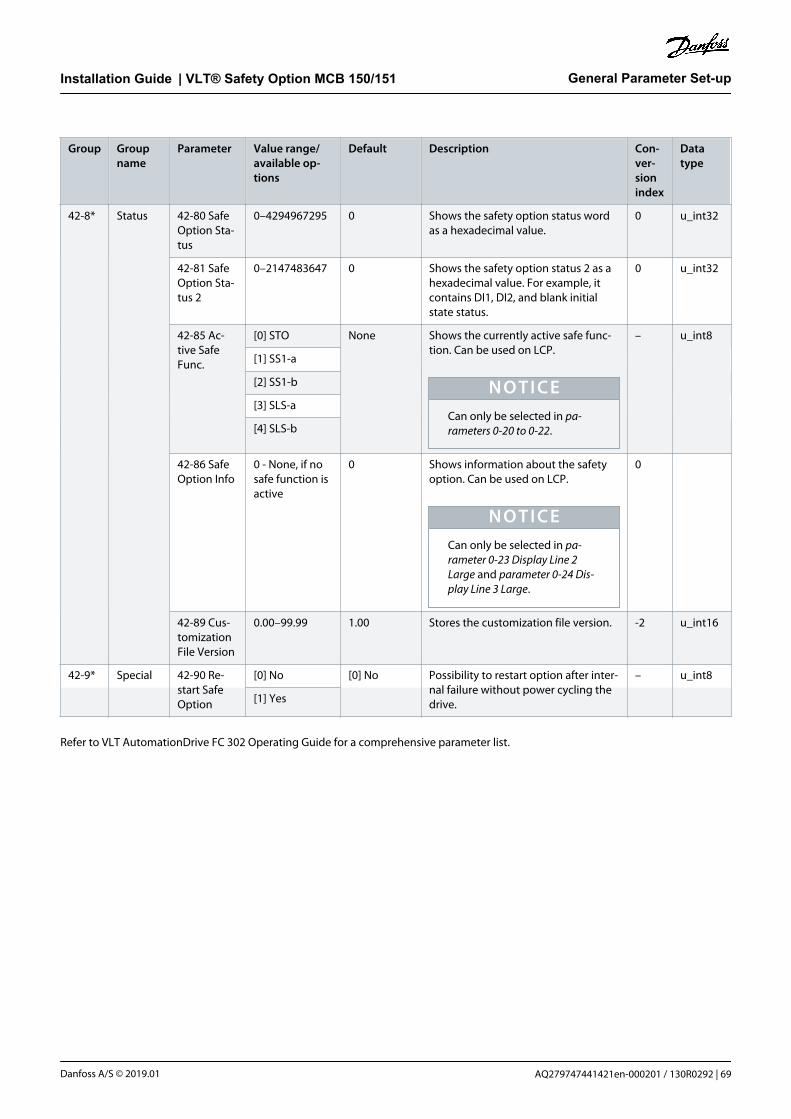
Group Groupname
Parameter Value range/available op-tions
Default Description Con-ver-sionindex
Datatype
42-8* Status 42-80 SafeOption Sta-tus
0–4294967295 0 Shows the safety option status wordas a hexadecimal value.
0 u_int32
42-81 SafeOption Sta-tus 2
0–2147483647 0 Shows the safety option status 2 as ahexadecimal value. For example, itcontains DI1, DI2, and blank initialstate status.
0 u_int32
42-85 Ac-tive SafeFunc.
[0] STO None Shows the currently active safe func-tion. Can be used on LCP.
N O T I C ECan only be selected in pa-rameters 0-20 to 0-22.
– u_int8
[1] SS1-a
[2] SS1-b
[3] SLS-a
[4] SLS-b
42-86 SafeOption Info
0 - None, if nosafe function isactive
0 Shows information about the safetyoption. Can be used on LCP.
N O T I C ECan only be selected in pa-rameter 0-23 Display Line 2Large and parameter 0-24 Dis-play Line 3 Large.
0
42-89 Cus-tomizationFile Version
0.00–99.99 1.00 Stores the customization file version. -2 u_int16
42-9* Special 42-90 Re-start SafeOption
[0] No [0] No Possibility to restart option after inter-nal failure without power cycling thedrive.
– u_int8
[1] Yes
Refer to VLT AutomationDrive FC 302 Operating Guide for a comprehensive parameter list.
General Parameter Set-upInstallation Guide | VLT® Safety Option MCB 150/151
AQ279747441421en-000201 / 130R0292 | 69Danfoss A/S © 2019.01

7 Service and Repair
7.1 Updates, Servicing, and Modifications
N O T I C EUPDATES TO FIRMWARE
Contact Danfoss to get an update of the firmware.
C A U T I O NFIRMWARE MODIFICATIONS
Unauthorized modifications made to the firmware can lead to injury and equipment damage and voids the warranty.Furthermore, Danfoss cannot be held liable for any consequences third-party changes may have on the functional safety.
- Only have Danfoss change the firmware.
C A U T I O NMODIFICATIONS TO THE UNIT
Unauthorized modifications made to the unit can lead to injury and equipment damage and voids the warranty. Furthermore,Danfoss cannot be held liable for any consequences third-party changes may have on the functional safety.
- Only have Danfoss make hardware modifications of the safety option.
W A R N I N GYEARLY TEST
The safety option functions must be tested on a yearly basis to avoid the risk of death or injury.
- Test the safety sub-function.
- Switch off the options used in the safety chain.
7.2 Repair
W A R N I N GSHOCK HAZARD
Attaching or removing the safety option while the soft starter is connected to mains voltage may cause personal injury.
- Before attaching or removing the safety option, isolate the drive from mains voltage.
N O T I C EOnly Danfoss is authorized to repair the safety option. A defect option must be returned to Danfoss.
Service and RepairInstallation Guide | VLT® Safety Option MCB 150/151
AQ279747441421en-000201 / 130R029270 | Danfoss A/S © 2019.01

7.3 Replacement of Safety Option
7.3.1 Before Removing the Safety Option
Procedure
1. Save all parameters of the safety option, see VLT® Motion Control Tool MCT 10 Operating Guide.
2. Duplicate the existing device setting.
7.3.2 Removing the Safety Option
Context:
N O T I C EThe drive generates an error message after removing the safety option.
N O T I C EIf the removed safety option is installed in another drive, the drive issues a warning for safety option parameter selection. Selectthe safety configuration from either the drive or from the safety option.
Procedure
1. Disconnect all power (power stage supply voltage and controller supply) before plugging in or removing the option.
2. Verify that no voltage is present.
3. Remove the safety option according to the instructions in the chapter Installation in the VLT AutomationDrive FC 302 OperatingGuide.
7.3.3 Replacing the Safety Option
Context:
W A R N I N GSHOCK HAZARD
Attaching or removing the safety option while the soft starter is connected to mains voltage may cause personal injury.
- Before attaching or removing the safety option, isolate the drive from mains voltage.
N O T I C EAlarm 67, Option Change informs that a change of the drive hardware configuration has occurred after a power-up. Thissituation can occur after installing/removing an option, or if an option is defect. If the configuration changes, the drive freezesthe hardware configuration, trips, and refuses to start up.
- Thus avoiding any unintended parameter changes.
When replacing the safety option, note the following:
Service and RepairInstallation Guide | VLT® Safety Option MCB 150/151
AQ279747441421en-000201 / 130R0292 | 71Danfoss A/S © 2019.01

• If the firmware version has changed, configured functions and stated parameters may no longer be supported or may have beenmodified. Adapt the configuration in the MCT 10 Set-up Software.
• Download the configuration to the safety option again.
Alternatively, copy the safe parameters using a graphical LCP, see 7.3.4 Copying Safe Parameter Set-up.
Prerequisites:
Reset all option parameters to factory setting to avoid trips caused by replacement of the safety option.
Order a new safety option at Danfoss.
Procedure
1. Replace the defective option, see 4.1 Installing the Option.
At the 1st power-up, the drive recognizes different configurations between the safety option and the drive if the safetyparameters are not set default values.
2. Select Frequency converter.
3. If configured, enter the password for the copied safety option configuration from the LCP.
4. Accept to download the safe parameters to the drive/safety option.
5. Select OK.
6. Restart the drive.
7. Download the configuration data again from either:
MCT 10 Safe Plug-in to the safety option via RS485 or USB, or
An LCP in the drive to the safety option.
A checksum is saved along with the file to allow for identification for the duplicated safety option parameters. Follow the guidedsequence on the LCP display to transfer the safety option parameters to a safety option.
Verify that the correct safety parameter file is transferred to the safety option. Perform a commissioning test, see 5.2.5Commissioning Test.
7.3.4 Copying Safe Parameter Set-up
Procedure
1. Prepare a commissioning report.
2. Select [0] All to LCP in parameter 0-50 LCP Copy. Monitor the upload on the progress bar.
3. Install the LCP with all the copied parameters on the drive that has to be updated.
4. Select [2] All from LCP in parameter 0-50 LCP Copy. The normal password protection can be applied in parameter 0-60 Main MenuPassword.
5. Enter the password for copied SO configuration (=safe parameters) from LCP.
6. Accept the download of the safe parameters to the drive, which has now a new configuration assigned to it.
7. Reset the drive to activate the new configuration.
7.3.4.1 Password Protection LCP Copy and Safe Parameter Mismatch
Optionally, a password protection can be used for the function LCP copy (see table 16) and if there is a parameter mismatch (see table17). Password protection can be enabled/disabled in parameter 0-69 Password Protection of Safety Parameters. The password is set inparameter 0-68 Safety Parameters Password. Default password is 300.
Service and RepairInstallation Guide | VLT® Safety Option MCB 150/151
AQ279747441421en-000201 / 130R029272 | Danfoss A/S © 2019.01

Table 16: LCP Copy Messages
Message Description
e30b
d114
.11
Password0-69 Password Protection of safety Parameter
1(1)0 RPM None
[1] Enabled
([0] Disabled)
The password protection of the safety parameters is enabled.e3
0bd1
16.1
1
Copy/Save0-50 LCP Copy
1(1)0 RPM None
Safety Par. from LCP
0-5*
9[ ]
Copying the safety parameters from the LCP into the drive is selected.
e30b
d117
.11
Safety Par. from LCP 1(1)0 RPM None
Copying...
00%
The safety parameters get copied from the LCP into the drive.
e30b
d118
.11
Safety PasswordPlease enter the safetyPassword
1(1)0 RPM None
00000000
If password protection is enabled in parameter 0-69 Password Protection of Safety Parameters, en-ter the correct LCP-copy/parameter mismatch password (parameter 0-68 Safety Parameters Pass-word).
e30b
d119
.11
1(1)0 RPM None
Password accepted
Pa0-
[0
([1] Enabled)
If the entered password is correct, this overlay message is shown for some seconds.
e30b
d123
.11
1(1)0 RPM None
Password rejected
Pa0-
[0
([1] Enabled)
If the entered password is wrong, this overlay message is shown for some seconds. Then the pass-word can be entered again.
Service and RepairInstallation Guide | VLT® Safety Option MCB 150/151
AQ279747441421en-000201 / 130R0292 | 73Danfoss A/S © 2019.01

Message Description
e30b
d120
.11
SO Data ConfirmationAre you sure that you want
to overwrite the safety parameters including the
level 1 password?
!1(1)0 RPM 0.00A
e30b
d121
.11
SO Data ConfirmationPress [OK] to confirm
(commissioning test must be performed) or [CANCEL] to
abort
!1(1)0 RPM 0.00A
Decision box for continuing overwriting the existing data or to abort the procedure.
e30b
d122
.11
Status
SO Custom. completedSO RESET required!
!1(1)0 RPM None 0.00KW
!Safe Stop [W68]Off Remote SO Req.RESET
Press [OK] to complete the customization of the safety option. A reset is required to finalize thisprocedure.
e30b
d124
.11
Status
SO Custom. abortedSO RESET required!
!1(1)0 RPM None 0.00KW
!Safe Stop [W68]Off Remote SO Req.RESET
Press [Cancel] to abort the customization of the safety option. A reset is required to finalize thisprocedure.
Table 17: Mismatch Between Safety Parameters in the Safety Option and in the Drive
Message Description
e30b
d115
.11
SO Param. SelectionMismatch of SO param.set detected. Please choose:
!1(1)0 RPM 0.00 A
SO : Test1234_ 1.00VLT : SafeSet1_ 1.00
Whenever there is mismatch of safety parameters within the safety option and the drive, this se-lection form is shown on the LCP. Select between the ‘safety data on safe option’ or the ‘safetydata on frequency converter’ as valid data.
e30b
d122
.11
Status
SO Custom. completedSO RESET required!
!1(1)0 RPM None 0.00KW
!Safe Stop [W68]Off Remote SO Req.RESET
If selecting [SO:…], the customization of the safety option is completed and a reset is required tofinalize this procedure.
Service and RepairInstallation Guide | VLT® Safety Option MCB 150/151
AQ279747441421en-000201 / 130R029274 | Danfoss A/S © 2019.01

Message Description
e30b
d118
.11
Safety PasswordPlease enter the safetyPassword
1(1)0 RPM None
00000000
If selecting [VLT:…] and the password protection in parameter 0-69 Password Protection of SafetyParameters is enabled, enter the correct LCP-copy/parameter mismatch password (parameter 0-68Safety Parameters Password).
e30b
d119
.11
1(1)0 RPM None
Password accepted
Pa0-
[0
([1] Enabled)
If the entered password is correct, this overlay message is shown for some seconds.
e30b
d123
.11
1(1)0 RPM None
Password rejected
Pa0-
[0
([1] Enabled)
If the entered password is wrong, this overlay message is shown for some seconds. Then the pass-word can be entered again.
e30b
d120
.11
SO Data ConfirmationAre you sure that you want
to overwrite the safety parameters including the
level 1 password?
!1(1)0 RPM 0.00A
e30b
d121
.11
SO Data ConfirmationPress [OK] to confirm
(commissioning test must be performed) or [CANCEL] to
abort
!1(1)0 RPM 0.00A
Decision box for continuing overwriting the existing data or to abort the procedure.
e30b
d122
.11
Status
SO Custom. completedSO RESET required!
!1(1)0 RPM None 0.00KW
!Safe Stop [W68]Off Remote SO Req.RESET
Press [OK] to complete the customization of the safety option. A reset is required to finalize thisprocedure.
Service and RepairInstallation Guide | VLT® Safety Option MCB 150/151
AQ279747441421en-000201 / 130R0292 | 75Danfoss A/S © 2019.01
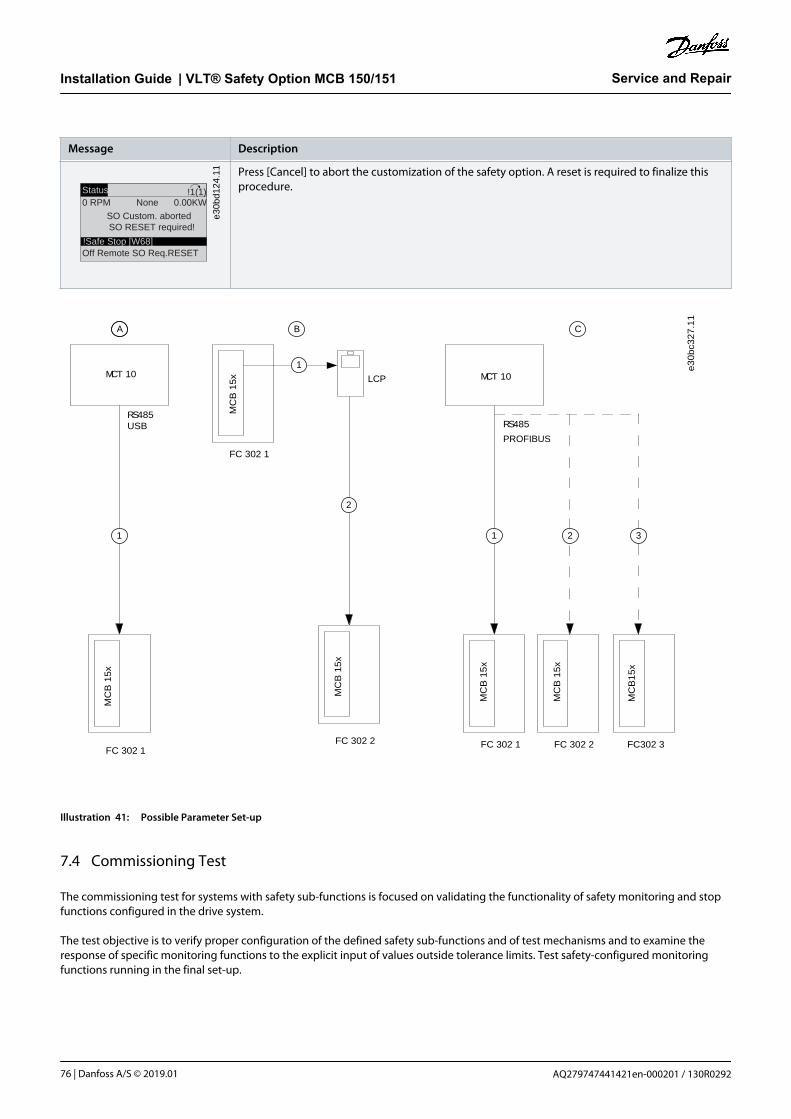
Message Description
e30b
d124
.11
Status
SO Custom. abortedSO RESET required!
!1(1)0 RPM None 0.00KW
!Safe Stop [W68]Off Remote SO Req.RESET
Press [Cancel] to abort the customization of the safety option. A reset is required to finalize thisprocedure.
e3
0b
c32
7.1
1
FC 302 1
FC 302 1
FC 302 1 FC 302 2 FC302 3 FC 302 2
MCT 10
RS485
MC
B 1
5x
MC
B 1
5x
MC
B 1
5x
MC
B 1
5x
MC
B 1
5x
MC
B1
5x
MCT 10
1 2 3
2
1
1
RS485USB
LCP
A B C
PROFIBUS
Illustration 41: Possible Parameter Set-up
7.4 Commissioning Test
The commissioning test for systems with safety sub-functions is focused on validating the functionality of safety monitoring and stopfunctions configured in the drive system.
The test objective is to verify proper configuration of the defined safety sub-functions and of test mechanisms and to examine theresponse of specific monitoring functions to the explicit input of values outside tolerance limits. Test safety-configured monitoringfunctions running in the final set-up.
Service and RepairInstallation Guide | VLT® Safety Option MCB 150/151
AQ279747441421en-000201 / 130R029276 | Danfoss A/S © 2019.01

7.4.1 Safety Guidelines
When commissioning/recommissioning, note the following:
• Secure the site in accordance with the regulations (barrier, warning signs, and more). The system may only be commissioned/recommssioned by qualified personnel.
• Refer to the information and specifications stated in the operating guide of the relevant programmable control system.
• During commissioning/recommissioning, make sure that no personal injury and/or material damage can occur, even if the plant/machine moves unintentionally.
• When commissioning the safety option, read the safety guidelines in the operating guide for the drive.
7.4.2 Before Running the Commissioning Test
The system integrator/machine manufacturer runs a commissioning test of the safety option to verify and document the correctselection of the safety option parameter values. The system integrator/machine manufacturer hereby proves to have tested theeffectiveness of the safety sub-functions used. Run the commissioning test based on the risk analysis. All applicable standards andregulations must be adhered to.
Check that:
• The machine is properly wired.
• The effectiveness of all safety components used in the application fulfills the requirements.
• All safety equipment, such as protective door monitoring devices, light barriers, or emergency stop switches, is connected andready for operation.
• All motor parameters and command parameters must be set correctly on the drive.
Run a commissioning test of the safety option in the following situations:
• After the configuration of each machine.
• After changing the safety option parameters.
• After making changes to the machine (as per applicable standards and regulations).
7.4.2.1 Checking Effectiveness of Safety Sub-functions
Procedure
1. Document each individual step of the test.
2. Note the checksum of the safety option parameters in the records.
3. Do NOT release the system unless it has successfully passed all individual steps of the test.
4. Restart the drive and check that the motor runs normally.
7.4.3 Safety Sub-functions in the Drive
After making, for example, an LCP copy of safe parameters, a commissioning test is required. Use these short versions of thecommissioning test reports to follow and approve the test sequence.
Service and RepairInstallation Guide | VLT® Safety Option MCB 150/151
AQ279747441421en-000201 / 130R0292 | 77Danfoss A/S © 2019.01

Table 18: Commissioning Test Report, Safe Torque Off
Test procedure Approved
1. Disable the STO function:
• Via DI1.
• Via DI2.
• Check the STO circuit connections against the circuit diagram.
2. No safety faults and alarms.
3. Run the drive.
4. Ensure that the correct drive is running.
5. Select STO while the drive is running.
6. Check the following:
• The drive coasts to 0 speed.
• The motor is braked and stopped by the mechanical brake (if available and configured).
• Warning/alarm 68, Safe Stop is shown.
7. Deselect STO.
8. Check the following:
• Depending on the configuration, Safety Func. Pending is shown.
9. Restart the drive and check that the motor runs normally.
10. Ensure that the STO function is safe and accepted to operate.
11. Document and sign the commissioning test report.
Table 19: Commissioning Test Report, Safe Stop 1 Time-based
Test procedure Approved
1. Disable the Safe Stop 1 function:
• Via DI1.
• Via DI2.
• Check the SS1 circuit connections against the circuit diagram.
2. No safety faults and alarms.
3. Run the drive.
4. Ensure that the correct drive is running.
5. Select SS1 while the drive is running.
6. Check the following:
• The drive ramps down to 0 speed. Ensure that it stops within the delay time specified.
• The motor is braked and stopped by the mechanical brake (if available and configured).
• The SS1 ends with an STO warning or alarm, depending on the configuration.
7. Deselect SS1.
8. Check the following:
• Safety Func. Pending is shown.
• SS1 is deselected and inactive.
Service and RepairInstallation Guide | VLT® Safety Option MCB 150/151
AQ279747441421en-000201 / 130R029278 | Danfoss A/S © 2019.01

Test procedure Approved
9. Restart the drive and check that the motor runs normally.
10. Ensure that the SS1 function is ready to operate.
11. Document and sign the commissioning test report.
Table 20: Commissioning Test Report, Safe Stop 1 Delay
Test procedure Approved
1. Disable the Safe Stop 1 function:
• Via DI1.
• Via DI2.
• Check the SS1 circuit connections against the circuit diagram.
2. No safety faults and alarms.
3. Run the drive.
4. Ensure that the correct drive is running.
5. Select SS1 Delay while the drive is running.
6. Check the following:
• The drive ramps down to 0 speed. Ensure that it stops within the delay time specified.
• The motor is braked and stopped by the mechanical brake (if available and configured).
• The SS1 ends with an STO warning or alarm, depending on the configuration.
7. Deselect SS1 Delay.
8. Check the following:
• Safety Func. Pending is shown.
• SS1 Delay is deselected and inactive.
9. Restart the drive and check that the motor runs normally.
10. Ensure that the SS1 function is ready to operate.
11. Document and sign the commissioning test report.
Table 21: Commissioning Test Report, Safe Stop 1 Ramp-based
Test procedure Approved
1. Disable the Safe Stop 1 function:
• Via DI1.
• Via DI2.
• Check the SS1 circuit connections against the circuit diagram.
2. No safety faults and alarms.
3. Run the drive.
4. Ensure that the correct drive is running.
5. Select SS1 while the drive is running.
Service and RepairInstallation Guide | VLT® Safety Option MCB 150/151
AQ279747441421en-000201 / 130R0292 | 79Danfoss A/S © 2019.01

Test procedure Approved
6. Check the following:
• The drive ramps down to 0 speed.
• The motor is braked and stopped by the mechanical brake (if available and configured).
• The SS1 ends with an STO warning or alarm, depending on the configuration.
7. Deselect SS1.
8. Check the following:
• Safety Func. Pending is shown.
• SS1 Delay is deselected and inactive.
9. Restart the drive and check that the motor runs normally.
10. Ensure that the SS1 function is ready to operate.
11. Document and sign the commissioning test report.
Table 22: Commissioning Test Report, Safely Limited Speed without Ramp
Test procedure Approved
1. Disable the SLS function:
• Via DI1.
• Via DI2.
• Check the SS1 circuit connections against the circuit diagram.
2. No safety faults and alarms.
3. Run the drive.
• Up and down ramps can be separately entered for jog operation (jog mode). This can be parameterized aspart of the Quick Menu.
• The motor speed must be higher than the SLS selected, if the machine allows this.
4. Ensure that the correct drive is running.
5. Select SLS while the drive is running.
6. Check the following:
• The drive coasts to 0 speed if STO is selected as fault reaction.
• Run SS1 if that is selected as fault reaction.
• The motor is braked and stopped by the mechanical brake (if available and configured).
• Ensure that error 70, Int fail speed limit SLSa: Reaction STO is shown.
7. Deselect SLS.
8. Check the following:
• Safety Func. Pending is shown.
• SLS is deselected and inactive.
9. Restart the drive and check that the motor runs normally.
Service and RepairInstallation Guide | VLT® Safety Option MCB 150/151
AQ279747441421en-000201 / 130R029280 | Danfoss A/S © 2019.01
Test procedure Approved
10. Ensure that the SLS function is ready to operate:
• Run motor below SLS limit.
• Activate SLS.
• Increase reference above SLS limit.
• Make sure that the SLS limit is not exceeded.
11. Document and sign the commissioning test report.
Table 23: Commissioning Test Report, Safely Limited Speed with Ramp
Test procedure Approved
1. Disable the SLS function:
• Via DI1.
• Via DI2.
• Check the SS1 circuit connections against the circuit diagram.
2. No safety faults and alarms.
3. Run the drive.
• The motor speed must be higher than the SLS selected, if the machine allows this.
4. Ensure that the correct drive is running.
5. Select SLS while the drive is running.
6. Check the following:
• The speed ramps down according to the selected ramp time/slope to SLS setpoint.
7. Deselect SLS.
8. Safety Func. Pending is shown.
9. Run the drive.
• The motor speed must be higher than the SLS selected, if the machine allows this.
10. Ensure that the correct drive is running
11. Select SLS while the drive is running.
12. Check the following:
• The drive ramps down to the SLS.
13. Deselect SLS.
14. Check the following:
• No safety faults.
• Safe Func. Pending is shown.
15. Reset the drive and check that the motor runs normally.
16. Ensure that the SLS function is ready to operate.
17. Document and sign the commissioning report.
Service and RepairInstallation Guide | VLT® Safety Option MCB 150/151
AQ279747441421en-000201 / 130R0292 | 81Danfoss A/S © 2019.01

Table 24: Commissioning Test Report, Safe Maximum Speed
Test procedure Ap-proved
1. Disable all safety sub-functions that can be activated by DI1 or DI2 and ensure that no alarms and warnings areshown.
2. Enable SMS.
3. Run the motor below SMS cut-off speed (~100 RPM below is recommended).
4. Increase the motor speed until SMS cut-off speed is reached.
5. Check that the drive coasts and Warning 68, Safe Stop is shown.
6. Set the motor speed value below SMS cut-off speed.
7. Apply reset.
8. Ensure that the motor starts running. This might require a separate start signal from the control system.
Document and sign the commissioning report.
Tester/Approver
Date:
Signature:
Service and RepairInstallation Guide | VLT® Safety Option MCB 150/151
AQ279747441421en-000201 / 130R029282 | Danfoss A/S © 2019.01

8 Warnings and Alarms
8.1 Fault Types and Messages
This chapter provides troubleshooting tables for diagnosing fault conditions associated with the safety option.
The safety option differentiates between fatal error and alarm.
Table 25: Fault Types
Faulttype
Description Effect on thesystem
Reset condition
Fatal er-ror
Severe exceptional error caused by the program run in thesafety option. Cyclic program sequence is no longer possi-ble for safety-related reasons. The last active function isshown. The system is in stop mode.
Output S37 isswitched off
Reset possible by power cycling thedrive or restart the safety option viaparameter 42-90 Restart Safe Option.
Alarm Functional fault, caused by an external process. Both sys-tems continue to run cyclically and serve all requests fromthe communication interfaces. Sensing of the externalprocess is also maintained.
Output S37 isswitched off
Reset possible via parameterizable in-put DI2, reset on LCP/DI or via field-bus or via parameter 42-90 RestartSafe Option.
Table 26: LED Status Indicators
Color Mode Description
Green Flashing System OK, configuration validated.
Green Permanent System OK, input or output activated.
Yellow Flashing System OK, configuration not yet validated.
Red Flashing Alarm.
Red Permanent Fatal error.
All external failures can be removed by giving a reset signal (via LCP, DI2a, and digital inputs on control card or via fieldbus dependingon configuration). All internal failures can be removed by power cycle, parameter 42-90 Restart Safe Option and configuration.
8.1.1 Messages
Any errors on the safety option are indicated on the drive display with different messages.
The following options are available for detailed diagnosis and fault detection:
• LEDs on the front of the safety option provide information on operating states. The LEDs are used to indicate the status of theoption, that is active safety sub-functions, failures, and warnings, if any.
• LCP text or information via bus shows the status of the safety sub-functions (for example SS1a).
The following is shown in online mode in the MCT 10 Set-up Software:
• Status of the safety option input and output errors, messages, and the corresponding remedies are shown in the expandeddiagnosis system of the MCT 10 Set-up Software.
Warnings and AlarmsInstallation Guide | VLT® Safety Option MCB 150/151
AQ279747441421en-000201 / 130R0292 | 83Danfoss A/S © 2019.01

8.2 Warnings and Alarms
N O T I C EThe errors are listed numerically.
Table 27: LED Indications, Errors 1–68
Errornum-ber
Descrip-tion
LED indicators
LED1 LED2 LED4
Internalfailure
Reason Action Greencon-stant
1 Diagnosticin pro-gress
Status of LED 1 and LED2 de-pends on safety sub-functionstate assigned to DI1 and DI2.
Greencon-stant
67 Int Fail tol-erance er-ror excee-ded: Reac-tion STO
• Check that data for feed-back (PPR., type of feed-back, and gear ratio) is en-tered correctly.
• Direction of feedback iswrong.
• Due to use of feedback fil-ter the dynamic of the sys-tem does not match withdynamic of feedback filter(parameter 42-15 FeedbackFilter). System is rampingtoo fast.
• Feedback signals are notreceived at all.
• No proper shielding offeedback cables.
• Make a recustomizationwith correct data if nee-ded.
• Set parameter 42-12 En-coder Direction to the op-posite value.
• Decrease the rampingtime on the drive.
• Try to run the system at,for example, 60 RPM. If er-ror 99, Int Fail Feedback er-ror occurs, this is the rea-son.
• Improve shielding offeedback cables and mo-tor cables.
Redcon-stant
68 Int failSpeed lim-it SS1aRamp: Re-action STO
• The value of Delta V is toosmall. For closed-loop sys-tem, it must often be larg-er than the recommendedvalue.
• Due to use of feedback fil-ter the dynamic of the sys-tem does not match withdynamic of feedback filter(parameter 42-15 FeedbackFilter).
• Load change takes placeduring ramping.
• If running in closed loop,try to adjust PID settingand if needed increaseSS1 ramping time.
• Try to increase parameter42-15 Feedback Filter, butthis might cause error 67,Int Fail tolerance error ex-ceeded: Reaction STO tooccur.
• Otherwise increase pa-rameter 42-45 Delta V.
Redcon-stant
Warnings and AlarmsInstallation Guide | VLT® Safety Option MCB 150/151
AQ279747441421en-000201 / 130R029284 | Danfoss A/S © 2019.01

Table 28: LED Indications, Errors 69–72
Errornum-ber
Description LED indicators
LED1 LED2 LED4
Internal fail-ure
Reason Action Greencon-stant
69 Int fail Speedlimit SS1bRamp: Reac-tion STO
See 68. See 68. Status of LED 1 and LED 2 dependson safety sub-function state assignedto DI1 and DI2.
Redcon-stant
70 Int fail speedlimit SLSa:Reaction STO
Happens duringramping to SLS limit,see 68.
Happens duringspeed below SLS lim-it:
• If speed is abovecut-off speed atactivation pointand parameter42-53 Start Rampis set to No, thiserror occurs.
• Noise on the feed-back signal (incl.quantizationnoise) is largerthan expected.
• Load changetakes place, do asin above point.
• Change parameter42-53 Start Ramp to Yesand set parameter42-54 Ramp Down Timeaccordingly.
• Increase parameter42-50 Cut Off Speed ordecrease parameter42-51 Speed Limit to geta larger tolerance.
Redcon-stant
71 Int fail speedlimit SLSb:Reaction STO
See 70. See 70. Redcon-stant
72 Internal fail-ure MCB150/151
• First, power cycle thedrive or restart the safe-ty option via parameter42-90 Restart Safe Op-tion. Second, try tomake a general reset ofthe safety option withthe Administration but-ton (safety option goesback to blank initialstate).
• If the problem persists,contact Danfoss.
Redcon-stant
Warnings and AlarmsInstallation Guide | VLT® Safety Option MCB 150/151
AQ279747441421en-000201 / 130R0292 | 85Danfoss A/S © 2019.01

Table 29: LED Indications, Errors 73–77
Errornum-ber
Description LED indicators
LED1 LED2 LED4
Internal fail-ure
Reason Action Greencon-stant
73 Internal fail-ure MCB150/151
• First, power cycle the drive orrestart the safety option viaparameter 42-90 Restart SafeOption.
• If the problem persists, con-tact Danfoss.
Status of LED 1 and LED 2 depends onsafety sub-function state assigned toDI1 and DI2.
Redcon-stant
74 Internal fail-ure MCB150/151
• First, power cycle the drive orrestart the safety option viaparameter 42-90 Restart SafeOption.
• If the problem persists, con-tact Danfoss.
Redcon-stant
75 Int Fail DI2 inPUST: Reac-tion STO
• Safety in-put con-nected toDI2 has ille-gal signallevel.
• Sensor isbroken.
• Check that the configurationof DI2 parameter 42-21 Type isset correctly or that the con-nected sensor is installed ac-cording to specification.
• Extend discrepancy time onthe safe input tab in the MCT10 Safe Plug-in via parameter14-22 Operation Mode.
Redcon-stant
76 Int Fail DI1 inPUST: Reac-tion STO
• Safety in-put con-nected toDI1 has ille-gal signallevel.
• Sensor isbroken.
• Check that the configurationof DI1 parameter 42-21 Type,sub-index [0], is set correctlyor that the connected sensoris installed according to spec-ification.
• Extend discrepancy time onthe safe input tab in the MCT10 Safe Plug-in via parameter14-22 Operation Mode.
Redcon-stant
77 Int Fail fail-safe dataCRC mis-match: Reac-tion STO
The CRC of thesafety optiondoes not matchthe stored CRCvalue on thedrive.
Configure the safety option withMCT 10 Safe Plug-in or by CRC se-lect/LCP copy.
Redcon-stant
Warnings and AlarmsInstallation Guide | VLT® Safety Option MCB 150/151
AQ279747441421en-000201 / 130R029286 | Danfoss A/S © 2019.01

Table 30: LED Indications, Errors 78–85
Errornum-ber
Description LED indicators
LED1 LED2 LED4
Internal fail-ure
Rea-son
Action Greenconstant
78 Internal fail-ure safety op-tion
• First, power cyclethe drive or restartthe safety optionvia parameter 42-90Restart Safe Option.
• If the problem per-sists, contact Dan-foss.
Status of LED 1 and LED 2 depends on safety sub-func-tion state assigned to DI1 and DI2.
Red con-stant
79 Internal fail-ure safety op-tion
Contact Danfoss. Red con-stant
80 Internal fail-ure safety op-tion
Contact Danfoss. Red con-stant
81 Internal fail-ure safety op-tion
• First, power cyclethe drive.
• If the problem per-sists, contact Dan-foss.
Red con-stant
82 Internal fail-ure safety op-tion
• First, power cyclethe drive.
• If the problem per-sists, contact Dan-foss.
Red con-stant
83 Internal fail-ure safety op-tion
• First, power cyclethe drive.
• If the problem per-sists, contact Dan-foss.
Red con-stant
84 Internal fail-ure safety op-tion
• First, power cyclethe drive.
• If the problem per-sists, contact Dan-foss.
Red con-stant
85 Internal fail-ure safety op-tion
• First, power cyclethe drive.
• If the problem per-sists, contact Dan-foss.
Red con-stant
Warnings and AlarmsInstallation Guide | VLT® Safety Option MCB 150/151
AQ279747441421en-000201 / 130R0292 | 87Danfoss A/S © 2019.01
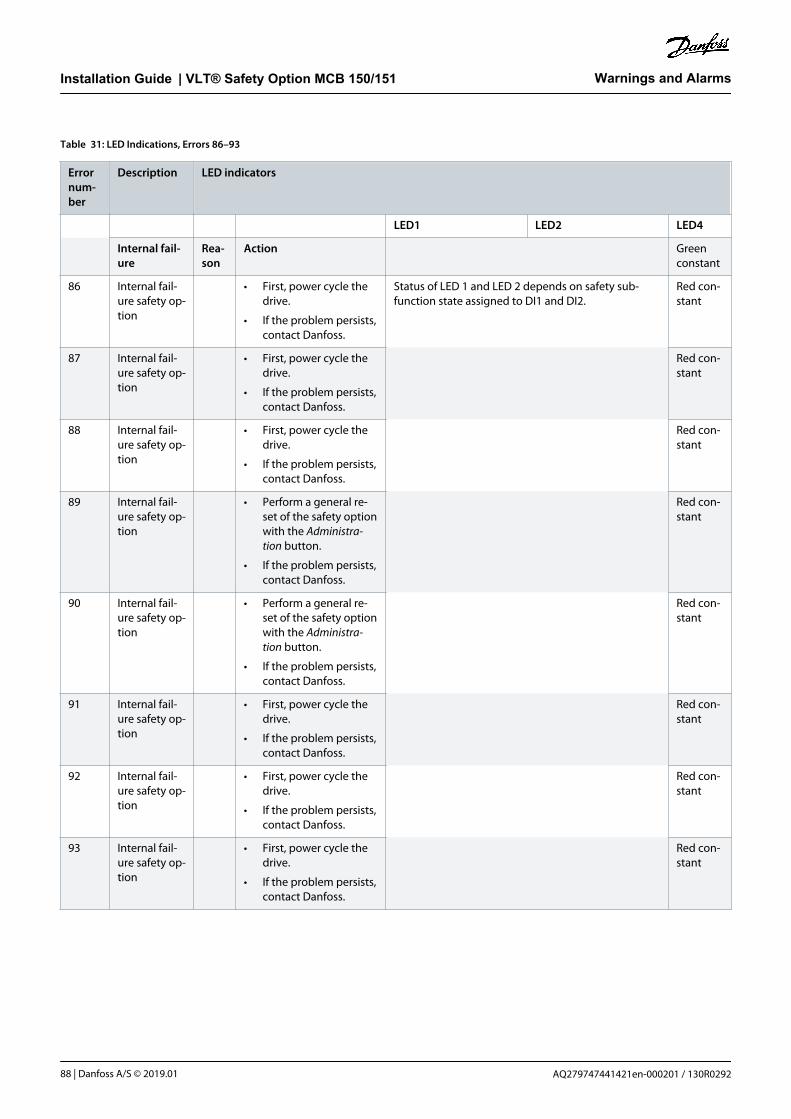
Table 31: LED Indications, Errors 86–93
Errornum-ber
Description LED indicators
LED1 LED2 LED4
Internal fail-ure
Rea-son
Action Greenconstant
86 Internal fail-ure safety op-tion
• First, power cycle thedrive.
• If the problem persists,contact Danfoss.
Status of LED 1 and LED 2 depends on safety sub-function state assigned to DI1 and DI2.
Red con-stant
87 Internal fail-ure safety op-tion
• First, power cycle thedrive.
• If the problem persists,contact Danfoss.
Red con-stant
88 Internal fail-ure safety op-tion
• First, power cycle thedrive.
• If the problem persists,contact Danfoss.
Red con-stant
89 Internal fail-ure safety op-tion
• Perform a general re-set of the safety optionwith the Administra-tion button.
• If the problem persists,contact Danfoss.
Red con-stant
90 Internal fail-ure safety op-tion
• Perform a general re-set of the safety optionwith the Administra-tion button.
• If the problem persists,contact Danfoss.
Red con-stant
91 Internal fail-ure safety op-tion
• First, power cycle thedrive.
• If the problem persists,contact Danfoss.
Red con-stant
92 Internal fail-ure safety op-tion
• First, power cycle thedrive.
• If the problem persists,contact Danfoss.
Red con-stant
93 Internal fail-ure safety op-tion
• First, power cycle thedrive.
• If the problem persists,contact Danfoss.
Red con-stant
Warnings and AlarmsInstallation Guide | VLT® Safety Option MCB 150/151
AQ279747441421en-000201 / 130R029288 | Danfoss A/S © 2019.01

Table 32: LED Indications, Errors 94–102
Errornum-ber
Description LED indicators
LED1 LED2 LED4
Internal fail-ure
Reason Action Greencon-stant
94 Internal fail-ure safetyoption
• First, power cyclethe drive.
• If the problempersists, contactDanfoss.
Status of LED 1 and LED 2 depends on safetysub-function state assigned to DI1 and DI2.
Redcon-stant
95 Internal fail-ure safetyoption
• First, power cyclethe drive.
• If the problempersists, contactDanfoss.
Redcon-stant
96 Internal fail-ure safetyoption
• First, power cyclethe drive.
• If the problempersists, contactDanfoss.
Redcon-stant
97 Internal fail-ure safetyoption
Contact Danfoss. Redcon-stant
98 Int fail inva-lid customerfile version
Version of cus-tomization file ofsafety option stor-ed in EEPROMdoes not matchthe customizationfile supported bythe SW version ofsafety option.
Do a new configura-tion with MCT 10Safe Plug-in, whichsupports the SW ver-sion of safety option.
99 Int Fail Feed-back error
The connectedfeedback sourcedoes not give anysignal.
Check that the con-nection is done ac-cording to the speci-fication or if the feed-back source is bro-ken.
Red
102 Int FailSpeed LimitSMS: Reac-tion STO
• Speed isabove cut-offspeed.
• Noise on thefeedback sig-nal (incl. quan-tization noise)is larger thanexpected.
Check the value ofparameter 42-71 CutOff Speed.
Redcon-stant
Warnings and AlarmsInstallation Guide | VLT® Safety Option MCB 150/151
AQ279747441421en-000201 / 130R0292 | 89Danfoss A/S © 2019.01

Table 33: LED Indications, Errors 113–135
Errornum-ber
Description LED indicators
LED1 LED2 LED4
Internal fail-ure
Reason Action Green con-stant
113 Ext Fail DI1:Reaction STO
• Safety inputconnected toDI1 has illegalsignal level.
• Sensor is bro-ken.
• Check that config-uration of DI1 pa-rameter 42-21 Typeis set correctly orthe connectedsensor is installedaccording to thespecification.
Red constant. Status dependson safety sub-function state as-signed to DI2.
Red flash-ing, cycle(on 500 ms,off 500 ms)
114 Ext Fail DI2:Reaction STO
• Safety inputconnected toDI2 has illegalsignal level.
• Sensor is bro-ken.
• Check that config-uration of DI2 pa-rameter 42-21 Typeis set correctly orthe connectedsensor is installedaccording to thespecification.
• Extend discrepan-cy time on safe in-put tab in MCT 10Safe Plug-in pa-rameter 14-22 Op-eration Mode.
Status dependson safety sub-function state as-signed to DI1.
Red constant. Red flash-ing, cycle(on 500 ms,off 500 ms)
115 Ext Fail PrecThresh TimerElapsed: Reac-tion STO
The drive has beenrunning below120 RPM for morethan the time en-tered in parameter42-18 Zero SpeedTimer with safefunction SLS active.
Increase speed toabove 120 RPM.
Status of LED 1 and LED 2 depends onsafety sub-function state assigned toDI1 and DI2.
Red flash-ing, cycle(on 500 ms,off 500 ms)
116 Ext Fail SF acti-vation SpeedSuspension:Reaction STO
The drive has beenrunning below120 RPM for morethat 1 year and asafety sub-functionthat needs speedfeedback is activa-ted.
Increase speed toabove 120 RPM.
Red flash-ing, cycle(on 500 ms,off 500 ms)
134 Int fail speedlimit SLSa: Re-action SS1a
See 70. See 70. Red con-stant
135 Int fail speedlimit SLSb: Re-action SS1a
See 70. See 70. Red con-stant
Warnings and AlarmsInstallation Guide | VLT® Safety Option MCB 150/151
AQ279747441421en-000201 / 130R029290 | Danfoss A/S © 2019.01

Table 34: LED Indications, Errors 177–252
Errornum-ber
Description LED indicators
LED1 LED2 LED4
Internal failure Reason Action Green constant
177 Ext Fail DI1: ReactionSS1a
See113.
See 113. Red constant. Status depends onsafety sub-functionstate assigned to DI2.
Red flashing, cy-cle (on 500 ms, off500 ms)
178 Ext Fail DI2: ReactionSS1a
See114.
See 114. Status depends onsafety sub-functionstate assigned to DI1.
Red constant. Red flashing, cy-cle (on 500 ms, off500 ms)
179 Ext Fail Prec ThreshTimer Elapsed: Reac-tion SS1a
See115.
See 115. Status of LED 1 and LED 2 depends on safetysub-function state assigned to DI1 and DI2.
Red flashing, cy-cle (on 500 ms, off500 ms)
180 Ext Fail SF activationSpeed Suspension:Reaction SS1a
See116.
See 116. Red flashing, cy-cle (on 500 ms, off500 ms)
198 Int fail speed limitSLSa: Reaction SS1b
See 70. See 70. Red constant
199 Int fail speed limitSLSb: Reaction SS1b
See 70. See 70. Red constant
241 Ext Fail DI1: ReactionSS1b
See113.
See 113. Red constant. Status depends onsafety sub-functionstate assigned to DI2.
Red flashing, cy-cle (on 500 ms, off500 ms)
242 Ext Fail DI2: ReactionSS1b
See114.
See 114. Status depends onsafety sub-functionstate assigned to DI1.
Red constant. Red flashing, cy-cle (on 500 ms, off500 ms)
243 Ext Fail Prec ThreshTimer Elapsed: Reac-tion SS1b
See115.
See 115. Red flashing, cy-cle (on 500 ms, off500 ms)
244 Ext Fail SF activationSpeed Suspension:Reaction SS1b
See116.
See 116. Red flashing, cy-cle (on 500 ms, off500 ms)
252 Internal failure safetyoption
Power cy-cle thedrive. Ifthe prob-lem per-sists, con-tact Dan-foss.
8.2.1 Safety Option Warning
A warning message notifies that an issue exists on the safety option. It is not handled as an internal or external failure. These messagesare defined to indicate that a manual user action is required.
Warnings and AlarmsInstallation Guide | VLT® Safety Option MCB 150/151
AQ279747441421en-000201 / 130R0292 | 91Danfoss A/S © 2019.01

N O T I C EAt any possible failure or warning indicated from the safety option, the LCP shows warning, !Safe Option Failure [W252] at theleast.
8.2.2 Safety Option Reset Message
For some messages, the safety option requires an acknowledgement of an ongoing action or failure on the safety option. The safetyoption uses Safe Option RESET as a Restart and Failure Acknowledgement.
Table 35: LCP Reset Messages
LCP message Description
e30b
d126
.11
S tatus
SO Reset required!
!1(1)0 R PM None 0.00 KW
!Safe S top [W68]
In the following cases, the safety option requests a restart and failure acknowledgement signal:
• The safety option is in safety sub-function pending-state (remark: Occurs only if reset behav-ior is set/configured to Manual).
• After a power cycle with a safety sub-function.
• In PUST (power up self-test), if an external failure occurred before power cycle.
• When an external failure occurred.
• When customization was aborted or completed.
• At the reception of a general reset (required after blank initial state or in the customizationstate).
e30b
d127
.11
S tatus
SO in Self-test
!1(1)0 R PM None 0.00 KW
!Safe S top [W68]
The safety option indicates that it is in PUST State (Power Up Self Test).
• Ensure that no safe function is active after a power cycle.
e30b
d127
.11
S tatus
SO in Self-test
!1(1)0 R PM None 0.00 KW
!Safe S top [W68]
A safety sub-function is pending at the start-up, if the drive was powered down while a safetyfunction was active. It is also pending, when the drive was powered down while the safety optionhas detected a failure during an active safety sub-function.
e30b
d129
.11
S tatus
SafeOpt. initialised
!1(1)0 R PM None 0.00 KW
!Safe S top [W68]
The safety option requests a Restart and Failure Acknowledge signal, which is always required af-ter a PUST and when a safety sub-function gets released and is configured to be confirmed thatthe motor is able to run.
Warnings and AlarmsInstallation Guide | VLT® Safety Option MCB 150/151
AQ279747441421en-000201 / 130R029292 | Danfoss A/S © 2019.01

LCP message Description
e30b
d130
.11
S tatus
SO General Reset
!1(1)0 R PM None 0.00 KW
!Safe S top [W68]
Occurs only if general reset is performed from MCT 10. It is an indication to the user. The safetyoption is set to blank initial state and safe parameters are set to default.
e30b
d131
.11
S tatus
SO Suspend-SpeedMon
!1(1)0 R PM None 0.00 KW
!Safe S top [W68]
Zero speed timer contains the remaining time until the fail prec thresh timer elapsed after themonitoring time expires. The safety option signals Warning.
e30b
d132
.11
S tatus
SO Warning PUST
!1(1)0 R PM None 0.00 KW
!Safe S top [W68]
PUST warning has occurred. Warning cause: Expiry of PUST timer. Memory test required, performpower cycle.
e30b
d133
.11
S tatus
SO Warning DI1
!1(1)0 R PM None 0.00 KW
!Safe S top [W68]
DI1 offline warning has occurred. Warning cause: Expiry of offline timer for DI1.
e30b
d134
.11
S tatus
SO Warning DI2
!1(1)0 R PM None 0.00 KW
!Safe S top [W68]
DI2 offline warning has occurred. Warning cause: Expiry of offline timer for DI2.
e30b
d131
.11
S tatus
SO Suspend-SpeedMon
!1(1)0 R PM None 0.00 KW
!Safe S top [W68]
Speed monitoring suspension warning has occurred. Warning cause: Suspension of speed moni-toring for a certain duration.
Warnings and AlarmsInstallation Guide | VLT® Safety Option MCB 150/151
AQ279747441421en-000201 / 130R0292 | 93Danfoss A/S © 2019.01

9 Technical Specifications
9.1 Consumption
Power consumption 2 W (equivalent power consumption related to VDD)
Current consumption VCC (5 V) <200 mA
Current consumption VDD (24 V) <30 mA (<25 mA for VLT® Safety Option MCB 150)
9.2 Inputs
9.2.1 Digital Inputs
Number of digital inputs 4 (2x2-channel digital safety input)
Input voltage range 0–24 V DC
Input voltage range, logic 0 <5 V DC
Input voltage range, logic 1 >12 V DC
Input voltage (maximum) 28 V DC
Input current (minimum) 6 mA @Vin=24 V (inrush current 12 mA peak)
Input resistance Approximately 4 kΩ
Galvanic isolation No
Short-circuit proof Yes
Input pulse recognition time (minimum) 3 ms
Discrepancy time 9 ms
Cable length <30 m (98.4 ft) (shielded or unshielded cable), >30 m (98.4 ft) (shielded cable)
9.2.2 TTL Encoder Input (VLT® Safety Option MCB 150)
Number of encoder inputs 4 (2 x differential inputs A, A/; B,/B)
Encoder types TTL, RS422/RS485 incremental encoders
Input differential voltage range -7 to +12 V DC
Input common-mode voltage -12 to +12 V DC
Input voltage, logic 0 (differential) <-200 mV DC
Input voltage, logic 1 (differential) >+200 mV DC
Input resistance Approximately 120 Ω
Maximum frequency 410 kHz
Short-circuit proof Yes
Cable length <150 m (492 ft) (tested with shielded cable - Heidenhain AWM Style 20963 80 °C 30V E63216, 100 m(328 ft) shielded motor cable, no load on motor)
9.2.3 HTL Encoder Input (VLT® Safety Option MCB 151)
Number of encoder inputs 2 (2 x single ended inputs A; B)
Encoder types HTL incremental encoders, HTL proximity sensor, VLT® Sensorless Safety MCB 159
Technical SpecificationsInstallation Guide | VLT® Safety Option MCB 150/151
AQ279747441421en-000201 / 130R029294 | Danfoss A/S © 2019.01

Logic input PNP
Input voltage range 0–24 V DC
Input voltage, logic 0 <5 V DC
Input voltage, logic 1 >12 V DC
Input voltage (maximum) 28 V DC
Input resistance Approximately 4 Ω
Maximum frequency 110 kHz
Short-circuit proof Yes
Cable length <100 m (328 ft) (tested with shielded cable - Heidenhain AWM Style 20963 80 °C 30V E63216, 100 m (328 ft)shielded motor cable, no load on motor)
9.3 Outputs
9.3.1 Digital Output (Safe Output)
Number of outputs 1
Output voltage low <2 V DC
Output voltage high >19.5 V DC
Output voltage (maximum) 24.5 V DC
Nominal output current (@24 V) <100 mA
Nominal output current (@0 V) <0.5 mA
Galvanic isolation No
Diagnostic test pulse 300 µs
Short-circuit proof Yes
Cable length <30 m (98.4 ft) (shielded cable)
9.3.2 24 V Supply Output
Supply voltage 24 V DC (voltage tolerance: +0.5 V DC to -4.5 V DC)
Maximum output current 150 mA
Short-circuit proof Yes
Cable length <30 m (98.4 ft) (shielded or unshielded cable), >30 m (98.4 ft) (shielded cable)
9.4 Other Specifications
9.4.1 Ground I/O Section
Cable length <30 m (98.4 ft) (shielded or unshielded cable), >30 m (98.4 ft) (shielded cable)
9.4.2 Cable Cross-sections
Digital inputs/output supply voltage 0.75 mm2/18 AWG, AEH without plastic collar in accordance with DIN 46228/1
Technical SpecificationsInstallation Guide | VLT® Safety Option MCB 150/151
AQ279747441421en-000201 / 130R0292 | 95Danfoss A/S © 2019.01

9.4.3 Reset Characteristics
Manual reset time ≤5 ms (safety option), ≤5 ms (drive), ≤10 ms (fieldbus)
Manual reset pulse time 10 µs (safety option and drive)
Automatic reset time ≤4 ms
Start-up reset time ≤5 s (parameter 42-90 Restart Safe Option)
9.4.4 Response Time
Input to output response time ≤2 ms
Emergency stop until beginning of SS1/SLS ≤7 ms
Cross fault detection time ≤3 ms (@activated output)
9.4.5 Safety Characteristic Data
N O T I C EThe safety-related characteristic data are valid for all safety sub-functions. All units used within a safety sub-function must beconsidered when calculating the safety characteristic data.
Table 36: European Directives
Name of directive Number/Description
Machinery Directive (2006/42/EC) EN ISO 13849-1
EN IEC 62061
EN IEC 61800-5-2
EMC Directive (2014/30/EU) EN 50011
EN 61000-6-3
EN 61800-3
Low Voltage Directive (2014/35/EC) EN 50178
EN 61800-5-1
Table 37: Safety Standards
Name of standard Number/description
Safety of Machinery EN ISO 13849-1
IEC 62061
IEC 60204-1
Functional Safety IEC 61508-1 to -7
IEC 61800-5-2
Technical SpecificationsInstallation Guide | VLT® Safety Option MCB 150/151
AQ279747441421en-000201 / 130R029296 | Danfoss A/S © 2019.01

Table 38: Safety Sub-function
IEC 61800-5-2 IEC 60204-1
Safe Torque Off (STO) Stop Category 0
Safe Stop 1 (SS1) Stop Category 1
Safely Limited Speed (SLS) –
Table 39: Safety Performance
Name of performance Type/description
Safety Integrity Level SIL 2
SIL CL2
HFT (IEC 61508) Hardware Fault Tolerance = 1
Subsystem classification Type B
Probability of dangerous failure per hour PFH: 1,52 e-8
Probability of dangerous failure on demand PFD: 1,33 e-3
Category Cat 3
Performance level PL d (cat 3)
Mean time to dangerous failure of each channel MTTFd: 245 years (High)
Average diagnostic coverage DCave: 86% (Low)
Safe failure fraction SFF: 90%
Proof test interval 20 years
Technical SpecificationsInstallation Guide | VLT® Safety Option MCB 150/151
AQ279747441421en-000201 / 130R0292 | 97Danfoss A/S © 2019.01

10 Appendix
10.1 Abbreviations
Abbreviation Description
Cat. Category (EN ISO 13849-1).
CCF Common cause failure (IEC 61508, IEC 62061, EN 61511-1, EN ISO 13849-1).
CCW Counterclockwise.
CW Clockwise.
DC Diagnostic coverage (EN ISO 13849-1, IEC 62061 (IEC61508-2)).
DIx DI1: Digital input 1.
DI2: Digital input 2.
EMC Electromagnetic compatibility.
MFFT/MTTFd Mean time to failure/mean time to dangerous failure (EN ISO 13849-1).
OSSD Output signal switching device (EN 61496-1).
PDS(SR) Power drive system (safety related).
PELV Protective extra low voltage, low voltage with isolation. For more information: IEC 60364-4-41 or IEC 60204-1.
PFD Probability of failure on demand (IEC 61508, IEC 62061).
PFH Probability of failure per hour (IEC 61508, IEC 62061).
PLC Programmable logic controller.
PUST Power up self-test. Internal self-test on the safety option.
SF Safe function.
SIL Safety integrity level (IEC 61508, IEC 61800-5-2, IEC 62061).
SLS Safely Limited Speed.
SO Safety option.
SRECS Safety-related electrical control system (IEC 62061).
SRP/CS Safety-related part of control systems (EN ISO 13849-1).
SS1 Safe stop 1.
STO Safe Torque Off.
TM Mission time (EN ISO 13849-1).
AppendixInstallation Guide | VLT® Safety Option MCB 150/151
AQ279747441421en-000201 / 130R029298 | Danfoss A/S © 2019.01

10.2 Conventions
• Numbered lists indicate procedures.
• Bulleted and dashed lists indicate listings of other information where the order of the information is not relevant.
• Bolded text indicates highlighting and section headings.
• Italicized text indicates the following:
- Cross-reference.
- Link.
- Footnote.
- Parameter name.
- Parameter option.
- Parameter group name.
• All dimensions in drawings are in metric values (imperial values in brackets).
• An asterisk (*) indicates the default setting of a parameter.
AppendixInstallation Guide | VLT® Safety Option MCB 150/151
AQ279747441421en-000201 / 130R0292 | 99Danfoss A/S © 2019.01

Index
AApprovals and certifications 8
Available resources 7
BBraking ramp 18, 23, 25, 25, 29, 36, 58
CCable cross-section 95
Cable length 94, 95
Cable length, encoder 45
Category 0 stop 20, 21
Category 1 Stop 20
Commissioning software 58
Commissioning test 36, 58, 72
Configuration 18, 58
Configuration, s-ramp 24
Continuous mode 18
Conventions 99
Cross-section 45
DDigital input 19, 28, 30, 32, 33, 33, 94
Digital input, connecting 50
Digital output 95
Discrepancy 33, 66
EEN ISO 12100 10
Encoder 20, 25, 27, 36, 45
Encoder input 94, 94
Encoder, configuration 58
Error response 29, 31
FFeedback source 56, 89
HHigh voltage 10
High-demand mode 18
HTL 13
HTL encoder 20, 36, 45
LLEDs 19, 84
Load sharing 10
Low-demand mode 18
MMCT 10 Safe Plug-in 21, 54, 54, 58, 86
OOption change 71
Output 95
PPassword 72
Password, reset 60
PFD definition 18
PFH definition 18
PNP proximity switch 20, 36
Power consumption 94
Priority 16
Purpose of the manual 7
QQualified personnel 7, 10
RRamp 16
Reset 32, 36
Reset characteristics 96
Reset condition 83
Reset function 19, 33
Reset password 60
Reset signal 33, 83
Response time 34, 34, 96
Risk assessment 15
RS485 46, 53, 58, 72
SS-ramp 24
S37 32
Safe jog 29
Safe maximum speed 19, 59
IndexInstallation Guide | VLT® Safety Option MCB 150/151
AQ279747441421en-000201 / 130R0292100 | Danfoss A/S © 2019.01

Safe motion monitoring 18
Safe output 95
Safe speed monitoring 19
Safe stop 1 13, 16, 20, 22, 23, 25, 32, 59
Safe Torque Off 13, 16, 20, 21, 23, 32, 35
Safely limited speed 16, 21, 27, 29, 32, 59
Safety control system 14, 16
Safety sensor 19, 33
Safety sub-function 15, 18, 20, 21, 23, 32, 33, 54, 59
Sensor 33
Signal 13, 21, 32, 34, 45, 59
Signal, reset 83
SLS 27, 29, 32, 90
SMS 19
See Safe maximum speed
SS1 32
SS1 delay 22
SS1 ramp 28, 84
Status indicator 19, 83
STO 20, 28, 32, 32, 84
Supply voltage 19, 45
Symbols 9
TTest 35
Test pulse pattern 34
Thermal protection 8
TTL 13
TTL encoder 20, 36, 45
UUL certification 8
USB 54, 58, 72
VVLT Sensorless Safety MCB 159 option 36
IndexInstallation Guide | VLT® Safety Option MCB 150/151
AQ279747441421en-000201 / 130R0292 | 101Danfoss A/S © 2019.01

Glossary - VLT® Safety Option MCB 150/151
BBlank initial state Factory settings
DDegree of protection The degree of protection is a standardized specification for electrical equip-
ment that describes the protection against the ingress of foreign objects
and water (for example, IP20).
EEncoder Sensor for detection of the angular position of a rotating component. In-
stalled on/in a motor, the encoder shows the angular position of the rotor.
Error Discrepancy between a computed, observed, or measured value or condi-
tion and the specified or theoretically correct value or condition.
Error class Classification of errors into groups. The different error classes allow for spe-
cific responses to errors, for example by severity.
FFactory settings Factory settings when the product is shipped.
Fatal error If a fatal error occurs, the product is no longer able to control the motor so
that the power stage must be immediately disabled.
Fault Fault is a state that can be caused by an error.
Fault reset A function used to restore the drive to an operational state after a detected
error is cleared by removing the cause of the error so that the error is no
longer active.
PParameter Device data and values that can be read and set (to a certain extent) by the
user.
PL/Performance level Discrete level used to specify the ability of safety-related parts of control
systems to perform a safety sub-function under foreseeable conditions (EN
ISO 13849-1).
RRS485 Fieldbus interface as per EIA-422/485 Bus Description, which enables serial
data transmission with multiple devices.
SSafe state If a safe state fault is detected, the safety option goes into safe state. This
includes faults related to integrity of hardware and firmware.
Glossary - VLT® Safety Option MCB150/151Installation Guide | VLT® Safety Option MCB 150/151
AQ279747441421en-000201 / 130R0292102 | Danfoss A/S © 2019.01

SLS - Safely limited speed Safety sub-function in accordance with EN IEC 61800-5-2, monitors the
drive to check that it stays within a defined speed limit.
SMS - Safe maximum speed In accordance with EN IEC 61800-5-2, the safety sub-function monitors the
drive continuously to check that it stays within a defined speed limit.
SS1 - Safe stop 1 Safety sub-function in accordance with EN IEC 61800-5-2, ensures that the
motor decelerates in the expected way.
STO - Safe Torque Off Safety sub-function in accordance with EN IEC 61800-5-2, prevents torque
from being generated by the motor. This function is integrated within the
drive as a standard.
WWarning If the term is used outside the context of safety instructions, a warning
alerts to a potential problem that was detected by a monitoring function. A
warning is not an error and does not cause a transition of the operating
state.
Glossary - VLT® Safety Option MCB150/151Installation Guide | VLT® Safety Option MCB 150/151
AQ279747441421en-000201 / 130R0292 | 103Danfoss A/S © 2019.01

Danfoss can accept no responsibility for possible errors in catalogues, brochures and other printed material. Danfoss reserves the right to alter its products without notice. This also applies to productsalready on order provided that such alterations can be made without subsequential changes being necessary in specifications already agreed. All trademarks in this material are property of the respectivecompanies. Danfoss and the Danfoss logotype are trademarks of Danfoss A/S. All rights reserved.
Danfoss A/SUlsnaes 1DK-6300 Graastenvlt-drives.danfoss.com
Danfoss A/S © 2019.01 MG34W502 *MG34W502* AQ279747441421en-000201/ 130R0292