vlsi test intro - utah eceece.utah.edu/~kalla/ece6745/vlsi_test_intro.pdf · agenda for today •...
TRANSCRIPT

ECE/CS 5710/6710 Digital VLSI Design
Guest Lecture
Introduction to VLSI Testing
Prof. Priyank Kalla
1
Agenda for Today
• Introduction to VLSI Testing
• Why bother? Or who cares?
– Not just Pentium Bug!
• Design versus Testing
• Testing versus Verification
• Testing Problems: where to they come from?
• Test Apps: gate-level, ckt-level, comb./seq., memory...
• Design-for-Testability, Synthesis-for-Testability
2

VLSI Circuit Realization Process
• Customer’s requirements
• Design Conceptualization by customers and designers
• Design Specifications (usually in English)
• Design Descriptions - VHDL, Verilog, SystemC, . . .
• Circuit realization: Synthesis, Custom Design
• Marketing.....
• Where do Test and Verification fit-in?
• Validation v/s Verification v/s Testing
3

VLSI Circuit Realization Process
Fabricated ICs
Manufacturing Process
Mask−level Layout
Physical SynthesisTools
Mapped Netlist
Technology Mapping
Optimized Logic Netlist
Logic OptimizationTools
Un−optimized Logic
RTL Description
CellLibrary
Translation Tools(HDL Compilers)
4

Design Validation
• Is the specification fool-proof?
– Bugs: mis-understanding, incorrect modeling, oversight...
– How to ascertain validity of the specs?
– Simulate (randomly?) and observe ... too slow
– Mathematically infer validity..... computationally infeasible
– Not everyone knows/likes “math”
– Today’s solutions: little-bit of math + little-bit of
simulation + little-bit of luck!
• Topics on design validation: Simulation, coverage metrics,
property verification, model checking, among others..
5

Enhancing the Power of Simulation
Module input ports, output ports, internal signal declarations; begin description . . . . if (condition) then assign signal = function(); end if; . . . . end description
Generate the simulation vectors to excite this statement!
Was this if−then statement coveredby simulation vectors?
Unr
oll t
he lo
gic
Figure 1: Enhancing RTL code coverage.
6
Formal Design Verification
• Simulation is incomplete - Remember Pentium Bug?
• Mathematicians say: “Mathematically prove that your system
is fool-proof!”
• Theorem Proving and Model Checking.....
• Problem: Computationally infeasible, difficult to automate
• While mathematicians argue, industry simulates.....
• Proof of equivalence is (somewhat) manageable
• Implementation Verification via Equivalence Checking.
7

Verification: Equivalence Checking
Fabricated ICs
Manufacturing Process
Mask−level Layout
Physical SynthesisTools
Optimized Logic Netlist
Logic Optimization
Un−optimized Logic
RTL Description
Translation Tools(HDL Compilers)
and Mapping Tools
Design−for−TestModifications
Testability Enhanced Netlist
RTL−to−Gate levelEquivalence Verification
Pre− and Post−Test SynthesisEquivalence Verification
Layout Verification
8

Equivalence Checking Examples
module verify(a, b, c, f, y, X, Z, F)
input a, b, c; // Boolean
input [3:0] X; // Bit-vectors
output f, y;
output [3:0] F, Z;
assign f = a’bc + ab’c + abc’ + abc;
assign y = ab + ac + bc; // a(b+c) + bc
assign F[3:0] = 8 * X[3:0] * X[3:0] + 8* X[3:0];
assign Z[3:0] = 4’b0000;
9

VLSI Testing
• Testing a fabricated chip for manufacturing defects.
• Physical Failures and Fabrication Defects due to:
• Shorts or opens on wires.... unreliable metalization
• Electromigration over a period of time
• Shorts (fusing) of Source-Drain
• Improper ion-implantation... slow switching
• Ever heard of latch-up?
• Reliability of a manufacturing process in general
10

VLSI Testing
• What is testing?
– Examine a product
– Ensure correct operation
– Exhibits the properties that it was designed for
• Detect malfunction and incorrect behaviour
• What if malfunction exists? Diagnose it.... (not testing)
• In VLSI domain, testing has a lot of secondary applications
– Reliability measurement of both, the product and the
process
– Quality assurance
– Can help in verification + validation
11

Automatic Test Equipment & Test Environment
Test
UUT
ControllerTest
LogError Fault-Free
Response
UUT’sResponse
Comparator
ReportError
InterfaceTest
Vectors
Fault-FreeUnit
(Model)
12

What to Test for and How?
• Defects, Errors and Faults....
• Design Errors, fabrication defects, physical defects
• Design errors: Specification? Logical? Design rule violation?
• Fabrication defects: shorts, opens, incorrect wiring, improper
ion-implantation, poor oxidation...
• Physical failures: Electromigration, latch-up, wear-out due to
heat/humidity/vibrations...
• Types of Testing:
– Functional Testing (Validation) and Verification
– Characterization tests on first-pass Silicon
– Production Tests: acceptance and rejection of product
– Burn-in tests: “Burn it at high speed”; detect freak-errors
13

Logical Modeling of Physical Failures
• Physical failures → anything can fail anywhere
• “Impossible” to detect physical failures on SoC/SoS
• Model physical failures as logical faults (abstract unnecessary
info)
• Logical fault model defined w.r.t. circuit structure (netlists)
• Requirement: Model should be versatile!
• Examples: Stuck-at model, bridging model, delay fault
model.... (no model at all?)
• Other defects: Delay, Transistor (stuck-open), universal,
functional, bridging....
• Overall Strategy: One-by-one, Test the chip w.r.t. each fault
model
14

“Stuck-at” Fault Model
• Borrowed from 1960’s technology, hence appealing!
• Wire w short to ground: s-a-0 or power: s-a-1
• Shorts and opens in CMOS v/s TTL (floating v/s pull-up)
• Some s-a-0/1 can cover bridging, transistor or other faults
• Multiple versus Single Stuck-at faults
Open Stuck
TTL
Multiple-stuck lines
CMOS
Poly-MetalFuse?
15
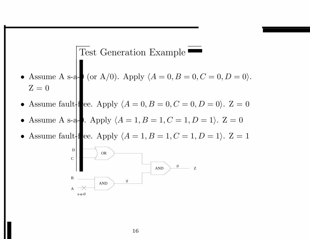
Test Generation Example
• Assume A s-a-0 (or A/0). Apply 〈A = 0, B = 0, C = 0, D = 0〉.
Z = 0
• Assume fault-free. Apply 〈A = 0, B = 0, C = 0, D = 0〉. Z = 0
• Assume A s-a-0. Apply 〈A = 1, B = 1, C = 1, D = 1〉. Z = 0
• Assume fault-free. Apply 〈A = 1, B = 1, C = 1, D = 1〉. Z = 1
OR
A
B
D
s-a-0
AND
AND
0
0 Z
C
16

Test Generation v/s Equivalence Check
• Find “Input values” → XOR output = 1
• If successful → test found
• If not? Complicated...
In 1
In 2 Fault−FreeCkt
s−a−1
1
17

Issues in Test Generation
• Test for b/1
• a = 1, b = 0, c = 1
a
b
c
zg
h
b/1
0
1
c
1/0
1/0
1/0
18

Untestable Fault
• Test for e/1: No Test...
• Faulty Circuit = Fault-Free Circuit!
a
b zg
h
1
c
???
1
1
e/10
19

Redundancy Creates Testing Problems
a
b zg
h
c
z = !a + !b + !b + !c = !a + !b + !c
20

How to test for Single Stuck-Faults
• Any and all lines can be faulty....
• Using the “computer” representation of your circuit:
• Pick a line, assume it has s-a-0 fault, derive a test that detects
that fault
• Take the same line, assume it has s-a-1 fault, derive a test for it
• One by one, go through each line, derive both tests for it
• Collect a set of “test vectors” and apply them as test stimulus,
using ATE, to the fabricated chip.
• n lines in a ckt. → 3n − 1 faults. Test for everything?
• Issues: Testing Cost, Testing Efficiency, Testing Coverage.....
• How to reduce Test Generation Effort?
21

Sequential Circuit
In Out
Yy NSPS DQ
Comb. Logic
22

Sequential Circuit Testing
Fault−Free
Faulty
In
In
Out
Out
Yy
Yy
23

Sequential Circuit Testing Example
0/1
1/1
y10/0
1/0
0/0
1/0
0/0
10
11
01
00
y2
Y1
Z
y2
y1
x
Y2
a/01/0
• Reset state: (00). Start in (00), and traverse the machine
until...
• : x0 = 1, x1 = 1, x2 = 0, x3 = 1
24

Untestable faults due to unreachable states
-/1
0/1
0/0
Y2 = y1’x + y1 y2’
Y1 = y1 y2 +y1’ y2’ x’
1/1
01 11
-/1
1000a/0
X
Y2
Y1
y2’y1
xy1’
y2y1x
y2y1
25

Logic Synthesis can cause Testing Problems
r2
r3
r1
o4
o3
o2
o1
i5
i4
i3
i2
i1
• Input i3 to output o2 cannot be “sensitized”
• Multi-Cycle “False Path”
• “Synthesize” circuit to make it easily testable!
26
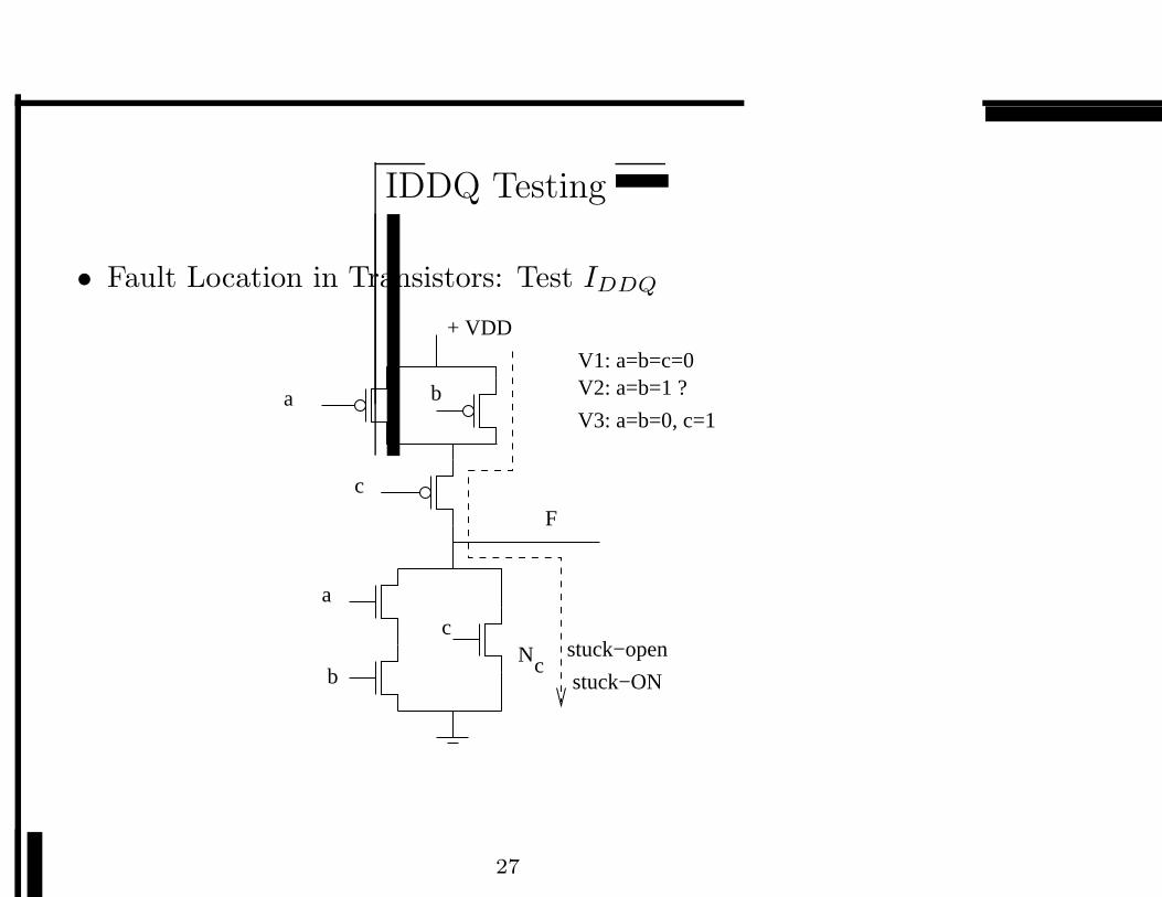
IDDQ Testing
• Fault Location in Transistors: Test IDDQ
a b
c
a
b
cN stuck−open
c
F
+ VDD
stuck−ON
V1: a=b=c=0V2: a=b=1 ?
V3: a=b=0, c=1
27

Delay-Fault Testing
• Gates do not switch at desired speed
• Find vectors that detect delay faults!
a
b
c
V1: <111>V2: <101>
1
1
slow
28

Conclusion
• CAD Tools for Testing
• Test Generation, Test Application, Power issues in Testing,
Test Time, Test Efficiency, Test Planning and Management
• TetraMax (Synopsys), HITEC, Mentor Graphics..
• Well Studied Problems, Good solutions
• Testing headache will always remain
• Courses:
– ECE/CS 5740/6740: CAD of Digital Circuits, S’08
– ECE/CS 5745/6745: Test & Verif. Digital Circuits, F’08
29