viviluxtm high luminous flux density warm white cri90 … · 1. beam angle is defined as the full...
TRANSCRIPT

LED Engin | 651 River Oaks Parkway | San Jose, CA 95134 USA | ph +1 408 922 7200 | fax +1 408 922 0158 | em [email protected] | www.ledengin.com
LZC-x0WHyy (11/06/12)
ViviLuxTM High Luminous Flux Density Warm White CRI90 LED Emitter + Lens Kit
LZC-x0WHyy Key Features
Emitter and TIR Lens Combination to meet lighting grade lux and efficacy in down lighting and accent lighting
applications
o High Luminous Flux Density 12-die Warm White Emitter
o Range of Beam options: 24o / 35o / 45o
CRI > 90 and R9> 80 for accurate color rendition
Specified at realistic lamp system operating temperatures of Tj=100oC; equivalent to Tcase of 65oC
100 lm/W typical luminous efficacy emitter only at 350mA and Tj=100oC; >85 lm/W including lens
2000 lm typical emitter only at Tj=100oC; 1700 lumens including TIR lens
Single 2.5 MacAdams Ellipses CCT bins at 2700K and 3000K color temperatures for consistent white color
100W Halogen / 35W Metal Halide replacement light source
Compact 9.0mm x 9.0mm footprint
Very low Thermal Resistance (0.7°C/W)
Based on LuxiGen LZC-series 12-die high power density product platform
Emitter available with several MCPCB options
Typical Applications
Down lighting
Accent lighting
Hospitality lighting
General lighting
Architectural lighting
Stage and Studio lighting
Description ViviLux delivers bold, vivid, and energy-efficient Lux-on-TargetTM directional lighting for retail and commercial lighting. The powerful, yet compact emitter and lens combinations lead the industry in terms of ‘lux efficacy’ or lux/Watt. Under steady-state, real world conditions of Tj=100oC, ViviLux produces 1700 lumens at 700mA after the secondary lens. This equates to an emitter luminous efficacy of 100 lumens/Watt at 350mA; Tj=100oC. With a high color rendering index (CRI), ViviLux ensures accurate color rendition in even the most demanding applications. Furthermore, emitter-to-emitter variations of less than 2.5 MacAdam Ellipses guarantee lighting consistency. ViviLux, which is based on LED Engin’s proven LuxiGen™ emitter technology, is available in three beam options: 24°/ 35°/45°, providing flexibility and freedom in lighting design.

2
LZC-x0WHyy (11/06/12)
LED Engin | 651 River Oaks Parkway | San Jose, CA 95134 USA | ph +1 408 922 7200 | fax +1 408 922 0158 | em [email protected] | www.ledengin.com
Part number options ViviLux Kits are identified by the ViviLux Kit part number; an integration of emitter and lens options. Component parts will also have sub- part number for reference. ViviLux Part Numbers
Part number Description
LZC-x0WHNF-0H27 LZC ViviLux emitter with Narrow Flood (24o) Lens and Holder; 2700K
LZC-x0WHFL-0H27 LZC ViviLux emitter with Flood (35o) Lens and Holder; 2700K
LZC-x0WHWF-0H27 LZC ViviLux emitter with Wide Flood (45o) Lens and Holder; 2700K
LZC-x0WHNF-0H30 LZC ViviLux emitter with Narrow Flood (24o) Lens and Holder; 3000K
LZC-x0WHFL-0H30 LZC ViviLux emitter with Flood (35o) Lens and Holder; 3000K
LZC-x0WHWF-0H30 LZC ViviLux emitter with Wide Flood (45o) Lens and Holder; 3000K
MCPCB Mounting Options
Part number Description
LZC-0xxxxx LZC emitter and TIR lens without MCPCB
LZC-7xxxxx LZC emitter on 1 channel 1x12 Star MCPCB
LZC-Cxxxxx LZC emitter on 2 channel 2x6 Star MCPCB
LZC-Exxxxx LZC emitter on 1 channel 1x12 Connectorized MCPCB
LZC-Fxxxxx LZC emitter on 1 channel 2x6 parallel / serial Connectorized MCPCB

3
LZC-x0WHyy (11/06/12)
LED Engin | 651 River Oaks Parkway | San Jose, CA 95134 USA | ph +1 408 922 7200 | fax +1 408 922 0158 | em [email protected] | www.ledengin.com
Warm White Chromaticity Bins @ Tj=100°C 2.5 MacAdam Ellipse Single Bins
Standard Chromaticity Groups plotted on excerpt from the CIE 1931 (2°) x-y Chromaticity Diagram. Bin coordinates are listed below in the table.
Warm White Bin Coordinates @ Tj=100°C 2.5 MacAdam Ellipse Single Bins
Bin code CIEx CIEy Bin code CIEx CIEy
27
0.4508 0.4032
30
0.4272 0.3955 0.4566 0.4152 0.4324 0.4082 0.4652 0.4168 0.4408 0.4102 0.4593 0.4048 0.4358 0.3983
0.38
0.39
0.40
0.41
0.42
0.43
0.44
0.45
0.46
0.40 0.41 0.42 0.43 0.44 0.45 0.46 0.47 0.48 0.49 0.50 0.51
Cy
Cx
Bin code 30
Bin Code 27

4
LZC-x0WHyy (11/06/12)
LED Engin | 651 River Oaks Parkway | San Jose, CA 95134 USA | ph +1 408 922 7200 | fax +1 408 922 0158 | em [email protected] | www.ledengin.com
Luminous Flux Bins – Emitter Only @ Tj=100°C
Table 1:
Bin Code
Minimum Luminous Flux (ΦV)
@ IF = 700mA [1,2]
(lm)
Maximum Luminous Flux (ΦV)
@ IF = 700mA [1,2]
(lm)
Z 1,696 2,120
C2 2,120 2,350
Notes for Table 1: 1. Luminous flux performance guaranteed within published operating conditions. LED Engin maintains a tolerance of
± 10% on flux measurements. 2. Luminous Flux typical value is for all 12 LED dice operating concurrently at rated current and temperature.
Forward Voltage Range per String @ Tj=100°C
Table 2:
Bin
Code
Minimum Forward Voltage (VF)
@ IF = 700mA [1,2]
(V)
Maximum Forward Voltage (VF)
@ IF = 700mA [1,2]
(V)
0 16.5 19.5
Notes for Table 2: 1. LED Engin maintains a tolerance of ± 0.48V for forward voltage measurements. 2. Forward Voltage is tested with 6 LED dice connected in series. The actual LED is configured with two strings of 6 dice in series.

5
LZC-x0WHyy (11/06/12)
LED Engin | 651 River Oaks Parkway | San Jose, CA 95134 USA | ph +1 408 922 7200 | fax +1 408 922 0158 | em [email protected] | www.ledengin.com
Absolute Maximum Ratings
Table 3:
Parameter Symbol Value Unit
DC Forward Current at Tjmax=130C [1] IF 1000 mA
Peak Pulsed Forward Current [2] IFP 1000 mA
Reverse Voltage VR See Note 3 V Storage / Operating Temperature Range - Lens Tstg -40 ~ +110 °C
Storage Temperature Range - Emitter Tstg -40 ~ +150 °C Junction Temperature TJ 150 °C
Soldering Temperature [4] Tsol 260 °C
Allowable Reflow Cycles 6
ESD Sensitivity [5] > 8,000 V HBM
Class 3B JESD22-A114-D
Notes for Table 3: 1. Maximum DC forward current (per die) may result in CCT being outside single bin if Tj exceeds 100oC
Follow the curves in Figure 11 for setting current such that Tj=100oC. 2: Pulse forward current conditions: Pulse Width ≤ 10msec and Duty cycle ≤ 10%. 3. LEDs are not designed to be reverse biased. 4. Solder conditions per JEDEC 020D. See Reflow Soldering Profile Figure 5. 5. LedEngin recommends taking reasonable precautions towards possible ESD damages and handling the LZ4-00CW40
in an electrostatic protected area (EPA). An EPA may be adequately protected by ESD controls as outlined in ANSI/ESD S6.1.
Optical Characteristics @ Tj=100°C
Table 4:
Parameter Symbol Typical Unit
Luminous Flux - kit (@ IF = 700mA) [1][2] ΦV 1700 lm
Luminous Efficacy - kit (@ IF = 350mA)[1][2] 85 lm/W Luminous Flux – Emitter only (@ IF = 700mA)
[2] ΦV 2000 lm Luminous Efficacy – Emitter only (@ IF = 350mA) 100 lm/W Correlated Color Temperature CCT 3000 K Color Rendering Index (CRI) / R9 Ra / R9 92 / 75
Notes for Table 4: 1. Kit is defined as emitter + lens; lumens are exiting lens 2. Luminous flux typical value is for all 12 LED dice operating concurrently at rated current
Beam Characteristics @ Tj=100°C
Table 5:
Lens Description
Beam angle 2
FWHM (degrees)
Field angle 3
(degrees)
Optical efficiency 4 (%)
On-axis intensity 5
(Cd/lm)
CBCP 2700K (cd) @700mA
CBCP 3000K (cd) @700mA
Narrow Flood 24° 53° 85 3.5 6300 7000
Flood 35° 83° 85 2.0 3600 4000
Wide Flood 45° 89° 85 1.2 2160 2400
Notes for Table 5:
1. Beam angle is defined as the full width at 50% of the max intensity (FWHM). 2. Field angle is defined as the full width at 10% of the max intensity. 3. Optical efficiency is defined as the ratio between the incoming flux and the outgoing flux. 4. On-axis intensity is defined as the ratio between the total input lumen and the intensity in the optical center of the lens.

6
LZC-x0WHyy (11/06/12)
LED Engin | 651 River Oaks Parkway | San Jose, CA 95134 USA | ph +1 408 922 7200 | fax +1 408 922 0158 | em [email protected] | www.ledengin.com
Electrical Characteristics @ Tj=100°C
Table 6:
Parameter Symbol Typical Unit
Forward Voltage per string (@ IF = 700mA) [1] VF 18.0 V
Forward Voltage per string (@ IF = 1000mA) [1] VF 19.2 V
Temperature Coefficient of Forward Voltage
[1] ΔVF/ΔTJ -28.9 mV/°C
Thermal Resistance (Junction to Case) RΘJ-C 0.7 °C/W
Notes for Table 6: 3. Forward Voltage is tested with 6 LED dice connected in series. The actual LED is configured with two strings of 6 dice in series.
IPC/JEDEC Moisture Sensitivity Level
Table 7 - IPC/JEDEC J-STD-20.1 MSL Classification:
Soak Requirements
Floor Life Standard Accelerated
Level Time Conditions Time (hrs) Conditions Time (hrs) Conditions
1 unlimited ≤ 30°C/ 85% RH
168 +5/-0
85°C/ 85% RH n/a n/a
Notes for Table 7: 1. The standard soak time includes a default value of 24 hours for semiconductor manufacturer’s exposure time (MET) between bake and bag and
includes the maximum time allowed out of the bag at the distributor’s facility.
Average Lumen Maintenance Projections
Lumen maintenance generally describes the ability of a lamp to retain its output over time. The useful lifetime for solid state lighting devices (Power LEDs) is also defined as Lumen Maintenance, with the percentage of the original light output remaining at a defined time period. Based on long-term LM80 testing, LedEngin projects that the LZC Series will deliver, on average, 70% Lumen Maintenance at 70,000 hours of operation at a forward current of 700 mA per die. This projection is based on constant current operation with junction temperature maintained at or below 125°C.

7
LZC-x0WHyy (11/06/12)
LED Engin | 651 River Oaks Parkway | San Jose, CA 95134 USA | ph +1 408 922 7200 | fax +1 408 922 0158 | em [email protected] | www.ledengin.com
Mechanical Dimensions – TIR Lenses LLNF, LLFL, LLWF-4T08-H
Lens with Holder Lens only
Figure 1: Lens Mechanical Dimensions

8
LZC-x0WHyy (11/06/12)
LED Engin | 651 River Oaks Parkway | San Jose, CA 95134 USA | ph +1 408 922 7200 | fax +1 408 922 0158 | em [email protected] | www.ledengin.com
Lens Assembly Instructions Lens holders can be assembled to the PCB using an epoxy or polyurethane-based adhesive (example: Dow Corning 3145 RTV). Cyanoacrylate (superglue) adhesive should not be used to avoid contamination of the lens (blooming of the epoxy). When integrating the lens into a fixture without the lens holder, special attention needs to be placed on maintaining the distance between the lens bottom and the emitter top. Variation in this distance will result in variation of the beam profile and reduction in lux. See mechanical detail B. on previous page.
Lens Cleaning Use a lint-free soft cloth to dust off the lens. For deeper cleaning a solution of neutral detergent (example: dishwashing soap) can be used. Do not use any solvents or abrasive liquid/ fabric.

9
LZC-x0WHyy (11/06/12)
LED Engin | 651 River Oaks Parkway | San Jose, CA 95134 USA | ph +1 408 922 7200 | fax +1 408 922 0158 | em [email protected] | www.ledengin.com
Tc
Mechanical Dimensions - Emitter
Figure 2: Package outline drawing.
Notes for Figure 2: 1. All dimensions in mm. 2. Unless otherwise noted, the tolerance = ± 0.20 mm. 3. Thermal contact, Pad is electrically neutral.
Recommended Solder Pad Layout Figure 2a: Recommended solder pad layout for anode, cathode, and thermal pad. Note for Figure 2a: 1. All dimensions in mm. 2. Unless otherwise noted, the tolerance = ± 0.20 mm.
Pin Out Pad Series Function
2 1 Anode
3 1 Anode
5 2 Anode
6 2 Anode
14 2 Cathode
15 2 Cathode
17 1 Cathode
18 1 Cathode

10
LZC-x0WHyy (11/06/12)
LED Engin | 651 River Oaks Parkway | San Jose, CA 95134 USA | ph +1 408 922 7200 | fax +1 408 922 0158 | em [email protected] | www.ledengin.com
Recommended Solder Mask Layout
Figure 2b: Recommended solder mask opening (hatched area) for anode, cathode, and thermal pad.
Note for Figure 2b: 1. All dimensions in mm. 2. Unless otherwise noted, the tolerance = ± 0.20 mm.
Reflow Soldering Profile
Figure 3: Reflow soldering profile for lead free soldering.

11
LZC-x0WHyy (11/06/12)
LED Engin | 651 River Oaks Parkway | San Jose, CA 95134 USA | ph +1 408 922 7200 | fax +1 408 922 0158 | em [email protected] | www.ledengin.com
Typical Relative Intensity over Angle – TIR Optics
Figure 4: Typical relative Intensity over Angle.
Typical Relative Spectral Power Distribution @ Tj=100°C
Figure 5: Typical relative spectral power vs. wavelength.
0%
20%
40%
60%
80%
100%
-90 -60 -30 0 30 60 90
Rela
tive
Inte
nsity
Angle (degrees)
LLNF-4T08-H
LLFL-4T08-H
LLWF-4T08-H

12
LZC-x0WHyy (11/06/12)
LED Engin | 651 River Oaks Parkway | San Jose, CA 95134 USA | ph +1 408 922 7200 | fax +1 408 922 0158 | em [email protected] | www.ledengin.com
Typical Relative Light Output @ Tj=100°C
Figure 6: Typical relative light output vs. forward current
Notes for Figure 6: 1. Luminous Flux typical value is for all 12 LED dice operating concurrently at rated current.
Typical Relative Light Output over Temperature
Figure 7: Typical relative light output vs. junction temperature, Tj.
Notes for Figure 7: 1. Luminous Flux typical value is for all 12 LED dice operating concurrently at rated current.
0
0.2
0.4
0.6
0.8
1
1.2
1.4
0 200 400 600 800 1000 1200
Rela
tive
lum
en
Forward current, mA
0.6
0.7
0.8
0.9
1
1.1
1.2
50 60 70 80 90 100 110 120 130
Rela
tive
Ligh
t Out
put
Tj (deg)

13
LZC-x0WHyy (11/06/12)
LED Engin | 651 River Oaks Parkway | San Jose, CA 95134 USA | ph +1 408 922 7200 | fax +1 408 922 0158 | em [email protected] | www.ledengin.com
Typical xy CCT Coordinates over Junction Temperature
Figure 8: Typical xy CCT coordinates vs. junction temperature.
Typical xy CCT Coordinates over If @ Tj=100°C
Figure 9: Typical xy CCT coordinates vs If.
-0.05
-0.04
-0.03
-0.02
-0.01
0.00
0.01
0.02
0.03
0.04
0.05
50 60 70 80 90 100 110 120 130
Cx, C
y
Junction Temperature (°C)
Cx
Cy
-0.05
-0.04
-0.03
-0.02
-0.01
0.00
0.01
0.02
0.03
0.04
0.05
0 200 400 600 800 1000 1200
Cx, C
y
Forward current, mA
Cx
Cy
14
LZC-x0WHyy (11/06/12)
LED Engin | 651 River Oaks Parkway | San Jose, CA 95134 USA | ph +1 408 922 7200 | fax +1 408 922 0158 | em [email protected] | www.ledengin.com
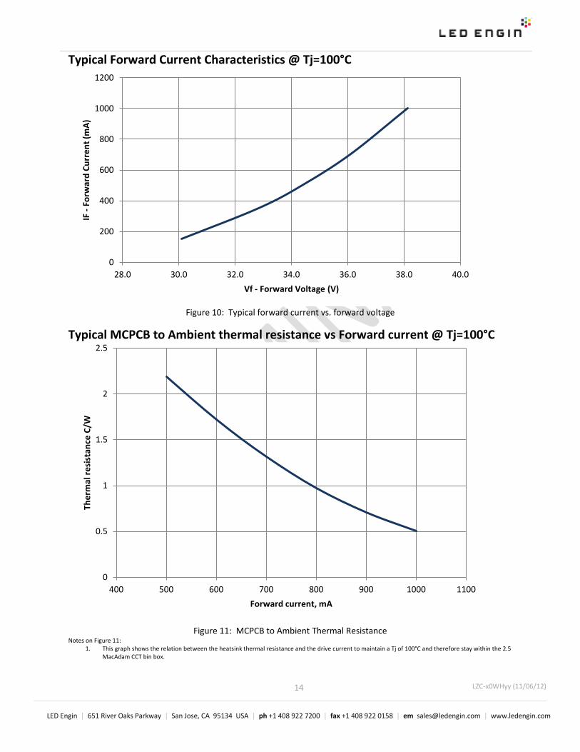
Typical Forward Current Characteristics @ Tj=100°C
Figure 10: Typical forward current vs. forward voltage
Typical MCPCB to Ambient thermal resistance vs Forward current @ Tj=100°C
Figure 11: MCPCB to Ambient Thermal Resistance
Notes on Figure 11: 1. This graph shows the relation between the heatsink thermal resistance and the drive current to maintain a Tj of 100°C and therefore stay within the 2.5
MacAdam CCT bin box.
0
200
400
600
800
1000
1200
28.0 30.0 32.0 34.0 36.0 38.0 40.0
IF -
Forw
ard
Curr
ent (
mA)
Vf - Forward Voltage (V)
0
0.5
1
1.5
2
2.5
400 500 600 700 800 900 1000 1100
Ther
mal
resi
stan
ce C
/W
Forward current, mA

15
LZC-x0WHyy (11/06/12)
LED Engin | 651 River Oaks Parkway | San Jose, CA 95134 USA | ph +1 408 922 7200 | fax +1 408 922 0158 | em [email protected] | www.ledengin.com
LZC MCPCB Family
Part number Type of MCPCB Diameter (mm)
MCPCB Thermal Resistance (oC/W)
Typical Vf (V)
Typical If (mA)
LZC-7xxxxx 1-channel serial 28.3 0.6 34.0 700
LZC-Cxxxxx 2-channel serial 28.3 0.6 17.0 2 x 700
LZC-Exxxxx 1-channel serial 49.6 0.6 34.0 700
LZC-Fxxxxx 1-channel; 2x6 parallel / serial 49.6 0.6 17.0 1400
Key Features
o Serial configuration allows for easy driver control with low current o 2 channel and 2x6 configurations allow for easy driver control with low Vf o Connector Boards have additional advantage of easy connections with poke-home connectors o Connector Boards have additional feedback through on-board thermistor to monitor MCPCB
temperatures
ESD protection
o MCPCB contains Zener Diodes for enhanced ESD protection
Mechanical Mounting of MCPCB o Mechanical stress on the emitter that could be caused by bending the MCPCB should be avoided. The
stress can cause the substrate to crack and as a result might lead to cracks in the dies. o Therefore special attention needs to be paid to the flatness of the heat sink surface and the torque
on the screws. Maximum torque should not exceed 1 Nm (8.9 lbf/in). o Care must be taken when securing the board to the heatsink to eliminate bending of the MCPCB. This
can be done by tightening the three M3 screws (or #4-40) in steps and not all at once. This is analogous to tightening a wheel of an automobile
o It is recommended to always use plastic washers in combination with three screws. Two screws could more easily lead to bending of the board.
o If non taped holes are used with self-tapping screws it is advised to back out the screws slightly after tighten (with controlled torque) and retighten the screws again.
Thermal interface material o To properly transfer the heat from the LED to the heatsink a thermally conductive material is required
when mounting the MCPCB to the heatsink o There are several materials which can be used as thermal interface material, such as thermal paste,
thermal pads, phase change materials and thermal epoxies. Each has pro’s and con’s depending on the application. For our emitter it is critical to verify that the thermal resistance is sufficient for the selected emitter and its environment.
o To properly transfer the heat from the MCPCB to the heatsink also special attention should be paid to the flatness of the heatsink.
Wire soldering for standard MCPCB For easy soldering of wires to the MCPCB it is advised to preheat the MCPCB on a hot plate to a maximum of 150°. Subsequently apply the solder and additional heat from the solder iron to initiate a good solder reflow. It is recommended to use a solder iron of more than 60W. We advise to use lead free, no-clean solder. For example SN-96.5 AG-3.0 CU 0.5 #58/275 from Kester (pn: 24-7068-7601)

16
LZC-x0WHyy (11/06/12)
LED Engin | 651 River Oaks Parkway | San Jose, CA 95134 USA | ph +1 408 922 7200 | fax +1 408 922 0158 | em [email protected] | www.ledengin.com
LZC-7xxxxx Emitter on 1-channel MCPCB
Notes: • All dimensions in mm. • Unless otherwise noted, the tolerance = ± 0.2 mm. • Slots in MCPCB are for M3 or #4-40 mounting screws. • LED Engin recommends plastic washers to electrically insulate screws from solder pads and electrical traces. • Electrical connection pads on MCPCB are labeled “+” for Anode and “-” for Cathode. • LED Engin recommends using thermal interface material when attaching the MCPCB to a heatsink. • The thermal resistance of the MCPCB is: RΘC-B 0.6°C/W
Components used MCPCB: HT04503 (Bergquist) ESD chips: BZX585-C51 (NPX, for 12 LED dies in series)
Pin Out
Pad Function
+ Anode Ch1
- Cathode Ch1

17
LZC-x0WHyy (11/06/12)
LED Engin | 651 River Oaks Parkway | San Jose, CA 95134 USA | ph +1 408 922 7200 | fax +1 408 922 0158 | em [email protected] | www.ledengin.com
LZC-Cxxxxx Emitter on 2-channel MCPCB Note: • All dimensions in mm. • Unless otherwise noted, the tolerance = ± 0.2 mm. • Slots in MCPCB are for M3 or #4-40 mounting screws. • LED Engin recommends plastic washers to electrically insulate screws from solder pads and electrical traces. • Electrical connection pads on MCPCB are labeled “+” for Anode and “-” for Cathode. • LED Engin recommends thermal interface material when attaching the MCPCB to a heatsink. • The thermal resistance of the MCPCB is: RΘC-B 0.6°C/W
Components used MCPCB: HT04503 (Bergquist) ESD chips: BZT52C36LP (NPX, for 6 LED dies in series)
Pin Out
Pad Function
1+ Anode Ch1
1- Cathode Ch1
2+ Anode Ch2
2- Cathode Ch2

18
LZC-x0WHyy (11/06/12)
LED Engin | 651 River Oaks Parkway | San Jose, CA 95134 USA | ph +1 408 922 7200 | fax +1 408 922 0158 | em [email protected] | www.ledengin.com
LZC-ExxxT1 Emitter on 1-channel MCPCB
Note: • All dimensions in mm. • Unless otherwise noted, the tolerance = ± 0.2 mm. angle = ± 1° • Slots in MCPCB are for M3 or #4-40 mounting screws. Maximum torque should not exceed 1N-m ( 8.9 lbf-in) • LED Engin recommends plastic washers to electrically insulate screws from solder pads and electrical traces. • LED Engin recommends using thermally interface material when attaching the MCPCB to a heatsink • For the connectors it is recommended to use solid wires with gauge size, 18, 20 or 22 AWG. It is recommended to strip the insulation of the wires to a length
of 4-5mm. When stranded wires are used it is recommended to twists the strands at the end of the wire and use wire extraction toll to insert the wires. • The thermal resistance of the MCPCB is: RΘC-B 0.6°C/W
Components used MCPCB: HT04503 (Bergquist) ESD chips: BZX585-C51 (NXP, for 12 LED dies in series) Thermistor: NCP15WF104F03RC (Murata, 100kOhm, please see www.murata.com for details
on calculating the thermistor temperature) Connectors: 00-9276-002-0-21-1-06 (AVX, poke-home)
Ch. Pad Emitter pin Function
1 LED1+ 14, 15 Anode LED1- 2, 3 Cathode
T NTC na Anode NTC na Cathode

19
LZC-x0WHyy (11/06/12)
LED Engin | 651 River Oaks Parkway | San Jose, CA 95134 USA | ph +1 408 922 7200 | fax +1 408 922 0158 | em [email protected] | www.ledengin.com
LZC-FxxxT1 Emitter on 1-channel MCPCB
Note: • All dimensions in mm. • Unless otherwise noted, the tolerance = ± 0.2 mm. angle = ± 1° • Slots in MCPCB are for M3 or #4-40 mounting screws. Maximum torque should not exceed 1N-m ( 8.9 lbf-in) • LED Engin recommends plastic washers to electrically insulate screws from solder pads and electrical traces. • LED Engin recommends using thermally interface material when attaching the MCPCB to a heatsink • For the connectors it is recommended to use solid wires with gauge size, 18, 20 or 22 AWG. It is recommended to strip the insulation of the wires to a length
of 4-5mm. When stranded wires are used it is recommended to twists the strands at the end of the wire and use wire extraction toll to insert the wires. • The thermal resistance of the MCPCB is: RΘC-B 0.6°C/W
Components used MCPCB: HT04503 (Bergquist) ESD chips: BZT52C36LP (NXP, for 6 LED dies in series) Thermistor: NCP15WF104F03RC (Murata, 100kOhm, please see www.murata.com for details
on calculating the thermistor temperature) Connectors: 00-9276-002-0-21-1-06 (AVX, poke-home)
Ch. Pad Emitter pin Function
1 LED1+ 14, 15, 17, 18 Anode LED1- 2, 3, 5, 6 Cathode
T NTC na Anode NTC na Cathode

20
LZC-x0WHyy (11/06/12)
LED Engin | 651 River Oaks Parkway | San Jose, CA 95134 USA | ph +1 408 922 7200 | fax +1 408 922 0158 | em [email protected] | www.ledengin.com
Wire Insertion and Extraction Instructions for connector boards For the connectors it is recommended to use solid wires with gauge size, 18, 20, 22 or 24 AWG. Push in and then give slight tug on the wire to confirm that it is properly engaged.
Extraction Tool References: Thin Blade Wire Extraction Tool: AVX P/N - 0692-7670-0101-000 Miniature Precision Screw Driver, 0.047” Tip Width
Wire Insertion
Solid conductor o Strip insulation length 4-5mm o Insert into appropriate hole to a stop o Inserted wire will be retained by contact
Stranded wire conductor o Twist strands together o Insert tool into contact operation slot o Insert wire o Remove tool
Wire extraction o Insert tool into contact o Extract wire o Remove tool

21
LZC-x0WHyy (11/06/12)
LED Engin | 651 River Oaks Parkway | San Jose, CA 95134 USA | ph +1 408 922 7200 | fax +1 408 922 0158 | em [email protected] | www.ledengin.com
Company Information LED Engin, Inc., based in California’s Silicon Valley, specializes in ultra-bright, ultra compact solid state lighting solutions allowing lighting designers & engineers the freedom to create uncompromised yet energy efficient lighting experiences. The LuxiGen™ Platform — an emitter and lens combination or integrated module solution, delivers superior flexibility in light output, ranging from 3W to 90W, a wide spectrum of available colors, including whites, multi-color and UV, and the ability to deliver upwards of 5,000 high quality lumens to a target. The small size combined with powerful output allows for a previously unobtainable freedom of design wherever high-flux density, directional light is required. LED Engin’s packaging technologies lead the industry with products that feature lowest thermal resistance, highest flux density and consummate reliability, enabling compact and efficient solid state lighting solutions. LedEngin is committed to providing products that conserve natural resources and reduce greenhouse emissions. LedEngin reserves the right to make changes to improve performance without notice. Please contact [email protected] or (408) 920-7200 for more information.