vital-bot 042208 thesis - university of florida
TRANSCRIPT
Vital-Bot Gabriel Reyes
04/22/08
University of Florida Electrical & Computer Engineering
Intelligent Machines Design Laboratory EEL5666C
Supervising Committee:
Dr. Jenshan Lin, Chair Dr. Eric Schwartz, Co-Chair
Dr. John Schueller Dr. Carl Crane
Teaching Assistants:
Mr. Changzhi Li Mr. Adam Barnett
Ms. Sara Keen Mr. Mike Pridgen

2
II. Table of Contents Section Page Number
I. Title Page 1 II. Table of Contents 2 III. Abstract 3 IV. Executive Summary 4 V. Introduction 5 VI. Integrated System 6 VII. Mobile Platform 7 VIII. Actuation
A. Servo Control 8 B. Motor Control 8
IX. Communications 9 X. Sensors
A. Overview 10 B. Bump sensor 10 C. Sonar range finder 10 D. Vital Signs (special sensor) 11-12
XI. Behaviors A. Autonomous 13 B. Remote Control 13
XII. Experimental Layout and Results 14 XIII. Conclusion 15 XIV. Acknowledgements 16 XV. Appendices
A. Microcontroller code 17-37 XVI. References 38 XVII. Pictures 39

3
III. Abstract Vital-Bot is a rugged mobile robot for indoor and outdoor terrain. It is integrated with a vital signs sensing system capable of detecting a human’s heartbeat and it is designed for search-and-rescue missions. Vital-Bot is programmed to explore a certain area and use radar from the vital signs system to detect human presence. Vital-Bot is able to avoid obstacles and communicates with an operational base station (laptop computer) using Xbee wireless communication modules. The base station receives data from the vital signs system and uses LabVIEW to process the data and determine whether or not a human has been detected. LabVIEW then transmits a ‘human detected’ flag instructing Vital-Bot to remain stationary or continue searching the area. Vital-Bot is also equipped with a wireless web camera allowing a remote user to drive the robot from the base station using a Nintendo Wii controller.

4
IV. Executive Summary Vital-Bot is a mobile robot developed at the Radio Frequency System-On-Chip Laboratory and the Machine Intelligence Laboratory, as part of the Intelligent Machines Design Laboratory. It was designed and built with the intent of exploring indoor and outdoor environments for search-and-rescue missions. The main sensor on Vital-Bot is a highly complex integrated circuit sensor used to detect a person’s vital signs with two radar antennas operating at 5.8 GHz. The miniaturized radar sensor was initially designed to allow a medical patient to transmit their vital signs to medical personnel over existing networks, such as the internet or a cell phone connection. Vital-Bot takes this sensor application to the next level. Vital-Bot will autonomously navigate around a certain area until it encounters an obstacle directly in front of it. At this time, the vital signs sensor takes over. It will scan the area directly in front of the robot and transmit the data collected to a base station. The base station then communicates with the robot to update the status of the human search-and-rescue by indicating whether or not a ‘live human’ is found. The applications of the vital signs sensor range from the developing field of telemedicine, to sleep apnea monitoring, translation of throat vibrations into speech, and law enforcement monitoring during questioning procedures. In this project, Vital-Bot will search for ‘live humans’ by detecting a person’s heartbeat and respiration. Vital-Bot has been a wonderful learning experience as a project combining the areas of radar sensors, wireless communications, and robotics. The project is highly multi-disciplinary and it will be further developed into a research platform for more advanced search-and-rescue operations.
5
V. Introduction Imagine a portable system that can monitor a person’s breathing and heart rate automatically via a wireless signal, with no need for cords or plugs, and then transmits the signal over a cell phone or internet connection. The goal is to make it easy for people to check their own vital signs, and then transmit them to medical personnel from the comfort of their homes as easily as possible. The system consists of a miniaturized Doppler radar housed inside of an iPod-sized circuit board connected to external antennas. High-frequency waves broadcast by the radar bounce off a person, scanning the in-and-out movement of the chest and the more subtle, but also detectable, motion of the heartbeat against the chest wall. Currently, there are remaining challenges and further research work required which includes upgrading the hardware and software to enhance the system’s resolution so multiple heartbeats can be detected and distinguished simultaneously, as well as improving its range and sensitivity. This technology has many other applications in the real world. For example, engineers might be able to tune it to “observe” the vibrations of a speech-impaired person’s throat and then translate those vibrations into computer-produced speech. Outside the field of medicine, it is possible for law enforcement officials to use the system as a surreptitious indicator of a subject’s nervousness, noting when his or her heart rate or pulse picks up in response to certain questions. The proposed project, for the scope of this research paper, involves a multidisciplinary research platform combining the field of robotics, wireless communications, radar, and sensors. Vital-Bot is a mobile surveillance robot that communicates using wireless technology and navigates any given indoor or outdoor terrain. Furthermore, the robot will carry the vital signs sensing system mounted as part of its design. Given the current size of the vital signs sensing system, the integration of the technology onto any medium-sized robot is not an issue.

6
VI. Integrated System The integrated system of this project consists of two units. The first unit is the medium-sized robot itself, called Vital-Bot, and the second is a base station composed of a laptop computer with wireless connectivity. These two units communicate with each other using dual Xbee communication boards. The Vital-Bot system is operated using a Mavric-IIB board from BDMicro with an Atmel ATMega128 microprocessor and is connected to an array of sensors including: sonar, bump, and the vital signs system. Vital-Bot also has LCD and LED feedback and is connected to a servo to move a wireless camera in any horizontal direction. The Mavric-IIB board has two available serial ports for communication with other devices or sensors. One of the serial ports is used to receive motor commands from the base station through dual Xbee boards. Vital-Bot has its own dual motor driver board, the ScorpionXL from RobotMarketPlace, and connects to four Lynxmotion gear head motors for navigation in any terrain. A 2.4GHz wireless camera is also mounted on the robot. The vital signs sensing system is mounted on the front of the robot and the data collected by the radio frequency circuit is converted from analog to digital using an MSP430 microcontroller. The digital data is then sent to the base station computer using a second Xbee communications board. The Base Station consists of a laptop computer running Windows XP Pro. The computer is connected to an Xbee transceiver using a USB port and this creates an invisible wireless communication tunnel between the computer and Vital-Bot. An audio/video receiver for the webcam connects to an external LCD display using an RCA cable, allowing a remote user to “see” what is in front of the robot. A LabVIEW control software interface has been developed to receive the data from the vital signs sensing system, display the heartbeat, and determine whether or not a human has been detected by Vital-Bot. LabVIEW will send commands back to the robot based on the information from the vital signs system. In addition to LabVIEW, a C# program has been developed in Visual Studio Express 2005 to connect to a Nintendo Wii controller using a Bluetooth adapter and it will allow a remote user to control the robot from the base station.

7
VII. Mobile Platform The mobile platform has been constructed of 0.220” thick transparent Plexiglas. A two tier platform was designed using a 17” x 11” piece for the bottom level and a 10” x 8” piece for the top level. The motors are mounted directly onto the bottom level of Plexiglas using aluminum brackets and the following components are mounted on the lower level of the platform: 3 sonars, vital signs sensor, MSP430 microprocessor and Xbee transmitter, 2 x 6V batteries, motor driver, bump sensor board, and 3 bump sensors. The top level of the platform includes: Mavric-IIB board, wireless camera and pan servo, an LCD display, a buzzer, and an Xbee communication board. There are also 4 switches mounted throughout the robot controlling power to the motors and driver board, to the Mavric-IIB board and vital signs sensor, the wireless camera, and a fourth button to reset the Mavric-IIB board and initialize the robot.
8
VIII. Actuation
A. Servo Control The selected servo for this project is the Deluxe Hitec HS-475HB Servo. With 76 oz-in. of power, ball bearings, one piece circuit board and Karbonite gears, this servo is commonly used for all types of robotic applications due to its well known performance and durability. The servo will be used to rotate the camera in any horizontal direction facing forward on the robot. The servo may be operated at 4.8 to 6.0 is pictured here.
B. Motor Control
The motor that Vital-Bot will be using are the GHM-14 from Lynxmotion. These motors are rated for a 12V dc voltage and are capable of operating at 200 rpm and a stall torque of 255.25 oz-in. The gear reduction ratio is 30:1 and the motors weigh about 6.72oz. The outside diameter is 37mm and a 6mm shaft is required to connect to the outdoor wheels.

9
IX. Communications The Xbee Pro 802.15.4 RF modules were used for the wireless communications in this project. These modules were chosen due to their low-cost and low-power consumption for use in the wireless sensor network applications. The Xbee units were very easy to use and offered very reliable communication between the devices. The Xbee modules were used as follows. The Xbee base module is located at the laptop base station and is accessed through a serial port in the LabVIEW program. The Xbee base module is able to send and receive data as required. The vital signs sensor on-board the robot collects information via its radar antennas and processes the information on its own integrated circuit board. The vital signs sensor then transmits the processed data to a microcontroller that handles the analog to digital conversion and then sends the data to an Xbee transmitter module. This module sends the digital data wirelessly to the Xbee base module connected to LabVIEW. Once LabVIEW has processed the data inputted from the vital signs sensor it will output a ‘live human detected’ flag indicating whether or not a human is present, according to the radar signals available. LabVIEW will constantly transmit this ‘live human detected’ flag to Vital-Bot using the Xbee base module. A third Xbee module in receive mode has been placed on the robot and is connected to the Mavric-IIB robot microcontroller. The ‘live human detected’ flag is used to instruct Vital-Bot to remain stationary or continue roaming around until a human is found. This three-way communication between the vital signs sensor, the robot, and the base station is accomplished using the following addresses programmed into the Xbee modules:
Xbee Module Destination Address Source Address 1. Base Station 07 (to robot) 01 (from vital signs) 2. Vital Signs 01 (to base station) 09 (any value besides 07 or 11) 3. Robot 11 (any value besides 01 or 09) 07 (from base station)
10
X. Main Sensors
A. Overview
The world we live in is a complex place. We have many senses to help us to understand our surroundings, but in order for robots to roam around safely sensors are also required to understand their environment. The easiest way of doing this is to add simple sensors to you robot. A number of sensors are connected to the Vital-Bot microcontroller, ranging from an array of sonar finders, bump sensors for collisions, and a special sensor featured: a vital signs sensor. Each sensor is described in detail below.
B. Bump Sensors
Vital-Bot is happily driving around but in the case it keeps colliding with obstacles and getting stuck, it will need a way to detect collisions and move around objects. Enter the bump sensor. A bump sensor is probably one of the easiest ways of letting your robot know it's collided with something.
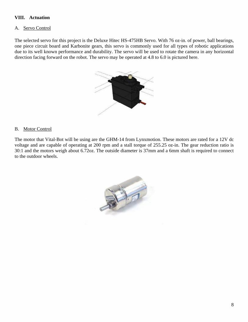
The simplest way to do this is to fix a micro switch to the front of your robot in a way so that when it collides the switch will get pushed in, making an electrical connection. Normally the switch will be held open by an internal spring. Micro switches are easy to connect to microcontrollers because they are either off or on, making them digital. Bump sensors are easily connected to the ATMega128, simply plug them into any available input/output pin.
The following diagram shows a typical circuit for a bump sensor. The resistor is important because it holds the signal line at ground while the switch is off. Without it the signal line is effectively 'floating' because there is nothing connected to it, and may cause unreliable readings as the processor tries to decide if the line is on or off.
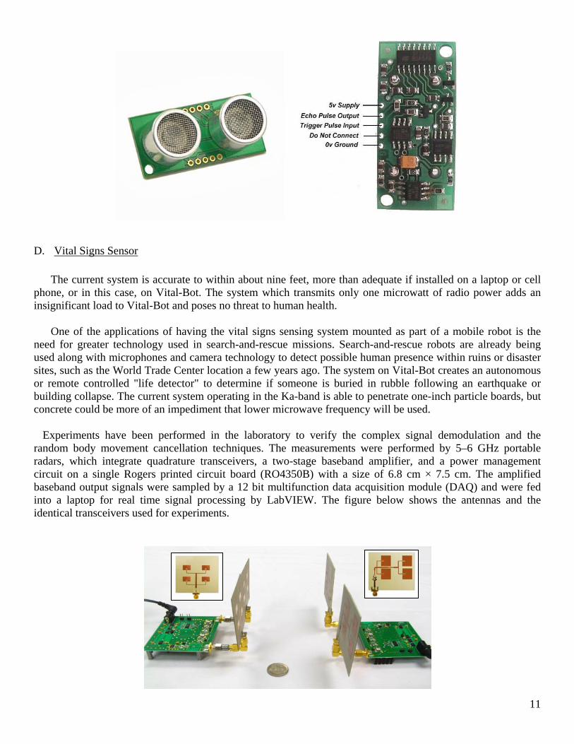
C. Sonar Range Finders An array of Devantech SRF05 sonar range finders will be used to monitor the lateral proximity of the robot with any obstacles. The SRF05 is the low-cost successor to the extremely popular SRF04 detector. Improvements in the design and manufacturing have allowed the price to come down. Also, better features are included such as an LED status indicator that blinks when the sonar fires as well as a new single-wire mode of operation. The range has also increased to 4 meters. The SRF05 is featured here.
11
D. Vital Signs Sensor The current system is accurate to within about nine feet, more than adequate if installed on a laptop or cell phone, or in this case, on Vital-Bot. The system which transmits only one microwatt of radio power adds an insignificant load to Vital-Bot and poses no threat to human health. One of the applications of having the vital signs sensing system mounted as part of a mobile robot is the need for greater technology used in search-and-rescue missions. Search-and-rescue robots are already being used along with microphones and camera technology to detect possible human presence within ruins or disaster sites, such as the World Trade Center location a few years ago. The system on Vital-Bot creates an autonomous or remote controlled "life detector" to determine if someone is buried in rubble following an earthquake or building collapse. The current system operating in the Ka-band is able to penetrate one-inch particle boards, but concrete could be more of an impediment that lower microwave frequency will be used.
Experiments have been performed in the laboratory to verify the complex signal demodulation and the random body movement cancellation techniques. The measurements were performed by 5–6 GHz portable radars, which integrate quadrature transceivers, a two-stage baseband amplifier, and a power management circuit on a single Rogers printed circuit board (RO4350B) with a size of 6.8 cm × 7.5 cm. The amplified baseband output signals were sampled by a 12 bit multifunction data acquisition module (DAQ) and were fed into a laptop for real time signal processing by LabVIEW. The figure below shows the antennas and the identical transceivers used for experiments.
12
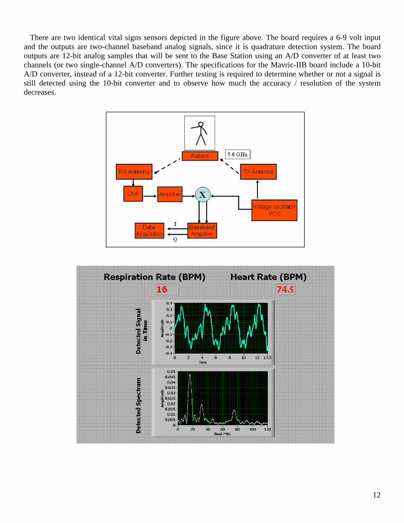
There are two identical vital signs sensors depicted in the figure above. The board requires a 6-9 volt input
and the outputs are two-channel baseband analog signals, since it is quadrature detection system. The board outputs are 12-bit analog samples that will be sent to the Base Station using an A/D converter of at least two channels (or two single-channel A/D converters). The specifications for the Mavric-IIB board include a 10-bit A/D converter, instead of a 12-bit converter. Further testing is required to determine whether or not a signal is still detected using the 10-bit converter and to observe how much the accuracy / resolution of the system decreases.
13
XI. Behaviors
A. Autonomous The objective of the Intelligent Machines Design Laboratory course is to design, build, and demo a working autonomous robot capable of carrying out a specific task. Vital-Bot is a search-and-rescue robot that uses radar to detect a person’s heartbeat and it will be used for search-and-rescue missions. The robot will be free to roam around any area using its sensors to avoid obstacles. Once it encounters an obstacle, it will stop and it will enable the vital signs sensing system. The vital signs data collected from the sensor is inputted into an A/D converter on the Mavric-IIB board and sent to the Base Station computer running a LabVIEW control program. The LabVIEW control software displays the data in the form of a graph on screen and determines whether or not a human has been detected by the radar due to variations in the 12-bit data stream collected. LabVIEW will then send a ‘human detected’ byte to the robot using one of the system’s Xbee boards and Vital-Bot will flash its lights or turn on a siren. If LabVIEW determines a human has not been detected, it will send a ‘human not detected’ byte to the robot and Vital-Bot will continue roaming the area using its sensors until it finds a human.
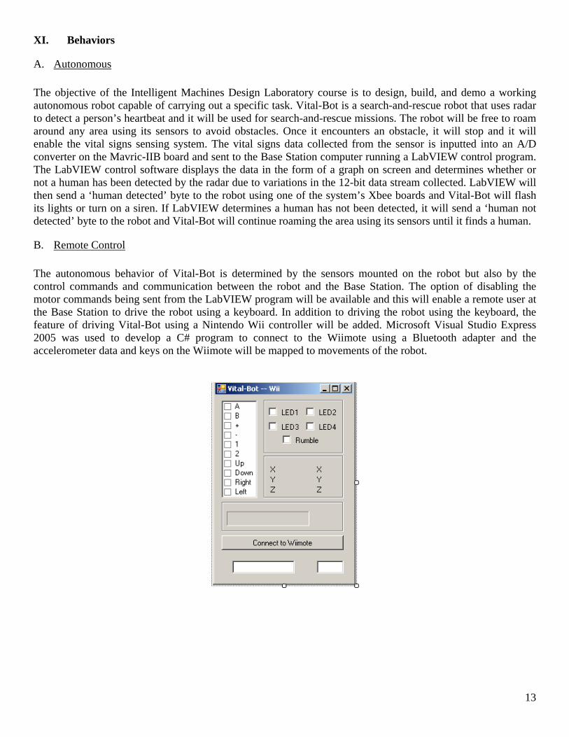
B. Remote Control The autonomous behavior of Vital-Bot is determined by the sensors mounted on the robot but also by the control commands and communication between the robot and the Base Station. The option of disabling the motor commands being sent from the LabVIEW program will be available and this will enable a remote user at the Base Station to drive the robot using a keyboard. In addition to driving the robot using the keyboard, the feature of driving Vital-Bot using a Nintendo Wii controller will be added. Microsoft Visual Studio Express 2005 was used to develop a C# program to connect to the Wiimote using a Bluetooth adapter and the accelerometer data and keys on the Wiimote will be mapped to movements of the robot.
14
XII. Experimental Layout Vital-Bot was tested in an indoor laboratory environment in order to reduce any random noise created by external factors such as background movement, random body movement, and other changes in the environment. A short course was created for Vital-Bot to demonstrate its wall following and obstacle avoidance capabilities. Two tests of the vital signs sensor were created by placing a path for Vital-Bot to follow. After the first stage of the course, an object representing a possible human obstacle was laid out in front of the robot. Vital-Bot uses its sonar modules to come to a full stop and then uses the vital signs sensor to decide that there is no ‘live human’ detected in its way. Vital-Bot will then reverse and turn into the second stage of the course following a wall leading to a human sitting at the end. Once the human is directly in front of Vital-Bot it will stop and wait for instructions from the vital signs sensor status flag. Once it determines that a human is found, Vital-Bot will sound off an alarm and remain stationary until the human disappears. Some of the issues encountered in the experimental process of this project include further sensitivity in the obstacle avoidance algorithms to establish greater distance between Vital-Bot and other objects. Vital-Bot is limited to the viewable range of the sonar scope in detecting obstacles. For further improvements, sonar modules could be installed on the sides and the rear of Vital-Bot to further avoid any collisions along the way. A calibration of the DC offset and an experimental threshold are required in order for the remote user and LabVIEW to properly detect a human based on the data from the vital signs sensor. It is important the careful attention is made when calibrating the sensor in order to observe reliable results when Vital-Bot is activated. One of the other issues faced in working with the vital signs sensor is that there is currently no documentation made available indicating any of the performance parameters or device details as the sensor is still currently in the testing and reliability phases. Finally, one of the last issues faced in using the vital signs sensor for testing is that the antennas must be pointed directly at the human in order to capture accurate and reliable data using radar. In this case, it was decided that the human patient would be sitting at the ground level in order for Vital-Bot to detect their vital signs. This was not considered a major issue as in the case of search-and-rescue, the human survivor will most likely be found in a motionless state, either laying down or sitting, at the ground level. This will make it easier for Vital-Bot to detect any human presence and avoid noise from larger objects in the area.

15
XIII. Conclusion Vital-Bot is an interesting multidisciplinary project that involves the fields of robotics, radar sensors, wireless communications, and a variety of other sensors. Existing technology for search-and-rescue has mainly involved the use of audio and visual capabilities, but Vital-Bot presents a much more innovative approach using radar to penetrate through rubble and other non-metallic materials in an attempt to find human survivors in a disaster area. The integration of Vital-Bot and the vital signs sensor proved to be successful thanks to an integrated system created using multiple microprocessors for data processing and multiple Xbee wireless communication modules to exchange information between systems. The wireless communications also provided a remote user the ability to monitor Vital-Bot at any stage of its search-and-rescue. For future development of this project, a MiniITX motherboard will be added to allow for signal processing to occur on-board the robot. Wi-Fi communications at the robot and base station will also allow for more complete control of Vital-Bot from a remote location. Feedback from the vital signs and battery status will be sent wireless to the remote user at all times. Another feature that could be added is on-board image processing allowing Vital-Bot to not only detect human presence using its radar sensors but also using more complex camera capabilities. A redesign of the platform is not required, but the possibility of manufacturing the platform out of metal to make it more durable has been considered. In addition to the current motor components and motor driver, a digital isolator board will be added to protect against any current spikes caused by the motors, which could potentially damage the robot microcontroller and the other sensors in the integrated system.

16
XIV. Acknowledgements Special thanks are given to Dr. Jenshan Lin for his support throughout this project, and to Mr. Changzhi Li for his wonderful work on the vital signs sensor and its integration with the Vital-Bot system. Dr. Lin and Mr. Li are both members of the Radio Frequency System-On-Chip Laboratory (RFSOC) at the University of Florida. Also, thanks to Dr. Eric Schwartz and Dr. Arroyo from the Machine Intelligence Laboratory for their guidance and supervision as part of the Intelligent Machines Design Laboratory course at the University of Florida. Thanks are given to Dr. John Schueller and Dr. Carl Crane for their valuable feedback and participation as part of the supervisory committee for this honors thesis project. Thanks are given to the Intelligent Machines Design Laboratory teaching assistants: Adam Barnett, Mike Pridgen and Sara Keen, for their recommendations and help throughout the semester. Also, thanks to Jason Taylor for his assistance with ProEngineer and platform design. Finally, thanks for the financial support of this project are given to the University Scholars Program, Golden Key Honor Society Research Grant, IEEE Microwave Theory and Techniques Society Undergraduate Fellowship, and Dr. Jenshan Lin at the RFSOC.

17
XV. Appendices --------------------------------------------------------------------------------------------------------------------------------------- -------------------------------------------------Bump Sensor Code (bump.c)--------------------------------------------------- #include "bump.h" #include "camera.h" #include "chime.h" #include "init.h" #include "lcd.h" #include "main.h" #include "motors.h" #include "uart0.h" #include "vital.h" unsigned int bumpx; void bump_config() { portF_init(); // set PORTF=0xFE (pin1=input) // Note: when JTAGEN fuse is set, F4 - F7 don't work // make sure pull up resistor is not enabled ADMUX = 0b01000000; // 5V reference, select channel0 (pin F0) ADCSRA |= 0b10000111; // turn on ADC, don't start conversions // channel enable only, disable interrupt // divide clock by 128 } int bump_get() { ADMUX = 0b01000000; // Start AD conversion ADCSRA |= (1 << ADSC); // Wait for ADC conversion to complete while (ADCSRA & (1 << ADSC)); //place ACD value into one variable bumpx = ADCL | (ADCH << 8); return bumpx; } void bump_behave() { // bumpval = bump_get(); }
18
-------------------------------------------------Bump Sensor Code (bump.h)-------------------------------------------------- #include <avr/io.h> #include <avr/interrupt.h> #include <avr/pgmspace.h> #include <stdio.h> #include <ctype.h> #include <stdlib.h> #include <string.h> #include <inttypes.h> #include <math.h> extern void bump_config(void); extern int bump_get(void); extern void bump_behave(void);

19
--------------------------------------------------------------------------------------------------------------------------------------- -------------------------------------------------Camera/Servo Code (camera.c)------------------------------------------------ #include "bump.h" #include "camera.h" #include "chime.h" #include "init.h" #include "lcd.h" #include "main.h" #include "motors.h" #include "uart0.h" #include "vital.h" void camera_init() { // Timer/Counter 1 initialization // Clock source: System Clock // Clock value: 1843.200 kHz // Mode: Ph. & fr. cor. PWM top=ICR1 // OC1A output: Non-Inv. // OC1B output: Off. // OC1C output: Off. // Noise Canceler: Off // Input Capture on Falling Edge // Timer 1 Overflow Interrupt: Off // Input Capture Interrupt: Off // Compare A Match Interrupt: Off // Compare B Match Interrupt: Off // Compare C Match Interrupt: Off TCCR1A=0x80; TCCR1B=0x12; TCNT1H=0x00; TCNT1L=0x00; ICR1=18432; OCR1A=1382; camera=1382; us50_sleep(800); } void camera_front() { camera=1382; us50_sleep(400); } void camera_left() {

20
camera=922; us50_sleep(400); } void camera_right() { camera=1843; us50_sleep(400); } void camera_scan() { camera_front(); camera_left(); camera_front(); camera_right(); camera_front(); } -------------------------------------------------Camera/Servo Code (camera.h)------------------------------------------------ #include <avr/io.h> #include <avr/interrupt.h> #include <avr/pgmspace.h> #include <stdio.h> #include <ctype.h> #include <stdlib.h> #include <string.h> #include <inttypes.h> #include <math.h> extern void camera_init(void); extern void camera_front(void); extern void camera_left(void); extern void camera_right(void); extern void camera_scan(void); #define camera OCR1A

21
--------------------------------------------------------------------------------------------------------------------------------------- -------------------------------------------------Buzzer/Chime Code (chime.c)------------------------------------------------- #include "bump.h" #include "camera.h" #include "chime.h" #include "init.h" #include "lcd.h" #include "main.h" #include "motors.h" #include "sonar.h" #include "uart0.h" #include "vital.h" void chime_init() { chime = (1<<PINA0); us50_sleep(300); chime = (0<<PINA0); us50_sleep(400); chime = (1<<PINA0); us50_sleep(500); chime = (0<<PINA0); } void chime_on() { chime = (1<<PINA0); } void chime_off() { chime = (0<<PINA0); } -------------------------------------------------Buzzer/Chime Code (chime.h)----------------------------------------------- #include <avr/io.h> #include <avr/interrupt.h> #include <avr/pgmspace.h> #include <stdio.h> #include <ctype.h> #include <stdlib.h> #include <string.h> #include <inttypes.h> #include <math.h> extern void chime_init(void); extern void chime_on(void); extern void chime_off(void); #define chime PORTB

22
--------------------------------------------------------------------------------------------------------------------------------------- -------------------------------------------------Initialization Code (init.c)------------------------------------------------------ #include "bump.h" #include "camera.h" #include "chime.h" #include "init.h" #include "lcd.h" #include "main.h" #include "motors.h" #include "sonar.h" #include "uart0.h" #include "vital.h" int us50_sleep(int x) { uint16_t i,j; uint16_t delay=0; for(i=0;i<x;i++) for(j=0;j<1000;j++) delay++; return delay; } void portA_init() //PortA - LCD { DDRA=0b11111111; PORTA=0x00; } void portB_init() //PortB - Pin1=Chime, Pin5=Servo/Motor { DDRB=0b00100001; PORTB=0x00; } void portC_init() //PortC - Sonar (0in/out/in/out/in/out/out/out7) { DDRC=0b11101010; PORTC=0x00; } void portD_init() //PortD - Unused { DDRD=0b11111111; PORTD=0x00; } void portE_init() //PortE - Pin1=Xbee RxTx { DDRE=0b11111110; PORTE=0x00;
23
} void portF_init() //PortF - Pin1=Bump A/D { DDRF=0b11111110; PORTF=0x00; } void portG_init() //PortG - Unused { DDRG=0b11111111; PORTB=0x00; } void init_ports() { portA_init(); portB_init(); portC_init(); portD_init(); portE_init(); portF_init(); portG_init(); } void init() { init_ports(); us50_sleep(100); bump_config(); lcd_init(); camera_init(); uart0_init(); lcd_string(" Vital-Bot Live "); us50_sleep(200); lcd_clear(); //chime_init(); motor_init(); lcd_string("Camera Scan"); us50_sleep(300); lcd_clear(); //camera_scan(); //lcd_string("Sonars On"); //us50_sleep(500); lcd_clear(); lcd_string("Ready in..."); us50_sleep(500); lcd_clear(); lcd_string("3");
24
us50_sleep(300); lcd_clear(); lcd_string("2"); us50_sleep(300); lcd_clear(); lcd_string("1"); us50_sleep(300); lcd_clear(); lcd_string("Go!"); us50_sleep(300); } -------------------------------------------------Initialization Code (init.h)---------------------------------------------------- #include <avr/io.h> #include <avr/interrupt.h> #include <avr/pgmspace.h> #include <stdio.h> #include <ctype.h> #include <stdlib.h> #include <string.h> #include <inttypes.h> #include <math.h> extern int us50_sleep(int x); extern void portA_init(void); extern void portB_init(void); extern void portC_init(void); extern void portD_init(void); extern void portE_init(void); extern void portF_init(void); extern void portG_init(void); extern void init_ports(void); extern void init(void);
25
--------------------------------------------------------------------------------------------------------------------------------------- -------------------------------------------------LCD Display Code (lcd.c)------------------------------------------------------ #include "bump.h" #include "camera.h" #include "chime.h" #include "init.h" #include "lcd.h" #include "main.h" #include "motors.h" #include "uart0.h" #include "vital.h" int pos=0; void lcd_command(int db) { lcd=(db >> 4) | E0; us50_sleep(1); lcd=db >> 4; us50_sleep(5); lcd=(db & 0x0F) | E0; us50_sleep(1); lcd=db & 0x0F; us50_sleep(100); } void lcd_clear() { //Clear Home lcd_command(0x01); pos=0; } void lcd_data(char db) { // proper line wrap: //if (pos==16) // lcd_command(0xC0); //if (pos==32) // lcd_command(0x94); lcd=(db >> 4) | E0 | RS; us50_sleep(1); lcd=(db >> 4) | RS; us50_sleep(1); lcd=(db & 0x0F) | E0 | RS; us50_sleep(1); lcd=(db & 0x0F) | RS; //us50_sleep(1);
26
//if (++pos==80) //pos = 0; } void lcd_init() { us50_sleep(300); //15 //initialize to 4 bit mode: lcd_command(0x33); us50_sleep(100); lcd_command(0x32); //2 lines 5x8 font lcd_command(0x28); //Display, no Curser, no Blink lcd_command(0x0C); // F cursor and blink, E just cursor lcd_clear(); } void lcd_string(char db []) { for (; *db!='\0';db++) lcd_data(*db); } void lcd_int(int value) { /* This routine will take an integer and display it in the proper order on your LCD. Thanks to Josh Hartman (IMDL Spring 2007) for writing this in lab */ int temp_val; int x = 10000; // since integers only go up to 32768, we only need to worry about // numbers containing at most a ten-thousands place while (value / x == 0) // the purpose of this loop is to find out the largest position (in decimal) { // that our integer contains. As soon as we get a non-zero value, we know x/=10; // how many positions are in the int and x will be initialized to largest } // power of 10 that will return a non-0 value when our integer is divided by x if (value==0) lcd_data(0x30); else while (x >= 1) // this loop is where the printing to the LCD takes place. First, we divide { // our integer by x (properly initialized by the last loop) and store it in temp_val = value / x; // a temporary variable so our original value is preserved.Next subs the value -= temp_val * x; // the temp variable times x from original value. Will "pull" off the most lcd_data(temp_val+ 0x30); // signif digit from original int but leave all the remaining digits alone // After, add a hex 30 to temp variable because ASCII values for integers
27
x /= 10; // 0 to 9 correspond to hex 30 through 39. We then send this value to the } // LCD (understands ASCII). Finally, we divide x by 10 and repeat // until a zero value (note: since our value is an integer, any decimal value return; // less than 1 will be truncated to a 0) } void lcd_row(int row) { switch(row) { case 0: lcd_command(0x02); case 1: lcd_command(0xC0); } return; } -------------------------------------------------LCD Display Code (lcd.h)---------------------------------------------------- #include <avr/io.h> #include <avr/interrupt.h> #include <avr/pgmspace.h> #include <stdio.h> #include <ctype.h> #include <stdlib.h> #include <string.h> #include <inttypes.h> #include <math.h> extern void lcd_command(int db); extern void lcd_clear(void); extern void lcd_data(char db); extern void lcd_init(void); extern void lcd_string(char db []); extern void lcd_int(int value); extern void lcd_row(int row); #define E0 0x40 #define RS 0x10 #define lcd PORTA char buffer[10];
28
--------------------------------------------------------------------------------------------------------------------------------------- -------------------------------------------------Main Code (main.c)------------------------------------------------------------- #include "bump.h" #include "camera.h" #include "chime.h" #include "init.h" #include "lcd.h" #include "main.h" #include "motors.h" #include "sonar.h" #include "uart0.h" #include "vital.h" int human; unsigned int bumpval; long sl=0; long sc=0; long sr=0; void human_detect(long sc) { if(sc < 2200) { motors(0,0); us50_sleep(10000); if(human == 48) { lcd_clear(); lcd_string("No Human"); us50_sleep(250); chime_off(); motors(-400,-400); us50_sleep(800); motors(400,-400); us50_sleep(500); } while(human != 48) { lcd_clear(); lcd_string("Human"); us50_sleep(250); chime_on(); } motors(-400,-400); us50_sleep(400); }

29
} int main(void) { init(); sei(); while(1) { bot_forward(); chime_off(); sc = sonar_center(); sl = sonar_left(); sr = sonar_right(); lcd_clear(); lcd_int(sc); human_detect(sc); avoid(sl,sr); } } ISR(USART0_RX_vect) { human=UDR0; } -------------------------------------------------Main Code (main.h)------------------------------------------------------------ #include <avr/io.h> #include <avr/interrupt.h> #include <avr/pgmspace.h> #include <stdio.h> #include <ctype.h> #include <stdlib.h> #include <string.h> #include <inttypes.h> #include <math.h> void human_detect(long sc); ISR(USART0_RX_vect);

30
--------------------------------------------------------------------------------------------------------------------------------------- -------------------------------------------------Motors Code (motors.c)--------------------------------------------------------- #include "bump.h" #include "camera.h" #include "chime.h" #include "init.h" #include "lcd.h" #include "main.h" #include "motors.h" #include "sonar.h" #include "uart0.h" #include "vital.h" void motors(int16_t s5, int16_t s6) { motor_l = offset(s5); motor_r = offset(s6); } void motor_init() { // Timer/Counter 3 initialization // Clock source: System Clock // Clock value: 1843.200 kHz // Mode: Ph. & fr. cor. PWM top=ICR3 // Noise Canceler: Off // Input Capture on Falling Edge // OC3A output: Non-Inv. // OC3B output: Non-Inv. // OC3C output: Discon. // Timer 3 Overflow Interrupt: Off // Input Capture Interrupt: Off // Compare A Match Interrupt: Off // Compare B Match Interrupt: Off // Compare C Match Interrupt: Off TCCR3A=0xA0; TCCR3B=0x12; TCNT3H=0x00; TCNT3L=0x00; ICR3=18432; motor_l=1382; motor_r=1382; us50_sleep(800); } void bot_stop() {

31
motors(0,0); us50_sleep(400); } void bot_forward() { motors(400,385); } void bot_reverse() { int i; motors(-450,-440); for(i=0;i<10;i++); { us50_sleep(100); } } void bot_right() { int i; motors(-400,400); for(i=0;i<5;i++) { us50_sleep(100); } } void bot_left() { int i; motors(400,-400); for(i=0;i<5;i++) { us50_sleep(100); } } void bot_spin() { int i; motors(400,-400);

32
for(i=0;i<10;i++) { us50_sleep(100); } } void avoid(long sl, long sr) { if(sl >= 1300 && sl <= 2000) { lcd_clear(); lcd_string("Sonar Left"); motors(400,300); us50_sleep(600); } else if(sl < 1300) { lcd_clear(); lcd_string("Left Stop"); motors(0,0); us50_sleep(200); motors(-400,-400); us50_sleep(700); motors(400,300); us50_sleep(300); } else if(sr >= 1300 && sr <= 2000) { lcd_clear(); lcd_string("Sonar Right"); motors(300,400); us50_sleep(600); } else if(sr < 1300) { lcd_clear(); lcd_string("Right Stop"); motors(0,0); us50_sleep(200); motors(-400,-400); us50_sleep(700); motors(300,400); us50_sleep(300); } }

33
-------------------------------------------------Motors Code (motors.h)------------------------------------------------------- #include <avr/io.h> #include <avr/interrupt.h> #include <avr/pgmspace.h> #include <stdio.h> #include <ctype.h> #include <stdlib.h> #include <string.h> #include <inttypes.h> #include <math.h> #define motor_l OCR3A #define motor_r OCR3B #define servo_min 922 #define servo_mid 1382 #define servo_max 1843 #define l_close 1200 #define l_far 1500 #define c_close 500 #define c_far 1200 #define r_close 1200 #define r_far 1500 #define servo_clip(x) (x<servo_min ? servo_min : (x>servo_max ? servo_max : x)) #define offset(y) (servo_clip(servo_mid + y)) extern void motors(int16_t s5, int16_t s6); extern void motor_init(void); extern void bot_stop(void); extern void bot_forward(void); extern void bot_reverse(void); extern void bot_right(void); extern void bot_left(); extern void bot_spin(); extern void avoid(long sl, long sr);

34
--------------------------------------------------------------------------------------------------------------------------------------- -------------------------------------------------Sonar Code (sonar.c)------------------------------------------------------------ #include "bump.h" #include "camera.h" #include "chime.h" #include "init.h" #include "lcd.h" #include "main.h" #include "motors.h" #include "sonar.h" #include "uart0.h" #include "vital.h" unsigned int prev_left[2]; unsigned int prev_right[2]; int sonar_right() { int n = 0; PORTC = (PINC & 0b11111101); // these two lines create a rising edge PORTC = (PINC | 0b00000010); // on PortC pin 1 while (n < 80) { n += 1; //waste clock cycles for at least 10us n++; } PORTC = (PINC & 0b11111101); // force PortC pin 1 low to create a falling edge // this sends out the trigger while (!(PINC & 0b00000001)) { // do nothing as long as echo line is low } n = 0; //re-use our dummy variable for counting while (PINC & 0b00000001) { n += 1; // add 1 to n as long as PortC pin 0 is high } //when we get here, the falling edge has occured return n; } int sonar_center()
35
{ int n = 0; PORTC = (PINC & 0b11110111); // these two lines create a rising edge PORTC = (PINC | 0b00001000); // on PortC pin 3 while (n < 80) { n += 1; //waste clock cycles for at least 10us n++; } PORTC = (PINC & 0b11110111); // force PortC pin 3 low to create a falling edge // this sends out the trigger while (!(PINC & 0b00000100)) { // do nothing as long as echo line is low } n = 0; //re-use our dummy variable for counting while (PINC & 0b00000100) { n += 1; // add 1 to n as long as PortC pin 2 is high } //when we get here, the falling edge has occured return n; } int sonar_left() { int n = 0; PORTC = (PINC & 0b11011111); // these two lines create a rising edge PORTC = (PINC | 0b00100000); // on PortC pin 5 while (n < 80) { n += 1; //waste clock cycles for at least 10us n++; } PORTC = (PINC & 0b11011111); // force PortC pin 5 low to create a falling edge // this sends out the trigger while (!(PINC & 0b00010000)) { // do nothing as long as echo line is low
36
} n = 0; //re-use our dummy variable for counting while (PINC & 0b00010000) { n += 1; // add 1 to n as long as PortC pin 4 is high } //when we get here, the falling edge has occured return n; } -------------------------------------------------Sonar Code (sonar.c)------------------------------------------------------------ #include <avr/io.h> #include <avr/interrupt.h> #include <avr/pgmspace.h> #include <stdio.h> #include <ctype.h> #include <stdlib.h> #include <string.h> #include <inttypes.h> #include <math.h> extern int sonar_left(); extern int sonar_center(); extern int sonar_right();

37
--------------------------------------------------------------------------------------------------------------------------------------- -------------------------------------------------UART Code (uarto0.c)---------------------------------------------------------- #include "bump.h" #include "camera.h" #include "chime.h" #include "init.h" #include "lcd.h" #include "main.h" #include "motors.h" #include "uart0.h" #include "vital.h" void uart0_init() { UCSR0A |=0x00; UCSR0B=0x98; UCSR0C=0x06; UBRR0H=0x00; UBRR0L=0x5F; us50_sleep(500); } void uart0_string(char db []) { for (; *db!='\0';db++) uart0_tx(*db); } -------------------------------------------------UART Code (uarto0.c)-------------------------------------------------------- #include <avr/io.h> #include <avr/interrupt.h> #include <avr/pgmspace.h> #include <stdio.h> #include <ctype.h> #include <stdlib.h> #include <string.h> #include <inttypes.h> #include <math.h> extern void uart0_init(void); extern void uart0_string(char db[]); extern void uart0_tx(char dout); extern void uart0_rx(char din);

38
XVI. References http://sketchup.google.com/3dwarehouse/details?mid=31b7ad48504d3034baed34d092f82711 http://www.electronicsteacher.com/robotics/robotics-tutorial/beginners-robotics/sensors.php http://www.acroname.com/robotics/parts/R271-SRF05.html http://www.hobbyengineering.com/H2262.html
39
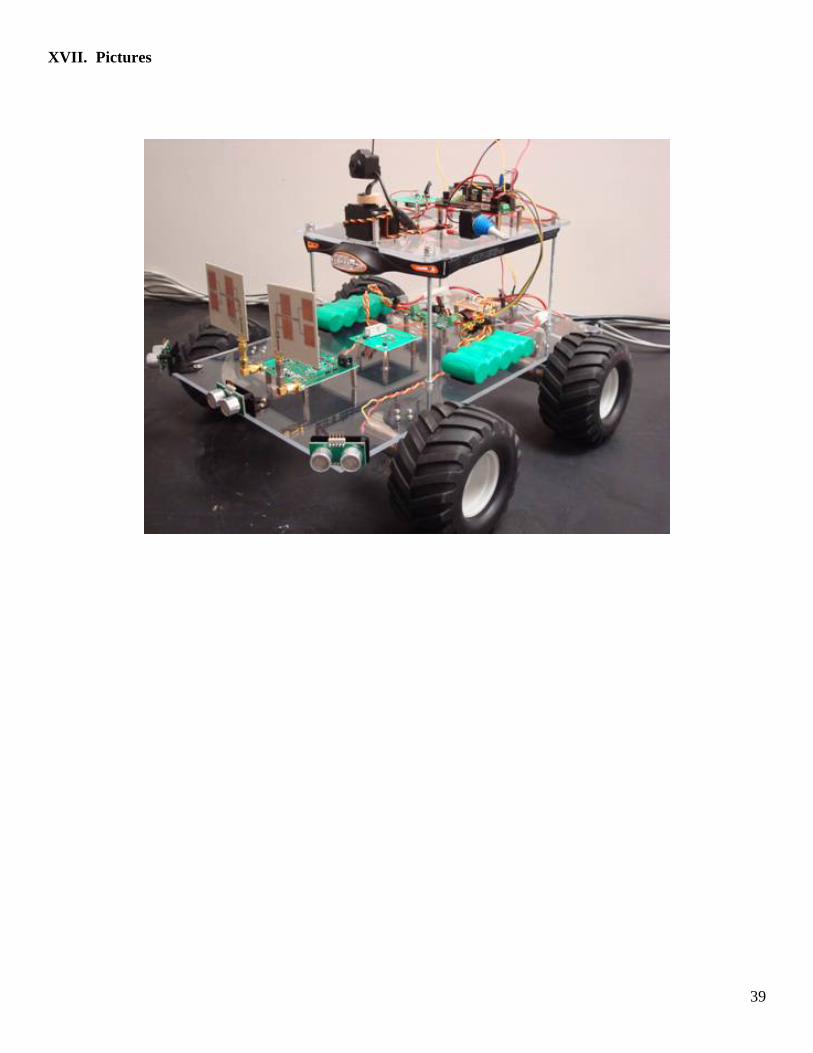
XVII. Pictures