visvesvaraya technological university jnanasangama
TRANSCRIPT

VISVESVARAYA TECHNOLOGICAL UNIVERSITY JnanaSangama, Belagavi, Karnataka-570018
Project Report on
“RIDER SAFETY SYSTEM USING EMBEDDED SYSTEM”
Submitted in partial fulfillment of the requirements for the award of the degree
Bachelor of Engineering in
ELECTRONICS AND COMMUNICATION ENGINEERING
For the academic year 2017-2018
Submitted by THULASI V 4AD14EC063
CHETHAN M 4AD13EC019
RAHID AHMED 4AD14EC442
PURUSHOTHAM N 4AD15EC447
Under the Guidance of
Dr. YATHISHA L Associate Professor
Dept. of ECE, ATMECE
ATME COLLEGE OF ENGINEERING Department of Electronics and Communication Engineering
13th Kilometer, Bannur Road, Mysuru– 570028
2017-2018

ATME COLLEGE OF ENGINEERING 13th Kilometer, Bannur Road, Mysore– 570028
Department of Electronics and Communication Engineering
CERTIFICATE
This is to certify that the project work entitled “Rider Safety System using Embedded
System” is bonafied work carried out by A R Rahid Ahmed bearing USN:4ad14ec442,
Thulasi V bearing USN:4ad14ec063, Purushotham N bearing USN:4ad15ec447,
Chethan M bearing USN:4ad13ec019 in partial fulfillment for the award of degree of
Bachelor of Engineering in Electronics and Communication of the Visvesvaraya
Technological University, Belgaum, during the year 2017-2018. It is certified that all the
corrections/suggestions indicated for internal assessment have been incorporated in the
report. The project report has been approved as it satisfies the requirements in respect of
project prescribed for the degree.
Signature of Guide Signature of HOD Signature of Principal Dr. YATHISHA L Dr. MAHESH P K Dr. L BASAVARAJ
Associate Professor Professor & HOD Principal
External Viva:
Name of the Examiners Signature with Date
1. ……………………………………… ........................................
2. ………………………………………

DECLARATION
We, Rahid Ahmed bearing USN:4ad14ec442, Thulasi V bearing USN:4ad14ec063,
Purushotham N bearing USN:4ad15ec447, Chetan M bearing USN:4ad13ec019,
studying in the final semester of Bachelor of Engineering in Electronics and
Communication Engineering at ATME College of Engineering, Mysuru, hereby declare
that this project work entitled “Rider safety system using embedded system” which is
being submitted by me in the partial fulfillment for the award of the degree of Bachelor
of Engineering in Electronics and Communication Engineering, from Visvesvaraya
Technological University, Belagavi is an authentic record of me carrying out the
prescribed project work during the academic year 2017-2018, under the guidance of
Dr. Yathisha L, Associate professor, Department of Electronics and Communication
Engineering, ATME College of Engineering, Mysuru.
I further undertake that the matter embodied in the dissertation has not been submitted
previously for the award of any degree or diploma by me to any other university or
institution.
Place: Mysuru THULASI V
Date: CHETHAN M
RAHID AHMED
PURUSHOTHAM N

ACKNOWLEDGMENT
I take this opportunity to acknowledge my profound gratitude to Dr. L. Basavaraj,
Principal, ATME college of Engineering, Mysuru for all the infrastructure and facilities
provided during my study in the institution.
I sincerely thank Dr. Mahesh P. K., Professor and HOD, Dept. of ECE, ATME college
of Engineering, Mysuru for his suggestions and support for completion of the
projectwork.
I would like to thank and place on record my deep sense of gratitude to my guide
Dr. Yathisha L Associate Professor, Dept. of ECE, ATME college of Engineering,
Mysuru for his valuable guidance, help and useful suggestions in this project work.
I would like to thank the project coordinator Dr. Prakash Kuravatti Associate
Professor, Mr. Umamahesh R. N Asst. Professor, Dept. of ECE, ATME college of
Engineering, Mysuru for his constant and valuable guidance in completing this project
work.
I express my sincere gratitude to the teaching and non-teaching staff of E&C Department
and all my friends and classmates, who helped me directly or indirectly for the successful
completion of the work.
Finally, I would like to thank my parents and all my beloved ones for supporting me in
many ways that meant a lot to me.
I

ABSTRACT
An accident is an unexpected action, which occurs in a particular situation and place.
carelessness is the major factor for such accident. The government is forcing the drivers
to wear helmet during driving. But many of them are not following the rules. We are
introducing a smart helmet system which detects that, the person wearing helmet or not
and also the system detect the person is drunk. Here we have transmitter in the helmet and
receiver at the bike. A switch will be there to ensure that the person is wearing the helmet
or not. And also an alcohol sensor is placed in the helmet near the mouth of the driver to
check whether the driver is drunk. In this system there is a switch ensures the placing of
the helmet in proper manner. we have included many other features in the system it
consist of Finger print enabled ignition key, it ensures the authorized bike owner and
protects from unauthorized persons.
II
CONTENTS
Page No
ACKNOWLEDGEMENT I
ABSTRACT II
LIST OF FIGURES IV
CHAPTER 1: INTRODUCTION 1
1.1 Litrature Survey 1
1.2 Scope of the Project 2
1.3 Problem Statement 3
1.4 Objective of the Project 3
1.5 Organisation of the Project 3
CHAPTER 2: DESIGN METHODOLOGY 4
2.1 Proposed System 5
2.2 System Design 5
2.2.1 Helmet unit 5
2.2.2 Bike unit 6
CHAPTER 3: IMPLEMENTATION AND RESULT ANALYSIS 8
3.1 Flowchart of the Proposed System 8
3.1.1 Initialisation of sensors 8
3.1.2 Fingerprint sensor flowchart 9
3.1.3 Helmet detector Flowchart 9
3.1.4 Alcohol detection sensor Flowchart 11
3.2 Result Analysis 11
3.2.1 Rider wearing helmet result 12
3.2.2 Alcohol sensor result 12
3.2.3 Fingerprint sensor result 13
3.3 Applications 14
3.3.1 Pros and Cons 14
CHAPTER 4: CONCLUSION AND FUTURE SCOPE 15
Future Scope 15
REFERENCES 16
APPENDIX 17
III

LIST OF FIGURES
Figure 2.1: Block Diagram of Proposed System 4
Figure 2.2: Circuit Diagram of Helmet unit 6
Figure 2.3: Circuit Diagram of bike unit 6
Figure 3.1: Flowchart of initialization of sensors 8
Figure 3.2: Flowchart of Fingerprint scanner 9
Figure 3.3: Flowchart of Helmet detection 10
Figure 3.4: Flowchart of Alcohol detection 10
Figure 3.5: Bike used for real time project 11
Figure 3.6: Helmet used for real time project 11
Figure 3.7: Bike and helmet module in real time 11
Figure 3.8: LCD display for invalid fingerprint 13
Figure 3.9: LCD display for valid fingerprint 13
IV

Rider safety system using embedded system 2017-2018
DEPT., of EC, ATMECE, Mysore Page 1
CHAPTER 1
INTRODUCTION
Smart helmet is used to detect alcohol consumption in the proposed project. In this we are
insisting that every bike riders must wear the helmet. The existing system is used to detect
the alcohol consumption if accident occurs the information conveyed to relative via SMS
or Short Message Service. If the driver is drunk then the engine will not get started. In
proposed method a smart helmet system which detects that, the person wearing helmet or
not and also the system detect the person is drunk. If a vehicle across this system, we are
using alcohol sensor to detect the person is drunk and we fix it in helmet. Finger print
enabled ignition key, it ensures the authorized bike owner and protects from unauthorized
persons. Hence this project is very much helpful for all the bike drivers and also the
traffic rules will be followed properly.
1.1 Literature Survey
The Author has discussed safety and security of the bikers against road accident. Smart
helmet has special idea which makes motorcycle driving safety than before this is
implemented using GSM and GPS technology. Other advantages of this project are to
measure the alcohol level of the drunken people who is riding the bike. Whenever the
alcohol level crosses the predefined value, the alarm starts and gets notification about the
drunken driver. The author have also discussed about the accident detector and the sensor
will active the GPS and find the location and further SMS will send to ambulance or
family members.
According to the author this project is specially developed as to improve the
safety of the motorcycle’s rider. The objective of this project is to study and understand
the concept of RF transmitter and RF receiver circuit. The project uses ARM7, GSM and
GPS module. The project also uses buzzer for indication purpose. This project is only
concentrated on only one specific purpose that is an accident. Whenever the accident will
occur then accident spot will be note down and information will send out on the noted
mobile number [1].
The major disadvantage of this project paper is they are not using any display
device for showing the current status. Also the cost of helmet is still high since helmet is

Rider safety system using embedded system 2017-2018
DEPT., of EC, ATMECE, Mysore Page 2
designed for only one purpose. In this paper author has discussed on the speed of the
vehicle. In this application the project will be monitoring the areas in which the vehicle
will be passing. On entering any cautionary areas like schools, the speed of the vehicle
will be controlled to a predefined limit. He worked on the phenomenon of speed of
vehicle along with some security factor. LCD is used for showing the various types of
messages after wearing the helmet. The author has worked only on the phenomenon of
accident which is generally happens due to drink and drive. But as we know that the
accident in the area is not happens only due to consuming alcohol but also other
parameters are also responsible [2].
In this paper the prime objective of author is to force the rider to wear the helmet
throughout [3]. Considering the increasing number of motorcycle riders in our country
and the number of accident happening each year.
In this competitive world one of the surveys says that the death tolls due to motor
bike accidents are increasing day by day out of which most of these casualties occurs
because of the absence of helmet. Traffic police cannot cover remote roads of city. That’s
why over primary target is to make the usage of the helmet for two wheelers compulsory.
Thus no one other than the owner himself, who doesn’t have password which would have
been created by the owner, can use the bike.
The other this module basically deals with the checksum of rider if he is wearing
the helmet or not on first place to achieve this ultrasonic sensor is been used .based on
this the signal are been sent to the next module voice recognition module use for
authentication purpose. Arduino is also used in this project which is an open source tool
for making computer that can sense and control more of physical world than your desktop
computer [4].
1.2 Scope of the Project
Nowadays more accidents are happening by drink and driving. It caused severe head
injuries for not wearing helmet. Therefore we implemented alcohol detection using smart
helmet. We use fingerprint scanner which provides anti-theft to vehicles and liquid crystal
display (LCD) for displaying the message.
And also GSM modem as an interface between mobile and Arduino. It will send
message to any phone irrespective of the GSM network through the modem connected to
the programmable device.

Rider safety system using embedded system 2017-2018
DEPT., of EC, ATMECE, Mysore Page 3
1.3 Problem Statement
In the current system, government traffic rules and regulations are not followed by the
peoples, this may cause accidents and the injury or death of the peoples. Let the rider
safety we will assume as variable(Y) and government traffic rules that to be followed be
(Z), this both variables will give the existing system output(X).
X=Y*Z (1.1)
Here the rider safety is dependent (*) on the traffic rules that are followed and checked
manually in equation (1.1) , hence if the rider follows the traffic rules and regulations
then the safety riding is achieved.
X=Y+Z (1.2)
In the equation (1.2) the rider safety is not dependent on the factor Z, The output of this
system are addition of both the variables and the rider safety measures are automated by
the proposed system(rider safety system using embedded system).
1.4 Objective of the project
The objective of project is to design intelligent helmet system which ensures
wearing of helmet and prevent switching ON bike if rider is under influence of
alcohol throughout the ride.
The system detects accident and intimate relatives via SMS.
In addition it protects bikes from being stolen fingerprint scanner is used to start
ignition system of bike.
1.5 Organization of the report
The report is divided into 4 chapters.
Chapter 1 describes about the problem statement and Objective of the” Drive Protection
& safety using Intelligent Wireless Safety Helmet” and literature review
Chapter 2 describes about Design methodology.
Chapter 3 describes the implementation and result analysis
Chapter 4 describes about conclusion and scope for future.

Rider safety system using embedded system 2017-2018
DEPT., of EC, ATMECE, Mysore Page 4
CHAPTER 2
DESIGN METHODOLOGY
Every person must wear a helmet while travelling by motorcycle or two-wheeler. Road-
traffic accidents are a major cause of premature death and disability all over the world
and motorized two wheelers account for the majority of such cases, particularly, in the
developing countries like India where they are most convenient mode of transportation.
Head, face injuries are leading causes of death due to motorcycle crashes.
Despite of the availability of substantial evidence that safety helmets are effective
in reducing the incidence and severity of head injuries, people are reluctant to use helmet.
In recent years, mandatory helmet use for motorcyclists has received a considerable
attention across the country. However, effective enforcement of law, rules & regulations
regarding mandatory use of helmet is limited to metro cities and urban areas. To solve the
problem different methods have been designed, which can be classified into rule-based,
physical-model-based and machine learning-Technique - based methods. Rule-based
methods are the most commonly used ones. Figure 2.1 shows the block diagram of the
proposed system.
Figure 2.1: Block diagram of proposed system.
Arduino UNO
Alcohol
detector sensor
Helmet on head
detector
Finger print
scanner LCD Display
Ignition
control unit
GSM Module

Rider safety system using embedded system 2017-2018
DEPT., of EC, ATMECE, Mysore Page 5
2.1 Proposed System
The proposed system is an intelligent helmet. The system ensures the safety of the biker,
by making it necessary to wear the Helmet, as per the government guidelines, also to get
proper and prompt medical attention, after meeting with an accident. A module is affixed
in the helmet, such that, the module will sync with the module affixed on the bike. The
system will bear following functionalities:
● It will ensure that the rider has worn the helmet. If he fails to do so, the bike won’t start.
● It will also ensure that biker has not consumed alcohol. If the rider is drunk, the bike
won’t start.
● It will ensure that the rider fingerprint is matching with the image captured in memory
of fingerprint sensor. If it matches bike will start or if it is not matched then bike won’t
get start. .
It will consist of two parts:
• Module on helmet
• Module on the bike.
Data from the helmet will be transmitted wirelessly to the bike. According to the various
sensor input the micro-controller will decide the actions of other blocks.
2.2 System Design
The system consists of two parts: Helmet unit and Bike unit
2.2.1 Helmet unit
This unit basically consists of a Pressure Sensor, Alcohol Sensor, Arduino Nano and
Transmitter. Pressure Sensor: Pressure sensor is switch which is used in helmet. The
LOW or HIGH output of the Pressure sensor determines if the helmet is worn or not
worn. Alcohol Sensor: Used for detecting alcohol concentration in breath. It provides an
analog output based on alcohol concentration. If the amount of alcohol exceeds the
threshold value it will not allow the bike to start. Arduino Nano: All the analog outputs
from all the sensors on the helmet are sent to this Arduino Nano as input. According to
the threshold set for alcohol sensor, high output of the pressure sensor, a decision is made
and sent to the module on bike wirelessly. Transmitter: A RF transmitter operating at 433
MHz Radio Frequency is used to transmit the serial data to the receiver over wireless
media. Figure 2.2 shows the circuit of the Helmet unit.
Rider safety system using embedded system 2017-2018
DEPT., of EC, ATMECE, Mysore Page 6
Figure 2.2: Circuit Diagram of Helmet unit
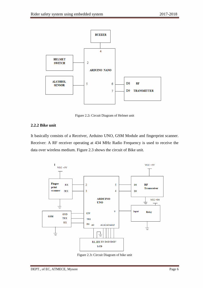
2.2.2 Bike unit
It basically consists of a Receiver, Arduino UNO, GSM Module and fingerprint scanner.
Receiver: A RF receiver operating at 434 MHz Radio Frequency is used to receive the
data over wireless medium. Figure 2.3 shows the circuit of Bike unit.
Figure 2.3: Circuit Diagram of bike unit
Rider safety system using embedded system 2017-2018
DEPT., of EC, ATMECE, Mysore Page 7
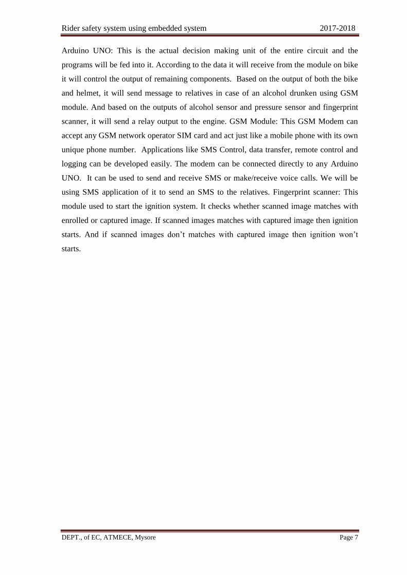
Arduino UNO: This is the actual decision making unit of the entire circuit and the
programs will be fed into it. According to the data it will receive from the module on bike
it will control the output of remaining components. Based on the output of both the bike
and helmet, it will send message to relatives in case of an alcohol drunken using GSM
module. And based on the outputs of alcohol sensor and pressure sensor and fingerprint
scanner, it will send a relay output to the engine. GSM Module: This GSM Modem can
accept any GSM network operator SIM card and act just like a mobile phone with its own
unique phone number. Applications like SMS Control, data transfer, remote control and
logging can be developed easily. The modem can be connected directly to any Arduino
UNO. It can be used to send and receive SMS or make/receive voice calls. We will be
using SMS application of it to send an SMS to the relatives. Fingerprint scanner: This
module used to start the ignition system. It checks whether scanned image matches with
enrolled or captured image. If scanned images matches with captured image then ignition
starts. And if scanned images don’t matches with captured image then ignition won’t
starts.

Rider safety system using embedded system 2017-2018
DEPT., of EC, ATMECE, Mysore Page 8
CHAPTER 3
IMPLEMENTATION AND RESULT ANALYSIS
A flow chart is a pictorial representation of a process using different symbols containing
information about steps or sequence of events. Each of these symbols is linked with
arrows to illustrate the flow direction of the process. The flowchart describes the
functionality of the Accident Detection, Intelligent Wireless Safety Helmet. The helmet
unit continuously checks Helmet wearing and Alcohol sensing. If condition is met then
helmet unit sends amative signal to vehicle unit through Arduino. And also checks the
scanned image with the captured image of the fingerprint scanner to start ignition system.
If it is matched ignition turns ON. Thereafter, vehicle starts/keep moving.
3.1 Flowchart of the Proposed System
Flowchart of the proposed system explains the functionalities of the sensor process.
Sensor process is explained for different sensor.
3.1.1 Initialisation of sensors
Figure 3.1: Flowchart of initialization of sensors
Here it initializes all the sensor required for ignition system to start. Firstly it initializes
alcohol and helmet sensor. After satisfying the conditions of alcohol and helmet sensor,
Fingerprint scanner is initialized to start ignition system. Figure3.1 shows the
initialization the sensor.
Start
Initializing the sensor
Finger
scanner
Alcohol
detection
Helmet
detection

Rider safety system using embedded system 2017-2018
DEPT., of EC, ATMECE, Mysore Page 9
3.1.2 Fingerprint sensor flowchart
Here Fingerprint scanner checks whether captured fingerprint image matches with the
scanned image while starting the ignition system. If scanned image doesn’t match with
the captured image then, ignition system turns OFF or if scanned image matches with
captured image then, ignition system turns ON. Figure 3.2 shows the flow diagram of
finger print sensor.
Not matched
Matched
Figure 3.2: Flowchart of Fingerprint sensor
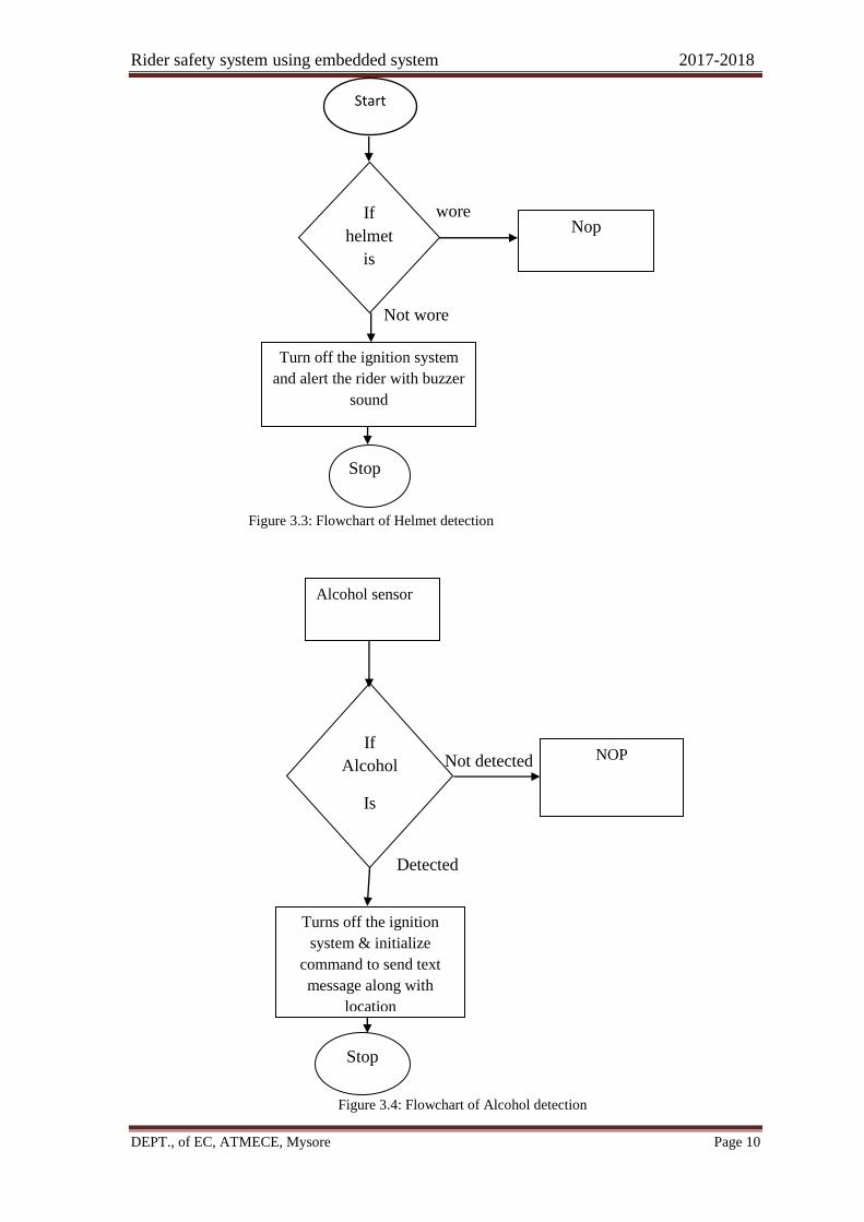
3.1.3 Helmet detector Flowchart
Here Firstly, helmet sensor senses whether rider wearied helmet or not. If rider has not
worn the helmet then ignition system won’t turn ON. If rider worn helmet it send message
to Arduino to turn ON ignition system.
Sensing of helmet is done switch used is pressed when helmet worn, and sends
sensed digital data. Figure 3.3 shows the flow diagram of helmet sensor.
Finger print sensor
Ignition system
turns on & battery
power supply on
Again check with
received image Captured
image
Rider safety system using embedded system 2017-2018
DEPT., of EC, ATMECE, Mysore Page 10
wore
Not wore
Figure 3.3: Flowchart of Helmet detection
Not detected
Detected
Figure 3.4: Flowchart of Alcohol detection
Alcohol sensor
Turns off the ignition
system & initialize
command to send text
message along with
location
NOP If
Alcohol
Is
Stop
If
helmet
is
Turn off the ignition system
and alert the rider with buzzer
sound
Stop
Nop
Start

Rider safety system using embedded system 2017-2018
DEPT., of EC, ATMECE, Mysore Page 11
If alcohol is detected in rider breath then, ignition system won’t turn ON. If alcohol is not
detected in rider breathe then, ignition system turn ON. Figure 3.4 shows the flow
diagram of alcohol sensor.
3.2 Result Analysis
Here it explains results obtained by different sensor .Figure 3.5 and figure 3.6 shows the
Bike and helmet used for real time project.
Figure 3.5: Bike used for real time project
Figure 3.6: Helmet used for real time project
This above figure shows the alcohol sensor fixed in the helmet module for the detection
of alcohol consumption of the rider and this output of alcohol sensor is received by the
Arduino nano and sends the corresponding signal to the ignition unit by the transmitter
used in it, then the ignition module receives the signal and sends the text message to the
respected guardians or the nearest RTO as described on the programming.
Helmet used for the
real time application
of proposed system
Alcohol sensor fixed
on the helmet for
detection of rider
alcohol consumption

Rider safety system using embedded system 2017-2018
DEPT., of EC, ATMECE, Mysore Page 12
Figure3.7:Bike and helmet module in real time
Figure 3.7 shows the Bike and helmet module in real time which explains the result
obtained by different sensors.
3.2.1 Rider wearing helmet result
With the help of pressure sensor, driving without helmet can be avoided. Pressure sensor
senses the pressure of wearing helmet, here output may be high or output is low. If output
is high then rider is wearing helmet and vice-versa.
When helmet is worn buzzer won’t make sound indication. If helmet is not worn
then buzzer makes sound indication.
3.2.2 Alcohol sensor result
Illegal consumption of alcohol during driving is 0.08 mg/L as per the government act but
for demonstration purpose, it is programmed to the threshold limit 0.04 mg/L. If
sensitivity of MQ-3 is more than 0.04 mg/L of alcohol in breath then Arduino of Helmet
unit will communicate with vehicle unit and show “Alcohol detected ” thereafter ignition
system get switched OFF.
When alcohol is not consumed there will no message sent to the prescribed
number using GSM, and it allows fingerprint to access When alcohol is consumed there
will message sent to the prescribed number using GSM, and it not allows fingerprint to
access.
3.2.3 Fingerprint sensor Result
The motorcycle will be ignited only when the authorized person scans his/her finger on
the fingerprint module. The fingerprints of the authorized person(s) are stored in the
Ignition unit
and helmet
interfaced to
bike in real
time.

Rider safety system using embedded system 2017-2018
DEPT., of EC, ATMECE, Mysore Page 13
fingerprint module. When any person put his/her finger on the fingerprint module then the
data of the placed finger is matched with the stored data in the module. If the fingerprint
data is found in the module matching the condition, then Arduino ignites the bike
otherwise bike will not start. Figure 3.8 describes that, when there is consumption of
alcohol and when rider is not wearing helmet fingerprint will not be accessed. Then it
display as “No valid finger on the sensor”.
It also describes that, if the scanned fingerprint image doesn’t matches with
enrolled/captured image, then LCD displays as “No valid finger on the sensor”. Then bike
ignition will not start.
When there is no consumption of alcohol and when rider worn helmet fingerprint will be
accessed. If the scanned fingerprint image matches with enrolled/captured image, LCD
displays as “welcome”. Figure 3.9 describes that, when there is no consumption of
alcohol and when rider is wearing helmet fingerprint will be accessed. Then it display as
“Welcome”.It also describes that, if the scanned fingerprint image matches with
enrolled/captured image, then LCD displays as “Welcome”. And bike ignition will start
and while running whenever the helmet is removed or the alcohol consumption is
detected on the helmet then the respected signal will transmit to the ignition unit and the
ignition will turn’s off the bike.
Figure represents that, bike
ignition will not start, when
fingerprint is accessed without
satisfying the conditions.
Figure represents that, when
finger print is not accessed
LCD displays “No valid
finger on the sensor”.

Rider safety system using embedded system 2017-2018
DEPT., of EC, ATMECE, Mysore Page 14
Figure 3.9: LCD display for valid Fingerprint
3.3 Applications
1. Metro cities and urban areas to avoid the accidents and to follow traffic rules.
2. Used in the cities where rules breaking traffic is more.
3.3.1 Pros and Cons
Pros
1. Automated safety measures for the vehicle riders.
2. Unauthorized person cannot drive the vehicle.
3. Can be used for the other high motor vehicles by implementing this system.
4. Accidents caused by drink and drive are avoided.
5. Other features can be added on this system.
Cons
1. The cost of the helmet is increased.
2. Additional features are added hence the cost of vehicle is increased.
Figure represents that, bike
ignition start, when
fingerprint is accessed
after satisfying the
conditions.
Figure represents that, when
fingerprint is accessed. LCD
displays “welcome”.
Rider safety system using embedded system 2017-2018
DEPT., of EC, ATMECE, Mysore Page 15
CHAPTER 4
CONCLUSION AND FUTURE SCOPE
This system was designed majorly to avoid motor bike accident. The accidents are
increased majorly due to absence of helmet or the usage of alcoholic drinks so the major
objective of this system is to develop an electronic smart helmet system. This system
sequent checking the helmet wearing and drunken driving. By implementing this system
we can reduce head injuries occur offend. It helps the driver to control vehicle easily. And
it is most economical and easy to use. So it has good social aspects
Future Scope
In future if there is a large demand of this type of helmets we can manufacture the whole
circuit in printed circuit board, so that circuit becomes smaller and can be easily fitted
into helmet. The circuit can also be powered by solar energy so that it uses green energy
and does no harm to environment .The flexible solar panels can fixed all along surface of
helmet. This type of helmet technology can be implemented for the combat helmets used
by the soldiers working under extreme temperatures.

Rider safety system using embedded system 2017-2018
DEPT., of EC, ATMECE, Mysore Page 16
REFERENCES
[1] Vijay Savania, Hardik Agravata, and Dhrumil Patela, “Alcohol Detection and Accident Prevention of
Vehicle”, IJIERE, Volume 2, Issue 3, 2015, PP 55-59.
[2] Ashish Manwatkar, Irfan Patil, Jayraj Tekale, Vinayak Kamble, Nikhil Gotur “Automatic traffic
accident detection and alarm system” International Journal of Technological Exploration and Learning
(IJTEL) Volume 1 Issue 1 (August 2012), pp 30-32.
[3] Sri Krishna Chaitanya Varma, Poornesh, Tarun Varma, Harsha, “Automatic Vehicle Accident Detection
And Messaging System Using GPS and GSM Modems “, International Journal of Scientific & Engineering
Research, Volume 4, Issue 8, August-2013, pp 1937-1940.
[4] A.Sriram and P.Ramya “Automatic accident notification system using GSM and GPS modems with 3g
technology for video monitoring” International Journal of Emerging Trends in Electrical and Electronics
(IJETEE) Vol. 1, Is-sue. 2, March-2013, pp 11-13.
[5] “Vehicle accident alert and locator” International Journal of Electrical & Computer Sciences IJECS-
IJENS Vol: 11 No: 02, April 2011
[6] J.Vijay, B.Saritha, B.Priyadharshini, S.Deepeka, R.Laxm, “Drunken Drive Protection System”,
IJSER ,Volume 2, Issue 12, December 2011, PP2229-5518 12
[7] Kavita, Alok Srivastava, “Identification of intoxicated drivers using GSM”, International Journal of
Engineering & Scientific Research, IJESR Volume 2, Issue 10, October 2014, pp 2347-6532.
[8] Elie Nasr, Elie Kfoury, David Khoury, “An IoT Approach to Vehicle Accident Detection, Reporting,
and Navigation”, IEEE 978-1-5090-5281,2016
[9] Wang Wei, Fan Hanbo― “Traffic Accident Automatic Detection And Remote Alarm Device” IEEE
978-1-4244-8039- 5/11/2011.
[10] Yue –Cheng Wu, Yun-qing Xia &, Zhejiang, “Multichannel reflective PPG earpiece sensor With
passive motion cancellation‖ Biomedical Circuits &System”, IEEE, vol 2, issue 10, 2007, PP 235-241.