visual inertia tn apparent motion - stuart anstis...
TRANSCRIPT

Virion Rts. Vol. 27, No. 5, pp. 755-764, 1987 0042~6989187 $3.00 + 0.00 Pkmd in Great Britain. Ail rights reserved Copyright 0 1987 Pcrgamon Journals Ltd
VISUAL INERTIA TN APPARENT MOTION
STUART ANSTIS
Department of Psychology, York University, 4700 KeeJe St., Downsview, Ontario, Canada M31 IP3
and
V. S. RAMACHANDRAN
Department of Psychology, University of California at San Diego, La Jolla, CA 92093, U.S.A.
(Received 9 September 1985; in revised firm 22 September 1986)
Abstract-Four dots in an imaginary diamond were flashed in succession to give ambiguous apparent motion (AM). The top and bottom dots were flashed at time t, and replaced by the left and right dots at time t,. If two priming dots were gashed beforehand at time r0 in line with two parallel sides of the diamond, AM was seen along those sides. We call this “visual inertia”. The amount of visual inertia (measured by a null method) fell off with increasing angle between the priming dot and the side of the diamond. Visuai inertia was stih seen when the priming dots were presented to one eye and the test dots to the other, so the effect must be partly central. The timing and length of the priming path made little difference to visual inertia. However, static priming dots were ineffective. We conclude that the visual system was examining at least three successive time frames in deciding which items in one frame correspond with which items in succeeding frames.
Movement perception Apparent motion Psychophysics Correspondence problem
A dot which jumps back and forth between two positions at suitable temporal and spatial inter- vals will be seen in apparent motion (AM). Figure l(a, b) show four dots forming an imag- inary diamond. The north and south dots are flashed on at time 1 and are replaced by the east and west dots at time 2, and this cycle repeats continuously. The apparent motion produced by this display is ambiguous, since it is equally likely to occur in a northeast-southwest direc- tion [Fig. l(a)] as in a northwest-southeast direction [Fig. l(b)]. We did not use dots ar- ranged in a square with horizontal and vertical sides. Gengerelli (1948) noted that with this configuration subjects favoured vertical motion; probably because of a reluctance to see AM across the vertical midline of the retina.
We have used this four-dot stimulus to ex- plore the factors which influence AM (Rama- chandran and Anstis, 1983a). In particular we have described an effect which we called “visual inertia” (Rama~handran and Anstis, 1983b). If the quartet of dots was embedded in two straight parallel rows of dots which were flashed on in succession, there was a strong tendency to see AM in the direction of the embedding
motion. Rows of stutic dots had no such effect, Eggleston (1984) has also investigated similar phenomena. We have used the expression “priming dots” to refer to the dots flashed before or after the dots in the quartet and which potentially alter their AM, and the expression “test dots” to refer to the quartet of dots.
EXPERih¶ENT 1
Angular Function of Visual Inertia
Ramachandran and Anstis (1983b) reported visual inertia when two rows of six priming dots were aligned with the sides of the diamond of test dots. In the present study we used a pair of priming dots pre~nted just before the test dots [Fig, l(c, d)] and found that this sufficed to produce visual inertia. Using a nulling staircase method, we measured visual inertia as a func- tion of the priming angle A. The priming angle was designated zero when the two priming dots were above and below the diamond, in line with its vertical diagonal [Fig. 2(a)]. Under these conditions the display was symmetrical and the priming dots could therefore not favour either of the two possible AM paths. Visual inertia was thus not seen. However, when the priming dots
755

756 STUART ANSTIS and V. S. RAMACHANDRAN
a b
d
Fig. 1. Two dots were flashed up at the top and bottom comers of an imaginary diamond, then replaced by two dots at the left and right comers. This ambiguous stimulus gave apparent motion (AM), which could look either as in (a) or as in (b), in which solid arrows show direction of perceived apparent motion. Numbers inside spots indicate time of presentation; actual spots were tiny luminous dots. (c, d) When these dots were preceded by two priming dots at time t,,, the AM was seen along the axes of the priming dots (solid arrows). We call this effect “visual inertia”. Priming angle A = +45” in (c), -45” in (d). i = priming path; j. k are alternative paths the AM could take. Inertia was measured by altering the separation j. increasing it in condition (c) and reducing it in condition (d), until AM in both directions was equiprobable. Thus proximity, which favours AM, was
titrated against visual inertia.
were aligned with the upper left and lower right sides of the diamond (A = +45”), they strongly favoured motion along these two sides [Fig. l(c)]. Similarly, when the dots were aligned with the lower left and upper right sides of the diamond (A = -45) they strongly favoured AM along these two sides [Fig. l(d)]. We measured visual inertia over a range of priming angles A from - 112.5 to + 112.5” in steps of 22.5”.
We also varied the shape of the diamond. The “medium” diamond was square with its sides making an angle of +45” to the vertical. The “narrow” diamond was a tall rhombus with sides at an angle of f22.5” to the vertical. The “wide” diamond was a squat rhombus with sides at an angle of f67.5” to the vertical. The height : width aspect ratios of the diamonds were 1: 1, 2.4: 1 and 1:2.4 respectively. (The wide diamond was simply the narrow diamond laid on its side: both had corner angles of 45 and 135”.) The sides of all diamonds were 1.5 deg of visual angle in length. Thus 33 conditions were explored: eleven priming angles x three dia- mond shapes. Figure 2 illustrates examples of three conditions. The number inside each dot shows the time at which it was presented, thus the priming dots were flashed at time r0 and the dots in the quartet at times t, and tz. The solid arrows show the AM path which was reinforced by the priming dots. In Fig. 2(a) the diamond was medium and the priming angle was 0” (vertical), not favouring AM in either direction. Figure 2(b) shows a narrow diamond and a priming angle of +90”, so the priming dots
- 22.5 ’ +90°
Q
a b C
Fig. 2. Examples of the stimuli used in Experiment I. Solid arrows show direction of AM which was promoted by the priming dots. (a) Medium (square) diamond. Riming angle A = 0”. (b) Narrow diamond.
Priming angle = +90”. (c) Wide diamond. Priming angle = -22.5”.

Visual inertia in apparent motion 757
moved along horizontal trajectories from upper right and lower left, while Fig. 2(c) shows a wide diamond and a priming angle of -22.5”.
The strength of visual inertia was measured by a nulling method. It is well known that proximity favours AM; when a dot at time f, is replaced at time rz by a nearby dot and a distant dot, AM is more likely to be seen toward the nearer dot (Ullman, 1979; Mather and Anstis, 1987). Using a method we have described else- where (Ramachandran and Anstis, 1983b) we used proximity to oppose, or back off, the inertia. In Fig. l(c), visual inertia produced by the priming path i favoured AM along the left hand path j, so we increased the distance j, keeping the distance k constant, until both AMs were equally probable. In Fig. l(d), visual in- ertia favoured AM along the right hand path k, so we shortened j, keeping k constant, until once again both AMs were equally probable. The ratio of j to k gave a measure of the strength of visual inertia. These operations changed the square diamond into a rectangle and the rhom- bic diamonds into parallelograms, but did not alter the angles at the comers of the diamonds.
Method
Five subjects were run, the first author (S.M.A.) and four practised subjects who were naive as to the intent of the experiment. The subject viewed a 12-in. t.v. monitor screen from a distance of 57 cm. The display was controlled by a microcomputer. A diamond shape (narrow, square or wide) was preselected for each run and then the eleven priming angles were presented in a random order selected by the computer. The priming path i and the sides j, k of each dia- mond of dots initially subtended 1.5 deg of visual angle, and the stimulus onset asynchrony (SOA) between successive dots was 166 msec. The stimulus was presented as a one-shot, not a repetitive cycle; the priming dots were flashed up at time to and were replaced 166 msec later by the north and south dots at time t,, and after another 166 msec by the east and west dots at time t2, The subject hit key “1” on the keyboard if he saw NE-SW motion along path j and key “2” if he saw NW-SE motion along path k. It was arranged that hitting key “1” lengthened path j, making NE-SW motion less probable, and hitting key “2” shortened path j, making NW-SE motion less probable. Paths i and k were kept constant at 1.5 degrees of visual angle. This negative feedback arrangement con- trolled a staircase procedure. Each staircase
+cTO 40 ( \ /
SO’ l /
\
20’ /
10’.
\ / l - A
(a) V
Fig. 3. Results of Experiment 1: angular function of visual inertia. Direction and distance of each datum point from the top comer of the diamond represent a priming angle and the resulting amount of visual inertia, expressed as the per- centage difference between the sides j and k of the diamond. Radial bars represent + 1 SE. (a) Narrow diamond: (b) square diamond: (c) wide diamond. The asterisk in (b) shows that sroric priming dots were ineffective, producing
only about 7% visual inertia (Experiment 5).
comprised 8 reversals and the average of the last 6 reversals was taken as the path ratio which nulled out the subject’s visual inertia. The ratio calculated was lOO* (j - k)/k, which gives the percentage difference between j and k.
Results
The angular functions, or directional tuning curves, of visual inertia are shown in Fig. 3. They form petal-shaped lobes in which the direction of each datum point from the top comer of the diamond represents the priming angle, and the distance from each datum point to the comer represents the amount of visual inertia, expressed as the percentage difference between paths j and k at the null setting. Percentage markers are shown. Radial bars represent 4 1 SE. Results have been combined

758 STUART ANSTIS and V. S. RAMACHANDRAN
for priming paths to the left (A < 0) and right (A > 0) of the vertical. Each datum point is the mean of 30 readings (six 6-reversal staircases x five subjects).
In Fig. 3, smooth curves have been fitted by eye to the data points. The lobes for the narrow diamond [Fig. 3(a)] were larger and oriented more toward the vertical than for the wide diamond [Fig. 3(c)]. The lobes for the medium diamond [Fig. 3(b)] were intermediate in shape and size. The overall mean visual inertias for the narrow: square : wide rectangles were in the ratios 1.63: 1.45: 1. In each case the half- amplitude half-bandwidth of these directional tuning curves was about 45”. The lobes were not symmetrical about the axis which is aligned with the sides of the diamond, but were skewed anticlockwise from this orientation. We attri- bute this skewing to interactions from the com- peting lobe (not shown in Fig. 3, but positioned to the right of the diamond) which favours the rival direction of AM. For instance, a lobe cannot extend to the right of vertical, since any priming path to the right of vertical will re- inforce path j instead of path k. Thus the curve may represent an “excitatory” inertia effect, minus an “inhibitory” competition from the other lobe.
EXPERIMENT 2
Interocular Transfer of Visual Inertia: Monocular us Dichoptic Priming
In order to investigate the neural site of visual inertia we presented the priming dots to one eye, and the quartet of test dots to the other eye. In the control condition all dots were presented monocularly to the same eye.
The same eleven priming angles were used, together with the medium (square) diamond. Conditions were the same as in the previous experiment except that two copies of the stimu- lus were presented side by side on the t.v. screen, one for each eye, and fused binocularly by free fusion. Three subjects, who were practised at free fusion, were used. To aid fusion, the left and right eye’s stimuli were each surrounded by an outline frame which was 5.6” wide and 6.2” high.
Four separate staircases were each presented twice to each subject, in a randomized order. The conditions for the staircases were:
Condition 1. 2. 3. 4.
Results
Priming dots Test dots Left eye Left eye Right eye Right eye Left eye Right eye Right eye Left eye
Qualitative: the subjects reported that the monocular and dichoptic conditions looked similar. The apparent motion looked equally convincing, and it was not obvious upon casual inspection whether a given trial was monocular or dichoptic. This is consistent with the finding of Shipley, Kenney and King (1945) and of Ammons and Weitz (1951) that AM can be elicited by flashing one dot to one eye and a displaced dot to the other. These authors did find, however, that dichoptic AM was some- what less salient than monocular AM.
Quantitative results are shown in Fig. 4. The results for the monocular conditions 1 and 2 were averaged together, and so were the results for the dichoptic conditions 3 and 4. Also the results for left and right priming paths have been combined. Thus each datum point in Fig. 4 is the mean of 24 readings (eight 6-reversal staircases x three subjects). In Fig. 4 the overall mean of the dichoptic inertia was 74% of the overall mean monocular inertia. Thus, visual inertia was about three quarters as strong when the priming and test dots were presented to different eyes as when they were presented to the same eye. This high degree of interocular trans- fer suggests that the site of visual inertia lies at least partly in the binocular pathways, central to the point of binocular fusion.
Fig. 4. Results of Experiment 2: monocular vs dichoptic visual inertia. Same conventions as Fig. 3. l = monocular (priming and test dots presented to the same eye), 0 = dichoptic (priming dots presented to one eye, test dots to the other eye). Dichoptic priming gave 74% as much inertia as monocular priming did, suggesting that inertia lies
central to the point of binocular fusion.
Visual inertia in apparent motion 759
EXPERIMENT 3
Visual Inertia is Independent of Priming Path Length
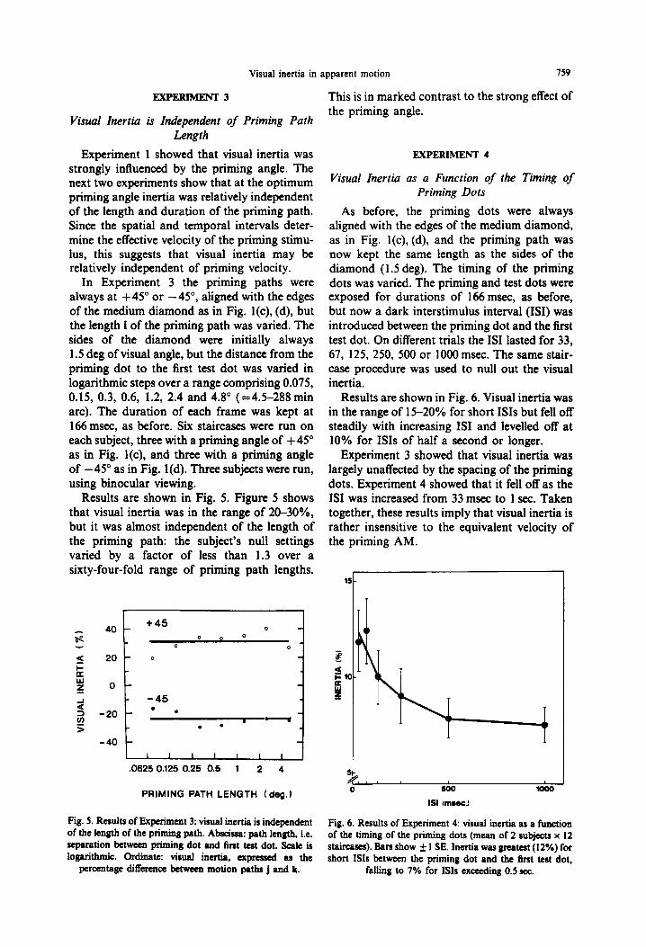
Experiment 1 showed that visual inertia was strongly influenced by the priming angle. The next two experiments show that at the optimum priming angle inertia was relatively independent of the length and duration of the priming path. Since the spatial and temporal intervals deter- mine the effective velocity of the priming stimu- lus, this suggests that visual inertia may be relatively independent of priming velocity.
In Experiment 3 the priming paths were always at +45” or -45”, aligned with the edges of the medium diamond as in Fig. l(c), (d), but the length i of the priming path was varied. The sides of the diamond were initially always 1.5 deg of visual angle, but the distance from the priming dot to the first test dot was varied in logarithmic steps over a range comprising 0.075, 0.15, 0.3, 0.6, 1.2, 2.4 and 4.8” (=4.5-288min arc). The duration of each frame was kept at 166 msec, as before. Six staircases were run on each subject, three with a priming angle of +45” as in Fig. l(c), and three with a priming angle of -45” as in Fig. l(d). Three subjects were run, using binocular viewing.
Results are shown in Fig. 5. Figure 5 shows that visual inertia was in the range of 20-30%, but it was almost independent of the length of the priming path: the subject’s null settings varied by a factor of less than 1.3 over a sixty-four-fold range of priming path lengths.
r 1
5 20 0
k Y 0 a
t
-45
l 2 -20 l . d 6 . l
-40
I I I I I I I 1 ,
0625 0.125 0.25 0.5 1 2 4
PRIMING PATH LENGTH (deg.)
Fig. 5. Results of Experiment 3: visual inertia is independent of the length of the priming path. Abscissa: path length, i.e.
Fig. 6. Results of Experiment 4: visual inertia as a function
separation between priming dot and first test dot. Scale is of the timing of the priming dots (mean of 2 subjects x 12
logarithmic. Ordinate: visual inertia, expressed as the staircases). Bars show * 1 SE. Inertia was greatest (12%) for short ISIS between the priming dot and the first test dot,
percentage difference between motion paths j and k. falling to 7% for ISIs exceeding 0.5 sec.
This is in marked contrast to the strong effect of the priming angle.
EXPERIMENT 4
Visual Inertia as a Function of the Timing of Priming Dots
As before, the priming dots were always aligned with the edges of the medium diamond, as in Fig. l(c), (d), and the priming path was now kept the same length as the sides of the diamond (1.5 deg). The timing of the priming dots was varied. The priming and test dots were exposed for durations of 166 msec, as before, but now a dark interstimulus interval (ISI) was introduced between the priming dot and the first test dot. On different trials the IS1 lasted for 33, 67, 125, 250, 500 or 1000 msec. The same stair- case procedure was used to null out the visual inertia.
Results are shown in Fig. 6. Visual inertia was in the range of 15-20% for short ISIS but fell off steadily with increasing IS1 and levelled off at 10% for ISIS of half a second or longer.
Experiment 3 showed that visual inertia was largely unaffected by the spacing of the priming dots. Experiment 4 showed that it fell off as the IS1 was increased from 33 msec to 1 sec. Taken together, these results imply that visual inertia is rather insensitive to the equivalent velocity of the priming AM.
$, , , 0 a00 loo0
ISI Imr0c.l

760 STUART ANSTIS and V. S. RAMACHANDRAN
EXPERIMENT 5
Control Condition: No Inertia From Static Priming Dots
The conditions were the same as for Experi- ment 4, except that now the priming dots were static and always visible. Three subjects took part. The priming dots were positioned at either +45”, as in Fig. l(c), or at - 45”, as in Fig. l(d). Results: there was virtually no sign of visual inertia. The null setting (mean of 12 settings x three subjects) was 7%. This setting, which is shown as an asterisk in Fig. 3, was only about one-fifth of the visual inertia obtained with dynamic priming dots (Fig. 3). This shows that visual inertia was not merely a Gestalt-like Einstellung or tendency to see static dots as apparently lying in a straight line. Instead it was truly a dynamic effect.
were arranged in a zigzag and exposed in se- quence. Each frame duration was 125 msec and the separation between neighbouring dots was 1.5’. Zigzagging of the test dots was never seen. Instead, the test dots moved in a direction collinear with the last pair of priming dots, and all the earlier dots were ineffective. Thus we found no evidence that inertia is an Einstellung phenomenon.
Inertia does not seem to be a Gestalt-like expectation (set or Einstellung). Following a suggestion from J. Pomerantz (personal com- munication), several frames of priming dots were presented before the test dots. These prim- ing dots were not collinear but were arranged in a zigzag trajectory. This should induce an ex- pectation that the test dot should change direc- tion rather than maintain the last direction from the prime sequence. To test this hypothesis, a number of priming dots ranging from 2 to 16
EXPERIMENT 6
Two Priming Dots can Trigger an Array of Quartets
Ramachandran and Anstis (1983a) presented a spatial array of multiple dot quartets simul- taneously and found that they all oscillated in the same direction; all horizontally, or all vertically. We now find that priming one central quartet could determine the AM of not only that quartet but of a whole array of quartets.
Nine quartets, arranged in a 3 x 3 array, were presented simultaneously (Fig. 7). A central fixation cross was provided. The side of each square array was 1.2”, and the SOA between successive frames was 560 msec. The central quartet was primed by a pair of priming dots aligned with either the horizontal (A = -90”) or vertical (A = 0”) sides of the square. Fifty
Fig. 7. Stimulus for Experiment 6: nine quartets were presented simultaneously. When the central quartet was primed horizontally, as shown, all the quartets oscillated horizontally (solid arrows). If the central
quartet was primed vertically (dotted symbols), all the quartets would oscillate vertically.

Visual inertia in apparent motion 761
consecutive trials were run and A was randomly set to 0 or -90” on each trial. The subject hit one of two keys immediately after each trial to indicate whether he saw horizontal or vertical AM. It was found that all nine quartets oscil- lated in the same direction, and furthermore the direction was determined in most cases by the priming direction. For three subjects the per- centage of trials in which the AM was in the same direction as the priming was 100, 60 and 100%. Thus the position of two priming dots determined the AM of eighteen subsequently exposed test dots. Presumably the two priming dots influence the eight surrounding quartets not directly, but in two stages; the priming dots exercise a spatial constraint, acting over time, on the selection of the spatial path of the central quartet, which in turn exercises a spatial con- straint on the surrounding quartets.
EXPERIMENT 7
Visual Angular Momentum in Rotary Apparent Motion
Visual inertia is not specific to the four-dot display used in Experiment 1, but can be gener- alized to other motion patterns. Figure 8(b) and (c) show a cross (+) with vertical and horizon- tal arms which is abruptly replaced by a super- imposed cross ( x ) with oblique arms. As one might expect, rotary apparent motion is gener- ally seen along the shorter rotary path. If the oblique cross is positioned at a clockwise angle of less than 45”, clockwise motion is seen, but if it is positioned at a clockwise angle between 46 and 89”, anticlockwise motion will be seen. For a rotation of 45”, clockwise and anticlockwise AM are equally probable; so we shall call 45” the “equiprobable angle”.
In this experiment the vertical cross was preceded by a priming cross [Fig. 8(a)] which was flashed up at a priming angle of (say) - 20” anticlockwise from vertical, then replaced by the vertical cross [Fig. 8(b)], then replaced by the oblique cross at +45” [Fig. 8(c)]. These three movie frames gave two successive AMs. The AM from the priming to the vertical cross (the “priming AM”) was always seen clockwise, as one would expect. Moreover, we found that the AM from the vertical to the oblique cross (the “test AM”), which would normally be ambigu- ous, was now always seen as clockwise, in the same direction as the priming AM. Since this visual inertia applies to rotary motion, we call
?;+*
a b C
5
0
-5
PRIMING ANGLE ( deg.) d
Fig. 8. Visual angular momentum. (a) Priming cross at a priming angle of -20”. (b) Vertical cross. (c) Oblique cross at a test angle of +45”. Crosses actually had their centres superimposed and were presented successively, not dis- played side by side. When the sequence (b)-(c) was flashed, the test AM was equally likely to go clockwise or anti- clockwise. But when the sequence (a)-(b)-(c) was flashed, both the priming AM (a)-(b) and the test AM (b)-(c) were always seen as clockwise. (d) Results. Following an (anti)clockwise priming AM, the test AM was more likely to be (anti)clockwise and the equiprobable angle was shifted (anti)clockwise by 34. The shift was constant for all
priming angle-s from 5 to 30”.
it visual angular momentum. In addition the equiprobable angle was shifted clockwise by several degrees, say to 48”. We used this 3” shift in the equiprobable angle as our measure of visual angular momentum.
Visual angular momentum was measured by essentially the same technique as before. The priming angle was preset to a value of -30, -20, -10, -5, 0, +5, +lO, +20 or +30” relative to the vertical cross. (Negative numbers indicate an anticlockwise displacement from vertical, positive numbers clockwise.) The oblique cross was initially displaced clockwise from the vertical by a random angle between +40 and + 50”. The diameter of each cross subtended 9 deg of visual angle. The priming cross and vertical cross were each exposed for 117 msec and the oblique cross for 166 msec. On each trial three crosses were flashed up in the

762 STUART ANSTB and V. S. RAMACHANDRAN
sequence: priming cross-vertical cross- oblique cross [Fig. 8(a-c)]. As expected, subjects reported seeing two apparent motions in quick succession. They were instructed to ignore the first, priming AM (from the priming to the vertical cross), and report only the second, test AM (from the vertical to the oblique cross). They were told that the two AMs might be in the same or opposite directions.
If the test AM looked anticlockwise, they were instructed to hit one key, which was pro- grammed to shift the oblique cross 2” anti- clockwise so as to reduce their chances of seeing anticlockwise motion on the next trial. Similarly if the test AM looked clockwise they hit another key, which had the opposite effect. This negative feedback arrangement generated a staircase which automatically homed in on the equi- probable angle for the oblique cross. Each staircase comprised 8 reversals, of which the last 6 were averaged to give the equiprobable angle.
Results
Results are shown in Fig. 8(d). Each datum point is the mean of nine readings (three 6-reversal staircases x three subjects). Figure 8(d) shows that the test motion tended to be in the same direction as the priming motion, and that the equiprobable angle was shifted about 3” in the same direction. It was the direction of the priming motion, not its amplitude, that was important; the shift in the equiprobable angle was about the same whether the priming rota- tion was through 5” or through 30”.
Notice that since the apparent motion was rotary, instead of linear as in Experiments 1-4, the priming angle in the present experiment should be compared not to the priming angle but to the priming path length in Experiment 3. Experiments 3 and 7 both show that visual inertia was insensitive to the amplitude of the priming motion.
DISCUS!GON
It is unlikely that visual inertia arises from tracking eye movements. Although several of our subjects were unaware of the purpose of our experiments they were practised observers who were instructed to fixate carefully. As a control to rule out eye movements we showed our subjects two copies of the rotary stimulus of Fig. 8(a), (b) and (c). The two copies were presented side by side with a fixation point centred be- tween them. The oblique cross was at 45” to the
vertical cross, so it would normally give ambig- uous AM unless biassed by visual angular mo- mentum from the priming cross. We found that when the two stimuli were identical (both prim- ing crosses at -20”) they were both biassed clockwise and both appeared to rotate clock- wise, but when they were mirror images (one priming cross at -20” and the other at +20”) they were biassed in opposite directions and appeared to rotate in opposite directions. No pattern of eye movements could produce such opposite rotations.
Our main finding is that in an ambiguous AM display the test AM tended to be perceived in the same direction as the priming AM. This was true whether the competing test AMs were along straight lines in directions differing by 45. 90 or 135”, as in Experiments 1-3, or were rotations in opposite directions, as in Experi- ment 6. Visual inertia refers to this tendency for the direction of the priming AM to carry over and determine the direction of the ambiguous test AM.
We found in Experiment 1 that visual inertia falls off when AM changes its direction-the curved paths of swerving objects are system- atically discounted by the motion sensing sys- tem. Its orientational tuning curve has a half- bandwidth of about 45”, so the directional response is graded. However, the response to the apparent velocity of priming AM is all-or- none; visual inertia is highly sensitive to the direction of priming motion, less so to its timing (Experiment 4) and quite insensitive to its amp- litude (Experiments 3 and 7). Since the equiv- alent velocity of AM depends on its timing and amplitude, these results imply that visual inertia is fairly insensitive to the apparent speed of priming AM. The equivalent velocity of AM is a thorny problem (Kolers, 1972) and is perhaps too difficult for the visual system to solve; it might make sense to ignore it in favour of a simple robust rule that objects usually keep moving in the same direction. Visual inertia is unaffected by the equivalent velocity of priming motion, and seems to be a simple triggering or sequencing mechanism which responds to tem- poral ordering and to spatial direction, but not to velocity.
Inertia is clearly not the only factor influencing perceived direction. An ambiguous quartet of dots will show spontaneous reversals, first moving vertically, then horizontally, then clockwise, and so on. In the same way, the repeated alternations of a + and an x super-

Visual inertia in apparent motion 763
imposed center to center (without a priming cross) leads to several possible motion percepts. One can see oscillation back and forth; or sometime rigid rotation sustained in a clockwise or anticlockwise direction for a prolonged period. This would fit in with the idea of inertia, and also with the proposal in Experiment 6 that motion paths tend to be integated in a consis- tent fashion across the visual field. At other times one may see a disorganised flapping motion, in which each spoke of the cross seems to move at random from frame to frame, inde- pendently of the others (Kolers and Pomerantz, 1971). In addition, even the rigid percept can be sustained only so long before a spontaneous reversal occurs. This changeability shows that inertia is not the whole story, otherwise one would never find spontaneous reversals. Rever- sals are not usually rapid; once motion is per- ceived in a particular direction, say horizontal motion among four dots arranged in a square, that percept tends to resist change, so that horizontal motion persists even when the verti- cal separation between the dots is reduced. This hysteresis, which is typical of co-operative sys- tems, has been extensively studied by Eggleston (1984).
We believe that visual inertia is no mere curiosity but plays an important role in parsing motion. The primary task in motion perception is to detect correspondence, that is, identify successive parts of the visual scene as represent- ing a single object in motion (Anstis, 1970; Ullman, 1979). Ullman has shown that the visual system solves the correspondence prob- lem by provisionally pairing off items on the basis of proximity and similarity. A final selec- tion between alternative possible pairings is then made by competitive local interactions to find the correspondences with lowest cost function. We now propose a new temporal constraint; the costing of alternatives is constrained by motions seen in the immediate past-the previous corre- spondences influence the selection of new ones. Motion just seen helps to determine what motion will be seen next. This is shown by the ability of our priming spots at time 2, to counter the effects of proximity in our test spots at times t,, rZ. Therefore when assigning correspon- dences in AM the visual system is able to examine at least three successive time frames, and in deciding which candidates to link up it will favour items whose three successive posi- tions lie along, or near, a straight line. In the competitive local interactions between potential
linkages, visual inertia bestows on a candidate sequence a decided competitive edge. Thus visual inertia helps to solve the correspondence problem.
There are two distinct though related possi- bilities here: (a) correspondences are selected over three or more frames considered together; (b) the motion derived from correspondences detected in a pair of frames at times to, t, could influence the correspondence process between frames at t,, r2. We attempted to test (a) in pilot work by looking for visual inertia acting appar- ently “backwards in time”, but the observations were hard to make and we did not obtain clear results. We cannot yet rule out either hypothesis.
Inertia might operate at either a low or a high level in the visual system. When the priming dots are aligned with, say, the vertical sides of a square of dots, the vertical motion of three dots competes against the horizontal motion of only two dots. A sequence of three dots contains more energy along the direction of motion than a sequence of two dots (Sperling et al., 1985), and presumably stimulates the sub-units of a neural motion detector more strongly, so the stronger sensory stimulus would win the day. On the other hand, one could argue that correct cor- respondences are established by a post-coding decision process, since in principle any item in one time frame can be paired off with any other item in the next time frame that happens to be nearby or similar, leading to a multiplicity of false pairings. Fortunately the number of false pairings is greatly reduced by our living in a non-random world in which objects have pre- dictable redundancies which impose constraints on the number of legal matches that “make sense” (Ramachandran and Anstis, 1983b). A moving physical object cannot change or reverse its course instantaneously, so if you know where something came from you can often tell where it is going. The visual system may exploit the recent history of a target in order to predict its future position. This probably lies directly ahead of its present trajectory, or, less probably, slightly off to one side. Thus the visual system translates informational redundancies such as inertia into specific rules (Marr, 1982). Visual inertia may embody a prediction by the visual system that objects tend to move in a constant direction, as illustrated by Newton’s first Law of Motion. Think of items in movie frames as sensory datum points; then apparent motion is a hypothesis to be supported by the best curve

164 STUART ANSTIS and V. S. RAMACHANDRAN
that the visual system can fit to these points on a dynamic graph. It is a truism that two points provide very weak evidence to support a line on a graph, but extrapolation from two points suggests where a third future point should lie, and if it subsequently appears there the percep- tual hypothesis of apparent motion is thereby confirmed. Further research is needed to show over how many movie frames, or over how long an integrating time, the visual system can amass evidence that points toward the best solution to the correspondence problem.
Acknowledgements-S.M.A. was supported by Grant A-0260 from the Natural Sciences and Engineering Re- search Council of Canada, and V.S.R. by Grant 89236-l from the Sloan Foundation. We thank Deborah Giaschi for assistauce in collecting the data.
REFERENCES
Ammons C. H. and Weitz J. (1951) Central and peripheral factors in the phi phenomenon. J. exp. Psychol. 42, 327-332.
Anstis S. M. (1970) Phi movement as a subtraction process. Vision Res. 10, 141 I-1430.
Eggleston R. G. (1984) Apparent motion and prior corre- spondence effects in visual perception. Diss. Absrr. Inr. 44, 258 l-2582.
Gengerelli J. A. (1948) Apparent movement in relation to homogeneous and heterogeneous stimulations of the cere- bral hemispheres. J. exp. Psycho/. 38, 592-599.
Kolers P. A. (1972) Aspects of Motion Perception. Pergamon Press, Oxford.
Kolers P. A. and Pomerantz J. (1971) Figural change in apparent motion. J. exp. Psvchol. 87, 99-108.
Marr D. (1982) Vision. Freeman, San Francisco, Calif. Mather G. and Anstis S. M. (in press) Motion perception:
second thoughts on the correspondence problem. In Proc. SIGGRAPH ConfI on Motion, Toronto, 1983 (Edited by Tsotos J.). Elsevier, Amsterdam.
Ramachandran V. S. and Anstis S. M. (1983a) Perceptual organization in moving displays. Nature, Land. 304, 829-83 I.
Ramachandran V. S. and Anstis S. M. (1983b) Extrapo- lation of motion path in human visual perception. Vision Res. 23, 83-85.
Sperling G., van Santen J. P. H. and Burt P. (1985) Three theories of stroboscopic motion detection. Spatial Vision 1, 47-56.
Shipley W. C., Kenney F. A. and King M. E. (1945) Beta apparent movement under binocular, monocular, and interocular stimulation. Am. J. Psychol. 58, 545-549.
Ullman S. (1979) The Interpretation of Visual Motion. MIT Press, Cambridge, Mass.