visual diagnosis of roads and slope stability design in
TRANSCRIPT

IJLRET
International Journal of Latest Research in Humanities and Social Science (IJLRHSS)
Volume 02 - Issue 01,
www.ijlrhss.com || PP. 85-103
85 | P a g e www.ijlrhss.com
Visual diagnosis of roads and slope stability design in the Potosí
sector – Ciudad Bolívar
John A. Amaya, Giovanny A. Vargas,Jhon V. Acevedo, Henry Y. Bustos
1Department of Engineering,Faculty of Civil Engineering
Corporación Universitaria Minuto de Dios – UNIMINUTO, Bogotá, COLOMBIA
Abstract: The main idea of this social project comes from the need and the study of a community in vulnerable
conditions. Although they have a complete network of public services, this is not the same regarding a
consistent road infrastructure. This document mentions some aspects where the design of slope stability
structures is critical. Through these studies, the community will have the technical tools, which is the basis for
management and process before the corresponding entities, as well as the verification, acceptance and
consequent construction of the designs made. The intervention points of the project are on selected routes of the
Potosí Sector, Jerusalem locality of Ciudad Bolívar, where a visual diagnosis of roads, topography,
georeferencing, in-situ tests, laboratory tests and subsequent tests were carried out.
I. Introduction With this document, a study and design of stabilization of slopes, in sites that were considered critical
to evaluate, is presented to the community of Potosi. Studies and designs that were carried out throughout the
year 2017 in the development of the Professional Practice and systematization as a requirement to get the title of
Civil Engineer at the University Minuto de Dios.
In response to the need of a forgotten community with a delayed infrastructure and development, it is
necessary to ensure the presence of an institution with a social character, to intervene through different fields of
knowledge. UNIMINUTO is present in its attempt to set solid basis where the state is not present. here arises the
need of an in-depth study of the roads of the sector which due to their topographical conditions, a large number
of them do not have pavement structure, this is due to the fact that some of them require stabilization of slopes
(reason why, repeatedly, it is not prioritized the construction of roads in the sector). Considering this problem,
the project to generate the designs of stabilization of slopes is created, for some of the critical points found. It
started with of the visual diagnosis of roads of the sector and all the preliminaries to the designs of stability
(Topography, Georeferencing, in-situ probes and laboratory analysis). To subsequently make the design of slope
stability, using retaining walls as stabilizing element.
Constant complaints on the part of the community were stated, since, by the poor condition of the roads
trash trucks, ambulances, private vehicles and loading cars (essential for transport of food and medicines) cannot
approach to several areas of the sector which implies a rudimentary transport, however, is an even bigger
problem, for the elderly, children and people in a condition of disability or reduced mobility. Due to the refusal
of the entity responsible for providing the sector with the construction of roads (mostly by the difficult
topographical conditions), it was agreed with the community, to provide a study related to slope stability, giving
a technical argument at the time of application for the construction of steep slopes, that will stabilize later
construction of roads.
II. Material and Methods 2.1 Laboratory tests
The laboratory tests that were conducted, were carried out according to the parameters of the rules
INVIAS and they were the following:
•Description and identification of soils (manual and visual procedure) [1]
•Standard penetration test (SPT) and sampling of soils with split pipe [2]
•Determination in the laboratory of water content (moisture) of soil, rock and soil-aggregate mixtures samples
[3]
•Determination of particle sizes of Soils [4]
•Determination of liquid limit of Soils [5]
•Plastic limit and plasticity of soils index [6]
•immersion method of water with paraffin for unified weights [7]

IJLRET
International Journal of Latest Research in Humanities and Social Science (IJLRHSS)
Volume 02 - Issue 01,
www.ijlrhss.com || PP. 85-103
86 | P a g e www.ijlrhss.com
The test of direct cutting for undisturbed samples (from where physical characteristics of the soil such
as mechanical cohesion and the angle of internal friction, are obtained) was not carried out due to the fact that
the samples were altered when extracted, and a triaxial test was not possible by the size of the soil particles that
have been removed. For this reason, the values of cohesion and internal friction angle were obtained from the
method of correlations for resistance in tests SPT, created by the engineer Alvaro Jaime González García, a
professor at the National University of Colombia. [8]
2.2 Preliminary, standard penetration test SPT.
According to the Design Manual for Foundations [9], it is necessary to perform a preliminary analysis
when making a standard penetration test (SPT). These criteria are fundamental for the test to yield the results
that are required depending on the structure, its location, the section of the structure and its height.
Among these criteria it is important to note that (according to AASHTO, 1996 [10]) the depth of
drilling for a containment structure must be between 0.75 and 1.5 times the height of the wall, below the
foundation level. Depending on the conditions of the terrain, it is drilled until the fulfillment of this parameter or
the rejection point (more than 50 consecutive blows in an extracted sample). For the frequency and separation of
perforations (defined by FHWA, 2006 [11]), at least 2 perforations are recommended per wall, for very long
walls, the separation between perforations should not exceed 60m; for walls less than 6m high, the perforations
must be spaced to a maximum of 25m.
Retaining walls and their operation
These walls provide constant lateral support to vertical or almost vertical slopes of the ground. Also, in
some cases, construction works require soil excavations where vertical or near-vertical faces can be generated,
for example, the basements of buildings in developed areas, construction of tracks in dense topographies or
underground transport facilities to shallow (cut and type of construction cover). The vertical faces of the cuts
must be protected by temporary containment systems to avoid failure, among the containment systems, one of
the most used, are the retaining walls. [12]
Types of Containment Walls
Fig. 1. Types of Containment Walls. [12]
The gravity walls: they are built with concrete or cyclopean masonry. They depend on their own
weight and any ground support on the structure for stability. This type of construction is not recommended for
high walls, it can represent high costs. In many cases, the steel can be used for the construction of gravity walls,
minimizing in this way the size of wall sections. Such walls are generally known as semi-gravity walls.

IJLRET
International Journal of Latest Research in Humanities and Social Science (IJLRHSS)
Volume 02 - Issue 01,
www.ijlrhss.com || PP. 85-103
87 | P a g e www.ijlrhss.com
Reinforced walls: they are made of reinforced concrete consisting of a thin spur and a base slab. This
type of wall is economical up to a height of around 8m. Fig. 1 shows a reinforced retaining wall under the wall
under construction, and when compared with the other types of wall, the decrease in cross section is evident,
which makes it economically and spatially viable.
Buttress walls: they are similar to reinforced walls. However, at regular intervals they have thin slabs
of vertical concrete known as abutments, which join the wall and the base slab. The purpose of the abutments is
to reduce the shear stress and the bending moments. [1]
Fig. 2: Approximate dimensions of the various retaining wall components for the initial stability controls: (a)
gravity wall, (b) cantilevered wall [12]
For the case of this document, we chose cantilevered or reinforced wall designs.
2.3 SPT test and the correlations obtained for the parameters of the Mohr-Coulomb model.
It consists of counting the number of strokes (N) that are needed to penetrate a soil stratum, with a
sample-taking (split spoon) of approximately 45 to 60 cm in length at different depths. The sample-taking is hit,
with a free-falling club of 140lb. (33.5Kg) and a drop height of 30in. (76.2cm.) The energy produced by the
impact of the cylinder in free fall on the base, provides the necessary thrust to the sample-take to penetrate the
ground. This test is carried out in deposits of sandy soil and soft clay; It is not recommended in deposits of
gravel, rock or consolidated clay, due to the damage that the drilling equipment could suffer when coming into
contact with very hard materials. [13]
The equipment to be used are the following:
• 140lb cylinder, with a drop height of 30in.
• Drilling rods and arms
• Sampler or split pipe with the following dimensions: length: 50cm, outside diameter: 51mm, inner
diameter: 35mm
• Total weight: 16lb
• Load tripod
• Flexometer
• Sealant paraffin
• Plastic covers
• ID cards.

IJLRET
International Journal of Latest Research in Humanities and Social Science (IJLRHSS)
Volume 02 - Issue 01,
www.ijlrhss.com || PP. 85-103
88 | P a g e www.ijlrhss.com
This test must be carried out up to 50 strokes, since, after this limit, introducing the drilling equipment
within the stratum can cause damage to it. When we have this case, it is said that there is REJECTION (very
good rock or soil). [13]
Calculations. The following are the equations to be used: The value of N (number of strokes necessary
to drive a 45 cm long sampling in a soil stratum is determined, as mentioned above, by adding the values of N1
+ N2 + N3, so:
Where:
N1: Number of strokes necessary to drive the sample-taking 15 cm.
N2: Number of strokes necessary to drive the sample-taking another 15 cm.
N3: Number of strokes necessary to drive the sample-taking another 15 cm.
From the N of the SPT test the penetration resistance and the admissible pressure can be determined.
𝑅𝑝 = 𝑁 ∗ 4 ( 1 )
Where:
Rp: resistance to penetration
N: number of hits
Where:
𝜎𝑎𝑑𝑚 =𝑁
10 ( 2 )
σadm: admissible load
N: number of hits
Another parameter that can be determined from the N obtained and the subsequent classification of the
soil, is the degree of compactness in case of sandy soils and the consistency in case of clay soils, this through
Table 1 that relates the mentioned values and that serve as a basis of analysis to the correlations for resistance in
SPT trials. [8]
Table 1: Value list for resistance parameters. [10]
2.4 Attractive forces between particles.
When the edges and surfaces of the particles are charged oppositely, there is attraction due to the
interactions between the double layers of the opposite sign. It is observed that the fine particles of the soil
adhere when they are dry. The electrostatic attraction between surfaces with different potentials has been
suggested as a cause. When the gap between the surfaces of parallel particles separated by the distance d in the
potentials v1 and v2 is conductive, there is an attractive force per unit area, or tensile strength, given by:
𝐹 =4.4 ∗ 10−6(𝑉1 − 𝑉2)
2
𝑑2𝑁/𝑚² ( 3 )
Where f is the tensile strength, d is in micrometers, and v1 and v2 are in millivolts. This force depends
on the particle size and becomes significant (greater than 7kN / m² or 1psi) for separation distances less than
2.5nm. [14]
COMPACTNESS
(Granular Soil)
Degree of
compactnessN (S. P. T.)
Static penetration
resistanceϕ
Very loose < 0,2 < 4 < 20 < 30
Loose 0,2 - 0,4 4 - 10 20 - 40 30 - 35
Compact 0,4 - 0,6 10 - 30 40 - 120 35 - 40
Dense 0,6 - 0, 8 30 - 50 120 - 200 40 - 45
Very dense > 0,8 > 50 > 200 > 45
IJLRET
International Journal of Latest Research in Humanities and Social Science (IJLRHSS)
Volume 02 - Issue 01,
www.ijlrhss.com || PP. 85-103
89 | P a g e www.ijlrhss.com
In the SPT correlation calculations, the minimum cohesion values suggested by the electrostatic
attraction were taken, since in some cases, the formulation showed cohesion values of 0KN / m², which in real
conditions does not happen, due to the effects of electrostatic attractions.This section presents the phase-wise
description of the developed risk-impact assessment methodology.
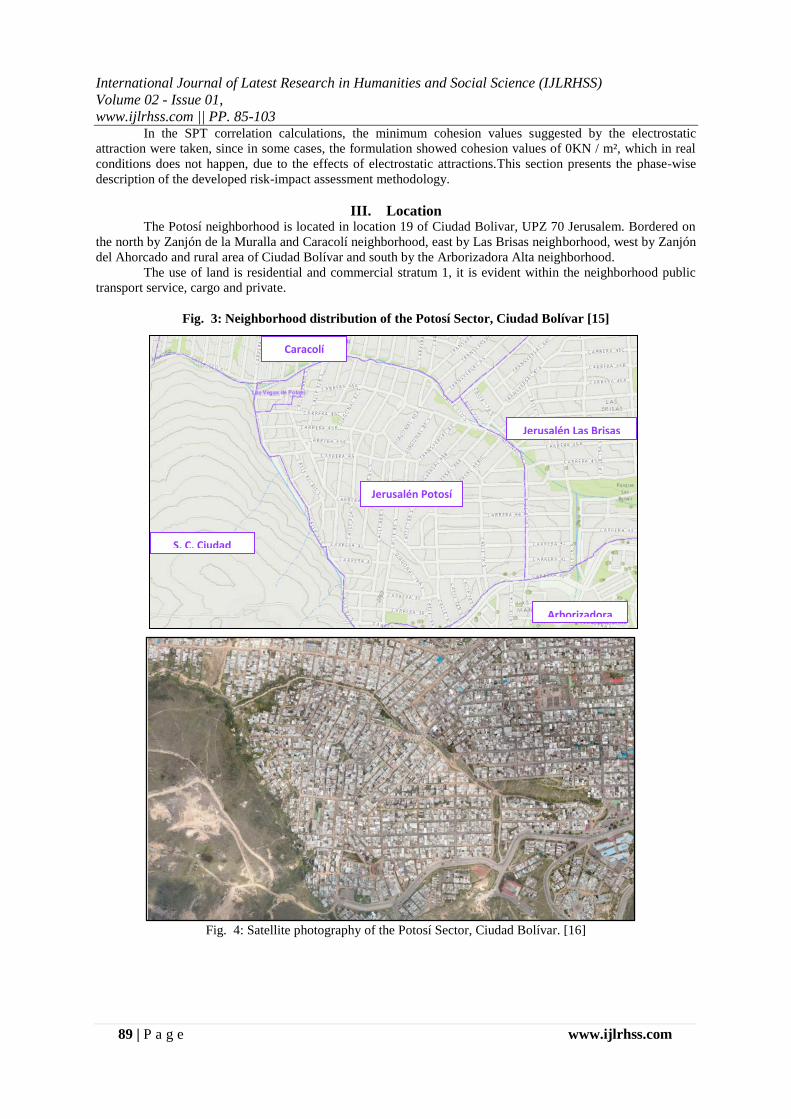
III. Location The Potosí neighborhood is located in location 19 of Ciudad Bolivar, UPZ 70 Jerusalem. Bordered on
the north by Zanjón de la Muralla and Caracolí neighborhood, east by Las Brisas neighborhood, west by Zanjón
del Ahorcado and rural area of Ciudad Bolívar and south by the Arborizadora Alta neighborhood.
The use of land is residential and commercial stratum 1, it is evident within the neighborhood public
transport service, cargo and private.
Fig. 3: Neighborhood distribution of the Potosí Sector, Ciudad Bolívar [15]
Fig. 4: Satellite photography of the Potosí Sector, Ciudad Bolívar. [16]
Jerusalén Potosí
S. C. Ciudad
Bolivar
Arborizadora
Alta
Jerusalén Las Brisas
Caracolí

IJLRET
International Journal of Latest Research in Humanities and Social Science (IJLRHSS)
Volume 02 - Issue 01,
www.ijlrhss.com || PP. 85-103
90 | P a g e www.ijlrhss.com
IV. Geology 4.1 Regional Geology
In the central zone of the Eastern mountain range is the Sabana de Bogotá, from which rocks sprout
from the superior Cretaceous to the Quaternary, which are evidence of sedimentation conditions. In the
formations La Frontera, Chipaque, Conejo and Simijaca are the oldest rocks; this sedimentation occurred in
marine environments with the deposit of approximately 1,200m of sequence. The sedimentation conditions
change from the Campanian and it is deposited in distal zones, the sedimentation continues with the Formation
of Plaeners in the Superior Campanian.
The sedimentation of fluvial origin in the Paleogene and the Neogene in the origin of the formations
Regadera, Cacho, Bogotá and part of Tilatá. The Miocene is a time of active tectonics, folding, faulting and
uplift of the Eastern mountain range that affected the formations before depositing and possibly formed the
basin of the current Sabana de Bogotá.
The area of the Sabana de Bogota is an area that has a great diversity of resources that allow the supply
for itself and some close areas, in minerals such as gravel, clays, sands and coal, depending on the development
of a plan proper ordering. There are areas with salt diapirism, generally located in the core of the anticlines, such
as those observed in Nemocón, Zipaquirá and possibly between the sector of Sesquilé and La Calera. [17]
4.2 Local Geology
Thanks to geological and soil studies, Ciudad Bolivar can be divided into eleven zones, from which the
following stand out: One located to the north, corresponding to a relatively flat sector, with slight inclinations
surrounded by the neighborhoods of Candelaria la Nueva, San Francisco and Abraham Lincoln. This corrected
area of the Tunjuelito river is composed of expansive clays, which make the land unstable, threatening the
current housing, the non-continuation of the urbanization process is warned.
Due to the fillings caused by the old exploitations of material in the sector, the area delimited by the
artillery school (Tunjuelito), the neighborhood Mexico to the north and, neighborhood the Cortijo to the south,
whose soils are mainly composed of sandy-silty gravels, the area is at risk due to the instability of the land in the
attempt to urbanize. From the neighborhood Rincón and in a south to north way, passing by the areas of the
Volador, the Canteras of Peña Colorada and the Tanque, located in an intermediate point of CiudadBolívar
(Sierra Morena) sloping soils vary from 20 ° at 40 ° formed by sandy layers classified as high risk soils.
Towards the west of neighborhood Los Alpes, the Colombian Institute of Geology and Mining INGEOMINAS
recommends urbanizing in sectors with smoother slopes (15 to 30 °).In the village of Quiba the land is made up
of hard sandstones, with gentle inclinations that do not exceed 20°; what does not allow the presence of
geotechnical risks, making the area suitable for urbanization. [17]
V. Visual Diagnosis of Roads A visual diagnosis of all the road sections evidenced in the sector was made. While walking, important
information for the analysis of the actual condition of the roads was collected, such information was related to
the type of pavement, the condition of the pavement and if it had coverage of public services.
From this diagnosis a book was generated and given to the community. The document includes an
elaborate data sheet (see Fig. 3) that contains the technical data collected from each of the road sections. A total
of two hundred and eighteen (218) cards were made with the data of each section found in the sector. Also, for
the sections of paved roads, a diagnosis of pathologies present in the pavement was made, both for rigid and
flexible pavement, taking as reference the guidelines of the Visual Inspection of Flexible Floors manual [18] and
the INVIAS Visual Inspection of Rigid Pavement [19]. (Although some sections of the roads were paved, they
were not necessarily in good condition). From the diagnosis was generated a plan that contains the information
of the type of pavement of each section of the roads of the entire area that includes the neighborhoods of Potosí,
Las Brisas and Jerusalem in Ciudad Bolívar.
It was also made a parallel between the information generated, and that one provided by the IDU on its
web site. When comparing the diagnosis that was made with the information provided by the digital platforms,
numerous inconsistencies were evidenced, since in the diagnosis that was made, unpaved roads were found, but
in the IDU report they appear paved or finished.
Information from the different public services providers was collected and it was found that the
neighborhood has a full coverage of essential public services. (Drinking water and sewage system, energy and
natural gas). The study carried out in this diagnosis allowed to find the critical points where it was considered
necessary to have technical studies for slope stability. Although there are several interventions to be made, six
(6) critical points were prioritized.

IJLRET
International Journal of Latest Research in Humanities and Social Science (IJLRHSS)
Volume 02 - Issue 01,
www.ijlrhss.com || PP. 85-103
91 | P a g e www.ijlrhss.com
Fig. 1: Example sheet of the Visual Diagnosis of Roads.Source: Own creation
5.1 Charts and percentages of the diagnosis.
From the study carried out it can be established that more than 50% of the roads do not have a
pavement structure (affirmed or mill). This represents a potential risk for the inhabitants of the sector
considering that due to the difficult topographic conditions, the displacement is very difficult for anyone, but it
is even more difficult for people with disabilities, elderly people, pregnant women and children. The
displacement of people would be even more dangerous depending on how optimal are the weather conditions.
The results of the study carried out are the following:
Table 2: Total sections according to types of pavements.Source: Own creation.
Road Section Mesh Type
V9 Local
0 1 2 X
Tab for data collection 101
Visual diagnosis of roads and slope stability design in the Potosí sector – Ciudad Bolívar
LOCATION
PHOTOGRAPHIC RECORD
PRESENTS SEWERAGE
PRESENTS ROCK BODIES
TYPE OF PAVEMENT
PRESENTS DAMAGE TO THE PAVEMENT
6.6 5.8
TRACK SECTION CIV
19005077 CL 77 SOUTH BETWEEN KR 44B Y KR 45
36.6
YES
DO NOT
AFFIRMED
YES
DO NOT
(Measurement scale from 0 to 2, where 0 does not require intervention and 2 requires immediate intervention)
No platform on either side
Requires construction of road mesh and walk
Unpaved road
PRESENTS OR IS IN STUDY AND DESIGN THE ROAD
OBSERVATIONS
CHARACTERISTICS OF THE ROAD SECTION
DIMENSIONS OF THE ROAD SECTIONROAD AXIS (m) INITIAL WIDTH (m) FINAL WIDTH (m)
REQUIRED INTERVENTION
PAVEMENTS SECTIONS
AFFIRMED 112
FLEXIBLE 24
MILLING 52
RIGID 29
STONE 1
TOTAL 218

IJLRET
International Journal of Latest Research in Humanities and Social Science (IJLRHSS)
Volume 02 - Issue 01,
www.ijlrhss.com || PP. 85-103
92 | P a g e www.ijlrhss.com
Fig. 2 : Total percentage of sections according to types of pavements.Source: Own creation.
Chart 1: Total meters according to types of pavements. Source: Own creation
Fig. 3 : Total meters according to types of pavements.Source: Own creation
.
Fig. 4: Total percentage according to length obtained from the different types of pavements Source: Own
creation.
AFFIRMED51.38%
FLEXIBLE11.01%
MILLING23.85%
RIGID13.30%
STONE0.46%
AFFIRMED
FLEXIBLE
MILLING
RIGID
STONE
PAVEMENTS SECTIONS
AFFIRMED 5246.15
FLEXIBLE 1516.84
MILLING 3072.26
RIGID 1492.5
STONE 97.49
TOTAL 11425.24
5,246.15
1,516.84
3,082.26
1,492.50
97.49
0
1000
2000
3000
4000
5000
6000
AFFIRMED FLEXIBLE MILLING RIGID STONE
45.88%
13.26%
26.95%
13.05%
0.85%
AFFIRMED
FLEXIBLE
MILLING
RIGID
STONE

IJLRET
International Journal of Latest Research in Humanities and Social Science (IJLRHSS)
Volume 02 - Issue 01,
www.ijlrhss.com || PP. 85-103
93 | P a g e www.ijlrhss.com
VI. Topography The topography was performed with Topcon Total Station GTS 120N, where more than one thousand
(1000) points were taken in the places where a slope stability study was required, the georeferencing was done
with an Ashtech Promark GPS Antenna (see attached report). A total of 6 sections were analyzed as it is shown
below.
Slope 1 – KR 44 between CL 76 SUR and CL 78 SUR
Fig. 9: Slope 1 Source: Own creation.
Slope 2 – KR 43 between CL 77 SUR and CL 78 SUR
Fig. 10: Slope 2 Source: Own creation.
Slope 3 – CL 82C SUR between KR 45 and KR 45B
Fig. 11: Slope 3 Source: Own creation.

IJLRET
International Journal of Latest Research in Humanities and Social Science (IJLRHSS)
Volume 02 - Issue 01,
www.ijlrhss.com || PP. 85-103
94 | P a g e www.ijlrhss.com
Slope 4 – KR 46A between DG 82A SUR and CL 72B SUR
Fig. 12: Slope 4 Source: own creation
Slope 5 – CL 81 SUR between KR 38 and KR 39
Fig. 13: Slope 5 Source: own creation
Slope 6 – KR 40 between CL 77 SUR and CL 78 SUR
Fig. 14: Slope 6 Source: own creation
Topographic plans were made with their respective transversal cuts for each slope, the cross section is
taken at the critical point of the slope, that is, the point where the height and the slope are greater; This is due to

IJLRET
International Journal of Latest Research in Humanities and Social Science (IJLRHSS)
Volume 02 - Issue 01,
www.ijlrhss.com || PP. 85-103
95 | P a g e www.ijlrhss.com
the fact that it is at these points that it is necessary to carry out soil explorations and design models. A general
map of the location of the intervention points of the six (6) slopes is also generated.
VII. Exploration Y Labs 7.1 Exploration
For the in-situ soil explorations, SPT perforations were made, two (2) per slope: one in the top and the
other in the base of the slope. Considering that there were 6 slopes to be evaluated, twelve (12) explorations
were made in total. The penetration was until reaching the point of rejection (more than 50 strokes) or up to the
maximum height of each slope.
Fig. 15: Soil exploration in-situ. Source: own creation.
7.2 Labs
Fig. 16: Laboratory tests. Own source
The laboratory tests were carried out with the samples obtained from the SPT, where they were tested
for granulometry by sieving, natural humidity, limits of Atterberg, unit weight by paraffin and soil classification.
Direct cutting tests were not performed due to the fact that under ideal conditions, the samples have to be

IJLRET
International Journal of Latest Research in Humanities and Social Science (IJLRHSS)
Volume 02 - Issue 01,
www.ijlrhss.com || PP. 85-103
96 | P a g e www.ijlrhss.com
extracted from the soil, in an unaltered way, and the SPT (standard penetration test) extracts only undisturbed
samples.
The undisturbed samples are extracted with triaxial tests, but granular and rocky soils were found, such
samples would not fit in the test cylinder. This is why the calculation of friction angle and soil cohesion were
calculated with the SPT hits correlation procedure, designed by Engineer Álvaro J. González García, professor
at National University.
VIII. Analysis of Stability In total, six (6) slopes were studied, however, only the analysis, results and designs of only one (1)
slope would be shown, this, considering that the process was the same for all the slopes. It is important to
mention that Slope 1 does not require containment structure, this is because the slope by itself meets the safety
factor in both the static and the dynamic case according to NSR - 10, title H. And for the slope 5, no intervention
was developed, since rocky bodies were evident in the whole surface of the slope, the analysis in rocks is
different from the analysis of the soil. To obtain their physical-mechanical properties, it was necessary the RQD
(Rock Quality Designatión) test that is developed by geologists with different equipment that it was not possible
to have for the exploration, compared to the SPT equipment that was used for the other explorations and which
was completely available.
Table 4: Stratigraphic profile - Slope 2 Source: Own creation.
Fig. 17: Stratigraphic profile - Slope 2. Source: own creation
8.1 Static Case
According to the NSR-10 standard, the minimum safety factor for slope stability is 1.5. The selected
slopes are modeled below, in case that the slope has a safety factor less than 1.5, it is necessary to carry out a
stabilization design for that slope. All the analysis models were developed by the software Slide 6.0 which is
ideal for the analysis of slope stability and, all the data, with which the analyzes were fed, were obtained in the
calculations of the laboratory tests and the correlations of the SPT test.The analyzes were developed with
overloads of 50kN / m² that simulate the efforts on the top of the slope, which the ground would have to support
for vehicular traffic and machinery.
Layer
CP
1
2
3
Stratigraphic profile Slope 2
Material
Poorly graded sand with the presence of silt
Sand poorly graded coffee with traces of rust
Poorly graded orange sand
Poorly graded sand with low plasticity slime

IJLRET
International Journal of Latest Research in Humanities and Social Science (IJLRHSS)
Volume 02 - Issue 01,
www.ijlrhss.com || PP. 85-103
97 | P a g e www.ijlrhss.com
Slope 2
Fig. 18: Static Analysis – Slope 2. Source: own creation
FS=1.407 DOES NOT MEET, requires stabilization design.
8.2 Dynamic Case
For the dynamic case, what must be taken into consideration is the possible effects of an earthquake on
the structure. For this case as for the static case, the standard sets a minimum-security factor for the slope,
however, and unlike the static case, this Security Factor is 1.05. All the models of analysis were developed using
the software Slide 6.0, ideal for the analysis of slope stability. All the data that contributed to the analyzes were
obtained in the calculations of the laboratory tests and the correlations of the SPT test. However, for the
dynamic case, it has to be considered the factor of spectral acceleration (acceleration that is necessary to load the
model). This factor was obtained from the seismic microzoning of Bogotá (for this specific case) from where a
coefficient of horizontal seismic force of 0.16 was obtained and a vertical one of 0.016. This applies only to
Zone 5 (see Bogota seismic microzoning). The analyzes were carried out with overloads of 50kN / m² which
simulate the efforts in the top of the slope, which would have to support the ground for vehicular and machinery
traffic.
For zone 5:
Am=Aa
Am=0.2
Horizontal force =Aa*0.8=0.2*0.8=0.16
Vertical force=10% Horizontal force=0.1*0.16=0.016
Fig. 19: Minimal indirect security factors. [20]
DESIGN 1.05
< 1/4
BEARING CAPACITY
CONDITION BUILDING STATIC SISM STATIO SEUDO
GLIDE 1.6 1.6
INTRINSIC STABILITY POTTERY MATERIALS (reinforced or not)
INTRINSIC STABILITY MANUFACTURED MATERIALS
EXCENTRICITY IN THE SENSE OF THE MOMENT (e / B). < 1/6 < 1/6 DESIGN
1.5 DESIGN 1.05
Adjacent slopes (zone of influence> 2.5H) 1.2 1.5 DESIGN 1.05
EQUAL TO THOSE IN TABLE H.4.1
EQUAL TO THOSE IN TABLE H.2.1
ACCORDING TO MATERIAL (CONCRETE-TITLE C; WOOD-TITLE G; ETC.)
GENERAL STABILITY OF THE SYSTEM:
PERMANENT OR LONG-LASTING (> 6 months)
1.2 1.3 50% OF DESIGN 1TEMPORARY OR SHORT-TERM (<6 months)
> 3.00 > 3.00 DESIGN > 2.00
VOLCAMIENTO: THE ONE THAT RESULTS MORE CRITICISM OF
RESISTANT MOMENT / MOMENT ACTUATING EXCENTRICITY IN
THE SENSE OF THE MOMENT (e / B).
1.2
IJLRET
International Journal of Latest Research in Humanities and Social Science (IJLRHSS)
Volume 02 - Issue 01,
www.ijlrhss.com || PP. 85-103
98 | P a g e www.ijlrhss.com
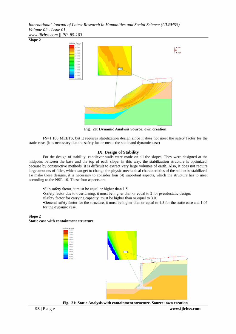
Slope 2
Fig. 20: Dynamic Analysis Source: own creation
FS=1.180 MEETS, but it requires stabilization design since it does not meet the safety factor for the
static case. (It is necessary that the safety factor meets the static and dynamic case)
IX. Design of Stability For the design of stability, cantilever walls were made on all the slopes. They were designed at the
midpoint between the base and the top of each slope, in this way, the stabilization structure is optimized,
because by constructive methods, it is difficult to extract very large volumes of earth. Also, it does not require
large amounts of filler, which can get to change the physic-mechanical characteristics of the soil to be stabilized.
To make these designs, it is necessary to consider four (4) important aspects, which the structure has to meet
according to the NSR-10. These four aspects are:
•Slip safety factor, it must be equal or higher than 1.5
•Safety factor due to overturning, it must be higher than or equal to 2 for pseudostatic design.
•Safety factor for carrying capacity, must be higher than or equal to 3.0.
•General safety factor for the structure, it must be higher than or equal to 1.5 for the static case and 1.05
for the dynamic case.
Slope 2
Static case with containment structure
Fig. 21: Static Analysis with containment structure. Source: own creation

IJLRET
International Journal of Latest Research in Humanities and Social Science (IJLRHSS)
Volume 02 - Issue 01,
www.ijlrhss.com || PP. 85-103
99 | P a g e www.ijlrhss.com
FS=1.531 MEETS
Dynamic case with containment structure
Fig. 5: Dynamic Analysis with containment structure. Source: own creation
FS=1.395 MEETS
Calculation Table2: Calculations of safety factors of the structure. Source:own creation
γ 1 17.49 kN/m³ α 6.00 °
φ' 1 34.81 ° γ concreto 23.50 kN/m³
c' 1 0.00 kN/m² γ peso ideal 18.00 kN/m³
H' 4.940 m
K a 0.277
P a 59.115 kN/m P h 58.791 kN/m
P v 6.179 kN/m ƩM o 96.810 kN(m/m)
1 1.72 40.42 0.80 32.34
2 0.48 11.28 0.63 7.11
3 1.40 32.90 1.40 46.06
4 7.31 131.58 2.40 315.79
5 0.12 2.16 2.13 4.60
Pv 6.18 6.18 38.19
ΣV 224.52 ΣM R 444.08
γ 2 17.77 kN/m³ c' 2 0.99 kN/m²
φ' 2 37.00 ° D 1.00 m
K P 4.02
Pp 39.71 kN/m
B 2.80 m φ' 2 37.00 °
N c 55.63 N y 66.19N q 42.92
e -0.147 B/6 0.47
q max 54.97 F yd 1.00
q 17.77 ψ° 14.67
B' 3.09 F ci 0.70
F qd 1.08 F γ i 0.00
F cd 1.08 q u 617.16
Slope 2 Design Containment Structure
OVERTURNINGINITIAL DATA
CALCULATIONS
RESISTANT MOMENT
SECTIONAREA
(m²)
WEIGHT /
STRENGTH
ARM
(m)
MOMENT
(kN(m/m))
FS ( OVERTURNING) 4.5872 MEET
GLIDEINITIAL DATA
CALCULATIONS
FS (GLIDE) 2.4742 MEET
CARRYING CAPACITYINITIAL DATA
PARAMETERS ACCORDING TO THE MEYERHOF TABLE
CALCULATIONS
e < B/6
FS (BEARING CAPACITY) 11.2269 MEET
− −
−
𝐹
𝐹 𝑉 𝑎
𝐹
IJLRET
International Journal of Latest Research in Humanities and Social Science (IJLRHSS)
Volume 02 - Issue 01,
www.ijlrhss.com || PP. 85-103
100 | P a g e www.ijlrhss.com
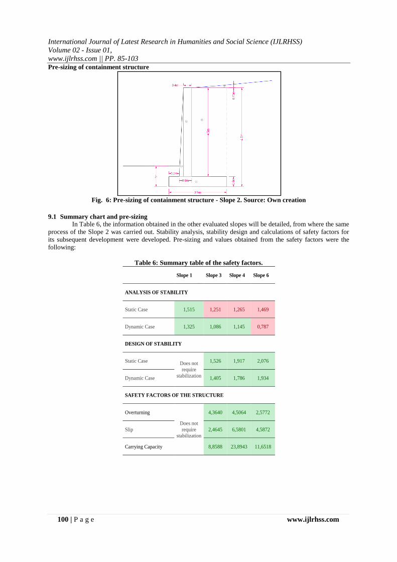
Pre-sizing of containment structure
Fig. 6: Pre-sizing of containment structure - Slope 2. Source: Own creation
9.1 Summary chart and pre-sizing
In Table 6, the information obtained in the other evaluated slopes will be detailed, from where the same
process of the Slope 2 was carried out. Stability analysis, stability design and calculations of safety factors for
its subsequent development were developed. Pre-sizing and values obtained from the safety factors were the
following:
Table 6: Summary table of the safety factors.
Slope 1 Slope 3 Slope 4 Slope 6
ANALYSIS OF STABILITY
Static Case 1,515 1,251 1,265 1,469
Dynamic Case 1,325 1,086 1,145 0,787
DESIGN OF STABILITY
Static Case Does not
require
stabilization
1,526 1,917 2,076
Dynamic Case 1,405 1,786 1,934
SAFETY FACTORS OF THE STRUCTURE
Overturning
Does not
require
stabilization
4,3640 4,5064 2,5772
Slip 2,4645 6,5801 4,5872
Carrying Capacity 8,8588 23,8943 11,6518

IJLRET
International Journal of Latest Research in Humanities and Social Science (IJLRHSS)
Volume 02 - Issue 01,
www.ijlrhss.com || PP. 85-103
101 | P a g e www.ijlrhss.com
Pre-sizing of containment structure
Fig. 7: Pre-sizing of containment structure - Slope 3. Source: Own creation
Fig. 8: Pre-sizing of containment structure - Slope 4. Source: Own creation
Fig. 9: Pre-sizing of containment structure - Slope 6. Source: Own creation

IJLRET
International Journal of Latest Research in Humanities and Social Science (IJLRHSS)
Volume 02 - Issue 01,
www.ijlrhss.com || PP. 85-103
102 | P a g e www.ijlrhss.com
X. Conclusions This diagnosis contains information collected during the second half of 2016, for this reason, at the
moment of reading this paper it is probably that the condition of the roads and information centers may be
subject of changes, repairs or even deterioration. From this study it can be established that more than 50% of
the roads do not have a pavement structure (affirmed or mill). This represents a potential risk for the inhabitants
of the sector considering that due to the difficult topographic conditions, the displacement is very difficult for
anyone, but it is even more difficult for people with disabilities, elderly people, pregnant women and children.
The displacement of people would be even more dangerous depending on how optimal are the weather
conditions.
It is important to note that even if a track of the road is paved, it is not necessarily in a good condition.
For this reason, it was also carried out a visual diagnosis of the pathologies of the flexible and rigid pavement,
which were obtained from the visual diagnosis of pathways. From this study we can say that there are some
roads in which, due to the time and the use, it starts to be difficult to go by in both vehicle and walking.
The topography carried out allowed us to find the neuralgic points where it was necessary to have penetration of
soils (always looking for the place where the slope had greater height); and the georeferencing locates the
planimetry in the real space where it is necessary to work.
Through tests carried out in the laboratories of CorporaciónUniversitaria Minuto de Dios, it is
reaffirmed that the soil of Potosí can be classified as colluvium, since it is a deposit of soils by mass movements
and presents fine and granular mixed material. This represents a stable soil, however, considering the
appearance of building constructions, continuous deposits of rubble in the whole sector and cuts of slopes
without considering natural rest angles, the soil loses a considerable consistency.
With the calculations obtained through the in-situ SPT test and the software models, it was possible to
corroborate that the slopes are able to support their own weight (reason why there are no landslides). However,
when evaluating it with normal overloads such as vehicular traffic, dynamic effects such as seismic movement
or housing a dead load, most of the slopes in these situations would collapse.
It is evident that the slopes that were studied in the neighborhood of Jerusalem in the area of Potosí of
Ciudad Bolivar, a large part, require a slope stability design (the design suggested and developed in this
document, is done through cantilevered retaining walls). Due to unstable soils, the current condition of the roads
represents a risk for the community, if it is not stabilized first it is impossible to build pavement structures.
However, from this study it is known that the Slope 1 is stable by itself and even in the middle of overloads or
dynamic effects, it does not require stabilization structure
The slopes mentioned here, do not necessarily refer to all the points where it is necessary to stabilize,
they are only part of some of the routes that were prioritized, however, there were more points where it is
necessary to study slope stability as well. For future studies it is recommended to carry out tests for rocks,
requiring a trained geologist to obtain the physical-mechanical characteristics of rocky soils through different
methods. This, considering that in some points of the rout we took, the soil was made up of rock, and at that
time we did not have access to equipment needed to develop such trials.
Two (2) documents were given to the community, they can be used for both consultation and technical
support, when the community desires to request to the corresponding entities the construction, maintenance or
rehabilitation of the roads. The first document is addressed to the General Diagnosis of Roads, and the second
one refers to the slope stability designs.
XI. References [1]. [1] INVIAS, «I. N. V. E-102 Descripción e identificación de suelos (Procedimiento manual y visual) »
INVIAS, Bogotá D. C., 2012.
[2]. [2] INVIAS, «I. N. V. E-111 Ensayo normal de penetración (SPT) y muestreo de suelos con
tubopartido» INVIAS, Bogotá D. C., 2012.
[3]. [3] INVIAS, «I. N. V. E-122 Determinaciónenlaboratorio del contenido de agua (humedad) de muestra
de suelo, roca y mezclas de suelo-agregado» INVIAS, Bogotá D. C., 2012.
[4]. [4] INVIAS, «I. N. V. E-123 Determinación de los tamaños de partículas de los suelos» INVIAS,
Bogotá D. C., 2012.
[5]. [5] INVIAS, «I. N. V. E-125 Determinación del límitelíquido de los suelos» INVIAS, Bogotá D. C.,
2012.
[6]. [6] INVIAS, «I. N. V. E-126 Límiteplástico e índice de plasticidad de los suelos» INVIAS, Bogotá D.
C., 2012.
[7]. [7] W. A. Botía Diaz, «MANUAL DE PROCEDIMIENTOS DE ENSAYOS DE SUELOS Y
MEMORIA DE CÁLCULO» UNIVERSIDAD MILITAR NUEVA GRANADA, Bogotá D. C., 2015.

IJLRET
International Journal of Latest Research in Humanities and Social Science (IJLRHSS)
Volume 02 - Issue 01,
www.ijlrhss.com || PP. 85-103
103 | P a g e www.ijlrhss.com
[8]. [8] Á. J. González García, «CALCULO SIMPLIFICADO DE CAPACIDAD PORTANTE DE
CIMIENTOS SUPERFICIALES EN LADERA» de ESCUELA COLOMBIANA DE INGENIERIA -
III ENCUENTRO DE INGENIEROS DE SUELOS Y ESTRUCTURAS, Bogotá D. C., 2015.
[9]. [9] Servicios de Ingeniería y Construcción LTDA - SERVINC, Manual de Diseño de
CimentacionesSuperficiales y Profundas para Carreteras, Bogotá D. C.: INVIAS, 2012.
[10]. [10] AASHTO, Standard Specification for highway bridges, Washington D. C.: AASHTO, 1996.
[11]. [11] Federal Highway Administration FHWA, Soils and Foundations, Washington D. C.: National
Highway Institute, 2006.
[12]. [12] B. M. Das, «Fundamentos de IngenieríaGeotécnica» de Fundamentos de IngenieríaGeotécnica,
México D. F., Cenage Learning, 2015, p. 418.
[13]. [13] D. M. Arguello Romero y L. A. Calderón Goyeneche, «ESTADO DEL ARTE DEL USO DEL
ENSAYO SPT-T Y LAS CORRELACIONES OBTENIDAS PARA LOS PARÁMETROS DEL
MODELO MOHR-COULOMB» Universidad Católica de Colombia, Bogotá, 2014.
[14]. [14] J. K. Mitchell y K. Soga, «Fundamentals of Soil Behavior, » de Fundamentals of Soil Behavior,
New Jersey, Wiley, 2005, p. 174.
[15]. [15] IDECA La IDE de Bogotá D.C, «INSTITUTO DE DESARROLLO URBANO
InventarioInfraestructuraVial,» 6 Mayo 2017. [Enlínea]. Available:
http://gisidu.idu.gov.co/portalgis/apps/webappviewer/index.html?id=9b59c275409b466a890b7b8eebfc
79cf.
[16]. [16] IDECA La IDE de Bogotá D.C, «MapasBogotá,» 16 Mayo 2017. [Enlínea]. Available:
http://mapas.bogota.gov.co/.
[17]. [17] D. M. Montoya Arenas y G. A. Reyes Torres, «GEOLOGÍA DE LA SABANA DE BOGOTÁ»
INSTITUTO COLOMBIANO DE GEOLOGÍA Y MINERÍA, Bogotá, 2005.
[18]. [18] Grupo Técnico - Convenio 587 de 2003, Manual para la inspección visual de pavimentos flexibles,
Bogotá: Universidad Nacional de Colombia, 2006.
[19]. [19] Grupo Técnico - Convenio 587 de 2003, Manual para la inspección visual de pavimentosrígido,
Bogotá: Universidad Nacional de Colombia, 2006.
[20]. [20] ASOCIACIÓN COLOMBIANA DE INGENIERÍA SÍSMICA., «NormasColombianas de. Diseño
y ConstrucciónSismo-Resistente, NSR-10 TituloH,» AIS, Bogotá, 2010.