virtuoso ams designer - picture.iczhiku.com
TRANSCRIPT

Version 5.4
Lecture Manual March 13, 2005
Virtuoso® AMS Designer

1990-2005 Cadence Design Systems, Inc. All rights reserved.Printed in the United States of America.
Cadence Design Systems, Inc., 555 River Oaks Parkway, San Jose, CA 95134, USA
Other Trademarks
Open SystemC, Open SystemC Initiative, OSCI, SystemC, and SystemC Initiative are trademarks or registered trademarks of Open SystemC Initiative, Inc. inthe United States and other countries and are used with permission.
All other trademarks are the property of their respective holders.
1st Silicon Success®Allegro®Assura™BuildGates®Cadence® (brand and logo)CeltIC™ClockStorm®CoBALT™Conformal®Connections®Design Foundry®Diva®Dracula®Encounter™Fire & Ice®First Encounter®
Cadence Trademarks
FormalCheck®HDL-ICE®Incisive™IP Gallery™Nano Encounter™NanoRoute™NC-Verilog®OpenBook® online documentation libraryOrcad®Orcad Capture®Orcad Layout®PacifIC™Palladium™Pearl®PowerSuite™PSpice®
QPlace®Quest®SeismIC™SignalStorm®Silicon Design Chain™Silicon Ensemble®SoC Encounter™SourceLink® online customer supportSpectre®TtME®UltraSim®Verifault-XL®Verilog®Virtuoso®VoltageStorm®
Trademarks and service marks of Cadence Design Systems, Inc. (Cadence) contained in this document are attributed to Cadence with the appropriate symbol.For queries regarding Cadence’s trademarks, contact the corporate legal department at the address above or call 800.862.4522.
Confidentiality Notice
No part of this publication may be reproduced in whole or in part by any means (including photocopying or storage in an information storage/retrieval system)or transmitted in any form or by any means without prior written permission from Cadence Design Systems, Inc. (Cadence).
Information in this document is subject to change without notice and does not represent a commitment on the part of Cadence. The information contained hereinis the proprietary and confidential information of Cadence or its licensors, and is supplied subject to, and may be used only by Cadence’s customer inaccordance with, a written agreement between Cadence and its customer. Except as may be explicitly set forth in such agreement, Cadence does not make, andexpressly disclaims, any representations or warranties as to the completeness, accuracy or usefulness of the information contained in this document. Cadencedoes not warrant that use of such information will not infringe any third party rights, nor does Cadence assume any liability for damages or costs of any kindthat may result from use of such information.
RESTRICTED RIGHTS LEGEND Use, duplication, or disclosure by the Government is subject to restrictions as set forth in subparagraph (c)(1)(ii) of theRights in Technical Data and Computer Software clause at DFARS 252.227-7013.
UNPUBLISHED This document contains unpublished confidential information and is not to be disclosed or used except as authorized by written contract withCadence. Rights reserved under the copyright laws of the United States.

Table of Contents Virtuoso AMS Designer
Table of Contents
Virtuoso AMS Designer
Module 1 Getting Started
Topics in this Module ...................................................................................................... 1-3Course Objectives ............................................................................................................ 1-5Day 1 Course Schedule.................................................................................................... 1-7Day 2 Course Schedule.................................................................................................... 1-9Day 3 Course Schedule.................................................................................................. 1-11Day 4 Course Schedule.................................................................................................. 1-13Virtuoso AMS Designer in the A/MS Course Flow ...................................................... 1-15Getting Help—CDSDoc ................................................................................................ 1-17Getting Help—Help Menus ........................................................................................... 1-19Getting Help—SourceLink ............................................................................................ 1-21Review ........................................................................................................................... 1-23Lab ................................................................................................................................. 1-25
Lab 1-1 Getting Started............................................................................................ 1-25
Module 2 Introduction to Virtuoso AMS Designer
Topics in this Module ...................................................................................................... 2-3What Is Virtuoso AMS Designer? ................................................................................... 2-5The Virtuoso AMS Designer Solution............................................................................. 2-9Virtuoso AMS Simulator Modes of Operation.............................................................. 2-11What Files Are Required?.............................................................................................. 2-13lib.cell:view Library Structure ....................................................................................... 2-15Using the Virtuoso AMS Environment.......................................................................... 2-17Virtuoso AMS Environment Simulation Flow .............................................................. 2-19The Hierarchy Editor ..................................................................................................... 2-21Binding Cells to Views .................................................................................................. 2-23Binding Netlist Text Files to Cells in the HE ................................................................ 2-25Binding Behavioral Verilog/A/AMS to Cells in the HE ............................................... 2-27Compiling Verilog/A/AMS Libraries ............................................................................ 2-29Cell Binding Tree View................................................................................................. 2-31Occurrence Binding ....................................................................................................... 2-33Saving Cell Bindings and Configurations ..................................................................... 2-35Configurations................................................................................................................ 2-37Run Directories .............................................................................................................. 2-39Run Directory Creation Options .................................................................................... 2-41
March 13, 2005 Cadence Design Systems, Inc. iii

Virtuoso AMS Designer Table of Contents
Setting the Simulation Stop Time.................................................................................. 2-43Setting the hdl.var Location........................................................................................... 2-45Design Prep.................................................................................................................... 2-47Selecting Signals for Saving and Plotting...................................................................... 2-49Run Simulation Form..................................................................................................... 2-51The SimVision Console and Design Browser ............................................................... 2-53SimVision Tool Selection Buttons ................................................................................ 2-55SimVision Simulation Control Buttons ......................................................................... 2-57The SimVision Waveform Viewer ................................................................................ 2-59SimVision Sidebar Panels.............................................................................................. 2-61Trace Signals Panel........................................................................................................ 2-63SimVision Signal Formatting ........................................................................................ 2-65Mid-Point Review.......................................................................................................... 2-67Lab ................................................................................................................................. 2-69
Lab 2-1 Introduction to Virtuoso AMS Designer .................................................... 2-69Schematic Netlists.......................................................................................................... 2-71Spectre vs. Verilog-AMS Netlists.................................................................................. 2-73cds_globals Module ....................................................................................................... 2-75The SimVision Source Browser..................................................................................... 2-77Creating Signal Probes in SimVision ............................................................................ 2-79Setting Breakpoints........................................................................................................ 2-81Showing Breakpoints ..................................................................................................... 2-83SimVision Schematic Tracer ......................................................................................... 2-85SimVision Register Window ......................................................................................... 2-87SimVision Remote Connections .................................................................................... 2-89Lab ................................................................................................................................. 2-91
Lab 2-2 Replacing a Behavioral Model with a Transistor-Level Schematic........... 2-91
Module 3 Command-Line Control of Virtuoso AMS Designer
Topics in this Module ...................................................................................................... 3-3Virtuoso AMS Designer Tool Flow................................................................................. 3-5AMS Control Files........................................................................................................... 3-7The cds.lib File................................................................................................................. 3-9The hdl.var File.............................................................................................................. 3-11The Simulation Control File .......................................................................................... 3-13Command-Line Simulation Flow .................................................................................. 3-15Command-Line Options: ncvlog.................................................................................... 3-17Command-Line Options: ncvhdl.................................................................................... 3-19Command-Line Options: ncelab.................................................................................... 3-21Command-Line Options: ncsim ..................................................................................... 3-23
iv Cadence Design Systems, Inc. March 13, 2005

Table of Contents Virtuoso AMS Designer
NC Profiler..................................................................................................................... 3-25NCVerilog...................................................................................................................... 3-27UNIX Scripts for Running AMS ................................................................................... 3-29Command-Line Design Prep.......................................................................................... 3-31Schematic Netlists.......................................................................................................... 3-33Custom Netlisting .......................................................................................................... 3-35The .pak File .................................................................................................................. 3-37.pak File Contents .......................................................................................................... 3-39Tcl Commands ............................................................................................................... 3-41TCL Current Probes....................................................................................................... 3-43Tcl Scripts ...................................................................................................................... 3-45Simulation Save/Restart................................................................................................. 3-47Applications for Save/Restart ........................................................................................ 3-49Save/Restart Usage ........................................................................................................ 3-51Use S/R to Change Spectre Controls or Digital Values................................................. 3-53A Sample S/R Session ................................................................................................... 3-55Review ........................................................................................................................... 3-57Labs................................................................................................................................ 3-59
Lab 3-1 Command-Line Control of Virtuoso AMS Designer ................................. 3-59Lab 3-2 Working with Configurations from the Command Line ............................ 3-59Lab 3-3 Mixing VHDL and Verilog (Optional) ...................................................... 3-59
Module 4 Virtuoso AMS Designer in ADE
Topics in this Module ...................................................................................................... 4-3AMS in ADE.................................................................................................................... 4-5Files Required for AMS in ADE ..................................................................................... 4-7Starting AMS in ADE...................................................................................................... 4-9Setting Up AMS in ADE ............................................................................................... 4-11Choosing Connect Rules................................................................................................ 4-13Setting Up the Simulation in AMS in ADE................................................................... 4-15Transient Simulation Options ........................................................................................ 4-17AMS in ADE DC Simulation ........................................................................................ 4-19AC Simulation Options.................................................................................................. 4-21WaveScan Waveform Display....................................................................................... 4-23Labs................................................................................................................................ 4-25
Lab 4-1 Using AMS in ADE ................................................................................... 4-25Lab 4-2 AC Analysis with AMS in ADE ................................................................ 4-25Lab 4-3 Parasitic Simulation in AMS...................................................................... 4-25Lab 4-4 Running the SAR A2D in ADE (Optional)................................................ 4-25
March 13, 2005 Cadence Design Systems, Inc. v

Virtuoso AMS Designer Table of Contents
Module 5 Virtuoso AMS Designer in VSDE
Topics in this Module ...................................................................................................... 5-3AMS in VSDE ................................................................................................................. 5-5Setting Up a VSDE AMS Project .................................................................................... 5-7Creating Test Measures.................................................................................................... 5-9Defining the Corners to Be Simulated ........................................................................... 5-11Viewing Results ............................................................................................................. 5-13Compare Results in a Waveform Display...................................................................... 5-15Labs................................................................................................................................ 5-17
Lab 5-1 Using AMS in VSDE ................................................................................. 5-17
Module 6 Analog Solver, Spectre, and SPICE
Topics in this Module ...................................................................................................... 6-3Analog Solver .................................................................................................................. 6-5Refresher on Simulation Control Files ............................................................................ 6-7AMS Instantiation of Primitives ...................................................................................... 6-9Bsource Support............................................................................................................. 6-11Declaring Model Files with Sections............................................................................. 6-13Declaring Models and Subcircuits in the hdl.var File ................................................... 6-15Instantiating SPICE/Spectre Models.............................................................................. 6-17Analog Model Form....................................................................................................... 6-19MOS Table Model ......................................................................................................... 6-21Verilog-A Table Models ................................................................................................ 6-23Instantiating SPICE/Spectre Subcircuits........................................................................ 6-25Using Globals in a Subcircuit ........................................................................................ 6-27Spectre Netlists .............................................................................................................. 6-29Spectre Encryption......................................................................................................... 6-31Review ........................................................................................................................... 6-33Labs................................................................................................................................ 6-35
Lab 6-1 Instantiating SPICE/Spectre Models in a Configured Schematic .............. 6-35Lab 6-2 Instantiating SPICE/Spectre Subcircuits from the Command Line ........... 6-35Lab 6-3 Using Global Signals in Subcircuits (Optional) ......................................... 6-35Lab 6-4 Exploring Spectre Table Models (Optional) .............................................. 6-35
Module 7 Introduction to the Verilog-AMS Language
Topics in this Module ...................................................................................................... 7-3Verilog-AMS History ...................................................................................................... 7-5Verilog-AMS Features..................................................................................................... 7-7Cadence Extensions to Verilog-AMS.............................................................................. 7-9
vi Cadence Design Systems, Inc. March 13, 2005

Table of Contents Virtuoso AMS Designer
Verilog-D Changes from AMS...................................................................................... 7-11Verilog-A Changes from AMS...................................................................................... 7-13Verilog-D Modules ........................................................................................................ 7-15Behavioral Representation Using Verilog-D................................................................. 7-17Instantiating Verilog-D Modules ................................................................................... 7-19Verilog-A Modules ........................................................................................................ 7-21Instantiating Verilog-A Modules ................................................................................... 7-23Comparing Analog and Digital Modules....................................................................... 7-25The Contribution Operator............................................................................................. 7-27A Verilog-AMS Module ................................................................................................ 7-29Verilog-AMS Modules .................................................................................................. 7-31A Behavioral Verilog-AMS Module ............................................................................. 7-33A Structural AMS Module............................................................................................. 7-35Parameters and Ports...................................................................................................... 7-37Domains, Discipline, and Direction............................................................................... 7-39Connect Modules ........................................................................................................... 7-41The wreal Datatype........................................................................................................ 7-43An Example of wreal Usage .......................................................................................... 7-45A wreal A2D Converter in Verilog-AMS ..................................................................... 7-47IP Source Code Protection ............................................................................................. 7-49The ncprotect Utility...................................................................................................... 7-51Behavioral Mixed-Signal Model Library....................................................................... 7-53Review ........................................................................................................................... 7-55Labs................................................................................................................................ 7-57
Lab 7-1 Exploring Verilog-AMS Language and Connect Modules........................ 7-57Lab 7-2 Running the wreal A2D Converter (Optional) ........................................... 7-57
Module 8 Discipline Resolution
Topics in this Module ...................................................................................................... 8-3Simulation Domains ........................................................................................................ 8-5Disciplines........................................................................................................................ 8-7Connect Module Types .................................................................................................... 8-9Connect Rules ................................................................................................................ 8-11Merged vs. Split Connect Rules..................................................................................... 8-13Provided Connect Modules............................................................................................ 8-15Provided Connect Rules................................................................................................. 8-17Bi-Directional Connect Modules ................................................................................... 8-19Solving Rigid Branches ................................................................................................. 8-21Assigning Disciplines for Multiple Supplies ................................................................. 8-23Supply-Dependent Connect Modules ............................................................................ 8-25
March 13, 2005 Cadence Design Systems, Inc. vii

Virtuoso AMS Designer Table of Contents
Modifying the Connect Module for Supply Sensitivity................................................. 8-27Modifying the Digital Port for Supply Sensitivity......................................................... 8-29Making Connect Modules Sensitive to Inherited Connection Values ........................... 8-31Discipline Resolution..................................................................................................... 8-33Net Discipline Resolution .............................................................................................. 8-35Default Discipline Resolution........................................................................................ 8-37Default Automatic Insertion of CMs ............................................................................. 8-39Detailed Discipline Resolution ...................................................................................... 8-41Detailed Automatic Insertion of CMs............................................................................ 8-43Using an OOMR Discipline Declaration ....................................................................... 8-45Review ........................................................................................................................... 8-47Labs................................................................................................................................ 8-49
Lab 8-1 Exploring Discipline Resolution ................................................................ 8-49Lab 8-2 Bidirectional Connect Modules (Optional) ................................................ 8-49
Module 9 AMS Mixed-Signal Interaction
Topics in this Module ...................................................................................................... 9-3Basic Mixed-Signal Interaction in AMS.......................................................................... 9-5Analog Signals in Digital Expressions ............................................................................ 9-7Digital Signals in Analog Expressions ............................................................................ 9-9Analog Events in Digital Event Control ........................................................................ 9-11Cross and Above Functions ........................................................................................... 9-13Fast Cross Operator........................................................................................................ 9-15Digital Events in Analog Event Control ........................................................................ 9-17Shared Variables ............................................................................................................ 9-19Mixed-Signal Modules................................................................................................... 9-21Example 1—VCO.......................................................................................................... 9-23Example 2—Comparator ............................................................................................... 9-25Example 3—Frequency to Voltage Converter............................................................... 9-27Review ........................................................................................................................... 9-29Labs................................................................................................................................ 9-31
Lab 9-1 Mixed-Signal Interaction............................................................................ 9-31Lab 9-2 Writing an AMS VCO Module .................................................................. 9-31Lab 9-3 Mixed-Signal Sensitivities (Optional)........................................................ 9-31
Module 10 AMS Modeling Techniques
Topics in this Module .................................................................................................... 10-3Modeling for Speed........................................................................................................ 10-5Mixed Simulation Comparison ...................................................................................... 10-7
viii Cadence Design Systems, Inc. March 13, 2005

Table of Contents Virtuoso AMS Designer
Mixed-Signal Synchronization ...................................................................................... 10-9Analog Event Creation................................................................................................. 10-11Creating Analog Events ............................................................................................... 10-13Analog Events from Digital Events ............................................................................. 10-15Analog Time Steps From Analog Frequency .............................................................. 10-17Analog Events from Transition Statements ................................................................. 10-19Reading an Analog Value in a Digital Context ........................................................... 10-21Using Analog Events in a Digital Context................................................................... 10-23Review ......................................................................................................................... 10-25Labs.............................................................................................................................. 10-27
Lab 10-1 AMS Modeling Techniques ................................................................... 10-27
Module 11 VHDL-AMS Implementation
Topics in this Module .................................................................................................... 11-3The Need for VHDL-AMS ............................................................................................ 11-5Domains in VHDL-AMS............................................................................................... 11-7VHDL-AMS Mixed-Signal Domain.............................................................................. 11-9VHDL-AMS Extensions to VHDL (Digital)............................................................... 11-11VHDL-AMS Compared to Verilog-AMS ................................................................... 11-13VHDL-AMS Simulation Flow..................................................................................... 11-15Instantiating VHDL-AMS in Virtuoso AMS Designer ............................................... 11-17Cadence VHDL-AMS Summary ................................................................................. 11-19VHDL-AMS Current Implementation......................................................................... 11-21VHDL-AMS Supported Features ................................................................................ 11-23VHDL-AMS Currently Non-Supported Features........................................................ 11-25VHDL-AMS Environment Support Within DFII ........................................................ 11-27VHDL-AMS DFII Cell Views..................................................................................... 11-29VHDL-AMS Libraries ................................................................................................. 11-31VHDL-AMS Packages................................................................................................. 11-33VHDL-AMS Use Models ............................................................................................ 11-35VHDL-AMS Type I Designs ....................................................................................... 11-37VHDL-AMS Type II Designs...................................................................................... 11-39VHDL-AMS Type III Designs .................................................................................... 11-41Connect Module Insertion on Mixed Domains............................................................ 11-43Discipline—Nature Mapping....................................................................................... 11-45Quiz.............................................................................................................................. 11-47Lab ............................................................................................................................... 11-49
Lab 11-1 Type III Mixed-Signal, Mixed-Domain Connect Module Insertion ...... 11-49
March 13, 2005 Cadence Design Systems, Inc. ix

Virtuoso AMS Designer Table of Contents
Module 12 Introduction to the VHDL-AMS Language
Topics in this Module .................................................................................................... 12-3Origins of the VHDL-AMS Language .......................................................................... 12-5VHDL-AMS Designs..................................................................................................... 12-7VHDL vs. Verilog.......................................................................................................... 12-9VHDL-AMS Entity Declarations ................................................................................ 12-11VHDL-AMS Architecture Body.................................................................................. 12-13Description of Analog Behavior in VHDL-AMS........................................................ 12-15Basic Constructs in VHDL-AMS ................................................................................ 12-17Natures in VHDL-AMS............................................................................................... 12-19Defining Natures in VHDL-AMS................................................................................ 12-21VHDL-AMS Composite Nature Examples ................................................................. 12-23VHDL-AMS Non-Electrical Natures .......................................................................... 12-25VHDL-AMS Terminals ............................................................................................... 12-27VHDL-AMS Terminal Declarations............................................................................ 12-29VHDL-AMS Terminal Ports........................................................................................ 12-31VHDL-AMS Quantities ............................................................................................... 12-33VHDL-AMS Free Quantities....................................................................................... 12-35VHDL-AMS Quantity Ports ........................................................................................ 12-37VHDL-AMS Branch Quantities .................................................................................. 12-39VHDL Processes.......................................................................................................... 12-41Using the WAIT Statement.......................................................................................... 12-43VHDL-AMS Simple Simultaneous Statement ............................................................ 12-45Various Operators Using the Equal Sign ..................................................................... 12-47VHDL-AMS Solvability Checks ................................................................................. 12-49VHDL-AMS Simple Resistor Example....................................................................... 12-51VHDL-AMS Time Derivative Example...................................................................... 12-53VHDL-AMS Simple Inductor Example ...................................................................... 12-55Concurrent BREAK Statement .................................................................................... 12-57Concurrent BREAK Example...................................................................................... 12-59VHDL-AMS Initial Conditions Example .................................................................... 12-61VHDL-AMS Piecewise Defined Behavior.................................................................. 12-63VHDL-AMS Simultaneous IF/ELSE Statements........................................................ 12-65Attributes of VHDL-AMS Quantities.......................................................................... 12-67VHDL-AMS 'ABOVE Attribute Example—1 ............................................................ 12-69VHDL-AMS 'ABOVE Attribute Example—2 ............................................................ 12-71Quantity Attributes of Signals ..................................................................................... 12-73VHDL-AMS 'RAMP Attribute Example..................................................................... 12-75VHDL-AMS Inverter Architecture Example............................................................... 12-77VHDL-AMS VCO Architecture Example................................................................... 12-79
x Cadence Design Systems, Inc. March 13, 2005

Table of Contents Virtuoso AMS Designer
The NOW Function for Time Retrieval....................................................................... 12-81Labs.............................................................................................................................. 12-83
Lab 12-1 VHDL-AMS PWM Testbench............................................................... 12-83Lab 12-2 VHDL-AMS Switched Mode Power Supply ......................................... 12-83Lab 12-3 Writing a VHDL-AMS Inverter Module................................................ 12-83Lab 12-4 Writing a VHDL-AMS VCO (Optional)................................................ 12-83
Module 13 Migrating Designs to AMS
Topics in this Module .................................................................................................... 13-3Steps to Migrating a Mixed-Signal Design to AMS...................................................... 13-5Converting Analog Libraries to AMS............................................................................ 13-7Modifying SimInfo for AMS......................................................................................... 13-9SimInfo in CDF ........................................................................................................... 13-11Including Analog Model Files in AMS ....................................................................... 13-13Compile Digital Libraries ............................................................................................ 13-15Designing for Virtuoso AMS Designer Compliance—1............................................. 13-17Designing for Virtuoso AMS Designer Compliance—2............................................. 13-19Labs.............................................................................................................................. 13-21
Lab 13-1 Migrating a Peak Detector Design ......................................................... 13-21Lab 13-2 Mixed-Signal, Mixed-Language Simulation of a Complex PLL........... 13-21
Module 14 Virtuoso AMS Environment Reference (Optional)
Topics in this Module .................................................................................................... 14-3AMS Netlister Tool........................................................................................................ 14-5AMS Options ................................................................................................................. 14-7AMS Options—Check and Save ................................................................................... 14-9AMS Options from the Hierarchy Editor (HE)............................................................ 14-11AMS Options—Netlister (Scaling).............................................................................. 14-13AMS Options—Netlister (Language Extensions) ....................................................... 14-15AMS Options—Netlister—View Selection................................................................. 14-17AMS Options—Netlister—CDF Parameter Defaults.................................................. 14-19AMS Options—Netlister—Template .......................................................................... 14-21AMS Options—Netlist—Compatibility ...................................................................... 14-23AMS Options—Compiler ............................................................................................ 14-25AMS Options—Compiler—Verilog-AMS.................................................................. 14-27AMS Options—Compiler—Verilog Macros/Includes ................................................ 14-29AMS Options—Compiler—Verilog Checks ............................................................... 14-31AMS Options—Verilog Compiler Messages .............................................................. 14-33AMS Options—Compiler—VHDL-AMS................................................................... 14-35
March 13, 2005 Cadence Design Systems, Inc. xi

Virtuoso AMS Designer Table of Contents
AMS Options—Compiler—VHDL Messages ............................................................ 14-37AMS Menu—Options—Elaborator ............................................................................. 14-39AMS Menu—Options—Elaborator—Verilog............................................................. 14-41AMS Menu—Options—Elaborator—VHDL.............................................................. 14-43AMS Menu—Options—Elaborator—Timing ............................................................. 14-45AMS Menu—Options—Elaborator—SDF Annotation............................................... 14-47AMS Menu—Options—Elaborator—Messages/Errors .............................................. 14-49AMS Menu—Options—Simulator .............................................................................. 14-51AMS Menu—Options—Simulator—Performance...................................................... 14-53AMS Menu—Options—Simulator—C Interface ........................................................ 14-55AMS Menu—Options—Simulator—Messages........................................................... 14-57AMS Menu—Options—Simulator—Analog Solver................................................... 14-59AMS Menu—Options—Simulator—Convergence ..................................................... 14-61AMS Menu—Options—Simulator—Output/Debug ................................................... 14-63AMS Menu—Options—Simulator—Analog Solver—Tran Analysis ........................ 14-65AMS Menu—Options—Global Design Data .............................................................. 14-67AMS Menu—Options—Waveforms ........................................................................... 14-69The Remaining AMS Menu Items............................................................................... 14-71AMS Menu—Run Directory........................................................................................ 14-73AMS Menu—Design Prep........................................................................................... 14-75AMS Menu—Global Signals....................................................................................... 14-77Aliasing Global Signals ............................................................................................... 14-79AMS Menu—Design Variables................................................................................... 14-81AMS Menu—Analog Models Setup............................................................................ 14-83AMS Menu—Save/Plot ............................................................................................... 14-85AMS Menu—Run Simulation ..................................................................................... 14-87AMS Menu—Netlister Log File .................................................................................. 14-89AMS Menu—Simulator Log File ................................................................................ 14-91AMS in ADE Simulation Options ............................................................................... 14-93AMS in ADE Simulation Options: Spectre ................................................................. 14-95AMS in ADE Simulation Options: Netlisting ............................................................. 14-97AMS in ADE Simulation Options: Compiling ............................................................ 14-99AMS in ADE Simulation Options: Elaborating ........................................................ 14-101AMS in ADE Simulation Options: AMS .................................................................. 14-103Review ....................................................................................................................... 14-105
Appendix A Command Summaries
Appendix B Glossary
xii Cadence Design Systems, Inc. March 13, 2005

®
March 10, 2005
Module 1
1 Getting St
arted
1-2
3/10/05 Virtuoso AMS Designer
1-3
Getting StartedTopics in this Module■ Course objectives
■ Course schedule
■ Related courses
■ Getting help

1-4
3/10/05 Virtuoso AMS DesignerInstructor’s name:_______________________
Instructor’s e-mail address:_________________
Instructor’s phone number:________________

1-5
lations using
Analog Designterface, and the
anguages for
r top-down,
s architected for
s locating problem
Getting Started
Course Objectives■ Learn how to set up mixed-signal, mixed-language simu
Virtuoso® AMS Designer
■ Be able to run Virtuoso AMS Designer from the VirtuosoEnvironment, the Analog Mixed-Signal graphical user incommand-line interface
■ Gain an exposure to the Verilog-AMS and VHDL-AMS lmixed-signal modeling
■ Experience the ease of using Virtuoso AMS Designer fosystem-on-chip developments
■ Understand how the Virtuoso AMS Designer simulator ispeed and versatility
■ See how the Virtuoso AMS Designer debugger facilitateareas in analog and digital behavioral code

1-6
Terms and Definitions
Appendix B.
el withually
as those
with
ocks
/or
X prompt,mmands
as a
3/10/05 Virtuoso AMS Designer
For more abbreviations and terms and definitions, see the Glossary in
Terms and Definitions
Term Definition
Top down Beginning the design process at a high levloosely defined behavioral blocks and gradreplacing them with more detailed blocks designs are completed.
System-on-chip Combining large blocks of digital circuitryassociated analog blocks on one silicon die
mixed signal Interconnected analog and digital signal bl
mixed language Verilog® and VHDL and/or Verilog-A andVerilog-AMS and/or VHDL-AMS, etc.
command line Typing all program commands at the UNIor using a script file with a sequence of co
GUI Graphical user interface, often referred to window
DFII Cadence® Design Framework II

1-7
-Level Schematic
er
Line
Getting Started
Day 1 Course ScheduleModule 1, Getting Started
Lab 1-1 Getting Started
Module 2, Introduction to Virtuoso AMS Designer
Lab 2-1 Introduction to Virtuoso AMS Designer
Lab 2-2 Replacing a Behavioral Model with a Transistor
Module 3, Command-Line Control of Virtuoso AMS Designer
Lab 3-1 Command-Line Control of Virtuoso AMS Design
Lab 3-2 Working with Configurations from the Command
Lab 3-3 Mixing VHDL and Verilog (Optional)
Module 4, Virtuoso AMS Designer in ADE
Lab 4-1 Using AMS in ADE
Lab 4-2 AC Analysis with AMS in ADE
Lab 4-3 Parasitic Simulation in AMS
Lab 4-4 Running the SAR A2D in ADE (Optional)

1-8
Day 1 Course Schedule
S Designer
Designer software.
prepare you to do
ing and afternoon.
3/10/05 Virtuoso AMS Designer
The purpose of Day 1 is to become comfortable with the Virtuoso AMsoftware and how to use it effectively.
Lab exercises will follow the lectures to help you learn the concepts.
Labs will be done on Sun or Linux workstations using Virtuoso AMS
Labs are an essential part of the learning experience. The lectures willthe lab, and the lab will reinforce and expand upon the lectures.
Each day will include a break for lunch and shorter breaks in the morn

1-9
ured Schematic
e Command Line
Modules
Getting Started
Day 2 Course ScheduleModule 5, Virtuoso AMS Designer in VSDE
Lab 5-1 Using AMS in VSDE
Module 6, Analog Solver, Spectre, and SPICE
Lab 6-1 Instantiating SPICE/Spectre Models in a Config
Lab 6-2 Instantiating SPICE/Spectre Subcircuits from th
Lab 6-3 Using Global Signals in Subcircuits (Optional)
Lab 6-4 Exploring Spectre Table Models (Optional)
Module 7, Introduction to the Verilog-AMS Language
Lab 7-1 Exploring Verilog-AMS Language and Connect
Lab 7-2 Running the wreal A2D Converter (Optional)

1-10
Day 2 Course Schedule
day.
3/10/05 Virtuoso AMS Designer
Time will be available in the morning to finish labs from the previous

1-11
Getting StartedDay 3 Course ScheduleModule 8, Discipline Resolution
Lab 8-1 Exploring Discipline Resolution
Lab 8-2 Bidirectional Connect Modules (Optional)
Module 9, AMS Mixed-Signal Interaction
Lab 9-1 Mixed-Signal Interaction
Lab 9-2 Writing an AMS VCO Module
Lab 9-3 Mixed-Signal Sensitivities (Optional)
Module 10, AMS Modeling Techniques
Lab 10-1 AMS Modeling Techniques

1-12
dles the interfacern modeling
3/10/05 Virtuoso AMS Designer
The purpose of Day 3 is to dig in deeper into how AMS Designer hanbetween analog and digital blocks in a mixed-signal design, and to leatechniques for Verilog-AMS modules.

1-13
Module Insertion
Complex PLL
Getting Started
Day 4 Course ScheduleModule 11, VHDL-AMS Implementation
Lab 11-1 Type III Mixed-Signal, Mixed-Domain Connect
Module 12, Introduction to the VHDL-AMS Language
Lab 12-1 VHDL-AMS PWM Testbench
Lab 12-2 VHDL-AMS Switched Mode Power Supply
Lab 12-3 Writing a VHDL-AMS Inverter Module
Lab 12-4 Writing a VHDL-AMS VCO (Optional)
Module 13, Migrating Designs to AMS
Lab 13-1 Migrating a Peak Detector Design
Lab 13-2 Mixed-Signal, Mixed-Language Simulation of a
Module 14, Virtuoso AMS Environment Reference (Optional)
1-14
Day 3 Course Schedule
ers.
es of labs help thels.
ve as referenceng Virtuoso AMS
signal,
3/10/05 Virtuoso AMS Designer
Day 4 completes the essential training for Virtuoso AMS Designer us
Topics an introduction to the VHDL-AMS modeling language. A serilearner gain confidence in writing VHDL-AMS testbenches and mode
Module 14, Virtuoso AMS Environment Reference (Optional) can sermanual on all the windows, forms, and switches available for controlliDesigner from DFII.
Based on this knowledge, you should be comfortable handling mixed-mixed-language simulations, and helping others as well.

1-15
e Flow
eRF
iven
Recommended
Optional
This course
Getting Started
Virtuoso AMS Designer in the A/MS Cours
Virtuoso Schematic
Virtuoso NeoCircuit
Virtuoso UltraSim
Virtuoso AMS
Virtuoso AnalogDesign Environment(ADE)
Circuit Sizing andOptimization
Mixed Signal DesignEnvironment
Designer
Editor
Full-Chip Simulator
Virtuoso SpectreCircuit Simulator
Analog Modelingwith Verilog-A
Virtuoso SpectrTools
Virtuoso AptiviaSpecification-drEnvironment

1-16
AMS Designer in the Analog Course Flow
.
gn).
ty to enroll.
3/10/05 Virtuoso AMS Designer
Cadence also offers courses in the digital world:
■ Cadence Verilog Language and Simulation
■ NC-Verilog Simulator
■ NC-VHDL Simulator
■ Incisive Simulation
■ VHDL Application Workshop
■ Verilog Application Workshop
Additional courses are available in System Simulation:
■ SystemC 2.0 Modeling and Verification
■ SystemC Verification Library
For more information about Cadence courses:
1. Point your web browser to cadence.com.
2. Click Education.
3. Click the Course catalog link near the top of the center column
4. Click a Cadence technology platform (such as Custom IC Desi
5. Click a course name.
The browser displays a course description and gives you an opportuni

1-17
to the installedy specifically to the
Getting Started
Getting Help—CDSDoc■ Enter cdsdoc on the UNIX command line to gain access
Cadence online manuals. The following documents applVirtuoso AMS Designer products:
Virtuoso AMS Environment User GuideVirtuoso AMS Simulator User GuideCadence Verilog-AMS Language Reference
1-18
Getting Help—CDSDoc
clic field, open the, and add the paths
3/10/05 Virtuoso AMS Designer
■ To add document libraries to the CDSDoc “Docs by Product” cycdsdoc.ini file in the .cdsdoc subdirectory of your login directoryto the install path for each tool set desired.//cdsdoc.ini file example
DocDir1=<install_path_for_IUS54>
DocDir0=<install_path_for_IC5.1.41.USR1>
1-19
the appropriate
s with brief
a help command,eractive
p button and
Getting Started
Getting Help—Help Menus■ Each DFII window has a Help menu item that will invoke
online documentation reference.
❏ Each NC tool has a list of available command optionexplanations for quick access, e.g., ncvlog -help.
❏ The NC-Verilog simulator textual interface (Tcl) offerse.g., ncsim> help, that provides information about intcommands.
❏ The GUI graphical interface (SimVision) offers a Helcontext-sensitive help.

1-20
Getting Help—Help Menus
ory. Step-by-stepnvironment User
3/10/05 Virtuoso AMS Designer
■ An AMS tutorial is located in the<IC5.1.41.USR1_path>/tools/dfII/samples/tutorials/AMS directinstructions for the tutorial can be found in the Virtuoso AMS EGuide, Chapter 2, Quick-Start Tutorial.

1-21
em requires moreer support, then ange request (PCR)
R&DR
re supportet help fromupport.
to applicationtions (FAQ),
problems andnuals, producttion, and
Getting Started
Getting Help—SourceLink
SourceLink OnlineCustomer Support
■ Search the solutions database andthe entire site.
■ Access all documentation.■ Find answers 24x7.
If you don’t find a solution on the SourceLink site...
Submit a service request online.
Online FormFrom the SourceLink web site,fill out the Service RequestCreation form.
If your problthan customproduct chais initiated.
PC
If you have a Cadence softwaservice agreement, you can gSourceLink online customer s
The web site gives you accessnotes, frequently asked quesinstallation information, knownsolutions (KPNS), product manotes, software rollup informasolutions information.
CustomerSupport
ServiceRequest
sourcelink.cadence.com

1-22
. You can also
ner under Custom
3/10/05 Virtuoso AMS Designer
To view information in SourceLink:
1. Point your web browser to sourcelink.cadence.com.
2. Log in.
3. Enter search criteria.
You can search by product, release, document type, or keywordbrowse by product, release, or document type.
For example, you can search within All Products for AMS DesigIC.

1-23
tool command
Getting Started
Review1. What are some ways to obtain help on using a software
option?

1-24
Review
r, to get help:
d line, this oftenHelp button.
3/10/05 Virtuoso AMS Designer
Cadence recommends that you take the following actions, in this orde
1. Use the help facility that comes with each tool. On the commantakes the form of a -help option or, if using a GUI, click on the
2. Use the CDSDoc online documentation by entering:
cdsdoc
3. Check SourceLink.

1-25
Getting StartedLab
Lab 1-1 Getting Started

1-26
Lab
3/10/05 Virtuoso AMS Designer

®
March 10, 2005
Module 2
2 Introductio oso AMS Designer
n to Virtu
2-2
3/10/05 Virtuoso AMS Designer
2-3
nvironment
Introduction to Virtuoso AMS Designer
Topics in this Module■ What is the Virtuoso® AMS Designer Simulator?
■ The three primary Virtuoso AMS Designer use models
■ The basic file setup for simulation
■ Controlling Virtuoso AMS Designer using the graphical e
■ Using the Hierarchy Editor to create configurations
■ Using SimVision to control the simulation
2-4
Introduction to Virtuoso AMS Designer
typicale files and
3/10/05 Virtuoso AMS Designer
By the end of this module and the lab, you will have walked through amixed-signal, mixed-language simulation, and you will understand thdirectories needed to accomplish the simulation task.

2-5
, SPICE, and
dels, structural
n digital (NC-Sim)
itecture) platform,r to simulation.
nd line
ion), interactive
Introduction to Virtuoso AMS Designer
What Is Virtuoso AMS Designer?■ Mixed-signal, mixed-language, mixed-level simulator.
❏ Analog or digital
❏ Verilog®, Verilog-A, Verilog-AMS, VHDL, VHDL-AMSSpectre® languages
❏ Component-level schematics, netlists, behavioral momodels
■ A single executable simulator incorporating the fastest iand most flexible analog (Spectre) simulation capability.
❏ Built on the INCA (Interleaved Native Compiled Archso projects are compiled and elaborated (linked) prio
❏ Updates only affect files that have changed.
■ Three major use models: ADE, Hierarchy Editor, comma
■ Simulation control: automatic (ADE), GUI-based (SimVis(NCSim)
■ Waveform Display: WaveScan or SimVision

2-6
1 USR1)
3/10/05 Virtuoso AMS Designer
■ Two components:
❑ Virtuoso AMS Designer Environment (AMS-enabled IC5.1.4
❑ Virtuoso AMS Designer Simulator (AMS-enabled IUS54)

2-7
tor
Introduction to Virtuoso AMS Designer
What Is Virtuoso AMS Designer? (continued)
The BEST of all worlds!
SpectreAnalog Simula
Virtuoso AMS Simulator
NC-SimDigital Simulator
SimVisionControl, Debug,
and Display
ADEHierarchy CommandEditor Line
WaveScanMixed-signal
Waveform Display

2-8
What is AMS Designer?
table
through the
rarchy
orm window usingne)
3/10/05 Virtuoso AMS Designer
■ The binaries of NC-Sim and Spectre are combined in one execu
■ Simulation flow control is done by command line, GUI, or ADE
■ SimVision is capable of debugging analog or digital code downhierarchy
❑ Ability to step through analog or digital code
❑ Ability to set analog or digital breakpoints
❑ Ability to select signals for display from anywhere in the hie
■ Transient display of both digital and analog results in one wavefeither WaveScan (ADE) or SimVision (ADE, GUI, command li

2-9
and circuit design.
Digital
Text
lementation
rilog-AMS
ature System
Introduction to Virtuoso AMS Designer
The Virtuoso AMS Designer SolutionVirtuoso AMS Designer handles all levels and styles of system
Analog
Schematic
Behavior
VHDL-AMS
Electrical Circuit
Imp
Ve
Multi-N
Mixed-Signal
Mixed Design Style
Mixed Level
Mixed Language
Mixed Nature/Discipline

2-10
The AMS Designer Solution
3/10/05 Virtuoso AMS Designer

2-11
ionrchy Editor with aborating and
e-step NC-Simre is a prior step of
Control of Virtuoso
ith a configuredModule 4 Virtuoso
Introduction to Virtuoso AMS Designer
Virtuoso AMS Simulator Modes of Operat■ Using the Virtuoso AMS Environment through the Hiera
configured top-level schematic to perform compiling, elasimulating. (Covered in this module.)
icms &
■ Taking a command-line approach using the familiar threcompile-elaborate-simulate process. For schematics, thecreating a netlist. (Covered in Module 3 Command-LineAMS Designer.)
■ Using the Virtuoso Analog Design Environment (ADE) wtop-level schematic and the “ams” simulator. (Covered inAMS Designer in ADE)
icms &

2-12
AMS Modes of Operation
using the Plug-Inslinking), and
ally invoked if set
S) compiler, ande ncvlog, ncvhdl,dule 3,
l to allow steppinglows simulation
can also be used).
simulator.
3/10/05 Virtuoso AMS Designer
■ Using the Virtuoso AMS Environment:
❑ Started with icms or icfb.
❑ Virtuoso AMS Designer is invoked from the Hierarchy Editorpull-down menu. All the options for compiling, elaboration (simulation can be set from the AMS pull-down menu.
❑ The Virtuoso AMS Simulator control panel will be automaticto GUI mode in the Run Simulation form.
■ Command-line mode:
❑ The -ams option invokes the Analog Mixed Simulation (AMthe -amslic option invokes the Virtuoso AMS simulator. Thncelab, and ncsim commands will be covered in detail in MoCommand-Line Control of Virtuoso AMS Designer.
❑ The -gui option invokes the graphical SimVision control panethrough simulations or setting breakpoints. The -tcl option alcontrol via Tcl (pronounced “tickle”) commands.
■ AMS in ADE:
❑ Started by typing icms & in the UNIX command line. (icfb &
❑ Start ADE from a configured schematic and select ams as the
❑ Set stop time, model libraries and Connect Modules.
❑ Netlist and run.

2-13
s:
s
ngs)
at
Introduction to Virtuoso AMS Designer
What Files Are Required?For Virtuoso AMS Environment and command-line simulation
For ADE:
cds.lib Cadence library list
hdl.var Environment definition
./worklib working directory
*.v, *.vhd, *.vams project source files
SPICE, Spectre netlistsand/or models
<filename>.scs Simulation Control File(or Tran Analysis setti
cds.lib Cadence library list
Top-level schematic
Compiled Verilog/A/MSand/or VHDL/A/MS
project source filescompiled into 5.X form
SPICE, Spectre netlistsand/or models

2-14
What Files are Required?
nd their location.
tools, along withsimulator will run
ossible name) that
S, VHDL-AMS,
cards to enable aMS Environment.
rtuoso Composerthe Hierarchyprior to simulation.
tore output data
3/10/05 Virtuoso AMS Designer
■ The cds.lib file informs the tools which libraries are accessible a
■ The hdl.var file sets options and switches used by the simulatoranalog models and subcircuit paths. If hdl.var does not exist, thein default mode and create its own worklib.
■ Every project must have a working library (./worklib is only one pmust be defined as WORK in the hdl.var file.
■ The source files may be Verilog, VHDL, Verilog-A, Verilog-AMComposer schematic, and SPICE or Spectre subcircuits.
■ The Simulation Control File, filename.scs, contains the control transient Spectre simulation. It can be created or edited in the A
■ The Virtuoso AMS Environment uses a configured top-level Vischematic, Verilog module, or pre-compiled VHDL module, in Editor to allow easy changes from behavioral to structural views
■ Run directories are used in the Virtuoso AMS Environment to sfrom the elaboration and simulation tools.

2-15
tory structure, andferenced as:
e lib.cell:view
r_reg
dule
rilog
UNIXdirectoryhierarchy
Introduction to Virtuoso AMS Designer
lib.cell:view Library Structure■ The Cadence® library system is based on the UNIX direc
stores cells and their subordinate views into libraries, re
library.cell:view
■ Use of the Hierarchy Editor and configurations require thlibrary system.
Library
Cell
View
comp sa
amslib
clock
behav veriloga schematic symbol mo
Files VHDL VerilogA
verilog.vams sch.cdb
Vesymbol.cdb
(netlist) (properties)

2-16
lib.cell:view Library Structure
g a cell by library,cture. Thisno relationship to
dl.var file, or a
, with each library have multipleat cell.
c.db and verilog.v
3/10/05 Virtuoso AMS Designer
■ The lib.cell:view format is a standard Cadence way of referencincell name, and view(s), organized in a hierarchical directory strustructure is often referred to in Cadence as 5.X format, which hasIC5.1.X or IUS5.X.
The simulator is informed of this lib.cell:view structure in the h-use5x option from the command line.
■ This library structure is a standard used for many Cadence toolsdirectory having subdirectories for each cell, which in turn maysubdirectories for each existing view that has been created for th
■ Each view directory created by ncvlog will include master.tag, pfiles, plus other files, such as sch.cdb or verilog.vams.

2-17
ng library.
y, or copy them in
lib, or copy them inicms.
ctories form once
ted in the Virtuosoan also reside in a
rundir1/ rundir2/
ries
Introduction to Virtuoso AMS Designer
Using the Virtuoso AMS Environment1. Create a project directory and subdirectory for the worki
2. Create the cds.lib and hdl.var files in the project directorfrom another design.
3. Create the source files in the project library, e.g., sourcefrom another project library using the Library Manager in
4. The run directories can be created in the AMS—Run Direthe Hierarchy Editor is started in icms.
5. The Simulation Control File, <filename>.scs, can be creaAMS Environment, or copied in from another design. It crun directory.
home_dir/
project_dir/
worklib/ cds.lib hdl.var <filename>.scs sourcelib/
CWDRun Directo

2-18
Using the Virtuoso AMS Environment
ulations prior to
e config directory
t that are changedWD (currentxample from a runompiling options,simulator options.
oject directory,
n1/top.scs”
3/10/05 Virtuoso AMS Designer
■ Connect Module files need to be compiled for mixed-signal simstarting icms.
■ The list of run directories is stored in the ams_direct.dat file in thof the top-level cell.
■ Configuration options selected in the Virtuoso AMS Environmenfrom the default settings will be stored in ams.env files in the Cworking directory) and the run directory, as shown below in the edirectory. The ams.env in the CWD will contain netlisting and cwhile the ams.env in the run directory will contain elaborator and
Note: The order of priority for ams.env settings is: run directory (highest), prhome directory, and group directory (lowest).
amsDirect.prep cdsGlobalsView string “top_config”
amsDirect.prep connectRulesCell2 string “ConnRules_3V_full”
amsDirect.prep analogControlFile string “/usr1/user1/AMSDesigner/ams_introlab/top_ru
amsDirect.prep compileMode cyclic “all”
amsDirect.prep cdsGlobalsLib string “worklib”
amsDirect.simcntl scstop string “50u”
amsDirect.simcntl scscftimestamp string “1085761660000”
2-19
wtools:
schematic.
Editor.
Simulation Control
les.
form is set to GUI
Introduction to Virtuoso AMS Designer
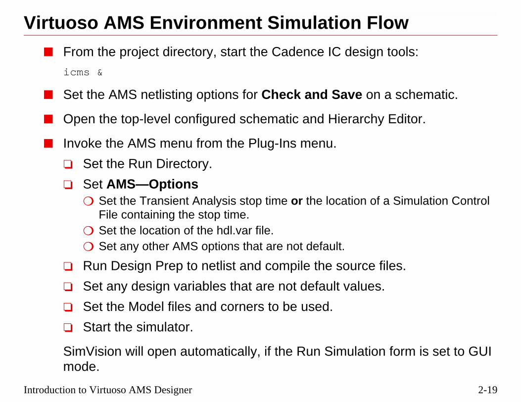
Virtuoso AMS Environment Simulation Flo■ From the project directory, start the Cadence IC design
icms &
■ Set the AMS netlisting options for Check and Save on a
■ Open the top-level configured schematic and Hierarchy
■ Invoke the AMS menu from the Plug-Ins menu.
❏ Set the Run Directory.
❏ Set AMS—Options❍ Set the Transient Analysis stop time or the location of a
File containing the stop time.❍ Set the location of the hdl.var file.❍ Set any other AMS options that are not default.
❏ Run Design Prep to netlist and compile the source fi
❏ Set any design variables that are not default values.
❏ Set the Model files and corners to be used.
❏ Start the simulator.
SimVision will open automatically, if the Run Simulationmode.

2-20
AMS Environment Simulation Flow
, elaborating, andS—Options menu.
3/10/05 Virtuoso AMS Designer
When the Hierarchy Editor is used, many of the options for compilingsimulation are preset as defaults. They can be modified under the AM

2-21
ws used in aell.
g-Ins Menu
Introduction to Virtuoso AMS Designer
The Hierarchy Editor■ The Hierarchy Editor displays the libraries, cells, and vie
design, and simplifies switching the view used for any c
Toolbar
Global
Cell Bindings
Messages
Bindings
PluAMS Menu

2-22
Hierarchy Editor
ngs to librariesw found in the list
3/10/05 Virtuoso AMS Designer
The Cell Bindings above are displayed in Table View (default).
The Global Bindings provide priority search lists to resolve cell bindi(Library List) and view bindings to cells (View List). The first cell vieorder will be reported in the Cell Bindings list.

2-23
each cell.
and clicking theed in to replace the
ectre netlists andMS modules
Introduction to Virtuoso AMS Designer
Binding Cells to ViewsThe Hierarchy Editor selects the views to be used (bound) for
■ By placing the mouse pointer at a cell bindings line itemright mouse button, another (existing) view can be switchone in the binding list.
■ Cells can also be bound to non-compiled SPICE and SpVerilog-A modules (Source file) or Verilog and Verilog-A(Reference Verilog).
2-24
Binding Cells to Views
mode by selectingy) on the resultingy pulling down to
3/10/05 Virtuoso AMS Designer
Schematics and modules can be opened in editing mode or read-only them and, with a right click, pulling down to Open or Open (Read-Onlmenu. Once changed and saved, the modified cell can be re-compiled bCompile Netlist.

2-25
Erce file as the Set
e
Introduction to Virtuoso AMS Designer
Binding Netlist Text Files to Cells in the HBind SPICE, Spectre and Verilog-A modules by selecting SouCell View, and browsing to the file.
1. Select Source File 2. Browse to fil
3. Resulting binding

2-26
3/10/05 Virtuoso AMS DesignerThe warning at the bottom of the Messages window can be ignored.

2-27
s in the HE5.X structures for
ctory.
3. SelectLibrary andView
Introduction to Virtuoso AMS Designer
Binding Behavioral Verilog/A/AMS to CellBind Verilog, Verilog-A and Verilog-AMS modules, and createthem by selecting Reference Verilog as the Set Cell View.
This method compiles into the run directory, not the work dire
1. Select Reference 2. Browse to File
4. Resulting Binding
Verilog
2-28
piling, set the
g file.
3/10/05 Virtuoso AMS Designer
To set up run directories to receive the results of the netlisting and comfollowing variables in the project ams.env file before starting icms:amsDirect netlistToRunDir boolean t
amsDirect useRunDirNetlistOnly boolean nil (or t)
The binding information will be stored in the config view as a prop.cf

2-29
can be compiledatewhich they should
Introduction to Virtuoso AMS Designer
Compiling Verilog/A/AMS LibrariesVerilog, Verilog-A or Verilog-AMS modules in files or librariesinto 5.X libraries from the Hierarchy Editor using File—PopulLibrary—Verilog, selecting the files to compile, the library intobe compiled, and the view name to use.
1. Select2. Browse
4. Select Binding Normally
3. SelectLibrary andView

2-30
3/10/05 Virtuoso AMS Designer
2-31
a tree view instead
e instance of a cell
Introduction to Virtuoso AMS Designer
Cell Binding Tree View■ The Cell Bindings to instance views can be displayed in
of a list view by clicking on the Tree View icon.
■ The Tree View can be used to change the binding of onbut not other instances of the same cell.

2-32
Cell Binding Tree View
ock has been set toms view.
3/10/05 Virtuoso AMS Designer
■ In the above example, the first comparator in the comp_array blschematic view, while the second comparator uses the veriloga
■ To return to the Table View, click on the Table Icon:

2-33
without changingred cells.
, right-click with the
ding form, select a
Introduction to Virtuoso AMS Designer
Occurrence Binding■ Individual occurrences of cell instances can be changed
other instances with the same instance name in m-facto
❏ From the Tree View, select the occurrence to changemouse, and select Add Occurrence Binding.
❏ From the Browse window of the Add Occurrence Bindifferent view for that specific occurrence.

2-34
Occurrence Binding
ach “comp_array”
of the comparatoromparator view in
view of the I1ay to be differente comp_array.
3/10/05 Virtuoso AMS Designer
■ In the above example, there are two “comparator” cells within ecell, of which there are two in the “comp_top” design.
❑ Setting the Instance View to “schematic” for the I0 instance in the I0 instance of the comp_array will also change that I0 cto the I1 instance of the comp_array.
❑ Adding an Occurrence Binding, on the other hand, allows theinstance of the comparator in the I1 instance of the comp_arrthan the I1 instance of the comparator in the I0 instance of th

2-35
ted by clicking on
Introduction to Virtuoso AMS Designer
Saving Cell Bindings and Configurations■ After any change in cell bindings, the form must be upda
the Update Icon.
■ To save the configuration, execute File—Save.
Update Icon

2-36
Saving Cell Bindings and Configurations
3/10/05 Virtuoso AMS Designer
2-37
design to be
itor. The files the elaborator
ol;
onal,
, ahdl;
ic;
;
havioral;
Introduction to Virtuoso AMS Designer
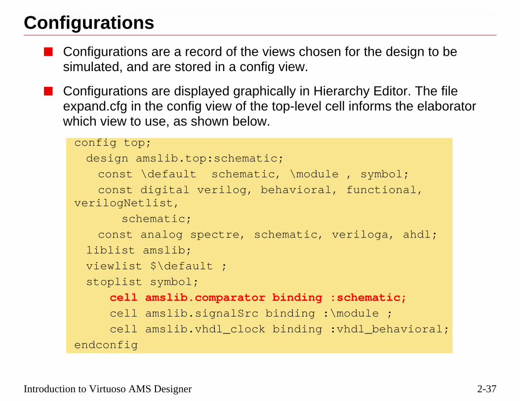
Configurations■ Configurations are a record of the views chosen for the
simulated, and are stored in a config view.
■ Configurations are displayed graphically in Hierarchy Edexpand.cfg in the config view of the top-level cell informwhich view to use, as shown below.
config top;
design amslib.top:schematic;
const \default schematic, \module , symb
const digital verilog, behavioral, functiverilogNetlist,
schematic;
const analog spectre, schematic, veriloga
liblist amslib;
viewlist $\default ;
stoplist symbol;
cell amslib.comparator binding :schemat
cell amslib.signalSrc binding :\module
cell amslib.vhdl_clock binding :vhdl_be
endconfig

2-38
Configurations
ction as choosing
needs to bebinding <arg>
m within thet easier.
3/10/05 Virtuoso AMS Designer
■ Config views bind the views to the cells, and serve the same funthe view to descend into from a Composer schematic.
■ Using a config view is required when:
❑ There is more than one view of a cell, because the elaboratorinstructed which view to choose. (For Verilog modules, the -option can be used.)
❑ Using the Hierarchy Editor.
❑ There are Verilog-AMS netlists from a schematic.
■ Using the Hierarchy Editor, either standalone (hierEditor) or froVirtuoso AMS Environment, makes configuration selection a lo

2-39
fferent simulation
from Plug-ins, thee Run Directory.
Newrectory
ld Runry
Introduction to Virtuoso AMS Designer
Run Directories■ Run directories can be used to store the outputs from di
runs for later comparison or reference.
■ When first opening the Hierarchy Editor and setting AMSonly AMS action allowed from the AMS Menu is to set th
CreateRun Di
Use ODirecto

2-40
Run Directories
n directory can beectory (CWD),
ored
3/10/05 Virtuoso AMS Designer
■ The Hierarchy Editor requires one run directory to be set. The rulocated anywhere, but cannot be set to the Current Working Dirwhich is the project directory from which icms was invoked.
■ Run directories will receive:
❑ simulation output files
❑ log files produced during the simulation flow
❑ environment files related to form settings
❑ waveform data
■ Run directories may also contain:
❑ hdl.var files
❑ Simulation Control Files
❑ SimVision script files
■ The working library (defined as WORK in hdl.var) contains:
❑ The .pak file, where the compiled netlists and modules are st
❑ The compiled units in a lib.cell:view directory structure
2-41
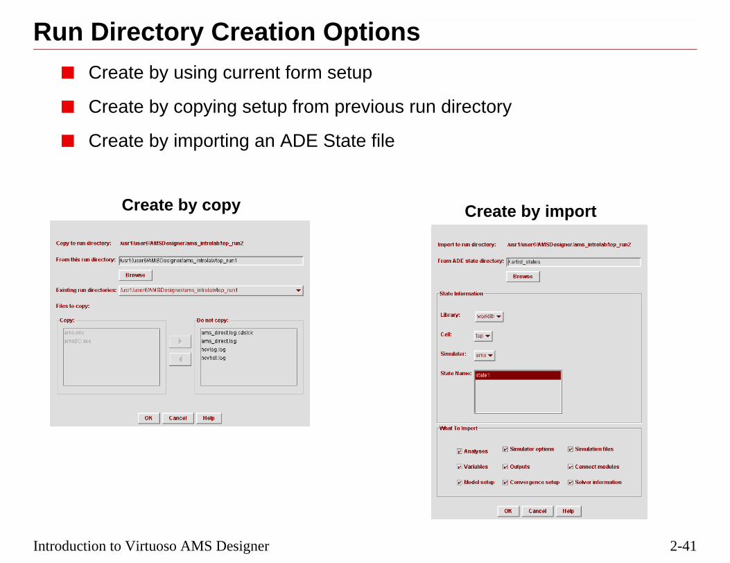
import
Introduction to Virtuoso AMS Designer
Run Directory Creation Options■ Create by using current form setup
■ Create by copying setup from previous run directory
■ Create by importing an ADE State file
Create by copy Create by
2-42
3/10/05 Virtuoso AMS Designer
2-43
rarchy Editor usingnalysis form or by
Introduction to Virtuoso AMS Designer
Setting the Simulation Stop Time■ The Simulation Stop Time can either be set from the Hie
the AMS—Options—Simulation—Analog Solver—Tran Aediting the Simulation Control File.

2-44
Setting the Simulation Stop Time
laced in a
control file” box,cs.
he file extension
3/10/05 Virtuoso AMS Designer
■ A stop time, along with other simulation control cards, can be pSimulation Control File in the project or run directory.
❑ If a Simulation Control File is used, check the “Use simulationand set the path to the file, which will have a file extension .s
❑ Be careful not to select a Spectre model file, which also has t.scs.

2-45
t from the
ation of hdl.var
Introduction to Virtuoso AMS Designer
Setting the hdl.var LocationFrom the Hierarchy Editor, the location of the hdl.var file is seAMS—Options—Compiler form.
Loc

2-46
Setting the hdl.var Location
compiling, which
during elaborationve model sections,
3/10/05 Virtuoso AMS Designer
■ One hdl.var file must be located in the CWD, and is used duringis done from the CWD.
■ Additional hdl.var files may be located in the run directory, usedand simulation. These hdl.var files may refer to different primitifor example.

2-47
rce files.
files that haven’tsted.
the files being
etting is often usedhas been updated,hanged.
Introduction to Virtuoso AMS Designer
Design PrepDesign Prep performs the netlisting and compiling on the sou
■ Netlist
❏ Incremental is default, meaning to only netlist thosebeen netlisted, or have been updated since last netli
❏ All means to netlist all project files.
■ Compile
❏ When netlisting is default, meaning to only compilenetlisted.
❏ All cellviews means to compile all project files. This son the first Design Prep operation, or if the compileror if modules that are not subject to netlisting have c

2-48
Design Prep
er of netlistsr of global signalsefore simulation
3/10/05 Virtuoso AMS Designer
In AMS Designer, netlisting is hierarchical rather than flattened.
When Design Prep is finished, a report is displayed showing the numbgenerated, the number of netlists or modules compiled, and the numbeand design variables found. If errors are reported, they must be fixed bcan proceed.
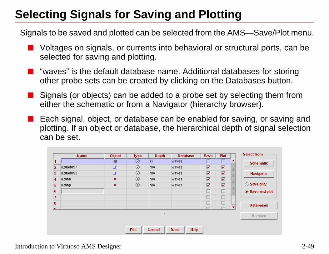
2-49
—Save/Plot menu.
ural ports, can be
ses for storingbases button.
cting them fromser).
ing, or saving andof signal selection
Introduction to Virtuoso AMS Designer
Selecting Signals for Saving and PlottingSignals to be saved and plotted can be selected from the AMS
■ Voltages on signals, or currents into behavioral or structselected for saving and plotting.
■ “waves” is the default database name. Additional databaother probe sets can be created by clicking on the Data
■ Signals (or objects) can be added to a probe set by seleeither the schematic or from a Navigator (hierarchy brow
■ Each signal, object, or database can be enabled for savplotting. If an object or database, the hierarchical depth can be set.

2-50
Saving and Plotting Signals
n Browser.
rts in
on the simulation
SimVision is
when the
isplayed in the
ent User Guide,
3/10/05 Virtuoso AMS Designer
■ Signals for plotting can also be selected in the SimVision DesigCross-selection from the schematic is also possible.
■ Enable the saving and plotting of currents into terminals and poAMS—Options—Waveforms.
■ The effect of checking both the Save and Plot columns dependsRun Mode setting:
❑ In the GUI mode, the selected waveforms are marched once started.
❑ In the Batch mode, the waveforms are saved and then plottedsimulation completes.
❑ In the Tcl mode, the waveforms are only saved.
■ The colors highlighted on the schematic will match the colors dwaveform viewer.
■ More information on Save/Plot is in the Virtuoso AMS EnvironmChapter 11, “Elaborating, Simulating, and Plotting Results.”
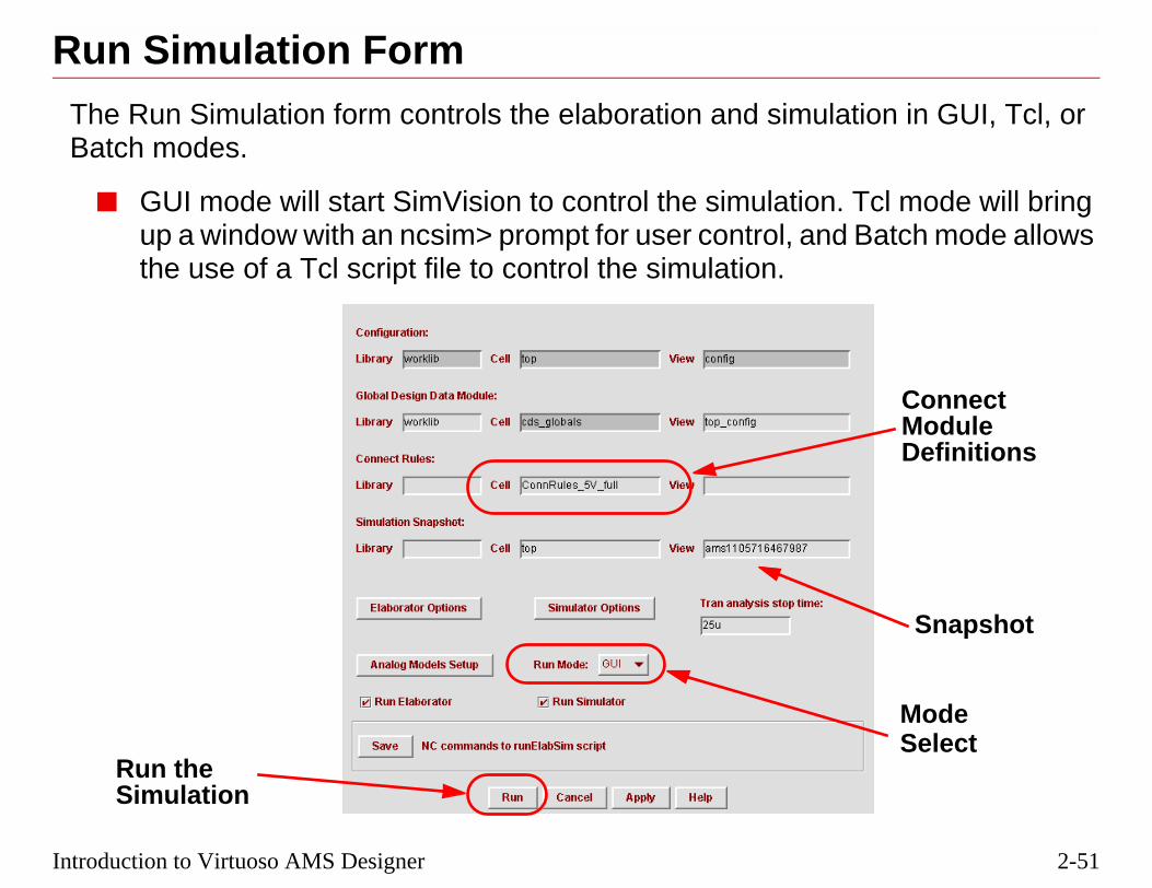
2-51
ion in GUI, Tcl, or
Tcl mode will bringBatch mode allows
ConnectModuleDefinitions
Snapshot
ModeSelect
Introduction to Virtuoso AMS Designer
Run Simulation FormThe Run Simulation form controls the elaboration and simulatBatch modes.
■ GUI mode will start SimVision to control the simulation.up a window with an ncsim> prompt for user control, andthe use of a Tcl script file to control the simulation.
Run theSimulation

2-52
Run Simulation Form
nts, arelaboration to
in this example is
ey can be made asvided with the
n be copied or in the project.
or errpreset, for
ulation. The cellhe view is seeded
ce.
n and simulation
3/10/05 Virtuoso AMS Designer
■ Connect Modules, sometimes referred to as Interconnect Elemeautomatically placed between analog and digital blocks during etranslate analog to digital and vice-versa.
❑ The connect rule search begins in the working library (whichworklib) and then follows the library order in cds.lib.
❑ Because Connect Modules are written as Verilog modules, thsimple or complex as desired. The example shown is one proinstalled software.
❑ The AMS install directories include several examples that careferenced, but the user can write their own and include them
■ If you are only changing a simulation control such as stop time example, elaboration can be disabled to reduce simulation time.
■ The Snapshot stores the initial conditions and signals for the simname for the snapshot defaults to the top-level design cell name. Twith a time stamp, and can be changed for the user’s convenien
■ Saving NC commands to a runElabSim file saves the elaboratiocommand setup to be run in Tcl or batch mode.

2-53
erBrowser, where
sole
Introduction to Virtuoso AMS Designer
The SimVision Console and Design BrowsRun Simulation brings up the SimVision Console and Design signals can be selected for sending to the Waveform viewer.
Con
ScopeSignal List
Menu BarToolbar
Tree
Design Browser
Simulation Control
I/O Region
SimulationControl

2-54
The SimVision Console and Design Browser
aveform viewer asally using the saved and
item.
atic Editor,sign Browser.
er can be found in
description of the
3/10/05 Virtuoso AMS Designer
■ Signals can be selected in the Design Browser and sent to the Wa group, or Drag and Dropped to the Waveform viewer individumiddle mouse button, or custom probes (a group of signals to bedisplayed) created from the Simulation—Create Probes menu
■ If Options—Editor—Cross Selection is set to On in the Schemselecting signals in the schematic will also select them in the De
■ More information on the SimVision Console and Design Browsthe SimVision User Guide in CDSDoc.
■ Consider taking the NC-Verilog Simulator course for a completeSimVision control panels and options.

2-55
ther windows.
erc tracerter window
sion calculator
ed scope
Introduction to Virtuoso AMS Designer
SimVision Tool Selection ButtonsMost SimVision control panels can send selected signals to o
Tool Selector
Send to design browserSend to waveform window
Send to source browsSend to schemati
Send to regis
Send to expres
Add selected object to this window
Properties
Select all scopes below currently select

2-56
SimVision Tool Selection Buttons
custom
urrently digital
hical design
3/10/05 Virtuoso AMS Designer
■ The register window permits sets of signals to be displayed in arepresentation of a design flow.
■ The signal flow browser allows tracing the drivers of a signal (csignals only) back through the hierarchy.
■ The schematic tracer will construct a block diagram of a hierarcshowing the interconnects.

2-57
from the Console
ion Control
oint
ime 0
ent,
tement,
calls
program calls
on an object
mulation timel Indicator
Introduction to Virtuoso AMS Designer
SimVision Simulation Control ButtonsSimulation control can be done from most windows, as well asusing Tcl commands.
Simulat
Run the simulation until the next breakpInterrupt the simulator
Reset the simulation back to t
Run one behavioral statem
Run one behavioral sta
stepping into subprogram
stepping over any sub
Set a breakpoint
Current siAnalog/Digita
Move cursor to next edgeMove cursor to previous edge
Enable marching waveforms

2-58
SimVision Simulation Control Buttons
er or digital solver
3/10/05 Virtuoso AMS Designer
The Analog/Digital Indicator switches to show whether the analog solvis currently active.

2-59
er or Probe
well as digital
Toolbar
Buttons
Vertical
Controls
HorizontalStretch
Zoom
Zoom
Introduction to Virtuoso AMS Designer
The SimVision Waveform Viewer■ The signals are selected for display in the Design Brows
windows.
■ The SimVision Waveform viewer can display analog as waveforms synchronized in time.
MenuBar
Signals
Vertical
andScale
Stretch
SidebarPanels

2-60
The SimVision Waveform Viewer
g., simvision.sv.
hortcuts under
en. Analog colors
e started by typingo bring up the
thematicalator button on the
ting the signal,ring a value.
l Options, whichs opened.
n the nextplication State,e same settings or
3/10/05 Virtuoso AMS Designer
■ Default buttons can be customized using a configuration file, e.
■ Bindkeys can be set under Edit—Preferences: select Keyboard SGeneral Options and Waveform Window.
■ Analog signals are displayed in yellow, and digital signals in grecan be changes using Format—Color.
■ From the UNIX prompt, the SimVision Waveform viewer can bsimvision to bring up the Design Browser, or simvision -waves tSimVision Waveform viewer itself.
■ An Expression Calculator is included to perform logical and maoperations on signals and can be invoked by pressing the CalculToolbar.
■ Horizontal reference lines can be set for analog signals by selecright-clicking, pulling down to Create Reference Line, and ente
■ To print a waveform display, execute File—Print Window.
■ Set the X-axis time scaling units in Edit—Preferences—Generawill become active the next time SimVision waveform viewer i
■ SimVision settings can be automatically saved and restored upoinvocation under Edit—Preferences—General Options, Save Apand Restore Application State. If the user does not want to use thsignals as before, these options should be turned off.

2-61
can be accessedBrowser window,.
Introduction to Virtuoso AMS Designer
SimVision Sidebar PanelsThe Design Browser, Design Search, or Trace Signal panels from the sidebar controls within a Waveform window, Source Schematic Tracer, Register window, or Expression Calculator
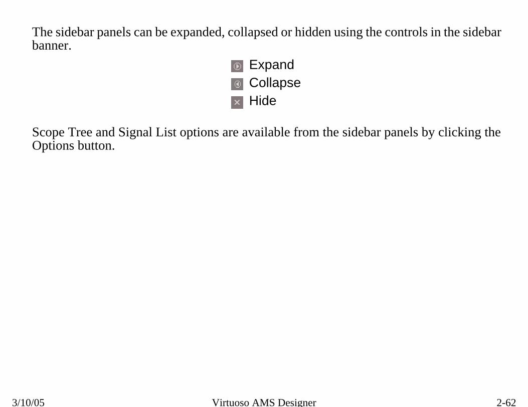
2-62
SimVision Sidebar Panels
trols in the sidebar
els by clicking the
3/10/05 Virtuoso AMS Designer
The sidebar panels can be expanded, collapsed or hidden using the conbanner.
Scope Tree and Signal List options are available from the sidebar panOptions button.
ExpandCollapseHide

2-63
l. Hovering over an in the module in
nation pop-up
Introduction to Virtuoso AMS Designer
Trace Signals PanelThe Trace Signals panel shows the drivers or loads for a signadriving or loading signal pops up an explanation of the locatiowhich it is set.
ExplaLoads for theselected signal

2-64
3/10/05 Virtuoso AMS Designer
2-65
gnals to group andy right clicking and.
selected signal
Zoom All tofit Y Axis
Click Menu
Introduction to Virtuoso AMS Designer
SimVision Signal Formatting■ Formatting the signals is done by a combination of:
■ Grouping signals can be done by selecting the desired siusing buttons in the toolbar, executing Edit—Create, or bselecting the desired type of group from a pop-up menu
❏ The Zoom buttons
❏ Horizontal Stretch sliders
❏ The Analog Waveform controlson the right side of each analogwaveform for Vertical Zoom,and on the left side for Stretch
❏ Pop-up menus activated by a mouse right-click on a
Zoom In,Zoom Out
Zoom to fitX Axis
Create BusCreate Group Ungroup Right

2-66
SimVision Signal Formatting
nto a singlesitions. The radixc.
se Bus.
be created to shown a different color.
3/10/05 Virtuoso AMS Designer
■ Creating a bus on a group of digital signals will combine them iwaveform showing the transition times and values between tranof the values can be changed using Format—Radix/Mnemoni
Reversing the order of a digital bus is done by Format—Rever
■ For analog signals of similar magnitudes, an analog overlay cantheir coincidence or differences. Each signal will be displayed i

2-67
Virtuoso AMS
ed simulation flow?
in the Hierarchy
Introduction to Virtuoso AMS Designer
Mid-Point Review1. What languages does Virtuoso AMS Designer support?
2. What are some of the files needed for a simulation with Designer?
3. What are the three basic steps in the command-line-bas
4. What button needs to be pressed after changing a viewEditor?

2-68
Mid-Point Review
re, SPICE
3/10/05 Virtuoso AMS Designer
1. Verilog, VHDL, Verilog-A, Verilog-AMS, VHDL-AMS, Spect
2. cds.lib, hdl.var, filename.scs, ./worklib
3. Compile, elaborate, simulate
4. Update

2-69
Introduction to Virtuoso AMS DesignerLab
Lab 2-1 Introduction to Virtuoso AMS Designer

2-70
Lab
3/10/05 Virtuoso AMS Designer
Use the workstations to perform the lab exercises.
Refer to the lecture notes for helpful information.

2-71
ulation. Therefore,an a SPICE or
tlist, so netlisting
ic using one of the
matic window with(Command
and select
s—AMS—Netlist).
Introduction to Virtuoso AMS Designer
Schematic Netlists■ Virtuoso AMS Designer uses Verilog-AMS netlists for sim
schematics need to have a Verilog-AMS netlist, rather thSpectre netlist.
■ AMS generates hierarchical netlists, rather than a flat necan be done incrementally.
■ A verilog.vams netlist can be generated from a schematfollowing methods while in the Environment:
❏ Perform a Check and Save from the Composer schethe AMS Check and Save options set from the CIW Interpreter Window).
❏ Execute AMS—Design Prep in the Hierarchy EditorIncremental or All.
❏ Use AMS Netlister from the CIW Options menu (Tool

2-72
Schematic Netlists
line to netlist a
etlists, need to beg compilation.
3/10/05 Virtuoso AMS Designer
■ The amsdirect command can be used from the UNIX commandschematic.
■ Primitive libraries, or components that appear in verilog.vams ncompiled into lib.cell:view format using the -use5x option durin

2-73
e information with
s)
netlist syntax:
netlist******
.vcc) v1(a,gnd);, b);c, c);, b, gnd);
Introduction to Virtuoso AMS Designer
Spectre vs. Verilog-AMS Netlists■ Spectre and Verilog-AMS netlist statements have the sam
a different syntax.
❏ Spectre:instance (nodes) model_name parameters
❏ Verilog-AMS:model_name #(parameters) instance (node
■ The following chart compares Spectre and Verilog-AMS
**A simple Spectre netlist**
global gndv1(a gnd) vsource dc=vccrb(a b) resistor r=100rc(vc c) resistor r=1kq1(c b gnd) mybjt area=2...
******The same Verilog-AMS
ground gnd;vsource #(.dc(cds_globalsresistor #(.r(100)) rb(aresistor #(.r(1k)) rc(vmybjt #(.area(2)) q1(c...

2-74
Spectre vs. Verilog-AMS Netlists
ferent syntax. Forllowing in SPICE:
tes for the devices,
e (nodes)
3/10/05 Virtuoso AMS Designer
■ A SPICE netlist is similar to a Spectre netlist, with a slightly difexample, the resistor in the netlists above would look like the forb a b 100
■ verilog.vams netlists generated from a schematic will add attribuincluding library bindings and global connections:model_name #(parameters) (*attributes*) instanc

2-75
and parametersglobals module forrt of the design.
Introduction to Virtuoso AMS Designer
cds_globals ModuleDuring Design Prep from the Hierarchy Editor, global signals from netlists are automatically collected and placed in a cds_use by the simulator. This module will also be compiled as pa
// Verilog-AMS cds_globals module for top-level cell:// worklib/top.// Generated by AMS Design Prep.// Cadence Design Systems, Inc.
‘include “disciplines.vams”
module cds_globals;
// Global Signals wire \vdd! ; wire \vss! ; electrical \gnd! ; ground \gnd! ;
// Design Variables dynamicparam real idc = 10u;
endmodule

2-76
Cds_Globals
t the beginning ofthe tool creates anetlisting process.rilog-AMS file. Ifre global, they canenu.
3/10/05 Virtuoso AMS Designer
A SPICE or Spectre netlist would list the global signals (vdd!, gnd!) athe netlist. Because Virtuoso AMS Designer netlists are hierarchical, single cds_globals file that lists all the global signals found during theThis cds_globals file is compiled into the design just like any other Vethere are global signals that do not use the “!” symbol to indicate they abe added in the Global Signals form in the Hierarchy Editor’s AMS m

2-77
at any level of the
nged using thence.
ser.
nal name with the
Introduction to Virtuoso AMS Designer
The SimVision Source Browser■ The Source Browser displays the netlist or source code
hierarchy.
❏ The scope (hierarchy level) of the display can be chacyclic field selector, or by double-clicking on an insta
❏ Breakpoints can be set on objects in the source brow
❏ Signal values can be read by “hovering” over the sigmouse cursor.

2-78
The SimVision Source Browser
rm viewer using
eform viewer, and
3/10/05 Virtuoso AMS Designer
Signals in the Source Browser can be selected and sent to the Wavefodrag and drop with the middle mouse button.
Highlighting a signal in the Source Browser will highlight it in the Wavvice-versa.
The browser can be set to continuously display object values underView—Display Values:

2-79
ing and displaying
lect signals insign Browser orurce Browser click on the
d button.
Introduction to Virtuoso AMS Designer
Creating Signal Probes in SimVisionGroups of signals can be combined into a custom probe for savby executing Simulation—Create Probe.
Sends signals toWaveform display
SeDeSoandAd

2-80
Creating Signal Probe in SimVision
f SimVision.
3/10/05 Virtuoso AMS Designer
Creating probes is similar to the Watch window in previous versions o

2-81
Introduction to Virtuoso AMS DesignerSetting BreakpointsExecute Simulation—Set Breakpoint—<Pick Type>
Simulation Menu

2-82
Setting Breakpoints
3/10/05 Virtuoso AMS Designer
■ Breakpoints can be set (even on analog objects) for:
❑ Time (exact, repetitive, delayed)
❑ Line (number)
❑ Signal (changes)
❑ Condition
❑ Process
❑ Subprogram

2-83
roperties form.
m.
Introduction to Virtuoso AMS Designer
Showing BreakpointsExecute Simulation—Show—Breakpoints to bring up the P
Breakpoints can be enabled, disabled or deleted from this for

2-84
Showing Breakpoints
useful information
3/10/05 Virtuoso AMS Designer
■ The SimVision Properties form also allows the display of otherregarding the simulation database.

2-85
with interconnects.
Introduction to Virtuoso AMS Designer
SimVision Schematic TracerThe Schematic Tracer constructs a block diagram of a design

2-86
SimVision Schematic Tracer
window.
3/10/05 Virtuoso AMS Designer
■ Use drag and drop to send a signal of interest to the Waveform
■ To expand a block, select it and execute Edit—Fill Modules.

2-87
anges for selectedy.
rchy in a PLL.
Introduction to Virtuoso AMS Designer
SimVision Register WindowThe Register Window allows the user to track signal value chsignals, but also to arrange them in a custom graphical displa
■ Drawing tools are available from the right side tool bar.
■ The example below displays three levels of signal hiera
2-88
SimVision Register Window
3/10/05 Virtuoso AMS Designer

2-89
cuting File—Openct dialog or
ulations available
thee to on, 1, or yes to open simulationconnections.
entering ncsime stored iny theble.
Introduction to Virtuoso AMS Designer
SimVision Remote Connections■ Connections can be made to running simulations by exe
Simulation, or from the command line, simvision -connesimvision -connect pid.
❏ The Open Simulation form will display the current simfor connection:
■ To control visibility of your simulation to other users, setLDV_SIMVISION_CONNECTIONS environment variablenable (default); to hidden so that it is not visible on theform, but accessible; or off, 0, or no to prevent external
■ To password-protect your simulation, set a password by-password and adding a password. The password will b$HOME/.simvision/passwd, or to the location specified bLDV_SIMVISION_PASSWORD_FILE environment varia

2-90
SimVision Remote Connections
om the commandit is running, and
3/10/05 Virtuoso AMS Designer
Remote connections are useful when you start a lengthy simulation frline (no GUIs), and then want to connect into it from a GUI to see howcontrol it remotely.

2-91
vel Schematic
Introduction to Virtuoso AMS Designer
Lab
Lab 2-2 Replacing a Behavioral Model with a Transistor-Le
2-92
Lab
3/10/05 Virtuoso AMS Designer

®
March 10, 2005
Module 3
3 Command- trol of Virtuoso AMS Designer
Line Con
3-2
3/10/05 Virtuoso AMS Designer
3-3
Command-Line Control of Virtuoso AMS DesignerTopics in this Module■ Virtuoso® AMS Designer command-line usage
■ Simulation Control Files
■ Command-line options
■ AMS library structure and .pak files
■ Configurations
■ Custom netlisting
■ Tcl commands
■ UNIX scripts
■ Saving and restarting

3-4
Command Line Control of Virtuoso AMS Designer
and line, as well
l environment,signer provides
l AMS Designer
re about what goesironment.
3/10/05 Virtuoso AMS Designer
■ Virtuoso AMS Designer can be controlled from the UNIX commas from Hierarchy Editor in the AMS Environment.
■ Some designers prefer a text-based environment over a graphicawhile others prefer graphical over text-based. Virtuoso AMS Deboth.
■ This lesson will focus on the commands and options that controfrom the command line, and by extension, through batch files.
■ Through studying the command format, you will understand moon underneath the graphical windows of the Virtuoso AMS Env

3-5
r)
MS extensions)
ntrol, debug, and
ontrol & Display
SimVision:ConsoleDesign BrowserSource BrowserWaveformBreakpointsSignal FlowSchematic TracerMeasurementCalculator
Command-Line Control of Virtuoso AMS Designer
Virtuoso AMS Designer Tool Flow■ ncvlog, ncvhdl—Verilog® and VHDL compilers
■ ncelab—mixed-language, mixed-signal elaborator (linke
■ ncsim—mixed-language, mixed-signal simulator (with A
■ SimVision—mixed-language, mixed-signal simulation codisplay
module diginv(out,in);input in;output out;logic in, out;
assign #1 out = ~in;endmodule
wire out;module ring;
diginv d1(d,fb);anainv a1(a,d);diginv d2(fb,a);
endmodule
module anainv(out,in);input in;output out;electrical in,out;real vthres = 2.5;
analog begin....
endendmodule
module diginv(out,in);input in;output out;logic in, out;
assign #1 out = ~in;endmodule
wire out;
Compile Simulate CElaborate
Simulationsnapshot (sss)_Spectresimulationimage (ssi)

3-6
Virtuoso AMS Designer Tool Flow
itecture, and is ais provides a speedbase (called a .pak
, which permitse recompilation of
er), andital blocks to
design, which is
Spectre® binaries,
here can be
3/10/05 Virtuoso AMS Designer
■ Virtuoso AMS Designer is built on NC-Sim and the INCA archcompiled simulator, rather than interpreted as in legacy tools. Thadvantage since the elaboration is performed on a a unified datafile) containing pre-compiled source files.
■ Virtuoso AMS Designer, like NC-Sim, uses compiled input dataupdating and recompiling of one source file without requiring ththe entire database.
■ Elaboration connects all the source modules together (like a linkautomatically inserts Connect Modules between analog and digtranslate the signals from one domain to the other.
■ The Elaborator also creates a snapshot of the initial state of the used by the simulation engine.
■ Simulation is performed by one kernel, combining NC-Sim andfor the highest performance.
■ The snapshot contains the initial conditions for the simulation. Tmultiple snapshots corresponding to different testbenches.

3-7
Command-Line Control of Virtuoso AMS DesignerAMS Control Files■ Three required control files:
❏ cds.lib
❏ hdl.var
❏ <simulation_control_file>.scs
■ A directory associated with the required WORK library

3-8
AMS Control Files
bug utility in a
and note incorrect
uired for the ADE
elaborator. (Using stored in the run
file. The defaultc. The Currentd the search haltsd.
aths to cds.lib and
3/10/05 Virtuoso AMS Designer
■ cds.lib sets up the library structure.
❑ The cds.lib library structure can be tested using the cdsLibDedirectory containing a cds.lib file.
❑ The utility will list all the libraries being used and their paths,or missing paths.
❑ At the UNIX command prompt, enter:cdsLibDebug -cla
■ hdl.var sets some common variables and options, and is not requse model.
■ <simulation_control_file>.scs controls the analog simulation.
■ The WORK directory stores all the outputs from the compiler andthe AMS Environment, the elaborator and simulator outputs aredirectory.)
■ The search order for cds.lib and hdl.var is defined by a setup.locsetup.loc file can be found in install_dir/share/cdssetup/setup.loWorking Directory (CWD) is usually the first to be searched, anat the first location in the list where cds.lib and hdl.var are foun
■ Command-line options -cdslib and -hdlvar allow the setting of phdl.var, which will override the search order.

3-9
ite-protected
temporary writableP)
t/analogLib
ample
Command-Line Control of Virtuoso AMS Designer
The cds.lib File■ A required file in the project directory
■ Defines the physical location of accessible libraries
■ Can assign explicit temporary writable directories for wrlibraries
Compiling write-protected library cells without an explicitdirectory defined will write to the work library (implicit TM
■ Can be easily copied from other projects and updated
SOFTINCLUDE $AMSHOME/tools/inca/files/cds.lib
DEFINE workLib ./worklib
DEFINE analogLib $CDSHOME/tools/dfII/etc/cdslib/artis
DEFINE basic $CDSHOME/tools/dfII/etc/cdslib/basic
DEFINE sample $CDSHOME/tools/dfII/etc/cdslib/artist/s
ASSIGN sample TMP ./diglib
DEFINE sharedlib $SHAREDLOC/analog_ip_lib
ASSIGN sharedlib TMP ./mylib
ASSIGN AllLibs TmpRootDir ./myTMPs

3-10
The cds.lib File
’s .cshrc file to theMS Environment.
CLUDE will give
d files will beust exist in thed as WORK in the
of modified cellsust be capitalized.ported.
y, then an implicitory containing the
t for explicitlyd, instead of the
the setting of thetten to the run
3/10/05 Virtuoso AMS Designer
■ AMSHOME and CDSHOME are UNIX variables set in the userinstall directory for the Virtuoso AMS Simulator and Virtuoso A
■ SOFTINCLUDE means to include the file if it can be found. INan error if the file cannot be found.
■ workLib is the working library in this project where the compilestored, except as noted below. The physical directory worklib mproject directory. The library alias workLib will be further aliasehdl.var file.
■ The ASSIGN statement adds an explicit library for local storagefrom a write-protected library (either digital or analog). TMP mThe assigned writable directory must exist or an error will be re
❑ If an explicit library is not defined for a write-protected librarlibrary will be created in the working library, or in the direct.pak file.
❑ If AllLibs TmpRootDir is used, then all new compiles (excepdefined TMP libraries) will be saved to the directory specifieworking directory.
■ Using implicit TMP libraries in the AMS Environment requiresnetlistToRunDir variable to t, and the compiled files will be wridirectory rather than the work directory.

3-11
E use model).
h -use5x
TS -linedebug
VIEW_MAP
> veriloga)
piled into specifict mapped:
worklib
Command-Line Control of Virtuoso AMS Designer
The hdl.var File■ A required file in the project directory (except for the AD
■ Sets variables used by the various AMS tools
❏ Default output library, WORK
❏ Can set library format to lib.cell:view as a default wit
❏ Default command-line options, such as NCVLOGOP
❏ Correlates Verilog file extensions to views through a
■ Typical hdl.var file:
SOFTINCLUDE $AMSHOME/inca/files/hdl.var
DEFINE WORK workLib
DEFINE NCVLOGOPTS -linedebug -use5x
DEFINE MODELINCDIR ./models
DEFINE MODELPATH gpdk.scs(NN)
DEFINE VIEW_MAP ($VIEW_MAP, .v => verilog, .va =
■ A library map can also be used to force libraries to be comdirectories, with the default library mapping for those no
DEFINE LIB_MAP (dir1 => lib1, dir2 => lib2, + =>

3-12
The hdl.var File
.lib.
manner that allowsn Source Browser
ts and in the
less als.
compiled views.ple), when
the .pak file with
3/10/05 Virtuoso AMS Designer
■ -use5x sets the static library structure to lib.cell:view.
■ The WORK variable is set to the working library alias set in cds
■ NCVLOGOPTS -linedebug tells ncvlog to compile the code in asetting breakpoints in the analog and digital code in the SimVisiowindow. (NCVHDLOPTS is the VHDL equivalent.)
■ MODELINCDIR sets the path for included model files in netlisMODELPATH definition.
■ MODELPATH sets the file name (with path for Eden usage, unMODELINCDIR is defined) for any Spectre primitives or mode
■ The View Map defines the mapping between file extensions andThe mapping forces any file with a given extension (.v, for examcompiled with ncvlog or ncvlog -ams commands, to be stored inthe view it is mapped to (verilog, for example).

3-13
simulation whenSpectre Control
=”tran1.tran”
0 cmin=10f
Command-Line Control of Virtuoso AMS Designer
The Simulation Control File■ Is a required file in the project directory for mixed-signal
running from the command line, with an extension .scs (Syntax)
■ Contains Spectre® analog simulation control cards:
❏ Outputs to be saved
❏ Transient stop time
❏ Initial conditions
❏ Simulator options (such as reltol)
A typical .scs Simulation Control file:
// the first line needs to be blank
simulator lang=spectre
saveNodes options save=selected rawfmt=sst2 rawfile
tran1 tran stop=14us errpreset=moderate maxiters=1
save I1.I5.M1:all

3-14
The Simulation Control File
of the Virtuosoermines how long
within the AMSt in the Analog
the .scs extension.
ted instead of save
he setting affects
r SimVision)
format is done bypsfbinf.
3/10/05 Virtuoso AMS Designer
■ Only transient simulations are performed by the current release AMS Designer. The stop time in the Simulation Control File detthe analog solver will run.
■ A Simulation Control File template can be edited and saved fromEnvironment to customize each simulation, or have its values seSolver form.
■ Be careful not to reference a Spectre model file, which also uses
■ Spectre will save all the analog signals by default. If save = selec= all, then the signals to be saved need to be listed.
■ errpreset has three options: liberal, moderate, or conservative. Tthe degree of accuracy and conversely the simulation time.
■ Data can be saved in psfbin (for AWD) or sst2 (for WaveScan oformats.
❑ For example, saving waveforms in the compact psf waveformchanging the rawfmt option in the Simulation Control File to

3-15
ate the cds.lib andhe source files.
nals and top-level
bug.
e>.v top.v
Command-Line Control of Virtuoso AMS Designer
Command-Line Simulation Flow1. Create a project directory and a worklib subdirectory. Cre
hdl.var files in the project directory. Create, or copy in, tCreate the Simulation Control File <filename>.scs.
2. Create a testbench file, e.g., top.v, that provides input siginterconnects to the source files.
3. Compile the project files
ncvlog -ams <sourcefiles>.v top.v
ncvhdl -ams <sourcefiles>.vhd clock.vhd
4. Elaborate top
ncelab top [connectrules]
5. Simulate top invoking the SimVision control panel for de
ncsim -amslic top -gui -analogcontrol top.scs
home_dir/
project_dir/
worklib/ cds.lib hdl.var <filename>.scs <sourc

3-16
Command Line Simulation Flow
d included in the
iled without the
l simulations, and
ng Tcl commands
3/10/05 Virtuoso AMS Designer
■ Source files and command-line options can be listed in a file anncvlog or ncvhdl command using the -f filename option.
■ Purely digital source files without any AMS syntax can be comp-ams argument.
■ Connect Module files also need to be compiled for mixed-signaare then elaborated with the compiled design.
■ Simulations can be controlled, and digital waveforms saved, usifrom the ncsim prompt, or through the SimVision GUI.

3-17
source file unit
ut the compile
he design
on to a library other
“include
Command-Line Control of Virtuoso AMS Designer
Command-Line Options: ncvlog■ ncvlog [options] source_file
■ Options include:
❏ Add -ams to enable AMS compiling (ncvlog)
❏ Add -use5x to enable lib.cell:view library structure
❏ Add -file to include a list of files for compilation
❏ Add -specificunit to compile only one module from a containing several modules into a specifically named
❏ Add -view to compile a module into a specific view
❏ Add -linedebug to enable interactive line debug
❏ Add -mess[ages] to receive detailed information abo
❏ Add -update to compile only the out-of-date units in t
❏ Add -work to redirect the output of the compile operatithan the WORK library specified in the hdl.var file.
❏ Add -modelincdir to specify a list of include paths for<model_file>” statements in netlists.
■ A typical command-line invocation of ncvlog:
ncvlog -ams ./source/sareg.v -mess

3-18
Command Line Options: ncvlog
n the lib.cell:view
led unit, e.g.:erilog.vams
ining several
ource/files.v
dix A), type:
dited in the sourcenals. The use ofead involved.
Log File Browser
*E or *Wixed beforemay not affect the
3/10/05 Virtuoso AMS Designer
■ The -use5x option will create directories in the WORK library iformat.
■ The -view option overrides the default view naming for a compincvlog -ams -view schematic ./amslib/top/schematic/v
■ The -specificunit option compiles one module out of a file contamodules into a unit with a specific [lib.]cell[:view] name.
ncvlog -ams -specificunit testlib.clock:veriloga ./s
■ For a list of additional options (which is also provided in Appen
ncvlog -help
■ -linedebug saves the compiled modules in a way so they can be ebrowser, and so that force and deposit can be used on digital siglinedebug will impact the simulation speed because of the overh
■ To obtain information on an error or warning, use the Simulatorfrom the Virtuoso AMS Environment, or:
nchelp ncvlog ERROR_CODE
Note: The error or warning code is a 6/7-character mnemonic that follows thedisplayed when the tool being used reports a problem. Errors must be fproceeding. Warnings contain information about the tool’s progress thatsimulation results.

3-19
he design
entity beinger-level entity.
Command-Line Control of Virtuoso AMS Designer
Command-Line Options: ncvhdl■ ncvhdl [options] source_files
■ Options include:
❏ Add -ams to compile VHDL-AMS modules
❏ Add -use5x to utilize the lib.cell:view library structure
❏ Add -v93 to include checking by VHDL-93 rules
❏ Add -linedebug to enable interactive line debug
❏ Add -file <arg> to add a file list
❏ Add -update to compile only the out-of-date units in t
■ VHDL requires compiling in order, with the lowest-level compiled before the next level up that references the low

3-20
Command Line Options: ncvhdl
n be entered into
f options for theduring elaboration.
Log File Browser
*E or *Wixed beforemay not affect the
3/10/05 Virtuoso AMS Designer
■ Static ncvhdl, ncelab, and ncsim options pertaining to VHDL cahdl.var, for example:Define NCVHDLOPTS -use5x -v93
■ Enter ncvhdl -help to get a more complete list and description oVHDL compiler, and ncelab -help for a list of options available
■ To obtain information on an error or warning, use the Simulatorfrom the Virtuoso AMS Environment, or:
nchelp ncvhdl ERROR_CODE
nchelp ncvhdl_p ERROR_CODE
Note: The error or warning code is a 6/7-character mnemonic that follows thedisplayed when the tool being used reports a problem. Errors must be fproceeding. Warnings contain information about the tool’s progress thatsimulation results.
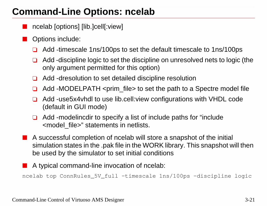
3-21
e to 1ns/100ps
d nets to logic (the
pectre model file
ith VHDL code
“include
of the initialsnapshot will then
iscipline logic
Command-Line Control of Virtuoso AMS Designer
Command-Line Options: ncelab■ ncelab [options] [lib.]cell[:view]
■ Options include:
❏ Add -timescale 1ns/100ps to set the default timescal
❏ Add -discipline logic to set the discipline on unresolveonly argument permitted for this option)
❏ Add -dresolution to set detailed discipline resolution
❏ Add -MODELPATH <prim_file> to set the path to a S
❏ Add -use5x4vhdl to use lib.cell:view configurations w(default in GUI mode)
❏ Add -modelincdir to specify a list of include paths for<model_file>” statements in netlists.
■ A successful completion of ncelab will store a snapshot simulation states in the .pak file in the WORK library. Thisbe used by the simulator to set initial conditions
■ A typical command-line invocation of ncelab:
ncelab top ConnRules_5V_full -timescale 1ns/100ps -d

3-22
Command Line Options: ncelab
dix A), type:
o use whene specified if the
unit for delays (ahe second number,
hematic, module),sub-cell views to the name of the
e logic
celab command.
3/10/05 Virtuoso AMS Designer
■ For a list of additional options (which is also provided in Appen
ncelab -help
■ ConnRules_5V_full tells ncelab which compiled connect rules tinserting connect modules. A connectrules module name must bdesign contains analog and digital elements.
■ The first number in the option -timescale 1ns/100ps sets the timedelay in a module of #10 would become 10ns in this example). T100ps, sets the round-off precision during calculation.
■ In a design where several views exist for some sub-cells (e.g. sca config view of the top cell must exist to let ncelab know whichuse in the elaboration. In a configured design, ncelab is suppliedtop-level config view, e.g.:ncelab amslib.top:config mixedsignal -disciplin
■ The top-level module name must follow immediately after the n
■ To obtain information on an error or warning, use:
nchelp ncelab ERROR_CODE

3-23
u only enable a
l File, e.g., top.scs
op.tcl
top.tcl -gui
Command-Line Control of Virtuoso AMS Designer
Command-Line Options: ncsim■ ncsim [options] [lib].[cell]:[view]
■ Options include:
❏ Add -amslic to enable AMS simulation (otherwise, yodigital simulation)
❏ Add -analogcontrol <file> to use the Simulation Contro
❏ Add -input <file> to call a Tcl control script file, e.g., t
❏ Add -gui to start the SimVision control panelsor
❏ Add -tcl to control ncsim with Tcl commands
❏ Add -profile to get a report of simulator performance
■ A typical command-line invocation of ncsim:
ncsim top -amslic -ANALOGCONTROL top.scs -input

3-24
Command Line Options: ncsim
dix A), type:
hematic, module), sub-cell views tothe name of the
top.scs -gui
3/10/05 Virtuoso AMS Designer
■ For a list of additional options (which is also provided in Appen
ncsim -help
■ In a design where several views exist for some sub-cells (e.g., sca config view of the top cell must exist to let ncsim know whichuse in the simulation. In a configured design, ncsim is supplied top-level config view, as follows:ncsim amslib.top:config -amslic -analogcontrol
■ ANALOGCONTROL can also be lowercase analogcontrol
■ The order of items after the ncsim command does not matter.
■ To obtain information on an error or warning, use:
nchelp ncsim ERROR_CODE
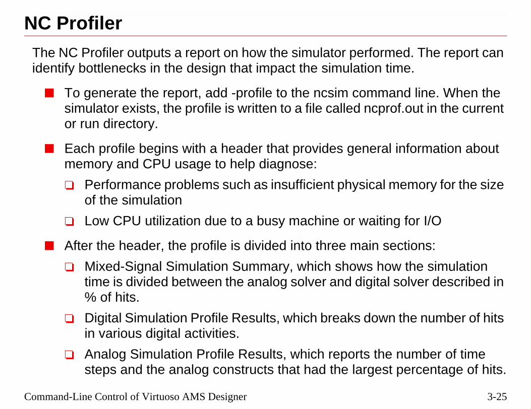
3-25
ed. The report cane.
nd line. When thef.out in the current
information about
emory for the size
g for I/O
ctions:
the simulationsolver described in
the number of hits
number of time percentage of hits.
Command-Line Control of Virtuoso AMS Designer
NC ProfilerThe NC Profiler outputs a report on how the simulator performidentify bottlenecks in the design that impact the simulation tim
■ To generate the report, add -profile to the ncsim commasimulator exists, the profile is written to a file called ncproor run directory.
■ Each profile begins with a header that provides general memory and CPU usage to help diagnose:
❏ Performance problems such as insufficient physical mof the simulation
❏ Low CPU utilization due to a busy machine or waitin
■ After the header, the profile is divided into three main se
❏ Mixed-Signal Simulation Summary, which shows howtime is divided between the analog solver and digital% of hits.
❏ Digital Simulation Profile Results, which breaks downin various digital activities.
❏ Analog Simulation Profile Results, which reports thesteps and the analog constructs that had the largest

3-26
NC Profiler
information about
3/10/05 Virtuoso AMS Designer
Extracted portions of a profile report from the ncprof.out file:
See Appendix D in the Virtuoso AMS Simulator User Guide for morethe profiler.
Memory Usage - 20.5M program + 16.7M data + 1.0M profile = 38.2M totalCPU Usage - 0.4s system + 4.2s user = 4.6s total (14.8% cpu)------------------------------------------------------------Mixed-signal simulation summary (284 hits total)------------------------------------------------------------%hits #hits domain 91.9 261 Analog 8.1 23 Digital------------------------------------------------------------Digital Simulation Profile Results------------------------------------------------------------Stream Counts (23 hits total)------------------------------------------------------------%hits #hits #inst name 52.2 12 [ ] tcl_functions 30.4 7 [ ] outside engine 13.0 3 [ ] Library function minnow (time callbacks) 4.3 1 [ ] ssslib eottracelist for SHM------------------------------------------------------------Analog Simulation Profile Results------------------------------------------------------------------------------- Events and Operators -------------------------------------------------------------------------------%cost #hits type instance 8.1 465 filter top.dac (file: sourcelib/daconv.v line: 40) 6.8 391 cross top.comp (file: sourcelib/comparator.v line: 28) 6.5 375 cross top.comp (file: sourcelib/comparator.v line: 23) 4.1 234 dVar top.comp.offset (file: sourcelib/comparator.v line: 17) 2.0 113 dVar top.dac.b3 (file: sourcelib/daconv.v line: 24) 2.0 113 dVar top.dac.b4 (file: sourcelib/daconv.v line: 24)

3-27
atically calls eachd simulate.
a Verilog top-levelHDL units at
nguages
ulation Control
discipline during
top-level units. Use
Command-Line Control of Virtuoso AMS Designer
NCVerilog■ ncverilog is a single command-line executable that autom
of the three steps of the NC flow: compile, elaborate, an
■ ncverilog can be used with mixed language designs withmodule instead of the using three-step flow, even with Vlower-levels in the design.
❏ Add +ncams to include the AMS license
❏ Add +mixedlang to support both VHDL and Verilog la
❏ Add +gui to invoke SimVision for simulation control
❏ Add +ncanalogcontrol+<filename>.scs to add the SimFile for the Analog Solver.
❏ Add +ncelabargs+”-discipline logic” to add a default elaboration.
■ ncverilog should not be employed in a design with VHDLthe three-step approach instead.

3-28
NCVerilog
of options for
3/10/05 Virtuoso AMS Designer
■ Enter ncverilog -help to get a more complete list and descriptionncverilog.

3-29
wn in the following
/*.v
1ns/100ps
cs -gui
Command-Line Control of Virtuoso AMS Designer
UNIX Scripts for Running AMSA full simulation can be controlled by a UNIX script file, as shoexample:
#!/bin/csh -f
# run ncvlog
echo “running ncvlog”
ncvlog -ams ./sourcelib/*.vams ./connect_lib
ncvhdl -f vhdl_file_list
# run ncelab
echo “running ncelab”
ncelab top_test ConnRules_5V_full -timescale
# run ncsim
echo “running ncsim on snapshot”
ncsim top_test -amslic -ANALOGCONTROL test.s

3-30
UNIX Scripts for Running AMS
everal of the labs.
3/10/05 Virtuoso AMS Designer
■ There are other UNIX scripts to control the simulation flow in sThey can be examined to see other formats and content.
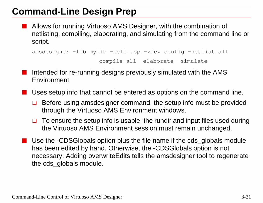
3-31
bination ofe command line or
etlist all
ate
th the AMS
e command line.
must be provided
ut files used during unchanged.
s_globals moduleption is not
tool to regenerate
Command-Line Control of Virtuoso AMS Designer
Command-Line Design Prep■ Allows for running Virtuoso AMS Designer, with the com
netlisting, compiling, elaborating, and simulating from thscript.
amsdesigner -lib mylib -cell top -view config -n
-compile all -elaborate -simul
■ Intended for re-running designs previously simulated wiEnvironment
■ Uses setup info that cannot be entered as options on th
❏ Before using amsdesigner command, the setup info through the Virtuoso AMS Environment windows.
❏ To ensure the setup info is usable, the rundir and inpthe Virtuoso AMS Environment session must remain
■ Use the -CDSGlobals option plus the file name if the cdhas been edited by hand. Otherwise, the -CDSGlobals onecessary. Adding overwriteEdits tells the amsdesignerthe cds_globals module.

3-32
Command Line Design Prep
um characters
the configuration
configuration
e configuration
ileName>..log
load. Default is
fault is none.
efault is none.
-edited
3/10/05 Virtuoso AMS Designer
Options for amsdesigner command (capital letters indicate the minimneeded to recognize the option:
Option Argument to Option Description
-LIb <libname> Specify library name of
-CEll <cellname> Specify cell name of the
-VIew <viewname> Specify view name of th
-LOg <logFileName> Write messages to <logFDefault is ./amsdesigner
-CDSLib <PathtoCDS.LIB> Specify the cds.lib file to./cds.lib
-Netlist incremental | all | none Specify netlist mode. De
-COmpile whenNetlist | all | none Specify compile mode. D
-Elaborate Request elaboration
-Simulate Request simulation
-CDSGloblas overwriteEdits | retainEdits Specify handling of usercds_globals module

3-33
ated by a UNIX
w schematic
tic view of the
ak file using ncvlogon of the
/verilog.vams
mand line, youodule during
top_config ...
Command-Line Control of Virtuoso AMS Designer
Schematic Netlists■ A verilog.vams netlist for a schematic can also be gener
command using the amsdirect netlisting tool:amsdirect -lib workLib -cell comparator -vie
❏ The verilog.vams netlist will be stored in the schemanetlisted cell.
■ The verilog.vams netlist needs to be compiled into the .pwith the -use5x and -view options, followed by the locativerilog.vams file:
ncvlog -ams -use5x -view schematic
./worklib/comparator/schematic
■ To simulate a design that uses schematics from the commust use a configuration and include the cds_globals melaboration:ncelab worklib.top:config worklib.cds_globals:
ncsim worklib.top:config ...

3-34
Schematic Netlists
etlists, need to beg compilation.
3/10/05 Virtuoso AMS Designer
■ Primitive libraries, or components that appear in verilog.vams ncompiled into lib.cell:view format using the -use5x option durin

3-35
d in ADE, with
ances in the netlistormats), ande.g., custom.il:
ance master in thatnent is used.
(fields may beerent netlisting
Proc procedure to.
ge data only, ortions)
Command-Line Control of Virtuoso AMS Designer
Custom NetlistingVerilog-AMS netlists can be customized, similar to that allowevarying levels of complexity to suit the specific need.
■ Add an initFile variable to the ams.env file to affect all inst(header printing, parameter exclusion, various naming fprovide the SKILL file that defines the new procedures,
amsDirect initFile string “custom.il”
■ Add a libInit.il file to a library that applies to a specific instlibrary, which will automatically loaded when the compo
■ Set the new netlist procedure in the CDF simInfo—amsfunctions rather than static data). This would allow a diffprocedure for resistors than capacitors, for example.
❏ Add the instance function that overrides the instancethe master CDF simInfo field called netlistProcedure
■ Load a user-provided procedure through the CIW (chanoverride printing procedures using provided helper func
load(“custom.il”)

3-36
Custom Netlisting
ing Customized
3/10/05 Virtuoso AMS Designer
See the Virtuoso AMS Environment User Guide, Chapter 13, “ProducNetlists,” for more detail on generating customized netlists.

3-37
n one or moreare compiled into.
pshot, which goes
the number of files
nd with the -lib
because they are
e design files withlls left over from aue views to use for
Command-Line Control of Virtuoso AMS Designer
The .pak File■ NC stores output data from ncvlog, ncvhdl, and ncelab i
packed files with the extension .pak in the library the files
■ When the elaborator is done, it writes its output to a snainto the .pak file in the library containing the config.
■ Pak files are used to speed up performance by reducingto open.
■ Examine the contents of a .pak file with the ncls commaoption set to the WORK library:
ncls -lib worklib
■ Pak files must have their permissions set to be writable,updated after each compile and elaboration.
■ It is often helpful to remove .pak files prior to rebuilding thnew views, in case there are other views of the same ceprevious simulation. If the elaborator is not bound to uniqeach cell, it will report a failure to resolve the cell view.

3-38
The .pak File
wo ways:
views to use
> option.
3/10/05 Virtuoso AMS Designer
■ Bindings to unique views for each cell can be accomplished in t
❑ Building a config view, which informs the elaborator which
❑ Binding Verilog cells to views with the ncelab -binding <arg
■ Other commands for use with .pak files are:
❑ ncrm, which will remove an object from the .pak file
❑ ncpack, which will unpack and repack a .pak file

3-39
04 Cadence Design Systemsonnect (VST)
ST)B)T)
G) <0x5937a2b3>D) <0x5937a2b3>M) <0x00000001>B)
0x3c7e09dd> <0x00000001>
9e6dbd1>00000001>
T)D) <0x6ca876f7>
K:VHDL_BEHAVIORAL (AST)K:VHDL_BEHAVIORAL (SIG)
K:VHDL_BEHAVIORAL (COD)
K:VHDL_BEHAVIORAL (COD)
<0x00000001>he CDSINTERNAL analog mod-
ration
Command-Line Control of Virtuoso AMS Designer
.pak File Contents
ncls: 05.30-p001: (c) Copyright 1995-2004 Cadence Design Systemsconnect worklib.ConnRules_3V_basic:connect (VST)connect worklib.ConnRules_3V_full:connect (VST)connect worklib.ConnRules_3V_mid:connect (VST)module worklib.E2L:module (VST)module worklib.L2E:module (VST)module worklib.cds_globals:module (VST)module worklib.comparator:module (VST)module worklib.daconv:module (VST)module worklib.probe:module (VST)module worklib.samplehold:module (VST)module worklib.sareg:module (VST)module worklib.signalSrc:module (VST)module worklib.top:module (VST)entity WORKLIB.VHDL_CLOCK (AST)entity WORKLIB.VHDL_CLOCK (COD) <0x6ca876f7>architecture WORKLIB.VHDL_CLOCK:VHDL_BEHAVIORAL(AST)architecture WORKLIB.VHDL_CLOCK:VHDL_BEHAVIORAL(COD) <0x6ca876f7>
ncls: 05.30-p001: (c) Copyright 1995-20connect worklib.ConnRules_3V_basic:c...module worklib.L2E:module (VST)module worklib.cds_globals:module (Vmodule worklib.cdsinternal:module (SDmodule worklib.comparator:module (VSmodule worklib.comparator:module (SImodule worklib.comparator:module (COmodule worklib.comparator:module (SAmodule worklib.comparator:module (SDmodule worklib.daconv:module (VST)module worklib.daconv:module (SIG) <module worklib.daconv:module (SAM)module worklib.daconv:module (SDB)module worklib.probe:module (VST)...module worklib.top:module (VST)module worklib.top:module (SIG) <0x0module worklib.top:module (SAM) <0xmodule worklib.top:module (SDB)entity WORKLIB.VHDL_CLOCK (ASentity WORKLIB.VHDL_CLOCK (COarchitecture WORKLIB.VHDL_CLOCarchitecture WORKLIB.VHDL_CLOC<0x37d147d7>architecture WORKLIB.VHDL_CLOC<0x37d147d7>architecture WORKLIB.VHDL_CLOC<0x6ca876f7>module worklib.vsource:module (SAM)module worklib.worklib_top_module_Tule:module (SAM) <0x00000001>snapshot worklib.top:module (SSS)
After Compilation After Elabo

3-40
Pak File Objects
3/10/05 Virtuoso AMS Designer
■ Objects in the .pak file are given in the format:design_unit_type lib.cell[:view] (object type)
■ The design unit types include:
❑ Verilog modules and primitives
❑ VHDL entities and architectures
❑ Simulation Snapshots
■ The object types include:
❑ Verilog Syntax Tree (VST)
❑ VHDL Syntax Tree (AST)
❑ Overlay Tables (SIG)
❑ Code (COD)
❑ Simulation Snapshot (SSS)
■ VST and AST objects are the result of compilation.
■ COD and SSS objects are the result of elaboration.

3-41
ulation control can for example:
Command-Line Control of Virtuoso AMS Designer
Tcl Commands■ Once ncsim starts (as shown by the ncsim> prompt), sim
be done interactively through the use of Tcl commands,
ncsim> run 100 us
■ Useful Tcl commands for AMS include:
describe finish
force help
probe release
reset run
save scope
status stop
time value
where restart
deposit

3-42
Tcl Commands
,” which is agrams.
tabase)
ab -access +r+w
“Tcl-Based
3/10/05 Virtuoso AMS Designer
■ Tcl (pronounced “tickle”) stands for “Tool Command Languagescripting language used for issuing commands to interactive pro
■ Tcl commands can:
❑ Control an SHM (Simulation History Manager) database (da
❑ Display information about a simulation object (describe)
❑ Force a digital object to a value and maintain value (force)
❑ Display information about a command (help)
❑ Control digital signals to be probed for a database (probe)
❑ Release a forced value on an object (release)
❑ Step and trace through a simulation (run)
❑ Traverse the model hierarchy (scope)
❑ Manipulate breakpoints of many types (stop)
❑ Observe signal values (strobe, value)
❑ Save values at a checkpoint (save)
❑ Restart a simulation from a saved checkpoint (restart)
■ The Tcl commands, deposit, force, and release, require the nceloption to be set.
■ Refer to the Virtuoso AMS Simulator User Guide, Appendix B, Debugging,” for more information on Tcl commands.

3-43
ommand, and can
gn Browser
l Verilog-AMS
l VHDL-AMS
ot affected
Command-Line Control of Virtuoso AMS Designer
TCL Current Probes■ Probing currents in and out of ports uses a TCL probe c
be used to probe either all ports or an individual port.
Results will show up as <port_name_$flow> in the Desi
■ Currently supported:
❏ Probing at electrical ports of structural and behavioramodels
❏ Probing at terminal ports of structural and behavioramodels
❏ Probing currents at primitive terminals
■ No current probe devices are inserted, so the netlist is n
■ Examples:
probe -create -flow -shm -ports top.A
probe -create -flow -shm -ports top.C1.PLUS

3-44
TCL Current Probes
3/10/05 Virtuoso AMS Designer

3-45
file called whening example:
Command-Line Control of Virtuoso AMS Designer
Tcl Scripts■ A sequence of Tcl commands can be placed in a script
ncsim is invoked using the -input option, as in the follow
ncsim top -amslic -input top.tcl
■ A typical Tcl script file:
set display_unit NS
alias tp run -timepoint
alias . run
alias quit exit
database -open waves -into tran1.tran -default
probe -create -shm top -all -depth all
scope -set top
stop -time 856 -absolute

3-46
Tcl Scripts
ase has not beenmatically.
3/10/05 Virtuoso AMS Designer
■ The example above shows several possible uses of a Tcl script.
❑ Set some parameters
❑ Set some aliases for this run
❑ Save some waveforms
❑ Set the scope
❑ Set a breakpoint
■ If the probe command is used with the -shm option, and a databdefined, then a default database, ncsim.shm, will be opened auto

3-47
ved, and restartedand “restart” at the
.
s
point, and then
file at t=t1.
Command-Line Control of Virtuoso AMS Designer
Simulation Save/Restart■ The simulation can be stopped, the state of all signals sa
at a later time from an ncsim> prompt using the Tcl commfollowing simulation states:
❏ At the first Tcl prompt
❏ After running a simulation for a certain period of time
❏ During debug of digital-HDL/AMS code.
❏ At any sync point during the execution of delta-cycle
■ Simple usage: run a simulation up to t=t1, save a checkrestart.
❏ A checkpoint is saved as a new snapshot in the .pak

3-48
Simulation Save/Restart
3/10/05 Virtuoso AMS Designer

3-49
sited, the probesntrol options
tions for recovery
same operating stopped.
can be simulateds the starting pointent.
Command-Line Control of Virtuoso AMS Designer
Applications for Save/Restart■ Before restarting, new digital signal values can be depo
(signals to be displayed) changed, and some analog cochanged.
■ Automatic checkpoints can be saved during long simulafrom network failures or power outages.
■ Simulations can be moved to other workstations with thesystem and restarted from the point the first workstation
■ Start-up phases, such as power-on resets or oscillators,once, the states saved, and then the saved states used ain multiple simulations where the digital stimuli are differ

3-50
Applications for Save/Restart
3/10/05 Virtuoso AMS Designer

3-51
pshot
the probes
:chkpt
-amslic -gui
Command-Line Control of Virtuoso AMS Designer
Save/Restart Usage■ To save the simulation state from an ncsim> prompt:
ncsim> run -sync
ncsim> run -clean
ncsim> save worklib.top:chkpt1 //saves a new sna
ncsim> save -environment checkpoint1.tcl //saves
■ To restart the simulation from an ncsim> prompt:
ncsim> restart worklib.top:chkpt1
■ To save a checkpoint every 10ns of simulation time:
ncsim> stop -time 10ns -relative -execute {save
-overwrite}; run
■ To restart a simulation from the UNIX command line:
ncsim worklib.top:chkpt1 -analogcontrol top.scs
-input checkpoint1.tcl

3-52
Save/Restart Usage
imulation—Save
before depositing
eckpoint can be
for later use.
ed as the argument
view, letting the
t a save command
3/10/05 Virtuoso AMS Designer
■ From SimVision, the Save/Restart commands are found under SCheckpoint/Restart from Checkpoint.
❑ Do a run -sync to synchronize the analog and digital solvers digital signal values.
❑ Do a run -clean to advance to the next point from which a chsaved.
❑ Do a save -environment <checkpoint1>.tcl to save probe sets
❑ restart -show will list the names of all snapshots that can be usto the restart command.
■ Snapshot names can be full, lib.cell:view, or partial with just thesimulator add the current lib and cell.
■ Control-C will stop the simulator from an ncsim> prompt so thacan be issued at any arbitrary time.

3-53
gital Valuesed at any stage ofbstol, iabstol, and
to the snapshot,
value after a save:
bstol, reltol, and
arameters
Command-Line Control of Virtuoso AMS Designer
Use S/R to Change Spectre Controls or Di■ The following Spectre control parameters can be chang
the simulation using the Tcl “analog” command: reltol, vastop time:
ncsim> analog -reltol 0.001
ncsim> analog -vabstol 1m
ncsim> analog -stop 100us
■ Modified values of the analog parameters will be writtenand reloaded the next time the snapshot is loaded.
■ To change the value of a digital control bus deposit a bus
ncsim> deposit r[0:7] = 8’h1F
■ Information commands:
❏ analog -show will list the current values of vabstol, iastop time.
❏ analog -help will give more information about these p

3-54
Using S/R to Change Analog Parameters
3/10/05 Virtuoso AMS Designer

3-55
during a simulation
e restarted from
e restarted fromal value.)
Command-Line Control of Virtuoso AMS Designer
A Sample S/R SessionThe following example shows how Save/Restart can be usedsession.
ncsim> run 100 ns (reltol = .001)
ncsim> run -clean
ncsim> save worklib.top:chkpt1
ncsim> analog -reltol 0.002
ncsim> run -sync
ncsim> deposit b0 = 1’b1
ncsim> run 200 ns
ncsim> run -clean
ncsim> save worklib.top:chkpt2
ncsim> analog -reltol 0.005
ncsim> run 100 ns
ncsim> restart worklib.top:chkpt2 (Simulation will btime=300ns with reltol = 0.002.)
ncsim> run 100 ns
ncsim> restart worklib.top:chkpt1 (Simulation will btime=100ns with reltol = 0.001, and b0 at its initi

3-56
A Sample S/R Session
be added to the
3/10/05 Virtuoso AMS Designer
The Tcl “deposit” command requires the option -access +r+w toncelab command.

3-57
ulation?
Command-Line Control of Virtuoso AMS Designer
Review1. What’s the three command sequence used to run a sim
2. What are the required files and directories?
3. What determines the use of a configuration?
4. Which Tcl command will save the waveforms?
5. Which Tcl command saves the simulation states?

3-58
Review
s which one to use
3/10/05 Virtuoso AMS Designer
1. The three command sequence to run a simulation are:ncvlog -ams (ncvhdl -ams)
ncelab
ncsim -amslic
2. cds.lib, hdl.var, filename.scs, ./worklib, source files
3. The existence of multiple views of a cell, so the elaborator know
4. probe -create -shm top-file-name
5. save <snapshot_name>

3-59
ine
Command-Line Control of Virtuoso AMS Designer
Labs
Lab 3-1 Command-Line Control of Virtuoso AMS Designer
Lab 3-2 Working with Configurations from the Command L
Lab 3-3 Mixing VHDL and Verilog (Optional)

3-60
3/10/05 Virtuoso AMS Designer
®
March 10, 2005
Module 4
4 Virtuoso A ner in ADE
MS Desig
4-2
3/10/05 Virtuoso AMS Designer
4-3
Virtuoso AMS Designer in ADETopics in this Module■ Typical AMS in ADE simulation flow
■ Required files
■ WaveScan display

4-4
3/10/05 Virtuoso AMS Designer
4-5
simulation.
matic at top level
background
s
n halts
and digital signals
veform files in sst2
Virtuoso AMS Designer in ADE
AMS in ADEUses Virtuoso® Analog Design Environment to control an AMS
■ Starts with 5.X directory structure with a configured sche
■ Compiling, elaborating, and simulating steps done in the
■ Selection from pre-compiled Connect Rules and Module
■ AC simulations can be launched after transient simulatio
■ WaveScan is the default waveform viewer for both analog(psf format)
■ SimVision is available for displaying existing transient waformat

4-6
3/10/05 Virtuoso AMS Designer
4-7
Virtuoso AMS Designer in ADEFiles Required for AMS in ADE■ Files required for AMS in ADE:
❏ cds.lib (list of libraries for the design)
❏ design in 5.X library structure
❏ pre-compiled Connect Modules and Rules
■ Not needed:
❏ hdl.var
❏ work library
■ Optional:
❏ .cdsinit (bindkey and other configuration info)
❏ .cdsenv (environment variables)
❏ .artist_states (settings for ADE form)
■ Output files:
❏ /simulation directory containing:❍ Netlist and pak files❍ psf output files

4-8
3/10/05 Virtuoso AMS Designer
4-9
Virtuoso AMS Designer in ADEStarting AMS in ADEBasic steps to starting AMS in ADE:
1. Start the icms executable (or icfb).
2. Open a configured schematic (or create one).
3. Start ADE (Tools—Analog Environment)

4-10
3/10/05 Virtuoso AMS Designer
4-11
Virtuoso AMS Designer in ADESetting Up AMS in ADEOnce ADE is open, the next steps are toset up the simulation run:
1. Set the simulator to ams (Setup—Simulator/Directory/Hosts)
2. Set model path (Setup—ModelLibraries)
3. Choose Connect Rules(Setup—Connect Rules)
Simulator
Models
Connect Rules

4-12
sinit file:ms”)
3/10/05 Virtuoso AMS Designer
To set the simulator default to “ams” add the following line to the .cdenvSetVal(“asimenv.startup” “simulator” ‘string “a

4-13
the built-in sett.
prior to running a
fined
te the in the Library
were compiled.
Virtuoso AMS Designer in ADE
Choosing Connect RulesConnect Rules to be used during simulation are chosen from provided in the software installation, or from a user-defined se
■ Connect Rules and Connect Modules must be compiledsimulation.
Built-in User-de
Browse to locaConnect Rulesto which they
Select theBuilt-in ConnectRule set.
OR

4-14
3/10/05 Virtuoso AMS Designer
4-15
tions as necessary
Select on
d in:
etlist/ihnl directory;
itten to:
etlist ande netlists
Virtuoso AMS Designer in ADE
Setting Up the Simulation in AMS in ADE1. Choose analyses (Tran, AC, DC) and set values and op
(see following slides).
2. Choose outputs for display (Outputs—To Be Plotted—Schematic)
3. Create the netlist (Simulation—Netlist—Create)
❏ The design netlists and netlister.log file will be create/simulation/<designname>/ams/config/netlist
❏ The netlists and HDL files will be compiled into the nand an ncvlog.log file will be created in the directory:/simulation/<designname>/ams/config/psf
4. Run (Simulation—Run)
❏ Output files, ncelab.log and ncsim.log files will be wr/simulation/<designname>/ams/config/psf
Note: Executing Simulation—Netlist and Run or clicking on the NRun icon will incrementally netlist the schematics, compile thand HDL files, elaborate the design and run the simulation.

4-16
Save State) andADE can use state
nals. AC currents
lly, whileot exist previously.
ptions menu, andonment Reference
eon run.
3/10/05 Virtuoso AMS Designer
■ Settings in the ADE form can be saved to a state file (Session—loaded from a previous session (Session—Load State). AMS infiles created by any other simulator.
■ Use the ADE Output menu to save all signals or just specific sigcannot be saved at the present time.
■ Simulation—Netlist—Create will create the netlist incrementaSimulation—Netlist—Recreate creates the netlist as if it did n
■ Other simulation options are available from the Simulation—Othey are explained at the end of Module 14 Virtuoso AMS Envir(Optional).
■ To re-run the simulation using the SimVision Debugger, executSimulation—SimVision Debugger after completing a simulati

4-17
lysis form, you can
other optionsecessary.
Virtuoso AMS Designer in ADE
Transient Simulation OptionsAfter you set the stop time and errpreset in the main tran anasee other options by clicking on the Options button.
Set the Stop timeand errpreset (defaultis moderate).
Setas n

4-18
ntrol.scs file aftertion completes.
ints to be saved at
to the schematic
er 12 for more
3/10/05 Virtuoso AMS Designer
Enabling a transient analysis will add a finalTimeOP card to the amsCothe tran card, which will save the DC operating points after the simula
Setting infotimes in the Transient Options form will cause operating pospecific intervals.
Analog node voltages at specific time settings can be back-annotated (Results—Annotate—Transient Node Voltages).
Refer to the Virtuoso Analog Design Environment User Guide, Chaptinformation on the other transient simulation options.

4-19
node voltages for
o therd) so that the DC
Virtuoso AMS Designer in ADE
AMS in ADE DC SimulationSetting the DC Operating Point allows back-annotating the DCanalog signals to the schematic.
Enabling Save DC Operating Point will add a dcOpinfo card tamsControl.scs file in the /netlist directory (before the tran cainfo is measured before the transient simulation.

4-20
3/10/05 Virtuoso AMS Designer
4-21
ting points
et the digital signal
only
tions
Virtuoso AMS Designer in ADE
AC Simulation Options■ AC simulation can be performed:
❏ After a transient simulation using the final tran opera
❏ Standalone using initial DC operating points which slevels
❏ Doing frequency sweeps only
■ AC sweep results can be viewed in WaveScan or AWD
Set startand stopfrequenciesand steps
Op
AC Sweep

4-22
3/10/05 Virtuoso AMS Designer
4-23
art automatically
Virtuoso AMS Designer in ADE
WaveScan Waveform DisplayWaveScan is the default waveform viewer for ADE and will stwhen the simulation completes.
Use the Strip Chart Mode icon toseparate overlayed analog traces.
Digital on top
Overlayedanalogtraces

4-24
e .cdsinit file:)
e following line to
ogStrip”)
xecutethe database fileer.
3/10/05 Virtuoso AMS Designer
■ To use AWD instead of WaveScan, add the following line to thenvSetVal(“asimenv.startup” “cds_ade_wftool” ‘string “awd”
■ To set the waveform traces to be in strip mode by default, add ththe .cdsinit file:
envSetVal(“asimenv.plotting” “stripModeType” ‘cyclic “anal
■ To plot the waveforms using the SimVision waveform viewer, eTools—SimVision Waves after the simulation completes, open psf.trn, and select the signals of interest from the Design Brows

4-25
Virtuoso AMS Designer in ADELabs
Lab 4-1 Using AMS in ADE
Lab 4-2 AC Analysis with AMS in ADE
Lab 4-3 Parasitic Simulation in AMS
Lab 4-4 Running the SAR A2D in ADE (Optional)

4-26
3/10/05 Virtuoso AMS Designer
®
March 10, 2005
Module 5
5 Virtuoso A ner in VSDE
MS Desig
5-2
3/10/05 Virtuoso AMS Designer
5-3
SDE) for
Virtuoso AMS Designer in VSDE
Topics in this Module■ Using the Virtuoso® Specification-driven Environment (V
automating corners simulation using AMS
■ Typical AMS in VSDE simulation flow

5-4
3/10/05 Virtuoso AMS Designer
5-5
up multiples (extreme values
other, or against
from the command
AMS Designer.
Virtuoso AMS Designer in VSDE
AMS in VSDE■ VSDE (Virtuoso Specification-driven Environment) sets
simulations to characterize a circuit over multiple cornerof process, voltage, temperature, or other variables).
■ The results of each simulation can be compared to eachspecification limits, to analyze production yield issues
■ VSDE can be started from a schematic, from the CIW, orline.
■ VSDE can use a variety of simulators, including Virtuoso

5-6
3/10/05 Virtuoso AMS Designer
5-7
r command line.
r choice and the ADE (if desired).
AMS as theulator
port State filem ADE (if desired)
Virtuoso AMS Designer in VSDE
Setting Up a VSDE AMS Project1. Start VSDE from the Virtuoso Schematic Editor, CIW, o
2. Create a VSDE workspace and project.
3. Create a test for the project, using AMS as the simulatoconfig view of the design, and importing a state file from
SetSim
Imfro
Set ConfiguredDesign
Name of Test

5-8
3/10/05 Virtuoso AMS Designer
5-9
e, $vdd,
rt them from
e theurement CalculatorEAN script)
Virtuoso AMS Designer in VSDE
Creating Test Measures1. Add project parameters (variables, such as $temperatur
$process_dir, $corner)
2. Define measures for the test (e.g., gain, delay), or impoprevious projects.
MeasurementName
Definmeas(ADEor OC

5-10
3/10/05 Virtuoso AMS Designer
5-11
ameters (usuallyperature limits).
on any page).
ers to belated
Virtuoso AMS Designer in VSDE
Defining the Corners to Be Simulated1. Set up the corners to be simulated using the project par
combinations of process speed, supply voltage and tem
2. Start the simulation runs by clicking on the Run button (
Cornsimu
Tests tobe run
Run

5-12
3/10/05 Virtuoso AMS Designer
5-13
mat, plotted in
Virtuoso AMS Designer in VSDE
Viewing ResultsResults of the simulation runs can be compared in a chart forwaveform displays, and compared against a specification.
Compare raw test results in a chart format:
Compare results against a specification:

5-14
ch corner test and
3/10/05 Virtuoso AMS Designer
The specification sheet can be expanded to summarize the results of eaindicate pass/fail against the limits:

5-15
Virtuoso AMS Designer in VSDECompare Results in a Waveform DisplayView results as waveforms:

5-16
3/10/05 Virtuoso AMS Designer
5-17
Virtuoso AMS Designer in VSDELabs
Lab 5-1 Using AMS in VSDE

5-18
3/10/05 Virtuoso AMS Designer
®
March 10, 2005
Module 6
6 Analog So tre, and SPICE
lver, Spec
6-2
3/10/05 Virtuoso AMS Designer
6-3
Analog Solver, Spectre, and SPICETopics in this Module■ The Analog Solver in AMS
■ Simulation Control File structure
■ Instantiating analog primitives
■ Analog Model Form
■ SPICE and Spectre® models and subcircuits
■ Verilog-A Table Models

6-4
Analog Solver, Spectre, and SPICE
3/10/05 Virtuoso AMS Designer
■ “Solver” means the same as “simulation engine.”

6-5
as Spectre
e digital solver
oach
log solver
Analog Solver, Spectre, and SPICE
Analog Solver■ AMS uses the same solver as Spectre standalone
❏ Built from the same source code
❏ Supports the same device models and components
❏ Supports transient analysis in synchronization with th
■ Simulation control currently uses a dual control file appr
❏ Spectre control file (ANALOGCONTROL) for the ana
❏ NC controls (Tcl) for the digital solver

6-6
Analog Solver
3/10/05 Virtuoso AMS Designer
■ Support for SpectreHDL, the precursor to Verilog-A, is limited.

6-7
(Spectre Control
models
ption
y)
itions)
t=sst2 temp=50 C
Analog Solver, Spectre, and SPICE
Refresher on Simulation Control Files■ Typical extension for the Simulation Control File is .scs
Syntax)
■ Contains only Spectre control statements, no netlists or
■ Called during simulation with the ncsim -analogcontrol o
■ Structure of the Simulation Control File:
❏ Language mode (Spectre is default)
❏ Transient Analysis statement (stop time and accurac
❏ Simulator Option statements (e.g., reltol)
❏ Simulator Control statements (Save and Initial Cond
■ A typical Simulation Control File:
simulator lang=spectre
amsAnalysis tran stop=100u errpreset=moderate
analogOptions options reltol=.005 save=selected rawfm
save top.I2.M6:all
ic top.I2.vref1=1.035

6-8
Refresher on Simulation Control Files
he Virtuoso AMSircuit Simulator
t under Options.
servative option
he default for
can format. Thesfbinf for compact
3/10/05 Virtuoso AMS Designer
■ More detail on Simulation Control File contents is provided in tSimulator User Guide, Chapter 9, and in the Virtuoso Spectre CUser Guide, Chapter 8.
■ Control statements can also be set within the AMS Environmen
■ errpreset can be liberal, moderate, or conservative, with the conbeing most accurate, but consuming more simulation time.
■ Setting a specific reltol value will override that set by errpreset.
■ If save=selected, then the signals to be saved need to be listed. TSpectre is to save all signals.
■ sst2 means to save the waveform data in SimVision and WaveSother choice for the data output format is psfbin for AWD, and ppsf format.
■ Other files with the .scs extension include Spectre model files.

6-9
itives (such as
al
vioral expressions,
have actual ports
d ports. These can into designs.
Analog Solver, Spectre, and SPICE
AMS Instantiation of Primitives■ Analog primitives:
❏ AMS uses string properties like “type” in Spectre primvsource #(.type(“sine”)...)
❏ Defparam of analog primitives is not supported
❏ Analog primitives have a default discipline of electric
❏ User-defined functions (UDFs) are supported in behanot structural
■ Digital primitives:
❏ Cannot be directly connected to an analog primitive.
❏ Cannot be assigned a discipline, because they don’t
❏ Need to have a wrapper around digital primitives to adbe seen in the sample library, which can be compiled

6-10
AMS Instantiation of Primitives
3/10/05 Virtuoso AMS Designer
■ Within AMS, analog subcircuits:
❑ provide SimVision access only at ports
❑ have waveform access to all nodes and devices
■ An example of a wrapper to add pins to a digital primitive:
module nand2 (Y,A,B);
output Y;
input A;
input B;
nand i0 (Y,A,B); // nand is a digital primitive
endmodule

6-11
tor, capacitor,onent.
voltage or currente expression and
Analog Solver, Spectre, and SPICE
Bsource Support■ Behavioral Source (Bsource) allows modeling of a resis
inductor, voltage or current source as a behavioral comp
■ Ability to express the value of a resistance, capacitance,as a combination of node voltages, branch currents, timbuilt-in Spectre expressions.
■ Examples:
❏ Non-linear resistance model
res (n1 n2) bsource r=100*(1+(1/2)+v(n1,n2))
❏ Cap charge model
cap (n1 n2) bsource q=1.0e-6*v(n1,n2)

6-12
Bsource Support
3/10/05 Virtuoso AMS Designer

6-13
at a time can bee is placed in
ar file, as shown
0.15U ld = 0.20U
0.05U ld = 0.20U
ld=0.325U u0=680
0.05U ld = 0.075U
Analog Solver, Spectre, and SPICE
Declaring Model Files with Sections■ Example of a model file with sections:
■ For model files with sections, only one section or cornerused during elaboration and simulation. The section namparentheses in the MODELPATH statement in the hdl.vhere:
define MODELPATH cornerMos.scs(FNSP):rccir.cir
library special_2usection TNTPsimulator lang=spice* Level=2 nominal model.model nmos24 nmos level=2 vto = 0.775 tox = 400e-10 nsub = 8e+15 xj =u0 = 650 ucrit = 0.62e+5 ...
.model pmos24 pmos level=2 vto = -0.75 tox = 400e-10 nsub = 6e+15 xj =u0 = 255 ucrit = 0.86e+5 ...endsection
section FNSPsimulator lang=spice* Level=2 fastN/slowP model.model nmos24 nmos level=2 vto=0.65 tox=370e-10 nsub=6.0e+15 xj=0.15Uucrit=0.62e5 ...
.model pmos24 pmos level=2 vto = -0.9 tox = 430e-10 nsub = 6.6e+15 xj =u0 = 240 ucrit = 0.86e5 ...endsection
endlibrary

6-14
Declaring Model Files with Sections
running from ther in Cadence®
t in the Analog
nstead of in the placed in quoted
cir.cir
3/10/05 Virtuoso AMS Designer
■ Placing the model path in the hdl.var file is only necessary whencommand line. When you are running from the Hierarchy EditoDesign Framework II, the model file path and corner may be seModel Form instead.
■ MODELPATH may be used as an option in the command line ihdl.var file, but must be included for ncelab. Section names areparentheses, as follows:
ncelab <top_module> -MODELPATH cornerMos.scs”(FNSP)”:rc

6-15
dl.var File the names of all
n belowmmon directory):
directory, includeto separate them,
rccir.cir
e globals aree with globals
e line becomes tooue on the next line:
P): \
tions, such ase MODELPATH
(HIGH)
Analog Solver, Spectre, and SPICE
Declaring Models and Subcircuits in the h■ The MODELPATH variable in the hdl.var file is assigned
the SPICE and Spectre circuit and model files, as show(MODELINCDIR may be used to prepend a path to a co
define MODELINCDIR ~/AMSDesigner/ams_anatextlab
define MODELPATH rccir.cir
■ If there are multiple model or subcircuit files in the samethem all on one MODELPATH variable line using a colonas in:
define MODELPATH spectre_prim.scs:powertran.scs:
❏ In the MODELPATH list of files, if there is a file wherdeclared, it must come first, and it can be the only ondeclared. No space is allowed after the colon. But if thlong, you can add a space plus a backslash to contin
define MODELPATH globals.cir:cornerMos.scs(SNScomparator.cir
■ If you have a model file with multiple components in secmosfets and resistors, add each section to be used to thline, repeating the same model file name, for example:
define MODELPATH myModels.scs(SNFP):myModels.scs

6-16
Declaring Models and Subcircuits in hdl.var
ar file.
ditor), models and path, or use theay also be used to
var file.
MODELINCDIR
/bjtmodels
ircuit by using the
3/10/05 Virtuoso AMS Designer
■ You must re-elaborate after changing model corners in the hdl.v
■ For use within the AMS Environment (DFII and the Hierarchy Esubcircuits referenced by MODELPATH must include their fullMODELINCDIR full path definition. The Analog Model Form mset the paths instead of the MODELPATH statement in the hdl.
■ Several directories containing models can be referenced with a definition using a colon (:) to separate them.
define MODELINCDIR ~/myProject/mosmodels:~/myProject
■ Model or subcircuit files cannot include:
❑ Binary or ternary operators
❑ Spectre HDL or structural Verilog-A instances
■ Behavioral Verilog-A models may be included in a Spectre subcahdl_include statement as follows:ahdl_include "VerilogAfile.va"

6-17
c., are used
etlist as defined in the hdl.var
an npn transistor,
ansistor as follows:
50
Analog Solver, Spectre, and SPICE
Instantiating SPICE/Spectre Models■ Some Analog primitives, such as bsim3, npn, mos3, et
indirectly via model files.
❏ The name of the model is used in the Verilog-AMS nthe model file, and the model file must be included inMODELPATH statement.
■ For example:
❏ If the model file contains the following statement for
❏ Then the Verilog-AMS module would instantiate the tr
.MODEL VERTNPN NPN BF=80 IS=1E-18 RB=100 VAF=+ CJE=3PF CJC=2PF CJS=2PF TF=0.3NS TR=6NS
module diffPair (c1, b1, e, b2, c2);electrical c1, b1, e, b2, c2;vertNPN Q1(c1,b1,e);vertNPN Q2(c2,b2,e);
endmodule
6-18
Instantiating SPICE/Spectre Models
e.g., nmos, npn.o calculate itstions used, and thes.
MODELPATHfor DFII use.
.
3/10/05 Virtuoso AMS Designer
■ An analog primitive is a device at its lowest level for netlisting,Each primitive must have a model that tells the simulator how tperformance. The model type (BSIM3v3) defines the set of equamodel file includes values for the coefficients in those equation
■ The model file (and section) must be included in the hdl.var filestatement for command-line use, or in the Analog Model Form
■ Note that the model names and references are not case sensitive

6-19
in the HierarchyAnalog Models
on the Analoga check mark.
de Directories tab.
rence in hdl.var, orodel files.
Analog Solver, Spectre, and SPICE
Analog Model FormThe Analog Model Form can be invoked from the AMS menuEditor, selecting Analog Models, or from the Run Simulation—Setup form.
■ Multiple sections from the same model file can be addedModels tab, as long as only one section is enabled with
■ Relative directory path can be added on the Model Inclu
■ Settings here will override any MODELPATH model refecan be used instead of a MODELPATH statement for m
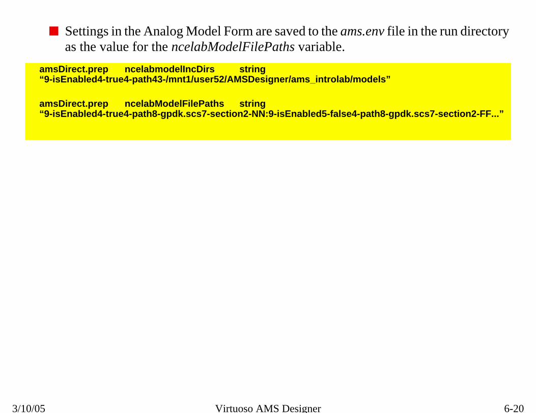
6-20
Analog Model Form
n the run directory
.scs7-section2-FF...”
3/10/05 Virtuoso AMS Designer
■ Settings in the Analog Model Form are saved to the ams.env file ias the value for the ncelabModelFilePaths variable.
amsDirect.prep ncelabmodelIncDirs string“9-isEnabled4-true4-path43-/mnt1/user52/AMSDesigner/ams_introlab/models”
amsDirect.prep ncelabModelFilePaths string“9-isEnabled4-true4-path8-gpdk.scs7-section2-NN:9-isEnabled5-false4-path8-gpdk

6-21
can provide 2X to design.
pectre modelsmine the voltageep.
nd Table modelslver form or as an
Analog Solver, Spectre, and SPICE
MOS Table ModelTable look-up models for Spectre BSIM3, BSIM4 MOS devices3X speed improvements with large numbers of mosfets in the
■ The simulator will calculate the tables from the SPICE/Sbefore beginning the simulation and interpolate to deterand current operating points for mosfets at each time st
■ Switch between full Spectre/SPICE models (Standard) a(accelerated) in AMS—Options—Simulator—Analog Sooptions parameter in the analog control file.

6-22
MOS Table Model
accurate setting is
rain and sourcedefault of 0.0 will
e of Table Models:
andard)
default = 0.05)
3/10/05 Virtuoso AMS Designer
■ The default grid size for MOS Table Models is 0.05, but a more0.025, with the tradeoff of less simulation time improvement.
■ The Node reduction threshold sets a cutoff value for including dresistances in the simulation. Setting the threshold higher than theresult in faster simulation time.
■ In the Analog Control File, the following options control the us
mos_method = a|s (accelerated Table Model or St
mos_vres = <value> (grid size for the Table Model,

6-23
ined tables.
mple:
ith x/y pairs. Whention of f(x) by
rpolation and
d for thelt).
its: C = Clamp,
“3CL, 3CL”)
Analog Solver, Spectre, and SPICE
Verilog-A Table ModelsVerilog-A table models allow the user to import externally def
■ Allows simulation based on x vs. y curves, or a dataset
■ Can provide IP protection for proprietary models, for exa
■ Table models act like a function y = f(x) using a data file wthe $table_model task is called, it returns an approximainterpolation between datapoints.
■ The control strings, e.g., “3CL, 3CL”, determine the inteextrapolation methods:
❏ The number indicates the degrees of the splines useinterpolation between data points, from 1 to 3 (defau
❏ The letters control the extrapolation past the table limL = Linear (default), S = Spline, E = Error
module mynmos (g, d, s);electrical g, d, s;inout g, d, s;
analog beginI(d,s) <+ $table_model (V(g,s), V(d,s), “nmos.tbl”,
endendmodule

6-24
Verilog-A Table Models
e point is beyond
es through thedel evaluation.
gh a tangent line at
arest segment (the area.
apolation method.e interpolation
x
Linear
Clamp
Spline
3/10/05 Virtuoso AMS Designer
The extrapolation method controls how the point is evaluated when ththe region of the user-provided sample points.
■ The Clamp extrapolation method uses a horizontal line that passnearest sample point (also called the end point) to extend the mo
■ The Linear extrapolation method models the extrapolation throuthe end point.
■ The Spline extrapolation method uses the polynomial for the nesegment at the end) to evaluate a point beyond the interpolation
■ The user can also disable extrapolation by choosing the Error extrIn this case, when the system tries to evaluate a point beyond thregion, the system will terminate.
y

6-25
within the
, .fall(10n),
(IN OUT GND)
Analog Solver, Spectre, and SPICE
Instantiating SPICE/Spectre Subcircuits■ SPICE or Spectre subcircuits are instantiated, by name,
Verilog-AMS module.
100Kohm
brcsuba
gnd
vin
//top.vams`include “disciplines.vams”module top;electrical a, b, gnd;ground gnd;
vsource #(.type(“pulse”), .val0(0), .val1(5), .rise(10n).period(100u), .width(50u)) vin (a, gnd);
resistor #(.r(100k)) rout (b, gnd);rcsub rcsub1(a,b,gnd);
endmodule
*rccir.cir.SUBCKT RCSUB R1 IN OUT 5kC1 OUT GND 10N.ENDS RCSUB

6-26
Instantiating SPICE/Spectre Subcircuits
odel with
a similar fashion.
ile MODELPATH
3/10/05 Virtuoso AMS Designer
■ Note how the pulse source is instantiated as a vsource Spectre mpass-down parameters, an instance name, and port names.
■ The termination resistor is instantiated the same way.
■ RCSUB is a SPICE model of an RC filter and is instantiated in
■ The subcircuit file name, rccir.cir, must be added to the hdl.var fstatement.

6-27
vdd! and gnd!)rcuits (such as vddthe Spectre
ctre circuit file:
ith the top-leveluit file duringiles.
dels.scs
Analog Solver, Spectre, and SPICE
Using Globals in a SubcircuitAMS Designer can supply the global supply signals (such as needed to connect to globals used in SPICE or Spectre subciand gnd) by declaring them as globals for both the AMS and simulators.
■ Declare the AMS global signals in a cds_globals file:
module cds_globals ();
electrical \vdd! , \gnd! ;
ground \gnd! ;
endmodule
■ Declare the Spectre global signals in a stand-alone Spe
simulator lang=spectre
global gnd vdd
■ Compile and elaborate the cds_globals module along wcircuit file, and include the modelpath to the Spectre circelaboration along with any other netlist files and model f
ncvlog -ams top.vams cds_globals.vams
ncelab top cds_globals -modelpath globals.cir:mo

6-28
file automatically.
nvenient to do soe Spectre globals
ch the signals are
3/10/05 Virtuoso AMS Designer
■ Design Prep in the Hierarchy Editor will create the cds_globals
■ Spectre globals can only be declared once in a design, so it is coin a stand-alone circuit file that is included in the modelpath. Thfile must come first in the modelpath list, before any file in whiused.

6-29
ls, nets, subcircuitllowed.
d instance name;
Analog Solver, Spectre, and SPICE
Spectre Netlists■ Forward referencing of a hierarchical node is allowed:
simulator lang = spectre
c1 xa.mid 0 capacitor c=0.2p
xa 1 2 buffer
........
■ Multiple namespaces for Spectre device instances, modeparameters and netlist parameters as expressions are a
❏ In the following example, res is both a parameter anc10 is a node, instance, and parameter name:
simulator lang=spectre
parameters c1=1p c2=2p c10=c1+c2
parameters res=10k
res c10 0 resistor r=res
c10 c10 0 capacitor c=c10

6-30
Spectre Netlists
3/10/05 Virtuoso AMS Designer

6-31
d.
, and subcircuits.
stomers without
ock of protection in
, info statements
Analog Solver, Spectre, and SPICE
Spectre Encryption■ Spectre netlists, models and subcircuits can be encrypte
❏ Allows protection of proprietary netlists, model cards
❏ Provides the ability to securely release libraries to curevealing sensitive information.
■ Use model:
❏ add protect/unprotect keywords around the desired blthe netlist or model card
❏ perform the encryption
spectre_encrypt -i input_file -o output_file
■ When simulating encrypted netlists, all warnings, errorsabout the protected portions remain suppressed.

6-32
Spectre Encryption
3/10/05 Virtuoso AMS Designer

6-33
in models or
Analog Solver, Spectre, and SPICE
Review1. What variable in the hdl.var file defines which files conta
subcircuits?

6-34
Review
3/10/05 Virtuoso AMS Designer
1. MODELPATH
6-35
d Schematic
ommand Line
Analog Solver, Spectre, and SPICE
Labs
Lab 6-1 Instantiating SPICE/Spectre Models in a Configure
Lab 6-2 Instantiating SPICE/Spectre Subcircuits from the C
Lab 6-3 Using Global Signals in Subcircuits (Optional)
Lab 6-4 Exploring Spectre Table Models (Optional)

6-36
Labs
3/10/05 Virtuoso AMS Designer

®
March 10, 2005
Module 7
7 Introductio erilog-AMS Language
n to the V
7-2
3/10/05 Virtuoso AMS Designer
7-3
Introduction to the Verilog-AMS LanguageTopics in this Module■ Verilog-AMS history
■ Verilog-AMS overview
■ Cadence® extensions to Verilog-AMS
■ Extensions to Verilog® HDL and Verilog-A from AMS
■ Verilog-AMS modules
❏ Behavioral
❏ Structural
■ Parameters and ports
■ Connect Modules
■ Standard Include files

7-4
Introduction to the Verilog-AMS Language
HDL, Verilog-A, Verilog-AMS
mulation
ge
nline
e Verilog-A
documentation)
,” Kluwer
3/10/05 Virtuoso AMS Designer
■ The goal of this module is to see the differences between Verilogand Verilog-AMS and to learn how to use the advantages of thelanguage for mixed-signal simulation.
■ Verilog HDL resources:
❑ Cadence course #82080, Cadence Verilog® Language and Si
❑ Verilog-XL Reference (Cadence online documentation)
❑ IEEE Std 1364-2001 Verilog Hardware Description Langua
❑ OVI 2.0 Verilog Language Reference Manual
■ Verilog-A resources:
❑ Cadence course #82086, Analog Modeling with Verilog-A
❑ Cadence Verilog-A Language Reference Manual (Cadence odocumentation)
❑ OVI Verilog-A Language Reference Manual v1.0, 1996
❑ Fitzpatrick and Miller, “Analog Behavioral Modeling with thLanguage,” Kluwer Academic Publishers, 1998
■ Verilog-AMS resources:
❑ Cadence Verilog-AMS Language Reference (Cadence online
❑ OVI Verilog-AMS Language Reference Manual, 1998
❑ Kundert and Zinke, “The Designer’s Guide to Verilog-AMSAcademic Publishers, 2004

7-5
ystems, and wasgn Automation, a
in in 1990. The OVIgital design. The-1995.
Language
nd Verilog-A,es both of the
in August 1999,d version 2.0 in
EEE Standard, the new Verilogber 2001.
Introduction to the Verilog-AMS Language
Verilog-AMS History■ Verilog® is a registered trademark of Cadence Design S
first introduced in 1985 by Phil Moorby at Gateway Desiprecursor to Cadence.
■ Cadence placed the Verilog language in the public domaorganization was formed to promote Verilog’s use for diVerilog HDL language was approved as IEEE Std 1364
■ In 1996, OVI published the first version of the Verilog-A Reference Manual (LRM) for analog design.
■ Verilog-AMS is a new language based on Verilog HDL acreating a new mixed-domain language that encompassspecific domain languages.
■ OVI approved a baseline version Verilog-AMS 1.3 LRMand, after further committee work, approved and releaseJanuary 2000.
■ Verilog-AMS is now being prepared for approval as an Iundergoing additional clarification and cross-linking withHDL Standard, IEEE Std 1364-2001, released in Septem

7-6
Verilog-AMS History
nal) organizations
tinuous (analog).rresponding
form display forchematics, so thatains can be
3/10/05 Virtuoso AMS Designer
■ The OVI (Open Verilog International) and VI (VHDL Internatiohave merged into a new industry body named Accellera.
■ The two domains referred to above are discrete (digital) and conBefore Verilog-AMS (and VHDL-AMS), each language and cosimulator stayed within its own domain.
■ Virtuoso® AMS Designer provides a unified simulator and waveVerilog-AMS, Verilog, VHDL-AMS, VHDL, Verilog-A, and ssignals from both discrete (digital) and continuous (analog) domsimulated and displayed together.

7-7
ignal interactionrface betweenigital), and
in
ain
g signals are typedsignals.
Connect Moduless based on the
ng the Connect
Introduction to the Verilog-AMS Language
Verilog-AMS Features■ Verilog-AMS is a true mixed language with true mixed-s
between analog and digital sections. It’s not just an inteVerilog, sometimes referred to as Verilog-D or Verilog (dVerilog-A.
❏ Verilog-AMS provides data access from either doma
❏ Verilog-AMS provides event control from either dom
■ The Verilog-A discipline-typing mechanism, where analoas electrical, is now extended to both digital and mixed
■ Virtuoso® AMS Designer provides automatic insertion of(Interface Elements) between analog and digital domaindisciplines of the ports.
■ Verilog-AMS supports a range of complexities in modeliModules themselves.

7-8
Verilog-AMS Features
ticular disciplines
ntial (voltage) and
main, having only
signal simulatorcept.
ation phase rather versatility in both
digital blocks cancting which viewion.
3/10/05 Virtuoso AMS Designer
■ A discipline defines the type of a node, port, or branch. The paravailable for use are defined in the disciplines.vams file.
❑ electrical as a discipline could define a node as having a potea branch as having a flow (current).
❑ logic as a discipline defines a port as being in the discrete dofixed values.
■ Connect Modules and Interface Elements from previous mixed-systems (Cadence Verimix, for example) are very similar in con
❑ Connect Modules in Verilog-AMS are inserted at the Elaborthan the netlisting phase as in Verimix, allowing much morecomplexity and resolution.
■ Configuring the design into various representations of analog andbe done in the Hierarchy Editor, or at the command line, by seleof a cell compiled into the .pak file will be used during Elaborat

7-9
artitioning is now
standard practice Section 2.8
Connect Modules
ic parameters
d analog
Introduction to the Verilog-AMS Language
Cadence Extensions to Verilog-AMS■ Support for lib.cell:view configurations for versatility in p
specified in IEEE Std 1364-2001 Section 13.3.
■ Support for Cadence Inherited Connections
❏ Supported directly by the simulator using Verilog-XLand the new IEEE Std 1364-2001 attribute feature in
❏ Can be used to create voltage- or supply-dependent
■ Initial support for open Verilog-AMS proposal on dynam
❏ Dynamic parameters are needed to support extendesimulations, such as frequency sweeps

7-10
Cadence Extensions to Verilog-AMS
erited through an override defaulttic. These values
3/10/05 Virtuoso AMS Designer
■ Inherited Connections are used to allow global signals to be inhdesign hierarchy without a specific connection. However, you cavalues by setting “netSet” properties on instances in the schemafilter down through the hierarchy below that instance.

7-11
cifications
, not just order, as
A/AMS, such as
ave languagegnized by the PLI.
rts real values to
Introduction to the Verilog-AMS Language
Verilog-D Changes from AMS■ Digital parameters can now have permissible range spe
❏ Which are not understood by digital-only simulators.
❏ Must use -ams flag in when compiling.
■ Parameters in instantiations can now be listed by namespecified in IEEE Std 1364-2001, Section 12.2.
■ A number of new keywords have been added for Verilogtransition, white-noise, and temperature.
❏ Use escaped names or rename when conflicts arise
■ Existing PLI/VPI applications may need modifications
❏ Analog model replacements for digital models may hissues, such as electrical datatypes, that are unreco
■ A new Cadence-proposed datatype, wreal, which convebits and bits to real values.

7-12
Verilog-D Changes from AMS
lator environment,ion data structures
erilog HDL
th white space.e identifier.
3/10/05 Virtuoso AMS Designer
■ PLI: Programming Language Interface
❑ A C language application program interface (API) to the simuproviding access and utility routines that interact with simulatand the simulation environment.
❑ See the Cadence PLI Reference Manual
■ VPI: Verilog Programming Interface
❑ A C language interface providing object-oriented access to V
❑ See the Cadence VPI User Guide and Reference Manual
■ Escaped names start with the backslash character (\) and end wiNeither the backslash character nor the white space is part of th
For example, “nmos” becomes “\nmos “.
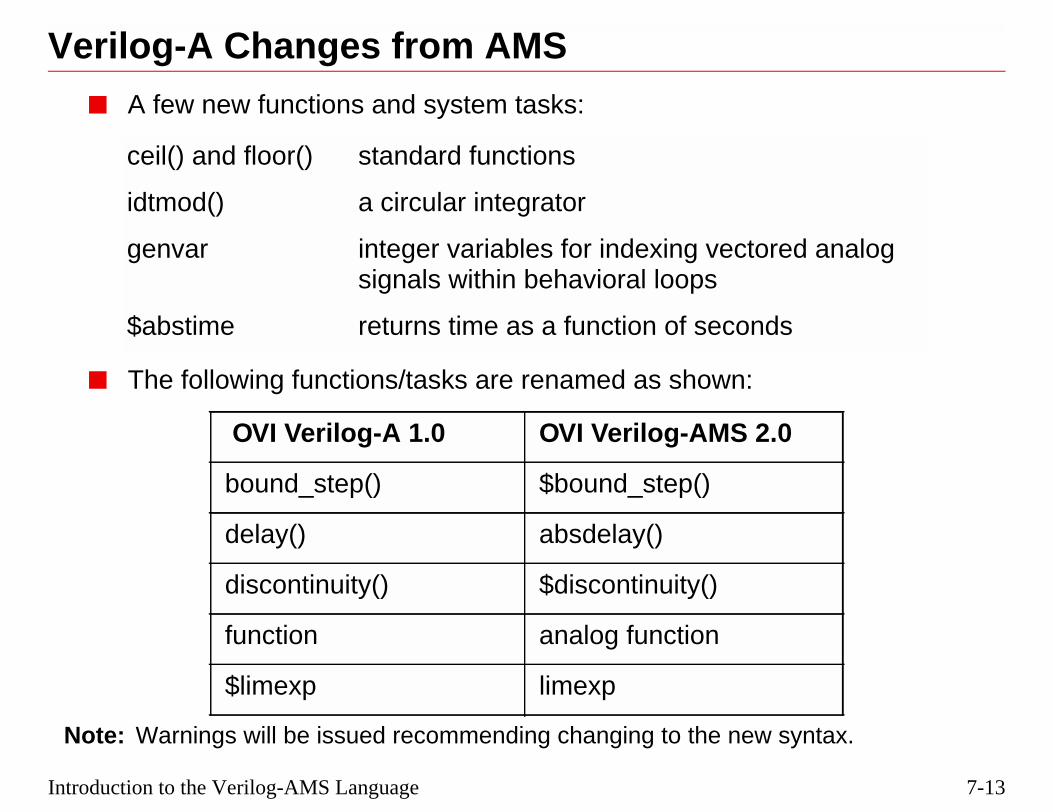
7-13
syntax.
d analog
s
Introduction to the Verilog-AMS Language
Verilog-A Changes from AMS■ A few new functions and system tasks:
■ The following functions/tasks are renamed as shown:
Note: Warnings will be issued recommending changing to the new
ceil() and floor() standard functions
idtmod() a circular integrator
genvar integer variables for indexing vectoresignals within behavioral loops
$abstime returns time as a function of second
OVI Verilog-A 1.0 OVI Verilog-AMS 2.0
bound_step() $bound_step()
delay() absdelay()
discontinuity() $discontinuity()
function analog function
$limexp limexp

7-14
Verilog-A Changes from AMS
its.
s to be replaced by
s.
-AMS are listed in
3/10/05 Virtuoso AMS Designer
■ $realtime returns to its digital definition, scaled to `timescale un
■ In analog blocks, the $realtime operator used in Verilog-A need$abstime.
■ The Modulus function now supports both real and integer result
■ Summaries of Verilog-A statements and the changes to VerilogAppendix A.

7-15
gered D Flip Flop
rst, q, qb);
or negedge rst)
Introduction to the Verilog-AMS Language
Verilog-D Modules
Verilog-D modules consist of:
■ Keywords “module” and“endmodule”
■ A model name and port list
■ Port declarations
❏ Direction
❏ Data Type
■ Behavior
❏ Continuous assignment
❏ Initial procedural block
❏ Always procedural block
■ Structure
//Positive edge trig//with reset//module DFF (d, clk,
input d, clk, rst;output q, qb;
reg q;
assign qb = ~q;
initial q = 0;
always @(posedge clkif (!rst)
#1 q <= 0;else
#1 q <= d;
endmodule

7-16
he right-siden of the nextnt. Without the <,n of the next
ioral block.
3/10/05 Virtuoso AMS Designer
■ The <= symbol is a “non-blocking” assignment of the value of texpression to the left-side signal or variable, where the executiostatement is not controlled by completion of the current statemethe = symbol indicates a “blocking” assignment, where executiostatement is based on the execution of the current statement.
■ The “reg” datatype (for register) applies to the output of a behav
■ The #1 is a delay of one time unit.

7-17
Deasier to simulate.
code for a nand gate 1ns/1nsynand2 (Y, A, B);;
Y= ~(A & B);
e
og BehavioralCode
Introduction to the Verilog-AMS Language
Behavioral Representation Using Verilog-Behavioral modules are a higher level of abstraction and are
// Data-flow`timescalemodule minput A, Boutput Y;
assign #1
endmodul
Vdd
Vss
A
B
Y
AB
Y
A B
Y
Vdd
Vss
Physical Layout
Transistor-levelSchematic
Symbol
Veril

7-18
Behavioral Representation Using Verilog-D
of the negation (~)y of one time unit.Y is considered of
3/10/05 Virtuoso AMS Designer
The “assign” statement indicates a continuous assignment of the resultof the bit-wise binary AND (&) of A and B to the output Y after a delaThe time unit is defined by the `timescale directive as 1ns. By default,datatype “wire.”

7-19
ule can beral example of a
instance_name,
Q
Qb
or-levelatic
Introduction to the Verilog-AMS Language
Instantiating Verilog-D Modules■ The nand gate defined by its behavior in a Verilog mod
instantiated in another Verilog module, as in this structuReset-Set Flip-Flop.
■ Verilog structural statements contain the child_module, and ports.
// Structural code for an RS_FF`timescale 1ns/1nsmodule RS_FF (Q, Qb, R, S);input R, S;output Q, Qb;mynand2 n1 (Q, R, Qb);mynand2 n2 (Qb, S, Q);endmodule
R
S
Q
Qb
Vdd
Vss
R
S
Verilog Structural Code SymbolicRepresentation
TransistSchem
n1
n2
StructuralStatements

7-20
Instantiating Verilog-D Modules
coupled latch, and
3/10/05 Virtuoso AMS Designer
This is a structural instantiation of two mynand2 modules into a cross-connecting their signals with nets Q, Qb, R, and S.

7-21
analog circuitsnctions to describe
of 10000.
to differentiateed in the file
Av
Av = 10,000
Inn
Out
Inp
Introduction to the Verilog-AMS Language
Verilog-A Modules■ Verilog-A modules describe the behavior or structure of
using code similar to Verilog-D, but employing analog fubehavior.
■ This example is of a simple op-amp with an internal gain
■ Verilog-A and Verilog-AMS require the use of disciplinesanalog signals from digital signals. Disciplines are defindisciplines.vams.
//Simple Op-Amp`include “disciplines.vams”`include “constants.vams”
module myopamp (out, inn, inp);input inn, inp;output out;electrical inn, inp, out;parameter real gain = 10000;
analog beginV(out) <+ V(inn,inp)*(-gain);
end
endmodule
Compiler Directives
Port Declarations
Parameter Declaration
Disciplines
Analog Behavioral Block
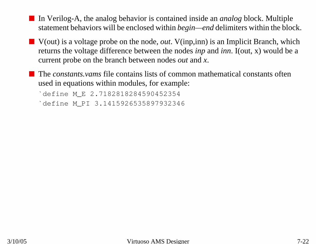
7-22
Verilog-A Modules
block. Multiplers within the block.
icit Branch, whichut, x) would be a
constants often
3/10/05 Virtuoso AMS Designer
■ In Verilog-A, the analog behavior is contained inside an analogstatement behaviors will be enclosed within begin—end delimite
■ V(out) is a voltage probe on the node, out. V(inp,inn) is an Implreturns the voltage difference between the nodes inp and inn. I(ocurrent probe on the branch between nodes out and x.
■ The constants.vams file contains lists of common mathematicalused in equations within modules, for example:`define M_E 2.7182818284590452354
`define M_PI 3.1415926535897932346

7-23
in a higher level
el amplifier design,f two op-amps and
must be defined
Structure
Signal source
Introduction to the Verilog-AMS Language
Instantiating Verilog-A Modules■ The op-amp module can be instantiated more than once
module, with different gains passed to each.
■ The example here is the analog testbench for the top-levwhich provides a signal source, structural instantiations ogain setting resistors, and interconnects.
■ For analog simulators, a global reference node “ground”somewhere in the hierarchy.
`include “disciplines.vams”`include “constants.vams”
module top;electrical fb,e,out,gnd;ground gnd;
myopamp #(.gain(20000)) O1 (fb, fb, in);myopamp O2 (out, e, gnd);resistor #(.r(10000)) R1 (fb,e);resistor #(.r(20000)) R2 (out,e);vsource #(.type(“sine”),.sinedc(0),.freq(1e6),.ampl(1)) V1 (in,gnd);
endmodule

7-24
Instantiating Verilog-A Modules
out
3/10/05 Virtuoso AMS Designer
■ The structural code above represents the following schematic:
O1O2
20,000
10,000efb
inAv=20k
Av=10kvsin
R1
R2

7-25
ers.
val,5n,2n,2n);
TER
Introduction to the Verilog-AMS Language
Comparing Analog and Digital ModulesNote the differences between simple analog and digital invert
`include “disciplines.vams”
module diginv (in, out);input in;output out;logic in,out;wire out;
assign #2 out = ~in;
endmodule
`include “disciplines.vams”
module anainv (in,out);input in;output out;electrical in,out;real outval;parameter real vth=2.5;
analog beginif (V(in) > vth)
outval = 0;else
outval = 5;
V(out) <+ transition(outendendmodule
ANALOG INVERDIGITAL INVERTER

7-26
Comparing Analog and Digital Modules in AMS
continuous signalt). Its format is:me [, timetol
owever, if the riseted to the time unit
is an object that isknown value.
for time stepsdicates that a time
ound-off precision
ned a value in ae outside of a
he datatype “wire.”
3/10/05 Virtuoso AMS Designer
■ The transition filter used in the analog module converts the disoutval into a piecewise linear waveform that is assigned to V(outransition(expr [, delay [, rise_time [, fall_ti]]]]
❑ Very short rise and fall times can slow down the simulation. Hand fall are set to 0, then they default to a value somewhat relaspecified in the `timescale directive.
❑ Make sure that the expression used in the transition statementactually transitioning, and not a variable or signal with an un
■ A timescale directive `timescale 1ns/100ps sets the default scaleduring simulation. A typical setting would be 1ns/100ps, which instep for a digital module would be 1ns, while the 100ps sets the rfor the simulator.
■ In a Verilog-D module, a signal is of datatype “reg” if it is assigbehavioral block (initial or always). If a signal is assigned a valubehavioral block, as in the Digital Inverter shown above, it is of t

7-27
ch between nodes
Introduction to the Verilog-AMS Language
The Contribution Operator■ Represented by a <+ symbol
■ Unique to Verilog-A and Verilog-AMS
■ Accumulates the voltage to a node or a current to a bran
module rlc (a,b);electrical a,b;parameter R = 1 exclude 0;parameter C = 1;parameter L = 1 exclude 0;
analog beginI(a,b) <+ V(a,b)/R;I(a,b) <+ C*ddt(V(a,b));I(a,b) <+ idt(V(a,b))/L;
endendmodule

7-28
The Contribution Operator
e datatype of they ranges, or with
s. As d changescause the.
ixed-Signal
3/10/05 Virtuoso AMS Designer
■ If a parameter is not assigned a datatype, it will be inferred by thdefault value. Permissible values of parameters can be limited bexcluded values as shown above.
■ Here is another example of how the Contribution Operator workfrom 0 to non-zero, V(outsig) will change from +1.0 to +4.0, beContribution Operator accumulates the values assigned to outsig
Note: You can explore this behavior further in the optional lab in Module : MSensitivities (Optional).
analog begin
if (d == 0)
V(outsig) <+ 0.0;
else
V(outsig) <+ 3.0;
V(outsig) <+ 1.0;

7-29
als
een modules by
Introduction to the Verilog-AMS Language
A Verilog-AMS Module■ A Verilog-AMS Module has both analog and digital sign
Reduce or eliminate the need for Connect Modules betwconnecting analog or digital signals to matching ports.
■ A Verilog-AMS Module can be:
❏ Behavioral—Defines how the module performs
❏ Structural—Interconnects various submodules
❏ Or contain both behavior and structure
■ A Verilog-AMS Module may contain:
❏ Compiler directives
❏ Port declarations
❏ Signal disciplines
❏ Parameter declarations
❏ Variable declarations
❏ Digital blocks
❏ ONE analog block
❏ Structure
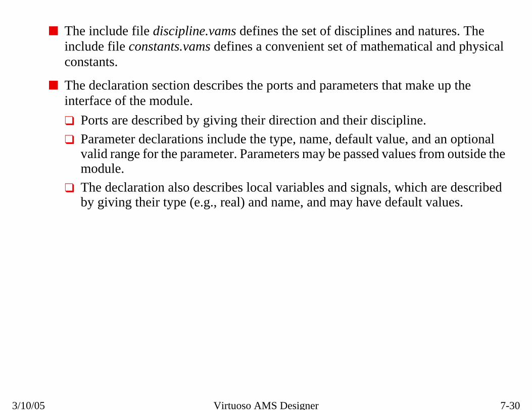
7-30
A Verilog-AMS Module
d natures. Thetical and physical
make up the
ine.
and an optionals from outside the
ich are describedult values.
3/10/05 Virtuoso AMS Designer
■ The include file discipline.vams defines the set of disciplines aninclude file constants.vams defines a convenient set of mathemaconstants.
■ The declaration section describes the ports and parameters that interface of the module.
❑ Ports are described by giving their direction and their discipl
❑ Parameter declarations include the type, name, default value,valid range for the parameter. Parameters may be passed valuemodule.
❑ The declaration also describes local variables and signals, whby giving their type (e.g., real) and name, and may have defa

7-31
avior inside a
analog block.
e of the analog
only items insideontext; everything
ber of initial and
nalog or digital
Introduction to the Verilog-AMS Language
Verilog-AMS Modules■ Have separate blocks for defining analog and digital beh
module.
❏ Analog behavior can only be described inside of the
❏ Analog functions can be created, but only used insidblock.
❏ There can be only one analog block per module, andof an analog block are considered part of the analog celse is the digital context.
❏ Digital behavioral can be described inside of any numalways blocks.
■ May contain structural instantiations that exist outside ablocks

7-32
3/10/05 Virtuoso AMS Designer
7-33
ntroln
lock
ion Statement
ns
Introduction to the Verilog-AMS Language
A Behavioral Verilog-AMS Module
An AMS Sample-and-Hold
`include “disciplines.vams”`include “constants.vams”
module sample (out, trigger, in);output out;input trigger, in;electrical out, in;logic trigger;
parameter real delay=1n from (0:inf);real held;
analog begin@(posedge(trigger))held=V(in);
V(out) <+ transition(held,delay);end
endmodule
Digital Cowithin a
Analog B
Contribut
Declaratio
CompilerDirectives

7-34
A Behavioral Verilog-AMS Module
ule.
AMS.t blocks such as
when the block is
ks are evaluated
3/10/05 Virtuoso AMS Designer
■ This analog block defines the behavior of a Verilog-AMS mod
■ Each statement is evaluated on every time step.
■ Either event-driven or continuous time models can be written inEvent-driven behavior, as shown above, is described using even@(posedge(trigger)).
❑ trigger is a digital signal, as can be seen in the declarations.
❑ The statements contained within the block are only evaluatedtriggered by an event.
■ Those statements inside the analog block but outside event bloccontinuously.
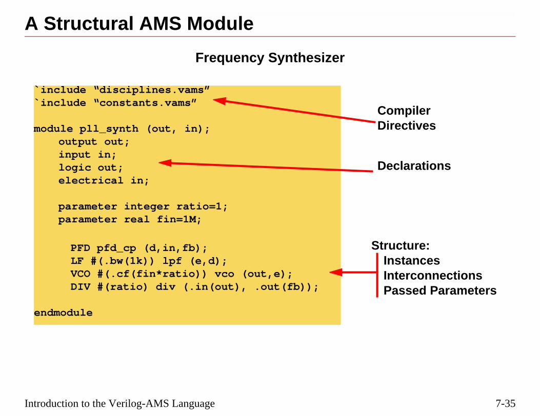
7-35
ture:tancesrconnectionssed Parameters
larations
pilerctives
Introduction to the Verilog-AMS Language
A Structural AMS Module
Frequency Synthesizer
`include “disciplines.vams”`include “constants.vams”
module pll_synth (out, in);output out;input in;logic out;electrical in;
parameter integer ratio=1;parameter real fin=1M;
PFD pfd_cp (d,in,fb);LF #(.bw(1k)) lpf (e,d);VCO #(.cf(fin*ratio)) vco (out,e);DIV #(ratio) div (.in(out), .out(fb));
endmodule
StrucInsIntePas
Dec
ComDire

7-36
A Structural AMS Module
e:
ctural context, butclared.
t is not connected
.
, passed
nections)
out
3/10/05 Virtuoso AMS Designer
This is a block-diagram representation of the pll_synth structure abov
■ Nodes (analog nets) can be used without being declared in a strubefore they can be used in a behavioral context, they must be de
❑ If the net is vectored (i.e., a bus) it must be declared even if ito one of the module ports.
■ Structure and behavior can be included within the same module
■ The structural statements include the module, the instance nameparameters, and the interconnections in the following format:component_name #(parameters) instance_name (con
PFD LF VCO
DIV
in
fb
d e
inout

7-37
ompOut));
dacOut);
Introduction to the Verilog-AMS Language
Parameters and Ports■ Parameter passing
❏ Pass by name:
nmos #(.w(1u),.l(0.5u)) M1 (...);
❏ Pass by order:
nmos #(1u,0.5u) M1 (...);
❏ Using defparam:
defparam M1.w=1u;
■ Port connection
❏ Connect by name:
comp I2 (.inm(holdSig), .inp(dacOut), .out(c
❏ Connect by order:
nmos1 M3 (ibias, ibias, gnd, gnd);
❏ Missing ports (b8 is skipped below):
daconv I5 (b0, b1, b2, b3, b4, b5, b6, b7, ,

7-38
Parameters and Ports
odules either byngle list.
ement, which isn. Often defparam
e(value) syntax.r. Parameters needbe over-written at
lue (and so accept3).
ed
r or defparams for
3/10/05 Virtuoso AMS Designer
■ In Verilog-AMS, both parameters and ports can be passed into mname or by order, but you cannot mix these two methods in a si
■ In addition, parameters can be specified using the defparam statused to specify a parameter value separately from the instantiatiois used at the top-level of the circuit with a hierarchical name.
■ Parameters and ports are passed by name using the .paramNamWhen passing parameters by name, they can be given in any ordeonly be declared at a higher level when the default values are toa lower level.
■ When passing parameters and ports by order, one can skip a vathe default value) by simply leaving the field empty, e.g., (p1, ,p
❑ When passing by order, left-most parameters cannot be skipp
Note: Virtuoso AMS Designer currently does not support parameters by ordeanalog primitives.

7-39
ectrical (analog) or
s (electrical), buttor option
ll be automaticallymains.
be direction output
; otherwise, allion.
odule direction.
Introduction to the Verilog-AMS Language
Domains, Discipline, and Direction■ Verilog-AMS supports two domains:
❏ Discrete: used to describe digital circuits
❏ Continuous: used to describe analog circuits
■ For modules describing circuits, disciplines are usually ellogic (digital).
❏ Disciplines are defined in the disciplines.vams file.
❏ Discipline statements are required for analog modulecan be defaulted for digital modules using an elabora(-discipline logic)
❏ Disciplines determine whether a Connect Module wiinserted in the nets between modules of different do
■ Port direction is input, output, or inout.
❏ Digital behavior can only drive registers, which must
❏ For signal flow in analog ports, direction is importantanalog ports are internally considered inout in direct
❏ Port direction determines the selection of Connect M

7-40
Domains, Discipline, and Direction
3/10/05 Virtuoso AMS Designer

7-41
in simple form:
*******************er (Verilog-AMS)le that convertsponding analog signals.*******************/
al);
analog_value=vhigh;analog_value=vlow;
e; // Voltage source
Introduction to the Verilog-AMS Language
Connect ModulesConnect Modules translate analog to digital as shown below,
`include “disciplines.vams”`timescale 1ps / 100fs
/********************************************** Analog to Digital converter (Verilog-AMS)* This is a connection module that converts* analog signals to corresponding digital signals.**********************************************/
connectmodule a2dig (aVal, dVal);
input aVal;output dVal;
electrical aVal;logic dVal;
parameter real vthresh = 2.5;
reg dVal;
always beginif (V(aVal) >= vthresh)
#1 dVal = 1;else
#1 dVal = 0;end
endmodule
`include “disciplines.vams”`timescale 1ps / 100fs
/*************************** Digital to Analog convert* This is a connection modu* digital signals to corres***************************
connectmodule dig2a(dVal,aV
input dVal;output aVal;
electrical aVal;logic dVal;
parameter real vhigh = 5.0;parameter real vlow = 0.0;
assign dVal = dVal;real analog_value;
analog begin@(posedge(dVal)) @(negedge(dVal))
V(aVal) <+ analog_valuend
endmodule
A2D D2A

7-42
Connect Modules
e analog signalgering an event in
r Segregation in ahe Driver and theatement forciblyalog output. ForLanguage
sical environment,xternal supply
h will be analog eventld, as covered in a
ity and supplyctory:
3/10/05 Virtuoso AMS Designer
■ In the simplified examples shown above, note the presence of thtriggering an event in the digital module, and a digital signal trigthe analog module, which works in AMS.
■ The “assign dVal = dVal” statement is related to Driver-ReceiveConnect Module. The software breaks the connection between tReceiver connected to a mixed net. The “assign dVal = dVal” strestores the connection between the digital input and the CM anmore information, see Chapter 11 of the Cadence Verilog-AMS Reference.
■ Connect Modules can be made more complex to model any physuch as output states x or z, output voltage levels referenced to evoltages, output impedance and capacitance, rise-time, etc.
■ In the A2D module shown, the expression if V(aVal) >= vthrescontinuously evaluated. To reduce compute effort, use the crossoperator to detect positive and negative crossings of the thresholater lecture.
■ An annotated set of Connect Modules in three levels of complexvoltage are included in the Virtuoso AMS Simulator install dire
$AMSHOME/tools/affirma_ams/etc/connect_lib/

7-43
l net that has aies, similar in
ontinuous.
aster performance.
y a single driver,sion.
rarchy.
r to a VHDL real
Introduction to the Verilog-AMS Language
The wreal Datatype■ wreal is a Cadence unique datatype that declares a rea
real-valued physical connection between structural entitconcept to the “real wire” in VHDL.
❏ wreal has a time-discrete value whose real value is c
❏ wreal does not require an analog solver at all, giving f
❏ A wreal net can be used for real-valued nets driven bsuch as a continuous assignment from a real expres
■ A wreal net needs to be declared at each level in the hie
■ A wreal net can only be connected to other wreal nets, owire.

7-44
The wreal Datatype
3/10/05 Virtuoso AMS Designer
■ The following support for the wreal datatype is provided:
❑ VHDL real driving Verilog-AMS wreal
❑ Verilog-AMS wreal driving VHDL real
■ Limitations on the usage of the wreal datatype:
❑ Multiple drivers are not supported
❑ Only “in” and “out” ports are supported
❑ Tcl “force” command will not work for wreals.

7-45
measured.
.
erter.
k(clk);k;
lk=0; clk = ~clk;
wreal (out,in);
t;l in;;
t = ain; ain = V(in);
Introduction to the Verilog-AMS Language
An Example of wreal Usage■ Module top generates an analog sine-wave signal to be
■ Module a2wreal converts the analog sine wave to wreal
■ Module top then sends the wreal signal to the A2D conv
module top();electrical gnd;ground gnd;wreal win;wire[0:7] dout;vsource #(.type("sine"), .sinedc(2.5), .ampl(2.5), .freq(500K)) v1(in,gnd);a2wreal b2(win,in);w_a2d b1(dout[0:7],win,clk);clk c1(clk);endmodule
module cloutput clreg clk;initial calways #5endmodule
module a2input in;output ouelectricawreal outreal ain;assign oualways #1endmodule
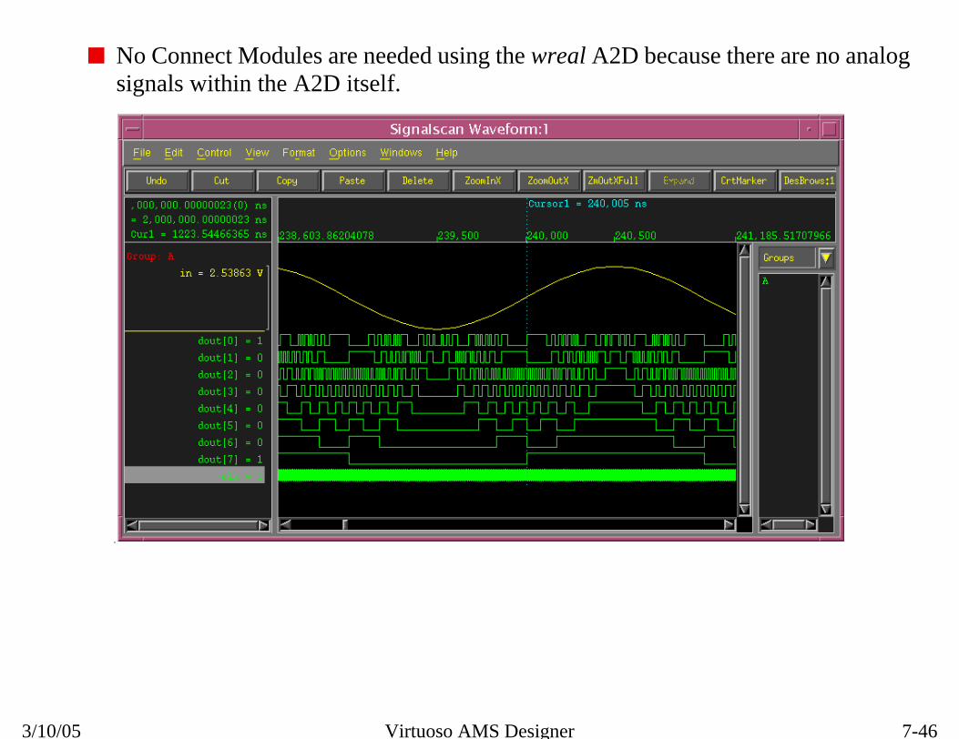
7-46
An Example of wreal Usage
here are no analog
3/10/05 Virtuoso AMS Designer
■ No Connect Modules are needed using the wreal A2D because tsignals within the A2D itself.
.

7-47
in,clk);
5.0;
lk)) begin
d for display
/starting value
=i-1) begin
> FS/2) begin
1’b1;
residue - FS/2;
= 1’b0;
sidue*2;
Introduction to the Verilog-AMS Language
A wreal A2D Converter in Verilog-AMS
■ A2D converter without an analoginput, because it uses a wrealinput.
■ The real variable win receives thevalue of the wreal in a digitalcontext.
module w_a2d(dout,
input in, clk;
output [0:7] dout;
parameter real FS=
wreal in;
reg [0:7] dout;
real residue, win;
integer i;
always @(posedge(c
win = in; //use
residue = in; /
for (i=7;i>=0;i
if (residue
dout[i] =
residue =
end
else dout[i]
residue = re

7-48
A wreal A2D Converter in Verilog-AMS
3/10/05 Virtuoso AMS Designer

7-49
ilable, depending
ility
g-D
cussed in a later
Introduction to the Verilog-AMS Language
IP Source Code ProtectionTwo different methods to encrypt/protect source code are avaon the languages being used:
■ For all HDL behavioral source files, use the ncprotect ut
❏ Verilog-AMS, Verilog-A, VHDL-D, VHDL-AMS, Verilo
■ For Spectre® source files, use spectre_encrypt utility (dismodule)
❏ netlists, model cards, subcircuits

7-50
IP Source Code Protection
3/10/05 Virtuoso AMS Designer
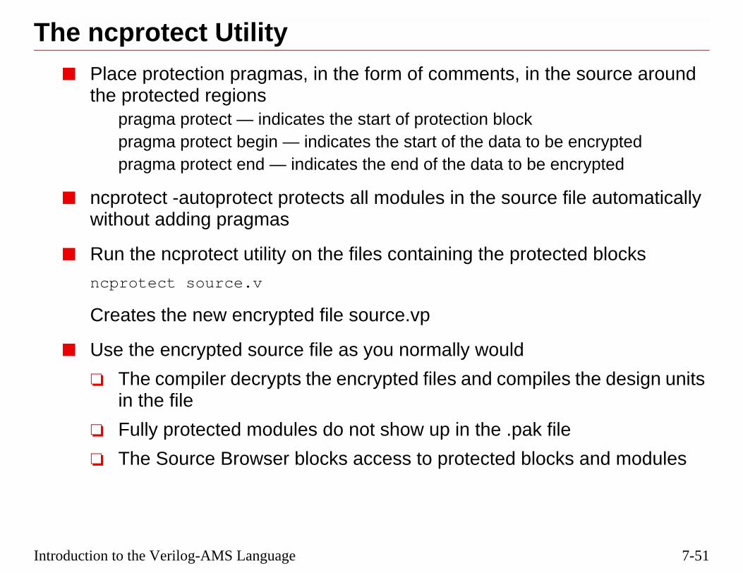
7-51
he source around
e encryptedencrypted
file automatically
cted blocks
es the design units
ile
ks and modules
Introduction to the Verilog-AMS Language
The ncprotect Utility■ Place protection pragmas, in the form of comments, in t
the protected regionspragma protect — indicates the start of protection blockpragma protect begin — indicates the start of the data to bpragma protect end — indicates the end of the data to be
■ ncprotect -autoprotect protects all modules in the sourcewithout adding pragmas
■ Run the ncprotect utility on the files containing the prote
ncprotect source.v
Creates the new encrypted file source.vp
■ Use the encrypted source file as you normally would
❏ The compiler decrypts the encrypted files and compilin the file
❏ Fully protected modules do not show up in the .pak f
❏ The Source Browser blocks access to protected bloc

7-52
The ncprotect Utility
ck:
debug, $write,
e instances of that
3/10/05 Virtuoso AMS Designer
■ The following functions do nothing when inside a protected blo
$strobe, $fstrobe, $display, $fdisplay, $debug, $f$fwrite
■ If an instance master of a Connect Module is protected, then all thmaster are also protected.

7-53
5033, IC5141, andct in the cds.lib file:
Introduction to the Verilog-AMS Language
Behavioral Mixed-Signal Model LibraryA library of Verilog-AMS models, bmslib, is included in the IClater software installs, and can be made available to the proje
<IC5141_path>/tools/dfII/samples/artist/bmslib
■ Included are parameterized Verilog-AMS models:
❏ Comp_AMS
❏ F2Vconv
❏ ProgAmp
❏ vco1
❏ DiffOpamp
❏ jitter_meter
❏ PD_proportional_out
❏ single_shot
❏ MeasDelay
❏ dac_steer_12
❏ F2V_ams

7-54
Behavioral Mixed-Signal Model Library
the ahdlLib in the
3/10/05 Virtuoso AMS Designer
This bmslib library is in addition to the Verilog-A models provided insame directory, and those generated by ModelWriter.

7-55
?
usage in designs?
Introduction to the Verilog-AMS Language
Review1. What is the main advantage of using the wreal datatype
2. What models libraries are available for further study and

7-56
Review
ating Connect
ModelWriter
3/10/05 Virtuoso AMS Designer
1. Speeds up simulation by making interfaces all digital and eliminModules.
2. bmslib (Verilog-AMS models), ahdlLib (Verilog-A models) and(Verilog-A models)

7-57
dules
Introduction to the Verilog-AMS Language
Labs
Lab 7-1 Exploring Verilog-AMS Language and Connect Mo
Lab 7-2 Running the wreal A2D Converter (Optional)

7-58
Labs
3/10/05 Virtuoso AMS Designer

®
March 10, 2005
Module 8
8 Discipline n
Resolutio
8-2
3/10/05 Virtuoso AMS Designer
8-3
ed
nect Modules
methods
connections in
Discipline Resolution
Topics in this Module■ More details about how Connect Modules are construct
■ Understanding connect rules and how to override them
■ Exploring driver-related issues and supply-sensitive Con
■ Virtuoso® AMS Designer’s automatic discipline resolving
■ Using out-of-module references (OOMRs) and inheritedAMS

8-4
Discipline Resolution
urate simulations
stands the other’ss necessary.
Connect Modules
tain applications,re accurate results
e from outside theforce disciplines
ignals by adding aa port discipline
3/10/05 Virtuoso AMS Designer
■ Connecting analog circuits to digital circuits and performing accis not a trivial matter.
❑ Neither domain (analog/continuous or digital/discrete) underlanguage and signals. Translation between the two domains i
■ Virtuoso AMS Designer handles this automatically by insertingat every interface between the two domains.
❑ This automatic insertion can be overridden by the user in cerwhere a different choice of Connect Module will produce moin the simulation.
■ OOMR (Out of Module Reference) means a hierarchical referencmodule in which the reference appears. OOMRs can be used to and set design variables lower in the hierarchy.
■ Inherited connections allow you to selectively override global snet expression to a wire or pin in a schematic, or an attribute to declaration.

8-5
domains: discrete
continuous, or
l world is black and
ontinuous) signalsbe interpreted
AnalogDomain
Discipline Resolution
Simulation Domains■ Simulation needs to take place across two incompatible
and continuous.
❏ Analog signals are continuous. Digital signals are disdiscrete.
❏ The analog world exists in shades of grey. The digitawhite.
■ The purpose of Connect Modules is to translate analog (cto digital (discrete) signals, and vice-versa, so they can correctly in the new domain.
Digital toAnalogConnectModule
Analog toDigitalConnectModule
AnalogDomain
DigitalDomain
8-6
Simulation Domains
Connect Modules
done byeeping track of
3/10/05 Virtuoso AMS Designer
■ Three items need to be defined to allow automatic insertion of theto translate between domains:
❑ Connect Modules
❑ Connect Rules
❑ Discipline Resolution Algorithm
■ The partitioning of the design into analog and digital sections isdetermining the disciplines and domains of every net segment, kwhere analog or digital nets connect to digital or analog ports.

8-7
es on which they
= “A”;= I;= Charge;
= “V”;= V;= Flux;
ures
Discipline Resolution
DisciplinesThe disciplines.vams file defines the disciplines and the naturare based.
nature Currentunitsaccessidt_nature
endnature
nature Voltageunitsaccessidt_nature
endnature
// Conservative disciplinediscipline electrical
potential Voltage;flow Current;
enddiscipline
// Signal flow disciplinesdiscipline voltage
potential Voltage;enddiscipline
discipline currentpotential Current;
enddiscipline
discipline logicdomain discrete;
enddiscipline
Disciplines Nat

8-8
Disciplines
ect Modules needisciplines. The
current, is
High and Low,e domain supportstes predefined for
3/10/05 Virtuoso AMS Designer
■ There can also be magnetic or mechanical disciplines, but Connto be defined to translate between them and electrical or logic dlocation of the disciplines.vams file is:$CDSHOME/tools/spectre/etc/ahdl/
■ The nature used in single-nature disciplines, such as voltage or considered a potential.
■ The discrete domain implies specifically defined states, such asTrue and False, or 1 and 0. In Virtuoso AMS Designer, the discretthe normal logic states for Verilog-D (1, 0, x, and z), and the staVHDL-D data-types, such as std_logic (0, 1, Z, L, H, -).

8-9
module used to
ct2logic)
ic2elect)
e (e.g., a2d, d2a,l perform the sameg to digital domain,
ports of type inout
mplexity, including:
Discipline Resolution
Connect Module Types■ Connect Modules are a special version of a Verilog-AMS
translate between discrete and continuous domains.
❏ Translate analog outputs to digital inputs (a2d or ele
❏ Translate digital outputs to analog inputs (d2a or log
■ Connect Module names are chosen to reflect their usagbidir, elect2logic, logic2elect, L2E, E2L) although they albasic function, which is translating signals from the analoand vice-versa.
■ Bi-directional Connect Modules (Bidir) connect electricalwith logic ports of type inout.
■ Connect Modules can be written with various levels of co
❏ input thresholds
❏ delays, rise and fall times
❏ output impedance
❏ power supply sensitivity
❏ parameters

8-10
Connect Module Types
rather than during
ncsim> prompt
odules used, enter:
a Tcl file that can
3/10/05 Virtuoso AMS Designer
■ Connect Modules are inserted at the elaboration phase in AMS,netlisting as is done in Verimix (SpectreVerilog).
■ The Connect Modules used in a design can be viewed from theusing either of the following Tcl commands:
❑ To list the net disciplines for each module and the Connect Mncsim> scope -disci -all -recu
❑ To list just the Connect Modules, enter:ncsim> scope -aicms -all -recu
❑ Aliases can be created for these scope commands and put in be included during a simulation.ncsim -amslic top -input mycommands.tcl ...

8-11
Rules to tell thert, based on the
r this particular inserted.
odules referencedfile used in the last
t2logic
Discipline Resolution
Connect Rules■ Each mixed-signal simulation needs to include Connect
elaborator what kinds of Connect Modules (CMs) to insedisciplines and the flow direction.
■ A Connect Rule file lists the Connect Modules chosen fosimulation, and can add options to control how they are
■ A simple Connect Rule File defines the set of Connect Mby the mixedsignal connect rule, as shown here in thelab, crules.v:
// This module defines the connectrules for elec
// and logic2elect
connectrules mixedsignal;
connect elect2logic;
connect logic2elect;
endconnectrules
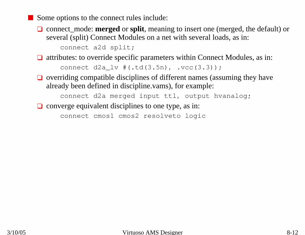
8-12
Connect Rules
ed, the default) oras in:
dules, as in:
ng they have
log;
3/10/05 Virtuoso AMS Designer
■ Some options to the connect rules include:
❑ connect_mode: merged or split, meaning to insert one (mergseveral (split) Connect Modules on a net with several loads,
connect a2d split;
❑ attributes: to override specific parameters within Connect Moconnect d2a_lv #(.td(3.5n), .vcc(3.3));
❑ overriding compatible disciplines of different names (assumialready been defined in discipline.vams), for example:
connect d2a merged input ttl, output hvana
❑ converge equivalent disciplines to one type, as in:connect cmos1 cmos2 resolveto logic

8-13
ule inserted for allstatement.
fanout port.
onnect modulese more accurately
Split
Digital
Digital
Digital
Discipline Resolution
Merged vs. Split Connect Rules■ merged indicates there should be only one Connect Mod
the fanout ports on a signal that match a given connect
■ split indicates there should be one Connect Module per
The tradeoff is between simulation time and accuracy. More ctake longer to simulate. But loading effects on each net may btreated with split CMs.
Merged
AnalogAnalog
Digital
Digital
Digital
A2D CMA2D CMs
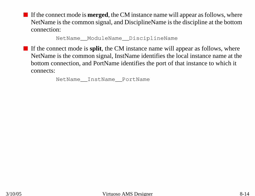
8-14
Merged vs. Split Connect Rules
r as follows, wherepline at the bottom
as follows, wherestance name at theance to which it
3/10/05 Virtuoso AMS Designer
■ If the connect mode is merged, the CM instance name will appeaNetName is the common signal, and DisciplineName is the disciconnection:
NetName__ModuleName__DisciplineName
■ If the connect mode is split, the CM instance name will appear NetName is the common signal, InstName identifies the local inbottom connection, and PortName identifies the port of that instconnects:
NetName__InstName__PortName

8-15
modules and templates for
lds
es to x after tx
analog output
ance for 0, 1, x, or z
sitions
olds
o feedback)
ble impedance
ersions
Discipline Resolution
Provided Connect ModulesA variety of more complex (but faster for simulation) connect connect rules are provided in the IUS53 install path for use asadapting to a particular technology:
“Complete Connect Modules”
■ E2L: full electrical-to-logic conversion with input thresho
❏ Converts analog voltage to logic levels of 0, 1 or x
❏ Suppresses x output on normal transitions (digital godelay)
■ L2E: full logic-to-electrical conversion with feedback from
❏ Drives electrical pin with separate voltage and imped
❏ Includes separate risetimes for up, down, and z tran
“Simple Connect Modules”
■ E2L_0: two-level logic output based on two input thresh
■ L2E_0: two-level electrical output from logic input (with n
■ L2E_1: four-level electrical output 0, 1, x, z with reasona
Bi-directional Connect Modules in both complete and simple v

8-16
Provided Connect Modules
ect_lib
nnect Rules
d referenced in the
3/10/05 Virtuoso AMS Designer
■ The path for the install Connect Modules and Connect Rules is:<IUS53_install_path>/tools/affirma_ams/etc/conn
■ Older sets of Connect Modules (logic2elect, elect2logic) and Co(mixedsignal) are also provided to support legacy simulations.
■ The provided connect modules and rules may be pre-compiled ancds.lib.

8-17
-voltage specificConnect Modules.
ated as completelab arguments:
deling of problemsas analog loadingnd Bidir.
ectrical-to-logicl Connect Module
apability as the fullffects.
el digital-to-analogct Modules,nterfaces.
Discipline Resolution
Provided Connect RulesConnRules18.v, ConnRules3.v, and ConnRules5.v are supplysets of connect rules provided in the same install path as the
■ Each voltage-specific connect rule can be further design(_full), mid-range (_mid) or basic (_basic). Example nce
ncelab top ConnRules_3V_basic ...
ncelab pll_top ConnRules_5V_mid ...
ncelab ring ConnRules_18V_full ...
■ The Complete connect rules (_full) enable reasonable mothat can occur across an analog/digital boundary, such effects. This set uses the Connect Modules L2E, E2L, a
■ The Midrange connect rules (_mid) use the complete elConnect Module E2L with the simplified logic-to-electricaL2E_1. This rule set has the same logic level handling cset, but without the analog feedback to handle loading e
■ The Basic connect rules (_basic) provides simple two-levconversion using the E2L_0, L2E_0, and Bidir_0 Conneassuming there are no issues with x or z signals at the i

8-18
Provided Connect Rules
odules. (18 stands
tion and discipline
a Bidir CM is
3/10/05 Virtuoso AMS Designer
■ The number indicates the supply voltage passed to the Connect Mfor 1.8V)
■ The Connect Module to be inserted is determined based on direcof the ports being connected, as shown in the following table:
■ If either of the ports is inout, with different port disciplines, theninserted.
Direction
OUT IN CM Inserted
Dis
cipl
ine electrical logic E2L
logic electrical L2E

8-19
inout in directionw in both directions
ectional pins.
l
Discipline Resolution
Bi-Directional Connect ModulesBi-directional Connect Modules connect digital ports that arewith analog ports that are inout in direction, providing signal flosimultaneously.
Bidir: full bi-directional conversion
■ Identical to L2E Connect Module, but defined with bi-dir
Bidir_0: simple bi-directional conversion
■ Acts as L2E_1 when the logic pin is driven by 0, 1, or x
■ Acts as E2L when the logic pin is undriven or z.
DigitaAnalog
Bi-Directional Wire

8-20
Bi-Directional Connect Modules
3/10/05 Virtuoso AMS Designer

8-21
same node withe conflict of infinite
so the conflict can
Analog
Ms with finiteutput impedance
Discipline Resolution
Solving Rigid Branches■ A rigid branch (short) occurs when two drivers drive the
conflicting signal levels, and there is no way to resolve thcurrents drive capability.
■ The solution is to add a finite output impedance to CMs be resolved without infinite currents:
connectmodule d2a(dVal,aVal);
input dVal; output aVal;
logic dVal; electrical aVal, out;
parameter real rout=1.0;
real x;
assign dVal = dVal;
analog begin
@(posedge(d)) x=5.0; //or 3.3
@(negedge(d)) x=0.0;
// drive intermediate node
V(out) <+ transition(x,3n,3n);
// resistive output, rout
I(aVal, out) <+ V(aVal,out) / rout;
end
endmodule
Digital
Digital
Co

8-22
Solving Rigid Branches
the current
3/10/05 Virtuoso AMS Designer
The Connect Module above inserts a resistor in the output net to limitcapability.
V(aVal)rout
I(aVal,out)
d2a
V(dVal) V(out)
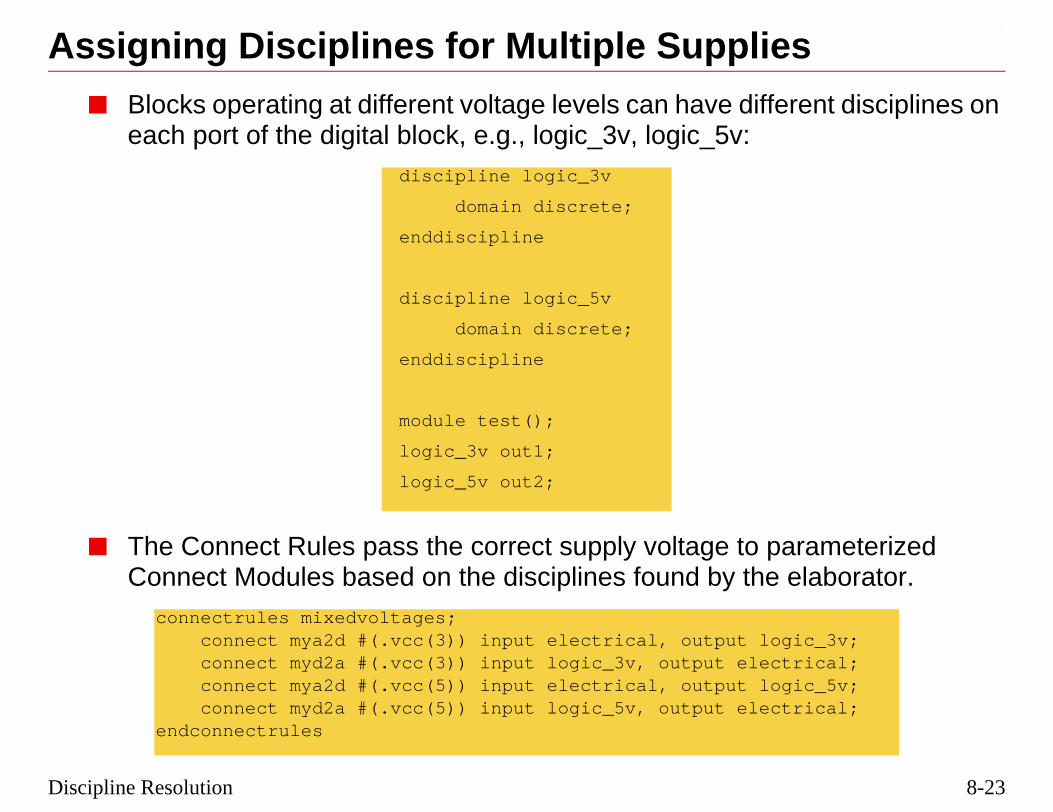
8-23
srent disciplines on
arameterized elaborator.
gic_3v;trical;gic_5v;trical;
Discipline Resolution
Assigning Disciplines for Multiple Supplie■ Blocks operating at different voltage levels can have diffe
each port of the digital block, e.g., logic_3v, logic_5v:
■ The Connect Rules pass the correct supply voltage to pConnect Modules based on the disciplines found by the
discipline logic_3v
domain discrete;
enddiscipline
discipline logic_5v
domain discrete;
enddiscipline
module test();
logic_3v out1;
logic_5v out2;
connectrules mixedvoltages; connect mya2d #(.vcc(3)) input electrical, output lo connect myd2a #(.vcc(3)) input logic_3v, output elec connect mya2d #(.vcc(5)) input electrical, output lo connect myd2a #(.vcc(5)) input logic_5v, output elecendconnectrules

8-24
Assigning Disciplines for Multiple Supplies
here the Connectrough an inherited
3/10/05 Virtuoso AMS Designer
■ Another method is to use supply-sensitive Connect Modules, wModule level is defined by the digital block it is connected to thconnection. This will be described later in this lecture.

8-25
nd an analog net.
vity, you can makee digital port,
ule
digital port.fine the attributes on
ou add the attributes
andl.
vity attributes have
Discipline Resolution
Supply-Dependent Connect ModulesConnect Modules are always inserted between a digital port a
■ By adding attributes groundSensitivity and supplySensitithe Connect Module sensitive to the supply signals on thregardless of port direction. Two steps are required:
❏ Inserting the necessary attributes in the connect mod
❏ Adding the corresponding attributes to the connected❍ If the connected digital port is part of a schematic, you de
the connected pin in the schematic.❍ If the connected digital port is defined in a text module, y
to the port definition in the module.
■ The default value associated with the groundSensitivity supplySensitivity attributes must be the name of a signa
■ You must use detailed discipline resolution or the sensitino effect.
AnalogAnalog AA DE2L L2E
\vdd!
\vss!

8-26
Supply Dependent Connect Modules
le to track theause it mimics thevisible indicationhere the action is
the Virtuoso AMS
3/10/05 Virtuoso AMS Designer
■ You want the thresholds on the electrical-to-logic connect modudigital supply voltage, rather than the analog supply voltage, becinput stage of the digital buffer or gate. The thresholds provide aof the signal levels that are valid input (high or low), and those wunknown (x).
■ For more information on supply-sensitive Connect Modules, seeEnvironment User Guide, Chapter 5.

8-27
Sensitivityrnal supply nodes,
in the IUS54
vdd;vss;
Discipline Resolution
Modifying the Connect Module for SupplyAdd the attributes for supply and ground sensitivity to the inteusing them to set the input high and low thresholds.
Note: Supply Sensitive E2L and L2E connect modules are providedinstallation, with the suffix _ss.
`include “disciplines.vams”
connectmodule elect2logic(aVal, dVal);output dValinput aVal;logic dValelectrical aValelectrical (* integer supplySensitivity = “cds_globals.\\vdd! “ ; *) electrical (* integer groundSensitivity = “cds_globals.\\vss! “ ; *) reg temp;parameter real offset = 0.5;
always beginif V(aVal) > (V(vdd,vss)/2 + offset ) //High Threshold
#1 temp = 1;else if (V(aVal) < (V(vdd,vss)/2 - offset) //Low Threshold
#1 temp = 0;else #1 temp = 1’bx;
end
assign dVal = temp; // Bind register to digital output
endmodule

8-28
Modifying the Connect Module for Supply Sensitivity
the “!” (usuallye read.
3/10/05 Virtuoso AMS Designer
In the “cds_globals.\\vdd! ” reference, the second “\” is the escape forpronounced “bang”) and the first “\” escapes the second “\” so it can b

8-29
itivityt signals, and as infined as globals in
circuit (a buffer innal Connect
“\\vss! “; *) A; “\\vss! “; *) Z;
Discipline Resolution
Modifying the Digital Port for Supply SensAdd the ground and supply sensitivities to the input and outputhe example shown, set them to the digital supply voltages dean analog block for this particular area of circuitry.
■ Adding the sensitivities will not affect the operation of thethis case), but will provide the voltage levels to the exterModule.
`include “disciplines.vams”
module bux2 (Z, A);input (* integer supplySensitivity = “\\vdd! “; integer groundSensitivity = output (* integer supplySensitivity = “\\vdd! “; integer groundSensitivity =
electrical \vss! ;electrical \vdd! ;analog begin
V(\vss! ) <+ 0.0 ;V(\vdd! ) <+ 5.0 ;
end
buf #1 (Z,A);specify
specparamt_A_Z_rise = 0.1,t_A_Z_fall = 0.1;(A +=> Z) = (t_A_Z_rise,t_A_Z_fall); // Delays
endspecify
endmodule

8-30
Modifying the Digital Port for Supply Sensitivity
3/10/05 Virtuoso AMS Designer
BUX2E2L
Supply Levels in the CMare picked up from thosedefined in BUX2
vdd!
vss!

8-31
erited
lace the definedperties attached to elsewhere in the
! is a port attributedd! ), for example.
rty values of hSup
\\vss! “; *) A;“\\vss! “; *) Z;als.\\vss! “; *) \vss! als.\\vdd! “; *) \vdd!
Discipline Resolution
Making Connect Modules Sensitive to InhConnection Values
Inherited connections can be used in the digital module to repvdd! and vss! supplies of the previous example. These are prothe instance to allow the digital supply voltages to be set fromhierarchy.
■ The inherited connection shown above for the signal \vddhaving both a name (hSup) and a value (cds_globals.\\v
■ Multiple supplies are handled by attaching different propeand lSup to different digital modules.
`include “disciplines.vams”
module bux2 (Z, A);input (* integer supplySensitivity = “\\vdd! “; integer groundSensitivity = “output (* integer supplySensitivity = “\\vdd! “; integer groundSensitivity = electrical (* inh_conn_prop_name=“lSup”; integer inh_conn_def_value=“cds_globelectrical (* inh_conn_prop_name=“hSup”; integer inh_conn_def_value=“cds_glob
buf #1 (Z,A);specify
specparamt_A_Z_rise = 0.1,t_A_Z_fall = 0.1;(A +=> Z) = (t_A_Z_rise,t_A_Z_fall); // Delays
endspecify
endmodule

8-32
Making Connect Modules Sensitive to Inherited Connection Values
sociating a nethe AMS netlister
ibutes that become
c online
ross a module. Forhapter 12.
3/10/05 Virtuoso AMS Designer
■ An inherited terminal connection in a schematic is created by asexpression with the pin that physically represents the terminal. Ttranslates inherited terminal connection expressions into port attrpart of the Verilog-AMS netlist.
■ For more information on inherited connections, see the CDSDodocumentation:
❑ Virtuoso AMS Environment User Guide, Chapter 5
❑ Virtuoso Schematic Composer User Guide, Chapter 2
❑ Inherited Connections Flow Guide
■ A specify block is a Verilog® construct to add delays to paths acmore information, refer to the Verilog-XL Reference Manual, C
BUX2E2L
Supply Levels in the CMare picked up from propertiesattached to BUX2
hsup = vdd2
lsup = dgnd
vdd2
dgnd
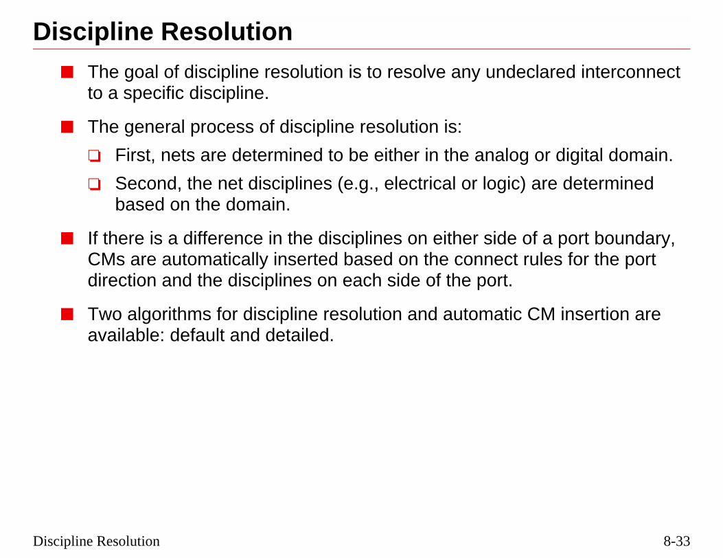
8-33
lared interconnect
or digital domain.
re determined
a port boundary,les for the port
M insertion are
Discipline Resolution
Discipline Resolution■ The goal of discipline resolution is to resolve any undec
to a specific discipline.
■ The general process of discipline resolution is:
❏ First, nets are determined to be either in the analog
❏ Second, the net disciplines (e.g., electrical or logic) abased on the domain.
■ If there is a difference in the disciplines on either side ofCMs are automatically inserted based on the connect rudirection and the disciplines on each side of the port.
■ Two algorithms for discipline resolution and automatic Cavailable: default and detailed.

8-34
Discipline Resolution
g elaborationline logic to cover
cipline of thed more CMs in
ws the use ofo add the logic
ed for all ports and
3/10/05 Virtuoso AMS Designer
■ A default discipline for the digital domain can be declared durin(-discipline logic) or using the compiler directive `default_discipdigital modules with no declared disciplines.
❑ Often with structural netlists, it’s useful not to declare the disinterconnect, so if you switch views, the algorithm doesn’t adseries.
❑ Using one of the above default discipline methodologies alloexisting Verilog-D libraries without having to modify them tdiscipline to the port declarations.
■ Analog and mixed-signal modules must have a discipline declarnodes associated with behavioral code.

8-35
t disciplines.
A
rt Boundary
oundary
Net 1
Net 3
t 5 Net 6
Analog
Digital
A
D
Discipline Resolution
Net Discipline Resolution■ Consider a hierarchy of three levels, with undeclared ne
D D
Po
Port B
Net 1
Net 2 Net 3
Net 4 Net 5 Net 6
Net 2
Net 4 Ne
Declared Disciplines
UndeclaredDisciplines

8-36
Net Discipline Resolution
n for ICs.
e analog discipline.
needs to
domains.
l, Chapter 11, forn of Connect
3/10/05 Virtuoso AMS Designer
■ Nets can have only one discipline: electrical or logic are commo
■ The nets connected to digital blocks need to be logic discipline.
■ The nets connected to analog blocks (e.g., a MOSFET) need to b
■ The Automatic Insertion of Connect Modules (AICM) algorithmdetermine:
❑ the discipline of nets connected through undeclared ports.
❑ where to insert Connect Modules between analog and digital
■ Refer to the Cadence Verilog-AMS Language Reference Manuamore information on discipline resolution and automatic insertioModules.
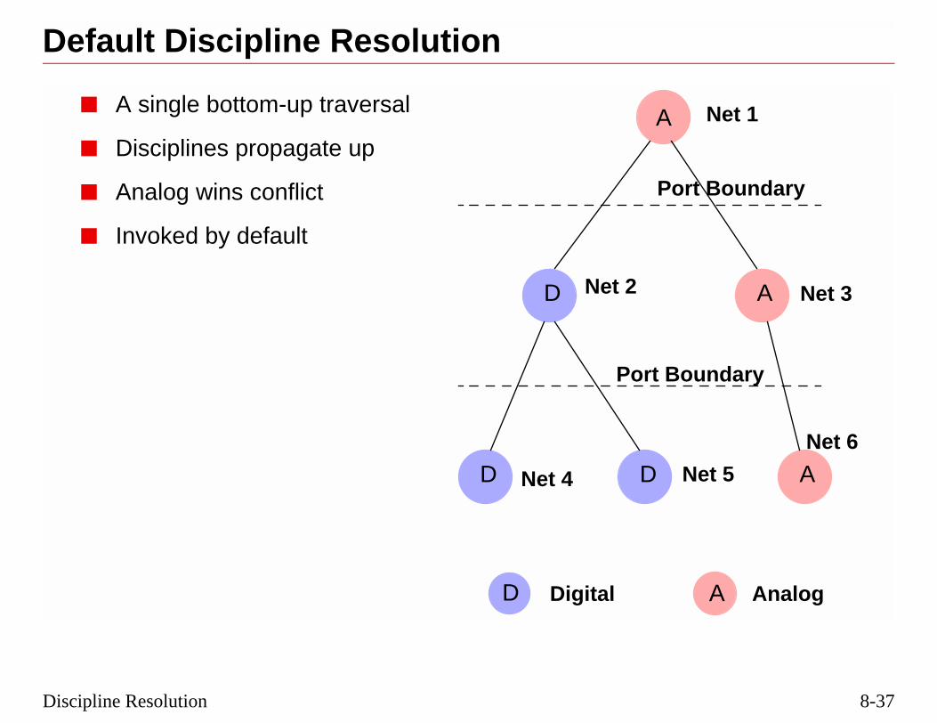
8-37
A
A
t Boundary
undary
Net 1
Net 3
et 5
Net 6
AnalogA
Discipline Resolution
Default Discipline Resolution
■ A single bottom-up traversal
■ Disciplines propagate up
■ Analog wins conflict
■ Invoked by default
A
D
D D
Por
Port Bo
Net 2
Net 4 N
DigitalD

8-38
Default Discipline Resolution
h in the hierarchy to the next level
r digital, then theis passed up along
line is assigned thempiler directivecipline logic).
.g., logic_3v andlution of the
3/10/05 Virtuoso AMS Designer
■ The default resolution method starts at the bottom of each branc(at each leaf connection) and passes the domain of that block upnet.
■ If there are two (or more) leaves, and one is analog and the othenext level net is set to be analog domain. The discipline of the netwith the domain.
■ If no discipline is found, but the domain is digital, then the discipvalue of the default discipline, which can be set either with a co(`default_discipline logic), or during the elaboration phase (-dis
■ If there are several compatible disciplines in the same domain, elogic_5v, then a connect rule can be set to predetermine the resoconflict:connect logic_3v logic_5v resolveto logic_5v

8-39
A
A
ort Boundary
Boundary
Net 1
Net 3
Net 5
Net 6
AnalogA
Discipline Resolution
Default Automatic Insertion of CMs
■ Once disciplines are resolved usingthe default algorithm, then ConnectModules are inserted betweenconflicting disciplines.
■ Upsides of the Default AICMalgorithm:
❏ Fewer Connect Modules
❏ Insertion accomplished higherin the hierarchy
❏ Faster
■ Downsides of the Default AICMalgorithm
❏ Less accurate simulationbecause fewer nets showanalog effects
A
D
D D
P
Port
Net 2
Net 4
DigitalD
CM

8-40
Default Automatic Insertion of CMs
eding instance and
tely equivalent to
3/10/05 Virtuoso AMS Designer
■ Connect Modules are inserted between the output port of the precthe net that is bound to the trailing instance.
■ The default algorithm plus merged connect mode is approximadefault in Verimix.

8-41
A
A
Port Boundary
Boundary
Net 1
Net 3
Net 5
Net 6
AnalogA
Discipline Resolution
Detailed Discipline Resolution
■ Bottom-up AND top-down traversal
■ Analog discipline propagates upand then down the hierarchy
■ Analog wins any conflict
■ Process repeats until resolved
■ Invoked with:
ncelab -dresolution
A
A
D D
Port
Net 2
Net 4
DigitalD

8-42
Detailed Discipline Resolution
pproach toare passed up and
the only exceptionhich are then
ctions.
3/10/05 Virtuoso AMS Designer
■ The detailed discipline resolution algorithm is a more accurate adiscipline resolution where only the analog domain and disciplinedown the hierarchy until all nets have a domain and discipline.
■ In this approach, virtually all unknown nets become analog, withbeing those nets sandwiched between nets of digital domains wprotected from being made analog.
■ Detailed discipline resolution must be used with inherited conne

8-43
A
A
ort Boundary
oundary
Net 1
Net 3
Net 5
Net 6
AnalogA
Discipline Resolution
Detailed Automatic Insertion of CMs
■ Once disciplines are resolvedusing the detailed algorithm, thenConnect Modules are insertedbetween conflicting disciplines.
■ Upsides of the DetailedAICM algorithm:
❏ More accurate simulationbecause more nets showanalog effects
■ Downsides of the DetailedAICM algorithm:
❏ More Connect Modules
❏ CMs lower in hierarchy
❏ More analog modeling
❏ Slower
A
A
D D
P
Port B
Net 2
Net 4
DigitalD
MergedCM

8-44
Detailed Automatic Insertion of CMs
D
Port
Net 2
4 Net 5
Boundary
3/10/05 Virtuoso AMS Designer
■ Note the merged Connect Module shown in thefigure above. If the option were set to split, thenthere would two Connect Modules shown betweenNet 2 and Nets 4 and 5.
■ The detailed algorithm plus split connect mode isapproximately equivalent to detail in Verimix.
■ Split connect mode can be a more accurate way tomodel loading factors, while merged connect modeis faster.
A
D Net
SplitCMs

8-45
orating predefined by the AICMS
log, add an OOMR
hierarchy
erarchy
Discipline Resolution
Using an OOMR Discipline Declaration■ Forcing nets to a specific discipline is useful when incorp
IP blocks to prevent an analog discipline being resolvedalgorithm at the top of the block.
■ To force a net to be digital and stop any resolution to anadeclaration to the top module of a design, as in:
module top (); //top level with structural code
logic d1.dig3.out; //OOMR
analog_blk a1(in,out);
digital_blk d1(in);
endmodule
....
module digital_blk (out); //first level down in
d_known dig1(out);
d_known dig2(out);
....
d_unknown dig3(out); //second level down in hi
endmodule

8-46
Using an OOMR Discipline Declaration
at simply meansmodule, and alsodiscipline is set on
a netDiscipline
3/10/05 Virtuoso AMS Designer
■ OOMR = Out of Module Reference. OOMR is a general term thsetting a value within one module from somewhere outside the includes setting parameters down a hierarchy. In this example, aa signal in a module from outside the module.
■ In a schematic, a net can be set to a specific discipline by addingproperty to it, and giving it a value electrical or logic.

8-47
? In a digital
t disciplines and
the project for the
pt to display the
Discipline Resolution
Review1. What discipline is commonly found in an analog domain
domain?
2. What two algorithms are used to resolve undeclared neinsert Connect Modules?
3. What files or modules must be included, or referenced, inAutomatic Insertion of Connect Modules to work?
4. What Tcl commands can be used from an ncsim> promdisciplines and/or connect modules in a design?

8-48
Review
ules
3/10/05 Virtuoso AMS Designer
1. electrical, logic
2. default, detailed
3. A connect rules file or module, and connect module files or mod
4. scope -disci -all -recu and scope -aicms -all -recu

8-49
Discipline ResolutionLabs
Lab 8-1 Exploring Discipline Resolution
Lab 8-2 Bidirectional Connect Modules (Optional)

8-50
Labs
3/10/05 Virtuoso AMS Designer

®
March 10, 2005
Module 9
9 AMS Mixed teraction
-Signal In
9-2
3/10/05 Virtuoso AMS Designer
9-3
log signals
ls
ggering events
ggering events
AMS Mixed-Signal Interaction
Topics in this Module■ Constructing digital blocks that use the values from ana
■ Constructing analog blocks that incorporate digital signa
■ Constructing digital blocks that use analog signals as tri
■ Constructing analog blocks that use digital signals as tri

9-4
AMS Mixed Signal Interaction
MS design. Whilelog-D, and VHDL,d often a more
3/10/05 Virtuoso AMS Designer
Interaction between the digital and analog domains is the heart of true AVirtuoso®AMS Designer can use modules coded using Verilog-A, Veriusing these interaction techniques will give the fastest simulations, anaccurate representation of actual circuit implementations.

9-5
l block, and
ersa.
nalog context, all
o the discretetext belongs to the
rmation and define
variable across the
in analog context
AMS Mixed-Signal Interaction
Basic Mixed-Signal Interaction in AMS■ Verilog-AMS allows:
❏ Access to analog signals and variables from a digitavice-versa.
❏ An analog event to affect a digital context, and vice-v
■ All objects are owned by a context.
❏ Statements occurring in the analog block are in the aothers are in the digital context.
❏ Behavior described within a digital context belongs tdomain, and behavior described within an analog concontinuous domain.
■ Cross-domain sensitivities enable users to exchange infodependencies across the domains.
❏ Demand sensitivity accesses a value of a signal or adomain boundary.
❏ Event sensitivity occurs when a digital event is usedor the vice versa.

9-6
Basic Mixed Signal Interaction in AMS
and analog
only one analog
allowed from any
log context.
an analog context.
th.
3/10/05 Virtuoso AMS Designer
■ In general, digital behavior is defined in initial or always blocksbehavior in analog blocks.
❑ All three types of blocks can appear in the same module (butblock per module).
■ Read operations of continuous-time and discrete-time signals arecontext.
■ Write operations of:
❑ continuous-time signals are only allowed from inside an ana
❑ discrete-time signals are allowed from any context outside of
■ Variables can only be assigned in one context, but be used in bo

9-7
in a digital module,value of the input
Analog Signal
AMS Mixed-Signal Interaction
Analog Signals in Digital ExpressionsAn analog signal value can be sampled by a digital event withas shown below. In this case, the real variable r receives the signal insig whenever the clock has a rising edge:
...
reg clock;
real r;
electrical insig;
always @(posedge(clock)) begin
r = V(insig);
end
Digital
A Real Variable
Block
assigned a valuein a Digital context
9-8
Analog Signals in Digital Expressions
thin a digitalbe assigned to a
3/10/05 Virtuoso AMS Designer
The assignment of the analog signal value to a real variable occurs wicontext. Therefore, r belongs to the digital domain. Its value can then wreal, for example.

9-9
ignals, as shown.0 volts depending
nalog Block
ital Signal
AMS Mixed-Signal Interaction
Digital Signals in Analog ExpressionsA digital signal value can be used to select between analog sbelow. Here, the analog output signal receives either 0.0 or 3on the state of the digital input d.
reg d;
electrical outsig;
analog begin
if (d == 0)
V(outsig) <+ 0.0;
else
V(outsig) <+ 3.0;
end
A
Dig

9-10
Digital Signals in Analog Expressions
not x or z, or write
3/10/05 Virtuoso AMS Designer
■ The user must take care that the digital signal has known values,modules that take those values into consideration.

9-11
es a threshold, asf d when V(in) goes
Analog
Digital
‘
Signal
Event
AMS Mixed-Signal Interaction
Analog Events in Digital Event ControlAn analog event is frequently detected when the signal crossshown below. In this case, integer i receives the binary value opast 4.5 volts in the positive direction.
electrical in;
reg d;
integer i;
always @(cross(V(in) - 4.5, +1))begin
i = d;
end
DigitalBlock
An Integerassigned avalue in aDigital context

9-12
3/10/05 Virtuoso AMS Designer
9-13
hold crossings and
etol]))
e directionment issues an
litude resolution at
n, but has a reald, so the output is
whose value is
fer to the Cadenceecting and Using
AMS Mixed-Signal Interaction
Cross and Above Functions■ The @cross function generates an event based on thres
has the form:
@(cross (expression, direction[, timetol][, valu
❏ When the analog expression crosses zero value in thspecified (+1 or -1 or 0 for both), then the cross stateevent notification.
❏ timetol and valuetol are the time resolution and ampthe crossing, and are optional.
■ The @above function works much like the cross functiovalue at t = 0. With @cross, at t = 0, nothing has crosseunknown until a crossing has occurred.
❏ In the @above function, expr1 is a “real” expression compared to 0.
@(above (expr1[,time_tol[,expr-tol]]))
❏ For more information about the @above function, reVerilog-AMS Language Reference, in Section 8, DetEvents.

9-14
3/10/05 Virtuoso AMS Designer
9-15
ves time stepmber of rejected
nue to seek a
tive solution, thenault).
nce because itpts the second for
oss=yes
r
AMS Mixed-Signal Interaction
Fast Cross OperatorAn enhancement to the cross and above operators that improcontrol for faster threshold detection. Fast Cross limits the nuattempts at reaching a threshold crossing solution.
■ Possible settings:
❏ No limited threshold reject—default setting, will contisolution until found.
fastcross = no
❏ Reject limited threshold reject. Rejects only one tentaaccepts the second solution for discrete signals (def
fastcross = discrete
❏ Reject-one limited threshold reject—fastest performarejects only one tentative solution, then always acceany signal.
fastcross = yes
■ Usage:
❏ In analog control file as a transient analysis option:
amsTran tran stop=500n errpreset=moderate fastcr
❏ Set as an argument to the AMS—Options—Simulato

9-16
Fast Cross Operator
3/10/05 Virtuoso AMS Designer

9-17
s shown below. In the value of the
Digital Event
AnalogSignal
AMS Mixed-Signal Interaction
Digital Events in Analog Event ControlDigital edges are frequently used to enable analog circuitry, athis case, when signal d has a rising edge, variable r receivesinput signal in.
real r;
reg d;
electrical in, y;
analog begin
@(posedge d)
r = V(in);
end
AnalogBlock
A Real variableassigned a valuein an Analog context.

9-18
Digital Events in Analog Event Control
ayed until the
a companion
3/10/05 Virtuoso AMS Designer
■ The execution of the statement(s) within the analog block is delpositive edge of d occurs.
■ The posedge statement has the form shown above. There is alsonegedge statement.

9-19
at defines the
e);
),10n,5n,5n);
AMS Mixed-Signal Interaction
Shared Variables■ Shared variables can be read from any context.
■ Shared variables can only be written to in the context thowner or what type of variable it is, analog or digital.
real vth;
integer cm;
always @(cross(V(in) - vth, +1 ))
cm=1’b1;
always @(cross(V(in) - vth, -1))
cm=1’b0;
analog begin
vth = (V(vcc) - V(vee)) / 2 + V(ve
v(out) <+ transition( ((cm==1)?5.0:0.0
end
DigitalBlocks
AnalogBlock
Analog VariableDigital Variable

9-20
Shared Variables
3/10/05 Virtuoso AMS Designer
■ cm is owned by the digital domain:
❑ because cm is written to in the digital block.
❑ but cm can be read by the analog block.
■ vth is owned by the analog domain:
❑ because vth is written to in the analog block.
❑ but vth can be read by the digital block.
■ A variable cannot be set in both contexts.

9-21
both domains.
of Connect
erilog-A.
ta and controlling
AMS Mixed-Signal Interaction
Mixed-Signal Modules■ Verilog-AMS is more than just Verilog-D plus Verilog-A.
❏ True AMS mixed-signal blocks include variables from
❏ Careful mixed-signal design can reduce the number Modules, which will speed up simulation times.
■ Verilog-AMS modules can:
❏ be all behavioral, all structural, or a combination.
❏ incorporate the full capability of both Verilog-D and V
❏ have digital and analog blocks interact by sharing daeach other’s events.

9-22
Mixed Signal Modules
3/10/05 Virtuoso AMS Designer

9-23
nalog domain and
:inf],
:inf];
_gain;
AnalogValue
AMS Mixed-Signal Interaction
Example 1—VCOThis is a true Verilog-AMS VCO module, with the input in the athe output in the digital domain.
`timescale 10ps/1ps
module ams_vco ( inp, inm, q );
input inp, inm; output q;
reg q;
electrical inp, inm;
parameter real center_freq=1e6 from (0
vco_gain =0.1e6 from (0
real freq2set, nexttime;
initial begin
freq2set=center_freq;
q=0;
nexttime=1.0/((freq2set+freq2set)*10p);
end
always #nexttime begin
q=~q;
freq2set=center_freq + V(inp,inm) * vco
nexttime=1.0/((freq2set+freq2set)*10p);
end
endmodule
DigitalBlocks
DigitalOutput

9-24
Example 1—VCO
is VCO and then time.
in a behavioral
than 0 to up to andthe limit, while a
tes inclusive of the
ads the differencethe gain factor to
red oscillator
e nominalescale of 10ps, the a full period of 1
3/10/05 Virtuoso AMS Designer
■ There is no need for a Connect Module between the output of thinput of a following digital block, which speeds up the simulatio
■ Note the following language details:
❑ q, the digital output, is declared to be type reg, since it is set block.
❑ The two parameters are given allowable ranges, from greaterincluding infinity. (A right parenthesis indicates greater thanleft parenthesis indicates less than the limit. A bracket indicalimit.)
■ The analog input V(inp,inm) is shown as a branch voltage that rebetween the values at the two input ports, which is multiplied byadjust the frequency of oscillation.
■ The oscillator is formed by the delay of a half period of the desifrequency.
■ The scale factor 10p indicates 10 picoseconds (10 x 10-12). At thfrequency setting of 1 MHz, nexttime equals 50000. With a timresulting output clock has a half-period of 500 nanoseconds andmicrosecond, which yields the desired 1 MHz.

9-25
ysteresis. Theal.
AnalogEvents
AMS Mixed-Signal Interaction
Example 2—ComparatorThis example shows a Verilog-AMS comparator design with hdifferential inputs are analog, while the output is a digital sign
`include “disciplines.vams”
module ams_comp (inn, inp, q);
input inn, inp;
electrical inn, inp;
output q;
reg q;
parameter real hyst = 0.05;
initial begin
q = 1’b0;
endalways @(cross(V(inp,inn)-hyst,+1))begin
q = 1’b1;
end
always @(cross(V(inp,inn)+hyst,-1))begin
q = 1’b0;
end
endmodule
DigitalBlocks

9-26
Example 2—Comparator
d digital out, therewing digital block.
ameter, can be
in, and the results.
3/10/05 Virtuoso AMS Designer
■ Again, since this module is a true AMS design, with analog in anis no need for a Connect Module between the output and a follo
■ The hysteresis in this design is symmetrical, and since it is a parchanged in a higher level module.
■ Note that the analog cross event is evaluated in the analog domatrigger the inversion of both the digital output and the hysteresis

9-27
terto the frequency of
at 1 MHz
input rising edge
on Freq
nt
AMS Mixed-Signal Interaction
Example 3—Frequency to Voltage ConverThe following example outputs an analog voltage proportionala digital input.
module F2V (in, out);input in;output out;logic in;electrical out;parameter real Fnom = 1M, Vnom = 1; //output is 1 voltparameter real dFdV = Fnom/Vnom;parameter real Tr = 1n;parameter real Rout = 100;real Tup, Freq, Vo;
initial Freq = Fnom;
always @(posedge in) begin //frequency is computed on if (Tup > 0) Freq = 1/($abstime - Tup);Tup = $abstime;
end
analog begin //analog voltage is output for any changeVo = Vnom + transition((Freq-Fnom)/dFdV,0,Tr,Tr);I(out) <+ (V(out) - Vo)/Rout; //limits output curre
endendmodule

9-28
Example 3—Frequency to Voltage Converter
tamp. At the nextse of the time, which was stored
3/10/05 Virtuoso AMS Designer
Note that Tup holds the previous value of $abstime, the system time-srising edge of the input signal, the frequency is calculated as the inverdifference between the current timestamp and the previous timestampin Tup at the last rising edge.

9-29
rt?
d an analog block?
ilog-A modules toignal modules?
AMS Mixed-Signal Interaction
Review1. What two types of sensitivities does Verilog-AMS suppo
2. Can a signal be assigned values in both a digital block an
3. Which will yield a faster simulation, connecting pure VerVerilog-D controls, or constructing Verilog-AMS mixed-s

9-30
Review
3/10/05 Virtuoso AMS Designer
1. demand and event
2. No
3. Constructing Verilog-AMS mixed-signal modules.

9-31
AMS Mixed-Signal InteractionLabs
Lab 9-1 Mixed-Signal Interaction
Lab 9-2 Writing an AMS VCO Module
Lab 9-3 Mixed-Signal Sensitivities (Optional)

9-32
Labs
3/10/05 Virtuoso AMS Designer

®
March 10, 2005
Module 10
10 AMS Mode niques
ling Tech
10-2
3/10/05 Virtuoso AMS Designer
10-3
and digital solvers
ital signals are far
AMS Modeling Techniques
Topics in this Module■ How the simulator schedules events between the analog
■ How to improve simulation results when analog and digapart in frequency

10-4
AMS Modeling Techniques
3/10/05 Virtuoso AMS Designer

10-5
ng shared memory
n) to communicate
es cooperate in
ain as practical.
igital blocks.
d down due to theengine dominates
AMS Modeling Techniques
Modeling for Speed■ Virtuoso® AMS Designer is a single-process simulator usi
that both the analog and digital solvers access.
❏ AMS does not use IPC (inter-process communicatiobetween separate analog and digital simulators.
❏ As a “non-threaded” executable, the simulation enginscheduling events.
❏ Result is increased speed of simulation.
■ Move analog modules and statements to the digital dom
❏ Use digital gates and flip-flops instead of Verilog-A.
❏ Move statements using cross, above and timer into d
■ Many SPICE-based mixed-signal simulations are slowesmall time-steps taken by the SPICE engine. The SPICEas a contributor to the elapsed simulation time.

10-6
Modeling for Speed
n time for a model for theng Virtuoso AMS1 ms. of simulated
3/10/05 Virtuoso AMS Designer
■ One 2.3GHz PLL benchmark showed an 84.8-minute simulatioSPICE-driven mixed-simulation tool with a sawtooth Verilog-AVCO. Changing the VCO to a true Verilog-AMS model and usiDesigner slashed the simulation time to 1.7 minutes for the sametime in the circuit.

10-7
AMS Modeling TechniquesMixed Simulation Comparison
Case 1:
In some applications, the mixedsignals look like this. The analogsolver is quite busy solving eachwaveform point, while the digitalsolver has far less to do.
Case 2:
In other applications, the mixedsignals look like this. The digitalsolver is much busier than the analogsolver, which has a comparativelylong time between data points.

10-8
Mixed Signal Comparison
uency.
imations.
3/10/05 Virtuoso AMS Designer
■ Case 1 may be common in RFID applications, for example.
❑ The many analog steps will dominate the simulation time.
■ Case 2 may be common in DSP or PLL applications.
❑ The analog steps may be dominated by the digital event freq
❑ The analog waveform will look like piece-wise linear approx

10-9
analog and digital
etc.
o processnt
AMS Modeling Techniques
Mixed-Signal Synchronization■ The following chart represents the handoffs between the
solvers for an A2D converter.
Analog
Digital
1
2
3 4
5
6
7
8
9
10
11
12
13
14
15 16
17
18
T1 T2 T3 T4 T5 T6
D2A
19
Backs up ta D2A eve
A2D

10-10
Mixed Signal Synchronization
il they return to
ital solver (2).
; no event affectssynchronized, so
rol back to Digital
ds off to Analog
re (at this point) ofver (11).
nversion ishands control back
ss an analog eventto T6 (16) its next17), which is back
vent at T5, and theog solver (19).
3/10/05 Virtuoso AMS Designer
■ Each solver (analog, digital) hands off an event to the other, untsynchronization.
❑ Analog solver moves from T0 to T2 (1) and hands off to Dig
❑ Digital solver moves from T0 to T1 (3) where it has an eventAnalog, so it moves on to T2 (4). Analog and Digital are nowcontrol returns to Analog (5).
❑ Analog solver now moves from T2 to T3 (6), and hands contsolver (7).
❑ Digital solver moves from T2 to T3 (8). Back in sync, so hansolver (9).
❑ Analog solver moves from T3 to T5 (10) because it isn’t awaany analog activity needed at T4 and hands off to Digital sol
❑ Digital solver moves from T3 to T4 (12), discovers a D2A conecessary (a Digital event that triggers Analog behavior), andto the Analog solver (13).
❑ Analog solver has to back up to T3 (14), moves to T4 to proce(15) in sync with the digital triggering event and then jumps scheduled analog transition. It hands off to the Digital solver (at T4.
❑ Digital solver advances to T6 (18), because it didn’t have an etwo solvers are back in sync, so it returns control to the Anal

10-11
e steps.
osedge, andh states.
corner.
. never exceed theor moderate, and 20
ls reltol and other
for liberal, 50 for
nd_step operator.
AMS Modeling Techniques
Analog Event CreationAnalog values are calculated at analog events and analog tim
■ Analog events are caused by:
❏ Event detection operators like @cross, @above, @p@negedge, create an analog event when they switc
❏ Transition statements create analog events at each
■ Analog time steps are created by the simulator:
❏ As a function of the highest frequency in the partitionIf a sinusoidal source is present in the circuit, maxstep cansinusoidal period divided by N where N is 4 for liberal, 10 ffor conservative settings for errpreset.
❏ As a function of stop time and errpreset which controsimulator options.The maxstep is also limited by SimTime/M where M is 10 moderate and 100 for conservative settings for errpreset.
❏ In response to a not-to-exceed value using the $bou

10-12
Analog Event Creation
inside a digital
ls inside an analog
S models in the
ide a digital block
nual (digital).eference Manuals
3/10/05 Virtuoso AMS Designer
@posedge, @negedge, @cross and @above are all event generators.
■ When @posedge and @negedge are used in Verilog-D modulesblock (initial or always), they generate a digital event.
■ When @posedge and @negedge are used in Verilog-AMS modeblock, they generate analog events.
■ When @cross and @above are used in Verilog-A or Verilog-AManalog block, they generate an analog event.
■ When @cross and @above are used in Verilog-AMS models ins(initial or always), they generate digital events.
This cross-domain behavior is only possible in Verilog-AMS.
Note: @posedge and @negedge are defined in the Verilog-XL Reference Ma@cross and @above are defined in the Verilog-A and Verilog-AMS R(analog).
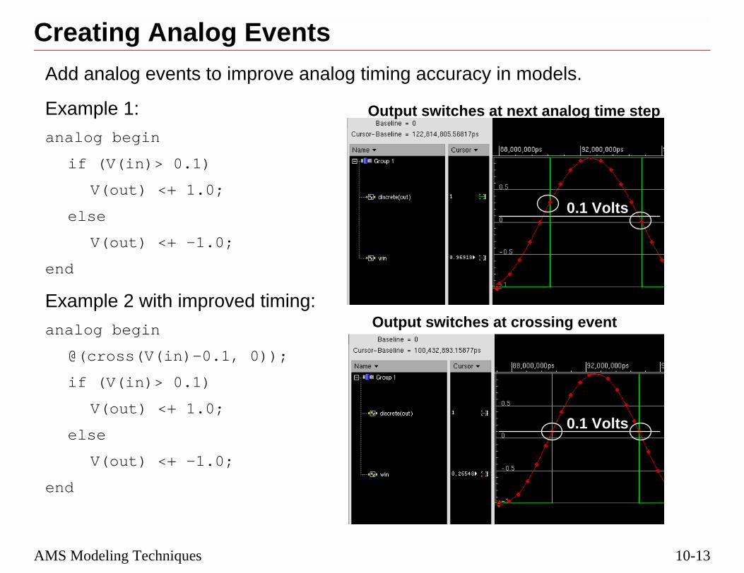
10-13
els.
nalog time step
ing event
0.1 Volts
0.1 Volts
AMS Modeling Techniques
Creating Analog EventsAdd analog events to improve analog timing accuracy in mod
Example 1:
analog begin
if (V(in)> 0.1)
V(out) <+ 1.0;
else
V(out) <+ -1.0;
end
Example 2 with improved timing:
analog begin
@(cross(V(in)-0.1, 0));
if (V(in)> 0.1)
V(out) <+ 1.0;
else
V(out) <+ -1.0;
end
Output switches at next a
Output switches at cross

10-14
f the output valueponse to the
forces the output
3/10/05 Virtuoso AMS Designer
Example 1 does not have any analog event generators, so the timing ochange is controlled by the analog time steps, which are created in ressinusoidal frequency.
Example 2 has an analog event generator, the @cross function, whichvalue to change when the @cross function detects a crossing.

10-15
occur at digitalwaveform viewert the digital event
ency = 500 kHz
AMS Modeling Techniques
Analog Events from Digital Events■ When analog is slow-moving, the analog value updates
events. This can lead to unexpected results, where the draws straight lines between analog values calculated apoints.
module read_digstate (anain,digin, anaq);
input anain, digin;
output anaq;
electrical anain, anaq;
logic digin;
analog begin
if (digin == 1)
V(anaq) <+5.0;
else V(anaq) <+0.5;
end
endmodule
Unrelated Analog Frequ
Digital Clock = 10 MHz
Analog output is setat the digital state change
DigitalValue
and interpolated between.

10-16
Analog Events from Digital Events
igital event.
a function of theare created.
in autput signal.
ich will cause the
log/Sample+Holdiangle wave above
3/10/05 Virtuoso AMS Designer
■ The value of the analog signal is sampled and updated at each d
■ Additional analog time steps are created by the analog solver asanalog signal frequency, which in this case is low, so few steps
■ The waveform viewer connects the resulting analog data points piecewise-linear fashion, thus the triangular waveshape for the o
■ This example does not handle the cases where digin is x or z, whsimulation to fail.
■ In the SimVision waveform display, using Format—Trace—Anawill change the display to hold values between updates, so the trwill be displayed as a square wave.

10-17
cyocess of interest,
AMS Modeling Techniques
Analog Time Steps From Analog FrequenA higher frequency analog signal, even if not related to the prwill generate more analog time steps:
Analog Frequency = 5 MHz
Digital Clock = 10 MHz
Analog Frequency = 50 MHz
Digital Clock = 10 MHz
Note the improvedwave shape, withrise and fall timescontrolled by the analogsample rate.

10-18
Analog Time Steps from Analog Frequency
ted highert yield predictable the same way allon time.
step size:
l rise and fall times
3/10/05 Virtuoso AMS Designer
■ Good modeling looks for predictable analog event creation:
❑ Trying to improve the analog results just by adding an unrelafrequency analog clock is not recommended because it does norise and fall times. Good behavioral modeling should behavethe time. The increased frequency will also increase simulati
❑ A $bound_step (max_size) operator will limit the maximum
❑ A more predictable method is to use transition filters to controof the analog output signal.

10-19
sinning and end of
AMS Modeling Techniques
Analog Events from Transition Statement■ Using a transition filter triggers analog events at the beg
the transition, which creates predictable time steps.
module digital_event (anain, digin,anaq);
input anain, digin;
output anaq;
electrical anain, anaq;
logic digin;
real avalue;
analog begin
@(posedge(digin)) avalue = 5.0;
@(negedge(digin)) avalue = 0.5;
V(anaq) <+ transition(avalue,2n,2n, 2n);
end
endmodule

10-20
Analog Events from Transition Statements
ted in an analog
by scheduling
3/10/05 Virtuoso AMS Designer
■ Direct events of digital signals, such as @(dVal), are not supporcontext, so posedge and negedge are used instead.
■ The transition filter yields precisely modeled rise and fall timesevents to happen at the corners.
Corners forcea time step

10-21
ext there is a digital
terpolatedevent.
Events
AMS Modeling Techniques
Reading an Analog Value in a Digital ContThe analog value is interpolated from calculated values whenevent, but not an analog event.
module read_anavalue(anain, digin, digq);
input anain, digin;
output digq;
electrical anain;
logic digin;
real dreal;
assign digq=dreal;
always @digin
dreal = V(anain);
endmodule
The analog value is inwhen there’s a digital
Analog

10-22
Reading an Analog Value in a Digital Context
analog solution
tick converted to
ad until the digital
ple+Hold in thes stay constant.
3/10/05 Virtuoso AMS Designer
■ Reading of analog values does not force analog time steps.
■ The correct analog value is found by interpolation between twopoints, as shown in the figure.
❑ The time point for the interpolation is the current digital timethe analog real time.
❑ Interpolation works because the analog solver is slightly ahesolver catches up.
■ The out waveform has been set to Format—Trace—Analog/Samabove waveform display to show that the values between update
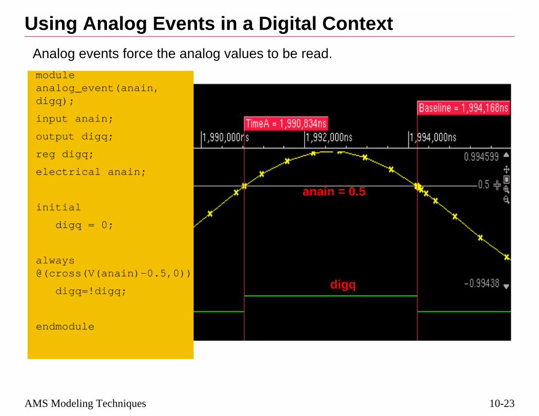
10-23
AMS Modeling TechniquesUsing Analog Events in a Digital ContextAnalog events force the analog values to be read.
moduleanalog_event(anain,digq);
input anain;
output digq;
reg digq;
electrical anain;
initial
digq = 0;
always@(cross(V(anain)-0.5,0))
digq=!digq;
endmodule
anain = 0.5
digq

10-24
Using Analog Events in a Digital Context
ontext, the analoge tick less than or
3/10/05 Virtuoso AMS Designer
■ When triggering on an analog event (cross, timer) in the digital cevent is evaluated in the digital context at the largest digital timequal to the analog time point where the event happened.
■ Synchronization comes after the @cross point.

10-25
ctability without
AMS Modeling Techniques
Review1. What is the best way to improve the analog signal predi
adding a lot of extra processing steps?

10-26
Review
3/10/05 Virtuoso AMS Designer
1. Use a transition filter.

10-27
AMS Modeling TechniquesLabs
Lab 10-1 AMS Modeling Techniques

10-28
3/10/05 Virtuoso AMS Designer
®
March 10, 2005
Module 11
11 VHDL-AMS ntation
Impleme
11-2
3/10/05 Virtuoso AMS Designer
11-3
VHDL-AMS ImplementationTopics in this Module■ VHDL-AMS background
■ Current VHDL-AMS implementation
■ Current VHDL-AMS use model

11-4
VHDL-AMS Implementation
3/10/05 Virtuoso AMS Designer

11-5
cription and
nical components,HDL
e non-digital
tems were required
VHDL-AMS Implementation
The Need for VHDL-AMS■ VHDL (IEEE STD 1076-1993) is widely used for the des
simulation of digital systems
■ Many real systems also include both analog and mechawhich cannot be fully described or modeled just using V
■ VHDL is not suitable for validation of systems that includcomponents
■ Enhancements to VHDL for analog and mixed-signal sys

11-6
The Need for VHDL-AMS
3/10/05 Virtuoso AMS Designer

11-7
s for specification,at different
behavioral and
AE)
VHDL-AMS Implementation
Domains in VHDL-AMS■ Discrete Domain: Structural and behavioral description
modeling, simulation and synthesis of discrete systems abstraction levels
■ Continuous Domain: Additional support for continuousstructural descriptions
❏ Models based on Differential Algebraic Equations (D
❏ Handling of initial conditions
❏ Piecewise defined behavior
❏ Discontinuities
❏ Conservative and Non-Conservative Semantics

11-8
Domains in VHDL-AMS
3/10/05 Virtuoso AMS Designer
■ Conservative: models physical systems
■ Non-conservative: models signal-flow, or S-domain

11-9
tity)
ior (architecture)
nd continuous
VHDL-AMS Implementation
VHDL-AMS Mixed-Signal DomainMixed-Signal Domain:
■ Analog and digital ports on one and the same model (en
■ A model can contain mixed-signal descriptions of behav
■ The LRM provides for:
❏ Synchronization mechanism between event-driven abehavior
❏ Mixed-signal initialization
❏ Mixed-signal simulation cycle

11-10
VHDL-AMS Mixed Signal Domain
in the LRM than it
ed in the LRM forod for
3/10/05 Virtuoso AMS Designer
■ The synchronization mechanism is described even more clearlywas for Verilog-AMS
■ Initialization is defined in the VHDL-AMS LRM. It wasn’t definVerilog-AMS, but Virtuoso® AMS Designer uses the same methVerilog-AMS.

11-11
ixed-signal
VHDL-AMS Implementation
VHDL-AMS Extensions to VHDL (Digital)If I know VHDL already, what was added?
Object Types: new objects and types
Environment: new attributes
Behavior: new statements
Structure: new interface objects
Simulation Cycle: an additional analog solver, new msimulation cycle

11-12
VHDL-AMS Extensions to VHDL (digital)
3/10/05 Virtuoso AMS Designer
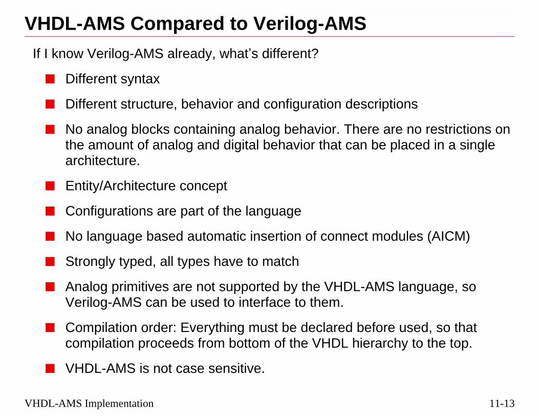
11-13
ns
no restrictions onaced in a single
ules (AICM)
language, so
used, so thaty to the top.
VHDL-AMS Implementation
VHDL-AMS Compared to Verilog-AMSIf I know Verilog-AMS already, what’s different?
■ Different syntax
■ Different structure, behavior and configuration descriptio
■ No analog blocks containing analog behavior. There arethe amount of analog and digital behavior that can be plarchitecture.
■ Entity/Architecture concept
■ Configurations are part of the language
■ No language based automatic insertion of connect mod
■ Strongly typed, all types have to match
■ Analog primitives are not supported by the VHDL-AMS Verilog-AMS can be used to interface to them.
■ Compilation order: Everything must be declared before compilation proceeds from bottom of the VHDL hierarch
■ VHDL-AMS is not case sensitive.

11-14
VHDL-AMS Compared to Verilog-AMS
lementation, of
3/10/05 Virtuoso AMS Designer
■ The Entity defines the interface; the architecture defines the impwhich there can be several that can be bound to the entity.

11-15
step NCSim
time
time
VHDL-AMS Implementation
VHDL-AMS Simulation FlowVHDL-AMS behavioral models are simulated using the three-simulation flow, just like Verilog-AMS models.
ncvhdl -ams -use5x vco.vhd
ncelab vco
ncsim -amslic vco -gui -analogcontrol vco.scsv
SPECTRE
SPICE
VERILOG-AMS
VHDL-AMS
Compile Elaborate
AMS Simulator
ContinuousTime Simulation
Engine
DiscreteEvent Simulation
Engine

11-16
VHDL-AMS Simulation Flow
ly digital
ell:view directoryame name as the
3/10/05 Virtuoso AMS Designer
■ For the ncvhdl command,
❑ The -ams option invokes the AMS parser, as opposed to pure
❑ The -use5x option compiles the VHDL-AMS unit into a lib.cstructure for use with the Hierarchy Editor. The cell has the sentity, and the view has the same name as the architecture.

11-17
Designertiate components
en in a different
VHDL-AMS Implementation
Instantiating VHDL-AMS in Virtuoso AMS ■ One common structural representation is used to instan
from different languages for simulation.
■ The following example shows three inverters, each writtlanguage being combined into a ring oscillator.
❏ The format of the instantiation statements is:modelname_instantiationname_connections
module ringOscillator ()spectre_inv INV1 (a,b);verilogams_inv INV2 (b,c);vhdlams_inv INV3 (c,a);
endmodule
INV1 INV2 INV3
a
b c

11-18
VHDL-AMS Instantiation in AMS Designer
3/10/05 Virtuoso AMS Designer
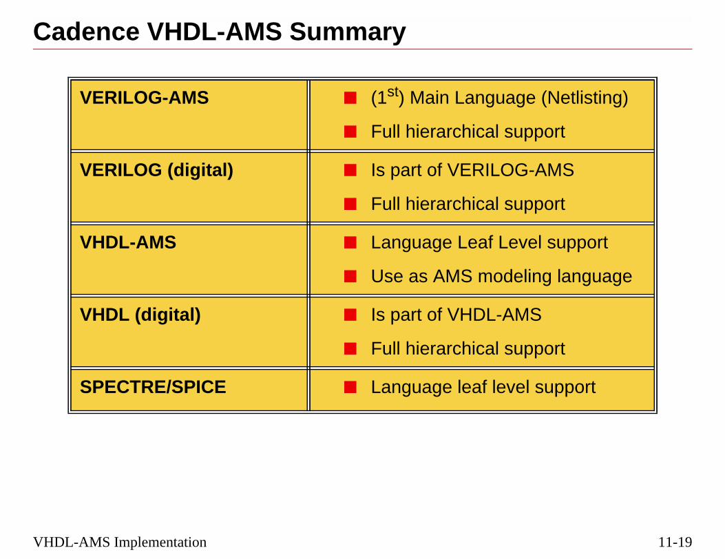
11-19
(Netlisting)
ort
MS
ort
l support
g language
ort
upport
VHDL-AMS Implementation
Cadence VHDL-AMS Summary
VERILOG-AMS ■ (1st) Main Language
■ Full hierarchical supp
VERILOG (digital) ■ Is part of VERILOG-A
■ Full hierarchical supp
VHDL-AMS ■ Language Leaf Leve
■ Use as AMS modelin
VHDL (digital) ■ Is part of VHDL-AMS
■ Full hierarchical supp
SPECTRE/SPICE ■ Language leaf level s

11-20
Cadence VHDL-AMS in the First Release
3/10/05 Virtuoso AMS Designer

11-21
nal modelingis the other).
netlisting from theerilog-AMS is kept
e VHDL-AMSog-AMS CMs.
VHDL-AMS Implementation
VHDL-AMS Current Implementation■ Use VHDL-AMS as a Mixed-Signal Modeling language.
❏ VHDL-AMS can be used as a second true mixed siglanguage for Virtuoso® AMS Designer (Verilog-AMS
❏ VHDL-AMS is not used as the language for standardschematic editor in Cadence® Design Framework II. Vas the language for netlisting.
■ Connect Modules (interface elements) are not part of thlanguage, but are inserted by AMS Designer using Veril

11-22
VHDL-AMS Current Implementation
3/10/05 Virtuoso AMS Designer

11-23
nguage portion
ities/architectures
such as: NOW,OVE, 'DELAYED,
definitions
VHDL-AMS Implementation
VHDL-AMS Supported Features■ Full coverage of VHDL (digital) language subset
❏ Same simulation speed as NCSim/ NCVHDL
■ Coverage of most commonly used syntax of the AMS la
❏ Support of analog/digital statement mix inside of ent
❏ Supports mix of structural and behavioral content
❏ Uses standard VHDL math operators and attributes,BREAK, IF/USE, 'DOT, 'INTEG, 'RAMP, 'SLEW, 'AB'LTF and many others
❏ Can have multiple Natures and user-defined Nature

11-24
VHDL-AMS Supported Features
3/10/05 Virtuoso AMS Designer
■ LTF stands for LaPlace Transform
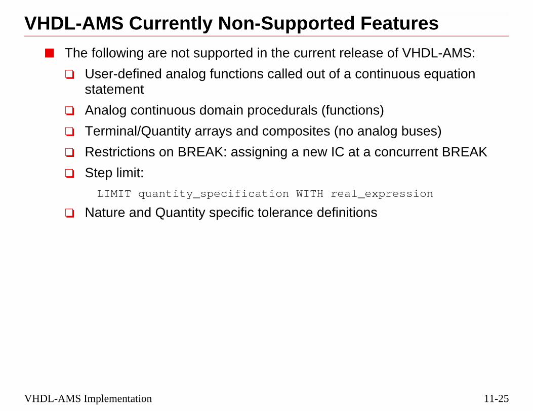
11-25
uresf VHDL-AMS:
ous equation
buses)
current BREAK
ssion
VHDL-AMS Implementation
VHDL-AMS Currently Non-Supported Feat■ The following are not supported in the current release o
❏ User-defined analog functions called out of a continustatement
❏ Analog continuous domain procedurals (functions)
❏ Terminal/Quantity arrays and composites (no analog
❏ Restrictions on BREAK: assigning a new IC at a con
❏ Step limit:
LIMIT quantity_specification WITH real_expre
❏ Nature and Quantity specific tolerance definitions

11-26
VHDL-AMS Currently Non-Supported Features
3/10/05 Virtuoso AMS Designer

11-27
FII
generation
MS language)
VHDL-AMS Implementation
VHDL-AMS Environment Support Within D■ VHDL-AMS view type
❏ Create, Edit, Compile, Cellview to Cellview, Symbol
■ Netlisting of VHDL-AMS view instantiations (in Verilog-A
❏ Check for VHDL-AMS reserved keywords
■ VHDL-AMS support of the Hierarchy editor
❏ Compilation, Compile Order, Configuration

11-28
VHDL-AMS Environment Support Within DFII
3/10/05 Virtuoso AMS Designer

11-29
he -use5x option
tity name must bee, it must be
ill be as many
und by the search
VHDL-AMS Implementation
VHDL-AMS DFII Cell ViewsIn DFII, the design units must be in lib.cell:view structure, so tmust be used while compiling.
■ The Cell name is the same as the Entity name.
❏ There can be only one Entity per cell.
❏ If the cell name is mixed case or capital case, the Enexactly the same. To keep any uppercase in the namescaped with slashes as follow:
/ChargePump/
■ Each architecture corresponds to a View name.
❏ If a file with several architectures is compiled, there wviews created as architectures.
❏ The architecture name must be in the view list to be fomechanism.

11-30
VHDL-AMS DFII Cell Views
3/10/05 Virtuoso AMS Designer

11-31
ts, such as mathare supplied for
sing an INCLUDE
ude the IEEE
vhdlams/cds.lib
er of the
y
VHDL-AMS Implementation
VHDL-AMS LibrariesCompiled units are stored in libraries.
■ Pre-defined libraries (e.g., IEEE) of standard design unifunctions, universal constants, or logic level definitions, reference in a model.
■ To use a library, it must be referenced in the cds.lib file uor SOFTINCLUDE statement.
❏ Adding the following to the project cds.lib file will inclVHDL-AMS libraries.
INCLUDE <IUS_install>/tools/inca/files/IEEE_
■ To make a library visible, it must be included in the headVHDL-AMS file:
library IEEE; -- pre-defined reference library
library WORK; -- standard name for a user librar

11-32
VHDL-AMS Libraries
iled using the
3/10/05 Virtuoso AMS Designer
During install, the IEEE VHDL-AMS standard libraries must be compfollowing script:<IUS_install>/tools/inca/files/install/ncvhdl.ins

11-33
:
rical natures
e basic constants
USE clause in the
es for analog
pes and levels
ge for shared use
th packages,
VHDL-AMS Implementation
VHDL-AMS Packages■ VHDL-AMS packages added to the IEEE library include
package IEEE.ELECTRICAL_SYSTEMS -- defines elect
package IEEE.ENERGY_SYSTEMS
package IEEE.FLUIDIC_SYSTEMS
package IEEE.MECHANICAL_SYSTEMS
package IEEE.RADIANT_SYSTEMS
pacakge IEEE.THERMAL_SYSTEMS
package IEEE.FUNDAMENTAL_CONSTANTS -- defines som
package IEEE.MATERIAL_CONSTANTS
■ To use a package within the library, it must be called by aheader of a VHDL-AMS file, as follows:
USE IEEE.electrical_systems.all;-- defines natur
USE IEEE.std_logic_1164.all; -- defines logic ty
USE WORK.std_decls.all; -- a user-generated packa
■ Virtuoso AMS Designer supports the standard IEEE maMATH_REAL and MATH_COMPLEX.

11-34
VHDL-AMS Packages
nd are not yetat the definitions
rc/
3/10/05 Virtuoso AMS Designer
■ The VHDL-AMS packages listed above are still in draft form, areleased IEEE standards. For more information about them, lookin:
<IUS_install_path>/tools/inca/files/IEEE_vhdlams.s
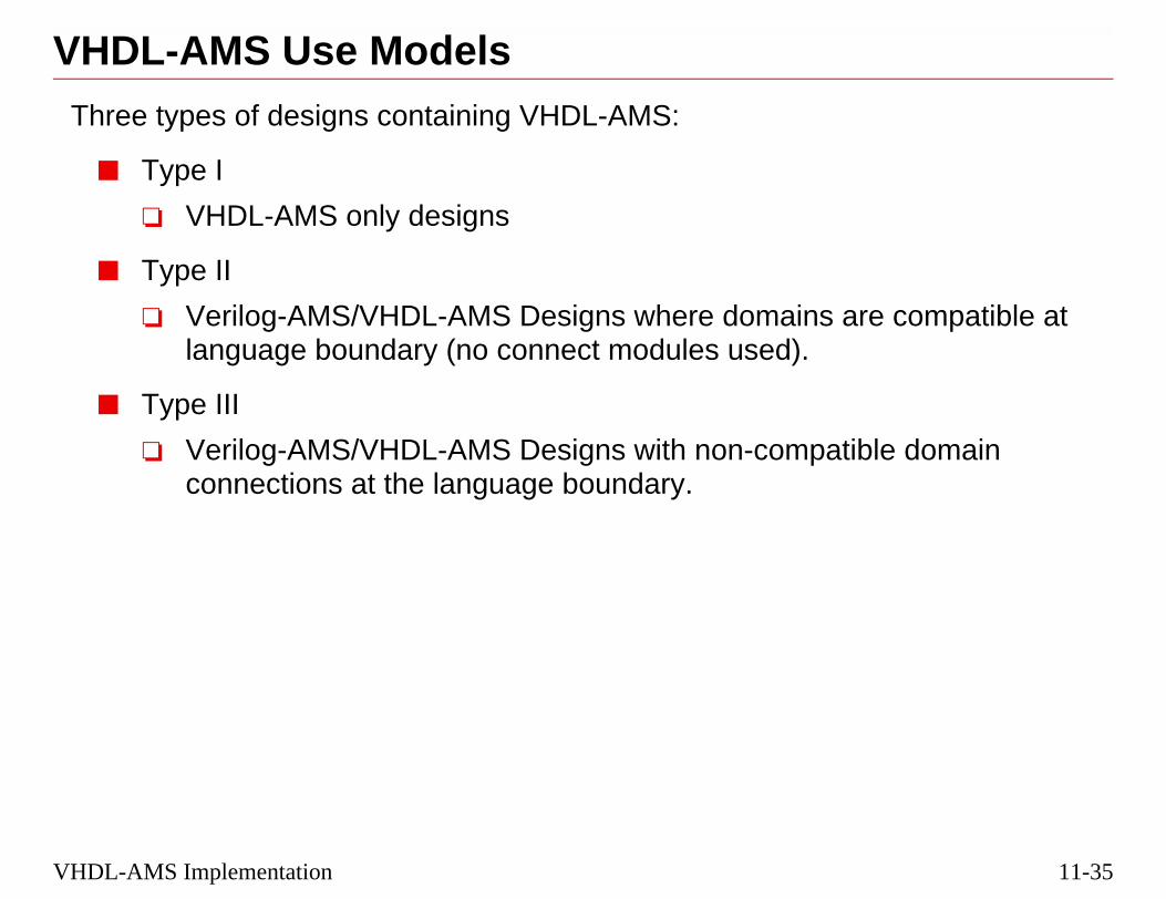
11-35
e compatible at
le domain
VHDL-AMS Implementation
VHDL-AMS Use ModelsThree types of designs containing VHDL-AMS:
■ Type I
❏ VHDL-AMS only designs
■ Type II
❏ Verilog-AMS/VHDL-AMS Designs where domains arlanguage boundary (no connect modules used).
■ Type III
❏ Verilog-AMS/VHDL-AMS Designs with non-compatibconnections at the language boundary.

11-36
VHDL-AMS Use Models
Hierarchy Editor.
3/10/05 Virtuoso AMS Designer
■ Type III might occur most readily when switching views in the

11-37
VHDL-AMS ImplementationVHDL-AMS Type I DesignsType I: VHDL-AMS only
■ Full hierarchical support of VHDL-AMS and/or VHDL
■ Full VHDL language feature support
■ Major VHDL-AMS features supported (see previous list)
■ VHDL-AMS supported as defined by the LRM

11-38
VHDL-AMS Type I Designs
3/10/05 Virtuoso AMS Designer

11-39
le)
S or VHDL
ible (Type I)
MS port
r (electrical =
= quantity voltage)erilog-AMSpported.
VHDL-AMS Implementation
VHDL-AMS Type II DesignsType II: Verilog-AMS/VHDL-AMS Designs (domains compatib
■ Verilog-AMS must be on top and instantiates VHDL-AM
❏ Hierarchy inside Verilog-AMS possible
❏ Hierarchy inside instantiated VHDL/VHDL-AMS poss
■ General requirements at the language boundaries:
❏ Discrete Verilog-AMS connected to discrete VHDL-A(i.e., logic = std_logic, wreal = real)
❏ Continuous Conservative ports connect to each otheelectrical)
❏ Continuous Non-Conservative (i.e., discipline voltageport connection support is restricted. For example, Vconnections to VHDL-AMS Quantity ports are not su

11-40
VHDL-AMS Type II Designs
3/10/05 Virtuoso AMS Designer

11-41
patible)
S or VHDL (same
logic port will haverical net and the
trical port will havelogic port and the
ve the proper
sing automatically
e same as Type II.
VHDL-AMS Implementation
VHDL-AMS Type III DesignsType III: Verilog-AMS/VHDL-AMS Designs (domains not com
■ Verilog-AMS must be on top and instantiates VHDL-AMas Type II)
■ VHDL port natures determine attached net disciplines.
❏ A VHDL-AMS electrical port connecting to a Verilogan E2L CM automatically inserted between the electVerilog logic port.
❏ A VHDL logic port connecting to a Verilog-AMS elecan L2E CM automatically inserted between the VHDLelectrical net.
❏ VHDL-AMS analog ports to VHDL digital ports will haConnect Module inserted.
■ Spectre/SPICE primitives will connect to VHDL-D ports uinserted CMs.
■ General requirements at the language boundaries are th
11-42
VHDL-AMS Type III Designs
3/10/05 Virtuoso AMS Designer

11-43
insct Modules are
rts of VHDL-AMS and an L2E CM
rts of VHDL-AMS and an E2L CM
Verilog-AMS
Automatically
Verilog-AMS
Automatically
VHDL-AMS Implementation
Connect Module Insertion on Mixed DomaThe following domain connection examples show how Conneinserted:
■ Verilog-AMS domain-less wires connected to digital poinstances are forced automatically to electrical disciplineinserted.
■ Verilog-AMS domain-less wires connected to analog poinstances are forced automatically to electrical disciplineinserted.
VHDL-AMS std_logic electricalelectrical
L2E Connect Module Inserted
VHDL-AMS logicelectrical
E2L Connect Module Inserted
electrical

11-44
Connect Module Insertion on Mixed Domains
3/10/05 Virtuoso AMS Designer
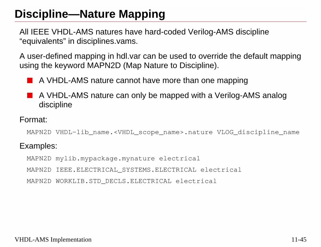
11-45
iscipline
default mapping
ing
-AMS analog
discipline_name
l
VHDL-AMS Implementation
Discipline—Nature MappingAll IEEE VHDL-AMS natures have hard-coded Verilog-AMS d“equivalents” in disciplines.vams.
A user-defined mapping in hdl.var can be used to override theusing the keyword MAPN2D (Map Nature to Discipline).
■ A VHDL-AMS nature cannot have more than one mapp
■ A VHDL-AMS nature can only be mapped with a Verilogdiscipline
Format:
MAPN2D VHDL-lib_name.<VHDL_scope_name>.nature VLOG_
Examples:
MAPN2D mylib.mypackage.mynature electrical
MAPN2D IEEE.ELECTRICAL_SYSTEMS.ELECTRICAL electrica
MAPN2D WORKLIB.STD_DECLS.ELECTRICAL electrical

11-46
Discipline - Nature Mapping
3/10/05 Virtuoso AMS Designer
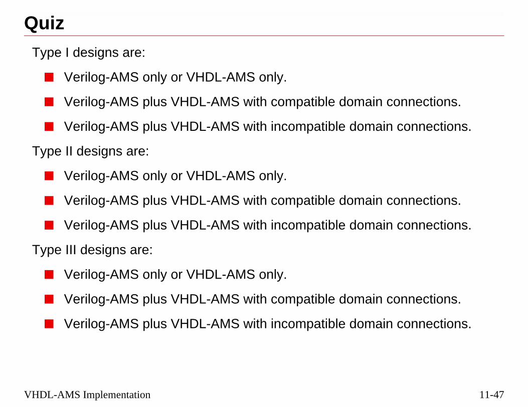
11-47
onnections.
connections.
onnections.
connections.
onnections.
connections.
VHDL-AMS Implementation
QuizType I designs are:
■ Verilog-AMS only or VHDL-AMS only.
■ Verilog-AMS plus VHDL-AMS with compatible domain c
■ Verilog-AMS plus VHDL-AMS with incompatible domain
Type II designs are:
■ Verilog-AMS only or VHDL-AMS only.
■ Verilog-AMS plus VHDL-AMS with compatible domain c
■ Verilog-AMS plus VHDL-AMS with incompatible domain
Type III designs are:
■ Verilog-AMS only or VHDL-AMS only.
■ Verilog-AMS plus VHDL-AMS with compatible domain c
■ Verilog-AMS plus VHDL-AMS with incompatible domain

11-48
Quiz
3/10/05 Virtuoso AMS Designer

11-49
dule Insertion
VHDL-AMS Implementation
Lab
Lab 11-1 Type III Mixed-Signal, Mixed-Domain Connect Mo

11-50
Lab
3/10/05 Virtuoso AMS Designer

®
March 10, 2005
Module 12
®
Module 12
12 Introductio HDL-AMS Language
n to the V
12-2
3/10/05 Virtuoso AMS Designer
12-3
Introduction to the VHDL-AMS LanguageTopics in this Module■ The VHDL-AMS language

12-4
Introduction to the VHDL-AMS Language
3/10/05 Virtuoso AMS Designer

12-5
1076-1993)
andard document:
re still valid in
Introduction to the VHDL-AMS Language
Origins of the VHDL-AMS Language■ VHDL-AMS is based on the VHDL standard (IEEE STD
■ VHDL-AMS is defined in the extended version of 1076 st1076.1-1999
■ VHDL-AMS does not redefine VHDL: all VHDL models aVHDL-AMS
■ VHDL-AMS becomes a superset of the VHDL language

12-6
Origins of the VHDL-AMS Language
allation document
erson, and
3/10/05 Virtuoso AMS Designer
■ A Cadence VHDL-AMS Overview is provided in the IUS53 instdirectory, and can be viewed from CDSDoc.
■ A recent book on the subject of VHDL-AMS is:
The System Designer’s Guide to VHDL-AMS, by Ashenden, PetTeegarden, Morgan Kaufmann Publishers, 2003

12-7
to two major partsarchy:
onent
Introduction to the VHDL-AMS Language
VHDL-AMS Designs■ Just like VHDL (digital), a VHDL-AMS design is divided in
to form a component which can be instantiated in a hier
❏ Entity declaration with ports and generics.
❏ Architecture body with behavior and structure.
Entity Declaration
Architecture Body
VHDL-AMS Design(Model/Netlist)
Comp

12-8
VHDL-AMS Designs
3/10/05 Virtuoso AMS Designer

12-9
some similarities.
;;;
k`event and clk=‘1’));
Introduction to the VHDL-AMS Language
VHDL vs. Verilog■ The structure of Verilog® and VHDL modules/units have
//reg1.vlog
module reg1 ( datao , datai , clk , rst );
output datao ;input datai ;input clk ;input rst ;reg datao ;
always begin @(posedge clk or posedge rst) if (rst == 1) datao <= 0; else datao <= datai; end
endmodule
//reg1.vhdl
library ieee;use ieee.std_logic_1164.all;
entity reg1 is port ( datao : out std_logic datai : in std_logic clk : in std_logic rst : in std_logic );end reg1;
architecture vhdl of reg1 is
begin
process begin wait until (rst=‘1’ or (cl if (rst = ‘1’) then datao <= ‘0’; else datao <= datai; end if; end process;
end vhdl;
Verilog VHDL
PortDeclarations
Behavior

12-10
VHDL vs. Verilog
3/10/05 Virtuoso AMS Designer

12-11
erics
ich can be passed
Introduction to the VHDL-AMS Language
VHDL-AMS Entity Declarations■ The ENTITY describes the interface, with ports and gen
■ General format:
ENTITY inverter IS
PORT (a : IN std_logic;
y : OUT std_logic);
GENERIC (tdelay : TIME);
END inverter;
■ Ports can be:
❏ Signal ports (digital)
❏ Terminal ports (analog - conservative)
❏ Quantity ports (analog - non-conservative)
■ Ports are assigned:
❏ Direction (in, out, inout)
❏ Type (bit, std_logic)
■ Generics are the parameters used in the architecture, whvalues from the calling unit

12-12
VHDL-AMS Entity Declarations
gn and the more than onesame interface.
k and its, quantities, or
a block statement,ide a channel fornment. Unlike
3/10/05 Virtuoso AMS Designer
■ An entity is the definition of the interface between a given desienvironment in which it is used. A given entity can be shared bydesign, each of which has a different architecture, but share the
■ A port is a channel for dynamic communication between a blocenvironment. Ports are declared in the entity, and can be signalsterminals.
■ A generic is an interface constant declared in the block header ofa component declaration, or an entity declaration. Generics provstatic information to be communicated to a block from its enviroconstants, the value of a generic can be supplied externally.

12-13
e VHDL design
one during
Introduction to the VHDL-AMS Language
VHDL-AMS Architecture Body■ An architecture describes the structure or behavior of th
entity.
❏ There can be several architectures for each entity.
❏ Binding a particular architecture to an entity can be dinstantiation.
❏ The entity must be compiled before the architecture.
■ General form:ARCHITECTURE my_inverter OF inverter IS
BEGIN
y <= NOT a AFTER tdelay;
END my_inverter;
■ Architectures contain:
❏ Constants, variables, and internal signal declarations
❏ Component instantiations
❏ Structure
❏ Behavior

12-14
VHDL-AMS Architecture Body
nal organization orcribe the behavior,
ignals, quantities,
s must be declared
nt interconnection
ust be declared
3/10/05 Virtuoso AMS Designer
■ An architecture is associated with an entity to describe the interoperation of a design. The body of the architecture is used to desdata flow, or structure of a design entity.
■ A component describes an instance of an entity, and connects sand terminals to the ports of the instance.
■ A constant is an object whose value cannot be changed. Constantbefore being used in models.
■ A signal is an object with a past history of values. Signals represewires.
■ A variable is an object with a single current value. Variables mbefore being used in a model.

12-15
MShavior is based ontwo or more
ies
MINAL
ating point values
signals, as in
Introduction to the VHDL-AMS Language
Description of Analog Behavior in VHDL-A■ The description of continuous (as opposed to discrete) be
Differential Algebraic Expressions (DAEs), which relate continuous quantities.
❏ General form: f1(p,q) + f2(p,q) = 0
❏ Simple example: Ohm’s Law
V == I * R; where I and V are continuous quantit
■ Two new objects added to VHDL: QUANTITY and TER
❏ Quantities are continuous system variables having floand represent the unknowns in the DAEs.
❏ Terminals are the connection points between analognodes or ports.
■ VHDL-AMS provides support for:
❏ Conservative systems (e.g., Kirchhoff’s Laws).
❏ Time domain and frequency domain simulations.

12-16
Description of Analog Behavior in VHDL-AMS
L-AMS and allow
st likeNon-conservative
n Signal Flow
sis.
3/10/05 Virtuoso AMS Designer
■ Terminals, quantities, and reference terminals are new for VHDfor analog interconnects, signals, and values.
■ Conservative systems define both ACROSS and THROUGH, juVerilog-AMS conservative natures have both potential and flow.systems define only one of those attributes, and are often used ianalysis.
■ Virtuoso® AMS Designer currently supports only transient analy

12-17
Introduction to the VHDL-AMS LanguageBasic Constructs in VHDL-AMS
NATURE Q'ABOVE
TERMINAL Q'DELAYED
QUANTITY Q'INTEG
ACROSS Q'DOT
THROUGH Q'SLEW
S'RAMP
BREAK

12-18
Basic Constructs in VHDL-AMS
3/10/05 Virtuoso AMS Designer

12-19
S
ain.
ture)
te)
ties incident to the
nd.
natures (records,
Introduction to the VHDL-AMS Language
Natures in VHDL-AMS■ A nature in VHDL-AMS is like a discipline in Verilog-AM
■ A nature represents a physical discipline or energy dom
❏ Electrical and non-electrical disciplines
■ A nature has two aspects related to physical effects.
❏ across: effort-like effects (voltage, velocity, tempera
❏ through: flow-like effects (current, flow, heat flow ra
■ A nature defines the types of across and through quantiterminal of the nature.
■ Natures are also defined by a reference terminal or grou
■ Natures may be grouped together to provide compositearrays).

12-20
Natures in VHDL-AMS
a package.
and I in
3/10/05 Virtuoso AMS Designer
■ Natures, such as “electrical” may be pre-defined and supplied in
■ ACROSS and THROUGH are similar to the access functions VVerilog-AMS.

12-21
I
R
Introduction to the VHDL-AMS Language
Defining Natures in VHDL-AMSElectrical Nature example:
SUBTYPE voltage is REAL;SUBTYPE current is REAL;
NATURE electrical ISvoltage ACROSScurrent THROUGHground REFERENCE;
V

12-22
Defining Natures in VHDL-AMS
which is thenport this type of” as the reference.
3/10/05 Virtuoso AMS Designer
■ The proposed IEEE standard calls the reference “electrical_ref,”aliased to “ground.” The Virtuoso AMS Simulator does not supalias, so the library that defines the electrical nature has “ground
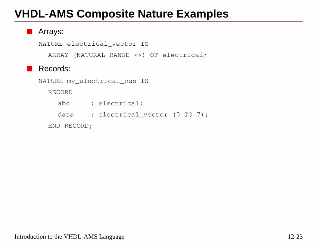
12-23
Introduction to the VHDL-AMS LanguageVHDL-AMS Composite Nature Examples■ Arrays:
NATURE electrical_vector IS
ARRAY (NATURAL RANGE <>) OF electrical;
■ Records:
NATURE my_electrical_bus IS
RECORD
abc : electrical;
data : electrical_vector (0 TO 7);
END RECORD;

12-24
VHDL-AMS Composite Nature Examples
rds).
3/10/05 Virtuoso AMS Designer
The current implementation does not support composites (arrays, reco
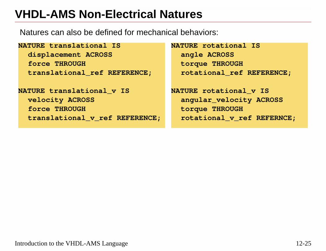
12-25
l IS
REFERENCE;
l_v ISty ACROSS
ef REFERNCE;
Introduction to the VHDL-AMS Language
VHDL-AMS Non-Electrical NaturesNatures can also be defined for mechanical behaviors:
NATURE translational ISdisplacement ACROSSforce THROUGHtranslational_ref REFERENCE;
NATURE translational_v ISvelocity ACROSSforce THROUGHtranslational_v_ref REFERENCE;
NATURE rotationaangle ACROSStorque THROUGHrotational_ref
NATURE rotationaangular_velocitorque THROUGHrotational_v_r

12-26
VHDL-AMS Non-Electrical Natures
3/10/05 Virtuoso AMS Designer

12-27
continuous signals.
nodes of a system.
ergy rules apply.
through types for
d.
Introduction to the VHDL-AMS Language
VHDL-AMS Terminals■ TERMINALS are a new object in VHDL 1076. 1 used for
❏ They provide the physical connection points or circuit
■ TERMINALS belong to a nature and conservation of en
❏ The nature of the terminal determines the across andthe terminal.
■ Branch quantities between the terminals can be declare
■ There are two types of terminals
❏ Terminal Ports (for entity interfaces)
❏ Terminal Declarations (within an architecture)

12-28
VHDL-AMS Terminals
mplicitly creating quantity (also to
as a continuous
iven nature as thel natures.
3/10/05 Virtuoso AMS Designer
■ A terminal is a point of physical connection between devices, iboth an across quantity (to the reference terminal) and a throughthe reference terminal).
■ A quantity is an object with a floating point value, and which hsolution set by the analog solver.
■ The reference terminal is a terminal used by all terminals of a gzero for the values of its across type, i.e., “ground” for electrica

12-29
e in the body of the
e them appear in
TO cathode;
Introduction to the VHDL-AMS Language
VHDL-AMS Terminal Declarations■ A terminal can be used to declare an internal analog nod
Architecture.
❏ Terminal declarations and the quantities that describthe architecture body before the BEGIN keyword.
ARCHITECTURE ideal OF system IS
TERMINAL anode, cathode : ELECTRICAL;
QUANTITY batt_v ACROSS batt_i THROUGH anode
...
BEGIN
... -- architecture body
...
END ARCHITECTURE

12-30
VHDL-AMS Terminal Declarations
3/10/05 Virtuoso AMS Designer
“--” marks out comments in VHDL code

12-31
represent a circuit
as signal ports,or signal ports.
entities using
anode
cathode
Introduction to the VHDL-AMS Language
VHDL-AMS Terminal Ports■ Terminals are used to declare ports in the Entity.
❏ Terminal ports are the analog ports in an entity. Theynode having an electrical nature.
❏ Terminal ports are implemented much the same wayexcept the keyword terminal is not optional, as it is f
❏ Terminal ports must belong to a defined nature type.
❏ Terminal ports represent the interconnects between conservative modeling techniques.
LIBRARY ieee, DISCIPLINES;USE DISCIPLINES.electrical_sys.all;ENTITY diode IS
PORT (TERMINAL anode, cathode : electrical);
END ENTITY diode;

12-32
VHDL-AMS Terminal Ports
3/10/05 Virtuoso AMS Designer

12-33
senting a voltage
properties of the
ms
Introduction to the VHDL-AMS Language
VHDL-AMS QuantitiesVHDL-AMS defines 3 different types of Quantities
■ Free quantities
❏ an analog-valued object used in signal-flow modeling
❏ can be associated with analog quantity ports – reprelevel that is continuous with time
■ Branch quantities
❏ constrained by the values of the voltage and currentassociated terminal
❏ specifically used to model conservative energy syste
❏ through and across reference required
■ Source quantities
❏ defined as scalar or composites
❏ used for frequency and noise modeling

12-34
VHDL-AMS Quantities
d signals in a
3/10/05 Virtuoso AMS Designer
■ QUANTITIES are the unknowns in an expression, like nodes ancircuit.
■ Source quantities are not currently supported.

12-35
lue is determined
g to conservative
p together similarce requirements
Introduction to the VHDL-AMS Language
VHDL-AMS Free Quantities■ A free quantity is not constrained by any terminal. Its va
solely by the equations in the model.
■ A free quantity is defined as a scalar or composite
■ A free quantity can be used in equations without adherinenergy laws
QUANTITY isense : current;
QUANTITY power : REAL TOLERANCE “power”;
■ Note the tolerance is a string which may be used to grouquantities which may have similar accuracy and toleran
■ Quantities may have an initial value assigned.
QUANTITY q1 : REAL := 3.5;

12-36
VHDL-AMS Free Quantities
3/10/05 Virtuoso AMS Designer
Tolerance currently uses a default value.

12-37
signal port except
.
n entity instances
Introduction to the VHDL-AMS Language
VHDL-AMS Quantity Ports■ Quantity Ports are implemented much the same way as a
the keyword quantity is not optional.
ENTITY adc IS
PORT ( QUANTITY gain : IN VOLTAGE;
... );
END ENTITY adc;
■ The mode can only be in or out. The default mode is in
■ Allows for the representation of interconnections betweeusing non-conservative modeling techniques.

12-38
VHDL-AMS Quantity Ports
3/10/05 Virtuoso AMS Designer
Currently, there is no support for an array of quantities.

12-39
reference terminal
de;
ween terminals
me terminals have
urrents in the twoe to terminal
same terminals
s and minus
als of a branch
Introduction to the VHDL-AMS Language
VHDL-AMS Branch Quantities■ Declared between two terminals: plus and minus
❏ If only one terminal given, minus terminal defaults toof nature.
QUANTITY vd ACROSS id, ic THROUGH anode TO catho
QUANTITY v1 ACROSS i1 THROUGH vout;
■ vd is an ACROSS quantity: it represents the voltage betanode and cathode (vd = v_anode - v_cathode).
❏ Multiple ACROSS quantities declared between the sathe same value.
■ id and ic are THROUGH quantities: they represent the cparallel branches. Both currents flow from terminal anodcathode.
❏ Multiple THROUGH quantities declared between thedefine parallel branches.
■ A branch quantity gets its type from the nature of its pluterminals.
❏ The scalar sub-element of the plus and minus terminquantity must belong to the same scalar nature.

12-40
VHDL-AMS Branch Quantities
ration.
d;
d;
3/10/05 Virtuoso AMS Designer
■ Anode and cathode must be pre-defined by a TERMINAL decla
■ Branch quantities may also be initialized:QUANTITY v1:=4.32 ACROSS i1 THROUGH t1 to groun
QUANTITY v1 ACROSS i1:=0.98 THROUGH t1 to groun

12-41
tial behavior. All
f the sequentialntil the condition of
nd signals, whose
ents.
st of example IS z : integer;
c, d;
Introduction to the VHDL-AMS Language
VHDL Processes■ VHDL and VHDL-AMS use processes to define sequen
other behavior within an architecture is concurrent.
■ Processes can have:
❏ A sensitivity list of signals that will trigger operation obehavior; or a WAIT statement that halts execution uthe wait is satisfied.
❏ Variables, which are assigned values immediately; avalues are only updated at the end.
❏ IF-THEN-ELSE, CASE, LOOP (FOR, WHILE) statem
architecture sensitivity_list of example issignals a, b, c, d, z : integer;
beginprocess (a,b,c,d)begin
z <= a+b;z <= c+d;
end process;end sensitivity_list;
architecture waitlisignal a, b, c,d,
beginprocessbegin
z <= a+b;z <= c+d;wait on a, b,
end process;end waitlist;

12-42
VHDL Processes
that are performedmultiple processes.
ated at the end of
execute only once.
3/10/05 Virtuoso AMS Designer
■ A process is the basic unit of execution in VHDL. All operationsin a simulation of a VHDL description are broken into single or
■ In both examples, because the values of the signals are only updthe process, z receives the value of c+d, not a+b.
■ With neither a sensitivity list or a wait statement, a process will

12-43
process or
ctor)
lay)
al delay)
Introduction to the VHDL-AMS Language
Using the WAIT StatementThe WAIT statement suspends the sequential execution of a subprogram until the condition clears.
■ WAIT ON — waits until a signal changes (an event dete
WAIT ON a,b;
■ WAIT FOR — waits a specific amount of time (a time de
WAIT FOR 10 ms;
■ WAIT UNTIL — waits until an expression is true (a logic
WAIT UNTIL clock = ‘1’ AND clock’EVENT;

12-44
Using the WAIT Statement
s in that sensitivity
3/10/05 Virtuoso AMS Designer
A PROCESS with a sensitivity list is an implicit WAIT ON (the signallist).
PROCESS (a, b, c)
has the same effect as:WAIT ON (a, b, c);
which would be placed just before the END PROCESS;

12-45
ntimultaneous
train the values of
.
nd reside in and.
sses in a single.
point, quantitiesof the “==” sign are
the bounds of theation.
Introduction to the VHDL-AMS Language
VHDL-AMS Simple Simultaneous Stateme■ Newly added VHDL-AMS syntax describing an analog s
statement is denoted by the “double equal” == signs
■ Specifies expressions used by the analog solver to consquantities rather than providing new values for objects.
■ No analog block required as in Verilog-AMS or Verilog-A
■ Simple simultaneous statements execute concurrently aarchitecture anywhere a concurrent statement is allowe
■ Simultaneous statements can be used along with procearchitecture to express both analog and digital behavior
■ The analog solver ensures that, at each analog solutiontake on values that ensure the expressions on each sideequal.
❏ Equality on each side of the “==” is determined withintolerance group that applies to the simultaneous equ

12-46
VHDL-AMS Simple Simultaneous Statement
or used in
ct on V(b).
(b). The two sides
3/10/05 Virtuoso AMS Designer
The Simultaneous Statement is different from the Contribution operatVerilog-AMS.
1. In the Verilog-AMS expression,V(a) <+ V(b) + 5.0;
what might happen to V(a) due to some other driver has no effe
2. In the VHDL-AMS expression,V(a) == V(b) + 5.0;
both sides must balance, so a change on V(a) will also change Vof the equation could be interchanged.

12-47
er 10 ns.
Introduction to the VHDL-AMS Language
Various Operators Using the Equal Sign■ Port or generic mapping, =>
U1:nand2 PORT MAP(a => set, b => qb, c => q);
GENERIC MAP (td => delay1);
■ Testing, =
IF a = ‘1’ THEN b <= ‘0’ AFTER 1 ns;
sel <= 0 WHEN a = ‘1’ and b = ‘0’;
■ Variable value assignment (instantaneous), :=
duty_cycle := dmin;
■ Concurrent assignment (digital), <=
a <= b; -- a gets the value of b
a <= b AFTER 10 ns; -- a gets the value of b aft
■ Analog simultaneous statements, ==
vout == vtemp’RAMP(tr,tf);

12-48
Various Operators Using the Equal Sign
3/10/05 Virtuoso AMS Designer

12-49
any equations as
ne equation.
CROSS quantities.
must equal the
vdc ISTHROUGH p TO m;
;
Introduction to the VHDL-AMS Language
VHDL-AMS Solvability Checks■ A necessary condition for solvability is that there be as m
unknowns in the models.
❏ Each (scalar) simultaneous statement (==) creates o
❏ An implicit equation is defined by the language for A
■ In a VHDL-AMS design entity, the number of equations number of:
❏ free quantities, plus the
❏ through quantities, plus the
❏ interface quantities with mode outENTITY vdc IS
GENERIC(dc : REAL := 1.0);PORT (TERMINAL p,m : electrical);
END ENTITY vdc;
ARCHITECTURE good OF QUANTITY v ACROSS i
BEGINv == dc;
END ARCHITECTURE good
ARCHITECTURE bad OF vdc ISQUANTITY v ACROSS p TO m;
BEGINv == dc;
END ARCHITECTURE bad;
BAD GOOD

12-50
VHDL-AMS Solvability Checks
itectures, but only that satisfies the
h quantity” needsere needs to be a
SCSUMM error
3/10/05 Virtuoso AMS Designer
■ In the example above, only one equation is defined in both archthe GOOD architecture has a declaration for a through quantitynumber requirement.
❑ Simplistically, if you have a simultaneous equation, a “througto be declared; or, if there is a “through quantity” declared, thsimultaneous equation.
■ If you have a solvability problem in a design, you will receive afrom ncvhdl_p.

12-51
Introduction to the VHDL-AMS LanguageVHDL-AMS Simple Resistor ExampleA simple resistor is modeled like this using VHDL-AMS:
ENTITY resistor IS
GENERIC (r : REAL := 1.0);
PORT (TERMINAL p, m : electrical);
END ENTITY resistor;
ARCHITECTURE my_resistor OF resistor IS
QUANTITY vr ACROSS ir THROUGH p TO m;
BEGIN
ir == vr/r;
END ARCHITECTURE my_resistor;

12-52
VHDL-AMS Simple Resistor Example
3/10/05 Virtuoso AMS Designer
If r could be set to 0, change the equation tovr == ir * r;
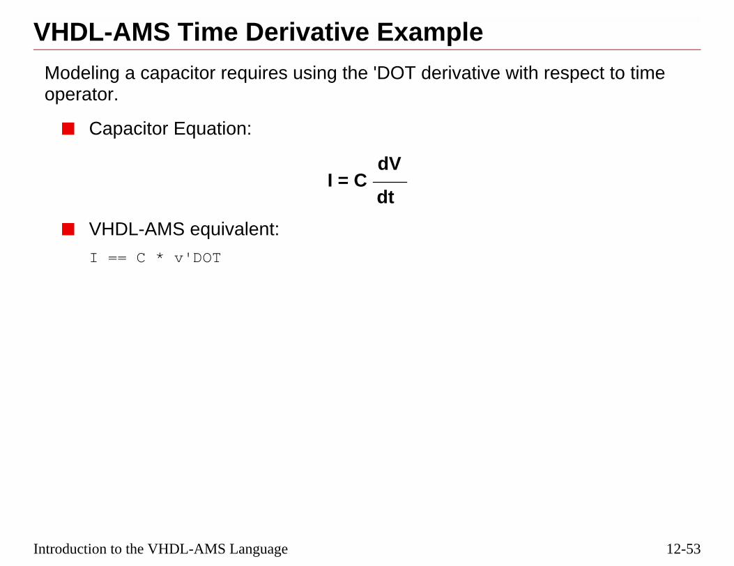
12-53
respect to time
Introduction to the VHDL-AMS Language
VHDL-AMS Time Derivative ExampleModeling a capacitor requires using the 'DOT derivative with operator.
■ Capacitor Equation:
■ VHDL-AMS equivalent:
I == C * v'DOT
I = CdV
dt

12-54
VHDL-AMS Time Derivative Example
3/10/05 Virtuoso AMS Designer
■ v'DOT'DOT would be the second derivative of v.

12-55
Introduction to the VHDL-AMS LanguageVHDL-AMS Simple Inductor ExampleA simple inductor model also uses a time derivative:
ENTITY inductor IS
GENERIC (L : REAL := 1.0e-12);
PORT (TERMINAL p, m : electrical);
END ENTITY inductor;
ARCHITECTURE my_inductor OF inductor IS
QUANTITY vi ACROSS ii THROUGH p TO m;
BEGIN
vi == L * ii'DOT;
END ARCHITECTURE my_inductor;

12-56
VHDL-AMS Simple Inductor Example
3/10/05 Virtuoso AMS Designer

12-57
EAK statement.
the beginning of a
the DAEs
terval
s
tity at some time Ty lead to erroneous
Introduction to the VHDL-AMS Language
Concurrent BREAK Statement■ Initial conditions can be specified with the concurrent BR
❏ For example: BREAK v => 0.0, s => 10.0;
❏ The initial condition for quantity v is 0.0; for s, 10.0
❏ An initial condition specifies the value of a quantity atcontinuous interval.
■ BREAK ON announces a discontinuity in the solution of
❏ Analog solver must re-initialize for next continuous in
■ BREAK ON event may include condition
❏ New initial conditions may be specified onto quantitie
■ If a VHDL-AMS model causes a discontinuity on a quanbut does not execute a BREAK statement at time T, it maresults.

12-58
Concurrent BREAK Statement
alog solution point
T == 0 while
= Q(-t) when
3/10/05 Virtuoso AMS Designer
■ Initial conditions replace implicit equations while finding the an
❑ An initial condition for Q replaces the implied equation Q'DOfinding the quiescent state.
❑ An initial condition for Q replaces the implied equations Q =re-initializing after a discontinuity.

12-59
for a PROCESSents and condition
ent.
(a list of signalnt in the equivalent.
‘1’ AND clk = ‘1’;
’;
Introduction to the VHDL-AMS Language
Concurrent BREAK Example■ A concurrent BREAK statement is a shorthand notation
containing a sequential BREAK with the same break elemclause.
❏ The sequential BREAK is followed by a WAIT statem
❏ If the concurrent BREAK includes a sensitivity clausenames following an ON keyword), the WAIT statemePROCESS would contain the same sensitivity clause
--Concurrent BREAK exampledischarge_cap : BREAK cap_charge => 0.0 ON clk WHEN discharge =
--Sequential BREAK exampledischarge_cap : PROCESS IS
BEGINBREAK cap_charge => 0.0 WHEN discharge = ‘1’ AND clk = ‘1WAIT ON clk;
END PROCESS discharge_cap;
Equivalent BREAKs

12-60
Concurrent BREAK Example
3/10/05 Virtuoso AMS Designer

12-61
own, as in this
Introduction to the VHDL-AMS Language
VHDL-AMS Initial Conditions ExampleInitial conditions can be set for t=0 if the value would be unknexample:
ENTITY capacitor IS
GENERIC (C : REAL; ic: REAL := 0.0);
PORT (TERMINAL p, m : electrical);
END ENTITY capacitor;
ARCHITECTURE my_capacitor OR capacitor IS
QUANTITY v ACROSS i THROUGH p TO m;
BEGIN
i == C * v’DOT;
BREAK v => ic;
-- ic replaces v’DOT at t=0
END ARCHITECTURE my_capacitor;

12-62
VHDL-AMS Initial Conditions Example
3/10/05 Virtuoso AMS Designer

12-63
ent parts based on
include any of the
piecewise
AK statements
he occurrence of
Introduction to the VHDL-AMS Language
VHDL-AMS Piecewise Defined Behavior■ The simultaneous IF statement selects one of the statem
the value of one or more of the conditions.
■ Each statement part of a simultaneous IF statement canfollowing simultaneous statements:
❏ Simple simultaneous statement
❏ Simultaneous IF statement
❏ Simultaneous CASE statement
❏ Simultaneous PROCEDURAL statement
■ The simulator can solve equations for quantities that arecontinuous provided we:
❏ Indicate the occurrences of discontinuities with BRE
❏ Provide new initial conditions at discontinuities
Important
VHDL-AMS requires the use of BREAK statements to explicitly indicate tdiscontinuities.

12-64
VHDL-AMS Piecewise Defined Behavior
3/10/05 Virtuoso AMS Designer

12-65
ents
);
ut
vin
-vlim
vlim
DiscontinuousDerivative
Introduction to the VHDL-AMS Language
VHDL-AMS Simultaneous IF/ELSE StatemUse the BREAK statement to handle discontinuities:
ENTITY VoltageLimiter ISPORT (TERMINAL inp, inm, outp, outm : electrical
END ENTITY VoltageLimiter;
ARCHITECTURE good OF VoltageLimiter ISCONSTANT vlim : REAL := 10.0;QUANTITY vin ACROSS inp TO inm;QUANTITY vout ACROSS iout THROUGH outp TO outm;
BEGINIF vin’ABOVE(vlim) USE
vout == vlim;ELSEIF NOT vin’ABOVE(-vlim) USE
vout == -vlim;ELSE
vout == vin;END USE;BREAK ON vin’ABOVE(vlim), vin’ABOVE(-vlim);
END ARCHITECTURE good;
vo
vlim
-vlim
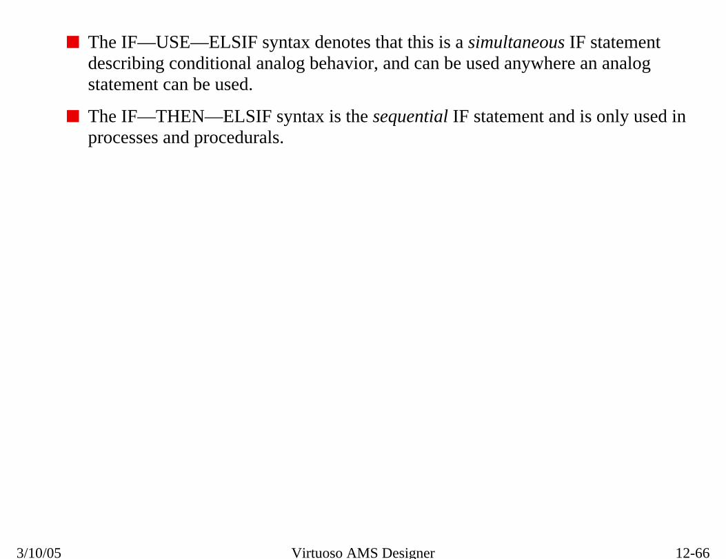
12-66
VHDL-AMS Simultaneous IF/ELSE Statements
s IF statementere an analog
nd is only used in
3/10/05 Virtuoso AMS Designer
■ The IF—USE—ELSIF syntax denotes that this is a simultaneoudescribing conditional analog behavior, and can be used anywhstatement can be used.
■ The IF—THEN—ELSIF syntax is the sequential IF statement aprocesses and procedurals.

12-67
s and signals.
with respect to
h respect tod slopes.
e is
er time from
al delay, T >=
ression)>0.0.
Introduction to the VHDL-AMS Language
Attributes of VHDL-AMS Quantities■ Use attributes to find out information about types, nature
■ Already numerous pre-defined attributes for quantities.
■ Implicit quantities result after applying the attribute.
Q'dot The derivative of quantity Q time
Q'slew(max_rising_slope,max_falling_slope)
Follows Q, but derivative wittime is limited by the specifieDefault for max_falling_slopmax_rising_slope.
Q'integ The integral of quantity Q ovzero to current time
Q'delayed(T) Quantity Q delayed by T (ide0.0 sec)
Q'above(Expression) Evaluates to TRUE if (Q-Exp

12-68
Attributes of VHDL-AMS Quantities
3/10/05 Virtuoso AMS Designer

12-69
itivity list and the a tri-state digital
readily be used in
) IS
Introduction to the VHDL-AMS Language
VHDL-AMS 'ABOVE Attribute Example—1This analog to digital converter example uses a process sens'ABOVE attribute to detect input level crossings and producesoutput voltage.
Since the 'ABOVE attribute produces a boolean output, it canan IF-THEN-ELSE statement.
ARCHITECTURE behavioral OF converter IS
CONSTANT v_il : REAL := 1.5;
CONSTANT v_ih : REAL := 3.5;
QUANTITY vin ACROSS sensp TO sensn;
BEGIN
a_to_logic : PROCESS (vin’ABOVE(v_il),vin’ABOVE(v_ih)
BEGIN
IF NOT vin’ABOVE(v_il) THEN
data <= ‘0’;
ELSIF vin’ABOVE(v_ih) THEN
data <= ‘1’;
ELSE
data <= ‘X’;
END IF;
END PROCESS a_to_logic;
END ARCHITECTURE converter;

12-70
VHDL-AMS 'ABOVE Attribute Example—1
s the threshold.
ical”
l;
3/10/05 Virtuoso AMS Designer
'ABOVE triggers an event no matter which direction the signal crosse
An ENTITY for the converter above might look like the following:
library ieee, work;
use ieee.std_logic_1164.all;
use WORK.std_decls.all; --defines “electr
ENTITY converter IS
PORT (TERMINAL sensp, sensn : electrica
data : OUT std_logic );
END converter;

12-71
ple, it does not usets for each
Introduction to the VHDL-AMS Language
VHDL-AMS 'ABOVE Attribute Example—2While this comparator example is similar to the previous exama process sensitivity list, but instead uses WAIT ON statementhreshold crossing of the single-ended input.
ARCHITECTURE my_comparator OF comparator IS
CONSTANT thrp : REAL := 50.0e-3;
CONSTANT thrm : REAL := -50.0e-3;
QUANTITY vin ACROSS sensp;
BEGIN
PROCESS IS
BEGIN
WAIT ON vin’ABOVE(thrp);
IF (vin’ABOVE(thrp)) THEN
compout <= ‘1’;
END IF;
WAIT ON vin’ABOVE(thrm);
IF (NOT vin’ABOVE(thrm)) THEN
compout <= ‘0’;
END IF;
END PROCESS;
END ARCHITECTURE my_comparator;

12-72
VHDL-AMS 'ABOVE Attribute Example—2
ical”
3/10/05 Virtuoso AMS Designer
An ENTITY for the converter above might look like the following:
library ieee, work;
use ieee.std_logic_1164.all;
use WORK.std_decls.all; --defines “electr
ENTITY comparator IS
PORT (TERMINAL sensp : electrical;
compout : OUT std_logic );
END converter;
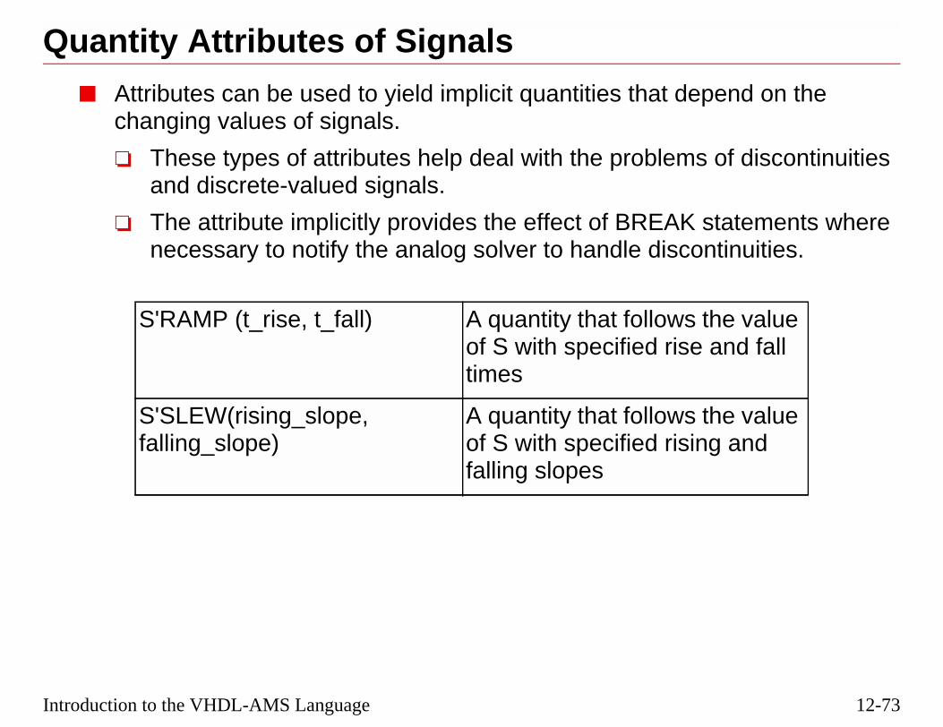
12-73
pend on the
of discontinuities
statements wherentinuities.
the value and fall
the valueg and
Introduction to the VHDL-AMS Language
Quantity Attributes of Signals■ Attributes can be used to yield implicit quantities that de
changing values of signals.
❏ These types of attributes help deal with the problemsand discrete-valued signals.
❏ The attribute implicitly provides the effect of BREAK necessary to notify the analog solver to handle disco
S'RAMP (t_rise, t_fall) A quantity that followsof S with specified risetimes
S'SLEW(rising_slope,falling_slope)
A quantity that followsof S with specified risinfalling slopes

12-74
Quantity Attributes of Signals
3/10/05 Virtuoso AMS Designer

12-75
ch, and the next
Introduction to the VHDL-AMS Language
VHDL-AMS 'RAMP Attribute ExampleThe RAMP attribute is demonstrated in this example of a switexample of an inverter:
ARCHITECTURE my_switch OF switch IS
QUANTITY vout ACROSS iout THROUGH p TO m;
SIGNAL reff : REAL := roff;
BEGIN
p1:PROCESS
BEGIN
IF din = ‘0’ THEN
reff <= ron;
ELSE
reff <= roff;
END IF;
WAIT ON din;
END PROCESS p1;
vout == iout * reff’RAMP(tr, tf);
END ARCHITECTURE my_switch;

12-76
VHDL-AMS 'RAMP Attribute Example
ical”
3/10/05 Virtuoso AMS Designer
An ENTITY for the switch above might look like the following:
library ieee, work;
use ieee.std_logic_1164.all;
use WORK.std_decls.all; --defines “electr
ENTITY switch IS
GENERIC (roff : REAL :=1.0e9;
ron : REAL :=1.0;
tr : REAL := 1.0e-6;
tf : REAL := 1.0e-6);
PORT (TERMINAL p,m : electrical;
din : IN std_logic );
END switch;

12-77
t:
nsition
Introduction to the VHDL-AMS Language
VHDL-AMS Inverter Architecture ExampleThis inverter example has a digital input and an analog outpu
ARCHITECTURE beh OF inverter IS
QUANTITY vout ACROSS iout THROUGH out1 TO gnd;
SIGNAL v_temp : REAL := 0.0;
BEGIN
PROCESS (in1)-- sensitive to digital input
BEGIN
IF in1 = '1' THEN
v_temp <= 0.0 AFTER 1 ns;
ELSE
v_temp <= 5.0 AFTER 1 ns;
END IF;
END PROCESS;
vout == v_temp'RAMP(0.1e-9, 0.1e-9); --outputs an analog tra
END beh;

12-78
VHDL-AMS Inverter Architecture Example
and fall times of
3/10/05 Virtuoso AMS Designer
■ AFTER is a way of delaying the value assignment.
■ In this example, the output transition is hard-coded to have rise 0.1 nanoseconds.
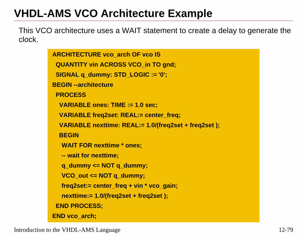
12-79
lay to generate the
Introduction to the VHDL-AMS Language
VHDL-AMS VCO Architecture ExampleThis VCO architecture uses a WAIT statement to create a declock.
ARCHITECTURE vco_arch OF vco IS
QUANTITY vin ACROSS VCO_in TO gnd;
SIGNAL q_dummy: STD_LOGIC := '0';
BEGIN --architecture
PROCESS
VARIABLE ones: TIME := 1.0 sec;
VARIABLE freq2set: REAL:= center_freq;
VARIABLE nexttime: REAL:= 1.0/(freq2set + freq2set );
BEGIN
WAIT FOR nexttime * ones;
-- wait for nexttime;
q_dummy <= NOT q_dummy;
VCO_out <= NOT q_dummy;
freq2set:= center_freq + vin * vco_gain;
nexttime:= 1.0/(freq2set + freq2set );
END PROCESS;
END vco_arch;

12-80
VHDL-AMS VCO Architecture Example
ical”
3/10/05 Virtuoso AMS Designer
An ENTITY for the vco above might look like the following:
library ieee, work;
use ieee.std_logic_1164.all;
use ieee.math_real.all;
use WORK.std_decls.all; --defines “electr
ENTITY vco IS
GENERIC (center_freq : REAL :=1.0e8;
vco_gain : REAL :=1.0e6);
PORT (TERMINAL VCO_in : electrical;
VCO_out : OUT std_logic := ’0’);
END vco;

12-81
, which returns the
ut keeps on going).
hen called from alue when called
Introduction to the VHDL-AMS Language
The NOW Function for Time Retrieval■ VHDL-AMS provides a predefined function called NOW
current simulation time when called, as in:
vout == 0.0 + 0.5e4*NOW
This expression will produce a ramp from 0 to 5 in 1ms (b
■ NOW is equivalent to $abstime in Verilog-AMS.
❏ In VHDL-AMS, you might see:
v == ampl*sin(2.0*math_pi*freq*NOW);
❏ In Verilog-AMS, you might see:
v <+ ampl*sin(2.0*PI*freq*$abstime);
■ NOW is overloaded to return time as a discrete value wdigital context and also to return time as a continuous vafrom an analog context.

12-82
The NOW Function for Time Retrieval
3/10/05 Virtuoso AMS Designer

12-83
Introduction to the VHDL-AMS LanguageLabs
Lab 12-1 VHDL-AMS PWM Testbench
Lab 12-2 VHDL-AMS Switched Mode Power Supply
Lab 12-3 Writing a VHDL-AMS Inverter Module
Lab 12-4 Writing a VHDL-AMS VCO (Optional)

12-84
Labs
3/10/05 Virtuoso AMS Designer

®
March 10, 2005
Module 13
13 Migrating D AMS
esigns to
13-2
3/10/05 Virtuoso AMS Designer
13-3
ed-signal design to
Migrating Designs to AMS
Topics in this Module■ Steps to migrating a Cadence® Design Framework II mix
AMS
■ Library conversions
■ Designing for AMS compliance

13-4
Migrating Designs to AMS
and Appendixes B
3/10/05 Virtuoso AMS Designer
■ Refer to the Virtuoso AMS Environment User Guide, Chapter 7and C for more information on migrating designs.

13-5
to AMS
esigner using the
to schematics and
S Netlister, or
Migrating Designs to AMS
Steps to Migrating a Mixed-Signal Design1. Prepare a cds.lib, hdl.var, and worklib.
2. Convert the analog primitives for use in Virtuoso® AMS DConversion Tool Box (if needed).
3. Compile the digital libraries.
4. Make any modifications necessary for AMS compatibilityVerilog-A modules.
5. Netlist the schematic library using Check and Save, AMDesign Prep.
6. Create a config view.
7. Add values for non-default design variables.

13-6
Steps to Migrating a Mixed-Signal Design to AMS
3/10/05 Virtuoso AMS Designer

13-7
they haven’t been
AMS simInfo
pectre.
Info) stored in theformation” box.
o from the cell’s
Migrating Designs to AMS
Converting Analog Libraries to AMSConvert analog primitives for use in Virtuoso AMS Designer, ifalready.
1. From the CIW, execute Tools—Conversion Tool Box—from Spectre.
2. Select the library name to be converted.
3. Select “Process only cells with the following views” — s
4. If there could be previous AMS simulation information (simcells’ CDF files, check the “Overwrite AMS simulation in
5. Check both boxes under “Mark a cell as a primitive”:
❏ “If any of modelname/model/modelName are found”
❏ “If the cell has a “spectre” view”
6. Click OK, and the conversion tool will create ams simInfSpectre® simInfo.
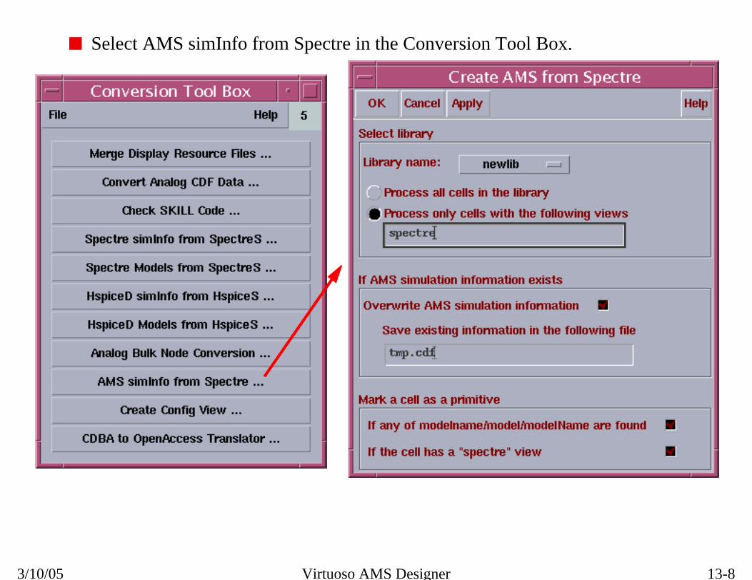
13-8
Converting Analog Libraries to AMS
3/10/05 Virtuoso AMS Designer
■ Select AMS simInfo from Spectre in the Conversion Tool Box.

13-9
ponent’s CDF.
eters fields.
Migrating Designs to AMS
Modifying SimInfo for AMSThe ams simInfo needs to be modified or verified in each com
To do so, execute Tools—CDF—Edit from the CIW window.
1. Enter the library name and the first cell to be modified.
2. Set the CDF type to Base.
3. Scroll down to Simulation Information, and click Edit.
4. Select “ams” from the cyclic field for Choose Simulator.
5. Add “model” to both the otherParameters and instParam
6. Add the terminal names to the termOrder field.
7. At the bottom of the form, add “t” to the isPrimitive field.
8. Click OK on the Edit Simulation Information form.
9. Click OK on the Edit Component CDF form.
10. Repeat with each cell name to be modified.

13-10
Modifying SimInfo for AMS
3/10/05 Virtuoso AMS Designer
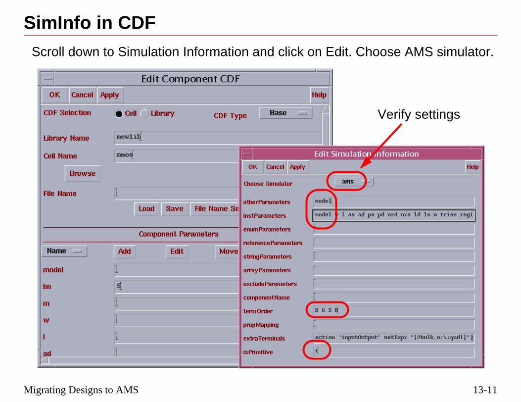
13-11
se AMS simulator.
erify settings
Migrating Designs to AMS
SimInfo in CDFScroll down to Simulation Information and click on Edit. Choo
V

13-12
SimInfo in CDF
3/10/05 Virtuoso AMS Designer

13-13
g=spectre for aodel file starts withtre.
e full path to the
ath and section.
Migrating Designs to AMS
Including Analog Model Files in AMS■ Verify that the analog model files start with simulator lan
Spectre format model file. Verify that a SPICE format msimulator lang=spice and ends with simulator lang=spec
■ Add a MODELPATH statement to the hdl.var file with thmodel file(s).
or
■ Use the Model Form in the Hierarchy Editor to set the p

13-14
Including Analog Model Files in AMS
3/10/05 Virtuoso AMS Designer

13-15
formation so thatwith this example
e
e with the Virtuoso
Migrating Designs to AMS
Compile Digital Libraries■ Digital primitives must have a wrapper to provide port in
Connect Modules can be added correctly, as illustrated from the sample library.
module nand2 (Y,A,B);
output Y;
input A;
input B;
nand i0 (Y,A,B); // nand is a digital primitiv
endmodule
■ Digital libraries must be compiled to the 5.X format to usAMS Environment.
ncvlog -ams -use5x digital_lib_module.v

13-16
Compile Digital Libraries
manager mayhe utility
t Modules librarytLibCompile
cds.lib file.
3/10/05 Virtuoso AMS Designer
■ After installing the Virtuoso AMS Designer software, the systempre-compile the included libraries, such as sample, by running tamsLibCompile from the IC5.X.XX install directory.
■ The system manager may also pre-compile the included Connecby running the utility /tools/affirma_ams/etc/install/amsConnecfrom the IUSXX install directory.
■ These pre-compiled libraries can then be included in the project

13-17
pliance—1
underscore
lash “\” at the
inals to facilitateleast cover all the
er should have the
ames.
Migrating Designs to AMS
Designing for Virtuoso AMS Designer Com■ Identifiers:
❏ Begin with a lower-case letter, not a number.
❏ Continue with lower-case letters or numbers, and thesymbol, but do not end with an underscore.
❏ Avoid using reserved words, or escape them with a sbeginning and a space at the end.
■ Terminals:
❏ Every view of a cell should use the same set of termswitching from one to another in configurations, or atterminals defined in the symbol view.
❏ For VHDL, nets and terminals connected to each othsame identifier.
❏ Don’t use variable names that are the same as pin n

13-18
Designing for AMS Designer Compliance—1
dix E for a list of
3/10/05 Virtuoso AMS Designer
■ Refer to the Cadence Verilog-AMS Language Reference, Appenkeywords that should not be used as identifiers.

13-19
pliance—2
, ranges with2>(A,B), and suffix
SB, but not both.
bing.
xcept for
ng. Set default
nd iPar.
are defined withce.
s are defined with
Migrating Designs to AMS
Designing for Virtuoso AMS Designer Com■ Buses:
❏ Avoid the use of concatenated, non-consecutive bitsincrements other than one, prefix repeat operators, <*repeat operators, a<0:2*2>.
❏ Use a consistent range direction, MSB:LSB or LSB:M
❏ Sparse buses may affect the ability to use cross-pro
❏ Mixed-signal buses are supported in Verilog-AMS, econcatenated buses.
■ CDFs:
❏ Library component CDFs are not used during netlistivalues in Cell CDFs.
■ Parameters:
❏ Do not use atPar or dotPar expressions. Use pPar a
❏ Ensure that the parameters used in iPar expressionsdefault values in the CDF for the master of the instan
❏ Ensure that the parameters used in pPar expressiondefault values in the CDF for the instantiated cell.

13-20
Designing for AMS Designer Compliance—2
current instance.
he parent instance
apter 3, for more
3/10/05 Virtuoso AMS Designer
■ Notes on parameters:
❑ iPar(“x”) lets you reference the value of parameter x on the
❑ pPar(“x”) lets you reference the value of parameter x from tof the component.
❑ Refer to the Component Description Format User Guide, Chinformation on passing parameter values.

13-21
mplex PLL
Migrating Designs to AMS
Labs
Lab 13-1 Migrating a Peak Detector Design
Lab 13-2 Mixed-Signal, Mixed-Language Simulation of a Co

13-22
rse, and should be
3/10/05 Virtuoso AMS Designer
Congratulations! You have completed the Virtuoso AMS Designer couready to successfully simulate mixed-language, mixed-signal designs.

®
March 10, 2005
Module 14
14 Virtuoso A nment Reference (Optional)
MS Enviro
14-2
3/10/05 Virtuoso AMS Designer
14-3
Virtuoso AMS Environment Reference (Optional)Topics in this Module■ AMS Netlister
■ AMS Options
❏ CIW Tools—AMS—Options
❏ Hierarchy Editor AMS—Options
■ The remaining AMS Menu items
❏ Run Directory
❏ Global Signals
❏ Design Variables
❏ Analog Models Setup
❏ Plot/Save
❏ Run Simulation
❏ Waveform Viewer
❏ Log File Viewer
■ AMS in ADE Options
14-4
Virtuoso AMS Environment (Optional)
ns and settings,g the ones not
ws available from
from the Cadence®
3/10/05 Virtuoso AMS Designer
■ This module will review the Virtuoso® AMS Environment optiosome of which have been explained in prior modules, but addinpreviously discussed.
■ This module can be used as a reference to all the forms and windothe Virtuoso AMS Environment.
■ A number of the options can be set in multiple locations.
■ Additional information on each form and option can be obtainedonline documentation.

14-5
:
e in a Composerns).
hy Editor.
ine.
etlist.
Virtuoso AMS Environment Reference (Optional)
AMS Netlister ToolThere are several ways to create an AMS netlist of a cellview
■ Automatically netlist a schematic using Check and Savwindow (as long as it’s enabled in Tools—AMS—Optio
■ Use Design Prep from the AMS menu within the Hierarc
■ Use the amsdirect command from the UNIX command l
■ Use the Library Netlister from the CIW Tools—AMS—N

14-6
AMS Netlister Tool
wName -verilog
erated even if the Check and Save
.)
generate ary of schematicEligible views forAMS—View
ibrary are netlisted.
ell are netlisted.
MS netlists, on allry.
etlist and check
update thevided the
3/10/05 Virtuoso AMS Designer
■ amsdirect from the UNIX command line has the format:amsdirect -lib libName -cell cellName -view vie
❑ The -verilog argument forces a verilog.vams netlist to be genPerform AMS checks and Generate AMS netlist boxes in theOptions aren’t set. (If they are set, then -verilog isn’t needed
■ The AMS Netlister form (Tools—AMS—Netlist) allows you toVerilog-AMS netlist and compile the netlist from an entire libraviews, or all views of a single cell, or just a specific cell view. (netlisting are specified in AMS Options—Netlister—Verilog-Selection form).
❑ If a cell is not specified, all eligible views of every cell in the l
❑ If a view is not specified, all eligible views of the specified c
❑ Compiling can also be enabled or disabled on the generated AVerilog® files in the library, or on all VHDL files in the libra
■ For recompiling older NC libraries, uncheck Generate AMS NCompile all Verilog files.
■ AMS netlisting will also occur when you use the CDF editor to component description format (CDF) information for a cell, pronetlistAfterCdfChange variable in the ams.env file is set to t.

14-7
S—Options menu
ve action from aAMS—Options.
from
Virtuoso AMS Environment Reference (Optional)
AMS Options■ Many AMS options can be set from the CIW Tools—AM
prior to opening the Hierarchy Editor.
❏ The type of netlist generated during a Check and Saschematic window can only be set from CIW Tools—
Setting AMS optionsthe CIW Tools menu

14-8
AMS Options
W are stored in thes in the Hierarchy
3/10/05 Virtuoso AMS Designer
■ Netlisting options and compilation variables selected from the CIams.env file in the CWD. Options selected from AMS—OptionEditor are stored in the run directory ams.env file.

14-9
Options menu.
ivitiesschematic
first box.
when Check and
and Save, check not checked, the
Virtuoso AMS Environment Reference (Optional)
AMS Options—Check and Save■ This form is only available from the CIW Tools—AMS—
■ The three check boxes determine what AMS-related acthappen when Check and Save is pressed in a Composerwindow.
❏ To perform AMS checking on a schematic, check the
❏ To generate a Verilog-AMS netlist from a schematic Save is used, check the second box.
❏ To Compile the generated AMS netlist after a Checkthe third box. But, if the Generate AMS netlist box iscompile will not occur.

14-10
AMS Options—Check and Save
a Check and Savelts: Verilog-AMS
ssing Check and for AMS
ierarchical.
ptions form menu
d Categories fieldAMS Designer to display the
3/10/05 Virtuoso AMS Designer
■ The netlisting options on this form must be selected prior to doingin a schematic, because they determine which type of netlist resuor Spectre®.
■ Typical usage in AMS would be to check all three boxes, so preSave on a schematic generates a Verilog-AMS netlist, checks itcompliance, and compiles it.
■ Check and Save only netlists the displayed schematic. It is not h
■ Environment files can also be loaded or saved from the AMS Obar.
■ The particular AMS Options forms are selected from the left-hanin the AMS—Options form. In earlier versions of the Virtuoso Environment, the CIW Options were chosen using a cyclic fieldvarious options forms.

14-11
E)nd a Run DirectoryAMS—Options
Virtuoso AMS Environment Reference (Optional)
AMS Options from the Hierarchy Editor (H■ Once the AMS plug-in for the Hierarchy Editor is started a
chosen, additional options become available through themenu.
❏ Netlister
❏ Compiler
❏ Elaborator
❏ Simulator
❏ Global Design Data
❏ Waveforms

14-12
AMS Options from the Hierarchy Editor (HE)
play the associated
3/10/05 Virtuoso AMS Designer
■ Selecting a major category causes the Option Category tree to disforms.

14-13
ounter before it
Virtuoso AMS Environment Reference (Optional)
AMS Options—Netlister (Scaling)■ The Netlister Options form allows you to set:
❏ The maximum number of errors the netlister can encstops processing the design.
❏ The scaling notation for parameter values.
CIW Tools
HE AMS Menu

14-14
AMS Options—Netlister (Scaling)
generated.
e numerical formatr decimal notation
3/10/05 Virtuoso AMS Designer
■ If errors are encountered during netlisting, the netlist will not be
■ If “Use scaling notation for parameter values” is checked, then thfor parameter values can be set to use either scientific notation oinstead of the default scale factors, such as 5u or 10p.

14-15
sions) of language
Virtuoso AMS Environment Reference (Optional)
AMS Options—Netlister (Language Exten■ The Netlister—Verilog-AMS form permits the inclusion
extensions.
CIW Tools
HE AMS Menu

14-16
AMS Options—Netlister (Language Extensions)
extended languageluded.
3/10/05 Virtuoso AMS Designer
■ Check “Conditionally include language extensions” if you wantconstructs such as an `ifdef INCA conditional directive to be inc
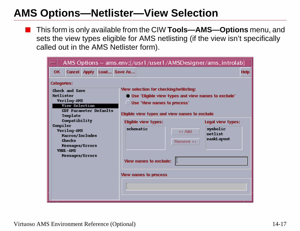
14-17
ptions menu, and isn’t specifically
Virtuoso AMS Environment Reference (Optional)
AMS Options—Netlister—View Selection■ This form is only available from the CIW Tools—AMS—O
sets the view types eligible for AMS netlisting (if the viewcalled out in the AMS Netlister form).

14-18
AMS Options—Netlister—View Selection
also be madew.”
Hierarchy Editor.
3/10/05 Virtuoso AMS Designer
■ “schematic” is the default selection, but user-defined views caneligible for netlisting, such as “myschematic” or “schematic_ne
■ This form is not available in the AMS Options menu within the

14-19
Defaultse.
Virtuoso AMS Environment Reference (Optional)
AMS Options—Netlister—CDF Parameter ■ Any parameters that need default values can be set her
CIW Tools
HE AMS Menu

14-20
AMS Options—Netlister—CDF Parameter Defaults
r does not have a
.
3/10/05 Virtuoso AMS Designer
■ To add a parameter:
❑ Enter its name in the Name field.
❑ Select integer or real in the Type field.
❑ Enter a default value in the Value field.
■ The AMS Netlister will use this value as default if the parametevalue set in the schematic (CDBA database).
■ The Global Default Parameter Value should normally be set to 0

14-21
Virtuoso AMS Environment Reference (Optional)AMS Options—Netlister—Template■ With the options in this category, you can specify:
❏ Headers for AMS netlists.
❏ Names of files to be included via `include directives.
CIW Tools
HE AMS Menu

14-22
AMS Options—Netlister—Template
41.XXX
d in AMS and caning it as a default
ntains variousdules that computexample.
e directive, but the
option, which cannts form, or from
3/10/05 Virtuoso AMS Designer
■ The added default header for netlists will appear similar to:// Verilog-AMS netlist generated by the AMS netlister, version 5.1.// Cadence Design Systems
■ The netlister will not verify the existence of included files.
■ disciplines.vams (or an equivalent file) defines the disciplines usebe automatically included in new Verilog-AMS modules by settinclude for AMS netlists.
❑ constants.vams is another commonly used include file that conumerical constants, and should be included in behavioral movalues using those constants, such as PI or temperature, for e
■ The include name will be prepended to the netlist with an `includnetlister will not check to see if the include file exists.
❑ The specific file can be further directed with a ncvlog -incdirbe set as a default in the AMS Options—Compiler Argumethe AMS Options menu within the Hierarchy Editor.

14-23
ept (yes), or warnhematics and AMS
Virtuoso AMS Environment Reference (Optional)
AMS Options—Netlist—Compatibility■ The user can set AMS netlisting to either reject (no), acc
on the following incompatibility issues between drawn scnetlists.
CIW Tools
HE AMS Menu
14-24
AMS Options—Netlist—Compatibility
g netlisting, no
uring netlisting,e corrected in the
MS language.
ames that are legal
ssible to create ale than one created
n it encounters ance, but it does not
window, underects reporting, not
3/10/05 Virtuoso AMS Designer
■ The selections shown in the figure are typical.
■ If an item is set to No - Print Errors, and there is an issue durinnetlist will be formed.
■ If an item is set to Yes - Print Warnings, and there is an issue dnetlisting continues but a warning is displayed, and the issues arfollowing fashion:
❑ Illegal identifiers are escaped to names that are legal in the A
❑ Names that cause collisions are mapped to system-generated nin the AMS language.
❑ With conflicting bus ranges, netlisting will continue if it is povalid netlist, but the generated netlist is likely to be less readabfrom AMS-compliant bus ranges.
❑ Sparse buses are over-declared (filled out).
■ If an item is set to Yes - Silently, netlisting continues even wheexception by making changes to bring the design into complianissue warnings.
■ AMS Compatibility can also be set in the Composer Schematic Options—Check Rules Setup—AMS, but this location only affnetlisting.

14-25
n must be set here.
-only libraries that
ption by checking
CIW Tools
Virtuoso AMS Environment Reference (Optional)
AMS Options—Compiler■ The location of the hdl.var file used for the simulation ru
■ Libraries can be excluded from compilation, such as readhave already been compiled.
■ Verilog-D modules may be compiled without the -ams othe box.
HE AMS Menu

14-26
AMS Options—Compiler
editor. In the, at least with
ns can be disabled,r if the Verilog-D
cked, all files withfiles with the
3/10/05 Virtuoso AMS Designer
■ Clicking on Edit with an hdl.var file selected brings up the text Virtuoso AMS Environment, the modelpath must be fully statedreference to the run directory.
■ For digital-only Verilog modules, compiling with AMS extensiowhich is particularly useful when shelling Verilog into VHDL, omodules use identifiers that are keywords in Verilog-AMS.
❑ If “Compile digital Verilog files without -ams option” is chethe extension .v will be compiled without using AMS, while extension .vams will be compiled using AMS.

14-27
MS compiler.
rs.
Virtuoso AMS Environment Reference (Optional)
AMS Options—Compiler—Verilog-AMS■ This form controls the options available for the Verilog-A
■ Compilation will stop after the maximum number of erro
■ The log file can be disabled, or appended to.
■ Additional arguments can be added.
CIW ToolsHE AMS Menu

14-28
AMS Options—Compiler—Verilog-AMS
ign units, source added, or if a that introduces a
breakpoints ande.
efine compileres as cell
L source files.nable lexical
L source filesslate on as if theyo that the codehe Verilog syntax
by the PLI
3/10/05 Virtuoso AMS Designer
Field ncvlog equivalent Effect
Update if needed -update Recompiles the design after desfiles, or compiler directives aredesign unit is changed in a waynew cross-file dependency.
Enable linedebug
-linedebug Enables support for setting linefor single-stepping through cod
Mark cells withdefines
-libcell Inserts `celldefine and `endcellddirectives to tag module instancinstances.
Enable pragma -pragma Parses pragmas contained in HDThis option is not available if Epragma processing is selected.
Enable lexicalpragmaprocessing
-lexpragma Parses pragmas contained in HDand treats translate off and tranare Verilog `ifdef 0 and `endif sbetween them is not written to ttree.
Disable memorypacking
-nomempack Prepares design units for accessroutine tf-nodeinfo.

14-29
/Includesrectories during
Virtuoso AMS Environment Reference (Optional)
AMS Options—Compiler—Verilog Macros■ This form allows the inclusion of macros or additional di
compilation.
CIW Tools
HE AMS Menu

14-30
AMS Options—Compiler—Verilog Macros/Includes
alue.
ame to include.
3/10/05 Virtuoso AMS Designer
■ To include a macro, click on Add and enter a macro name and v
❑ This is equivalent to ncvlog -define from the command line.
■ To include directories, click on Add and enter a new directory n
❑ This is equivalent to ncvlog -incdir from the command line.

14-31
Virtuoso AMS Environment Reference (Optional)AMS Options—Compiler—Verilog ChecksCIW tools
HE AMS Menu

14-32
AMS Options—Compiler—Verilog Checks
3/10/05 Virtuoso AMS Designer

14-33
s
Virtuoso AMS Environment Reference (Optional)
AMS Options—Verilog Compiler MessageCIW Tools
HE AMS Menu

14-34
AMS Options—Verilog Compiler Messages
iler runs.
and CPU usage
sages.
pecified codes.
een but does note log file
es related to
ompatibility with
ny or functions in
3/10/05 Virtuoso AMS Designer
Field ncvlog equivalent Effect
Print informationalmessages
-messages Prints messages as the comp
Display runtimestatus
-status Prints statistics on memory after compilation.
Suppress allwarnings
-neverwarn Suppresses all warning mes
Suppress specificwarnings
-nowarn Suppresses warnings with s
Suppress output toscreen
-nostdout Suppresses output to the scrchange what is written to th
Suppress pragmawarnings
-nopragmawarn Suppresses warning messagpragmas.
Enable IEEE 1364lint checker
-ieee1364 Checks the source code for cthe IEEE Std 1364.
Check for standardsystem tasks
-checktasks Checks for the presence of anon-predefined system tasksthe source code.

14-35
S compiler.
rs.
CIW Tools
Virtuoso AMS Environment Reference (Optional)
AMS Options—Compiler—VHDL-AMS■ This form controls the options available for the VHDL-AM
■ Compilation will stop after the maximum number of erro
■ The log file can be disabled or appended to.
■ Additional arguments can be added.
HE AMS Menu

14-36
AMS Options—Compiler—VHDL
sign units, source added, or if a that introduces a
supported in this
breakpoints ande.
hecking.
me VHDL rules.
3/10/05 Virtuoso AMS Designer
Field ncvhdl equivalent Effect
Update if needed -update Recompiles the design after defiles, or compiler directives aredesign unit is changed in a waynew cross-file dependency.
Enable VHDL93features
-v93 Enables the VHDL-93 featuresrelease (default).
Enable linedebug
-linedebug Enables support for setting linefor single-stepping through cod
Enable VITALchecks
-novitalcheck Turns on VITAL compliance c
Enable relaxedVHDLinterpretation
-relax Relaxes the interpretation of so

14-37
s
Virtuoso AMS Environment Reference (Optional)
AMS Options—Compiler—VHDL MessageCIW Tools
HE AMS Menu

14-38
AMS Options—Compiler—VHDL Messages
iler runs.
and CPU usage
ages.
ecified codes.
een but does not log file
es related to
3/10/05 Virtuoso AMS Designer
Field ncvlog equivalent Effect
Print informationalmessages
-messages Prints messages as the comp
Display runtimestatus
-status Prints statistics on memory after compilation.
Suppress allwarnings
-neverwarn Suppresses all warning mess
Suppress specificwarnings
-nowarn Suppresses warnings with sp
Suppress output toscreen
-nostdout Suppresses output to the scrchange what is written to the
Suppress pragmawarnings
-nopragmawarn Suppresses warning messagpragmas.

14-39
borator.
s.
Virtuoso AMS Environment Reference (Optional)
AMS Menu—Options—Elaborator■ This form controls the AMS options available for the ela
■ Elaboration will stop after the maximum number of error
■ The log file can be disabled or appended to.
■ Additional arguments can be added.

14-40
AMS Menu—Options—Elaborator
sign units, source added, or if a that introduces a
ete nets for whichned.
esolution
erilog modules. If a default is noterror will result.
rameters that
3/10/05 Virtuoso AMS Designer
Field ncelab equivalent Effect
Update designunits if needed
-update Recompiles the design after defiles, or compiler directives aredesign unit is changed in a waynew cross-file dependency.
Ignore sourcefile timestampswhen using-update
-nosource
Defaultdiscipline
-discipline Specifies the discipline of discra discipline is otherwise undefi
Use detaileddisciplineresolution
-dresolution Uses the Detailed Discipline Ralgorithm.
Defaulttimescale
-timescale Sets the default timescale for Vthat do not have a timescale setset here or in some module, an
Allow undefinedparameters
-noparamerr Tells the elaborator to allow paaren’t used for simulation.
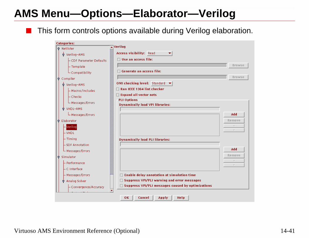
14-41
gration.
Virtuoso AMS Environment Reference (Optional)
AMS Menu—Options—Elaborator—Verilo■ This form controls options available during Verilog elabo

14-42
AMS Menu—Options—Elaborator—Verilog
for all objects in
for PLI and Tcl.
ing level to use.
ecified VPI or
PI routines thation time.
warning and errorints a warninge that a PLI read,ess violation is
3/10/05 Virtuoso AMS Designer
Field ncelab equivalent Effect
Access visibility -access Sets the visibility accessthe design.
Use an access file -afile Specifies an access file.
Generate an accessfile
-genafile Generates an access file
OMI checkinglevel
-omicheckinglevel Specifies the OMI check
Expand all vectornets
-expand Expands all vector nets.
Dynamically loadVPI/PLI libraries
-loadvpi-loadpli1
Dynamically loads the spPLI 1.0 application.
Enable delayannotation atsimulation time
-anno_simtime Enables the use of PLI/Vmodify delays at simulat
Suppress VPI/PLImessages, or justthose caused byoptimizations
-plinowarn-plinooptwarn
Disables printing of PLImessages. If opt only, prmessage only the first timwrite, or connectivity accdetected.

14-43
ation.
Virtuoso AMS Environment Reference (Optional)
AMS Menu—Options—Elaborator—VHDL■ This form controls options available during VHDL elabor
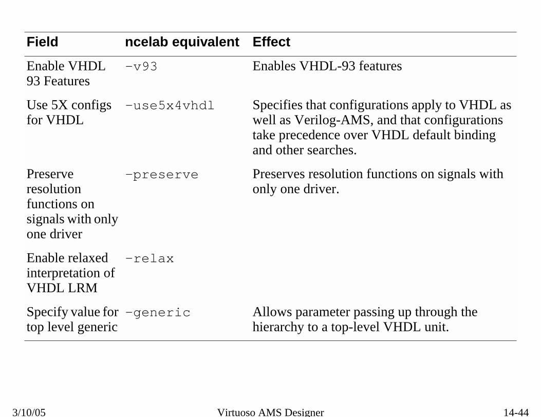
14-44
AMS Menu—Options—Elaborator—VHDL
pply to VHDL ast configurations
default binding
on signals with
through theL unit.
3/10/05 Virtuoso AMS Designer
Field ncelab equivalent Effect
Enable VHDL93 Features
-v93 Enables VHDL-93 features
Use 5X configsfor VHDL
-use5x4vhdl Specifies that configurations awell as Verilog-AMS, and thatake precedence over VHDL and other searches.
Preserveresolutionfunctions onsignals with onlyone driver
-preserve Preserves resolution functionsonly one driver.
Enable relaxedinterpretation ofVHDL LRM
-relax
Specify value fortop level generic
-generic Allows parameter passing up hierarchy to a top-level VHD

14-45
g and VHDL
Virtuoso AMS Environment Reference (Optional)
AMS Menu—Options—Elaborator—Timing■ This form allows setting various timing options for Verilo
elaboration.

14-46
AMS Menu—Options—Elaborator—Timing
e Virtuoso AMS
r Guide.
3/10/05 Virtuoso AMS Designer
■ For information on these fields, see:
❑ Chapter 11, “Elaborating and Simulating Your Design” in thEnvironment User Guide
❑ Chapter 7, “Elaborating” in the Virtuoso AMS Simulator Use
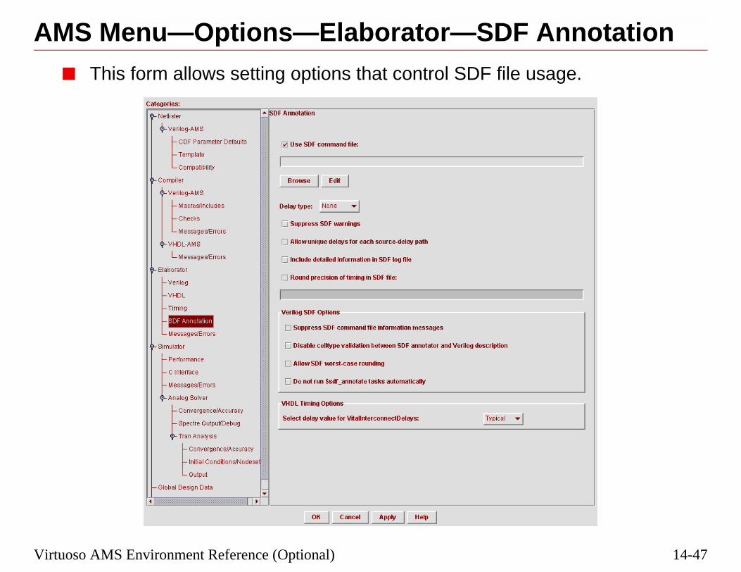
14-47
nnotationge.
Virtuoso AMS Environment Reference (Optional)
AMS Menu—Options—Elaborator—SDF A■ This form allows setting options that control SDF file usa

14-48
AMS Menu—Options—Elaborator—SDF Annotation
e Virtuoso AMS
r Guide.
3/10/05 Virtuoso AMS Designer
■ For information on these fields, see:
❑ Chapter 11, “Elaborating and Simulating Your Design” in thEnvironment User Guide
❑ Chapter 7, “Elaborating” in the Virtuoso AMS Simulator Use

14-49
ges/Errorsof error messages
Virtuoso AMS Environment Reference (Optional)
AMS Menu—Options—Elaborator—Messa■ This form allows setting options that control the display
during elaboration.

14-50
AMS Menu—Options—Elaborator—Messages/Errors
during
and CPU usage
ing messages.
ified warning
ified warning
opyright banner.
dule and UDP
tation.
3/10/05 Virtuoso AMS Designer
Field ncelabequivalent
Effect
Print informationmessages
-messages Prints informative messageselaboration.
Display runtime status -status Prints statistics on memory after elaboration.
Suppress all warnings -neverwarn Disables printing of all warn
Suppress specificwarnings
-nowarn Disables printing of the specmessage.
Suppress output toscreen
-nostdout Disables printing of the specmessage.
Suppress copyrightinformation
-nocopyright Suppresses printing of the c
Print messages aboutresolving instances(Verilog only)
-libverbose Displays messages about moinstantiations.
Enable code coveragefor entire (digital only)
-coverage Enables coverage instrumen

14-51
lation.
Virtuoso AMS Environment Reference (Optional)
AMS Menu—Options—Simulator■ The top-level Simulator Options form allows:
❏ Setting the maximum number of errors.
❏ Setting a SimVision Tcl script file to control the simu
❏ Setting update options and additional arguments.

14-52
AMS Menu—Options—Simulator
SimVision Tcl
be recompiled or
s field.
3/10/05 Virtuoso AMS Designer
■ The log file can be disabled or appended to.
■ Use the full path (or the path relative to the run directory) to thescript file.
■ If the “Update if needed” box is checked, any changed files willre-elaborated as needed before simulation begins.
■ Additional arguments may be added to the Additional argument

14-53
anceorm, and a profiler
ost of the solvers
Virtuoso AMS Environment Reference (Optional)
AMS Menu—Options—Simulator—Perform■ The simulator performance can be controlled from this f
invoked that will report on which design units consume mspend time.

14-54
AMS Menu—Options—Simulator—Performance
ediate objects
so that data
level to use.
of the design.
to be profiled.
3/10/05 Virtuoso AMS Designer
Field ncsim equivalent Effect
Use reducedmemory size
-redmem Turns off loading of intermgenerated by the compiler.
Do not bufferoutput
-unbuffered Bypasses the file I/O bufferdisplays immediately.
OMI checkinglevel
-omicheckinglevel Specifies the OMI checking
Generateruntime profile(digital only)
-profile Generates a run time profile
Allow profilingof threadedprocesses
-profthread Allows threaded processes

14-55
faceled in this form.
Virtuoso AMS Environment Reference (Optional)
AMS Menu—Options—Simulator—C Inter■ The loading of external VCI and VPI files can be control

14-56
AMS Menu—Options—Simulator—C Interface
pplication.
arning and error
nly the first timennectivity access
g in VDArformance.
3/10/05 Virtuoso AMS Designer
Field ncsim equivalent Effect
Verilog Only
Dynamically loadVPI libraries
-loadvpi Dynamically loads a VPI a
SuppressVPI/PLI warningand errormessages
-plinowarn Disables printing of PLI wmessages.
SuppressVPI/PLImessages causedby optimization
-plinooptwarn Prints a warning message othat a PLI read, write, or coviolation is detected.
VHDL Only
Disableconstraintchecking in VDAapplications
-nocifcheck Disables constraint checkinfunctions, for increased pe

14-57
es
Virtuoso AMS Environment Reference (Optional)
AMS Menu—Options—Simulator—Messag■ Simulator messages can be controlled in this form.

14-58
AMS Menu—Options—Simulator—Messages
uring simulation.
d CPU usage after
ng messages.
fied warning
st output to the
e information.
ages.
3/10/05 Virtuoso AMS Designer
Field ncsim equivalent Effect
Printinformationalmessages
-messages Prints informative messages d
Display runtimestatus
-status Prints statistics on memory ansimulation.
Suppress allwarnings
-neverwarn Disables printing of all warni
Suppress specificwarnings
-nowarn Disables printing of the specimessage.
Suppress outputto screen
-nostdout Suppresses the printing of moscreen.
Print extendedVHDL assertmessages
-extassertmsg Prints extended assert messag
Suppress e-pulseerror messages
-epulse_no_msg Suppresses e-pulse error mess

14-59
Solverlation Control File
els during
Virtuoso AMS Environment Reference (Optional)
AMS Menu—Options—Simulator—Analog■ The Analog Solver form allows the selection of the Simu
by checking the Use Simulation Control File box.
■ The use of table models derived from the BSIM3v3 modsimulation can be set up in this form.

14-60
AMS Menu—Options—Simulator—Analog Solver
ectre models fors a table modelSpectre model for
for drain/sourceefault.
3/10/05 Virtuoso AMS Designer
Field ncsim equivalent Effect
Model evaluation mos_model “Standard” uses SPICE or Spsimulation. “Accelerated” usegenerated from the SPICE or faster simulation.
Grid size mos_vres 0.05 is the default
Noise reductionthreshold
maxrsd Upper limit of approximationparasitic resistors. 0.0 is the d
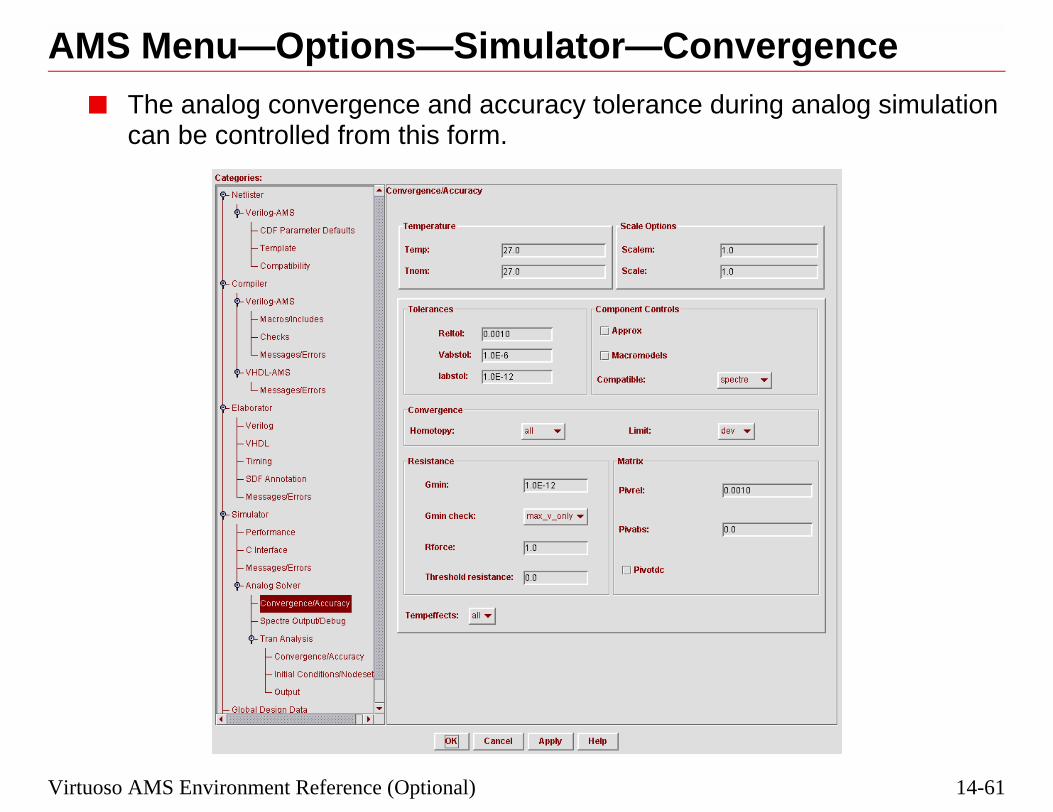
14-61
genceanalog simulation
Virtuoso AMS Environment Reference (Optional)
AMS Menu—Options—Simulator—Conver■ The analog convergence and accuracy tolerance during
can be controlled from this form.

14-62
AMS Menu—Options—Simulator—Convergence
re explained in theso Analog Design
3/10/05 Virtuoso AMS Designer
■ The options selectable on the subform, Convergence/Accuracy, aVirtuoso AMS Simulator User Guide, Chapter 8, and the VirtuoEnvironment User Guide, Chapter 7.

14-63
/Debugion are controlled
Virtuoso AMS Environment Reference (Optional)
AMS Menu—Options—Simulator—Output■ The output file and debug options during analog simulat
from this form.

14-64
AMS Menu—Options—Simulator—Output/Debug
ned in the Virtuoso Design
3/10/05 Virtuoso AMS Designer
■ The options selectable on the subform, Output/Debug, are explaiAMS Simulator User Guide, Chapter 8, and the Virtuoso AnalogEnvironment User Guide, Chapter 7.

14-65
er to set theing a Simulation
Virtuoso AMS Environment Reference (Optional)
AMS Menu—Options—Simulator—AnalogSolver—Tran Analysis
■ The Tran Analysis form, and its subforms, allows the usSpectre® transient simulation control cards in place of usControl File.

14-66
AMS Menu—Options—Simulator—Analog Solver—Tran Analysis
y, InitialS Simulator User, Chapter 7.
3/10/05 Virtuoso AMS Designer
■ The options selectable on the sub-forms, Convergence/AccuracConditions, and Output/Debug are explained in the Virtuoso AMGuide, Chapter 8, and the Spectre Circuit Simulator User Guide

14-67
als cell when itignals, such as
a library name and
Virtuoso AMS Environment Reference (Optional)
AMS Menu—Options—Global Design Data■ AMS Design Prep automatically generates the cds_glob
netlists the CDBA schematic views that contain global spower supply connections and design variables.
■ The cell name cds_globals is fixed, but you can specifyview name in this form.

14-68
AMS Menu—Options—Global Design Data
e mechanism, or Composer for
window mays. If the supply1nd a signal named
als form from the
ted to analog nets.
3/10/05 Virtuoso AMS Designer
■ CDBA stands for “C-level Database Access,” and is the databasapplication programming interface, used by Virtuoso Schematicaccessing design databases.
■ The fields in the Default Global Signal Declarations pane of thecontain lists of signals, which will be assigned default wire typefield contained the string “dvdd!”, then if Design Prep were to fi“dvdd!” it would assign it to supply 1.
❑ These types may be overridden by settings in the Global SignAMS Menu.
■ The global signal gnd! is of type ground.
Note: supply0 and supply1 are digital signal types, and should not be connec

14-69
hy for signal
Virtuoso AMS Environment Reference (Optional)
AMS Menu—Options—WaveformsEnabling currents for probes, and setting the depth of hierarcselection can be done in this form:

14-70
3/10/05 Virtuoso AMS Designer
14-71
to:
s
Prep)
d sections
Virtuoso AMS Environment Reference (Optional)
The Remaining AMS Menu Items■ The AMS Menu of the Hierarchy Editor provides access
❏ Forms to set Run Directories and hdl.var files
❏ Many of the same options as Tools—AMS—Option
❏ Detailed option forms for elaborating and simulating
❏ The control form for netlisting and compiling (Design
❏ The Analog Models form for entering model paths an
❏ The control form for simulating
❏ Netlister and Simulator log files

14-72
The Remaining AMS Menu Items
e available is Runoices become
to the user’s home
3/10/05 Virtuoso AMS Designer
■ When first starting Hierarchy Editor, the only AMS menu choicDirectory. After the Run Directory is selected, then the other chavailable.
■ A log file for the Hierarchy Editor, cdsHED.log, will be writtendirectory listing the commands that have been executed.

14-73
re the output files.mulations.
Directory form.
Virtuoso AMS Environment Reference (Optional)
AMS Menu—Run Directory■ Each simulation run may have a separate directory to sto
This can be useful for comparing results from several si
■ The location of the run directory is set in the AMS—Run
Choose anexisting rundirectory...
Or, create a newrun directory

14-74
AMS Menu—Run Directory
from the Existing
name in the Runectory you want to
as the Run
3/10/05 Virtuoso AMS Designer
■ If you want to use an existing Run Directory, choose the directoryRun Directories pull-down menu.
■ If you want to use a new Run Directory, either type the path andDirectory field, or click Browse to search the hierarchy for a diruse.
Note: Don’t use the CWD, or project directory, from which you started icms Directory.

14-75
atics, or otherypes.
L views.
in the design.
Design Variables_globals module.
ental, or compiling
Virtuoso AMS Environment Reference (Optional)
AMS Menu—Design Prep■ AMS Design Prep:
❏ Calls the AMS netlister to generate netlists for schemeligible views set in AMS Options—Eligible View T
❏ Calls ncvlog and/or ncvhdl to compile netlists and HD
❏ Creates a cds_globals module if global signals exist
❏ Collects all the design variables, placing them in theform, and adding dynamicparam statements to the cd
❏ Allows versatility in schematic netlisting all or incremall cellviews or only when netlisting.

14-76
AMS Menu—Design Prep
llview, or add new
number ofal signals, and new
3/10/05 Virtuoso AMS Designer
■ You need to rerun Design Prep whenever you add or change a ceglobal signals or design variables.
■ When Design Prep is finished, a report is displayed showing thecellviews netlisted and compiled, the number of errors, new globvariables found.

14-77
esign Prep found
ignal, set it to be ar the appropriate
Virtuoso AMS Environment Reference (Optional)
AMS Menu—Global Signals■ The Global Signals form reports the global signals that D
in the CDBA schematic database.
■ If you want to set a global signal to be a global ground sglobal ground by checking the box in the Ground field fosignal, if it is not already checked.

14-78
AMS Menu—Global Signals
g the signal name,) and type, addingund signal.
, wire, wor, wreal)sing another type.
e aliased to analog
pline is the properne specified here, for the signal.
nd click Delete.
e. If the font colord in the current
3/10/05 Virtuoso AMS Designer
■ Global signals may be added to the list by clicking Add, changinchoosing the language (SPICE, CDBA, Spectre, or Verilog-AMSa discipline (optional), and checking the ground box if it is a gro
■ The Wire Type (supply0, supply1, tri, tri0,tri1, triand, trior, wandmay be changed by clicking on the type to be changed and choo
❑ Wire types supply0 and supply1 are digital, and should not bnets.
■ Disciplines can be added to the signals, although electrical discichoice for global signals from schematics. If there is no disciplithe discipline resolution algorithm will determine the discipline
■ To delete a global signal, highlight the desired signal to delete a
■ If the font color is black, it means the signals are currently in usis orange, it means the signal was previously used, but is not useconfiguration.

14-79
king them
The signals will beide of the form.
sed, and click
Virtuoso AMS Environment Reference (Optional)
Aliasing Global Signals■ Aliasing allows you to join global signals into groups, ma
electrically equivalent as if they were joined by a wire.
❏ Select the signals you want to alias, and click Alias.moved adjacent and joined by a bracket on the left s
❏ To remove the alias, click on the signals to be unaliaUnalias.

14-80
Aliasing Global Signals
ick on the signals.ick on the signals.
signals belonging
3/10/05 Virtuoso AMS Designer
■ If aliasing adjacent signals, hold down the shift key while you clIf they are not adjacent, hold down the control key while you cl
■ If signals from two separate aliased groups are aliased, all of theto both groups are aliased.

14-81
are reported in thiscan be overwritten clicking OK.
licking Add, typinge, and clicking OK.
Virtuoso AMS Environment Reference (Optional)
AMS Menu—Design Variables■ Design variables found during netlisting from schematics
form. If a value is not found, it can be added here. Theyhere selecting the Value field, entering a new value, and
■ Parameters from HDL modules can be added here, by cin the variable name, selecting the type, inserting its valu

14-82
AMS Menu—Design Variables
d on this form are
orm, the originalthe variable and
lobals:top_config
not be deleted. Ifsed in the current values you added
list.
3/10/05 Virtuoso AMS Designer
■ Variables identified from schematics and HDL parameters addewritten to the cds_globals:top_config verilog.vams file.
■ If a variable had an original value and was overwritten on this fvalue found in the CDBA database can be restored by selecting clicking on Database Value.
■ When you change the Design Variable form and click OK, cds_gis updated and compiled.
■ If the font color is black, the variable is currently in use, and maythe color is orange, the variable was previously used but is not uconfiguration, and may be deleted. If the color is blue, these areto override a parameter in a module.
■ The up and down arrows allow the variables to be moved in the

14-83
an be entered intoe hdl.var file.
statement to the
Virtuoso AMS Environment Reference (Optional)
AMS Menu—Analog Models Setup■ Model file paths and sections to be used in a simulation c
this form, which will override paths and sections set in th
■ This form can be used instead of adding a MODELPATHhdl.var file.
Set thedirectory
Add themodelsandcorners(Enableonly one)

14-84
AMS Menu—Analog Models Setup
3/10/05 Virtuoso AMS Designer

14-85
—Save/Plot menu.
ural ports, can be
ses for storingbases button.
cting them fromser).
ing, or saving andof signal selection
Virtuoso AMS Environment Reference (Optional)
AMS Menu—Save/PlotSignals to be saved and plotted can be selected from the AMS
■ Voltages on signals, or currents into behavioral or structselected for saving and plotting.
■ “waves” is the default database name. Additional databaother probe sets can be created by clicking on the Data
■ Signals (or objects) can be added to a probe set by seleeither the schematic or from a Navigator (hierarchy brow
■ Each signal, object, or database can be enabled for savplotting. If an object or database, the hierarchical depth can be set.

14-86
d in the SimVisionsible.
rts in
on the simulation
SimVision is
when the
isplayed in the
ent User Guide,
3/10/05 Virtuoso AMS Designer
■ Save/Plot from the AMS menu is new in IC5.1.41.
■ Signals for plotting can also be selected after SimVision is starteDesign Browser. Cross-selection from the schematic is also pos
■ Enable the saving and plotting of currents into terminals and poAMS—Options—Waveforms.
■ The effect of checking both the Save and Plot columns dependsRun Mode setting:
❑ In the GUI mode, the selected waveforms are marched once started.
❑ In the Batch mode, the waveforms are saved and then plottedsimulation completes.
❑ In the Tcl mode, the waveforms are only saved.
■ The colors highlighted on the schematic will match the colors dwaveform viewer.
■ More information on Save/Plot is in the Virtuoso AMS EnvironmChapter 11, “Elaborating, Simulating, and Plotting Results.”

14-87
ulation inputs and simulator options.
Virtuoso AMS Environment Reference (Optional)
AMS Menu—Run Simulation■ The Run Simulation form controls the elaboration and sim
outputs, and provides button shortcuts to elaborator and

14-88
AMS Menu—Run Simulation
view.
he Library andllName_config
nal. If there are noill be reported.
nd can be changed.
up the respective
l Form.
anels. Batch runse TCL Input Scriptn ncsim> prompt.
ting in a script file
3/10/05 Virtuoso AMS Designer
■ Inputs include:
❑ The Configuration lib.cell:view, which is fixed by the config
❑ The Global Design Data Module cell name, which is fixed. TView should be verified to be the work library and the topCeview.
❑ The Connect Rules cell name. The Library and View are optiocompiled Connect Rules, and a cell name is given, an error w
■ Outputs include:
❑ The Simulation Snapshot. The view contains a time stamp, a
■ Controls include:
❑ Run Elaborator. Check this box to run the elaborator.
❑ Run Simulator. Check this box to run the simulator.
❑ The Elaborator Options and Simulator Options buttons bringoptions forms for modification.
❑ The Analog Models Setup button brings up the Analog Mode
❑ Run Mode: Selecting GUI brings up the SimVision control pthe simulation without the simulator control panel, but uses thfile specified in the Simulator Options. Tcl mode brings up a
❑ Save: Saves the selected commands for elaborating and simulawith the name runElabSim.

14-89
or window,
Virtuoso AMS Environment Reference (Optional)
AMS Menu—Netlister Log File■ The Netlister Log File menu item will bring up a text edit
displaying the ams_direct.log file.

14-90
AMS Menu—Netlister Log File
W window.
3/10/05 Virtuoso AMS Designer
■ The results of a netlisting will be the same as reported in the CI
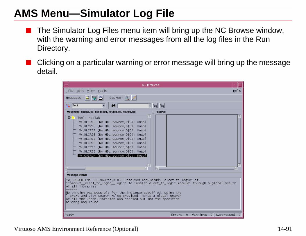
14-91
Browse window,s in the Run
g up the message
Virtuoso AMS Environment Reference (Optional)
AMS Menu—Simulator Log File■ The Simulator Log Files menu item will bring up the NC
with the warning and error messages from all the log fileDirectory.
■ Clicking on a particular warning or error message will brindetail.

14-92
AMS Menu—Simulator Log File
hand window, and
3/10/05 Virtuoso AMS Designer
■ Syntax Error messages will display the source code in the righthighlight the error location in the code.

14-93
ns for:
Virtuoso AMS Environment Reference (Optional)
AMS in ADE Simulation Options■ The Simulation—Options Menu provides access to optio
❏ Analog (Spectre)
❏ Netlister
❏ Compiler
❏ Elaborator
❏ AMS Simulator

14-94
3/10/05 Virtuoso AMS Designer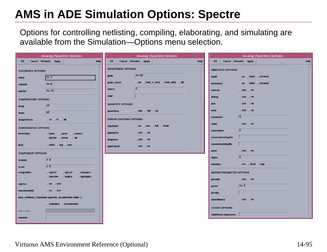
14-95
imulating are
Virtuoso AMS Environment Reference (Optional)
AMS in ADE Simulation Options: SpectreOptions for controlling netlisting, compiling, elaborating, and savailable from the Simulation—Options menu selection.

14-96
3/10/05 Virtuoso AMS Designer
14-97
g
Virtuoso AMS Environment Reference (Optional)
AMS in ADE Simulation Options: Netlistin

14-98
3/10/05 Virtuoso AMS Designer
14-99
g
Virtuoso AMS Environment Reference (Optional)
AMS in ADE Simulation Options: Compilin

14-100
3/10/05 Virtuoso AMS Designer
14-101
ing
Virtuoso AMS Environment Reference (Optional)
AMS in ADE Simulation Options: Elaborat

14-102
3/10/05 Virtuoso AMS Designer
14-103
Virtuoso AMS Environment Reference (Optional)AMS in ADE Simulation Options: AMS

14-104
3/10/05 Virtuoso AMS Designer
14-105
d actions of:
nu within the
n the Cadence®
Virtuoso AMS Environment Reference (Optional)
Review■ You have now been exposed to the options, settings, an
❏ AMS Options from both tools menu and the AMS MeHierarchy Editor
❏ AMS Netlister from the CIW window
❏ AMS Menu items, including AMS Design Prep
❏ AMS in ADE Simulation Options
■ Additional information on all these topics can be found ionline documentation.

14-106
Review
3/10/05 Virtuoso AMS Designer

14-107
Virtuoso AMS Environment Reference (Optional)LabThere is no lab for this module.

14-108
Lab
3/10/05 Virtuoso AMS Designer

Appendix A
Command Summaries


Appendix A Command Summaries
NCVlog Command Summary
Usage: ncvlog [options] source_file
Option Effect
-ALGPRIMPATH <arg> Specify a list of source files/directories of source files [with/without sectionidentifiers]
-AMS Enable ams parsing
-APPEND_LOG Append the log to an existing logfile
-CDSLIB <arg> Specifies the cds.lib file to be used
-CHECKTASKS Checks that all $tasks are predefined system tasks
-DEFINE <arg> Defines a macro
-ERRORMAX <arg> Specifies the maximum number of errors processed
-FILE <arg> Load command-line arguments from <arg>
-HDLVAR <arg> Specifies the hdl.var file to be used
-HELP Prints this message
-IEEE1364 Report errors according to the IEEE 1364 standard
-INCDIR <arg> Specifies an include directory
-LEXPRAGMA Enable Lexical Pragma processing
-LIBCELL Mark all cells with `celldefine
-LINEDEBUG Enable line debug capabilities
-LOGFILE <arg> Specifies the file to contain log information
-MESSAGES Specifies printing of informative messages
-NCERROR <arg> Increases the severity of a warning to an error
-NCFATAL <arg> Increases the severity of a warn/error to a fatal
-NEVERWARN Disables printing of all warning messages
-NOCOPYRIGHT Suppresses printing of copyright banner
-NOLINE Do not locate source line on errors
-NOLOG Suppress generation of the default logfile
-NOMEMPACK
-NOPRAGMAWARN Disable pragma related warning messages.
-NOSTDOUT Turn off output to screen
3/10/05 Cadence Design Systems, Inc. A-1

Command Summaries Appendix A
Examples:
-- To compile all the modules in source.v
% ncvlog source.v
-- To compile with informative messages
% ncvlog -messages source.v
-NOWARN <arg> Disables printing of the specified warning message
-PRAGMA Enable pragma processing
-SPECIFICUNIT <arg> Only compile the specified unit from the source file
-STATUS Dump out the status line at the end
-UNIT <arg> Specifies the unit to be compiled upon invocation
-UPCASE Changes all identifiers to upper case (case insensitive)
-UPDATE Check if unit is up-to-date before writing
-USE5X Enable full 5.X library system operation
-VERSION Prints the version number
-VIEW <arg> Specifies the view association
-WORK <arg> Specifies the work library association
-ZPARSE <arg> Enable zparsing
Option Effect
A-2 Cadence Design Systems, Inc. 3/10/05

Appendix A Command Summaries
NCVHDL Command Summary
Usage: ncvhdl [options] source_file:
Option Effect
-APPEND_LOG Causes log to be appended to an existing logfile
-CDSLIB <arg> Specifies the cds.lib file to load in
-COMPONLY <arg> Specify E, A, C, P, B only to be compiled, -COMPONLY can be givenmore than once
-ERRORMAX <arg> Specifies the maximum number of errors processed
-FILE <arg> Load command-line arguments from <arg>
-HDLVAR <arg> Specifies the hdl.var file to load in
-HELP Print this message
-LEXPRAGMA Enable Lexical Pragma processing
-LINEDEBUG Suppress optimizations which would disable single step and source linebreakpoints
-LIST Produces a VHDL source listing in the specified file
-LOGFILE <arg> Specifies the file to contain log information
-MESSAGES Specifies printing of informative messages
-NCERROR <arg> Increases the severity of a warning to an error
-NCFATAL <arg> Increases the severity of a warn/error to a fatal
-NEVERWARN Disables printing of all error messages
-NOBUILTIN Do not use any built-in IEEE operators
-NOCOPYRIGHT Suppresses printing of copyright banner
-NOLOG Suppress generation of the default logfile
-NOPRAGMAWARN Disable pragma related warning messages
-NOSTDOUT Turn off output to the screen
-NOVITALCHECK Suppresses VITAL compliance checking
-NOWARN <arg> Disables printing of the specified warning message
-PRAGMA Enable pragma processing
-RELAX Enable relaxed VHDL interpretation
-SPECIFICUNIT <arg> Only compile the specified unit from the source file
3/10/05 Cadence Design Systems, Inc. A-3

Command Summaries Appendix A
Examples:
-- To compile all the units in source.vhd
% ncvhdl source.vhd
-- To compile with informative messages
% ncvhdl -messages source.vhd
-STATUS Print out the runtime status at the end
-UNIT <arg> Specifies the unit to be compiled upon invocation
-UPDATE Don't write out .AST if identical to one on disk
-USE5X Generate library helpers for 5X library structure
-V93 Enable VHDL93 features
-VERSION Prints the version number
-VHDLVHD Serves as a modifier for the unit option, specifies that the file pointed byvhdl.vhd in the compiled unit is to be used for compilation
-WORK <arg> Specifies the VHDL WORK library
Option Effect
A-4 Cadence Design Systems, Inc. 3/10/05

Appendix A Command Summaries
NCElab Command Summary
Usage: ncelab [options] [lib.]cell[:view]:
Option Effect
-ACCESS <arg> Set default access visibility
-AFILE <arg> Access file.
-ALGPRIMPATH <arg> Specify a list of source files/directories of sourcefiles [with/without section identifiers]
-ANNO_SIMTIME Enables delay annotation at simulation time
-APPEND_LOG Append the log to an existing logfile
-BINDING <arg> Force an explicit sub-module L.C:V binding (Onlyfor Verilog® modules)
-CDSLIB <arg> Specifies the cds.lib file to be used
-COMPILE(requires -CONFFILE)
Compile the configuration file after creating it
-CONFFILE <arg> Generate a configuration file with the given name
-CONFFLAT(requires -CONFFILE)
Generate a VHDL flat configuration declaration
-CONFNAME <arg>(requires -CONFFILE)
Specify the output configuration's name (top unit forthe hierarchical case)
-COVERAGE Enable coverage instrumentation
-DELAY_MODE <arg> Delay mode {Zero, Unit, Path, Distr, None}
-DISABLE_ENHT Disable the enhanced timing features
-DISCIPLINE <arg> discipline to use for undisciplined digital wires
-DRESOLUTION use detailed discipline resolution algorithm
-EPULSE_NEG Filter cancelled events (negative pulses) to e(overrides specify block settings)
-EPULSE_NONEG Do not filter cancelled events (negative pulses) to e(overrides specify block settings)
-EPULSE_ONDETECT On-detect filtering of error pulses
-EPULSE_ONEVENT On-event filtering of error pulses
-ERRORMAX <arg> Specifies the maximum number of errors processed
-EXPAND Force expansion of Verilog vector nets
3/10/05 Cadence Design Systems, Inc. A-5

Command Summaries Appendix A
-EXTEND_TCHECK_DATA_LIMIT <arg> Relaxes tcheck data limit
-EXTEND_TCHECK_REFERENCE_LIMIT <arg> Relaxes tcheck reference limit
-FILE <arg> Load command-line arguments from <arg>
-GENAFILE <arg> Generate an access file for PLI and TCL.
-GENERIC <arg> Associates values with top level generics
-HDLVAR <arg> Specifies the hdl.var file to be used
-HELP Prints this message
-IEEE1364 IEEE 1364 lint checker
-INTERMOD_PATH Make all interconnect be fully multi-source capablewith programmable pulse limits
-LIBVERBOSE Print messages about resolving instances
-LOADPLI1 <arg> Specify the library_name:boot_routine(s) todynamically load a PLI1.0 application
-LOADVPI <arg> Specify the library_name:boot_routine(s) todynamically load a VPI application
-LOGFILE <arg> Specifies the file to contain log information
-MAXDELAYS Selects maximum delays for simulation
-MESSAGES Specifies printing of informative messages
-MINDELAYS Selects minimum delays for simulation
-NCERROR <arg> Increases the severity of a warning to an error
-NCFATAL <arg> Increases the severity of a warn/error to a fatal
-NEG_TCHK Allow negative values in SETUPHOLD &RECREM timing checks (default)
-NEVERWARN Disables printing of all warning messages
-NOCOPYRIGHT Suppresses printing of copyright banner
-NOIPD Ignore interconnect delays
-NOLOG Suppress generation of the default logfile
-NONEG_TCHK Disallow negative values in SETUPHOLD &RECREM timing checks
-NONOTIFIER Notifiers are ignored in timing checks.
-NOPARAMERR don't flag setting of undefined parameters as an error
Option Effect
A-6 Cadence Design Systems, Inc. 3/10/05

Appendix A Command Summaries
-NOSOURCE Do not check source file timestamps in update
-NOSTDOUT Turn off output to screen
-NOTIMINGCHECKS Don't execute timing checks
-NOVITALACCL Turn off VITAL acceleration
-NOWARN <arg> Disables printing of the specified warning message
-NO_SDFA_HEADER Do not print the SDF annotation header
-NO_TCHK_MSG Turn off timing check warnings
-NO_TCHK_XGEN Turn off X-generation in VITAL timing checks
-NO_VPD_MSG Turn off VITAL pathdelay warnings
-NO_VPD_XGEN Turn off X-generation in VITAL pathdelays
-NTC_VERBOSE Show limits changed by the NTC algorithm in orderto make a circuit converge
-NTC_WARN Whether to produce convergence warnings fornegative timing checks
-OMICHECKINGLEVEL <arg>
-OVERWRITE(requires -CONFFILE)
Overwrite existing configuration file of the samename
-PATHPULSE Set pulse limits according to PATHPULSE$
-PLINOOPTWARN Do not print PLI messages caused by limitedvisibility
-PLINOWARN Do not print PLI warning and error messages
-PRESERVE Preserves resolution of single driver sigs
-PROMPT(requires -CONFFILE)
Prompts to select an architecture for an entity
-PULSE_E <arg> Sets percentage of delay for pulse error limit forboth specify paths and interconnect
-PULSE_INT_E <arg> Sets percentage of delay for pulse error limit onlyfor interconnect
-PULSE_INT_R <arg> Sets percentage of delay for pulse reject limit onlyfor interconnect
-PULSE_R <arg> Sets percentage of delay for pulse reject limit forboth specify paths and interconnect
Option Effect
3/10/05 Cadence Design Systems, Inc. A-7

Command Summaries Appendix A
Examples:
-- To elaborate my_lib.top:behav
% ncelab my_lib.top:behav
% ncelab my_lib.top
% ncelab top
-- To elaborate with informative messages
% ncelab -messages my_lib.top:behav
-RELAX Enable relaxed VHDL interpretation
-SDF_CMD_FILE <arg> Specifies file of SDF annotation commands
-SDF_NOCHECK_CELLTYPE Don't check accuracy of CELLTYPE field
-SDF_NO_WARNINGS Do not report SDF warnings
-SDF_PRECISION <arg> The precision the SDF data will be modified to
-SDF_VERBOSE Include detailed information in SDF log file
-SDF_WORSTCASE_ROUNDING
-SNAPSHOT <arg> Name to use for the simulation snapshot
-STATUS Print out the runtime status at the end
-TIMESCALE <arg> Set default timescale on Verilog modules.
-TYPDELAYS Selects typical delays for simulation
-UPDATE Update design units used in the design
-USE5X4VHDL Use 5.X configurations for elaborating VHDLhierarchies
-USEARCH <arg>(requires -CONFFILE)
Specify the priority list of architectures
-V93 Enable VHDL 93 features
-VERSION Prints the version number
-VIPDMAX Select the Max. delay value forVitalInterconnectDelays
-VIPDMIN Select the Min. delay value forVitalInterconnectDelays
-WORK <arg> Specifies the WORK library
Option Effect
A-8 Cadence Design Systems, Inc. 3/10/05

Appendix A Command Summaries
NCSim Command Summary
Usage: ncsim [options] [lib.]cell[:view]:
Option Effect
-AMSLIC Use AMS license
-ANALOGCONTROL <arg> Analog Simulation Control File
-APPEND_KEY Append keystrokes to an existing keyfile
-APPEND_LOG Append the log to an existing logfile
-BATCH Run simulation in batch mode (this is the default)
-CDSLIB <arg> Specifies the cds.lib file to be used
-EPULSE_NO_MSG Suppress e-pulse error message
-ERRORMAX <arg> Specifies the maximum number of errors processed
-EXIT Always exit the simulator instead of issuing a TCL prompt
-EXTASSERTMSG Prints Extended Assert message Information
-FILE <arg> Load command-line arguments from <arg>
-GUI Enter window mode before running simulation
-HDLVAR <arg> Specifies the hdl.var file to be used
-HELP Prints this message
-INPUT <arg> Script to be executed during initialization
-KEYFILE <arg> Specifies the file to capture keyboard input
-LICQUEUE Use license queue mechanism
-LOADVPI <arg> Specify the library_name:boot_routine(s) to dynamically load a VPIapplication
-LOGFILE <arg> Specifies the file to contain log information
-MESSAGES Specifies printing of informative messages
-NCERROR <arg> Increases the severity of a warning to an error
-NCFATAL <arg> Increases the severity of a warn/error to a fatal
-NEVERWARN Disables printing of all warning messages
-NOCIFCHECK Disables constraint checking in VDA functions for increasedperformance
-NOCOPYRIGHT Suppresses printing of copyright banner
3/10/05 Cadence Design Systems, Inc. A-9

Command Summaries Appendix A
Examples:
-- To simulate the snapshot my_lib.top:snap
% ncsim my_lib.top:snap
% ncsim my_lib.top
% ncsim top
-- To simulate while writing to the log file ./ncsim.log
% ncsim -log ./ncsim.log my_lib.top:snap
-- To update the snapshot my_lib.top:snap and simulate
% ncsim -update my_lib.top:snap
-NOKEY Suppress generation of the default keyfile
-NOLICPROMOTE Do not use a NC-simulator license if single language is unavailable
-NOLOG Suppress generation of the default logfile
-NOSOURCE Do not check source file timestamps (with -UPDATE)
-NOSTDOUT Turn off output to screen
-NOWARN <arg> Disables printing of the specified warning message
-OMICHECKINGLEVEL <arg> Specify OMI checking level {Min, Std, Max}
-PLINOOPTWARN Do not print PLI messages caused by limited visibility
-PLINOWARN Do not print PLI warning and error messages
-PPE Enter PPE mode which means no active simulation just a gui
-PROFILE Generate a run time profile of the design
-PROFTHREAD Allow Threaded processes to profile
-REDMEM Use reduced memory image size
-RUN Begin simulation automatically with interactive or window mode
-STATUS Print out the runtime status at the end
-TCL Enter interactive mode before running simulation
-UNBUFFERED Do not buffer output
-UPDATE Verify snapshot and update if necessary
-VCDEXTEND Left-extend all vectors in VCD files
-VERSION Prints the version number
-XLSTYLE_UNITS XL style display of time values, same as tcl set display_unit xlstyle
Option Effect
A-10 Cadence Design Systems, Inc. 3/10/05

Appendix A Command Summaries
Verilog-A Usage and Language Summary
Description
Verilog-A is an analog hardware description language standard from Open Verilog International. It allowsanalog circuit behavior to be described at a high level of abstraction, using a language which is similar toSpectreHDL (run spectre -h spectrehdl for some details on the SpectreHDL modeling language). Behavioraldescriptions of modules/components may be instantiated in a Spectre® netlist along with regular Spectreprimitives. For more information about using the SpectreHDL product, see the SpectreHDL Referencemanual. For more information about using Verilog-A, see the Cadence Verilog-A Language Referencemanual.
Verilog-A descriptions are written in file(s) separate from the Spectre netlist file. These descriptions arewritten in modules (see the module alpha below). To include a module in the Spectre netlist, first add theline
ahdl_include "VerilogAfile.va"
to the Spectre netlist file (where VerilogAfile.va is the name of the file in which the required module isdefined). The module is instantiated in the Spectre netlist in the same manner as Spectre primitives. Forexample,
name (node1 node2) alpha arg1=4.0 arg2=2
This instantiates an element alpha, having two nodes and two parameters. Verilog-A modules can bedebugged using hdldebug. hdldebug has a GUI and a command-line mode. Please refer to the Verilog-ADebugging Tool User Guide for more information.
Module Template
The following is a Verilog-A module template:
include "discipline.h"
include "constants.h"
module alpha( n1, n2 );
electrical n1, n2;
parameter real arg1 = 2.0;
parameter integer arg2 = 0;
real local;
// this is a comment
analog begin
@ ( initial_step ) begin
// performed at the first timestep of an analysis
end
3/10/05 Cadence Design Systems, Inc. A-11

Command Summaries Appendix A
// module behavioral description
V(n1, n2) <+ I(n1, n2) * arg1;
@ ( final_step ) begin
// performed at the last time step of an analysis
end
end
endmodule
Language Summary
The following provides a summary of the Verilog-A analog hardware description language. For moreinformation refer to the Cadence Verilog-A Language Reference manual.
Analog Operators/Waveform Filters
ddt(x [,abstol] )
Differentiate x wrt time.
idt(x, ic [, assert [, abstol] ] )
Integrate x wrt time. Output = ic during dc analysis and when assertis 1.
idtmod(x, [ic [, modulus [, offset] ] ] )
Circular Integration of x wrt time. Output = ic during DC analysis.Integration is performed with given offset and modulus if specified.
transition(x [, delay [, trise [, tfall]]] )
Specify details of signal transitions. For efficient simulation, it isrecommended that x not be a continuous signal, i.e. a function of aprobe. See the Cadence Verilog-A Language Reference manual for furtherexplanation of this issue.
slew(x [, SRpos [, SRneg]])
Model slew rate behavior.
delay(x, time_delay, max_delay)
Response(t) = x(t - time_delay).
zi_nd(x, numer, denom, period, [ ttransition [,sample offset time ] ] )
z-domain filter function, numerator-denominator form.
zi_zd(x, zeros, denom, period, [ ttransition [,sample offset time ] ] )
z-domain filter function, zero-denominator form.
zi_np(x, numer, poles, period, [ ttransition [,sample offset time ] ] )
z-domain filter function, numerator-pole form.
A-12 Cadence Design Systems, Inc. 3/10/05

Appendix A Command Summaries
zi_zp(x, zeros, poles, period, [ ttransition [,sample offset time ] ] )
z-domain filter function, zero-pole form.
laplace_nd(x, numer, denom, [, abstol ] )
s-domain filter function, numerator-denominator form.
laplace_zd(x, zeros, denom, [, abstol ] )
s-domain filter function, zero-denominator form.
laplace_np(x, numer, poles, [, abstol ] )
s-domain filter function, numerator-pole form.
laplace_zp(x, zeros, poles, [, abstol ] )
s-domain filter function, zero-pole form.
Noise Functions
white_noise( power [, tag ] )
Generates white noise with given power. Noise contributions with thesame tag are combined for a module.
flicker_noise( power, exp [, tag ] )
Generates pink noise with given power at 1 Hz that varies in proportionto 1/f^exp. Noise contributions with the same tag are combined for amodule.
noise_table( vector [, tag ] )
Generates noise where power is determined by linear interpolation fromthe given vector of frequency-power pairs. Noise contributions with thesame tag are combined for a module.
AC Analysis Stimuli
ac_stim( [analysis_name [, mag ] ] )
Small signal source of specified magnitude, active for given analysis.
Analog Events
Analog events must be contained in an analog event detection statement; @(analog_event) statement.
cross(x, direction [, timetol [, abstol ] ] )
Generates an event when x crosses zero.
timer(start_time [, period] )
Set (optionally periodic) breakpoint event at time = start_time.
initial_step[ ( arg1 [, arg2 [, etc... ] ] ) ]
Generate an event at the initial step of an analysis. arg1, arg2, etc.may be any of: "dc", "tran", "ac", "pss", "noise", "pdisto", "pac","pnoise", "pxf", "sp", "tdr", "xf", "static", or "ic".
3/10/05 Cadence Design Systems, Inc. A-13

Command Summaries Appendix A
final_step[ ( arg1 [, arg2 [, etc... ] ] ) ]
Generate an event at the final step of an analysis. arg1, arg2, etc.may be any of: "dc", "tran", "ac", "pss", "noise", "pdisto", "pac","pnoise", "pxf", "sp", "tdr", "xf", "static", or "ic".
Timestep Control
bound_step(max_step)
Limit timestep, (timestep <= max_step).
last_crossing(x, direction)
Return time when expression last crossed zero in a given direction.
discontinuity(n)
Hint to simulator that discontinuity is present in nth derivative.
Simulator IO Functions
$display(argument_list)
Print data to stdout. Formatting strings may be interspersed betweenarguments/data.
$fdisplay(fptr, argument_list)
Print data to a file. Formatting strings may be interspersed betweenarguments/data.
$strobe(argument_list)
Print data to stdout. Formatting strings may be interspersed betweenarguments/data.
$fstrobe(fptr, argument_list)
Print data to a file. Formatting strings may be interspersed betweenarguments/data.
$fopen("filename")
Open a file for writing.
$fclose(fptr)
Close a file.
$finish[(n)]
Finish the simulation.
$stop[(n)]
Stop the simulation.
Simulator Environment Functions
$realtime
Returns current simulation time.
A-14 Cadence Design Systems, Inc. 3/10/05
Appendix A Command Summaries
$temperature
Returns ambient simulation temperature.
$vt
Returns thermal voltage.
$vt(temp)
Returns thermal voltage at given temp.
$analysis(analysis_string1[, analysis_string2 [, ...]])
Returns true(1) if the current analysis phase matches one of the givenanalyses strings. Valid analyses strings are; "dc", "tran", "ac","pss", "noise", "pdisto", "pac", "pnoise", "pxf", "sp", "tdr", "xf","static", or "ic".
Data Types
integer
Discrete numerical type.
real
Continuous numerical type.
Data Qualifiers
parameter
Indicates that a variable is a parameter and so may be given a differentvalue when the module is instantiated, and that it may not be assigneda different value inside the module.
Structural Statements
module_or_primative #([.param1(expr1)[,...]]) inst_name ([node1 [, ..]] );
Creates a new instance of module_or_primative called inst_name.
3/10/05 Cadence Design Systems, Inc. A-15

Command Summaries Appendix A
Updating Verilog-A Modules to Verilog-AMS
The Verilog-A language is a subset of Verilog-AMS, but some of the language elements in that subset havechanged since Verilog-A was released by itself. As a consequence, you might need to revise your Verilog-Amodules before using them as Verilog-AMS modules. The following table highlights the differences.
Feature IndependentVerilog-A Verilog-AMS Change type
Analog time $realtime $abstime new
Empty discipline Predefined as type wire Type not defined defaultdefinition
Implicit nodes `default_nodetypediscipline_identifierdefault: wire
default type: emptydiscipline, no domaintype
defaultdefinition
initial_step Default = TRAN Default = ALL defaultdefinition
final_step Default = TRAN Default = ALL defaultdefinition
$realtime $realtime:timescale =1 sec
$realtime:timescale= 'timescaledef=1n.See $abstime
definition
Discontinuity function discontinuity(x) $discontinuity(x) syntax
Limiting exponentialfunction
$limexp(expression) limexp(expression) syntax
Port branch access I(a,a)Note: Verilog-A supportsonly this form.
I(<a>)Note: This form is notsupported in Verilog-A.
syntax
Timestep control(maximum stepsize)
bound_step(const_expression)
$bound_step(expr) syntax
Continuous waveformdelay
delay() absdelay() syntax
User-defined analogfunctions
Function Analog function syntax
Discipline domain N/A, assumed continuous Now continuous (default)and discrete
Extension
A-16 Cadence Design Systems, Inc. 3/10/05

Appendix A Command Summaries
Suggestions for Updating Models
The remainder of this appendix describes some of these changes in greater detail and suggests ways ofmodifying your existing Verilog-A models so that they work in version 4.4.6 of Verilog-A and in version1.0 of Verilog-AMS. The changes recommended here might not work with 4.4.5 or earlier versions ofVerilog-A.
1. Current Probes
OVI Verilog-A 1.0 syntax for a current probe is I(a,a). OVI Verilog-AMS 2.0 changes this toI(<a>).
Suggested change: Put I(<a>) inside an `ifdef __VAMS_ENABLE__, which makes the syntaxeffective only for Verilog-AMS. For example, change
iin_val = I(vin,vin);
to
`ifdef __VAMS_ENABLE__
iin_val = I(<vin>);
`else
iin_val = I(vin,vin);
`endif
Verilog-A warning: None
Time tolerance on timerfunctions
N/A Supports additional timetolerance argument fortimer()
Extension
Time tolerance ontransition filter
N/A Supports additional timetolerance argument fortransition()
Extension
`default_nodetype `default_nodetype `default_discipline Obsolete
Generate statement generate N/A Obsolete
Null statement ; Limited to case,conditional, and eventstatements
Obsolete
Feature IndependentVerilog-A Verilog-AMS Change type
3/10/05 Cadence Design Systems, Inc. A-17

Command Summaries Appendix A
2. Analog Functions
OVI Verilog-A 1.0 declaration of an analog function is
function name;
OVI Verilog-AMS 2.0 uses the syntax
analog function name;
Suggested change: Prefix all function declarations by the word analog. For example, change
function real foo;
to
analog function real foo;
Verilog-A warning: None
3. NULL Statements
OVI Verilog-A 1.0 allows NULL statements to be used anywhere in an analog block. OVIVerilog-AMS 2.0 allows NULL statements to be used only after case statements or event controlstatements. Suggested change: remove illegal NULL statements. For example, change
begin
end;
to
begin
end
Verilog-A warning: None
4. inf Used as a Number
Spectre Verilog-A allows 'inf to be used as a number. OVI Verilog-AMS 2.0 allows 'inf to be usedonly on ranges. Suggested change: change all illegal references to 'inf to a large number such as1M. For example, change;
parameter real points_per_cycle = inf from [6:inf];
to
parameter real points_per_cycle = 1M from [6:inf];
Verilog-A warning: None
A-18 Cadence Design Systems, Inc. 3/10/05

Appendix A Command Summaries
5. Changing Delay to Absdelay
OVI Verilog-A 1.0 uses delay as the analog delay operator but OVI Verilog-AMS 2.0 usesabsdelay. Suggested change: Change delay to absdelay.
Verilog-A warning: None
6. Changing $realtime to $abstime
OVI Verilog-A 1.0 uses $realtime as absolute time but OVI Verilog-AMS 2.0 uses $abstime.Suggested change: change $realtime to $abstime.
Verilog-A warning: Yes
7. Changing bound_step to $bound_step
OVI Verilog-A 1.0 uses bound_step for step bounding but OVI Verilog-AMS 2.0 uses$bound_step. Suggested change: change bound_step to $bound_step.
Verilog-A warning: None
8. Changing Array Specifications
OVI Verilog-A 1.0 uses [] to specify arrays but OVI Verilog-AMS 2.0 uses {}. Suggested change:change [] to {}. For example, change
svcvs #(.poles([-2*`PI*bw,0])) output_filter
to
svcvs #(.poles({-2*`PI*bw,0})) output_filter
Verilog-A warning: None
9. Chained Assignments Made Illegal
Spectre-Verilog-A allows chained assignments, such as x=y=z, but OVI Verilog-AMS 2.0 makesthis illegal. Suggested change: Break chain assignments into single assignments. For example,change
x=y=z;
to
y = z; x = y;
Verilog-A warning: None
3/10/05 Cadence Design Systems, Inc. A-19

Command Summaries Appendix A
10. Real Argument Not Supported as Direction Argument
Spectre-Verilog-A allows real numbers to be used for the arguments of @cross and last_crossingbut OVI Verilog-AMS 2.0 makes this illegal. Suggested change: change the real numbers tointegers. For example, change
@(cross(V(in),1.0) begin
to
@(cross(V(in),1) begin
Verilog-A warning: None
11. $limexp Changed to limexp
OVI Verilog-A 1.0 uses $limexp, but OVI Verilog-AMS 2.0 uses limexp. Suggested change:change $limexp to limexp. For example, change
I(vp,vn) <+ is * ($limexp(vacross/$vt) - 1);
to
I(vp,vn) <+ is * (limexp(vacross/$vt) - 1);
Verilog-A warning: None
12. 'if 'MACRO is Not Allowed
Spectre-Verilog-A allows users to type 'if 'MACRO, but OVI Verilog-AMS 2.0, 1.0 and 1364 saythis is illegal. Suggested change: change 'if 'MACRO to 'if MACRO (Do not use the tick mark forthe macro). For example, change
`ifdef `CHECK_BACK_SURFACE
to
`ifdef CHECK_BACK_SURFACE
Verilog-A warning: None
13. $warning is Not Allowed
Spectre-Verilog-A supports $warning, but OVI Verilog-AMS 2.0, 1.0 and 1364 do not support thisas a standard built-in function. Suggested change: change $warning to $strobe.
Verilog-A warning: None
14. discontinuity Changed to $discontinuity
OVI Verilog-A 1.0 uses discontinuity, but OVI Verilog-AMS 2.0 uses $discontinuity. Suggestedchange: change discontinuity to $discontinuity.
Verilog-A warning: None
A-20 Cadence Design Systems, Inc. 3/10/05

Appendix B
Glossary

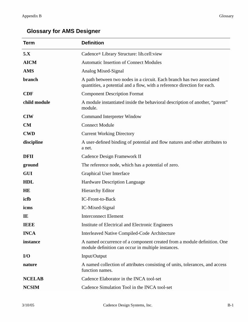
Appendix B Glossary
Glossary for AMS Designer
Term Definition
5.X Cadence® Library Structure: lib.cell:view
AICM Automatic Insertion of Connect Modules
AMS Analog Mixed-Signal
branch A path between two nodes in a circuit. Each branch has two associatedquantities, a potential and a flow, with a reference direction for each.
CDF Component Description Format
child module A module instantiated inside the behavioral description of another, “parent”module.
CIW Command Interpreter Window
CM Connect Module
CWD Current Working Directory
discipline A user-defined binding of potential and flow natures and other attributes toa net.
DFII Cadence Design Framework II
ground The reference node, which has a potential of zero.
GUI Graphical User Interface
HDL Hardware Description Language
HE Hierarchy Editor
icfb IC-Front-to-Back
icms IC-Mixed-Signal
IE Interconnect Element
IEEE Institute of Electrical and Electronic Engineers
INCA Interleaved Native Compiled-Code Architecture
instance A named occurrence of a component created from a module definition. Onemodule definition can occur in multiple instances.
I/O Input/Output
nature A named collection of attributes consisting of units, tolerances, and accessfunction names.
NCELAB Cadence Elaborator in the INCA tool-set
NCSIM Cadence Simulation Tool in the INCA tool-set
3/10/05 Cadence Design Systems, Inc. B-1
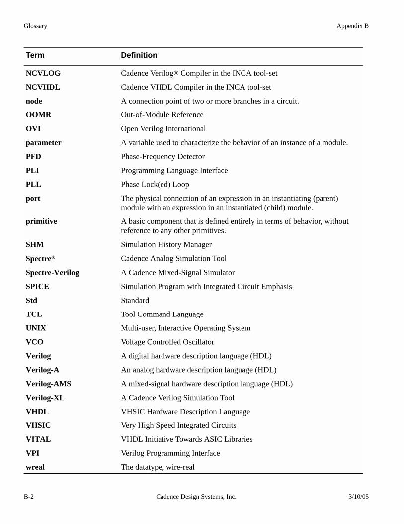
Glossary Appendix B
NCVLOG Cadence Verilog® Compiler in the INCA tool-set
NCVHDL Cadence VHDL Compiler in the INCA tool-set
node A connection point of two or more branches in a circuit.
OOMR Out-of-Module Reference
OVI Open Verilog International
parameter A variable used to characterize the behavior of an instance of a module.
PFD Phase-Frequency Detector
PLI Programming Language Interface
PLL Phase Lock(ed) Loop
port The physical connection of an expression in an instantiating (parent)module with an expression in an instantiated (child) module.
primitive A basic component that is defined entirely in terms of behavior, withoutreference to any other primitives.
SHM Simulation History Manager
Spectre® Cadence Analog Simulation Tool
Spectre-Verilog A Cadence Mixed-Signal Simulator
SPICE Simulation Program with Integrated Circuit Emphasis
Std Standard
TCL Tool Command Language
UNIX Multi-user, Interactive Operating System
VCO Voltage Controlled Oscillator
Verilog A digital hardware description language (HDL)
Verilog-A An analog hardware description language (HDL)
Verilog-AMS A mixed-signal hardware description language (HDL)
Verilog-XL A Cadence Verilog Simulation Tool
VHDL VHSIC Hardware Description Language
VHSIC Very High Speed Integrated Circuits
VITAL VHDL Initiative Towards ASIC Libraries
VPI Verilog Programming Interface
wreal The datatype, wire-real
Term Definition
B-2 Cadence Design Systems, Inc. 3/10/05