virtual reality documentation of site status: proof of concept
TRANSCRIPT

CSCE 2007 Annual General Meeting & Conference Congrès annuel et assemblée générale annuelle SCGC 2007
Yellowknife, Northwest Territories / Yellowknife, Territoires du nord-ouest June 6-9, 2007 / 6 au 9 juin 2007
GC-336-1
Virtual Reality Documentation of Site Status: Proof of Concept
L.M. Waugh1, G.L. Chisholm2, B.A.W. Nicholson3, and J.H. Rankin4 1 Professor, Department of Civil Engineering, University of New Brunswick, Fredericton, NB. 2 Project Engineer, Delphi-MRC, Halifax, NS; Formerly Research Assistant, UNB, Fredericton, NB. 3 Executive Director, Design and Construction, NB Department of Supply and Services, Fredericton, NB. 4 Associate Professor, Department of Civil Engineering, University of New Brunswick, Fredericton, NB.
ABSTRACT: The construction of the Hartland Community School has recently finished. To document the progress of this project and to experiment with virtual reality technologies, images were captured and virtual reality panoramas were generated bimonthly from July to December of 2006 and then monthly from January to March of 2007; resulting in 14 sets of 35 panoramas. This paper describes the process and workflow to capture individual images, stitch them into panoramas, and deliver them to the client within an intuitive interface. The impediments to this method of documenting construction projects fall in the following categories: capture environment, capture equipment, processing, and interface. The positive feedback from the owner includes opportunities for improvement. Direct benefits of these technologies include: recording the status of the work and saving time for project participants; indirect benefits include: avoiding legal disputes, comprehensively and graphically representing the construction operations for training purposes, and strengthening collaboration among project participants.
1. INTRODUCTION
QTVR (QuickTime Virtual Reality, 2007) has been used selectively and irregularly on construction sites for some time (e.g., Fowler 2000); however, we have not found evidence of research or development projects that used QTVR to thoroughly and regularly document construction projects. Prior to embarking on this project, we were convinced that these technologies have potential to overcome fundamental problems that have limited construction site photography in the past; furthermore, that we will be able to efficiently create a rich record of on-site information that may be intuitively navigated by an untrained user.
To test the use of periodic panoramic photography for construction administration, we chose to implement these technologies during the construction of a real project of significant size, allowing for both detailed evaluation and incremental improvement of the process, as well as meaningful feedback from the stakeholders. This work builds on a paper presented at the 2006 CSCE conference (Waugh 2006).
2. BACKGROUND
This Section begins with an overview of the Hartland School (the construction project which we documented) and then provides a summary of the research objectives and an overview of how these objectives were accomplished.

GC-336-2
2.1 The Documented Construction Project: Hartland Community School
The New Brunswick Department of Supply and Services (NB DSS) embraced this research initiative during the construction of the Hartland Community School – a 95,000 square foot state-of-the-art school designed to accommodate approximately 700 students from Kindergarten to Grade 12 in rural Hartland, New Brunswick, see Figure 1. NB DSS is the government body responsible for delivery of provincial construction projects; as such they manage the services of both consultants and contractors. NB DSS recognized that this technology had potential to monitor construction progress remotely, to promote the project to the public, and to provide a permanent record for such purposes as approving progress payments.
Figure 1: Hartland Community School, 2007 March 8
Hartland is located approximately 100 kilometres Northwest of Fredericton (the location of the NB DSS office), NB, making frequent site visits difficult for the NB DSS given the distance and staff time constraints arising from a large number of ongoing projects located throughout the province. The project was divided into two phases, Phase 1 was the foundations and structural steel and Phase 2 was the main contract. Work on Phase 2 began in April 2006 and the project was substantially complete by February 2007.
Discussions were carried out with NB DSS to determine an appropriate scope and plan for the project. These discussions addressed the following items: � Determining the appropriate number of panoramas to be recorded during each site visit such that NB
DSS budget constraints were respected, site photography could be conducted in a single day, and a representative sample of the construction work was recorded during each visit.
� Determining the optimal panorama locations within the site to provide sufficient coverage of the entire construction site while maintaining an adequate cross-section of the various unique features (e.g., elementary classrooms, high school classrooms, music and art rooms, computer labs, science labs, gymnasiums, cafeteria/auditorium, mechanical rooms, and hallways).
� Determining the appropriate time period between site visits to record the progress of the work with as much continuity as possible, yet minimize costs.
As a result of these discussions with NB DSS, it was elected to capture 35 panoramas during each site visit at locations on both levels of the building and the grounds. Fourteen site visits were made bimonthly between July and December of 2006, and then monthly between January and March of 2007.
2.2 The Research Project: Virtual Reality Panoramas
High resolution panorama technology is relatively new, particularly in the field of construction administration where we believe it is optimum to capture many panoramas in a single day and then process and deliver these panoramas within a short period of time. As such, this research and development has focused on productivity and entails objectives within three distinct areas:

GC-336-3
Photography: refining and developing a repeatable process of capturing photographs such that quality and time efficiency are maximized while faced with the many challenging constraints present on a construction site, e.g., dust, clutter, motion, poor and/or variable light conditions.
Post-processing: evaluating various hardware and software implications to develop an efficient, automated process of converting individual photographs into high-quality, error-free stitched panoramas while accurately maintaining the date and location of each.
User interface: developing and updating an interface through which an unfamiliar user may intuitively navigate between the various dates and panorama locations.
There are various technologies necessary to capture images, stitch them together, and convert the stitched image into a virtual reality panorama. Since, the scope of this paper does not permit a description of these technologies, we recommend the following references to the reader for an understanding of the required hardware and software: Panoramas.dk (2007), Virtual Parks (2007), and World Server (2007). A photograph of the type of panoramic head used for this research is shown in Figure 2.
Figure 2: Kaidan Kiwi-L Panoramic Tripod Head (Kaidan)
Research and development for this project was lead by L.M. Waugh, University of New Brunswick and his Research Assistant G.L. Chisholm. The photographic process was refined and documented at the construction site during each visit. This involved, among other things, background research of photographic theory, light metering, and depth of field to ensure that site photographs were properly exposed and focused to accommodate the actual range of distances. The variables in this analysis were camera settings such as ISO, aperture, shutter speed, flash intensity, and focus distance. The major challenge in this respect was that for any given panorama – which consists of 12 overlapping photographs rotated throughout 360 degrees – a range of distances and light levels exist. In order to produce seamless panoramas, consistent manual camera settings (i.e., ISO, aperture, shutter speed, and focus) must be used for all photographs within that panorama. As such, choosing the optimal settings to
GC-336-4
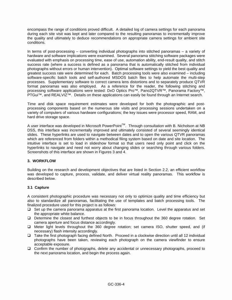
encompass the range of conditions proved difficult. A detailed log of camera settings for each panorama during each site visit was kept and later compared to the resulting panoramas to incrementally improve the quality and ultimately to deduce recommendations on appropriate camera settings for ambient site conditions.
In terms of post-processing – converting individual photographs into stitched panoramas – a variety of hardware and software implications were examined. Several panorama stitching software packages were evaluated with emphasis on processing time, ease of use, automation ability, end-result quality, and stitch success rate (where a success is defined as a panorama that is automatically stitched from individual photographs without errors or human intervention). Optimal software settings to yield the best quality and greatest success rate were determined for each. Batch processing tools were also examined – including software-specific batch tools and self-authored MSDOS batch files to help automate the multi-step processes. Supplementary software to correct camera lens distortions and to separately produce QTVR format panoramas was also employed. As a reference for the reader, the following stitching and processing software applications were tested: DxO Optics Pro™, Pano2QTVR™, Panorama Factory™, PTGui™, and REALVIZ™. Details on these applications can easily be found through an Internet search.
Time and disk space requirement estimates were developed for both the photographic and post-processing components based on the numerous site visits and processing sessions undertaken on a variety of computers of various hardware configurations; the key issues were processor speed, RAM, and hard drive storage space.
A user interface was developed in Microsoft PowerPointTM. Through consultation with B. Nicholson at NB DSS, this interface was incrementally improved and ultimately consisted of several seemingly identical slides. These hyperlinks are used to navigate between dates and to open the various QTVR panoramas which are referenced from folders within a methodical filing system based on date and site location. The intuitive interface is set to load in slideshow format so that users need only point and click on the hyperlinks to navigate and need not worry about changing slides or searching through various folders. Screenshots of this interface are shown in Figures 3 and 4.
3. WORKFLOW
Building on the research and development objectives that are listed in Section 2.2, an efficient workflow was developed to capture, process, validate, and deliver virtual reality panoramas. This workflow is described below.
3.1 Capture
A consistent photographic procedure was necessary not only to optimize quality and time efficiency but also to standardize all panoramas, facilitating the use of templates and batch processing tools. The finalized procedure used for this project is as follows:
Set up the camera panorama apparatus at the first panorama location. Level the apparatus and set the appropriate white balance.
Determine the closest and furthest objects to be in focus throughout the 360 degree rotation. Set camera aperture and focus distance accordingly.
Meter light levels throughout the 360 degree rotation; set camera ISO, shutter speed, and (if necessary) flash intensity accordingly.
Take the first photograph facing defined North. Proceed in a clockwise direction until all 12 individual photographs have been taken, reviewing each photograph on the camera viewfinder to ensure acceptable exposure.
Confirm the number of photographs, delete any accidental or unnecessary photographs, proceed to the next panorama location, and begin the process again.

GC-336-5
Figure 3: User Interface: Site Plan
3.2 Post-processing
The final post-processing procedure consists of several steps and software packages, recognizing the fact that a single stitching software application was not found which would successfully stitch all panoramas without error. Quality control measures are also outlined in this process, and an MSDOS batch file was developed to automate various steps. Before processing can begin, each panorama location must be assigned a number which corresponds to that shown on the interface schematic.
Download all photographs from the camera. Apply lens distortion correction to all photographs using the appropriate software.
Create a folder named to represent the date of the site visit (e.g., YYYYMMDD). Within this folder, create a folder for each panorama, named to represent the panorama location number as it appears on the interface schematic (e.g., 1, 2 …35). Then, place the appropriate corrected photographs in the numbered folders.
Using one of the stitching applications noted in Section 2.2 (p. 4) and a template of optimal software settings, stitch all panoramas in a single batch, outputting each panorama as a stitched JPEG image of maximum quality. Upon completion, review the results and flag any failures (i.e., panoramas with stitching errors) for further processing.
For panoramas that failed to stitch automatically, a user-assisted (manual) approach was followed to align the adjacent images through control points or other means. Output the panoramas as stitched JPEG images of maximum quality.
Convert all stitched JPEG panoramas to QTVR format at reduced quality (i.e., resolution). Perform a final quality control check at this time; if errors are detected, correct as described in the previous step.

GC-336-6
Figure 4: User Interface: Level 1
3.3 Delivery
After the processing the images from each site visit, a disk (either CD or DVD, depending on the capacity required) containing QTVR panoramas of the current and all previous site visits and the Microsoft PowerPointTM user interface file – shown in detail in Figure 3 and 4 – was prepared and delivered to the client. Because each site visit builds upon previous versions, the primary requirement at this stage is to add a dated folder to the previous disk containing the QTVR panoramas for each location. Because the user interface was developed in Microsoft PowerPointTM and uses hyperlinks to access QTVR panoramas at different dates, the interface must also be modified slightly to include the date of the latest site visit and the corresponding hyperlinks.
The Microsoft PowerPointTM interface has been described in previous sections and Figures 3 and 4 illustrate its functionality. Again, the disk delivered to the client contains this Microsoft PowerPointTM file as well as a folder for all site visits to date (each of these folders contains the 35 QTVR panoramas captured on that date).
4. CHALLENGES OVERCOME
Table 1 describes challenges that were overcome during the course of the project. Several of these are ongoing by nature and hence will require continuing attention, such as working around on-site obstructions and improving productivity through automation and streamlining methods.

GC-336-7
Table 1: Challenges C
aptu
re E
nviro
nmen
t Depth of field/exposure settings: Determining these was inordinately time consuming, initially. Natural lighting: Using natural lighting alone can result in two problems: (a) during the stage of construction when the building is closed in, but permanent lighting has not been installed, there is often inadequate light, (b) relying heavily on natural lighting precludes the possibility of pre-defining the exposure settings prior to arriving on site.
Flash lighting: Although flash lighting solves the previous problem, it introduces the next problem (dust) and it can also adversely affect stitching.
Dust: When a flash is used, dust particles in the air can greatly reduce the panorama quality. Motion: Each picture overlaps the next by approximately one third. If an object in this overlap region moves between the times when the overlapping images are captured, then the ability to automatically stitch the images is impaired. Objects found to cause this problem included: clouds in an otherwise clear sky as well as people or equipment in a busy area.
Hallways: This is the most difficult situation to find the optimum exposure settings and is the most difficult to stitch, due to both near and distant of objects as well as the wall/ceiling patterns.
Obstructions: On rare occasions, the camera could not be set up in the desired location, since materials were stored there. More frequently, materials or equipment obstructed the view.
Access: Two (of 490) panoramas could not be captured, since wet cement had been applied to the complete floor of these rooms in preparation for laying tiles.
Cap
ture
Equ
ipm
ent
Stability: A heavy and sturdy tripod is essential to avoid movement of the camera during the capture of individual images at a location.
No-parallax point of the lens: When rotating the camera to take the next image it must rotate around this precise point, otherwise parallax will occur and will make stitching difficult (even if manual). Parallax is the apparent shift of an object against a background. This point is also referred to in the literature as the nodal point or the focal point of the lens.
Flash location: By raising the flash to about 30 cm above the lens, we were able to solve the dust problem mentioned above, but this added an eccentricity to the panoramic head and reduced the stability of the camera.
Flash intensity: Many rooms were large, so a high intensity flash was required. Flash batteries: The power requirements were substantial, since we took 420 images per visit. Memory: Also due to the number of images, we needed to have several GB of camera memory. Rapid changes in equipment and software: After each set of panoramas were produced we found ourselves purchasing new equipment and testing new software; this rapid evolution of the work flow greatly reduced our short-term productivity, but has been worthwhile.
Proc
essi
ng
Processing equipment: Post-processing was very slow without a fast processor and at least one gigabyte of RAM; hard drive (and backup) space is required for individual, corrected, temporary, and stitched images, as well as for virtual reality files.
Optical corrections: Lens that cost less than approximately $2500, produce significant optical distortions, which often affect the ability of software to stitch images.
Automation: For speed, it was essential to find means of batch processing both the stitching of images and the conversion of images into QTVR movies, as well as to integrate these tools.
Software alternatives: It was very time consuming to gain a detailed understanding of very different software alternatives for correcting the images, stitching the panoramas, and integrating the interface.
Workflow/quality control: To streamline the process, workflow and QC forms were developed.
Inte
rfac
e Intuitive navigation: Microsoft PowerPointTM schematics; hotspots are an alternative means of moving from a panorama to an adjacent panorama; however, hotspot navigation alone would not be efficient, if the user wanted to jump from one end of the building to the other.
User software: Lack of software applications can be a barrier for use of the interface, if they are not inexpensive nor readily available (preferably free and a component of MS WindowsTM).

GC-336-8
5. CLIENT FEEDBACK
Feedback from a number of staff at NB DSS was conveyed through the third author, B.A.W. Nicholson. Two feedback sessions were held, the first in September and the second in December. Although the format of these sessions was a general discussion, for brevity, the feedback is presented here under four questions. A final feedback session is planned for April; in addition to NB DSS, the general contractor, Springhill Construction Limited, and the prime designer, Goguen and Company Limited, will be invited.
What is your impression of the pilot project to date? � We are generally impressed and intrigued. � The interface is intuitive. � A few people with older computers (i.e., slower processors or minimal RAM) were frustrated by the
time it took to view the panoramas or by their inability to view the panoramas. � The panoramas document a clear record of what happened; they could be used help avoid claims
which arise from disagreements about what actually happened. � These technologies have archival and documentation purposes for us. � Virtual representation by panoramas appears to give a greater context and continuity to the spaces
than still pictures.
For whom is it useful in the short term? � These technologies do not add value for our staff who are on the project everyday. They are useful
for other managers, to review and track project progress, particularly if the manager is at a distance from the work site.
� They could also be useful information for the public and other government departments, e.g., the Department of Education.
� They could be useful for the consulting team to review work progress between scheduled visits and to monitor the impacts of requests for information and contemplated change orders.
What would you do differently? � We would start taking pictures at the beginning of the site work. � We would take 20 to 25 panoramas, rather than 35; this would adequately represent the status of a
project of this size and building type. We would take fewer panoramas early in the project and more later, rather than rigidly using the same 35 locations; the locations should evolve as the project progresses.
� We might have timed the panoramas to be available for biweekly job meetings. � We might be interested in having one of our on-site staff capture the initial images for subsequent
processing by you; this could be more cost effective and therefore feasible for more projects, particularly distant projects.
� Why not have a faster turn-around time between capture and delivery of the DVD to us? � Why not deliver the panoramas via the web?
What improvements do you suggest for the interface? � Make it bilingual. � Create the ability to jump from a panorama at one location to an adjacent panorama, without
returning to the schematic. � Create the ability to jump from the current pan and zoom of one panorama to the same pan and zoom
of a panorama on a different date, but at the same location. � Create a “notes” link for panoramas where additional information could be added, such as the project
percent complete. � Could you get this on a Blackberry?
GC-336-9
6. APPLICATION, EXTENSIONS, AND POTENTIAL
In summary, we identify the following applications for these technologies: � Saving project participants the time and cost of travelling to the work site. The savings might arise
from a remote expert not having to travel by plane and car to the site, or (after these technologies are refined) the savings might arise from the members of a job meeting being able to view the work from within the job office (a few minutes walk from the work face).
� Periodically recording the status of the work, for purposes such as approval of progress claims, adherence to schedule commitments, or “photographic as-builts.” Here the emphasis is not on “assessing the progress without visiting the site,” rather the emphasis is on recording the status for future reference.
� Avoiding claims that are based on disagreements on site progress, by having a vivid record. � Comprehensively and graphically representing the construction workflow and sequencing as a
comparison when monitoring progress on other similar projects and as a tool for training junior construction engineers.
� Strengthening collaboration and problem solving among project participants, particularly on projects with schedule constraints.
The suggested improvements listed in Section 5 (Client Feedback) are our short-term objectives. A secondary objective is to investigate the complementary use of photogrammetry techniques to create a three dimensional model of a space based on panoramas taken from two known locations (e.g., one panorama taken from one meter above the other).
This pilot project has demonstrated the potential for use of virtual reality panorama technologies to record the status on construction sites. We are very optimistic about further application and development of the processes and technologies that we have employed.
ACKNOWLEDGEMENTS
We would like to express our appreciation to a several individuals and organizations. R. Daigle and the NB DSS Construction Services Branch provided us with valuable feedback on how to improve our end product. R.B. Anderson, S. King, and R. Mazerolle from Springhill Construction Limited gave us unrestricted access to the site, without which this project would not have been possible. E. Goguen provided the schematics that became a fundamental component of our user interface. J.B.L. Robinson of Delphi-MRC Limited also provided helpful advice during the project. An NSERC USRA grant, the NB DSS, the M. Patrick Gillin Chair in Construction Engineering and Management, and Delphi-MRC Limited each funded a portion of G.L. Chisholm’s time during the project.
REFERENCES All websites were last visited on 2007 March 24.
Delphi-MRC. 2007. Delphi-MRC Limited, http://www.delphimrc.com/ Goguen. 2007. Goguen and Company Limited, http://www.goguenarch.com/ Fowler. 2000. Guyer W. Fowler School Construction Journal,
http://web.maynard.ma.us/history/schools/nms/construction.htm Kaidan. 2007. “Kaidan Kiwi-L Panoramic Tripod Head, http://www.kaidan.com/pdf/KiWi-
L_Spec_Sheet.pdf NB DSS. 2007. New Brunswick Department of Supply and Services, http://www.gnb.ca/0099/index-e.asp Panoramas.dk. 2007. How to do Panoramas, http://www.panoramas.dk/panorama/index.html QuickTime. 2007. http://en.wikipedia.org/wiki/Quicktime Virtual Parks. 2007. Resources for Authoring QuickTime VR Panoramas,
http://www.virtualparks.org/html/qtvr-links.html Waugh, L.M. 2006. Construction Site Photography: Virtual Reality vs. The Focus Context Problem.
CSCE First International Construction Specialty Conference, Canadian Society for Civil Engineering, Calgary, AB, Canada, CT-092.
World Server. 2007. http://www.worldserver.com/turk/quicktimevr/QTVRlinks.html