virtual reality applied to biomedical engineering
TRANSCRIPT

BACHELOR THESIS
Biomedical & Mechanical Engineering
VIRTUAL REALITY APPLIED TO BIOMEDICAL ENGINEERING
Conversion of medical images to 3D models and their implementation to a
virtual reality app designed for surgical planning of congenital cardiac defects
Project & Annex
Authors: Bernat Cunill Fulquet & Arnau Mora Tarragona Director: Jordi Torner Ribe Co-Director: Francesc Alpiste Penalba
January 2018


Virtual Reality applied to biomedical engineering
i

Project
ii
ABSTRACT
Nowadays, virtual reality is on trend and it is spreading throughout the medical field, making possible
the creation of huge amounts of applications designed to train doctors and treat patients in a more
efficient way, as in optimizing the surgical planning processes. The medical need and the aim of this
project is to optimize the surgical planning process for congenital heart defects, which comprised the
3D reconstruction of the patient’s heart and its integration in the VR app. Following this line, it has
been a combination of 3D modelling images of hearts thanks to the Hospital Sant Joan de Déu and the
application design with the software Unity 3D thanks to the company VISYON. Improvements were
accomplished regarding the used software for the segmentation and reconstruction, and basic
functionalities where achieved, such as import, move, rotate, 3D screenshots of the cardiac organ and,
thus, have a better understanding of the treated congenital heart disease. The result has been the
creation of an ideal process, in which the 3D reconstruction has achieved its rapidity and accuracy, the
very simple importing method to the designed app, and the Virtual Reality app which allows an
attractive and intuitive interaction, thanks to an immersive and realistic experience to adjust to the
efficiency and precision requirements demanded in the medical field.

Virtual Reality applied to biomedical engineering
iii
RESUM
Actualment, la realitat virtual esta sent tendència i s'està expandint a l'àmbit mèdic, fent possible
l'aparició de nombroses aplicacions dissenyades per entrenar metges i tractar pacients de forma més
eficient, així com optimitzar els processos de planificació quirúrgica. La necessitat mèdica i objectiu
d'aquest projecte és fer òptim el procés de planificació quirúrgica per a cardiopaties congènites, que
compren la reconstrucció en 3D del cor del pacient i la seva integració en una aplicació de realitat
virtual. Seguint aquesta línia s’ha combinat un procés de modelat 3D d’imatges de cors obtinguts
gracies al Hospital Sant Joan de Déu i el disseny de l’aplicació mitjançant el software Unity 3D gracies a
l’empresa VISYON. S'han aconseguit millores en quant al software emprat per a la segmentació i
reconstrucció, i s’han assolit funcionalitats bàsiques a l’aplicació com importar, moure, rotar i fer
captures de pantalla en 3D de l'òrgan cardíac i així, entendre millor la cardiopatia que s’ha de tractar.
El resultat ha estat la creació d'un procés òptim, en el que la reconstrucció en 3D ha aconseguit ser
ràpida i precisa, el mètode d’importació a l’app dissenyada molt senzill, i una aplicació que permet una
interacció atractiva i intuïtiva, gracies a una experiència immersiva i realista per ajustar-se als
requeriments d'eficiència i precisió exigits en el camp mèdic.

Project
iv
RESUMEN
Actualmente, la realidad virtual está siendo tendencia y se está expandiendo en el ámbito médico,
haciendo posible la aparición de numerosas aplicaciones diseñadas para entrenar médicos y tratar
pacientes de forma más eficiente, así como optimizar los procesos de planificación quirúrgica. La
necesidad médica y objetivo de este proyecto es hacer óptimo el proceso de planificación quirúrgica
para cardiopatías congénitas, que comprende la reconstrucción en 3D del corazón del paciente y su
integración en una aplicación de realidad virtual. Siguiendo esta línea se ha combinado un proceso de
modelado 3D de imágenes de corazones obtenidos gracias al Hospital Sant Joan de Déu y el diseño de
la aplicación mediante el software Unity 3D gracias a la empresa VISYON. Se han logrado mejoras en
cuanto al software empleado para la segmentación y reconstrucción, y se han logrado funcionalidades
básicas en la aplicación como importar, mover, rotar y hacer capturas de pantalla en 3D del órgano
cardíaco y así, entender mejor la cardiopatía que se debe tratar. El resultado ha sido la creación de un
proceso óptimo, en el que la reconstrucción en 3D ha conseguido ser rápida y precisa, el método de
importación a la app diseñada muy sencillo, y una aplicación que permite una interacción atractiva e
intuitiva, gracias a una experiencia inmersiva y realista para ajustarse a los requerimientos de eficiencia
y precisión exigidos en el campo médico.

Virtual Reality applied to biomedical engineering
v
Project
vi
AKNOWLEDGEMENTS
We would like to thank all the people that has helped this project become real, despite all the issues
that have appeared during the process.
In first place, thanks to Visyon for providing us with the HTC Vive set so that we could work with it and
test with ease any improvement in the app. From there thanks to Iñigo Gainza for managing and
helping us direct the project, as well as Josep Lorente for his tireless patience and kindness towards to
programming part.
Thanks to our tutors Jordi Torner and Francesc Alpiste for devoting time and helping to guide us
throughout the project.
In the other hand, thanks for the help from Hospital Sant Joan de Déu by Alex Perez and Joan Sanchez,
for lending us the DICOM images for the project, and also inviting us to the hospital to observe and ask
for possible needs for the doctors.
Finally, thanks to family and friends that have been there in the hardest moments, giving us strength
to carry on and finish our job.

Virtual Reality applied to biomedical engineering
vii

Project
viii

Virtual Reality applied to biomedical engineering
ix
Index
ABSTRACT __________________________________________________________ II
RESUM _____________________________________________________________ III
RESUMEN __________________________________________________________ IV
AKNOWLEDGEMENTS _________________________________________________ VI
1. INTRODUCTION ________________________________________________ 17
1.1. Context ................................................................................................................... 17
1.2. Motivation .............................................................................................................. 17
1.3. Project objectives ................................................................................................... 18
1.4. Significance of the project ..................................................................................... 18
2. STATE OF THE ART: VIRTUAL REALITY _______________________________ 19
2.1. Definition ................................................................................................................ 19
2.2. History .................................................................................................................... 20
2.3. Present ................................................................................................................... 21
2.3.1. Non-Immersive Virtual Reality Environments ..................................................... 21
2.3.2. Semi-Immersive Virtual Reality Environments .................................................... 21
2.3.3. CAVE Fully Immersive Virtual Reality ................................................................... 22
2.3.4. Collaborative Virtual Environments ..................................................................... 22
2.4. Device election ....................................................................................................... 22
2.4.1. Competitors .......................................................................................................... 23
2.5. Uses of Virtual Reality ............................................................................................ 26
2.6. Medical use of Virtual Reality ................................................................................ 26
3. MEDICAL NEEDS: SURGICAL PLANNING FOR CONGENITAL HEART DEFECTS 29
3.1. Human heart anatomy ........................................................................................... 29
3.2. Human heart function............................................................................................ 30
3.3. Congenital heart defects ........................................................................................ 31
3.3.1. Aortic Valve Stenosis (AVS) .................................................................................. 31
3.3.2. Atrial Septal Defect (ASD) ..................................................................................... 31
3.3.3. Coarctation of the Aorta (CoA) ............................................................................. 32
3.3.4. Complete Atrioventricular Canal defect (CAVC) .................................................. 32
3.3.5. Patent Ductus Arteriosus (PDA) ........................................................................... 33
3.3.6. Tetralogy of Fallot (ToF) ....................................................................................... 33

Project
x
4. MEDICAL IMAGES RECONSTRUCTION _______________________________ 35
4.1. Medical imaging ..................................................................................................... 36
4.1.1. Conventional radiography .................................................................................... 36
4.1.2. Computed tomography (CT) ................................................................................. 37
4.1.3. Magnetic resonance imaging (MRI) ...................................................................... 37
4.1.4. 3D angiography ..................................................................................................... 38
4.1.5. Echocardiogram .................................................................................................... 38
4.2. Medical image file formats .................................................................................... 39
4.3. Image segmentation .............................................................................................. 40
4.3.1. Thresholding.......................................................................................................... 40
4.3.2. Region based segmentation (Region Growing) .................................................... 41
4.4. Geometric reconstruction & volume rendering ................................................... 42
4.5. Mesh processing .................................................................................................... 43
5. PROJECT PLANNING _____________________________________________ 45
5.1. Methodology ......................................................................................................... 45
5.2. Planning ................................................................................................................. 46
5.2.1. Gantt Chart ............................................................................................................ 47
6. SEGMENTATION PREPARATION ___________________________________ 51
6.1. Analysis and Selection of the segmentation program .......................................... 51
6.2. 3D Models & Design requirements ....................................................................... 53
7. SEGMENTATION PROCESS ________________________________________ 55
7.1. OsiriX ...................................................................................................................... 55
7.2. Mimics Medical ...................................................................................................... 59
7.3. Blender ................................................................................................................... 71
8. VIRTUAL REALITY APPLICATION ___________________________________ 75
8.1. Game engine .......................................................................................................... 75
8.2. Development of the application ............................................................................ 76
8.2.1. Scene ..................................................................................................................... 77
8.2.2. Player ..................................................................................................................... 77
8.2.3. Menu ..................................................................................................................... 79
8.3. How to use ............................................................................................................. 85
8.3.1. Preparation ........................................................................................................... 85
8.3.2. Game Start ............................................................................................................ 85
8.3.3. Model import ........................................................................................................ 86

Virtual Reality applied to biomedical engineering
xi
8.3.4. Use Interactions .................................................................................................... 87
CONCLUTIONS ______________________________________________________ 91
BUDGET ___________________________________________________________ 95
9. BIBLIOGRAPHY _________________________________________________ 99
ANNEX A: SCRIPTS USED _____________________________________________ 101
A1. ControllerFunctions ............................................................................................. 101
A2. ImportManager ....................................................................................................... 111
A3. Screenshot ............................................................................................................... 113

Project
xii
Figure Index FIGURE 1 EXAMPLE OF PANORAMIC PAINTING (SOURCE: VIRTUAL REALITY SOCIETY) ................................................................. 20
FIGURE 2 THE SENSORAMA (SOURCE: VIRTUAL REALITY SOCIETY) .......................................................................................... 20
FIGURE 3 VIRTUALITY: VR ARCADE (SOURCE: TESLASUIT) ..................................................................................................... 21
FIGURE 4 CAVE VR SPACE (SOURCE: AVICVISION) .............................................................................................................. 22
FIGURE 5 HTC VIVE MAIN CONFIGURATION (SOURCE: MIGHTY APE) ..................................................................................... 23
FIGURE 6 OCULUS RIFT SET (SOURCE: VR HEADS) .............................................................................................................. 23
FIGURE 7 SAMSGUNG'S GEAR VR (SOURCE: SAMSUNG) ...................................................................................................... 24
FIGURE 8 GOOGLE CARDBOARD (SOURCE: GOOGLE STORE) ................................................................................................. 24
FIGURE 9 MEDICAL TRAINING WITH VR DEVICE (SOURCE: MEDICAL FUTURIST) ........................................................................ 27
FIGURE 10 HEART ANATOMY (SOURCE: LIVESCIENCE) .......................................................................................................... 29
FIGURE 11 HEART FUNCTION (SOURCE: LIVESCIENCE) .......................................................................................................... 30
FIGURE 12 AORTIC VALVE STENOSIS (SOURCE: AMERICAN HEART ASSOCIATION) ..................................................................... 31
FIGURE 13 ATRIAL SEPTAL DEFECT (SOURCE: AMERICAN HEART ASSOCIATION) ....................................................................... 31
FIGURE 14 COARCTATION OF THE AORTA (SOURCE: AMERICAN HEART ASSOCIATION) .............................................................. 32
FIGURE 15 COMPLETE ATRIOVENTRICULAR CANAL DEFECT (SOURCE: AMERICAN HEART ASSOCIATION)........................................ 32
FIGURE 16 PATENT DUCTUS ARTERIOSUS (SOURCE: AMERICAN HEART ASSOCIATION) .............................................................. 33
FIGURE 17 TETRALOGY OF FALLOT (SOURCE: AMERICAN HEART ASSOCIATION)........................................................................ 33
FIGURE 18 HEART SEGMENTATION (SOURCE: SCREENSHOT MIMICS MEDICAL) ........................................................................ 35
FIGURE 19 DOCTOR LOOKING MEDICAL IMAGES (SOURCE: IBM) ........................................................................................... 35
FIGURE 20 3D RECONSTRUCTION (SOURCE: SCREENSHOT MIMICS MEDICAL) .......................................................................... 35
FIGURE 21 MESH (SOURCE: SCREENSHOT BLENDER) ........................................................................................................... 35
FIGURE 22 COMPUTED TOMOGRAPHY (SOURCE: LIFEBRIDGE HEALTH) .................................................................................. 37
FIGURE 23 OSIRIX SEGMENTATION STEP (SOURCE: SCREENSHOT OSIRIX) ............................................................................... 56
FIGURE 24 OSIRIX SEGMENTATION STEP (SOURCE: SCREENSHOT OSIRIX) ............................................................................... 56
FIGURE 25 OSIRIX SEGMENTATION STEP (SOURCE: SCREENSHOT OSIRIX) ............................................................................... 57
FIGURE 26 OSIRIX SEGMENTATION STEP (SOURCE: SCREENSHOT OSIRIX) ............................................................................... 57
FIGURE 27 OSIRIX VOLUME RENDERING (SOURCE: SCREENSHOT OSIRIX) ................................................................................ 58
FIGURE 28 OSIRIX RENDERING TOOL (SOURCE: SCREENSHOT OSIRIX) .................................................................................... 58
FIGURE 29 MIMICS SEGMENTATION STEP (SOURCE: SCREENSHOT MIMICS) ............................................................................ 59
FIGURE 30 MIMICS SEGMENTATION STEP (SOURCE: SCREENSHOT MIMICS) ............................................................................ 60
FIGURE 31 MIMICS SEGMENTATION STEP (SOURCE: SCREENSHOT MIMICS) ............................................................................ 60
FIGURE 32 MIMICS SEGMENTATION STEP (SOURCE: SCREENSHOT MIMICS) ............................................................................ 61
FIGURE 33 MIMICS SEGMENTATION STEP (SOURCE: SCREENSHOT MIMICS) ............................................................................ 61
FIGURE 34 MIMICS SEGMENTATION STEP (SOURCE: SCREENSHOT MIMICS) ............................................................................ 62
FIGURE 35 MIMICS SEGMENTATION STEP (SOURCE: SCREENSHOT MIMICS) ............................................................................ 62
FIGURE 36 MIMICS SEGMENTATION STEP (SOURCE: SCREENSHOT MIMICS) ............................................................................ 63
FIGURE 37 MIMICS SEGMENTATION STEP (SOURCE: SCREENSHOT MIMICS) ............................................................................ 63
FIGURE 38 MIMICS SEGMENTATION STEP (SOURCE: SCREENSHOT MIMICS) ............................................................................ 64
FIGURE 39 MIMICS SEGMENTATION (SOURCE: SCREENSHOT MIMICS) ................................................................................... 64

Virtual Reality applied to biomedical engineering
xiii
FIGURE 40 MIMICS SEGMENTATION RESULT WITH AND WITHOUT PATHOLOGY (SOURCE: SCREENSHOT MIMICS) ............................ 65
FIGURE 41 MIMICS SEGMENTATION RESULT (SOURCE: SCREENSHOT MIMICS) ........................................................................ 65
FIGURE 42 MIMICS SEGMENTATION TOOL (SOURCE: SCREENSHOT MIMICS) ........................................................................... 66
FIGURE 43 MIMICS SEGMENTATION TOOL (SOURCE: SCREENSHOT MIMICS) ........................................................................... 66
FIGURE 44 MIMICS SEGMENTATION TOOL (SOURCE: SCREENSHOT MIMICS) ........................................................................... 67
FIGURE 45 MIMICS SEGMENTATION TOOL (SOURCE: SCREENSHOT MIMICS) ........................................................................... 67
FIGURE 46 MIMICS SEGMENTATION TOOL (SOURCE: SCREENSHOT MIMICS) ........................................................................... 68
FIGURE 47 MORPHOLOGY OPERATIONS (SOURCE: MIMICS MEDICAL GUIDE) .......................................................................... 68
FIGURE 48 MIMICS SEGMENTATION TOOL (SOURCE: SCREENSHOT MIMICS) ........................................................................... 69
FIGURE 49 MIMICS SEGMENTATION TOOL (SOURCE: SCREENSHOT MIMICS) ........................................................................... 69
FIGURE 50 MIMICS EXPORT PARAMETERS (SOURCE: SCREENSHOT MIMICS) ............................................................................ 70
FIGURE 51 BLENDER SMOOTHING STEP (SOURCE: SCREENSHOT BLENDER) ............................................................................... 71
FIGURE 52 BLENDER SMOOTHING STEP (SOURCE: SCREENSHOT BLENDER) ............................................................................... 72
FIGURE 53 BLENDER SMOOTHING STEP (SOURCE: SCREENSHOT BLENDER) ............................................................................... 72
FIGURE 54 BLENDER SMOOTHING STEP (SOURCE: SCREENSHOT BLENDER) ............................................................................... 73
FIGURE 55 UNITY ENGINE LOGO (SOURCE: UNITY3D.COM) .................................................................................................. 75
FIGURE 56 PANORAMIC SCENE VIEW FROM THE APPLICATION ................................................................................................ 77
FIGURE 57 CONTROLLER'S MAIN MENU ............................................................................................................................ 79
FIGURE 58 IMPORT ICON ................................................................................................................................................ 80
FIGURE 59 INTERACTION'S ICON ....................................................................................................................................... 80
FIGURE 60 ROTATION ICON ............................................................................................................................................. 81
FIGURE 61 SCALE ICON ................................................................................................................................................... 81
FIGURE 62 MOVEMENT ICON .......................................................................................................................................... 82
FIGURE 63 SCREEN CAPTURE ICON ................................................................................................................................... 82
FIGURE 64 CONTROLS MENU ........................................................................................................................................... 83
FIGURE 65 OPTIONS ICON ............................................................................................................................................... 83
FIGURE 66 GUIDE ICON .................................................................................................................................................. 84
FIGURE 67 GUIDE MENU................................................................................................................................................. 84
FIGURE 68 BACK BUTTON ICON ........................................................................................................................................ 84
FIGURE 69 REPRESENTATION OF OBJECT SAVING ................................................................................................................. 85
FIGURE 70 IMPORT MENU. EACH CUBE MATCHES THE MODEL NAMED WITH THE SAME NUMBER .................................................. 86
FIGURE 71 IMPORT MENU. EACH CUBE MATCHES THE MODEL NAMED WITH THE SAME NUMBER .................................................. 86
FIGURE 70 IMPORT MENU. EACH CUBE MATCHES THE MODEL NAMED WITH THE SAME NUMBER .................................................. 86
FIGURE 71 IMPORT MENU. EACH CUBE MATCHES THE MODEL NAMED WITH THE SAME NUMBER .................................................. 86
FIGURE 70 IMPORT MENU. EACH CUBE MATCHES THE MODEL NAMED WITH THE SAME NUMBER .................................................. 86
FIGURE 71 IMPORT MENU. EACH CUBE MATCHES THE MODEL NAMED WITH THE SAME NUMBER .................................................. 86
FIGURE 70 IMPORT MENU. EACH CUBE MATCHES THE MODEL NAMED WITH THE SAME NUMBER .................................................. 86
FIGURE 71 IMPORT MENU. EACH CUBE MATCHES THE MODEL NAMED WITH THE SAME NUMBER .................................................. 86
FIGURE 70 IMPORT MENU. EACH CUBE MATCHES THE MODEL NAMED WITH THE SAME NUMBER .................................................. 86
FIGURE 71 IMPORT MENU. EACH CUBE MATCHES THE MODEL NAMED WITH THE SAME NUMBER .................................................. 86
FIGURE 70 IMPORT MENU. EACH CUBE MATCHES THE MODEL NAMED WITH THE SAME NUMBER .................................................. 86

Project
xiv
FIGURE 71 IMPORT MENU. EACH CUBE MATCHES THE MODEL NAMED WITH THE SAME NUMBER ................................................. 86
FIGURE 70 IMPORT MENU. EACH CUBE MATCHES THE MODEL NAMED WITH THE SAME NUMBER ................................................. 86
FIGURE 71 IMPORT MENU. EACH CUBE MATCHES THE MODEL NAMED WITH THE SAME NUMBER ................................................. 86
FIGURE 70 IMPORT MENU. EACH CUBE MATCHES THE MODEL NAMED WITH THE SAME NUMBER ................................................. 86
FIGURE 71 IMPORT MENU. EACH CUBE MATCHES THE MODEL NAMED WITH THE SAME NUMBER ................................................. 86
FIGURE 72 LOADED HEART IN THE CENTER OF THE ROOM ...................................................................................................... 86
FIGURE 72 LOADED HEART IN THE CENTER OF THE ROOM ...................................................................................................... 86
FIGURE 72 LOADED HEART IN THE CENTER OF THE ROOM ...................................................................................................... 86
FIGURE 72 LOADED HEART IN THE CENTER OF THE ROOM ...................................................................................................... 86
FIGURE 72 LOADED HEART IN THE CENTER OF THE ROOM ...................................................................................................... 86
FIGURE 72 LOADED HEART IN THE CENTER OF THE ROOM ...................................................................................................... 86
FIGURE 72 LOADED HEART IN THE CENTER OF THE ROOM ...................................................................................................... 86
FIGURE 72 LOADED HEART IN THE CENTER OF THE ROOM ...................................................................................................... 86
FIGURE 73 INTERACTIONS MENU...................................................................................................................................... 87
FIGURE 74 INTERACTIONS MENU...................................................................................................................................... 87
FIGURE 75 AVAILABLE MODEL ROTATION........................................................................................................................... 87
FIGURE 75 AVAILABLE MODEL ROTATION........................................................................................................................... 87
FIGURE 75 AVAILABLE MODEL ROTATION........................................................................................................................... 87
FIGURE 75 AVAILABLE MODEL ROTATION........................................................................................................................... 87
FIGURE 75 AVAILABLE MODEL ROTATION........................................................................................................................... 87
FIGURE 75 AVAILABLE MODEL ROTATION........................................................................................................................... 87
FIGURE 75 AVAILABLE MODEL ROTATION........................................................................................................................... 87
FIGURE 75 AVAILABLE MODEL ROTATION........................................................................................................................... 87
FIGURE 76 PLAYER VISION INSIDE THE GAME ...................................................................................................................... 88
FIGURE 76 PLAYER VISION INSIDE THE GAME ........................................................................ ¡ERROR! MARCADOR NO DEFINIDO.
FIGURE 76 PLAYER VISION INSIDE THE GAME ........................................................................ ¡ERROR! MARCADOR NO DEFINIDO.
FIGURE 76 PLAYER VISION INSIDE THE GAME ........................................................................ ¡ERROR! MARCADOR NO DEFINIDO.

Virtual Reality applied to biomedical engineering
xv
FIGURE 76 PLAYER VISION INSIDE THE GAME ......................................................................... ¡ERROR! MARCADOR NO DEFINIDO.
FIGURE 76 PLAYER VISION INSIDE THE GAME ......................................................................... ¡ERROR! MARCADOR NO DEFINIDO.
FIGURE 76 PLAYER VISION INSIDE THE GAME ......................................................................... ¡ERROR! MARCADOR NO DEFINIDO.
FIGURE 76 PLAYER VISION INSIDE THE GAME ......................................................................... ¡ERROR! MARCADOR NO DEFINIDO.

Project
xvi

Virtual Reality applied to biomedical engineering
17
1. INTRODUCTION
1.1. Context
In a constantly growing world, technology evolves at vertiginous speeds. Every time a question
appears, there’s an answer to be discovered, and this has been happening for a long time. During
human existence, there have been innumerable amounts of inventions that have represented a huge
step for humanity. This has never stopped happening yet, but it is true that every time it gets harder
to innovate and be creative.
Many of those inventions were considered impossible or unimaginable before they became a real
thing, just like in the case of Virtual Reality. This term appeared with the idea to create a virtual space
where the user could see objects in a simulated 3D world and interact with them, with the sensation
of being immersed in it.
In this last decade, Virtual Reality has become one of the most important advances in a world totally
digitalized. More and more, digital devices are taking control over every little thing surrounding people,
and this is also a clear opportunity to invest in this field.
So, it is its spreading, that this technology has reached medicine and science subjects. With many
innovating ideas like surgery training or rehabilitation programs, Virtual Reality has become an
attractive investment for hospitals and clinics, which search to give the best conditions to patients that
everyday can be treated of more dangerous operations. This is also reaching educational ambits, that
make learning easier and clearer for future professionals.
1.2. Motivation
Currently there is really a need in medicine to contribute with new ideas to optimize surgeries. It is true
that each day new ideas and devices are brought to perform harder processes, but it is still hard to
lower the invasion needed to carry through many of these. The aim of this project is to have more than
an educational use. It can become a useful tool for surgeons or for future investigators, to create new
applications with the base extracted from this project.
Apart from this, to bring this idea to life it will be required to search for better tools for image
segmentation, because actual results do not give a proper idea of what could be their representation.
This can suppose an advance in 3D imaging and model formation, a real need for investigation.

Memoria
18
1.3. Project objectives
The main objective of this project is to make a Virtual Reality application for use in surgery planning by
achieving the following:
• To create an application that gives the ability to load 3D models of hearts and interact with
them inside a virtual space.
• To find an optimal way to make 3D models by using DICOM images from the hospital. These
models have to be easy to modify as also easy to cut, to extract all the non-important parts
appearing in the objects.
• To get high resolution models to make the experience inside the virtual world more realistic.
This brings the sensation of immersion to the user and improves comparations with real
objects.
• To find an optimal system to load images to the Virtual Reality application. Making an effective
path for users to take an image and charge see and interact with it in 3D.
• To make the application intuitive and easy-to-use. It needs the required interactions to
function and each element of distraction alters the functionality of the project.
1.4. Significance of the project
Even though the intention is to bring a ready-to-use application, it is known that there are still many
steps to carry through before this idea can become a real useful tool in medicine. The most important
need to make this real is the upgrade in image taking from the patients. The models created from
radiographies do not give the best resolution to be trusted if compared to real cases. The worst thing
right now is the inability to get a clean shape in the interior faces of the models. This makes image
section tool inside the application still a not so useful and might not be required for the aim of this
project.
Moreover, there is no easy way to transfer images from the 3D reconstruction to a Virtual Reality
environment, being one of our objectives.

Virtual Reality applied to biomedical engineering
19
2. STATE OF THE ART: VIRTUAL REALITY
2.1. Definition
The meaning of virtual reality appears from the union of the terms virtual, which means “near”, and
reality. Knowing this, the composite obtained would be “near-reality”, something that tries to simulate
what we call the real world. Virtual reality in itself is still a concept hard to specify, because in the last
years this technology has suffered a big upgrade and many different branches have appeared.
Even though the real definitions may vary, what is known as virtual reality is a computer created
environment that the user can watch as if it was real with the help of a headset. This must not be
confused with Augmented Reality, which uses the real world to incorporate objects and illusions just
like if they were there, by using special glasses. In Virtual Reality, the space is created as an illusion in
360º so it feels like everything is happening in reality but only because the vision sees something that
seems to be there.
So, the basic configuration of modern immersive virtual reality devices usually is a headset, which can
also incorporate a pair of controllers. With these components, the user is tricked by what his vision
sense is perceiving, but the other senses are still outside the game. To increase immersion, there are
many components, such as headphones or audio systems that can reproduce sounds like if they were
coming from any direction. For example, a sound that appears in the back and as the user turns it
seems like it is still in the same position and he/she ends up hearing the sound in the front. There are
many other gadgets to increase perception of virtual reality games, like platforms or even
representations of vehicles and many more. Despite all of these there’s still a long trip to travel,
because this trickiness of human senses usually produces dizziness and sickness in many users and has
to be taken in count when thinking of the popularization of the technology.
To get things clear, immersion is defined as the feeling or sensation that one is inside a space or world.
The more interactions the user gets, the more real it feels.

Memoria
20
2.2. History
Although the Virtual Reality that is known nowadays might always relate to the small headset and some
other gadgets, the concept itself has existed for a long time now.
Back to the XIX century, the first attempts to create the illusion of being in another place appeared
with the called panoramic paintings. These murals showed the 360º vision of an environment and tried
to simulate what could someone watch standing there. Later then appeared the stereoscopic photos,
to create the illusion of depth and at
the start of the XX century the idea
was transformed into something
more attractive and turned into a
tourist attraction, the View-Master.
Quite before that, in 1929 appeared
the first commercial flight simulator, that used electromechanical systems and simulated movement
and turbulences with a motor device. This one was highly used by the US military by the need to train
futures pilots in a safe way.
Reaching the 50s decade, appeared the Sensorama, an arcade-style cabinet that showed films so that
the user would feel more immersed by stimulating vision and sound in a more closed space.
In the 60s the first idea of a present headset was invented. Also, the first
motion control platforms that were mainly used for training too by the
use of displayed videos. As its popularity grew, the concept of Ultimate
Display appeared. It meant the first approximation to what is known
nowadays as Virtual Reality, by the need of a computer constructed 3D
world, interaction with virtual objects and realistic sense perception. By
1968 it was published the first head mount connected to a computer,
instead of a camera. It was called Sword of Damocles and it yet had
many problems such as its weight or the need to strap it to the user’s
head.
It was at 1987 when the term of Virtual Reality finally appeared and
started to become a real thing to invest in.
Figure 1 Example of panoramic painting (Source: Virtual Reality Society)
Figure 2 The Sensorama (Source: Virtual Reality Society)

Virtual Reality applied to biomedical engineering
21
Reaching the 90s many gaming companies started developing their own VR devices, like Virtuality’s
arcade games, Sega’s Genesis console and Nintendo’s Virtual Boy.
Many other complements appeared during the first decade of this century, and also the 3D technology
suffered its biggest upgrade in history. It has been though in the last years when the first actual VR
prototypes appeared and started becoming popular outside the arcade world because of its
affordability and commodity.
2.3. Present
As explained before, there are many branches now that come from the Virtual Reality world, and so it
is possible to separate and define some of them:
2.3.1. Non-Immersive Virtual Reality Environments
Being the first one of the spaces existing, this kind of environment does not give a real sensation of
immersion more than interaction with a keyboard or joysticks mainly. The nice thing about this kind of
technology is that since it does not require many gadgets or complements to work, it is also the low-
budget system for users who might only have a personal computer to experience with. The hardware
needed is not really expensive and does not need to have high resolution or processors to work well.
2.3.2. Semi-Immersive Virtual Reality Environments
What is known as a semi-immersive environment usually consists in a slightly curved screen that
projects three dimensional images. In these spaces, the user still sees and is aware of what is happening
around, but it is not required to use virtual reality gear to enjoy the experience. This kind of experience
can be upgraded with the use of a mechanical system that is consequent with what the user is seeing,
so the sensation of immersion gets increased. An example for this could be a flight simulator.
Figure 3 Virtuality: VR arcade (Source: Teslasuit)

Memoria
22
2.3.3. CAVE Fully Immersive Virtual Reality
Even though it may vary in some occasions, the main set up of a CAVE system includes: projections in
every direction, immersive speaker system from many angles and so sound or music, tracking sensors
and video display. This also often happens inside a cube-like space. With the help of a head mounted
display, the user’s motion inside the space is
captured and transferred to what is seen in the
glasses.
The ability to capture the motion of the player
gives an incredible sensation of immersion to
the person which can isolate he or she totally
inside the virtual world. This also includes the
option to let the user interact with the
environment, usually done with a controller,
glove or another device, which gives the player
the ability to perform actions inside the virtual world, also known as haptics.
2.3.4. Collaborative Virtual Environments
As its name says, the idea of these environments is to create a space where a certain number of people
can join and interact with themselves, no matter where they are in reality. Used by users from many
disciplines such as scientists, researchers, artists or developers there are many environments existing
for marketing, medicine, education, training and many more.
2.4. Device election
The device for which this project has been developed is the HTC Vive, which can be defined as a fully
immersive gadget. Being the first of its kind, this system included the first tracking system within a
certain space, giving the ability to the user to move around and explore while its motions are tracked
by to sensors in a room-scale space.
The HTC configuration is made by the head mount or headset, two controllers that allow interaction
with the environment and objects and two base stations placed with some separation that mark the
tracking space of the device by the use of infrared detection. There is also the possibility to attach Vive
trackers to real life objects, so they can be used in the virtual world and make the sensation of, for
example grabbing the object seen in the display instead of the controller. Also, it can be attached to
the hands or feet depending on the use.
Figure 4 CAVE VR space (Source: Avicvision)

Virtual Reality applied to biomedical engineering
23
With a variety of interactions available, the controllers have four different buttons and sensors to get
the inputs from the user, apart from the steam home button.
2.4.1. Competitors
There are many other companies and devices existing that work with virtual reality, although not all of
them are focused in the same type of applications. The advantages and disadvantages of each one may
vary a lot yet because the last developments made put a great difference between them, but it is still
important to keep the important ones in mind.
Since the possible engines chosen for developing this project were Unreal Engine and Unity 3D, the
competitors study developed below has focused in the four virtual reality devices recommended and
supported by these two engines, one of which is the HTC Vive described above.
2.4.1.1. Oculus Rift
Released on March of 2016, this project was the first big upgrade in immersive virtual reality devices.
With a very similar configuration to the HTC
Vive, the Oculus is available to use in computer
as also in mobile devices, with some differences
in the model. A high-resolution display and the
ergonomic controllers make this device a huge
potential source for future releases. The last
model also includes position trackers, but the
space covered and possible to move is lower
than the made by HTC.
Figure 5 HTC Vive main configuration (Source: Mighty Ape)
Figure 6 Oculus Rift set (Source: VR Heads)

Memoria
24
2.4.1.2. Samsung Gear VR
Right in the top of virtual reality devices, it is found the Gear VR system. Developed in collaboration
with Oculus, this headset offers the best quality and resolution for mobile applications. To use this
device, it is required to have certain applications installed in the phone. Despite that, the Gear VR
achieves a high immersive result and is also really accepted because of its lower price.
2.4.1.3. Google Cardboard
For the low budget customers, google decided to develop a the most low-cost head mount for virtual
reality users. By using a piece of cardboard, people can fold their own head mount with the given
instructions, and use virtual reality applications.
Despite the fact that immersion is highly reduced
in this component in comparation with its
competitors, this one achieves the objective of
reaching nearly anyone who has a VR supporting
smartphone. This was meant to increase interest
in virtual reality development and so improve the
sensations received about it. To even help more
users, there are many free software options to
develop applications for the Google Cardboard
VR system.
Figure 7 Samsung's Gear VR (Source: Samsung)
Figure 8 Google Cardboard (Source: Google Store)

Virtual Reality applied to biomedical engineering
25
2.4.1.4. Specification comparation
HTC VIVE OCULUS RIFT SAMSUNG GEAR
VR
CARDBOARD
SUPPORTED
SYSTEM
PC PC Mobile phone Mobile phone
PRICE (€) 699.00 449.00 110.00 7.00 to 63.00
RESOLUTION
(PER EYE)
1080x1200 1080x1200 1280x1440
(Depends on
phone)
Depends on
phone
FIELD OF VIEW 110º 110º 101º 90º
REFRESH RATE
(HZ)
90 90 60 ~ 58
WEIGHT (G) 470 470 318 + phone 75 + phone
POSITION
TRACKING
Yes Yes No No
CONTROLLERS Yes Yes Yes No
WIRELESS No No Yes Yes
ADJUSTABLE Yes Yes Yes No
Table 1 VR Device comparation

Memoria
26
2.5. Uses of Virtual Reality
The use of virtual reality nowadays is extended in more themes than it is known for sure. The
characteristics of its technology provide something exclusive and hard to compare with any other
systems existing. So it is, that as explained above virtual reality can be find in aspects like art,
architecture, science, sports, media and many, many more.
The key of its fame is the ability to really show 3D images with simulated volume. It cannot be
compared to a 3D object seen through a 2D screen. It is true that this technology still needs a lot of
work to be put on, nevertheless it is what future is aiming for now.
This ability to see and interact with 3D models is being used gradually more in medical applications.
Offering high resolution constructed organs, without the need to understand and interpret the sum of
plane images dynamizes surgery planning processes as well as many other purposes. This all appears
thanks to the need of society to have better solutions for its problems. The more optimal they are, the
better results and longer application they have.
2.6. Medical use of Virtual Reality
Apart from the project explained here, there are many projects that have been developed through this
last years and a lot more that are being created for medical uses:
• Personnel training: just like with the flight simulators for the militaries, Virtual Reality can be and
is used to train future surgeons and doctors. The possibility to perform some processes before
doing them in reality, helps people focus and learn new abilities without taking the risk of a real
intervention.
• Education: same as the training, but for a more theoretical use. Interactive games or 3D videos
help understand concepts faster and easier in a world where everyday knowledge increases at
high speed.
• Rehabilitation: many diseases can be fatal or traumatic. Nevertheless, some applications are made
to help people with neurodegenerative problems to train their memory, or just stimulate the use
of the brain and thoughts to lower the effects that these could have.

Virtual Reality applied to biomedical engineering
27
• Surgery planning: even though this is a still very primal idea, the use of 3D modeled organs is
becoming a high requisite for future processes. Not only because this lets surgeons prepare better
before surgeries, but also because this will lower the invasion required to perform some of these
processes, and so lower the risk for the patients operated.
Figure 9 Medical training with VR device (Source: Medical Futurist)

Memoria
28

Virtual Reality applied to biomedical engineering
29
3. MEDICAL NEEDS: SURGICAL PLANNING FOR
CONGENITAL HEART DEFECTS
3.1. Human heart anatomy
The human heart is an organ that pumps blood throughout the body via the circulatory system,
supplying oxygen and nutrients to the tissues and removing carbon dioxide and other wastes.
"The tissues of the body need a constant supply of nutrition in order to be active," said Dr. Lawrence
Phillips, a cardiologist at NYU Langone Medical Center in New York. "If the heart is not able to supply
blood to the organs and tissues, they'll die."
In humans, the heart is roughly the size of a large fist and weighs between 280 to 340 grams in men
and 230 to 280 grams in women, according to Henry Gray's "Anatomy of the Human Body".
Figure 10 Heart Anatomy (Source: livescience)
The human heart has four chambers: two upper chambers (the atria) and two lower ones (the
ventricles), according to the National Institutes of Health. The right atrium and right ventricle together
make up the "right heart," and the left atrium and left ventricle make up the "left heart." A wall of
muscle called the septum separates the two sides of the heart.

Memoria
30
A double-walled sac called the pericardium encases the heart, which serves to protect the heart and
anchor it inside the chest. Between the outer layer, the parietal pericardium, and the inner layer, the
serous pericardium, runs pericardial fluid, which lubricates the heart during contractions and
movements of the lungs and diaphragm.
The heart's outer wall consists of three layers. The outermost wall layer, or epicardium, is the inner
wall of the pericardium. The middle layer, or myocardium, contains the muscle that contracts. The
inner layer, or endocardium, is the lining that contacts the blood.
The tricuspid valve and the mitral valve make up the atrioventricular (AV) valves, which connect the
atria and the ventricles. The pulmonary semi-lunar valve separates the right ventricle from the
pulmonary artery, and the aortic valve separates the left ventricle from the aorta. The heartstrings, or
chordae tendineae, anchor the valves to heart muscles. And the sinoatrial node produces the electrical
pulses that drive heart contractions.
3.2. Human heart function
The heart circulates blood through two pathways: the pulmonary circuit and the systemic circuit.
In the pulmonary circuit, deoxygenated blood leaves the right ventricle of the heart via the pulmonary
artery and travels to the lungs, then returns as oxygenated blood to the left atrium of the heart via the
pulmonary vein.
In the systemic circuit, oxygenated blood leaves the body via the left ventricle to the aorta, and from
there enters the arteries and capillaries where it supplies the body's tissues with oxygen. Deoxygenated
blood returns via veins to the venae cava, re-entering the heart's right atrium.
Figure 11 Heart Function (Source: livescience)
Virtual Reality applied to biomedical engineering
31
3.3. Congenital heart defects
Congenital heart defects are structural problems arising from abnormal formation of the heart or major
blood vessels. The word "congenital" means existing at birth.
They can be classified as follows:
• Those that produce left-to-right shunts (passage of blood from the systemic circulation to the
pulmonary circulation).
• Those that produce obstruction to blood flow.
• Congenital cyanotic heart diseases, in which abnormal blood flow goes from the pulmonary to
the systemic circulation, passing non-oxygenated blood adequately to the tissues, causing
what is known as cyanosis (purple colour of lips)
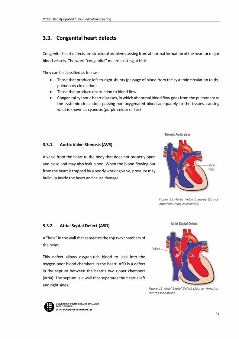
3.3.1. Aortic Valve Stenosis (AVS)
A valve from the heart to the body that does not properly open
and close and may also leak blood. When the blood flowing out
from the heart is trapped by a poorly working valve, pressure may
build up inside the heart and cause damage.
3.3.2. Atrial Septal Defect (ASD)
A "hole" in the wall that separates the top two chambers of
the heart.
This defect allows oxygen-rich blood to leak into the
oxygen-poor blood chambers in the heart. ASD is a defect
in the septum between the heart's two upper chambers
(atria). The septum is a wall that separates the heart's left
and right sides.
Figure 12 Aortic Valve Stenosis (Source: American Heart Association)
Figure 13 Atrial Septal Defect (Source: American Heart Association)

Memoria
32
3.3.3. Coarctation of the Aorta (CoA)
A narrowing of the major artery (the aorta) that carries blood to
the body.
This narrowing affects blood flow where the arteries branch out
to carry blood along separate vessels to the upper and lower
parts of the body. CoA can cause high blood pressure or heart
damage.
3.3.4. Complete Atrioventricular Canal defect
(CAVC)
A large hole in center of the heart affecting all four
chambers where they would normally be divided. When a
heart is properly divided, the oxygen-rich blood from the
lungs does not mix with the oxygen-poor blood from the
body. A CAVC allows blood to mix and the chambers and
valves to not properly route the blood to each station of
circulation.
Figure 14 Coarctation of the Aorta (Source: American Heart Association)
Figure 15 Complete Atrioventricular Canal defect (Source: American Heart Association)

Virtual Reality applied to biomedical engineering
33
3.3.5. Patent Ductus Arteriosus (PDA)
An unclosed hole in the aorta.
Before a baby is born, the fetus' blood does not need to go
to the lungs to get oxygenated. The ductus arteriosus is a
hole that allows the blood to skip the circulation to the
lungs. However, when the baby is born, the blood must
receive oxygen in the lungs and this hole is supposed to
close. If the ductus arteriosus is still open (or patent) the
blood may skip this necessary step of circulation. The open
hole is called the patent ductus arteriosus.
3.3.6. Tetralogy of Fallot (ToF)
A heart defect that features four problems.
They are:
• a hole between the lower chambers of the heart
• an obstruction from the heart to the lungs
• The aorta (blood vessel) lies over the hole in the lower chambers
• The muscle surrounding the lower right chamber becomes overly thickened
Figure 17 Tetralogy of Fallot (Source: American Heart Association)
Figure 16 Patent Ductus Arteriosus (Source: American Heart Association)

Memoria
34

Virtual Reality applied to biomedical engineering
35
4. MEDICAL IMAGES RECONSTRUCTION
The reconstruction of medical images allows transforming the images obtained with techniques of data
acquisition into numerical and geometrical format dates.
A good result of the project is based on the quality and adequacy of these medical images, from which
the 3D models of the hearts are obtained. For the project it is necessary that both the ventricles, the
atria and the blood vessels that are connected to the heart are well represented, since most of the
diseases are related to them.
Every process of reconstruction of medical images is made up of several parts:
1. - Obtaining medical images 2. - Segmentation of the images
Figure 19 Doctor looking medical images (Source: IBM)
3. - Geometric reconstruction 4. - Mesh processing
Figure 18 Heart segmentation (Source: Screenshot Mimics Medical)
Figure 20 3D reconstruction (Source: Screenshot Mimics Medical)
Figure 21 Mesh (Source: Screenshot Blender)
Memoria
36
4.1. Medical imaging
This project has been realized thanks to the medical images obtained by the Hospital Sant Joan de Déu.
For better understanding, it is necessary to know what a medical image is and the different obtaining
techniques.
Medical imaging encompasses different imaging modalities and processes to image and represent the
interior of the human body for diagnostic and treatment purposes.
Medical imaging is crucial in a variety of medical setting and at all major levels of health care. It is also
a non-invasive procedure where no instrument is introduced into a patient's body which is the case for
most imaging techniques used.
Though medical/clinical judgment may be sufficient prior to treatment of many conditions, the use of
diagnostic imaging services is paramount in confirming, correctly assessing and documenting courses
of many diseases as well as in assessing responses to treatment. Furthermore, medical imaging is
frequently justified in the follow-up of a disease already diagnosed and/or treated.
With improved health care policy and increasing availability of medical equipment, the number of
global imaging-based procedures is increasing considerably. Effective, safe, and high-quality imaging is
important for much medical decision-making and can reduce unnecessary procedures.
Each type of technology gives different information about the area of the body being studied or
treated, related to possible disease, injury, or the effectiveness of medical treatment. Therefore, both
the quality and the content of the image is largely influenced by the technique used to obtain it.
4.1.1. Conventional radiography
Radiography is the use of x-rays to visualize the internal structures of a patient. X-Rays are a form of
electromagnetic radiation, produced by an x-ray tube. The x-rays are passed through the body and
captured behind the patient by a detector. There is variance in absorption of the x-rays by different
tissues within the body, dense bone absorbs more radiation, while soft tissue allows more to pass
through. This variance produces contrast within the image to give a 2D representation of all the
structures within the patient.

Virtual Reality applied to biomedical engineering
37
4.1.2. Computed tomography (CT)
Also known as Computed axial tomography (CAT) is an imaging modality that utilizes x-ray photons for
image production, with digital reconstruction. An x-ray tube produces an x-ray beam that passes
through the patient. This beam is captured by the detectors and reconstructed to create a two or three
dimensional image.
The data captured by the scanner is digitally converted by various algorithms into reconstructed
images, which represent a cross-sectional slice through the patient at that level. Each image is acquired
at a slightly different angle and results from a different reconstruction algorithm. The individual volume
elements that make up the image are each displayed as a two-dimensional pixel, each of which carries
a designation of density or attenuation.
Figure 22 Computed Tomography (Source: LifeBridge Health)
4.1.3. Magnetic resonance imaging (MRI)
Magnetic resonance imaging (MRI), is a medical imaging technique used in radiology to visualize
detailed internal structures using magnetic radiation. MRI provides real-time, three-dimensional views
of body organs with good soft tissue contrast, making visualization of brain, spine, muscles, joints and
other structures excellent. It is multiplanar, which means that images can be obtained in multiple body
planes without changing positions.

Memoria
38
4.1.4. 3D angiography
Angiography is a diagnostic imaging test whose function is the study of blood vessels that are not visible
by conventional radiology. The process is based on intravenous injection of a contrast media into the
blood vessels for the study. X-rays cannot pass through the compound, so the morphology of the
arterial tree is revealed on the radiographic plate.
Angiography can be divided into two phases: the first consists in introducing the contrast, and the
second phase is to use one of the three previous diagnostic technique to obtain an image.
It is commonly used to assess the coronary arteries of the heart.
4.1.5. Echocardiogram
An echocardiogram is an image obtained by applying ultrasound to the interior of the heart. To perform
this technique, it is necessary to place electrodes on the patient's chest. The doctor passes the probe
through the chest area to record the images. The time it takes to perform the echocardiogram is
between 40 and 60 minutes. Echocardiograms can detect any cardiac defect and malfunction in the
muscle.

Virtual Reality applied to biomedical engineering
39
4.2. Medical image file formats
Image file formats provide a standardized way to store the information describing an image in a
computer file.
A medical image data set consists typically of:
• One or more images representing the projection of an anatomical volume onto an image plane
(projection or planar imaging)
• A series of images representing thin slices through a volume (tomographic or multislice two-
dimensional imaging)
• A set of data from a volume (volume or three-dimensional imaging)
• A multiple acquisition of the same tomographic or volume image over time to produce a
dynamic series of acquisitions (four-dimensional imaging)
The file format describes how the image data are organized inside the image file and how the pixel
data should be interpreted by a software for the correct loading and visualization.
Medical image file formats can be divided in two categories. The first is formats intended to standardize
the images generated by diagnostic modalities, e.g., Dicom. The second is formats born with the aim
to facilitate and strengthen post-processing analysis, e.g., Analyze, Nifti, and Minc.
In this project, the firsts ones are going to be used. Digital Imaging and Communications in Medicine
(DICOM) is a standard for storing and transmitting medical images. DICOM has been central to the
development of modern radiological imaging and incorporates standards for imaging modalities such
as radiography, ultrasonography, computed tomography (CT), magnetic resonance imaging (MRI), and
radiation therapy.

Memoria
40
4.3. Image segmentation
Segmentation is the partition of a digital image in multiple regions according to a given criterion.
The methods to carry out the segmentation process vary widely depending on the specific need for
visualization, type of image, and other factors. For example, the segmentation of heart tissue has
different requirements than that of other organs of the human body.
It has been found that specialized methods for particular applications of segmentation can get better
results than general methods.
The purpose of segmentation is to locate objects and regions of interest (ROI).
Unfortunately, many of the existing segmentation algorithms are still too simple to get accurate results,
so this part has to be done manually or semi-automatically.
4.3.1. Thresholding
The simplest method of image segmentation is called the thresholding method. This method is based
on a clip-level (or a threshold value) to turn a gray-scale image into a binary image.
The key is to select the threshold value (or values when multiple-levels are selected) from the
radiographs and DICOM images.
A threshold can be applied to segment the object and background. Mathematically the threshold can
be defined as follows:
𝑟𝑖, 𝑗 = {1 𝑝𝑖, 𝑗 ≥ 𝑇
0 𝑝𝑖, 𝑗 < 𝑇
Where ri, j is the resulting pixel at co-ordinate (i, j), pi, j is the pixel of input image and T is the value of
threshold.

Virtual Reality applied to biomedical engineering
41
4.3.2. Region based segmentation (Region Growing)
Region based methods are based on the principle of homogeneity - pixels with similar properties are
clustered together to form a homogenous region. The criteria for homogeneity is most of the time gray
level of pixels and this criterion can be specified by following conditions:
𝑅1 ∪ 𝑅2 ∪ 𝑅3 ∪ … ∪ 𝑅𝑖 = 𝐼
where R1, R2, R3, …Ri are the region in the image I, and further:
𝑅1 ∩ 𝑅2 ∩ 𝑅3 ∩ … ∩ 𝑅𝑖 = 0
This is as per the set theory of homogeneity.
Region based segmentation is further divided into three types based on the principle of region growing:
• Region merging
• Region splitting
• Split and merge
4.3.2.1. Region merging
In this method some seeding points are required to initialize the process, the segmentation results are
dependent on the choice of seeds.
Regions are grown iteratively by merging the neighboring pixels depending upon the merging criterion.
This process is continued until all pixels are assigned to their respective regions as per merging
criterion.
4.3.2.2. Region splitting
Its principle is just opposite to region merging and whole image is continuously split until no further
splitting of a region is possible.
4.3.2.3. Split and merge method
This is the combination of splits and merges utilizing the advantage of the two methods. This method
is based on quad quadrant tree representation of data where by image segment is split into four
quadrants provided the original segment is non-uniform in properties. After this the four neighboring
squares are merged depending on the uniformity of the region (segments). This split and merge
process is continued until no further split and merge is possible.
Memoria
42
4.4. Geometric reconstruction & volume rendering
The term volume rendering comprises a set of techniques for rendering discrete 3D data sets. With
respect to medical imaging, such data is acquired from the different sources explained in section 5.1.
Each 2-dimensional subset had to be visualized and interpreted separately. Although visualizing a
volumetric data set as 3-dimensional entities is not an easy task, it is both worthwhile and rewarding.
To summarize succinctly, volume rendering is a very powerful way for visualizing such 3-dimensional
scalar fields. It also helps in the interpretation of the contained data values.
The 3D reconstruction of tissues is performed with digital processing techniques. A 3D medical image
in grey scale is represented by a matrix of dimensions mxnxz, formed by the parallel stacking of z cuts
of the same resolution, with size mxn pixels, where each element of the matrix is a grey intensity value
obtained by the interaction of radiation in the tissue. To maintain the ratio of the size of the
reconstructed volume to the actual size of the tissue, the spacing of each voxel that makes up the
volume is taken into account, which is obtained from the information included in the medical image
after the segmentation.
It has been chosen using numerical methods that approximate a solution to real problems and allow
obtaining anatomical models of tissues. However, this approach is affected by the complexity of the
anatomical structures of hard and soft tissues, generally asymmetric, in whose analysis it is difficult to
perform simplifications due to errors in the resolution of the differential equations of the problem,
caused by complex geometries, inadequate imposition of boundary conditions and external loads.
Reconstructions of triangular meshes are the most commonly used and the easiest to treat in polygonal
couplings.
In addition, a quad mesh can always be obtained using mesh generation techniques. This is done
through software, which takes into account several factors for generation:
• The surfaces have to be consistent and topologically correct.
• Proper form of the mesh.
• Smoothing the mesh: use smoothing techniques.
• Quality

Virtual Reality applied to biomedical engineering
43
4.5. Mesh processing
It consists of converting the geometry of the initial mesh into the mesh format that is desired
according to the requirements of the problem.
A processing of the mesh, is to change the geometry of the mesh from triangular to square with
transformation methods, for example. It is also considered a processing of the mesh to apply
smoothing techniques or other techniques that suppose an improvement in the quality of the
model according to the requirements of the project.

Memoria
44

Virtual Reality applied to biomedical engineering
45
5. PROJECT PLANNING
5.1. Methodology
This project is done by two people, therefore besides just developing the project, there have to be a
communication process, consensus and an exchange of information between the two members so that
all the tasks are carried out in a fluid and efficient way.
Analysis & proposals
Election & execution
Follow-up
Necessity
That is why a methodology with the following steps is followed:
• Necessity: The medical necessity from which to design the right solution must be identified. In
the case of this project, the need is demanded by the doctors of the Hospital Sant Joan de Déu.
They are the ones who say what is need to improve.
• Analysis & proposals: Once the problem is detected, it is proceeded to study it and look for the
current solutions to the problem. Both members of the team must think and raise proposals
for each problem.

Memoria
46
• Election & execution: Once all the alternatives are presented, it has to be chosen the one that
seems more efficient, feasible or appropriate to the initial requirements.
Next, it is proceeded to the development of each solution proposed according to the
requirements established by the doctors.
• Follow-up: Once the task is completed, the process of verification and efficiency of the doctors
begins. In case there were problems or functions that do not work in the desired way, the
process to solve the problem needs to begin again.
5.2. Planning
The planning used to develop the project consisted of performing two tasks simultaneously: the 3D
modelling of the hearts and the design of the application.
For the 3D modelling part, it was essential to maintain contact with the Hospital Sant Joan de Déu,
being they who provided the DICOM images to segment and validated after the modelling process that
was applied to them. The images of the hospital corresponded to medical images obtained from
angiographies and resonances made to patients that were exported in .dcm format.
From here, the first step of the project consisted in the segmentation, cleaning and smoothing of the
3D model (through Mimics / Osirix and Blender).
At the same time that we worked in the modelling of hearts, the design of the application started. This
was done using the Unity 3D software. First, a main menu and scene was created. Then, several buttons
to interact with the imported heart.
The next step was to optimize the imported segmented and validated hearts in the application, through
a very simple process that can be done without programming knowledge and makes planning easier
for doctors.
Once the hearts were introduced, the interactions were added: scaling, rotation, the option to move
around the environment and to visualize different imported hearts. Finally, the project concluded with
the validation of it by the students, tutors, the people responsible of VISYON and the doctors of the
hospital.

Virtual Reality applied to biomedical engineering
47
5.2.1. Gantt Chart
In order to guarantee the realization of the project in the specified time, a Gantt diagram has been
performed to temporarily schedule the different tasks and documents to be drafted.
There are also meetings every two weeks between UPC - VISYON and UPC - Hospital Sant Joan de Déu.


Virtual Reality applied to biomedical engineering
49
GANNT CHART

Memoria
50

Virtual Reality applied to biomedical engineering
51
6. SEGMENTATION PREPARATION
The only thing left to start is to choose the program that we will use to perform the segmentation.
6.1. Analysis and Selection of the segmentation program
In order to realize the 3D modelling process of the hearts, a previous study has been done of the
different 3D design software existing in the market. Having no prior knowledge on this field, we
dedicated some months to reading and investigating which were the most complete and used.
Thereby, some software were rejected until selecting the best two: Materialise Mimics Innovation and
OsiriX, both combined with Blender.
Some characteristics were defined and a deeper study of these software was made considering the
following factors of interest:
• Importation formats of the files that the program supports: The medical image file can be
saved in different formats and with different characteristics each. The format explains how
the information of the image is organised and saved, and how it should be interpreted by the
program which will open and visualise it. The format DICOM, previously explained in section
4.2, is nowadays the most used. Neither Mimics nor OsiriX had a problem opening the files
DICOM that doctors from Hospital Sant Joan de Déu provided.
• The segmentation tools that has:
o Manual segmentation: Manual segmentation with OsiriX is a little bit basic, since it
only allows drawing with a paint brush the interesting parts. On the other hand,
Mimics presents a largest quantity of manual tools that allow to obtain more
accurate and faster results. It is a semi-automatic segmentation, on the sense that
concrete slices can be manually segmented and results can be automatically spread
to the whole series. In this sense, the one that presents more resources and,
therefore, seems more efficient, would be Mimics.
o Automatic segmentation: Automatic segmentation is similar in both cases, but
seems to be more accurate in OsiriX. Nevertheless, the precision in the cardiac organ
is not the adequate in neither of the programs, since the segmentation is not
correctly made due to not isolating the ribs and not separating the different parts.

Memoria
52
• The operative system of the device: for OsiriX the only version available is in MacOS and for
Mimics in Windows.
• The quality and efficiency of the results.
• The exportation formats of the models: The formats that the program Unity accepts to
import the 3D models are .fbx and .obj; therefore, since the two selected programs do not
allow to export it directly to these formats, it would be need to complement it with Blender
to convert the formats and put the final touches to the models.
• Loading time of the program: since the files are pretty heavy, it interests for the loading time
to be fast. Both programs require computers with a good hardware.
• Interface of the user: it is wanted to be easy to understand, simple to use and fast. Although
MacOS is known for being more intuitive, in our case it seemed to us that it was much more
easy to understand and use Mimics than OsiriX.
• Tutorials, documents and available aids on the Internet: being beginners, it is of great
interest the amount of documents and help tutorials on the Internet. Both Mimics and OsiriX
offered a wide range of documents, highlighting that Materialise Mimics Innovation,
Materialise company, provides its own tutorials on the Internet.
Since the potential of these programs was seen, it was decided to do the segmentation process with
both of them, and thus see and compare the obtained results.

Virtual Reality applied to biomedical engineering
53
6.2. 3D Models & Design requirements
Once chosen the software and before beginning the project’s implementation, some common
characteristics for the 3D models of the hearts were defined.
During the 3D modelling process, it was considered that all heart models should obey the following
design characteristics:
• To obtain the most accurate model possible.
o All elements not related with the heart should be deleted, just like bones o muscles
around.
o It is necessary to locate the congenital heart defects area before beginning deleting
to not erase the pertinent part, and taking into account the length of the arteries or
veins, depending on whether the congenital heart defects were located in a vein or
artery far from the heart.
• To obtain a 3D model of good quality.
o It was needed to obtain a 3D model that coincided with a real heart.
o The faces of the 3D model needed to be the most aesthetic possible, that is why
smoothing methods were applied.
• To differentiate the different parts of the heart. It was used to do so a colour palette based
on those used in cardiology.
o The oxygenated part of the heart: colours red. It contains the aorta artery, the
pulmonary veins, the atrium and the left ventricle.
o The deoxygenated part of the heart: colours blue. It contains the vena cava, the
pulmonary arteries, the atrium and the right ventricle.
o The area of the pathology: colour yellow.

Memoria
54

Virtual Reality applied to biomedical engineering
55
7. SEGMENTATION PROCESS
The whole process of treatment of medical images explained in section 4. Medical images
reconstruction, will be applied in our real case below to understand the theory and look at the results
obtained in the practice.
It will be described the required post-processing part from the moment that the medical images are
acquired until the 3D reconstructions in OBJ format are obtained.
The first step for the image reconstruction, already explained, is to acquire the medical images of the
patient in one of the tests described in section 4.1. Medical Imaging. Each typology of the image will
contribute with a different information and the doctor will be the responsible to determine which is
the adequate for each diagnosis.
The files will have a DICOM format (with .dcm extension)
From now on and through the programs Mimics and OsiriX, the medical images from the files will be
imported to begin with the segmentation. This process will be explained right after for each one of the
programs.
7.1. OsiriX
Let’s begin with Osirix:
Navigate to the folder that contains your DICOM data set. Click the Open button.
OsiriX will ask you if you want to copy the DICOM files into the OsiriX database, or only copy the links
to these files. Click "Copy Files."
OsiriX will begin to copy the files into the database. A progress bar will be shown on the lower left-
hand corner. When the data is imported you'll see a small orange circle with a "+" in it. This orange
circle will eventually go away when OsiriX is finished analysing the study, but you can open the study
and work with it while OsiriX does some clean-up postprocessing.
Once the project is opened you can set the contrast value you prefer, to see the images clearer.

Memoria
56
Then to start the segmentation, it is used Grow Region 2D/3D Segmentation under ROI menu.
Figure 23 OsiriX Segmentation step (Source: Screenshot OsiriX)
In the Segmentation Parameters window that pops up, set the threshold value desirable and then
select a starting point for the algorithm. Left click on the heart. Green crosshairs will show. All of the
heart parts that are contiguous with point you clicked will now be highlighted in green.
Figure 24 OsiriX Segmentation step (Source: Screenshot OsiriX)

Virtual Reality applied to biomedical engineering
57
Click the Compute button and Osirix will propagate the threshold.
Figure 25 OsiriX Segmentation step (Source: Screenshot OsiriX)
Trying to generate a 3D surface model directly from the 3D Surface Rendering function underneath the
3D Viewer menu is tempting to use, however it will not work well for generating STL files.
Pixel values can be modified to have a better visualization of the segmentation. Inside ROIs to 3024
and Outside ROIs to -3024, obtaining this result:
Figure 26 OsiriX Segmentation step (Source: Screenshot OsiriX)
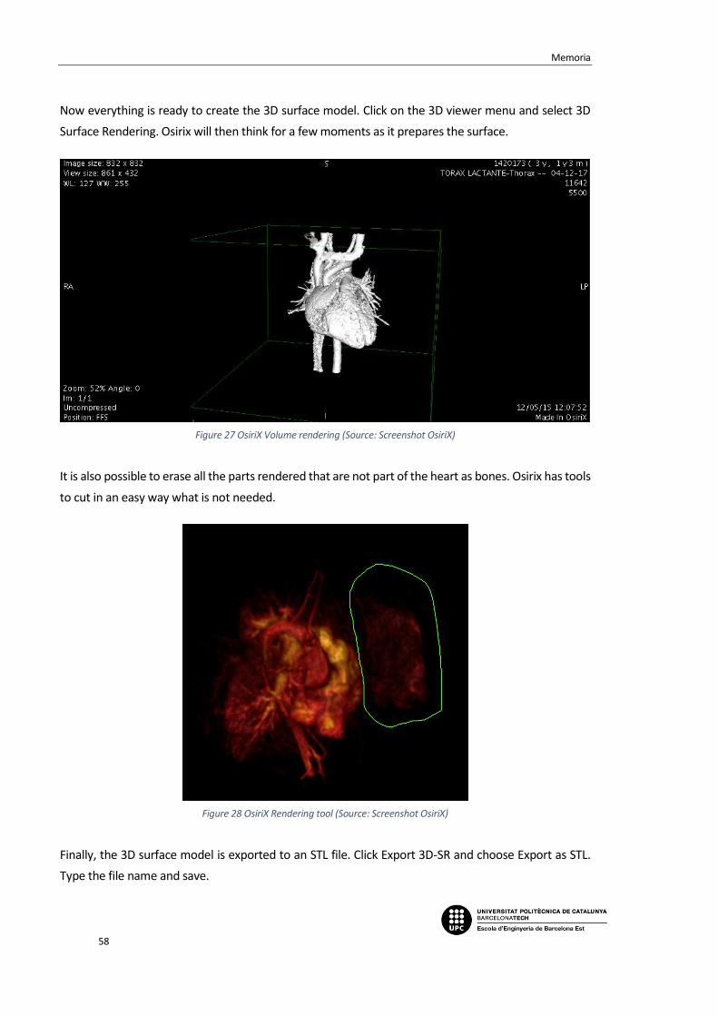
Memoria
58
Now everything is ready to create the 3D surface model. Click on the 3D viewer menu and select 3D
Surface Rendering. Osirix will then think for a few moments as it prepares the surface.
Figure 27 OsiriX Volume rendering (Source: Screenshot OsiriX)
It is also possible to erase all the parts rendered that are not part of the heart as bones. Osirix has tools
to cut in an easy way what is not needed.
Figure 28 OsiriX Rendering tool (Source: Screenshot OsiriX)
Finally, the 3D surface model is exported to an STL file. Click Export 3D-SR and choose Export as STL.
Type the file name and save.

Virtual Reality applied to biomedical engineering
59
7.2. Mimics Medical
With Mimics the steps are a bit different and the results more complete and accurate. The abundance
of specialized tools in Mimics made the segmentation process as well as 3D editing and refining phases
effortless.
Once the DICOM file is imported and a new project started, the first thing to adjust is the contrast and
the volume rendering to the values that fits better depending the DICOM images. Volume rendering
allows you to quickly visualize your 2D data as a 3D object without having to take the time to segment
and create a model. It is only a visualization tool, but gives a nice impression of what your model will
look like.
Then, a specific module for Heart Segmentation can be used by clicking Segment Cardiovascular
CT Heart, and a Threshold Range has to be chosen after restricting the Bouding Box (in red) to
approximate the heart dimensions.
Thresholding classifies all pixels within a certain Hounsfield range as the same colour, or mask. There
are predefined settings for certain biological materials available in the thresholding toolbar. A lower
threshold allows segmentation of soft tissue, whereas a higher threshold segments bone. An
equilibrium between both has to be found to get a good rendering.
Figure 29 Mimics Segmentation step (Source: Screenshot Mimics)
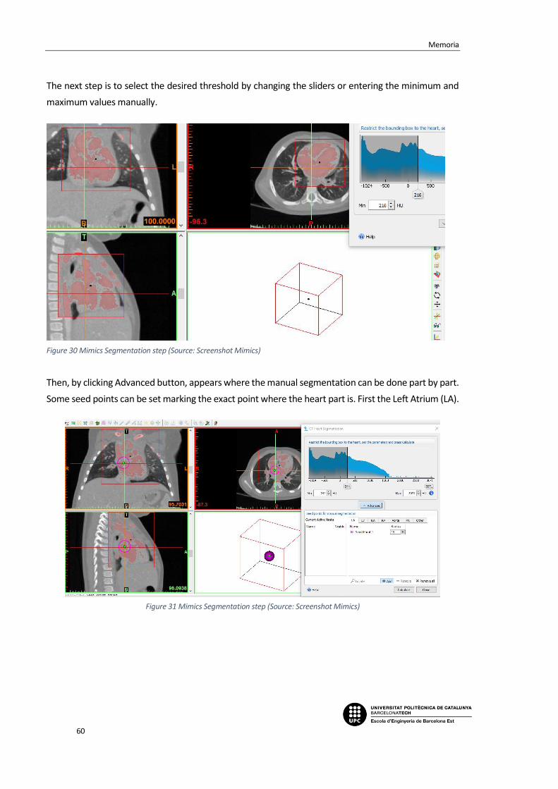
Memoria
60
The next step is to select the desired threshold by changing the sliders or entering the minimum and
maximum values manually.
Figure 30 Mimics Segmentation step (Source: Screenshot Mimics)
Then, by clicking Advanced button, appears where the manual segmentation can be done part by part.
Some seed points can be set marking the exact point where the heart part is. First the Left Atrium (LA).
Figure 31 Mimics Segmentation step (Source: Screenshot Mimics)

Virtual Reality applied to biomedical engineering
61
Followed by Left Ventricle (LV).
Figure 32 Mimics Segmentation step (Source: Screenshot Mimics)
The radius of the seeds can be modified for smaller parts as the Right Atrium (RA).
Figure 33 Mimics Segmentation step (Source: Screenshot Mimics)

Memoria
62
And the last heart chamber, the Right Ventricle (RV).
Figure 34 Mimics Segmentation step (Source: Screenshot Mimics)
For the Aorta segmentation multiple seed points were used, following the ascending and descending
Aorta and the same for the Pulmonary Artery (PA).
Figure 35 Mimics Segmentation step (Source: Screenshot Mimics)

Virtual Reality applied to biomedical engineering
63
Figure 36 Mimics Segmentation step (Source: Screenshot Mimics)
Finally, in Other section, the pathology can be segmented in yellow. In this case was a Coarctation of
the Aorta (CoA).
Figure 37 Mimics Segmentation step (Source: Screenshot Mimics)

Memoria
64
By clicking Calculate, Mimics will start calculating the different masks per part.
Figure 38 Mimics Segmentation step (Source: Screenshot Mimics)
The masks per each part are created and can be checked, modified and hided.
Figure 39 Mimics Segmentation (Source: Screenshot Mimics)

Virtual Reality applied to biomedical engineering
65
The results are displayed showing the 3D heart segmented.
Figure 41 Mimics Segmentation Result (Source: Screenshot Mimics)
This heart model obtained can be modified with some tools before exporting it to have better quality
and a more accurate 3D object.
Figure 40 Mimics Segmentation result with and without pathology (Source: Screenshot Mimics)

Memoria
66
Region Growing and Dynamic Region Growing
Region growing is used to separate masks into different parts as well as to get rid of floating pixels.
Remember that thresholding must be done prior to region growing. The Green Mask contains the
deleted parts and the yellow one is the new one generated. As seen it is not totally accurate.
Figure 42 Mimics Segmentation Tool (Source: Screenshot Mimics)
Dynamic Region Grow allows you to grow a mask from a selected point without having to threshold
first. It is extremely useful for vessels, nerves, and arteries.
Figure 43 Mimics Segmentation Tool (Source: Screenshot Mimics)

Virtual Reality applied to biomedical engineering
67
Edit Masks
The area contained within a mask can be modified using the edit mask tools, and erase the leftover
parts.
Multiple Slice Edit
Multiple Slice Edit is a timesaving tool because it allows you to apply the manual editing done on one
slice to other slices. Select adds pixels to a slice and deselect removes pixels. You can control the size
and shape of your editing tool by changing type, width, or height.
Figure 45 Mimics Segmentation Tool (Source: Screenshot Mimics)
Figure 44 Mimics Segmentation Tool (Source: Screenshot Mimics)

Memoria
68
Morphology Operations
Morphology operations take or add pixels to the source mask. You can use a morphology operation as
an alternative to multiple slice edit.
Figure 46 Mimics Segmentation Tool (Source: Screenshot Mimics)
Erode takes away the number of pixels selected and dilate adds the number of pixels to the boundary
of the mask.
Figure 47 Morphology Operations (Source: Mimics Medical Guide)
Split Mask
The Split Mask tool is part of the Segment menu and allows splitting of a single mask into two separate
masks. To open the tool go to Segment > Split Mask in the menu. This tool allows easy and quick
separation of anatomical parts e.g. heart from the surrounding rib cage or separating talus and
calcaneus in the foot.
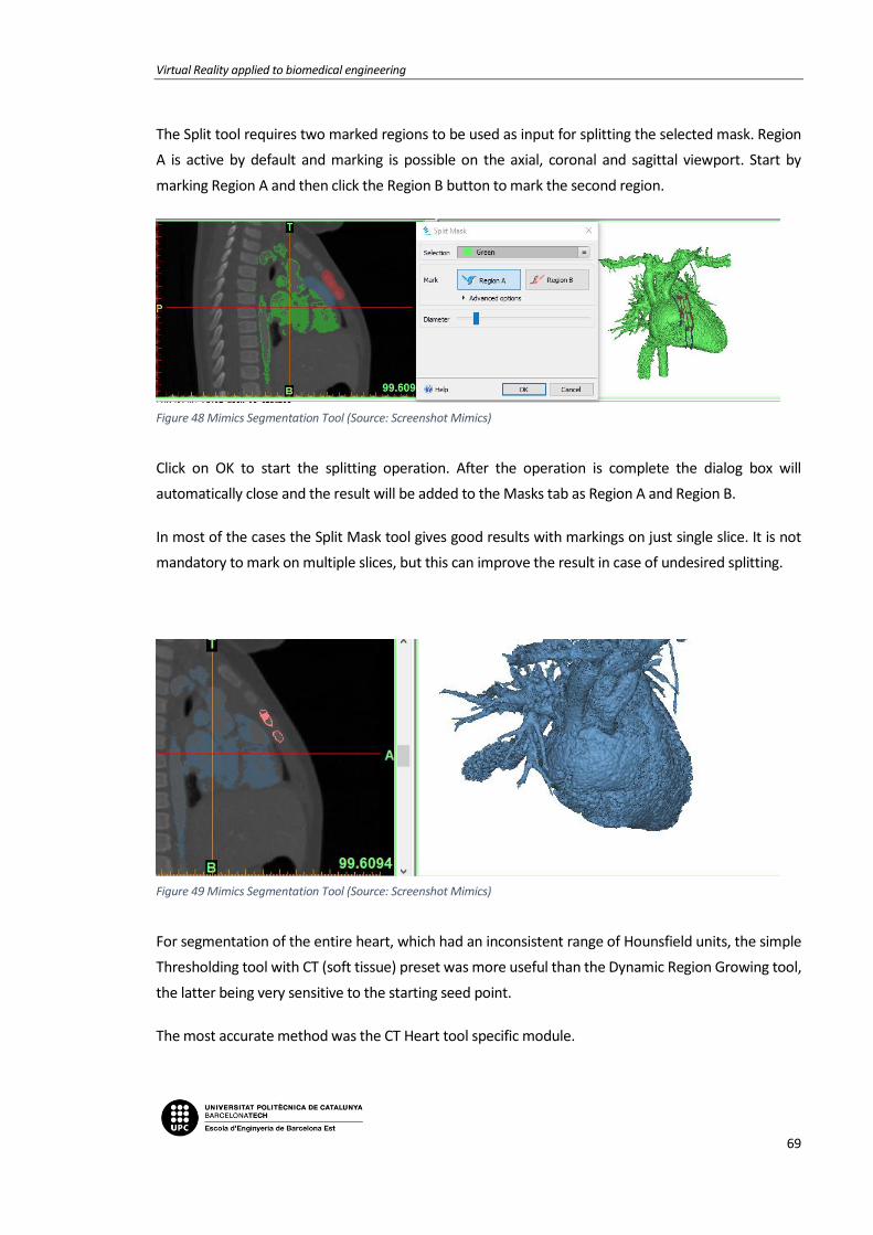
Virtual Reality applied to biomedical engineering
69
The Split tool requires two marked regions to be used as input for splitting the selected mask. Region
A is active by default and marking is possible on the axial, coronal and sagittal viewport. Start by
marking Region A and then click the Region B button to mark the second region.
Figure 48 Mimics Segmentation Tool (Source: Screenshot Mimics)
Click on OK to start the splitting operation. After the operation is complete the dialog box will
automatically close and the result will be added to the Masks tab as Region A and Region B.
In most of the cases the Split Mask tool gives good results with markings on just single slice. It is not
mandatory to mark on multiple slices, but this can improve the result in case of undesired splitting.
Figure 49 Mimics Segmentation Tool (Source: Screenshot Mimics)
For segmentation of the entire heart, which had an inconsistent range of Hounsfield units, the simple
Thresholding tool with CT (soft tissue) preset was more useful than the Dynamic Region Growing tool,
the latter being very sensitive to the starting seed point.
The most accurate method was the CT Heart tool specific module.

Memoria
70
Doctors have all necessary knowledge to carry out efficiently the segmentation and creation of a 3D
model and every informatic tool is provided to them. As doctors and surgeons comprehend at first
sight what needs to be analysed in tomographies, resonances, etc., they can easily select the interested
regions (ROI) which are basic to create the 3D reconstruction.
The last step is to export the .stl file. If wanted, Mimics gives the possibility to smooth and to reduce
the mesh. To obtain the best quality, a Custom configuration has to be chosen.
For the smoothing: the more iterations and smooth factor, the more quality.
For the triangle reduction: the less tolerance and edge angle, the more quality.
Figure 50 Mimics Export parameters (Source: Screenshot Mimics)
If not, it can be done by Blender as explained in the following section.

Virtual Reality applied to biomedical engineering
71
7.3. Blender
The last step for both ways is to use Blender to smooth and convert the 3D .stl files to .obj since is the
format that Unity admits.
You can see from the 3D rendering that there are many small islands of material that have been
included with the STL file. Also, the heart has a very pixelated appearance. It does not have the smooth
surface that would be expected on a real heart. These problems are fixed by doing a little
postprocessing.
Once Blender is opened, import the STL file. From the File menu select Import, STL, and double-click it.
Blender will think for a few seconds and then return to what appears to be an empty scene. To find the
heart, use the mouse scroll wheel to zoom out. When the heart is found, it seems to be gigantic. In
Blender, an arbitrary unit of measurement called a "blender unit" is used. When the heart is imported,
1 mm of real size was translated into 1 blender unit. Thus, the heart appears to be hundreds of blender
units large, and appears very big.
The 3D model is also offset from the origin. To fix that, select the heart, and in the lower left corner of
the window click on the Object menu. Select Transform, Geometry to Origin and the heart is now
centered on the middle of the scene.
Figure 51 Blender smoothing step (Source: Screenshot Blender)

Memoria
72
First, let's get rid of the extra mesh islands. There is a menu in the lower left-hand corner of the window
that says Object Mode. Click on this and go to Edit Mode. In this mode it can be edit individual edges
and vertices of the model. Right now, the entire model is selected because everything is orange. In edit
mode you can select vertices, edges, or faces.
Right click on a single vertex on the model and under the Select menu, click Linked. This selects every
vertex that is connected to the initial vertex selected. The selection has to be invert, by again clicking
on the Select menu and choosing Inverse.
Figure 52 Blender smoothing step (Source: Screenshot Blender)
Now all of those unwanted mesh islands are selected and they only have to be deleted.
Then, to get rid of the pixelated appearance of the model surface, all the polygons have to be converted
to triangles. The smoothing algorithms just work better with triangles. Once the model is all selected it
has to be clicked Mesh menu, Faces, Triangulate Faces. This will convert any remaining complex
polygons to triangles.
Figure 53 Blender smoothing step (Source: Screenshot Blender)

Virtual Reality applied to biomedical engineering
73
Go back to Object mode by hitting the tab button or selecting Object Mode from the bottom toolbar.
A smoothing function is going to be applied, called a modifier. Along the right of the screen you'll see
a series of icons, one of which is a wrench. Click on that. This brings up the modifier panel, a series of
tools that Blender uses to manipulate digital objects. Click on the Add Modifier button and select the
Smooth modifier. Leaving the Factor value at 0.5, the Repeat factor can be increased until the surface
appearance of the model is the desirable. Click on the Apply button and the smoothing function has
been applied to the model.
Figure 54 Blender smoothing step (Source: Screenshot Blender)
The last step is to export the model to .obj, and everything would be ready to import the 3D heart to
de VR app done in Unity 3D.
Now, it can be seen that this is a task which requires a lot of dedication, concentration, experience and
time.
As it has been previously explained in other points of this report, the aim of this project is to create a
virtual reality app for surgical planning. Its usage will change for every new patient; therefore, it has
been considered not to add any previous model and import them from the outside.

Memoria
74

Virtual Reality applied to biomedical engineering
75
8. VIRTUAL REALITY APPLICATION
8.1. Game engine
As mentioned before, the main objective of the project was to make an optimal and easy-to-use
application. When looking for engines to carry through the project, Unity has been the best one in
terms of functionality and optimization. Even though It is true that there were many other possibilities,
it was important to note the limitations of the project, such as the experience acquired as students in
this kind of workspace and the possibility to use a paid engine or a free one.
The table of aspects from Unity gave us a free to use engine with a highly worked and intuitive
interface, which made the first steps of learning way more easy and free-flowing. Although it is possible
to get a pro version of the program, the planning of the project did not change much if it was
considered to upgrade the license.
Since Unity is constantly changing the version to bring it up to date, it was also important to pick one
and work with it within the whole project. Any changes made between versions involve a huge number
of warnings or errors in the scripting part of the project, which are something to avoid when trying to
bring a huge application to an end. Still there was not much change between the last version and the
safest one, so we chose to use the Unity 5.6.
Speaking of scripts, using Unity there was the possibility of using two programming languages: C# and
JavaScript. Both of them are highly used in most of the projects that take part in this generation, but
they mainly have different aims of work. Since Java is the most used language when developing web
projects or online platforms, C# is more object-oriented and has more general tools, what gave the
ability to search more different ways to program actions inside the application.
The objective of the project required the best possible graphic definition for the images used in the
space. Obtaining a high quality and texture 3D model for the application is for sure the most important
Figure 55 Unity Engine Logo (Source: unity3d.com)

Memoria
76
part of any project dedicated to surgery planning. The main problems that appear when trying to
transfer these models to any display engine are related to the quality of these represented objects.
Although it is something that still needs a lot of improvement from the start, when taking the image
from the patient, the other part cannot stay behind. So, it was found that there was the opportunity
to import a kind of 3D objects that were compatible with Unity and gave a really high definition when
placed in scene.
Transferring this to the virtual reality world, the engine used in the project has some of the best
performances offered in the actual market. It has been mainly used in smartphone applications
achieving very nice outcomes, but the historical implementation of this immersive game style is now a
very thankful feature between users that are getting interested in virtual reality.
There’s also something to keep in mind, and it is that the Unity community has build kind of a big forum
full of answered questions where people dedicates a lot of time and effort to participate. This ensures
a place to resolve any problems or troubles that may appear during the project, what makes It more
attainable.
The support obtained from VISYON has to be mentioned here, since although the forum has been
mentioned, that was one of the main reasons to follow this path. Their experience and work are highly
focused in the Unity engine and so there was the possibility to contribute with new ideas that might
have seemed out of the way but with some retouches have become a true innovation and source of
possibilities.
8.2. Development of the application
Before getting into the real work, it was necessary to try and decide which features had to be
implemented in the project. Since there was no previous experience from the engine, all the
possibilities were new and there was no influence at first to incline towards one option or another.
The main objective of this application when presented was to be something really easy to use for any
user, considering that not all the players could have tried this kind of technology before, and also
optimal. To achieve this, a list of features and characteristics was made and then trimmed to have only
the interactions that were important and really useful for the application. There are some features that
need really important improvements before they can become something useful in medical
applications, so implementing those making the game harder and increasing its technical requirements
was not desired.
With the first idea of the project, the application itself can be divided in some parts or categories,
depending on its role in the whole work.

Virtual Reality applied to biomedical engineering
77
8.2.1. Scene
The scene of the application is the place where everything takes place. The project is made with a
virtual reality engine so the idea was to immerse the user in a supposed hospital, where he/she could
see the 3D heart model in a familiar space.
A surgery room has been set up with some of the elements that could be found inside, all using 3D
models to make the experience more realistic and immersive. To get a clear vision from the model it
needs to have a big free spot, where also it has to receive all the interactions and still give the best
commodity when inside the game. The colors have been changed to get a clear contrast within the
room space and the heart models and the lights are set up to show all the details in the object so no
information is lost.
To reduce possible dizziness when in game mode, the space has been made in a small scale so the user
doesn’t have to move and can observe the models from any point of the room without losing sight of
it.
8.2.2. Player
To be able to move around the scene and watch the space, it is required to add a player configuration
inside the scene. This component incorporates the variables acquired from the headset and controllers
input and transforms them into in-game actions, configurated by the interactions scripts.
The component used comes from a premade setup grabbed from the Unity asset store called SteamVR,
which is made specifically for Virtual Reality devices. This is made to shorten the configuration process
Figure 56 Panoramic scene view from the application

Memoria
78
and is really used between most of the users. The player controller is named as “Manager” in the scene
and incorporates the SteamVR plugin where all the HTC inputs are set.
When entering the game mode, the player has been placed in a corner of the room so he can watch
the whole scene from the start. Since the models loaded would be in a high position it was decided
that the user would be placed also in a high place. This could let the player observe the place by looking
straight or down, instead of up, what could be tiring and lately evolve into neck pain after playing for a
long period of time.
8.2.2.1. Controls
Even though the inputs are set in the manager, the functions in every controller have been configured
by using custom scripts made for the project. There’s a clear separation between one and the other:
the left controller is set by the “ControllerFunctions” script and the right controller has the interactions
made for the game.
Inside the “ControllerFunctions” code it is found the functions for the selection of the different options
as well as the functions that each one of the selectables call when pressed.
To travel through the menu options, the player uses the left controller’s touchpad. By pressing to one
side or the other in the x axis, the menu rotates to the configured position. To select an option, the
user presses the left controller’s trigger. The other buttons have no function in the game itself, apart
from the home button that brings the user to the Steam Home page.
This system simplifies the controls and makes the gameplay easier for any kind of user. Also, it is seen
in the scene which buttons are being pressed by the player at any time, so it is easy to relocate if he/she
gets lost in the controller.
The controls from the right controller are specified in each one of the interactions set for the models.
The Rotation, Scale and Movement scripts only use the input from the right controller’s touchpad,
since this makes the gameplay easier and more comfortable. There was the option to change the linear
movement to a teleport system, but the scene itself is not really big so it was decided that this was the
better option, although it might cause a little more dizziness.
The right controller’s trigger is used to close the in-screen menus, so it works as a “back” button when
using the Options and Guide functions in the menu. As in the left controller, the other buttons do not
have a in-game function apart from the Steam Home one.

Virtual Reality applied to biomedical engineering
79
If there was an upgrade to the app in the future, it could be possible to add a laser function to the
menu button, in case the user wanted to take a picture pointing at some point of the model, for
example.
The grip buttons are not really used in most the apps because they are not placed in a comfortable
way and the user has to move its hand to properly press them. Despite of this they could be used, for
example, as the rotation function instead of the touchpad.
8.2.3. Menu
The design of the controller menu has been made in order to obtain the most user-friendly results
achievable. With an arrangement of five options, the selections have been placed in a circular form
where all the options are permanently visible in each sub-menu. The idea was to have a menu that was
clear and intuitive but also that would not disturb the vision space of the scene, so it was attached to
the left controller. This let the player have the menu inside or outside the camera range without having
to turn it on or off when needed.
There is a total of 3 different menu setups available and they all have different interactions and options
specifically designed to satisfy user’s needs. The main state has 5 functions.
8.2.3.1. Import
The first option of the main menu is the import manager. The aim of the project was to make a system
that lets the user easily transform a DICOM image into a visible 3D object and watch it with the virtual
reality kit. So, the import system has been made to fasten as much as possible this process and let the
users have a quick method to plan their incoming sessions.
Figure 57 Controller's Main Menu
Memoria
80
To work this out, an easy naming system was made: the player has to save the .obj item that he wants
to see in a specified folder and change its name to a number between 0 and 3, meaning this that it is
possible to load 4 different objects in a single runtime mode. This function ins called “Resources.Load”
and is mainly for single or few object loads. For multiple imports there are other
ways to import but this is the one that has the easiest procedure.
This method lets non-professional users understand how to change the models
they want to see without the need of and extensive tutorial that could still not
ensure a proper use of the application.
In spite of these 4 possibilities, the system has been made so that only 1 of the
models can be loaded at a time and each time a new object is charged, the last one disappears from
the scene and is replaced by the selected one.
This function also selects the scale of the object to import as also its color and the position where it is
going to be loaded.
8.2.3.2. Interactions
Rolling to the second option of the menu, there is the interactions submenu option. When selecting
this option, 4 possible actions appear in the menu. As explained before, the objective was to make the
application useful and easy, so the menu selections where reduced to 4 to keep
it simple and efficient. Even though this was the first reason to place it this way,
it is important to mention that some options were also dismissed because the
quality of the models obtained could not give a real simulation of what it was
representing. A particular case of this was the option of making a section out of
the 3D model. Right now, the objects obtained from the transformation of the
DICOM images do not give a proper model from the inside parts of the volume,
so segmentation was just something that would not give useful results.
After discarding these options, the remaining ones that were selected as the most useful and important
were: rotation, scaling, movement and screen capture. With the existing limitations, these four options
could give the user a ready to use application for surgery planning or teaching methods with accurate
models.
To make the user controls even more easy, the menu control was all kept within the left controller and
the actions selected in the interactions menu are performed with the right controller. This separation
avoids confusion and lets the player focus on each action without interacting between controllers and
so making the gameplay easier.
Figure 58 Import icon
Figure 59 Interaction's icon

Virtual Reality applied to biomedical engineering
81
Rotation
The main and most important interaction with the model was the ability to rotate it and see all its faces.
This feature gives the user the option to incline the object in all the directions by using the right
controller’s touchpad.
The rotation is set so the model can be turned 360º in all angles, so the player can first rotate the object
in a determinate position and then use another action over it. The sensitivity of the touchpad lets the
rotation to be faster or slower, depending on how far from the center the user is
pressing the button.
From the scripting part, there are many rotation methods in the Unity library.
Depending on the system used, the object selected can rotate around the center
scene pivot, a created alternative pivot or the local pivot of the object created when
it is loaded. The last option was selected because it was the one that was more
accurate and easy to use, also the one that gave the best results while performing the first tests. The
name of the function used is “transform.Rotate” and is one of the most used for single scene objects,
when looking for an individual rotation of the model.
Scaling
Another implemented function to the game is the option to change the scale of the models loaded.
Simply by pressing up or down in the right controller’s touchpad the model will gradually change its
scale to a bigger or smaller one.
The space in the room allows a big increase of the model if the user wanted to focus on a particular
part of the model. This feature also has a position sensitivity but the speed in the tip of the touchpad
has been set to a low grade to avoid undesired results or harder use of the action.
As well as the rotation function, the scaling has many options depending on how
we want to change the volume of the object. It is also possible to change every axis
in a different grade, but this would only deform the model and so give a bad
impression of the model. Because of this the function used is
“transform.localScale”, which gives the most common and expected results when thinking of it as a
random user.
Figure 60 Rotation icon
Figure 61 Scale icon

Memoria
82
Movement
When making the list of interactions for the player, the movement was placed in a medium position.
As told before, the dimensions of the room and the model are not really big so it is
possible to use the application without the ability of shifting through the scene.
Despite of this, after the first tries and tests of the game is was noticed that the
sensation of immobility directs the user to try to move in real life. This can represent
a problem since the headset is connected to the computer and, even though the
cable is long, the experience could end in an accident.
After making this hypothesis it was decided that the player needed a movement
option so he/she could travel by the room and investigate or even watch the outlook from another
perspective. The function also became more important when the app was tried in a different room.
The position of the HTC sensors can change the place and first rotation of the player component so it
is required that he/she has the ability to change its place and observe the scene from a proper spot.
Just like the two first interactions, the player movement is performed with the right controller’s
touchpad simply by pressing to the direction where the user wants to go. It has to be mentioned that
this option does not let the user to rotate the headset position, so he/she has to turn around in reality
to watch to one side or another. The function used for this action is “transform.position”.
Screen Capture
The last added feature is the screen capture. This one is thought as a tool to keep some important
information to use outside the game. If the user wants to focus on a particular part of the model and,
for example, wants to share it with some of his companions or analyze it, he can take a picture of the
screen he is watching at the moment.
To take a screenshot the player has to go to the camera option and then simply
press de left controller’s trigger, just like if he/she wanted to select one of the
other actions. The screen capture will then be saved in a specific folder inside the
project and will be available to be watched and edited as any other picture.
Figure 62 Movement icon
Figure 63 Screen Capture icon

Virtual Reality applied to biomedical engineering
83
8.2.3.3. Language selection
To make the app a little more user-friendly it has been added the option to change the language of the
game. Meaning this that the guide and options menu, as well as the indicator of the option selected
can be displayed in three different languages: English, Spanish and Catalan.
When the game starts in English by default. If the user presses the language icon, it changes to Spanish.
A second press turns into Catalan and another one starts again at English.
8.2.3.4. Controls
Things had to be clear at any part of the game for the player. An instructions screen has been added to
the main menu so the user can check the manual at any time. When selecting this option, a screen
appears in front of the camera, following it, with the instructions on how to use the
controllers and what does every button.
The game itself has been made to be easy to understand but for new users it is
required that the player has a place to see how to play the application.
8.2.3.5. Game guide
Finally, to make sure that the player does know how to make the app work, it has been set a game
guide inside the game. This selectable also pops out a screen in front of the headset, but now it is
written the instructions on how to play the game.
Figure 65 Options icon
Figure 64 Controls menu

Memoria
84
The resolution obtained from the text in the corners of the headset is highly decreased as the vision
moves towards the edges. This represented a problem when trying to make a big screen for the user
to be easy to be seen, so finally the decision has been to make a short and precise
guide, with only the necessary information to help the player get started.
For first timers, it has been set that when the app is started, this screen automatically appears in the
scene and avoids confusion when playing for the first time or after a long time.
8.2.3.6. The back button
Only inside the two submenus from import and interactions it exists a back button, which turns the
user back to the main menu and lets him/her get to another option. With this feature, the other free
buttons are kept open for new possible actions.
Figure 66 Guide icon
Figure 68 Back button icon
Figure 67 Guide menu

Virtual Reality applied to biomedical engineering
85
8.3. How to use
In this section there will be a quick guide on how to use the application.
8.3.1. Preparation
To start playing, first it is needed to prepare the headset and controllers, and make sure that they are
working inside the sensors space.
Also before entering the program, the user has to pick the 3D models that will be able to load inside
the game and put them inside the “Resources” folder inside the game project.
Figure 69 Representation of object saving
To load models in-game, it is required to change its names to numbers between 0 to 4, in case the user
wants to charge many objects together.
8.3.2. Game Start
When the game starts, the “Controls” screen appears in front of the headset. This is a function
introduced for new users. In case the player has not read or heard the instructions before starting the
application, this screen will help to start using it.
To close this window, the user has to press the trigger on the right controller. It is still possible to reach
it at any time inside the game, by going to the controls cube and pressing the left controller’s trigger.
Project folder
Project folder

Memoria
86
8.3.3. Model import
The idea of the application is to interact with the loaded model, so before this happens, it is not possible
to interact with any object inside the room, but the ability to move around the space can be enabled
at any time.
So, to start interacting, the user has to press the left controller’s trigger when over the Import menu,
and then select one of the available options. After doing this, a model will be loaded in the center of
the room and it will be possible to interact with it.
For example, if model 2 was selected in this version:
Figure 70 Import menu. Each cube matches the model named with the same number
Figure 71 Import menu. Each cube matches the model named with the same number
Figure 72 Import menu. Each cube matches the model named with the same number
Figure 73 Import menu. Each cube matches the model named with the same number
Figure 74 Import menu. Each cube matches the model named with the same number
Figure 75 Import menu. Each cube matches the model named with the same number
Figure 76 Import menu. Each cube matches the model named with the same number
Figure 77 Import menu. Each cube matches the model named with the same number
Figure 86 Loaded heart in the centre of the room
Figure 87 Loaded heart in the center of the room
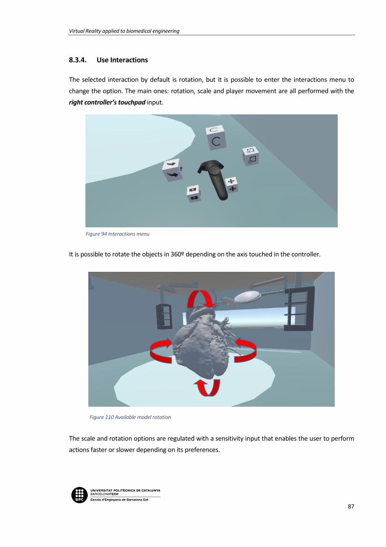
Virtual Reality applied to biomedical engineering
87
8.3.4. Use Interactions
The selected interaction by default is rotation, but it is possible to enter the interactions menu to
change the option. The main ones: rotation, scale and player movement are all performed with the
right controller’s touchpad input.
It is possible to rotate the objects in 360º depending on the axis touched in the controller.
The scale and rotation options are regulated with a sensitivity input that enables the user to perform
actions faster or slower depending on its preferences.
Figure 94 Interactions menu
Figure 95 Interactions menu
Figure 96 Interactions menu
Figure 97 Interactions menu
Figure 98 Interactions menu
Figure 99 Interactions menu
Figure 100 Interactions menu
Figure 101 Interactions menu
Figure 102 Interactions menu
Figure 103 Interactions menu
Figure 110 Available model rotation
Figure 111 Available model rotation
Figure 112 Available model rotation

Memoria
88
Finally, to provide the sensation of freedom, the user can activate the movement option. This can also
be useful to later take a picture from a better angle or just see the model from another perspective,
just like it was in real life.
Figure 118 Player vision inside the game

Virtual Reality applied to biomedical engineering
89


Virtual Reality applied to biomedical engineering
91
CONCLUTIONS
During the development of the project and now, once finished, we can confirm that the initial proposed
goals have been accomplished. Next, the conclusions which show the achievement of these goals will
be exposed:
• To create an application that gives the ability to load 3D models of hearts and interact with
them inside a virtual space.
We have accomplished the creation of a virtual reality application which allows to import 3D
models and interact with them in an attractive and intuitive way.
• To find an optimal way to make 3D models by using DICOM images from the hospital. Get high
resolution models to make the experience inside the virtual world more realistic.
It has been optimized with respect to the previous related projects, the hearts segmentation
and its reconstruction to 3D models with a new software, and a method explained in this
Bachelor Thesis which stands out for its rapidity and accuracy, the results are highly good and
they bring the sensation of immersion to the user and improve comparisons with real objects.
The hearts reconstructed still need to be cleaned and smoothed after their segmentation but
it has been possible to find a faster way than the one proposed in the beginning.
• To find an optimal system to load images to the Virtual Reality application. Making an effective
path for users to take an image and charge see and interact with it in 3D.
One of the improvements we are most proud of is to have accomplished the importing method
of the 3D models inside the application. The doctor will only need to copy the wanted object
inside a folder and it will appear directly inside the virtual reality. A simple process which does
not require programming knowledge as it had been necessary until now, and which optimizes
to the maximum the time between the reconstruction of the 3D model and the application
usage.
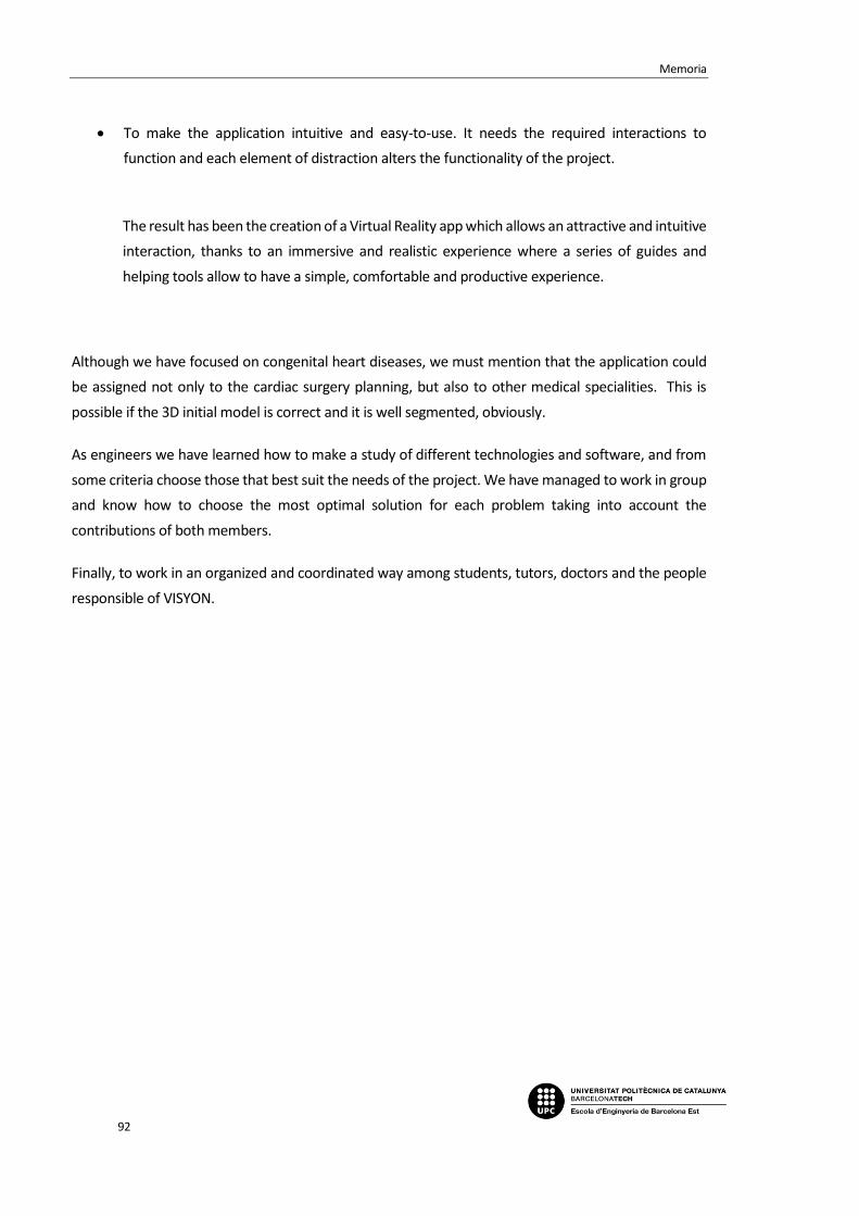
Memoria
92
• To make the application intuitive and easy-to-use. It needs the required interactions to
function and each element of distraction alters the functionality of the project.
The result has been the creation of a Virtual Reality app which allows an attractive and intuitive
interaction, thanks to an immersive and realistic experience where a series of guides and
helping tools allow to have a simple, comfortable and productive experience.
Although we have focused on congenital heart diseases, we must mention that the application could
be assigned not only to the cardiac surgery planning, but also to other medical specialities. This is
possible if the 3D initial model is correct and it is well segmented, obviously.
As engineers we have learned how to make a study of different technologies and software, and from
some criteria choose those that best suit the needs of the project. We have managed to work in group
and know how to choose the most optimal solution for each problem taking into account the
contributions of both members.
Finally, to work in an organized and coordinated way among students, tutors, doctors and the people
responsible of VISYON.

Virtual Reality applied to biomedical engineering
93


Virtual Reality applied to biomedical engineering
95
BUDGET
In this section, the costs associated with the development of the project are presented. To calculate
the budget, it has been taken into account that the project started on 09/13/2017 and ended on
01/08/2018, which corresponds to 75 days of work.
The direct costs (personnel and equipment) and indirect costs (facilities and telecommunications)
associated with the project have been calculated below:
Direct Costs
Personnel and Social Security contribution:
The calculation of the cost of personnel has been made taking into account that this project has been
carried out by two people. It has also taken into account a full-time job of 8 hours a day for 75 days
that include: Previous documentation and learning, Application architecture design, Development of
design specifications, Programming code with C # to Unity, Writing the thesis and other documents.
Which corresponds to a total of 600 hours spent by each student.
Position Nº of personnel Time (h) Cost per hour (€/h) Cost (€)
Engineers 2 600 30 36.000
TOTAL PERSONNEL COST 36.000€
For the calculation of Social Security costs, 23.6% of the contribution base was taken. According to the
salary of the staff, the cost of Social Security associated with the two workers is:
36.000€ x 0.236 = 8496€

Memoria
96
Hardware/ Software:
In this section we have taken into account the hardware and software used during the development
of the project. It has been considered that the cost associated with the computers and the HTC Vive
are fully amortized in this project, since it is not expected to be reused in other applications.
Hardware/ Software Quantity Cost per unit (€/un.) Cost (€)
Computer 1 1500 1500
HTC Vive 1 699 699
Unity3D 2 FREE 0
Blender 1 FREE 0
OsiriX / Mimics 1 728 728
TOTAL HARDWARE / SOFTWARE COST 2927€
Indirect Costs
Facilities:
The rent of an office and the expenses associated with the rent have been taken into account.
Concept Time (month) Cost per month (€/month) Cost (€)
Rent 4 300 1200
Water 4 10 40
Electricity 4 30 120
Gas 4 20 80
TOTAL FACILITIES COST 1440€
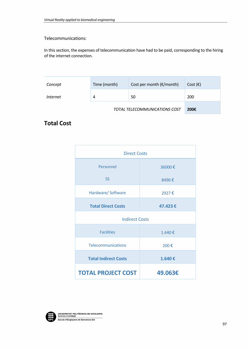
Virtual Reality applied to biomedical engineering
97
Telecommunications: In this section, the expenses of telecommunication have had to be paid, corresponding to the hiring of the internet connection.
Concept Time (month) Cost per month (€/month) Cost (€)
Internet 4 50 200
TOTAL TELECOMMUNICATIONS COST 200€
Total Cost
Direct Costs
Personnel
SS
36000 €
8496 €
Hardware/ Software 2927 €
Total Direct Costs 47.423 €
Indirect Costs
Facilities 1.440 €
Telecommunications 200 €
Total Indirect Costs 1.640 €
TOTAL PROJECT COST 49.063€

Memoria
98

Virtual Reality applied to biomedical engineering
99
9. BIBLIOGRAPHY
[1][2][3][4][5][6][7][8][9][10][11][12][6][7][13][1][14][15][16][5][17][8][18][14][19][20][19][21][22][9][1][4][23][24][25][26]
[1] X. Zhuang and J. Shen, “Multi-scale patch and multi-modality atlases for whole heart segmentation of MRI,” Med. Image Anal., vol. 31, pp. 77–87, Jul. 2016.
[2] H. Gray, “Gray, Henry. 1918. Anatomy of the Human Body.” [Online]. Available: http://www.bartleby.com/107/. [Accessed: 15-Nov-2017].
[3] NIH, “How the Heart Works | National Heart, Lung, and Blood Institute.” [Online]. Available: https://www.nhlbi.nih.gov/health-topics/how-heart-works. [Accessed: 16-Dec-2017].
[4] Wondershare, “A brief history of virtual reality.” [Online]. Available: https://filmora.wondershare.com/virtual-reality/history-of-vr.html. [Accessed: 26-Dec-2017].
[5] American Heart Association, “About Congenital Heart Defects.” [Online]. Available: http://www.heart.org/HEARTORG/Conditions/CongenitalHeartDefects/AboutCongenitalHeartDefects/About-Congenital-Heart-Defects_UCM_001217_Article.jsp#.WlTp-6jibIU. [Accessed: 10-Nov-2017].
[6] J. Larrey-Ruiz, J. Morales-Sánchez, M. C. Bastida-Jumilla, R. M. Menchón-Lara, R. Verdú-Monedero, and J. L. Sancho-Gómez, “Automatic image-based segmentation of the heart from CT scans,” EURASIP J. Image Video Process., vol. 2014, no. 1, p. 52, Dec. 2014.
[7] Embodi3D, “How to Create 3D Printable Models from Medical Scans in 30 Minutes Using Free Software: Osirix, Blender, and Meshmixer - 3D Printing in Medicine - embodi3D.com.” [Online]. Available: https://www.embodi3d.com/blogs/entry/193-how-to-create-3d-printable-models-from-medical-scans-in-30-minutes-using-free-software-osirix-blender-and-meshmixer/. [Accessed: 29-Nov-2017].
[8] C. for D. and R. Health, “Medical Imaging.”
[9] Lifebridge health, “LifeBridge Health Department of Radiology | Radiology.” [Online]. Available: http://www.lifebridgehealth.org/Radiology/LBHRadiology.aspx. [Accessed: 03-Nov-2017].
[10] Bioflight, “BioflightVR.” [Online]. Available: http://www.immersus.co/. [Accessed: 07-Jan-2018].
[11] VIVETM, “VIVETM | Buy VIVE Hardware.” [Online]. Available: https://www.vive.com/eu/product/. [Accessed: 28-Oct-2017].
[12] Teslasuit, “The History of Virtual Reality: Ultimate Guide. Part 1 | Teslasuit blog.” [Online]. Available: https://teslasuit.io/blog/history-of-virtual-reality-ultimate-guide. [Accessed: 26-Dec-2017].
[13] 3D Buzz, “Modern UI Development in Unity 4.6 - Introduction to the New UI (free) - 3DBuzz.” [Online]. Available: http://www.3dbuzz.com/training/view/modern-ui-dev-in-unity-

Memoria
100
46/introduction-modern-gui. [Accessed: 30-Sep-2017].
[14] Google, “Fabricantes de Cardboard – Google VR.” [Online]. Available: https://vr.google.com/cardboard/manufacturers/. [Accessed: 27-Oct-2017].
[15] Vida Extra, “Unity, el motor de desarrollo capaz de partir la historia de los videojuegos en dos.” [Online]. Available: https://www.vidaextra.com/industria/unity-el-motor-de-desarrollo-capaz-de-partir-la-historia-de-los-videojuegos-en-dos. [Accessed: 28-Dec-2017].
[16] Samsung, “Specifications | Samsung Gear VR with Controller – The Official Samsung Galaxy Site.” [Online]. Available: http://www.samsung.com/global/galaxy/gear-vr/specs/. [Accessed: 27-Oct-2017].
[17] Wikipedia, “Wikimedia Commons.” [Online]. Available: https://commons.wikimedia.org/wiki/Main_Page. [Accessed: 06-Jan-2018].
[18] ImmersiveTouch, “ImmersiveTouch Inc.” [Online]. Available: http://www.immersivetouch.com/. [Accessed: 02-Jan-2018].
[19] Unity3D, “Unity - Learn - Modules.” [Online]. Available: https://unity3d.com/es/learn/tutorials. [Accessed: 15-Nov-2017].
[20] Oculus, “Oculus Rift | Oculus.” [Online]. Available: https://www.oculus.com/rift/#oui-csl-rift-games=robo-recall. [Accessed: 28-Oct-2017].
[21] IBM, “IBM Watson Health - Medical Imaging.” [Online]. Available: https://www.ibm.com/watson/health/imaging/. [Accessed: 10-Nov-2017].
[22] OsiriX, “OsiriX | The world famous medical imaging viewer.” [Online]. Available: http://www.osirix-viewer.com/. [Accessed: 20-Nov-2017].
[23] IDIS, “Sensorama | IDIS.” [Online]. Available: http://proyectoidis.org/sensorama/. [Accessed: 02-Jan-2018].
[24] Surgical Theater, “Precision VR | VR Medical Visualization Platform.” [Online]. Available: http://www.surgicaltheater.net/services/. [Accessed: 02-Jan-2018].
[25] “WHO | Medical imaging,” WHO, 2017.
[26] Virtual Reality Society, “History Of Virtual Reality - Virtual Reality Society.” [Online]. Available: https://www.vrs.org.uk/virtual-reality/history.html. [Accessed: 26-Dec-2017].

Virtual Reality applied to biomedical engineering
101
ANNEX A: SCRIPTS USED
In this section there will be the scripts assembled for this project.
A1. ControllerFunctions
// ControllerFunctions
using DG.Tweening;
using System;
using UnityEngine;
using Valve.VR;
public class ControllerFunctions : MonoBehaviour
{
public enum Menus { MenuPrincipal, MenuInteracciones, MenuI
mport }
public enum Language { English, Spanish, Catalan }
private SteamVR_Controller.Device device1;
private SteamVR_Controller.Device device2;
public SteamVR_TrackedObject rightController;
public SteamVR_TrackedObject leftController;
public GameObject player;
public GameObject Controls;
public GameObject Guide;
public Menus menu = Menus.MenuPrincipal;
public Language lang = Language.English;
public Transform menuTransformPrincipal;
public Transform menuTransformInteractions;
public Transform menuTransformImport;
public int menuStep = 0;

Annexos
102
public int menuInteractionStep = 0;
public int menuImportStep = 0;
private int allpositions = 5;
private float sensitivityscale = 0.00025f;
private float sensitivitymove = 0.025f;
private Vector2 touchpad;
private ImportManager import;
private Screenshot screenshot;
//Void to start the game
private void Start()
{
device1 = SteamVR_Controller.Input((int)leftController.ind
ex);
device2 = SteamVR_Controller.Input((int)rightController.in
dex);
import = new ImportManager();
screenshot = new Screenshot();
}
//Function Update() is called every frame
void Update()
{
if (device1.GetPressUp(SteamVR_Controller.ButtonMask.Trigg
er)){
OnClick();
}
if (device1.GetPressDown(SteamVR_Controller.ButtonMask.Tou
chpad))
{

Virtual Reality applied to biomedical engineering
103
touchpad = device1.GetAxis(EVRButtonId.k_EButton_Steam
VR_Touchpad);
if (touchpad.x > 0.3f)
{
SetMenuPositionUp();
}
else if (touchpad.x < -0.3f)
{
SetMenuPositionDown();
}
}
if (device2.GetPress(SteamVR_Controller.ButtonMask.Touchpa
d))
{
Debug.Log((object)"eee");
touchpad = device2.GetAxis(EVRButtonId.k_EButton_Steam
VR_Touchpad);
GetRightPadTouch();
}
}
//Called when player presses right controller's touchpad
//All the interactions with the right controller and the heart
are placed here so its easier to control each variable
public void GetRightPadTouch()
{
GameObject val = GameObject.Find("Cor");
switch (menuInteractionStep) {
case 0:
if (touchpad.y > 0.3f || touchpad.y < -0.3f) {
val.transform.Rotate(touchpad.y, 0, 0);
}
if (touchpad.x > 0.3f || touchpad.x < -0.3f) {
val.transform.Rotate (0, touchpad.x, 0);
}
break;
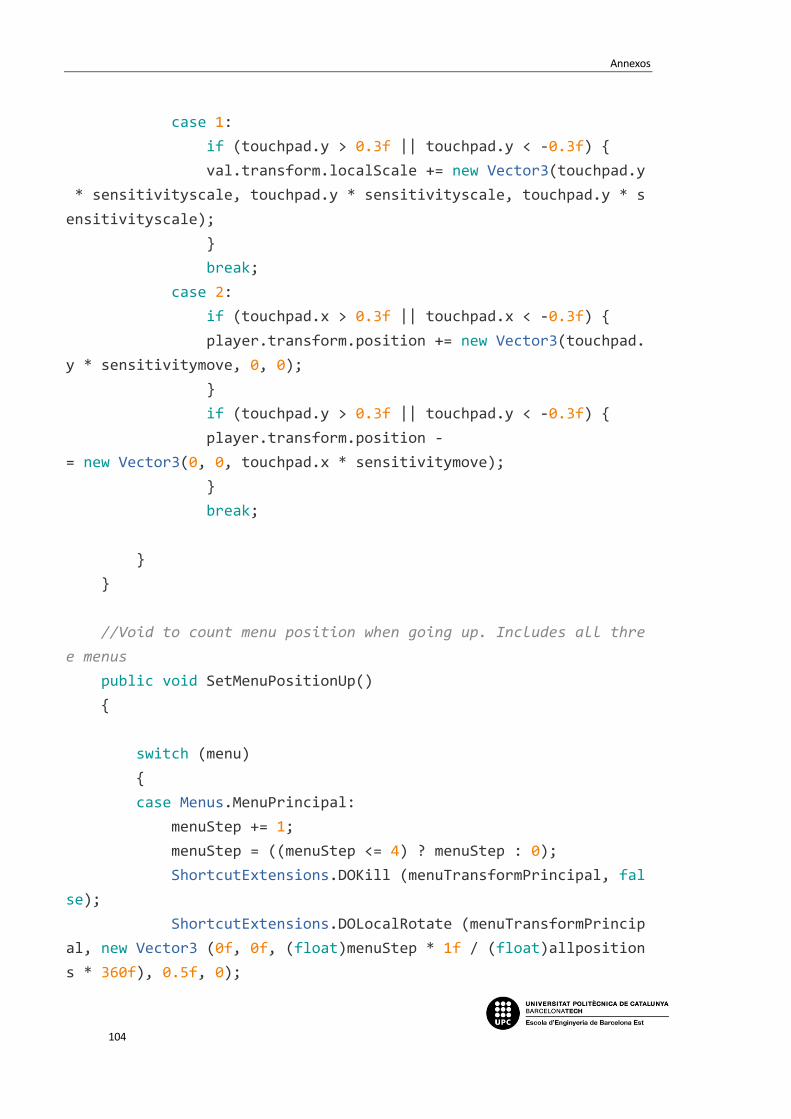
Annexos
104
case 1:
if (touchpad.y > 0.3f || touchpad.y < -0.3f) {
val.transform.localScale += new Vector3(touchpad.y
* sensitivityscale, touchpad.y * sensitivityscale, touchpad.y * s
ensitivityscale);
}
break;
case 2:
if (touchpad.x > 0.3f || touchpad.x < -0.3f) {
player.transform.position += new Vector3(touchpad.
y * sensitivitymove, 0, 0);
}
if (touchpad.y > 0.3f || touchpad.y < -0.3f) {
player.transform.position -
= new Vector3(0, 0, touchpad.x * sensitivitymove);
}
break;
}
}
//Void to count menu position when going up. Includes all thre
e menus
public void SetMenuPositionUp()
{
switch (menu)
{
case Menus.MenuPrincipal:
menuStep += 1;
menuStep = ((menuStep <= 4) ? menuStep : 0);
ShortcutExtensions.DOKill (menuTransformPrincipal, fal
se);
ShortcutExtensions.DOLocalRotate (menuTransformPrincip
al, new Vector3 (0f, 0f, (float)menuStep * 1f / (float)allposition
s * 360f), 0.5f, 0);

Virtual Reality applied to biomedical engineering
105
break;
case Menus.MenuInteracciones:
menuInteractionStep +=1 ;
menuInteractionStep = ((menuInteractionStep <= 4) ? me
nuInteractionStep : 0);
ShortcutExtensions.DOKill(menuTransformInteractions, f
alse);
ShortcutExtensions.DOLocalRotate(menuTransformInteract
ions, new Vector3(0f, 0f, (float) menuInteractionStep * 1f / (floa
t) allpositions * 360f), 0.5f, 0);
break;
case Menus.MenuImport:
menuImportStep +=1;
menuImportStep = ((menuImportStep <= 4) ? menuImportSt
ep : 0);
ShortcutExtensions.DOKill(menuTransformImport, false);
ShortcutExtensions.DOLocalRotate(menuTransformImport,
new Vector3(0f, 0f, (float)menuImportStep * 1f / (float)allpositio
ns * 360f), 0.5f, 0);
break;
}
}
//Void to count menu position when going down. Includes all th
ree menus
public void SetMenuPositionDown()
{
switch (menu)
{
case Menus.MenuPrincipal:
menuStep += -1;
menuStep = ((menuStep >= 0) ? menuStep : (allpositions
- 1));
ShortcutExtensions.DOKill(menuTransformPrincipal, fals
e);
ShortcutExtensions.DOLocalRotate(menuTransformPrincipa

Annexos
106
l, new Vector3(0f, 0f, (float)menuStep * 1f / (float)allpositions
* 360f), 0.5f, 0);
break;
case Menus.MenuInteracciones:
menuInteractionStep += -1;
menuInteractionStep = ((menuInteractionStep >= 0) ? me
nuInteractionStep : (allpositions - 1));
ShortcutExtensions.DOKill(menuTransformInteractions, f
alse);
ShortcutExtensions.DOLocalRotate(menuTransformInteract
ions, new Vector3(0f, 0f, (float)menuInteractionStep * 1f / (float
)allpositions * 360f), 0.5f, 0);
break;
case Menus.MenuImport:
menuImportStep += -1;
menuImportStep = ((menuImportStep >= 0) ? menuImportSt
ep : (allpositions - 1));
ShortcutExtensions.DOKill(menuTransformImport, false);
ShortcutExtensions.DOLocalRotate(menuTransformImport,
new Vector3(0f, 0f, (float)menuImportStep * 1f / (float)allpositio
ns * 360f), 0.5f, 0);
break;
}
}
//Void called when player presses the left controller trigger
private void OnClick()
{
switch (menu)
{
//Switch step inside main menu. All the functions in this
one need the trigger to be called
case Menus.MenuPrincipal:
{
Virtual Reality applied to biomedical engineering
107
int num2 = menuStep;
if (num2 == 1)
{
GoToInteractions();
}
if (num2 == 0)
{
GoToImport();
}
if (num2 == 2)
{
LangChange ();
}
if (num2 == 3)
{
if (!Guide)
{
Guide.SetActive(true);
}else
{
Guide.SetActive(false);
}
}
if (num2 == 4)
{
if (!Controls)
{
Controls.SetActive(true);
}else
{
Controls.SetActive(false);
}
}
break;
}

Annexos
108
//Switch step for interactions selectables. Capture sc
reen and back functions need trigger press to be called
case Menus.MenuInteracciones:
{
int num = menuInteractionStep;
if (num == 3)
{
screenshot.Capture();
}
if (num == 4)
{
GoFromInteractionToPrincipal();
}
break;
}
//Switch step for import menu. A model will be loaded
depending on the number selected
case Menus.MenuImport:
{
int num3 = menuImportStep;
if (num3 ==0)
{
import.UnloadHeart();
import.Import("0");
}
if (num3 ==1)
{
import.UnloadHeart();
import.Import("1");
}
if (num3 == 2)
{
import.UnloadHeart();
import.Import("2");
}

Virtual Reality applied to biomedical engineering
109
if (num3 == 3)
{
import.UnloadHeart();
import.Import("3");
}
if (num3 == 4)
{
GoFromImportToPrincipal();
}
break;
}
}
}
// Void reaction after pressing interactions selectable
private void GoToInteractions()
{
menuTransformPrincipal.DOScale (Vector3.zero, 0.3f);
menuTransformPrincipal.gameObject.SetActive (false);
menuTransformInteractions.gameObject.SetActive (true);
ShortcutExtensions.DOScale(menuTransformInteractions, Vect
or3.one*(0.05f), 0.3f);
menu = Menus.MenuInteracciones;
}
// Void reaction after pressing import selectable
private void GoToImport()
{
ShortcutExtensions.DOScale (menuTransformPrincipal, Vector
3.zero, 0.3f);
menuTransformPrincipal.gameObject.SetActive (false);
menuTransformImport.gameObject.SetActive (true);
ShortcutExtensions.DOScale(menuTransformImport, Vector3.on
e*(0.05f), 0.3f);
menu = Menus.MenuImport;

Annexos
110
}
// Void reaction after pressing back button from interaction m
enu
private void GoFromInteractionToPrincipal()
{
ShortcutExtensions.DOScale(menuTransformInteractions, Vect
or3.zero, 0.3f);
menuTransformInteractions.gameObject.SetActive (false);
menuTransformPrincipal.gameObject.SetActive (true);
ShortcutExtensions.DOScale(menuTransformPrincipal, Vector3
.one*(0.05f), 0.3f);
menuInteractionStep = 0;
menu = Menus.MenuPrincipal;
}
// Void reaction after pressing back button from import menu
private void GoFromImportToPrincipal()
{
ShortcutExtensions.DOScale(menuTransformImport, Vector3.ze
ro, 0.3f);
menuTransformImport.gameObject.SetActive (false);
menuTransformPrincipal.gameObject.SetActive (true);
ShortcutExtensions.DOScale(menuTransformPrincipal, Vector3
.one*(0.05f), 0.3f);
menuImportStep = 0;
menu = Menus.MenuPrincipal;
}
// Void made to change the language enum. Called when language
option is selected
private void LangChange()
{
if (lang = Language.English){
lang = Language.Spanish;

Virtual Reality applied to biomedical engineering
111
}else if (lang = Language.Spanish){
lang = Language.Catalan;
}else{
lang = Language.English;
}
}
}
A2. ImportManager
using UnityEngine;
using System.Collections;
using Valve.VR;
public class ImportManager : MonoBehaviour
{
public Material Cor;
//Function called to load the object
//The string "cor" has to be a number between 0 and 4 so the m
odels can be loaded and so there can be interaction
public void Import (string cor)
{
GameObject obj = Resources.Load(cor) as GameObject;
GameObject clone = Instantiate(obj, new Vector3(4, 2,
-4), Quaternion.identity);
clone.transform.localScale = Vector3.one * 0.025f;
clone.name = "Cor";
clone.GetComponent<Renderer>().material = Cor;
}
//Destroys the loaded heart so a new one can be charged
public void UnloadHeart()
{
GameObject cor = GameObject.Find ("Cor");
Destroy (cor);

Annexos
112
}
//
}

Virtual Reality applied to biomedical engineering
113
A3. Screenshot
using UnityEngine;
using System.Collections;
using System.IO;
public class Screenshot : MonoBehaviour {
Texture2D screenCap;
Texture2D border;
bool shot = false;
public SteamVR_Controller.Device device;
public SteamVR_TrackedObject controller;
// Use this for initialization
void Start () {
screenCap = new Texture2D(845, 460, TextureFormat.RGB24, f
alse); // 1
border = new Texture2D(2, 2, TextureFormat.ARGB32, false);
// 2
border.Apply();
controller = gameObject.GetComponent<SteamVR_TrackedObject
>();
}
// Update is called once per frame
void Update () {
device = SteamVR_Controller.Input((int)controller.index);
if (device.GetPressDown(SteamVR_Controller.ButtonMask.Trig
ger)) {
StartCoroutine("Capture");
Capture();
}

Annexos
114
}
public void OnGUI(){
//GUI.DrawTexture(new Rect(2, 0, 850, 2), border, ScaleMod
e.StretchToFill); // top
//GUI.DrawTexture(new Rect(2, 470, 850, 2), border, ScaleM
ode.StretchToFill); // bottom
//GUI.DrawTexture(new Rect(0, 0, 2, 470), border, ScaleMod
e.StretchToFill); // left
//GUI.DrawTexture(new Rect(840, 0, 2, 470), border, ScaleM
ode.StretchToFill); // right
//Puts a small capture of the screenshot in the top left o
f the screen for preview
if(shot)
{
GUI.DrawTexture(new Rect(10, 10, 60, 40), screenCap, S
caleMode.StretchToFill);
}
}
//Void to select area of the screen to be captured and where t
o be saved
public IEnumerator Capture(){
yield return new WaitForEndOfFrame();
screenCap.ReadPixels(new Rect(0, 0, 845, 840), 0, 0);
screenCap.Apply();
// Encode texture into PNG
byte[] bytes = screenCap.EncodeToPNG();
// Object.Destroy(screenCap);
// For testing purposes, also write to a file in the proje
ct folder
File.WriteAllBytes(Application.dataPath + "/SavedScreen.pn
g", bytes);

Virtual Reality applied to biomedical engineering
115
//If the photo has been taken, it can be shown in the top
left border
shot = true;
}
}

Annexos
116