virtual mobile core placement for metro...
TRANSCRIPT

Virtual Mobile Core Placement for
Metro Area
BY
ABHISHEK GUPTA
FRIDAY GROUP MEETING
JANUARY 5, 2018

Motivation
• Volume of data to be transported across a mobile network
keeps increasing
• Traditional EPC is centralized and requires constant
upgrading of mobile core (both EPC functions and
backhaul)
• Network Function Virtualization (NFV) tries to resolve
above challenges by virtualizing the mobile core ( virtual
EPC (vEPC))
• Distributing vEPC in the core reduces bandwidth
consumption and is essential for Multi-Access Edge
Computing (MEC)
2

Difference from previous work
• Mobile core is critical for connecting User Equipment (UE) to
Internet and vice-versa
• Mobile core is also critical for functioning of the Radio Access
Network (RAN)
• Here, Service Chain (SCs) result from looking at interaction of
various mobile core elements whereas earlier SCs were actual
value-added services
3

Mobile Core Architecture (Evolved Packet Core
(EPC))
4[1] Introduction to Evolved Packet Core (EPC) – EPC elements, protocols and procedures –
Alcatel Lucent

Control and Data Plane Elements of EPC
• Exclusively Control Plane Elements
• Mobility Management Element (MME)
• Policy and Charging Rules Function (PCRF)
• Home Subscriber Server (HSS)
• Data Plane Elements
• Serving Gateway (SGW)
• Packet Data Network Gateway (PGW)
5

Data Path Setup
• Traffic passes from UE to PGW (upload) or from PGW to UE
(download)
• Setup of path requires control signaling (Non-Access Stratum
(NAS) procedure)
• Control signaling is a set of chained requests which we realize
as the control service chain
• Data path also requires the SGW->PGW traversal for download
and PGW->SGW traversal for upload
6

EPC Procedures Summary
7[3] Understanding the bottlenecks in Virtualizing Cellular Core Network Functions – Intel
Labs, Connectem, AT&T Labs
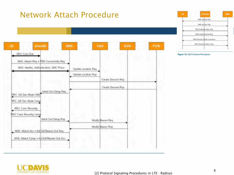
Network Attach Procedure
8[[2] Protocol Signaling Procedures in LTE - Radisys

Chained Requests (Control Plane)
9
UE
MME UE MME UE MME UE MME HSS MME PGW MME SGW
MME
UE
MME
MME HSS MME PGW MME SGW MME
Control Plane Service Chain with EPC elements only
[[2] Protocol Signaling Procedures in LTE - Radisys
Control Plane Service Chain
Directed Acyclic Graph (DAG)
MME(1)
HSS(1)
PGW(1)
SGW (1)

Chained Requests (Control Plane + Data Plane)
10
Downlink Chain
Uplink Chain
MME HSS MME PGW MME SGW MME PGW SGW
MME HSS MME PGW MME SGW MME SGW PGW
[1] Introduction to Evolved Packet Core (EPC) – EPC elements, protocols and procedures –

vEPC placement
11
Traffic Aggregation
Point (TAP)
Internet
VoIP
CDN/Video
CDN/Video
(MEC Scenario)
1. NAS Procedure (Attach,
S1-handover etc.)
2. Downlink (PGW-SGW)
3. Application (CDN/Video)
4. Latency = Application +
Control Plane Setup
1. No NAS Procedure
2. Downlink (PGW-SGW)
3. Application (CDN/Video)
4. Latency = Application
1. No NAS Procedure
2. Downlink (PGW-SGW)
3. Application (CDN/Video)
4. Latency = Application
1. NAS Procedure (Attach,
S-1 handover etc.)
2. Uplink (SGW-PGW)
3. Application (CDN/Video)
4. Latency = Application +
Control Plane Setup
1. No NAS Procedure
2. Uplink (SGW-PGW)
3. Application (CDN/Video)
4. Latency = Application

Problem Statement
• To determine the placement of mobile core element VNFs and
traffic routing to minimize the network-resource (bandwidth)
consumption, given:
• Network topology, capacity of links
• Set of NFV nodes
• Number of NFV nodes that can be used
• Aggregated traffic flows
• Using a Non-Access Stratum (NAS) procedure (attach, handover)
• Requesting a service (voice, video, data)
• Downlink/Uplink
• Number of Replicas of each VNF
• Latency requirement of services
• Latency requirement of control signaling
• Processing delay of VNFs
• Propagation delay
12

Output
• Location of vEPC elements
• Routing of traffic flows to/from application gateway
from/to Traffic Aggregation Points (TAPs)
13

Continued…
• Aggregated traffic flows from and to Traffic Aggregation
Points (TAPs) with data plane traffic (D) and control plane
traffic being a fraction of it (x*D)
• Download with NAS procedure (DNAS)
• Upload with NAS procedure (UNAS)
14
s sSG
W
PG
W d
xD xD xD xD D D D
Control Plane Service Chain Data Plane Service Chain
d dPG
W
SG
W d
xD xD xD xD D D
Control Plane Service ChainData Plane Service Chain
s
D0
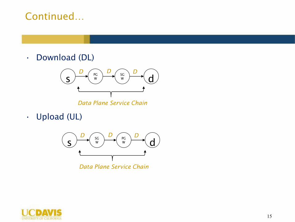
Continued…
• Download (DL)
• Upload (UL)
15
sPG
W
SG
W d
D D D
Data Plane Service Chain
sSG
W
PG
W d
D D D
Data Plane Service Chain

Continued..
• To simplify modeling, each aggregated traffic flow, NAS
procedure, uplink/downlink, application request is
considered a distinct service chain, where source (s) and
destination (d) are also VNFs with location constraints
16
s sP
G
W
S
G
W d1
xD xD xD xD D D D
Control Plane Service Chain Data Plane Service Chain
Voice
c1
s sP
G
W
S
G
W d2
xD xD xD xD D D D
Control Plane Service Chain Data Plane Service Chain
Voice
c2

Latency
• Control Plane Latency
• Bearer Setup Latency
• Default Bearer (Attach NAS Procedure) – 500ms
• Dedicated Bearer (Service Request NAS Procedure) – 250 ms
17[1] Introduction to Evolved Packet Core (EPC) – EPC elements, protocols and
procedures – Alcatel Lucent

Continued…
• Data Plane Latency
• Propagation delay
• Processing delay
18[2] Applying NFV and SDN to LTE Mobile Core Gateways; The Functions Placement
Problem – A. Basta, W. Keller, M. Hoffmann, H. J. Morper, K. Hoffmann

Delay Budget for Applications
19[3] LTE Design and Deployment Strategies – Z. Savic, Cisco
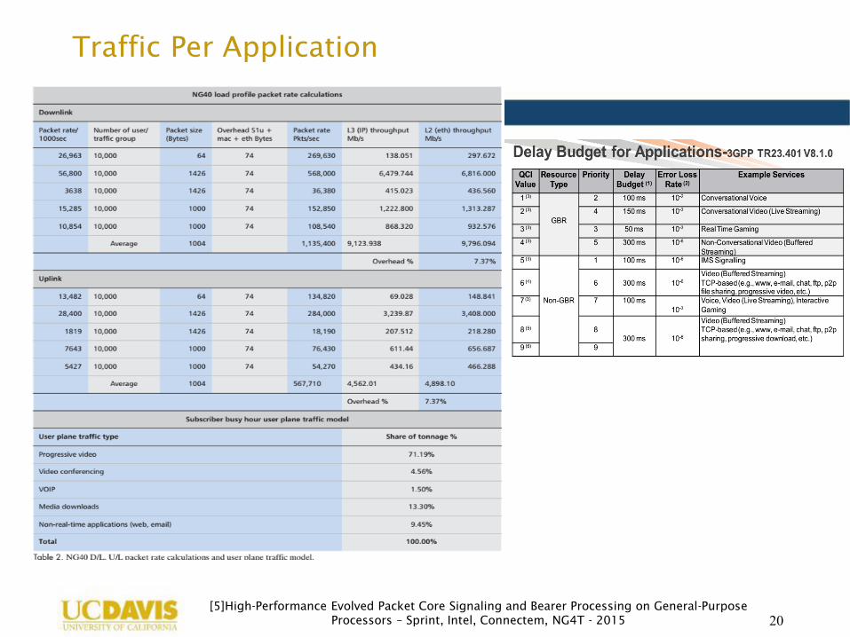
Traffic Per Application
20[5]High-Performance Evolved Packet Core Signaling and Bearer Processing on General-Purpose
Processors – Sprint, Intel, Connectem, NG4T - 2015

Simulation Settings
21
1
2
3
18
17 5
4
19
166
11 1015
7
8
912
13
14
Non-real-time
application
VoIP
Video (Live
Streaming)
Video
(Progressive
Video)
Media
downloads
Video
(Progressive
Video)
Video
(Progressive
Video)

CPU-to-throughput Relationship (2 CPUs/Gbps)
22[6] Data Sheet Brocade vEPC

Traffic flow generation
• Busy hour tonnage : 224 Gb [5]
• Upload/Download ratio : 0.25
• Traffic aggregation aggregates1000-5000 UEs
• Application traffic separation as per [5]
23[5] High-Performance Evolved Packet Core Signaling and Bearer Processing on General-
Purpose Processors – Sprint, Intel, Connectem, NG4T - 2015
NAS event Number of flows
Attach 10
Service Request 45
X2-based 5
S1-based 10
No NAS event (pure data plane)
50

Other simulation parameters
• Per link bandwidth: 60 Gb
• CPU Cores per node: 2400
• Control traffic: 5%
• Simulation runs are done 10 times and the mean across
the iteration is plotted
24

Reduction in bandwidth consumption as replicas
increase
25

Not all EPC VNFs need to be distributed (only SGW,
PGW)
26

Not all EPC VNFs need to be distributed (only SGW,
PGW)
27