virtual interface architecture specification - uml.edubill/cs520/vi_spec.pdf · virtual interface...
TRANSCRIPT
Virtual Interface ArchitectureSpecification
Version 1.0December 16, 1997
THIS SPECIFICATION IS PROVIDED “AS IS” WITH NO WARRANTIES WHATSOEVER,WHETHER EXPRESS, IMPLIED OR STATUTORY, INCLUDING, BUT NOT LIMITED TO ANYWARRANTY OF MERCHANTABILITY, NONINFRINGEMENT, FITNESS FOR ANY PARTICULARPURPOSE, OR ANY WARRANTY OTHERWISE ARISING OUT OF ANY PROPOSAL,SPECIFICATION, OR SAMPLE. ANY DESIGNS OR IMPLEMENTATIONS BASED ON VERSION1.0 OF THIS SPECIFICATION ARE DONE AT THE DESIGNERS OR IMPLEMENTERS OWN RISK.
1997 Compaq Computer Corp., Intel Corporation, Microsoft Corporation.
VI Architecture Specification
Page 2
Table of Contents1. Introduction................................................................................................................................5
1.1. Overview ............................................................................................................................51.2. Purpose..............................................................................................................................51.3. Architectural Scope............................................................................................................61.4. Document Scope ...............................................................................................................61.5. Terminology .......................................................................................................................6
1.5.1. Acronyms and Abbreviations......................................................................................61.5.2. Industry Terms............................................................................................................71.5.3. VI Architecture Terms.................................................................................................8
2. VI Architecture Overview.........................................................................................................112.1. VI Architecture Components ............................................................................................11
2.1.1. Virtual Interfaces.......................................................................................................122.1.2. VI Provider ................................................................................................................132.1.3. VI Consumer.............................................................................................................14
2.2. Memory Registration........................................................................................................142.3. Data Transfer Models ......................................................................................................14
2.3.1. Send/Receive ...........................................................................................................142.3.2. Remote Direct Memory Access (RDMA) ..................................................................15
2.4. Completion Queues .........................................................................................................152.5. Reliability Levels ..............................................................................................................16
2.5.1. Unreliable Delivery....................................................................................................172.5.2. Reliable Delivery.......................................................................................................182.5.3. Reliable Reception....................................................................................................18
2.6. System Area Networks ....................................................................................................183. Managing VI Components.......................................................................................................20
3.1. Accessing a VI NIC ..........................................................................................................203.2. Memory Management ......................................................................................................20
3.2.1. Registering and De-registering Memory...................................................................203.2.2. Memory Protection....................................................................................................21
3.3. Creating and Destroying VIs ............................................................................................213.4. Creating and Destroying Completion Queues .................................................................22
4. VI Connection and Disconnection...........................................................................................234.1. VI Connection ..................................................................................................................234.2. VI Disconnection ..............................................................................................................244.3. VI Address Format ...........................................................................................................25
5. VI States..................................................................................................................................265.1. Idle State ..........................................................................................................................265.2. Pending Connect State ....................................................................................................275.3. Connected State ..............................................................................................................275.4. Error State........................................................................................................................28
6. Descriptor Processing Model ..................................................................................................296.1. Forming Descriptors.........................................................................................................29
6.1.1. Data Considerations .................................................................................................306.2. Posting Descriptors..........................................................................................................306.3. Processing Descriptors ....................................................................................................30
6.3.1. Ordering Rules and Barriers.....................................................................................316.3.2. Address Translation and Memory Access................................................................32
6.4. Completing Descriptors....................................................................................................326.4.1. Completing Descriptors by the VI Provider...............................................................326.4.2. Completing Descriptors by the VI Consumer ...........................................................33
7. Error Handling .........................................................................................................................347.1. Error Handling for Unreliable Connections ......................................................................347.2. Error Handling for Reliable Delivery Connections ...........................................................347.3. Error Handling for Reliable Reception Connections ........................................................34

VI Architecture Specification
Page 3
8. Guidelines ...............................................................................................................................358.1. Scalability .........................................................................................................................35
9. Appendix A..............................................................................................................................369.1. Example VI User Agent Overview....................................................................................369.2. Hardware Connection ......................................................................................................36
9.2.1. VipOpenNic...............................................................................................................369.2.2. VipCloseNic ..............................................................................................................36
9.3. Endpoint Creation and Destruction..................................................................................379.3.1. VipCreateVi...............................................................................................................379.3.2. VipDestroyVi .............................................................................................................38
9.4. Connection Management.................................................................................................399.4.1. VipConnectWait ........................................................................................................399.4.2. VipConnectAccept ....................................................................................................409.4.3. VipConnectReject .....................................................................................................409.4.4. VipConnectRequest..................................................................................................419.4.5. VipDisconnect...........................................................................................................42
9.5. Memory protection and registration .................................................................................429.5.1. VipCreatePtag ..........................................................................................................429.5.2. VipDestroyPtag.........................................................................................................439.5.3. VipRegisterMem .......................................................................................................449.5.4. VipDeregisterMem....................................................................................................45
9.6. Data transfer and completion operations.........................................................................459.6.1. VipPostSend .............................................................................................................459.6.2. VipSendDone............................................................................................................469.6.3. VipSendWait .............................................................................................................469.6.4. VipPostRecv .............................................................................................................479.6.5. VipRecvDone............................................................................................................489.6.6. VipRecvWait .............................................................................................................489.6.7. VipCQDone...............................................................................................................499.6.8. VipCQWait ................................................................................................................509.6.9. VipSendNotify ...........................................................................................................519.6.10. VipRecvNotify ...........................................................................................................529.6.11. VipCQNotify ..............................................................................................................53
9.7. Completion Queue Management.....................................................................................549.7.1. VipCreateCQ ............................................................................................................549.7.2. VipDestroyCQ...........................................................................................................549.7.3. VipResizeCQ ............................................................................................................55
9.8. Querying Information .......................................................................................................569.8.1. VipQueryNic..............................................................................................................569.8.2. VipSetViAttributes.....................................................................................................569.8.3. VipQueryVi................................................................................................................579.8.4. VipSetMemAttributes ................................................................................................579.8.5. VipQueryMem...........................................................................................................589.8.6. VipQuerySystemManagementInfo............................................................................59
9.9. Error handling...................................................................................................................599.9.1. VipErrorCallback.......................................................................................................59
9.10. Data Structures and Values .........................................................................................619.10.1. Return Codes............................................................................................................619.10.2. VI Descriptor .............................................................................................................619.10.3. Error Descriptor ........................................................................................................639.10.4. NIC Attributes ...........................................................................................................649.10.5. VI Attributes ..............................................................................................................659.10.6. Memory Attributes.....................................................................................................669.10.7. VI Endpoint State......................................................................................................669.10.8. VI Network Address ..................................................................................................67
10. Appendix B ..........................................................................................................................68

VI Architecture Specification
Page 4
10.1. Example Descriptor Format Overview .........................................................................6810.2. Descriptor Control Segment.........................................................................................6910.3. Descriptor Address Segment .......................................................................................7310.4. Descriptor Data Segment .............................................................................................73
11. Appendix C ..........................................................................................................................7411.1. Example Hardware Model Overview............................................................................7411.2. Example VI NIC............................................................................................................74
11.2.1. Hardware Interface ...................................................................................................7511.2.2. NIC Hardware Functions ..........................................................................................79
11.3. Kernel Agent Example..................................................................................................8011.3.1. NIC Initialization........................................................................................................8111.3.2. Interrupt Processing..................................................................................................8111.3.3. Memory Registration.................................................................................................8111.3.4. Memory De-registration ............................................................................................8111.3.5. Setting and Querying Memory Attributes..................................................................8111.3.6. VI Creation................................................................................................................8111.3.7. VI Destruction ...........................................................................................................8111.3.8. Setting and Querying VI Attributes ...........................................................................8211.3.9. Protection Tag Creation............................................................................................8211.3.10. Protection Tag Destruction ...................................................................................8211.3.11. Connection Management......................................................................................8211.3.12. Block on Send and Receive..................................................................................8211.3.13. Create Completion Queue ....................................................................................8211.3.14. Resize Completion Queue ....................................................................................8211.3.15. Block on Completion Queue .................................................................................8311.3.16. Destroy Completion Queue...................................................................................8311.3.17. Error Callback .......................................................................................................8311.3.18. Resource cleanup .................................................................................................83

VI Architecture Specification
Page 5
1. Introduction
1.1. OverviewThis document describes an architecture for the interface between high performance networkhardware and computer systems. The goal of this architecture is to improve the performance ofdistributed applications by reducing the latency associated with critical message passingoperations. This goal is attained by substantially reducing the system software processingrequired to exchange messages compared to traditional network interface architectures. Thisdesign is called the Virtual Interface (VI) Architecture.
This document is divided into several parts. They are arranged as follows:
Chapter 1 – Introduction.
This chapter describes the architecture’s purpose and scope. It also lays a foundationwith definitions of some terms.
Chapter 2 – VI Architecture Overview.
This chapter identifies the main components and key features of the VI Architecture.
Chapters 3 to 8
These chapters describe the semantics, behavior and features of the VI Architecture indetail.
Appendix A
As an aid to hardware implementers, this section contains examples of how the VIArchitecture might be interfaced to operating system communication facilities.
Appendix B
This section describes an example VI Descriptor format.
Appendix C
This section describes an example design for a VI enabled network interface controllerand a functional description of a VI Kernel Agent.
1.2. PurposeDistributed applications require the rapid and reliable exchange of information across a networkto synchronize operations and/or to share data. The performance and scalability of theseapplications depend upon an efficient communication facility.
Traditional network architectures do not provide the performance required by these applications,largely due to the host-processing overhead of kernel-based transport stacks. This processingoverhead has a negative performance impact in several ways:
• Bandwidth - the overhead limits the actual bandwidth that a given network can deliver.Network hardware bandwidths are increasing by orders of magnitude, while softwareoverhead in available networking stacks remains relatively constant.
• Latency and Synchronization - efficient synchronization is a major scalability factor fordistributed and network-based applications. The overhead directly contributes to end-to-endlatency of messages used for synchronization.
• Host processing load - the overhead consumes CPU cycles that could be used for otherprocessing.

VI Architecture Specification
Page 6
These problems are addressed in the VI Architecture by moving the network interface muchcloser to the application, increasing its functionality, and better matching its features to applicationrequirements. The result is a substantial reduction in processing overhead along thecommunication paths that are critical to performance.
1.3. Architectural ScopeThis specification defines an architecture for an interface between high performance networkhardware and computer systems. The following items are within the scope of the specification:
• Logical and physical components that comprise the interface.
• Semantics/behavior seen by consumers and providers of the interface.
• Operations required of the interface components. The critical data movement operations arecovered in detail. Supporting operations, such as connection establishment, are covered inmore general terms.
• Example software interface to illustrate how software could interact with the VI hardware.
• Example design for network hardware that supports the interface architecture. Implementersare not required to utilize this design.
The following items are outside the scope of the specification:
• Specification of the implementation details of the VI Architecture components. Thisinformation is operating system and network hardware specific. Implementations may vary aslong as the specified behavior is maintained.
• The programming interface used by applications to access hardware that supports the VIArchitecture. This interface is operating system specific. It is expected that operating systemvendors will issue companion documents that specify mappings of their programminginterfaces onto the VI Architecture.
• Absolute values for performance and reliability. General guidelines based on the strength ofthe architecture are specified, allowing for variance from one implementation to another.
1.4. Document ScopeThis document serves two audiences: network hardware vendors and operating system vendors.This document is not intended for applications programmers that use services built on top of theVI Architecture.
1.5. Terminology
1.5.1. Acronyms and AbbreviationsAPI Application Programming Interface. A collection of function calls exported by
libraries and/or services.
CRC Cyclic Redundancy Check. A number derived from, and stored or transmittedwith, a block of data in order to detect corruption. By recalculating the CRC andcomparing it to the value originally transmitted, the receiver can detect sometypes of transmission errors.
DMA Direct Memory Access. A facility that allows a peripheral device to read and writememory without intervention by the CPU.
IHV Independent Hardware Vendor. Any vendor providing hardware. Usedsynonymously at times with VI Hardware Vendor.

VI Architecture Specification
Page 7
MTU Maximum Transfer Unit. The largest frame length that may be sent on a physicalmedium.
NIC Network Interface Controller. A NIC provides an electro-mechanical attachmentof a computer to a network. Under program control, a NIC copies data frommemory to the network medium, transmission, and from the medium to memory,reception, and implements a unique destination for messages traversing thenetwork.
OSV Operating System Vendor. The software manufacturer of the operating systemthat is running on the node under discussion.
QOS Quality of Service. Metrics that predict the behavior, speed and latency of agiven network connection.
SAN System Area Network. A high-bandwidth, low-latency network interconnectingnodes within a distributed computer system.
SAR Segmentation and Re-assembly. The process of breaking data to be transferredinto quantities that are less than or equal to the MTU, transmitting them acrossthe network and then reassembling them at the receiving end to reconstruct theoriginal data.
TCP/IP Transmission Control Protocol/Internet Protocol. A standard networking protocoldeveloped for LANs and WANs. This is the standard communication protocolused in the Internet.
VM Virtual Memory. The address space available to a process running in a systemwith a memory management unit (MMU). The virtual address space is usuallydivided into pages, each consisting of 2N bytes. The bottom N address bits (theoffset within a page) are left unchanged, indicating the offset within a page, andthe upper bits give a (virtual) page number that is mapped by the MMU to aphysical page address. This is recombined with the offset to give the address ofa location in physical memory.
1.5.2. Industry TermsCallback A scheme used in event-driven programs where the program registers a function,
called the callback handler, for a certain event. The program does not call thecallback handler directly. Rather, when the event occurs, the handler is invokedasynchronously, possibly with arguments describing the event.
Data Payload The amount of data, not including any control or header information, that can becarried in one packet.
Frame One unit of data encapsulated by a physical network protocol header and/ortrailer. The header generally provides control and routing information fordirecting the frame through the network fabric. The trailer generally containscontrol and CRC data for ensuring packets are not delivered with corruptedcontents.
Link A full duplex channel between any two network fabric elements, such as nodes,routers or switches.
Network FabricThe collection of routers, switches, connectors, and cables that connects a set ofnodes.
Message An application-defined unit of data interchange. A primitive unit of communicationbetween cooperating sequential processes.

VI Architecture Specification
Page 8
Message LatencyThe elapsed time from the initiation of a message send operation until thereceiver is notified that the entire message is present in its memory.
Message OverheadThe sum of the times required to initiate transmission of a message, notify thereceiver that the message is available, and the non-bandwidth dependentlatencies (e.g. time for a NIC to process data) incurred in moving a messagefrom the source to the destination.
Node A computer attached by a NIC to one or more links of a network, and forming theorigin and/or destination of messages within the network.
Packet A primitive unit of data interchange between nodes, comprised of a set of datasegments transmitted in an ordered stream. A packet may be sent as a singleframe, or may be fragmented into smaller units (cells) such that cells for variouspackets may be interleaved in the fabric but the transmission order of cells for apacket is preserved and manifest as a contiguous unit at a receiving node.
Server The class of computers that emphasize I/O connectivity and centralized datastorage capacity to support the needs of other, typically remote, client computers.
Workstation, or ClientThe class of computers that emphasize numerical and/or graphic performanceand provide an interface to a human being.
1.5.3. VI Architecture Terms
The following terms are introduced in this document.
Address SegmentThe second of the three segments that comprise a remote-DMA operationDescriptor, specifying the memory region to access on the target.
Communication MemoryAny region of a process’ memory that is registered with the VI Provider to servefor storage of Descriptors and/or as communication buffers; i.e., any region of aprocess’ memory that will be accessed by the VI NIC.
Connection An association between a pair of VIs such that messages sent using either VIarrives at the other VI. A VI is either unconnected, or connected to one and onlyone other VI.
Control SegmentThe first component of a Descriptor containing information regarding the type ofVI NIC data movement operation to be performed, the status of a completed VINIC data movement operation, and the location of the next Descriptor on a WorkQueue.
Completion QueueA queue containing information about completed Descriptors. Used to create asingle point of completion notification for multiple queues.
Completion Queue EntryA single data structure on a Completion Queue that describes a completedDescriptor. This entity contains sufficient information to determine the queue thatholds the completed Descriptor.
Data Segment A component of a Descriptor specifying one memory region for the VI NIC to useas a communication buffer.

VI Architecture Specification
Page 9
Descriptor A data structure recognized by the VI NIC that describes a data movementrequest. A Descriptor is organized as a list of segments. A Descriptor iscomprised of a control segment followed by an optional address segment and anarbitrary number of data segments. The data segments describe acommunication buffer gather or scatter list for a VI NIC data movementoperation.
Doorbell A mechanism for a process to notify the VI NIC that work has been placed on aWork Queue. The Doorbell mechanism must be protected by the operatingsystem—i.e., for address protection, only the operating system should be able toestablish a Doorbell—and the VI NIC must be able to identify the owner of a VIby the use of its Doorbell.
Done The state of a Descriptor when the VI NIC has completed processing it.
Immediate DataData contained in a Descriptor that is sent along with the data to the remote nodeand placed in the remote node’s pre-posted Receive Queue Descriptor.
Kernel Agent A component of the operating system required by the VI Architecture thatsubsumes the role of the device driver for the VI NIC and includes the kernelsoftware needed to register communication memory and manage VIs.
Memory HandleA programmatic construct that represents a process’s authorization to specify amemory region to the VI NIC. A memory handle is created by the VI Kernel Agentwhen a process registers communication memory. A process must supply acorresponding Memory Handle with any virtual address to qualify it to the VI NIC.The VI NIC will not perform an access to a virtual address if the supplied memoryhandle does not agree with the memory region containing the virtual address or ifthe memory region is registered to a process other than the process that owns aVirtual Interface (VI).
Memory Protection AttributesThe access rights for RDMA granted to VIs and to Memory Regions.
Memory Protection TagA unique identifier generated by the VI Provider for use by the VI Consumer.Memory Protection Tags are associated with VIs and Memory Regions to definethe access permission the VI has to a memory region.
Memory RegionAn arbitrary sized region of a process’s virtual address space registered ascommunication memory such that it can be directly accessed by the VI NIC.
Memory RegistrationThe act of creating a memory region. The memory registration operation returns aMemory Handle that the process is required to provide with any virtual addresswithin the memory region.
VI NIC AddressThe logical network address of the VI NIC. This address is assigned to a VI NICby the operating system and allows processes within a network to identify aremote node with respect to a VI NIC attachment of the remote node to thenetwork.
NIC Handle A programmatic construct representing a process’s authorization to performcommunication operations using a local VI NIC.
Outstanding The state of a Descriptor after it has been posted on a Work Queue, but before itis Done. This state represents the interval of time between a process posting aDescriptor and the completion of the Descriptor by the VI NIC.
VI Architecture Specification
Page 10
Peer A generic term for the process at the other end of a connection.
Post To place a Descriptor on a VI Work Queue.
RDMA Remote Direct Memory Access. A Descriptor operation whereby data in a localgather or scatter list is moved directly to or from a memory region on a remotenode. A process authorizes remote access to its memory by creating a VI withremote-DMA operations enabled, connecting it to a remote VI, and making thememory handle for the memory region to be shared available to the peer that willperform the remote-DMA operation. There are two remote-DMA operations: writeand read.
Receive QueueOne of the two queues associated with a VI. This queue contains Descriptorsthat describe where to place incoming data.
Retired The state of a Descriptor after the VI NIC completes the operation specified bythe Descriptor, but before the done operation has been used to synchronize theprocess with the status stored in the Descriptor.
Send Queue One of the two queues associated with a VI. This queue contains Descriptorsthat describe the data to be transmitted.
User Agent A software component that enables an Operating System communication facilityto utilize a particular VI Provider. The VI User Agent abstracts the details of theunderlying VI NIC hardware in accordance with an interface defined by theOperating System communication facility.
VI Virtual Interface. An interface between a VI NIC and a process allowing a VI NICdirect access to the process’ memory. A VI consists of a pair of Work Queues—one for send operations and one for receive operations. The queues store aDescriptor between the time it is posted and the time it is Done. A pair of VIs areassociated using the connect operation to allow packets sent at one VI to bereceived at the other.
VI Address The logical name for a VI . The VI address identifies a remote end-point to beassociated with a local end-point using the connect-VI operation.
VI Consumer A software process that communicates using a Virtual Interface. The VIConsumer typically consists of an application program, an Operating Systemcommunications facility, and a VI User Agent.
VI Handle A programmatic construct that represents a processes authorization to performoperations on a specific VI. A VI handle is returned by the operation that createsthe VI and is supplied as an identifier parameter to the other VI operations.
VI Hardware VendorAnyone who produces a VI Architecture enabled NIC implementation. Thevendor is responsible for providing the VI NIC, VI Kernel Agent and the VI UserAgent.
VI NIC A Network Interface Card that complies with the VI Architecture Specification.
VI Provider The combination of a VI NIC and a VI Kernel Agent. Together, these twocomponents instantiate a Virtual Interface.
Work Queue A posted list of Descriptors being processed by a VI NIC. Every VI has two WorkQueues: a send queue and a receive queue. The combination of the Work Queueselected by a post operation and the operation type indicated by the Descriptordetermine the exact type of data movement that the VI NIC will perform.

VI Architecture Specification
Page 11
2. VI Architecture OverviewIn the traditional network architecture, the operating system (OS) virtualizes the networkhardware into a set of logical communication endpoints available to network consumers. The OSmultiplexes access to the hardware among these endpoints. In most cases, the operating systemalso implements protocols that make communication between connected endpoints reliable. Thismodel permits the interface between the network hardware and the operating system to be verysimple. The drawback of this organization is that all communication operations require a call ortrap into the operating system kernel, which can be quite expensive to execute. The de-multiplexing process and reliability protocols also tend to be computationally expensive.
The VI Architecture eliminates the system-processing overhead of the traditional model byproviding each consumer process with a protected, directly accessible interface to the networkhardware - a Virtual Interface. Each VI represents a communication endpoint. VI endpoint pairscan be logically connected to support bi-directional, point-to-point data transfer. A process mayown multiple VIs exported by one or more network adapters. A network adapter performs theendpoint virtualization directly and subsumes the tasks of multiplexing, de-multiplexing, and datatransfer scheduling normally performed by an OS kernel and device driver. An adapter maycompletely ensure the reliability of communication between connected VIs. Alternately, this taskmay be shared with transport protocol software loaded into the application process, at thediscretion of the hardware vendor.
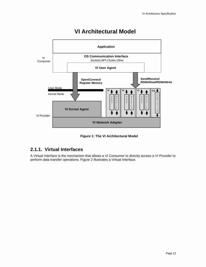
2.1. VI Architecture ComponentsThe VI Architecture is comprised of four basic components: Virtual Interfaces, CompletionQueues, VI Providers, and VI Consumers. The VI Provider is composed of a physical networkadapter and a software Kernel Agent. The VI Consumer is generally composed of an applicationprogram and an operating system communication facility. The organization of these componentsis illustrated in Figure 1.
VI Architecture Specification
Page 12
VI Architectural Model
Application
OS Communication InterfaceVI Consumer
VI Kernel Agent
VI Network Adapter
SEND
VI
RECEIVE
SEND
VI
RECEIVE
CQCOMPLETION
SEND
VI
RECEIVE
User Mode
Kernel Mode
VI Provider
Sockets,MPI,Cluster,Other
Send/Receive/RDMARead/RDMAWrite
Open/Connect/Register Memory
VI User Agent
Figure 1: The VI Architectural Model
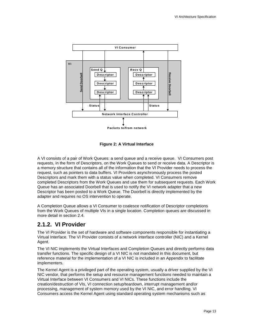
2.1.1. Virtual InterfacesA Virtual Interface is the mechanism that allows a VI Consumer to directly access a VI Provider toperform data transfer operations. Figure 2 illustrates a Virtual Interface.
VI Architecture Specification
Page 13
V I
D escriptor
S end Q Recv Q
S tatus S tatus
Sen
d D
oor
bel
l Receive D
oo
rbell
V I Consum er
D escriptor
D escriptor
D escriptor
D escriptor
D escriptor
Netw ork Interface Controller
Packets to /from network
Figure 2: A Virtual Interface
A VI consists of a pair of Work Queues: a send queue and a receive queue. VI Consumers postrequests, in the form of Descriptors, on the Work Queues to send or receive data. A Descriptor isa memory structure that contains all of the information that the VI Provider needs to process therequest, such as pointers to data buffers. VI Providers asynchronously process the postedDescriptors and mark them with a status value when completed. VI Consumers removecompleted Descriptors from the Work Queues and use them for subsequent requests. Each WorkQueue has an associated Doorbell that is used to notify the VI network adapter that a newDescriptor has been posted to a Work Queue. The Doorbell is directly implemented by theadapter and requires no OS intervention to operate.
A Completion Queue allows a VI Consumer to coalesce notification of Descriptor completionsfrom the Work Queues of multiple VIs in a single location. Completion queues are discussed inmore detail in section 2.4.
2.1.2. VI ProviderThe VI Provider is the set of hardware and software components responsible for instantiating aVirtual Interface. The VI Provider consists of a network interface controller (NIC) and a KernelAgent.
The VI NIC implements the Virtual Interfaces and Completion Queues and directly performs datatransfer functions. The specific design of a VI NIC is not mandated in this document, butreference material for the implementation of a VI NIC is included in an Appendix to facilitateimplementers.
The Kernel Agent is a privileged part of the operating system, usually a driver supplied by the VINIC vendor, that performs the setup and resource management functions needed to maintain aVirtual Interface between VI Consumers and VI NICs. These functions include thecreation/destruction of VIs, VI connection setup/teardown, interrupt management and/orprocessing, management of system memory used by the VI NIC, and error handling. VIConsumers access the Kernel Agent using standard operating system mechanisms such as

VI Architecture Specification
Page 14
system calls. Kernel Agents interact with VI NICs through standard operating system devicemanagement mechanisms.
2.1.3. VI ConsumerThe VI Consumer represents the user of a Virtual Interface. While an application program is theultimate consumer of communication services, applications access these services throughstandard operating system programming interfaces such as Sockets or MPI. The OS facility isgenerally implemented as a library that is loaded into the application process.
The OS facility makes system calls to the Kernel Agent to create a VI on the local system andconnect it to a VI on a remote system. Once a connection is established, the OS facility posts theapplication’s send and receive requests directly to the local VI. The data transfer mechanism willbe discussed further in section 2.3.
The OS communication facility often loads a library that abstracts the details of the underlyingcommunication provider, in this case the VI and Kernel Agent. This component is shown as the VIUser Agent in Figure 1. It is supplied by the VI Hardware vendor, and conforms to an interfacedefined by the OS communication facility. Appendix A illustrates an example User Agent interfacethat exposes all of the capabilities of the VI Architecture.
2.2. Memory RegistrationMost computer system designs require that the memory pages used to hold messages are lockeddown and that their virtual addresses be translated into physical locations before a NIC canaccess them. The pages are unlocked when the transfer is complete. Traditional networktransports perform these operations on every data transfer request. This processing contributessignificant overhead to the data transfer operation. The VI Architecture requires the VI Consumerto identify memory used for a data transfer prior to submitting the request. Only memory that hasbeen registered with the VI Provider can be used for data transfers. This memory registrationprocess allows the VI Consumer to reuse registered memory buffers, thereby avoiding duplicationof locking and translation operations. Memory registration also takes this processing overheadout of the performance-critical data transfer path.
Memory registration enables the VI Provider to transfer data directly between the buffers of a VIConsumer and the network without copying any data to or from intermediate buffers. Traditionalnetwork transports often copy data between user buffers and intermediate kernel buffers. Datacopies and buffer management are a large component of overhead in communication andconsume memory bandwidth.
Memory registration consists of locking the pages of a virtually contiguous memory region intophysical memory and providing the virtual to physical translations to the VI NIC. The VIConsumer gets an opaque handle for each memory region registered. The VI Consumer canreference all registered memory by its virtual address and its associated handle.
2.3. Data Transfer ModelsThere are two types of data transfer facilities provided by the Virtual Interface Architecture. Thesedata transfer models are 1) a traditional Send/Receive messaging model, and 2) the RemoteDirect Memory Access (RDMA) model.
2.3.1. Send/ReceiveThe Send/Receive model of the VI Architecture follows a well known and well understood modelof transferring data between two endpoints. In this model, the VI Consumer on the local nodealways specifies the location of the data. On the sending side, the sending process specifies thememory regions that contain the data to be sent. On the receiving side, the receiving processspecifies the memory regions where the data will be placed. Given a single connection, there is a
VI Architecture Specification
Page 15
one to one correspondence between send Descriptors on the transmitting side and receiveDescriptors on the receiving side.
The VI Consumer at the receiving end pre-posts a Descriptor to the receive queue of a VI. TheVI Consumer at the sending end can then post the message to the corresponding VI’s sendqueue. The Send/Receive model of data transfer requires that the VI Consumers be notified ofDescriptor completion at both ends of the transfer, for synchronization purposes.
VI Consumers are responsible for managing flow control on a connection. The VI Consumer onthe receiving side must post a Receive Descriptor of sufficient size before the sender’s dataarrives. If the Receive Descriptor at the head of the queue is not large enough to handle theincoming message, or the Receive Queue is empty, an error will occur. The connection may bebroken if it is intended to be reliable. See section 2.5.
The VI Architecture differs from some existing models in that all Send/Receive operationscomplete asynchronously.
2.3.2. Remote Direct Memory Access (RDMA)In the RDMA Model, the initiator of the data transfer specifies both the source buffer and thedestination buffer of the data transfer. There are two types of RDMA operations, RDMA Writeand RDMA Read.
For the RDMA Write operation, the VI Consumer specifies the source of the data transfer in oneof its local registered memory regions, and the destination of the data transfer within a remotememory region that has been registered on the remote system. The source of an RDMA Writecan be specified as a gather list of buffers, while the destination must be a single, virtuallycontiguous region. The RDMA Write operation implies that prior to the data transfer, the VIConsumer at the remote end has informed the initiator of the RDMA Write of the location of thedestination buffer, and that the buffer itself is enabled for RDMA Write operations. The remotelocation of the data is specified by its virtual address and its associated memory handle.
For the RDMA Read operation, the VI Consumer specifies the source of the data transfer at theremote end, and the destination of the data transfer within a locally registered memory region.The source of an RDMA Read operation must be a single, virtually contiguous buffer, while thedestination of the transfer can be specified as a scatter list of buffers. The RDMA Read operationimplies that prior to the data transfer, the VI Consumer at the remote end has informed theinitiator of the RDMA Read of the location of the source buffer, and that the buffer itself is enabledfor RDMA Read operations. The remote location of the data is specified by its virtual addressand its associated memory handle.
No Descriptors on the remote node’s receive queue are consumed by RDMA operations. Nonotification is given to the remote node that the request has completed. The exception to this ruleis that if Immediate Data is specified by the initiator of an RDMA Write request it will consume aDescriptor on the remote end when the data transfer is complete, thus allowing forsynchronization. The VI Consumer on the receiving side must post a Receive Descriptor toreceive the Immediate Data, before the sender executes the RDMA Write. If no Descriptor isposted, an error will occur and the connection may be broken. See Section 2.5. Immediate Datais not allowed on RDMA Reads.
RDMA Write is a required feature of the VI Architecture. VI Provider support for RDMA Read isoptional. A VI Provider should supply a mechanism by which a VI Consumer can determine if theProvider supports RDMA Read operations.
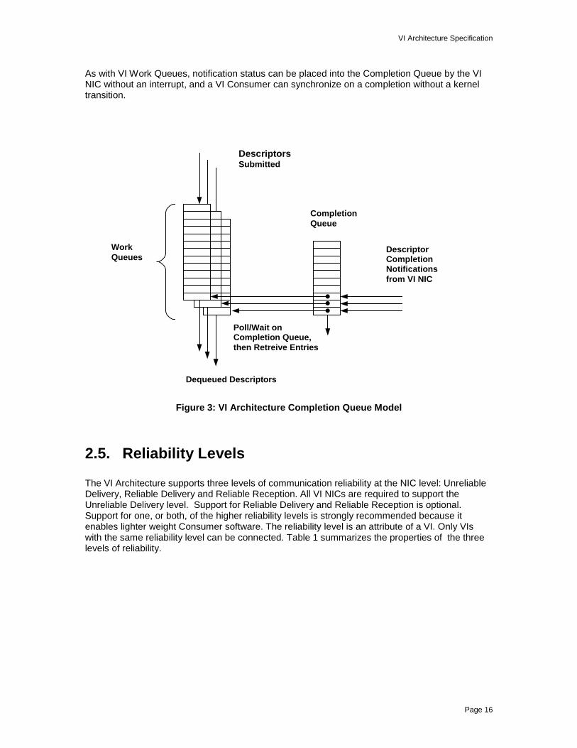
2.4. Completion QueuesNotification of completed requests can be directed to a Completion Queue on a per-VI WorkQueue basis. This association is established when a VI is created. Once a VI Work Queue isassociated with a Completion Queue, all completion synchronization must take place on thatCompletion Queue.
VI Architecture Specification
Page 16
As with VI Work Queues, notification status can be placed into the Completion Queue by the VINIC without an interrupt, and a VI Consumer can synchronize on a completion without a kerneltransition.
CompletionQueue
DescriptorCompletionNotificationsfrom VI NIC
Poll/Wait onCompletion Queue,then Retreive Entries
Dequeued Descriptors
WorkQueues
DescriptorsSubmitted
Figure 3: VI Architecture Completion Queue Model
2.5. Reliability Levels
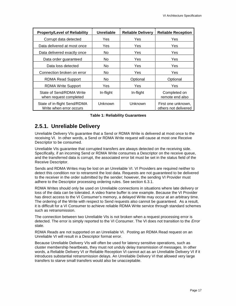
The VI Architecture supports three levels of communication reliability at the NIC level: UnreliableDelivery, Reliable Delivery and Reliable Reception. All VI NICs are required to support theUnreliable Delivery level. Support for Reliable Delivery and Reliable Reception is optional.Support for one, or both, of the higher reliability levels is strongly recommended because itenables lighter weight Consumer software. The reliability level is an attribute of a VI. Only VIswith the same reliability level can be connected. Table 1 summarizes the properties of the threelevels of reliability.
VI Architecture Specification
Page 17
Property/Level of Reliability Unreliable Reliable Delivery Reliable Reception
Corrupt data detected Yes Yes Yes
Data delivered at most once Yes Yes Yes
Data delivered exactly once No Yes Yes
Data order guaranteed No Yes Yes
Data loss detected No Yes Yes
Connection broken on error No Yes Yes
RDMA Read Support No Optional Optional
RDMA Write Support Yes Yes Yes
State of Send/RDMA Writewhen request completed
In-flight In-flight Completed onremote end also
State of in-flight Send/RDMAWrite when error occurs
Unknown Unknown First one unknown,others not delivered
Table 1: Reliability Guarantees
2.5.1. Unreliable DeliveryUnreliable Delivery VIs guarantee that a Send or RDMA Write is delivered at most once to thereceiving VI. In other words, a Send or RDMA Write request will cause at most one ReceiveDescriptor to be consumed.
Unreliable VIs guarantee that corrupted transfers are always detected on the receiving side.Specifically, if an incoming Send or RDMA Write consumes a Descriptor on the receive queue,and the transferred data is corrupt, the associated error bit must be set in the status field of theReceive Descriptor.
Sends and RDMA Writes may be lost on an Unreliable VI. VI Providers are required neither todetect this condition nor to retransmit the lost data. Requests are not guaranteed to be deliveredto the receiver in the order submitted by the sender; however, the sending VI Provider mustadhere to the Descriptor processing ordering rules. See section 6.3.1.
RDMA Writes should only be used on Unreliable connections in situations where late delivery orloss of the data can be tolerated. A video frame buffer is one example. Because the VI Providerhas direct access to the VI Consumer’s memory, a delayed Write may occur at an arbitrary time.The ordering of the Write with respect to Send requests also cannot be guaranteed. As a result,it is difficult for a VI Consumer to achieve reliable RDMA Write service through standard schemessuch as retransmission.
The connection between two Unreliable VIs is not broken when a request processing error isdetected. The error is simply reported to the VI Consumer. The VI does not transition to the Errorstate.
RDMA Reads are not supported on an Unreliable VI. Posting an RDMA Read request on anUnreliable VI will result in a Descriptor format error.
Because Unreliable Delivery VIs will often be used for latency sensitive operations, such ascluster membership heartbeats, they must not unduly delay transmission of messages. In otherwords, a Reliable Delivery VI or Reliable Reception VI cannot act as an Unreliable Delivery VI if itintroduces substantial retransmission delays. An Unreliable Delivery VI that allowed very largetransfers to starve small transfers would also be unacceptable.
VI Architecture Specification
Page 18
2.5.2. Reliable DeliveryA Reliable Delivery VI guarantees that all data submitted for transfer will arrive at its destinationexactly once, intact, and in the order submitted, in the absence of errors. Transport errors areconsidered catastrophic and should be extremely rare for VI Providers offering this level ofservice. The VI Provider will deliver an error to the VI Consumer if a transfer is lost, corrupted, ordelivered out of order. An error will also be delivered if an RDMA Write with Immediate Data or aSend is lost because the Receive Queue is empty or the Descriptor at the head of the queue isnot of sufficient size to contain the data. Upon detection of any error, the VI transitions to theError state, the connection is broken, and all posted Descriptors are completed with an errorstatus.
A Send or RDMA Write Descriptor is completed with a successful status once the associated datahas been successfully transmitted on the network. An RDMA Read Descriptor is completed with asuccessful status once the requested data has been written to the target buffers on the initiator’ssystem.
Errors that occur on the initiating system, such as Descriptor format errors or local memoryprotection errors, cause a Descriptor to be completed with an unsuccessful status. One or moreerror bits will be set in the Descriptor’s Status field.
Errors that occur after a Descriptor has been completed with a successful status, such as atransport error, hardware error, lost packet, reception error, or sequencing error, are delivered tothe VI Consumer asynchronously through a mechanism supplied by the VI Provider. Errors maybe reported at either the sending side or the receiving side. One or more additional Descriptorsmay complete before a non-local error is reported for a previously completed Descriptor. Thestatus of the transfers initiated by these Descriptors is unknown.
2.5.3. Reliable Reception
Reliable Reception VIs behave like Reliable Delivery VIs with the following differences: ADescriptor is completed with a successful status only when the data have been delivered into thetarget memory location. If an error occurs that prevents the successful in-order, intact, exactlyonce delivery of the data into the target memory, the error is reported through the Descriptorstatus. The Provider guarantees that, when an error occurs, no subsequent Descriptors areprocessed after the Descriptor that caused the error. From the point of view of a VI Consumer,the VI Provider guarantees strict ordering, regardless of the actual behavior between the localand remote end-points.
The asynchronous error handling mechanism may still be invoked for errors such asdisconnection and hardware errors. Errors may be reported to the remote Consumer as well as tothe local one.
As with Reliable Delivery connections, any error causes the connection to be broken, the VI totransition to the Error state, and all posted Descriptors to be completed in error. Transport errorsare considered catastrophic and should be extremely rare for VI Providers offering this level ofservice.
2.6. System Area NetworksThe VI Architecture is designed to enable applications to communicate over a System AreaNetwork (SAN). A SAN is a type of network that provides high bandwidth, low latencycommunication. SANs have very low error rates. SANs are often made highly available throughthe use of redundant interconnect fabrics. SAN performance more closely resembles that of amemory subsystem than a traditional network, such as a LAN.
A SAN is usually used to interconnect nodes within a distributed computer system, such as acluster. These systems are members of a common administrative domain and are usually withinclose physical proximity. A SAN is assumed to be physically secure.

VI Architecture Specification
Page 19
A SAN must exhibit fair arbitration and forward progress for every connection. A SAN must scaleunder load. A SAN may use media typically associated with a LAN or WAN, but this is not arequirement. A SAN does not replace traditional LANs and WANs, but instead exhibits propertiesthat make it a unique network type.
VI Architecture Specification
Page 20
3. Managing VI ComponentsThis section discusses how the components of a Virtual Interface are created, destroyed, andmanaged.
3.1. Accessing a VI NICA VI Consumer gains access to the Kernel Agent of a VI Provider using standard operatingsystem mechanisms. Normally, this involves opening a handle to the Kernel Agent thatrepresents the target VI NIC. The VI Consumer uses this handle to perform general managementoperations such as registering Memory Regions, creating Completion Queues and creating VIs.This mechanism would also be used to retrieve information about the VI NIC, such as thereliability levels it supports and its transfer size limits.
VI hardware resources cannot be shared across multiple VI NICs, even if they are managed bythe same Kernel Agent. Hardware resources may include Completion Queues, mapped memoryand other resources that are associated with an instance of the hardware.
A Kernel Agent must use standard operating system mechanisms to detect when a VI Consumerprocess exits so that it can cleanup any resources used by the process. The Kernel Agent mustkeep track of all resources associated with a VI Consumer’s use of a VI NIC.
3.2. Memory Management
3.2.1. Registering and De-registering MemoryThe VI Architecture requires that memory used for data transfers, both buffers and Descriptors,be registered with the VI Provider. The memory registration process defines one or more virtuallycontiguous physical pages as a Memory Region. A VI Consumer registers a Memory Region withthe Kernel Agent, which returns a Memory Handle that, along with its virtual address, uniquelyidentifies the registered region. The VI Consumer must qualify any virtual address used in anoperation on a VI with the corresponding Memory Handle. A VI Consumer must de-register aMemory Region when the region is no longer in use.
When a Memory Region is registered, every page within the region is locked down in physicalmemory. This guarantees to the VI NIC that the memory region is physically resident (not pagedout) and that the virtual to physical translation remains fixed when the NIC is processing requeststhat refer to that region. The VI Kernel Agent manages the VI NIC’s Page Table. The PageTable contains the mapping and protection information for registered Memory Regions.
The VI Consumer is allowed to specify arbitrary alignment and lengths of memory regions to beregistered, but the translation and the memory attributes of the region are applied to eachcomplete page within that memory region. The VI Provider is only required to ensure that thememory location being referenced is in a valid page of a registered memory region.
Memory is registered on a per process basis. Memory registered by a thread within a process isaccessible by any thread within that process. One process cannot use another process’sMemory Handle to access the same memory region. An attempt to do so will result in a memoryprotection error.
Registration may fail due to the NIC’s inability to find a Page Table entry large enough to registerthe memory region. No memory is registered in this case. Registration must either fully succeedor fail, atomically.
The same virtual address range may be registered multiple times, resulting in multiple MemoryHandles. This is true on a single NIC, as well as across multiple NICs.

VI Architecture Specification
Page 21
Posted Descriptors that are contained in or reference memory that is de-registered will result in aprotection violation. This error will be generated at the time that the VI Provider attempts thememory reference.
3.2.2. Memory ProtectionOnly the two VI Consumer processes associated with a pair of connected VIs are allowed toexchange memory contents. The processes can also limit each other’s access to specific regionsof registered memory. This is accomplished by two mechanisms that complement MemoryHandles: Memory Protection Tags and Memory Protection Attributes.
3.2.2.1. Memory Protection TagsMemory Protection Tags are unique IDs that are associated both with VIs and with MemoryRegions. The VI Provider creates and destroys Memory Protection Tags on behalf of the VIConsumer. Each Memory Protection Tag must be unique within a VI Provider. The VI Consumerassigns a Memory Protection Tag to a Memory Region when the region is registered and to a VIwhen the VI is created. The tag can be replaced later on with a different tag by changing theattributes of a Memory Region, and/or of the VI. The VI Provider must ensure that the ProtectionTag that is associated with a VI or registered memory region is valid only for that VI Consumer. Amemory access is only allowed by a VI NIC if the Memory Protection Tag of the VI and of theMemory Region involved are identical. Accesses that violate this rule result in a memoryprotection error and no data is transferred. The validation of Protection Tags applies to registeredmemory regions that are used to hold Descriptors, as well as memory regions that hold data. A VIProvider must be able to supply at least one Protection Tag for each VI instance that it supports.
A VI Consumer that is not concerned with protection would use the same Memory Protection Tagfor all VIs and all Memory Regions. Another VI Consumer might need to keep different remotesystems from accessing memory used by each other. That VI Consumer would use one MemoryProtection Tag for each client, and associate the tag with those VIs and Memory Regions that theclient may use. More sophisticated sharing relationships are made possible by registering thesame memory region multiple times.
3.2.2.2. Memory Protection AttributesMemory Protection Attributes are associated with Memory Regions and VIs. They are used tocontrol RDMA Read and RDMA Write access to a given Memory Region.The Memory Protection Attributes are RDMA Read Enable and RDMA Write Enable. Thesepermissions are set for Memory Regions and VIs when they are created. These permissions canbe modified later on by changing the attributes of the Memory Region, and/or of the VI.
If Memory Protection Attributes between a VI and a Memory Region do not match, the attributeoffering the most protection will be honored. For instance, if a VI has RDMA Read Enabled, butthe Memory Region does not, the result is that RDMA Reads on that VI from that Memory Regionwill fail.
Memory Protection Attributes are enforced at the remote end of the connection that is referred toby the Address Segment of the Descriptor. They do not apply at the end posting the RDMArequest to the send queue.
An RDMA operation that violates the permission settings results in a memory protection error andno data is transferred.
3.3. Creating and Destroying VIsA VI is created by a VI Provider at the request of a VI Consumer. A VI consists of a pair of WorkQueues and a pair of Doorbells, one for each Work Queue. Work Queues are structures that areallocated from a VI Consumer process’ virtual memory. The VI Provider maps and locks thismemory and informs the VI NIC of its location. A Doorbell is hardware resource located on the VI

VI Architecture Specification
Page 22
NIC. The Kernel Agent maps this resource into the virtual address space of a VI ConsumerProcess using standard operating system facilities. The VI Provider supplies the VI Consumerwith the information needed to directly access these structures when a VI is created. If theseresources cannot be allocated and mapped, an error will result and the VI will not be created.
There is no connection established upon creation of a VI. No data will flow until the VI isconnected to another VI. See section 4 for more information on connecting VIs.
A VI Consumer should instruct a VI Provider to destroy a VI that is no longer in use. A VI cannotbe destroyed if any packets remain on its Work Queues. A VI may only be destroyed if it is in theIdle state. See Section 5 for a discussion of VI states. The Work Queue pair and Doorbell are de-allocated when the associated VI is destroyed.
In order to avoid consuming large parts of a VI Consumer’s virtual address space, it isrecommended that the VI Provider map multiple Doorbells into a single page if a VI Consumeropens multiple VIs. Doorbells that belong to different processes must be mapped in differentpages.
3.4. Creating and Destroying Completion QueuesA Completion Queue can be used to direct notification of Descriptor completions from multipleWork Queues to a single location. The Work Queues associated with a Completion Queue mayspan multiple VIs on the same VI NIC. A Completion Queue must be created before any of itsassociated VI Work Queues are created. A Completion Queue is created by a VI Provider at therequest of a VI Consumer. Each VI Work Queue is optionally associated with a CompletionQueue when the VI is created. Work queues on the same VI may be associated with a differentCompletion Queue, if desired.
The maximum number of Descriptors that can be outstanding at any given time in a CompletionQueue is defined by the VI Consumer when the Completion Queue is created. The VI Consumeris responsible for ensuring that this number is large enough to prevent overflow of the queue.The VI NIC must be able to support Completion Queues with at least 1024 entries.
In order to create a Completion Queue, the VI Provider allocates memory for the queue in the VIConsumer’s virtual address space. It then maps and locks this memory and informs the VI NIC ofits location. If enough memory cannot be allocated, or it cannot be mapped and locked, an errorwill result and the Completion Queue will not be created.
Completion Queues may be resized dynamically through the VI Provider. It is important tounderstand that while this operation is taking place, all IO to the Completion Queue may cease,depending on the VI Provider’s implementation of this function. Incoming requests should still besatisfied, and no incoming data should be rejected unless there is an insufficient number ofDescriptors.
A VI Consumer should instruct a VI Provider to destroy a Completion Queue that is no longer inuse. A Completion Queue cannot be destroyed until all VIs associated with it have beendestroyed. VI Providers are responsible for destroying any Completion Queues still associatedwith a process when the process is destroyed by the operating system.

VI Architecture Specification
Page 23
4. VI Connection and DisconnectionThe VI Architecture provides connection-oriented data transfer service. When a VI is initiallycreated, it is not associated with any other VI. A VI must be connected with another VI through adeliberate process in order to transfer data. When data transfer is completed, the associated VIsmust be disconnected.
4.1. VI ConnectionA VI Consumer issues requests to its VI Provider in order to connect its VI to a remote VI. VIProviders must implement robust and reliable connection protocols. In particular, VI Providersmust prevent interference with current connections and the creation of stale or duplicateconnections by delayed or duplicate packets from extinct connections.
The endpoint association model is a client-server model. The server side waits for incomingconnection requests and then either accepts them or rejects them based on the attributesassociated with the remote VI. A state diagram depicting this process is shown in Figure 4. Afunctional definition of the process is as follows.
The server VI Consumer issues a ConnectWait request to its VI Provider. This request containsthe address discrimination values that are acceptable to the VI Consumer. A VI Consumer shouldbe able to accept a connection from any remote endpoint or a specific remote endpoint, based onthe discriminator supplied. The request also contains a data structure used to receive informationabout the remote VI that is requesting a connection. The request may indicate a timeout value.
Sometime after the server VI Consumer begins waiting for a connection, the client VI Consumerissues a ConnectRequest request to its VI Provider. This request specifies the local VI that is tobe connected, an address structure that indicates the remote VI to which to connect, and atimeout value. It also specifies a data structure used to receive information about thecorresponding server VI, if the connect operation completes successfully.
The client’s ConnectRequest request results in one of two actions. If the specified remote VI doesnot exist, is not reachable, is in the wrong state, or its discriminator doesn’t match, then the VIProvider will return an error to the VI Consumer’s request. If the specified remote VI is availablethen the server VI Consumer’s ConnectWait request completes, and information about the clientVI is returned to the server VI Consumer. A unique identifier for the incoming connection requestis also returned.
The server VI Consumer then decides whether to accept this incoming request or to reject it. Ifthe server intends to accept the connection, it must prepare a VI for the connection. The serverVI Consumer may either choose a VI from a pool that it has previously created or it may create anew VI with attributes it considers appropriate for this connection request. The reliability level ofthe new VI must match that of the remote VI. The VI Providers must also agree on the MTU to beused on the connection.
If the server VI Consumer intends to accept the connection, it issues a ConnectAccept request tothe VI Provider, specifying the incoming connection ID as well as the local VI to be used. If thelocal VI’s reliability attributes match those required by the remote VI, the connection isestablished and the VI State transitions according to the State Diagram in Section 5. If the localVI’s attributes do not meet the requirements, then the ConnectAccept will complete in error;however, the incoming connection request remains valid. The server VI Consumer must eitherissue a valid ConnectAccept request, or reject the connection.
If the server intends to reject the connection, it issues a ConnectReject request to the VI Provider,specifying the incoming connection ID.
If the connection request was rejected, the client VI Consumer’s ConnectRequest request returnswith a status indicating that fact.
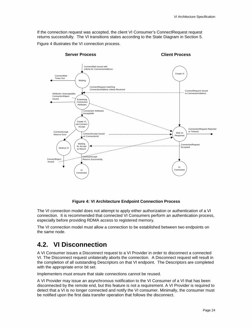
VI Architecture Specification
Page 24
If the connection request was accepted, the client VI Consumer’s ConnectRequest requestreturns successfully. The VI transitions states according to the State Diagram in Section 5.
Figure 4 illustrates the VI connection process.
Figure 4: VI Architecture Endpoint Connection Process
The VI connection model does not attempt to apply either authorization or authentication of a VIconnection. It is recommended that connected VI Consumers perform an authentication process,especially before providing RDMA access to registered memory.
The VI connection model must allow a connection to be established between two endpoints onthe same node.
4.2. VI DisconnectionA VI Consumer issues a Disconnect request to a VI Provider in order to disconnect a connectedVI. The Disconnect request unilaterally aborts the connection. A Disconnect request will result inthe completion of all outstanding Descriptors on that VI endpoint. The Descriptors are completedwith the appropriate error bit set.
Implementers must ensure that stale connections cannot be reused.
A VI Provider may issue an asynchronous notification to the VI Consumer of a VI that has beendisconnected by the remote end, but this feature is not a requirement. A VI Provider is required todetect that a VI is no longer connected and notify the VI consumer. Minimally, the consumer mustbe notified upon the first data transfer operation that follows the disconnect.
Server Process Client Process
Waiting
ConnectWait issued with criteria for ConnectionAddress
ConnectRequest matching ConnectionAddress criteria Received
Attributes Unacceptable,ConnectionRejectIssued
ConnectWaitTimes Out
ConnectRequest Issued to ConnectionAddress
Connection AttributesAcceptable
ConnectionRequest Rejectedor Timeout
ConnectionRequestAccepted
ExaminingConnectionAttributes
Create VI,call Connect-
Accept
Create VI
VI Connected
Waitingfor Acceptto Return
ConnectAccept Issued on ConnectionId
ConnectAcceptReturns Error
ConnectAcceptReturns Successfully
Destroy VI
ConnectReject Issued
Wait onResponse
VIConnected
VI Architecture Specification
Page 25
When a VI Consumer issues a Disconnect request for a VI, the VI will transition to a new stateaccording to the change of state rules listed in Section 5.
4.3. VI Address FormatEach VI Provider must define an address format that uniquely identifies all possible VIs on aSAN. A VI Consumer must be aware of the address format used by a VI Provider. The addressformat must allow VI discrimination across systems as well as on the same node. The formatmust also permit discrimination of connection requests from only a specific VI or from any VI. TheVI Address Format does not require support for multicast or broadcast capability.

VI Architecture Specification
Page 26
5. VI StatesA VI may be in one of four states throughout its life. The four states are Idle, Pending Connect,Connected, and Error. Transitions between states are driven by requests issued by the VIConsumer and network events. Requests that are not valid while a VI is in a given state, such assubmitting a connect request while in the Pending Connect state, must be returned with an errorby the VI Provider.
Figure 5 depicts the VI states and the transitions between them.
Figure 5: VI State Diagram
5.1. Idle StateA VI is in the Idle state when it is created. A VI can only be destroyed when in this state. Theremust be no Descriptors on the VI’s Work Queues in order to destroy it.
Submitting a ConnectRequest request to the VI Provider will transition the VI to the PendingConnect state. If the connection request does not complete within the timeout period specified,the VI will return to the Idle state.
When a ConnectAccept request is made, the VI transitions into the Pending Connect state. If therequest fails or times out, the VI returns to the Idle state.
Descriptors may be posted to the Receive Queue for a VI while the VI is in the Idle state, but theDescriptors will not be processed until the VI transitions to the Connected state or the VIConsumer issues a Disconnect request.
Descriptors posted to the Send Queue of an Idle VI are immediately completed in error.
Create VI
Idle PendingConnect
ConnectedError
Destroy VI
ConnectRequest or ConnectAccept called
ConnectRequest Timeout or ConnectRejector Disconnect
Disconnect
ConnectRequest accepted orConnectAccept Returns
ConnectRequest Erro
r
VI Error
Disconnect
VI Architecture Specification
Page 27
Errors that occur while a VI is in the Idle state, which would normally result in the invocation of theasynchronous error handling mechanism, are reported when the VI Consumer attempts toconnect the VI.
5.2. Pending Connect StateThe Pending Connect state indicates that a connection request has been submitted to the VIProvider but that the connection has not yet been established.
This state is entered when a ConnectRequest operation is submitted to the VI Provider while theVI is in the Idle state.
This state is entered when a ConnectAccept operation has been submitted to the VI Provider fora VI in the Idle state. The VI stays in this state until the connection acceptance processing hascompleted.
A confirmed and successful response to a ConnectRequest request will transition the VI into theConnected state.
A successful ConnectAccept request will transition the VI into the Connected state.
A timeout or rejection of the Connect request transitions the VI into the Idle state.
A Disconnect request issued for a VI in the Pending Connect state results in the VI transitioninginto the Idle state.
Transport or hardware errors generated from the VI NIC will transition the VI into the Error state.
Descriptors may be posted to the Receive Queue of a VI in the Pending Connect state, but theywill not be processed until the VI transitions to the Connected state or the VI Consumer issues aDisconnect request.
Descriptors posted to the Send Queue of a VI in the Pending Connect state are completed inerror.
There cannot be any inbound or outbound traffic on a VI in this state, because the VI is notconnected.
5.3. Connected StateThe Connected state is the state of normal processing. This is the state in which data flowsacross the connection.
A VI transitions into this state from the Pending Connect state upon a confirmed and successfulresponse to a ConnectRequest request.
A VI transitions into this state from the Pending Connect state upon successful completion of aConnectAccept request.
A Disconnect request submitted to the VI Provider by the local VI Consumer transitions a VI tothe Idle state.
Hardware errors will result in the VI transitioning into the Error state. Other errors that occur mayalso result in the VI transitioning into the Error state. This behavior is dependent upon thereliability level of the connection, as discussed in Section 2.5.
Descriptors posted to the Send or Receive Queue of a VI in the Connected state are processednormally.
All inbound and outbound traffic is processed normally.

VI Architecture Specification
Page 28
5.4. Error StateThe Error state is entered as the result of an error during normal processing, or an eventgenerated by the VI NIC.
For VIs with Reliable Delivery or Reliable Reception guarantees, certain classes of errors thatoccur while the VI is in the Connected state will result in transitions into the Error state. This isdiscussed in Section 2.5.
A Disconnect request will transition the VI into the Idle state. Descriptors pending or posted toeither the Receive Queue or the Send Queue when the VI is in this state will result in theDescriptor being completed in error.
Inbound traffic sent to this VI is refused. There is no outbound traffic, since requests posted tothe Send Queue are completed in error. Any outbound traffic left on a queue when the VItransitions into this state is aborted and the corresponding Descriptors are completed in error.

VI Architecture Specification
Page 29
6. Descriptor Processing ModelData transfer requests are represented by Descriptors. Descriptors contain all the informationneeded to process a request, such as the type of transfer to make, the status of the transfer,queue information, immediate data and a scatter-gather style buffer pointer list.
Figure 6 illustrates the VI Architecture Descriptor processing models, namely the Work QueueModel and the Completion Queue Model. They differ only in how the VI Consumer is notified ofDescriptor completion. In both cases, Descriptors are enqueued and dequeued from a VI’s WorkQueue. In the Work Queue Model, the VI Consumer polls for completions on a particular WorkQueue by examining the status of the Descriptor at the head of the queue. When the headDescriptor is completed, the VI Consumer dequeues it. In the Completion Queue Model, the VIConsumer polls for completions on a set of Work Queues by examining the head of theCompletion Queue. When a Descriptor completes, its identity is written to the Completion Queue.Once the VI Consumer receives notification of a Descriptor completion from the CompletionQueue, the VI Consumer must dequeue the Descriptor from the appropriate Work Queue. A VIProvider should supply a mechanism by which VI Consumers can wait for Descriptors tocomplete on a VI Work Queue or wait for a notification to be posted to a Completion Queue.
Figure 6: VI Architecture Descriptor Processing Models
6.1. Forming DescriptorsThere are two types of Descriptors, each one serving two different functions. There areSend/Receive type Descriptors and there are RDMA type Descriptors. The two functions areoutbound data transfer and inbound data transfer.
A Descriptor occupies a variable-length, virtually contiguous region of a process’s virtual addressspace. Descriptors must be aligned on a 64-byte boundary. Descriptors must reside in memoryregions that have been registered by the VI Consumer with the VI Provider. Descriptors maycross physical page boundaries, as long as a single Descriptor resides within a single memoryregion. Any time a Descriptor is used in a request to the VI Provider, it must be accompanied bythe memory handle associated with the region of memory where the Descriptor lies.
Descriptor allocation is managed by the VI Consumer.
Posting a Descriptor to a VI Work Queue transfers ownership of the Descriptor to the VI Provider.Modification of a Descriptor by the VI Consumer while it is posted results in unpredictablebehavior. Ownership of the Descriptor is returned to the VI Consumer when the VI Provider

VI Architecture Specification
Page 30
completes the Descriptor. A VI Provider completes a Descriptor by writing a completion statusvalue into the Descriptor. The VI Provider must also write an entry to the associated CompletionQueue, if one is in use.
Descriptors are composed of segments. There are three types of segments: control, address anddata. Descriptors always begin with a Control Segment. The Control Segment contains controland status information as well as reserved fields that are used for queuing.
An Address Segment follows the Control Segment, but only for RDMA operations. This segmentcontains remote buffer information for RDMA Read and RDMA Write operations.
The Data Segment contains information about the local buffers of a send, receive or RDMA Reador RDMA Write operation. A Descriptor may contain multiple Data Segments.
6.1.1. Data Considerations
6.1.1.1. Scatter-Gather ConsiderationsThe Descriptor format allows the VI Consumer to specify a scatter-gather list in each Descriptorso that data can be sent from or placed in the desired location(s) directly by the hardware. The VIConsumer may construct a scatter-gather list of any length up to and including the NIC’s segmentcount limit. The Scatter-Gather List length can be zero so that a data transfer of only ImmediateData, or even no data, can take place. Zero length Scatter-Gather elements are also acceptable.The VI NIC must support a minimum segment count limit of at least 252 Data Segments.
6.1.1.2. Size ConsiderationsData transfers can be of any length, not exceeding the Maximum Transmission Unit (MTU) of anyVI Provider. The sum of the lengths of the Scatter-gather elements is the total data length.
The minimum allowable MTU is 32KB. This guarantees the VI Consumer that any VI Providercan transmit at least 32KB in a single Descriptor. Some vendors may choose to support an MTUlarger than 32KB. Each VI Provider should supply a mechanism by which a VI Consumer candetermine the MTU supported by the Provider.
6.2. Posting DescriptorsOnce a Descriptor has been prepared, the VI Consumer submits it to the VI NIC for processing byposting it to the appropriate VI Work Queue and ringing the queue’s Doorbell. The format andoperation of the Doorbell is specific to each VI Provider.
Send and Receive requests are posted to their respective Work Queues. Remote DMA requests,both Write and Read, are always posted to the Send Queue.
Receive Descriptors may be posted before a connection is established, but they will notcomplete, except in error cases, until the VI is connected and data is received. Pre-postingDescriptors can prevent error conditions, specifically data being dropped or rejected due to lackof receive Descriptors.
Send and RDMA Descriptors that are submitted to a VI before a connection is established will becompleted in error. They cannot be processed until the receiving endpoint is defined, and thusare considered an error.
Posting a Descriptor does not block the processing of already posted Descriptors.
6.3. Processing DescriptorsOnce a Descriptor has been posted to a queue, the VI NIC can begin processing it.
Data is transferred between two connected VIs when a VI NIC processes a Descriptor or as thedata arrives on the network. Immediate data is transferred at this time as well.

VI Architecture Specification
Page 31
If an error is encountered during processing of the Descriptor, the VI NIC is expected to take theappropriate action, according to the type of error encountered and the reliability level of theConnection.
6.3.1. Ordering Rules and BarriersThe order of processing of Descriptors posted to the VI Work Queues must be consistent acrossall VI Architecture implementations. These rules apply to the processing on a single queue.Ordering across multiple Work Queues is undefined, but is expected to provide fairness.
6.3.1.1. Ordering RulesReceive and Send queues are FIFO queues. Descriptors are enqueued and dequeued in order.The VI Provider does not reorder queues.
Receive queues are strict FIFO queues. Once enqueued, Descriptors are processed, completed,and dequeued in FIFO order.
Send queues are FIFO queues. Once enqueued, Descriptors begin processing in order, but maycomplete out of order. Descriptors are always dequeued in FIFO order regardless of completionorder. Send and RDMA Write Descriptors are completed in strict FIFO order. RDMA ReadDescriptors may complete out of order with respect to Send and RDMA Write Descriptors. RDMAReads complete in FIFO order with respect to one another.
Unlike Sends and RDMA Writes, RDMA Reads require a round trip path. For performancereasons, it is not optimal to specify that Descriptor processing is stopped on a given queue whenan RDMA Read is issued until after the data are returned. This would make queue processing onReliable Delivery connections dependent on remote node processing capability. Therefore,Sends and RDMA Writes may begin processing before RDMA Reads have completed.
A Send that bypasses an RDMA Read may write data into the receiving memory regions at anytime prior to the completion of the RDMA Read. The contents of the pended receive buffermemory are unpredictable until the associated remote Receive queue Descriptor is completedsuccessfully. On a Reliable Delivery connection, the bypassing Send may consume a remoteReceive queue Descriptor and be completed successfully prior to the completion of the RDMARead. The remote VI Consumer may receive the bypassing Send successfully prior to thecompletion of the RDMA Read and/or in the event of an error on the RDMA Read. On a ReliableReception connection, the receiving VI Provider must not successfully complete the bypassingSend until after all RDMA Read data have been transmitted without error. In the event of an erroron the RDMA Read, no remote Receive queue Descriptor is consumed.
An RDMA Write that bypasses an RDMA Read may write data into the remote memory regiononly on a Reliable Delivery connection. In the event of an error on the RDMA Read, thebypassing RDMA Write may have completed successfully and have side effects. It is theresponsibility of the issuing VI Consumer to dequeue all commands and take appropriate action.No such side effects are permitted on a Reliable Reception connection. The remote VI Providermust not modify the contents of the remote memory region or, in the case of immediate data,consume a Receive queue Descriptor until after the RDMA Read has completed. In the event ofan error on the RDMA Read, the RDMA Write must have no remote effect.
Sends and RDMA Writes always complete in the order in which they are queued.
• Sends do not pass sends
• Sends do not pass RDMA Writes
• RDMA Writes do not pass sends
• RDMA Writes do not pass RDMA Writes
VI Architecture Specification
Page 32
RDMA Reads do not necessarily complete before Sends or RDMA Writes queued after thembegin processing.
• RDMA Reads do not pass sends
• RDMA Reads do not pass RDMA Writes
• RDMA Reads do not pass RDMA Reads
• Sends can pass RDMA Reads
• RDMA Writes can pass RDMA Reads
If strict order is required, the VI Consumer will have to use a processing barrier. This would betrue in the case of a VI Consumer using a Reliable Delivery connection desiring that a Sendfollowing an RDMA Read notify the connecting VI Consumer that the buffer is now free to reuse.
The above rules provide ordering guarantees to VI consumers. VI implementers are permitted toimplement more strict ordering rules than those exposed above.
6.3.1.2. BarriersBarriers are a way to indicate to the VI NIC that all Descriptors before the designated Descriptormust complete before processing can continue.
By setting the Queue Fence bit in a Descriptor, the VI Consumer can ensure that all Descriptorsposted on the Send Queue before that Descriptor have completed before processing begins onthat Descriptor. This provides the VI Consumer with a synchronization mechanism to guaranteethe contents of registered memory.
6.3.2. Address Translation and Memory AccessA VI NIC uses its Page Tables, combined with Memory Handles and Virtual Addresses in order toperform address translation. This information is combined with the Memory Protection Tag toensure not only that the address is valid, but that the memory access is permitted by this VIand/or by incoming RDMA requests. All addresses of RDMA requests must be validatedaccording to the incoming Handle and Virtual Address as well as the Memory Protection Tag andMemory Protection Attributes associated with the Handle and the VI before data transfer can takeplace.
6.4. Completing DescriptorsWhen data transfer has completed, the Descriptor must be completed. This is achieved in twophases. In the first phase, the VI Provider updates the Control Segment contents and, if thequeue is linked to a Completion Queue, an entry is generated in the Completion Queue. In thesecond phase, the VI Consumer dequeues the Descriptor.
6.4.1. Completing Descriptors by the VI ProviderWhen the VI NIC has completed processing a Descriptor, it must update the information in theControl Segment of the Descriptor with completion codes, length fields and possibly immediatedata.
When the completion indicator is set in the Descriptor, the VI NIC is signaling that it has finishedupdating all information in the Descriptor and the Descriptor has been removed from the VI NIC’sinternal processing queues. Note that the Status must be the last item updated to ensure that theDescriptor is not pulled prematurely. The Done bit in the Status is used for synchronization.
If a Completion Queue has been registered for the queue that this Descriptor is on, the VI NIC willplace an entry on the Completion Queue that indicates the completed Descriptor’s VI and queue.

VI Architecture Specification
Page 33
The VI Consumer is responsible for ensuring that a Completion Queue is large enough to hold aCompletion Queue entry for each Descriptor that may complete at any given time. The VIProvider is not required to report an error if the Completion Queue Overruns. If a CompletionQueue overruns, completion entries will be lost.
If a data transfer incurs a data overrun error, the Receive Descriptor’s total length is set to zero,the data is undefined and may result in the VI transitioning into the Error state as per thediscussions in Sections 2.5 and 5. The Receive Descriptor is marked in error with a length error.
If an error occurred, the Descriptor is marked with the appropriate error status and the VI willtransition to a new state according to the discussions in Sections 2.5 and 5.
6.4.1.1. Kernel Agent InteractionsThe Kernel Agent is invoked during normal processing only if the VI NIC generates an interrupt.The VI NIC always generates an interrupt on asynchronous errors. An interrupt is also generatedwhen a VI Consumer thread is blocked in the VI Provider, waiting for a Descriptor at the head of aqueue to complete.
If the VI Queue or Completion Queue is enabled for interrupts and the VI NIC has completedprocessing a Descriptor for that VI Queue or Completion Queue, then the VI NIC will generate aninterrupt. This action allows the Kernel Agent to unblock any VI Consumer threads waiting forcompletions.
If the interrupt is due to an error that is valid for the reliability level of this VI, an asynchronouserror handling mechanism is invoked to deliver the error to the VI Consumer.
6.4.2. Completing Descriptors by the VI ConsumerThe VI Consumer may synchronize on completed Descriptors in the following ways:
• Poll a VI Work Queue
• Wait on a VI Work Queue
• Poll a Completion Queue
• Wait on a Completion Queue
A VI Consumer polls on a Work Queue by reading the Status field of the Descriptor at the head ofthe queue. When the Done bit is set, the Consumer may dequeue the Descriptor. A VI Consumerpolls on a Completion Queue by examining the head of the Queue. When a Descriptor iscompleted, information describing it will be written to the Completion Queue. The VI Consumeruses this information to find the appropriate Work Queue and dequeue the head Descriptor.
A VI Consumer can wait for completions on a Work Queue or a Completion Queue through amechanism supplied by the Kernel Agent. This mechanism involves informing the NIC that aninterrupt should be generated for the next completion on the specified Work Queue or CompletionQueue. The Kernel Agent fields this interrupt and unblocks the appropriate thread. The threadthen processes the completion as if it had polled for it.
VI Architecture Specification
Page 34
7. Error HandlingMost errors are reported synchronously to the VI Consumer, either at a time an operation isattempted, or when a Descriptor completes. Some errors can not be reported synchronously.
Asynchronous errors include those that cause queue processing to hang, those that occur after aDescriptor has been completed, and errors requiring immediate intervention such as a networkcable disconnection. A VI Provider should supply a mechanism by which asynchronous errorsmay be delivered to a VI Consumer. Some errors may also be logged according to standardoperating system conventions.
The asynchronous errors reported by a VI Provider vary according to the reliability level of theconnection, as defined in the following sections. Certain types of errors will be reportedasynchronously regardless of the reliability level of the connection. These include hardware-related issues that require immediate notification.
7.1. Error Handling for Unreliable ConnectionsThe asynchronous error handling mechanism for Unreliable Connections is only invoked in thecase of a catastrophic hardware error. This includes queue hangs, VI NIC errors, or link loss.
This class of connection assumes that the VI Consumer will implement any appropriate protocollogic deemed necessary to ensure packet arrival, so no attempt is made to determine transportlevel issues or to report them to the VI Consumer.
7.2. Error Handling for Reliable Delivery ConnectionsThe asynchronous error handling mechanism for Reliable Delivery Connections is invoked in thecase of catastrophic transport or hardware errors. This includes queue hangs, VI NIC errors orlink loss, and catastrophic transport oriented errors such as dropped or missed packets.
Upon any error, the Connection is placed into the Error state and will behave according to therules discussed in Section 5.4. The error handling mechanism is also invoked. The VI Consumershould attempt to clean up and take whatever action it deems necessary, according to theconditions of the error.
For Reliable Delivery VIs, the asynchronous error handling mechanism will be invoked fortransport errors after one or more posted Descriptors packets have been completed by the VINIC.
7.3. Error Handling for Reliable Reception ConnectionsThe asynchronous error handling mechanism for Reliable Reception Connections is invoked inthe case of catastrophic transport or hardware errors. This includes queue hangs, VI NIC errorsor link loss, and transport oriented errors such as dropped or missed packets.
Upon any error, the Connection is placed into the Error state and will behave according to therules discussed in Section 5.4. The error handling mechanism is also invoked. The VI Consumershould attempt to clean up and take whatever action it deemed necessary, according to theconditions of the error.
For Reliable Reception Connection, the asynchronous error handling mechanism will be invokedfor transport errors after no more than one, and possibly zero, posted Descriptors have beencompleted by the VI NIC.
VI Architecture Specification
Page 35
8. GuidelinesVI Consumers should be aware of the trade-offs in time and resources when using the VIArchitecture. The VI Architecture optimizes only the data transfer path. Some VI Provideroperations are inherently more time consuming than data transfers. These operations are:
• Buffer Registration requires a kernel transition, locking down of the physical pages in memoryand manipulation of the VI NIC page tables. De-registration is also time consuming. It isrecommended that memory regions are registered infrequently by the VI Consumer and thatspace within the memory region is judiciously managed.
• Creation of a VI requires a kernel transition, allocation of resources in the kernel and in the VINIC, and interaction with the VI NIC so that a Doorbell can be created and mapped into theVI Consumer’s address space.
• Connection of a VI to another VI implies execution of a protocol between endpoints andconsists of several operations by the VI Consumer and VI Provider.
• Transfer of data that is poorly aligned could result in longer transfer times.
Resources available on any given VI NIC are finite.
• The number of VIs that a VI NIC supports is finite.
• There may be side effects in over-using the registration/de-registration process such asfragmentation of the VI NIC’s page tables.
• Registered memory consumes non-pageable memory on the host node.
• The number of Completion Queues that a VI NIC supports is finite.
• A VI Consumer will have to perform segmentation and reassembly to transfer data largerthan the MTU supported by the VI Provider.
8.1. ScalabilityVI Architecture implementers should be especially concerned with scalability considerations. Theinterconnect mechanisms, which include the VI NIC, the physical media and any switch orconnection facilitator, need to scale with the number of instances of the application as well as thenumber of applications running within a node. The throughput of the network must scale as well.Fairness and scalability must be ensured at all levels to adequately grow the number of activeconnections.
A usage model of (1+M)(N-1) VIs per node is suggested as a minimum number of VIs supportedby an implementation, where N is the number of nodes in a cluster and M is the number ofdistinct processes consuming VIs on each node. This allows for one VI in kernel mode, and foreach application to consume one VI to establish a connection to every other node in the cluster.
A sample usage of this formula is a 16 node cluster with three distributed applications runningacross all nodes. This would result in (1+3)(16-1) or 100 VIs open in a given machine. This is therecommended minimum number of VIs that a VI NIC should consider supporting, with 1024 VIsbeing a more reasonable number to allow for growth and application flexibility.

VI Architecture Specification
Page 36
9. Appendix A
9.1. Example VI User Agent OverviewThis section describes an example functional interface to the VI Architecture. It is meant as anaid to hardware implementers, to illustrate a reasonably complete software embodiment of the VIArchitecture. The material is presented in the form of groups of related routines, followed bydefinitions of data structures, constants and error codes.
9.2. Hardware Connection
9.2.1. VipOpenNic
Synopsis
VIP_RETURNVipOpenNic(
IN const VIP_CHAR *DeviceName,OUT VIP_NIC_HANDLE *NicHandle
)
Parameters
DeviceName: Symbolic name of the device (VI Provider instance) associated with the NIC.
NicHandle: Handle returned. The handle is used with the other functions to specify aparticular instance of a VI NIC.
Description
VipOpenNic associates a process with a VI NIC, and provides a NIC handle to the VI Consumer.The NIC handle is used in subsequent functions in order to specify a particular NIC.
Returns
VIP_SUCCESS – Operation completed successfully.
VIP_ERROR_RESOURCE – An error was detected due to insufficient resources.
VIP_INVALID_PARAMETER – One of the parameters were invalid.
9.2.2. VipCloseNic
Synopsis
VIP_RETURNVipCloseNic(
IN VIP_NIC_HANDLE NicHandle)
Parameters
NicHandle: The NIC handle.

VI Architecture Specification
Page 37
Description
VipCloseNic removes the association between the calling process and the VI NIC that wasestablished via the corresponding VipOpenNic function.
Returns
VIP_SUCCESS – Operation completed successfully.
VIP_INVALID_PARAMETER – Caller specified an invalid NIC handle.
9.3. Endpoint Creation and Destruction
9.3.1. VipCreateVi
Synopsis
VIP_RETURNVipCreateVi(
IN VIP_NIC_HANDLE NicHandle,IN VIP_VI_ATTRIBUTES *ViAttribs,IN VIP_CQ_HANDLE SendCQHandle,IN VIP_CQ_HANDLE RecvCQHandle,OUT VIP_VI_HANDLE *ViHandle
)
Parameters
NicHandle: Handle of the associated VI NIC.
ViAttribs: The initial attributes to set for the new VI.
SendCQHandle: The handle of a Completion Queue. If a valid handle, the send Work Queue ofthis VI will be associated with the Completion Queue. If NULL, the send queue isnot associated with any Completion Queue.
RecvCQHandle: The handle of a Completion Queue. If valid, the receive Work Queue of this VIwill be associated with the Completion Queue. If NULL, the receive queue is notassociated with any Completion Queue.
ViHandle: The handle for the newly created VI instance.
Description
VipCreateVi creates an instance of a Virtual Interface to the specified NIC.
The Attributes input parameter specifies the initial attributes for this VI instance.
The SendCQHandle and RecvCQHandle parameters allow the caller to associate the WorkQueues of this VI with a Completion Queue. If one or both of the Work Queues are associatedwith a Completion Queue, the calling process cannot wait on that queue via VipSendWait orVipRecvWait.
When a new instance of a VI is created, it begins in the Idle state.
Returns
VIP_SUCCESS – Operation completed successfully.

VI Architecture Specification
Page 38
VIP_ERROR_RESOURCE – Insufficient resources.
VIP_INVALID_PARAMETER – One of the input parameters was invalid.
VIP_INVALID_RELIABILITY_LEVEL – The requested reliability level attribute was invalid or notsupported.
VIP_INVALID_MTU – The maximum transfer size attribute was invalid or not supported.
VIP_INVALID_QOS – The quality of service attribute was invalid or not supported.
VIP_INVALID_PTAG – The protection tag attribute was invalid.
VIP_INVALID_RDMAREAD – The attributes requested support for RDMA Read, but the VIProvider does not support it.
9.3.2. VipDestroyVi
Synopsis
VIP_RETURNVipDestroyVi(
IN VIP_VI_HANDLE ViHandle)
Parameters
ViHandle: The handle of the VI instance to be destroyed.
Description
VipDestroyVi tears down a Virtual Interface. A VI instance may only be destroyed if the VI is inthe Idle state and all Descriptors on its work queues have been de-queued, otherwise an error isreturned to the caller. Use of the destroyed handle in any subsequent operation will fail.
Returns
VIP_SUCCESS – Operation completed successfully
VIP_INVALID_PARAMETER – An invalid VI Handle was specified.
VIP_ERROR_RESOURCE – The VI was not in the Idle state or there are still Descriptors postedon the work queues.
VI Architecture Specification
Page 39
9.4. Connection Management
9.4.1. VipConnectWait
Synopsis
VIP_RETURNVipConnectWait(
IN VIP_NIC_HANDLE NicHandle,IN VIP_NET_ADDRESS *LocalAddr,IN VIP_ULONG Timeout,OUT VIP_NET_ADDRESS *RemoteAddr,OUT VIP_VI_ATTRIBUTES *RemoteViAttribs,OUT VIP_CONN_HANDLE *ConnHandle
)
Parameters
NicHandle: Handle for an instance of a VI NIC.
LocalAddr: Local network address on which to wait.
Timeout: The count, in milliseconds, that VipConnectWait will wait to complete beforereturning to the caller. VIP_INFINITE if no time-out is desired. A timeout of zeroindicates immediate return.
RemoteAddr: The remote network address that is requesting a connection.
ConnHandle: A handle to an opaque connection object subsequently used in calls toVipConnectAccept and VipConnectReject.
RemoteViAttribs: The attributes of the remote VI endpoint that is requesting the connection.
Description
VipConnectWait is used to look for incoming connection requests.
The caller passes in a local network address that is used to filter incoming connection requests.The format of the network address is VI Provider specific.
If a matching connection request is not found immediately, VipConnectWait will wait for a requestuntil the Timeout period has expired.
If a connection request is found that matches the LocalAddress, the caller is returned the remoteaddress that is requesting a connection, the attributes of the remote endpoint that is requestingthe connection, and a connection handle to be used in subsequent calls to VipConnectAccept orVipConnectReject.
Returns
VIP_SUCCESS – The operation has successfully found a connection request.
VIP_TIMEOUT – The operation timed out, no connection request was found.
VIP_ERROR_RESOURCE – The connection operation failed due to a resource limit.
VIP_INVALID_PARAMETER – One of the parameters was invalid.
VI Architecture Specification
Page 40
9.4.2. VipConnectAccept
Synopsis
VIP_RETURNVipConnectAccept(
IN VIP_CONN_HANDLE ConnHandle,IN VIP_VI_HANDLE ViHandle
)
Parameters
ConnHandle: A handle to an opaque connection object created by VipConnectWait.
ViHandle: Instance of a local VI endpoint.
Description
VipConnectAccept is used to accept a connection request and associate the connection with alocal VI endpoint.
The caller passes in the handle of an Idle, unconnected VI endpoint to associate with theconnection request. If the attributes of the local VI endpoint conflict with those of the remoteendpoint, VipConnectAccept will fail. It is the function of the VI Provider to determine if theconnection should succeed based on the attributes of the two endpoints.
If VipConnectAccept fails, no explicit notification is sent to the remote end. The caller maychoose to modify the attributes of the local VI endpoint, and try again. In order to reject aconnection request, the VI Consumer must explicitly reject the connection request via theVipConnectReject function.
Returns
VIP_SUCCESS – The connection was successfully established.
VIP_INVALID_PARAMETER – One of the parameters was invalid.
VIP_INVALID_ RELIABILITY_LEVEL – The reliability level attribute of the local endpointconflicted with the reliability level of the remote VI.
VIP_INVALID_MTU – The maximum transfer size attribute of the local endpoint conflicted withthe maximum transfer size of the remote endpoint.
VIP_INVALID_QOS – The quality of service attribute was invalid, or conflicted with the remoteendpoint.
9.4.3. VipConnectReject
Synopsis
VIP_RETURNVipConnectReject(
IN VIP_CONN_HANDLE ConnHandle)
Parameters
ConnHandle: A handle to an opaque connection object created by VipConnectWait.

VI Architecture Specification
Page 41
Description
VipConnectReject is used to reject a connection request. Notification is sent to the remote endthat the associated connection request was rejected.
Returns
VIP_SUCCESS – The operation completed successfully.
VIP_INVALID_PARAMETER – The ConnHandle parameter was invalid.
9.4.4. VipConnectRequest
Synopsis
VIP_RETURNVipConnectRequest(
IN VIP_VI_HANDLE ViHandle,IN VIP_NET_ADDRESS *LocalAddr,IN VIP_NET_ADDRESS *RemoteAddr,IN VIP_ULONG Timeout,OUT VIP_VI_ATTRIBUTES *RemoteViAttribs
)
Parameters
ViHandle: Handle for the local VI endpoint.
LocalAddr: Local network address.
RemoteAddr: The remote network address.
Timeout: The count, in milliseconds, that VipConnectRequest will wait for connection tocomplete before returning to the caller, VIP_INFINITE if no time-out is desired. Atimeout value of zero is invalid.
RemoteViAttribs: The attributes of the remote endpoint if successful.
Description
VipConnectRequest requests that a connection be established between the local VI endpoint,and a remote endpoint. The user specifies a local and remote network address for theconnection.
If a connection is successfully established, the specified local address is bound to the local VIendpoint, and the attributes of the remote endpoint are returned to the caller. The attributes ofthe remote endpoint allow the caller to determine whether the indicated RDMA operations can beexecuted on the resulting connection.
If the remote end rejects the connection, a rejection error is returned. If a connection cannot beestablished before the specified Timeout period, a timeout error is returned. Specifying a timeoutvalue of zero is invalid and will result in an immediate timeout error.
Returns
VIP_SUCCESS – The connection was successfully established.
VIP_TIMEOUT – The connection operation timed out.

VI Architecture Specification
Page 42
VIP_ERROR_RESOURCE – The connection operation failed due to a resource limit.
VIP_INVALID_PARAMETER – One of the parameters was invalid.
VIP_REJECTED – The connection was rejected by the remote end.
9.4.5. VipDisconnect
Synopsis
VIP_RETURNVipDisconnect(
IN VIP_VI_HANDLE ViHandle)
Parameters
ViHandle: Instance of a connected Virtual Interface endpoint.
Description
VipDisconnect is used to terminate a connection. When the local endpoint is disconnected, itstops processing of all posted Descriptors, all posted Descriptors are marked completed becauseof disconnection, and the local endpoint transitions to the Idle state.
Returns
VIP_SUCCESS – The disconnect was successful.
VIP_INVALID_PARAMETER – The ViHandle parameter was invalid.
9.5. Memory protection and registration
9.5.1. VipCreatePtag
Synopsis
VIP_RETURNVipCreatePtag(
IN VIP_NIC_HANDLE NicHandle,OUT VIP_PROTECTION_HANDLE *ProtectionTag
)
Parameters
NicHandle: The NIC handle associated with the protection tag.
ProtectionTag: The new protection tag.
Description
The VipCreatePtag function creates a new protection tag for the calling process. The protectiontag is subsequently associated with VI endpoints via the VipCreateVi function, as well as memoryregions via the VipRegisterMem function. A process may request multiple protection tags.

VI Architecture Specification
Page 43
For all memory references by the VI Provider, including Descriptors and message buffers, theprotection tag of the VI instance, and the memory region, must match in order to pass thememory protection check.
The Protection Tag is an element in the VI attributes data structure and the Memory RegionAttributes data structure. The protection tag of a memory region and/or a VI can be changed bychanging their attributes.
Returns
VIP_SUCCESS – The memory protection tag was successfully created.
VIP_ERROR_RESOURCE – The operation failed due to a resource limit.
VIP_INVALID_PARAMETER – One of the parameters was invalid.
9.5.2. VipDestroyPtag
Synopsis
VIP_RETURNVipDestroyPtag(
IN VIP_NIC_HANDLE NicHandle,IN VIP_PROTECTION_HANDLE ProtectionTag
)
Parameters
NicHandle: The NIC handle associated with the protection tag.
ProtectionTag: The protection tag.
Description
The VipDestroyPtag function destroys a protection tag.
If the specified protection tag is associated with either a VI instance or a registered memoryregion at the time of the call, an error is returned.
Returns
VIP_SUCCESS – The memory protection tag was successfully destroyed.
VIP_ERROR_RESOURCE – A VI instance or a registered memory region is still associated withthe specified protection tag.
VIP_INVALID_PARAMETER – One of the input parameters was invalid.

VI Architecture Specification
Page 44
9.5.3. VipRegisterMem
Synopsis
VIP_RETURNVipRegisterMem(
IN VIP_NIC_HANDLE NicHandle,IN VIP_PVOID VirtualAddress,IN VIP_ULONG Length,IN VIP_MEM_ATTRIBUTES *MemAttribs,OUT VIP_MEM_HANDLE *MemoryHandle
)
Parameters
NicHandle: Handle for a currently open NIC.
VirtualAddress: Starting address of the memory region to be registered.
Length: The length, in bytes, of the memory region.
MemAttribs: The memory attributes to associate with the memory region.
MemoryHandle: If successful, the new memory handle for the region, otherwise NULL.
Description
VipRegisterMem allows a process to register a region of memory with a VI NIC. Memory used tohold Descriptors or data buffers must be registered with this function.
The user may specify an arbitrary size region of memory, with arbitrary alignment, but the actualarea of memory registered will be registered on page granularity. Registered pages are lockedinto physical memory.
The memory attributes include the Protection Tag, and the RDMA enable bits that are initiallyassociated with the memory region.
Descriptors and data buffers contained within registered memory can be used by any VI with amatching protection tag that is owned by the process. A new memory handle is generated foreach region of memory that is registered by a process.
The EnableRdmaWrite memory attribute can be used to ensure that no remote process canmodify a region of memory, this could be particularly useful to protect regions of memory thatcontain Descriptors (control information). The EnableRdmaRead parameter can be used toensure that no remote process can read a particular region of memory.
Note that the implementation of VipRegisterMem should always check for read-only pages ofmemory and not allow modification to those pages by the VI Hardware.
A Length parameter of zero will result in a VIP_INVALID_PARAMETER error.
The contents of the memory region being registered are not altered. The memory region musthave been previously allocated by the VI Consumer.
Returns
VIP_SUCCESS – The memory region was successfully registered.
VIP_ERROR_RESOURCE – The registration operation failed due to a resource limit.
VIP_INVALID_PARAMETER – One of the parameters was invalid.
VIP_INVALID_PTAG – The protection tag attribute was invalid.

VI Architecture Specification
Page 45
VIP_INVALID_RDMAREAD – the attributes requested the memory region be enabled for RDMARead, but the VI Provider does not support it.
9.5.4. VipDeregisterMem
Synopsis
VIP_RETURNVipDeregisterMem(
IN VIP_NIC_HANDLE NicHandle,IN VIP_PVOID VirtualAddress,IN VIP_MEM_HANDLE MemoryHandle
)
Parameters
NicHandle: The handle for the NIC that owns the memory region being de-registered.
VirtualAddress: Address of the region of memory to be de-registered.
MemoryHandle: Memory handle for the region; obtained from a previous call to VipRegisterMem.
Description
VipDeregisterMem de-registers memory that was previously registered using theVipRegisterMem function and unlocks the associated pages from physical memory. The contentsand attributes of region of virtual memory being de-registered are not altered in any way.
Returns
VIP_SUCCESS – The memory region was successfully de-registered.
VIP_INVALID_PARAMETER – One or more of the parameters was invalid.
9.6. Data transfer and completion operations
9.6.1. VipPostSend
Synopsis
VIP_RETURNVipPostSend(
IN VIP_VI_HANDLE ViHandle,IN VIP_DESCRIPTOR *DescriptorPtr,IN VIP_MEM_HANDLE MemoryHandle
)
Parameters
ViHandle: Instance of a Virtual Interface.
DescriptorPtr: Pointer to a Descriptor to be posted on the send queue.
MemoryHandle: The handle for the memory region of the Descriptor being posted.
VI Architecture Specification
Page 46
Description
VipPostSend adds a Descriptor to the tail of the send queue of a VI, notifies the NIC that a newDescriptor is available, and returns immediately.
Returns
VIP_SUCCESS – The send Descriptor was successfully posted.
VIP_INVALID_PARAMETER – The VI handle was invalid.
9.6.2. VipSendDone
Synopsis
VIP_RETURNVipSendDone(
IN VIP_VI_HANDLE ViHandle,OUT VIP_DESCRIPTOR **DescriptorPtr
)
Parameters
ViHandle: Instance of a Virtual Interface.
DescriptorPtr: Address of the Descriptor that has completed, if any.
Description
VipSendDone checks the Descriptor at the head of the send queue to see if it has been markedcomplete. If the operation has completed, the Descriptor is removed from the head of the queueand the address of the Descriptor is returned. Otherwise an error is returned, and the contents ofDescriptorPtr are invalid.
Returns
VIP_SUCCESS – A completed Descriptor was returned.
VIP_NOT_DONE – No completed Descriptor was found.
VIP_INVALID_PARAMETER – The VI handle was invalid.
9.6.3. VipSendWait
Synopsis
VIP_RETURNVipSendWait(
IN VIP_VI_HANDLE ViHandle,IN VIP_ULONG TimeOut,OUT VIP_DESCRIPTOR **DescriptorPtr
)

VI Architecture Specification
Page 47
Parameters
ViHandle: Instance of a Virtual Interface.
TimeOut: The count, in milliseconds, before control is returned to the caller, VIP_INFINITEif no time-out is desired.
DescriptorPtr: Address of the Descriptor that has completed.
Description
VipSendWait checks the Descriptor on the head of the send queue to see if it has been markedcomplete. If the send has completed, the Descriptor is removed from the head of the queue andthe address of the Descriptor is immediately returned.
If the Descriptor at the head of the send queue has not been marked complete, VipSendWaitblocks the caller until a Descriptor is completed, or until the specified timeout has expired.
VipSendWait cannot be used to block on a send queue that has been associated with acompletion queue. Refer to VipCQWait for a more complete description.
Returns
VIP_SUCCESS – A completed Descriptor was found on the send queue.
VIP_INVALID_PARAMETER – The VI handle was invalid.
VIP_TIMEOUT – The timeout expired and no completed Descriptor was found.
VIP_ERROR_RESOURCE – This send queue is associated with a completion queue.
9.6.4. VipPostRecv
Synopsis
VIP_RETURNVipPostRecv(
IN VIP_VI_HANDLE ViHandle,IN VIP_DESCRIPTOR *DescriptorPtr,IN VIP_MEM_HANDLE MemoryHandle
)
Parameters
ViHandle: Instance of a Virtual Interface.
DescriptorPtr: Pointer to a Descriptor to be posted on the receive queue.
MemoryHandle: The handle for the memory region of the Descriptor being posted.
Description
VipPostRecv adds a Descriptor to the tail of the receive queue of the specified VI, notifies the NICthat a new Descriptor is available, and returns immediately.
Returns
VIP_SUCCESS – The receive Descriptor was successfully posted.

VI Architecture Specification
Page 48
VIP_INVALID_PARAMETER – The VI handle was invalid.
9.6.5. VipRecvDone
Synopsis
VIP_RETURNVipRecvDone(
IN VIP_VI_HANDLE ViHandle,OUT VIP_DESCRIPTOR **DescriptorPtr
)
Parameters
ViHandle: Instance of a Virtual Interface.
DescriptorPtr: Address of the Descriptor that has completed, if any.
Description
VipRecvDone checks the Descriptor on the head of the receive queue to see if it has beenmarked complete. If the receive has completed, the Descriptor is removed from the head of thequeue and the address of the Descriptor is returned. Otherwise an error is returned and thecontents of DescriptorPtr are invalid.
Returns
VIP_SUCCESS – A completed receive Descriptor was returned.
VIP_NOT_DONE – No completed Descriptor was found.
VIP_INVALID_PARAMETER – The VI handle was invalid.
9.6.6. VipRecvWait
Synopsis
VIP_RETURNVipRecvWait(
IN VIP_VI_HANDLE ViHandle,IN VIP_ULONG Timeout,OUT VIP_DESCRIPTOR **DescriptorPtr
)
Parameters
ViHandle: Instance of a Virtual Interface.
TimeOut: The count, in milliseconds, before control is returned to the caller, VIP_INFINITEif no time-out is desired.
DescriptorPtr: Address of the Descriptor that has completed.
VI Architecture Specification
Page 49
Description
VipRecvWait checks the Descriptor on the head of the receive queue to see if it has been markedcomplete. If the receive has completed, the Descriptor is removed from the head of the queueand the address of the Descriptor is immediately returned.
If the Descriptor at the head of the receive queue has not been marked complete, VipRecvWaitblocks the caller until a Descriptor is completed, or until the specified timeout has expired.
VipRecvWait cannot be used to block on a receive queue that has been associated with acompletion queue. Refer to VipCQWait for a more complete description.
Returns
VIP_SUCCESS – A completed Descriptor was found on the receive queue.
VIP_INVALID_PARAMETER – The VI handle was invalid.
VIP_TIMEOUT – The timeout expired and no completed Descriptor was found.
VIP_ERROR_RESOURCE – This receive queue is associated with a completion queue.
9.6.7. VipCQDone
Synopsis
VIP_RETURNVipCQDone(
IN VIP_CQ_HANDLE CQHandle,OUT VIP_VI_HANDLE *ViHandle,OUT VIP_BOOLEAN *RecvQueue
)
Parameters
CQHandle: The handle of the Completion Queue.
ViHandle: The handle of the VI endpoint associated with the completion, if the return statusindicates success. Undefined otherwise.
RecvQueue: If TRUE, indicates that the completion was associated with the receive queue ofthe VI. If FALSE, indicates that the completion was associated with the sendqueue of the VI. Undefined if the returned status does not indicate success.
Description
VipCQDone polls the specified Completion Queue for a completion entry (a completed operation).If a completion entry is found, it returns the VI handle, along with a flag to indicate whether thecompleted Descriptor resides on the send or receive queue.
It is up to the calling process to subsequently invoke the appropriate function to actually de-queuethe completed Descriptor. The completed Descriptor may only be de-queued by the functionVipSendDone or VipRecvDone. VipCQDone only dequeues the completion entry from theCompletion Queue.
It is possible for a process to have multiple threads, some of which are waiting for completions ona Completion Queue, and others polling the Work Queues of an associated VI. In this case, the
VI Architecture Specification
Page 50
caller must be prepared for the case where the Completion Queue indicated a completion, but asubsequent call to de-queue the Descriptor fails.
If a process has associated a Work Queue of a VI instance with a Completion Queue, it may notblock directly on that Work Queue via the VipSendWait or VipRecvWait functions.
Returns
VIP_SUCCESS – A completion entry was found on the Completion Queue.
VIP_NOT_DONE – No completion entries are on the Completion Queue.
VIP_INVALID_PARAMETER – The Completion Queue handle was invalid.
9.6.8. VipCQWait
Synopsis
VIP_RETURNVipCQWait(
IN VIP_CQ_HANDLE CQHandle,IN VIP_ULONG TimeOut,OUT VIP_VI_HANDLE *ViHandle,OUT VIP_BOOLEAN *RecvQueue
)
Parameters
CQHandle: The handle of the Completion Queue.
TimeOut: The number of milliseconds to block before returning to the caller, VIP_INFINITEif no time-out is desired.ViHandle: Returned to the caller. The handle of the VI endpoint associatedwith the completion if returned status indicates success.
RecvQueue: If TRUE, indicates that the completion was associated with the receive queue ofthe VI. If FALSE, indicates that the completion was associated with the sendqueue of the VI. Undefined if the returned status does not indicate success.
Description
VipCQWait polls the specified completion queue for a completion entry (a completed operation).If a completion entry was found, it immediately returns the VI handle, along with a flag to indicatethe send or receive queue, where the completed Descriptor resides.
If no completion entry is found, the caller is blocked until a completion entry is generated, or untilthe TimeOut value expires.
It is up to the calling process to subsequently invoke the appropriate function to actually de-queuethe completed Descriptor. The completed Descriptor may only be de-queued by the functionVipSendDone or VipRecvDone.
It is possible for a process to have multiple threads, some of which are checking for completionson a completion queue, and others polling the work queues of an associated VI directly. In thiscase, the caller must be prepared for the case where the completion queue indicated acompletion, but a subsequent call to de-queue the Descriptor fails.
If a process has associated a work queue of a VI instance with a completion queue, it may notblock directly on that work queue via the VipSendWait or VipRecvWait functions. If this isattempted, the function returns VIP_INVALID_PARAMETER.

VI Architecture Specification
Page 51
Returns
VIP_SUCCESS – A completion entry was found on the completion queue.
VIP_INVALID_PARAMETER – The completion queue handle was invalid.
VIP_TIMEOUT – The request timed out and no completion entry was found.
9.6.9. VipSendNotify
Synopsis
VIP_RETURNVipSendNotify(
IN VIP_VI_HANDLE ViHandle,IN VIP_PVOID Context,IN void(*Handler)(
IN VIP_PVOID Context,IN VIP_NIC_HANDLE NicHandle,IN VIP_VI_HANDLE ViHandle,IN VIP_DESCRIPTOR *DescriptorPtr
))
Parameters
ViHandle: Instance of a Virtual Interface.
Context: Data to be passed through to the Handler as a parameter. Not used by the VIProvider.
Handler: Address of the user-defined function to be called when a single Descriptorcompletes. This function is not guaranteed to run in the context of the callingthread. The handler function is called with the following input parameters:
Context: Data passed through from the function call. Not used by the VIProvider.
NicHandle: Handle of the NIC.
ViHandle: Instance of a Virtual Interface.
DescriptorPtr: Address of the Descriptor that has completed.
Description
VipSendNotify is used by the VI Consumer to request that the Handler routine be called when aDescriptor completes.
VipSendNotify checks the Descriptor on the head of the send queue to see if it has been markedcomplete. If the Descriptor has completed, it is removed from the head of the queue and theHandler is invoked with the address of the completed Descriptor as a parameter.
If the Descriptor at the head of the send queue has not been marked complete, VipSendNotify willenable interrupts for the given VI Send Queue. When a Descriptor is completed, the handler willbe invoked with the address of the completed Descriptor as a parameter..
This registration is only associated with the VI Send Queue for a single completed Descriptor. Inorder for the Handler to be invoked multiple times, the function must be called multiple times.
Destruction of the VI will result in cancellation of any pending function calls.

VI Architecture Specification
Page 52
VipSendNotify cannot be used to block on a send queue that has been associated with aCompletion Queue. Refer to VipCQNotify for a more complete description.
Returns
VIP_SUCCESS – The routine was successfully completed.
VIP_INVALID_PARAMETER – The VI handle was invalid or the function call address was invalid.
VIP_ERROR_RESOURCE – The send queue of the VI is associated with a Completion Queue.
9.6.10. VipRecvNotify
Synopsis
VIP_RETURNVipRecvNotify(
IN VIP_VI_HANDLE ViHandle,IN VIP_PVOID Context,IN void(*Handler)(
IN VIP_PVOID Context,IN VIP_NIC_HANDLE NicHandle,IN VIP_VI_HANDLE ViHandle,IN VIP_DESCRIPTOR *DescriptorPtr
))
Parameters
ViHandle: Instance of a Virtual Interface.
Context: Data to be passed through to the Handler as a parameter. Not used by the VIProvider.
Handler: Address of the user-defined function to be called when a single Descriptorcompletes. This function is not guaranteed to run in the context of the callingthread. The handler function is called with the following input parameters:
Context: Data passed through from the function call. Not used by the VIProvider.
NicHandle: Handle of the NIC.
ViHandle: Instance of a Virtual Interface.
DescriptorPtr: Address of the Descriptor that has completed.
Description
VipRecvNotify is used by the VI Consumer to request that the Handler routine be called when aDescriptor completes.
VipRecvNotify checks the Descriptor on the head of the receive queue to see if it has beenmarked complete. If the Descriptor has completed, it is removed from the head of the queue andthe Handler is invoked with the address of the completed Descriptor as a parameter.
If the Descriptor at the head of the receive queue has not been marked complete, VipRecvNotifywill enable interrupts for the given VI Receive Queue. When a Descriptor is completed, thehandler will be invoked with the address of the completed Descriptor as a parameter..
This registration is only associated with the VI Receive Queue for a single completed Descriptor.In order for the Handler to be invoked multiple times, the function must be called multiple times.

VI Architecture Specification
Page 53
Destruction of the VI will result in cancellation of any pending function calls.
VipRecvNotify cannot be used to block on a receive queue that has been associated with aCompletion Queue. Refer to VipCQNotify for a more complete description.
Returns
VIP_SUCCESS – The routine was successfully completed.
VIP_INVALID_PARAMETER – The VI handle was invalid or the function call address was invalid.
VIP_ERROR_RESOURCE – The receive queue of the VI is associated with a CompletionQueue.
9.6.11. VipCQNotify
Synopsis
VIP_RETURNVipCQNotify(
IN VIP_CQ_HANDLE CQHandle,IN VIP_PVOID Context,IN void(*Handler)(
IN VIP_PVOID Context,IN VIP_NIC_HANDLE NicHandle,IN VIP_VI_HANDLE ViHandle,IN VIP_BOOLEAN RecvQueue
))
Parameters
CQHandle: Instance of a Completion Queue.
Context: Data to be passed through to the Handler as a parameter. Not used by the VIProvider.
Handler: Address of the user-defined function to be called when a single Descriptorcompletes. This function is not guaranteed to run in the context of the callingthread. The handler function is called with the following input parameters:
Context: Data passed through from the function call. Not used by the VIProvider.
NicHandle: Handle of the NIC.
ViHandle: Instance of a Virtual Interface.
RecvQueue: If TRUE, indicates that the completion was associated with thereceive queue of the VI. If FALSE, indicates that the completionwas associated with the send queue of the VI.
Description
VipCQNotify is used by the VI Consumer to request that the Handler routine be called when aDescriptor completes on a VI Work Queue that is associated with a Completion Queue.
VipCQNotify checks the Entry on the head of the Completion queue to see if it indicates that aDescriptor has been marked complete. If there is an entry, the Entry is removed from theCompletion Queue and the Handler is invoked with the ViHandle and RecvQueue setappropriately to indicate to the VI Consumer which Work Queue contains the completedDescriptor.

VI Architecture Specification
Page 54
If there is no valid Completion Queue Entry, VipCQNotify enables interrupts for the givenCompletion Queue. When a Completion Queue Entry is generated, the handler will be invoked.
This registration is only associated with the Completion Queue for a single entry. In order for theHandler to be invoked multiple times, the function must be called multiple times.
Destruction of the Completion Queue will result in cancellation of any pending function calls.
Returns
VIP_SUCCESS – The routine was successfully completed.
VIP_INVALID_PARAMETER – The VI handle, the CQ Handle or the function call address wasinvalid.
9.7. Completion Queue Management
9.7.1. VipCreateCQ
Synopsis
VIP_RETURNVipCreateCQ(
IN VIP_NIC_HANDLE NicHandle,IN VIP_ULONG EntryCount,OUT VIP_CQ_HANDLE *CQHandle
)
Parameters
NicHandle: The handle of the associated NIC.
EntryCount: The number of completion entries that this Completion Queue will hold.
CQHandle: Returned to the caller. The handle of the newly created Completion Queue.
Description
VipCreateCQ creates a new Completion Queue. The caller must specify how many completionentries that the queue must contain. If successful, it returns a handle to the newly createdCompletion Queue.
Returns
VIP_SUCCESS – A new Completion Queue was successfully created.
VIP_INVALID_PARAMETER – The NIC handle was invalid.
VIP_ERROR_RESOURCE – The Completion Queue could not be created due to insufficientresources.
9.7.2. VipDestroyCQ
Synopsis
VIP_RETURNVipDestroyCQ(

VI Architecture Specification
Page 55
IN VIP_CQ_HANDLE CQHandle)
Parameters
CQHandle: The handle of the Completion Queue to be destroyed.
Description
VipDestroyCQ destroys a specified Completion Queue. If any VI Work Queues are associatedwith the Completion Queue, the Completion Queue is not destroyed and an error is returned.
Returns
VIP_SUCCESS – The Completion Queue was successfully destroyed.
VIP_INVALID_PARAMETER – The Completion Queue handle was invalid.
VIP_ERROR_RESOURCE – The Completion Queue could not be destroyed because the WorkQueues of one or more VI instances are still associated with it.
9.7.3. VipResizeCQ
Synopsis
VIP_RETURNVipResizeCQ(
IN VIP_CQ_HANDLE CQHandle,IN VIP_ULONG EntryCount
)
Parameters
CQHandle: The handle of the Completion Queue to be resized.
EntryCount: The new number of completion entries that the Completion Queue must hold.
Description
VipResizeCQ modifies the size of a specified Completion Queue by specifying the new number ofcompletion entries that it must hold. This function is useful when the potential number ofcompletion entries that could be placed on this queue changes dynamically.
Returns
VIP_SUCCESS – The Completion Queue was successfully resized.
VIP_INVALID_PARAMETER – The Completion Queue handle was invalid.
VIP_ERROR_RESOURCE – The Completion Queue could not be resized because of insufficientresources.

VI Architecture Specification
Page 56
9.8. Querying Information
9.8.1. VipQueryNic
Synopsis
VIP_RETURNVipQueryNic(
IN VIP_NIC_HANDLE NicHandle,OUT VIP_NIC_ATTRIBUTES *Attributes
)
Parameters
NicHandle: The handle of a VI NIC.
Attributes: Returned to the caller, contains NIC-specific information.
Description
VipQueryNic returns information for a specific NIC instance. The information is returned in theNIC Attributes data structure.
Returns
VIP_SUCCESS – Operation completed successfully.
VIP_INVALID_PARAMETER – The NIC handle was invalid.
9.8.2. VipSetViAttributes
Synopsis
VIP_RETURNVipSetViAttributes(
IN VIP_VI_HANDLE ViHandle,IN VIP_VI_ATTRIBUTES *Attributes
)
Parameters
ViHandle: The handle of a VI instance.
Attributes: The attributes to be set for the VI.
Description
VipSetViAttributes attempts to modify the attributes of a VI instance. If the VI Provider does notsupport the requested attributes, or if the VI is in a state that does not allow the attributes to bemodified, then it returns an error.
Returns
VIP_SUCCESS – Operation completed successfully.
VIP_INVALID_PARAMETER – One of the input parameters was invalid.
VI Architecture Specification
Page 57
VIP_INVALID_ RELIABILITY_LEVEL – The requested reliability level attribute was invalid or notsupported.
VIP_INVALID_MTU – The maximum transfer size attribute was invalid or not supported.
VIP_INVALID_QOS – The quality of service attribute was invalid or not supported.
VIP_INVALID_PTAG – The protection tag attribute was invalid.
VIP_INVALID_RDMAREAD – The attributes requested support for RDMA Read, but the VIProvider does not support it.
9.8.3. VipQueryVi
Synopsis
VIP_RETURNVipQueryVi(
IN VIP_VI_HANDLE ViHandle,OUT VIP_VI_STATE *State,OUT VIP_VI_ATTRIBUTES *Attributes
)
Parameters
ViHandle: The handle of a VI instance.
State: The current state of the VI.
Attributes: Returned to caller, contains VI-specific information.
Description
VipQueryVi returns information for a specific VI instance. The VI Attributes data structure and thecurrent VI State are returned.
Returns
VIP_SUCCESS – Operation completed successfully.
VIP_INVALID_PARAMETER – The VI handle was invalid.
9.8.4. VipSetMemAttributes
Synopsis
VIP_RETURNVipSetMemAttributes(
IN VIP_NIC_HANDLE NicHandle,IN VIP_PVOID Address,IN VIP_MEM_HANDLE MemHandle,IN VIP_MEM_ATTRIBUTES *MemAttribs
)
Parameters
NicHandle: The handle of the NIC where the memory region is registered.

VI Architecture Specification
Page 58
Address: The base address of the memory region.
MemHandle: The handle of the memory region.
MemAttribs: The memory attributes to set for this memory region.
Description
VipSetMemAttributes modifies the attributes of a registered memory region. If the VI Providerdoes not support the requested attribute, it returns an error. Modifying the attributes of a memoryregion, while a data transfer operation is in progress that refers to that memory region, can resultin undefined behavior, and should be avoided by the VI Consumer.
Returns
VIP_SUCCESS – Operation completed successfully.
VIP_INVALID_PARAMETER – The Memory Handle or Address was invalid.
VIP_INVALID_PTAG – The protection tag attribute was invalid.
VIP_INVALID_RDMAREAD – The attributes requested support for RDMA Read, but the VIProvider does not support it.
9.8.5. VipQueryMem
Synopsis
VIP_RETURNVipQueryMem(
IN VIP_NIC_HANDLE NicHandle,IN VIP_PVOID Address,IN VIP_MEM_HANDLE MemHandle,OUT VIP_MEM_ATTRIBUTES *MemAttribs
)
Parameters
NicHandle: The handle of the NIC where the memory region is registered.
Address: The base address of the memory region.
MemHandle: The handle of a memory region.
MemAttribs: The memory attributes of this memory region.
Description
VipQueryMem returns the attributes of a registered memory region to the caller.
Returns
VIP_SUCCESS – Operation completed successfully.
VIP_INVALID_PARAMETER – The Memory Handle or Address was invalid.

VI Architecture Specification
Page 59
9.8.6. VipQuerySystemManagementInfo
Synopsis
VIP_RETURNVipQuerySystemManagementInfo(
IN VIP_NIC_HANDLE NicHandle,IN VIP_ULONG InfoType,OUT VIP_PVOID *SysManInfo
)
Parameters
NicHandle: The handle of a VI NIC.
InfoType: Specifies a particular piece of system management information.
SysManInfo: Pointer to a system management information structure.
Description
VipQuerySystemManagementInfo returns system management information about the specifiedNIC. The InfoType parameter allows the caller to specify specific pieces of information. Thetypes of information that can be retrieved are VI Provider specific. The content of the SystemManagement Information Structure is VI Provider specific.
Returns
VIP_SUCCESS – Operation completed successfully.
VIP_INVALID_PARAMETER – The NIC handle was invalid.
9.9. Error handling
9.9.1. VipErrorCallback
Synopsis
VIP_RETURNVipErrorCallback(
IN VIP_NIC_HANDLE NicHandle,IN VIP_PVOID Context,IN void(*Handler)(
IN VIP_PVOID Context,IN VIP_ERROR_DESCRIPTOR *ErrorDesc
))
Parameters
NicHandle: Handle of the NIC
Context: Data to be passed through to the Handler as a parameter. Not used by the VIProvider.

VI Architecture Specification
Page 60
Handler: Address of the user-defined function to be called when an asynchronous erroroccurs. This function is not guaranteed to run in the context of the calling thread.The error handler function is called with the following input parameters:
Context: Data passed through from the function call. Not used by the VIProvider.
ErrorDesc: The error Descriptor.
Description
VipErrorCallback is used by the VI Consumer to register an error handling function with the VIProvider. If the VI Consumer does not register an error handling function via this call, a defaulterror handler will log the error according to operating system conventions.
If an error handling function has been specified via the VipErrorCallback function, the default errorhandling function can be restored by calling it with an Handler parameter of NULL.
Asynchronous errors are those errors that cannot be reported back directly into a Descriptor. Thefollowing is a list of possible asynchronous errors:
• Post Descriptor Error – The virtual address and memory handle of the Descriptor was notvalid when attempting to post a Descriptor.
• Connection Lost – The connection on a VI was lost and the associated VI is in the error state.
• Receive Queue Empty – An incoming packet was dropped because the receive queue wasempty.
• VI Overrun – The VI Consumer attempted to post too many Descriptors to a Work Queue of aVI.
• RDMA Write Protection Error – A protection error was detected on the remote end of anRDMA Write operation. If the RDMA write operation contained immediate data, this statuswould be reported in the associated Descriptor, and not via the asynchronous errormechanism.
• RDMA Write Data Error – A data corruption error was detected on the remote end of anRDMA Write operation. If the RDMA write operation contained immediate data, this statuswould be reported in the associated Descriptor, and not via the asynchronous errormechanism.
• RDMA Write Packet Abort – Indicates a partial packet was detected on the remote end of anRDMA Write operation. If the RDMA write operation contained immediate data, this statuswould be reported in the associated Descriptor, and not via the asynchronous errormechanism.
• RDMA Read Protection Error – A protection error was detected on the remote end of anRDMA Read operation.
• Completion Protection Error - When reporting completion, this could result from a user de-registering a memory region containing a Descriptor after the Descriptor was read by thehardware but before completion status was written.
Returns
VIP_SUCCESS – Operation completed successfully.
VIP_INVALID_PARAMETER – One or more of the input parameters were invalid.

VI Architecture Specification
Page 61
9.10. Data Structures and Values
9.10.1. Return CodesThe various functions described herein return error or success codes of the type VIP_RETURN.The possible values for VIP_RETURN follow:
• VIP_SUCCESS – The function completed successfully.
• VIP_NOT_DONE – No Descriptors are completed on the specified queue.
• VIP_INVALID_PARAMETER – One or more input parameters were invalid.
• VIP_ERROR_RESOURCE – An error occurred due to insufficient resources.
• VIP_TIMEOUT – The request timed out before it could successfully complete.
• VIP_REJECT – A connection request was rejected by the remote end.
• VIP_INVALID_RELIABILITY_LEVEL – The reliability level attribute for a VI was invalid or notsupported.
• VIP_INVALID_MTU – The maximum transfer size attribute for a VI was invalid or notsupported.
• VIP_INVALID_QOS – The quality of service attribute for a VI was invalid or not supported.
• VIP_INVALID_PTAG – The protection tag attribute for a VI or a memory region was invalid.
• VIP_INVALID_RDMAREAD – A memory or VI attribute requested support for RDMA Read,but the VI Provider does not support it.
The declaration for VIP_RETURN is as follows:
typedef enum {VIP_SUCCESS,VIP_NOT_DONE,VIP_INVALID_PARAMETER,VIP_ERROR_RESOURCE,VIP_TIMEOUT,VIP_REJECT,VIP_INVALID_RELIABILITY_LEVEL,VIP_INVALID_MTU,VIP_INVALID_QOS,VIP_INVALID_PTAG,VIP_INVALID_RDMAREAD
} VIP_RETURN
9.10.2. VI DescriptorThe VI Descriptor is the data structure that describes the system memory associated with a VIPacket. For data to be transmitted, it describes a gather list of buffers that contain the data to betransmitted. For data that is to be received, it describes a scatter list of buffers to place theincoming data. It also contains fields for control and status information, and has variants toaccommodate send/receive operations as well as RDMA operations.
Descriptors are made up of three types of segments; control, address and data segments. Thecontrol segment is the first segment for all Descriptors. An address segment follows the controlsegment for Descriptors that describe RDMA operations. A variable number of data segmentscome last that describe the system buffer(s) on the local host.

VI Architecture Specification
Page 62
typedef union {VIP_UINT64 AddressBits;VIP_PVOID Address;
} VIP_PVOID64
typedef struct {VIP_PVOID64 Next;VIP_MEM_HANDLE NextHandle;VIP_UINT16 SegCount;VIP_UINT16 Control;VIP_UINT32 Reserved;VIP_UINT32 ImmediateData;VIP_UINT32 Length;VIP_UINT32 Status;
} VIP_CONTROL_SEGMENT
typedef struct {VIP_PVOID64 Data;VIP_MEM_HANDLE Handle;VIP_UINT32 Reserved;
} VIP_ADDRESS_SEGMENT
typedef struct {VIP_PVOID64 Data;VIP_MEM_HANDLE Handle;VIP_UINT32 Length;
} VIP_DATA_SEGMENT
The possible values for the Control field of the Control Segment are as follows:
#define VIP_CONTROL_OP_SENDRECV 0x0000#define VIP_CONTROL_OP_RDMAWRITE 0x0001#define VIP_CONTROL_OP_RDMAREAD 0x0002#define VIP_CONTROL_IMMEDIATE 0x0004#define VIP_CONTROL_QFENCE 0x0008
The possible values for the Status field of the Control Segment are as follows:
#define VIP_STATUS_DONE 0x00000001#define VIP_STATUS_FORMAT_ERROR 0x00000002#define VIP_STATUS_PROTECTION_ERROR 0x00000004#define VIP_STATUS_LENGTH_ERROR 0x00000008#define VIP_STATUS_PARTIAL_ERROR 0x00000010#define VIP_STATUS_DESC_FLUSHED_ERROR 0x00000020#define VIP_STATUS_TRANSPORT_ERROR 0x00000040#define VIP_STATUS_RDMA_PROT_ERROR 0x00000080#define VIP_STATUS_REMOTE_DESC_ERROR 0x00000100#define VIP_STATUS_ERROR_MASK 0x000001FE#define VIP_STATUS_OP_SEND 0x00000000#define VIP_STATUS_OP_RECEIVE 0x00010000#define VIP_STATUS_OP_RDMA_WRITE 0x00020000#define VIP_STATUS_OP_REMOTE_RDMA_WRITE 0x00030000#define VIP_STATUS_OP_RDMA_READ 0x00040000#define VIP_STATUS_OP_MASK 0x00070000#define VIP_STATUS_IMMEDIATE 0x00080000

VI Architecture Specification
Page 63
9.10.3. Error DescriptorThe error Descriptor is used by the error handling routine VipErrorCallback. It is used todetermine the layer of software or hardware that caused the failure, and all relevant informationthat is available about the error.
An error Descriptor is passed to the user supplied error handler that was registered viaVipErrorCallback. The error Descriptor contains the following fields:
• NIC handle – Indicates the NIC, or VI Provider, that is reporting the error.
• Resource code – Allows the application to tell if the error was due to a NIC problem, VIproblem, queue problem or Descriptor problem.
• VI handle – If non-NULL, refers to the VI instance related to the error.
• Operation code – Describes the operation being performed when the error was detected.This code is the same as the ‘completed operation’ code that is described in the Descriptorstatus field.
• Descriptor pointer – If non-NULL, refers to the Descriptor related to the error.
• Error code – A numeric code that identifies the specific error.
The declaration of the error Descriptor is as follows:
typedef struct {VIP_NIC_HANDLE NicHandle;VIP_VI_HANDLE ViHandle;VIP_CQ_HANDLE CqHandle;VIP_DESCRIPTOR *DescriptorPtr;VIP_ULONG OpCode;VIP_RESOURCE_CODE ResourceCode;VIP_ERROR_CODE ErrorCode
} VIP_ERROR_DESCRIPTOR
Possible values for ResourceCode are:
typedef enum _VIP_RESOURCE_CODE {VIP_RESOURCE_NIC,VIP_RESOURCE_VI,VIP_RESOURCE_CQ,VIP_RESOURCE_DESCRIPTOR
} VIP_RESOURCE_CODE
Possible values for ErrorCode follow, refer to the description of VipErrorCallback for a morecomplete description:
VI Architecture Specification
Page 64
typedef enum _VIP_ERROR_CODE {VIP_ERROR_POST_DESC,VIP_ERROR_CONN_LOST,VIP_ERROR_RECVQ_EMPTY,VIP_ERROR_VI_OVERRUN,VIP_ERROR_RDMAW_PROT,VIP_ERROR_RDMAW_DATA,VIP_ERROR_RDMAW_ABORT,VIP_ERROR_RDMAR_PROT,VIP_ERROR_COMP_PROT
} VIP_ERROR_CODE
9.10.4. NIC AttributesThe NIC attributes structure is returned from the VipQueryNic function. It contains informationrelated to an instance of a NIC within a VI Provider. All values that are returned in the NICAttributes structure are static values that are set by the VI Provider at the time that it is initialized.It is not required that the VI Provider return dynamically updated values within this structure atrun-time.
• Name – The symbolic name of the NIC device.
• Hardware Version – The version of the VI Hardware.
• ProviderVersion – The version of the VI Provider.
• NicAddressLen – The length, in bytes, of the local NIC address.
• LocalNicAddress – Points to a constant array of bytes containing the NIC Address.
• ThreadSafe – Synchronization model (thread safe / not thread safe)
• MaxDiscriminatorLen – The maximum number of bytes that the VI Provider allows for aconnection discriminator.
• MaxRegisterBytes – Maximum number of bytes that can be registered
• MaxRegisterRegions – Maximum number of memory regions that can be registered.
• MaxRegisterBlockBytes – Largest contiguous block of memory that can be registered, inbytes.
• MaxVI – Maximum number of VI instances supported by this VI NIC.
• MaxDescriptorsPerQueue – Maximum Descriptors per VI Work Queue supported by this VIProvider.
• MaxSegmentsPerDesc – Maximum data segments per Descriptor that this VI Providersupports.
• MaxCQ – Maximum number of Completion Queues supported.
• MaxCQEntries – The maximum number of Completion Queue entries that this VI NIC willsupport per Completion Queue.
• MaxTransferSize – The maximum transfer size supported by this VI NIC. The maximumtransfer size is the amount of data that can be described by a single VI Descriptor.
• NativeMTU – The native MTU size of the underlying network. For frame-based networks, thiscould reflect its native frame size. For cell-based networks, it could reflect the MTU of theappropriate abstraction layer that it supports.
• MaxPTags – The maximum number of Protection Tags that is supported by this VI NIC. It isrequired that all VI Providers can support at least one Protection Tag for each VI supported.

VI Architecture Specification
Page 65
The declaration of the NIC attributes structure is as follows:
typedef struct {VIP_CHAR Name [64];VIP_ULONG HardwareVersion;VIP_ULONG ProviderVersion;VIP_UINT16 NicAddressLen;const VIP_UINT8 *LocalNicAddress;VIP_BOOLEAN ThreadSafe;VIP_UINT16 MaxDiscriminatorLen;VIP_ULONG MaxRegisterBytes;VIP_ULONG MaxRegisterRegions;VIP_ULONG MaxRegisterBlockBytes;VIP_ULONG MaxVI;VIP_ULONG MaxDescriptorsPerQueue;VIP_ULONG MaxSegmentsPerDesc;VIP_ULONG MaxCQ;VIP_ULONG MaxCQEntries;VIP_ULONG MaxTransferSize;VIP_ULONG NativeMTU;VIP_ULONG MaxPtags;
} VIP_NIC_ATTRIBUTES
9.10.5. VI AttributesThe VI attributes contain VI specific information. The VI attributes are set when the VI is createdby VipCreateVi, can be modified by VipSetViAttributes, and can be discovered by VipQueryVi.The VI attributes structure contains:
• ReliabilityLevel – Reliability level of the VI (unreliable service, reliable delivery, reliablereception). As an attribute of a VI, it is the requested class of service for the requestedconnection.
• MaxTransferSize – As input parameter, it is the requested maximum transfer size for thisconnection. As output parameter, it is the granted Maximum Transfer Size for theconnection. The Transfer Size specifies the amount of payload data that can be transferred ina single VI packet.
• QoS – As input parameter, it is the requested quality of service for the connection. As outputparameter, it is the granted quality of service for the connection.
• Ptag – The protection tag to be associated with the VI.
• EnableRdmaWrite – If TRUE, accept RDMA Write operations on this VI from the remote endof a connection.
• EnableRdmaRead – If TRUE, accept RDMA Read operations on this VI from the remote endof a connection.
The declaration of the VIP_VI_ATTRIBUTES is as follows:
VI Architecture Specification
Page 66
typedef struct {VIP_RELIABLITY_LEVEL ReliabilityLevel;VIP_ULONG MaxTransferSize;VIP_QOS QoS;VIP_PROTECTION_HANDLE Ptag;VIP_BOOLEAN EnableRdmaWrite;VIP_BOOLEAN EnableRdmaRead
} VIP_VI_ATTRIBUTES
The possible values for VIP_RELIABILITY_LEVEL are:
typedef enum {VIP_SERVICE_UNRELIABLE,VIP_SERVICE_RELIABLE_DELIVERY,VIP_SERVICE_RELIABLE_RECEPTION
} VIP_RELIABILITY_LEVEL
9.10.6. Memory Attributes
The memory attributes structure contains the attributes of registered memory regions. Theattributes of a registered memory region are set by VipRegisterMem, can be modified byVipSetMemAttributes, and can be discovered by VipQueryMem. The memory attributes structurecontains:
• Ptag – The protection tag to be associated with a registered memory region.
• EnableRdmaWrite – If TRUE, allow RDMA Write operations into this registered memoryregion.
• EnableRdmaRead – If TRUE, allow RDMA Read operations from this registered memoryregion.
typedef struct {VIP_PROTECTION_HANDLE Ptag;VIP_BOOLEAN EnableRdmaWrite;VIP_BOOLEAN EnableRdmaRead
} VIP_MEM_ATTRIBUTES
9.10.7. VI Endpoint State
The VI State (Idle, Pending Connect, Connected, and Error). The VI State is returned from thequery VI function. The type for VI endpoint state is VIP_VI_STATE, the possible values are:
typedef enum {VIP_STATE_IDLE,VIP_STATE_CONNECTED,VIP_STATE_CONNECT_PENDING,VIP_STATE_ERROR
} VIP_VI_STATE
VI Architecture Specification
Page 67
9.10.8. VI Network AddressA VI Network Address holds the network specific address for a VI endpoint. Each VI Provider mayhave a unique network address format. It is composed of two elements, a host address and anendpoint discriminator. These elements are qualified with a byte length in order to maintainnetwork independence.
typedef struct {VIP_UINT16 HostAddressLen;VIP_UINT16 DiscriminatorLen;VIP_UINT8 HostAddress[1];
} VIP_NET_ADDRESS
The HostAddress array contains the host address, followed by the endpoint discriminator.
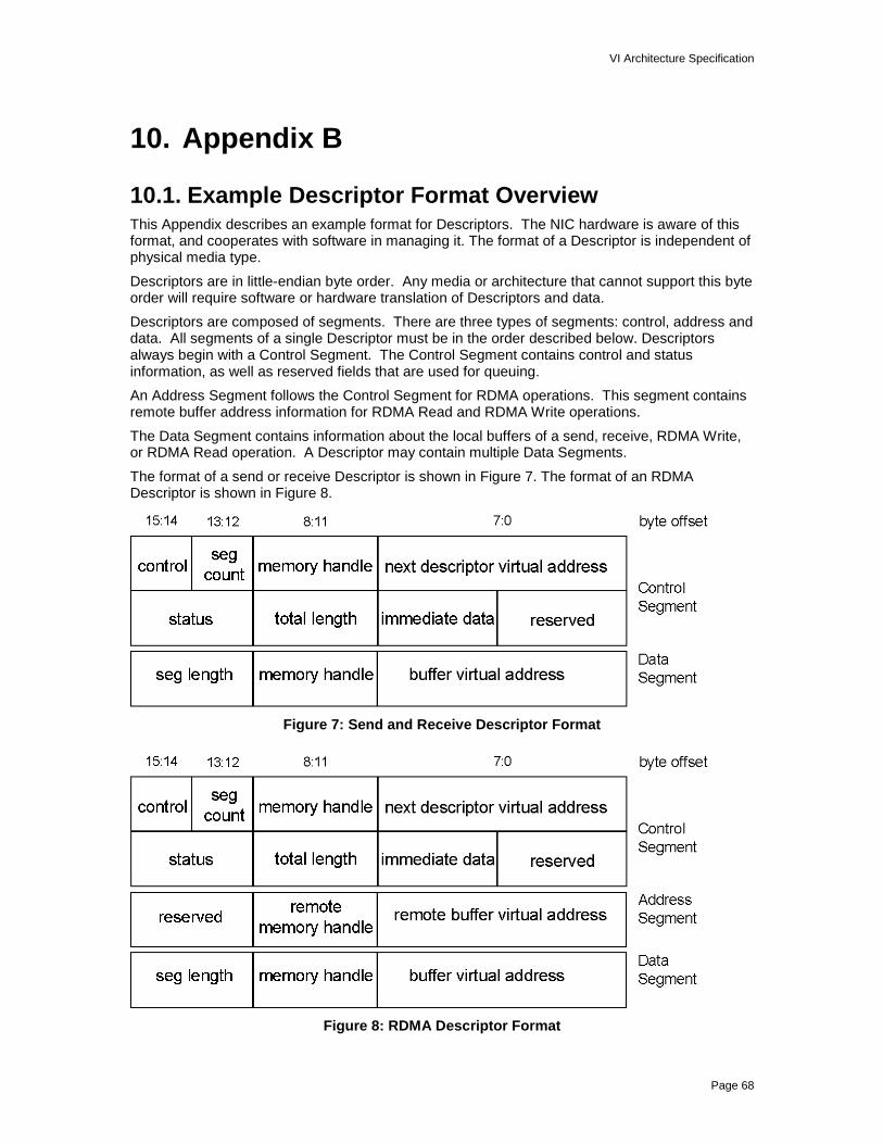
VI Architecture Specification
Page 68
10. Appendix B
10.1. Example Descriptor Format OverviewThis Appendix describes an example format for Descriptors. The NIC hardware is aware of thisformat, and cooperates with software in managing it. The format of a Descriptor is independent ofphysical media type.
Descriptors are in little-endian byte order. Any media or architecture that cannot support this byteorder will require software or hardware translation of Descriptors and data.
Descriptors are composed of segments. There are three types of segments: control, address anddata. All segments of a single Descriptor must be in the order described below. Descriptorsalways begin with a Control Segment. The Control Segment contains control and statusinformation, as well as reserved fields that are used for queuing.
An Address Segment follows the Control Segment for RDMA operations. This segment containsremote buffer address information for RDMA Read and RDMA Write operations.
The Data Segment contains information about the local buffers of a send, receive, RDMA Write,or RDMA Read operation. A Descriptor may contain multiple Data Segments.
The format of a send or receive Descriptor is shown in Figure 7. The format of an RDMADescriptor is shown in Figure 8.
Figure 7: Send and Receive Descriptor Format
Figure 8: RDMA Descriptor Format
VI Architecture Specification
Page 69
10.2. Descriptor Control SegmentThe fields of a Control Segment are described below. All Reserved fields must be zero or aformat error will occur.
Next Descriptor Virtual Address (control segment bytes 7:0):
This field links a series of Descriptors to form the send and receive queues for a VI. Thevalue is the virtual address of the next Descriptor on a queue. A VI Consumer fills in thisfield in the Descriptor that is currently the tail of a queue to add a new Descriptor to thequeue.
Next Descriptor Memory Handle (control segment bytes 11:8)
This field is the matching memory handle for the Next Descriptor Virtual Address. A VIConsumer fills in this field when it fills in the Next Descriptor Virtual Address field.
Descriptor Segment Count (control segment bytes 13:12)
This field contains the number of segments following the Control Segment, including theAddress Segment, if present. A VI Consumer sets this field when formatting theDescriptor.
Control Field (control segment bytes 15:14)
This field contains control bits or information pertaining to the entire Descriptor. The VIConsumer sets the bits in this field when formatting the Descriptor. These bits indicatespecific actions to be taken by the VI when processing the Descriptor.
This Control Field contains sub-fields, as follows:
Control field bits 1:0: Operation Type
Defines the operation for this Descriptor. Acceptable values are:
00: Indicates that this is a Send operation if this Descriptor is posted on the sendqueue. Indicates that this is a Receive operation if this Descriptor is postedon the receive queue.
01: Indicates that this is a RDMA Write Descriptor if posted on the send queue.This value is invalid if this Descriptor is posted on the receive queue, and willresult in a format error.
10: Indicates that this is a RDMA Read Descriptor if posted on the send queue.This value is only valid if the underlying VI Provider supports RDMA Readoperations. This value is invalid if this Descriptor posted on the receivequeue, and will result in a format error.
11: This value is undefined and will result in a format error.
Control field bit 2: Immediate Data Indication
If this bit is set, it indicates that there is valid data in the Immediate Data field ofthis Descriptor.
If this is a Send Descriptor, it indicates that the data in the Immediate Data field isto be transferred to the corresponding Receive Descriptor on the remote end ofthe connection.
If this is an RDMA Write Descriptor, it indicates that the data in the ImmediateData field is to be transferred to the corresponding Receive Descriptor on theremote end of the connection. Normally RDMA Writes do not consumeDescriptors on the remote node, but Immediate Data will cause this to happen.
This bit is ignored for RDMA Read operations. Immediate Data is not transferredwith RDMA Read operations. This will not result in a format error. TheImmediate Data is simply ignored.

VI Architecture Specification
Page 70
If this is a pending Receive Descriptor, this bit is ignored. Once the Descriptor iscompleted, this bit is used to indicate that the Immediate Data contains valid datathat was sent from the connected VI.
Control field bit 3: Queue Fence
The Queue Fence bit, when set, inhibits processing of the Descriptor until allprevious RDMA Read operations on the same queue are complete. This featureis discussed in section 6.3.1.2.
Control field bits 15:4: Reserved
These bits are reserved for future use. They must be set to zero by the VIConsumer or a format error will occur.
Reserved (control segment bytes 19:16):
This field is a reserved field. It must be set to zero by the VI Consumer or a format errorwill result.
Immediate Data (control segment bytes 23:20):
This field allows 32 bits of data to be transferred from the Descriptor of a Send or RDMAWrite operation to a corresponding Descriptor in the connected VI’s Receive Queue.Immediate Data is used in conjunction with the Immediate Data Indication bit of theControl Field in the Control Descriptor.
This field is optionally set by the VI Consumer in the case of Send and RDMA Writeoperation and is returned to the VI Consumer in the case of Receives. The ImmediateData field is ignored for RDMA Read operations.
Length Field (control segment bytes 27:24)
This field contains the total length of the data described by the Descriptor. The VIConsumer sets this field when formatting the Descriptor. For send Descriptors, this fieldmust specify the sum of the Local Buffer Length fields of all Data Segments for thepacket. For outstanding receive Descriptors, this field is undefined. The VI NIC will usethe length parameters in the individual Data Segments when determining receptionlength.
Upon completion of data transfer, this field is set by the VI NIC to reflect the total numberof bytes transferred from, in the case of a Send or RDMA Write, or to, in the case ofReceive or RDMA Read, the Data Segment buffers. If the Descriptor completed with anerror, the Length field is undefined.
Status (control segment bytes 31:28):
This field contains status information that is written by a VI NIC in order to complete aDescriptor. A VI Consumer polls for completion of a Descriptor by reading this field in theWork Queue completion model. In general, the format of the status field is that bits 0:15allow the VI Consumer to easily check for successful completion or for completion inerror. Bits 16:31 contain flags to provide additional information to the VI Consumer. TheVI Consumer must set this field to zero before posting a Descriptor.
The format for the Status Field is shown below.
Figure 9: Status Field Format
The individual bits of the Status Field are defined as follows:
VI Architecture Specification
Page 71
Status Field, bit 0: Done
This bit is set to 1 by a VI Provider to indicate that Descriptor execution hascompleted. Zeroes in bits 1 through 15 of the status field indicate successfulcompletion. A 1 in any of the bits 1 through 15 of this field indicates that an errorwas detected during Descriptor execution.
This bit in the Descriptor is set according to the level of reliability of theConnection, as discussed in Section 2.5.
Status Field, bit 1: Local Format Error
This field is set if the locally posted Descriptor has a format error. This includeserrors such as invalid operation codes, reserved fields set by the software andinvalid VI Identifiers. It does not include errors covered by other error bits.
This bit is valid on all Descriptor and Connection types.
Status Field, bit 2: Local Protection Error
This field is set if the locally posted Descriptor’s data segment address andmemory handle pair does not point to a protection table entry that is valid for therequested operation. This may indicate a bad memory handle, a bad virtualaddress, mismatched protection tags, or insufficient rights for the requestedoperation.
This bit is valid on all Descriptor and Connection types.
Status Field, bit 3: Local Length Error
This field is set if the sum of the locally posted Descriptor’s Data Segmentlengths exceed the VI NIC’s MTU on a Descriptor posted to the send queue. Itwill also be set if the total of the locally posted Descriptor’s data segment lengthsdoes not match the control segment length field of a Descriptor posted to thesend queue.
This bit will be set if the total of the locally posted Descriptor’s data segmentlengths is too small to receive the incoming packet for Descriptors posted to theReceive Queue.
This bit is valid on all Descriptor and Connection types.
Status Field, bit 4: Partial Packet Error
This bit will be set on a Descriptor posted to the send queue if an error wasdetected after a partial packet was put on the fabric. This bit will be set inconjunction with another bit that indicates the error causing the abort.
For Descriptors posted to the receive queue, this bit indicates and aborted ortruncated packet was received.
This bit is valid on all Descriptor and Connection types.
Status Field, bit 5: Descriptor Flushed
This bit indicates that the Descriptor was flushed from the queue when the VIwas disconnected. The VI may have been disconnected either explicitly or dueto an error.
This bit is valid on all Descriptor and Connection types.
Status Field, bit 6: Transport Error
This bit is used to indicate that there was an unrecoverable data error, data couldnot be transferred, data was transferred but corrupted, the correspondingendpoint was not responding or VI NIC link problem. If this bit is set, the VI hastransitioned to the Error state.
VI Architecture Specification
Page 72
On Unreliable connections, this bit is only valid on Receive Descriptors. ForReliable Delivery connections, this bit is only valid on receive and RDMA ReadDescriptors. On Reliable Reception connections, this bit is valid on all types ofDescriptors.
Status Field, bit 7: RDMA Protection Error
This bit is set if the source of the RDMA Read, or destination of an RDMA Write,had a protection error detected at the remote node.
This bit is not valid for Descriptors on Unreliable Connections. For ReliableDelivery Connections, this bit is set only on RDMA Read Descriptors. OnReliable Reception Connections, this bit is set either on RDMA Read or RDMAWrite Descriptors. This bit is not set on other Descriptor types.
Status Field, bit 8: Remote Descriptor Error
This bit is set if there was a length, format, or protection error in a Descriptorposted at the remote node. It is also set if there was no receive Descriptorposted for the incoming packet.
For Unreliable and Reliable Delivery Connections, this bit is not valid for anyDescriptor posted. For Reliable Reception Connections, this bit is only set onSend Descriptors and RDMA Write Descriptors with Immediate Data.
Status Field, bits 15:9: Reserved Error Bits
These bits are reserved for future use and must be set to zero by VI Providerscomplying with this version of the specification.
Status Field, bits 18:16: Completed Operation Code
This field describes the type of operation completed for this Descriptor. Thecodes within this field are arranged such that the least significant bit (LSB)denotes the queue on which this operation completed. An LSB of zero denotesthat the operation completed on the Send Queue, while an LSB of 1 denotes thatthe operation completed on the Receive Queue. The possible (binary) valuesare:
000b: Send operation completed.
001b: Receive operation completed.
010b: RDMA Write operation completed.
011b: Remote RDMA Write operation completed. This value indicatesthat an RDMA Write operation that was initiated on the remote end of theconnection completed and consumed this Descriptor (implying thatimmediate data is available in the Immediate Data field).
100b: RDMA Read operation completed (if supported, otherwiseundefined).
101b through 111b: are undefined.
Status Field, bit 19: Immediate Flag
This bit is set when the Immediate Data field is valid for a Descriptor on theReceive queue. The Immediate Flag is set at the completion of a Receiveoperation, or at the target side of a RDMA Write operation when a ReceiveDescriptor is consumed.
Status Field, bit 31:20 Reserved Flag Bits
These bits are reserved for future use and must be set to zero by VI Providerscomplying with this version of the specification.

VI Architecture Specification
Page 73
10.3. Descriptor Address SegmentThe second Segment in a Descriptor is the Address Segment. This segment is only included inRDMA operations. It is not included in normal Send operation nor in Receive Descriptors of anytype, since all RDMA requests are posted to the Send queue.
The purpose of this segment is to identify to the VI NIC the virtual address on the remote nodewhere the RDMA Data is to be read from or written to. The virtual address must reside in aMemory Region registered by the process associated with the remote VI. The remote virtualaddress and corresponding memory handle must be known to the local process before an RDMArequest is initiated.
Remote Buffer Virtual Address (address segment bytes 7:0):
For an RDMA Write operation, this value specifies the virtual address of the destinationbuffer at the remote end of the connection. For RDMA Read operation, it specifies thesource buffer at the remote end of the connection.
Remote Buffer Memory Handle (address segment bytes 11:8):
This field contains the memory handle that corresponds to the Remote Buffer VirtualAddress.
Reserved (address segment bytes 15:12):
This field is reserved, and must be set to zero by the VI Consumer or the Descriptor willbe completed in error due to a format error.
10.4. Descriptor Data SegmentZero or more Data Segments can exist within a Descriptor.
Every VI NIC has a limit on the number of Data Segments that a Descriptor may contain. All VINICs must be able to handle at least 252 Data Segments in a single Descriptor. Each VI Providershould supply a mechanism by which a VI Consumer can determine the maximum number ofData Segments supported by the Provider.
The minimum number of Data Segments that can be included in a Descriptor is zero. It ispossible to send only Immediate Data in a Descriptor, although even that need not be sent.
The total sum of the buffer lengths described by the Data Segments in a Descriptor cannotexceed the MTU of the VI NIC or a length error will result.
Local Buffer Virtual Address (data segment bytes 7:0):
This field contains the virtual address of the data buffer described by the segment. Thisfield must be filled in by the VI Consumer.
Local Buffer Memory Handle (data segment bytes 11:8):
This field contains the corresponding Memory Handle for the Local Buffer VirtualAddress.
Local Buffer Length (data segment bytes 15:12):
This field contains the length of the Local Buffer pointed to by the Local Buffer VirtualAddress field. Zero is a valid value for this field.

VI Architecture Specification
Page 74
11. Appendix C
11.1. Example Hardware Model OverviewThis Appendix describes an example hardware model for a VI NIC. Also included is a discussionof the associated VI Kernel Agent. The reader can use this chapter to help solidify thearchitectural concepts previously discussed. Implementers may wish to use the example modelas a starting point for their own design.
11.2. Example VI NICThis section describes an example hardware model for a VI NIC.
The VI Architecture relies on a significant portion of the functionality to be implemented in VI NIChardware to achieve the lowest communication latency. The following diagram shows theexample VI NIC hardware model:
NIC to Host InterfaceDoorbellSpace
NIC RegSpace
GlobalInterruptQueue
HostCPU(s)
VIQueues
& Buffers
StatusWrites
InterruptSignals
MemoryMappedAccesses
DMAAccesses
MemoryMappedAccesses
HostMemory
VI (n)Context
Common ControlHardware
(Queue Management)
MultiplexedI/O Traffic
Per-VIStatus
NICControl
& Status
Per-VIDoorbell Tokens &Interrupt Enables
I/OData
Transmit & ReceiveHardware
Figure 10: VI NIC Hardware Model
This hardware controls a set of Virtual Interfaces and schedules (multiplexes) between them in anorder determined by a transmit scheduling mechanism and an input data stream.
It virtualizes the hardware interfaces and associates each with a VI by storing context for each VIand each direction of transfer. When the common hardware executes a time slice for a given VIand direction, it uses the corresponding context to control the operation of the common hardware.
It multiplexes data traffic from host memory through the NIC out to the network in an orderdetermined by a transmit scheduler and keeps the transmit hardware fed from host memoryaccordingly.
VI Architecture Specification
Page 75
It executes virtualized receive interfaces and feeds receive data to host memory in an orderdetermined by the order of packets received from the network.
It manages the network side of all VI queues and directly accesses queues and buffers in hostmemory through DMA transactions.
It recognizes transactions to Doorbell pages within the host’s physical address space and inresponse, tracks the number of Descriptors posted on each VI queue.
It translates virtual address information received in Descriptors, Doorbell tokens, and RDMApseudo addresses to physical addresses and ensures that the owner of the associated VI alsoowns the physical memory addressed.
It provides asynchronous notification of significant events to the host through DMA writes of per-VI interrupt status words to a global interrupt queue in host memory. In addition, when necessary,it uses an interrupt signal to invoke execution of the interrupt handler of its associated VI KernelAgent.
It enables the host to access registers and memories on the NIC via programmed I/Otransactions by kernel level driver software to provide overall control and initialization of thehardware resources.
11.2.1. Hardware Interface
11.2.1.1. Address TranslationMemory is registered with the VI NIC for two reasons:
1) to allow the NIC to perform virtual to physical address translation
2) to allow the NIC to perform protection checking.
Consumers are able to use virtual addresses to refer to VI Descriptors and communicationbuffers. The VI NIC is able to translate from virtual to physical addresses through the use of itsTranslation and Protection Table (TPT). The TPT of the example NIC resides on the NIC in orderto assure fast, non-contentious access and because it is accessed during performance criticaldata movement. The fields of each TPT entry are:
a) a physical page address
b) a protection tag
c) an RDMA Write Enable Bit
d) an RDMA Read Enable Bit
e) a Memory Write Enable Bit
The size of the TPT is configurable. There is one entry in the TPT for each page that can beregistered by the user. A memory region of N contiguous virtual pages consumes N contiguousentries in the TPT.

VI Architecture Specification
Page 76
2000
PhysicalPages
9000
VirtualPages
4000
A000
7000
B000
-
M em oryHandle
4000 Tag X
2000 Tag X
7000 Tag X
PhysicalPage
AddressProtection
Tag
Process usingVI with Tag X
TPT
NIC
ProtectionIndex
VirtualAddress
Figure 11: Translation and Protection Table
When a memory region is registered with the NIC, the Kernel Agent allocates a contiguous set ofentries from the TPT and initializes them with the corresponding physical page addresses andprotection tag specified by the process that registered the memory region. The protection tagspecified by the process when it creates a VI is stored in the context memory of the VI. The NIChas access to the protection tag in both of these areas, allowing it to compare these values todetect invalid accesses
Page sizes larger than 4KB are supported and page size may differ among nodes of the SAN.For page sizes larger than 4KB the low order bits of the memory handle are sacrificed to makeroom for an offset field larger than 12 bits. This reduces the number of pages that can bemapped, but the amount of memory that can be registered is constant regardless of the page size
On a node with a page size larger than 4KB the 32-bit memory handle is returned from theregister memory operation with the corresponding low order bits set to 0. The example hardwaremodel has a TPT with 232 entries. Only 244 bytes of the virtual address space may be mapped bythe TPT at any time; i.e., the number of bits used for the offset and the significant number of bitsin the handle are a total of 44 bits.
A pseudo address is an internal construct that supports remote-DMA operations. The pseudoaddress is transmitted from the RDMA initiator (in a control field of the RDMA request) to specifythe remote address to read from or write to. Pseudo addresses are formed from virtual addressesby multiplying the corresponding protection index (see Figure 11) by the page size and adding thepage offset.
Because of the scheme described above for support of page sizes larger than 4KB, thecalculation of a pseudo address can be done without knowing the page size of the remote node.
11.2.1.2. DoorbellsA Doorbell is a window in memory that allows a process to inform the NIC that a new Descriptoris available on a Work Queue. There is a Doorbell for every Work Queue. With respect to aprocess, a Doorbell is a location in its virtual address space. With respect to the NIC, a Doorbell

VI Architecture Specification
Page 77
is a memory mapped control register. The Kernel Agent provides Doorbell mappings for allprocesses and Work Queues.
To ring a Doorbell software writes a Doorbell token to a Doorbell register. Upon receiving theDoorbell token the NIC increments a counter of outstanding requests on the associated WorkQueue. Whenever the NIC completes processing of a Descriptor it decrements the counter ofoutstanding requests. The counter allows the NIC to determine whether there is work pending ona Work Queue.
The format of the Doorbell token is shown in Table 2 below. The Doorbell is 64 bits long tosupport up to 64 bit addressing. If the host supports atomic 64 bit writes then the entire Doorbellcan be written at once. If the host only supports 32 bit atomic writes then only the low-order 32bits of the Doorbell can be written and addressing is limited to 32 bits. When the NIC sees a 32bit write to the Doorbell it assumes the high-order 32 bits of the token are zero.
Table 2: Doorbell Token Format
Bits Use Description
63:44 Unused
43:X Protection Index The protection index corresponding to the registered virtualaddress of the Descriptor for the current data movementoperation request.
X-1:6 Descriptor Offset The offset, in 64-byte increments, into the physical page wherethe newly posted Descriptor starts. The physical page size forthe host system determines how many bits are in this field.
5:0 Reserved Reserved for future use.
Where X is the number of bits in the offset portion of a virtual address; e.g., 12 for a 4KB pagesize
Descriptors are posted by en-queuing them on the tail of a send or receive Work Queue andwriting a token to the VI’s corresponding send or receive Doorbell. Doorbell tokens are formedusing the following calculation:
Doorbell Token = Virtual Address of Descriptor - (Handle << 12)
11.2.1.3. Marking CompletionWhen the NIC finishes processing a Descriptor it writes the status and length back to theDescriptor. Included in the status is the ‘done’ bit, which passes control back to the VI Consumerfrom the VI NIC.
If there is a Completion Queue associated with the VI then information identifying the VI andqueue (i.e., send or receive) on which the operation completed is written to the next CompletionQueue entry and the Completion Queue pointer is incremented.
11.2.1.4. NIC Context
11.2.1.4.1. Per-VI NIC Context

VI Architecture Specification
Page 78
For each VI the NIC keeps the following context:
• Protection tag associated with the VI
• An RDMA Read enable bit
• An RDMA Write enable bit
• The Maximum Transfer Size for this VI
For each send and receive Work Queue on each VI the NIC keeps the following context:
• Count of outstanding operations on the queue
• Address of next Descriptor on the queue
• Reference to Completion Queue associated with the queue (NULL if none)
• Indicator as to whether interrupts are enabled for the queue (NA if a Completion Queue isassociated with the VI)
11.2.1.4.2. Per-Completion Queue NIC Context
For each Completion Queue the NIC keeps the following context:
• Address of start of Completion Queue
• Number of entries in Completion Queue
• Address of next entry in Completion Queue
• Indicator of whether interrupts are enabled for this Completion Queue
11.2.1.5. Packet FormatA network packet consists of a header, a data payload, and a payload CRC. One network packetis generated for each Descriptor placed on a send Work Queue.
Note: The example hardware model assumes a single network frame per packet. A morecomplex implementation may break a packet into a series of cells to prevent a single large packetfrom tying up the network for long periods.
11.2.1.5.1. Packet Header
Each network packet contains a header consisting of the following fields:
• The VI for which the packet is intended
• An opcode specifying the operation to perform; i.e., SEND, RDMA Write, RDMA Read-Request, or RDMA Read-Reply
• Immediate data (NA for RDMA Read)
• Byte count; this is the length of the payload for send and RDMA/Write, and the number ofbytes to read in the case of RDMA Read
• A pseudo address of the region to read or write (RDMA operations only)
• CRC covering the header
11.2.1.5.2. Data Payload
Concatenation of all the data buffers specified in the data segment of the send or RDMA/WriteDescriptor. The data payload is of length 0 for RDMA Read-Request.
11.2.1.5.3. Payload CRC
CRC covering the data payload, it is ignored in the case of RDMA Read-Request.

VI Architecture Specification
Page 79
11.2.2. NIC Hardware Functions
11.2.2.1. Transmit Hardware FunctionsThe transmit hardware for a VI NIC reads a Descriptor from host memory, generates the CRC-32values for the header and trailer, assembles a complete physical layer frame and transmits theframe to the network. Each time a frame is transmitted the NIC writes completion status to thecorresponding send Descriptor. If a Completion Queue is associated with the send Work Queuecompletion status is also written to the next Completion Queue entry. If interrupts are enabled forthe send Work Queue the NIC issues an interrupt.
A round-robin transmit scheduling mechanism is used to ensure timely servicing of all active sendqueues and provide fairness in arbitration between VIs. This functionality must be implemented inhardware to provide efficient multiplexing between a large number of VIs.
11.2.2.2. Receive Hardware FunctionsVI receive queues are serviced according to the sequence that frames are received from the VIfabric. The NIC attempts to always have the Descriptor segments for each active VI pre-fetchedand ready for execution when the corresponding frame is received; note, however, that not allincoming frames consume a Descriptor.
The receive hardware reads the frame header from the network and checks the header CRC.Further processing of incoming frames depends on the opcode contained in the header:
Send: If the frame header control field indicates there is immediate data it is copied to thecorresponding receive Descriptor’s immediate data field. The NIC then sets up DMA operations tocopy data from the frame payload into the memory regions specified by the receive Descriptor’sdata segments. When processing of a frame completes the NIC writes completion status to thereceive Descriptor. If a Completion Queue is associated with the receive Work Queue thencompletion status is also written to the next Completion Queue entry. If interrupts are enabled forthe receive Work Queue then the NIC issues an interrupt.
RDMA/Write: The NIC sets up DMA operations to copy data from the frame payload into thememory region specified by the RDMA pseudo address field of the frame header. If the frame’scontrol field header indicates there is no immediate data associated with this RDMA/Write then noreceive Descriptor is consumed, no completion status is written, and no interrupts are generated.
If the frame header control field indicates that there is immediate data it is copied to thecorresponding receive Descriptor’s immediate data field and the NIC writes completion status tothe receive Descriptor. If a Completion Queue is associated with the receive Work Queuecompletion status is also written to the next Completion Queue entry. If interrupts are enabled forthe receive Work Queue then the NIC issues an interrupt.
Read-Request: A Read-Request opcode indicates the initiation of an RDMA Read operation.The reference implementation does not specify RDMA Read operation.
Read-Reply: A Read-Reply opcode indicates the reply to an RDMA Read operation. Thereference implementation does not specify RDMA Read operation.
11.2.2.3. Interrupt SupportThe example VI hardware model provides a global interrupt queue. The NIC writes entries to thequeue in response to events generated at both the VI level and the NIC level. Entries in the globalinterrupt queue contain an interrupt code and identify whether the interrupt was for a particular VIand Work Queue, Completion Queue or is related to the NIC as a whole.
The VI architecture requires support for two kinds of asynchronous events: completions anderrors. The flow diagram in Figure 12 shows the hardware and software model for handling theseevents. Note that Figure 12 assumes that the thread entering the wait path has mutually exclusive

VI Architecture Specification
Page 80
access to the VI work queue. Only those errors that cannot be reported through Descriptor statusare reported asynchronously.
®
Hardware
VI Level Interrupt State Machine
SoftwareVI Programming Interface
Update QueueHead Pointer
Target DescriptorDone?
no
Enable VIDone Interrupt
yes
VI DoneInterrupt Enabled?
yes yes
Send VIDone InterruptDisable VIDone Interrupt
no
Wait Primitive Return
Non-DescriptorVI Error?
no
VI Error InterruptEnabled?
yes
Target Descriptor Done?
yes
no
Disable VIDone Interrupt
Sleep,Wait for DoneNotification
Send DoneNotification
OS
no
Done Interrupt status
Target DescriptorDone?
yes
no
no
yes
Send VIError Interrupt,ClearError Status,Disable VIError Interrupt
NIC InterruptHandler
Send ErrorNotification
Error Interruptstatus
NIC Driver
Handle Error,Re-enable ErrorInterrupt
Wake-up Wake-up
Init Error Thread
Record ErrorStatus
VI DescriptorDone?
Sleep,Wait for ErrorNotification
Figure 12: Asynchronous Event Model
11.3. Kernel Agent Example
This section is a functional description of a VI Kernel Agent associated with the example VI NIChardware.
The VI Kernel Agent implements the set of software services inside the target operating system. Itis implemented as a kernel-mode driver containing control and resource management functions.They reside in the kernel to provide centralized control and trusted operation using the facilities ofthe operating system itself.
Functionally, the services are:
• Network Device Control and Management
• Virtual Interface Resource Management
• Completion Queue Resource Management
• Host Memory Management
• Connection Management

VI Architecture Specification
Page 81
• Asynchronous Error Delivery
11.3.1. NIC InitializationThe Kernel Agent is responsible for initializing its internal state, as well as the NIC hardware atthe time that it is first invoked. Normally, the Kernel Agent will perform initialization at systeminitialization time, or at the time that it is loaded and initially entered by its host operating system.
11.3.2. Interrupt ProcessingThe Kernel Agent is responsible for the handling of all NIC device interrupts. When the KernelAgent initializes, it must register itself with the OS in order to receive interrupts from its associatedVI NIC. When interrupts are generated by the NIC, it must dispatch them to the proper threadthat is waiting for the event.
11.3.3. Memory RegistrationThe memory registration function is implemented in the Kernel Agent. Kernel mode privilege isrequired in order to translate the caller’s virtual address to physical addresses, to lock the pagesinto physical memory, and to access the protection entries of the VI NIC.
Refer to the example function VipRegisterMem in Section 9.5.3.
11.3.4. Memory De-registrationMemory de-registration is implemented in the Kernel Agent. Kernel mode privilege is required tounlock the caller’s pages from physical memory and to invalidate the protection entries of the VINIC.
Refer to the example function VipDeregisterMem in Section 9.5.4.
11.3.5. Setting and Querying Memory AttributesThe memory attributes for a registered memory region are managed in the Kernel Agent. Itmaintains the state of each memory region and sets the appropriate flags in the protection entriesof the VI NIC.
The memory attributes that are visible to the VI Consumer are the Protection Tag, the RDMAWrite Enable and the RDMA Read Enable. The example Kernel Agent also maintains anadditional bit, the Memory Write Enable bit. The Memory Write Enable allows the Kernel Agent tocheck for pages that are marked as read-only by the Virtual Memory system, and protect themfrom being modified by the VI NIC.
Refer to the example functions VipSetMemAttributes and VipQueryMem in Section 9.
11.3.6. VI CreationCreates a new Virtual Interface instance, allocates its resources and sets the initial state. Itreturns a VI identifier to the calling process along with the information needed in order tomanipulate that VI.
Refer to the example function VipCreateVi in Section 9.3.1.
11.3.7. VI DestructionTears down a Virtual Interface, and frees any associated resources in kernel memory, as well ason the VI NIC. If the specified VI is not in the idle state, or if all of the Descriptors have not beende-queued from its work queues, the VI will not be destroyed.
Refer to the example function VipDestroyVi in Section 9.3.2.
VI Architecture Specification
Page 82
11.3.8. Setting and Querying VI AttributesThe Kernel Agent manages the attributes of a VI. It maintains the state of each VI instance andsets the appropriate state in the VI NIC. The initial attributes of the VI are set when the VI iscreated. VI attributes can subsequently be changed. If the VI is in a state such that changing theattributes would cause non-deterministic behavior, the request to change the attributes fails.Querying the attributes of a VI simply passes the current values back to the caller.
Refer to the example functions VipSetViAttributes and VipQueryVi in Section 9.
11.3.9. Protection Tag CreationCreates a new protection tag for a specified NIC instance.
Protection tags must be unique identifiers for a particular instance of a NIC. Protection tags aresubsequently associated with VI endpoints, and with registered memory regions. The protectiontag needs a reference count to ensure that they cannot be destroyed while associated with anactive VI, or with a registered memory region.
Refer to the example function VipCreatePtag in Section 9.5.1.
11.3.10. Protection Tag DestructionDestroys a previously created protection tag. A protection tag should not be destroyed unless ithas no current associations to VI instances or registered memory regions.
Refer to the example function VipDestroyPtag in Section 9.5.2.
11.3.11. Connection ManagementThe Kernel Agent implements all connection management operations.
Refer to the example functions VipConnectWait, VipConnectRequest, VipConnectAccept andVipConnectReject in Section 9.4.
11.3.12. Block on Send and ReceiveFor the example VI NIC, the blocking semantics for send are implemented directly in the KernelAgent. The block on send function blocks the calling thread until a done interrupt is generated bythe NIC for the associated VI Work Queue.
11.3.13. Create Completion QueueCreates a new Completion Queue instance, allocates its resources and sets the initial state. Itreturns a Completion Queue identifier to the calling process along with the information needed inorder to manipulate that Completion Queue.
Refer to the example function VipCreateCQ.
11.3.14. Resize Completion QueueThe kernel agent implements the resizing of Completion Queues. This operation allows the VIConsumer to dynamically grow or shrink the number of entries that the Completion Queue canpotentially hold. The Kernel Agent is responsible for allocating the resources and registeringthem with the NIC in support of the Completion Queue structure.
For the hardware example, three steps are performed by this function:
1. A new Completion Queue is created.

VI Architecture Specification
Page 83
2. The NIC is informed of the new Completion Queue parameters, such as the queueaddress and size; once it knows of the new Completion Queue the NIC places allsubsequent completion status in the new queue.
3. At the point that software next checks the original previous Completion Queue andfinds no completed entry, software starts using the new queue, and can destroy theprevious queue. This solution requires that software must be able to atomically changethe Completion Queue address and length parameters stored in the NIC.
Refer to the example function VipResizeCQ in Section 9.7.3.
11.3.15. Block on Completion QueueIn this reference, the blocking semantics for Completion Queues is implemented directly in theKernel Agent. The block on Completion Queue function blocks the calling thread until a doneinterrupt is generated by the NIC for the associated VI.
11.3.16. Destroy Completion QueueDestroys a Completion Queue instance and de-allocates its resources.
Refer to the example function VipDestroyCQ in Section 9.7.2.
11.3.17. Error CallbackIt is the responsibility of the Kernel Agent to associate completion events with Consumerspecified error handler functions, and to deliver all asynchronous errors to the Consumer.
11.3.18. Resource cleanupWhen a process exits, a mechanism must be provided to allow the Kernel Agent to de-allocate allof its resources associated with that VI Provider. Normal OS mechanisms must allow the KernelAgent to be notified when a process exits so that it can do resource cleanup. The Kernel Agentkeeps track of all per-process resources associated with a Consumer’s access to a NIC.