virtual infrastructure for wireless ad hoc networks seth gilbert
TRANSCRIPT
Virtual Infrastructure for
Wireless Ad Hoc Networks
by
Seth Gilbert
Submitted to theDepartment of Electrical Engineering and Computer Science
in partial fulfillment of the requirements for the degree of
Doctor of Philosophy
at the
MASSACHUSETTS INSTITUTE OF TECHNOLOGY
August 2007
c© Massachusetts Institute of Technology 2007. All rights reserved.
Author . . . . . . . . . . . . . . . . . . . . . . . . . . . . . . . . . . . . . . . . . . . . . . . . . . . . . . . . . . . . . .
Department of Electrical Engineering and Computer ScienceAugust 23, 2007
Certified by. . . . . . . . . . . . . . . . . . . . . . . . . . . . . . . . . . . . . . . . . . . . . . . . . . . . . . . . . .Nancy Lynch
NEC Professor of Software Science and EngineeringThesis Supervisor
Accepted by . . . . . . . . . . . . . . . . . . . . . . . . . . . . . . . . . . . . . . . . . . . . . . . . . . . . . . . . .Arthur C. Smith
Chairman, Department Committee on Graduate Students

2

Virtual Infrastructure forWireless Ad Hoc Networks
bySeth Gilbert
Submitted to theDepartment of Electrical Engineering and Computer Science
on August 23, 2007, in partial fulfillment of therequirements for the degree of
Doctor of Philosophy
Abstract
One of the most significant challenges introduced by ad hoc networks is coping withthe unpredictable deployment, uncertain reliability, and erratic communication exhib-ited by emerging wireless networks and devices. The goal of this thesis is to develop aset of algorithms that address these challenges and simplify the design of algorithmsfor ad hoc networks.
In the first part of this thesis, I introduce the idea of virtual infrastructure, anabstraction that provides reliable and predictable components in an unreliable andunpredictable environment. This part assumes reliable communication, focusing pri-marily on the problems created by unpredictable motion and fault-prone devices. Iintroduce several types of virtual infrastructure, and present new algorithms basedon the replicated-state-machine paradigm to implement these infrastructural compo-nents.
In the second part of this thesis, I focus on the problem of developing virtualinfrastructure for more realistic networks, in particular coping with the problem ofunreliable communication. I introduce a new framework for modeling wireless net-works based on the ability to detect collisions. I then present a new algorithm forimplementing replicated state machines in wireless networks, and show how to usereplicated state machines to implement virtual infrastructure even in an environmentwith unreliable communication.
Thesis Supervisor: Nancy LynchTitle: NEC Professor of Software Science and Engineering
3

4

Acknowledgments
In many ways, the best part of my years at MIT has been the amazing people that Ihave had the opportunity to meet, to collaborate with, and—in many cases—to getto know personally. Without their ideas, their enthusiasm, and their support, thisthesis would never have happened.
The Thesis Committee
First and foremost, I would like to thank Nancy Lynch. Even more than herindispensable advice and technical skill, it has been her enthusiasm and positiveattitude that has made this thesis possible. From the very first time we met, she wassaying, “I think there’s some exciting stuff to work on here!”
I would also like to thank the other members of my thesis committee, Erik De-maine, Sam Madden, and Jennifer Welch. They have provided valuable feedbackand interesting perspectives on the ideas contained in this thesis.
The Virtual Infrastructure Project
I would like to call particular attention to the role played by Jennifer Welch andShlomi Dolev, both early collaborators on this project. Many of the ideas presentedin this thesis have grown out of conversations and e-mails with Jennifer and Shlomi,who posed the original question, “What sort of useful things can we do with swarmsof mobile nodes?” It was this question that led to the “GeoQuorums approach” todeveloping algorithms for mobile ad hoc networks [32], which then evolved into theidea of virtual infrastructure. I am ever grateful for their friendly and welcomingattitude, and for their help on this project.
Alex Shvartsman was also an important contributor to the initial developmentof virtual infrastructure. Aside from his role in this thesis, he was also a source ofhelpful advice in the transition from industry to graduate school, and was a vitalcollaborator on my master’s thesis.
Tina Nolte has been another key contributor to the virtual infrastructure project.Her work on timing-related issues (e.g., [29, 30]), self-stabilization (e.g., [35]), andapplications (e.g., [83]) has played an important role in further developing the ideasin this thesis. Of particular interest is the idea of using virtual infrastructure for thepurpose of coordinating the motion of mobile entities, first developed in a paper bySayan Mitra, Tina Nolte, and Nancy Lynch [69]. Others who have been a partof the virtual infrastructure project include Elad Schiller and Limor Lahiani. Iwould also like to mention Matthew Brown and Michael Spindel who have pioneeredthe implementation of virtual infrastructure.
Many of the ideas developed in the second part of this thesis have grown out ofconversations with Gregory Chockler, Calvin Newport, and Murat Demirbas.Together, we developed a model for wireless networks that accounts for contention andcollisions on the communication channel; together we developed new algorithms forconsensus in wireless networks that led directly to the emulation algorithm describedin Chapter 10. More recently, Calvin Newport has been developing new ideas that
5

extend the virtual infrastructure notion presented in this thesis, considering prob-lems caused by un-cooperative (perhaps, malicious) devices, and studying the uses ofvirtual infrastructure in the context of routing.
Collaborators and Colleagues
I have been fortunate to work with many other excellent collaborators and colleaguesduring my years at MIT. Let me begin by thanking Charles Leiserson, who hasbeen an invaluable source of advice and inspiration. I still recall his first piece ofadvice when I arrived at MIT: “Always try to find the surprising fact; that’s whatmakes for good research.” This has been a guiding idea in my research program everysince.
I would also like to thank Michael Bender, who has been a good colleague andfriend. He has been a continual source of exciting (and sometimes offbeat) problems,interesting ideas, and the occasional bon mot. His unrelenting optimism and obviousenthusiasm has made working with him a pleasure.
Other collaborators of note include Jeremy Fineman, Bradley Kuszmaul,Vincent Gramoli, Peter Musial, Matthew Lepinski, David Liben-Nowell,April Rasala Lehman, and Jacob Beal.
Lastly, the TDS group has been a good home for me during my years at MIT, andI would like to thank all of is members during those years, including Ling Cheung,Gregory Chockler, Murat Demirbas, Rui Fan, Roger Khazan, Dilsun Kirli,Carl Lividas, Sayan Mitra, Calvin Newport, Tine Nolte, Joshua Tauber,and Shinya Umeno.
Family
Finally, let me conclude by thanking my family for their help and support over thelast thirty years. And I would like to thank Valerie for everything; without her, noneof this would have been possible.
6
Contents
Introductory Material
Abstract 3
Acknowledgments 5
Table of Contents 7
List of Figures 11
1 Introduction 131.1 Ad Hoc Networks and Mobile Devices . . . . . . . . . . . . . . . . . 131.2 Background . . . . . . . . . . . . . . . . . . . . . . . . . . . . . . . 141.3 Virtual Infrastructure . . . . . . . . . . . . . . . . . . . . . . . . . . 161.4 Implementing Virtual Infrastructure . . . . . . . . . . . . . . . . . . 171.5 Overview of the Thesis . . . . . . . . . . . . . . . . . . . . . . . . . 191.6 Related Work . . . . . . . . . . . . . . . . . . . . . . . . . . . . . . 22
I An Introduction to Virtual Infrastructure 26
2 Wireless Ad Hoc Network Model 292.1 Geometric Basics . . . . . . . . . . . . . . . . . . . . . . . . . . . . 292.2 Mobile Nodes . . . . . . . . . . . . . . . . . . . . . . . . . . . . . . 312.3 Broadcast Services . . . . . . . . . . . . . . . . . . . . . . . . . . . 342.4 Liveness, Performance and Synchrony . . . . . . . . . . . . . . . . . 39
3 Virtual Infrastructure 433.1 Virtual Object Layer . . . . . . . . . . . . . . . . . . . . . . . . . . 433.2 Virtual Node Layer . . . . . . . . . . . . . . . . . . . . . . . . . . . 483.3 Example Applications . . . . . . . . . . . . . . . . . . . . . . . . . . 53
4 The Virtual Object Emulator 574.1 Virtual Object Emulator . . . . . . . . . . . . . . . . . . . . . . . . 584.2 Analysis . . . . . . . . . . . . . . . . . . . . . . . . . . . . . . . . . 67
7
4.3 Performance Analysis . . . . . . . . . . . . . . . . . . . . . . . . . . 78
5 Emulating Virtual Nodes 815.1 Virtual Node Emulator . . . . . . . . . . . . . . . . . . . . . . . . . 825.2 Analysis: Safety of the Emulation . . . . . . . . . . . . . . . . . . . 945.3 Analysis: Liveness of the Emulation . . . . . . . . . . . . . . . . . . 111
6 The GeoQuorums Protocol 1156.1 Preliminaries . . . . . . . . . . . . . . . . . . . . . . . . . . . . . . . 1176.2 GeoQuorums Operation Manager . . . . . . . . . . . . . . . . . . . 1206.3 Analysis of the Operation Manager . . . . . . . . . . . . . . . . . . 1296.4 Performance Discussion . . . . . . . . . . . . . . . . . . . . . . . . . 1436.5 Discussion . . . . . . . . . . . . . . . . . . . . . . . . . . . . . . . . 144
7 Virtual Infrastructure and Local Communication 1477.1 Local Broadcast . . . . . . . . . . . . . . . . . . . . . . . . . . . . . 1487.2 Local Virtual Node Layer . . . . . . . . . . . . . . . . . . . . . . . . 1487.3 The Focal Point Broadcast Service . . . . . . . . . . . . . . . . . . . 1497.4 Remaining Implementation Details . . . . . . . . . . . . . . . . . . 152
II Virtual Infrastructure: Collision-Prone Networks 153
8 Modelling a Wireless Ad Hoc Network 1618.1 General Systems . . . . . . . . . . . . . . . . . . . . . . . . . . . . . 1618.2 Basic Systems . . . . . . . . . . . . . . . . . . . . . . . . . . . . . . 197
9 Virtual Infrastructure Systems 2039.1 Defining Virtual Infrastructure . . . . . . . . . . . . . . . . . . . . . 2059.2 Example Virtual Infrastructure Application . . . . . . . . . . . . . . 2089.3 Simulating Virtual Infrastructure . . . . . . . . . . . . . . . . . . . 215
10 Emulating Virtual Infrastructure 21910.1 Algorithm Overview . . . . . . . . . . . . . . . . . . . . . . . . . . . 21910.2 Virtual Infrastructure Emulator . . . . . . . . . . . . . . . . . . . . 23110.3 Well-Formedness of the Emulator . . . . . . . . . . . . . . . . . . . 268
11 Proof of Correctness 27511.1 Overview of the Proof . . . . . . . . . . . . . . . . . . . . . . . . . . 27611.2 Rounds, Phases, and Other Preliminary Definitions . . . . . . . . . 27811.3 Participating in a Virtual Node Emulation . . . . . . . . . . . . . . 28111.4 Resetting a Virtual Node . . . . . . . . . . . . . . . . . . . . . . . . 28611.5 Round Colors . . . . . . . . . . . . . . . . . . . . . . . . . . . . . . 29111.6 Calculating the Round Status and State . . . . . . . . . . . . . . . 30811.7 Virtual Node Executions . . . . . . . . . . . . . . . . . . . . . . . . 314
8
11.8 Eventually All Green . . . . . . . . . . . . . . . . . . . . . . . . . . 33011.9 Defining an Execution of a Virtual Node . . . . . . . . . . . . . . . 34911.10 Defining Other Component Executions . . . . . . . . . . . . . . . . 35011.11 Integrity of the Virtual Broadcast Service . . . . . . . . . . . . . . . 36211.12 The (Virtual) Collision Detector . . . . . . . . . . . . . . . . . . . . 37611.13 Constructing an Execution of the Virtual Broadcast Service . . . . . 40311.14 Pasting the Executions Together . . . . . . . . . . . . . . . . . . . . 41111.15 Eventual Collision Freedom . . . . . . . . . . . . . . . . . . . . . . 41211.16 Virtual Node Failures . . . . . . . . . . . . . . . . . . . . . . . . . . 418
Concluding Material
12 Conclusion 42512.1 Contributions . . . . . . . . . . . . . . . . . . . . . . . . . . . . . . 42512.2 Building a Prototype Virtual Infrastructure . . . . . . . . . . . . . . 42612.3 Open Questions and Ongoing Research . . . . . . . . . . . . . . . . 427
Bibliography 435
Background Material 445
Index 457
9

10

List of Figures
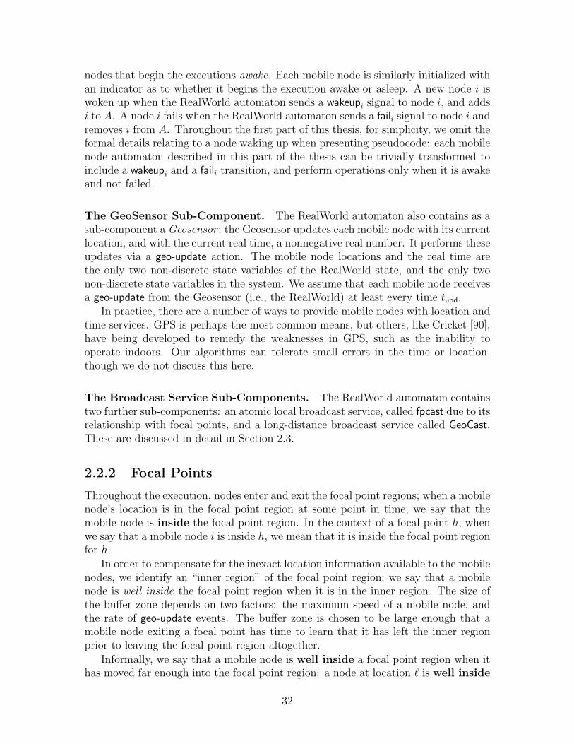
2-1 Notation used throughout Part I of this thesis. . . . . . . . . . . . . 402-2 Architecture of the theoretical system model. . . . . . . . . . . . . . 41
3-1 Virtual Object Layer. . . . . . . . . . . . . . . . . . . . . . . . . . . 44
4-1 Diagram of the Virtual Object Emulator. . . . . . . . . . . . . . . . 594-2 Automaton VOE-Client: Signature and State. . . . . . . . . . . . . 604-3 Automaton VOE-Client: Transitions. . . . . . . . . . . . . . . . . . 614-4 Automaton VOE-Server: Signature and State . . . . . . . . . . . . 634-5 Automaton VOE-Server: Input Transitions . . . . . . . . . . . . . . 644-6 Automaton VOE-Server: Internal and Output Transitions . . . . . . 65
5-1 Diagram of the Virtual Node Emulator. . . . . . . . . . . . . . . . . 835-2 Automaton VNE-Client: Signature and State. . . . . . . . . . . . . 855-3 Automaton VNE-Client: Transitions. . . . . . . . . . . . . . . . . . 865-4 Automaton VNE-Server: Signature and State . . . . . . . . . . . . 875-5 Automaton VNE-Server: Input Transitions . . . . . . . . . . . . . . 885-6 Automaton VNE-Server: Internal Transitions . . . . . . . . . . . . . 895-7 Automaton VNE-Server: Output Transitions . . . . . . . . . . . . . 905-8 Construction of Virtual Node Execution . . . . . . . . . . . . . . . 975-9 Defining Partial executions . . . . . . . . . . . . . . . . . . . . . . . 101
6-1 Implementing read/write memory in the Virtual Object Layer. . . . 1166-2 Clusters of focal points. . . . . . . . . . . . . . . . . . . . . . . . . . 1196-3 Definition of the put/get variable type τ . . . . . . . . . . . . . . . . 1216-4 Operation Manager Automaton: Signature and State . . . . . . . . 1226-5 Operation Manager invoke Transitions . . . . . . . . . . . . . . . . 1236-6 Operation Manager respond Transitions . . . . . . . . . . . . . . . . 1246-7 Operation Manager Client Transitions . . . . . . . . . . . . . . . . . 1456-8 Operation Manager Client Transitions . . . . . . . . . . . . . . . . . 146
7-1 Automaton fpcast. . . . . . . . . . . . . . . . . . . . . . . . . . . . 150
8-1 A schema for transforming a synchronous automaton into a process. 1678-2 An example process. . . . . . . . . . . . . . . . . . . . . . . . . . . 1698-3 Automaton canonicalCM: Canonical Contention Manager . . . . . . 1748-4 Automaton Bcast: State, Signature, and Trajectories . . . . . . . . 175
11

8-5 Automaton Bcast: Transitions . . . . . . . . . . . . . . . . . . . . . 1768-6 Example illustrating the timing of events in a round. . . . . . . . . 2008-7 An example instantiation of the basic system. . . . . . . . . . . . . 201
9-1 A virtual infrastructure system. . . . . . . . . . . . . . . . . . . . . 2049-2 Virtual Infrastructure Example: Automaton VI . . . . . . . . . . . . 2099-3 Virtual Infrastructure Example: Automaton client . . . . . . . . . . 2109-4 An overview of the emulator system. . . . . . . . . . . . . . . . . . 216
10-1 Indication of how a node responds to collisions. . . . . . . . . . . . 22810-2 Virtual Node Emulator — Signature and Data Structures . . . . . . 23210-3 Detailed view of a process in the emulator system. . . . . . . . . . . 23310-4 Virtual Node Emulator 1 — Delivering Messages . . . . . . . . . . . 23910-5 Virtual Node Emulator 2 — Message Protocol . . . . . . . . . . . . 24010-6 Virtual Node Emulator 3 — Scheduled Agreement Instance A . . . 24110-7 Virtual Node Emulator 3 — Scheduled Agreement Instance B . . . 24210-8 Virtual Node Emulator 4 — Unscheduled Agreement Instance . . . 24310-9 Virtual Node Emulator 5 — Join Protocol . . . . . . . . . . . . . . 24410-10 Virtual Node Emulator 6 — calculate-status function . . . . . . . . . 24510-11 Virtual Node Emulator 7 — calculate-state function . . . . . . . . . 24610-12 Virtual Node Emulator 8 — do-bcast and do-recv functions . . . . . 24710-13 Multiplexer Automaton . . . . . . . . . . . . . . . . . . . . . . . . . 248
11-1 Initialization of γv. . . . . . . . . . . . . . . . . . . . . . . . . . . . 35111-2 Construction of execution γv. . . . . . . . . . . . . . . . . . . . . . . 35211-3 Constructing the Virtual Contention Manager Execution. . . . . . . 35611-4 Constructing the Client Contention Manager Executions. . . . . . . 35911-5 Constructing the Virtual Collision Detector Rule. . . . . . . . . . . 378
12-1 Two screenshots from the Virtual Traffic Light demo. . . . . . . . . 42812-2 Virtual Traffic Light: Virtual Node and Client Routines . . . . . . . 429
A-1 Read/Write Sequential Specification. . . . . . . . . . . . . . . . . . 450A-2 Canonical Atomic Object Specification . . . . . . . . . . . . . . . . 451A-3 Abstract Read/Write Object . . . . . . . . . . . . . . . . . . . . . . 452
12

Chapter 1
Introduction
There are several significant challenges associated with developing algorithms for adhoc networks. First, the devices are unreliable: the physical hardware is often smalland fragile; the batteries are easily exhausted; users may interrupt ongoing protocolsby turning devices off. Second, the devices are often mobile, moving in an unpre-dictable manner, leaving the algorithm designer uncertain as to which devices maybe participating in which protocols. Third, communication is unreliable: the devicescommunicate using wireless radios that make use of a shared spectrum that is subjectto message collisions and other forms of interference. All of these challenges can belessened by the deployment of a fixed infrastructure that is more reliable, less mobile,and supports more efficient communication. Unfortunately, it is often impractical—due to logistical or cost-related concerns—to deploy such a fixed infrastructure.
In this thesis we develop a set of algorithms that address the unpredictable andunreliable behavior exhibited by wireless ad hoc networks. These new algorithms,together with the new techniques and abstractions introduced in this thesis, simplifythe design of algorithms for wireless ad hoc networks. Collectively, we refer to theseabstractions and the algorithms that implement them as virtual infrastructure. Vir-tual infrastructure (VI) replaces the fixed infrastructure found in more traditionalnetworks, thus compensating for unpredictable and unreliable behavior.
1.1 Ad Hoc Networks and Mobile Devices
Throughout this thesis, we focus on developing algorithms for ad hoc networks con-sisting of a large number of small, often mobile, devices that are deployed in anentirely ad hoc manner over some geographic region. These devices may be sensors,such as the Berkeley motes (see e.g., [87]), which are primarily static devices designedto collect and process data. Alternatively, these devices may be more mobile, such ashandheld PDAS or cell phones.
All of these devices, however, share certain attributes. First, the devices are smalland battery powered, and tend to be fault prone. Second, they tend to be deployed inan ad hoc manner: sensor networks are often deployed through random distribution,as from an airplane, rather than through careful placement; handheld devices tend
13

to travel with their owners, rather than as designated by an algorithm designer.
Third, these devices communicate primarily using wireless radio, rather thanthrough a fixed network. Two devices can communicate only if they are geographicallynear to each other; long-distance communication requires multi-hop communication.As a result, it can be quite difficult in a network of mobile devices to ensure reliablepoint-to-point communication between devices.
Moreover, wireless communication is notoriously unreliable: messages may be lostdue to collisions, electromagnetic interference, or other network anomalies. Moreover,the collisions may be non-uniform: some devices may receive a message, while othersmay not. The devices, however, have the ability to detect collisions: when a receivermisses a message it should have received, it can detect the disruption and report acollision. (Note that the transmitter, of course, cannot tell whether its messages wasreceived or not, i.e., receives no notification of a collision.)
A final key assumption is that the devices have reliable access to a synchronizedtime source and a localization service that provides each device with its location.
1.2 Background
There are a wide variety of scenarios in which it seems more practical to equip aset of devices with radios, forming an ad hoc network, than to build a fixed networkinfrastructure. For example, firefighters in a burning building or soldiers on an enemybattlefield may need to coordinate their operations; cars on a highway may coordi-nate to provide a cooperative driving experience. In these (oft-cited) cases, it maybe prohibitively expensive to deploy a fixed infrastructure, especially when it mustbe deployed over a large area under potentially hostile conditions. By contrast, radiotransceivers are relatively cheap and easy to integrate into current devices. Unfortu-nately, it has long been recognized that a major barrier to deploying ad hoc networksis the complexity of developing algorithms in such an unpredictable environment. Inthis section, we discuss a variety of problems and protocols that arise in the contextof wireless ad hoc networks, and some of the difficulties that arise.
1.2.1 Point-to-Point Routing
In wired networks, the basis of almost every high-level protocol is an efficient andreliable point-to-point communication protocol. The TCP/IP protocol stack [13, 88,89], along with BGP routing [92], enables devices on the internet to communicatereliably with each other, despite congestion, message loss, and occasional failures.
Naturally, then, the first attempts at developing algorithms for ad hoc networksfocused on providing reliable point-to-point communication, despite the constraintsof wireless communication and the requirement of geographic proximity (see, e.g., [42,84,85,93]). Under this paradigm, applications are oblivious to the underlying wirelessnetwork; they simply send and receive messages just as in the wired internet setting,and the routing layer compensates for the unpredictable and changing network.
14

There are two fundamental problems with this approach. The first problem ispragmatic: it can be quite expensive to implement a routing layer that entirely masksthe underlying ad hoc behavior. Recall that long-distance communication can bequite expensive; if the application is entirely oblivious to the underlying network andthe underlying topology, then the resulting protocol may spend significant time andenergy sending messages needlessly across the network. If the devices themselves aremobile, the difficulty increases substantially: maintaining a routing network despiteconstant change can be expensive, if not impossible: the routing layer must contin-ually monitor the changing network and exchange information to update its routingtables. In the worst case, where dynamic change is frequent, most protocols resortto flooding every message to every node in the network. It remains an open questionwhether existing algorithms can actually scale, in practice, to large mobile networks.
The second problem with relying on reliable point-to-point communication asa basis for ad hoc network protocols is philosophical: for many of the scenariosin which ad hoc networking appears useful, point-to-point routing is not the mostuseful or desirable form of communication. In particular, many of the applicationsfor ad hoc networks are deeply rooted in geography, while point-to-point routingis oblivious to real geography. For example, when coordinating rescue workers, itis often important to coordinate reliably with nearby devices; moreover, accuratelyand efficiently locating individuals may be critical; and certain standing orders ordanger warnings may be associated with a given location. None of these problemscan be solved simply with a location-oblivious routing protocol. By contrast, wirelesscommunication hardware is well-suited for this style of multicast communication.Protocols that focus on point-to-point communication often mask this useful capacity.
1.2.2 Wireless-Aware and Location-Aware
In response to these problems, many researchers began to focus instead on wireless-aware and location-aware algorithms. Instead of designing a protocol that uses point-to-point routing as a building block, a wireless-aware protocol is built directly on awireless MAC layer and can take advantage of the underlying network topology andwireless capabilities. There have been a variety of approaches to building wireless-aware applications, mostly varying in the properties of the underlying MAC layer.For example, Kuhn et al. describe a protocol for clustering in a static network basedon minimal MAC layer assumptions [55]. By contrast, Malpani et al. and Walter etal. present protocols for leader election [74] and mutual exclusion [102] (respectively)in a model with reliable communication, but changing topologies. The main difficultywith the wireless-aware approach is the complexity of the resulting algorithms. Inmany cases, it is nearly impossible to analyze the algorithms in a truly dynamic mobileenvironment. Even for static networks, analysis may be quite difficult: for example,many depend on complicated backoff protocols (to reduce contention on the wirelesschannels); each protocol requires a new (and often complicated) analysis. Finally, theclose dependence on MAC layer attributes may lead to difficulties and inefficiencies asMAC layers and radio technologies evolve. For example, many protocols assume thatmessage loss is relatively uniform (see, e.g., [10, 21, 22]), but that detecting collisions
15

is impossible. More recent research has indicated instead that message loss is notuniform, but that current MAC layers can in fact detect collision.
An alternative approach is to develop primitive building blocks that are wireless-aware, in contrast to point-to-point routing, which is location-oblivious. These prim-itives can then be themselves used to construct higher-level applications. Many ofthese building-block protocols take advantage of location information to simplify prob-lems of coordination and communication. One of the most common wireless-awareand location-aware primitives is geocast, the geographic analogue to point-to-pointrouting: a geocast service delivers a message to a location, rather than to a specificdevice; any device near to the target location receives the message. A variety of proto-cols for geocast have been developed, analyzed, and simulated (see, e.g., [17,50,56,78]).
A second class of wireless-aware primitives provides location-based storage (see,e.g., [65,91]). These protocols use locations as a repository for data, allowing nodes toshare data at known locations. In contrast to the algorithms presented in this thesis,however, these algorithms make only ad hoc attempts at guaranteeing reliability whendevices fail or move. The PersistentNode abstraction by Beal [11, 12] also builds adata-storage primitive. A PersistentNode is a virtual entity that travels around astatic (rather than mobile) sensor network. It can carry with it some state, but doesnot provide any consistency guarantees with respect to the data being stored.
Luo et al. attempt a more general approach to building an abstraction layer ofwireless-aware services [68]. In Nascent, they develop a suite of middleware services,including token circulation, leader election, and reliable broadcast. These services arethen made available to build higher level applications. Others, such as Greenstein etal. [39], have also attempted to develop a general toolkit for developing algorithmsfor ad hoc networks.
1.3 Virtual Infrastructure
In this thesis, we introduce a new approach to the problem of building wireless-awareand location-aware algorithms: instead of developing a specific service or applica-tion, we suggest the use of virtual infrastructure as a general abstraction. Virtualinfrastructure provides many of the advantages of a fixed infrastructure, in termsof simplicity and algorithm development, while simultaneously tolerating an ad hoc,potentially hostile, environment in which fixed infrastructure may be overly costlyand impractical. In this thesis we describe two types of virtual infrastructure: virtualobjects and virtual nodes.
1.3.1 Virtual Objects
The most basic type of virtual infrastructure introduced in this thesis consists ofvirtual objects. A virtual object is akin to a reliable storage unit deposited at someknown location in the network. Each real node, i.e., client, can store and retrieveinformation from the virtual object. The object can implement any “variable type,”and supports atomic invoke/response semantics (see, e.g., [70], Chapter 9).
16
A virtual object is (relatively) reliable, even though the set of real nodes thatreside near—and implement—the object may be continuously changing. As long assome real nodes reside near the virtual object, it can continue to operate1. Virtualobjects generalize some of the previously mentioned approaches for location-awaredata storage [11,12,65,91], and were first introduced in [32,33].
1.3.2 Virtual Nodes
A virtual node is a natural extension of a virtual object. Instead of simply storingdata and passively responding to requests, the virtual node can process data, sendmessages, and initiate actions. A virtual node resembles a reliable server, that is, apiece of computing infrastructure residing at some well-known location. Clients cansend and receive messages to and from the virtual node, just as they would interactwith a real device. If they are near to the virtual node, they may communicate withit via “local broadcast” communication; if the virtual node is farther away, they maycommunicate using a GeoCast service. Similarly, the virtual nodes may communicatewith each other. Each virtual node is an arbitrary I/O automaton [70] (without tasksor fairness), and thus can execute any arbitrary (untimed) program.
Much like virtual objects, virtual nodes are designed to be more reliable thanthe individual mobile nodes in the underlying network. As long as some real nodesreside near the virtual node, it can continue to operate. If a virtual node fails (due toregional depopulation, say), it can recover if mobile nodes again return to the regionnear to the virtual node.
Moreover, a virtual node may be mobile, traveling on a predictable path throughthe network. The basic idea of executing algorithms on virtual mobile nodes (in con-trast to static virtual infrastructure) was inspired by the development of compulsoryprotocols [20, 40, 66], and was first introduced in [31]. The basic observation in com-pulsory protocols is that if mobile nodes moved in a programmable way, algorithmscould take advantage of the motion, providing elegant and simple solutions. This ideais illustrated by Hatzis et al. [40], who introduce the notion of a compulsory protocol,one that requires a subset of the mobile nodes to move in a pre-specified manner.They present an efficient compulsory protocol for leader election. The routing pro-tocols of Chatzigiannakis et al. [20] and Li et al. [66] provide further evidence thatcompulsory protocols are simple and efficient. Using virtual mobile nodes, it is possi-ble to take advantage of compulsory protocols even in networks where the underlyingmobile nodes in fact do not behave in the desired manner.
1.4 Implementing Virtual Infrastructure
In this thesis we present three different algorithms for implementing virtual infras-tructure. The first two of these algorithms are designed for a network that guarantees
1As presented in this thesis, there is no mechanism for virtual objects to recover; the sametechniques that are employed to support the recover of virtual nodes, however, can be adopted forvirtual objects.
17
reliable communication: the first implements virtual objects, and the second virtualnodes. The third algorithm is designed for a network in which communication isunreliable, that is, susceptible to collisions and lost messages.
All the algorithms in this thesis for implementing virtual infrastructure are, fun-damentally, based on replicated state machine techniques. Each virtual infrastructurecomponent is implemented by a set of participants (replicas) that maintain the stateof the virtual infrastructure component. Whenever the state is updated, as a result ofeither a message received or a spontaneous action, all the replicas perform a consistentupdate, maintaining the replicated state.
The main challenges lie in dynamically determining an appropriate set of replicasas the underlying system changes, ensuring consistency even as the set of replicas iscontinuously changing, and ensuring that the resulting emulation is efficient.
Each virtual infrastructure component is emulated by a set of replicas that residenear the actual location of the virtual object or node. As real devices move towardand away from the virtual component, and as real devices join and leave the system,the set of replicas changes continuously. In particular, a device is able to examineits current location and determine whether to join or leave the emulation; the use ofhysteresis may well improve efficiency.
In order to maintain consistency, each replica must apply updates in the sameorder. One way to achieve this is to use a (local) totally ordered broadcast servicethat ensures that messages sent within a specific region—the area of emulation of thevirtual component—are delivered in the same order to all active participants. Whenthe network guarantees reliable and timely communication, it is possible to build atotally ordered communication service using timestamp-based techniques originallydeveloped by Lamport [58] in the context of fixed-infrastructure replicated state ma-chines. When a node joins the emulation, it first requests a copy of the replicatedstate, and at the same time begins participation in the totally ordered broadcastservice. On receiving a copy of the replicated state, the new node can update thestate (adjusting for changes that may have occurred while the replica message was intransit) and begin participating in the emulation. In Part I of this thesis, we presentprotocols to implement virtual infrastructure based on these ideas.
Unfortunately, collisions and message loss may disrupt communication, making itdifficult to implement totally ordered broadcast. In particular, the timestamp-basedtechniques for totally ordering messages do not adapt well to such an environmentsince it is difficult to determine when everyone has received a particular message. Mostother prior techniques for implementing replicated-state machines, such as Paxos [60],also do not adapt well to a wireless environment. For example, many require all theparticipants to communicate. In a wireless setting, however, increased communicationresults in increased rates of collision; in such a setting, Paxos might never terminate.
Thus, in Part II of this thesis, we focus on the problem of implementing vir-tual infrastructure in collision-prone wireless networks. The protocol is based ona two-round consensus protocol in which all the replicas agree on each update tothe replicated state. However, if consensus is used directly as a building block, theresulting replicated-state machine protocol is not suitable for implementing virtualinfrastructure. In particular, the resulting emulation is not efficient: it results in mes-
18
sages that may be arbitrarily large, and there may be long delays in implementingeven a single step of the virtual infrastructure component.
We therefore introduce a special type of replicated-state machine that is collision-aware and suitable for implementing virtual infrastructure. Instead of simply repeat-ing the consensus algorithm for each step of the state machine, it adapts the basicconsensus algorithm ideas to develop a more efficient protocol that guarantees efficientvirtual nodes and efficient communication.
1.4.1 Performance
Virtual infrastructure is of course only useful when the virtual components performefficiently and with low latency. For each algorithm implementing virtual infrastruc-ture, this thesis analyzes the conditional performance.
The first two algorithms for implementing virtual infrastructure guarantee goodperformance under the assumption that the underlying physical network is well-behaved, e.g., it delivers messages within a bounded time. By good performance,we mean that each action taken by a virtual object or virtual node (e.g., sending orreceiving a message) is emulated in only a small constant number of message delays.
The third algorithm for implementing virtual infrastructure (presented in Part IIof this thesis) guarantees good performance if the underlying network is eventuallywell-behaved. In contrast to Part I, the second part of this thesis assumes a syn-chronous but unreliable broadcast service. If, eventually, messages are deliveredreliably (and other stabilization criteria hold) in the underlying network, then thevirtual infrastructure guarantees that eventually the virtual network is also well-behaved: messages are delivered reliably and other good criteria hold. Moreover, theimplementation itself is efficient, requiring only a constant number of rounds of com-munication and constant-sized message-overhead to implement each virtual round.
1.5 Overview of the Thesis
The thesis is divided into two main parts. The first part of the thesis focuses onintroducing the concept of virtual infrastructure in the context of reliable commu-nication, while deferring many of the details related to collisions and message loss.The second part focuses on the more practical problem of designing and developingvirtual infrastructure in real, collision-prone, ad hoc networks.
Part I
In the first part of the thesis, we assume that the mobile nodes can communicatereliably. Thus, Part I focuses on the other two major problems of ad hoc networks:fault-prone devices and unpredictable motion. The third problem, unreliable com-munication, is postponed to the second part of the thesis. By avoiding the problemsof unreliable communication, Part I allows for an introduction to the basic ideas of
19

virtual infrastructure, and allows a simple presentation of algorithms that containmany of the major ideas used in Part II of the thesis.
Chapter 2. We begin by introducing a model of mobile ad hoc networks, a variationon the commonly used “unit-disc graph” model for wireless networks. Communicationis either local (via a local broadcast service) or long-distance, via a GeoCast service.We discuss in this chapter some of the existing GeoCast protocols that may be usedto implement this service. An alternate model that does not include long-distanceGeoCast is discussed in Chapter 7.
Chapter 3. We then define the two main types of virtual infrastructure: the VirtualObject Model and the Virtual Node Model.
Chapter 4. In this chapter, we present a protocol that implements the Virtual Ob-ject Model in a mobile ad hoc network. This protocol, the Virtual Object Emulator,takes advantage of “focal points” where mobile nodes congregate to implement virtualobjects. We argue that the protocol correctly emulates the Virtual Object Model,and we present a brief analysis of the efficiency of the Virtual Object Emulator.
Chapter 5. Next, we consider the Virtual Node Model. I extend the Virtual Ob-ject Emulator, developing a protocol that implements the Virtual Node Model. TheVirtual Node Emulator is quite similar conceptually to the Virtual Object Emulator.The analysis, however, is more involved as the virtual entities being emulated aremore powerful: virtual nodes can initiate actions on their own, and they can commu-nicate directly with each other. We argue that the protocol correctly emulates theVirtual Node Model, and we present a brief analysis of the efficiency of the VirtualNode Emulator.
Chapter 6. In this chapter, we describe an application that can be implementedusing the Virtual Object Model: a reliable, reconfigurable read/write shared memory.This application is built using virtual objects, which store the data and ensure thereliability and availability of the shared memory. This chapter serves as an exampleof how virtual infrastructure can be used to simplify the development of otherwisecomplicated applications. In particular, it is relatively simple to understand the be-havior of the protocol, which would otherwise be complicated by analyses of mobilityand failure rates.
Chapter 7. We conclude Part I with a discussion of how to modify the proto-cols described in the preceding chapters to use only local communication. The basicmodel introduced in Chapter 2 allowed for both some local communication (“fpcast”)and long-distance communication (GeoCast). In practice, wireless networks typicallycontain only simple local broadcast. (In fact, one of the potentially compelling ap-plications of virtual infrastructure is to build reliable long-distance communication.)Thus, in this section we describe a virtual node-based infrastructure that supports
20

only local communication, and describe how the protocol described in Chapter 5 canbe modified to execute in an environment with only local communication.
Part II
In the second part of the thesis, we focus on the problem of implementing virtualinfrastructure in wireless networks with unreliable communication. In general, thispart is based on many of the ideas originally introduced in Part I; however, unreliablecommunication, collisions, and lost messages introduce a variety of complications thatrequire some new techniques and new approaches.
Chapter 8. We begin the second part by presenting a more realistic model forwireless networks. The new model captures many attributes of real networks, such as(i) non-uniform patterns of message loss where different nodes receive different sets ofmessages; (ii) collision detection, which allows devices to detect anomalies in receivingmessages; and (iii) reliable time and synchronous communication, which allows nodesto execute algorithms in synchronous rounds. We assume that the collision detectorsare complete, meaning that they detect all collisions, and eventually accurate, meaningthat, eventually, they report no false positives. The new model also provides deviceswith contention managers, which use backoff protocols to reduce the contention onwireless channels. Unlike in Part I, all communication is local.
Chapter 9. Next, we introduce a virtual node-based infrastructure that is compat-ible with a collision-prone network. In particular, the virtual infrastructure modelintroduced in this chapter reproduces many of the properties of the underlying wire-less network: communication is local, and occurs in synchronous rounds, clients andvirtual nodes can detect collisions, and both clients and virtual nodes have access tocontention managers which can help to reduce the number of collisions.
Chapter 10. In this chapter, we present an algorithm that implements the virtualinfrastructure model described in Chapter 9. Much like the emulator protocols inPart I, this algorithm is based on a replicated-state-machine approach. However,unlike Part I, this replicated state machine is collision aware, in that it can toleratecollisions and cooperate with a contention manager to reduce collisions.
At the heart of the emulator is a three-phase “agreement protocol” in which thereplicas for each virtual node try to agree on an execution of that virtual node. This“agreement protocol” is derived from an earlier consensus protocol for wireless net-works [23, 79], and is reminiscent in style of a three-phase-commit protocol. Unlikethese earlier protocols, however, the “agreement protocol” does not always resultin the replicas coming to single decision; disagreement is (inevitably) a possible out-come. It does guarantee, however, that when the network is well-behaved, the replicasagree; moreover, it ensures that the disagreement is limited such that the replicas canconverge eventually on a single virtual node execution.
21

Chapter 11. We then proceed to argue that the protocol presented in Chapter 10is a correct implementation of the virtual infrastructure layer. The main goal of thechapter is to transform an arbitrary execution α of the underlying (physical) systeminto an execution γ of the virtual infrastructure such that the clients cannot distin-guish between α and γ. This indistinguishability property implies that, from theclients’ perspective, the emulator is successfully implementing the virtual infrastruc-ture. The proof proceeds by first constructing an execution of each of the clients andvirtual nodes, along with the other components of the virtual system, and then past-ing the executions together to produce a unified execution γ. The main difficulty isin constructing the individual virtual node executions in such a way that they satisfythe requisite properties.
1.6 Related Work
In this section, we discuss some of the other work related to the ideas presented inthis thesis. We begin in Section 1.6.1 with a review of the progress that has been inthe area of virtual infrastructure. Next, in Section 1.6.2, we review other abstrac-tions for ad hoc networks. In Section 1.6.3, we describe prior research on replicatedstate machines, the key algorithmic tool in implementing virtual infrastructure. Fi-nally, in Section 1.6.4, we present some background on radio networks and wirelesscommunication.
1.6.1 Virtual Infrastructure
We first introduced the idea of virtual infrastructure in [32] in the context of virtualobjects that are used to implement a reconfigurable, atomic memory. This paperwas then extended in [33] to support general virtual objects. The protocol for vir-tual objects in Chapter 4 is derived from this paper, as is the example applicationin Chapter 6.
We extended the virtual infrastructure paradigm to include virtual nodes in [31].The protocol in [31] extends the ideas in [32], and also introduces the idea of a mobilevirtual entity. The protocol in Chapter 5 is derived from [31], as is the material inChapter 7 on implementing virtual infrastructure in the context of local-only com-munication. This paper also introduced the idea that a virtual node might recover,even if it had failed (due to an insufficient number of replicas).
In [34], we introduce the idea of autonomous virtual nodes, that is, virtual nodesthat determine their motion in an on-line fashion in response to ongoing sensing andcomputation. For example, an autonomous virtual node may choose to move itselftoward a more populated region of the network, rather than languishing in a desertedcorner of the world. Unlike other virtual node models, the autonomous virtual nodemoves discretely, where each move follows from a discrete programmatic output. Theypresent an overview of a self-stabilizing protocol to implement this new virtual nodelayer, focusing on the difficulties in ensuring consistent membership in the context ofan unpredictable virtual location. They also introduce new techniques for restoring
22

a failed virtual node. In particular, a key difficulty is determining when the virtualnode has failed and needs to be recreated. They present three different techniques,one based on a network of static virtual nodes and two based on random-walk basedtechniques.
In [29,30], we introduce a timed virtual infrastructure in which the virtual nodesrepresent timed I/O automata (TIOA). They present a self-stabilizing algorithm forimplementing this virtual infrastructure model. They also describe how to implementa tracking service and a GeoCast routing service, which together instantiate a point-to-point routing service. More details on tracking can be found in [83], and moredetails on routing can be found in [35].
Tulone [99] extends [31], studying the restrictions on mobility necessary to ensurethat a sufficient number of virtual nodes remain active, and developing robust quorumsystems that allow for virtual nodes to restore their previous state after a failure.
Lynch et al. [69] develop a particularly interesting application of virtual infrastruc-ture. They use virtual nodes to coordinate the motion of the clients in the system.The resulting protocol enables the mobile nodes to easily and efficiently form anyparticular geometric pattern in the plane, despite unreliable failures. Brown [15] hascontinued this direction, using a virtual infrastructure to construct an air-traffic con-trol system in which virtual nodes act to coordinate the motion of airplanes. Brownfocuses on the problem of free flight, where the individual airplanes can choose theirown flight paths independently.
Brown et al. [14] have implemented a prototype virtual infrastructure on a setof handheld Compaq iPAQ devices. The protocol used in [14] is a simplified—andoptimized—variant of the algorithm described in Chapter 5 and [31], including themodifications described in Chapter 7 (and first introduced in [31]). Using this pro-totype virtual infrastructure, we built a few simple applications, including a virtualtraffic light that can be used to coordinate traffic at a busy intersection.
1.6.2 Other Abstractions for Ad Hoc Networks
There has been much work of late (and, in some cases, concurrently with the work inthis thesis) on high-level programming languages and region-based abstractions forad hoc networks, particularly sensor networks, e.g., [64,80,81,103,104]. Much of thiswork is complementary to the work on virtual infrastructures presented in this thesis:better programming languages are essential to simplifying the task of developingsoftware for ad hoc networks; providing reliable virtual infrastructure with strongconsistency guarantees can simplify the programming paradigm, regardless of thelanguage employed.
The work of Nath and Niculescu [77] takes advantage of precalculated paths toforward messages in dense networks. Messages are routed along trajectories, wherenodes on the path forward the messages. Similarly, prior GeoCast work (for exam-ple, [17, 78]) attempts to route data geographically. Sun et al. [98] use cars travelingon a highway to regionally broadcast alert information. In many ways, these strate-gies are ad hoc attempts to emulate some kind of traveling node. We provide a moregeneral framework to take advantage of predictably dense areas of the network to per-
23

form arbitrary computation. A significant focus of these prior papers is determininggood trajectories, a problem that we do not address.
1.6.3 Replicated State Machines
Many of the key techniques in implementing virtual infrastructure are derived fromthe literature on replicated state machines. The concept of implementing fault-tolerant services using replicated state machines (RSMs) was first introduced byLamport in [58] and extended and popularized by Schneider in [94]. Lamport [57]also presents a technique for implementing a fault-tolerant state machine in a message-passing system with fail-stop replicas (i.e., with reliable failure detection). For strongerfault models, the Paxos protocol and its variants [61–63] provide an RSM implemen-tation that is resilient to fewer than n/2 replica crashes, where n is the number ofreplicas, and that tolerates arbitrarily long periods of network instability. Castro andLiskov present a Byzantine resilient version of the Paxos protocol [19]. A separateline of research was dedicated to implementing RSMs on top of view-oriented groupcommunication systems (e.g., [5, 36,49]).
These protocols, however, were designed for traditional “wired” networks andtherefore do not address several important concerns arising in wireless ad hoc envi-ronments. In particular, they lack the ability to dynamically adapt their patterns ofcommunication to the number of participating nodes, and rely on a priori knowledgeof the number of participants and their identities. An algorithm for atomic broadcastthat tolerates dynamic networks with an unknown set of participants is presented byBar-Joseph et al. [7]. Although their protocol can be used to implement a reliablestate machine, it is nevertheless inapplicable in our setting as it assumes reliable,collision-free communication.
There has been a substantial body of prior work on developing TDMA schedulesfor wireless ad hoc networks where the number of participants is a priori unknown(e.g., [16,41]). A TDMA schedule can be used to avoid collisions, which can simplifythe problem of implementing an RSM. Note, however, that these techniques do nottrivialize the implementation of an RSM as they result in initial periods of instabilityduring which collisions may occur. Moreover, many of these algorithms are unsuitablefor highly dynamic networks.
1.6.4 Wireless Communication and Radio Networks
Starting with a seminal paper by Bar Yehuda et al. [10], and followed by many others(e.g., [9,21,53]), reliable broadcast was studied in synchronous radio networks wherea node is guaranteed to deliver a message in a given time slot if and only if exactly oneof its neighbors is transmitting a message in this slot. In contrast to this model, inthis thesis we develop a communication model that allows for unpredictable collisionpatterns which in particular, might result in non-uniform message loss. Such non-deterministic behavior is frequently observed in real networks [51, 106, 108], and infact arises in simulations [23]. We also do not assume any advance knowledge of anode’s neighbors and therefore, cannot attribute lost messages to specific nodes in
24

the networks. A variety of other variants to the reliable broadcast problem in a modelsimilar to that of [10] have been considered in [4, 22,25,76].
Current practical research in wireless devices and networks motivates the basicmodel of a wireless network developed in Part II of this thesis. First, it is wellknown that wireless broadcast networks are inherently unreliable. Several recentexperimental studies [37, 51, 105, 108] suggest that even with sophisticated collisionavoidance mechanisms (e.g., 802.11 [1], B-MAC [86], S-MAC [107], and T-MAC [101]),and even assuming low traffic loads, the fraction of messages being lost can be as highas 20− 50%.
The algorithms in Part II of this thesis rely on collision detectors to overcomeuncertainties in message loss. The importance and practicality of having collisioninformation available to applications was argued in [106]. Several existing MAC layers,such as B-MAC [86], already support some collision detection capability. Moreover,the recent study by Deng et al. [27] suggests that there is no technical obstacle toadding collision detection support to the current 802.11 protocol.
25

Part I
An Introduction toVirtual Infrastructure
26

Introduction
In the first part of this thesis, we introduce the idea of virtual infrastructure, and de-velop protocols to implement virtual infrastructure in wireless networks that supportreliable communication. Part I focuses on two of the major problems of ad hoc net-works: fault-prone devices and unpredictable motion. The third problem, unreliablecommunication, is postponed to the second part of the thesis.
We begin in Chapter 2 by introducing a model of mobile ad hoc networks. Inthis model, mobile nodes are fault-prone devices that move unpredictably in a two-dimensional plane. They communicate via various broadcast services: either local(via an fpcast service), or long-distance, via a GeoCast service ( as per, say, [17,50]).
Next, in Chapter 3, we formally introduce the idea of virtual infrastructure. Thischapter first introduces the idea of virtual objects and virtual nodes, perhaps thekey innovation in Part I of this thesis. We begin by defining the Virtual ObjectModel, a virtual infrastructure layer that resembles a typical distributed shared objectmodel. In the virtual object model, clients interact with virtual objects, invokingoperations and receiving responses. We then proceed to introduce the Virtual NodeModel. Unlike the Virtual Object Model, in which the virtual entities are restrictedto objects, the Virtual Node Model allows for the virtual entities to perform arbitrarycomputation. Communication between the “clients” and “virtual nodes” proceeds viaa virtual GeoCast service.
In Chapters 4 and 5, we present protocols to implement the Virtual Node Modeland the Virtual Object Model, respectively. Both of these protocols rely on “focalpoints,” well-populated regions of the network, to implement the virtual entities:each focal point is associated with a virtual object or virtual node, and each mobilenode in a focal point acts as a replica for the associated object. As mobile nodesarrive, leave, and fail, the set of replicas adapts to the current set of available mobilenodes. These protocols extend standard replicated-state-machine techniques to thisnew environment. We show that the two protocols are correct, and provide a briefanalysis of their efficiency.
In Chapter 6, we present an example of an application that is built on the Vir-tual Object Model. Specifically, we show how to implement a reliable, reconfigurableread/write shared memory. The virtual objects are used to replicate data throughoutthe entire world, and a reconfigurable set of quorums are used to maintain consis-tency among the virtual nodes. The protocol is based on a simplified version of theRamboprotocols (see, e.g., [38]). We argue that the the resulting shared memoryguarantees atomic read and write operations, and provide some analysis as to its
27

efficiency.Finally, in Chapter 7, we consider networks in which all communication is local.
That is, unlike in the previous chapters in Part I, there is no long-distance GeoCastservice available, and no focal-point-oriented fpcast service available. We provide abrief description of a virtual node infrastructure (based on the Virtual Node Modelintroduced in Chapter 3) in which all communication is local (in contrast to theearlier model in which communication occurs via a virtual GeoCast service). Wethen describe how to modify the protocols described in Chapter 5 to implement thislocal virtual node layer.
28

Chapter 2
Wireless Ad Hoc Network Model
In this chapter, we describe the underlying model for a mobile ad hoc network. Fig-ure 2-1 defines some of the notation used in Part I of the thesis. Figure 2-2 providesan overview of the system model.
The basic model consists of a bounded region of a two-dimensional plane, popu-lated by mobile nodes. The mobile nodes communicate using an atomic local broad-cast service, which we call fpcast, and a long-distance communication service, calledGeoCast. Each mobile node receives discrete updates from an external “Geosensor”that notifies the mobile nodes of the real time and their location in the real world.
While we make no assumptions about the motion of the mobile nodes, we doassume that certain regions are usually “populated” by mobile nodes. We assumethat there exists a finite collection of such regions in the plane, called focal points, suchthat (i) at any point during an execution, “enough” focal points remain “populated,”ensuring that sufficiently many focal points remain available, and (ii) within eachfocal point, there is a reliable, atomic broadcast service available for the mobile nodesto communicate reliably with each other. A focal point can be static, meaning thatit consists of a fixed geographic region, or a focal point can be mobile, changingthroughout an execution.
We begin in Section 2.1 to describe the basic geometry of the world, focusing onthe definition of a focal point. The definitions from this section are used later inother contexts (for example, the description of virtual objects and virtual nodes inChapter 3). In Section 2.2, we describe the mobile nodes. In Section 2.3 we describethe two broadcast service: the fpcast service and the GeoCast service. In Section 2.4,we describe the liveness properties of the basic model.
2.1 Geometric Basics
The world consists of a bounded region of a two-dimensional plane1. We assume thatthere exists a finite collection of regions in the plane, called focal points. For each
1In fact, all the results described in this thesis carry over naturally to an arbitrary metric space.It is necessary only that the metric space supports appropriate broadcast services. In particular, itwould be natural to consider three-dimensional space.
29
focal point, we identify a “focal point center,” that is, a designated location within thefocal point, and a “focal point region,” that is, a portion of the plane covered by thefocal point. A focal point can be static, meaning that it consists of a fixed geographicregion, or a focal point can be mobile, changing throughout an execution2. We assumethat the set of focal points is determined a priori and is common knowledge.
More formally, a focal point is defined by:
1. a unique identifier h chosen from the set O,
2. a function fp-regionh : R≥0 → P(L) that maps each time t to a contiguousgeographic region in the plane3, the focal point region, and
3. a function fp-centerh : R≥0 → L that maps each time t to a point within thatgeographic region, the focal point center.
Notice that a focal point is dynamic, since its center and region can change withtime. If the center and region of the focal point do not change with time, that is, ifthe two functions are constant, we say that the focal point is static and its maximumvelocity is 0.
We define the radius of a focal point at some time t in the natural way: a focalpoint h has radius r at time t if r is the infimum value such that fp-regionh(t) iscontained in a circle of radius r centered at fp-centerh(t).
Since the focal point center and region can change with time, we need to definethe velocity of a focal point. If the focal point region is “rigid” and does not rotate,then we can define the velocity simply with respect to the focal point center. Moregenerally, we can define the velocity in terms of how rapidly a point in the planeis “left behind” by the focal point region. For a dynamic focal point h ∈ O whosegeographic region is defined by the function fp-regionh(t), we define the maximumvelocity as follows:
• Define fp-regionh(t) to be the complement of fp-regionh(t), that is, all the pointsin the plane L not part of the focal point region for h at time t.
• For a point ` ∈ fp-regionh(t), define depthh(`, t) to be the infimum distancebetween the point ` and the closest point in L that is not part of the focal pointregion for h at time t. It specified how close a location ` is to the edge of thefocal point at time t.
• Define vsup(h), a real number, to be the supremum velocity of focal point h asfollows:
vsup(h) = sup
t,t′∈R≥0, t≤t′
`∈fp-regionh(t)
`/∈fp-regionh(t′)
depth(`, t)
t′ − t
2Dynamic focal points, i.e., those that chance location during an execution, are used in imple-menting virtual mobile nodes. The mobility of virtual nodes can be useful in the context of movingdata and computation through a network.
3By P(S) we refer to the power set of S, i.e., {s : s ⊆ S}.
30

Thus, the supremum velocity of a focal point h determines the minimum (in fact,infimum) length of time that it takes for some fixed point ` in a focal point regionto cease to be in that focal point region. For example, if a point is at a distance dfrom the edge of a focal point region that has a supremum velocity of vsup(h), thenthat point in the plane will remain within the focal point region for at least d/vsup(h)time.
As a specific example, consider a focal point region that is defined by a circleof some fixed radius around the focal point center. Notice that in this case, themaximum velocity of the focal point is simply the maximum velocity of the focalpoint center. Define vfp-max to be the maximum velocity vsup(h) for any h ∈ O.
2.2 Mobile Nodes
The basic model is populated by mobile nodes, each assigned a unique identifier fromthe set I. We model the computation at each mobile node as an asynchronous I/Oautomaton; an asynchronous I/O automaton is a special case of a timed I/O automa-ton in which all the state variables are discrete, and in which the set of trajectoriesconsists of all constant-valued mappings from all possible time intervals. (See Ap-pendix A for more details on timed I/O automata.) As a result, it is reasonable tocompose asynchronous automata with timed I/O automata.
The mobile nodes may join and leave the system, and may fail at any time. (Wetreat nodes leaving the system as having failed.) The mobile nodes can move on anycontinuous path in the plane, with speed bounded by a constant vmax. We assumethere exists at least one node i0 ∈ I.
In the following two subsections, we discuss the mobile nodes’ interactions withtheir environment (Section 2.2.1), and their interactions with the regions of the worldidentified as focal points (Section 2.2.2).
2.2.1 The Real World
We model the environment, which interacts with the mobile nodes, using a timedRealWorld automaton (see [45, 71, 72] for a formal presentation of timed automata;see Appendix A for a brief review). The RealWorld automaton maintains in itsstate the current location of every mobile node, as well as the current real time.It also maintains the failure status of each mobile node. Finally, the RealWorldimplements the various broadcast services that the mobile nodes use to communicate.We occasionally refer to these different functionalities of the RealWorld as “sub-components.” (Notice that sub-components are not distinct automata, that is, theyare not automata that can be composed to form the RealWorld.)
The Status Sub-Component. In order to model nodes joining and leaving thesystem, the RealWorld automaton maintains in its state an indication for each mobilenode as to its status, i.e., whether it is asleep, awake or failed. Formally, when theexecution begins, the RealWorld automaton is initialized with a set A ⊆ I of mobile
31
nodes that begin the executions awake. Each mobile node is similarly initialized withan indicator as to whether it begins the execution awake or asleep. A new node i iswoken up when the RealWorld automaton sends a wakeupi signal to node i, and addsi to A. A node i fails when the RealWorld automaton sends a faili signal to node i andremoves i from A. Throughout the first part of this thesis, for simplicity, we omit theformal details relating to a node waking up when presenting pseudocode: each mobilenode automaton described in this part of the thesis can be trivially transformed toinclude a wakeupi and a faili transition, and perform operations only when it is awakeand not failed.
The GeoSensor Sub-Component. The RealWorld automaton also contains as asub-component a Geosensor ; the Geosensor updates each mobile node with its currentlocation, and with the current real time, a nonnegative real number. It performs theseupdates via a geo-update action. The mobile node locations and the real time arethe only two non-discrete state variables of the RealWorld state, and the only twonon-discrete state variables in the system. We assume that each mobile node receivesa geo-update from the Geosensor (i.e., the RealWorld) at least every time tupd.
In practice, there are a number of ways to provide mobile nodes with location andtime services. GPS is perhaps the most common means, but others, like Cricket [90],have being developed to remedy the weaknesses in GPS, such as the inability tooperate indoors. Our algorithms can tolerate small errors in the time or location,though we do not discuss this here.
The Broadcast Service Sub-Components. The RealWorld automaton containstwo further sub-components: an atomic local broadcast service, called fpcast due to itsrelationship with focal points, and a long-distance broadcast service called GeoCast.These are discussed in detail in Section 2.3.
2.2.2 Focal Points
Throughout the execution, nodes enter and exit the focal point regions; when a mobilenode’s location is in the focal point region at some point in time, we say that themobile node is inside the focal point region. In the context of a focal point h, whenwe say that a mobile node i is inside h, we mean that it is inside the focal point regionfor h.
In order to compensate for the inexact location information available to the mobilenodes, we identify an “inner region” of the focal point region; we say that a mobilenode is well inside the focal point region when it is in the inner region. The size ofthe buffer zone depends on two factors: the maximum speed of a mobile node, andthe rate of geo-update events. The buffer zone is chosen to be large enough that amobile node exiting a focal point has time to learn that it has left the inner regionprior to leaving the focal point region altogether.
Informally, we say that a mobile node is well inside a focal point region when ithas moved far enough into the focal point region: a node at location ` is well inside
32

a focal point at time t if:
depth(`, t) > tupd · (vmax + vfp-max) . (2.1)
We refer to the locations ` that satisfy Equation 2.1 at time t to be the inner regionof h at time t. In the context of a focal point h, when we say that a mobile node i iswell inside h, we mean that it is well inside the focal point region for h.
Notice that according to this definition, if a node is well inside a focal point regionat some time t, then during the most recent geo-update prior to time t the node learnsthat it is, in fact, inside the focal point region. Conversely, if a node is not inside afocal point region at time t, we can be certain that during the most recent geo-updateprior to time t, the node learns that it is, in fact, not well inside the focal pointregion. (Note the contrast between inside and well inside in the previous claim.) Wethus conclude the following:
Lemma 2.2.1. Let α be any finite execution, let i ∈ I be a mobile node, and leth ∈ O be a focal point.
• If i is well inside h at the end of α, and if geo-update(`, t)i is the last geo-updatei
event in α, then i is inside the focal point region of h at time t.
• If geo-update(`, t)i is the last geo-updatei event in α, and if i is well inside h attime t, then mobile node i is inside the focal point region of h at the end of α.
Proof. Consider the first claim. Since the geo-update occurs at most time tupd priorto the end of α, the relative distance travelled by the mobile node with respect tothe focal point region during this interval of time is at most tupd · (vmax + vfp-max) (bythe definition of vfp-max). Since i is well inside h, the depth in the focal point regionis larger than this distance, and hence i is inside the focal point region at time t.
Next, consider the second claim. Again, since the geo-update occurs at most timetupd prior to the end of α, the relative distance travelled by the mobile node withrespect to the focal point region during this interval of time is at most tupd · (vmax +vfp-max) (by the definition of vfp-max). Since i is well inside h at time t, the depth inthe focal point region is larger than this distance, and hence i is inside the focal pointregion at the end of α.
In Chapters 4 and 5, we present protocols that take specific actions when a mobilenode is well inside a focal point, according to its most recent geo-update. Lemma 2.2.1allows us to conclude that whenever a mobile node takes such an action, it is in factinside a focal point.
2.2.3 Motion-Controlled Devices
Throughout this section, we have assumed that the mobile nodes have no control overtheir own motion. In some practical situations, however, there may be an algorithmrunning on the mobile node that controls the physical motion of the device. Forexample, a mobile robot can direct its own motion in a suitable fashion; a vehicle
33

may choose its own velocity; machines in a factory may have some autonomous controlover their actions.
Moreover, some of the most compelling uses for the virtual infrastructure paradigmpresented in this thesis are those in which devices may have some control over theirmotion. For example, consider a battlefield scenario where a set of tanks wish tocoordinate their motion according to some predetermined formation; in this case, thetanks might use virtual nodes to coordinate their motion. (See [69] for an exampleof using virtual infrastructure to solve a basic coordination problem among mobilerobots.)
It is straightforward to augment the model presented here to include motion con-trol. Specifically, each mobile node is assumed to produce (as an output) some motioncontrol signal, for example, move(. . .). This signal may be in the form of a velocityvector, a target waypoint, or any other desired form of motion control signal. Inpractice, the most common such signal is acceleration. The RealWorld automaton, asa model of the environment, receives such signals as input and uses them to updatethe location of the mobile nodes.
2.3 Broadcast Services
In the first part of this thesis, we assume the availability of reliable communicationservices. (We relax the assumption of reliability in the second part of this thesis.)There are two different types of broadcast services that the mobile nodes use tocommunicate:
• fpcasth, for each h ∈ O: a focal point broadcast service that supports reliable,totally-ordered communication among nodes in focal point h; each messagebroadcast is delivered eventually to every mobile node in the focal point regionfor h, and each node receives the messages in the same order.
• geocast: a long-range broadcast service that delivers messages to specified lo-cations in the network; each message broadcast is eventually received by everynode that is within some radius R of the designated destination location.
The first broadcast service, fpcast, is “local” in that, conceptually, it operates overa small region of the network, delivering messages to nearby nodes4. The secondservice, GeoCast, handles multi-hop message delivery: it can deliver a message fromany location in the network to any other location in the network. Unlike a moretraditional routing service, however, it delivers messages to a given location in thenetwork, not to a given mobile node. In Chapter 7, we discuss how to implementvirtual infrastructure when only local broadcast is available.
4While a focal point region could theoretically be quite large, we tend to think of a focal pointregion as a single-hop region of the network. Implementing the fpcast service over a multi-hop focalpoint region is presumably more difficult, leading to the conclusion that focal point regions are likelyto be small.
34

Formally, the broadcast services are sub-components of the RealWorld automatonthat models the external environment. For each broadcast service, we specify boththe safety and liveness properties guaranteed by traces of the RealWorld automaton.
2.3.1 The fpcast Service
For each focal point, we assume that there is a broadcast service that guaranteesreliable, totally-ordered local communication between mobile nodes within that fo-cal point. The broadcast services guarantees the following properties: (1) integrity,meaning that every message delivered was previous broadcast; (2) reliable delivery,meaning that if two correct nodes reside in some focal point, and one sends a mes-sage, then it will eventually be delivered to the other; (3) total order, meaning thatmessages are delivered to all of the mobile nodes in the same order; and (4) consistentdelivery, meaning that if a mobile node remains in a focal point for some period oftime, there will be no “gaps” (with respect to the ordering) in the sequence of mes-sages received by the mobile node. The service is defined here as “asynchronous,”meaning that there is no bound on the delivery time for messages. Formally, thismeans that for every message broadcast, there is some ε that bounds the latencyof the message. Later in Section 2.4, when making further assumptions as to theperformance of the system, we assume that this message delay is bounded.
Formal Definition. The broadcast service for focal point h ∈ O, fpcasth, supportsthe following interface for each mobile node i:
• Input fpcast(m)h,i
• Output fpcast-rcv(m)h,i
where m is an arbitrary message to be sent. Notice that the first index of the actionindicates the focal point; the second index indicates the mobile node at which theevent takes place. For mobile nodes that are in focal point h, the fpcasth servicesatisfies the following properties:
Integrity : For any message m and mobile node i, if an fpcast-rcv(m)h,i event occurs,then an fpcast(m)h,j event precedes it, for some mobile node j.
Reliable Delivery : For each fpcast(m)h,i event there exists some ε such that: as-sume that i is inside the focal point region for h when the event occurs, andassume that mobile node j ∈ I (potentially j = i) is a mobile node satisfyingthe following:
• mobile node j is in the focal point region for h when the event occurs;
• mobile node j remains in focal point region until time ε after the event;and
• mobile node j does not fail until at least time ε after the event;
35

then an fpcast-rcv(m)h,j event occurs within time ε after the event, deliveringthe message m to node j.
Total Order : For every execution, if every message sent by the fpcasth is unique5,then there exists a total ordering m1, . . . ,mk, . . . of all messages sent by thefpcasth service during an execution; if some mobile node i receives messages mr
and mt, then i receives mr prior to mt if and only if r < t.6
Consistent Delivery : Assume there are three messages m1 < m2 < m3, orderedaccording to the total order posited above. If node i receives messages m1 andm3, and remains inside the focal point region for the entire interval betweenreceiving m1 and m3, then node i receives message m2.
Notice that the reliable delivery property allows each message to have a different εgoverning its delivery time. Thus, in an infinite execution, this definition allows forunbounded message delivery times. When discussion the performance of algorithms,we will make further assumptions, including placing an upper bound on ε. (SeeSection 2.4.)
The consistent delivery property is the only property not found in typical totally-ordered (“atomic”) broadcast services (see, for example [8, 24, 48]). The consistentdelivery property ensures that if a mobile node is within the focal point region forsome interval of time, then it receives a sequence of messages in the total order.That is, if a mobile node receives some message ms in the totally-ordered sequence ofmessages, and remains in the focal point region until it receives some later messagemt in the totally-ordered sequence of messages, then it also receives every messageordered after ms and prior to mt.
Notice that the consistent delivery property does not necessarily follow from thereliable delivery and total order properties. Consider the case where some node ireceives messages m1, m2, and m3; another node j that leaves the focal point regionafter receiving message m3 may receive only messages m1 and m3: “Reliable Delivery”ensures that there exists some ε which bounds how long after time t′ j has to remainin the focal point region in order to receive m2; however, this ε may be quite large,and thus m2 may not be delivered by the time j leaves the focal point after m3 isdelivered.
Discussion of Practical Issues. In terms of implementing the fpcast service in areal wireless network, the most notable property is that it guarantees totally-ordered
5Notice that if messages are not unique, then it becomes more difficult to define such a totalordering property.
6There is no formal requirement that this total ordering relate in any way to the real time orderin which the messages were sent, though in practice it is likely that messages will be deliveredin an order quite similar to that in which they are sent. In fact, in Chapter 7 where we presentan algorithm that implements this totally-ordered message delivery, the messages are ordered withrespect to the time on the local clocks of the broadcasting node; since the clocks may be out-of-dateby some time tupd , the messages are not necessarily delivered in the order in which they are sent.However, any two messages sent greater than time tupd apart are in fact delivered in the order thatthey are sent.
36

message delivery, a property that is not typically provided by most physical MAClayers. In a radio network, however, each message is typically received at almost theexact instant that it is broadcast, as radio waves propagate quite quickly. Therefore,under some circumstances, it may be reasonable to assume that each node in a wirelessnetwork receives messages in the same order. In a prototype implementation of avirtual infrastructure [14], the only messages that typically arrived out of order atsome node i were those very messages sent by i: the loopback mechanism resulted ini receiving its own messages earlier than other nodes.
Unfortunately most MAC layer protocols—the low-level implementation of wire-less broadcast—do not simply broadcast a message once and assume that it is de-livered successfully. In order to avoid collisions and compensate for lost messages, asingle message broadcast can involve multiple wireless transmissions. Thus the verytechniques that are typically used to ensure reliability—that is, backoff protocols—disrupt the ordering of messages and potentially result in different nodes receivingmessages in different orders.
One solution is to avoid backoff-related techniques for ensuring reliability, insteaddepending on an alternative strategy for avoiding collisions. For example, the broad-cast service might use two different (and non-conflicting) radio channels, instead ofonly one. The first channel, the reservation channel, might be used when joining thefocal point. The second channel, the communication channel, might operate using atime-division/multiple access (TDMA) protocol that allocates each node a time slotin which to broadcast. When joining the focal point on the reservation channel, amobile node might compete for a time slot in the TDMA schedule. This would elimi-nate collisions on the main communication channel, while ensuring that messages aredelivered to each node in the exact order specified by the TDMA schedule.
In Chapter 7, as part of discussing how to implement virtual infrastructure us-ing only basic local communication, we (briefly) present an alternative solution forimplementing the fpcast service. We first introduce an alternative model for wirelessbroadcast, the lbcast service, that more closely resembles the typical behavior of wire-less radio broadcast: each message is eventually delivered in a timely fashion to everynode within some radius R. In practice, such a service could be implemented usingsimple backoff protocols, with a small number of retries to avoid collisions. We thenshow how to use the lbcast service to implement fpcast. This construction uses tech-niques originally introduced by Lamport in [59] to ensure that messages are deliveredin the same order to each node.
2.3.2 GeoCast Service
The mobile nodes also have access to a global message delivery service, GeoCast. TheGeoCast service delivers a message to every node within a certain radius R of somespecified destination in the plane. Formally, the GeoCast service is parameterized bysome constant R which determines the size of the destination region.
For the first part of this thesis, we fix a particular Rgeo. The constant Rgeo ischosen to be larger than the radius of the largest focal point. As a result, a GeoCastmessage directed at the center of a focal point will be delivered to every mobile node
37

in that focal point. When it is clear from context, we refer to the Rgeo-GeoCastservice as simply the GeoCast service.
The GeoCast service satisfies three properties: (1) integrity, meaning that everymessage delivered was previously broadcast, (2) reliable delivery, meaning that if amessage is geocast to a specific region, and if some node resides in that destinationregion for sufficiently long, then it will receive the message; and (3) minimum deliverytime, meaning that every message is delivered at least time tupd after it is sent.
The reliable delivery property posits that for every geocast event, there exists somedelivery time t′ such that every correct mobile node that is in the delivery region attime t′ and remains with the delivery region for sufficiently long after t′ receives themessage. This remains an asynchronous property, however, as there is no bound onhow long the delivery may take.
The minimum delivery time ensures that messages are not delivered, for example,in zero time. This ensure that some every time two mobile nodes participate in around-trip message exchange, some time passes. In particular, enough time passesthat a response is received at a time strictly greater than when the initial messagewas sent, according to the sender’s local clock. In particular, this implies that thelocal clock of a mobile node has sufficient resolution.
Formal Definition. For mobile node i, for R ∈ R, the R-GeoCast service supportsthe following two actions:
• Input geocast(m, d)i
• Output geocast-rcv(m, d)i
where m is an arbitrary message to be sent and d ∈ L is the destination location.The GeoCast service has the following properties:
Integrity : For any GeoCast message m, location d, and node i, if a geocast-rcv(m, d)i
event occurs, then a geocast(m, d)j event precedes it, for some node j.
Reliable Delivery : For every geocast(m, d)i event that occurs at time t where i ∈ I,there exists some t′ > t+tupd and ε ≥ 0 such that: assume that j ∈ I is a mobilenode satisfying the following:
• mobile node j is within distance R of location d at time t′;
• mobile node j remains within distance R of location d until time t′ + ε;and
• mobile node j does not fail prior to time t′ + ε;
then a geocast-rcv(m, d)j event occurs at some point in the interval [t′, t′ + ε],delivering the message to node j.
Minimum Delivery Time: Each message takes some time > tupd to be delivered.
38

Notice that the reliable delivery property allows each message to have a different εgoverning its delivery time. Thus, in an infinite execution, this definition allows forunbounded message delivery times. When discussion the performance of algorithms,we will make further assumptions, including placing an upper bound on ε. (SeeSection 2.4.)
Discussion of Practical Issues. There has been a significant amount of researchon implementing GeoCast services in wireless ad hoc networks, and GeoCast is acommon communication service in mobile networks: a number of algorithms havebeen developed to solve this problem, originally for the internet protocol [78] andlater for ad hoc networks (e.g., [17, 50]). GeoCast services have been used in routingalgorithms (e.g., [44,54]), tracking algorithms (e.g., [2]), and data storage algorithms(e.g., [65,91]). GeoCast can be implemented inefficiently via simple flooding protocols;more efficient implementations reduce the message traffic by attempting to find direct(geographic) routes from the source to the destination.
2.4 Liveness, Performance and Synchrony
For the purpose of proving liveness properties and analyzing performance, we willconsider a restricted set of executions that guarantee certain synchrony assumptions.Specifically, we assume the following:
• Any enabled action at a mobile node is executed immediately with no real timeelapsing.
• For every fpcast event, the ε specified by the “Reliable Delivery” property isbounded by dfp . This implies that every message broadcast using the fpcastservice is delivered within time dfp.
• For every geocast event, the ε specified by the “Reliable Delivery” property isbounded by εgeo.
• Every message broadcast using the geocast service is delivered within time dgeo.7
These assumptions are discussed in more detail in Sections 4.3 and 5.3.
7Notice that this bound on delivery time is not implied by the bound on ε for the GeoCast service,as the reliable delivery property states that every message is delivered with ε after some time t′; thedelivery time is thus at most (t′ − t) + εgeo.
39
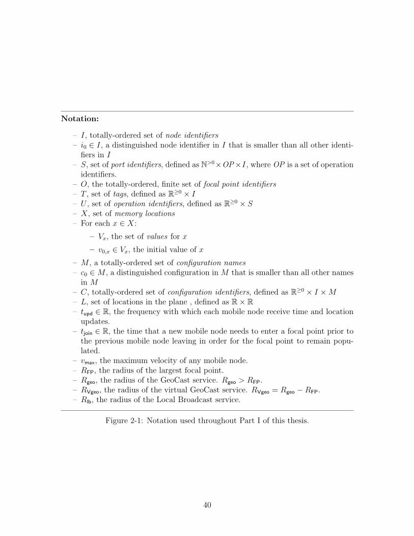
Notation:
– I, totally-ordered set of node identifiers– i0 ∈ I, a distinguished node identifier in I that is smaller than all other identi-
fiers in I– S, set of port identifiers, defined as N>0×OP×I, where OP is a set of operation
identifiers.– O, the totally-ordered, finite set of focal point identifiers– T , set of tags, defined as R≥0 × I– U , set of operation identifiers, defined as R≥0 × S– X, set of memory locations– For each x ∈ X:
– Vx, the set of values for x
– v0,x ∈ Vx, the initial value of x
– M , a totally-ordered set of configuration names– c0 ∈M , a distinguished configuration in M that is smaller than all other names
in M– C, totally-ordered set of configuration identifiers, defined as R≥0 × I ×M– L, set of locations in the plane , defined as R× R– tupd ∈ R, the frequency with which each mobile node receive time and location
updates.– tjoin ∈ R, the time that a new mobile node needs to enter a focal point prior to
the previous mobile node leaving in order for the focal point to remain popu-lated.
– vmax, the maximum velocity of any mobile node.– RFP, the radius of the largest focal point.– Rgeo, the radius of the GeoCast service. Rgeo > RFP.– RVgeo, the radius of the virtual GeoCast service. RVgeo = Rgeo −RFP.– Rlb, the radius of the Local Broadcast service.
Figure 2-1: Notation used throughout Part I of this thesis.
40
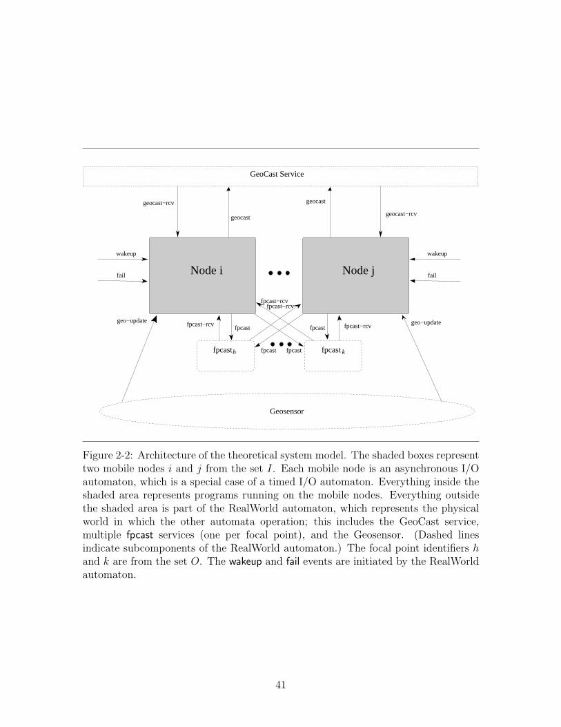
fpcastkfpcasth
GeoCast Service
geocast
fpcast fpcast
fpcast−rcvfpcast−rcv
geo−update geo−update
geocast−rcv
geocastgeocast−rcv
fpcast−rcvfpcast fpcast fpcast−rcv
Geosensor
Node jNode i
wakeup wakeup
failfail
Figure 2-2: Architecture of the theoretical system model. The shaded boxes representtwo mobile nodes i and j from the set I. Each mobile node is an asynchronous I/Oautomaton, which is a special case of a timed I/O automaton. Everything inside theshaded area represents programs running on the mobile nodes. Everything outsidethe shaded area is part of the RealWorld automaton, which represents the physicalworld in which the other automata operation; this includes the GeoCast service,multiple fpcast services (one per focal point), and the Geosensor. (Dashed linesindicate subcomponents of the RealWorld automaton.) The focal point identifiers hand k are from the set O. The wakeup and fail events are initiated by the RealWorldautomaton.
41

42

Chapter 3
Virtual Infrastructure
In this chapter, we introduce two types of virtual infrastructure: an infrastructurebased on virtual objects and an infrastructure based on virtual nodes.
The first of these abstractions is the Virtual Object Layer.1 The Virtual ObjectLayer is a shared object model: clients (i.e., the mobile nodes) can perform operationson virtual objects that reside at pre-determined, potentially changing, locations inthe network. From the perspective of a client, the virtual objects behave exactly asobjects in a typical shared object model.
The second of these abstractions, the Virtual Node Layer, generalizes the Vir-tual Object Layer. Each virtual entity is similar to a mobile node in that it is anautomaton that can broadcast and receive messages. Unlike a virtual object, a vir-tual node can initiate activity (i.e., messages and computation) directly, rather thansimply responding to client requests. Also, virtual nodes can communicate with eachother via a virtual GeoCast service. For example, virtual nodes can transport datafrom one end of a network to the other by transmitting it along a chain of virtualnodes. Clients and virtual nodes communicate with each other via a virtual GeoCastservice.
We begin in Section 3.1 by introducing the Virtual Object Layer. We continue inSection 3.2 to introduce the Virtual Node Layer. Finally, in Section 3.3, we brieflydiscuss a few examples of applications that can be built using the Virtual Node Layer.A more detailed and extensive example using the Virtual Object Layer is describedin Chapter 6.
3.1 Virtual Object Layer
The Virtual Object Layer is a simple shared-object model that hides the underlyingdynamics of a mobile ad hoc networks. The Virtual Object Layer consists of threetypes of entities: clients, virtual objects, and a RealWorld automaton modellingthe environment:
1This model was previously referred to as the Focal Point Object Model in [32,33].
43

jClient
Focal PointObject
Focal PointObject
Focal PointObjecth k l
iClient
invoke / responseinvoke / responseinvoke / response
RealWorld
geo−update geo−update
Figure 3-1: Virtual Object Layer. The clients interact with the virtual objects viainvocations and responses.
44
• Each client is modelled as an asynchronous I/O automaton. The clients interactwith the virtual objects.
• Each virtual object is specified by a variable type specification, and is also mod-elled as an asynchronous I/O automaton, specifically the canonical automatonthat implements the specified variable type. Recall (see Appendix A for moredetails) that a variable type specification consists of (1) a set of values V , (2)some initial value v0 ∈ V , (3) a set of invocations I, (4) a set of responses R, and(5) a deterministic transition function f : I × V → R× V , that is, mapping aninvocation and a state to a response and a new state. Given such a type speci-fication, the associated canonical automaton is a trivial atomic implementationof the shared object with the semantics specified by the type specification. (SeeAppendix A for more details.) Virtual objects receive invocations from theclients and return responses generated by the transition function based on theinvocation and their current state.
• The RealWorld automaton models the (virtual) environment and is a timed I/Oautomaton. The RealWorld maintains the location of each client, along withthe real time, and delivers geo-updates to the clients. Updates occur at leastevery time tupd. Since an asynchronous I/O automaton is a special case of atimed I/O automaton, and hence it is possible to composed the untimed clientswith the timed RealWorld.
The Virtual Object Layer is presented schematically in Figure 3-1, where a set ofclients interacts with a set of virtual objects.
Notice that the clients and virtual objects are modelled as asynchronous automata,although they receive updates from the RealWorld that contain timing information.In Section 3.1.2 we introduce further timing assumptions that are used when analyzingthe liveness and performance of the Virtual Object Layer.
Client / Virtual Object Interactions. The clients communicate only throughtheir interactions with the shared objects; there is no message-passing network. Eachclient has a (countably) infinite number of invocation/response ports onto each sharedobject, allowing it to invoke concurrent operations on an object. That is, the port setQ of each object is S = N>0×OP × I, where OP is a set of operations (for example,read, write, enqueue, dequeue, etc.). As is usual in shared object models, the clientscan invoke only one operation at a time on each port of an object.
Virtual Objects and Focal Points. Each virtual object is associated with a focalpoint in the set O. At any given time, a virtual object resides at the center of itsassociated focal point. Specifically, if a virtual object is associated with focal pointh, then at time t, the virtual object resides at the location fp-centerh(t).
If the function fp-centerh is constant over time, then the virtual object associatedwith h remains in the same location throughout an execution. If both functionsfp-centerh and fp-regionh are constant over time, we say that virtual object h is static.
45

If every virtual object h ∈ O is static, then we refer to this case as the Static VirtualObject Layer. Otherwise, we refer to the general case as the Dynamic VirtualObject Layer2.
3.1.1 Virtual Object Failures
The virtual objects are fault prone. That is, a virtual object can fail during an execu-tion, at which point it ceases to respond to invocations. The failure or correctness ofa virtual object depends only on the client population of its associated focal point. Ifa focal point region is populated throughout an execution, then its associated virtualobject is correct. If, on the other hand, a focal point region becomes depopulated,then the virtual object associated with that focal point may fail. Note that it doesnot matter how a focal point region becomes depopulated, be it as a result of clientsfailing, leaving the area, etc. Any depopulation results in the virtual object failing.We do not consider the possibility of a virtual object recovering; the same recoverydefinitions and techniques discussed in the context of a virtual node (see Section 3.2.3)can be applied to a virtual object.
A focal point is populated throughout a finite execution fragment if for somesufficiently large constant tjoin there exists a sequence, j0, . . . , jk of clients such that:
• Client j0 is well inside the focal point region when the execution fragment begins,and remains well inside the focal point region until at least time tjoin. That is,the location of node j0 at the beginning of the execution fragment throughtime tjoin is within the inner region specified for the focal point, i.e., its locationsatisfies Equation 2.1. We refer to the time at which j0 first leaves the innerregion as the departure time for j0.
• For every ` < k, client j`+1 is well inside the focal point region at least tjoinprior to the departure time for j`, and remains well inside the focal point regionand non-failed until at least time tjoin after the departure time for j`. We referto the first time after the departure time of j` at which j`+1 leaves the innerregion as the departure time of j`+1. The constant tjoin will be specified laterin Sections 4.3 and 5.3 when analyzing the performance of the Virtual ObjectLayer3.
2Notice that the location of a virtual object is, in many ways, irrelevant to the clients that areusing these objects: the objects behave in the same manner regardless of their location. However,the location of a virtual object—as determined by its associated focal point—affects its correctness,since it remains correct only if its associated focal point region is populated. Thus it may be desirablefor a virtual object to inhabit regions that are more populated. The location of a virtual object mayalso affect the cost of accessing it, if one were to account for the cost of a long-distance geocast; wedo not examine this latter metric, however.
3Notice that this definition requires a mobile node to be well inside a focal point region at leasttime tjoin prior to the earlier node leaving. As we have not yet made any liveness assumptions aboutthe underlying physical system, we cannot at this point quantify tjoin; intuitively, this time intervalmust be long enough for the focal point join protocol to complete and for any messages in the processof being delivered to arrive. In Sections 4.3 and 5.3, where we analyze the performance of one ofour protocols, we quantify more precisely the size of tjoin.
46

• Client jk is well inside the focal point region at the end of the execution frag-ment.
A focal point is populated throughout an infinite execution fragment if it is populatedfor all finite prefixes of the execution fragment. Thus a virtual object is correct insome execution if its associated focal point is populated throughout that execution.
3.1.2 Timing and Liveness
In this thesis, we consider primarily an asynchronous variant of this model, that is,there is no upper bound on how long an operation at a virtual object might take, andthere is no bound on the rate at which a client might take steps.
The Virtual Object Layer does, however, guarantee a lower bound on the durationof an operation at a virtual object: each operation takes some finite time > tupd. Thistechnical assumption proves useful in building applications using the Virtual ObjectLayer, as it implies that the updates provided by the RealWorld automaton aresufficiently frequent to distinguish when an operation begins from when an operationends.
For the sake of analyzing performance, however, we will consider a synchronousvariant of the Virtual Object Layer in which:
• Client responsiveness: Any enabled action at a client is executed immediately.
• Virtual object responsiveness: If a correct client i at some location ` invokes anoperation on a correct focal point h and remains forever within distance Rgeo
of location `, then eventually i receives a response from h. In particular, thereis an upper bound on how long i waits to receive a response.
This describes a special case of a timed I/O automaton (similar to the model presentedin [75]) in which certain tasks have upper bounds associated with them.
Simple Example
As a very simple toy example of an algorithm that uses the Virtual Object Layer,consider the problem of implementing an unreliable atomic read/write memory inthe Virtual Object Layer. In Chapter 6, we provide a more complete and involvedexample, involving the implementation of a reliable atomic read/write memory. Inthis simple example, we use only a single virtual object, h ∈ O, with operationsOP = {read, write}. The virtual object implements the read/write memory variabletype (presented, for reference, in Figure A-1). In order to perform read and writeoperations, the client simply invokes the appropriate operation on the virtual object.For example, when client i wants to satisfy a read request, it simply invokes the readoperation on the virtual object. It does this by performing the following transition:invoke(〈read〉)p where port p = 〈1, read, i〉, a port for client i on object h. Eventually,the virtual object responds as follows: respond(〈read-ack, val〉)p. At this point, theclient i can return the value. A write operation proceeds similarly, invoking the writeoperation on an appropriate port of the virtual object.
47
This simple algorithm solves the problem of implementing unreliable read/writeatomic memory in the Virtual Object Layer. This algorithm is, effectively, a cen-tralized solution that depends on a single virtual object. If the virtual object h fails(because, say, the focal point itself becomes depopulated), then the read/write mem-ory itself fails. In Chapter 6, we describe a fault-tolerant algorithm for read/writeatomic memory in the Virtual Object Layer.
3.2 Virtual Node Layer
The Virtual Node Layer is a natural generalization of the Virtual Object Layer. Itis quite similar to the Virtual Object Layer with the exception that (1) each virtualentity is a virtual node, rather than a virtual object, and (2) the entities—virtualand real—communicate using a (virtual) GeoCast service, rather than through aninvocation-and-response mechanism. In addition, virtual nodes may recover, shouldthey fail.
The Virtual Node Layer consists of three types of entities: clients, virtual nodes,and a RealWorld automaton modelling the environment:
• Each client is modelled as an asynchronous I/O automaton.
• Each virtual node is modelled a deterministic, asynchronous I/O automaton.
• The RealWorld automaton models the (virtual) environment and is a timedI/O automaton. The RealWorld maintains the location of each client, alongwith the real time, and delivers geo-updates to the clients. (Notice that it doesnot deliver such updates to the virtual nodes.4) Updates occur at least everytime tupd. The RealWorld automaton also supports a virtual GeoCast broadcastservice, which allows clients and virtual nodes to geocast messages to each other.This service is discussed further in Section 3.2.4.
Notice that the clients and virtual nodes are modelled as asynchronous automata,although they receive updates from the RealWorld that contain timing information.In Section 3.2.5 we introduce further liveness and timing assumptions that are usedwhen analyzing the liveness and performance of the Virtual Node Layer.
3.2.1 Virtual Nodes and Focal Points
Each virtual node is associated with a focal point in the set O. At any given time,a virtual node resides at the center of its associated focal point. Specifically, if a
4In practice, it is often useful for the virtual nodes to be aware of time and location information.Modelling the virtual nodes as timed automata introduces significant complications into both thevirtual layer definition and into emulation algorithms. See [82] for an example of how to accomplishthis. In order to achieve some of the benefits of a timed model, a simple application-level techniquecan be used: nearby clients can be programmed to send time and location information to thevirtual nodes. This technique is a simple way of providing the virtual nodes with near-up-to-dateinformation, and was first introduced in [69].
48
virtual node is associated with focal point h, then at time t, the virtual node residesat the location fp-centerh(t). If the function fp-centerh is constant over time, then thevirtual node associated with h remains in the same location throughout an execution.If both functions fp-centerh and fp-regionh are constant over time, we say that virtualnode h is static. If every virtual node h ∈ O is static, then we refer to this caseas the Static Virtual Node Layer. Otherwise, we refer to the general case as theDynamic Virtual Node Layer.
3.2.2 Motion-Controlled Clients
Throughout this section, we have assumed that the clients have no control over theirown motion. In some cases, however, we may be interested in considering a VirtualNode Layer in which the clients can direct their own motion. As in the case of themobile nodes (see Section 2.2.3), it is a simple modification to support clients thatexecute an algorithm to control the clients motion. Specifically, each client is assumedto produce (as an output) some motion control signal, for example, move(. . .). Thissignal may be in the form of a velocity vector, a target waypoint, or any other desiredform of motion control signal. In practice, the most common such signal is accelera-tion. The RealWorld automaton, as a model of the environment, receives such signalsas input and uses them to update the location of the clients.
3.2.3 Virtual Node Failures
The virtual nodes are fault prone, but may recover. The failure and recovery of avirtual node depends only on the client population of its associated focal point. If afocal point region is populated throughout an execution fragment, then its associatedvirtual node is correct—after some initial interval of time. If, on the other hand, afocal point region becomes depopulated, then the virtual node associated with thatfocal point may fail. Note that it does not matter how a focal point region becomesdepopulated, be it as a result of clients failing, leaving the area, etc. Any depopulationresults in the virtual node failing. When the focal point region is re-populated, thenafter some sufficient interval of time, the virtual node recovers.
A focal point is populated throughout a finite execution fragment if for somesufficiently large constant tjoin there exists a sequence, j0, . . . , jk of clients such that:
• Client j0 is well inside the focal point region when the execution fragment begins,and remains well inside the focal point region until at least time tjoin. That is,the location of node j0 at the beginning of the execution fragment through time3tjoin is within the inner region specified for the focal point, i.e., its locationsatisfies Equation 2.1. We refer to the time at which j0 first leaves the innerregion as the departure time for j0.
• For every ` < k, client j`+1 is well inside the focal point region at least tjoin
prior to the departure time for j`, and remains well inside the focal point regionand non-failed until at least time tjoin after the departure time for j`. We referto the first time after the departure time of j` at which j`+1 leaves the inner
49
region as the departure time of j`+1. The constant tjoin will be specified laterin Sections 4.3 and 5.3 when analyzing the performance of the Virtual NodeLayer5.
• Client jk is well inside the focal point region at the end of the execution frag-ment.
A focal point is populated throughout an infinite execution fragment if it is populatedfor all finite prefixes of the execution fragment.
We say that a virtual node is correct in some execution fragment if its associatedfocal point is populated throughout that fragment, and either (1) the fragment inquestion is the very beginning of the execution, or (2) there is sufficient time prior tothe fragment for the virtual node to recover during which the focal point is populated.Formally, for every fragment α′ of a timed execution α of the Virtual Node Layer,we say that a virtual node h ∈ O is correct during α′ if focal point h is populatedthroughout α′ and either:
• fragment α′ is a prefix of α; or
• there exists a fragment α′′ of temporal length at least 2tjoin that precedes α′ inα (i.e., α′′.α′ is a fragment of α) and h is populated throughout α′′.α′.
3.2.4 The RealWorld and Virtual GeoCast
The clients and virtual nodes communicate using a GeoCast service, which is formallypart of the virtual RealWorld automaton that models the virtual environment. Thevirtual RealWorld automaton is similar to that of the underlying system, except that(1) it accounts for the failure status of clients and virtual nodes, instead of mobilenodes, (2) it accounts for the location of clients, instead of mobile nodes, and (3) itcontains a virtual GeoCast service as a sub-component, but no fpcast services.
Each client and virtual node can use the virtual GeoCast service to send messageto all the clients and virtual nodes within some radius R of a chosen destinationlocation. To distinguish this broadcast service from the GeoCast service in the un-derlying physical network, we refer to it as the virtual GeoCast service; when anode sends a message, we say that it performs a virtual-geocast(m, d), sending mes-sage m to destination d; when a node receives a messages, we say that it performs avirtual-geocast-rcv(m, d).
For technical reasons, it is useful in this case to specify an automaton for theRealWorld that captures the safety properties of the environment; this will be usefulwhen showing that a protocol satisfies the safety properties of the Virtual Node Layer.
5Notice that this definition requires a mobile node to join a focal point at least time tjoin prior tothe earlier node leaving. As we have not yet made any liveness assumptions about the underlyingphysical system, we cannot at this point quantify tjoin; intuitively, this time interval must be longenough for the focal point join protocol to complete and for any messages in the process of beingdelivered to arrive. In Sections 4.3 and 5.3, where we analyze the performance of one of our protocols,we quantify more precisely the size of tjoin.
50

(See Section 5.2.5.) In the case of the Virtual Object Layer, this was unnecessary asthe virtual objects had no interaction with the RealWorld automaton. In this case,however, the clients and virtual nodes communicate via the virtual GeoCast service,which is part of the RealWorld. Hence when showing that an algorithm correctlyemulates the Virtual Node Layer, it is useful to be able to discuss more precisely thebehavior of the RealWorld. We describe the RealWorld automaton by specifying thesafety properties that is exactly satisfies, and arguing that they are easily capturedin an automaton.
The virtual RealWorld automaton maintains in its state the following components:
• the current real time (a non-negative real);
• the location of each client (a mapping from I to L);
• the time at which the last geo-update occurred for each client (a mapping fromI to non-negative reals); this allows the RealWorld to ensure that updates aredelivered with sufficient frequency;
• a set consisting of every message m broadcast by the virtual GeoCast service;
• a set A ⊆ I ∪O consisting of all non-failed clients and virtual nodes.
Along with the virtual GeoCast interface—virtual-geocast and virtual-geocast-rcv—ithas an output fail action which causes a client or virtual node to fail. The automatonis defined so that its trace set consists of exactly those traces γ satisfying the followingproperties:
1. In trace γ, for each non-failed client i, a geo-update event occurs at least everytupd time.
2. Trace γ satisfies the integrity property (as defined in Chapter 2 in the contextof the GeoCast service):
Integrity : For any virtual GeoCast message m, location d, and client or virtualnode i ∈ I ∪O, if a virtual-geocast-rcv(m, d)i event occurs in an execution,then a virtual-geocast(m, d)j event precedes it, for some client or virtualnode j ∈ I ∪O.
Notice that it easy to define transitions that enforce exactly these two properties: theonly condition on the virtual-geocast-rcv is that the message to be delivered exists inthe set of previously broadcast messages; the only restriction on trajectories is thateach client receives geo-updates with sufficient frequency.
The virtual GeoCast service also satisfies a liveness property: reliable delivery (asis defined also in Chapter 2 in the context of the GeoCast service):
Reliable Delivery : For every virtual-geocast(m, d)i event that occurs at time twhere i ∈ I∪O, there exists some t′ > t+tupd and ε ≥ 0 such that: let j ∈ I∪Obe a client or virtual node satisfying the following:
51

– j is within distance R of location d at time t′;
– j remains within distance R of location d until time t′ + ε; and
– j is correct for the interval [t′, t′ + ε];
then a geocast-rcv(m, d)j event occurs at some point in the interval [t′, t′ + ε],delivering the message to j.
This property is treated as a restriction on the executions of interest in the virtualmodel. In particular, we will show that the Virtual Node Layer, when implementedusing the algorithm in Chapter 5, guarantees reliable delivery (along with some spe-cific performance metrics) when the underlying physical model guarantees additionalliveness and timing properties.
Recall that the underlying GeoCast service is parameterized by some deliveryradius Rgeo, meaning that messages are delivered to every mobile node within distanceRgeo of the specified destination. We now specify the delivery radius for the virtualGeoCast service. Let RFP be the maximum radius of any focal point. Recall (fromSection 2.3.2) that the radius Rgeo of the GeoCast service in the underlying mobilenetwork is > RFP. Fix RVgeo = Rgeo −RFP.
This choice of RVgeo allows us to relate the behavior of the underlying GeoCastservice in the mobile network to the virtual GeoCast service in the Virtual NodeLayer. For example, assume that some mobile node i GeoCasts a message m to somelocation d. We know, by assumption, that every mobile node within distance Rgeo ofd receives message m. In the Virtual Node Layer, we also want every virtual nodewithin distance RVgeo of location d to receive message m. In fact, if some focal pointcenter ` is within distance RVgeo of location d, then every mobile node in the focalpoint region receives message m. That is, we claim the following:
Lemma 3.2.1. For every geocast(m, d)i event that occurs at time t where i ∈ I,there exists some t′ > t+ tupd and ε ≥ 0 such that: assume that h ∈ O is a focal pointand j ∈ I is a mobile node that satisfy the following:
• the focal point center of h is within distance RVgeo of d at time t′,
• the focal point center of h remains within distance RVgeo of d through time t′+ε,
• mobile node j is inside the focal point region of h at time t′,
• mobile node j remains inside the focal point region of h through time t′ + ε,
• mobile node j does not fail prior to time t′ + ε,
then a geocast-rcv(m, d)j event occurs at some point in the interval [t′, t′+ε], deliveringthe message to node j.
Proof. We need to show the following three conditions for j to satisfy the ReliableDelivery property of the underlying GeoCast service, which implies the desired result:
52
• Mobile node j is within distance Rgeo of location d at time t′: Since j is insidefocal point h at time t′, we know that j is within distance RFP of the focal pointcenter for h at time t′. Moreover, the focal point center of h is within distanceRVgeo of d at time t′. Thus, by the triangle inequality, j is within distanceRgeo ≤ RVgeo + RFP of d at time t.
• Mobile node j remains within distance Rgeo of location d until time t′+ ε: Thisconclusion follows by the same argument, since j remains inside the focal pointregion for h through time t′ + ε, and since the focal point center for h remainswithin distance RVgeo of d through time t′ + ε.
• Mobile node j does not fail prior to time t′ + ε, by assumption.
3.2.5 Timing and Liveness
In this thesis we consider primarily an asynchronous variant of the Virtual NodeLayer. That is, there is no upper bound on the rate at which clients and virtualnodes take steps, and there is no upper bound on the delay of the virtual GeoCastcommunication service.
For the sake of analyzing performance, however, we will consider a synchronousvariant of the Virtual Node Layer in which:
• Any enabled action at a client is executed immediately.
• An enabled action at a virtual node is executed within a bounded time. Thatis, if at time t some action a is enabled at virtual node v, then after somebounded amount of time, either action a is executed, or at some point duringthat interval of time, some other action occurs such that action a is no longerenabled.
• The delay of the virtual-geocast/virtual-geocast-rcv communication service isbounded.
• For every execution, there is a bound on the ε specified in the reliable deliveryproperty of the virtual GeoCast service.
This describes a special case of a timed I/O automaton (similar to the model presentedin [75]) in which certain tasks have upper bounds associated with them.
3.3 Example Applications
In this section we briefly discuss some scenarios in which virtual nodes facilitate thedesign of algorithms. The algorithms described (briefly) in this section depend onusing virtual nodes to collect, disseminate, and process information. We focus inparticular on applications that involve dynamic virtual nodes, that is, virtual nodes
53

that travel through the network. In Chapter 6, we provide a complete example of aprotocol that uses static virtual objects to reliably store data in a changing network.
These examples are, loosely, related to the problem of maintaining dynamic datastructures in a mobile ad hoc network. For example, the first example in Section 3.3.1is related to the problem of routing, which in most implementations attempts to main-tain portions of a shortest-path tree. Due to the constantly changing environment,these algorithms are notoriously difficult to implement correctly and even harder toanalyze: it is rare for such a dynamic algorithm to have provably good performancein the worst case. We suggest that instead of maintaining these data structures ex-plicitly, it is easier to take advantage of the spatial topology of the mobile nodes anduse virtual nodes to collect and process the data.
3.3.1 Routing
We first consider the problem of point-to-point message routing that delivers messagesto specifically identified mobile nodes. Notice that the GeoCast service does notdeliver messages to specified nodes; instead, it sends messages to a particular regionof the network. Most routing algorithms (e.g., [42,84,85,93]) either track the locationof every mobile node in the system, or flood the entire network with messages todiscover the location of each node. Both approaches can be quite expensive, andoptimizations are difficult.
We suggest instead a routing scheme based on the compulsory protocol of Chatzi-giannakis et al. [20]. In its simplest version, a single virtual node travels through thenetwork, collecting and delivering messages. In order to send a message, a mobilenode i waits until it nears the virtual node, and then uses the geocast service to senda message to the virtual node’s (predicted) location. A mobile node can determinethat it is near to a virtual node by calculating the mobile node’s location at a giventime and comparing it to its own location. Since the mobile node receives time andlocation updates at least every tupd time, this calculation is never too far off. Thefirst time that the client receives a time update placing it within broadcast range ofthe virtual node, it transmits its messages. Underlying this idea is the assumptionthat a client will be within broadcast range of the virtual node for some time� tupd;this depends on the broadcast radius, the velocity of the client, and the velocity ofthe virtual node in question.
The virtual node collects messages that it has received, and waits to deliver themto clients. A client that wants to receive messages waits until the virtual node isnearby, and then requests from it any messages it has to deliver to that specificclient.
Recall that virtual nodes fail in empty regions of the network. However, whereverthere are nodes that need to send and receive messages, there is presumably enoughnetwork density to ensure that the virtual node does not fail. Notice, though, that thisalgorithm only works well when the populated regions of the network are “connected:”if a node in one populated region tries to send a message to a node in anotherpopulated region, but all paths between these two regions are sparsely populated, thevirtual node cannot deliver the message.
54

If the virtual node is correct, i.e., never enters a depopulated region of the net-work, then we can conclude under certain conditions that messages are delivered.Specifically, under the timing assumptions described in Section 3.2.5, along with theassumption that, every so often, a client is within broadcast range of the virtual nodefor sufficiently long to detect its presence and exchange information with it, then wecan conclude that every message will eventually be delivered. The time to deliverthe message can be calculated based on (1) how long it takes for the sending clientto approach the virtual node, and (2) how long it takes for the virtual node to reachthe receiving node. If the virtual node sweeps through the network, then we candetermine a bound on this time based on the size of the geographic region and thevelocity of the virtual node.
Using more virtual nodes can shorten the average message latency, while increasingthe overall cost of the protocol. For example, a set of virtual nodes may traverse thenetwork in a covering fashion; whenever two virtual nodes pass each other, theysend each other their stores of messages. In this way, all the messages spread to allthe virtual nodes. A more space-efficient algorithm might use the scheme developedin [20], where the virtual nodes form a snake, winding through the network in apseudorandom path, thus regularly visiting every populated region of the networkand delivering messages to the resident nodes.
Compared to typical routing schemes (such as DSR and AODV), these algorithmsare easier to tune, in terms of space versus latency trade-offs: by increasing the numberof virtual nodes, and thus the space, messages are more rapidly delivered. UnlikeDSR and AODV, the cost (in terms of message latency and space usage) of thesealgorithms scales with the number of virtual nodes and the size of the region beingcovered, rather than the number of nodes. On the other hand, using a Virtual NodeLayer has larger associated overhead costs, as it requires emulating a virtual layer.It remains an interesting experimental question whether it is feasible to implementrouting on a Virtual Node Layer in such a way that it is competitive with existingrouting protocols. (See [97] for ongoing progress in this direction.)
3.3.2 Data Collection
A common use of ad hoc networks is to monitor environmental sensors. For example,one might wish to evaluate the average temperature, the average remaining batterycharge, or the number of nodes in various regions of the network. (The latter appli-cation might be used to track animals or cars, or to determine the density of mobilenodes for other uses.)
We propose a very simple algorithm for collecting data in mobile (rather thanstatic) networks. As in the case of routing, we assign the main work to the virtualnodes, which systematically explore the region in question, collecting and aggregatingdata. The primary difference from the routing algorithm is that the data may beaggregated, both regionally and temporally, as it is being collected. A client canspecify as part of a query what sort of data the sensors should produce, and how the“network” should aggregate that data. The virtual nodes return only the necessarydata to the clients. The rate of data collection can be calculated, as in the case of
55
routing, by considering the velocity of the virtual node and the size of the geographicregion, under a similar set of performance and liveness assumptions. As in the case ofrouting, using more virtual nodes improves the performance, at the cost of increasedcommunication.
56
Chapter 4
The Virtual Object Emulator
In this chapter we present a protocol that implements the Virtual Object Layer. Themain goal of this chapter, then, is to show how to reliably emulate virtual objectsusing unreliable mobile nodes. The protocol for emulating a virtual object is basedon the replicated-state-machine approach, in which all the mobile nodes in a focalpoint region cooperate to emulate the associated virtual object. Clients, by con-trast, are emulated directly by the mobile nodes. The replicas for each virtual objectcoordinate using the fpcast service associated with the virtual object’s focal point;this broadcast service provides for reliable, totally ordered broadcast. The standardreplicated-state-machine techniques are extended to tolerate nodes joining and leav-ing the emulation. The result is a virtual object that remains reliable as long asthe associated focal point region remains “populated” with clients; if the focal pointregion becomes depopulated, then the associated virtual object fails.1
In Section 4.1 we present an overview of the Virtual Object Emulator, the algo-rithm which implements the Virtual Object Layer. In Section 4.2 we argue that theemulation is correct. In Section 4.3 we discuss the performance of the Virtual ObjectEmulator.
An extended abstract of this work appeared in the 17th International Symposiumon Distributed Computing (DISC 2003) [32], and a full version appeared in Dis-tributed Computing [33]. The version included here includes some minor edits andimprovements from the version in [33]. The protocol has been modified to toleratedynamic virtual objects, and new names have been chosen for various entities andprotocols. Specifically, the objects implemented are now referred to as virtual objects(rather than “focal point objects”), and the main emulation protocol is now referredto as the Virtual Object Emulator (rather than the “focal point emulator”).
1Note that it does not matter how a focal point region becomes depopulated, be it as a result ofmobile nodes failing, leaving the area, going to sleep, etc. Any depopulation results in the virtualobject failing.
57

4.1 Virtual Object Emulator
In this section we present the Virtual Object Emulator (VOE), an algorithm thatimplements the Virtual Object Layer described in Chapter 3. We focus in this sectionon describing how the emulator implements a single virtual object associated with asingle focal point h. Fix h ∈ O for the remainder of this section. The entire layer isemulated simply by executing one instance of this protocol for each h ∈ O.
The basic idea of the Virtual Object Emulator is to use mobile nodes in thefocal point region as replicas. Throughout an execution, mobile nodes move in andout of the focal point region. The nodes that are inside the focal point region at anygiven time act as replicas, and collaborate to implement the virtual object. They takeadvantage of the fpcasth service to implement a replicated state machine that toleratesnodes continually joining and leaving. This replicated state machine consistentlymaintains the state of the atomic object, ensuring that the invocations are performedin a consistent order at all mobile nodes.
The Virtual Object Emulator consists of two automata that run on each mobilenode. The VOE is designed to emulate a virtual object; it is not involved in emulatingthe client. The emulator consists of two components: the VOE-Client and theVOE-Server, which communicate with each other using the GeoCast service. Noticethat both components of the emulator, though executing on the same mobile node,interact only via the GeoCast service. For each virtual object h′ ∈ O we assume adistinct instantiation of both Virtual Object Emulator components; recall that weare describing here the implementation of a single virtual object h.
Figure 4-1 depicts the various components, along with the two broadcast servicesGeoCast and fpcasth. The clients (not depicted) send invocations to the VOE-Clients(on the left), which attach a tag to every request and broadcast the request to a focalpoint using the GeoCast service. Within the focal point, the request is received by theVOE-Servers. The VOE-Servers then coordinate amongst themselves to determinean ordering of the requests. They accomplish this coordination using the fpcasthservice, which delivers messages to all of the VOE-Servers in the same order. Thistotal ordering determines the order in which the VOE-Servers process the requests.Based on this (ordered) sequence of requests, the VOE-Servers consistently updatetheir local replicas of the atomic object, and send a response back to the originatingVOE-Client using the GeoCast service. The VOE-Client then removes duplicates, anddelivers the response to the client.
The VOE-Client runs on every mobile node that wants to access atomic object h;the VOE-Server runs on every mobile node and is active when the mobile node is wellinside2 the focal point region corresponding to the atomic object. We now proceedto describe these two components in more detail.
58

!"#!$%&'("
!"#!$%&'("
!"#!$%&'("
!"#!$%&'("
!"#!$%&'("
!"#!$%&'("
)"*+"*
,-.
/"%012'-34"2(
!"#2'5(!*2+
!"#2'5(
6%2'5(
6%2'5(!*2+
)"*+"*
,-.
/"%012'-34"2(
!"#2'5(
!"#2'5(!*2+ 6%2'5(
6%2'5(!*2+
)"*+"*
,-.
/"%012'-34"2(
!"#2'5(
!"#2'5(!*2+ 6%2'5(
6%2'5(!*2+
701"8(
,-.*"5%#8&
18+#9" !"#2'5(
!"#2'5(!*2+
701"8(
,-.*"5%#8&
18+#9"
!"#2'5(!*2+
!"#2'5(
*"5%#8&
18+#9"
701"8(
,-.
!"#2'5(!*2+
!"#2'5(
:"(;#*9
6%2'5(
:"(;#*9
<"#7'5(
Figure 4-1: Diagram of the Virtual Object Emulator for emulating a single virtualobject h. Each of the VOE-Clients and VOE-servers may execute on a different mobilenode. When a VOE-Client (on the left) receives an invocation, it sends the requestto all the VOE-Servers using the GeoCast service. At least one of the VOE-Serversbroadcasts the request to all the other VOE-Servers in the focal point, using thefpcasth service. Each VOE-Server then updates its object replica as a result of therequest. At this point, at least one VOE Server sends a response to the originatingVOE-Client, using the GeoCast service. The VOE-Client then filters out extraneousresponses and delivers a response.
59

Figure 4-2: Automaton VOE-Client: Signature and Statefor client i and object obj of variable type τ = 〈V, v0, invocations, responses, δ〉
1 Input:2 invoke(inv)p, inv ∈ invocations, p ∈ Q3 geocast-rcv(〈response, resp, oid, loc〉, d)i, resp ∈ responses, oid ∈ U, d ∈ L
4 geo-update(l, t)i, l ∈ L, t ∈ R>0
5
6 Output:7 geocast(m, d)i, m ∈ invoke × invocations × U × L × L, d ∈ L8 respond(resp)p, resp ∈ responses, p ∈ Q9
10 Constants:11 fp-center : Rˆ{≥ 0} → L, a function mapping time to the focal point center12 fp-region : Rˆ{≥ 0} → P(L), a function mapping time to the focal point region13
14 State:
15 clock ∈ R≥0, the current time, initially 0, updated by the geosensor16 location ∈ L, node i′s location, initially i′s initial location, updated by the geosensor17 ready-responses ⊆ Q × responses, a set of an operation responses, initially ∅18 geocast-queue, a queue of messages to be geocast, initially ∅19 ongoing-oids ⊆ U, a set of operation identifiers, initially ∅
60

Figure 4-3: Automaton VOE-Client: Transitionsfor client i and object obj of variable type τ = 〈V, v0, invocations, responses, δ〉
1 Input invoke(inv)p
2 Effect:3 new-oid ← 〈clock, p〉4 Enqueue(geocast-queue, 〈〈invoke, inv, new-oid, location〉, fp-center(clock)〉)5 ongoing-oids ← ongoing-oids ∪ {new-oid}6
7 Input geocast-rcv(〈response, resp, oid, loc〉, d)i
8 Effect:9 if (oid ∈ ongoing-oids) then
10 〈c, p〉 ← oid11 ready-responses ← ready-responses ∪ {〈p, resp〉}12 ongoing-oids ← ongoing-oids − {oid}13
14 Input geo-update(l, t)i
15 Effect:16 location ← l17 clock ← t18
19 Output geocast(m, d)i
20 Precondition:21 Peek(geocast-queue) = 〈m, d〉22 Effect:23 Dequeue(geocast-queue)24
25 Output respond(resp)p
26 Precondition:27 〈p, resp〉 ∈ ready-responses28 Effect:29 ready-responses ← ready-responses − {〈p, resp〉}
61

4.1.1 VOE-Client
The signature and state of the VOE-Client are presented in Figure 4-2, and thetransitions for the VOE-Client are presented in Figure 4-3. The VOE-Client hasthree basic purposes. First, it ensures that each invocation receives at most oneresponse by eliminating duplicates. It accomplishes this by attaching a unique tagto each request and delivering only one response for each tag. Second, it instantiatesthe invoke/response interface for the virtual object, delivering the requests via theGeoCast service to the actual replicas responsible for emulating the virtual object.Third, it provides each mobile node with multiple ports with which to access thevirtual object.
4.1.2 VOE-Server
The VOE-Server performs the actual replicated emulation of the virtual object. TheVOE-Server implements a replicated state machine. Thus, each mobile node, whenit is active in the emulation, maintains a copy of the state of the virtual object. Themobile nodes use the total-ordering property of the fpcasth service to ensure that thereplicated state is updated consistently. Figure 4-4 contains the signature and stateof the VOE-Server. The remaining code for the VOE-Server is in Figures 4-5 and 4-5.
Emulator State. We begin by enumerating the elements of the VOE-Server’s state:
• The clock and the location variables store the time and location informationfrom the most recent geo-update.
• The status determines whether the emulator is currently participating in theemulation as a replica, joining the emulation, or idle.
• The value val stores the current state of the replica.
• The join-id is a unique identifier selected and used during the join protocol.
• The fpcast-queue and geocast-queue are two queues storing outgoing messagesfor the respective broadcast services.
• The answered-join-reqs is a set indicating which join requests have already beenanswered.
• The queue pending-ops stores messages waiting to be processed.
• The queue completed-ops stores messages that have already been processed.
• The counter fpcast-cnt is used to ensure that each fpcast message is unique.
2Recall that a mobile node is well inside a focal point region when it is sufficiently deep insidethe region, as was defined in Section 2.2.2.
62
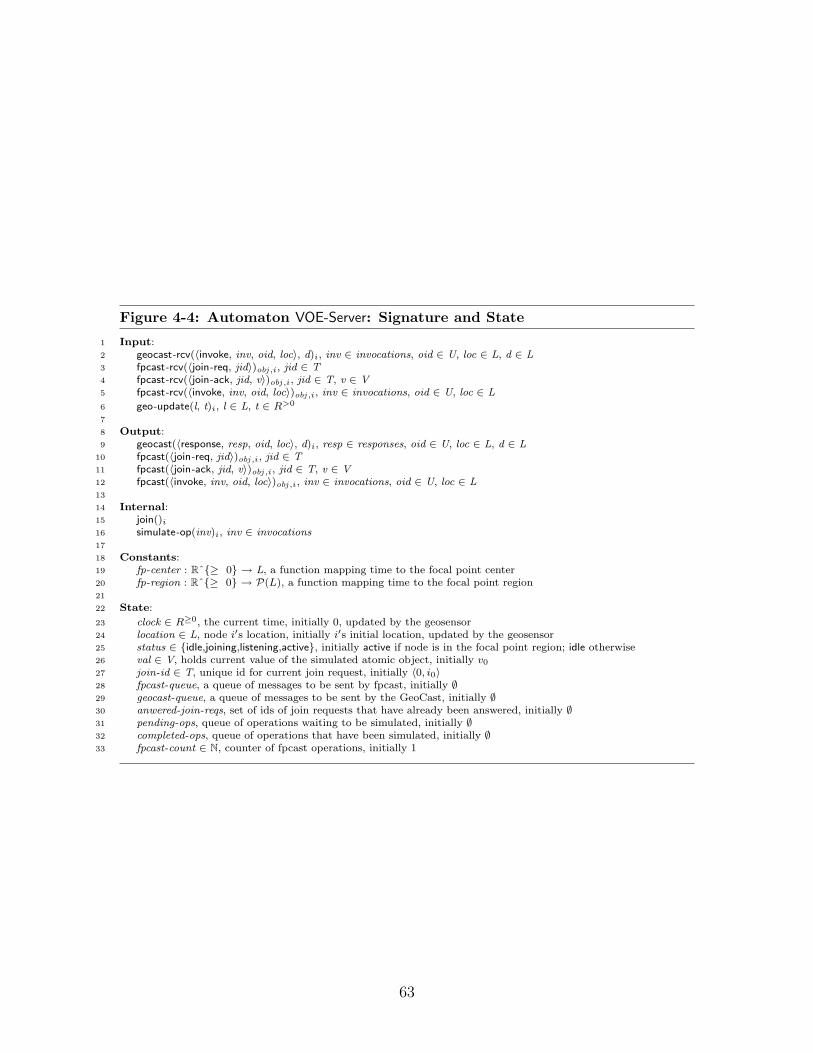
Figure 4-4: Automaton VOE-Server: Signature and State
1 Input:2 geocast-rcv(〈invoke, inv, oid, loc〉, d)i, inv ∈ invocations, oid ∈ U, loc ∈ L, d ∈ L3 fpcast-rcv(〈join-req, jid〉)obj ,i, jid ∈ T4 fpcast-rcv(〈join-ack, jid, v〉)obj ,i, jid ∈ T, v ∈ V5 fpcast-rcv(〈invoke, inv, oid, loc〉)obj ,i, inv ∈ invocations, oid ∈ U, loc ∈ L
6 geo-update(l, t)i, l ∈ L, t ∈ R>0
7
8 Output:9 geocast(〈response, resp, oid, loc〉, d)i, resp ∈ responses, oid ∈ U, loc ∈ L, d ∈ L
10 fpcast(〈join-req, jid〉)obj ,i, jid ∈ T11 fpcast(〈join-ack, jid, v〉)obj ,i, jid ∈ T, v ∈ V12 fpcast(〈invoke, inv, oid, loc〉)obj ,i, inv ∈ invocations, oid ∈ U, loc ∈ L13
14 Internal:15 join()i
16 simulate-op(inv)i, inv ∈ invocations17
18 Constants:19 fp-center : Rˆ{≥ 0} → L, a function mapping time to the focal point center20 fp-region : Rˆ{≥ 0} → P(L), a function mapping time to the focal point region21
22 State:
23 clock ∈ R≥0, the current time, initially 0, updated by the geosensor24 location ∈ L, node i′s location, initially i′s initial location, updated by the geosensor25 status ∈ {idle,joining,listening,active}, initially active if node is in the focal point region; idle otherwise26 val ∈ V, holds current value of the simulated atomic object, initially v0
27 join-id ∈ T, unique id for current join request, initially 〈0, i0〉28 fpcast-queue, a queue of messages to be sent by fpcast, initially ∅29 geocast-queue, a queue of messages to be sent by the GeoCast, initially ∅30 anwered-join-reqs, set of ids of join requests that have already been answered, initially ∅31 pending-ops, queue of operations waiting to be simulated, initially ∅32 completed-ops, queue of operations that have been simulated, initially ∅33 fpcast-count ∈ N, counter of fpcast operations, initially 1
63
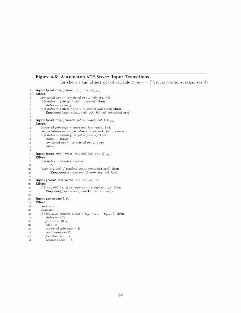
Figure 4-5: Automaton VOE-Server: Input Transitionsfor client i and object obj of variable type τ = 〈V, v0, invocations, responses, δ〉
1 Input fpcast-rcv(〈〈join-req, jid〉, cnt, k〉)obj ,i2 Effect:3 completed-ops ← completed-ops ∪ 〈join-req, jid〉4 if ((status = joining) ∧ (jid = join-id)) then5 status ← listening6 if ((status = active) ∧ (jid 6∈ answered-join-reqs)) then7 Enqueue(fpcast-queue, 〈join-ack, jid, val, completed-ops〉)8
9 Input fpcast-rcv(〈〈join-ack, jid, v, c-ops〉, cnt, k〉)obj ,i10 Effect:11 answered-join-reqs ← answered-join-reqs ∪ {jid}12 completed-ops ← completed-ops ∪ 〈join-ack, jid, v, c-ops〉13 if ((status = listening) ∧ (jid = join-id)) then14 status ← active15 completed-ops ← completed-ops ∪ c-ops16 val ← v17
18 Input fpcast-rcv(〈〈invoke, inv, oid, loc〉, cnt, k〉)obj ,i19 Effect:20 if ((status = listening ∨ active)21 ∧22 (〈inv, oid, loc〉 6∈ pending-ops ∪ completed-ops)) then23 Enqueue(pending-ops, 〈invoke, inv, oid, loc〉)24
25 Input geocast-rcv(〈invoke, inv, oid, loc〉, d)i
26 Effect:27 if (〈inv, oid, loc〉 6∈ pending-ops ∪ completed-ops) then28 Enqueue(fpcast-queue, 〈invoke, inv, oid, loc〉)29
30 Input geo-update(l, t)i
31 Effect:32 clock ← t33 location ← l34 if (depthobj (location, clock) < tupd ·(vmax + vfp-max)) then35 status ← idle36 join-id ← 〈0, i0〉37 val ← v0
38 answered-join-reqs ← ∅39 pending-ops ← ∅40 fpcast-queue ← ∅41 geocast-queue ← ∅
64

Figure 4-6: Automaton VOE-Server: Internal and Output Transitionsfor client i and object obj of variable type τ = 〈V, v0, invocations, responses, δ〉
43 Internal simulate-op(inv)i
44 Precondition:45 status = active46 Peek(pending-ops) = 〈invoke, inv, oid, loc〉47 Effect:48 if (〈invoke, inv, oid, loc〉 /∈ completed-ops) then49 (val, resp) ← δ(inv,val)50 Enqueue(geocast-queue, 〈〈response, resp, oid, loc〉, loc〉)51 Enqueue(completed-ops, Dequeue(pending-ops))52
53 Internal join()i
54 Precondition:55 depthobj (location, clock) ≥ tupd ·(vmax + vfp-max)56 status = idle57 Effect:58 join-id ← 〈clock, i〉59 status ← joining60 Enqueue(fpcast-queue, 〈join-req, join-id〉)61
62 Output fpcast(〈m, fpcast-count, i〉)obj ,i63 Precondition:64 Peek(fpcast-queue) = m65 Effect:66 fpcast-count ← fpcast-count +167 Dequeue(fpcast-queue)68
69 Output geocast(m, d)i
70 Precondition:71 Peek(geocast-queue) = 〈m, d〉72 Effect:73 Dequeue(geocast-queue)
65
Joining and Leaving the Emulation. The emulator transitions between threestatuses: idle, joining, listening, and active. We first discuss how a mobile node joinsthe emulation. The join protocol is activated when the mobile node enters the innerregion of focal point h, i.e., when it hears that it is well inside the focal point region. Inthis circumstance, the join transition is enabled (Figure 4-6, lines 53–60). This resultsin the mobile node broadcasting a join-request message using the fpcasth service, atwhich point it sets its status to joining and awaits a response.
The other active nodes in the focal point receive the join request (Figure 4-5,lines 1–7) and respond by sending the current replicated state of the virtual objectusing the fpcasth service. As an optimization to avoid unnecessary message traffic,if a node observes (by examining answered-join-reqs) that someone else has alreadyresponded to a join request, then it does not respond; only one node needs to senda join response. Notice (Figure 4-5, line 6) that only active nodes will send joinresponses. When the node that originated the join request receives its own joinrequest (Figure 4-5, lines 4–5), it sets its status to listening.
When the joining node receives a response to its join request (Figure 4-5, lines 9–16), it starts participating in the emulation, setting its status to active. This completesthe join protocol.
By contrast, ceasing to participate in the emulation does not require any coor-dination with other replicas. When a node hears that it has left the inner focalpoint region (either due its own motion, or the movement of the virtual object), itre-initializes its variables, and becomes idle (Figure 4-5, lines 30–41).
Responding to Invocations. We next discuss how active replicas respond to aninvocation. When a node participating in focal point h receives a GeoCast messagecontaining an invocation on object h (Figure 4-5, lines 25–28), it rebroadcasts theinvocation with the fpcasth service, thus ordering the invocation with respect to theother messages broadcast with the fpcasth service (i.e., join-request messages, joinresponses, and other operation invocations). Since it is possible that a GeoCastinvocation is received—and rebroadcast—by more than one node in the focal point,there is some bookkeeping to ensure that only one copy of the same invocation isactually processed by the nodes. We include an optimization that if a node observesvia the pending-ops or completed-ops queues that an invocation has already been sentby the fpcasth service, then it does not do so again.
Active nodes keep track of invocations in the order in which they receive theinvocation messages via the fpcasth service (Figure 4-5, lines 18–23). Duplicatesare discarded using the unique operation identifiers, which are stored in the setspending-ops and completed-ops . The operations are then performed (Figure 4-6,lines 43–51) on the simulated state in this order. After each operation is executed, aGeoCast is sent back to the invoking node with the operation’s response. We can besure that the invoking node receives a response when it remains in the same regionfrom which it sent the invocation, allowing the GeoCast to find it.
There are some subtle points involved in deciding when during the process of join-ing the emulation a node should start recording invocation messages, when a node
66

should start executing operations, and when a node should start sending responses.During the process of joining, a node receives a snapshot of the object’s state. How-ever by the time the snapshot is received, it might be out of date, since there mayhave been some intervening messages delivered by the fpcasth service that have beenreceived since the snapshot was sent. Therefore the joining node must record allthe operation invocations that are broadcast after its join request was broadcast butbefore it receives the snapshot. This is accomplished by having the joining node en-ter a “listening” state once it receives its own join-request message; all invocationsreceived when a node is in either the listening or the active state are recorded, andactual processing of the invocations can start once the node has received the snap-shot and has the active status. The processing consists of first emptying the queueof waiting invocations, and then proceeding to handle newly arrived invocations.
A final point to notice is that every message sent by the fpcasth service is unique:attached to each message is a counter (fpcast-cnt) and the process identifier; eachprocessor increments its counter after each fpcast, ensuring that no message is dupli-cated. Notice that each message m that is fpcast is of the form 〈P, cnt , k〉, where cntis a counter and k is a node identifier. We refer to P as the payload of m.
4.2 Analysis
In this section we show that the Virtual Object Emulator correctly implements theVirtual Object Layer. We first focus on a single focal point h, and show that theVirtual Object Emulator for h correctly emulates the canonical atomic object associ-ated with h. The key tool in this proof is Theorem A.3.2 (see Appendix A.3 for moredetails). In order to use this theorem, we define a total order on all the operationssimulated by the VOE, and show that this order satisfies certain properties. Once wehave shown that each individual VOE emulates a single virtual object, we argue thatthe entire emulation of all the virtual objects results in an emulation of the VirtualObject Layer. Of note, throughout this proof, we depend only on the basic timingassumptions described in Chapter 2, i.e., the accurate time and location updates re-ceived sufficiently frequently from the (RealWorld) GeoSensor. In Section 4.3, wemake additional timing assumptions regarding the behavior of the mobile nodes andthe broadcast service, and analyze the performance of the emulator.
We begin by describing what it means for the Virtual Object Emulator to emulatethe Virtual Object Layer. For each h ∈ O, let Ah be the canonical atomic objectautomaton specified by the type of virtual object h. (See Appendix A.3 for a defini-tion of the canonical atomic object automaton.) Notice that Ah is an asynchronousautomaton, formalized with TIOA, that is, with arbitrary time passage between dis-crete events. Let S be the composition of all the VOE-Clients, VOE-Servers, and theRealWorld, where all the actions that are not invoke, respond, or geo-update actionsare hidden. For each h ∈ O, let Sh be automaton S with all actions except for invo-cations and responses for object h hidden. Thus, the external interface to Sh consistsonly of invoke and respond actions on object h. (Notice that all the hidden actionsare output actions, since the only inputs to S are invoke actions.) The result of this
67
definition is that the external interface of Sh is identical to the external interfaceof Ah.
Our first goal is to show that every trace of Sh is also a trace of Ah. That is, forevery possible pattern of invocations by the clients, the result trace of the emulator isalso a trace of the atomic object Ah. The majority of the analysis lies in proving thisclaim. Notice that Sh is a timed automaton, while Ah is asynchronous in the sensethat it allows for arbitrary time passage events between discrete events. Note thattraces of Sh and Ah are both timed, even though Ah is asynchronous.
Once we have shown that every trace of Sh is also a trace of Ah, it remains toshow that for the entire composition of the emulators and the RealWorld, i.e., for theemulation of all the objects simultaneously, every trace is also a trace of the VirtualObject Layer. We show this fact in Section 4.2.4 by pasting together the individualclient and virtual object executions.
We now fix one h ∈ O and focus on showing that Sh implements Ah. In particular,we need to show that every trace of Sh is also a trace of Ah. (Again, recall thattraces are timed.) Formally, let U be any well-formed environment: a well-formedenvironment is an arbitrary timed automaton that preserves well-formedness. Ourgoal is to show that traces(U × Sh) ⊆ traces(U × Ah).
The main body of the proof consists of determining a total ordering on all theoperations of the object h, given an arbitrary execution in which all the operationscomplete. The total ordering is shown to have certain properties, allowing us toconclude that the algorithm correctly implements an atomic object. Specifically,the key properties are that the ordering is consistent with the real-time ordering ofoperations, and that the ordering is consistent with the responses sent during theexecution. We then use Theorem A.3.2 (see Appendix A.3 for further details) toconclude the proof.
Fix an arbitrary execution α of the system U × Sh in which every operationcompletes, where U is an arbitrary environment for Sh that is compatible with Sh
and preserves well-formedness. (Theorem A.3.2 indicates that we need only considerexecutions in which all the operations complete.) Let Π be the set of operationsin α. Since every operation completes, we know that for every operation π ∈ Π, forsome port p ∈ Q (the set of ports), an invoke(π)h,p event occurs in α, followed by arespond(π)h,p event.
We begin in Section 4.2.1 to define some notation, and a total order on the oper-ations in Π. These operations are ordered based on the order in which the associatedfpcast messages are delivered. We then proceed in Section 4.2.2 to prove certain prop-erties of this total order. Specifically, in Invariant 4.2.1 we prove the key property ofthe total order: at every point in the execution α, the replicated state of each VOEactive in the replication is equal to the state after some prefix of the ordered opera-tions. Notice that this claim alone is sufficient to show that the replicas agree on anan execution of the virtual object, and moreover that the agreed-upon execution isexactly defined by the total order on operations. In Section 4.2.3, we invoke Theo-rem A.3.2 to show that the VOE emulator Sh implements the virtual object Ah, andin Section 4.2.4 conclude that the VOE emulator as a whole implements the VirtualObject Layer.
68
4.2.1 Totally Ordered Operations
We begin by defining some preliminary notation. Recall that we have already fixed anexecution α of Sh × U . We define id(π) to be the unique identifier of each operationπ, and id(m) to be the operation identifier of each message m; for each prefix β of αwe define IM (β) to be the set of messages sent by the fpcasth service in β. Finally,we define a total order ≺ on the operations in Π based on the messages in IM (α).We proceed in more detail.
First, recall that every operation begins, by definition, with an invocation on someport, and notice that each operation π ∈ Π is assigned a unique identifier 〈clock , p〉by the VOE-Client before it is GeoCast to the VOE-Servers (see Figure 4-3, line 3).We refer to this identifier as id(π).
Second, for any prefix β of execution α, let IM (β) be the set of messages sent(and later delivered) by the fpcasth service in β. That is:
IM (β) = {m | ∃i ∈ I, fpcast(m)h,i ∈ β }
The set IM (β) contains one message m for every fpcast(m) event in β.
Third, since each message fpcast is unique, the properties of the fpcasth serviceguarantee that there exists a total ordering of the messages in IM (α) that is consistentwith the order in which each mobile node receives the messages. That is, if node ireceives two messages mr and mt in that order, then mr ≺ mt in the total ordering.Fix ≺ to be this ordering.
Fourth, notice that a “message” m consists of the tuple: 〈〈op, inv , oid , loc〉, ·, ·〉,the tuple sent by an fpcast. Each invoke message, that is, each message in whichop = invoke, includes an identifier oid 6= ⊥. If m is an invoke message, then letid(m) be the identifier associated with message m. This identifier is closely relatedto the identifier associated with operation, id(π) that led to this message: for eachinvoke message, oid is set to the unique identifier of an operation associated with thatmessage. (See Figure 4-5, line 28, and notice that the enqueued fpcasth message usesthe identifier from the received GeoCast request). This allows us to say that certainfpcasth messages are associated with each operation. However, it also means that theoid identifiers in each message are not unique: two fpcasth messages (sent by differentmobile nodes) may have the same oid identifier as they may result from two differentmobile nodes receiving the same geocast invoke message.
Finally, we define a total ordering on operations π ∈ Π as follows, using theordering ≺ induced by the fpcasth service. Let πi and πj be two operations in Π.For operation πi, let m1 be the first message according to the ordering ≺ in IM (α)associated with operation πi, that is, where id(m1) = id(πi). The message m1 is thefirst message delivered by fpcasth in α that was generated by operation πi.
Similarly, for operation πj, let m2 be the first message according to the ordering≺ in IM (α) such that id(m2) = id(πj). We say that πi ≺ πj if m1 ≺ m2. Sinceoperation identifiers are unique and an operation can only be associated in this waywith a single message (i.e., the first), this defines a total ordering on operations.
69

4.2.2 Properties of the Total Order
Our goal now is to show that the total ordering on operations satisfies the criteriaof Theorem A.3.2, thus implying that the emulation of atomic object Ah is correct.The most difficult property required by Theorem A.3.2 is Property 2: we need toshow that the total ordering of operations is consistent with the responses sent bythe VOE-Servers. In order to show this property, we focus on a key invariant thatrelates the total ordering to the state of each replica. Invariant 4.2.1 shows that atevery point in the execution, the state of each replica precisely reflects a prefix of theordered operations. From this we are able to conclude that each response sent by areplica is also consistent with the total order.
We begin by defining, for each prefix of α and for each replica i, a prefix of theordered messages in IM (α); this prefix of the ordered messages represents the set ofmessages processed by i. It is easy to see that every message processed by i is inthis set. We argue (in the proof to Invariant 4.2.1) that this set exactly captures theset of messages that have been processed to produce i’s replicated state. That is, i’sreplicated state is exactly the value v resulting from executing each operation in thisdesignated prefix of IM (α). We now proceed in more detail.
Let α′ be any finite prefix of execution α, and let i be any node. Recall thateach message m ∈ IM (α) consists of a payload P , along with a counter and a nodeidentifier. Of all the fpcasth messages ordered in IM (α′), we are interested in aparticular subset of these messages: those that are delivered in α′ to i that havenot had their payload added to pending-ops i. This subset includes all the messagesprocessed by i in α′, since every message processed by i has been received and is nolonger in the pending queue. More formally, define IM (α′, i) to be the set of messagesm̄ that satisfy the following three conditions:
1. fpcast-rcv(m̄)obj ,i occurs in α′, and
2. m̄ = 〈P, ·, ·〉 and
3. P /∈ `state(α′).pending-ops i.
Here `state(α′) denotes the last state in α′.
We now define γ(α′, i) to be the state of the atomic object after processing allthe operations in α′ up to and including the last operation in α′ processed by i, thatis, the operations represented by all the messages in IM (α′) up to and including thelargest message in IM (α′, i). (An operation is processed when it is applied to thestate of the atomic object.) We now define γ(α′, i) more formally.
First, choose m̄ to be the largest message (according to the total ordering ≺) inIM (α′, i). The message m̄ is, in effect, the most recent message that has been pro-cessed by node i: all prior messages have been received, added to the set pending-ops i,and then removed from the set pending-ops i; all later messages are in the set of pend-ing operations pending-ops i, or have not yet been received. If no such m̄ exists, i.e.,if IM (α′, i) = ∅, then set m̄ = ⊥.
70

We now define γ(α′, i) to be the state of the atomic object after processing allfpcasth messages in IM (α) prior to (and including) m̄. That is, γ(α′, i) is the state af-ter beginning in the initial state v0 and processing all the invoke messages for node i inIM (α), stopping after message m̄, while skipping the “duplicate” messages, referringto the same operation, that might occur in IM (α′). If m̄ = ⊥, then γ(α′, i) = v0.
Thus γ(α′, i) is the state after processing the operations, π1, π2, . . . , πt, where πt
is the most recent operation that i has processed in α′.We show that for every prefix α′ of execution α, if node i has completed the join
protocol, then the state of the replica at node i is equal to γ(α′, i). That is, thestate of the replica at node i is consistent with all prior operations in IM (α′) havingoccurred.
If node i has itself received all the messages in IM (α′), this claim is immediate,as it executes each operation that it receives. In the case that node i has joined thefocal point during the execution, however, node i may have received only a suffix ofthe sequence. As a result, the main difficulty in proving the following invariant isshowing that the join protocol works, i.e. that after a node sets its status to active,it has correctly acquired a good snapshot of the state of the world.
Invariant 4.2.1. Let α′ be any finite prefix of execution α. If `state(α′).status i =active, then `state(α′).vali = γ(α′, i).
Proof. We show this by induction on the length of α′. Throughout the induction, wealso maintain a second invariant. This sub-invariant shows that the sets pending-opsand completed-ops together reflect all the operations that i is aware of. Specifically,every message m′ that precedes the largest received message is in one of those twosets.
Invariant 4.2.2. For every i ∈ I: if `state(α′).status i = active and message m is thelargest message such that a fpcast-rcv(m)h,i occurs in α′, then for every message m′ ≤m, m′ ∈ IM (α′) where m′ = 〈P, ·, ·〉, the payload P is in `state(α′).pending-ops i ∪`state(α′).completed-ops i.
For the base case (for both the main invariant, as well as Invariant 4.2.2), considerthe initial state of the system, before any events occur in α. Let β′ be this emptyprefix of α. If i is not in the focal point region, then status i = idle, and bothclaims are trivial. If i is in the focal point, then the state of vali is v0. In this caseIM (β′) is empty, and as a result γ(β′, i) also equals v0, satisfying the main invariant.Invariant 4.2.2 follows from the fact that there are no messages received in the emptyexecution.
There are two types of inductive steps to consider for executions of timed au-tomata: discrete events and trajectories. Notice that for trajectories, the invariantsare trivially maintained since all the state elements mentioned in the invariants arediscrete and unchanged under time passage. Consider, then, a discrete event.
Let s and s′ be the states before and after the new event, respectively. Let β bethe previous prefix of α, that is, s = `state(β). Let β′ be the new prefix of α, that is,s′ = `state(β′).
71

We already know, inductively, that for any finite prefix α′ of execution β, forany node j ∈ I, if `state(α′).statusj = active, then: `state(α′).valj = γ(α′, j)), andInvariant 4.2.2 holds. We need to show that `state(β′).val i = γ(β′, i), and thatInvariant 4.2.2 continues to hold. We now consider the various actions relevant tothis claim.
• fpcast-rcv(〈〈invoke, inv , oid, loc〉, cnt , k〉)obj ,i: (Figure 4-5, lines 18–23.)
Recall that the set IM (β′, i) includes only messages that have been sent in β′,received by i, and whose payload is no longer in pending-ops i. As a result ofthis event, the message payload 〈invoke, inv , oid , loc〉 is added to pending-ops i,and therefore the sequence IM (β′, i) is equal to IM (β, i), and as a result,γ(β′, i) = γ(β, i). By induction, we already know that γ(β, i) = `state(β).val i.The state of the replicated object is also unchanged, that is: `state(β′).val i =`state(β).val i. The claim then follows.
We next proceed to argue that Invariant 4.2.2 is maintained. Notice that themessage m = 〈〈invoke, inv , oid , loc〉, cnt , k〉 is the largest message received by ifrom the fpcasth service in β′, since the total-ordering reflects the order in whichmessages are received. Let m′ be the largest message received by i in β from thefpcasth service. The induction hypothesis states that every message m′′ ≤ m′
in IM (β) has its payload in either pending-ops or completed-ops . Since thisevent does not remove messages from either of these sets, and since this eventadds payload 〈〈invoke, inv , oid , loc〉, ·, ·〉 to pending-ops , it remains to show thatfor every message m′ < m′′ < m in IM (β′), they payload of m′′ is either inpending-ops or completed-ops . Assume for the sake of contradiction that sucha message m′′ exists that its payload is not in either set. First, we argue thatthis implies that node i has exited the focal point region at some point afterreceiving message m′ and prior to receiving message m: since the payload ofevery message received from the fpcasth service is added to either pending-opsor completed-ops , and messages are removed only when i exits the focal pointregion, there are two possible cases:
– Node i exits the focal point region at some point between receiving m andm′, and resets pending-ops during the geo-update), removing message m′′
from pending-ops .
– Node i does not receive m′′. In this case, we conclude by the consistentdelivery property of the fpcasth service that i exits the focal point regionat some point between receiving m and m′.
Moreover, we know that message m′ is the most recent message received by iprior to m (since it is the largest message in β). Thus between receiving messagem and m′, node i exits the focal point region, setting its status to idle, and nodei does not receive a join-ack message, allowing it to reset its status to active,contradicting our assumption that i has a status of active.
• simulate-op(inv)i: (Figure 4-6, lines 43–51.)First, when this action occurs, status i = active, since that is a precondition
72

to this action (Figure 4-6, line 45). The invoke operation removes a messagepayload P = 〈inv , . . .〉 from the set pending-ops i, and in doing so adds messagem = 〈P, ·, ·〉 to IM (β, i). As a result, IM (β′, i) = IM (β, i) ∪ {m}.We next notice that the state γ(β, i) includes all the messages preceding m inIM (β′). Otherwise, it would imply that the message immediately precedingm in IM (β′) was not received by i in β and hence that i had left the focalpoint region and set status i = idle (during a geo-update), contradicting ourassumption that i is active.
The total-ordering guarantee of the fpcast service ensures that m is the largestmessage in IM (β′, i). There are two subcases to consider.
– Message m has the same payload as a message already received and pro-cessed. That is, there exists a message delivered earlier in the ordering withthe same invocation and operation identifier. In this case, γ(β′, i) = γ(β, i).It remains to show that val i is also unmodified as a result of the fpcast-rcvh
event. Inductively, we know from Invariant 4.2.2 that every message inIM (β) has its payload in pending-ops i ∪ completed-ops i. Thus, the ear-lier message with the same operation identifier also has its payload inpending-ops i ∪ completed-ops i. We know that it is not in pending-opsi , asthe payload for message m is the oldest in pending-ops (as it is a queue);from this we conclude that the earlier message is in completed-ops i, inwhich case the simulated-op event does not modify val i, and the main in-variant is maintained.
– Message m refers to a new operation, in which case γ(β′, i) = δ(inv , γ(β, i)).In this case, the state val i = γ(β, i) in state s, by induction. After thesimulate-op action, val i is set to δ(inv , γ(β, i)), as this is the definitionof how the object responds to invocations. This maintains the desiredinvariant.
Since this event neither results in a new message being received from the fpcasthservice, nor removes any message payloads from pending-ops ∪ completed-ops(only moving a message from one to the other), Invariant 4.2.2 is maintained.
• fpcast-rcv(〈〈join-ack, jid , v, c-ops〉, ·, ·〉)i: (Figure 4-5, lines 9–16.)In this event, node i sets status to active (Figure 4-5, line 14), if the messageis a response to an outstanding join-req previously sent by i. (If this is not thecase, then this action causes no change to status i, pending-ops i, or val i, and theinvariant is trivially maintained.)
The fpcasth service guarantees that if a message is received, an earlier fpcastoccurred at some node j that sent the message (that is, it guarantees messageintegrity). In particular, some node j previously fpcast a join acknowledgment,i.e., performed a fpcast(〈join-ack, jid , v, c-ops〉)j.
The only action that causes a join-ack to be sent is a prior join request beingreceived . Therefore, node j previously performed an fpcast-rcv(〈join-req, jid〉)i.Let β′′ be the prefix of β ending with the fpcast-rcv(〈join-req, jid〉)j action.
73

Consider the state of node j at the end of β′′. First, the status, statusj, mustbe active; otherwise node j would not send a response to the join request.Inductively, then, we know that `state(β′′).valj is equal to γ(β′′, j). Moreover,we can conclude that v, the value send from j to i, is also equal to γ(β′′, j).
Since val i is set to v when the join-ack message is received, i.e., during thetransition in question, it remains only to show that:
γ(β′, i) = γ(β′′, j) , (4.1)
and we can conclude that val i = γ(β′, i), as desired.
Let m be the largest message in IM (β′) received by i that does not have its pay-load in s′.pending-ops i, that is, m is the largest messages in IM (β′, i). We claimthat m must correspond to node i’s join request, which implies Equation 4.1.
First, notice that i ignores all messages that it receives before its own joinrequest. None of these messages have their payload added to pending-ops i, andtherefore m is no smaller than all such messages.
Second, notice that i adds the payload of every message it receives after its ownjoin request to pending-ops i because when i receives its own join request, it setsstatus i to listening (Figure 4-5, line 5). No message is removed from the setpending-ops i because status i is not yet active (Figure 4-6, line 45). Therefore mcannot be equal to any message received by i after i’s own join request.
We conclude, then, that m is exactly i’s join request. The state γ(β′, i) isdefined as the state reached after processing all messages prior to and includingm, that is, prior to i’s join request.
Notice, though, that i’s join request is exactly the last message processed by jin β′′ before sending a response to i. In particular, then, γ(β′′, j) is the statereached on processing every message in IM (β′′ prior to i’s join request.
Therefore, Equation 4.1 holds, and the invariant holds in state s′.
We next argue that Invariant 4.2.2 is also maintained. Notice that when nodej sends the join-ack message, it also includes a copy of its set completed-opsj ,and that at this point in the execution, Invariant 4.2.2 holds with respect toj, meaning that every message preceding node i’s join request has its payloadin pending-opsj ∪ completed-opsj. Since pending-opsj is a queue, and when re-sponding to the join request, all the messages preceding it have been removedfrom pending-opsj, we can conclude that every message preceding the join re-quest has its payload in completed-opsj. When node i receives the join-ack, itadds all the messages in the set c-ops to its own set completed-ops i. It remainsonly to show that every message sent after i’s join request has its payload inpending-ops i. This follows immediately from the fact that i has remained in thefocal point region, and the consistent delivery property of the fpcasth service.
The rest of the cases are straightforward, having no effect on the status of i, theelements of pending-ops i, or the state of the replicated object.
74
4.2.3 Atomicity
We can now show that the two properties required by Theorem A.3.2 hold for the totalordering we have defined, and as a result, that the Virtual Object Emulator correctemulates virtual object h. Specifically, the emulator Sh when composed with anywell-formed environment U is a correct implementation of the object Ah composedwith the same well-formed environment U .
Theorem 4.2.3. traces(Sh × U) ⊆ traces(Ah × U).
Proof. Fix some execution α of Sh × U . We consider the properties from Theo-rem A.3.2 in order:
1. (Property 1) Assume πi and πj are two operations and πi completes before πj
begins. We want to show that πi < πj in the total ordering. Let message m1
be the first message associated with operation πi, and let message m2 be thefirst message associated with operation πj. Since πi completes before πj begins,the message m1 must be received before the message m2 is sent, and thereforem1 precedes m2 in the total ordering induced by the fpcast service. This thenimplies that πi precedes πj in the total ordering on operations, as claimed.
2. (Property 2) We need to show that the total ordering on operations is consistentwith the responses output. This follows from Invariant 4.2.1.
Fix some operation π ∈ Π. Let inv 1, inv 2, · · · , invk be the invocations of theoperations preceding π in the total ordering, indexed according to the totalordering. Let inv(π) be the invocation that initiates π, and resp(π) be theresponse that concludes π.
Let v be the value of the variable type that results from starting with the initialvalue, v0, and processing the following invocations:
inv 1, inv 2, . . . , invk .
We need to show that the response to operation π is consistent with the objectbeing in state v. More specifically, we need to show that for some v′:
〈resp(π), v′〉 = δ(inv(π), v) .
A VOE-client automaton that delivers a response for π does so because it receivesa GeoCast with a response for π for the first time from an VOE-server, say nodei. Let α′ be the prefix of α ending just before the simulate-op event that causesi to enqueue the GeoCast response. The value v determined by starting in statev0 and handling all the invoke(πr) operations prior to π is exactly γ(α′, i): everypreceding operation is associated with an earlier fpcast message (by the way inwhich the total ordering is defined); at the time when node i invokes operationπ, it has removed all prior messages from the pending-ops queue, and thereforethe message associated with operation π is exactly the largest message that i
75

has received in α′ that is not in pending-ops i. Invariant 4.2.1 shows that thestate of val i prior to operation π is equal to γ(α′, i). Therefore the response tooperation π is exactly that obtained by applying π to γ(α′, i).
Therefore we conclude from Theorem A.3.2 that there exists an execution γ of Ah×Usuch that trace(α) = trace(γ), implying the desired result.
4.2.4 Pasting
Finally, we consider the entire Virtual Object Layer. Let C be the composition of allthe clients. Recall that S is the composition of all the VOE-Clients, VOE-Servers,and the RealWorld, with all the actions hiddent except invoke, respond and geo-updateactions. Let A be the composition of all the virtual objects Ah for h ∈ O, and letVRW be the virtual RealWorld automaton. Our goal is to show that traces(C×S) ⊆traces(C × VRW × A). (Recall that we are considering timed traces.) Notice thatthe only external actions in both the underlying system and the Virtual Object Layerare the invoke, respond, and geo-update actions.
In order to show this fact, we first fix an arbitrary execution α of C × S. Fromthis execution, we derive (timed) executions γi, for every client i ∈ I, and (timed)executions γh, for every h ∈ O, that correspond to executions of the clients and virtualobjects in the Virtual Object Layer. We also derive an execution γVRW of the virtualRealWorld automaton. We then paste these executions together to form an executionγ of C × VRW × A such that trace(α) = trace(γ), which implies the desired traceproperty.
We will need the following key lemma to paste the executions together. Thislemma is an extension of Theorem 7.3 from [45,46]:
Lemma 4.2.4. Let A1 and A2 be compatible timed automata, and A = A1×A2. Letα1 and α2 be executions of A1 and A2, respectively.
Let β be an (E, ∅)-sequence, where E is the set of external actions of A. Supposethat β|(Ei, ∅) = trace(αi), i ∈ {1, 2}.
Then there exists an execution α of A such that trace(α) = β, and αi = α|(Ai, Xi),i ∈ {1, 2}.
It follows that we can paste together a finite collection of components:
Corollary 4.2.5. Let A1, A2, . . . , Ak be a finite collection of compatible timed au-tomata, and let A = A1 × A2 × . . .× Ak. Let αi be an execution of Ai.
Let β be an (E, ∅)-sequence, where E is the set of external actions of A. Supposethat β|(Ei, ∅) = trace(αi), i ∈ {1, 2, . . . , k}.
Then there exists an execution α of A such that trace(α) = β, and αi = α|(Ai, Xi),i ∈ {1, 2, . . . , k}.
We now proceed to prove the main result of this chapter:
Theorem 4.2.6. The Virtual Object Emulator implements the Virtual Object Layer.
76
Proof. Recall that our goal is to show that traces(C × S) ⊆ traces(C × VRW × A).Begin by fixing an execution α of C × S.
For each i ∈ I, we derive an execution γi of client i in the Virtual Object Layerthat has the same trace as the client in α. Specifically, define γi = α|〈Ei, Xi〉, whereEi is the set of external actions for client i and Xi is the set of variables for client i.Notice that since α is a timed execution, γi is a timed execution.
Next, for each h ∈ O, we derive an execution γh of virtual object Ah in the VirtualObject Layer that has the same trace as Sh in α. Notice that the clients C are awell-formed environment, and hence given an execution α|〈T, Y 〉 of C × Sh where Tcontains all the actions of C and Sh and Y contains all the variables of C and Sh,we know by Theorem 4.2.3 that there exists an execution γ′ of C × Ah such thattrace(γ′) = trace(α)|〈Eh, ∅〉, where Eh is the set of external actions for Ah. Thuswe define γh = γ′|〈Eh, Xh〉, where Xh is the set of variables for Ah. Thus γh is anexecution of Ah such that trace(α)|〈Eh, ∅〉 = trace(γh). Notice that γh is a timedexecution.
Finally, we construct execution γVRW of the virtual RealWorld automaton. Whilethe underlying RealWorld both outputs geo-updates and also implements the GeoCastservice, the virtual RealWorld only outputs geo-updates. We construct the executionof the virtual RealWorld simply by restricting α to the geo-update events, which arethe only external events by the virtual RealWorld automaton. More specifically, letEVRW be the set of external actions for the virtual RealWorld automaton, i.e., thegeo-updatei transitions for i ∈ I. Then we define γVRW = α|〈EVRW , XVRW 〉, whereXVRW is the set of variables for the virtual RealWorld automaton.
We now need to construct a hybrid sequence β consisting of invoke event, respondevents, and geo-update events, along with appropriate timing information. Thissequence β is used to paste together the various execution components. We de-rive β from the invoke,respond, and geo-update events in α. More specifically, letEC =
⋃i∈I{invokei, respondi, geo-updatei}. Define β = α|〈EC , ∅〉.
It is immediately clear by construction that for each client i ∈ I, the trace of β isequal to the trace of γi; that is, β|〈Ei, ∅〉 = γi|〈Ei, ∅〉, where Ei is the external actionsof client i. This follows since both β and γi are constructed from α to include i’sexternal events (and no other events of i).
Observe too that for each virtual object h ∈ O, the trace of β is equal to the traceof γh; that is, β|〈Eh, ∅〉 = γh|〈Eh, ∅〉, where Eh is the external actions of virtual objecth. This follows from the fact that trace(γh) = trace(α)|Eh; since every external eventin γh is in α, we can conclude that each such event also occurs in β.
Lastly, the trace of β is equal to the trace of γVRW ; that is, β|〈EVRW , ∅〉 =γVRW |〈EVRW , ∅〉, where EVRW is the set of external actions for the virtual RealWorld.This follows from the fact that both β and γVRW are constructed from α to include thevirtual RealWorld’s external events (and no other events of the virtual RealWorld).
We thus conclude from Corollary 4.2.5 that there exists an execution γ of C ×VRW × A where trace(γ) = trace(α).
77

4.3 Performance Analysis
We now briefly discuss the performance of the Virtual Object Emulator, and deter-mine the maximum latency of an operation. In particular, our goal is to prove theclient and virtual object responsiveness properties. For the purpose of analyzing theperformance of the focal point emulator, we make the following additional livenessassumptions:
• Any enabled action at a mobile node is executed immediately.
• For every fpcast event, the ε specified by the “Reliable Delivery” property isbounded by dfp . This implies that every message broadcast using the fpcastservice is delivered within time dfp.
• For every geocast event, the ε specified by the “Reliable Delivery” property isbounded by εgeo.
• Every message broadcast using the geocast service is delivered within time dgeo.
We also assume, in this case, that tjoin > 2dfp + εgeo + tupd, which means that the joinprotocol has sufficient time to complete from the first point at which a mobile nodeis well inside a focal point region.
First, notice that the client responsiveness property follows immediately from theassumption that an enabled action at a mobile node is executed immediately. Wefocus for the remainder of this section on the virtual object responsiveness property.
For the purpose of this analysis, we consider a virtual object h that does not fail,and we assume that some correct mobile node i at location ` invokes an operation onobject h; moreover, we assume that node i remains for sufficiently long within distanceRgeo of location `. We conclude that node i receives a response to its invocation withintime 2dgeo + dfp:
Theorem 4.3.1. If a mobile node i at location ` invokes an operation on a correctvirtual object h, and if i remains within distance Rgeo of location ` for time 2dgeo+dfp,then node i receives a response within time 2dgeo + dfp.
Proof. Assume that i invokes an operation at time t, resulting in a geocast at time tby the VOE-Client associated with i; this geocast sends the invocation to the VOE-Servers for h. Let t′ > t be the time specified by the GeoCast reliable deliveryproperty.
The first key claim is that at time t′ there is some replica j ∈ I that has joined hprior to time t′ and does not fail until after time t′ + εgeo. We show that this followsfrom the definition that a virtual object is correct, i.e., that it is populated.
Specifically, the assumption that h is correct implies that there exists some j1, j2, . . .such that each j`+1 enters the inner region of h at least time tjoin prior to j` departing,and remains well inside h without failing until at least tjoin after j` departs. Since thejoin protocol requires two broadcasts using the fpcast service, and since j`+1 enters atleast tjoin prior to j` departing, it is easy to see (inductively) that each j`+1 completesthe join protocol and becomes active at least εv prior to j` departing.
78

We can thus conclude that for the interval of time [t′, t′+ εgeo, either some replicaj` resides well inside the focal point region throughout the specified interval, or j`
leaves the focal point region during the specified interval. In the first case, we haveidentified a replica, as claimed; in the latter case, by assumption, there exists somej`+1 that enters at least time tjoin prior to j` departing, and has has joined at leasttime εgeo prior to j` departing. In this latter case, j` remains well inside h until atleast εgeo after j` departs, which is at least εgeo after t′.
The theorem then follows immediately by simply summing the message latenciesinvolved in processing an invocation. The invoked operation is immediately sent bythe GeoCast service to focal point h, at which point it is received time dgeo later bysome replica for h, since h is correct. Immediately it is rebroadcast using the fpcasthservice, at which point it is received time dfp later by some replica for h. Immediately,the replica sends a response to i, which receives the response time dgeo later.
79

80

Chapter 5
Emulating Virtual Nodes
In this chapter we present an algorithm that implements the Virtual Node Layer ina wireless ad hoc network. We begin with a brief review of the Virtual Node Layer,and then present the Virtual Node Emulator (VNE), an algorithm for emulating theVirtual Node Layer, in Section 5.1. In Section 5.2, we analyze the Virtual Node Em-ulator and show that it is a safe emulation of the Virtual Node Layer. In Section 5.3,we examine the performance of the emulator and show that every execution of theemulation also satisfies the liveness properties of the Virtual Node Layer (specifically,the liveness properties of the virtual GeoCast service). The material in this chapteris based on a protocol published in the 18th International Symposium on DistributedComputing (DISC 2004) [31]. The main difference is that in [31], mobile nodes com-municate only via local broadcast, and in the Virtual Node Layer, clients and virtualnodes communicate only via local broadcast. Here, mobile nodes communicate viaa GeoCast service, and clients and virtual nodes communicate via a virtual GeoCastservice. This choice ensures that the primary difference between Chapters 4 and 5 isthe type of computation that occurs at the virtual entity, not the type of communi-cation. Moreover, the virtual GeoCast simplifies the use of virtual nodes since clientscan communicate with virtual nodes that are not nearby. In Chapter 7, we discussmodifications that support this local-only communication.
Recall from Chapter 3 that the Virtual Node Layer contains three types of entities:
• clients, each of which is associated with a mobile node;
• virtual nodes, each of which is associated with a focal point;
• RealWorld, containing a RVgeo-GeoCast service virtual-geocast, which performscommunication between the clients and virtual nodes; the RealWorld tracks thelocation and failure status of each node (real or virtual), and provides clientswith updates as to the real time and their current location.
In the Virtual Object Layer, clients interacts directly with (virtual) objects; by con-trast, in the Virtual Node Layer, clients and virtual nodes interact with each other.In the former, clients invoke operations and (virtual) objects respond ; in the latter,clients and virtual nodes use a virtual-geocast service to geocast messages to each
81
other. Notice that a virtual node is more powerful than a virtual object in that it caninitiate actions on its own and it can coordinate directly with other virtual nodes.
The algorithm implementing the Virtual Node Layer is, in many ways, a naturalextension of the protocol presented in Chapter 4. As before, each mobile node actsas a replica for nearby virtual entities: when a mobile node enters a focal point, itjoins the emulation for the associated virtual node; when it leaves the focal point,it leaves the emulation. If a focal point becomes depopulated, then the associatedvirtual node fails. In contrast to the virtual objects in Chapter 4, if the focal pointbecomes populated again, then the associated virtual node recovers.
As in Chapter 4, the key to maintaining the consistency of the replicas is thetotally-ordered broadcast service fpcast, which guarantees that within a focal pointmessages are delivered reliably and consistently in a well-defined order. The localbroadcast service is used to implement a type of replicated state machine, one thattolerates joins and leaves of mobile nodes.
Despite the similarities between the material in this chapter and Chapter 4, thematerial in this chapter is complete and can be read independently of Chapter 4.
5.1 Virtual Node Emulator
In this section we present the Virtual Node Emulator (VNE), an algorithm thatimplements the Virtual Node Layer (described in Section 3.2). The basic idea of thealgorithm is the same as the Virtual Object Emulator presented in Chapter 4: TheVirtual Node Emulator uses the mobile nodes in each focal point region as replicasfor a virtual node associated with that focal point. Throughout an execution, mobilenodes move in and out of the focal point regions. The nodes that are inside thefocal point region at any given time act as replicas, and collaborate to implement thevirtual node. They take advantage of the fpcast service associated with the focal pointto implement a replicated state machine that tolerates nodes continually joining andleaving. This replicated state machine consistently maintains the state of the virtualnode.
As a slight abuse of notation, throughout this section, we refer to the virtual nodeby the name of the focal point with which it is associated; thus we often refer to somefocal point v ∈ O, and then later refer to the automaton for virtual node v, meaningthe automaton for the virtual node associated with that particular focal point.
In Chapter 4, we presented an algorithm for implementing a single virtual object,and then noticed that by composition, this algorithm extended immediately to anemulator for many virtual objects. For the purpose of description, we continue in thismanner, describing how to implement a single virtual node v ∈ O. Formally, however,the pseudocode for the algorithm is specified for the entire set of virtual nodes, onefor each focal point in the set O. This is because the virtual nodes communicatewith each other via the virtual GeoCast service, and hence we need to emulate thisinteraction.
The Virtual Node Emulator consists of two automata that run on each mobilenode. The VNE is designed to emulate a virtual node; it is not involved in emulating
82

geo-update
geo-update
geo-update
geo-update
geo-update
Network
fpcast
Network
GeoCast
geocast
geocast-rcv
geocast
geocast-rcv
geocast-rcvClientVNE
geocast
VNE
ClientVNE
Client
virtual-geocast
virtual-geocast
virtual-geocast-rcv
virtual-geocast-rcv
virtual-geocast
geocast
geocast-rcv
virtual-geocast-rcv
fpcast-rcv
geocast
geocast-rcv
fpcast
fpcast-rcv
geocast-rcv
geocast
fpcast
fpcast-rcv
ServerVNE
fpcast
VNE
ServerVNE
Server
Replicas
Virtual NodeReplicas
Virtual Node
Replicas
geo-update
Virtual Node
Figure 5-1: Diagram of the Virtual Node Emulator for emulating virtual nodes in O.Each of the VNE-Clients and VNE-servers may execute on a different mobile node.When a VNE-Client (on the left) receives a virtual-geocast(m, `) from a client (notpictured), it sends the message m to all the VNE-Servers in the destination regionnear ` using the underlying GeoCast service. If there is a virtual node v in thatregion, i.e., near location `, then at least one of the VNE-Servers in the focal pointregion for v broadcasts the request to all the other VNE-Servers in the focal pointusing the fpcastv service. Each VNE-Server then updates its replica of virtual nodev’s state, simulating the virtual node v receiving the message in question. The VNE-Servers can also propose other actions for a virtual node by broadcasting the proposalusing the fpcastv service. Whenever a VNE-Server receives a proposal, it simulatesthe virtual node taking that action (if it is possible for the virtual node to take thataction).
83

the client. The emulator consists of two components: the VNE-Client and theVNE-Server, which communicate with each other using the GeoCast service. Noticethat both components of the emulator, though executing on the same mobile node,interact only via the GeoCast service. Each mobile node executes one VNE-Client,and one VNE-Server, both of which are together responsible for emulating all thevirtual nodes.
The Virtual Node Emulator is presented schematically in Figure 5-1. The clients(not depicted) pass virtual GeoCast messages to the VNE-Clients, which attach atag to every message and broadcast the message to a focal point using the GeoCastservice. Within the focal point, the request is received by the VNE-Servers. TheVNE-Servers then coordinate amongst themselves to implement the input, internaland output transitions, and determine an ordering of the virtual node’s transitions.They accomplish this coordination using the fpcast service, which delivers messagesto all of the VNE-Servers in the same order. This total ordering determines theorder in which the VNE-Servers simulate the virtual node’s transitions. Based onthis (ordered) sequence of events, the VOE-Servers consistently update their localreplicas of the virtual node. When a VNE-Server simulates the virtual node sendinga GeoCast message, the VNE-Server sends the message on behalf of the virtual node.When the VNE-Client receives a GeoCast message, it delivers it to the client.
5.1.1 VNE-Client
The pseudocode for the VNE-Client automaton is presented in Figures 5-2 and 5-3. The VNE-Client acts as a filter between the client and the GeoCast service:Whenever the client performs a virtual-geocast, the VNE-Client translates this eventinto a geocast in the physical system, attaching a unique identifier. Whenever theVNE-client receives a geocast message from the physical system, it translates it intoa virtual-geocast-rcv for the client. Unlike in the case of the Virtual Object Emulator,it does not need to remove duplicates, as there is no requirement that the virtualGeoCast service deliver messages only once.
5.1.2 VNE-Server
The VNE-Server performs the actual replicated emulation of the virtual nodes. Herewe describe the behavior with respect to one particular virtual node v ∈ O. TheVNE-Server implements a replicated state machine, enhanced to perform internal andoutput actions. Each mobile node, when it is active in the emulation, maintains a copyof the state of the virtual node. The mobile nodes use the total-ordering property ofthe fpcastv service to ensure that the replicated state is updated consistently. Figure 5-4 contains the signature and state of the VNE-Server automaton. The remainingpseudocode for the VNE-Server automaton for node i is in Figures 5-5 and 5-6.Much of the description that follows is identical to the VOE-Server description inChapter 4; we call attention to the key differences.
Emulator State. We begin by enumerating the elements of the VNE-Server’s state:
84

Figure 5-2: Automaton VNE-Client: Signature and Statefor client i
1 Input:2 virtual-geocast(m, d)i, m ∈ msgs, d ∈ L3 geocast-rcv(〈m, oid〉, d)i, m ∈ msgs, oid ∈ U, d ∈ L4
5 Output:6 virtual-geocast-rcv(〈m, oid〉, d)i, m ∈ msgs, oid ∈ U, d ∈ L7 geocast(m, d)i, m ∈ msgs, d ∈ L8
9 State:10 count ∈ N, the current count of unique ids, initially 111 ready-msgs, a set of GeoCast messages, initially ∅12 geocast-queue, a queue of messages to be geocast, initially ∅
85

Figure 5-3: Automaton VNE-Client: Transitionsfor client i
1 Input virtual-geocast(m, d)i
2 Effect:3 new-oid ← 〈count, i〉4 count ← count +15 Enqueue(geocast-queue, 〈〈geo, m, oid〉, d〉)6
7 Input geocast-rcv(〈geo, m, oid〉, d)i
8 Effect:9 if (〈m, oid〉 /∈ delivered-oids ∪ ready-msgs) then
10 ready-msgs ← ready-msgs ∪ {〈m, d〉}11
12 Output geocast(m, d)i
13 Precondition:14 Peek(geocast-queue) = 〈m, d〉15 Effect:16 Dequeue(geocast-queue)17
18 Output virtual-geocast-rcv(m, d)i
19 Precondition:20 〈m, d〉 ∈ ready-msgs21 Effect:22 ready-msgs ← ready-msgs − {〈m, d〉}23 delivered-oids ← delivered-oids ∪ {〈m,d〉}
86

Figure 5-4: Automaton VNE-Server: Signature and Statefor client i
1 Input:2 geocast-rcv(〈m, oid〉, d)i, m ∈ msgs, oid ∈ T, d ∈ L3 fpcast-rcv(〈join-req, jid, vnid〉)v,i, jid ∈ T, vnid ∈ O, v ∈ O4 fpcast-rcv(〈join-ack, jid, vnid, val, r-id, c-ops〉)v,i, jid ∈ T, vnid ∈ O, val ∈ Vv , r-id ∈ T, c-ops a set, v ∈ O5 fpcast-rcv(〈act, vnid, oid〉)v,i, act ∈ actionsvnid, vnid ∈ O, oid ∈ T, v ∈ O
6 geo-update(l, t)i, l ∈ L, t ∈ R>0
7
8 Output:9 geocast(〈m, oid〉, d)i, m ∈ msgs, oid ∈ T, d ∈ L
10 fpcast(〈join-req, jid, vnid〉)v,i, jid ∈ T, vnid ∈ O, v ∈ O11 fpcast(〈join-ack, jid, vnid, val, r-id, c-ops〉)v,i, jid ∈ T, vnid ∈ O, val ∈ V, r-id ∈ T, c-ops a set of ops , v ∈ O12 fpcast(〈act, vnid, oid〉)v,i, act ∈ actionsvnid, vnid ∈ O, oid ∈ T, v ∈ O13 fpcast(〈reset, vnid, oid〉)v,i, vnid ∈ O, oid ∈ T, v ∈ O14
15 Internal:16 join()v,i, v ∈ O17 initiate-op(act, v)i
18 initiate-reset(v)i, v ∈ O19 simulate-op(act, v, oid)i, act ∈ actions[v ], v ∈ O, oid ∈ T20 process-join-req(jid, vnid)i, jid ∈ T, vnid ∈ O21 process-join-ack(v)i, v ∈ O22 process-reset(v, oid)i, v ∈ O, oid ∈ T23
24 Constants:
25 fp-centerv : R≥0 → L, a function mapping time to the focal point center for v ∈ O.
26 fp-regionv : R≥0 → P(L), a function mapping time to the focal point region for v ∈ O.27 actionsv , v ∈ O, the set of actions for virtual node v28 inputv , v ∈ O, the set of input actions for virtual node v29 outputv , v ∈ O, the set of output actions for virtual node v30 internalv , v ∈ O, the set of internal actions for virtual node v31 δv , v ∈ O, the transition function for virtual node v32 vmax ∈ Rˆ{≥ 0}, the maximum speed of a mobile node33 v(v)fp-max ∈ Rˆ{≥ 0}, v ∈ O, the maximum speed of virtual node v34 msgs, a message alphabet containing all the messages sent by virtual nodes in the set O35
36 State:
37 clock ∈ R≥0, the current time, initially 0, updated by the geosensor38 location ∈ L, node i′s location, initially i′s initial location, updated by the geosensor39 statusv ∈ {idle,joining,listening,active}, v ∈ O, initially active if node is in the focal point region; idle otherwise40 valv ∈ V, v ∈ O, holds current value of the simulated atomic object, initially v0
41 join-idv ∈ T, v ∈ O, unique id for current join request, initially 〈0, i0〉42 fpcast-queuev , v ∈ O, a queue of messages to be sent by fpcast, initially ∅43 geocast-queuev , v ∈ O, a queue of messages to be sent by the GeoCast, initially ∅44 anwered-join-reqsv , v ∈ O, set of ids of join requests that have already been answered, initially ∅45 pending-opsv , v ∈ O, queue of operations waiting to be simulated, initially ∅46 completed-opsv , v ∈ O, set of operations that have been simulated, initially ∅47 fpcast-count ∈ N, counter of fpcast operations, initially 148 op-counter ∈ N, initially 0, a counter for operations initiates by i49 reset-idv ∈ T, identifier of last reset, initially 〈−1, i0〉
87

Figure 5-5: Automaton VNE-Server: Input Transitions for client i
1 Input fpcast-rcv(〈〈join-req, jid, vnid〉, cnt, k〉)v,i
2 Effect:3 if (v = vnid) then4 if ((statusv = joining) ∧ (jid = join-idv )) then5 statusv ← listening6 else if ((statusv = listening ∨ active) then7 pending-opsv ← pending-opsv ∪ {〈join-req, jid, vnid〉}8
9 Input fpcast-rcv(〈〈join-ack, jid, vnid, val, c-ops, r-id〉, cnt, k〉)v,i
10 Effect:11 if (v = vnid) then12 answered-join-reqsv ← answered-join-reqsv ∪ {jid}13 if ((statusv = listening) ∧ (jid = join-idv )) then14 statusv ← active15 completed-ops ← completed-ops ∪ c-ops16 valv ← val17 completed-ops ← completed-ops ∪ 〈join-ack, jid, vnid, val, c-ops〉18 reset-idv ← r-id19 else20 pending-opsv ← pending-opsv ∪ {〈join-ack, jid, vnid, val, c-ops〉}21
22 Input fpcast-rcv(〈〈act, vnid, r-id, oid〉, cnt, k〉)v,i
23 Effect:24 if (v = vnid) then25 if ((statusv = listening ∨ active)26 ∧27 (〈act, vnid, oid〉 6∈ pending-opsv ∪ completed-opsv )) then28 Enqueue(pending-opsv , 〈act, vnid, r-id, oid〉)29
30 Input fpcast-rcv(〈〈reset, vnid, oid〉, cnt, k)v,i
31 Effect:32 if (v = vnid) then33 if ((statusv = listening ∨ active) then34 Enqueue(pending-opsv , 〈reset, v, oid〉)35
36 Input geocast-rcv(〈geo, m, oid〉, d)i
37 Effect:38 for every v ∈ O do39 if (statusv 6= idle) then40 if (〈virtual-geocast-rcv(m), v, oid〉 6∈ pending-opsv ∪ completed-opsv ) then41 Enqueue(fpcast-queuev , 〈virtual-geocast-rcv(m), v, reset-id, oid〉)42
43 Input geo-update(l, t)i
44 Effect:45 clock ← t46 location ← l47 for every v ∈ O do48 if (depthv(location, clock) < tupd ·(vmax + vfp-max)) then49 statusv ← idle50 join-idv ← 〈0, i0〉51 valv ← v0
52 answered-join-reqsv ← ∅53 pending-opsv ← ∅54 fpcast-queuev ← ∅55 geocast-queuev ← ∅56
57 Internal join()v,i
58 Precondition:59 depthv(location, clock) ≥ tupd ·(vmax + vfp-max)60 statusv = idle61 Effect:62 join-idv ← 〈clock, i〉63 statusv ← joining64 Enqueue(fpcast-queuev , 〈join-req, join-idv 〉)
88
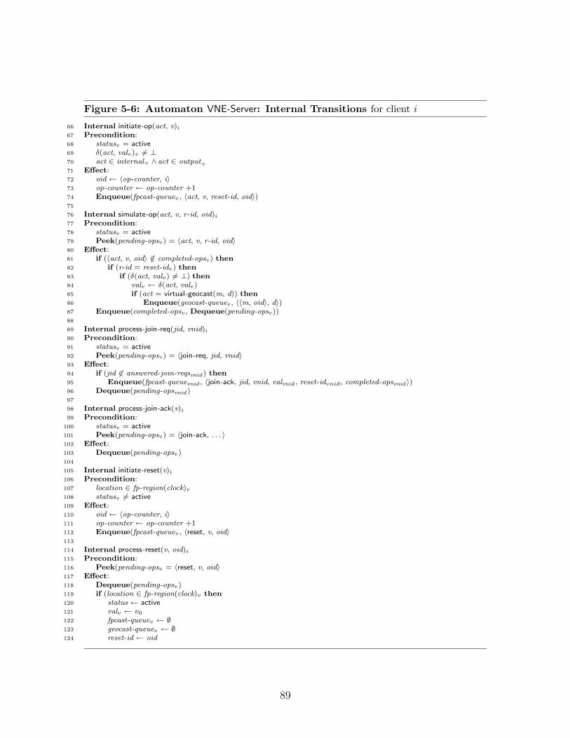
Figure 5-6: Automaton VNE-Server: Internal Transitions for client i
66 Internal initiate-op(act, v)i
67 Precondition:68 statusv = active69 δ(act, valv )v 6= ⊥70 act ∈ internalv ∧ act ∈ outputv71 Effect:72 oid ← 〈op-counter, i〉73 op-counter ← op-counter +174 Enqueue(fpcast-queuev , 〈act, v, reset-id, oid〉)75
76 Internal simulate-op(act, v, r-id, oid)i
77 Precondition:78 statusv = active79 Peek(pending-opsv ) = 〈act, v, r-id, oid〉80 Effect:81 if (〈act, v, oid〉 /∈ completed-opsv ) then82 if (r-id = reset-idv) then83 if (δ(act, valv ) 6= ⊥) then84 valv ← δ(act, valv )85 if (act = virtual-geocast(m, d)) then86 Enqueue(geocast-queuev , 〈〈m, oid〉, d〉)87 Enqueue(completed-opsv , Dequeue(pending-opsv))88
89 Internal process-join-req(jid, vnid)i
90 Precondition:91 statusv = active92 Peek(pending-opsv ) = 〈join-req, jid, vnid〉93 Effect:94 if (jid 6∈ answered-join-reqsvnid ) then95 Enqueue(fpcast-queuevnid , 〈join-ack, jid, vnid, valvnid , reset-idvnid, completed-opsvnid 〉)96 Dequeue(pending-opsvnid )97
98 Internal process-join-ack(v)i
99 Precondition:100 statusv = active101 Peek(pending-opsv ) = 〈join-ack, . . . 〉102 Effect:103 Dequeue(pending-opsv)104
105 Internal initiate-reset(v)i
106 Precondition:107 location ∈ fp-region(clock)v108 statusv 6= active109 Effect:110 oid ← 〈op-counter, i〉111 op-counter ← op-counter +1112 Enqueue(fpcast-queuev , 〈reset, v, oid〉113
114 Internal process-reset(v, oid)i
115 Precondition:116 Peek(pending-opsv = 〈reset, v, oid〉117 Effect:118 Dequeue(pending-opsv )119 if (location ∈ fp-region(clock)v then120 status ← active121 valv ← v0
122 fpcast-queuev ← ∅123 geocast-queuev ← ∅124 reset-id ← oid
89

Figure 5-7: Automaton VNE-Server: Output Transitions for client i
126 Output fpcast(〈m, fpcast-count, i〉)v,i
127 Precondition:128 Peek(fpcast-queuev ) = m129 Effect:130 fpcast-count ← fpcast-count +1131 Dequeue(fpcast-queuev )132
133 Output geocast(m, d)i
134 Precondition:135 v ∈ O136 Peek(geocast-queuev ) = 〈m, d〉137 Effect:138 Dequeue(geocast-queuev )
90

• The clock and the location variables store the time and location informationfrom the most recent geo-update.
• The status determines whether the emulator is currently participating in theemulation as a replica, joining the emulation, or idle.
• The value val stores the current state of the replica.
• The join-id is a unique identifier selected and used during the join protocol.
• The fpcast-queue and geocast-queue are two queues storing outgoing messagesfor the respective broadcast services.
• The answered-join-reqs is a set indicating which join requests have already beenanswered.
• The queue pending-ops stores messages waiting to be processed.
• The queue completed-ops stores messages that have already been processed.
• The counter fpcast-cnt is used to ensure that each fpcast message is unique1.
• The counter op-counter is used when simulated internal and output events toassign a unique identifier to each event.
• The identifier reset-id is used to uniquely identify each time the virtual node isreset.
For many of these state elements, the emulator maintains one copy for each v ∈ O.For example, if v1 and v2 are two different virtual nodes, there exists state elementspending-opsv1
and pending-opsv2. Each element is used only in the emulation of the
specified virtual node. Some, such as the clock , location, fpcast-count , and op-counterare used in the emulation of all the virtual nodes. This distinction is not critical; theelements are not duplicated when it is clear that this causes no additional complica-tions.
Joining and Leaving the Emulation. The emulator transitions between threestatuses: idle, joining, and active. We first discuss how a mobile node joins the emu-lation. The join protocol is activated when the mobile node enters the inner regionof a focal point v, i.e., when it hears that it is well inside the focal point region. Inthis circumstance, the join transition is enabled (Figure 5-6, lines 57–64). This resultsin the mobile node broadcasting a join-request message using the fpcastv service, atwhich point it sets its status to joining and awaits a response.
The other active nodes in the focal point receive the join request (Figure 5-5,lines 1–7) and respond by sending the current replicated state of the virtual object
1Up until this point, the emulator state has been equivalent to that of the VOE-Server. Theremaining elements are specific to the VNE-Server
91
using the fpcastv service (Figure 5-6, lines 89–96). Notice that this is slightly differentthan in the case of the Virtual Object Emulator, as the join request is processed inthe order received using the pending-ops queue. This is due to the need in this caseto order the join request with respect to reset messages that may reset the virtualnode.
As an optimization to avoid unnecessary message traffic, if a node observes (byexamining answered-join-reqs) that someone else has already responded to a joinrequest, then it does not respond; only one node needs to send a join response.Notice (Figure 5-5, line 91) that only active nodes will send join responses. Whenthe node that originated the join request receives its own join request (Figure 5-5,lines 4–5), it sets its status to listening.
When the joining node receives a response to its join request (Figure 5-5, lines 9–20), it starts participating in the emulation, setting its status to active. This completesthe join protocol.
By contrast, ceasing to participate in the emulation does not require any coor-dination with other replicas. When a node hears that it has left the inner focalpoint region (either due its own motion, or the movement of the virtual node), itre-initializes its variables, and becomes idle (Figure 5-5, lines 43–55).
Simulating Input, Output, and Internal Actions. We next discuss how ac-tive replicas simulate the virtual node’s transitions. When a node participating inemulating virtual node v receives a GeoCast message containing a message to deliverto virtual node v (Figure 5-5, lines 36–41), it broadcasts a proposal that the virtualnode simulate a virtual-geocast-rcv of that message; it broadcasts this proposal usingthe fpcastv service, thus ordering the virtual-geocast-rcv event for that message withrespect to the other messages broadcast with the fpcastv service (i.e., join-requestmessages, join responses, and other virtual node transitions). Notice that this pro-posal includes the identifier for the most recent reset, i.e., the reset-id , which allowsnodes receiving the proposal to determine whether the virtual node was reset betweenwhen the transition was proposed and when it was received. (This is different fromthe Virtual Object Emulator, which does not include resets.)
Since it is possible that a GeoCast message is received—and hence rebroadcast—by more than one node in the focal point, there is some bookkeeping to ensure thatonly one copy of the same invocation is actually processed by the nodes. We includean optimization that if a node observes via the pending-ops or completed-ops queuesthat an invocation has already been sent by the fpcastv service, then it does not doso again.
Replicas also simulate other types of transitions that the virtual nodes may exe-cute, that is, its locally controlled actions. (This is different from the Virtual ObjectEmulator, which only needs to process operation invocations.) At any time, a replicamay examine its local state and determine that some particular locally-controlledaction is enabled. In this case, it broadcasts a proposal using the fpcastv service sug-gesting that this transition be executed (Figure 5-6, lines 66–74). Again, notice thatthe proposal includes the reset-id .
92

Active nodes keep track of messages received via the fpcastv service in the order inwhich they are received (Figure 5-5, lines 22–28); this orders the various input, output,and internal actions to be simulated for virtual node v. Duplicates are discardedusing the unique operation identifiers, which are stored in the sets pending-ops andcompleted-ops . The transitions are then simulated (Figure 5-6, lines 76–87) on thereplicated state in this order, as long as the reset-id included in the proposal matchesthe reset-id of the emulator. Specifically, for input actions (e.g., virtual-geocast-rcvtransitions), the transition is always simulated, since input actions are always enabled.For internal and output actions, the transition is simulated if it is still enabled. Notice,though, that it is possible that intervening events might have disabled this transitionafter it was originally proposed, and hence it cannot be simulated. Whenever a replicasimulates a virtual-geocast of some message m, the replica adds the message m to itsoutgoing geocast-queue, resulting in the GeoCast of the specified message (Figure 5-6,line 86).
There are some subtle points involved in deciding when during the process of join-ing the emulation a node should start recording invocation messages, when a nodeshould start executing operations, and when a node should start sending responses.During the process of joining, a node receives a snapshot of the object’s state. How-ever by the time the snapshot is received, it might be out of date, since there mayhave been some intervening messages delivered by the fpcastv service that have beenreceived since the snapshot was sent. Therefore the joining node must record allthe operation invocations that are broadcast after its join request was broadcast butbefore it receives the snapshot. This is accomplished by having the joining node en-ter a “listening” state once it receives its own join-request message; all invocationsreceived when a node is in either the listening or the active state are recorded, andactual processing of the invocations can start once the node has received the snap-shot and has the active status. The processing consists of first emptying the queueof waiting invocations, and then proceeding to handle newly arrived invocations.
A final point to notice is that every message sent by the fpcastv service is unique:attached to each message is a counter (fpcast-cnt) and the process identifier; eachprocessor increments its counter after each fpcast, ensuring that no message is dupli-cated. Notice that each message m that is fpcast is of the form 〈P, cnt , k〉, where cntis a counter and k is a node identifier. We refer to P as the payload of m.
Resetting the Virtual Node. Sometime, particularly when the virtual node hasfailed due to depopulation, it may be useful for the virtual node to reset itself. Inparticular, if a node does not receive a response during the join protocol, it caninitiate a reset (Figure 5-6, lines 105–112). In this case, it broadcasts a reset messageusing the fpcast service. This reset message contains a unique identifier that is usedto name each successful reset event. Each proposed transition for the virtual nodeincludes the identifier of the most recent reset; if a more recent reset has occurred inthe interim since the transition was proposed, then the proposal is ignored.
When a node receives a reset message, if it is well inside the focal point region,then it processes the reset message in order from the pending-ops queue, sets its status
93
to active, and resets its emulator state, including the replicated state val of the virtualnode.
5.2 Analysis: Safety of the Emulation
In this section we show that the Virtual Node Emulator ensures a safe emulation ofthe Virtual Node Layer, meaning that every trace of the emulator, when restrictedto the clients actions, is a trace of the Virtual Node Layer. The performance of theemulator is considered separately in Section 5.3. We begin be reviewing what it meansfor the protocol to ensure a safe emulation.
For each i ∈ I, let ci be a client automaton, and let C be the composition of allthe client automata. Let Av be a virtual node automaton, specifically, the automatondesignated to execute on virtual node v. When describing Av, let δv be the transitionrelation associated with automaton Av. Recall that automaton Av is deterministic,and hence for every state s and every action a, there is at most one state s′ such that〈s, a, s′〉 ∈ δv.
Let S be the physical system consisting of the client automata ci, each composedwith (1) a VNE-Client automaton and (2) a VNE-Server automaton. Let U rep-resent the environment, i.e., the RealWorld automaton containing the geocast andfpcastv services. Thus the automaton S×U describes the underlying physical systemexecuting a set of clients along with the Virtual Node Emulator.
Recall that the virtual node layer consists of three types of automata: clients,virtual nodes, and the RealWorld automaton, containing the virtual GeoCast service.Let S ′ be the subsystem of the Virtual Node Layer consisting of the set of clientsci, and the set of virtual nodes O. Let U ′ be the virtual RealWorld automaton,which includes the virtual GeoCast service. Thus the automaton S ′ × U ′ describesthe Virtual Node Layer.
We want to show that every trace of S×U , when restricted to the external actionsof the clients C, is a trace of S ′ × U ′, restricted to the external actions of the clientsC. (Recall that a trace is a timed sequence of externally-visible events.) Formally,we first define a set H containing all the hidden actions in S×U : let H be the entireset of externally-visible actions for S×U , excluding the externally-visible actions forC. Similarly we define a set H ′ containing all the hidden actions in S ′×U ′: let H ′ bethe entire set of externally-visible actions in S ′ × U ′, excluding the externally-visibleactions for C.
We say that the emulation is safe if for every admissible execution α of S × U ,there exists an execution γ of S ′ ◦ U ′ such that
trace(hideH′(γ)) = trace(hideH(α)) .
In this case, the clients cannot distinguish whether they are executing in the virtualsystem or the real system.
For the purpose of this section, fix an arbitrary admissible execution α of systemS×U . The goal of this section is to demonstrate an execution γ of S ′×U ′ satisfying
94

the requisite trace indistinguishability.
We first construct individual executions for the components of system S ′, thatis, the clients (Section 5.2.1) and virtual nodes (Section 5.2.2). These individualexecutions are constructed independently, based on the execution α of the underly-ing physical system. We then construct a trace of the composed system S ′ that isconsistent with each of the individual executions (Section 5.2.3). Finally, we invokea pasting lemma to construct a single execution of the composed system S ′ (Sec-tion 5.2.4). The resulting execution defines the behavior of the clients and virtualnodes in the virtual system.
It remains to consider the virtual RealWorld automaton and the behavior of thevirtual GeoCast service, i.e., U ′ (Section 5.2.5). Recall that the virtual RealWorldautomaton is defined as an automaton that produces every trace satisfying integrity,while maintaining the real time and the location of each client, along with a restrictionon traces that guarantees reliable delivery. To this point, we have constructed anexecution γS′ of system S ′; this execution implies a trace of the virtual RealWorldautomaton (and the virtual GeoCast service) U ′. We show that this trace satisfiesthe integrity property, and thus that there is an execution of U ′ consistent with thistrace. A second invocation of the pasting lemma produces an execution γ of the entirevirtual system S ′ × U ′, and completes the proof that the emulation is safe.
5.2.1 Client Executions
We begin by constructing an execution γi for each client i ∈ I. Specifically, we defineγi to be the restriction of α to the actions of client i. Formally, let actions i be theset of actions for client ci; then γi = α|actions i.
5.2.2 Virtual Node Executions
We now construct an execution γv for each virtual node v ∈ O. For the rest ofSection 5.2.2, fix some virtual node v ∈ O.
First, we define a set of events IM (α)v that occur in execution α. Second, wedefine a total order on these events. Third, we construct an execution of virtual nodev derived from this total order.
We then show an important property of this execution: the state of each replica ateach point in α reflects exactly the events described in IM (α)v as ordered accordingto the total order that we have defined in this proof. This construction and this proofis analogous to the construction in Sections 4.2.1 and 4.2.2.
Defining the Set of Operations. For execution α, let IM (α)v be the set of eventsfor virtual node v simulated by the VNE-Server automata, along with the set of resetevents. Specifically:
IM (α)v = {〈act, v, oid〉 : ∃j ∈ I such that simulate-op(act, v, oid)j occurs in α }∪ {〈reset, v, oid〉 : ∃j ∈ I such that process-reset(v, oid)j occurs in α } .
95
Thus, for each operation simulated in α and for each reset event, there is one element〈act, v, oid〉 in the set IM (α)v.
Defining a Total Order. Notice that each element in the set IM (α)v is associatedwith at least one message m = 〈〈act, v, oid〉, ·, j〉 or m = 〈〈reset, v, oid〉, ·, j〉 where forsome j ∈ I there is an fpcast(m)j event in α: the precondition of simulate-op ensuresthat each simulated event is drawn from the queue pending-opsv; the precondition ofprocess-reset also ensures that each reset event is drawn from the queue pending-opsv.This queue is populated with messages received from the fpcastv service. We say thatan event 〈act, v, oid〉 is associated with some message m if the event can be traced tothe reception of message m, which added the event to the pending-opsv queue, andthen was processed/simulated.
The total-ordering property of the fpcastv service guarantees that, since everyfpcast message is unique, there exists a total ordering of the messages that is consistentwith the order in which each mobile node receives the messages. That is, if node ireceives two messages mr and mt in that order, then mr ≺ mt in the total ordering.Thus, we order the events in IM (α)v according to the total ordering on their associatedmessages: fix ≺v to be this ordering. (We will drop the subscript v where it is clearby context that we are referring to messages from this particular fpcastv service.)
Defining an Execution. We define execution γv based on the events in IM (α).We first construct a non-timed version of γv inductively as is described in Figure 5-8,and then we insert appropriate time-passage events. In this construction, we iterateover the messages in IM (α)v, considering the messages that represent either an actionfor v or a reset request. We apply these actions/resets in the specified total order,omitting those that are not enabled, and inserting fails before recoveries.
More formally, we proceed as follows. For each message proposing an action, ifthat action is enabled, we add a transition in δv to the end of the execution; thatis, we apply the action to the state at the end of the execution. Since the virtualnode is deterministic, we can uniquely identify the behavior of each action. For eachmessage proposing a reset, we add a fail transition to the end of the execution; thatis, we apply a fail action to the state at the end of the execution. We then add a resetaction, which returns the virtual node to its initial state. Finally, if there are no moremessages to consider, and if in execution α there are eventually no active emulators,then we add a final fail event to the end of the execution. Notice also that for eachmessage proposing a virtual-geocast-rcv for some message m with an associated uniqueidentifier u, we consider only the first such message.
To this point, there are no trajectories in execution γv. For each event in γv we fixa time at which that event occurs, and then add appropriate trajectories in betweenthe discrete events. Specifically, for each event e in γv that was added as a resultof a simulate-op event in α, associate event e with the time at which the first suchsimulate-op event occurs in α. For each reset event e in γv, associate with event e thesame time as the process-reset event in α that resulted in the reset event being addedto the execution. For each fail event e in γv, associate with event e the same time as
96

Figure 5-8: Construction of Virtual Node Execution γv
1. Initially, set γv = s0, the initial state of virtual node v.
2. Define the set S as follows:
S = {〈P, cnt , k〉 : P ∈ IM (α)v, and
〈P, cnt , k〉 is the fpcast message associated with P} .
3. Repeat while S 6= ∅:
(a) Let m be the minimum message in S, according to the total order ≺v.
(b) If m = 〈〈act , v , oid〉, ·, ·〉 then:
• Let s be the last state in γv.
• If there exists some state s′ such that 〈s, act , s′〉 ∈ δv, i.e., if actionact is enabled, then choose the unique s′ such that this condition issatisfied and append act .s′ to γv.
(c) Else if m = 〈〈reset, v, oid〉, ·, ·〉 then:
• Let s be the last state in γv.
• Choose the unique s′ such that 〈s, fail, s′〉 ∈ δv. (Recall that inputactions are always enabled.)
• Choose s′′ = v0.
• Append fail.s′.reset.s′′ to γv.
(d) If m represents a virtual-geocast-rcv event, remove from S every messagem′ that proposes the identical virtual-geocast-rcv, as identified by the as-sociated unique identifier.
4. If S = ∅ and at some point in execution α after the last event in S there doesnot exist any i ∈ I such that statusv,i = active, then add a failv to the end of γv.
97

the event preceding it in γv.
5.2.3 Constructing the Trace
Next, we construct a hybrid sequence β of externally-visible actions by the clientsand virtual nodes, i.e., of externally-visible actions of S ′. (Recall we are postponingconsideration of the virtual RealWorld until Section 5.2.5.) We show that β is a traceof S ′, and use it to align the various component executions. As a result, β enables usto paste together the various component executions in a single execution of S ′.
More formally, we construct a sequence β such that the following properties holds:
• For all i ∈ I, let external i be the externally visible actions of client i. For alli ∈ I, β|external i = trace(γi).
• For all v ∈ O, let externalv be the externally visible actions of virtual node v.For all v ∈ O, β|externalv = trace(γv).
As a result, the trace β is consistent with the individual component executions.In order to construct this trace, we begin with a trace of the physical system, i.e.,
a trace of α. We exclude from this trace all the events that are not relevant to clientsand virtual nodes, and then substitute some virtual node events for certain emulatorevents.
More specifically, let β be the trace of α containing all the externally visible clientevents, i.e., external i for all i ∈ I. Also, temporarily, include in β all the simulate-opevents and process-reset events as well. (We will remove these events after the nextstep.) Formally, then, let:
E = {external i : i ∈ I}∪ {simulate-op(act , v, oid)i : act ∈ actions [v], v ∈ O, oid ∈ U, i ∈ I}∪ {process-reset(v, oid)i : oid ∈ U, i ∈ I}
and let β = α|〈E, ∅〉.It remains to add the virtual node events, and to remove the simulate-op and
process-reset events. For each virtual node v, we add the externally visible eventsfrom γv to β as follows:
Let e be some externally-visible event from γv. If e is not a failv event or a resetv,then by the construction of γv, for some j ∈ I, there is a simulate-op(e, v, oid)j event inIM (α)v, and hence in α, that led to event e being added to γv. In this case, add evente to β immediately after—and with no time passage—as the first simulate-op(e, v, oid)event in β.
If e is a failv event followed by a resetv event, then by the construction of γv, forsome j ∈ I, there is a process-reset(v, oid)j event in IM (α)v, and hence in α, thatled to event e being added to γv. Let e′ be the first process-reset(v, oid)j event in β,and let e′′ be the event immediately preceding e. Add a failv event immediately afterevent e′′ with no time passage between event e′′ and the fail event. Add a resetv eventto β immediately after event e′ with no time passage between e′ and the reset event.
98

If e is a resetv event, notice by the construction of γv that it is immediatelypreceded by a failv event, and hence is covered by the previous case.
If e is a failv event that is not followed by a resetv event, then add it to β afterall the other events from γv at a point corresponding to the first point in α afterthe other events in γv at which there does not exist a i ∈ I where status i,v = active.Since such a failv event is always the last event in γv, placing it at this point is clearlyconsistent with the other events in γv. Assign it the same time as its immediatelypreceding event.
Finally, remove all the simulate-op events and process-reset events from β. Theresulting trace is clearly consistent with the client executions, as both β and the clientexecutions are constructed directly from a restriction of α. It is also consistent withthe virtual node executions since every external event in γv is added to β, and theyare added in the same order and at the same time, i.e., the order of the simulate-opand process-reset events.
5.2.4 Pasting Executions
Next, we invoke a pasting lemma to combine the various component executions togenerate an execution of S ′. In Section 5.2.5, we construct an execution of U ′ andperform a second pasting step to produce an executino of S ′ × U ′, i.e., an executionof the Virtual Node Layer.
We begin by stating a basic lemma related to execution-pasting, which is anextension of Theorem 7.3 from [45,46]:
Lemma 5.2.1. Let A1 and A2 be compatible timed automata, and A = A1×A2. Letα1 and α2 be executions of A1 and A2, respectively.
Let β be an (E, ∅)-sequence, where E is the set of external actions of A. Supposethat β|(Ei, ∅) = trace(αi), i ∈ {1, 2}.
Then there exists an execution α of A such that trace(α) = β, and αi = α|(Ai, Xi),i ∈ {1, 2}.
It follows that we can paste together a countable collection of components:
Corollary 5.2.2. Let A1, A2, . . . , Ak be a finite collection of compatible timed au-tomata, and let A = A1 × A2 × . . . Ak. Let αi be an execution of Ai.
Let β be an (E, ∅)-sequence, where E is the set of external actions of A. Supposethat β|(Ei, ∅) = trace(αi), i ∈ {1, 2, . . . , k}.
Then there exists an execution α of A such that trace(α) = β, and αi = α|(Ai, Xi),i ∈ {1, 2, . . . , k}.
Using Corollary 5.2.2, we can paste together all the various components’ execu-tions that we have constructed in the preceding sections:
• γi, i ∈ I, the clients, and
• γv, v ∈ O, the virtual nodes.
Define γS′ to be the execution of S ′ resulting from pasting together these variousautomata. We now proceed in the following section to consider U ′.
99
5.2.5 RealWorld / Virtual GeoCast Execution
In this section, we construct an execution of U ′, the RealWorld automaton (andthe virtual GeoCast service) and again invoke the pasting lemma to construct anexecution γ of S ′ × U ′. We construct the execution of U ′ as follows: first we noticethat we can derive a trace βU ′ of U ′ from execution γS′ , since every external actionof U ′ is shared with S ′. We show that this hybrid sequence βU ′ satisfies the integrityproperty, and that the geo-updates to the clients occur sufficiently frequently. By thedefinition of the virtual RealWorld automaton, there exists an execution of U ′ thatis consistent with this sequence. We then invoke Lemma 5.2.1 to construct executionγ.
The key claim in this section is that the sequence βU ′ satisfies the integrity prop-erty, implying that it is a trace of the virtual RealWorld automaton. We show thatfor every virtual-geocast-rcv(m, d)k event in βU ′ of U ′, there is a preceding virtualgeocast, i.e., virtual-geocast(m, d)`. Notice that nodes k and ` can be either clients(identified by the set I) or virtual nodes (identified by the set O). The proof of thisintegrity property follows the same structure as Section 4.2.2, and the main claim,Invariant 5.2.3, is similar in structure to Invariant 4.2.1.
Defining the sequence. We begin by defining the sequence βU ′ of the RealWorld/-GeoCast automaton. Recall that we have already determined an execution β of ex-ecution γS′ in Section 5.2.3. We begin with the trace β and restrict to the set ofexternally-visible actions of the virtual RealWorld. Formally, let:
Egeo = {virtual-geocast(m, d)k : m is a message, d ∈ R, k ∈ I ∪O}∪ {virtual-geocast-rcv(m, d)k : m is a message, d ∈ R, k ∈ I ∪O}∪ {failv : v ∈ O}∪ {faili : i ∈ I}∪ {resetv : v ∈ O}∪ {geo-update(t, `)i : t ∈ R, ` ∈ L, i ∈ I}
and let βU ′ = β|〈Egeo, ∅〉. Our goal is to show that β′ satisfies the integrity property,and hence that there exists an execution of U ′ with trace βU ′ .
Defining partial executions. We now define partial executions that reflect theoperations known to a given replica. For every prefix α′ of α, for every i ∈ I, defineγ(α′, v, i) as follows. We first construct an asynchronous execution, as in Figure 5-8,and then assign a time to each event. Define γ(α′, v, i) as is described in Figure 5-9.First, choose message m to be the largest message received by i via the fpcastv servicein α′ that is not in `state(α′).pending-opsv,i. The construction proceeds exactly as inFigure 5-8, with the exception that we only consider messages that precede m. Thatis, we iterate over the messages in IM (α)v that precede m, considering the messagesthat represent either an action for v or a reset request. We apply these actions/resetsin the specified total-order, omitting those that are not enabled, and inserting fails
100

Figure 5-9: Defining Partial Execution γ(α′, v, i)
Choose m to be the largest message received by i via the fpcastv service in α′ that isnot in `state(α′).pending-opsv,i.
1. Initially, set γ(α′, v, i) = s0, the initial state of virtual node v.
2. Define the set S as follows:
S = {〈P, cnt , k〉 : P ∈ IM (α)v,
〈P, cnt , k〉 is the message associated with P, 〈P, cnt , k〉 ≤ m} .
3. Repeat while S 6= ∅:
(a) Let m be the minimum message in S, according to the total order ≺v.
(b) If m = 〈〈act , v , oid〉, ·, ·〉 then:
• Let s be the last state in γ(α′, v, i).
• If there exists some state s′ such that 〈s, act , s′〉 ∈ δv, i.e., if actionact is enabled, then choose the unique s′ such that this condition issatisfied and append act .s′ to γ(α′, v, i).
(c) Else if m = 〈〈reset, v, oid〉, ·, ·〉 then:
• Let s be the last state in γ(α′, v, i).
• Choose the unique s′ such that 〈s, fail, s′〉 ∈ δv. (Recall that inputactions are always enabled.)
• Choose s′′ = v0.
• Append fail.s′.reset.s′′ to γ(α′, v, i).
(d) If m represents a virtual-geocast-rcv event, remove from S every messagem′ that proposes the identical virtual-geocast-rcv, as identified by the as-sociated unique identifier.
101
before recoveries.
Notice that the sequence constructed by Figure 5-9 is necessarily a prefix of thesequence constructed by Figure 5-8: both constructions follow an identical process,but the former considers only messages that precede some message m (including mitself) in the ordering inducted by the fpcast service.
We therefore assign a time to each event in a manner that matches γv: if someevent e occurs in (γ(α′, v, i)), then it also occurs in γv; assign event e the same timein the former as it has in the latter. Notice, then, the following observation:
Observation 1. For every α′ < α, for every i ∈ I: γ(α′, v, i) is a prefix of γv.
This follows since the partial execution γ(α′, v, i) is defined by set S which is aprefix of the (ordered) set of events IM (α)v.
Notice that every reset event in γ(α′, v, i), for any α′ and i, is associated with some〈reset, v, oid〉 message received in α′. We refer to oid as the reset identifier for sucha reset event.
The main invariant. We now proceed to show that for every i ∈ I, the executionγ(α′, v, i) reflects exactly the state of replica i at the end of α′. In particular, weshow that for every active replica i, the replica state val v,i is equal to the last state
in γ(α′, v, i) at the end of every prefix α′.
Invariant 5.2.3. Let execution α′ be a finite prefix of execution α, and mobile nodei ∈ I. If `state(α′).statusv,i = active, then `state(α′).valv,i = `state(γ(α′, v, i)).
Proof. We show this by induction on the length of α′. Throughout the induction, wealso maintain two further invariants. The first, Invariant 5.2.4, show that an activereplica is aware of the entire history since the most recent reset event. Notice that foreach fpcast-rcv(m) event, message m = 〈P, cnt , k〉, i.e., consists of some P , which werefer to as the payload, along with two further parameters that ensure each messageis unique.
Invariant 5.2.4. For all j ∈ I, if the following conditions hold for some prefix α′
of α:
• `state(α′).statusv,j = active,
• message m is the largest message such that a fpcast-rcv(m)v,j occurs in α′,
• message m′ is the largest message ≤ m such that m′ = 〈〈reset, v, ·〉, ·, ·〉, orm′ = ⊥ if there is no such message;
then for every message m′′ : m′ < m′′ ≤ m that is received in α via a fpcast-rcvv,j′
for j′ ∈ I where m′′ = 〈P, ·, ·〉, the payload P is in `state(α′).pending-opsv,j ∪`state(α′).completed-opsv,j.
102

The second, Invariant 5.2.5, shows that the the reset-id of a replica correctly tracksthe most recent reset identifier. This is used to ensure that a replica only processesoperations that have occurred since the last reset. Together with Invariant 5.2.4,this ensures that each operation is only executed once: operations prior to the mostrecent reset are ignored, and operations since the most recent reset are available inthe history of completed-ops .
Invariant 5.2.5. For all j ∈ I, if for some prefix α′ of α:
• `state(α′).statusv,j = active,
• e is the last reset event in α′, and
• oid is the reset identifier of e;
then `state(α′).reset-idv,j = oid. If no such event e exists in execution α′, then:
`state(α′).reset-idv,j = 〈i0,−1〉 .
For the base case, consider the initial state of the system, before any events occurin α. Let γpost be this empty prefix of α. If i is not in the focal point region, thenstatusv,i = idle, and the claim is trivial. If i is in the focal point, then the state of valv,i
is v0, the initial state of virtual node v. Since i has received no messages, γ(γpost , v, i)is also the empty execution, satisfying the main invariant. Invariant 5.2.4, for thebase case, also follows immediately from the fact that there are no messages receivedin the empty execution. Similarly, for Invariant 5.2.5, γpost has no reset events, andevery node has reset-idv,j = 〈i0,−1〉 in its initial state, implying the desired condition.
There are two types of inductive steps to consider for executions of timed au-tomata: discrete events and trajectories. Notice that for trajectories, the invariantsare trivially maintained since all the state elements mentioned in the invariants arediscrete and unchanged under time passage. Consider, then, a discrete event.
Let s and s′ be the states before and after the new event, respectively. Let γpre
be the previous prefix of α ending in state s, that is, s = `state(γpre). Let γpost bethe new prefix of α after the new event, that is, s′ = `state(γpost).
We know, inductively, that for any finite prefix α′ of γpre , for any node j, if
`state(α′).statusj = active, then `state(α′).valj = γ(α′, v, j)), and also that Invari-
ant 5.2.4 holds. We need to show that `state(γpost).val v,i = γ(γpost , v, i), and thatInvariant 5.2.4 continues to hold. We now consider the different events that canoccur which modify the state relevant to the three invariants:
• fpcast-rcv(〈〈act , vnid , oid〉, ·, ·〉)v ,i: (Figure 5-5, lines 22–28.)This event adds 〈act, vnid , oid〉 to pending-opsv, if the status of i is active andif the operation is not already in pending-opsv or completed-opsv.
Recall that the execution γ(γpost , v, i) includes only messages that have beensimulated in γpost and precede the largest message received by i not in the setof pending operations, i.e., pending-opsv,i. There are three cases to consider:
103
– The event 〈act , vnid , oid〉 is already in pending-opsv,i. In this case, thestate of pending-opsv,i is not modified. The message m = 〈〈act , vnid , oid〉, ·, ·〉becomes the largest message received by i (in the total order); however,since m is already in pending-opsv,i, the message m that is used to define
γ(γpre , v, i) remains unchanged.
As a result, the execution γ(γpost , v, i) is equal to γ(γpre , v, i). By induction,
we already know that γ(γpre , v, i) = `state(γpre).val v,i. Since val v,i remainsunchanged, the claim follows.
– The event 〈act , vnid , oid〉 is not in pending-opsv,i or completed-opsv,i. Inthis case, the event 〈act , vnid , oid〉 is added to pending-opsv,i. As in theprevious case, the received message becomes the largest message receivedby i, but does not result in any changes to γ(γpre , v, i) since the messageis in pending-opsv,i.
– The event 〈act , vnid , oid〉 is in completed-opsv,i. In this case, the largestmessage received by i, as determined by the total ordering, remains un-changed: some message 〈〈act , vnid , oid〉, ·, ·〉 (from a different node) hasalready been received earlier in the ordering in order to be resident incompleted-opsv,i.
We next proceed to argue that Invariant 5.2.4 is maintained. If the message〈〈act , vnid , oid〉, ·, ·〉 is not the largest message received by i, then the situationis unchanged and Invariant 5.2.4 continues to hold by the inductive hypothesis.
Consider the case where message 〈〈act , vnid , oid〉, ·, ·〉 is the largest messagereceived by i from the fpcastv service in γpost . Let m′ be the largest messagereceived by i in γpre from the fpcastv service. We show that every messagem′′ : m′ < m′′ < m has its payload either in pending-ops or completed-ops .(Notice that this proves a property somewhat stronger than the necessary in-variant, as it does not exclude messages prior to a reset event that may occurbetween m′′ and m.)
Assume for the sake of contradiction that such a message m′′ exists whosepayload is not in either set. We argue that this implies that node i has exitedthe focal point region at some point after receiving message m′ and prior toreceiving message m: since every message received from the fpcastv service isadded to either pending-ops or completed-ops , and messages are removed onlywhen i exits the focal point region, there are two possible cases:
– Node i exits the focal point region at some point between receiving m andm′, and resets pending-ops during the geo-update, removing the payloadof message m′′ from pending-ops .
– Node i does not receive m′′. In this case, we conclude by the consistentdelivery property of the fpcastv service that i exits the focal point regionat some point between receiving m and m′.
104
In either case, i exits the focal point between receiving message m and m′,setting status i,v to idle. Moreover, it is easy to see that i does not reset itsstatus to active prior to receiving message m: we know that message m′ is themost recent message received by i prior to m (since it is the largest message inγpre), and hence i did not receive a join-ack between messages m′ and m. Thiscontradicts our assumption that status i,v = active.
Finally, consider Invariant 5.2.5: notice that this event has no effect either onthe reset events in execution γ(γpre , v, i), nor does it modify reset-id i,v; thereforethe invariant is maintained.
• simulate-op(act , v , r-id , oid)v,i: (Figure 5-6, lines 76–87.)First, when this event occurs, statusv,i = active, since that is a precondition tothis action (Figure 5-6, line 78). The event removes 〈act , v , oid〉 from the setpending-opsv,i, and thus the message m which originally caused this operationto be added to pending-opsv,i is now included in the construction of execution
γ(γpost , v, i); in particular, since m no longer refers to the largest message re-ceived by i and (no longer) in pending-ops , we can conclude that act is the lastevent in γ(γpost , v, i). By construction we can conclude that γ(γpost , v, i) includesevery operation specified by every message preceding m that is received in α.
There are two subcases to consider.
– Message m contains a payload 〈act , v, oid〉 included in another messagealready received and processed. That is, there exists a message deliveredearlier in the ordering with the same action, virtual node, and operationidentifier. In this case, γ(γpost , v, i) = γ(γpre , v, i), as the constructionincludes each payload only once. It remains to show that val v,i is alsounmodified as a result of the simulate-op event. If r-id 6= reset-id i,v, thenval v,i is unmodified as desired (Figure 5-6, line 82).
Assume therefore that r-id = reset-id i,v. By Invariant 5.2.5, we concludethat either there are no reset events in γpre , or r-id is the reset identifierof the most recent reset event in γpre . Let m′ = 〈〈reset, v, r-id〉, ·, ·〉 be themessage in IM (α′) associated with that reset event. Notice that messagem could not have been received and processed prior to message m′ as inthat case i would have a different reset-id and hence would reject messagem. Thus we are interested in the case where i has received some messagem′′ with the same operation identifier as m such that in the total orderingm′ < m′′ < m.
By induction, we know from Invariant 5.2.4 that every message m′′ : m′ <m′′ ≤ m that is received in α is in pending-opsv,i ∪ completed-opsv,i. Thus,the payload of the earlier message m′′ identifying the same operation asm is also in pending-opsv,i ∪ completed-opsv,i. We also know that it isnot in pending-opsv ,i since message m is the smallest—and hence oldest—message in pending-ops (as it is a queue); from this we conclude that theearlier message is in completed-opsv,i. In this case the simulated-op event
105

transition does not modify val v,i due to Figure 5-6, line 81, and the maininvariant is maintained.
– Message m refers to a new operation, in which case
γ(γpost , v, i) = δ(act , `state(γ(γpre , v, i))) .
By induction we know that val v,i = `state(γ(γpre , v, i)) in state s. Afterthe simulate-op transition, val v,i is set to δ(act , val v,i). This maintains thedesired invariant.
Since this event neither results in a new message being received from the fpcastvservice, nor removes any messages from pending-ops∪completed-ops (only mov-ing a message from one to the other), Invariant 4.2.2 is also maintained.
Finally, consider Invariant 5.2.5: notice that this event has no effect either onthe reset events in execution γ(γpre , v, i), nor does it modify reset-id i,v; thereforethe invariant is maintained.
• fpcast-rcv(〈〈join-ack, jid, v, c-ops〉, ·, ·〉)v,i: (Figure 5-5, lines 9–20)In this event, node i sets statusv,i to active (Figure 5-5, line 14), if the messageis a response to an outstanding join-req previously sent by i. (If this is not thecase, then this action causes no change to statusv,i, pending-opsv,i, reset-idv,i, orval v,i, and adds the message to completed-psv,i; thus the invariants are triviallymaintained.)
The fpcastv service guarantees that if a message is received, an earlier fpcastoccurred at some node j that sent the message (that is, it guarantees messageintegrity). In particular, some node j previously performed a
fpcast(〈join-ack, jid, v, val, r-id , c-ops〉)j .
The only action that causes a join-ack to be sent is a prior join request being re-ceived . Therefore, node j previously performed an fpcast-rcv(〈join-req, jid, v〉)v,i.Let γ′′ be the prefix of γpre ending with the fpcast-rcv(〈join-req, jid, v〉)j event.
Consider the state of node j at the end of γ′′. First, the status, statusv,j,must be active; otherwise node j would not send a response to the join request(Figure 5-6, line 91). Inductively, then, we know that `state(γ′′).val v,j is equal
to `state(γ(γ′′, v, j)). Thus, we can conclude that val , the value sent from j toi, is also equal to `state(γ(γ′′, v, j)). By Invariant 5.2.5 we can conclude that`state(γ′′).reset-idv,j identifies the most recent reset in γ(γ′′, v, j).
Since val v,i is set to val when the join-ack message is received, i.e., during thetransition in question, it remains only to show that:
γ(γpost , v, i) = γ(γ′′, v, j) , (5.1)
and we can conclude that val v,i = `state(γ(γpost , v, i)), as desired. From this we
106
will also conclude that the reset identifier r-id included in the join-ack message isthe most recent reset identifier for γ(γpost , v, i), thus maintaining Invariant 5.2.5.
Let m be the largest message that is received by i via the fpcastv service in γpost
whose payload is not in s′.pending-opsv,i, that is, m is the message used in the
construction of γ(γpost , v, i). We claim that m must correspond to node i’s joinrequest, which implies Equation 5.1, as it is easy to see that i’s join request isthe message used in the construction of γ(γ′′, v, j): i’s join request is the lastmessage received by j and removed from pending-opsv,j prior to sending thejoin-ack message.
First, we know that i has already received its own join request in γpost : i setsits status to active only if it has previously received its own join request andset its status to listening. Moreover, i does not add its own join request topending-msgs and hence we can conclude that m is no smaller that i’s joinrequest.
Second, notice that when i receives its own join request, it sets its status tolistening and when i’s status is listening, it adds every message it receives (afterits own join request) to pending-opsv,i (Figure 5-5, line 5). No message is re-moved from the set pending-opsv,i because statusv,i is not yet active (Figure 5-6,line 78). Therefore m cannot be equal to any message received by i after i’sown join request.
We conclude, then, that m is exactly i’s join request. Recall that the executionγ(γpost , v, i) is defined as including all the simulated messages prior to m, thatis, prior to i’s join request.
Notice that i’s join request is exactly the last message processed by j in γ′′ beforesending a response to i. In particular, then, γ(γ′′, v, j) is the execution includingevery operation in IM (γ′′) prior to i’s join request. Therefore, Equation 5.1holds, and the invariants holds in state s′.
We next argue that Invariant 4.2.2 is also maintained. Notice that when nodej sends the join-ack message, it also includes a copy of its set completed-opsv ,j ,and that at this point in the execution, Invariant 4.2.2 holds with respect to j;this means that the payload of every message preceding node i’s join requestand after the most recent reset is in pending-opsv,j ∪ completed-opsv,j. Sincepending-opsv,j is a queue, and since when responding to a join request, allpayloads from preceding messages have been removed from pending-opsv,j, wecan conclude that the payload of every message preceding the join request isin completed-opsv,j. When node i receives the join-ack, it adds all the messagepayloads in the set c-ops to its own set completed-opsv,i. It remains only toshow that every message payload sent after i’s join request is in pending-opsv,i.This follows immediately from the fact that i has remained in the focal pointregion, and the consistent delivery property of the fpcastv service.
• process-join-req(jid , vnid i: (Figure 5-6, lines 89–96)In this case, a join-req message is removed from pending-opsv,i, which potentially
107

indicates that γ(γpost) 6= γ(γpre).
In fact, the virtual execution prefix is unmodified. Let m be the join-req message〈join-req, jid , vnid〉 that precipitated this event. Let m be the largest messagereceived by i via the fpcast service in γpre that is not in pending-opsv,i at the
end of γpre , i.e., the message that is used to define γ(γpre). We argue that thereare no intervening messages in IM (α) between m and the join-req message m.
Assume for the sake of contradiction that such an intervening message m′ ∈IM (α) exists where m < m′ < m. Choose m′ to be the largest such message.By the consistent delivery property of the fpcast, either i receives message m′,or i leaves the focal point point between receiving m and m. In the latter case,however, i sets statusv,i to idle; by assumption (i.e., the choice of m) there isno intervening message in γpre that causes i to reset its status to active, thuscontradicting our assumption that i is active. We thus conclude that i receivesmessage m′. By the choice of m this implies that m′ is in pending-opsv,i, whichcontradicts the fact that messages are processed in order and hence m′ wouldhave been processed prior to m.
Finally, we notice that message m is not in IM (α), as it is a join request, andthere are no intervening messages between overlinem and m that are in IM (α),and hence the virtual execution prefix is unmodified.
• process-join-ack(v)i: (Figure 5-6, lines 98–103)In this case, a join-ack message is removed from pending-opsv,i. The argumentis identical to the previous case.
• process-reset(v, oid)i: (Figure 5-6, lines 114–124)In this case, the virtual node is reset. In the case where the replica is not in thefocal point, the invariants are trivially maintained since the status of i is idle.We thus assume that i is in the focal point and hence executes the reset code.
Let m be the 〈reset, v, oid〉 message that leads to this event. Since messagesare processed in order, it is clear that m is the largest message received by ithat is not in pending-opsv,i. Thus the last event in γ(γpost , v, i) is a reset event,and hence the final state is v0, the initial state. Similarly, after the process-resetevent, val v,i = v0, and thus the main invariant is maintained.
Similarly, Invariant 5.2.4 is maintained since every message received after mremains in pending-opsv,i. (The consistent delivery property ensures that thereare no gaps in the sequence of received messages.) Messages prior to m are nolonger relevant since m is a reset event.
Finally, Invariant 5.2.5 is maintained since this event updates reset-idv,i to oid ,which is the reset identifier for this reset event.
The rest of the cases are straightforward, having no effect on the status of i, thestate of the replica, or the reset-id ; moreover, every other fpcast message is added tocompleted-ops or pending-ops , and no elements are removed (except when i exits thefocal point region).
108
Relating states to executions. Our goal now is to show that the execution γv
constructed for virtual node v is consistent with the simulation performed by eachreplica, i.e., by each VNE-Server automaton. We have already shown that the stateof each replica is consistent with the partial executions; we now show that this isconsistent with γv as well. This follows primarily from the fact that each partialexecution is a prefix of γv.
In more detail, a replica i simulates an event act in the virtual node execution byperforming a simulate-op(act, v, oid)v,i step. Thus, we need to show that each suchsimulate-op event in α reflects an event in the execution γv. We therefore prove thefollowing lemma:
Lemma 5.2.6. Let α′ be a finite prefix of execution α such that
α′′ = α′.simulate-op(act, v, oid)v,i
is also a prefix of α. Then there exists a prefix γ′ of γv such that the following hold:
• pre-state: `state(α′).valv,i = `state(γ′),
• transition: Let s′′ = δ(`state(gamma′), act). Execution γ′.act .s′′ is also a prefixof γv.
• post-state: s′′ = `state(α′′).valv,i.
Proof. This lemma follows immediately from Invariant 5.2.3. Choose γ′ to be γ(α′, v, i).Notice that γ′ is a prefix of γv. The pre-state claim exactly restates Invariant 5.2.3.The transition claim follows from the fact that γ(α′, v, i) is defined in terms of amessage m that is the largest message received by i in α′ whose payload is not inpending-opsv,i; the message 〈act , vn, oid〉 posited by the precondition of simulate-opmust in fact be the message immediately following m in the total order, and henceact is the next event in the virtual node execution. Finally, the post-state claim againrestates Invariant 5.2.3, with respect to α′′.
Proving Integrity. Since the trace βU ′ of the virtual RealWorld automaton isderived from the executions γS′ , which is itself derived from pasting client executionsγi, i ∈ I, and virtual node executions γv, v ∈ O, we can now conclude that the virtualRealWorld automaton guarantees integrity:
Lemma 5.2.7. For every k ∈ I ∪ O, if a virtual-geocast-rcv(m, d)k event occurs inβU ′, then there exists some ` ∈ I ∪ O such that a virtual-geocast(m, d)` precedes itin βU ′.
Proof. There are two main cases, depending on whether k is a client or a virtual node:
• k is a client: In this case, since there is a virtual-geocast-rcv(m, d)k in βU ′ ,there must also be a virtual-geocast-rcv(m, d)k in γk, and hence also in α.The VNE-Client automaton at k performs this action only if it has receiveda geocast-rcv(m, d)k from the underlying GeoCast service. We can conclude by
109

the integrity of the underlying GeoCast service that there is some i ∈ I that pre-viously geocast message m in α. There are two possibilities: either the geocastcame from another client, i.e., a VNE-Client automaton fom some ` ∈ I, orfrom a VNE-Server automaton for some virtual node v ∈ O and some replica` ∈ I.
In the former case, the desired conclusion follows immediately: since some VNE-Client at mobile node ` ∈ I performs a geocast(m, d)`, we can conclude thatclient ci previously performed a virtual-geocast(m, d)` in α. By the constructionof γ`, this virtual GeoCast by client ` occurs also in γ`, and hence also in γS′ ,and hence also in βU ′ .
In the latter case, we know that some VNE-Server GeoCast message m. Thisoccurs only when the VNE-Server adds the message to the geocast-queuev,i
during a simulate-op event, from which we conclude by Lemma 5.2.6 that ageocast(m, d)v event occurs in γ(α′, v, i), for appropriate choice of α′, and hencein γv, and hence in γS′ , and hence also in βU ′ . By the construction of the traceβU ′ , we can conclude that the geocast(m, d)v in γS′ precedes the time at whichthe message is received.
• k is a virtual node: This case is essentially identical to the previous, with oneadditional step.
Since there is a virtual-geocast-rcv(m, d)k in βU ′ in βU ′ , there must also be asimulate-opk in α that led to this event, and hence a geocast-rcv(m, d)` at someVNE-Server for some mobile node ` ∈ I which proposed the virtual-geocast-rcv.From this point, the argument proceeds as in the previous case. We can concludeby the integrity of the underlying GeoCast service that there is some i ∈ Ithat previously geocast message m in α. There are two possibilities: eitherthe geocast came from another client, i.e., a VNE-Client automaton fom some` ∈ I, or from a VNE-Server automaton for some virtual node v ∈ O and somereplica ` ∈ I.
In the former case, the desired conclusion follows immediately: since some VNE-Client at mobile node `′ ∈ I performs a geocast(m, d)`′ , we can conclude thatclient ci previously performed a virtual-geocast(m, d)`′ in α. By the constructionof γ`′ , this virtual GeoCast by client `′ occurs also in γ`′ , and hence also in γS′ ,and hence also in βU ′ .
In the latter case, we know that some VNE-Server GeoCast message m. Thisoccurs only when the VNE-Server adds the message to the geocast-queuev,i
during a simulate-op event, from which we conclude by Lemma 5.2.6 that ageocast(m, d)v event occurs in γ(α′, v, i), for appropriate choice of α′, and hencein γv, and hence in γS′ , and hence also in βU ′ . By the construction of the traceβU ′ , we can conclude that the geocast(m, d)v in γS′ precedes the time at whichthe message is received.
110
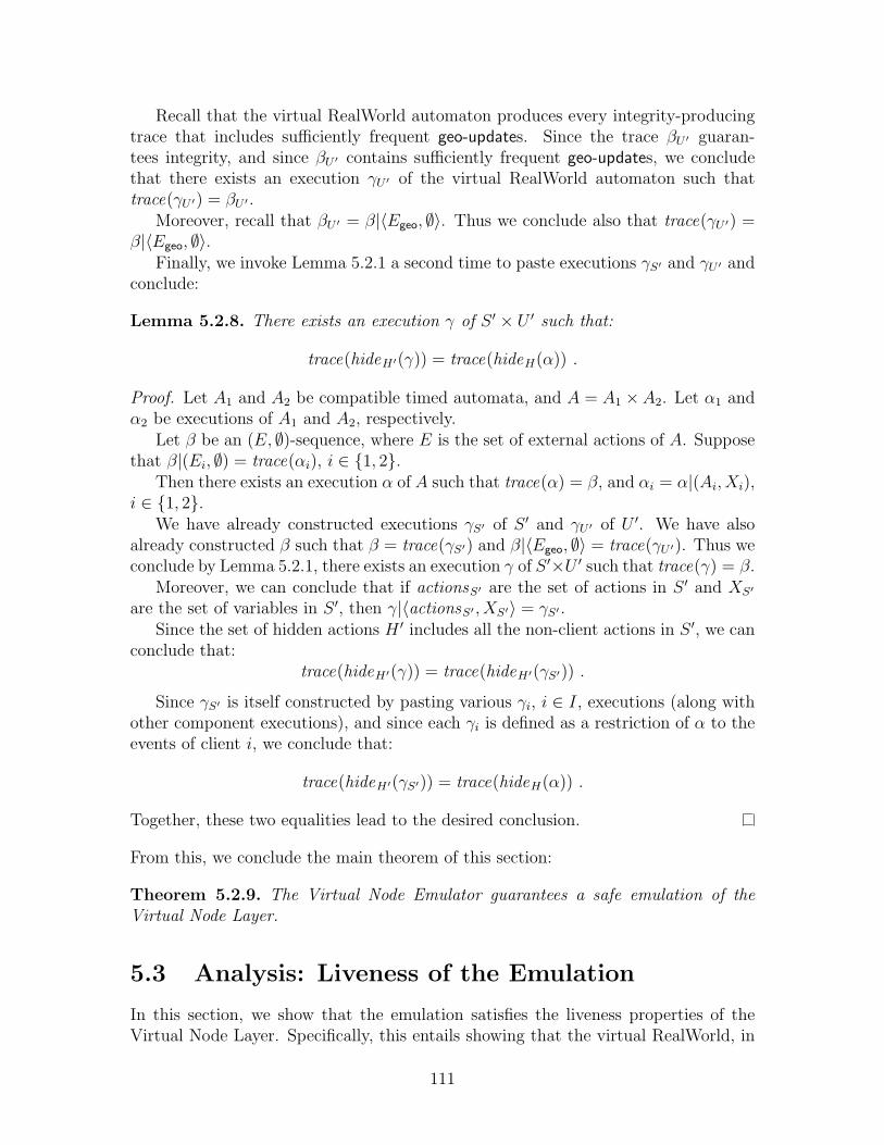
Recall that the virtual RealWorld automaton produces every integrity-producingtrace that includes sufficiently frequent geo-updates. Since the trace βU ′ guaran-tees integrity, and since βU ′ contains sufficiently frequent geo-updates, we concludethat there exists an execution γU ′ of the virtual RealWorld automaton such thattrace(γU ′) = βU ′ .
Moreover, recall that βU ′ = β|〈Egeo, ∅〉. Thus we conclude also that trace(γU ′) =β|〈Egeo, ∅〉.
Finally, we invoke Lemma 5.2.1 a second time to paste executions γS′ and γU ′ andconclude:
Lemma 5.2.8. There exists an execution γ of S ′ × U ′ such that:
trace(hideH′(γ)) = trace(hideH(α)) .
Proof. Let A1 and A2 be compatible timed automata, and A = A1 ×A2. Let α1 andα2 be executions of A1 and A2, respectively.
Let β be an (E, ∅)-sequence, where E is the set of external actions of A. Supposethat β|(Ei, ∅) = trace(αi), i ∈ {1, 2}.
Then there exists an execution α of A such that trace(α) = β, and αi = α|(Ai, Xi),i ∈ {1, 2}.
We have already constructed executions γS′ of S ′ and γU ′ of U ′. We have alsoalready constructed β such that β = trace(γS′) and β|〈Egeo, ∅〉 = trace(γU ′). Thus weconclude by Lemma 5.2.1, there exists an execution γ of S ′×U ′ such that trace(γ) = β.
Moreover, we can conclude that if actionsS′ are the set of actions in S ′ and XS′
are the set of variables in S ′, then γ|〈actionsS′ , XS′〉 = γS′ .Since the set of hidden actions H ′ includes all the non-client actions in S ′, we can
conclude that:trace(hideH′(γ)) = trace(hideH′(γS′)) .
Since γS′ is itself constructed by pasting various γi, i ∈ I, executions (along withother component executions), and since each γi is defined as a restriction of α to theevents of client i, we conclude that:
trace(hideH′(γS′)) = trace(hideH(α)) .
Together, these two equalities lead to the desired conclusion.
From this, we conclude the main theorem of this section:
Theorem 5.2.9. The Virtual Node Emulator guarantees a safe emulation of theVirtual Node Layer.
5.3 Analysis: Liveness of the Emulation
In this section, we show that the emulation satisfies the liveness properties of theVirtual Node Layer. Specifically, this entails showing that the virtual RealWorld, in
111

particular the GeoCast subcomponent, guarantees reliable and timely message deliv-ery. In order to guarantee liveness properties in the virtual infrastructure emulation,we need to make some further liveness assumptions for the underlying physical sys-tem. Specifically, we assume that:
• Any enabled action at a mobile node is executed immediately.
• For every fpcast event, the ε specified by the “Reliable Delivery” property isbounded by dfp . This implies that every message broadcast using the fpcastservice is delivered within time dfp.
• For every geocast event, the ε specified by the “Reliable Delivery” property isbounded by εgeo.
• Every message broadcast using the geocast service is delivered within time dgeo .
Also, recall from Section 3.2.3 that a focal point is said to be correct when some mobilenode arrives at least time tjoin prior to the previous mobile nodes leaving the focalpoint, and remains at least tjoin afterwards. We assume that tjoin = 4dfp + εgeo + tupd.
We also make one timing related restriction to the reset protocol. As presentedin Figure 5-6, a mobile node could choose to reset a virtual node with very fewrestrictions. In order to show that the virtual node continues to operate throughoutsome period of time, we need to assume that the virtual node is not reset unnecessarily.That is, we assume that a node only initiates a reset by performing an initiate-resetif it has remained in status = joining for time 2tfp without receiving a join response.Otherwise, without this additional restriction, a node might initiate a reset non-deterministically, even when unnecessary.
The main lemma we prove in this section is that execution γ satisfies the reliabledelivery property for the virtual GeoCast service. We also, at the same time, provethat each virtual geocast message is delivered within a bounded time.
Theorem 5.3.1. There exists some εv such that if node k ∈ I ∪ O performs avirtual-geocast(m, d)i action at time t in γ, then there exists some time t′ > t + tupd
such that if ` ∈ I ∪O and satisfies the following:
• node ` is within distance RVgeo of location d at time t′;
• node ` remains within distance RVgeo of location d until time t′ + εv; and
• node ` does not fail prior to time t′ + εv,
then a virtual-geocast-rcv(m, d)` event occurs at some point in the interval [t′, t′+ εv],delivering the message to node `. Moreover, the message is delivered within timedgeo + εv.
Proof. Notice that by assumption the ε associated with the underlying physical-layerGeoCast service is bounded by εgeo. We choose εv = εgeo + dlitfp. There are two casesdepending on whether k is a client or a virtual node. In each case we trace the virtualGeoCast from the sender to the receiver and show that it is received as required.
112

First, assume that node k is a client. In this case, by assumption, there is avirtual-geocast(m, d)k at time t, and hence we conclude that the VSE-Client for nodek performs a geocast(m, d)k at time t. Let t′ be the time specified by the reliabledelivery property of the underlying GeoCast service. If ` is a client, then the claimfollows immediately from the reliable delivery of the underlying GeoCast service.
Assume, then, that ` is a virtual node. By assumption, virtual node ` does notfail prior to some t′ + εv. From this we argue that there is some mobile node i ∈ Ithat has statusv,i = active throughout the interval [t′, t′ + εv] and does not fail priorto time t′ + εv.
This follows from the assumption that v is correct in this interval, implying thatv is populated for at least 2tjoin prior to time t′ through time t′ + εv.
We next argue that node j0, as specified by the definition of a focal point beingpopulated, as status active sufficiently prior to time t′. If any node has status active,then it is easy to see that the join protocol for j0 completes successfully, if j0 is notalready active. Otherwise, consider the case where there are no nodes with statusactive for v at time t′−2tjoin. Since v is populated from that point through time t′+εv,we can conclude that some node resets v by performing an initiate-reset during thatinterval. In particular node j0, as specified by the definition of a focal point beingpopulated, becomes active within time 4tfp: after waiting time 3fp for its join protocolto complete, it either succeeds in resetting v in the next tfp time, or it completes thejoin protocol. Thus we can assume without loss of generality that node j0 is activeat least time tjoin prior to its departure, and at least time εgeo prior to t′.
It is then easy to see (inductively) that each of the subsequent j` becomes active nolater than time εgeo prior to the previous j`−1 departing, as the previous j`−1 remainsactive and can respond to the join protocol.
Finally, since each j` remains at least tjoin after the previous j`−1 departs, there issome j` that is active and non-failed during the interval [t′, t′ + εv], as claimed. Fix ito be this mobile node.
We conclude that mobile node i receives the geocast of message m by time t′+εgeo,and immediately performs a fpcastv of message m. This arrives within time dfp , andimmediately results in a simulate-op of that operation. By the construction of γ (andLemma 5.2.6), we conclude that the virtual-geocast-rcv event occurs at exactly thatinstant, i.e., within time εv of t′. Moreover, we know that t′ occurs at most time dgeo
after time t, leading to the desired conclusion. This completes the case where k is aclient.
Next, consider the case where k is a virtual node. We first identify the geocast(m, d)associated with this virtual-geocast, and the rest follows as in the previous case. Bythe construction of execution γ, we can identify a simulate-op event that is associ-ated with the virtual-geocast(m, d)k of interest, and this event adds a message to ageocast-queue. Immediately thereafter, this message is geocast with the underlyingphysical geocast service. The remainder of this case is identical to the case where k isa client: if ` is a client, the result follows from the underlying geocast service guaran-tees; if ` is a virtual node, it follows from the fact that some mobile node replicatingthe virtual node receives the message and processes it.
113
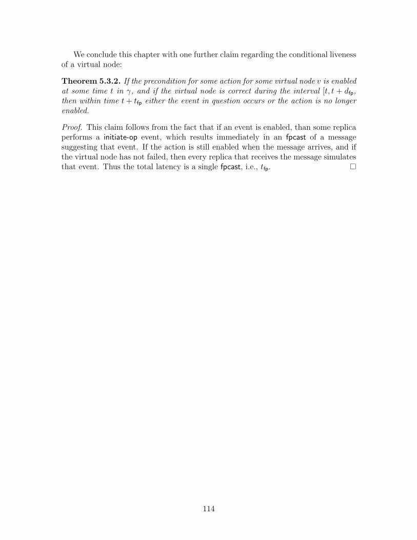
We conclude this chapter with one further claim regarding the conditional livenessof a virtual node:
Theorem 5.3.2. If the precondition for some action for some virtual node v is enabledat some time t in γ, and if the virtual node is correct during the interval [t, t + dfp,then within time t + tfp either the event in question occurs or the action is no longerenabled.
Proof. This claim follows from the fact that if an event is enabled, than some replicaperforms a initiate-op event, which results immediately in an fpcast of a messagesuggesting that event. If the action is still enabled when the message arrives, and ifthe virtual node has not failed, then every replica that receives the message simulatesthat event. Thus the total latency is a single fpcast, i.e., tfp.
114

Chapter 6
The GeoQuorums ProtocolAtomic Storage in the Virtual Object Layer
In this chapter we present the GeoQuorums Operation Manager, an algorithm forimplementing reliable, reconfigurable, atomic read/write storage in a mobile ad hocnetwork. That is, we implement a read/write shared memory that is reliable, in thesense of not failing under certain conditions, and reconfigurable, in the sense that itcan be tuned for improved performance and availability.
The GeoQuorums Operation Manager presented in this chapter serves as an ex-ample of the geoquorums approach: the problem of implementing atomic memoryis divided into two parts: (1) choosing a type of virtual infrastructure, and (2) de-veloping a protocol targeted at that specific virtual infrastructure. In this case, theGeoQuorums Operation Manager is designed to execute in the Virtual Object Layer,as described in Chapter 3.
The goal of the GeoQuorums Operation Manager is to emulate a reliable, recon-figurable, atomic read/write object with in a mobile ad hoc network. Our implemen-tation is described for a single read-write object; the composition of all the read/writeobjects results in a distributed shared read/write memory.
The GeoQuorums Operation Manager is designed for the Virtual Object Layer,which significantly simplifies the algorithm. There is no notion of mobility in theVirtual Object Layer, and as a result, the GeoQuorums Operation Manager avoidsmuch of the complexity usually associated with an ad hoc mobile network. There isno need to handle nodes joining and leaving in any special way, as the only interpro-cess communication is through the virtual objects. If at most f of the underlyingvirtual objects fail, then the Operation Manager ensures that the resulting read/writememory is robust.
The GeoQuorums Operation Manager is a quorum-based algorithm. By replicat-ing data at multiple virtual objects, and performing read and write operations onquorums of virtual objects, the GeoQuorums Operation Manager ensures that thedata is maintained reliably and consistently.
The GeoQuorums Operation Manager relies on the variable type of the virtualobjects, which we call the put/get variable type. These objects support speciallydefined operations, put, get, and two others, that allow clients to send information to
115
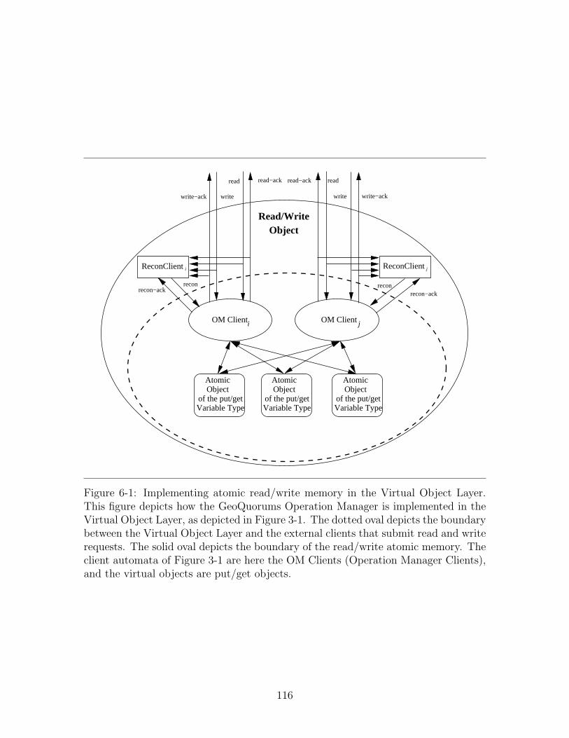
Variable Type
ObjectAtomic
of the put/getVariable Type
ObjectAtomic
of the put/getVariable Type
ObjectAtomic
of the put/get
OM Clienti OM Clientj
ObjectRead/Write
ReconClienti ReconClientj
recon−ackrecon−ack
recon
read read−ack
writewrite−ack
read−ack read
write write−ack
recon
Figure 6-1: Implementing atomic read/write memory in the Virtual Object Layer.This figure depicts how the GeoQuorums Operation Manager is implemented in theVirtual Object Layer, as depicted in Figure 3-1. The dotted oval depicts the boundarybetween the Virtual Object Layer and the external clients that submit read and writerequests. The solid oval depicts the boundary of the read/write atomic memory. Theclient automata of Figure 3-1 are here the OM Clients (Operation Manager Clients),and the virtual objects are put/get objects.
116

the objects and retrieve information from the objects, thus exchanging information.Each read and write operation uses a different port on the virtual objects, so that
earlier operations do not interfere with later ones. (In fact, an operation may use twodifferent ports for two different phases during the same operation.) This allows forimproved performance, since even if a given object is very slow during one operation(perhaps never responding, due to a lost or severely delayed message), it may be usedin a later operation.
Figure 6-1 depicts the various components of the GeoQuorums Operation Man-ager. The dashed black oval represents the boundary interface of the GeoQuorumsOperation Manager. Notice that this interface includes three operations: read, writeand recon. Our goal is to show that the GeoQuorums algorithm implements an atomicread/write object; the recon interface should be hidden from the external environmentthat will use this as a read/write object.
We assume that there exists a set of reconfiguration automata, one for each mobilenode, which we call ReconClient i, for all i in I. These reconfiguration automatagenerate recon requests, and they receive recon-ack responses. They are not a part ofthe algorithm presented in this chapter, but rather a component specified by a clientof the GeoQuorums algorithm. We place only one restriction on the ReconClientautomata: the reconfiguration clients are required to respect the environmental well-formedness requirement that a recon request is issued at node i only if there is noongoing read, write, or reconfiguration at node i. Notice that there still may beconcurrent operations at other nodes. (It would be a relatively simple modification tocompletely decouple the ReconClient automata from the read/write environment, byallowing concurrent reconfigurations and read/write operations, as is done in [38,73].We impose this restriction primarily for simplicity of presentation.)
When the GeoQuorums Operation Manager is composed with both the ReconClientautomata and the virtual objects, the recon and recon-ack actions are hidden, as arethe invoke and the respond actions on the put/get objects. This results in an exter-nal interface consisting only of read/read-ack actions and write/write-ack actions, asdepicted by the solid black oval in Figure 6-1. This matches the external signatureof a read/write object, as specified in Figure A-1.
We begin in Section 6.1 with some preliminaries, defining “configurations,” “quo-rums,” etc. We proceed in Section 6.2 to present the detailed implementation ofthe GeoQuorums Operation Manager. We prove the protocol correct in Section 6.3,and present some (conditional) performance results in Section 6.4. We discuss somefurther extensions in Section 6.5.
An extended abstract of this chapter appeared in the 17th International Sym-posium on Distributed Computing (DISC 2003) [32], and a full version appeared inDistributed Computing [33].
6.1 Preliminaries
In this section we present some preliminary definitions. (See Figure 2-1 for a summaryof notation used in Part I of this thesis.)
117

A configuration, c, consists of three components: members(c), get-quorums(c),and put-quorums(c). The set members(c) ⊆ O is a set of virtual identifiers, anddetermines which virtual objects are part of the configuration. (Recall that eachvirtual has an identifier in O.)
The sets put-quorums(c) and get-quorums(c) are collections of quorums; eachquorum is a set of virtual identifiers. Each virtual object in a quorum is a memberof the configuration. That is, each quorum is a subset of members(c).
Every get-quorum intersects every put-quorum. That is, if G ∈ get-quorums(c)and P ∈ put-quorums(c), then
G ∩ P 6= ∅ .
Moreover, if any f virtual objects fail, then at least one get-quorum and one put-quorum survive intact. That is, for any set F of f virtual object identifiers, thereexists a quorum G ∈ get-quorums(c) and P ∈ put-quorums(c) such that:
• F ∩ G = ∅
• F ∩ P = ∅.
Thus, an algorithm based on these quorums can tolerate f focal points failing. Weassume for the purpose of this chapter that the Virtual Object Layer ensures that nomore than f virtual objects fail in any execution.
We assume a fixed set of configurations that is finite, ordered, and known inadvance to all mobile nodes. Each configuration is assigned a name in M (the set ofconfiguration names).
Each configuration proposal is identified by a tuple of three components: a timewhen the configuration is proposed (according to a local clock), the node (∈ I) thatproposed the configuration, and the name of the configuration (∈ M) that is beingproposed. We refer to such a tuple (i.e., an element of C) as a configuration identifier.
As long as no mobile node proposes more than one configuration at a given instant,then every configuration identifier (i.e., every proposal) created during an executionis unique. The configuration identifiers are ordered lexicographically, based first oncomparing the time components, then comparing the process identifiers, and thencomparing the configuration names.
Practical Aspects.
We propose one set of configurations that may be particularly useful in practicalimplementations. In this case, we use two configuration c0 and c1. We take advantageof the fact that accessing nearby focal points is usually faster than accessing distantfocal points. The focal points can be grouped into clusters, using some geographictechnique [26]. Figure 6-2 illustrates the relationship among mobile nodes, focalpoints, and clusters. For configuration c0, the get-quorums are defined to be theclusters. The put-quorums consist of every set containing one focal point from eachcluster. Configuration c1 is defined in the opposite manner. Assume, for example, that
118

focal point
mobile node
cluster
Figure 6-2: Clusters of focal points, each of which represents a virtual object. Eachcluster comprises a get-quorum, while each set containing one focal point from eachcluster comprises a put-quorum.
119

read operations are more common than write operations (and most read operationsonly require one phase). If the clusters are relatively small and are well distributed (sothat every mobile node is near to every focal point in some cluster), then configurationc0 is quite efficient. On the other hand, if write operations are more common thanread operations, configuration c1 is quite efficient. Our algorithm allows the systemto switch safely between two such configurations.1
Another difficulty in implementation might be agreeing on the focal points andensuring that every mobile node has an accurate list of all the focal points and con-figurations. Some strategies have been proposed to choose focal points: for example,the mobile nodes might send a token on a random walk, to collect information ongeographic density [28]. The simplest way to ensure that a mobile node has access toa list of focal points and configurations is to depend on a centralized server, throughtransmissions from a satellite or a cell-phone tower. Alternatively, the GeoCast ser-vice itself might facilitate finding other mobile nodes, at which point the definitivelist can be discovered.
6.2 GeoQuorums Operation Manager
In this section we present the GeoQuorums Operation Manager (OM), an algorithmbuilt on the Virtual Object Layer. As the Virtual Object Layer contains two entities,virtual objects and mobile nodes, we present two specifications, one for the objects(each depicted as a “virtual object” in Figure 3-1) and one for the clients running onthe mobile nodes (each depicted as a “client” in Figure 3-1):
• put/get variable type (Figure 6-3): the variable type of the virtual objects inthe Virtual Object Layer.
• Operation Manager Client (Figure 6-4, 6-5, 6-6, and 6-7): an automaton that re-ceives read, write, and recon requests from clients and manages quorum accessesto implement these operations.
Figure 6-1 depicts the various GeoQuorums Operation Manager components. TheGeoQuorums Operation Manager (OM) is the collection of all the Operation ManagerClients (OM i, for all i in I). It is composed with the virtual objects, each of whichis an atomic object with the put/get variable type.
6.2.1 The put/get Variable Type
The put/get variable type supports four operations: put, get, confirm, and recon-done.The variable type is specified in Figure 6-3. The put and get operations are used to setand retrieve the value. We first describe the various state components of the variabletype, and then explain the different operations and how they modify the state.
1Since the original publication of the GeoQuorums protocol in [32], there has been further researchinto cluster-based quorum systems for geographic networks [18].
120
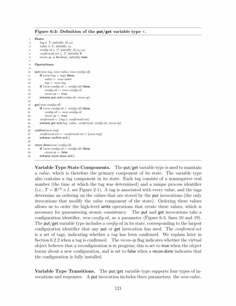
Figure 6-3: Definition of the put/get variable type τ .
1 State:2 tag ∈ T, initially 〈0, i0〉3 value ∈ V, initially v0
4 config-id ∈ C, initially 〈0, i0, c0〉5 confirmed-set ⊆ T, initially ∅6 recon-ip, a Boolean, initially false7
8 Operations:9
10 put(new-tag, new-value, new-config-id)11 if (new-tag > tag) then12 value ← new-value13 tag ← new-tag14 if (new-config-id > config-id) then15 config-id ← new-config-id16 recon-ip ← true17 return put-ack(config-id, recon-ip)18
19 get(new-config-id)20 if (new-config-id > config-id) then21 config-id ← new-config-id22 recon-ip ← true23 confirmed ← (tag ∈ confirmed-set)24 return get-ack(tag, value, confirmed, config-id, recon-ip)25
26 confirm(new-tag)27 confirmed-set ← confirmed-set ∪ {new-tag}28 return confirm-ack()29
30 recon-done(new-config-id)31 if (new-config-id = config-id) then32 recon-ip ← false33 return recon-done-ack()
Variable Type State Components. The put/get variable type is used to maintaina value, which is therefore the primary component of its state. The variable typealso contains a tag component in its state. Each tag consists of a nonnegative realnumber (the time at which the tag was determined) and a unique process identifier(i.e., T = R≥0× I, see Figure 2-1). A tag is associated with every value, and the tagsdetermine an ordering on the values that are stored by the put invocations (the onlyinvocations that modify the value component of the state). Ordering these valuesallows us to order the high-level write operations that create these values, which isnecessary for guaranteeing atomic consistency. The put and get invocations take aconfiguration identifier, new-config-id , as a parameter (Figure 6-3, lines 10 and 19).The put/get variable type includes a config-id in its state, corresponding to the largestconfiguration identifier that any put or get invocation has used. The confirmed-setis a set of tags, indicating whether a tag has been confirmed. We explain later inSection 6.2.2 when a tag is confirmed. The recon-ip flag indicates whether the virtualobject believes that a reconfiguration is in progress; this is set to true when the objectlearns about a new configuration, and is set to false when a recon-done indicates thatthe configuration is fully installed.
Variable Type Transitions. The put/get variable type supports four types of in-vocations and responses. A put invocation includes three parameters: the new-value,
121
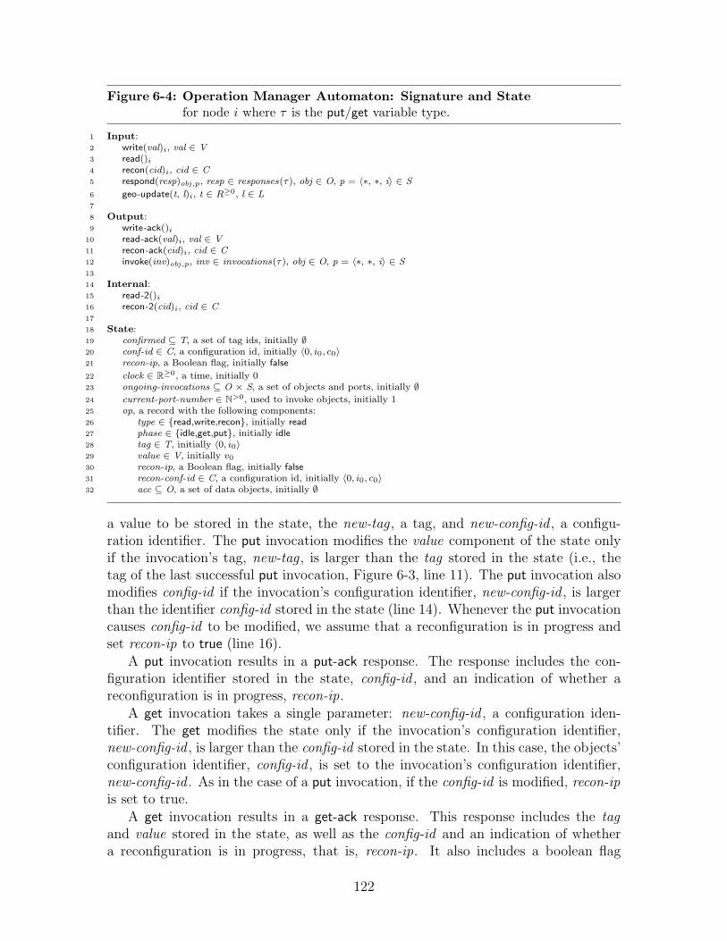
Figure 6-4: Operation Manager Automaton: Signature and Statefor node i where τ is the put/get variable type.
1 Input:2 write(val)i, val ∈ V3 read()i
4 recon(cid)i, cid ∈ C5 respond(resp)obj ,p, resp ∈ responses(τ), obj ∈ O, p = 〈∗, ∗, i〉 ∈ S
6 geo-update(t, l)i, t ∈ R≥0, l ∈ L7
8 Output:9 write-ack()i
10 read-ack(val)i, val ∈ V11 recon-ack(cid)i, cid ∈ C12 invoke(inv)obj ,p, inv ∈ invocations(τ), obj ∈ O, p = 〈∗, ∗, i〉 ∈ S13
14 Internal:15 read-2()i
16 recon-2(cid)i, cid ∈ C17
18 State:19 confirmed ⊆ T, a set of tag ids, initially ∅20 conf-id ∈ C, a configuration id, initially 〈0, i0, c0〉21 recon-ip, a Boolean flag, initially false
22 clock ∈ R≥0, a time, initially 023 ongoing-invocations ⊆ O × S, a set of objects and ports, initially ∅24 current-port-number ∈ N>0, used to invoke objects, initially 125 op, a record with the following components:26 type ∈ {read,write,recon}, initially read27 phase ∈ {idle,get,put}, initially idle28 tag ∈ T, initially 〈0, i0〉29 value ∈ V, initially v0
30 recon-ip, a Boolean flag, initially false31 recon-conf-id ∈ C, a configuration id, initially 〈0, i0, c0〉32 acc ⊆ O, a set of data objects, initially ∅
a value to be stored in the state, the new-tag , a tag, and new-config-id , a configu-ration identifier. The put invocation modifies the value component of the state onlyif the invocation’s tag, new-tag , is larger than the tag stored in the state (i.e., thetag of the last successful put invocation, Figure 6-3, line 11). The put invocation alsomodifies config-id if the invocation’s configuration identifier, new-config-id , is largerthan the identifier config-id stored in the state (line 14). Whenever the put invocationcauses config-id to be modified, we assume that a reconfiguration is in progress andset recon-ip to true (line 16).
A put invocation results in a put-ack response. The response includes the con-figuration identifier stored in the state, config-id , and an indication of whether areconfiguration is in progress, recon-ip.
A get invocation takes a single parameter: new-config-id , a configuration iden-tifier. The get modifies the state only if the invocation’s configuration identifier,new-config-id , is larger than the config-id stored in the state. In this case, the objects’configuration identifier, config-id , is set to the invocation’s configuration identifier,new-config-id . As in the case of a put invocation, if the config-id is modified, recon-ipis set to true.
A get invocation results in a get-ack response. This response includes the tagand value stored in the state, as well as the config-id and an indication of whethera reconfiguration is in progress, that is, recon-ip. It also includes a boolean flag
122

Figure 6-5: Operation Manager invoke Transitions for node i
1 Output invoke(〈get, config-id〉)obj ,p2 Precondition:3 p = 〈current-port-number, get, i〉4 〈obj, p〉 /∈ ongoing-invocations5 obj /∈ op.acc6 op.phase = get7 config-id = conf-id8 Effect:9 ongoing-invocations ← ongoing-invocations ∪ {〈obj, p〉}
10
11 Output invoke(〈put, tag, val, config-id〉)obj ,p12 Precondition:13 p = 〈current-port-number, put, i〉14 〈obj, p〉 /∈ ongoing-invocations15 obj /∈ op.acc16 op.phase = put17 tag = op.tag18 val = op.value19 config-id = conf-id20 Effect:21 ongoing-invocations ← ongoing-invocations ∪ {〈obj, p〉}22
23 Output invoke(〈confirm, tag〉)obj ,p24 Precondition:25 p = 〈k, confirm, i〉26 〈obj, p〉 /∈ ongoing-invocations27 tag ∈ confirmed28 Effect:29 ongoing-invocations ← ongoing-invocations ∪ {〈obj, p〉}30
31 Output invoke(〈recon-done, config-id〉)obj ,p32 Precondition:33 p = 〈k, recon-done, i〉34 〈obj, p〉 /∈ ongoing-invocations35 recon-ip = false36 config-id = conf-id37 Effect:38 ongoing-invocations ← ongoing-invocations ∪ {〈obj, p〉}
indicating whether the tag is confirmed. That is, it returns true if the tag is inthe confirmed-set stored in the state. Effectively, this indicates whether a confirminvocation has previously indicated that the tag is confirmed.
A confirm invocation takes one parameter: a new-tag . The confirmed-set com-ponent of the state is modified, adding the tag new-tag to this set. The confirminvocation results in a confirm-ack response.
A recon-done invocation includes a single parameter: a new-config-id , a configu-ration identifier. The recon-ip component of the state is modified if the configura-tion identifier, new-config-id , matches the config-id stored in the state. In this case,recon-ip is set to false. This indicates that the configuration associated with thatconfiguration identifier is installed, that is, that the reconfiguration that proposedthe configuration identifier is complete. This invocation results in a recon-done-ackresponse. (Note that if new-config-id is not equal to config-id , stored in the state,the invocation is ignored. While it may improve performance to allow the recon-doneaction to modify config-id , we do not do this in the interests of simplicity.)
123
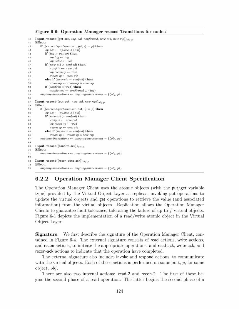
Figure 6-6: Operation Manager respond Transitions for node i
40 Input respond(〈get-ack, tag, val, confirmed, new-cid, new-rip〉)obj ,p41 Effect:42 if (〈current-port-number, get, i〉 = p) then43 op.acc ← op.acc ∪ {obj}44 if (tag > op.tag) then45 op.tag ← tag46 op.value ← val47 if (new-cid > conf-id) then48 conf-id ← new-cid49 op.recon-ip ← true50 recon-ip ← new-rip51 else if (new-cid = conf-id) then52 recon-ip ← recon-ip ∧new-rip53 if (confirm = true) then54 confirmed ← confirmed ∪ {tag}55 ongoing-invocations ← ongoing-invocations − {〈obj, p〉}56
57 Input respond(〈put-ack, new-cid, new-rip〉)obj ,p58 Effect:59 if (〈current-port-number, put, i〉 = p) then60 op.acc ← op.acc ∪ {obj}61 if (new-cid > conf-id) then62 conf-id ← new-cid63 op.recon-ip ← true64 recon-ip ← new-rip65 else if (new-cid = conf-id) then66 recon-ip ← recon-ip ∧new-rip67 ongoing-invocations ← ongoing-invocations − {〈obj, p〉}68
69 Input respond(〈confirm-ack〉)obj ,p70 Effect:71 ongoing-invocations ← ongoing-invocations − {〈obj, p〉}72
73 Input respond(〈recon-done-ack〉)obj ,p74 Effect:75 ongoing-invocations ← ongoing-invocations − {〈obj, p〉}
6.2.2 Operation Manager Client Specification
The Operation Manager Client uses the atomic objects (with the put/get variabletype) provided by the Virtual Object Layer as replicas, invoking put operations toupdate the virtual objects and get operations to retrieve the value (and associatedinformation) from the virtual objects. Replication allows the Operation ManagerClients to guarantee fault-tolerance, tolerating the failure of up to f virtual objects.Figure 6-1 depicts the implementation of a read/write atomic object in the VirtualObject Layer.
Signature. We first describe the signature of the Operation Manager Client, con-tained in Figure 6-4. The external signature consists of read actions, write actions,and recon actions, to initiate the appropriate operations, and read-ack, write-ack, andrecon-ack actions to indicate that the operation have completed.
The external signature also includes invoke and respond actions, to communicatewith the virtual objects. Each of these actions is performed on some port, p, for someobject, obj .
There are also two internal actions: read-2 and recon-2. The first of these be-gins the second phase of a read operation. The latter begins the second phase of a
124
reconfiguration operation. (We describe these operations later in this section.)
The Operation Manager Clients are composed with two sets of automata: thevirtual objects and the ReconClient automata. The invoke/respond actions allow theOperation Manager to communicate with the virtual objects. The recon and recon-ackallow the Operation Manager to communicate with the ReconClient automata.
State. The state of an Operation Manager Client consists of two parts: some generalstate that is maintained throughout the execution, and the op record, which maintainsstate specific to an ongoing operation.
The confirmed-set is a set of tags associated with operations that have completed.That is, if a tag is in confirmed-set , then some read or write operation associated withthat tag has completed.
The conf-id is the largest configuration identifier that the Operation ManagerClient has received. The Operation Manager Client receives configuration identifiersfrom respond actions for get-ack and put-ack responses.
The recon-ip flag indicates whether the Operation Manager Client believes thata reconfiguration is in progress. The Operation Manager Client sets this flag to truewhenever it receives a new, larger configuration identifier (from a respond action),and sets it to false when it receives an indication that the reconfiguration is complete(also from a respond action).
The clock is the current real time, as specified by the Geosensor component of theRealWorld.
The ongoing-operations is a set of objects and ports, indicating that an operationhas been invoked on the specified port of that object, and that a response has not yetoccurred. This is used to ensure the well-formedness condition that atomic objectsrequire: there is only one operation ongoing at any given time on a given port of agiven object.
Each invocation of a virtual objects uses a port, which consists of a sequencenumber, an operation identifier, and a node identifier. The current-port-number storesthe sequence number component of the port. An invocation by node i, then, uses theport 〈current-port-number , op, i〉, where op is either put, get, confirm, or recon-done.
Every time a new phase of an operation is begun, the current-port-number isincremented. Since only one operation can take place on a port at a time, incrementingthe port number allows the new phase to perform invocations, even if old invocationson the prior port have not completed.
The op record maintains information specific to a given operation. The op.typefield indicates the type of the ongoing operation. The op.phase field indicates thephase of the operation. (Operations may go through two phases: a get phase and aput phase; a write operation performs only a put phase.) The op.tag field indicatesthe largest tag discovered during the get phase of an operation. The op.value fieldindicates the value associated with that tag.
The op.recon-ip field indicates whether a reconfiguration is in progress. Noticethat, unlike the general recon-ip flag, the op.recon-ip flag is never reset to false untilthe phase completes. Once a reconfiguration occurs concurrently with some phase of
125

an operation (and some Operation Manager Client receives information about thisreconfiguration), the op.recon-ip flag is set to true for the rest of the phase.
The op.recon-conf-id field is used to keep track of the configuration being installedby an ongoing reconfiguration. While the reconfiguration occurs, a new reconfigura-tion may be initiated at some other mobile node. This may cause the node’s con-figuration identifier, conf-id , to be modified. The op.recon-conf-id , however, is notmodified until the ongoing reconfiguration is complete.
The op.acc set is an accumulator that maintains the set of object identifiers ofobjects that have performed a respond during the phase of an operation. A phasecompletes when op.acc contains a large enough set of object identifiers; in particular,it completes when object identifiers that are associated with appropriate quorums arecontained within the op.acc set.
Read/Write Operations. The code for read/write operations is presented in Fig-ures 6-5, 6-6, 6-7, and 6-8. We first explain how a write operation proceeds, and thengo on to explain read operations.
Each read and write operation consists of either one or two phases. A write op-eration requires only a single phase, a “put phase” that propagates the new value toat least one quorum of virtual objects. Some read operations require only a singlephase, a “get phase”, that retrieves the value from at least one quorum of virtualobjects. Other read operations require two phases: a “get phase”, that retrieves thevalue, followed by a “put phase”, that propagates the retrieved value.
Assume that the read or write operation is initiated at node i. During each phaseof the operation, node i invokes put and get operations on the virtual objects. Eachinvocation and subsequent response uses a port.
Each phase of each operation uses a unique port. When a phase begins, node ichooses a new port to use during that phase by incrementing the current-port-number(for example, Figure 6-8, line 51).
The choice of port serves two purposes. First, it ensures that the Operation Man-ager Client respects the well-formedness requirement of the virtual objects. Well-formedness requires that only one operation may occur at a time on each port of eachobject. By choosing a new port for each phase, we ensure that node i can perform in-vocations during that phase, regardless of earlier ongoing operations without violatedwell-formedness.
Second, the use of a unique port, p, for each phase allows node i to be sure that anyresponse received on port p is the result of an invocation during the phase associatedwith port p. Any response on any other port (i.e., a port that is not identified bycurrent-port-number) is ignored (see Figure 6-5, line 42, for example), since it resultsfrom an earlier (completed) phase.
A write operation begins at node i when OM i receives a write(val)i request. Nodei then examines its clock to choose a new tag for the operation (Figure 6-8, line 52).For example, if the write is initiated at time t, then the tag is chosen to be 〈t, i〉. Atthis point, the current-port-number is incremented, choosing port p for this phase ofthe operation.
126
The OM i automaton then begins a put phase, which performs put invocationson the virtual objects (Figure 6-5, lines 11–21). We allow invocations to happen,nondeterminstically, on all the virtual objects. In most cases, of course, there is noneed to contact all the virtual objects; it is simpler, however, to allow nondetermin-istic invocations and assume that an optimized implementation may impose furtherrestrictions.
The phase completes when the OM i automaton receives “sufficient” responsesfrom the objects on port p (Figure 6-5, lines 57–67). Assume that when the operationbegins, the automaton is in the configuration identified by cid = 〈∗, ∗, c〉 (i.e., cid =conf-id i). If all responses indicate that c is the most recent configuration identifier andno reconfiguration is in progress, then the operation terminates when OM i receivesat least one response from each object in some put-quorum, P ∈ put-quorums(c)(Figure 6-8, line 60).
On the other hand, if any response indicates that a reconfiguration is in progress,then OM i waits until it receives responses from objects in quorums of every configu-ration. Specifically, the phase completes when for every configuration c′ in M , thereis some quorum, P ∈ put-quorums(c′) such that every object in P has responded tonode i during the phase (Figure 6-8, line 58).
After the operation the OM i may notify objects that the tag has been confirmed,indicating that the previous operation is complete (Figure 6-5, lines 23–29). Theconfirm invocation uses the port 〈current-port-number , confirm, i〉, thus ensuring thatit does not conflict with put and get invocations.
A read request can complete in one of two ways: if the value being read has beenconfirmed, the operation completes in one phase; otherwise, the operation completesin two phases. When the OM i automaton receives a read request, it first beginsa get phase (Figure 6-7, line 4) and performs get invocations on the atomic objects(Figure 6-5, lines 1–9). Again, assume that when the operation begins, the automatonis in the configuration identified by cid = 〈∗, ∗, c〉 (i.e., cid = conf-id i).
If all responses indicate that c is the most recent configuration identifier, then theget phase terminates when OM i receives a response from each object in some quorumG ∈ get-quorums(c). Otherwise, the phase completes when for every configuration c′
in M , OM i receives a response from each object in some quorum G ∈ get-quorums(c′).At this point, OM i chooses the value associated with the largest tag from any of
the responses and determines if the operation is complete, or whether a second phaseis necessary. If the chosen tag has been confirmed, then the operation completes(Figure 6-7, lines 6–16).
Otherwise, OM i begins a second phase, a put phase. The put phase is similar tothe protocol for the write operation (Figure 6-7, lines 18–31): the current-port-numberis incremented, choosing port p for this phase of the operation; the OM i automa-ton then begins a put phase, which performs put invocations on the virtual objects(Figure 6-5, lines 11–21); the phase completes when the OM i automaton receives“sufficient” responses from the objects on port p (Figure 6-5, lines 57–67).
The knowledge of the confirmed tags is used to short-circuit the second phase ofcertain read operations. The second phase is required only when a prior operationwith the same tag has not yet completed. By notifying objects when the tag has been
127

confirmed, the algorithm allows later operations to discover that a second phase isunnecessary.
Reconfiguration. The code for the reconfiguration algorithm is presented in Fig-ure 6-5 (where Figure 6-5, lines 31–38 are used by the reconfiguration mechanism,while the rest is used also by the read/write mechanism) and Figure 6-8, lines 66–93.
The reconfiguration algorithm differs from the reconfiguration processing pre-sented in the Rambo algorithm [38, 73]. The new algorithm eliminates the Reconservice and the associated consensus service, while limiting the number of configu-rations the system can support. In Rambo, an arbitrary new configuration can beproposed, while upgrading to the new configuration requires knowledge about all ac-tive preceding configurations. The Recon service in Rambo uses consensus to agreeon the order of configurations, while the configuration-upgrade operation in Rambouses the knowledge of the order and local information about active configurations.
The new reconfiguration algorithm works with a known finite set of possible con-figurations. The algorithm does not use consensus because all possible precedingconfigurations are known. The configuration identifiers determine a total orderingon the installed configurations, however it is not necessary that a mobile node beaware of all prior configuration identifiers in the total order. It is sufficient for thereconfiguration algorithm to simply contact all configurations in order to ensure thatall configurations preceding it in the total order are contacted. Because this simplifi-cation obviates the need for a consensus service, it significantly improves efficiency.
A reconfiguration operation is a two-phase operation similar to a two-phase readoperation; it includes a get phase and a put phase. In each phase it requires contactingappropriate quorums of objects from certain configurations.
A reconfiguration begins when the Operation Manager Client receives a recon(c)input, where c names one of the configurations in M . For the sake of this discussion,assume that the recon is initiated at mobile node i.
First, the Operation Manager Client chooses a new, unique configuration iden-tifier, by examining the local clock, and using its node identifier (i.e., node i) andthe name of the new configuration (i.e., configuration c). Specifically, if the recon(c)i
occurs at time t, then the configuration identifier is cid = 〈t, i, c〉 (Figure 6-8, line 68).At the same time, node i sets its conf-id i to the new configuration identifier (〈t, i, c〉)and sets recon-ipi to true, to indicate that a reconfiguration is in progress (Figure 6-8,line 69).
The OM i then chooses a new port for the operation, incrementing the countertracking the current port number, i.e., current-port-number i (Figure 6-8, line 70).This event starts a get phase. During the get phase, several invoke(get, . . .)obj ,p eventsoccur (Figure 6-5, lines 1–9) for objects obj in quorums of all configurations in M .
When a respond(get-ack, . . .)obj ,p event occurs (on the same port p), obj is addedto op.acc. The phase completes when i has received a response from every object inat least one put-quorum and one get-quorum of each configuration in M .
At this point, a recon-2(cid)i event occurs (Figure 6-8, lines 73–82) and the Op-eration Manager Client chooses a new port, p′ (Figure 6-8, line 80). This event
128
begins the put phase. During the put phase, several invoke(put, . . .)obj ,p′ events occur(Figure 6-5, lines 11–21) for objects obj in quorums of the new configuration, c.
When a respond(put-ack, . . .)obj ,p′ event occur (on the same port p′), obj is addedto op.acc. The phase completes when node i has received responses from every objectin at least one put-quorum of the new configuration, c (Figure 6-8, line 88).
At this point, a recon-ack(cid)i event occurs (Figure 6-8, lines 84–93), ending thereconfiguration.
If conf-id i is equal to op.recon-conf-id , then recon-ipi is set to false (Figure 6-8,line 92). Otherwise, a new configuration with a larger configuration identifier hasbeen discovered by node i, and a reconfiguration for this new configuration identifiermay be in progress elsewhere. Therefore, in this case, recon-ipi is left unchanged.
When a reconfiguration is not in progress, node i may notify virtual objects thatthe reconfiguration for a certain configuration identifier is done, with recon-done in-vocations (Figure 6-5, lines 31–38).
Finally, notice that the reconfiguration algorithm proceeds in the same way, re-gardless of whether the newly proposed configuration (i.e., the configuration withname c) is the same as the old configuration: whenever the new configuration id-entifier is different from the old one, a reconfiguration occurs.
6.3 Analysis of the Operation Manager
In this section, we show that the Operation Manager guarantees atomic consistency.We show that the Operation Manager correctly implements an atomic read/writeobject by showing that a partial ordering of operations exists with the propertiesrequired by Theorem A.3.3. We first define some notation, in Section 6.3.1. We thendefine a partial order, in Section 6.3.2. Next, we prove some preliminary lemmas, inSection 6.3.3. We then outline the main part of the proof in Section 6.3.4, and thenmove on to the main body of the proof in Section 6.3.5.
6.3.1 Notation
We first define some notation that we use during the proof. Throughout this section,we fix α to be an execution of the entire system: the Operation Manager, the virtualobjects, the reconfiguration clients, and the well-formed environment, U . Addition-ally, we assume that every read and write operation in α completes. Let Π be the setof read and write operations in α.
There are two ways in which a read operation may conclude: after two phases (seeFigure 6-7, lines 33–43), or after a single phase (see Figure 6-7, lines 6–14). In thefirst case, at the end of the read operation when the read-ack occurs, op.phase = put,indicating that a “put” phase has completed. In the second case, at the end of theread operation, op.phase = get, indicating that only a single phase, a “get” phase,has completed. In this case, the tag, op.tag , is in the set confirmed immediatelybefore the read completes, so the operation completes after only the get phase.
129

Every read operation begins with a read action and ends with a read-ack action.We say that a read operation π ∈ Π that takes place at node i is a two-phase readoperation if a read-2i event occurs between the readi event and read-acki event. Op-eration π is a one-phase read operation if no read2i event occurs.
We now associate a configuration identifier with each phase of a read or writeoperation, π, based on the value of the conf-id of the operation’s initiator at the endof that phase. Specifically, if π is a one-phase read operation initiated by node i,then the “get configuration” of π, get-conf-id(π), is the value of conf-id i when π’sread-acki event occurs, ending the get phase. If π is a two-phase read operation, thenget-conf-id(π) is the value of conf-id i when operation π’s read-2i event occurs, endingthe get phase. (If π is a write operation, then π has no get phase, so get-conf-id(π)is undefined.)
If for some operation π, get-conf-id(π) = 〈t, i, c〉, then we define get-conf (π) tobe c, the name of the configuration identified by the get-conf-id(π). We say theget-conf (π) is the “get configuration” of π.
If π is a two-phase read operation (respectively, a write operation), then the “putconfiguration identifier” of π, the put-conf-id(π), is the value of the configurationidentifier conf-id i when π’s read-acki (respectively, write-acki) event occurs. If π isa reconfiguration operation, then the configuration identifier put-conf-id(π) is equalto op.conf-id i when the recon-ack event occurs. (If π is a one-phase read operation,then π has no put phase, so put-conf-id(π) is undefined.)
If for some operation π, put-conf-id(π) = 〈t, i, c〉, then we define put-conf (π) tobe c, the name of the configuration identified by the put-conf-id(π). We say theput-conf (π) is the “put configuration” of π.
Next, we associate a “recon-in-progress” flag with each phase of a read or writeoperation, based on the value of op.recon-ip at the end of that phase. Specifically, ifπ is a one-phase read operation initiated by node i, then we define get-rip(π) to bethe value of op.recon-ipi when operation π’s read-acki event occurs, ending the getphase. If π is a two-phase read operation, then get-rip(π) is the value of op.recon-ipi
when π’s read-2i event occurs, ending the get phase.If π is either a two-phase read operation or a write operation, then we define
put-rip(π) to be equal to the value of the op.recon-ipi flag when π’s read-acki orwrite-acki event occurs.
The get-rip and put-rip flags indicate whether node i detects a reconfiguration inprogress during the get or put phase of the operation. It is sufficient to consider thevalue of the op.recon-ip flag at the end of the phase, since the flag is never set to falseduring the phase: none of the invoke/respond actions set op.recon-ip to false, only thewrite, read, read-2, recon, and recon-2 event might have this effect, if recon-ip is true.If at any time during the phase recon-ip is set to true, which happens only duringa respond event, then op.recon-ip is set to true at the same time (for example, seeFigure 6-5, lines 49 and 50), and it is therefore true at the end of the phase.
During the proof, if s is a state during the execution and obj is a virtual object, weuse the terminology s .obj to refer to the state of the object. If x is a component of thestate of the object, we use the terminology s .obj .field to refer to the field componentof the object. For example, s .obj .tag refers to the tag of the object obj in state s.
130

6.3.2 Partial Order
We now construct an appropriate partial ordering, and then show that it meets thenecessary requirements of Theorem A.3.3. For a read or write operation, π ∈ Π, initi-ated at mobile node i, we define tag(π) as follows: tag(π) = op.tag i immediately afterthe acknowledgment of π occurs, that is, when the read-acki or write-acki event occurs.(In fact, the tag is often fixed earlier in the operation, as we show in Lemma 6.3.1.)For a reconfiguration operation, ρ, we define tag(ρ) = op.tag i immediately after therecon-2 event occurs. We then define the partial order ≺:
• For any two operations π1 and π2:
if tag(π1) < tag(π2) then π1 ≺ π2 .
• For any write operation π1, and any read operation π2:
if tag(π1) = tag(π2) then π1 ≺ π2 .
We show in Theorem 6.3.16 that this partial order, ≺, satisfies the three conditionsof Theorem A.3.3. The key condition to prove about the partial ordering is that it isconsistent with the ordering of operations in α. That is, we need to show Property 2of Theorem A.3.3, that if π1 and π2 are two operations, and π1 completes before π2
begins, then π2 does not precede π1 in the partial order.
6.3.3 Preliminary Lemmas
Before beginning the main part of the proof, we prove a few preliminary lemmas.First we examine when during an operation the tag of the operation is fixed. Thenwe prove some general lemmas about the propagation of tags and values during a putphase and the retrieval of tags and values during a get phase.
Recall that for operation π at node i, tag(π) is defined as the value of op.tag i
when the operation completes. In fact, if the operation has a put phase, the tag isfixed prior to the put phase of the operation.
Lemma 6.3.1. If π is a write operation at node i, then tag(π) = op.tag i immediatelyafter the writei event. If π is a two-phase read operation, then tag(π) = op.tag i
immediately after the read-2i event.
Proof. Assume π is a write operation. In this case, OM i performs only put invoca-tions. Notice that the response action, respond(put-ack, . . .)i, does not update op.tag i
Therefore op.tag i does not change after the writei event until the write-acki event thatconcludes the operation and defines the tag(π).
Assume π is a read operation. Similarly, after the read-2i event, the OM i onlyperforms put invocations, so again the tag op.tag i does not change after the read-2i
event, until the read-acki that concludes the operation and defines the tag(π).
We next note that the tag component of the virtual object’s state is nondecreasing:
131
Lemma 6.3.2. For every virtual object, obj , the tag of obj is nondecreasing. If s ands′ are two states during execution α, and s precedes s′, then s .obj .tag ≤ s ′.obj .tag.
Proof. Immediate by examination of the code that modifies tag . The tag is modifiedonly in Figure 6-3, line 13, which is executed only if new-tag > tag .
Next we consider how tag information is propagated during read and write opera-tions to virtual objects. We show that after the put phase of an operation completes,there exists a specific quorum of objects each of which has a tag no smaller than thatof the operation.
Lemma 6.3.3. Let π be a two-phase read operation, a write operation, or a recon-figuration that occurs at node i. Then there exists a put-quorum, P , in put-conf (π)such that for every object, obj , in P , tag(π) ≤ obj .tag anytime after π completes.
Proof. This lemma follows from the termination condition of the put phase of anoperation. Assume that when the put phase of π begins (i.e., immediately after thewrite, read-2, or recon-2 event), p = 〈current-port-number , put, i〉, the port numberthat is used throughout the phase. Also, assume that cid = put-conf-id(π) = 〈∗, ∗, c〉.
We divide the proof of into two subcases: the case where put-rip(π) = false, andwhere put-rip(π) = true.
First, consider the case where put-rip(π) = false. Recall that if π is a read or writeoperation, then the configuration identifier cid (which is equal to put-conf-id(π)) isequal to the configuration identified by conf-id i when the operation completes; if πis a reconfiguration, then cid is equal to the configuration identifier op.conf-id i whenthe operation completes. (Notice that our use of c is consistent with the notationused in Figure 6-8, line 56, 35, and 87.)
Then the precondition for the put phase ending is that there exists a put-quorumP ∈ put-quorums(c) such that P ⊆ op.acci (see Figure 6-8, line 60, 39, and 88.
An object obj is added to op.acc only when a respond(put-ack, . . .)obj ,p event occurs(see Figure 6-5, lines 57–67). The Virtual Object Layer guarantees that each respondevent is caused by a unique preceding invoke event, that is: invoke(put, t , v , cid)obj ,p.Since the invocation takes place on port p, this means that it must occur after thebeginning of the put phase. Therefore, the tag, t , is in fact equal to tag(π), the tagat the beginning of the put phase, by Lemma 6.3.1 and the definition of tag(π). TheVirtual Object Layer guarantees that at some point between the invocation and theresponse, the put transition was executed on the object’s state, thus ensuring thatthe tag of the object is no smaller than t.
We conclude, then, by Lemma 6.3.2, that for each object, obj ∈ P , tag(π) ≤obj .tag after operation π completes.
We now consider the case where put-rip(π) = true. Assume, then, that π is atwo-phase read operation or a write operation. In this case, the precondition forthe put phase ending is that for every configuration c′, there exists a put-quorumP ∈ put-quorums(c′) such that P ⊆ op.acci (see Figure 6-7, line 37, Figure 6-8,line 58). Fix c′ = c.
By the same argument as before, we can conclude that for every object, obj ∈ P ,tag(π) ≤ obj .tag when operation π completes.
132
When put-rip is true there is a stronger version of this lemma for read and writeoperations: there exists at least one put-quorum for each configuration where everyobject in the put-quorum has a tag no smaller than the tag of the operation.
Lemma 6.3.4. Let π be a two-phase read operation or a write operation, and assumeit occurs at node i. If put-rip(π) = true, then for every c ∈ M , there exists aput-quorum, P ∈ put-quorums(c), such that for every object, obj , in quorum P ,tag(π) ≤ obj .tag anytime after π completes.
Proof. This lemma follows from the termination condition of the put phase of anoperation. Assume that when the put phase of π begins (i.e., immediately after thewrite, read-2, or recon-2 event), p = 〈current-port-number , put, i〉, the port that isused throughout the phase. Fix any arbitrary c ∈M .
The precondition for the put phase ending is that there exists a put-quorumP ∈ put-quorums(c) such that P ⊆ op.acci (see Figure 6-7, line 37, Figure 6-8,line 58).
An object, obj is added to op.acc only when a respond(put-ack, . . .)obj ,p event oc-curs (see Figure 6-5, lines 57–67). The Virtual Object Layer guarantees that eachrespond event is caused by a unique preceding invoke event: invoke(put, t , v , c)obj ,p.Since this invocation occurs on port p, this means that it must occur after the be-ginning of the put phase. Therefore, the tag, t , is in fact equal to tag(π), the tag atthe beginning of the put phase, by Lemma 6.3.1 and the definition of tag(π). TheVirtual Object Layer guarantees that at some point between the invocation and theresponse, the put transition was executed on the object’s state, thus ensuring thatthe tag of the object is no smaller than t.
We conclude, then, by Lemma 6.3.2, that for each object, obj ∈ P , tag(π) ≤obj .tag after operation π completes. Since for every c ∈ M there exists such a put-quorum, P , the lemma holds.
We next show that a get phase effectively retrieves information on the tags froma quorum of a certain configuration.
Lemma 6.3.5. Let π be a two-phase read operation that occurs at node i. Then thereexists a get-quorum, G, in get-conf (π) such that for every object, obj in G, obj .tagwhen π begins is ≤ tag(π).
Proof. This lemma is similar to Lemma 6.3.3, and follows from the termination con-dition of the get phase of an operation.
Assume that when the get phase begins (i.e., immediately after the read event),p = 〈current-port-number , get, i〉, the port that is used throughout the phase. Also,assume that configuration identifier cid = get-conf-id(π) = 〈∗, ∗, c〉.
We divide the proof into two subcases: the case where get-rip(π) = false, andwhere get-rip(π) = true.
First, consider the case where get-rip(π) = false. Recall that cid , the get-conf-id(π),is equal to the configuration identifier conf-id i when the get phase of the operationcompletes. (Notice that our use of c is consistent with the notation used in Figure 6-7,line 20.)
133
Then the precondition for the get phase ending is that there exists a get-quorumG ∈ put-quorums(c) such that G ⊆ op.acci (see Figure 6-7, line 24).
An object, obj is added to op.acc only when a respond(get-ack, t, v, . . .)obj ,p eventoccurs (see Figure 6-5, lines 40–55). The Virtual Object Layer guarantees that eachrespond event is caused by a unique preceding invoke event: invoke(get, . . .)obj ,p.
Since the invocation takes place on port p, this means that it must occur afterthe beginning of the get phase. The Virtual Object Layer guarantees that the gettransition occurs sometime after the invocation and prior to the response. Therefore,the tag t in the response is greater than or equal to obj .tag when the invocation occurs.We therefore conclude, by observing Figure 6-5, lines 44–45, that obj .tag ≤ tag(π)when the phase begins.
We now consider the case where get-rip(π) = true. In this case, the preconditionfor the get phase ending is that for every configuration c′, and in particular for the casewhere c′ = c, there exists a get-quorum G ∈ get-quorums(c′) such that G ⊆ op.acci
(see Figure 6-7, line 22).
By the same argument as before, we can conclude that for every object, obj ∈ G,obj .tag ≤ tag(π) when the phase begins.
Again, in the case where get-rip(π) is true, we can show a stronger property: theget phase retrieves tag information from at least one get-quorum of each configuration.
Lemma 6.3.6. Let π be a two-phase read operation that occurs at node i. If recon-ipi =true at the end of the get phase, then for every configuration c ∈ M , there exists aget-quorum, G ∈ get-quorums(c) such that for every object, obj in G, obj .tag whenπ begins is ≤ tag(π).
Proof. This lemma is similar to Lemma 6.3.4, and follows from the termination con-dition of the get phase of an operation.
Assume that when the get phase of operation π begins (i.e., immediately after theread event occurs), the port p = 〈current-port-number , get, i〉, the port that is usedthroughout the phase. Fix any arbitrary c ∈M .
The precondition for the get phase ending is that there exists a get-quorum G ∈get-quorums(c) such that G ⊆ op.acci (see Figure 6-7, line 22).
An object, obj is added to op.acc only when a respond(get-ack, t, v, . . .)obj ,p eventoccurs (see Figure 6-5, lines 40–55). The focal point object model guarantees thateach respond event is caused by a unique preceding invoke event: invoke(get, . . .)obj ,p.
Since the invocation takes place on port p, this means that it must occur afterthe beginning of the get phase. The Virtual Object Layer guarantees that the gettransition occurs sometime after the invocation and prior to the response. Therefore,the tag t in the response is greater than or equal to obj .tag when the invocation occurs.We therefore conclude, by observing Figure 6-5, lines 44–45, that obj .tag ≤ tag(π)when the phase begins. Since for every c ∈M there exists such a get-quorum, G, thelemma holds.
134

6.3.4 Outline of the Operation Manager Proof
Our goal is to show that if we have two operations, π1 and π2, and π1 completesbefore π2 begins, then π2 ⊀ π1. We break this proof into a number of cases:
1. Operation π2 is a write operation (Lemma 6.3.7).
2. Operation π2 is a read operation and operation π1 is either a two-phase readoperation or a write operation.
(a) put-ip(π1) ∨ get-ip(π2) = true.Either the put phase of π1 or the get phase of π2 detects a reconfigurationin progress (Lemma 6.3.8).
(b) put-ip(π1) ∨ get-ip(π2) = false.Neither the put phase of π1 nor the get phase of π2 detect a reconfigurationin progress.
i. put-conf-id(π2) = get-conf-id(π2).The put configuration identifer of π2 is equal to the get configurationidentifer of π2 (Lemma 6.3.9).
ii. put-conf-id(π1) > get-conf-id(π2).The put configuration identifier of π1 is strictly larger than the getconfiguration identifier of π2 (Lemma 6.3.11).
iii. put-conf-id(π1) < get-conf-id(π2).The put configuration identifier of π1 is strictly smaller than the getconfiguration identifier of π2 (Lemma 6.3.12).
3. Operation π2 is a read operation and operation π1 is a one-phase read operation(Lemma 6.3.14).
6.3.5 Proving the Operation Manager Correct
We now proceed to examine the various cases, as outlined above.
Case 1: Write Operation. We first consider the case where π2 is a write operation:
Lemma 6.3.7. If π1 is a read or write operation, and π2 is a write operation, andπ1 completes before π2 begins, then π1 ≺ π2.
Proof. Assume that operation π2 occurs at node i. The result follows immediatelyby the choice of tag(π2). The tag op.tag i is chosen during the write(v)i action (seeFigure 6-8, line 52). It is chosen using the real-time clock (along with a processidentifier to break ties). The tag of π1 must have been chosen at the beginning of aprior write operation, or must be the initial value. If the tag of π1 is the initial value,then the tag of π2 is necessarily larger. Assume, then, that the tag of π1 originateswith a prior write operation.
This prior write operation must take some time strictly greater than zero to com-plete, since the write operation requires performing at least one invocation on a virtual
135
object and receiving a response from that invocation. The virtual object model guar-antees that each operation consisting of an invocation and a response on a virtualobject takes some time to complete: the invocation and the response do not occur atthe same time. Therefore the write operation must take some time strictly greaterthan zero to complete. Since π2 begins after π1 ends, it begins at some time strictlygreater than zero after the prior write operation begins.
This ensures that tag(π1) < tag(π2), which immediately implies that π1 ≺ π2, asdesired.
For the rest of the proof we assume that π2 is a read operation.
Case 2: Two-Phase Read and Write Operations. We now consider the casewhere π1 is either a two-phase read operation or a write operation, and π2 is a readoperation. We postpone until later the case where π1 is a one-phase read operation.
There are two subcases to consider, depending on whether at least one of the flagsput-rip(π1) or get-rip(π2) is true (Case 2(a)), or both flags are false (Case 2(b)).
We first consider the case where at least one of the put phase of π1 or the getphase of π2 detects a reconfiguration in progress (Case 2(a)). That is, if i initiatesoperation π1 and j initiates π2, then we assume that at least one of the following twoconditions holds:
• At the end of the put phase of π1, op.recon-ipi = true.
• At the end of the get phase of π2, op.recon-ipj = true.
Lemma 6.3.8 (Case 2(a)). Assume operation π1 is a two-phase read or write oper-ation at node i. Assume that π2 is a read operation initiated at node j, and that π1
completes before π2 begins. Assume that at least one of the following is true:
• put-rip(π1) = true, or
• get-rip(π2) = true.
Then tag(π1) ≤ tag(π2), and as a result π2 ⊀ π1.
Proof. In this case, at least one of the two nodes detects a reconfiguration in progress:node i during the put phase and/or node j during the get phase. We divide this caseinto two subcases, depending on whether it is node i or node j that detects thereconfiguration.
Subcase 1: First, assume that put-rip(π1) = true . This implies that node i detectsthe reconfiguration during the put phase of π1.
Choose c′ = get-conf (π2). Lemma 6.3.4 guarantees that there exists a put-quorum,P ∈ put-quorums(c′), such that for every object, obj ∈ P , tag(π1) ≤ obj .tag when π1
completes (since it guarantees this for every c′ ∈M).Lemma 6.3.5 guarantees that there exists a get-quorum, G, in get-quorums(c′),
the get configuration of π2, such that for every object, obj ∈ G, obj .tag ≤ tag(π2)when π2 begins.
136
Then there must exist an object, obj ∈ G ∩ P , since both are quorums of thesame configuration c′ and one is a get-quorum and the other is a put-quorum.
We already know that tag(π1) ≤ obj .tag when π1 completes. And obj .tag when π2
begins is ≤ tag(π2). Since π1 completes before π2 begins, we conclude that tag(π1) ≤tag(π2).
Subcase 2: Next, assume that get-rip(π2) = true . This implies that node j detectsthe reconfiguration during the get phase of π2.
Choose c′ = put-conf (π1). Lemma 6.3.6 guarantees that for every c′ ∈ M , thereexists a quorum, G ∈ get-quorums(c′), such that for every object, obj ∈ G, obj .tag ≤tag(π2) when π2 begins (since it guarantees this for every c′ ∈M).
Lemma 6.3.3 guarantees that there exists a put-quorum, P , in put-quorums(c′),the put configuration of π1, such that for every object, obj ∈ P , tag(π1) ≤ obj .tagwhen π1 completes.
Then there must exist an object, obj ∈ G ∩ P , since both are quorums of thesame configuration c′ and one is a get-quorum and the other is a put-quorum.
We already know that tag(π1) ≤ obj .tag when π1 completes. And obj .tag ≤tag(π2) when π2 begins. Since π1 completes before π2 begins, we conclude thattag(π1) ≤ tag(π2).
In the next case (Case 2(b)), we assume that neither the put phase of operationπ1 nor the get phase of operation π2 detects the reconfiguration in progress. Thusfor the next set of lemmas, we assume that put-rip(π1) and get-rip(π2) are both false.This case has three subcases, depending on the relationship of the put configurationidentifier of π2 and the get configuration identifier of π1. First, we assume that theseconfigurations identifiers are the same.
Lemma 6.3.9 (Case 2(b).i). Assume that operation π1 is a two-phase read operationor a write operation at node i, and that π2 is a read operation at node j. Assume thatπ1 completes before π2 begins.
Also, assume that the flags put-rip(π1) and get-rip(π2) are both false and thatthe identifier put-conf-id(π1) = get-conf-id(π2). Then we conclude that tag(π1) ≤tag(π2), and as a result, π2 ⊀ π1.
Proof. Let cid = put-conf-id(π2) = get-conf-id(π1). Assume that cid = 〈∗, ∗, c〉.Lemma 6.3.3 guarantees that there exists a put-quorum, P such that for every
object, obj ∈ P , tag(π1) ≤ obj .tag when π1 completes.
Lemma 6.3.6 guarantees that there exists a get-quorum, G ∈ get-quorums(c) suchthat for every object, obj ∈ G, the tag obj .tag ≤ tag(π2) when π2 begins.
Since P is a put-quorum and G is a get-quorum of the configuration identified byc, there must exist some object, obj ∈ P ∩G.
We already know that tag(π1) ≤ obj .tag when π1 completes. And obj .tag ≤tag(π2) when π2 begins. Since π1 completes before π2 begins, we conclude thattag(π1) ≤ tag(π2).
137
We now consider the case (Case 2(b).ii) where the put configuration identifier ofπ1 is larger than the get configuration identifier of π2. That is, we consider the casewhere put-conf-id(π1) > get-conf-id(π2). It turns out that this case cannot occur.
We first need to show that when the recon-ip flag at node i is set to false, this cor-rectly indicates that the configuration identified by conf-id is fully installed, meaningthat the reconfiguration that created conf-id has completed.
Since we assume in this case (Case 2(b).ii) that the flag get-rip(π2) is false, thislemma shows that the configuration identified by get-conf-id(π2) is fully installedprior to the start of π2.
Lemma 6.3.10. Let α′ be a prefix of α, and let c be some configuration that is notthe initial configuration:
c 6= 〈0, i0, c0〉 .
Assume that at the end of α′, conf-id i = cid = 〈∗, ∗, c〉 and recon-ipi = false. Thenfor some node j, a recon-ack(cid)j event occurs in α′.
Proof. Assume, without loss of generality, that α′ is the shortest prefix of α such thatfor any node k, conf-idk = cid and recon-ipk = false at the end of α′.
There are only two ways in which i can have configuration identifier conf-id i =cid and flag recon-ipi set to false: either i performs a recon-ack(cid)i action (seeFigure 6-8, line 92), or i receives a put-ack or get-ack response from an object spec-ifying configuration c and new-rip = false (see Figure 6-5, lines 50 and 64). (Therecon(c)i event does result in conf-id i = cid , however recon-ipi is set to true.)
Assume, however, that i receives a put-ack or get-ack from some object, obj ,specifying configuration new-cid and flag new-rip set to false. Then we know that aninvocation event, invoke(recon-done, new-cid)obj ,〈∗,j′〉, must occur prior to the put-ackor get-ack from obj , as this is the only event that can set obj .recon-ip to false.
But we assumed that i was the first node to be in this state (i.e., α′ is the shortestprefix ending with some node i in this state), so this recon-done invocation cannotoccur. Therefore i must perform a recon-ack(cid)i. The node i, then, satisfies therequired properties of node j.
We can now show that the get configuration identifier of π2 is always greater thanor equal to the put configuration identifier of π1. Therefore, the second case (Case2(b).ii) can never occur.
Lemma 6.3.11 (Case 2(b).ii). Assume operation π1 occurs in α at node i beforeoperation π2 begins at node j. Assume that π1 is a two phase read or write operation,and π2 is a read operation.
Assume that put-rip(π1) and get-rip(π2) are both false. Then put-conf-id(π1) ≤get-conf-id(π2).
Proof. If put-conf-id(π1) = 〈0, i0, c0〉 (the smallest possible value for a configurationidentifier), then clearly this result is true. Assume, therefore, that put-conf-id(π1) >〈0, i0, c0〉.
138
It is clear that recon-ipi is false at the end of the put phase of π1, since op.recon-ipi =false: whenever recon-ipi is set to true, so is op.recon-ipi, and op.recon-ip is not resetto false until the phase is completed.
Lemma 6.3.10 then implies that for some node, k, a reconfiguration acknowledg-ment, recon-ack(put-conf-id(π1))k, occurs prior to the end of the second phase of π1.In particular, the recon-ack occurs prior to the beginning of π2.
In order for the recon to complete, a recon-2 must occur. This event completesthe get phase of reconfiguration. The precondition of recon-2 requires that for everyconfiguration c′ ∈ M , there exists a quorum P ∈ put-quorums(c′) such that P ⊆op.acc. This implies that each object in quorum P responds to a get invocation inthe first phase of the recon operation. (Notice that during a reconfiguration, thereare get invocations made on objects in put-quorums. This is the one exception tothe general rule that get operations are invoked on objects in get quorums and putoperations are invoked on objects in put quorums.)
Choose c′ = get-conf (π2), and let the put-quorum P ∈ put-quorums(c′) be theput-quorum (described above) contacted by node k prior to the recon-2 event, andtherefore prior to the start of operation π2.
When the get phase of π2 completes, there exists some put-quorum of objects,G ∈ put-quorums(get-conf (π2)), such that every object, obj ∈ G has responded to aget invocation during the first phase of π2.
There must be some object obj in G ∩ P , as both G and P are quorums ofthe same configuration, get-conf (π2), and one is a get-quorum and the other is aput-quorum.
Recall that the reconfiguration is installing the configuration put-conf-id(π1). Asa result of the invocation of object obj during the get phase of the reconfiguration, itis clear that at the end of the get phase, put-conf-id(π1) ≤ obj .config-id .
As a result of the response of object obj during the get phase of π2, it is clear thatobj .config-id ≤ get-conf-id(π2) at the beginning of the get phase.
We thus conclude: put-conf-id(π1) ≤ get-conf-id(π2).
The next case to consider is when the put configuration identifier of π1 is strictlysmaller than the get configuration identifier of π2. This is the most complicated partof the proof, and relies on showing that an intervening reconfiguration operation –the one that creates configuration get-conf-id(π2) – relays information from π1 to π2.
Lemma 6.3.12 (Case 2(b).iii). Assume operation π1 is a two-phase read or writeoperation at node i. Assume that π2 is a read operation initiated at node j, and thatπ1 completes before π2 begins.
Also, assume that put-conf-id(π1) < get-conf-id(π2). Finally, assume that put-rip(π1)and get-rip(π2) both equal false. Then tag(π1) ≤ tag(π2), and as a result π2 ⊀ π1.
Proof. Some reconfiguration must occur in order to create configuration get-conf-id(π2).We first identify the reconfiguration, ρ, that creates the new configuration. We thenshow that tag(ρ) ≤ tag(π2). Finally, we show that tag(π1) ≤ tag(ρ), concluding theproof.
139

Notice that get-conf-id(π2) 6= 〈0, i0, c0〉, since it is strictly larger than put-conf-id(π1),and 〈0, i0, c0〉 is the smallest possible value for configuration identifier put-conf-id(π1).
Since op.recon-ipj = false at the end of the get phase of π2, this means thatrecon-ipj = false at the beginning of the get phase of π2: this is because no actionresets op.recon-ipj to true during an operation.
Consider the prefix α′ of α whose last event is the read event that begins π2. Thenby Lemma 6.3.10, there exists some node k that performs a recon-ack(get-conf (π2))k
in α′, that is, prior to the readj of π2. Let ρ be the recon operation concluding withthis recon-ack event.
We now show that tag(ρ) ≤ tag(π2). Lemma 6.3.3 guarantees that there existssome put-quorum, P , in the put configuration of ρ such that for each object, obj ∈ P ,tag(ρ) ≤ obj .tag at the end of the reconfiguration. Note that P is in put-quorums(c),where c is a part of the put and get configuration identifiers; that is, 〈∗, ∗, c〉 =put-conf-id(ρ) and 〈∗, ∗, c〉 = get-conf-id(π2).
Lemma 6.3.5 guarantees that there exists some get-quorum, G ∈ get-quorums(c)such that for every object, obj ∈ G, obj .tag ≤ tag(π2) when π2 begins.
Since G is a get-quorum and P is a put-quorum of the configuration identified byget-conf-id(π2), there exists an object, obj1 ∈ G ∩ P .
We have already shown that tag(ρ) ≤ obj1 .tag when ρ completes. And we havealready shown that obj1 .tag when π2 begins is ≤ tag(π2). Since ρ completes beforeπ2 begins, we conclude from Lemma 6.3.2 that tag(ρ) ≤ tag(π2).
We next show an ordering of the tags, i.e., that tag(π1) ≤ tag(ρ). Consider thefollowing reconfiguration event recon-2(get-conf-id(π2))k that occurs as part of recon-figuration ρ, ending the get phase of the reconfiguration. The precondition for therecon-2 action requires that for every configuration c′ ∈M , there exists a get-quorumsG ∈ get-quorums(c′) such that G ⊆ op.acck when the event occurs. This implies thatfor every object, obj ∈ G, an invoke(get, . . .)obj ,p event and a respond(get-ack, . . .)obj ,pevent occur during the get phase, where p is the port number during the get phaseof the reconfiguration. As part of this get operation, a perform event occurs at theautomaton for obj .
Choose c′ = put-conf-id(π1), and let quorum G be the get-quorum determined bythe end of the get phase of the reconfiguration. Lemma 6.3.3 guarantees that thereexists some put-quorum, P ∈ put-quorums(c′) such that for every object, obj ∈ P ,tag(π1) ≤ obj .tag at the end of π1.
Since G is a get-quorum of the configuration identified by c′ and P is a put-quorumof the configuration identified by c′, there exists some object, obj2 ∈ G ∩ P . Weknow that tag(π1) ≤ obj2 .tag when π1 completes, since an invocation during the putphase ensure that obj2 .tag is at least tag(π1). And we know that obj2 .tag ≤ tag(ρ)when ρ begins.
At this point, however, we do not know which event came first: the invocationduring the put phase of π1 or the response during the get phase of ρ.
Since obj2 is an atomic object, it must process these two invocations – doingperform steps in the canonical automaton – in one order or the other. Assume thatobj2 processes the invocation by ρ first, that is, the perform step in response to ρprecedes the perform step in response to π1. In this case, the response to π1 includes
140

a configuration identifier no smaller than get-conf-id(π2), the configuration beinginstalled by ρ. As a result: put-conf-id(π1) ≥ get-conf-id(π2). This contradicts ourassumption that the put configuration identifier of π1 is less than the get configurationidentifier for π2.
Therefore, we can conclude that the invocation of obj2 for π1 precedes the responseof obj2 for π2. It follows, then, that tag(π1) ≤ tag(ρ). Combining the two inequalities,we conclude that tag(π1) ≤ tag(π2), which implies that π2 ⊀ π1.
Case 3: One-Phase Read Operations. We now address the case of single-phaseread operations. We assume that π1 is a one-phase read operation, that is, it doesnot have a put phase.
Notice that in Lemma 6.3.12, we depended significantly on π1 propagating its tagto a put-quorum of objects. Since a one-phase read operation has no put phase, wecannot use this.
Instead, we rely on the fact that a one-phase read operation, π occurs only whenthe tag of operation π is confirmed, indicating that another two-phase operation, π′
has already propagated the tag of π to a put-quorum.We first need a lemma showing that if a tag, t, is confirmed, then there exists a
two-phase operation that propagated tag t to a put-quorum.
Lemma 6.3.13. Let α′ be a prefix of α, and assume that at some node i, at theend of α′, the tag t ∈ confirmed i. Then there exists an operation, π, in α′ such thattag(π) = t and π is either a two phase read-operation or a write operation.
Proof. Without loss of generality, assume that execution α′ is the shortest prefix ofα such that at the end of α′, for some node i, t ∈ confirmed i.
There are two ways in which a tag can be added to the confirmed set of i: either aresponse from some object indicates that a tag is confirmed (see Figure 6-5, line 54),or i itself completes a two-phase operation and adds t to the confirmed set (Figure 6-8,lines 43 and 64).
In the first case, this implies that there exists some object, obj , that has t ∈obj .confirmed-set at some point in α′. However, this would imply that some othernode k had performed a confirm invocation on obj (Figure 6-3, line 27) in α′, as thisis the only way in which a tag can be added to an object’s confirmed set.
This, then, implies that t ∈ confirmedk in α′, when the confirm invocation occurs.This violates the assumption that α′ is the shortest prefix to end with some node, i,containing t in confirmed i.
Therefore, node i must perform a read-acki or write-acki in α′ that adds t toconfirmed i (Figure 6-8, lines 43 and 64). The value op.tag i must be equal to t,because t is added to confirmed i. Further, if the operation is a read operation, then aprecondition of the read-acki is that op.phase = put, implying that it is a two-phaseread operation. The node i, then, satisfies all the required properties of node j.
Now we can show that with one-phase reads, the partial ordering induced by thetags is consistent with the real ordering of the operations:
141
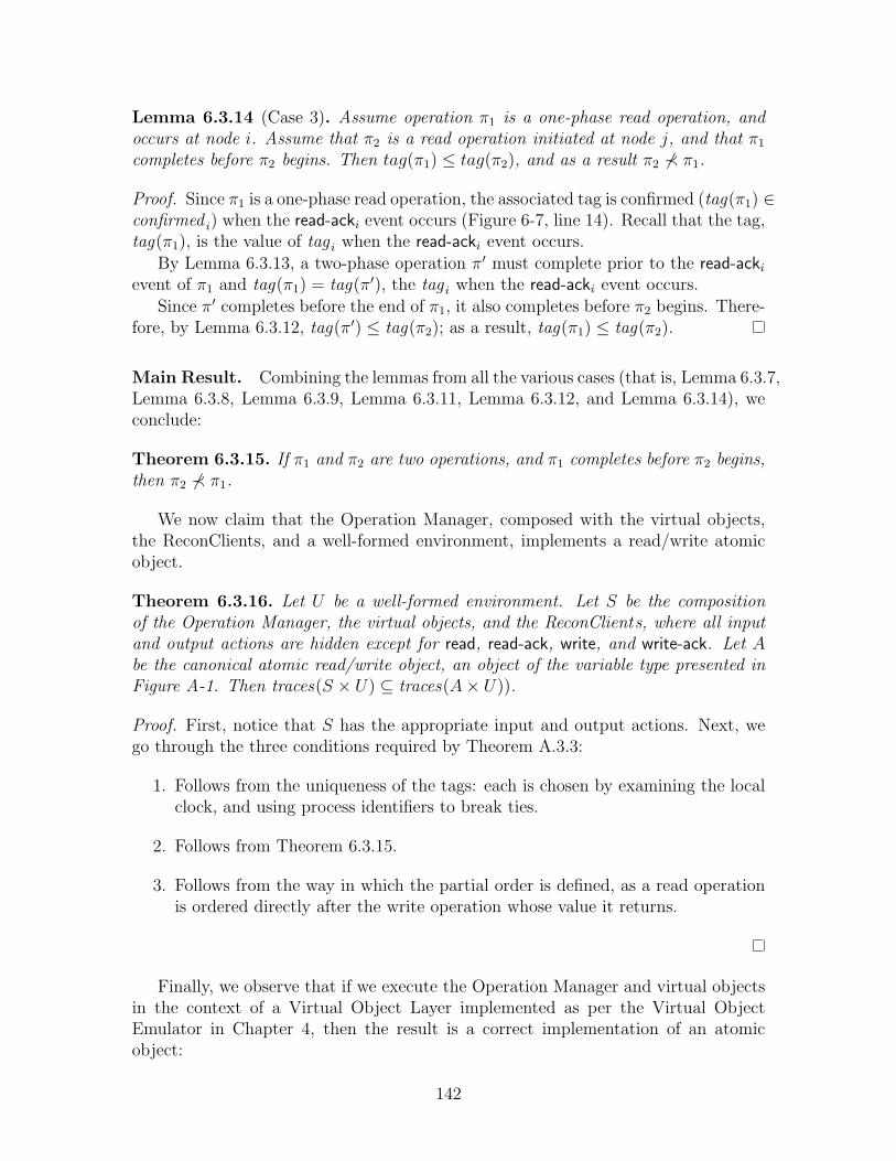
Lemma 6.3.14 (Case 3). Assume operation π1 is a one-phase read operation, andoccurs at node i. Assume that π2 is a read operation initiated at node j, and that π1
completes before π2 begins. Then tag(π1) ≤ tag(π2), and as a result π2 ⊀ π1.
Proof. Since π1 is a one-phase read operation, the associated tag is confirmed (tag(π1) ∈confirmed i) when the read-acki event occurs (Figure 6-7, line 14). Recall that the tag,tag(π1), is the value of tag i when the read-acki event occurs.
By Lemma 6.3.13, a two-phase operation π′ must complete prior to the read-acki
event of π1 and tag(π1) = tag(π′), the tag i when the read-acki event occurs.Since π′ completes before the end of π1, it also completes before π2 begins. There-
fore, by Lemma 6.3.12, tag(π′) ≤ tag(π2); as a result, tag(π1) ≤ tag(π2).
Main Result. Combining the lemmas from all the various cases (that is, Lemma 6.3.7,Lemma 6.3.8, Lemma 6.3.9, Lemma 6.3.11, Lemma 6.3.12, and Lemma 6.3.14), weconclude:
Theorem 6.3.15. If π1 and π2 are two operations, and π1 completes before π2 begins,then π2 ⊀ π1.
We now claim that the Operation Manager, composed with the virtual objects,the ReconClients, and a well-formed environment, implements a read/write atomicobject.
Theorem 6.3.16. Let U be a well-formed environment. Let S be the compositionof the Operation Manager, the virtual objects, and the ReconClients, where all inputand output actions are hidden except for read, read-ack, write, and write-ack. Let Abe the canonical atomic read/write object, an object of the variable type presented inFigure A-1. Then traces(S × U) ⊆ traces(A× U)).
Proof. First, notice that S has the appropriate input and output actions. Next, wego through the three conditions required by Theorem A.3.3:
1. Follows from the uniqueness of the tags: each is chosen by examining the localclock, and using process identifiers to break ties.
2. Follows from Theorem 6.3.15.
3. Follows from the way in which the partial order is defined, as a read operationis ordered directly after the write operation whose value it returns.
Finally, we observe that if we execute the Operation Manager and virtual objectsin the context of a Virtual Object Layer implemented as per the Virtual ObjectEmulator in Chapter 4, then the result is a correct implementation of an atomicobject:
142
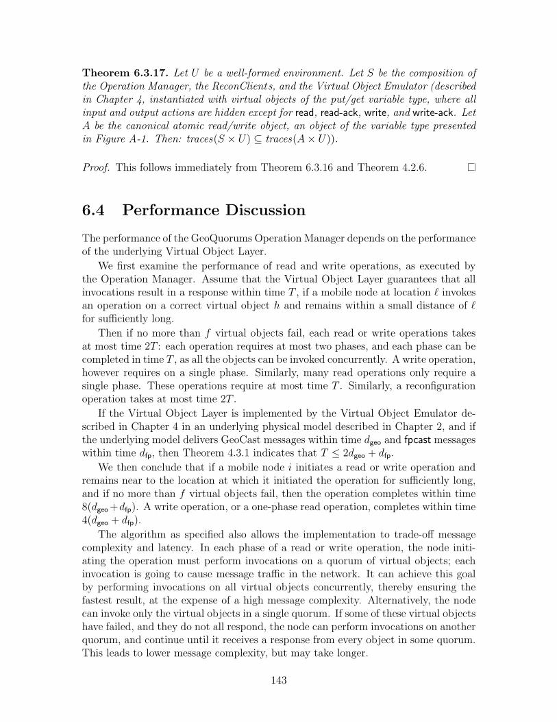
Theorem 6.3.17. Let U be a well-formed environment. Let S be the composition ofthe Operation Manager, the ReconClients, and the Virtual Object Emulator (describedin Chapter 4, instantiated with virtual objects of the put/get variable type, where allinput and output actions are hidden except for read, read-ack, write, and write-ack. LetA be the canonical atomic read/write object, an object of the variable type presentedin Figure A-1. Then: traces(S × U) ⊆ traces(A× U)).
Proof. This follows immediately from Theorem 6.3.16 and Theorem 4.2.6.
6.4 Performance Discussion
The performance of the GeoQuorums Operation Manager depends on the performanceof the underlying Virtual Object Layer.
We first examine the performance of read and write operations, as executed bythe Operation Manager. Assume that the Virtual Object Layer guarantees that allinvocations result in a response within time T , if a mobile node at location ` invokesan operation on a correct virtual object h and remains within a small distance of `for sufficiently long.
Then if no more than f virtual objects fail, each read or write operations takesat most time 2T : each operation requires at most two phases, and each phase can becompleted in time T , as all the objects can be invoked concurrently. A write operation,however requires on a single phase. Similarly, many read operations only require asingle phase. These operations require at most time T . Similarly, a reconfigurationoperation takes at most time 2T .
If the Virtual Object Layer is implemented by the Virtual Object Emulator de-scribed in Chapter 4 in an underlying physical model described in Chapter 2, and ifthe underlying model delivers GeoCast messages within time dgeo and fpcast messageswithin time dfp, then Theorem 4.3.1 indicates that T ≤ 2dgeo + dfp.
We then conclude that if a mobile node i initiates a read or write operation andremains near to the location at which it initiated the operation for sufficiently long,and if no more than f virtual objects fail, then the operation completes within time8(dgeo +dfp). A write operation, or a one-phase read operation, completes within time4(dgeo + dfp).
The algorithm as specified also allows the implementation to trade-off messagecomplexity and latency. In each phase of a read or write operation, the node initi-ating the operation must perform invocations on a quorum of virtual objects; eachinvocation is going to cause message traffic in the network. It can achieve this goalby performing invocations on all virtual objects concurrently, thereby ensuring thefastest result, at the expense of a high message complexity. Alternatively, the nodecan invoke only the virtual objects in a single quorum. If some of these virtual objectshave failed, and they do not all respond, the node can perform invocations on anotherquorum, and continue until it receives a response from every object in some quorum.This leads to lower message complexity, but may take longer.
143
6.5 Discussion
In this chapter we have presented an algorithm, the GeoQuorums Operation Manager,that implements a read/write atomic shared memory using the Virtual Object Layer.
It remains an interesting question to consider how configurations should be chosen,and when reconfiguration should occur. For example, how many configurations shouldthe algorithm use? The more configurations that are made available to the algorithm,the better the performance of read and write operations, if the correct configurationis installed. On the other hand, more configurations means slower reconfigurationand slower operations during reconfiguration.
Moreover, if there are many possible configuration, the choice of a configurationbecomes more difficult. Since there are only a finite number of configurations to choosefrom, it should be possible for the mobile nodes to determine which configurationis optimal for a given set of read and write operations. Using the techniques ofcompetitive analysis it may be possible to determine the optimal configuration for asequence of read and write operations, even without knowing the sequence in advance.
144
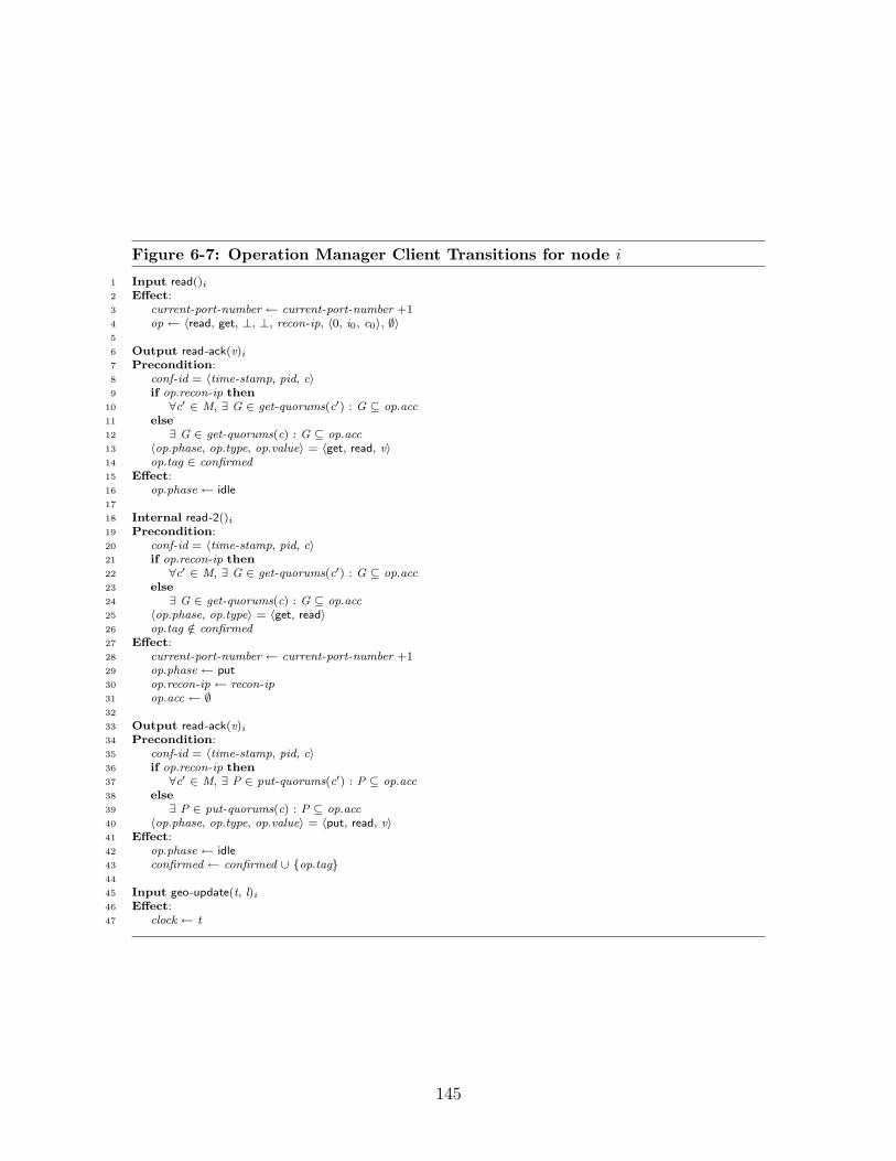
Figure 6-7: Operation Manager Client Transitions for node i
1 Input read()i
2 Effect:3 current-port-number ← current-port-number +14 op ← 〈read, get, ⊥, ⊥, recon-ip, 〈0, i0, c0〉, ∅〉5
6 Output read-ack(v)i
7 Precondition:8 conf-id = 〈time-stamp, pid, c〉9 if op.recon-ip then
10 ∀c′ ∈ M, ∃ G ∈ get-quorums(c′) : G ⊆ op.acc11 else12 ∃ G ∈ get-quorums(c) : G ⊆ op.acc13 〈op.phase, op.type, op.value〉 = 〈get, read, v〉14 op.tag ∈ confirmed15 Effect:16 op.phase ← idle17
18 Internal read-2()i
19 Precondition:20 conf-id = 〈time-stamp, pid, c〉21 if op.recon-ip then22 ∀c′ ∈ M, ∃ G ∈ get-quorums(c′) : G ⊆ op.acc23 else24 ∃ G ∈ get-quorums(c) : G ⊆ op.acc25 〈op.phase, op.type〉 = 〈get, read〉26 op.tag /∈ confirmed27 Effect:28 current-port-number ← current-port-number +129 op.phase ← put30 op.recon-ip ← recon-ip31 op.acc ← ∅32
33 Output read-ack(v)i
34 Precondition:35 conf-id = 〈time-stamp, pid, c〉36 if op.recon-ip then37 ∀c′ ∈ M, ∃ P ∈ put-quorums(c′) : P ⊆ op.acc38 else39 ∃ P ∈ put-quorums(c) : P ⊆ op.acc40 〈op.phase, op.type, op.value〉 = 〈put, read, v〉41 Effect:42 op.phase ← idle43 confirmed ← confirmed ∪ {op.tag}44
45 Input geo-update(t, l)i
46 Effect:47 clock ← t
145

Figure 6-8: Operation Manager Client Transitions for node i
49 Input write(val)i
50 Effect:51 current-port-number ← current-port-number +152 op ← 〈write, put, 〈clock, i〉, val, recon-ip, 〈0, i0, c0〉, ∅〉53
54 Output write-ack()i
55 Precondition:56 conf-id = 〈time-stamp, pid, c〉57 if op.recon-ip then58 ∀c′ ∈ M, ∃ P ∈ put-quorums(c′) : P ⊆ op.acc59 else60 ∃ P ∈ put-quorums(c) : P ⊆ op.acc61 〈op.phase, op.type〉 = 〈put, write〉62 Effect:63 op.phase ← idle64 confirmed ← confirmed ∪ {op.tag}65
66 Input recon(conf-name)i
67 Effect:68 conf-id ← 〈clock, i, conf-name〉69 recon-ip ← true70 current-port-number ← current-port-number +171 op ← 〈recon, get, ⊥, ⊥, true, conf-id, ∅〉72
73 Internal recon-2(cid)i
74 Precondition75 ∀c′ ∈ M, ∃ G ∈ get-quorums(c′) : G ⊆ op.acc76 ∀c′ ∈ M, ∃ P ∈ put-quorums(c′) : P ⊆ op.acc77 〈op.phase, op.type〉 = 〈get, recon〉78 cid = op.recon-conf-id79 Effect:80 current-port-number ← current-port-number +181 op.phase ← put82 op.acc ← ∅83
84 Output recon-ack(c)i
85 Precondition:86 cid = op.recon-conf-id87 cid = 〈time-stamp, pid, c〉88 ∃ P ∈ put-quorums(c) : P ⊆ op.acc89 〈op.phase, op.type〉 = 〈put, recon〉90 Effect:91 if (conf-id = op.recon-conf-id) then92 recon-ip ← false93 op.phase ← idle
146

Chapter 7
Virtual Infrastructure andLocal Communication
In this chapter we consider wireless networks that only have the capacity for localcommunication. That is, each mobile node can communicate only with its nearbyneighbors. By contrast, the GeoCast service introduced in Chapter 2 allowed formobile nodes to send messages across the network to other devices that may be faraway. The fpcast service, though in many ways “local,” also guarantees more thanyour typical wireless MAC layers. Thus, in this chapter we assume only a simple localbroadcast service that allows nearby nodes to communicate reliably.
The goal of this chapter is to provide a brief overview of how to modify theabstractions and protocols described in the previous sections for a wireless networkequipped only with a simple local broadcast service. We begin in Section 7.1 bydescribing the behavior of the local broadcast service. (The other attributes of thephysical model remain unchanged.) Next, in Section 7.2, we briefly describe a virtualinfrastructure model that includes only local communication. In Section 7.3, wedescribe how to implement the fpcast service (described in Chapter 2) using the simplelocal broadcast service. Finally, in Section 7.4, we describe the few modifications tothe emulator algorithm from Chapter 5 needed to implement the local-only virtualinfrastructure model described in this chapter.
There are two reasons to focus on local communication. First, it is a more realisticmodel for wireless networks. Most wireless communication is local in nature, and thusit makes sense to focus on what can be accomplished using only local communication.Second, a local virtual node layer may enable the construction of many interestingnon-local communication mechanisms. For example, we can build long-distance Geo-Cast protocols on top of a local virtual node layer; these GeoCast protocols may haveadvantages (in terms of simplicity and reliability, say) over GeoCast protocols builtdirectly on a mobile ad hoc network.
147

7.1 Local Broadcast
We begin by considering a modification of the physical model presented in Chapter 2:instead of a GeoCast service and several fpcast services, we assume only a “localbroadcast” service. All other aspects of the model remain unchanged. Formally, thelbcast service is part of the RealWorld automaton; we describe it here in terms of itssafety and liveness properties.
The local broadcast service lbcast is parameterized by two values: a radius, Rlb
and a message delay dlb. When some node i performs a lbcast(m)i, the lbcast servicedelivers the message—via a lbcast-rcv(m)j—to every mobile node j within a radiusRlb of the sender; every message is delivered within dlb time. Formally, the servicehas the following properties:
Reliable Delivery : Assume that the mobile node i performs a lbcast(m)i in location` at time t. Then for every mobile node j that is within distance Rlb of location` at time t and remains non-failed within distance Rlb of location ` until timet + dlb , a lbcast-rcv(m)j event occurs by time t + dlb , delivering the message tonode j.
Integrity : For any message m and mobile node i, if a lbcast-rcv(m)i event occurs,then a lbcast(m)j event precedes it, for some mobile node j.
Latency Lower Bound : Each message takes some time > tupd to be delivered.
Intuitively, sending a message using this service should be thought of as makinga single wireless broadcast (with a small number of retries, if necessary, to avoidcollisions). For small Rlb, this service is a reasonable (if simplistic) model of sendingand receiving messages using wireless broadcast.
7.2 Local Virtual Node Layer
We next introduce a virtual infrastructure abstraction that contains only local com-munication. As in the Virtual Node Layer described in Chapter 3, we consider anabstraction consisting of clients and virtual nodes. Each client is associated with amobile node in I; each virtual node is associated with a focal point in O.
The clients and virtual nodes communicate with each using a virtual lbcast service.Unlike the Virtual Node Model presented in Chapter 3 in which clients and virtualnodes could send messages to each other via geocast, in this case, all communicationis local. If a client or a virtual node performs an virtual-lbcast, only nearby clientsand virtual nodes receive the message.
For the purpose of this revised virtual node model, we define the focal pointsmore specifically. Each focal point is defined in terms of its focal point center—whichmay move through the network. The focal point region is defined as a circle of somefixed radius around the focal point center. Recall that Rlb is the radius of the localbroadcast service, vmax is the maximum velocity of a mobile node, and vfp-max is themaximum velocity of a focal point. Formally, if, at time t, the focal point center is at
148

fp-center(t)h, we define fp-region(t)h as a circle of radius Rlb/2−tupd(vmax+vfp-max). Asin Chapter 2, the additional buffer zone inside the circle defined by the local broadcastservice ensures that nodes can communicate using the lbcast service as long as theybelieve they are in a focal point.
7.3 The Focal Point Broadcast Service
A key building block for the protocols presented in Chapters 4 and 5 is the fpcastservice which guarantees reliable delivery of messages in some fixed total order tomobile nodes in a focal point. Since most real networks are not by default equippedwith such a service, we have describe a local broadcast service lbcast that captures ina simplified manner the behavior of a reliable wireless MAC layer.
In this section, we show how to implement the fpcast service in networks thatprovide only a local broadcast service using a standard ordering technique originallysuggested by Lamport [58]. We fix one focal point h ∈ O for the remainder of thissection, and discuss the implementation of fpcasth.
For the purpose of this section, we assume that tupd is arbitrarily small, i.e., thateach mobile node has access to precisely real time at any instant. Formally, thisis equivalent to restricting our attention to executions in which a geo-update eventoccurs immediately prior to every other event. It is relatively straightforward toextend the claims in this section to tolerate slight inaccuracies in the time.
We now proceed to describe the protocol. Pseudocode for the fpcast protocol canbe found in Figure 7-1.
Implementing fpcast. The lbcast service already guarantees integrity and reliabledelivery. The key property that needs to be enforced is the total ordering property.This ordering is enforced through the use of timestamps.
Recall that each mobile node receives frequent updates via geo-update events ofthe most recent time. Each message is tagged with the time when it is sent. Messagesare delivered in order (with ties broken arbitrarily and deterministically, see Figure 7-1, lines 41–43) at time dlb after the time at which they are tagged (see Figure 7-1,line 40). If a mobile node ever moves too far away from the focal point center, i.e., if itever exits the focal point, then all waiting messages that have not yet been deliveredare dropped (see Figure 7-1, lines 60–61). If a node ever receives a messages that istoo old, i.e., its timestamp is earlier than t−dlb, where t is the current time accordingto the receiving node, then the message is discarded (see Figure 7-1, lines 24–26).(Notice that a message may be delivered late, despite the reliable delivery deadline,if, say, the sending node is farther than distance Rlb away, for example.) If a node wasnot in the focal point when a message was sent, it is discarded (Figure 7-1, line 25).
It follows immediately that the fpcast service guarantees integrity:
Lemma 7.3.1. fpcasth satisfies the integrity property.
Proof. A message m is delivered only if it is received from the lbcast service, and bythe integrity of the lbcast service we can conclude that m was previously broadcast
149
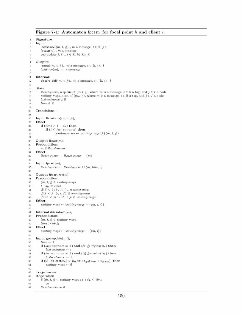
Figure 7-1: Automaton fpcasth for focal point h and client i.
1 Signature:2 Input:3 lbcast-rcv(〈m, t, j〉)i, m a message, t ∈ R, j ∈ I4 fpcast(m)i, m a message5 geo-update(t, `)i, t ∈ R, `∈ R× R6
7 Output:8 lbcast(〈m, t, j〉)i, m a message, t ∈ R, j ∈ I9 fcast-rcv(m)i, m a message
10
11 Internal:12 discard-old(〈m, t, j〉)i, m a message, t ∈ R, j ∈ I13
14 State:15 lbcast-queue, a queue of 〈m, t, j〉, where m is a message, t ∈ R a tag, and j ∈ I a node16 waiting-msgs, a set of 〈m, t, j〉, where m is a message, t ∈ R a tag, and j ∈ I a node17 last-entrance ∈ R18 time ∈ R19
20 Transitions:21
22 Input lbcast-rcv(〈m, t, j〉)i
23 Effect:24 if (time ≥ t − dlb) then25 if (t ≤ last-entrance) then26 waiting-msgs ← waiting-msgs ∪ {〈m, t, j〉}27
28 Output lbcast(m)i
29 Precondition:30 m ∈ lbcast-queue31 Effect:32 lbcast-queue ← lbcast-queue − {m}33
34 Input fpcast(m)i
35 lbcast-queue ← lbcast-queue ∪ 〈m, time, i〉36
37 Output fpcast-rcv(m)i
38 Precondition:39 〈m, t, j〉 ∈ waiting-msgs40 t +dlb = time41 6 ∃ t′ < t : 〈·, t′, ·〉∈ waiting-msgs42 6 ∃ j′ < j : 〈·, t, j′〉 ∈ waiting-msgs43 6 ∃ m′ < m : 〈m′, t, j〉 ∈ waiting-msgs44 Effect:45 waiting-msgs ← waiting-msgs − {〈m, t, j〉}46
47 Internal discard-old(m)i
48 Precondition:49 〈m, t, j〉 ∈ waiting-msgs50 time > t+dlb
51 Effect:52 waiting-msgs ← waiting-msgs − {〈m, t〉}53
54 Input geo-update(t, `)i
55 time ← t56 if (last-entrance = ⊥) and (`∈ fp-region(t)h) then57 last-entrance ← t58 if (last-entrance 6= ⊥) and (`/∈ fp-region(t)h) then59 last-entrance ← ⊥60 if (|`− fp-centerh| > Rlb/2 +tupd(vmax +vfp-max)) then61 waiting-msgs ← ∅62
63 Trajectories:64 stops when65 ∃ 〈m, t, j〉 ∈ waiting-msgs : t +dlb ≤ time66 or67 lbcast-queue 6= ∅
150

by some node i.
It is also easy to see that messages are delivered in the same order at all mobilenodes. Specifically, they are delivered in the order specified by their time stamps:
Lemma 7.3.2. fpcasth satisfies the total order property.
Proof. Consider two messages mr and ms tagged with (and sent at) times tr and tsrespectively. Assume without loss of generality that tr ≤ ts, and that some node idelivers both messages mr and ms. Then we argue that i delivers mr prior to ms.Specifically, notice that i delivers message ms at time ts + dlb, by the rule on wheni delivers messages. Moreover, i delivers mr only if mr is received no later thantime tr + dlb; otherwise, mr is discarded by the rule discarding late messages. Sincetr ≤ ts, we conclude that i receives mr prior to delivering ms. Thus, because i deliversmessages in order according to timestamps, we conclude that i delivers mr prior todelivering ms.
Next, we argue that fpcasth guarantees reliable delivery. In particular, we arguethat within time dlb after a message m is broadcast, every nearby node receives it:
Lemma 7.3.3. fpcasth satisfies the reliable delivery property.
Proof. Assume that for some mobile node i and some message m, a fpcast(m)h,i eventoccurs at time t, and that i is in focal point h at time t. Moreover, assume that nodej is also in focal point h at time t and remains in focal point h and non-failed throughtime t + dlb. We need to show that j delivers message m by time t + dlb.
First, notice that i re-broadcasts the message m with the lbcast service immedi-ately at time t, and t is thus the tag associated with message m in the local broadcast.Since focal point h has diameter ≤ Rlb/2, and since i is in focal point h when thelbcast occurs, and since j is in the focal point through time t + dlb, we conclude fromthe reliable delivery property of the lbcast service that by time t + dlb node j receivesthe message m via a lbcast-rcvj. Since j has remained in the focal point from the timeat which m was broadcast through time t + dlb, we conclude that last-entrance i ≤ t.Thus message m is added to waiting-msgs and delivered.
Next, we argue that fpcasth satisfies the consistent delivery property. Specifically,we show that if some non-failed mobile node i receives messages m1 and m3 and doesnot leave the focal point between receiving messages m1 and m3, and if there is somemessages m2 : m1 < m2 < m3 according to the order induced by the tags, then thatmobile node receives messages m2.
Lemma 7.3.4. fpcasth satisfies the consistent delivery property.
Proof. Let m1, m2, and m3 be three messages such that a fpcast(mr) occurs for eachr ∈ {1, 2, 3}. Moreover, assume that the total ordering property induces an orderm1 < m2 < m3 on these messages. Recall (as was shown in the proof of Lemma 7.3.2)that this order is induced by the tags t1, t2, t3, respectively, tags associated with eachmessage when it is rebroadcast using the lbcast survice.
151
Assume that some node i delivers messages m1 and m3, and that node i does notexit the focal point region for h from the point at which i receives m1 through thepoint at which i receives m3. We show that i receives message m2.
First, we argue that i is in the focal point when m2 is sent. There are three casesdepending on when m2 is sent with respect to when m1 is first received by i, andwhen m1 is delivered. Consider the case where m2 is broadcast prior to m1 first beingreceived by i: then we know that last-entrance i < t, and hence i last entered thefocal point prior to m1 and m2 being broadcast. Next, consider the case where m2 isbroadcast after m1 is received by i but before m1 is delivered by i: we know that idoes not exit the focal point during this interval, since it discards all the waiting-msgswhen it exits the focal point. Finally, consider the case where m2 is broadcast after m1
is delivered by i: then by assumption i remains in the focal point until m3 is delivered;since t1 ≤ t2 ≤ t3, we know that m2 is broadcast prior to m3 being delivered.
Next, notice that i remains in the focal point through time t2 + dlb, i.e., longenough for m2 to be delivered. Specifically, we know that i does not exit the focalpoint prior to t3 + dlb, or m3 would be discarded, and t2 ≤ t3. We therefore concludethat by the reliable delivery property of the fpcast service in Lemma 7.3.3, messagem3 is delivered.
7.4 Remaining Implementation Details
In this section we discuss the remaining changes that need to be made to the VirtualNode Emulator described in Chapter 5 in order to emulate the Local Virtual NodeLayer. We have already shown in Section 7.3 how to implement the fpcast service.The Virtual Node Emulator also makes use of a geocast service—which is not availablein the revised model.
Notice, however, that the emulator only uses the geocast service to forward mes-sages from the VNE-Client automata to the VNE-Server automata. Instead, we usethe lbcast service to transmit messages between these components of the emulator.As a result, a message broadcast by a client (in the abstraction) is only received bya VNE-Server in the emulation if the client is near to the focal point.
This, however, satisfies exactly the local communication property desired of therevised virtual infrastructure abstraction. The analysis of the resulting protocol isexactly identical to that described in Chapter 5, with the only modification being therevised “reliable delivery” argument: the emulator ensures reliable delivery since if aclient is close to a focal point, then its message reaches a gen-server and the argumentproceeds as before.
152

Part II
Virtual Infrastructure:Collision-Prone Networks
153

154

Introduction
There are several challenges associated with developing algorithms for ad hoc net-works. In the first part of this thesis, we proposed the idea of virtual infrastructureto address the difficulties arising from unreliable devices and unpredictability. In thissecond part of the thesis, we address the problem of unreliable communication. Webegin in Chapter 8 by introducing a new model for wireless networks that includesunreliable communication, as well as node failures and mobility. We then define anew type of virtual infrastructure in Chapter 9. Next, we present an algorithm thatimplements this form of virtual infrastructure (Chapter 10), and prove that the al-gorithm is correct (Chapter 11). The possibility of lost messages introduces severaldifficulties, and leads to a much more involved emulation algorithm1.
Overview
It is an unfortunate fact that communication in wireless networks is unreliable: col-lisions and other wireless interference cause significant message disruption in realdeployments of ad hoc wireless networks. Several recent experimental studies [37,52,105, 108] suggest that even with sophisticated collision avoidance mechanisms (e.g.,802.11 [1], B-MAC [86], S-MAC [107], and T-MAC [101]), and even under low trafficloads, the fraction of messages being lost can be as high as 20− 50%.
By contrast, the virtual infrastructure algorithms presented in Part I of this thesisdepend significantly on reliable communication. Recall that in order to implement avirtual node (or even a virtual object), the state of the virtual node is replicated ata set of mobile nodes, and the mobile nodes run a replicated-state-machine protocolin order to maintain a consistent replicated state. The main protocol depends onthe reliable dissemination of messages in order to ensure that each replica receivesthe same set of messages. Moreover, the replicated-state-machine protocol in Part Idepends on an even stronger property: it assumes that messages are delivered toeach mobile node in the same order; alternatively (as is discussed in Chapter 7),it assumes that messages are delivered in a timely fashion. Real wireless networksprovide neither of these guarantees.
Thus we conclude that, while the idea of virtual infrastructure, as proposed inPart I, may be effective at coping with unreliable mobile devices and unpredictable
1Notice that although the emulation algorithm itself is quite involved, the abstraction presentedto the developer building applications atop the virtual node layer remains relatively simple, muchas in Part I of this thesis.
155
patterns of mobility, the actual implementations of virtual infrastructure presentedin Part I are not directly suitable for deployment in real wireless ad hoc networks.The primary goal of Part II is to design and implement a virtual infrastructure thatcan tolerate unreliable communication, and thus is more suitable for real wirelessnetworks. We now proceed to present an overview of Part II.
The Basic Model for Wireless Ad Hoc Networks
We begin Part II by introducing (in Chapter 8) a new model for wireless ad hoc net-works that allows for unreliable communication. As in Part I, the network consists ofa set of mobile nodes moving arbitrarily in the two-dimensional plane. The key differ-ence from Part I, however, is that the mobile nodes communicate via a synchronous,unreliable communication service. That is, each mobile node broadcasts and receivesmessages in a synchronous, round-based fashion, and messages may be lost.2 Eachmobile node is modelled by a timed I/O automaton.
To cope with unpredictable message loss, we augment the system with receiver-centric collision detectors. Intuitively, collision detectors attempt to notify a mobilenode when a message that it should have received was lost. Notice that a collisiondetector does not provide any information to the original transmitter as to whetherits messages were received. Intuitively, a collision detector monitors the broadcastmedium and attempts to deliver notifications when messages are lost; a simple im-plementation of a collision detector might be based on “carrier sensing,” a techniquethat raises a warning whenever a certain signal threshold is reached. Collision detec-tors provide no information on the number of lost messages or the identities of thenodes that send the messages. Moreover, there is no guarantee that a node perform-ing a transmission can detect collisions. A collision detector answers only the binaryquestion of whether there appears to have been at least one message lost.
Moreover, we consider collision detectors that are themselves unreliable, as firstintroduced in [23, 79]. There are two types of unreliable behavior: false negatives, inwhich the collision detector fails to detect a collision, and false positives, when thecollision detector reports a collision inaccurately. In practice, we believe it possible todetect collisions correctly most of the time. In Part II, we focus primarily on faultycollision detectors that detect occasional false positives, but eventually stabilize andbecome reliable3.
To this point, we have made no assumptions on the reliability of message delivery.In order for an algorithm to achieve progress, however, eventually some messages mustbe delivered. In wireless networks that share a single channel of of the electromagneticspectrum, messages can be delivered when there is no interference on the channel.
2Notice that it is possible to view the communication service in Part I as, essentially, synchronous:the suggested implementation for the the fpcast service relies on a timely communication service,which is effectively equivalent to a synchronous system.
3As elsewhere in this thesis, when we consider a stabilization point after which the collisiondetectors become reliable, in practice we simply require the collision detectors to behave correctlyfor sufficiently long, i.e., long enough for our protocols to make progress.
156

That is, if only one node in a region broadcasts, there is the possibility that itsmessage is delivered. We assume that, eventually , if the broadcast contention is lowenough in a given round, then there are no collisions and the message is delivered toevery nearby mobile node. We refer to this property as “eventual collision freedom.”Since the property holds only in an eventual sense, however, and since the nodes areunaware of when the network stabilizes, a transmitting node can never be certainthat its messages are received.
Finally, we assume that the nodes have access to a set of contention managerswhich provide advice on when a node should broadcast and when a node should besilent, leaving the channel free for its neighbors to broadcast. Again, the contentionmanagers are unreliable: they often give bad advice, and there is no guarantee that atransmitting node that is advised to broadcast will succeed in avoiding interference.We assume, however, that eventually the contention managers stabilize and providegood advice.
The Virtual Infrastructure System
In Chapter 9 we present the virtual infrastructure system. Much like the virtualinfrastructure described in Part I, the abstraction consists of virtual nodes, residingat fixed points in the network, and clients, that move arbitrarily. The clients andvirtual nodes communicate using a broadcast service much like that available to theunderlying mobile nodes: communication is unreliable, and the broadcast serviceguarantees eventual collision freedom. Each virtual node and each client receivesfeedback from a collision detector as to when messages are lost, and advice from acontention manager as to when to broadcast and when to be silent. In general, thevirtual infrastructure system strongly resembles the underlying network model, withthe main difference being the existence of additional virtual nodes that are morereliable and predictable than the underlying mobile nodes. The additional robustnessof the virtual nodes, in contrast to the unreliable mobile nodes, provides significantbenefit to developers attempting to build application atop a virtual infrastructurelayer.
The Emulator Algorithm
In Chapter 10 we present an algorithm to emulate the virtual infrastructure in the un-derlying network model. The algorithms itself is quite involved, and we introduce it ina series of steps. The chapter begins with an overview of the algorithm (Section 10.1),and then proceeds to present the algorithm formally and in more detail (Section 10.2).The chapter concludes with an argument that the resulting automata are well-formed,satisfying the appropriate requirements of the basic model (Section 10.3).
As in Part I, each virtual node is emulated by a set of replicas that happen tobe near to the virtual node’s designated location. This replication guarantees faulttolerance: as mobile nodes enter the virtual node’s region, they join the emulation;as mobile nodes leave the virtual node’s region, they leave the emulation.
157

As in Part I, the key difficulty in implementing virtual infrastructure is maintain-ing the consistency of the replicas. Unlike in Part I, however, we cannot assume thatthe broadcast service is reliable (or that it guarantees totally-ordered message deliv-ery), and hence a more involved scheme is needed to maintain the replica consistency.
In order to maintain consistency, the replicas participate in repeated instancesof an “agreement protocol”: each instance of the agreement protocol represents one(virtual) round of the virtual infrastructure emulation. The goal of each instance is forthe replicas to agree on a specific execution for the virtual node up to and includingthe (virtual) round associated with that instance. When the agreement protocolcompletes successfully, all the replicas share the same virtual node execution, andhence share the same virtual node state.
Each instance of the agreement protocol takes a fixed number of (basic) rounds.When the network is “unstable,” agreement may not be reached within the alottednumber of rounds: lost messages, false positives from a collision detector, or badcontention management advice can result in a failed agreement instance. In thiscase, the decision as to the appropriate behavior for the associated (virtual) round ispostponed, and the next agreement instance is begun. Eventually, once the networkhas stabilized, the agreement instances complete successfully, and the entire executionup to the current virtual round—including all previously undetermined rounds—isdetermined.
Each replica needs to distinguish (virtual) rounds in which the agreement instancehas completed successfully, and (virtual) rounds in which the agreement instancehas failed. To this end, the agreement protocol is similar, in ways, to “three-phasecommit” protocols (see, e.g., [95,96]): each replica determines a color for each round—green, yellow, orange, or red—which determines the level of success for that instanceof agreement. At any two replicas, the color differs by at most one shade. Thus,if a replica determines that a (virtual) round is green, it can safely conclude thatthe agreement instance was successful, as no replica designated the round as red.Similarly, if a replica determines that a (virtual) round is red, it can safely concludethat the agreement instance failed.
The resulting iterated agreement protocol ensures that at the end of each (virtual)round, all the replicas behave in a consistent manner, and that eventually, when thenetwork stabilizes, the virtual node simulated by the replicas successfully broadcastsand receives messages without inducing collisions.
Proof of Correctness
In Chapter 11 we prove that the protocol presented in Chapter 10, when executed inthe basic model described in Chapter 8, implements the virtual infrastructure systempresented in Chapter 9.
The proof consists of two main parts. In the first part of the proof (Sections 11.2–11.8), we prove a series of properties about the round colors, and the associated statesof all the replicas. We show that the color of a round at two replicas differs by at mostone shade (Lemma 11.5.9 and Corollary 11.5.7), and that after a “good” round, allthe replicas agree on the state of the virtual node (Lemma 11.7.11). Finally, we show
158

that eventually, when the network is stable, all the rounds are good (Lemma 11.8.12).In the second part of the proof (Sections 11.9–11.15), we explicitly construct the
execution of the virtual infrastructure that is emulated by a given execution of theemulator protocol. We construct each of the component executions separately, defin-ing an execution for each virtual node (Section 11.9), for each client and contentionmanager (Section 11.10), for the collision detector (Section 11.12), and finally forthe broadcast service (Section 11.13). In the process, we prove that the resultingexecutions satisfy a series of necessary properties, such as communication integrity(Section 11.11). Finally, we “paste” the various components executions together (Sec-tion 11.14), resulting in an execution of the entire virtual infrastructure system. Wethen conclude by proving some properties about the entire system: we show that theresulting system satisfies eventual collision freedom (Section 11.15), and analyze whenthe virtual nodes fail (Section 11.16). Specifically, we show that a virtual node failsonly when it is depopulated by mobile nodes acting as replicas, and that it recoverswhen it is repopulated.
159

160

Chapter 8
Modelling a Wireless Ad HocNetwork
In this chapter, we present a new model for wireless ad hoc networks. This model isdesigned to capture the problems that arise from lost messages (caused by collisions),as well as the challenges that arise from mobility and crash failures. In Section 8.1we present a general model for wireless networks, and in Section 8.2 we present aspecialized variant of this model, the Basic System, which we use throughout Part IIof this thesis.
8.1 General Systems
In this section, we describe the general class of systems discussed in this thesis. Eachsystem models a wireless network consisting of a fixed but a priori unknown collectionof nodes that may move on a two-dimensional plane. The nodes communicate usinga synchronous broadcast service. Each node is provided with information from a“collision detector”, which provides feedback on collisions, and information from a setof “contention managers”, which help the node to reduce collisions. In this sectionwe formally define these components, modeling a general system as a composition oftimed I/O automata. See Appendix A for a brief overview of timed I/O automatatheory; for more details, see [45, 46]. In general, the goal of this section is describea typical synchronous model (with the addition of collision detection and contentionmanagement) using the TIOA formalism1.
We begin in Section 8.1.1 by enumerating the various parameters that define ageneral system: a set of nodes, a set of ports per node, a series of parameters thatdetermine the behavior of the radio broadcast, a set of processes that run on thenodes, an algorithm that maps nodes to processes, and a collision detector. In therest of this section, we discuss these parameters in more detail, as well as defining theautomata that they parameterize.
1Most prior formalizations of synchronous systems do not include the tools needed in Part II ofthis thesis. In particular, they do not include the capacity to compose synchronous automata, orthe capacity to construct simulations across multiple levels of abstraction.
161

In Section 8.1.2 we define nodes, processes and algorithms, the basic computa-tional components of the system. We also present a schema for translating a tradi-tional synchronous protocol into an algorithm for a general system, and we describea toy example algorithm.
In Section 8.1.3, we define collision detectors, and specify certain classes of collisiondetectors that will be used throughout this thesis. The main class of collision detectorsdefined here is the class of “eventually accurate, always complete” collision detectors(♦A-C). In Section 8.1.4, we define contention managers, and present the canonicalcontention manger. A contention manager provides advice to the nodes on how toreduce the contention on the broadcast channel, and can be used to encapsulate theworkings of randomized backoff protocols, as well as other methods of contentionresolution.
In Section 8.1.5 we define the broadcast service that is used by the nodes tocommunicate. Additionally, the broadcast service maintains some global state asto the status of the system, such as the location of the nodes, the failure status ofthe nodes, etc. We specify the broadcast service as an automaton, and describe itsproperties.
In Section 8.1.6, we define general system G which consists of process automata, abroadcast service, and a set of contention managers. We also define the synchronousround structure, associating each event with a round number, and discuss finite andinfinite executions of a general system.
In Section 8.1.7, we describe some message-delivery guarantees that are providedby the general system. Specifically, we discuss integrity, self-delivery, and per-rounddelivery properties. We also discuss the relationship between the collision detectorguarantees and the broadcast service message-delivery guarantees.
In Section 8.1.9, we introduce an additional assumption on the broadcast service,called “eventual collision freedom,” which ensures that eventually, if there is no con-tention on the broadcast channel, then messages will be delivered (Definition 8.1.56).
In Section 8.1.8, we specify some additional useful properties of a contentionmanager. We describe four different properties of contention managers: eventual non-interference, eventual fairness, eventual contention fairness, eventual regional fairness.We also specify what it means for a contention manager to be “conservative.”
Finally, in Section 8.1.10, we provide a brief discussion on modifying the generalsystem to model devices that can control their own motion, such as mobile robots.
8.1.1 Parameters for a General System
A general system is defined by eleven parameters:
Definition 8.1.1. We define the parameters for a general system as follows:
1. I, a non-empty, finite set of node names;
2. process-ports, a non-empty, finite set of port names; we define the broadcastports bcast-ports to be I × process-ports; we say that j ∈ bcast-ports is as-sociated with node i ∈ I if there exists some port p ∈ process-ports such thatj = 〈i, p〉;
162

3. part, a partition of the broadcast ports;
4. msgs, a non-empty set of messages;
5. CM-names, a non-empty, finite set of contention manager names;
6. R ∈ R and R′ ∈ R, broadcast and interference radii, respectively, where R >0, R′ > 0;
7. RndLength ∈ R, the length of a synchronous round, where RndLength > 0;
8. P , a non-empty set of processes for 〈I, process-ports ,msgs ,CM-names〉 (seeDefinition 8.1.2);
9. A, an algorithm for 〈I, P 〉, mapping nodes in I to processes in P (see Defini-tion 8.1.5);
10. CD, a collision detector for bcast-ports (see Section 8.1.3); and
11. {CM d | d ∈ CM-names}, a non-empty, finite set of contention managers for〈I, process-ports ,msgs ,CM-names〉 (see Section 8.1.4).
A general system, which we define formally in Definition 8.1.19, is a set of com-posed automata that are defined by these parameters, specifically (1) a set of (remapped)processes, as defined in Definition 8.1.9, Section 8.1.2, (2) a broadcast service, parame-terized by 〈R,R′,msgs ,RndLength, bcast-ports , part ,CD〉, as defined in Section 8.1.5,and (3) a set of contention managers, {CM d | d ∈ CM-names}, as defined in Sec-tion 8.1.4.
8.1.2 Nodes, Processes, and Algorithms
In this section, we describe the nodes that constitute a system, the processes thatexecute on the nodes, and the algorithms that specify the behavior of the nodes.
Informally, a system consists of a set of fault-prone physical devices. These devicesmay be mobile and may move in an arbitrary manner, with only the limitation thattheir velocity is bounded by vmax. The algorithms running on a node may providecontrol information to guide the motion, as in the case of mobile robots, or may haveno control over the motion.
Each physical device executes a “process” (i.e., a restricted TIOA), which capturesthe computational capacity of the device. We therefore think of an “algorithm” asassigning a process to each device. When a device fails, the associated process takesno further (locally-controlled) steps. A device may also recover at some later time,reset to its initial state. For the most part, we will assume that nodes do not recover.(A recovered node can simply be treated as a new node that has just arrived inthe region.) We include the possibility of recovery here as it will be useful later inChapter 9 when defining the notion of a “virtual node.”
163

In this thesis, we model protocols that are unaware of the number of devices in thesystem: while the universe of possible devices may be known a priori, an unknown,arbitrarily large, subset may have failed at the very beginning of the execution.
We also model “anonymous” protocols, in which the nodes in the system donot have unique identifiers. By separating processes—which may not have uniqueidentifiers—from nodes—which have unique names—we are able to capture bothanonymous and name-aware protocols.
Processes
In this section, we define a process, which models the computation executed bya particular mobile node in the physical system. Formally, a process is defined tobe a timed I/O automaton [45, 46]; furthermore, we assume that a process TIOA isinternally progressive, which means that in any finite interval of time, if there are onlya finite number of inputs, then there are only a finite number of locally-controlledactions.
A process is parameterized by three of the general system parameters: process-ports ,msgs , and CM-names . The set process-ports represents the a set of communicationports used by the process; msgs is the communication alphabet; and CM-namesnames the contention managers that the process may utilize.
Definition 8.1.2. A process for 〈process-ports ,msgs ,CM-names〉 is an internallyprogressive timed I/O automaton A that satisfies the following restrictions:
Static Restrictions:
1. (Input actions) Automaton A must have two types of input actions:
– recv(M, cd , cm, loc)i, where M ⊆ msgs is a set of messages, cd ∈{±, null}, cm ∈ {active, passive}, loc ∈ (R×R), and i ∈ process-ports;
– fail().
In addition, automaton A may have a third type of input action:
– recover().
Automaton A has no other type of input action.
2. (Output actions) Automaton A must have one type of output action:
– bcast(m, cm)i, where m ∈ msgs⊥ is a message or ⊥, cm ∈ CM-names⊥,and i ∈ process-ports.
Automaton A has no other type of output action.
3. (Discrete variables) Automaton A has only discrete state variables, imply-ing that all trajectories of A are constant2
Dynamic Restrictions:
2A trajectory defines how an analog variable evolves with time in between discrete actions. SeeAppendix A for a brief review, or [45,46] for more details.
164

4. (Immediate response) For any execution α of automaton A, the followingtwo conditions hold for each i ∈ process-ports:
(a) Each bcast(. . .)i event in α is preceded by a recv(. . .)i event, and thereis no other intervening bcast(. . .)i event.
(b) If a recv(. . .)i event occurs at time t ≥ 0, and `time(α) > t, then either:(i) α contains a bcast(. . .)i event at time t, after the recv(. . .)i event,or (ii) α contains a fail() event at some time ≤ t and no interveningrecover() event.
(See, for example, Figure 8-6; notice that the round 4 bcast event immedi-ately follows the round 3 recv event.)
5. (Failure) In any execution α of automaton A, no locally-controlled actionis preceded by a fail event with no intervening recover event.
6. (Recovery) In any execution α of automaton A, if a recover event occursin α, then immediately after the recover event, state ∈ start.
The first three restrictions are static restrictions on the form of the automaton,while the last three restrictions limit its dynamic behavior, enforcing a round-based,failure-respecting execution.
Restrictions 1 and 2 on input and output actions ensure that a process has thetypical broadcast/receive interface. The parameters of the broadcast and receiveactions are described later in Sections 8.1.3, 8.1.4 and 8.1.5, where we discuss thecollision detector, contention manager, and broadcast service, respectively.
Informally, when a process performs a bcast(m, cm), it is attempting to broadcastmessage m, and indicating an attempt to “contend” using contention manager cm inthe following round; that is, the process is requesting that contention manager cmadvise it to be active in the following round. If m = ⊥, the process is indicating thatit has no message to send. If cm = ⊥, the process is indicating that it does not wantto contend; that is, every contention manager should advise it to be passive.
Informally, when a recv(M, cd , cm, loc)i event occurs, the broadcast service de-livers a set of messages M and collision information cd ; it advises the process to beeither active or passive in the following round, depending on the value of the “advice”,cm; the last parameter, loc reflects the current location of the process.
The fail and recover inputs described in Restriction 1 control when the process hasfailed and recovered:
Definition 8.1.3. A process p is recoverable if it has an input action recover. Oth-erwise, it is unrecoverable.
In Section 8.2, we will restrict our attention to “basic systems” in which processesrunning on nodes are unrecoverable. In Chapter 9, however, we will consider systemscontaining processes running on virtual nodes that may recover.
Definition 8.1.4. For an execution α of unrecoverable process p, we say that p iscorrect in α if no fail event occurs in α. Otherwise, we say that p is faulty in α.
165
Restriction 3—variables are discrete—captures the assumption that state is up-dated only when discrete events occur: recall (see Appendix A) that a discrete variablein TIOA is one that does not change as time passes. That is, for every trajectory,the variable is constant.
Restriction 4 ensures that for each recv event, a matching bcast event followsimmediately. Restriction 4(a) ensures a one-to-one matching between broadcast and(preceding) recv events, while Restriction 4(b) ensures that the broadcast event occursimmediately after the preceding recv event. Together, these conditions ensure that theprocess, in cooperation with the broadcast service, maintains an alternating sequenceof bcast and recv events, starting with a recv.
Restriction 5 ensures that a failed process takes no locally-controlled steps. Whena process recovers, it can again take steps. Restriction 6 ensures that a recoveredprocess restarts in an initial state.
Transformation Schema
In order to illustrate the connection between our description of a synchronous systemand a typical synchronous model, we briefly discuss how to translate a typical syn-chronous protocol, such as those described in [70], Chapters 2–6, into our model. Syn-chronous algorithms are often described in terms of two functions: (1) a recv-functionwhich takes the current state and the current set of messages and produces a newstate for the next round, and (2) a bcast-function which takes the current state andproduces the message to send in the next round. (See, for example, our prior work onconsensus in wireless networks [23,79].) The automaton in Figure 8-1 illustrates howto translate a synchronous automaton specified in this manner into a legal processmeeting the restrictions described above. (Assume, for the purpose of the example,that the set states represents the states of the synchronous automaton, and start isan initial state.)
Example Process
As another example, Figure 8-2 presents a simple toy process, CounterProcess, whichillustrates one way to describe a process syntactically using TIOA formalism. Notethat this simple process does little of interest; it is for illustrative purposes only. Forthe purpose of this example, CM-names = {CM}. The CounterProcess maintains asimple counter. Whenever it receives a set of messages and no collisions (line 21,Figure 8-2), it adds the values of the messages to its count (lines 22–23, Figure 8-2).When it is active (line 42, Figure 8-2), it broadcasts its count (line 43, Figure 8-2);otherwise, it broadcasts ⊥ (line 44, Figure 8-2). Occasionally, non-deterministically,it resets its count (lines 49–54, Figure 8-2).
First, we argue that the automaton in Figure 8-2 is a timed I/O automaton,specifically, that it is input-enabled and time-passage enabled. The former is im-mediate, as input actions have no preconditions in TIOA syntax. Observe that theautomaton is time-passage enabled since whenever the stopping condition in the tra-jectories (line 58, Figure 8-2) is true, then the bcast(m, cm) event is enabled for some
166

Automaton SynchronousSchema
1 State:2 discrete s ∈ states, initially s ∈ start3 discrete do-bcast ∈ {true, false}, initially false4 discrete failed ∈ {true, false}, initially false5
6 Signature:7 Input:8 recv(M, cd, cm, loc)i, M ⊆ msgs, cd ∈ {±, null}, cm ∈ {active, passive}, loc ∈ R× R9 fail()i
10 recover()i
11 Output:12 bcast(m, cm)i, m ∈ msgs⊥, cm ∈ CM-names⊥ = {CM, ⊥}13
14 Transitions:15
16 Input recv(M, cd, cm, loc)i
17 Effect:
18 s← recv-function(s, M, cd, cm, loc)
19 do-bcast ← true20
21 Input fail()i
22 Effect:23 failed ← true24
25 Input recover()i
26 Effect:27 s ← s′ : s′ ∈ start28 do-bcast ← false29 failed ← false30
31 Output bcast(m, cm)i
32 Precondition:
33 m = bcast-function(s)
34 do-bcast = true35 cm = CM36 failed = false37 Effect:38 do-bcast ← false39
40 Trajectories:41 stops when42 (do-bcast = true) and (failed = false)
Figure 8-1: An automaton schema for transforming a classical synchronous automatoninto a process, i.e., a synchronous device in a general system as described in this chap-ter. In this case, the port set process-ports = {i}, and the set of CM-names = {CM}.Assume that the function bcast-function indicates which message should be sent, andthat the function recv-function indicates how to update the state upon receiving aset of messages, collision detection information, and contention management infor-mation. The set states is the set of possible states, and start is the initial state. Theboxes indicate the key transition functions that define the synchronous automaton.
167

m and cm. Specifically, when do-bcast = true and failed = false, if the local variableactive = true, then bcast(count , CM) is enabled; otherwise bcast(⊥, CM) is enabled.
Next, we argue that the example in Figure 8-2 meets the additional restrictions ofa process. First, note that it has the requisite signature, consisting of broadcast andreceive actions, along with fail and recover actions. It is recoverable and movementoblivious. There is an additional internal reset action, reset, which is allowed. As perRestriction 3, all the variables are discrete.
Restriction 4 is enforced by the flag do-bcast . Whenever a recv event occurs, theflag is set to true. The stops when condition in the trajectories (line 58, Figure 8-2)ensures that if the do-bcast flag is set and the automaton has not failed, then no timecan pass. The precondition for bcast ensures that a broadcast event occurs only whenthe do-bcast is set.
Restriction 5 is enforced by the failed flag, which is set by the fail input, unset bythe recover input, and checked by the precondition of each locally-controlled action.Restriction 6 is met by the recover action, which resets each variable to an initialstate.
Finally, notice that the automaton is internally progressive. Specifically, the inter-nal event reset and the output event bcast can only happen once for every recv event:the reset event can occur only when count > 0, and only a bcast can increment thecount; the bcast event can occur only in response to a recv event as per Restriction4 discussed above. Thus if there are a finite number of input events in an execution,then there are also a finite number of locally-controlled events, which implies that theautomaton is internally progressive.
Algorithms
An algorithm specifies how the processes in P execute on the mobile nodes I. For-mally, we define an algorithm as a mapping from I to P , which assigns a process toeach mobile node.
Definition 8.1.5. An algorithm for 〈I, P 〉 is a mapping from I to processes in P .
Notice that if all mobile nodes in I are mapped to the same process, then thealgorithm is effectively “anonymous,” as all the processes are identical:
Definition 8.1.6. We say that algorithm A is anonymous if for all i, j ∈ I, A(i) =A(j).
By contrast, if each mobile node i ∈ I is mapped to a distinct process, then theprocesses may contain unique identifiers that indicate which mobile node each processis running on. In this thesis, we mainly consider anonymous algorithms that do notrequire unique identifiers.
For the purposes of modelling a system, we want to disambiguate which automataare associated with which nodes, even when the system is anonymous, i.e., the nodesare executing identical automata. Thus, we need to identify the actions of eachprocess with the mobile node that maps to it. We thus rename the actions as follows:
168

Automaton CounterProcess
1 State:2 discrete count ∈ N0, initially 03 discrete active ∈ {true, false}, initially false4 discrete do-bcast ∈ {true, false}, initially false5 discrete failed ∈ {true, false}, initially false6
7 Signature:8 Input:9 recv(M, cd, cm, loc), M ⊆ msgs, cd ∈ {±, null}, cm ∈ {active, passive}, loc ∈ R× R
10 fail()11 recover()12 Output:13 bcast(m, cm), m ∈ msgs⊥, cm ∈ CM-names⊥ = {CM, ⊥}14 Internal:15 reset()16
17 Transitions:18
19 Input recv(M, cd, cm, loc)20 Effect:21 if (cd 6= ±) then22 for all m ∈ M do23 count ← count +m24 active ← cm25 do-bcast ← true26
27 Input fail()28 Effect:29 failed ← true30
31 Input recover()32 Effect:33 count ← 034 active ← false35 do-bcast ← false36 failed ← false37
38 Output bcast(m, cm)39 Precondition:40 do-bcast = true41 cm = CM42 if active = true43 then m = count44 else m = ⊥45 failed = false46 Effect:47 do-bcast ← false48
49 Internal reset()50 Precondition:51 count > 052 failed = false53 Effect:54 count ← 055
56 Trajectories:57 stops when58 (do-bcast = true) and (failed = false)
Figure 8-2: An example process. In this simple example, the process is designed tomaintain a counter, which is occasionally reset to 0. Whenever it receives a message,if there is no collision then it adds every value received to its count. When it is active,it broadcasts its count.
169
Definition 8.1.7. Given a process p and a node i ∈ I, the function Remap(p, i)produces a new automaton q in which each action a ∈ p is renamed to ai in q.
As a typographic convention, if action a already contains subscripts, we will placethe node identifier as the first subscript. For example, if a = bcast(m, cm)v, then wewill write the remapped action ai as bcast(m, cm)i,v.
A “remapped process” is the result of remapping a process to a mobile node:
Definition 8.1.8. We say that q is a remapped process if there exists some processp and some node i ∈ I such that q = Remap(p, i). In this case, we say that automatonq is remapped from process p and associated with node i.
The system as a whole will contain the set of remapped processes as defined by A:
Definition 8.1.9. Let P (A, I) = {Remap(A(i), i) : i ∈ I}.
Notice that given an algorithm A and a set of mobile nodes I, the set of remappedprocesses P (A, I) is compatible (see Definition A.2.10, Appendix A), and thus can becomposed.
8.1.3 Collision Detectors
We assume that every node i receives collision detector information that indicateswhen messages are lost3. The collision detector may not be wholly reliable, and itdelivers relatively limited information. Yet the addition of even unreliable collisiondetection capacity significantly expands the set of problems that can be solved ina wireless network. (See, for example, [23, 79].) In this section, we formally definea collision detector. The definitions and notation used here were first introducedin [23,79]. We discuss the integration of collision detection into the broadcast servicein Section 8.1.7.
Formally, we define a collision detector rule CD-rule as follows:
Definition 8.1.10. A collision detector rule for bcast-ports is a function frombcast-ports × N× N0 × N0 × N0 × N0 to {±, null}.
A collision detector rule will be invoked in the context of a synchronous broadcastservice; the six arguments, intuitively, are used to communicate the behavior of someparticular round of the broadcast service. In more detail, the six arguments of CD-ruleare as follows:
1. i ∈ bcast-ports , a port,
2. rnd ∈ N, a round number,
3. num-sent ∈ N0, intuitively, the number of messages sent by nodes within dis-tance R of port i in round rnd ,
3The definitions and notation from this section were originally developed in [23,79]
170

4. num-rcved ∈ N0, intuitively, the number of messages received by port i in roundrnd that were sent by nodes within distance R of port i in round rnd .
5. num-sent-interfere ∈ N0, intuitively, the number of messages sent by nodeswithin distance R′ of port i in round rnd ,
6. num-rcved-interfere ∈ N0, intuitively, the number of messages received by porti in round rnd that were sent by nodes within distance R′ of port i in roundrnd .
Notice that the difference between num-sent and num-sent-interfere is related to theradius of interest: num-sent will be used with respect to messages sent by nodeswithin radius R, the broadcast radius; num-sent-interfere will be used with respectto messages sent by nodes with radius R′, the interference radius. (The same holdsfor num-rcved and num-rcved-interfere.)
For a given collision detector rule, the output depends only on the number ofmessages sent and received in a specific round, irrespective of the contents of thosemessages, and irrespective of the prior history.
Definition 8.1.11. A collision detector CD for bcast-ports is a non-empty set ofcollision detector rules for bcast-ports.
We classify collision detectors based on completeness—lack of false negatives, andaccuracy—lack of false positives. Completeness measures the reliability with whichcollisions are detected: a complete collision detector will detect every lost message.Accuracy measures the reliability with which non-collisions are detected: an accuratecollision detector will report a collision only when a message is lost. More formally:
Definition 8.1.12. We say that collision detector rule CD-rule is complete if thefollowing property holds:
• For every rnd ≥ 0, for every i ∈ bcast-ports, for num-sent ∈ N0, num-rcved ∈N0:if num-sent > num-rcved ≥ 0, then CD-rule(i, rnd , num-sent , num-rcved , ·, ·) ={±}.
Notice that completeness depends on messages sent within radius R, the broadcastradius: the detector should warn of messages sent by nearby nodes that are lost. Thatis, completeness depends on num-sent and num-rcved .
Definition 8.1.13. We say that collision detector rule CD-rule is accurate if thefollowing property holds:
• For every rnd ≥ 0, for every i ∈ bcast-ports, for num-sent-interfere ∈ N0,num-rcved-interfere ∈ N0:if num-sent-interfere ≤ num-rcved-interfere,then CD-rule(i, rnd , ·, ·, num-sent-interfere, num-rcved-interfere) = {null}.
171

Accuracy depends on messages sent within radius R′: if a message is sent by a nodewithin distance R′, and that message is not received, then the detector may raise analarm. Thus, accuracy depends on num-sent-interfere and num-rcved-interfere.
Due to occasional false positives, it may be hard to guarantee perpetual accuracy.Thus, we also define collision detectors that guarantee eventual accuracy:
Definition 8.1.14. We say that collision detector rule CD-rule is eventually ac-curate if the following property holds:
• There exists a round racc such that for every round rnd ≥ racc, for every i ∈bcast-ports, for num-sent-interfere, num-rcved-interfere ∈ N0:if num-sent-interfere ≤ num-rcved-interfere,then CD-rule(i, rnd , ·, ·, num-sent-interfere, num-rcved-interfere) = {null}.
In this thesis, we will focus on collision detectors that are complete and eventuallyaccurate:
Definition 8.1.15. We say that a collision detector CD is in the class ♦A-C if everyrule CD-rule ∈ CD is complete and eventually accurate.
8.1.4 Contention Managers
We model randomized backoff protocols as playing the role of a contention manager ,which provides advice to each broadcast port as to whether it should be active—thatis, broadcast—in a round. In each round, each contention manager receives inputfrom each broadcast port as to whether it wants to perform a broadcast, that is,whether it wants to contend for the channel. The goal of a contention manager isto guarantee that if some port contends for long enough, then some port is givenexclusive access to the channel. Some contention managers might guarantee fairnessproperties: if some port contends for long enough, then that specific port gains accessto the channel.
We assume that the system is equipped with a set of contention managers, each ofwhich may be responsible for some aspect of the protocol, some subset of the nodes,or some specific region of the network. We assume that CM-names is a non-emptyset of contention manager names, and that CM-names does not include the specialsymbol ⊥.
Formally, a contention manager is defined as follows:
Definition 8.1.16. A contention manager with name d ∈ CM-names is a pro-gressive, timed I/O automaton A, along with a set of liveness properties, satisfyingthe following restrictions:
1. Automaton A has one type of input action, bcast(m, cm)i, where m is a messageor ⊥, cm ∈ CM-names⊥, and i ∈ bcast-ports.
2. Automaton A has one type of output action: cm-advice(i, a)d, where port i ∈bcast-ports and a ∈ {active, passive}.
172

3. For any execution α of automaton A, each cm-advice(i, ·)d event in α is precededby a bcast(·, ·)i event, and there is no other intervening cm-advice(i, ·)d event.
4. For any execution α of automaton A, if a bcast(·, ·)i event occurs at time t inα, and `time(α) > t, then a cm-advice(i, ·)d event occurs at time t, after thebcasti event.
The first two restrictions define the signature of a contention manager. When abroadcast port performs a bcast(·, cm)i in round r, it indicates to contention mangercm that it wants access to the channel in the following round r + 1, if cm 6= ⊥;otherwise, if cm = ⊥, it indicates that it does not want access to the channel.
The contention manager guarantees—as per Restrictions 3 and 4—that each eventbcast(·, ·)i is followed immediately by a cm-advice(i, ·)d event.
Figure 8-3 presents the canonical contention manager automaton, canonicalCM, asimple automaton which, together with the empty set of liveness properties, satisfiesthe definition of a contention manager. The canonical contention manager placesno constraints on what advice is output. In Chapters 9 and 10, we will considercontention managers that consists of the canonicalCM automaton, combined with aset of liveness properties that restrict the set of executions.
8.1.5 Synchronous Broadcast Service
The mobile nodes communicate using a synchronous broadcast service. In this section,we describe the broadcast service, discuss its parameters, and present a TIOA modelfor its operation. In Section 8.2, we assume that such a broadcast service exists inthe underlying mobile network; in Chapter 10, we show how to emulate such a thesisas part of a virtual infrastructure system.
The broadcast service, when combined with a set of remapped processes, guaran-tees a round-based synchronous execution.
Definition 8.1.17. For all r ∈ N, we define round r as the closed interval of realtime [(r − 1) · RndLength, r · RndLength].
For example, if RndLength = 1, then round 1 is the interval [0, 1], round 2 is theinterval [1, 2], etc. See Figure 8-6 for an illustration of how an execution is dividedinto rounds of length RndLength.
From the perspective of a process—which has no continuous clock to measurerounds—the first round begins at time 0 when the broadcast service delivers an initial(dummy) recv event. At this point, the process knows that the first round has begun.For each process, then, each round consists of two parts:
1. (Broadcast) The process broadcasts a message m in msgs or the symbol ⊥, in-dicating no message. The broadcast event, bcast(m, cm), includes an extra con-tention management parameter: cm ∈ CM-names⊥, which indicates whetherthe process wants to broadcast in the following round, and if so, with whichcontention manager it wants to contend. As per Restriction 4 on processes (Def-inition 8.1.2), the broadcast occurs in response to the recv from the previousround.
173

Figure 8-3: Automaton canonicalCM : Canonical Contention Manager
1 State:2 discrete waiting ⊆ bcast-ports, initially ∅3
4 Signature:5
6 Input:7 bcast(m, cm)i, m ∈ msgs, cm ∈ CM-names, i ∈ bcast-ports8
9 Output:10 cm-advice(i, cm), i ∈ bcast-ports, cm ∈ {active, passive}11
12 Trajectories:13 stops when:14 waiting 6= ∅15
16 Input bcast(m, cm)i
17 Effect:18 waiting ← i19
20 Output cm-advice(i, cm)21 Precondition:22 i ∈ waiting23 Effect:24 waiting ← waiting − {i}
174
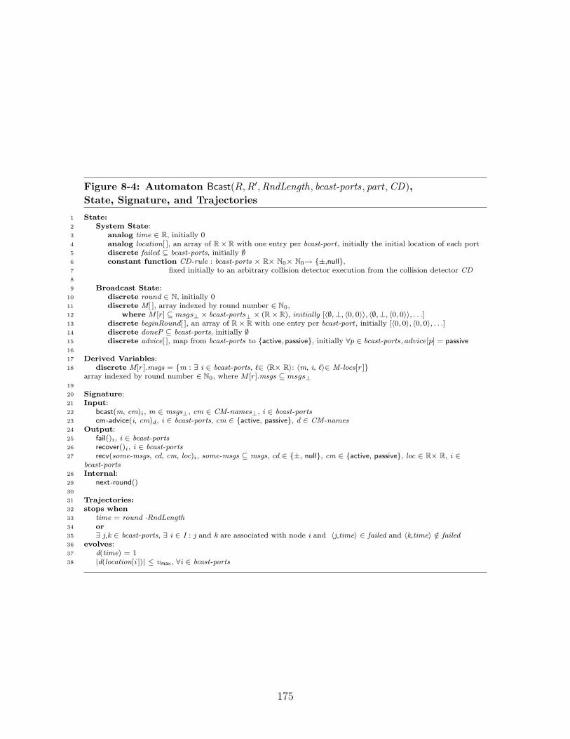
Figure 8-4: Automaton Bcast(R,R′,RndLength, bcast-ports, part ,CD),State, Signature, and Trajectories
1 State:2 System State:3 analog time ∈ R, initially 04 analog location[ ], an array of R× R with one entry per bcast-port , initially the initial location of each port5 discrete failed ⊆ bcast-ports, initially ∅6 constant function CD-rule : bcast-ports × R× N0× N0→ {±,null},7 fixed initially to an arbitrary collision detector execution from the collision detector CD8
9 Broadcast State:10 discrete round ∈ N, initially 011 discrete M[ ], array indexed by round number ∈ N0,12 where M [r] ⊆ msgs⊥ × bcast-ports⊥ × (R× R), initially [〈∅,⊥, 〈0, 0〉〉, 〈∅,⊥, 〈0, 0〉〉, . . .]13 discrete beginRound[ ], an array of R× R with one entry per bcast-port , initially [〈0, 0〉, 〈0, 0〉, . . .]14 discrete doneP ⊆ bcast-ports, initially ∅15 discrete advice[ ], map from bcast-ports to {active, passive}, initially ∀p ∈ bcast-ports, advice[p] = passive16
17 Derived Variables:18 discrete M[r ].msgs = {m : ∃ i ∈ bcast-ports, `∈ 〈R× R〉: 〈m, i, `〉∈ M-locs[r ]}
array indexed by round number ∈ N0, where M [r].msgs ⊆ msgs⊥19
20 Signature:21 Input:22 bcast(m, cm)i, m ∈ msgs⊥, cm ∈ CM-names⊥, i ∈ bcast-ports23 cm-advice(i, cm)d, i ∈ bcast-ports, cm ∈ {active, passive}, d ∈ CM-names24 Output:25 fail()i, i ∈ bcast-ports26 recover()i, i ∈ bcast-ports27 recv(some-msgs, cd, cm, loc)i, some-msgs ⊆ msgs, cd ∈ {±, null}, cm ∈ {active, passive}, loc ∈ R× R, i ∈
bcast-ports28 Internal:29 next-round()30
31 Trajectories:32 stops when33 time = round ·RndLength34 or35 ∃ j,k ∈ bcast-ports, ∃ i ∈ I : j and k are associated with node i and 〈j,time〉 ∈ failed and 〈k,time〉 /∈ failed36 evolves:37 d(time) = 138 |d(location[i ])| ≤ vmax, ∀i ∈ bcast-ports
175

Figure 8-5: Automaton Bcast(R,R′,RndLength, bcast-ports, part ,CD), Transitions
1 Input bcast(m, cm)i
2 Local State:3 r ∈ N4 Effect:5 r ← btime/RndLengthc+ 16 M[r ] ← M[r ] ∪ 〈m, i, beginRound[i ] 〉7
8 Input cm-advice(i, cm)d
9 Effect:10 if (cm = active) then11 advice[i ] ← cm12
13 Internal next-round()14 Precondition:15 doneP ∪ failed = bcast-ports16 time = round ·RndLength17 Effect:18 round ← round +119 doneP ← ∅20 ∀i ∈ bcast-ports: beginRound[i ] ← location[i ]21
22 Output fail()i
23 Precondition:24 6 ∃ t ∈ N: 〈i,t〉 ∈ failed25 Effect:26 advice[i ] ← passive27 failed ← failed ∪ 〈i, time〉28
29 Output recover()i
30 Precondition:31 ∃ t such that 〈i, t〉 ∈ failed32 time ≥ t +RndLength33 Effect:34 failed ← failed − 〈i, t〉35
36 Output recv(some-msgs, cd, cm, loc)i
37 Local State:38 sentM ⊆ msgs39 rcvedM ⊆ msgs40 sentMinterfere ⊆ msgs41 rcvedMinterfere ⊆ msgs42 Precondition:43 time = round ·RndLength44 some-msgs ⊆ M[round ].msgs − {⊥}45 if 〈m, i, ·〉∈ M[round ] then46 m ∈ some-msgs47 i /∈ doneP48 i /∈ failed49 let sentM = {m 6= ⊥: ∃ j ∈ bcast-ports, 〈m, j, ·〉∈ M[round ], |beginRound[j ] − beginRound[i ]| ≤ R}50 let rcvedM = sentM ∩ some-msgs51 let sentMinterfere = {m 6= ⊥: ∃ j ∈ bcast-ports, 〈m, j, ·〉∈ M[round ], |beginRound[j ] − beginRound[i ]| ≤ R′}52 let rcvedMinterfere = sentMinterfere ∩ some-msgs53 cd = CD-rule(i, round, |sentM|, |rcvedM|, |sentMinterfere|, |rcvedMinterfere|)54 cm = advice[i ]55 loc = location[i ]56 Effect:57 advice[i ] ← passive58 doneP ← doneP ∪ i
176

2. (Receive) Messages are delivered to the process via the action recv(M, cd , cm, loc),where M ⊆ msgs is a set of messages; cd ∈ {±, null} and cm ∈ {active, passive}are related to collision detection and contention management, respectively, andare discussed later in the section; loc ∈ (R× R) is the location of node i.
Along with coordinating the synchronous round structure, the broadcast servicehere also models portions of the environment; specifically, it is responsible for main-taining general execution information, such as the real time and the location of themobile nodes. It is convenient to model this global state as part of the broadcastservice4. Thus, the broadcast service notifies nodes when they fail, as well as simplydelivering messages.
We now discuss the parameters that define the broadcast service. The formalTIOA specification of the broadcast service is presented in Figures 8-4 and 8-5. Wethen describe the state maintained by the broadcast service, and present an overviewof the operation of the broadcast service. Finally, we argue that the broadcast serviceis a progressive timed I/O automaton.
In Section 8.1.7, we present some additional liveness properties that may be asso-ciated with the Bcast automaton.
Broadcast Service Parameters
The broadcast service is defined by six parameters:
1. R ∈ R>0, a broadcast radius governing the range of the wireless broadcast.
2. R′ ∈ R>0, R′ ≥ R, an interference radius governing how far away broadcastingnodes must be to guarantee non-interference. When R = R′ = 1, this describesthe model commonly referred to as the “unit-disc model.” When R < R′ = 1,this describes the model commonly referred to as the “quasi-unit-disc model.”
3. RndLength ∈ R>0, the length of a round. The round length should be longenough to allow a single device to broadcast a single message. For the basicbroadcast service, RndLength = 1. The virtual broadcast service will have alarger RndLength.
4. bcast-ports , the set of broadcast ports.
5. part , a partition of broadcast ports into non-intersecting sets. Conceptually,broadcasts by ports in different sets of the partition should not interfere witheach other. One could imagine different sets in the partition representing dif-ferent wireless frequencies, or different slots in a pre-allocated time-divisionschedule.
6. CD , a collision detector for bcast-ports , as described in Section 8.1.3).
4In Part I of this thesis, we referred to the combined broadcast service and GeoSensor as the“RealWorld.”
177

Broadcast Service State
Figure 8-4 presents the signature and state for the reference TIOA specification for thebroadcast service. In this section, we describe the state maintained by the broadcastservice.
We divide the state variables into two categories: (1) system state, related to thegeneral operation of the entire system, and (2) broadcast state, related to the specificoperation of the broadcast service.
First, we discuss the system state (lines 2–7, Figure 8-4). The broadcast servicemaintains information about the ongoing execution, including the current time, thelocation of the nodes, the failure status of the nodes, and the collision-detector rule:
• time is the current real time. The evolution clause d(time) = 1 (line 37, Fig-ure 8-4) indicates that it progresses at exactly the rate of real time.
• location[] is an array that maintains the exact geographical (2-space) location ofeach port in the system. These locations evolve non-deterministically, subjectonly to the restriction that the nodes may not move too fast, i.e., they havemaximum velocity vmax (line 38, Figure 8-4). Notice that the location of eachnode changes continuously; sudden jumps in the location are disallowed.
• failed is the set of nodes that are currently failed, along with the time at whichthey failed. Conceptually, a node in the system fails “atomically,” in the sensethat all the automata associated with the same node should receive fail andrecover events at the same real time. The broadcast service, however, interactswith processes on a per-port basis. The stops when condition in line 35, Figure 8-4, ensures that all the ports associated with a single node fail and recovertogether. Specifically, time cannot pass until either (1) all the ports associatedwith a given node are in the set failed , or (2) none of the ports associated witha given node are in the set failed .
• CD-rule is a specific collision detector rule chosen from the collision detectorCD , a set of collision detector rules. The CD-rule component of the state isconstant, in that it does not change during an execution. At the beginning of anexecution of the broadcast service, a specific execution of the collision detectoris fixed, non-deterministically. This modelling choice provides a simple way toallow non-determinism in the collision detector.
The second part of the state consists of the broadcast state (lines 9–9, Figure 8-4),which maintains the current round, the set of messages broadcast in each round, theset of ports that have received messages in each round, and the contention manageradvice delivered to each port. The broadcast state consists of the following compo-nents:
• The variable round maintains the current round of the execution. Round 1begins at time 0, and ends at time 1; in general, round r begins at time (r −1) · RndLength and ends at time r · RndLength. The internal action next-round
178

increments the round number when the previous round is complete. Roundsare discussed further in Section 8.1.6.
• M [] is an array with one entry for each round of the execution. The entryM [r] stores the set of messages that are broadcast in round r. Each elementin the array consists of three components: (1) a message m ∈ msgs⊥, (2) aport i ∈ bcast-ports , indicating which port broadcast message m, and (3) alocation ` ∈ R × R indicating the location of the port (as per location[] in thesystem state) which broadcast the message at the time that the message wassent. These three components provide all the necessary information about themessages sent in round r. The message array M is updated only when a bcastaction occurs. (See lines 1–6, Figure 8-4.)
We define the derived variable M [r].msgs ⊆ msgs⊥ to be the set of messages(without the associated port and location information) sent in round r. Thatis, M [r].msgs is the set {m : ∃i ∈ bcast-ports , ` ∈ 〈R× R〉 : 〈m, i, `〉 ∈M [r]}.
• beginRound [], is an array that maintains the exact location of each port in thesystem at the beginning of the current round. It is useful throughout the roundto remember where the nodes were when the round began.
• doneP is a bookkeeping variable that records the set of ports that have alreadyreceived a message in the current round. The doneP set is updated whenevera recv event occurs, delivering a message to some port. When every port haseither received a message or failed, then the round is complete. That is, whendoneP ∪ failed = bcast-ports and time has reached the end of the current round,then a next-round action can occur. (See lines 13–20, Figure 8-4.)
• advice maintains the current information on which nodes should be active, ac-cording to the contention managers. Each contention manager provides inputto the broadcast service via cm-advice(i, cm)d events, where i ∈ bcast-ports andcm ∈ {active, passive}. (See lines 8–11, Figure 8-4.) Each such event indicatesthat port i should either be active or passive in the following round. This adviceis then passed to the port itself during a recv event. (See line 54, Figure 8-4.)
Broadcast Service Transitions Overview
In this section, we provide an overview of the broadcast service transitions in Figure 8-5. We begin with the two input actions, bcast and cm-advice, followed by the internalaction next-round, and concluding with the output actions fail, recover, and recv.
Input Actions:
• The primary purpose of the broadcast service is to allow a node on someport i ∈ bcast-ports to broadcast a message: bcast(m, cm)i (lines 1–6,Figure 8-5), where m is a message in msgs⊥ and cm ∈ CM-names⊥ is arequest to a contention manager. First, the broadcast service calculates
179

the round r in which the message should be delivered (line 5, Figure 8-5), and then adds that message to the set of messages M [r]. The roundstructure is described further in Section 8.1.6.
• The input cm-advice(i, cm)d (lines 8–11, Figure 8-5) allows the contentionmanager CM d to pass information to the broadcast service. Specifically, itprovides advice cm ∈ {active, passive} with respect to port i ∈ bcast-ports .If any contention manager advises a node to be active in round r, thenadvice[i] is set to active; otherwise, it remains set to passive
Internal Actions:
• The internal action next-round (lines 13–20, Figure 8-5) advances the roundwhen two criteria are met: first, the broadcast service has delivered mes-sages for the previous round to every non-failed node, as checked by ensur-ing that every port is represented in the set doneP ∪ failed , and second, itis the correct real time for the next round to begin. This action incrementsthe round number, resets doneP to ∅, and records the locations of all theports. It is useful throughout the round to keep track of where the nodeswere at the beginning of the round.
Output Actions:
• The output actions faili (lines 22–27, Figure 8-5) and recoveri (lines 29–34,Figure 8-5) cause port i to fail and recover, respectively. Any port that isnot failed—as determined by the failed set and checked by the preconditionof the fail action—may fail at any time. Similarly, any port that has failedmore than time RndLength ago may recover. When a faili event occurs,the advice[i] is reset to passive, preparing for the possibility that node iwill recover in a later round.
Notice that both fail and recover events can only happen with finite fre-quency: each port can only fail and recover once in every round. Also,notice that fail and recover outputs occur at ports, while in the real world,one might expect all the ports associated with a given node should failand recover at the same time. This property is enforced by the stops whencondition on line 35 of Figure 8-4, which ensures that two ports associatedwith the same node share the same failure/recovery status.
• Finally we describe the receive output action which delivers messages,along with other information, at the end of each round. Specifically, thereceive action recv(some-msgs , cd , cm, loc)i (lines 36–58, Figure 8-5) deliv-ers messages and other information to port i ∈ bcast-ports . The receiveevent happens precisely at the end of each round (see Section 8.1.6). Therecv action has the following properties, as a result of its preconditions:
– The recv event occurs exactly at the end of the round (line 43, Figure 8-5).
180

– some-msgs is some subset of the messages that should be delivered inthe current round (line 44, Figure 8-5).
– If port i sends a message in round r, then port i receives its ownmessage in round r (lines 45–46, Figure 8-5).
– Messages are delivered only once in a round (line 47, Figure 8-5), andonly if port i has not failed (line 48, Figure 8-5).
– cd ∈ {±, null} indicates whether there is a collision, as determinedby the given collision detector execution (lines 49–53, Figure 8-5).The local variable sentM calculates the set of messages broadcast inround r by a node that was nearby at the beginning of the round.Specifically, for a recvi event, it includes all messages sent by a node jwhere |location[i]− location[j]| ≤ R at the beginning of round r. Thelocal variable sentMinterfere calculates the set of messages broadcastin round r by a node in the interference radius at the beginning ofthe round, that is, all messages sent by a node j where |location[i] −location[j]| ≤ R′ at the beginning of round r. The local variablercvedM calculates the subset of sentM that is delivered by the recvevent, while rcvedMinterfere calculated the subset of sentMinterferethat is delivered by the recv event.
– cm ∈ {active, passive} passes the appropriate contention managementadvice to the process (line 54, Figure 8-5). Recall that the variableadvice[i] stores the most recent advice from a contention manager.
– loc ∈ (R × R) is the current location of the port when the recv eventoccurs (line 55, Figure 8-5).
When a recvi action occurs, two state variables are modified: first, theadvice[i] is reset to passive, in preparation for the next round advice; sec-ond, the port i is added to the set doneP , which ensures that only onerecvi event can occur in the round.
In addition, we will assume that the broadcast service guarantees eventualcollision freedom, which can roughly be interpreted as guaranteeing thateventually, if only one message is sent by all neighbors of port i, then port ireceives that message. For more information on eventual collision freedom,see Section 8.1.9.
Progressive Timed Automaton
Before proceeding, we argue that the broadcast service is a progressive timed I/Oautomaton (see Definition A.2.8):
Lemma 8.1.18. Automaton Bcast(R,R′,RndLength, bcast-ports , part ,CD , update-loc)is a progressive TIOA.
Proof. First, we argue that the broadcast automaton is a TIOA. Specifically, we haveto show that it is time-passage enabled (see Definition A.2.5). (It is immediate from
181

the TIOA syntax that it is input enabled.) There are two trajectories that result intime stopping. In each case, we show that some action is enabled.
First, consider the case when: time = round ·RndLength (line 33, Figure 8-4). Inthis case, either doneP ∪ failed = bcast-ports , in which case next-round() is enabled,or recvi is enabled for i /∈ doneP ∪ failed . Specifically, notice that the action recvi isenabled when some-msgs = M [round ]− {⊥}, and cd and cm are set as per CD-ruleand advice[i].
Second, consider the case when:
∃j, k ∈ bcast-ports ,∃i ∈ I : j and k are associated with node i
and 〈j, time〉 ∈ failed
and 〈k, time〉 /∈ failed
(line 35, Figure 8-4). Specifically, the following invariant holds in every execution:∀t < time, if j and k are ports associated with some node i ∈ I, then 〈j, t〉 ∈ failedif and only if 〈k, t〉 ∈ failed . This invariant follows immediately from the stopswhen condition: consider the last time at which the invariant holds in a prefix ofthe execution, and notice that time = t until the invariant is true. Thus, assumethat j and k are ports associated with some node i ∈ I, and 〈j, time〉 ∈ failed and〈k, time〉 /∈ failed . We know that for all t′ < time, 〈k, t′〉 ∈ failed if and only if〈j, t′〉 ∈ failed . Since 〈j, time〉 ∈ failed , we know that 〈j, t′〉 /∈ failed , and hencek , t ′ /∈ failed . Thus, the event failk is enabled.
Next, we argue that the automaton is progressive (Definition A.2.8). Considersome finite interval of time [t1, t2]. Notice that the recvi action can only happenonce for each time when time = round · RndLength. Thus there are at most d(t2 −t1)/RndLengthe + 1 receive outputs for each i ∈ bcast-ports . Since bcast-ports =I × process-ports , and the sets I and process-ports are finite, bcast-ports is also finite,resulting in a finite number of receive actions. Similarly, the next-round action canoccur only once for every interval of time of length RndLength. Finally, notice thatfor each port, the number of fail events can be at most one greater than the number ofreceive events; moreover each port can only recover once every round: the preconditionensures that if a port failed at time t, it can only recover after time t + RndLength.Hence there are at most a finite number of fail and recover events.
8.1.6 General System Definition
In this section we formally define the general system as a composition of three typesof automata: processes, a broadcast service, and a set of contention managers:
Definition 8.1.19. The general system
G(I, process-ports ,msgs ,CM-names , P, A,R,R′,RndLength, part ,CD ,CM ) ,
consists of the composition of the following automata:
1. P (A, I), the set of remapped processes for 〈A, I〉,
182
2. B(R,R′,msgs ,RndLength, bcast-ports , part ,CD), the broadcast service, wherebcast-ports = I × process-ports.
3. {CM d ∈ CM |d ∈ CM-names}, the set of contention managers.
Throughout the rest of this section, we occasionally refer to a general system G,omitting the list of parameters that has already been specified above. We begin bynoting that a general system as a whole is progressive:
Lemma 8.1.20. Every general system G is a progressive timed I/O automaton.
Proof. First, notice that each individual component is a TIOA: the broadcast ser-vice, the (remapped) processes, and the contention managers. Next, notice that thebroadcast service and the contention manager are progressive. The composed setof (remapped) processes is internally progressive, since they share no input/outputactions. Thus we can conclude that the composition of the (remapped) processes,the broadcast service, and the contention managers is internally progressive by Theo-rem A.2.11. However, the final composed automaton has no input actions, since eachhas been matched with an output action during the composition. Thus the resultingautomaton is progessive.
Synchronous Round Structure
A general system implements a round-based synchronous model. In this section wediscuss the precise resulting round structure, associating each event in an execution ofgeneral system G with a round number. Throughout this section, recall that a roundr is defined as the closed interval of time [(r − 1) · RndLength, r · RndLength], as perDefinition 8.1.17. Recall also that if α is an execution of a timed I/O automaton, wesay that an event e occurs at time t in α if `time(α′) = t, where α′ is the prefix of αincluding all the events and trajectories preceding event e.
Broadcast and Receive Events. The broadcast service delivers messages pre-cisely at the end of each round:
Definition 8.1.21. For execution α of a general system G, we say that a recv(. . .)i
event at port i ∈ bcast-ports is a round r receive event if it occurs in α at timer · RndLength.
Since the broadcast service delivers messages only at the end of a round, everyreceive event is thus assigned a round number. The processes broadcast messages atthe beginning of each round:
Definition 8.1.22. For execution α of a general system G, we say that a bcast(. . .)i
event at port i ∈ bcast-ports is a round r broadcast event if it occurs in α at time(r − 1) · RndLength.
See Figure 8-6 for an illustration of how bcast and recv events are assigned to rounds.Since each broadcast happens in response to a preceding receive event (Restriction 4of processes), every broadcast event is thus assigned a round number. Notice that theround r + 1 broadcast events occur at the same time as the round r receive events.
183

Contention Manager Events. We proceed to classify the cm-advice events byround:
Definition 8.1.23. For execution α of a general system G, for r ≥ 2, we say thata cm-advice(i, cm)d event is a round r advice event if it occurs in α at time(r − 2) · RndLength.
Notice that round r advice actually arrives at the beginning of round r− 1. Thisevent is the only type of event that does not occur in the round to which it is assigned.However, a round r cm-advice event provides advice for behavior in round r, andtherefore it is assigned to round r, despite occurring in round r − 1. See Figure 8-6for an illustration of how cm-advice events are assigned to rounds.
Next Round Events. We next classify the next-round events:
Definition 8.1.24. For execution α of a general system G, we say that a next-roundevent is a round r next-round event if it occurs in α at time (r− 1) ·RndLength.
Thus, the round r next-round event occurs at the beginning of round r. SeeFigure 8-6 for an illustration of how next-round events are assigned to rounds.
Failure and Recovery Events. We next assign the failure and recover events torounds:
Definition 8.1.25. For execution α of a general system G, we say that a faili eventis a round r fail event if r is the largest round such that it occurs after a roundr next-round event. If it occurs prior to the first next-round event, i.e., the round 1next-round event, we refer to it as a round 0 fail event.
Definition 8.1.26. For execution α of a general system G, we say that a recoverievent is a round r recover event if r is the largest round such that it occurs aftera round r next-round event. If it occurs prior to the first next-round event, i.e., theround 1 next-round event, we refer to it as a round 0 recover event.
See Figure 8-6 for an illustration of how fail and recover events are assigned to rounds.
Other Events. It remains to assign the internal events of processes to rounds:
Definition 8.1.27. For execution α of a general system G, let e be an event in αthat is an action in the signature of some automaton p in P (A, I), and not classifiedby Definitions 8.1.21–8.1.26. Let i ∈ I be the mobile node identifier associated withautomaton p.
Let r be the largest integer > 0 such that for some port j ∈ process-ports, e occurseither after a round r broadcast or after a round r recover event in α on port 〈i, j〉.If no such r exists, let r = 0. We say that e is a round r process event.
184
We use the broadcast events, rather than the next-round events, to classify the eventsthat are local to a process so that it remains possible to assign rounds to events evenwhen examining a an execution restricted only to a single process automaton.
The following straightforward lemma claims that every event is assigned to someround:
Lemma 8.1.28. Let α be an execution of a general system G. Let e be an event inα. Then there is some round r ∈ N such that e is a round r event.
Proof. If e is a recv(. . .)i event, for some port i, then e is classified by Definition 8.1.21,since all receive events occur at some time r ·RndLength, by the precondition in line 43of Figure 8-5.
If e is a bcast(. . .)i event, for some port i, then there is some preceding recv(. . .)i
event—with no intervening broadcast event—according to Restriction 4(a) on pro-cesses. This preceding receive event must occur at some time r · RndLength, as justdiscussed. There are two cases: (1) `time(α) = r · RndLength, in which case thebroadcast event must occur at time r · RndLength; (2) `time(α) > r · RndLength,in which case Restriction 4(b) on processes indicates that the broadcast event mustoccur at time r ·RndLength. In either case, the broadcast event is assigned to roundr + 1.
If e is a cm-adviced event, it is assigned to a round by Definition 8.1.23, since allcm-adviced events occur immediately after bcast events, with no time passage, as perRestrictions (3) and (4) on contention managers. That is, the preceding broadcastevent specified by Restriction (3) must occur at some time r · RndLength, as justdiscussed. There are two cases: (1) `time(α) = r · RndLength, in which case theadvice event occurs at time r · RndLength; (2) `time(α) > r · RndLength, in whichcase Restriction (4) on contention managers indicates that the broadcast event mustoccur at time r ·RndLength. In either case, the advice event is assigned to round r+2by Definition 8.1.23.
If e is a next-round event, it must occur at time r · RndLength, for some r, asensured by the precondition in line 16 of Figure 8-5.
If e is a faili or a recoveri event, it must either occur after some next-round event,or prior to all next-round events, and hence is assigned a round by Definition 8.1.25or Definition 8.1.26.
If e is not one of the preceding events, it must be an event in the signature of aremapped process, and not covered by the previous cases. Thus it is assigned a roundby Definition 8.1.27.
Finite and Infinite Executions
We will often be interested in executions containing at least r rounds, for some r ≥1. Thus, we say that α is an “r-round execution” when the broadcast service hascompleted round r and advances to the next round:
Definition 8.1.29. For execution α of general system G, for r ∈ N, we say that α isan r-round execution if a next-round(r + 1) event occurs in α.
185

Notice that an r-round execution may contain events for rounds > r; when we saythat an execution α is an r-round execution, it indicates that α includes at least rrounds.
We also consider infinite executions of a general system G:Definition 8.1.30. We say that α is an infinite execution of a general system Gif it is an execution of G and also an infinite sequence of trajectories and events.
Since G is progressive, this implies that `time(α) =∞, and also that the numberof rounds in α is unbounded.
Lemma 8.1.31. Execution α is an infinite execution of a general system G if andonly if it is an execution of G and `time(α) =∞.
Proof. First, assume α is an infinite execution, i.e., an unbounded sequence of tra-jectories and actions. Since a general system is progressive, by Lemma 8.1.20, theexecution must have infinite limit time.
Next, assume α has infinite limit time. Since the round length is finite and anext-round event occurs every round, there must be an infinite number of next-roundevents, and hence an infinite number of events and trajectories in the sequence α.
Failure and Recovery
We can now refer to the round in which a process fails:
Definition 8.1.32. For any r ∈ N, for an r-round execution α of general system G,we say that node i ∈ I fails in round r if there is a round r faili event in α.
(Recall that a round r fail event for node i ∈ I occurs between the round r next-roundand round r+1 next-round events for node i.) Similarly, a node can recover in a givenround:
Definition 8.1.33. For any r ∈ N, for an r-round execution α of general system G,we say that node i ∈ I recovers in round r if there is a round r recoveri event in α.
Thus, for any given round, a node is either failed or non-failed:
Definition 8.1.34. For any r ∈ N, for any r-round execution α of general system G,we say that node i ∈ I is failed in round r if, for some rfail ≤ r, the following twoconditions hold:
1. Node i fails in round rfail .
2. For all rounds r′ such that rfail < r′ < r, node i does not recover in round r′.
For example, in Figure 8-6, we say that i is failed in rounds 4 and 5.There are two facts to note. First, if node i fails in some round rfail , it cannot
recover until round rfail + 1, due to the restriction that a node can only recover time> RndLength after it fails (line 32, Figure 8-5). Second, notice that even if node irecovers during round r, we consider node i to be failed in round r. This is becauseeven if node i recovers in round r, it does not really participate in round r as it doesnot broadcast a round r message. (In the example in Figure 8-6, this corresponds tothe fact that there is no round 5 bcasti event.)
186

8.1.7 Message Delivery Guarantees
A reliable synchronous broadcast service should guarantee that a message is deliveredin round r if and only if it was broadcast in round r. In a wireless network, the broad-cast service may not be reliable: sometimes a message from round r may be lost. Infact, communication is prone to collisions when two nearby processes broadcast atthe same time. As a result of a collision, each node can lose an arbitrary subset ofmessages that were broadcast in a round. Moreover, collisions may affect nodes in anon-uniform way: when a node broadcasts a message, some nodes may receive themessage while others may not. To this point, we have formally described a generalsystem and specified TIOA automata to model the various general system compo-nents. In this section, we discuss the precise guarantees related to which messagesare delivered.
We now discuss the basic message delivery guarantees provided by the broadcastservice: integrity, self-delivery, and per-round delivery. Then we discuss the collisiondetection properties that a general system guarantees, and prove two lemmas relatingthe completeness and accuracy of message delivery to the completeness and accuracyof the collision detector.
Integrity, Self-Delivery, and Per-Round Delivery
First, the broadcast service provides a basic integrity guarantee:
Lemma 8.1.35 (Integrity). For ever r ∈ N, for every r-round execution α of ageneral system G, for every port i ∈ bcast-ports, if recv(M, . . .)i is a round r receiveevent in α, then for every m ∈ M , a round r bcast(m, ·)j event precedes it for someport j ∈ bcast-ports.
Proof. This property is guaranteed by line 44, which ensures that each message de-livered in round r has been stored in M [r]; line 5 ensures that each message storedin M [r] was broadcast in round r.
The broadcast service also guarantees that if node i broadcasts a message in roundr, it receives its own message in round r (lines 45–46).
Lemma 8.1.36 (Self-delivery). For every r ∈ N, for every r-round execution α of ageneral system G, for every port i ∈ bcast-ports, if a round r bcast(m, ·)i event and around r recv(M, . . .)i event occurs in α, then m ∈M .
Finally, as is typical in a synchronous broadcast service, the broadcast servicedelivers messages only once in each round to each non-failed port. Thus, it shouldnot perform two recv(. . .)i events in the same round.
Lemma 8.1.37 (Per-round delivery). For any r ∈ N, for any r-round executionα of general system G, there is at most one round r recv(. . .)i event for each porti ∈ bcast-ports; there is exactly one if i is non-failed in round r.
187

Proof. First, we argue that there is at most one such receive event. The set donePtracks the set of nodes that have already been delivered messages. In line 47, thebroadcast service checks that a node has not already received messages for the currentround. In line 58, the broadcast service adds i to doneP . Finally, in line 19, thebroadcast service resets doneP to empty in preparation for the next round, andincrements the round number. Therefore there is at most one round r recv(. . .)i eventfor each port i ∈ bcast-ports .
Next, we argue that there is at least one such recv event: notice that the next-roundaction cannot execute until i ∈ doneP ∪ failed , as per the precondition in line 15.Thus, if i is non-failed, the round is not incremented until a round r recv occurs.Since α is an r-round execution, there is a r + 1 next-round event, and thus there issome round r recv(. . .)i event, for each port i ∈ bcast-ports .
In combination with Restriction 4 of processes, Lemma 8.1.37 implies that eachnon-failed port performs one broadcast in each round:
Lemma 8.1.38. For every r ∈ N, for every r-round execution α of a general systemG, for each port i ∈ bcast-ports, there is at most one round r bcast(. . .)i for port i.Moreover, if the node associated with port i does not fail in or prior to round r, thenthere is exactly one such broadcast event.
If the node associated with port i is correct, we can therefore refer to the uniqueround r bcast on port i and the unique round r recv on port i.
Collision Detector Properties
In this section, we relate the completeness and accuracy of the broadcast service tothe completeness and accuracy of the collision detector. We begin by defining whatit means for a process to detect a collision in a given round, and then present twobasic lemmas regarding when a process must detect a collision, and when a processmay detect a collision.
Detecting a Collision. Collision detection information is delivered by the broad-cast service to each mobile node as part of the recv event:
Definition 8.1.39. For every r ∈ N, for every r-round execution α of a generalsystem G, we say that port i ∈ bcast-ports detects a collision in round r when αcontains a round r recv(·,±, ·, ·)i event.
A collision detection in round r provides an indication that some message thatnode i should have received in round r was lost. It does not provide any informationwith respect to the number of lost messages or the identities of their senders.
Completeness. The broadcast service provides the following collision detectionguarantees, which reflect the completeness and eventual accuracy guarantees of thecollision detector:
188

Lemma 8.1.40 (Completeness). Assume that CD ∈ ♦A-C. For every r ∈ N, forevery r-round execution α of a general system G, for i, j ∈ bcast-ports be two broadcastports:
If there exists a round r bcast(m, . . .)j event for j in α and a round r recv(M, cd , . . .)i
event for i in α, and i and j are within distance R at the beginning of round r5 andj does not fail prior to the end of round r, then either (1) m ∈M , or (2) cd = ±.
Proof. Assume m /∈ M . Consider lines 49 and 53 of the recv action: notice thatm ∈ sentM , but m /∈ rcvedM , hence |sentM | < |rcvedM |. Since CD-rule is complete,this implies that cd = ±.
That is, in each round, if two nodes are within the broadcast radius at the begin-ning of the round and one of them broadcasts a message, then either the other nodewill receive that message or it will detect a collision.
This assumption of “perfect” completeness is quite strong. Previously [23,79], wehave examined weaker notions of completeness, such as “majority completeness” and“zero completeness.” It seems likely that all the algorithms described in this thesiscan be adapted for a majority complete collision detector6. Lower bounds in [23, 79]suggest that it is likely impossible to adapt the algorithms in this thesis for zerocomplete collision detectors. Specifically, we know that with only a zero-complete,eventually accurate collision detector, it is impossible to solve consensus efficiently;every consensus protocol requires at least a logarithmic number of rounds. We canalso conclude that it would be impossible to adapt the algorithms in this thesis for an“eventually complete” collision detector, as it is impossible to solve consensus withsuch a collision detector.
Accuracy. For eventual accuracy, we define the stabilization round racc(α), whichis the round at which the collision detector becomes stable. From racc(α) onwards,the collision detector reports a collision only when a message was, in fact lost.
Definition 8.1.41. For every infinite execution α of a general system G, defineracc(α) to be the smallest round such that for every r ≥ racc(α):
• If there exists a round r recv(M,±, . . .)i event in α for some i ∈ bcast-ports,then there exists a port j ∈ bcast-ports and m ∈ msgs such that:
1. There exists a round r bcast(m, . . .)j event in α.
2. Port j is within distance R′ of i at the beginning of round r.
3. Message m /∈M .
If no such racc(α) exists, then we define racc =∞.
5Recall that the velocity of a node is bounded by vmax, and hence this limits their distance fromeach other at the end of the round. In Section 8.2, we relate this maximum velocity to the broadcastradius.
6In [23, 79] we have shown that the problem of consensus can be solved efficiently (i.e., in O(1)time) if a system is equipped with a majority-complete, eventually accurate collision detector.
189

It then follows from the definition of eventual accuracy that such a stabilizationround exists:
Lemma 8.1.42 (Eventual Accuracy). Assume that CD ∈ ♦A-C. For every infiniteexecution α of a general system G, racc(α) is finite.
Proof. According to the definition of accuracy, there is some racc such that for allr ≥ racc, CD-rule(·, r, ·, ·, p, p) = null, for all p ∈ N0. Consider some round r ≥racc, and assume there exists a round r recv(M,±, . . .)i event in α for some i ∈bcast-ports . From the way in which cd is set in lines 51 and 53, we can conclude that|sentMinterfere| < |rcvedMinterfere| in round r. Thus there exists some messagethat was broadcast in round r by some node j that is within distance R′ of i at thebeginning of round r that is not received by node i in round r, as required. Thusracc(α) = racc.
This lemma implies that, eventually, if a node detect a collision, then it did notreceive some message sent by an interfering node.
8.1.8 Contention Manager Properties
The goal of the contention manager is to advise certain broadcast ports to be active,and other broadcast ports to be passive. The canonical contention manager—with theempty set of additional properties—defined in Section 8.1.4 simply guarantees thatsome advice is given in each round. We will be interested in this thesis in contentionmanagers that provide further guarantees as to which ports are advised to be active.In this section, we begin by defining what it means for a port to contend in a givenround, and then discuss desirable properties of contention managers.
Contending
When a port requests that a particular contention manager advise it to be active, wesay that that port is “contending:”
Definition 8.1.43. For round r ∈ N, for an r-round execution α of general system G,we say that port i ∈ bcast-ports contends for CM d in round r of α if α containsa round r − 1 broadcast event bcast(·, d)i.
Definition 8.1.44. For round r ∈ N, for an r-round execution α of general systemG, we say that port i ∈ bcast-ports contends in round r of α if it contends forsome CM d, d ∈ CM-names.
The contention manager observes the broadcast events of the processes, and canthus determine which ports are contending in a given round.
190
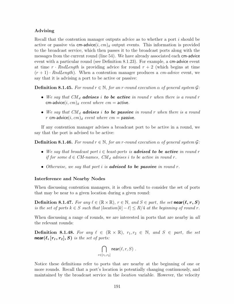
Advising
Recall that the contention manager outputs advice as to whether a port i should beactive or passive via cm-advice(i, cm)d output events. This information is providedto the broadcast service, which then passes it to the broadcast ports along with themessages from the current round (line 54). We have already associated each cm-adviceevent with a particular round (see Definition 8.1.23). For example, a cm-advice eventat time r · RndLength is providing advice for round r + 2 (which begins at time(r + 1) · RndLength). When a contention manager produces a cm-advice event, wesay that it is advising a port to be active or passive:
Definition 8.1.45. For round r ∈ N, for an r-round execution α of general system G:
• We say that CM d advises i to be active in round r when there is a round rcm-advice(i, cm)d event where cm = active.
• We say that CM d advises i to be passive in round r when there is a roundr cm-advice(i, cm)d event where cm = passive.
If any contention manager advises a broadcast port to be active in a round, wesay that the port is advised to be active:
Definition 8.1.46. For round r ∈ N, for an r-round execution α of general system G:
• We say that broadcast port i ∈ bcast-ports is advised to be active in round rif for some d ∈ CM-names, CM d advises i to be active in round r.
• Otherwise, we say that port i is advised to be passive in round r.
Interference and Nearby Nodes
When discussing contention managers, it is often useful to consider the set of portsthat may be near to a given location during a given round:
Definition 8.1.47. For any ` ∈ (R×R), r ∈ N, and S ∈ part, the set near(`, r , S)is the set of ports k ∈ S such that |location[k]− `| ≤ R/4 at the beginning of round r.
When discussing a range of rounds, we are interested in ports that are nearby in allthe relevant rounds:
Definition 8.1.48. For any ` ∈ (R × R), r1, r2 ∈ N, and S ∈ part, the setnear(`, [r1 , r2 ], S) is the set of ports:⋂
r∈[r1,r2]
near(`, r, S) .
Notice these definitions refer to ports that are nearby at the beginning of one ormore rounds. Recall that a port’s location is potentially changing continuously, andmaintained by the broadcast service in the location variable. However, the velocity
191

of a mobile node is bounded by vmax, and hence by assuming that two nodes are closeat the beginning of a round, we can conclude that they are not too far apart at theend of a round.
We may also be interested in the nodes close enough to “interfere” with a givenport’s broadcasts.
Definition 8.1.49. For any ` ∈ (R×R), r ∈ N, and S ∈ part, the set interfere(`, r , S)is the set of ports k ∈ S such that |location[k]− `| ≤ 2R′ at the beginning of round r.
Non-Interfering and Fair Contention Managers
We begin by describing a powerful—and useful—class of contention managers thatguarantee two strong properties: eventual non-interference and eventual fairness. In-tuitively, a non-interfering contention manager guarantees that it will advise only oneport in a region to be active; a fair contention guarantees that each port will getrepeated turns to be active.
Non-Interference. Ideally, only broadcast ports that are sufficiently far apartshould be activated by a contention manager. Specifically, a contention managershould ensure that, eventually, it never advises two ports withing distance 2R′ tobe active in the same round. With a non-interfering contention manager, all colli-sions can, eventually, be avoided simply by following the advice of the contentionmanager; this follows as a result of eventual collision freedom, which is discussed inSection 8.1.9.
Definition 8.1.50. Assume S ∈ part, a set of ports, and that CM is a contentionmanager in some general system G. We say that a contention manager CM is even-tually non-interfering for S if it guarantees the following property:
• For every infinite execution α of G, there exists some round rcm such that forevery round r ≥ rcm :
- For every pair of broadcast ports i, j ∈ S, if i and j are advised by CM tobe active in round r, then i /∈ interfere(location[j], r, S).
Fairness. A second desirable property of a contention manager is that it shouldeventually guarantee that each broadcast port is occasionally advised to be active.Consider the following notion of an “eventually fair” contention manager that giveseach port repeated turns to broadcast:
Definition 8.1.51. Assume d ∈ N, S ∈ part, and that CM is a contention managerin some general system G. We say that CM is eventually fair for S with delay dif it guarantees the following property:
• For every infinite execution α of G, there exists some round rcm such that forevery round r ≥ rcm :
192

- If port i ∈ S is not failed in rounds [r, r + d], then there exists a roundr′ ∈ [r, r + d] such that contention manager CM advises port i to be activein round r′ in α.
In this case, each non-failed port—that remains non-failed for sufficiently long—isguaranteed that every so often it will be designated as active. Notice that this con-tention manager does not distinguish between contending and non-contending ports;it simply gives each port turns. If the contention manager CM is also non-interfering,it guarantees that when the port is advised to be active, no other interfering port willbe activated.
Contention Fairness. A weaker notion of fairness ensures that if a broadcast portcontends for long enough, it will get a turn, i.e., it will get several consecutive roundsin which to broadcast. We therefore define a fairness property that is parameterizedby two integers 〈a, b〉: each port that contends for a consecutive rounds (withoutfailing) will be activated for b consecutive rounds. (Typically, b is much smallerthan a.)
Definition 8.1.52. Assume that CM is a contention manager in some general systemG, that a, b ∈ N, a > b, and that Rdistance > 0 ∈ R is a radius. We say that CMis eventually (a, b)-contention fair for set S ∈ part with radius Rdistance if itguarantees the following property:
• For every infinite execution α of G, there exists some round rcm such that forall rounds r ≥ rcm :
– If j ∈ bcast-ports contends for CM in rounds [r, r+a−1] and j is non-failedin rounds [r, r + a− 1], then there exists some round r′ ∈ [r, r + a− b− 1]such that CM advises j to be active in rounds [r′, r′ + b− 1], and advisesevery non-failed port within distance Rdistance of j to be passive in rounds[r′, r′ + b− 1].
Notice that in the preceding definition, since r′ ∈ [r, r+a−b−1], we can concludethat r′+b ∈ [r, r+a−1], and hence that port j is contending and non-failed throughoutthe interval [r′, r′ + b− 1].
Regional Contention Manager
In this section, we consider another contention manager that guarantees only a “re-gional” notion of eventual fairness. A regional contention manager is responsible onlyfor ports in a certain geographic region of the network. This contention managerappears easier to implement in real systems than a fair, or (a, b)-far contention man-ager, in that it only resolves contention among nodes in a single specific region, thatis, nodes that can communicate with each other.
Let ` be a location in the plane. We begin by defining what it means for anexecution to satisfy “`-restricted contention.” Conceptually, a regional contentionmanager is designed to reduce contention in some specific area of the network. Thus,
193
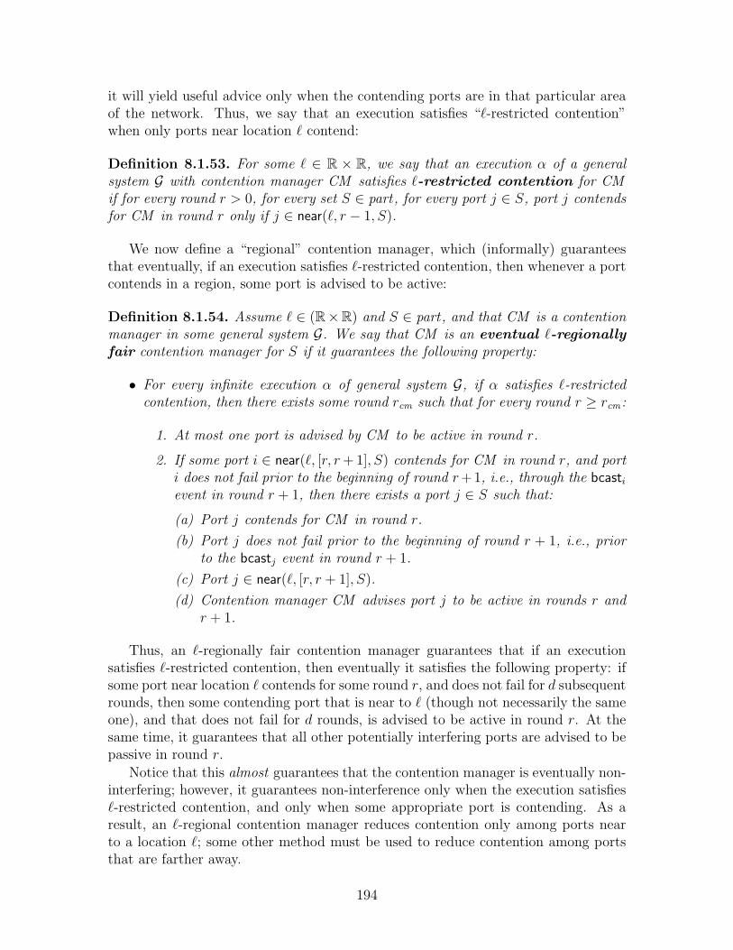
it will yield useful advice only when the contending ports are in that particular areaof the network. Thus, we say that an execution satisfies “`-restricted contention”when only ports near location ` contend:
Definition 8.1.53. For some ` ∈ R × R, we say that an execution α of a generalsystem G with contention manager CM satisfies `-restricted contention for CMif for every round r > 0, for every set S ∈ part, for every port j ∈ S, port j contendsfor CM in round r only if j ∈ near(`, r − 1, S).
We now define a “regional” contention manager, which (informally) guaranteesthat eventually, if an execution satisfies `-restricted contention, then whenever a portcontends in a region, some port is advised to be active:
Definition 8.1.54. Assume ` ∈ (R×R) and S ∈ part, and that CM is a contentionmanager in some general system G. We say that CM is an eventual `-regionallyfair contention manager for S if it guarantees the following property:
• For every infinite execution α of general system G, if α satisfies `-restrictedcontention, then there exists some round rcm such that for every round r ≥ rcm :
1. At most one port is advised by CM to be active in round r.
2. If some port i ∈ near(`, [r, r + 1], S) contends for CM in round r, and porti does not fail prior to the beginning of round r +1, i.e., through the bcastievent in round r + 1, then there exists a port j ∈ S such that:
(a) Port j contends for CM in round r.
(b) Port j does not fail prior to the beginning of round r + 1, i.e., priorto the bcastj event in round r + 1.
(c) Port j ∈ near(`, [r, r + 1], S).
(d) Contention manager CM advises port j to be active in rounds r andr + 1.
Thus, an `-regionally fair contention manager guarantees that if an executionsatisfies `-restricted contention, then eventually it satisfies the following property: ifsome port near location ` contends for some round r, and does not fail for d subsequentrounds, then some contending port that is near to ` (though not necessarily the sameone), and that does not fail for d rounds, is advised to be active in round r. At thesame time, it guarantees that all other potentially interfering ports are advised to bepassive in round r.
Notice that this almost guarantees that the contention manager is eventually non-interfering; however, it guarantees non-interference only when the execution satisfies`-restricted contention, and only when some appropriate port is contending. As aresult, an `-regional contention manager reduces contention only among ports nearto a location `; some other method must be used to reduce contention among portsthat are farther away.
194

Conservative Contention Managers
Finally, we will sometimes want to ensure that the contention managers advise abroadcast port to be active only if that port wants to be active. Notice that a faircontention manager is not “conservative” in that it activates ports in some partitionS regardless of whether they contend or not.
Definition 8.1.55. Assume that CM is a contention manager in some general systemG. We say that a contention manager CM is conservative if for every r > 0, forevery r-round execution α of G, CM advises a port to be active in round r only if itcontends for CM in round r.
8.1.9 Eventual Collision Freedom
To this point, we have no reliability guarantees on the broadcast service. In thissection, we discuss a limited reliability guarantee: eventually, if only one message issent by a neighbor of port i or i itself, then i receives that message. In fact, theguarantee is somewhat stronger in that it ensures that ports in different sets in thepartition part can broadcast at the same time without interfering with each other.
We now define the basic eventual collision freedom property. This property saysthat if a port j broadcasts a message in round r, and no interfering port broadcastsa message in round r, then all nearby ports will receive the message:
Definition 8.1.56. We say that an infinite execution α of a general system G satisfieseventual collision freedom if there exists a round rcf such that for every roundr ≥ rcf :
For all i, j ∈ bcast-ports, S ∈ part, m ∈ msgs:
– If the following conditions hold:
1. Port j broadcasts a message: A round r bcast(m, . . .)j occurs in α.
2. Port j is a neighbor of port i: |location[j] − location[i]| ≤ R at thebeginning of round r.
3. No interfering port broadcasts a message: For every port k ∈interfere(location[i], r, S), k 6= j, a round r bcast(⊥, . . .)k occurs in α.
– Then, if a round r recv(M, . . .)i occurs in α, m ∈M .
Notice that we only focus on the location of a node at the beginning of a round; sincethe maximum velocity of each node is bounded, this is sufficient to limit its locationthroughout the round.
We also introduce a slightly weaker version of eventual collision freedom, called“Eventual Collision Freedom with Good Advice” (ECF[GA]). The only difference isthat ECF[GA] guarantees successful message delivery only when the broadcastingnode complies with the advice of the contention manager; when the broadcastingnode ignores the contention manager advice, there is no reliability guarantee.
195

Definition 8.1.57. We say that an infinite execution α of general system G satisfieseventual collision freedom with good advice if there exists a round rcf suchthat for every round r ≥ rcf :
For all i, j ∈ bcast-ports, S ∈ part, m ∈ msgs:
- If the following conditions hold:
1. Port j broadcasts a message: A round r bcast(m, . . .)j occurs in α.
2. Port j is a neighbor of port i: j ∈ near(location[i], r, S)
3. No interfering port broadcasts a message: For every port k ∈interfere(location[i], r, S), k 6= j, a round r bcast(⊥, . . .)k occurs in α.
4. Port j is advised to be active: Port j is advised to be active in roundr.
- Then, if a round r recv(M, . . .)i occurs in α, m ∈M .
We will focus our attention on executions of the basic system that guaranteeeventual collision freedom. In Chapter 9, we will discuss a virtual infrastructuresystem in which every execution guarantees ECF[GA].
Notice that the eventual collision freedom property is not guaranteed by the BCastautomaton. Since it is a property that holds “eventually,” rather than perpetually, werestrict the set of executions of Bcast to satisfy Definition 8.1.56 or Definition 8.1.57.
8.1.10 A Note on Motion-controlled Devices
Throughout this section, we have defined a class of general systems in which thedevices have no control over their own motion. In some practical situations, however,a mobile device may in fact be able to control its motion. For example, a mobilerobot can direct its own motion in a suitable fashion; a vehicle may choose its ownvelocity; machines in a factory may have some autonomous control over their actions.
Moreover, some of the most compelling uses for the virtual infrastructure paradigmpresented in this thesis are those in which devices may have some control over theirmotion. For example, consider a battlefield scenario where a set of tanks wish tocoordinate their motion according to some predetermined formation; in this case, thetanks might use virtual nodes to coordinate their motion. (See [69] for an exampleof using virtual infrastructure to solve a basic coordination problem among mobilerobots.)
The model as presented in Chapter 8, however, provides no mechanism for aprocess to influence the location of a node, as maintained by the broadcast service.It is relatively straightforward to augment the general system model presented hereto include motion control. We briefly list the places in the formal model that mustbe modified.
• Process definition: First, it is necessary to augment the definition of a process(Definition 8.1.2) to include an output action, such as move(. . .), which producesmotion control signals. This information may be in the form of a velocity
196
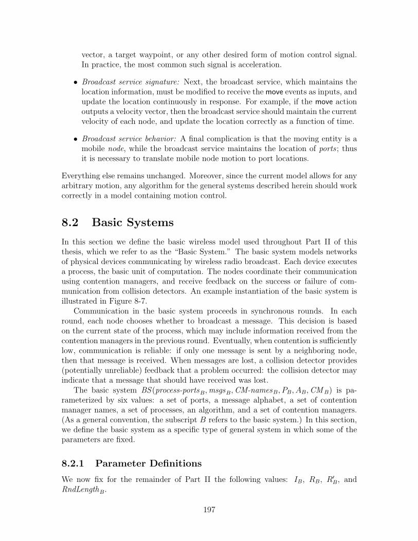
vector, a target waypoint, or any other desired form of motion control signal.In practice, the most common such signal is acceleration.
• Broadcast service signature: Next, the broadcast service, which maintains thelocation information, must be modified to receive the move events as inputs, andupdate the location continuously in response. For example, if the move actionoutputs a velocity vector, then the broadcast service should maintain the currentvelocity of each node, and update the location correctly as a function of time.
• Broadcast service behavior: A final complication is that the moving entity is amobile node, while the broadcast service maintains the location of ports ; thusit is necessary to translate mobile node motion to port locations.
Everything else remains unchanged. Moreover, since the current model allows for anyarbitrary motion, any algorithm for the general systems described herein should workcorrectly in a model containing motion control.
8.2 Basic Systems
In this section we define the basic wireless model used throughout Part II of thisthesis, which we refer to as the “Basic System.” The basic system models networksof physical devices communicating by wireless radio broadcast. Each device executesa process, the basic unit of computation. The nodes coordinate their communicationusing contention managers, and receive feedback on the success or failure of com-munication from collision detectors. An example instantiation of the basic system isillustrated in Figure 8-7.
Communication in the basic system proceeds in synchronous rounds. In eachround, each node chooses whether to broadcast a message. This decision is basedon the current state of the process, which may include information received from thecontention managers in the previous round. Eventually, when contention is sufficientlylow, communication is reliable: if only one message is sent by a neighboring node,then that message is received. When messages are lost, a collision detector provides(potentially unreliable) feedback that a problem occurred: the collision detector mayindicate that a message that should have received was lost.
The basic system BS (process-portsB,msgsB,CM-namesB, PB, AB,CM B) is pa-rameterized by six values: a set of ports, a message alphabet, a set of contentionmanager names, a set of processes, an algorithm, and a set of contention managers.(As a general convention, the subscript B refers to the basic system.) In this section,we define the basic system as a specific type of general system in which some of theparameters are fixed.
8.2.1 Parameter Definitions
We now fix for the remainder of Part II the following values: IB, RB, R′B, andRndLengthB.
197

• The set of nodes:
Definition 8.2.1. Fix IB as a finite, non-empty alphabet of names for thephysical mobile nodes.
• The broadcast and interference radii:
Definition 8.2.2. Fix RB and R′B where RB ≤ R′B and RB ≥ 20vmax .
Notice in particular the assumption that nodes cannot move too fast. Specifi-cally, we assume a relationship between their maximum velocity and the broad-cast radius RB. Thus, in five rounds, for example, a node can most a distanceof at most RB/4.
• The round length:
Definition 8.2.3. Fix RndLengthB = 1.
This normalizes the round length to 1.
• The collision detector:
Definition 8.2.4. Fix CDB to be an eventually accurate, complete collisiondetector, that is, one in the class ♦A-C.
8.2.2 Basic System Definition
In this section, we formally define the basic system as a specific type of general system:
Definition 8.2.5. Given the following parameters:
• process-portsB, a non-empty set of port identifiers,
• msgsB, a non-empty set of messages,
• CM-namesB, a finite, non-empty set of contention manager names,
• PB, a finite, non-empty set of non-recoverable processes for:
〈IB, process-portsB,msgsB,CM-namesB〉 ,
• AB, an algorithm for 〈IB, PB〉,
• CM B = {CMd : d ∈ CM-names}B, a finite, non-empty set of contention man-agers.
Define the following terms:
• Let bcast-portsB = IB × process-portsB.
198

• Let partB = {bcast-portsB}, set containing a single set of all the broadcast portsin the basic system.
The basic system BS (process-portsB,msgsB,CM-namesB, PB, AB,CM B) is definedto be general system:
G(IB, process-portsB,msgsB,CM-namesB, PB, AB, RB, R′B,RndLengthB, partB,CDB,CM B) .
Since all the processes in PB are non-recoverable, we restrict our attention in thisthesis to executions α in which for all i ∈ IB, there is at most one faili event in α.Clearly, this is without loss of generality.
We also restrict our attention to executions of the basic system that satisfy even-tual collision freedom (Definition 8.1.56).
199

⋅ ⋅ ⋅i i i
i i ii
i
Figure 8-6: Example illustrating the timing of events in a round. The diagram depictsthe first five rounds of an execution, and the dotted arrows indicate events that occurat three particular points in the execution: the end of round 2, the end of round3, and during round 5. (Other intervening events are omitted.) The index i refersto an arbitrary port in bcast-ports , and the solid arrows indicate a partial orderingon events that occur at the same instant in time. For example, the round 2 recvevent for node i necessarily precedes the round 3 bcast event for node i. Notice thatround r lasts from time (r − 1) · RndLength through time r · RndLength. The bcast,recv, and cm-advice events occur at the round boundaries. For example, at the endof round 2 (i.e., at time 2 · RndLength), the following sequence of events occurs foreach port i ∈ bcast-ports : a round 2 recv event for i, a round 3 bcast event for i,and a round 4 cm-advice event for i. The events occurs in this order (though notnecessarily consecutively). The next-round events occur at the beginning of theirrespective rounds, and necessarily follow all the recv events of the preceding round.The faili event at time 3 · RndLength is classified as a round 4 fail event as it followsthe round 3 next-round event. The recoveri event in round 5 is classified as a round5 recover event as it follows the round 5 next-round event (not depicted). Notice alsothat the round 4 bcasti event necessarily precedes the round 4 faili event, as a failedprocess does not perform a bcast event.
200

Figure 8-7: An example instantiation of the basic system, our model for wireless adhoc networks. This example system consists of four processes, that is, I = {1, 2, 3, 4}.Each process accesses the basic broadcast service via a set of process ports. In thiscase, each process has three ports, that is, process-portsB = {1, 2, 3}. The basicsystem has two contention managers, that is, CM-names = {1, 2}.
201

202

Chapter 9
Virtual Infrastructure Systems
In this chapter we describe a virtual infrastructure system, the virtual infras-tructure abstraction being discussed in Part II of this thesis. A virtual infrastructuresystem consists of clients interacting with virtual nodes via a (virtual) broadcastchannel. Virtual nodes are different from clients in two main ways. First, they arestatic: they remain in a fixed location throughout the execution. Second, virtualnodes are also recoverable: if they fail, they can resume operation at a later point, ifcircumstances allow. Our goal is that overall, virtual nodes should be more reliableand predictable.
In many ways, however, a virtual infrastructure system is quite similar to a basicsystem: each client and virtual node executes a process; the clients and virtual nodescommunicate using a wireless broadcast service; the virtual nodes and clients receiveadvice from a contention manager on how to use the broadcast channel efficiently1;the clients and virtual nodes receive feedback from a collision detector when messagesare lost.
An example virtual infrastructure system containing four clients and two virtualnodes is illustrated in Figure 9-1. It is particularly instructive to compare the systemin Figure 9-1 to the basic system illustrated in Figure 8-7; notice that the resultingstructure is quite similar, with the primary difference being the existence of virtualnodes.
We begin in Section 9.1 by defining a virtual infrastructure system. In Section 9.2,we present an example of how to design an application in the virtual infrastructuremodel. (In this case, we use the example of implementing a simple tracking service.)Finally, in Section 9.3, we discuss what it means for a protocol to implement virtualinfrastructure.
1Notice that the contention managers in the virtual system can be used much like the contentionmanagers in the basic system to decide when a node should broadcast and when a node shouldremain silent.
203
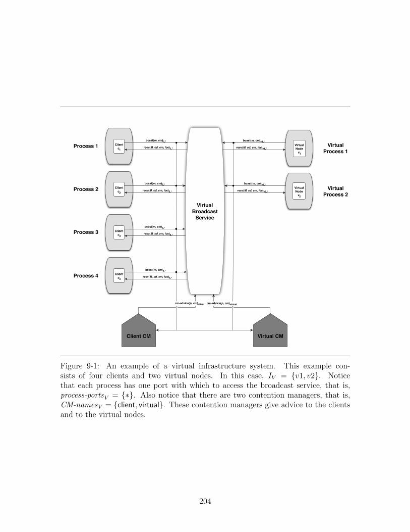
Figure 9-1: An example of a virtual infrastructure system. This example con-sists of four clients and two virtual nodes. In this case, IV = {v1, v2}. Noticethat each process has one port with which to access the broadcast service, that is,process-portsV = {∗}. Also notice that there are two contention managers, that is,CM-namesV = {client, virtual}. These contention managers give advice to the clientsand to the virtual nodes.
204

9.1 Defining Virtual Infrastructure
The virtual infrastructure system VS (IV ,msgsV , PV , AV , locV ) is parameterized byfive values: a finite set of virtual node identifiers, a message alphabet, a set of pro-cesses, an algorithm, and a mapping designating the static location of each virtualnode. (As a general convention, the subscript V refers to the virtual infrastructuresystem parameters.) In this section, we formally define the virtual infrastructure tobe a type of general system in which some of the parameters are fixed.
9.1.1 Parameter Definitions
Recall that we have already fixed certain constants in Section 8.2: IB, RB, R′B, andRndLengthB. In this section, we fix an additional set of values, those associatedwith the virtual infrastructure system, specifically, RV , R′V , process-portsV , CDV ,CM-namesV , and CM V .
• The broadcast and interference radii:
Definition 9.1.1. Fix RV and R′V where RV ≤ R′V such that:
– RV = RB/2
– R′V = RB/2 + R′B .
• The ports available to each node:
Definition 9.1.2. We fix process-portsV = {∗}, that is, the set containingthe single element ∗.
• The collision detector CDV :
Definition 9.1.3. Fix CDV to be the set of all eventually accurate, completecollision detector rules.
Notice that, by definition, CDV is in the class ♦A-C.
• The contention manager names:
Definition 9.1.4. Fix CM-namesV = {virtual, client}.
Thus, the virtual infrastructure system contains two contention managers: onecontention manager for the set of virtual nodes and one contention manager forthe set of client nodes.
• The contention managers:
Definition 9.1.5. Fix CMvirtual to be the canonical contention manager au-tomaton (see Figure 8-3) with two liveness properties: eventual non-interference,and eventual fairness for the set of ports IV × {∗}.
205

Definition 9.1.6. Fix CMclient to be the canonical contention manager au-tomaton (see Figure 8-3) with no additional liveness properties.
Notice that we do not a priori assume any liveness guarantees for the clientcontention manager. There may, however, be a subset of executions in whichthe client contention manager satisfies additional liveness properties.
The virtual infrastructure implementation discussed in Chapter 10 has theproperty that if the basic system’s contention managers satisfy a stronger live-ness property, then the client contention manager also satisfies a stronger live-ness property. As an example, we show that if a basic system contains a“global” contention manager guaranteeing (a, b)-contention fairness, then ourimplementation of virtual infrastructure guarantees that the client contentionmanager satisfies (a′, b′)-contention fairness for port set IB × {∗}, where a′ =da/RndLengthV e and b′ = bb/RndLengthV c. More generally, we will show thatif the basic system contains a “global” contention manager, then the clientcontention manager is a “sampling” of that contention manager, as per Defini-tion 11.10.9 in Chapter 11.
9.1.2 Scheduling the Virtual Nodes
One of the advantages provided by virtual infrastructure is that virtual nodes aremore predictable than real nodes; specifically, in Part II of this thesis, they are static,remaining at a fixed location throughout the execution. One use for this fact is thatwe can schedule the virtual nodes a priori so as to avoid collisions between nearbyvirtual nodes. (This schedule will be useful, for example, in constructing the virtualcontention manager.) Notice that only virtual nodes are included in the schedule;clients, which move unpredictably, might be hard to schedule efficiently.
The length of the schedule will depend on the density of the virtual node locations:if there are many virtual nodes in a small area, then the schedule will need to be longerso that each virtual node gets a turn to broadcast.
Let schedule[0..s − 1] be an array in which each entry in the array is a set ofvirtual nodes in some arbitrary set IV , and let loc be a function mapping virtualnodes in IV to a location in R×R. The integer s is the number of entries in the array.The schedule is “non-conflicting” with respect to IV and loc if no two “neighboring”virtual nodes are scheduled to broadcast at the same time:
Definition 9.1.7. We say that schedule[0..s − 1] is non-conflicting with respectto IV and loc if it satisfies the following property: ∀i ∈ [0, s − 1],∀v, v′ ∈ IV , ifv, v′ ∈ schedule[i], then |loc(v)V − loc(v′)V | > 2R′V .
That is, if virtual nodes v and v′ are in schedule[i], for some i, then virtual nodes vand v′ are not too close together. We say that the schedule is “complete” with respectto IV and loc if it includes each virtual node exactly once:
Definition 9.1.8. We say that schedule[0..s− 1] is complete with respect to IV if itsatisfies the following property: ∀v ∈ IV , there exists a unique i ∈ [0, s− 1] such thatv ∈ schedule[i].
206
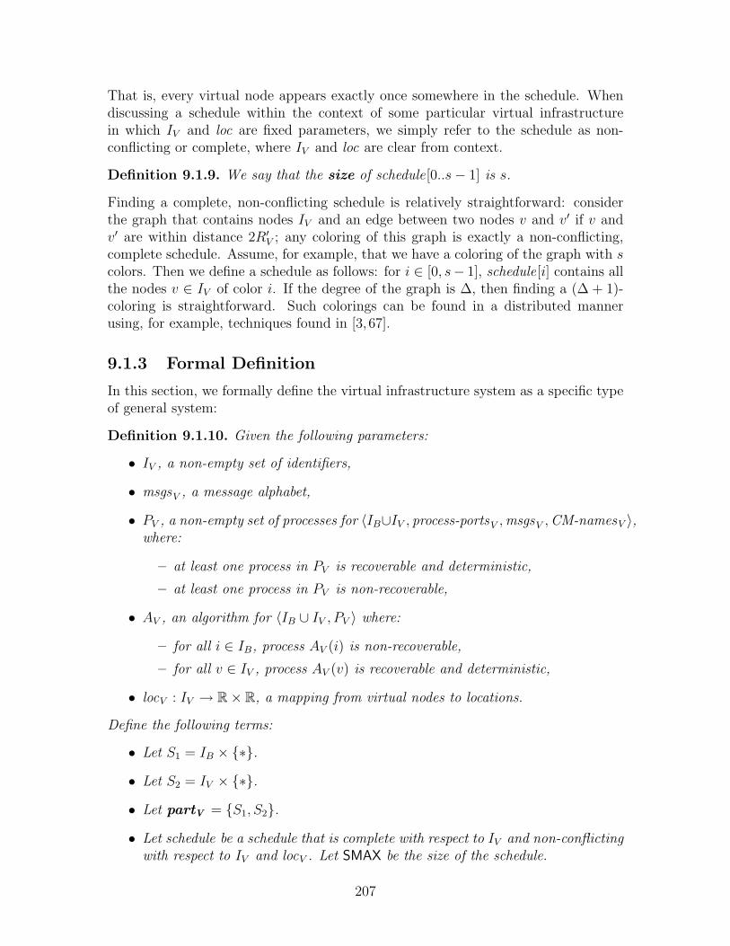
That is, every virtual node appears exactly once somewhere in the schedule. Whendiscussing a schedule within the context of some particular virtual infrastructurein which IV and loc are fixed parameters, we simply refer to the schedule as non-conflicting or complete, where IV and loc are clear from context.
Definition 9.1.9. We say that the size of schedule[0..s− 1] is s.
Finding a complete, non-conflicting schedule is relatively straightforward: considerthe graph that contains nodes IV and an edge between two nodes v and v′ if v andv′ are within distance 2R′V ; any coloring of this graph is exactly a non-conflicting,complete schedule. Assume, for example, that we have a coloring of the graph with scolors. Then we define a schedule as follows: for i ∈ [0, s− 1], schedule[i] contains allthe nodes v ∈ IV of color i. If the degree of the graph is ∆, then finding a (∆ + 1)-coloring is straightforward. Such colorings can be found in a distributed mannerusing, for example, techniques found in [3, 67].
9.1.3 Formal Definition
In this section, we formally define the virtual infrastructure system as a specific typeof general system:
Definition 9.1.10. Given the following parameters:
• IV , a non-empty set of identifiers,
• msgsV , a message alphabet,
• PV , a non-empty set of processes for 〈IB∪IV , process-portsV ,msgsV ,CM-namesV 〉,where:
– at least one process in PV is recoverable and deterministic,
– at least one process in PV is non-recoverable,
• AV , an algorithm for 〈IB ∪ IV , PV 〉 where:
– for all i ∈ IB, process AV (i) is non-recoverable,
– for all v ∈ IV , process AV (v) is recoverable and deterministic,
• locV : IV → R× R, a mapping from virtual nodes to locations.
Define the following terms:
• Let S1 = IB × {∗}.
• Let S2 = IV × {∗}.
• Let partV = {S1, S2}.
• Let schedule be a schedule that is complete with respect to IV and non-conflictingwith respect to IV and locV . Let SMAX be the size of the schedule.
207

• Let RndLengthV = SMAX + 10.
The virtual infrastructure system VS (IV ,msgsV , PV , AV , locV ) is defined to begeneral system:
G(IB∪IV , process-portsV ,msgsV ,CM-namesV , PV , AV , RV , R′V ,RndLengthV , partV ,CDV ,CM V ) ,
subject to the following additional assumptions:
• The locations of the virtual nodes are constant: for v ∈ IV , the location of IV isequal to loc(v)V .
Notice that there are two specific restrictions made on virtual nodes that arenot required of nodes in IB: (1) Their location is static, unchanging throughout theexecution, and (2) they are deterministic. Thus, given the current state of a virtualnode, there is exactly one message that it is enabled to broadcast. We claim that thisis not a severe restriction, as a non-deterministic process can be made deterministicby specifying a schedule that determines which transitions to make in which states.
Notice also that the virtual round length RndLengthV is some positive integervalue that depends on SMAX, and thus on the density of the virtual node locations:if there are many virtual nodes in a small area, then the round length will be longer;if the virtual nodes are sparsely distributed, then the round length will be shorter.
9.2 Example Virtual Infrastructure Application
In this section, we give a simple example of how to design an application for thevirtual infrastructure system. We focus on the problem of tracking the locations ofthe clients (i.e., mobile nodes). Note that this example is only for didactic purposes—the result is not particularly efficient, nor does it guarantee desirable properties likelocality of update. For a more careful location tracking system built on a (somewhatdifferent) virtual infrastructure platform, see [35,83]2. The main goal of this exampleis simplicity: it demonstrates that a relatively powerful application can be designedwith a minimum of effort.
The tracking service provides two actions with which it interacts with clients:query(j), an input which initiates a query for node j ∈ IB, and respond(j, `), anoutput which reports the most recent known location ` of node j.
The server component, running on the virtual nodes, supports two functions: aquery, indicating that a client has received a query for the location of node j ∈ IB,and update(j, `), which notifies the service of the new location ` of node j ∈ IB. Theservice fulfills these requests on a best-effort basis: when the location of a node isknown, and if this location is not too out of date, it returns the value; when thelocation of a node is unknown, then it returns nothing. Under certain assumptions,we can conclude that when the system stabilizes, each query will receive a response.
2Specifically, they focused on a virtual infrastructure layer similar to that presented in Chap-ter 5, except that the virtual nodes are timed, rather than asynchronous. They also focus onself-stabilization as an important property for an infrastructural layer.
208
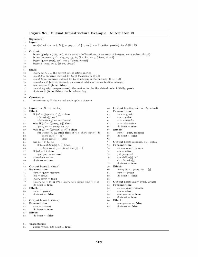
Figure 9-2: Virtual Infrastructure Example: Automaton VI
1 Signature:2 Input:3 recv(M, cd, cm, loc), M ⊆ msgsV , cd ∈ {±, null}, cm ∈ {active, passive}, loc ∈ (R× R)4
5 Output:6 bcast(〈gossip, cl, ct〉, cm), cl an array of of locations, ct an array of integers, cm ∈ {client, virtual}7 bcast(〈response, j, `〉, cm), j ∈ IB , `∈ (R× R), cm ∈ {client, virtual}8 bcast(〈query-error〉, cm), cm ∈ {client, virtual}9 bcast(⊥, cm), cm ∈ {client, virtual}
10
11 State:12 query-set ⊆ IB , the current set of active queries13 client-loc, an array indexed by IB of locations in R× R14 client-time, an array indexed by IB of integers in N0, initially [0, 0, . . . , 0]15 cm-advice ∈ {active, passive}, the current advice of the contention manager16 query-error ∈ {true, false}17 turn ∈ {gossip, query-response}, the next action by the virtual node, initially, gossip18 do-bcast ∈ {true, false}, the broadcast flag19
20 Constants:21 vn-timeout ∈ N, the virtual node update timeout
23 Input recv(M, cd, cm, loc)24 Effect:25 if (M = {〈update, `, j〉}) then26 client-loc[j ] ← `27 client-time[j ] ← vn-timeout28 else if (M = {〈query, j〉}) then29 query-set ← query-set ∪ j30 else if (M = {〈gossip, cl, ct〉}) then31 for every j ∈ IB such that ct[j ] > client-time[j ] do32 client-loc[j ] ← cl[j ]33 client-time[j ] ← ct[j ]34 for all j ∈ IB do35 if (client-time[j ] > 0) then36 client-time[j ] ← client-time[j ] − 137 if (cd = ±) then38 query-error ← true39 cm-advice ← cm40 do-bcast ← true41
42 Output bcast(⊥, virtual)43 Precondition:44 turn = query-resposne45 cm = active46 query-error = false47 (query-set = ∅) or (∀j ∈ query-set : client-time[j ] = 0)48 do-bcast = true49 Effect:50 turn ← gossip51 do-bcast ← false52
53 Output bcast(⊥, virtual)54 Precondition:55 (cm = passive)56 do-bcast = true57 Effect:58 do-bcast ← false
60 Output bcast(〈gossip, cl, ct〉, virtual)61 Precondition:62 turn = gossip63 cm = active64 cl = client-loc65 ct = client-time66 do-bcast = true67 Effect:68 turn ← query-response69 do-bcast ← false70
71 Output bcast(〈response, j, `〉, virtual)72 Precondition:73 turn = query-response74 cm = active75 j ∈ query-set76 client-time[j ] > 077 `= client-loc[j ]78 do-bcast = true79 Effect:80 query-set ← query-set − {j}81 turn ← gossip82 do-bcast ← false83
84 Output bcast(〈query-error〉, virtual)85 Precondition:86 turn = query-response87 cm = active88 query-error = true89 do-bcast = true90 Effect:91 query-error ← false92 do-bcast ← false
94 Trajectories:95 stops when: (do-bcast = true)
209

Figure 9-3: Virtual Infrastructure Example: Automaton client(i), where i ∈ IB
1 Signture:2 Input:3 recv(M, cd, cm, loc)i, M ⊆ msgsV , cd ∈ {±, null}, cm ∈ {active, passive}, loc ∈ (R× R)4
5 Input:6 query(j)i, j ∈ IB
7
8 Output:9 bcast(〈update, current-location, j〉, cm)i, current-location ∈ (R× R), j ∈ IB , cm ∈ {client,virtual}
10 bcast(〈query, j〉, cm)i, j ∈ IB , cm ∈ {client,virtual}11 bcast(⊥, cm)i, cm ∈ {client, virtual}12 response(j, `)i, j ∈ IB , `∈ (R× R)13
14 State:15 sleep ∈ N0, how long until the next update should be sent.16 query ∈ IB ∪ ⊥, a client whose location is being queried, or ⊥.17 waiting ∈ {true, false}, an indication that the query is waiting for a response.18 cm-advice ∈ {active, passive}, the current advice of the contention manager.19 current-location ∈ R× R, the current location of i.20 client-loc, an array indexed by IB of locations in R× R.21 do-bcast ∈ {true, false}, the broadcast flag.22
23 Constants:24 client-timeout ∈ N, the client update timeout
26 Input recv(M, cd, cm, loc)i
27 Effect:28 if (M = {〈response, query, `〉}) then29 client-loc[query ] ← `30 waiting ← false31 else if (M = {〈query-error〉}) then32 waiting ← false33 if (sleep > 0) then34 sleep ← sleep − 135 if ((cd = ±) and (waiting = true)) then36 waiting ← false37 cm-advice ← cm38 current-location ← loc39 do-bcast ← true40
41 Input query(j)i
42 Effect:43 query ← j44 client-loc[query ] ← ⊥45 waiting ← false46
47 Output bcast(〈update, current-location, i〉, cm)i
48 Precondition:49 sleep = 050 cm-advice = active51 if ((query 6= ⊥) and (waiting = false)) then52 cm = client53 else54 cm = ⊥55 do-bcast = true56 Effect:57 sleep ← client-timeout58 do-bcast ← false
60 Output bcast(〈query, j〉, ⊥) i
61 Precondition:62 sleep 6= 063 cm-advice = active64 query = j65 waiting = false66 do-bcast = true67 Effect:68 waiting ← true69 do-bcast ← false70
71 Output bcast(⊥, cm)i
72 Precondition:73 (cm-advice = passive)74 or75 ((sleep 6= 0) and ((query = ⊥) or (waiting = true)))76 if (waiting = true) or (sleep = 0) then77 cm = client78 else79 cm = ⊥80 do-bcast = true81 Effect:82 do-bcast ← false83
84 Output respond(j, `)i
85 Precondition:86 j = query87 client-loc[j ] = `88 Effect:89 client-loc[j ] ← ⊥90 waiting \ets false91 query ← ⊥
93 Trajectories:94 stops when: (do-bcast = true)
210
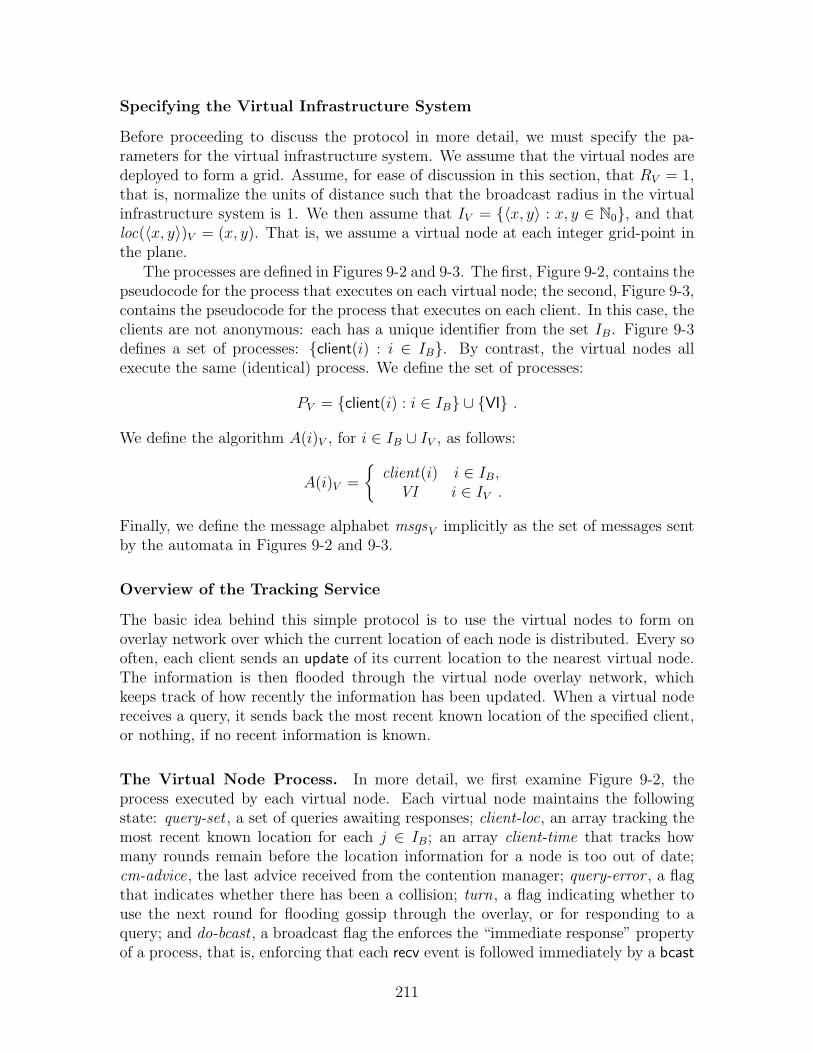
Specifying the Virtual Infrastructure System
Before proceeding to discuss the protocol in more detail, we must specify the pa-rameters for the virtual infrastructure system. We assume that the virtual nodes aredeployed to form a grid. Assume, for ease of discussion in this section, that RV = 1,that is, normalize the units of distance such that the broadcast radius in the virtualinfrastructure system is 1. We then assume that IV = {〈x, y〉 : x, y ∈ N0}, and thatloc(〈x, y〉)V = (x, y). That is, we assume a virtual node at each integer grid-point inthe plane.
The processes are defined in Figures 9-2 and 9-3. The first, Figure 9-2, contains thepseudocode for the process that executes on each virtual node; the second, Figure 9-3,contains the pseudocode for the process that executes on each client. In this case, theclients are not anonymous: each has a unique identifier from the set IB. Figure 9-3defines a set of processes: {client(i) : i ∈ IB}. By contrast, the virtual nodes allexecute the same (identical) process. We define the set of processes:
PV = {client(i) : i ∈ IB} ∪ {VI} .
We define the algorithm A(i)V , for i ∈ IB ∪ IV , as follows:
A(i)V =
{client(i) i ∈ IB,
VI i ∈ IV .
Finally, we define the message alphabet msgsV implicitly as the set of messages sentby the automata in Figures 9-2 and 9-3.
Overview of the Tracking Service
The basic idea behind this simple protocol is to use the virtual nodes to form onoverlay network over which the current location of each node is distributed. Every sooften, each client sends an update of its current location to the nearest virtual node.The information is then flooded through the virtual node overlay network, whichkeeps track of how recently the information has been updated. When a virtual nodereceives a query, it sends back the most recent known location of the specified client,or nothing, if no recent information is known.
The Virtual Node Process. In more detail, we first examine Figure 9-2, theprocess executed by each virtual node. Each virtual node maintains the followingstate: query-set , a set of queries awaiting responses; client-loc, an array tracking themost recent known location for each j ∈ IB; an array client-time that tracks howmany rounds remain before the location information for a node is too out of date;cm-advice, the last advice received from the contention manager; query-error , a flagthat indicates whether there has been a collision; turn, a flag indicating whether touse the next round for flooding gossip through the overlay, or for responding to aquery; and do-bcast , a broadcast flag the enforces the “immediate response” propertyof a process, that is, enforcing that each recv event is followed immediately by a bcast
211
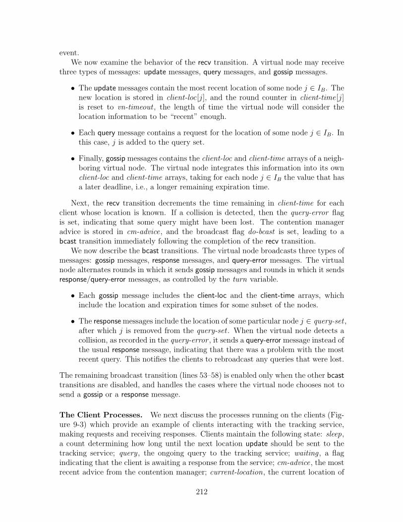
event.We now examine the behavior of the recv transition. A virtual node may receive
three types of messages: update messages, query messages, and gossip messages.
• The update messages contain the most recent location of some node j ∈ IB. Thenew location is stored in client-loc[j], and the round counter in client-time[j]is reset to vn-timeout , the length of time the virtual node will consider thelocation information to be “recent” enough.
• Each query message contains a request for the location of some node j ∈ IB. Inthis case, j is added to the query set.
• Finally, gossip messages contains the client-loc and client-time arrays of a neigh-boring virtual node. The virtual node integrates this information into its ownclient-loc and client-time arrays, taking for each node j ∈ IB the value that hasa later deadline, i.e., a longer remaining expiration time.
Next, the recv transition decrements the time remaining in client-time for eachclient whose location is known. If a collision is detected, then the query-error flagis set, indicating that some query might have been lost. The contention manageradvice is stored in cm-advice, and the broadcast flag do-bcast is set, leading to abcast transition immediately following the completion of the recv transition.
We now describe the bcast transitions. The virtual node broadcasts three types ofmessages: gossip messages, response messages, and query-error messages. The virtualnode alternates rounds in which it sends gossip messages and rounds in which it sendsresponse/query-error messages, as controlled by the turn variable.
• Each gossip message includes the client-loc and the client-time arrays, whichinclude the location and expiration times for some subset of the nodes.
• The response messages include the location of some particular node j ∈ query-set ,after which j is removed from the query-set . When the virtual node detects acollision, as recorded in the query-error , it sends a query-error message instead ofthe usual response message, indicating that there was a problem with the mostrecent query. This notifies the clients to rebroadcast any queries that were lost.
The remaining broadcast transition (lines 53–58) is enabled only when the other bcasttransitions are disabled, and handles the cases where the virtual node chooses not tosend a gossip or a response message.
The Client Processes. We next discuss the processes running on the clients (Fig-ure 9-3) which provide an example of clients interacting with the tracking service,making requests and receiving responses. Clients maintain the following state: sleep,a count determining how long until the next location update should be sent to thetracking service; query , the ongoing query to the tracking service; waiting , a flagindicating that the client is awaiting a response from the service; cm-advice, the mostrecent advice from the contention manager; current-location, the current location of
212

node i; client-loc remembers the locations of the virtual nodes, as per the most re-cent queries; and do-bcast , a broadcast flag the enforces the “immediate response”property of a process, that is, enforcing that each recv event is followed immediatelyby a bcast event.
We now describe the recv transition. A client receives two types of messages fromthe server process running on the virtual nodes: response messages and query-errormessages.
• The response messages indicate that a query is complete, returning the resultof a location query. In this example, these responses are stored in the client-locarray.
• The query-error messages indicate that the virtual node has detected a collision;thus, if there is an ongoing query, it may not have received the query. Thus, inthis case, the query is resent, as is indicated by setting waiting to false.
Next, the clients update the sleep counter, decrementing it by one. (The sleep countercontrols the frequency with which the clients update the virtual nodes with theirlocation.) Next, clients use their collision detectors to determine whether a responsefrom a virtual node has been lost. When a client detects a collision, it resends thequery to the virtual node, in case the virtual node sent a response that was lost dueto a collision.
We now describe the bcast transitions. Clients broadcast two types of messages:update messages and query messages.
• Periodically, clients send update messages to the tracking service. When thevariable sleep reaches zero, then it is time to send a new update. The maximumvalue of sleep is client-timeout , which determines the frequency of the periodicupdates. Notice that messages are sent only when the contention managerdesignates the node as active.
• Every so often, a client may receive a query input, which sets query to somearbitrary node j ∈ IB, and sets waiting to false, thus initiating a query. At thispoint, the client sends a query message to the server component of the trackingservice. Notice that the query message is sent only in a round in which sleep 6= 0,that is, in a round that is not already designated for an update message, andalso only if the contention manager designates the node as active.
The remaining bcast transition (lines 71–82) is enabled only when the other bcasttransitions are disabled, and handles the cases where the client chooses not to send aquery or an update message.
Performance of the Simple Tracking Application
Under certain assumptions, the tracking application guarantees that eventually, oncethe network stabilizes, each location query gets a response containing the approximatelocation of the queried node. We first enumerate the relevant assumptions. Notice
213

that to a large extent these numbers are chosen arbitrarily. It matters only that thevn-timeout is large enough with respect to the client-timeout , the diameter of thenetwork, and the delays of the two contention managers.
• First, assume that the size of the network is bounded by some D (for diameter);specifically, assume that there are no mobile nodes outside of the square in thereal plane defined by 〈(0, 0), (D, D)〉. Thus, each message can travel from oneend of the network to the other in time ≤ 2D.
• Assume that the client contention manager guarantees eventual (50D, 1)-cont-ention fairness (see Definition 8.1.52).
• Assume that R′V = 4.
• Assume that the virtual contention manager is eventually fair with delay 25(see Definition 8.1.51). (Notice that it is easy to construct a schedule for thevirtual nodes of size 25, since the virtual node network is a grid, and R′V = 4.)
• Assume that client-timeout ≤ 50D.
• Assume that vn-timeout > 200D.
• Assume that none of the virtual nodes fail.
In this case, we can conclude that eventually, each query receives a response.First, notice that once the network stabilizes, we can conclude that some virtualnode receives a location update from each node every 100D rounds. Specifically, theclient-timeout ensures that after 50D rounds, the client begins to request access tothe broadcast channel; since the channel is (50D, 1)-contention fair, we can concludethat within a further 50D rounds, the client receives authorization to broadcast withno interference. By eventual collision freedom, we can conclude that the virtual nodereceives this messages. Thus every 100D rounds, some virtual node receives a locationupdate for each client.
Next, we notice that it takes a further 100D rounds for the information to dis-seminate through the network. Each virtual node broadcasts a gossip message atleast once every 50 rounds: it receives a turn from the fair contention manager every25 rounds, and it broadcasts a gossip message every two turns. Again, by eventualcollision freedom we can conclude that this gossip message is received. Within 2Dhops, the gossip message propagates throughout the network. Since each hop takesat most 50 rounds, we can conclude that within 100D rounds, the gossip has spreadthroughout the network.
Thus we conclude that every 200D rounds, every virtual node receives an updatefor each client’s location. Since the vn-timeout > 200D, this is sufficient to ensurethat each virtual node maintains a valid estimate of each client’s location.
The overall delay for a query of the tracking service depends on how many con-current queries occur: recall that the virtual node only responds to one query in around in which it sends a response. (A simple optimization, of course, would allow
214

the virtual node to send multiple query responses in one round.) Assume there are noconcurrent queries; a query will then complete after stabilization in 50D +50 rounds:within 50D rounds, the client is authorized by the contention manager to broadcastits query; within a further 50 rounds, the virtual node sends a response. Assumingthere are at most k concurrent queries, the delay is 50D + 50k rounds.
Finally, notice that given a bound on the velocity of a client, we can calculatethe accuracy of the location information. Specifically, we know that |location[i] −query(i)| ≤ 200D · vmax .
9.3 Simulating Virtual Infrastructure
Our goal in building virtual infrastructure is to emulate a virtual system using abasic system. Thus, given values for the parameters which specify a virtual infras-tructure system—IV , PV , AV , locV ,msgsV —we want to construct a basic system—process-portsB,msgsB,CM-namesB, PB, AB,CM B—that is, in a sense, indistinguish-able from the virtual infrastructure system. For the remainder of this thesis, we fix theset of virtual infrastructure parameters: IV , msgsV , PV , AV , locV , and we fix a spe-cific instantiation of the virtual infrastructure system VS (IV ,msgsV , PV , AV , locV ).In this section, we discuss what it means to correctly simulate the virtual infrastruc-ture system in a basic system.
First, recall that, informally, a virtual infrastructure system consists of clients andvirtual nodes communicating using a virtual broadcast channel. Formally, we referto the set of processes running on nodes in IB as “clients”:
Definition 9.3.1. Given a virtual infrastructure system, the set of client processesis {AV (i) : i ∈ IB}.
We refer to the set of processes running on virtual nodes as “virtual processes:”
Definition 9.3.2. Given a virtual infrastructure system, the set of virtual pro-cesses is {AV (w) : w ∈ IV }.
Our goal in simulating virtual infrastructure is to ensure that client processesbelieve that they are operating in a virtual infrastructure system. Each client broad-casts and receives messages as if the system contains actual virtual nodes; an emulatoracts as an intermediary between the client and the basic broadcast service, providingthe illusion that virtual nodes really exist. Figure 9-4 depicts the situation in whicheach client interacts with an emulator (depicted as Ai in the figure), and togetherthe clients and emulators form processes that communicate using the basic broadcastservice. In Sections 10.1 and 10.2, we present an “emulator” of this sort.
The emulator should guarantee a “trace inclusion” property for the clients: forevery “trace” of the clients in the basic system, there should exist an execution of thevirtual infrastructure system with the same “trace.”
We now discuss the notion of trace inclusion in more detail. Given an execution ofa virtual infrastructure system GV , consider the events observable by the clients withthe real times at which they occur. In other words, consider a timed execution of
215

BasicBroadcast
Service
Emulator E
Client c1
bcast(m, cm)1,*
recv(M, cd, cm, loc)1,*
bcast(m, cm)1,v
recv(M, cd, cm, loc)1,v
bcast(m, cm)1,v'
recv(M, cd, cm, loc)1,v'
bcast(m, cm)1,0
recv(M, cd, cm, loc)1,0
Client c2 Emulator
E
bcast(m, cm)2,*
recv(M, cd, cm, loc)2,*
bcast(m, cm)2,v
recv(M, cd, cm, loc)2,v
bcast(m, cm)2,v'
recv(M, cd, cm, loc)2,v'
bcast(m, cm)2,0
recv(M, cd, cm, loc)2,0
Client c3 Emulator
E
bcast(m, cm)3,*
recv(M, cd, cm, loc)3,*
bcast(m, cm)3,v
recv(M, cd, cm, loc)3,v
bcast(m, cm)3,v'
recv(M, cd, cm, loc)3,v'
bcast(m, cm)3,0
recv(M, cd, cm, loc)3,0
Client c4 Emulator
E
bcast(m, cm)4,*
recv(M, cd, cm, loc)4,*
bcast(m, cm)4,v
recv(M, cd, cm, loc)4,v
bcast(m, cm)4,v'
recv(M, cd, cm, loc)4,v'
Contention Manager 2
Contention Manager 1
cm-advice(p, cm)2cm-advice(p, cm)1
Process 1
Process 2
Process 3
Process 4bcast(m, cm)4,0
recv(M, cd, cm, loc)4,0
Figure 9-4: An overview of the emulator system. Emulator E is an algorithm thatimplements the virtual infrastructure system (depicted in Figure 9-1) on top of thebasic system (depicted in Figure 8-7). Each client is composed with emulator E toform a process, and these processes are executed in the basic system. We say thatemulator E implements the specified virtual infrastructure system if the clients cannotdistinguish whether they are executing in the basic system, as in the figure above,or in the virtual infrastructure system (Figure 9-1). That is, emulator E implementsthe virtual infrastructure system when every trace of the clients in the basic systemis a trace of the clients in the virtual infrastructure system.
216

the virtual system, consisting of clients, virtual nodes, the broadcast service, and thecontention managers, in which all the events except the client broadcast and receiveevents are hidden. We define the set of hidden actions as follows:
HV = GV .actions − {bcasti,∗ : i ∈ IB} − {recvi,∗ : i ∈ IB} .
Notationally, we refer to the set of externally-visible, timed client traces as the fol-lowing: traces(hideHV
(GV )). Thus, the only actions visible in the trace are bcasti,∗ :i ∈ IB and recvi,∗ : i ∈ IB.
Similarly, given an execution of the basic system GB, consider the events observableby the clients with the real times at which they occur. In this case, we are consideringa timed execution of the clients, the emulator automata, the broadcast service, andthe contention managers, with all events except the client broadcast and receive eventshidden. We define the set of hidden actions as follows:
HB = GB.actions − {bcasti,∗ : i ∈ IB} − {recvi,∗ : i ∈ IB} .
Notationally, we refer to the set of externally-visible, timed client traces as the fol-lowing: traces(hideHB
(GB).When we say that the clients cannot distinguish between the basic system and the
virtual infrastructure system, we mean that every event observed in the basic systemis consistent with an execution of the virtual infrastructure system. Formally, then,we want to show that:
traces(hideHB(GB) ⊆ traces(hideHV
(GV )) .
Finally, we want our emulator to have certain good properties. For example, alegal behavior in the virtual infrastructure system is for all the virtual nodes to failat time 0 and never recover. We will show in Chapter 11 under what conditions ouremulator guarantees virtual nodes to be alive. We also want the emulator to sendsmall messages and introduce limited communication overhead. We discuss thesedesiderata in more detail when presenting the emulator algorithm.
217

218

Chapter 10
Emulating Virtual Infrastructure
In this section we present an algorithm that implements a virtual infrastructure sys-tem. We begin in Section 10.1 with an overview of the basic algorithm. In Sec-tion 10.2, then, we present a detailed description of the emulator protocol. Thepseudocode for the algorithm is presented in Figure 10-2–13.
10.1 Algorithm Overview
In order to emulate a single virtual node at location `, we replicate the virtual node atevery device within distance RB/4 of location `.1 By replicating the data at each of theparticipating nodes, we guarantee robustness in a dynamic, fault-prone environment.As mobile nodes join and leave the system, and as they enter and leave the relevantregion near to `, they participate—and cease participating—in the emulation. Werefer to mobile nodes that are active in the simulation of some virtual node v—alongwith the emulator processes that execute on them—as replicas for v.
The key difficulty in emulating some particular virtual node v is maintainingconsistency among the replicas of v. In an ideal world, the replicas responsible foremulating virtual node v would maintain identical copies of the virtual node’s state.When the execution begins, this is trivially accomplished: each replica is initializedwith the initial state of virtual node v. As the execution progresses and the virtualnode sends and receives messages, the replicas must remain consistent.
Recall that in each (virtual) round, clients broadcast messages to the virtualnode, and the virtual node broadcasts messages to the clients. If all the replicasreceive the same set of messages in a (virtual) round, then they can maintain identicalcopies of the virtual node’s state: since the virtual node is deterministic, if all thereplicas receive the same messages in a round, each replica can process the messagesand consistently update the replicated state. (In Part I of this thesis, we presenteda strategy for implementing virtual infrastructure that operates along these lines.)Unfortunately, as has been discussed in Part II of this thesis, the wireless broadcast
1In the terminology from Part I, we would refer to the circle of radius RB/4 around location `as the focal point region.
219
channel is unreliable. As a result, we cannot be sure that replicas receive the samemessages in a round: some replicas may receive a message, others may not.
10.1.1 Consensusand the Impossibility of Perfect Consistency
One way to maintain consistency among the replicas of a virtual node would be to runa consensus protocol for each round of the virtual node; the replicas could then agreeon which messages the virtual node receives (and sends) in each (virtual) round. Inthe same way, they could agree on the other parameters that are part of a recv action,i.e., the collision detection information cd and contention management informationcm for the virtual node. By repeatedly running consensus, the replicas could emulatea sequence of rounds. Moreover, as was described in [23,79]2, there is a very efficientalgorithm for consensus when collision detectors guarantee (perfect) completeness andeventual accuracy. In fact, each instance of consensus terminates in 3 rounds once thenetwork has stabilized, that is, after eventual collision freedom (round rcf ), eventualaccuracy (round racc), and eventually good contention management (round rcm).
Unfortunately, the consensus protocol is efficient only after the network has stabi-lized. Thus, the virtual infrastructure will behave poorly prior to stabilization sincethe length of a virtual round depends on the length of the consensus protocol. Specif-ically, the length of a (virtual) round would vary unpredictably. (Recall in Chapter 9,we present a virtual infrastructure in which virtual rounds have a constant length.)
This unpredictability would have many negative consequences. First, it wouldcomplicate the synchronization among virtual nodes in the virtual infrastructure layer.If the (virtual) rounds have a fixed length, it is easy to ensure that all virtual nodes areexecuting the same (virtual) round at the same time. On the other hand, if virtualrounds have an unpredictable length, then some virtual nodes may execute muchmore rapidly than others, leading to added complexity in programming the virtualinfrastructure. Instead of emulating a synchronous abstraction, the result would bean asynchronous (virtual) network, possibly with some variety of eventual synchronyguarantees.
A second negative consequence would be the difficulty in implementing timing-dependent algorithms. Many applications for virtual infrastructure involve interac-tions with the real world: for example, coordinating mobile nodes, collecting sensordata, or controlling tiny actuators. These real-world tasks are highly-timing depen-dent, and often have real-time deadlines. If (virtual) round lengths are unpredictable,it is much more difficult (and sometimes impossible) to implement such algorithms.For example, if a virtual node is attempting to collect data from a sensor, and needsto correlate the stream of sensor data with other virtual nodes, it is important thatthe sensor readings be taken at appropriate intervals of time. If some sensor readingscannot be measured (due to collisions and other network instability), it is often betterto record the fact that the measurement failed, rather than sampling the sensor at
2In [23], see Algorithm 1, and a performance evaluation in Figure 1(a). In [79], see Algorithm 1,Section 7.1.
220

the wrong time. Similarly, in the case of coordinating actuators, it is often better torespond to instability (perhaps by performing some reasonable default action), thanto simply wait for the network to stabilize.
A natural question, then, is whether some improved consensus algorithm couldguarantee constant-round termination even during the unstable parts of the execu-tion. Unfortunately, as was shown in [23, 79], it is impossible in the wireless settingto achieve consensus in a constant number of communication rounds while collisionscontinue to occur. Yet in order to implement a virtual infrastructure as described inChapter 9, we require every simulated round to terminate in a constant number ofcommunication rounds. That is, we want the RndLengthV for the virtual broadcastservice to be constant. Thus, using consensus as a black-box building block is infeasi-ble. Moreover, the protocol presented in this chapter implements each virtual roundin a constant number of basic rounds (specifically, SMAX + 10 basic rounds); thus wecan conclude that the protocol will not be able to guarantee that the replicas agreeon the state of a virtual node at the end of each virtual round.
10.1.2 Agreeing on Virtual Node Executions
To overcome this seeming impossibility, we consider a weaker notion of consistency.Instead of trying to ensure consistency at the end of each virtual round, we allow somedisagreement among the replicas, particularly during periods when the network isunreliable. We guarantee consistency only when the network is stable. This weakenedguarantee is sufficient to build a virtual infrastructure that appears consistent fromthe clients’ perspective, as the clients receive messages from the virtual nodes onlywhen the network is stable. This realization is one of the key insights in circumventingthe seeming impossibility.
In Section 10.1.1, we discussed a strategy in which the replicas attempt in eachround to agree on a set of messages to receive in that round. The algorithm presentedin this chapter uses a slightly different approach. Instead of agreeing only on a set ofmessages in each round, the replicas for each virtual node attempt to agree on a (finite)execution of the virtual node. (Recall from Appendix A that an execution is simply asequence of trajectories and actions, satisfying appropriate properties.) Moreover, ourgoal is to design an agreement protocol that uses only a bounded number of rounds inthe emulation of each virtual round. At the end of the agreement protocol—i.e., aftersome bounded number of rounds—a replica may be in one of three states: it maybe certain that agreement has been achieved; it may be certain that agreement hasnot been achieved; or it may be uncertain as to whether or not agreement has beenachieved. The key requirement is that the executions agreed upon in each round—when agreement occurs—converge to a single execution. (This property is capturedby Lemma 11.7.19 in Chapter 11.)
There is one further aspect of the agreement protocol worth noting at a high level.Unlike a traditional consensus protocol which requires that some node broadcast acomplete proposal, the agreement protocol does not require the replicas to send aproposal containing the entire execution. A proposal of this sort would, obviously, bemuch too large. Instead, the agreement protocol broadcasts information only on the
221

current (virtual) round, and a small amount of summary information regarding priorvirtual rounds. This compressed proposal is an important technical tool which makesthis protocol feasible, and the constant-sized protocol messages are a key contributionof this protocol.
Thus, the main technical challenge solved by the protocol in this paper is to agreesequentially on the outcome of each (virtual) round, that is, to agree on an execution,by performing a series of constant-round agreement instances, one for each round,while sending only constant-sized messages, and yet guaranteeing that eventually thereplicas converge to a single execution that is consistent for all the replicas.
10.1.3 Outline of the Protocol
The emulation protocol for a single virtual node consists of eleven phases. Ten ofthese phases are implemented using a single basic round each; one of these phasesis implemented using SMAX basic rounds, where SMAX is the size of a complete,non-conflicting schedule for the virtual nodes (see Definitions 9.1.7–9.1.9; recall thatthe schedule is only for virtual nodes). This results in a virtual round length ofRndLengthV = 10 + SMAX, as specified in Chapter 9.
We now briefly describe the eleven phases. For the purpose of this description,consider the case where the replicas are emulating some virtual round r for somevirtual node v. In this case, the agreement protocol is trying to agree on an executionup until the end of round r, and at the same time is trying to ensure that all thereplicas have enough information about round r for the use of future instances ofthe agreement protocol. The protocol divides into four sections: the message pro-tocol (phases 1–2), the scheduled agreement instance (phases 3–5), the unscheduledagreement instance (phases 6–8), and the join protocol (phases 9–11):
The Message Protocol:
1. client: In the client phase, each client broadcasts its message for the currentvirtual round r.
2. vn: In the vn phase, emulators for virtual node v decide whether v shouldbroadcast a message in virtual round r, and under certain conditions, broadcastthat message. This decision depends on the outcome of the prior agreementprotocols, the contention manager, etc.
The Scheduled Agreement Instance:
3. scheduled-ballot: This phase begins the first of two agreement instances thatoccur during virtual round r. Each replica participates in only one of the twoagreement instances, depending on the schedule: if v ∈ schedule[r mod SMAX]3,
3The attentive reader may notice that, since rounds start with 1, while the schedule begins withan index of 0, that the first round actually uses the second slot in the schedule. This anomalyintroduces no problems, and we leave it for simplicity of notation.
222

then v’s replicas participate in the scheduled-ballot instance; otherwise they par-ticipate in the unscheduled-ballot instance. In this phase, the replicas partici-pating in the first agreement instance may broadcast a “ballot,” which containsinformation about round r, along with some summary information about priorrounds.
4. scheduled-veto-1: This phase is the second round in the first agreement instance.In this phase, replicas for v broadcast veto messages if the agreement protocolappears to be failing.
5. scheduled-veto-2: This phase is the last round in the first agreement instance.In this phase, replicas for v again broadcast veto messages if the agreementprotocol appears to be failing.
The Unscheduled Agreement Instance:
6. unscheduled-ballot: This phase begins the second of two agreement instancesthat occur during virtual round r. Replicas that did not participate in the sched-uled agreement instance participate in the unscheduled agreement instance.That is, if v /∈ schedule[r mod SMAX], then v’s replicas participate in the un-scheduled instance. In this phase, the replicas participating in this agreementinstance may broadcast a ballot. This phase is implemented by SMAX basicrounds. The replicas for virtual node v participate in only one of these basicrounds, however. Specifically, fix rb ∈ [0, SMAX − 1, where rb identifies thecurrent basic round within the unscheduled-ballot phase; if v ∈ schedule[rb], andif v /∈ schedule[r mod SMAX − 1], then the replicas for virtual node v partic-ipate in the rth
b basic round in the unscheduled-ballot phase. During the otherbasic rounds in the unscheduled-ballot phase, the replicas for virtual node v donothing.
7. unscheduled-veto-1: This phase is the second round in the second agreementinstance. In this phase, replicas for v broadcast veto messages if the agreementprotocol appears to be failing.
8. unscheduled-veto-2: This phase is the last round in the second agreement in-stance. In this phase, replicas for v again broadcast veto messages if the agree-ment protocol appears to be failing.
The Join Protocol:
9. join: This phase begins the join protocol. A replica for virtual node v maybroadcast in this round if it wants to join the emulation.
10. join-ack: This phase is the second round of the join protocol. A replica that hasalready joined virtual node v may send a join response in this round, providingcritical information to joining nodes.
223
11. join-veto: This phase is the last round of the join protocol. In this phase, areplica for virtual node v can determine whether the virtual node should bereset. A virtual node should be reset only when there are no replicas that havealready completed the join protocol, which indicates that the virtual node hasfailed.
In Sections 10.1.5–10.1.7, we describe each of these phases in more detail. First,however, we discuss a critical aspect of the system: the implementation of the virtualcontention managers.
10.1.4 The Virtual Contention Managers
Along with delivering messages and collision information, the virtual broadcast servicealso delivers contention management information to the clients and virtual nodes. Re-call (from Chapter 9) that the virtual infrastructure system has two contention man-agers: a global contention manager for the clients, and a virtual contention managerfor the virtual nodes. Implementing the client contention manager is straightforward,and will be discussed later: the broadcast service simply delivers to the clients theadvice from one of the contention managers in the basic system (the “client contentionmanager”), sampling the advice from the basic contention manager once per virtualround—during the client phase.
The virtual contention manager, however, is emulated by the protocol presentedin this chapter. Recall that the virtual contention manager should be fair and non-interfering: each virtual node should get a turn every so often to be active, and notwo nearby virtual nodes should be active at the same time.
We build this contention manager using the schedule that we have already as-sumed: since the virtual nodes reside at known, pre-determined locations, we canexplicitly schedule them in advance. Since the schedule is non-conflicting, the re-sulting contention manager is non-interfering. Since the schedule is complete, theresulting contention manager is fair.
Given such a schedule, we fix an ideal and fair contention manager as follows:virtual node v is advised to be active in virtual round r if and only if v ∈ schedule[rmod SMAX]. It is easy to verify that the resulting contention manager has the de-sired properties. Moreover, it is easy for the emulator at each replica to calculateexactly what the advice should be for the virtual node, independent of the success—or failure—of communication with the other replicas.
The schedule determines which agreement instance replicas participate in: if v is“scheduled”, then virtual node v is advised to be active in round r and the replicas forv use the scheduled agreement instance; if v is “unscheduled”, then virtual node v isadvised to be passive in round r and the replicas for v use the unscheduled agreementinstance.
10.1.5 The Message Protocol
The purpose of the first two phases is for the clients and the replicas to broadcastthe messages that are intended to be broadcast in a given virtual round, according
224

to the process automata. In the client phase of virtual round r (i.e., the first phase),each client broadcasts its message for round r, or nothing (⊥), if it has no round rmessage.
In the vn phase, each emulator for each virtual node v decides whether v shouldbroadcast a message in round r. Throughout the execution, each emulator for vmaintains a preferred execution for v. During good periods, when agreement holds,the replicas will all have the same preferred execution; during intervals when thenetwork is unstable, the preferred executions may differ.
In order to decide whether to broadcast in the vn phase, a replica examines itspreferred execution, and determines whether the virtual node is enabled to broadcastin the last state of that execution, and if so, what message it is enabled to broadcast.(Since the virtual node is deterministic, this is a deterministic choice based only onthe state of the virtual node at the end of the preferred execution.)
A replica also examines two other factors related to contention management: (1) Isthe replica itself advised by the basic system contention manager to be active in thecurrent basic round? (2) Is the virtual node advised to be active in the current virtualround r?
If virtual node v is scheduled, a replica for v broadcasts a message m during thevn phase under the following conditions:
• The replica is advised to be active by a contention manager.
• The state of the virtual node, as calculated according to the replica’s “preferredexecution,” is such that the virtual node is enabled to broadcast the message m.
If virtual node v is not scheduled, however, then the replica’s decision as to whether tobroadcast does not depend on the advice of the contention managers. That is, if thestate of the virtual node, as calculated according to the replica’s preferred execution,”is such that the virtual node is enabled to broadcast the message m, then the replicabroadcasts message m in the vn phase.
This rule may seem counterintuitive, as it ignores the contention manager whenthe virtual node is unscheduled4. This is almost guaranteed to result in a collisionduring the vn phase, which may seem undesirable and inefficient. However, thisbehavior is consistent with the ECF[GA] guarantee that the emulator is providing inits implementation of the virtual broadcast service: since the virtual node is enabledto broadcast a message, and since the virtual node is deterministic, the virtual nodewill broadcast a message in the current virtual round; since this violates the advice ofthe contention manager, the broadcast service is not required to deliver the message.Specifically, recall that the virtual broadcast service guarantees to deliver messagesreliably only when virtual nodes comply with the advice of the contention manager.
4An alternate and seemingly simple solution would be to require nodes to follow the advice ofthe contention manager. However, it is often quite useful for protocols to sometimes ignore thecontention manager. For example, in the protocol presented in this chapter, the contention manageris sometimes ignored—specifically in the veto rounds.
225
10.1.6 The Scheduled and Unscheduled Agreement Instances
The emulation protocol consists of two agreement instances: the scheduled and un-scheduled agreement instances. As mentioned previously, the emulator for virtualnode v participates in the scheduled agreement instance if v is scheduled for round r,and in the unscheduled agreement instance otherwise. In both instances of the agree-ment protocol, the primary purpose is to agree on which messages to receive, andwhether or not to detect a collision. In the case of the scheduled agreement instance,an additional outcome is a decision as to whether or not the virtual node shouldbroadcast a message. Finally, when agreement is reached, all incomplete agreementinstances from previous rounds are resolved.
The agreement protocol is a modified version of the consensus protocol in [23,79]that provides more information on the status of other replicas, and is amenable tosmaller message sizes. The basic wireless consensus protocol in [23, 79] uses tworounds: a data round, in which the proposal is broadcast, and a veto round in whicha negative acknowledgment is broadcast if anything went wrong in the data round.The agreement protocol here uses three rounds: a data round and two veto rounds.
In some ways, the agreement protocol can be seen as an implementation of “three-phase commit” (3PC), a classic protocol for atomic commit first introduced in [95,96].In the language of three-phase commit, in each instance of the agreement protocolthe nodes try to “commit” to that virtual round, or “abort” the round. When theprotocol “commits” or “aborts” successfully, every participating node is aware of theresult. On the other hand, in some instances, due to lost messages, the protocolmay not “commit” or “abort.” The result is that some nodes end the round inan intermediate state, unsure of whether the round will eventually be accepted orrejected. If there were only two phases (i.e., one veto phase), then it would not bepossible to later reconstruct a consistent commit/abort decision for the round. Thethird phase allows a later “recovery” protocol to retroactively determine whether theround was accepted or rejected.
This analogy is not exact for several reasons. The main difference is that theagreement problem is somewhat different from classical atomic commit. First, thegoal is to agree on some set of messages (and other information) for the round, ratherthan to simply commit or abort a transaction; in that sense, the agreement problem ismore similar to consensus. Second, the goal is to agree on the behavior in a sequenceof virtual rounds. Unlike in traditional three-phase commit, where the system issuspended to run the recovery protocol, in the agreement protocol presented here,the “recovery” protocol is integrated into the main protocol itself: virtual roundscontinue to be emulated, even as prior virtual rounds are still being resolved. Thisleads to additional difficulties, since the result of earlier virtual round affects theoutcome of later virtual rounds.
We now continue to describe the protocol in more detail. Each agreement instancebegins with a ballot phase in which zero, one, or more, replicas broadcast a “proposal.”A replica’s proposal is in fact a compact representation of its preferred execution; wediscuss later the details of this representation.
To gain additional information about the success or failure of the agreement in-
226
stance, the virtual node emulator uses two veto rounds, instead of one. (Thus, thereare three phases total.) The status of each virtual round is determined by the success(or failure) of these veto rounds. Each replica designates the status of each virtualround by one of four colors: green, yellow, orange, or red.
• Green: A green round indicates that agreement has been achieved, and thatthe replicas have agreed on an execution of the virtual node. In this case, thevirtual broadcast service may deliver messages to the clients. If an emulatordesignates a round as green, it can be certain that the round is “successful.”(This is analogous to a “commit” in the case of atomic commit.)
• Yellow: A yellow round indicates that every replica at least received the currentproposal, which is guaranteed to be unique, but replicas may still disagree onthe execution. Even so, it is acceptable for a replica to include messages fromthe current round in its preferred execution (which may become the proposal infuture rounds). If an emulator designates a round as yellow, it cannot determinewhether or not the round is “successful.”
• Orange: An orange round indicates that some replicas may have received thecurrent proposal, but some may not have. When a replica designates a round asorange, it may not include messages from that round in its preferred execution,as some other replicas may not have received the proposal and thus may not havethose messages. If these messages were used in a future proposal, it would beimpossible to represent the proposal compactly. On the other hand, if a replicadesignates a round as orange, then it remains possible that some other replicamay in the future propose an execution including messages from this round. Ifan emulator designates a round as orange, it cannot determine whether or notthe round is “successful.”
• Red: Finally, a red round indicates that the current agreement instance failed,and no messages from this round will be included in any future execution.In particular, some replicas—perhaps all—may not have received the currentproposal. If an emulator designates a round as red, it can be certain the roundis not “successful.” (This is analogous to an “abort” in the case of atomiccommit.)
Thus, the round color reflects each replica’s local knowledge about the other replicas’knowledge of the emulated virtual rounds. The two veto phases, along with the ballotphase, determine the color designation of the round. If a replica receives exactlyone ballot, no veto messages, and there are no collisions in any of the rounds, thenthe replica designates the virtual round as green. Conversely, if a replica does notreceive exactly one ballot or detects a collision in the ballot round, then the replicadesignates the virtual round as red. Intermediate levels of success result in the yellowand orange designation: if there is a collision or veto in the first veto round, then thereplica designates the round as orange; if there is a collision or veto in the secondveto round, then the replica designates the round as yellow. This is summarized inFigure 10-1.
227

ballot veto-1 veto-2 Replica Color√ √ √
Green√ √
X Yellow√
X X OrangeX X X Red
Figure 10-1: Table indicating how a node responds to collisions in the different phasesof the algorithm: ballot/veto-1/veto-2. A check (
√) indicates that the node receives
a message in that round, and no collisions or veto indications are received. AnX indicates that the node does not correctly receive the message in that round.The Color column indicates the designated color for a round. Green/yellow roundsindicate (tentatively) that a message may be processed, while orange/red roundsindicate (tentatively) that the virtual node has detected a collision.
One of the key invariants of our protocol is that any two replicas disagree onthe color designation by at most one shade. For example, if replica i designatesa round as green, then every other replica must designate the round as green oryellow. Similarly, if replica i designates a round as red, then every other replica mustdesignate the round as orange or red. This limited form of disagreement is key to thecorrectness of the emulation protocol.
A final issue related to the agreement instances is the composition of the ballots:one of the key properties of the protocol is that the ballot does not have to be toobig, even though it is proposing agreement on some execution history. The ballot,then, includes two pieces of information: (1) information about the current virtualround, including any messages received in the client and vn phases, and any collisiondetected in the client and vn phases, and (2) a pointer to the most recent seemingly“good” round, that is, the most recent virtual round designated by the replica asgreen or yellow.5
When a set of replicas executes a sequence of such agreement instances, one foreach virtual round, they can use this information to construct a preferred executionof the virtual node. In rounds that are “good,” the preferred execution includes arecv event containing the messages specified by the ballot; in rounds that are “bad,”the preferred execution includes a recv event containing an empty set of messages,and a collision. The replicas use the previous-round pointer in the ballots to deter-mine which rounds are “good” and which rounds are “bad.” These pointers createa “linked-list” of pointers in the ballot history, and when two replicas agree on thislinked-list of pointers, they agree on their preferred execution.
5When considering analogies to three-phase commit, there are some similarities between theadditional information included in the ballot, and the additional information introduced by Dolevand Keidar in their “Enhanced Three Phase Commit” protocol [47]. In their protocol, each nodemaintains a variable last-elected , which keeps track of the most recent recovery attempt that thenode coordination, and last-attempt , the most recent recovery attempt in which the node attemptedto commit or abort.
228
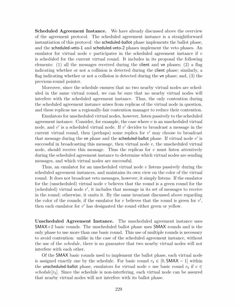
Scheduled Agreement Instance. We have already discussed above the overviewof the agreement protocol. The scheduled agreement instance is a straightforwardinstantiation of this protocol: the scheduled-ballot phase implements the ballot phase,and the scheduled-veto-1 and scheduled-veto-2 phases implement the veto phases. Anemulator for virtual node v participates in the scheduled agreement instance if vis scheduled for the current virtual round. It includes in its proposal the followingelements: (1) all the messages received during the client and vn phases; (2) a flagindicating whether or not a collision is detected during the client phase; similarly, aflag indicating whether or not a collision is detected during the vn phase; and, (3) theprevious-round pointer.
Moreover, since the schedule ensures that no two nearby virtual nodes are sched-uled in the same virtual round, we can be sure that no nearby virtual nodes willinterfere with the scheduled agreement instance. Thus, the only contention duringthe scheduled agreement instance arises from replicas of the virtual node in question,and these replicas use a regionally-fair contention manager to reduce their contention.
Emulators for unscheduled virtual nodes, however, listen passively to the scheduledagreement instance. Consider, for example, the case where v is an unscheduled virtualnode, and v′ is a scheduled virtual node. If v′ decides to broadcast a message in thecurrent virtual round, then (perhaps) some replica for v′ may choose to broadcastthat message during the vn phase and the scheduled-ballot phase. If virtual node v′ issuccessful in broadcasting this message, then virtual node v, the unscheduled virtualnode, should receive this message. Thus the replicas for v must listen attentivelyduring the scheduled agreement instance to determine which virtual nodes are sendingmessages, and which virtual nodes are successful.
Thus, an emulator for an unscheduled virtual node v listens passively during thescheduled agreement instances, and maintains its own view on the color of the virtualround. It does not broadcast veto messages, however; it simply listens. If the emulatorfor the (unscheduled) virtual node v believes that the round is a green round for the(scheduled) virtual node v′, it includes that message in its set of messages to receivein the round; otherwise, it omits it. By the same invariant discussed above regardingthe color of the rounds, if the emulator for v believes that the round is green for v′,then each emulator for v′ has designated the round either green or yellow.
Unscheduled Agreement Instance. The unscheduled agreement instance usesSMAX+2 basic rounds. The unscheduled ballot phase uses SMAX rounds and is theonly phase to use more than one basic round. This use of multiple rounds is necessaryto avoid contention: unlike in the case of the scheduled agreement instance, withoutthe use of the schedule, there is no guarantee that two nearby virtual nodes will notinterfere with each other.
Of the SMAX basic rounds used to implement the ballot phase, each virtual nodeis assigned exactly one by the schedule. For basic round rb ∈ [0, SMAX − 1] withinthe unscheduled-ballot phase, emulators for virtual node v use basic round rb if v ∈schedule[rb]. Since the schedule is non-interfering, each virtual node can be assuredthat nearby virtual nodes will not interfere with its ballot phase.
229

All the virtual nodes share the same two veto phases. Thus when a virtual nodefails to reach agreement, it may also interfere with its neighboring virtual nodes.
The ballot and veto phases then proceed as discussed above in the scheduled agree-ment instance. The ballot includes all the messages received and collisions detectedin the client phase, along with the messages received in the vn phase. (In fact, theset of messages received is modified by the outcome of the scheduled ballot instance.)That is, as in the scheduled ballot instance, the replicas are agreeing on the set ofmessages to receive and whether or not to detect a collision.
10.1.7 The Join and Restart Protocols
The last three phases are dedicated to the join protocol, which allows new replicas tojoin in the emulation, and also allows replicas to reset the virtual node when it hasfailed.
In order to join a virtual node emulation, a new replica must synchronize withthe existing replicas. A node chooses to join the virtual node emulation when it iswithin distance RB/4 of the virtual node location. (In practice, a hysteresis zone isrecommended, though not necessary, as it prevents frequent entrance and departureby nodes near the edge of a region.) In the join phase of the protocol, a node broad-casts a request to join the emulation. If a replica that has already joined receivesa join request, and if the contention manager advises that replica to be active, thenit broadcasts its current protocol state in the join-ack phase, thus giving the joiningnode an up-to-date snapshot of the current status of the emulation.
As before, we must contend with the interference between different replicas fornearby virtual nodes. Imagine that two physical nodes try to join two differentvirtual nodes in the same region. These two nodes may interfere with each other.We therefore use the schedule to mediate between the different virtual nodes, so thatemulators for neighboring virtual nodes do not disrupt each other’s join protocols,ensuring that each emulator receives an opportunity to join its virtual node.
Occasionally, a virtual node may fail when all the replicas leave the region. Wewant the virtual node to restart in a default initial state when some mobile nodesreenter the region. Moreover, we want to ensure that the replicas maintain a consistentstate, despite the occasional restart.
The key difficulty here is ensuring that the virtual node really is uninhabited;if some replica is active, and a new mobile node attempts to “restart” the virtualnode, then there is a risk that the virtual node’s state is unnecessarily lost, and thepossibility of inconsistency. By resetting a virtual node only if it is abandoned (i.e.,failed), it is relatively easy to maintain a consistent state among the replicas.
We use the join-veto phase to detect a failed virtual node. Specifically, in thejoin-veto phase, each node that has already joined broadcasts a message. (This isin fact likely to cause a collision, if there is more than one participating replica.) Anew joining node is then aware that it should not reset the virtual node. (One mightconsider an optimized version of the protocol that reduces the number of join-vetomessages by requiring replicas to broadcast in the join-veto phase only when somenode wants to perform a reset.)
230

One additional detail is needed: a reset can occur only in a round in which virtualnode v is scheduled. This means that each virtual node has a chance to execute itsjoin-veto round without interference from nearby virtual nodes and nearby join-vetomessages. Thus, a functioning virtual node will not prevent a neighboring virtualnode from being reset.
10.2 Virtual Infrastructure Emulator
In this section, we discuss the detailed implementation of the virtual infrastructureemulator. We first discuss the basic structure of the emulator, and its interfacewith clients and the broadcast service (see Section 10.2.1). We then discuss thestate maintained by the virtual node emulator (see Section 10.2.2). Next, we de-tail the main algorithm itself (see Section 10.2.3). Then, we present some helperfunctions used by the algorithm (see Section 10.2.4), and an auxiliary component,the virtual node multiplexer (see Section 10.2.5). We conclude (Section 10.2.6) withthe full specification of the emulator basic system, that is, we fix the parametersPB, process-portsB,msgsB, AB,CM-namesB,CM B.
10.2.1 Virtual Infrastructure Emulator:Structure and Signature
Our goal is to build an emulator that acts as an intermediary between the clients andthe broadcast service, and emulates a virtual infrastructure system. To this end, themain purpose of this section is to describe such an emulator automaton E.
In order to build a basic system that emulates a virtual infrastructure system, eachclient process is composed with emulator E, forming a new process that is executedin the basic system. (See Figure 9-4 for an illustration of the emulator automatoncomposed with a client to form a process.) Thus, the emulator provides a singlebroadcast/receive port to the client, and interacts with a set of broadcast/receiveports provided by the broadcast service BB. Recall that the port set of the virtual in-frastructure system, process-portsV = {∗}; thus, each client has a broadcast port withthe subscript ∗. The emulator’s port to the client, then, has the same subscript, ∗.
The emulator itself is a composition of two types of a components: individual“virtual node emulators”, each of which emulates one virtual node, and a “multi-plexer” which connects the virtual node emulators to the client. (See Figure 10-3 foran illustration of the emulator components, their ports, and their interactions withthe client.) We refer to the first automaton as E(v), for v ∈ IV , and the second asMultiplexer .
The main body of this section is presenting the emulator process(es). (If thevirtual system being emulated is anonymous, there will be only one process.) Recallthat a system is instantiated by remapping processes, disambiguating the automatabased on the nodes on which they are running. Thus, the process specification doesnot include any reference to a particular node i ∈ IB.
231

Figure 10-2: Automaton E(v): Virtual Node Emulator —Signature and Data Structures
94 Signature:95 Input:96 recv(allM, cd, cm, loc)v , allM ⊆ msgsB , cd ∈ {±, null}, cm ∈ {true, false}, loc ∈ R× R97 fail()98
99 Output:100 vn-client-output(vnm-out, vnCD-out)v , vnm-out ∈ {〈vn, m, `〉: m ∈ msgsV , `∈ R× R}⊥, vnCD ∈ {±, null}101 bcast(m, cm)v , m ∈ msgsB , cm ∈ CM-namesB ∪ {⊥}102
103 State:104 Emulator Data Structures:105 rnd ∈ N0, initially 0106 phase ∈ {client, vn, scheduled-ballot, scheduled-veto-1, scheduled-veto-2, unscheduled-ballot, unscheduled-veto-1,107 unscheduled-veto-2, join, join-ack, join-veto, initially client108 ballot[ ], an array indexed by N of ⊥ or records with the following fields:109 prev-rnd ∈ (N0)⊥, initially ⊥110 clientM ⊆ msgsB , initially ∅111 clientCD ∈ {±, null}, initially null112 vnM ⊆ msgsB , initially ∅113 vnCD ∈ {±, null}, initially null114 round-status[ ], array indexed by N of 〈green, yellow, orange, red,⊥〉, initially [⊥,⊥, . . . ,⊥]115 last-reset ∈ N0, initially 0116 last-good-state ∈ states, initially startv , the initial state for virtual node v117 prev-rnd ∈ N0⊥, initially ⊥118
119 Round-Specific Data Structures:120 clientM ⊆ msgsB , initially ∅121 vnM ⊆ msgsB , initially ∅122 clientCD ∈ {±, null}, initially null123 vnCD ∈ {±, null}, initially null124 roundCM ∈ {active, passive}, initially passive125 vnphaseBcast ∈ {true, false}, initially false126 reset ∈ {true, false}, initially false127 scheduled ∈ {true, false}, initially false128 scheduled-status ∈ {green, yellow, orange, red, ⊥}, initially ⊥129
130 Control Data Structures:131 outgoing-msg ∈ msgsB ∪ {⊥}, initially ⊥132 do-net-bcast ∈ {true, false}, initially false133 do-client-recv ∈ {true, false}, initially false134 unscheduled-ballot-rnd ∈ [0, SMAX ], initially 0135 failed ∈ {true, false}, initially false136
137 Join Protocol Data Structures:138 joined ∈ {true, false}, initially false139 join-req ∈ {true, false}, initially false140
141
142 Constants:143 δv , transition function for virtual node v ∈ IV
144 loc(v)V : IV → R× R, location of virtual node v ∈ IV
145 RB ∈ R, broadcast radius for basic broadcast service146 RB
′ ∈ R, interference radius for basic broadcast service147 RV ∈ R, broadcast radius for virtual broadcast service148 R′V ∈ R, interference radius for virtual broadcast service149 schedule[0..SMAX-1 ], schedule array, where schedule[r ] ⊆ IV and150 (1) ∀r ∈ [0..SMAX-1 ], ∀v,w ∈ schedule[r ], |loc[v ] -loc[w ]| ≥ 2R′
151 (2) ∀v ∈ IV , ∃ r ∈ [0..SMAX-1 ] such that v ∈ schedule[r ]152
153 Trajectories:154 stops when:155 ((do-net-bcast = true) or (do-client-recv = true))156 and157 (failed = false)
232

Figure 10-3: Detailed view of a process in the emulator system. The emulator Econsists of two types of components: (1) a set of virtual node emulators E(v), eachof which is responsible for emulating one virtual node V ∈ IV , and (2) a multiplexerthat mediates communication between the client and the virtual node emulators. Theemulator is composed with the client to form the process that is executed in the basicsystem.
233

Virtual Node Emulator. Each individual virtual node emulator E(v) is respon-sible for replicating one particular virtual node v ∈ IV . See the signature of E(v) onlines 94–101 in Figure 10-2. Each individual virtual node emulator has access to oneport on the wireless broadcast service:
• Input recv(. . .)v,
• Output bcast(. . .)v
Each virtual node emulator also outputs information to the client, acting as afilter between the broadcast channel and the client. Specifically, the virtual nodeemulator sends information via vn-client-output(. . .)v events to the multiplexer, whichamalgamates the information from the various virtual node emulators, and passes iton to the client process itself.
An individual virtual node emulator has one other input, fail, which indicateswhen the mobile node on which the process executes has failed.
Multiplexer. The multiplexer relays the client’s broadcasts to the broadcast ser-vice, and collects information from the virtual node emulators to pass on to the client.The signature of the multiplexer can be found in Figure 10-13 on lines 637–646. Themultiplexer communicates with the client via a broadcast/receive port:
• Input bcast(. . .)∗
• Output recv(. . .)∗.
(Recall that the index “∗” is a special literal, that is, process-portsV = {∗}.) Similarly,it communicates directly with the broadcast service via another broadcast/receiveport:
• Output bcast(. . .)0
• Input recv(. . .)0.
Finally, it receives information from the virtual node emulators:
• Input vn-client-output(. . .)v.
The multiplexer also has an input fail.In Sections 10.2.2, 10.2.3 and 10.2.4, we discuss the virtual node emulator. In
Section 10.2.5, we discuss the multiplexer.
10.2.2 Virtual Node Emulator Data Structures
In this section, we present the various data structures used by the virtual node em-ulator. The pseudocode can be found in Figure 10-2 on lines 104–150. Throughoutthis section, we discuss the individual virtual node emulator E(v) for virtual nodev ∈ IV .
234

Emulator Data Structure:
• rnd : The main goal of the virtual node emulator is to determine which messagesshould be sent and received by the virtual node in a given round. The variablernd keeps track of the current (virtual) round being emulated. (The actualround number in the underlying basic system is larger, as per the correspondencediscussed in Section 10.1.) Initially, rnd = 0.
• phase: The protocol executes in phases, and the variable phase keeps track ofthe current phase. There are eleven different phases:
1. client, 2. vn,3. scheduled-ballot, 4. scheduled-veto-1,5. scheduled-veto-2, 6. unscheduled-ballot,7. unscheduled-veto-1, 8. unscheduled-veto-2,9. join, 10. join-ack,11. join-veto.
Initially, phase = client. These phases can be divided into four groups: the firsttwo phases are for the clients and replicas to perform their broadcasts for thevirtual round; the next three phases are for the scheduled agreement protocol;the next three phases are for the unscheduled agreement protocol; the final threephases are for the join protocol.
• ballot : The primary task of the virtual node emulator is to agree on an ac-ceptable execution history. The key data structure in maintaining the differentviable execution histories is the ballot array (see lines 108–113, Figure 10-2).Each entry in the array holds a record containing information about a singlesimulated round. Each record contains five fields:
– prev-rnd , a round number,
– clientM , a set of messages,
– clientCD , either ± or null,
– vnM , a set of messages, and
– vnCD , either ± or null.
The record for simulated round r, which we refer to as a ballot, is stored inballot [r]. That is, the array of ballots is indexed by N.
The ballot specifies which messages the virtual node v should receive from clientsin round r in the clientM field, and collision detection information related tonodes in the “client” set of the partition for round r in the clientCD field. Theballot specifies which messages the virtual node v should receive from othervirtual nodes in round r in the vnM field, and collision detection informationfor nodes in the “virtual nodes” set of the partition for round r in the vnCDfield.
235

Each ballot also contains some additional information to specify one particu-lar execution history. The pointer ballot [r ].prev-rnd points to the most recent“good” round which precedes r in the virtual node history, if any. That is, itis the most recent round designated as either green or yellow by the replicabroadcasting the ballot.
In each simulated round, a replica for a given virtual node v participates in eitherthe scheduled or the unscheduled agreement instance, depending on whetherv ∈ schedule[rnd mod SMAX]. (Notice that since the first round is 1, theprotocol begins with the second slot in the schedule; since the schedule is ac-cessed cyclically, this does not matter.) Thus, in whichever agreement instanceis appropriate, either zero, one or more replicas for virtual node v broadcast aballot. If no ballot is received, or if more than one ballot is received, a replicadesignates the round as red. Otherwise, the replica stores the ballot, along withother information about the (virtual) round, in the ballot array. The ballotcontains a proposal as to what should take place during the specific round, aswell as a proposed execution history.
• round-status : During the simulation of the virtual round, the virtual node emu-lator associates a color with the round. The status of each simulated roundis designated using four colors: red, orange, yellow, and green, ordered asred < orange < yellow < green. The information about round r’s color iskept in the round-status [r] variable. All the rounds are initially marked as ⊥.The “default” status for a round is green, and the color is lowered as informationis discovered during the execution of the protocol.
• last-reset : The variable last-reset maintains the most recent round in which thevirtual node has been reset. More generally, this variable serves to remembera round in which the replicas are known to be in agreement (if such a roundexists); the last round in which the virtual node was reset is a conservativeestimate. Initially, last-reset = 0.
• last-good-state: The variable last-good-state stores the state of the virtual nodeafter the round last-reset . Thus, in this case, last-good-state is always equal tostart , the initial state of the virtual node.
• prev-rnd : The variable prev-rnd maintains the most recent round that thereplica designates as either green or yellow. Initially prev-rnd = ⊥, indicat-ing that there has been no preceding green or yellow rounds.
Round-Specific Data Structures:
• clientM , vnM : The variables clientM and vnM store messages sent by theclients and replicas during the client and vn phases respectively, for the vir-tual round currently being simulated. Initially, both sets are empty.
236

• clientCD , vnCD : The variables clientCD and vnCD store the collision detec-tion information related to the messages broadcast in the client and vn phasesrespectively. Initially, both are set to null.
• roundCM : The variable roundCM stores the advice given to the emulator.Initially, the advice is passive.
• vnphaseBcast : The variable vnphaseBcast remembers whether the emulatordetects any broadcast in the vn phase of the virtual round. If the emulatorreceives a message or detects a collision in the vn phase, then vnphaseBcast ←true; otherwise, vnphaseBcast ← false.
• reset : The variable reset indicates whether the replica is involved in an ongoingreset of the virtual node. Initially, reset is false.
• scheduled : The flag scheduled ∈ {true, false} indicates whether the virtual nodeis scheduled or not, according to the schedule, in the current virtual round. Thisdetermines whether the replica participates in the scheduled or unscheduledagreement instance; each replica participates in only one of the two agreementinstances. Initially, scheduled is false.
• scheduled-status : The variable scheduled-status indicates the success level of thescheduled agreement instance, i.e., its color. Both scheduled and unscheduledvirtual nodes observe this value. At the end of the scheduled agreement instance,this is stored in round-status if the replica is emulating a scheduled virtual node.Otherwise, it is used to determine whether to receive the message that wasbroadcast by the scheduled virtual node. Initially, scheduled-status is ⊥.
Control Data Structures:
• outgoing-msg : The variable outgoing-msg stores the message to send in the nextround by the emulator. Whenever the emulator executes a recv action, the nextoutgoing-msg is set. Initially, it is set to ⊥.
• do-net-bcast , do-client-recv : The flags do-net-bcast and do-client-recv indicatewhen a message should be broadcast over the network or delivered to a client.These flags are used to restrict the trajectories of the emulator: whenever oneof these flags is set, the appropriate event must occur immediately with no timepassage (see lines 153–157, Figure 10-2). Initially, each of these flags is false.
• unscheduled-ballot-rnd : This variable is used to count the SMAX ballot roundsthat occur during the unscheduled agreement instance. Unlike all the otherphases of the protocol, which take only one basic round, the unscheduled-ballotrequires SMAX phases in order that replicas from each virtual node get a chanceto broadcast their ballots. This variable is responsible for keeping track of howmany basic rounds have been executed during the unscheduled-ballot phase.Initially, this is set to 0.
237
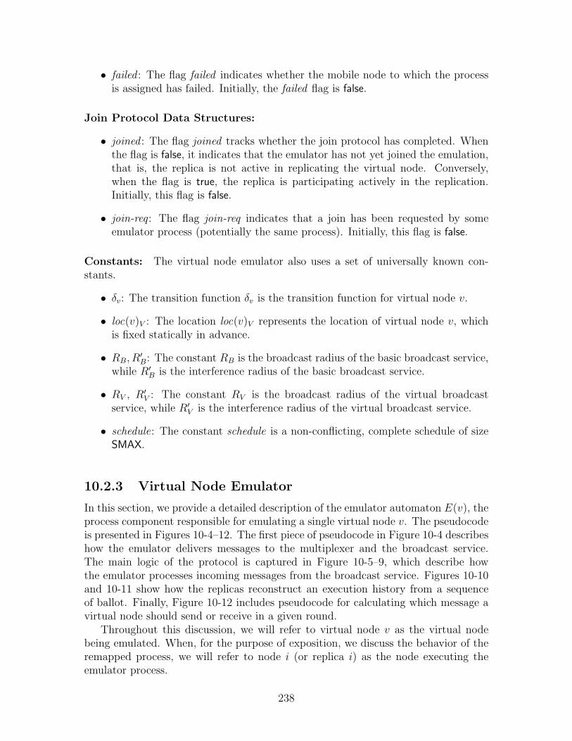
• failed : The flag failed indicates whether the mobile node to which the processis assigned has failed. Initially, the failed flag is false.
Join Protocol Data Structures:
• joined : The flag joined tracks whether the join protocol has completed. Whenthe flag is false, it indicates that the emulator has not yet joined the emulation,that is, the replica is not active in replicating the virtual node. Conversely,when the flag is true, the replica is participating actively in the replication.Initially, this flag is false.
• join-req : The flag join-req indicates that a join has been requested by someemulator process (potentially the same process). Initially, this flag is false.
Constants: The virtual node emulator also uses a set of universally known con-stants.
• δv: The transition function δv is the transition function for virtual node v.
• loc(v)V : The location loc(v)V represents the location of virtual node v, whichis fixed statically in advance.
• RB, R′B: The constant RB is the broadcast radius of the basic broadcast service,while R′B is the interference radius of the basic broadcast service.
• RV , R′V : The constant RV is the broadcast radius of the virtual broadcastservice, while R′V is the interference radius of the virtual broadcast service.
• schedule: The constant schedule is a non-conflicting, complete schedule of sizeSMAX.
10.2.3 Virtual Node Emulator
In this section, we provide a detailed description of the emulator automaton E(v), theprocess component responsible for emulating a single virtual node v. The pseudocodeis presented in Figures 10-4–12. The first piece of pseudocode in Figure 10-4 describeshow the emulator delivers messages to the multiplexer and the broadcast service.The main logic of the protocol is captured in Figure 10-5–9, which describe howthe emulator processes incoming messages from the broadcast service. Figures 10-10and 10-11 show how the replicas reconstruct an execution history from a sequenceof ballot. Finally, Figure 10-12 includes pseudocode for calculating which message avirtual node should send or receive in a given round.
Throughout this discussion, we will refer to virtual node v as the virtual nodebeing emulated. When, for the purpose of exposition, we discuss the behavior of theremapped process, we will refer to node i (or replica i) as the node executing theemulator process.
238

Figure 10-4: Automaton E(v): Virtual Node Emulator 1 —Delivering Messages to the Network / Client
158 Output bcast(m, cm)v
159 Precondition:160 failed = false161 do-net-bcast = true162 do-client-recv = false163 m = outgoing-msg164 if (joined = true) then165 cm = v166 else167 cm = ⊥168 Effect:169 outgoing-msg ← ⊥170 phase ← phase +1171 do-net-bcast ← false172
173 Output vn-client-output(vnm-out, vnCD-out)v
174 Precondition:175 failed = false176 do-client-recv = true177 if (round-status[rnd ] = green) then178 if (v ∈ schedule[rnd mod SMAX ]) then179 if (∃ 〈vn, v, m〉 ∈ ballot[rnd ].vnM : m ∈ msgsV ) then180 Choose 〈vn, v, m〉 ∈ ballot[rnd ].vnM181 vnm-out = 〈vn, m, loc(v)V 〉182 vnCD-out = null183 else if (vnphaseBcast = true) then184 vnm-out = ⊥185 vnCD-out = ±186 else187 vnm-out = ⊥188 vnCD-out = null189 else if (v /∈ schedule[rnd mod SMAX ]) then190 if (vnphaseBcast = true) then191 vnm-out = ⊥192 vnCD-out = ±193 else if (round-status[rnd-1 ] ∈ {green, ⊥}) then194 vnm-out = ⊥195 vnCD-out = null196 else if (ballot[rnd ].vnCD = ±) or (vnCD = ±)then197 vnm-out = ⊥198 vnCD-out = ±199 else200 vnm-out = ⊥201 vnCD-out = null202 else if (round-status[rnd ] = ⊥) then203 vnm-out = ⊥204 vnCD-out = null205 else206 vnm-out = ⊥207 vnCD-out = ±208 Effect:209 do-client-recv ← false210
211 Input fail212 Effect:213 failed ← true214 scheduled ← false
239
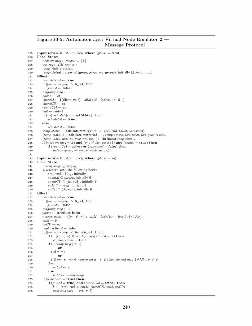
Figure 10-5: Automaton E(v): Virtual Node Emulator 2 —Message Protocol
215 Input recv(allM, cd, cm, loc)v where (phase = client)216 Local State:217 next-vn-msg ∈ msgsV ∪ {⊥}218 out-req ∈ CM-namesV
219 temp-state ∈ statesv220 temp-status[ ], array of 〈green, yellow, orange, red〉, initially [⊥, bot, . . . ,⊥]221 Effect:222 do-net-bcast ← true223 if (|loc − loc(v)V | > RB/4) then224 joined ← false225 outgoing-msg ← ⊥226 phase ← vn227 clientM ← {〈client, m, `〉∈ allM : |`− loc(v)V | ≤ RV }228 clientCD ← cd229 roundCM ← cm230 rnd ← rnd+1231 if (v ∈ schedule[rnd mod SMAX ]) then232 scheduled ← true233 else234 scheduled ← false235 temp-status ← calculate-status(rnd− 1, prev-rnd, ballot, last-reset)236 〈temp-state, ·〉← calculate-state(rnd− 1, temp-status, last-reset, last-good-state)v
237 〈temp-state, next-vn-msg, out-req, ·〉← do-bcast(temp-state)v
238 if (next-vn-msg 6= ⊥) and (rnd 6= last-reset+1) and (joined = true) then239 if (roundCM = active) or (scheduled = false) then240 outgoing-msg ← 〈vn, v, next-vn-msg〉241
242 Input recv(allM, cd, cm, loc)v where (phase = vn)243 Local State:244 nearby-msgs ⊆ msgsB
245 b, a record with the following fields:246 prev-rnd ∈ N0⊥, initially ⊥247 clientM ⊆ msgsB , initially ∅248 clientCD ⊆ {±, null}, initially ∅249 vnM ⊆ msgsB , initially ∅250 vnCD ⊆ {±, null}, initially ∅251 Effect:252 do-net-bcast ← true253 if (|loc − loc(v)V | > RB/4) then254 joined ← false255 outgoing-msg ← ⊥256 phase ← scheduled-ballot257 nearby-msgs ← {〈vn, v′, m〉 ∈ allM : |loc(v′)V − loc(v)V | ≤ RV }258 vnM ← ∅259 vnCD ← null260 vnphaseBcast ← false261 if (|loc − loc(v)V | < RV +RB/4) then262 if (∃ 〈vn, v, m〉 ∈ nearby-msgs) or (cd = ±) then263 vnphaseBcast ← true264 if (|nearby-msgs| > 1)265 or266 (cd = ±)267 or268 ((∃ 〈vn, v′, m〉 ∈ nearby-msgs : v′ /∈ schedule[rnd mod SMAX ], v′ 6= v)269 then270 vnCD ← ±271 else272 vnM ← nearby-msgs273 if (scheduled = true) then274 if (joined = true) and (roundCM = active) then275 b ← 〈prev-rnd, clientM, clientCD, vnM, vnCD〉276 outgoing-msg ← 〈vn, v, b〉
240

Figure 10-6: Automaton E(v): Virtual Node Emulator 3 —Scheduled Agreement Instance
277 Input recv(allM, cd, cm, loc)v where (phase = scheduled-ballot)278 Local State:279 M ⊆ msgsB
280 my-ballots ⊆ msgsB
281 all-ballots ⊆ msgsB
282 ballot-msgs ⊆ msgsB
283 nearby-vn-msgs ⊆ msgsB
284 nearby-msgs ⊆ msgsB
285 near-scheduledV ⊆ IV
286 Effect:287 do-net-bcast ← true288 if (|loc − loc(v)V | > RB/4) then289 joined ← false290 outgoing-msg ← ⊥291 phase ← scheduled-veto-1292 my-ballots ← {b : 〈vn, v, b〉 ∈ allM}293 all-ballots ← {b : v′ ∈ IV , 〈vn, v′, b〉 ∈ allM}294 ballot-msgs ← {〈vn, v′, m〉 ∈ b.vnM : v′ ∈ IV , b ∈ all-ballots}295 nearby-vn-msgs ←296 {〈vn, v′, m〉 ∈ ballot-msgs : |loc(v′)V − loc(v)V | ≤ RV }297 nearby-msgs ←298 {〈vn, v′, m〉 ∈ nearby-vn-msgs : |loc(v′)V − loc| ≤ RV +RB/4}299 vnM ← vnM ∩ nearby-msgs300 near-scheduledV ← {v′ ∈ IV :301 (1) v′ is scheduled,302 (2) |loc− loc(v′)V | ≤ RV + RB/4}303 scheduled-status ← ⊥304 if (|loc − loc(v)V | > RV +RB/4) then305 vnM ← ∅306 else (near-scheduledV = ∅) then307 vnM ← ∅308 else choose unique v′ ∈ near-scheduledV :309 if (cd = ±)310 or311 (|{b : 〈vn, v′, b〉 ∈ allM| > 1)312 then313 scheduled-status ← red314 vnM ← ∅315 if (v = v′) and (scheduled = true) and (joined = true) then316 if (∃ b ∈ my-ballots) then317 ballot[rnd ] ← b ∈ my-ballots318 else319 scheduled-status ← red320 if (scheduled-status 6= ⊥) then321 outgoing-msg ← 〈vn, v, veto〉
241

Figure 10-7: Automaton E(v): Virtual Node Emulator 3 —Scheduled Agreement Instance
322 Input recv(allM, cd, cm, loc)v where (phase = scheduled-veto-1)323 Effect:324 do-net-bcast ← true325 if (|loc − loc(v)V | > RB/4) then326 joined ← false327 outgoing-msg ← ⊥328 phase ← scheduled-veto-2329 vnM ← vnM −330 {〈vn, v′, m〉 ∈ vnM : v′ ∈ IV , |loc − loc(v′)V | > RV +RB/4}331 if (|loc − loc(v)V | > RV +RB/4) then332 vnM ← ∅333 ballot[rnd ] ← 〈⊥, ∅, ∅, ∅, ∅〉334 if (〈vn, v′, veto〉 ∈ allM) or (cd = ±) then335 if (scheduled-status 6= red) then336 scheduled-status ← orange337 if (scheduled-status ∈ {red,orange})338 and339 (joined = true)340 and341 (scheduled = true) then342 outgoing-msg ← 〈vn, v, veto〉343
344 Input recv(allM, cd, cm, loc)v where (phase = scheduled-veto-2)345 Effect:346 do-net-bcast ← true347 if (|loc − loc(v)V | > RB/4) then348 joined ← false349 outgoing-msg ← ⊥350 phase ← unscheduled-ballot351 vnM ← vnM −352 {〈vn, v′, m〉 ∈ vnM : v′ ∈ IV , |loc − loc(v′)V | > RV +RB/4}353 if (|loc − loc(v)V | > RV +RB/4) then354 vnM ← ∅355 if (〈vn, v, veto〉 ∈ allM) or (cd = ±) then356 if (scheduled-status /∈ {orange, red}) then357 scheduled-status ← yellow358 if (scheduled = true) then359 if (scheduled-status = ⊥) and (|loc − loc(v)V | ≤ RV ) then360 round-status[rnd ] ← green361 else362 round-status[rnd ] ← scheduled-status363 if (round-status[rnd ] ∈ {yellow, green}) then364 if (joined = true) then365 prev-rnd ← rnd366 else if (scheduled-status 6= ⊥) then367 vnM ← ∅368 vnCD ← ±369 unscheduled-ballot-rnd ← 0
242
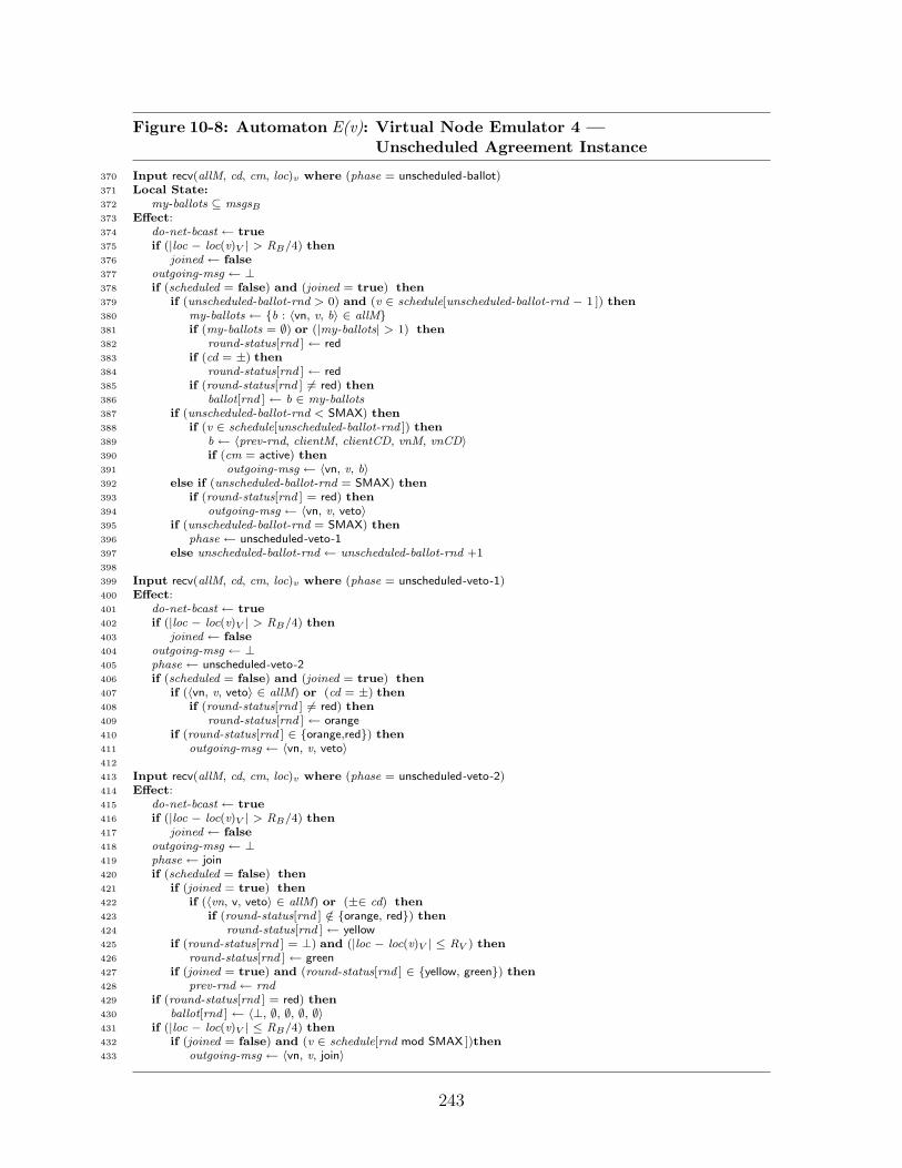
Figure 10-8: Automaton E(v): Virtual Node Emulator 4 —Unscheduled Agreement Instance
370 Input recv(allM, cd, cm, loc)v where (phase = unscheduled-ballot)371 Local State:372 my-ballots ⊆ msgsB
373 Effect:374 do-net-bcast ← true375 if (|loc − loc(v)V | > RB/4) then376 joined ← false377 outgoing-msg ← ⊥378 if (scheduled = false) and (joined = true) then379 if (unscheduled-ballot-rnd > 0) and (v ∈ schedule[unscheduled-ballot-rnd − 1 ]) then380 my-ballots ← {b : 〈vn, v, b〉 ∈ allM}381 if (my-ballots = ∅) or (|my-ballots| > 1) then382 round-status[rnd ] ← red383 if (cd = ±) then384 round-status[rnd ] ← red385 if (round-status[rnd ] 6= red) then386 ballot[rnd ] ← b ∈ my-ballots387 if (unscheduled-ballot-rnd < SMAX) then388 if (v ∈ schedule[unscheduled-ballot-rnd ]) then389 b ← 〈prev-rnd, clientM, clientCD, vnM, vnCD〉390 if (cm = active) then391 outgoing-msg ← 〈vn, v, b〉392 else if (unscheduled-ballot-rnd = SMAX) then393 if (round-status[rnd ] = red) then394 outgoing-msg ← 〈vn, v, veto〉395 if (unscheduled-ballot-rnd = SMAX) then396 phase ← unscheduled-veto-1397 else unscheduled-ballot-rnd ← unscheduled-ballot-rnd +1398
399 Input recv(allM, cd, cm, loc)v where (phase = unscheduled-veto-1)400 Effect:401 do-net-bcast ← true402 if (|loc − loc(v)V | > RB/4) then403 joined ← false404 outgoing-msg ← ⊥405 phase ← unscheduled-veto-2406 if (scheduled = false) and (joined = true) then407 if (〈vn, v, veto〉 ∈ allM) or (cd = ±) then408 if (round-status[rnd ] 6= red) then409 round-status[rnd ] ← orange410 if (round-status[rnd ] ∈ {orange,red}) then411 outgoing-msg ← 〈vn, v, veto〉412
413 Input recv(allM, cd, cm, loc)v where (phase = unscheduled-veto-2)414 Effect:415 do-net-bcast ← true416 if (|loc − loc(v)V | > RB/4) then417 joined ← false418 outgoing-msg ← ⊥419 phase ← join420 if (scheduled = false) then421 if (joined = true) then422 if (〈vn, v, veto〉 ∈ allM) or (±∈ cd) then423 if (round-status[rnd ] /∈ {orange, red}) then424 round-status[rnd ] ← yellow425 if (round-status[rnd ] = ⊥) and (|loc − loc(v)V | ≤ RV ) then426 round-status[rnd ] ← green427 if (joined = true) and (round-status[rnd ] ∈ {yellow, green}) then428 prev-rnd ← rnd429 if (round-status[rnd ] = red) then430 ballot[rnd ] ← 〈⊥, ∅, ∅, ∅, ∅〉431 if (|loc − loc(v)V | ≤ RB/4) then432 if (joined = false) and (v ∈ schedule[rnd mod SMAX ])then433 outgoing-msg ← 〈vn, v, join〉
243

Figure 10-9: Automaton E(v): Virtual Node Emulator 5 — Join Protocol
434 Input recv(allM, cd, cm, loc)v where (phase = join)435 Effect:436 do-net-bcast ← true437 if (|loc − loc(v)V | > RB/4) then438 joined ← false439 outgoing-msg ← ⊥440 phase ← join-ack441 join-req ← false442 if (v ∈ schedule[rnd mod SMAX ]) then443 if (allM 6= ∅) or (cd = ±)then444 join-req ← true445 if (joined = true) and (cm = active) then446 outgoing-msg ← 〈join, v, 〈ballot, round-status, prev-rnd, vnphaseBcast, last-good-state, last-reset〉 〉447
448 Input recv(allM, cd, cm, loc)v where (phase = join-ack)449 Local State:450 join-msgs ⊆ msgsB
451 Effect:452 do-net-bcast ← true453 if (|loc − loc(v)V | > RB/4) then454 joined ← false455 outgoing-msg ← ⊥456 phase ← join-veto457 join-msgs ← {m : 〈join, v, m〉 ∈ allM}458 if (|loc − loc(v)V | ≤ RB/4) then459 if (joined = false) then460 if (join-msgs 6= ∅) then461 Choose m ∈ join-msgs.462 〈ballot, round-status, prev-rnd, vnphaseBcast, last-good-state, last-reset〉 ← m463 joined ← true464 else if (cd = ±)then465 outgoing-msg ← 〈vn, v, veto〉466 reset ← false467 if (v ∈ schedule[rnd mod SMAX ] then468 if (joined = true) then469 outgoing-msg ← 〈vn, v, veto〉470 else if (|loc − loc(v)V | ≤ RB/4) then471 reset ← true472
473 Input recv(allM, cd, cm, loc)v where (phase = join-veto)474 Effect:475 do-net-bcast ← true476 if (|loc − loc(v)V | > RB/4) then477 joined ← false478 outgoing-msg ← ⊥479 phase ← client480 if (|loc − loc(v)V | ≤ RB/4) and (v ∈ schedule[rnd mod SMAX ]) and (reset = true) then481 if (joined = false) and (〈vn, v, veto〉 /∈ allM) and (cd 6= ±)then482 joined ← true483 join-req ← false484 last-good-state ← startv , the initial state of virtual node v485 last-reset ← rnd486 prev-rnd ← rnd487 for all r ≤ rnd: ballot[r ] ← 〈⊥, ∅, ∅, ∅〉488 for all r ≤ rnd: round-status[r ] ← ⊥489 do-client-recv ← true
244
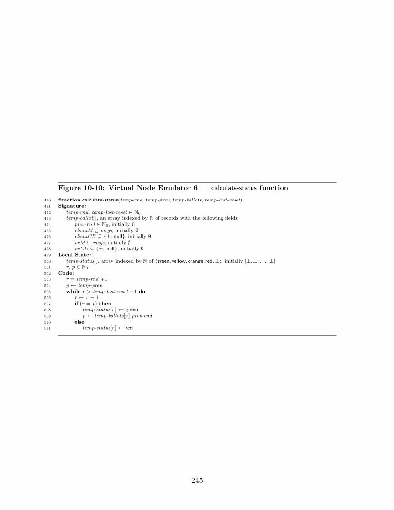
Figure 10-10: Virtual Node Emulator 6 — calculate-status function
490 function calculate-status(temp-rnd, temp-prev, temp-ballots, temp-last-reset)491 Signature:492 temp-rnd, temp-last-reset ∈ N0
493 temp-ballot[ ], an array indexed by N of records with the following fields:494 prev-rnd ∈ N0, initially 0495 clientM ⊆ msgs, initially ∅496 clientCD ⊆ {±, null}, initially ∅497 vnM ⊆ msgs, initially ∅498 vnCD ⊆ {±, null}, initially ∅499 Local State:500 temp-status[ ], array indexed by N of 〈green, yellow, orange, red,⊥〉, initially [⊥,⊥, . . . ,⊥]501 r, p ∈ N0
502 Code:503 r = temp-rnd +1504 p ← temp-prev505 while r > temp-last-reset +1 do506 r ← r − 1507 if (r = p) then508 temp-status[r ] ← green509 p ← temp-ballots[p ].prev-rnd510 else511 temp-status[r ] ← red
245

Figure 10-11: Virtual Node Emulator 7 — calculate-state function
512 function calculate-state(temp-rnd, temp-status, temp-ballot, temp-last-reset, temp-state)v
513 Signature:514 temp-rnd, temp-last-reset ∈ N0
515 temp-status[ ], array indexec by N of 〈green, yellow, orange, red,⊥〉516 temp-ballot[ ], an array indexed by N of records with the following fields:517 prev-rnd ∈ N0, initially 0518 clientM ⊆ msgs, initially ∅519 clientCD ⊆ {±, null}, initially ∅520 vnM ⊆ msgs, initially ∅521 vnCD ⊆ {±, null}, initially ∅522 temp-state ∈ states523 Local State:524 i ∈ N0
525 temp-msg ∈ msgsV
526 inCD ∈ {±, null}527 inCM ∈ {active, passive}528 exec, execution, initially empty529 e-frag-bc, execution, initially empty530 e-frag-rcv, execution, initially empty531 Constants:532 δv , transition function for virtual node v533 loc(v′) ∈ R× R, ∀v′ ∈ V, location of virtual node v′
534 Rv ∈ R, broadcast radius for virtual node v535 schedule[1..SMAX ], schedule array, where schedule[r ] ⊆ V and536 (1) ∀r ∈ [0..SMAX-1 ], ∀v,w ∈ schedule[r ], |loc[v ] -loc[w ]| ≥ 2R′
537 (2) ∀v ∈ V, ∃ r ∈ [0..SMAX-1 ] such that v ∈ schedule[r ]538 Code:539 exec ← τ0, a point trajectory540 for r = temp-last-reset +1 to temp-rnd do541 if (v ∈ schedule[r +1 mod SMAX ]) then542 inCM ← active543 else544 inCM ← passive545 if (temp-status[r ] = green) then546 if (temp-ballot[r ].clientCD = ±) or (temp-ballot[r ].vnCD = ±) then547 inCD ← ±548 else549 inCD ← null550 inM ← {m : 〈client, m, ·〉∈ temp-ballot[r ].clientM} ∪ {m : 〈vn, v′, m〉 ∈ temp-ballot[r ].vnM, v′ 6= v}551 if (r = temp-last-reset+1) then552 e-frag-bc ← ⊥553 else554 〈temp-state, temp-msg, ·, e-frag-bc〉 ← do-bcast(temp-state)v
555 inM ← inM ∪ {temp-msg}556 〈temp-state, e-frag-rcv〉 ← do-recv(temp-state, inM, inCD, inCM)v
557 exec ← exec . e-frag-bc . e-frag-rcv558 else if (temp-status[r ] = red) then559 inM ← ∅560 inCD ← ±561 if (r = temp-last-reset+1) then562 e-frag-bc ← ⊥563 else564 〈temp-state, temp-msg, ·, e-frag-bc〉 ← do-bcast(temp-state)v
565 inM ← inM ∪ {temp-msg}566 〈temp-state, e-frag-rcv〉 ← do-recv(temp-state, {temp-msg}, ±, inCM)v
567 exec ← exec . e-frag-bc . e-frag-rcv568 return 〈temp-state, exec〉
246

Figure 10-12: Virtual Node Emulator 8 — do-bcast and do-recv functions
569 do-bcast(temp-state)v
570 Signature:571 temp-state ∈ states572 Local State:573 next-vn-msg ∈ msgs574 out-req ∈ {active, passive}575 a ∈ internal576 s′ ∈ states577 exec, a timed execution, initially empty578 Constants:579 δv , transition function for virtual node v580 loc(v′) ∈ R× R, ∀v′ ∈ V, location of virtual node v′
581 Code:582 while 6 ∃ s′ ∈ states, nxt-msg ∈ msgs⊥, req ∈ CM-names⊥ s.t. 〈tmp-state, bcast(nxt-msg, req)v,∗, s′〉 ∈ δvdo583 Choose a ∈ internal and s′ ∈ states (deterministically) such that: 〈tmp-state, a, s′〉 ∈ δv
584 exec ← exec . 〈tmp-state, a, s′〉585 tmp-state ← s′
586 Choose nxt-msg ∈M⊥, req ∈ CM-names⊥, s′ ∈ states such that:587 〈tmp-state, bcast(nxt-msg, req)v,∗, s′〉 ∈ δv
588 exec ← exec . 〈tmp-state, bcast(nxt-msg, req)v,∗, s′〉589 tmp-state ← s′
590 return 〈tmp-state, nxt-msg, req, exec〉591
592 do-recv(temp-state, M, cd, cm)v
593 Signature:594 temp-state ∈ states595 M ⊆ msgs596 cd ∈ {±, null}597 cm ∈ {active, passive}598 Local State:599 a ∈ internal600 s′ ∈ states601 timepassage ∈ R602 t ∈ R603 exec, a timed execution, an initially empty604 Constants:605 δv , transition function for virtual node v606 loc(v′) ∈ R× R, ∀v′ ∈ V, location of virtual node v′
607 Code:608 timepassage ← RndLengthV
609 Choose t ≤ timepassage to be the maximum value such that in state temp-state time passage t is enabled.610 while timepassage > 0 do611 while (t = 0) do612 Choose a ∈ internal and s′ ∈ states (deterministically) such that: 〈temp-state, a, s′〉 ∈ δv
613 exec ← exec . 〈temp-state, a, s′〉614 temp-state ← s′
615 Choose t ≤ timepassage to be the maximum value such that in state temp-state time passage t is enabled.616 exec ← exec . τ(t) where τ(t) is a trajectory of length t617 timepassage ← timepassage − t618 Choose s′ ∈ states such that:619 〈temp-state, recv(M, cd, cm, loc[v ])v,∗, s′〉 ∈ δv
620 exec ← exec . 〈temp-state, recv(M, cd, cm, loc[v ])v,∗, s′〉621 temp-state ← s′
622 return 〈temp-state, exec〉
247

Figure 10-13: Multiplexer Automaton
623 State:624 phase ∈ {in, out}, initially out625 rnd ∈ N0, initially 0626 clientBcast ∈ {true, false}, initially false627 inVNs ⊆ V, initially ∅628 inM ⊆ msgsB , initially ∅629 inCD ∈ {±, null}, initially null630 inCM ∈ {active, passive}, initially ⊥631 inLoc ∈ R× R, initially 〈0, 0〉632 bgnRnd ∈ R× R, initially 〈0, 0〉633 outM ⊆ msgsV , initially ∅634 outCM ∈ {global, ⊥}, initially ⊥635 failed ∈ {true, false}, initially false636
637 Signature:638 Input:639 vn-client-output(vnm, vnCD)v , vnm ∈ {〈vn, m, `〉: m ∈ msgsV , `∈ R× R}⊥, vnCD ∈ {±, null}640 bcast(m, cm)∗, m ∈ msgsV , a ∈ CM-namesV ∪ {⊥}641 recv(M, cd, cm, loc)0, M ⊆ msgsB , cd ∈ {±, null}, cm ∈ {active, passive}, loc ∈ R× R642 fail()643
644 Output:645 bcast(m, cm)0, m ∈ msgsB , cm ∈ CM-namesB ∪ {⊥}646 recv(inM, inCD, inCM, inLoc)∗, inM ⊆ msgsV , inCD ∈ {±, null}, inCM ∈ {active, passive}, inLoc ∈ R× R647
648 Transitions:
648 Input vn-client-output(vnm, vnCD)v
649 Effect:650 if (vnm 6= ⊥) and (vnm = 〈vn, ·, ·〉)then651 inM ← inM ∪ {vnm}652 if (±= vnCD) then653 inCD ← ±654 inVNs ← inVNs ∪ v655
656 Output recv(M, inCD, inCM, inLoc)∗657 Local State:658 M-c ⊆ msgsV , initially ∅659 M-vn ⊆ msgsV , initially ∅660 Precondition:661 inVNs = IV
662 phase = out663 rnd mod RndLengthV = 0664 M-c = {m : `∈ R× R, 〈client, m, `〉∈ inM, m 6= ⊥, |`-bgnRnd| ≤ RV }665 M-vn = {m : `∈ R× R, 〈vn, m, `〉∈ inM, m 6= ⊥, |`-bgnRnd| ≤ RV }666 if (inCD = null) then667 M = M-c ∪ M-vn668 else669 M = ∅670 failed = false671 Effect:672 inVNs ← ∅673 inM ← ∅674 bgnRnd ← inLoc675 inLoc ← 0676
677 Input bcast(m, cm)∗678 Effect:679 outM ← m680 outCM ← cm681 clientBcast ← true
682 Output bcast(m, cm)0683 Precondition:684 phase = out685 rnd 6= 0686 if (rnd mod RndLengthV 6= 0)687 then688 m = ⊥689 else690 clientBcast = true691 if (outM = ⊥) then692 m = ⊥693 else694 m = 〈client, outM, bgnRnd〉695 if (outCM = client) then696 cm = global697 else698 cm = ⊥699 failed = false700 Effect:701 phase ← in702 clientBcast ← false703 outM ← ⊥704
705 Input recv(M, cd, cm, loc)0706 Effect:707 if (rnd mod RndLengthV = 0) then708 inM ← inM ∪ {m : 〈client, m, ·〉∈ M}709 inCD ← cd710 inCM ← cm711 inLoc ← loc712 rnd ← rnd+1713 phase ← out714 clientBcast ← false715
716 Input fail()i
717 Effect:718 failed ← true
719 Trajectories:720 stops when:721 phase = out and failed = false
248

Delivering Messages to the Network/Client
Figure 10-4 describes two types of behavior: broadcasting messages to other nodes/pro-cesses, and delivering messages to the client via the multiplexer. It also includes thefail input transition.
The bcast(m, cm)v action (lines 158–171) transmits a previously prepared message.The first two preconditions ensure that the emulator, when composed with a clientprocess, satisfies the dynamic restrictions of a process. Specifically, Restriction 5 of aprocess (Definition 8.1.2) requires that a process perform no external actions after afail input event. The flag failed—see line 160—ensures that the (external) broadcastevent does not occur in this case. Restriction 4 of a process requires that it performa broadcast immediately upon receiving a message, and that broadcasts occur onlyin response to receive events. This is enforced by the do-net-bcast flag, which is setto true only when a message is received (e.g., line 222, Figure 10-5) and reset to falsewhen a broadcast occurs. The next precondition checks the do-client-recv flag; whenthis flag is set to true, a vn-client-recv event can deliver messages to the client.
The remaining preconditions determine which message to transmit, and whetherto contend in the following (basic) round. If some message has been prepared, i.e.,outgoing-msg 6= ⊥, then that message is broadcast. Otherwise, no message is broad-cast, as indicated by the outgoing-msg = ⊥ symbol. Finally, the replica contendsfor contention manager v if it has successfully completed the join protocol, i.e.,joined = true.
The second part of Figure 10-4 is the vn-client-output(vnm-out , vnCD-out)v action(lines 173–209), which delivers messages to the client (via the multiplexer, to bediscussed later). The vn-client-output event occurs at the end of each virtual round,triggering the client to begin the next virtual round.
As usual, the failed flag in the precondition ensures that such events occur onlywhen the process has not failed. The flag do-client-recv plays a similar role as thedo-net-bcast flag: it ensures that the client receives its messages at exactly the correcttime at the end of the virtual round. This flag is set by the last recv in the virtualround (line 489, Figure 10-5), and no further time can pass until the vn-client-outputevent occurs (see Figure 10-2, Trajectories). This flag ensures that the vn-client-outputevent precedes the bcast event at the end of the (virtual) round.
The next set of preconditions (lines 177–207) determines the data to send to theclient. This decision depends on a series of questions: (1) Is round rnd designated asgreen, ⊥, or otherwise? (2) Is v scheduled for virtual round rnd? (3) Does the roundr ballot indicate that v broadcast a message, as determined by the ballot [rnd ].vnMstate variable? (4) Does vnphaseBcast indicate that some node sent a message onbehalf of virtual node v in the vn phase? (5) Is round r − 1 designated as green? (6)Does the round r ballot indicate a collision among virtual nodes, as determined bythe ballot [rnd ].vnCD state variable? These conditions result in a series of cases:
• Round status is green, v is scheduled, and there exists some message in theballot for the current round, i.e., ballot [rnd ].vnM : In this case, the message isdelivered, and no collision is detected. This is the only case in which a messageis delivered to the client, via the multiplexer.
249

• Round status is green, v is scheduled, there is no message specified by the ballot,and the vnphaseBcast flag is set: In this case, no message (⊥) is delivered;however, a collision is detected, as the vnphaseBcast flag is used to indicatethat some message may have been sent, but not received.
• Round status is green, v is scheduled, there is no message specified by the ballot,and the vnphaseBcast flag is not set: In this case, no message (⊥) is delivered,and no collision is detected.
• Round status is green and v is not scheduled: There are four sub-cases. First,if vnphaseBcast = true, then no message is delivered, and a collision is detected.(This is the second of four cases in which a collision is detected.) Second, if thepreceding round rnd − 1 is designated as either green or ⊥, then no message isdelivered and no collision is detected. Third, if either the ballot or the vnCDvariable indicates a collision in the current virtual round, then no message isdelivered and a collision is detected. (This is the third of four cases in whicha collision is detected.) Finally, in all other cases, no message is delivered, andno collision detected.
• Round status is ⊥: In this case, no message is delivered, and no collision isdetected. This case indicates that the current node is not involved with theround emulation.
• Round status is neither green nor ⊥: In this case, no message is delivered, anda collision is detected, as the algorithm can not determine whether a messagewas sent or not. (This is the last of four cases in which a collision is detected.)
The effect of the vn-client-output transition is to reset the do-client-recv flag tofalse, indicating that the event has completed.
The last transition defined in Figure 10-4 is the fail action which sets the flagfailed to true.
Processing Messages
Figures 10-5–10-9 contain the main portion of the protocol, the recv transition def-initions, which processes messages received from the broadcast service. The recvtransition is broken up into cases, one for each phase of the protocol. That is, thechoice of which recv transition to invoke depends on the phase of the protocol, asdetermined by the local state of the emulator. For example, when phase = vn, therecv transition on lines 242–276 (Figure 10-5) is invoked.
There are four main portions to the protocol: the broadcast portion—phases clientand vn (see Figure 10-5), the scheduled agreement portion—phases scheduled-ballot,scheduled-veto-1, scheduled-veto-2 (see Figures 10-6 and 10-7), the unscheduled agree-ment portion—phases unscheduled-ballot, unscheduled-veto-1, unscheduled-veto-2 (seeFigure 10-8), and the join portion—phases join, join-ack, join-veto (see Figure 10-9).
250

The purpose of the broadcast portion of the protocol is to allow the clients an op-portunity to broadcast messages, and to allow the replicas an opportunity to broad-cast messages on behalf of the virtual node. The remainder of the two agreementprotocols is, essentially, agreeing on which of these messages to receive. Notice thatthe clients and replicas broadcast their messages in separate rounds, ensuring non-interference.
The scheduled agreement portion of the protocol is designed to allow the replicasfor “active” virtual nodes to run the agreement protocol, that is, it is designated forreplicas for virtual nodes advised to be active in that virtual round. Since no twonearby virtual nodes are scheduled in the same virtual round, we can conclude thatthere is no interference caused by neighboring virtual nodes during this portion of theprotocol. That is, the replicas for each scheduled virtual node can run the scheduledagreement portion of the protocol free from interference from other replicas for othervirtual nodes.
The unscheduled agreement portion of the protocol is designed to allow the replicasfor “passive” virtual nodes to run the agreement protocol, that is, it is designated forreplicas for virtual nodes advised to be passive during that virtual round. In orderto prevent virtual nodes from interfering with each other during the unscheduledagreement portion, we use the schedule to determine which virtual nodes participatein which (basic) rounds. Thus, the unscheduled agreement portion of the protocolrequires SMAX rounds so that replicas for each virtual node have a chance to broadcasta ballot with no interference.
Both the scheduled and unscheduled instantiations of the agreement protocol im-plement the rules in Figure 10-1. They use the veto phases to ensure that no tworeplicas differ in color by more than one shade.
The three join phases allow a replica to join in the emulation. The replica sendsa join request and receives in response a copy of the replicated state. When there areno other replicas that have already joined, the virtual node can be reset; the last joinphase ensures that the virtual node is reset only when it has previously failed.
We now proceed to describe each recv transition definition—and each of thephases—in more detail. Each recv transition begins with some preliminary stepsthat are common to all of them: first, setting the flag do-net-bcast to true, ensuringthat a response is broadcast immediately; second, checking if the replica is still closeenough to participate in the emulation; third, initializing outgoing-msg to ⊥; fourth,updating the phase flag to the next phase, thus ensuring that in the next (basic)round, the correct recv transition is invoked. (The only exception to this fourth stepis in the unscheduled-ballot phase, where the phase is updated only after SMAX basicrounds.) Each recv transition then continues to implement the specific requirementsof the phase. The last set of steps in a phase are to prepare the message to be sentin the following phase.
Broadcast Phases: (All the line numbers here refer to Figure 10-5.)
• client phase: (lines 215–240) The first phase of the protocol is the clientphase. In the client phase, the clients broadcast their messages. They do
251

this directly (via the multiplexer) and hence the virtual node emulator doesnot broadcast anything in this round. The replica does, however, performsome bookkeeping to prepare for the rest of the virtual round emulation.We begin describing the behavior on line 227 after the shared initial foursteps described above:
– First, the emulator records the messages received from nearby clientsin clientM , and any collision detection information in clientCD . Thisinformation is used throughout the virtual round; a subset of thesemessages is received, conceptually, by the virtual node. (Messagesfrom clients that are far away can be safely discarded.) The emulatoralso saves the contention management information in roundCM . Thiscontention information is used through the remainder of the currentvirtual round.
– Next, the emulator increments the virtual round number rnd (line 230).
– Next, the replica examines the schedule to determine whether its vir-tual node is scheduled in this round; it stores the result of this calcu-lation in the scheduled flag. This flag determines whether the replicaparticipates in the schedule or unscheduled instance of the agreementprotocol.
– Next, the replica determines whether the virtual node being emulatedshould broadcast a message in the current virtual round. Using theemulator variables prev-rnd , ballot , last-reset , and last-good-state, thereplica calculates the current state for the virtual node. Recall that thereplica actually maintains a set of possible executions; the functionscalculate-status and calculate-state determine one preferred execution.(These functions will be discussed in further detail in Section 10.2.4).The replica then calls the do-bcast function, which calculates whether,in the current state, the virtual node should broadcast a message.
– If there is some message to broadcast (next-vn-msg 6= ⊥), and if thevirtual node was not just reset (rnd 6= last-reset+1) , and if the replicahas completed the join protocol (joined = true), then the replica maychoose to broadcast the message in the vn phase which follows (seeline 238). If the replica is emulating a scheduled virtual node, thenit broadcasts the message only if the regional contention manager isadvising the replica itself to be active. Otherwise, if the replica isemulating an unscheduled virtual node, then it broadcasts the messageregardless of the advice of the contention manager. (See line 239.)This may well cause a collision, as the contention manager is beingignored. The message broadcast in this latter case will not be received,regardless: recall that in the vn-client-output transition, a message isdelivered from a virtual node v only if v is scheduled for the round.This is sufficient to guarantee the ECF[GA] property of the virtualbroadcast service.
• vn phase: (lines 242–276) In this phase, the emulator chooses which mes-
252

sages sent by virtual nodes are to be received by the virtual node v in thevirtual round being emulated. Replicas broadcast messages on behalf oftheir virtual nodes in the vn phase. If exactly one neighboring virtual nodeis scheduled and broadcasts a message (via exactly one of its replicas), thenthis message is set to be received by virtual node v; otherwise, virtual nodev is set to detect a collision in the virtual round being emulated. The recvtransition for the vn phase begins with the same four initial steps. it thenproceeds as follows:
– First, the emulator records the incoming messages sent by virtualnodes that are near to virtual node v (nearby-msgs).
– Next, vnM and vnCD are initialized to ∅ and null, respectively. Also,vnphaseBcast is initialized to false.
– Next (line 261), the emulator checks whether the replica is close enoughto v to proceed. If j is within distance RV + RB/4 of loc(v), then theemulator proceeds to calculate the sets vnM andvnCD and the flagvnphaseBcast .
– The emulator then attempts to determine the appropriate value for thevnphaseBcast flag. If there is some message from v in nearby-msgs ,then the flag is set. Alternatively, if cd = ±, i.e., if the emulatordetects a collision, then the flag is set. From the completeness andaccuracy properties of the collision detector we can determine that ifa message is sent in the vn phase by a replica within distance RB, thisflag is set; if, after “stabilization” this flag is set, then some replicawithin distance R′B sent a message.
– The emulator then checks a series of conditions which determine whetherany of the messages from the nearby virtual nodes can be received, andwhether a collision should be detected. If more than one message is re-ceived from a nearby node, or if a collision is detected, or if a messageis received from some unscheduled virtual node (6= v), then a collisionis reported (vnCD ← ±), and no messages are received, i.e. vnM re-mains ∅. Otherwise, vnM is set to nearby-msgs , that is, virtual node vshould receive all the messages sent by nearby nodes. Notice that thisideal situation occurs only when exactly one message is received froma nearby virtual node, that virtual node is scheduled, and no collisionis detected in the vn phase.
– Finally, the emulator assembles the ballot b, and prepares the messageoutgoing-msg for the following phase. A ballot is sent only if virtualnode v is scheduled, only if the emulator has completed the join pro-tocol, and only if the contention manager has advised the emulator tobe active. In this case, outgoing-msg is set to 〈vn, v, b〉, where ballot bconsists of the following components:
∗ prev-rnd , the most recent yellow or green round,
∗ clientM , the set of messages broadcast by clients in the currentvirtual round,
253
∗ clientCD , the collision detection information for the client phase,
∗ vnM , the set of messages broadcast by replicas on behalf of virtualnodes in the current virtual round,
∗ vnCD , the collision detection information for the virtual nodephase,
The result of the ballot will (eventually) be a decision as to whichmessages the virtual node should recv in that virtual round.
Scheduled Agreement Phases: (All the line numbers here refer to Figures 10-6and 10-7.)
• scheduled-ballot phase: (lines 277–321) In this phase, the replica records thecurrent ballot, and begins the process of choosing a color for the currentround. The recv transition begins with the usual four steps, and thenproceeds as follows:
– First (lines 292–293), we consider certain sets of ballots derived fromallM , the set of messages received in the current basic round. The setmy-ballots contains all the ballots broadcast on behalf of virtual nodev. The set all-ballots contains all the ballots broadcast on behalf ofany virtual node. (It is clear that my-ballots ⊆ all-ballots .)
– Next (lines 294–298), we derive from the set of ballots, the sets ofmessages that virtual node v may choose to receive in this virtualround. The set ballot-msgs is the entire set of messages received in anyballot from any virtual node. The set nearby-vn-msgs is the restrictedset of messages sent by a virtual node v′ that is near to v. The setnearby-msgs is the further restricted set of messages sent by a virtualnode v′ that is near to the current location of the replica. As a result,every message in nearby-msgs is (1) included in a ballot in allM , (2)broadcast by a virtual node v′ near to v, and (3) broadcast by a virtualnode v′ near to the location of the replica.
– Recall that previously, in the vn phase, we established a set of mes-sages vnM that the virtual node can receive in the current virtualnode. At this point, we further restrict this set of messages, takingthe intersection of this set with nearby-msgs . Thus, for a virtual nodeto receive a message in a virtual round from another virtual node, theemulator must both receive that message in the vn phase, and alsofind the message in a ballot received during the scheduled-ballot phase.This ensures that the message is part of the proposal received by allthe replicas.
– Next (lines 300–302), we calculate the set of virtual nodes that are nearto v and also scheduled. This is stored in the variable near-scheduledV .
– The scheduled-status is initialized to ⊥. As the round proceeds, thecolor will be further determined; it remains ⊥ at the end of the virtual
254

round only if the emulator is too far away from virtual node v todetermine a color for the round.
– The first case to consider is where the node running the emulator istoo far away from v. In this case, vnM is set to ∅: no messages are tobe received. Notice that scheduled-status remains ⊥.
– The second case to consider is when nearby-scheduledV = ∅, that is,there is no virtual node v′ such that v′ is scheduled and v′ is close tothe node executing the emulator. Notice that if v is scheduled, thenthis case is never reached; this covers the case where v is unscheduled,the node executing the emulator is close enough to v, but there isno scheduled virtual node nearby. In this case too, no message isreceived, i.e., vnM ← ∅. When the vnM variable is next examined inthe unscheduled-ballot phase, the emulator will conclude that there areno messages to be received from a nearby virtual node.
– In the third case, the emulator is near enough to a scheduled virtualnode to potentially receive messages. There is at most one element inthe set nearby-scheduledV , since the schedule is non-conflicting. Wechoose v′ as the unique nearby scheduled virtual node. (Notice that v′
may equal v.) If cd = ±, that is, if the emulator detects a collision inthe scheduled-ballot phase, then the scheduled-status is set to red, theset of messages to receive vnM is emptied, and a collision is set to bedetected by the virtual node (as per vnCD). Similarly, if more thanone ballot is received from v′, the status is set to red, no messagesare received by the virtual node, and a collision is detected. Noticethat if v is unscheduled, this information will next be used in theunscheduled-ballot phase.At this point, we proceed to fix the ballot and, possibly, prepare a vetomessage if the following three conditions hold: v = v′, v is scheduled,and the emulator has completed the join protocol. If there exists aballot b in my-ballots , then that ballot is recorded in the ballot datastructure. If there is no ballot, however, then we designate the roundas red. Next, the replica performs a veto if anything has gone wrong.That is, if the scheduled-status is not ⊥, then it broadcasts a vetomessage in the following phase. Notice that only replicas that havecompleted the join protocol participate in broadcasting veto message.
• scheduled-veto-1 phase: (lines 322–342) In the first veto phase, if the replicareceives a veto message or detects a collision, it downgrades the color ofthe round from green or yellow to orange. (If it is already designated asorange or red, the color remains unchanged, of course.) It then preparesto broadcast a veto, if necessary.
First, (after the usual initial four steps), the replica removes any messagesfrom vnM that are sent by virtual nodes that are (now) too far away. If atany point during the virtual round, the replica exceeds a certain distancefrom virtual node v′, then it should not propose receiving any messages
255

from v′.
Next, the replica checks whether it is near enough to v to continue toparticipate. If not, the set of message vnM is set to ∅, and the ballot iscleared.
Next (line 334) the emulator checks whether it has received a veto messageor detected a collision. If so, then the scheduled-status is downgraded toorange (if it is not already red).
Finally, the emulator prepares to veto in the second veto phase if theround is currently designated as red or orange. This veto ensures that ifthe replica designates the round as orange, then all other replicas designatethe round as at best yellow. The replica vetos only if it has completed thejoin protocol and is representing a virtual node that is scheduled.
• scheduled-veto-2 phase: (lines 344–369) In the second veto phase, if theemulator receives a veto phase or detects a collision, it downgrades thecolor of the round from green to yellow. If it is already yellow or orangeor red, the color is of course left unchanged.
As in the scheduled-veto-1 phase, the recv transition begins (after the usualinitial four steps), by removing any messages from vnM that are sent byvirtual nodes that are (now) too far away, and then by checking whetherit is near enough to v to continue to participate.
Next (line 355) the emulator checks whether it received a veto message ordetects a collision. If so, the scheduled-status is downgraded to yellow, ifit is not already orange or red.
If the replica represents a virtual node that is scheduled, then the colorof the round is now determined, and the replica updates the round-statusarray to reflect this new determination. Specifically, if the scheduled-statusremains unmodified at ⊥, and if the replica is sufficiently close to v, thenthe round-status is set to green. Otherwise, the round-status is updatedto equal the calculated scheduled-status . The emulator then updates theprev-rnd pointer, if the round is green or yellow, and if the replica hascompleted the join protocol. This maintains the invariant that prev-rndrefers to the most recent round locally designated as green or yellow.
If, on the other hand, the replica represents a virtual node that is unsched-uled, then the emulator prepares for the unscheduled agreement portion ofthe protocol. Notice that the replica has observed the scheduled agreementphases, even though it has not participated. Recall that it has updatedscheduled-status , even though it has not performed vetos. If it believes thestatus is green, then is prepares to receive whatever messages were broad-cast during the scheduled portion of the protocol. Otherwise, it throwsaway any messages in vnM , and decides to detect a collision. In moredetail, if the scheduled-status has been downgraded, i.e., is no longer ⊥(line 366), then the emulator determines that it should not receive anymessages from virtual nodes (i.e., vnM ← ∅), and that it should detect acollision (i.e., vnCD ← ±).
256
Finally, it sets unscheduled-ballot-rnd to zero, preparing for the unsched-uled agreement phases.
Unscheduled Agreement Phases: (All the line numbers here refer to Figure 10-8.)
• unscheduled-ballot phase: (lines 370–397) The unscheduled ballot phaselasts for SMAX basic rounds; it is the only phase that takes more than asingle basic round. The code for the unscheduled-ballot phase is dividedinto three parts: first, the node receives and processes messages; then itprepares to broadcast a message in the next (basic) round; finally, it checksif the phase is complete.
As there are SMAX rounds in the unscheduled-ballot phase, the variableunscheduled-ballot-rnd keeps a count of basic rounds that have elapsed dur-ing the phase. The schedule determines which virtual nodes use which basicrounds. If v ∈ schedule[unscheduled-ballot-rnd ], then a replica for v maychoose to broadcast a ballot in the next basic round (if it chooses to broad-cast a ballot). If virtual node v ∈ schedule[unscheduled-ballot-rnd−1], thena replica for v processes a ballot in the current basic round. (Notice, then,that all messages associated with virtual node v are broadcast and receivedin the basic round where v ∈ schedule[unscheduled-ballot-rnd − 1].)
The recv transition begins (after three of the usual four initial steps), bychecking whether virtual node v is scheduled, and whether the replicahas completed the join protocol. As this is the unscheduled instance, theemulator proceeds only if virtual node v is not scheduled. We also proceedonly if the replica has completed the join protocol. (Notice that this isunlike the scheduled agreement portion, in which some preparation mustbe made for the later unscheduled portion, regardless of whether the vis scheduled or unscheduled, and regardless of whether the replica hascompleted the join protocol.) The emulator then proceeds as follows:
– In the first part, a replica processes ballots received in a basic roundwhere virtual node v ∈ schedule[unscheduled-ballot-rnd−1] (see lines 379–386. The emulator begins by checking whether unscheduled-ballot-rnd >0, and then proceeds to determine whether virtual node v is selectedby the schedule, i.e., if
v ∈ schedule[unscheduled-ballot-rnd − 1] ;
this determines whether virtual node v is using this basic round as itsballot round. If so, my-ballots is assigned the set of ballots receivedfor virtual node v in the current round. If my-ballots = ∅, then thereis no ballot, and the round is designated as red. Similarly, if there isa collision (i.e., cd = ±), then the round is designated as red. Finally,if the round is not designated as red, then the ballot is recorded.
257
– In the second part, a replica prepares to broadcast a ballot in thefollowing basic round, under certain circumstances (lines 387–394).The emulator first checks that this is the appropriate basic round, i.e.,unscheduled-ballot-rnd < SMAX and virtual node v is selected by thescheduled:
v ∈ schedule[unscheduled-ballot-rnd ] .
Next, ballot b is formed from the prev-rnd , clientM , vnM , and vnCDvariables. (Notice that the vnM and vnCD variables were prepared inthe vn and scheduled-ballot phases above; the clientM and clientCDvariables were prepared in the client phase.) The ballot is broadcast,then, only if the replica is designated by the contention manager tobe active. (Recall we have already assumed that the replica has com-pleted the join protocol.) In the case where unscheduled-ballot-rnd =SMAX, the replica prepares a message for the following phase, theunscheduled-veto-1 phase. In this case, if the round status has beendowngraded to red, then outgoing-msg is set to 〈vn, v, veto〉, i.e., a vetomessage is prepared.
– In the third part, the phase is updated (lines 395–397). If the phase isnot yet complete, i.e., if unscheduled-ballot-rnd < SMAX, then the ba-sic round count is incremented. Otherwise, if unscheduled-ballot-rnd =SMAX, then the unscheduled-ballot phase is complete, and the phaseis advanced to the unscheduled-veto-1 phase.
• unscheduled-veto-1 phase: (lines 399–411 In the first veto phase, if thereplica receives a veto message or detects a collision, it downgrades thecolor of the round to orange. (If it is already designated as red, it remainsred, of course.)
First (after the usual four steps), the emulator checks that virtual nodev is unscheduled, and that the replica has completed the join protocol.Otherwise, the replica does not participate in this veto phase.
Next, the emulator determines whether a veto message has been received,or a collision detected. If so, the round status is downgraded to orange, ifit is not already red.
Finally, if the round is currently designated as red or orange, the replicaprepares to veto in the second veto phase, thus ensuring that all otherreplicas designate the round as, at best, yellow.
• unscheduled-veto-2 phase: (lines 413–433) In the second veto phase, if theemulator receives a veto message or detects a collision, it downgrades thecolor of the round to yellow. If it is already orange or red, the color is ofcourse left unchanged.
First (after the usual four steps), the emulator checks that virtual node vis unscheduled, and that the replica has completed the join protocol. Inthis case, if the replica receives a veto message, or detects a collision, thenthe round status is downgraded to yellow, if it is not already red or orange.
258

Next (and even if the replica has not completed the join protocol), theround status is finally determined: if the round-status [rnd ] remains ⊥,meaning that it has not been downgraded, and if the replica is close enoughto v, then the round status is designated as green.
In all cases, the color of the round is now determined. Therefore, thereplica updates the prev-rnd pointer: if the round is green or yellow, thereplica stores the current round in prev-rnd . This maintains the invariantthat prev-rnd designates the most recent round locally designated to begreen or yellow.
Next, if the round status is red, the ballot is emptied. Since the round isred, we cannot rely on any information received in the ballot.
The final part of the unscheduled-veto-2 phase prepares the message for thejoin phase. Specifically, the mobile node broadcasts a join request underthe following conditions: (1) the mobile node hosting the replica process iswithin distance RB/4 of the virtual node, (2) the replica has not completedthe join protocol, i.e., joined = false, and (3) virtual node v is scheduledfor the current virtual round, i.e., v ∈ schedule[rnd mod SMAX].
Join Phases: (All the following line numbers here refer to Figure 10-9.)
• join phase: (lines 434–446) In the join phase, a node that has not yetcompleted the joined protocol may broadcast a join request. This joinrequest is received and processed by nodes that have already joined, andthese nodes then send a join response.
First (after the usual four steps), join-req is initialized to false. Under thefollowing circumstances, it is set to true: (1) Virtual node v is scheduledfor the current virtual round; this ensures that any join request comes froma replica for virtual node v. (2) Either allM 6= ∅, indicating some replicasent a join request, or cd = ±, indicating that either some replica senta join request or the collision detector returned a false positive. Thus, ifsome replica for virtual node v broadcast a join request, join-req is set totrue.
Under these circumstances, since there is a join request, the replica sends ajoin response in the next phase if it has, itself, completed the join protocol,and if cm = true, indicating that the current replica has been designatedactive for this basic round.
The resulting join response includes all the state associated with the replica.Specifically, notice that all the input parameters to calculate-status andcalculate-state are included in the join response, with the exception of rnd(which each replica can calculate on its own).
• join-ack phase: (lines 448–471) In this phase, nodes sent responses to thejoin requests. These responses are received by the unjoined nodes, whichprocess these responses and join the emulation.
259

The set join-msgs represents the set of join responses for virtual node v.After the usual initial four steps, this set is derived from allM , the set ofmessages received in the join-ack phase. If the replica is within distanceRB/4 of virtual node v, and has not yet completed the join protocol, and ifit has received a join response, then it adopts the replica state from the joinresponse. If the set of join-msgs is empty, but cd = ±, then some replicaattempted (unsuccessfully) to send a join response; the replica broadcastsa veto in the following join-veto phase, preventing the virtual node frombeing accidently reset.
Finally, the replica prepares for the join-veto phase. It begins by initializereset to false. If v is scheduled for the current virtual round and if thereplica has completed the join protocol, then it broadcasts a veto in thefollowing join-veto phase, thus ensuring that the virtual node is not acci-dently reset. Alternatively, if the replica has not successfully completedthe join protocol, and yet is still close to virtual node v, then it indicatesthat a reset is desirable, setting reset to true.
• join-veto phase: (lines 473–489) If there is no veto in the join-veto phase,then a joining replica knows that no other replica has completed the joinprotocol, and thus the virtual node must be reset. After the usual initialfour steps, the emulator determines whether a reset is appropriate, exam-ining the following conditions: (1) the replica is within distance RB/4 ofthe virtual node v, (2) virtual node v is scheduled for the current virtualround, (3) the reset flag is set to true, indicating that a reset is desirable,(4) the replica has not yet itself completed the join protocol, (5) the replicadoes not receive a veto message, and (6) the replica does not detect a col-lision. The last two conditions ensure that no other replica broadcast aveto message.
Notice that a reset occurs only if v is scheduled; this is because it is only invirtual rounds where v is scheduled that the join protocol for v is invoked;hence we can determine that the join protocol has failed only in suchrounds. Also, notice that the reset flag is used to determine whether areset is desirable. The reset flag is set in the join-ack phase when a join isunsuccessful.
When a reset has occurred, the replica sets its joined flag to true, thejoin-req flag to false, and resets its replica state as per lines 482–488.
Finally, the replica ensures that messages are delivered to the client at theend of the virtual round by setting the do-client-recv flag, which forces avn-client-output to occur immediately afterwards (as per the Trajectoriesin Figure 10-2).
10.2.4 Virtual Node Emulator Helper Functions
In this section we discuss the helper functions used by the virtual node emulator toconstruct an execution of the virtual node.
260

Calculating the Round Status
The calculate-status helper function in Figure 10-10 calculates the status of each round.It takes as input the following parameters:
• temp-rnd , the current virtual round number,
• temp-prev , a copy of prev-rnd , the most recent round locally designated asyellow or green,
• temp-ballot , a copy of the ballot array,
• temp-last-reset , a copy of last-reset , the most recent green round.
The goal of this helper function is to decide which virtual rounds to accept and whichto reject. When a virtual round is accepted, the virtual node receives the messagesdesignated by the ballot in that round. When a virtual round is rejected, the virtualnode detects a collision, regardless of the information in the ballot. Thus, the outputof the calculate-status function is the temp-status array in which each round has beendesignated as either green or red. This status array is then used by the calculate-statefunction to determine the current state of the virtual node.
The status is calculated backward, first starting with the current virtual round,temp-rnd , and counting backwards to temp-last-reset , the most recent time the virtualnode was reset to its initial state. The variable r acts as the loop counter.
In the beginning, the pointer p = temp-prev , the most recent “good” round ≤ r.Thus, all rounds larger than p should be designated as red: as we count backwardsin the array, until we reach round p, each round is designated as red. When we reachround p, we designate that round as green, and update p with the prev-rnd designatedin the ballot from round r. We will show that when this happens, the ballot fromround r always contains a valid entry.
We will show in Corollary 11.6.7 that if two replicas share the same prev-rnd , thenthe calculate-status helper function will calculate the same status for each round. Thusin any green round, every replica will designate the round as green or yellow, resultingin all the replicas agreeing on the prev-rnd , and as a result agreeing on the status ofall prior rounds.
Calculating the Replicated State
The calculate-state helper function in Figure 10-11 calculates the current state of thevirtual node. It reconstructs one plausible execution of the virtual node, based onthe following parameters:
• temp-rnd , a copy of rnd , the current round of the virtual node,
• temp-status , an array indicating which rounds have been accepted and whichrejected; this array is the result of the calculate-status helper function,
• temp-ballot , a copy of the ballot array,
261

• temp-last-reset , a copy of last-reset , the most recent round in which v was reset,
• temp-state, a copy of last-good-state, the state of the replica at the end oftemp-last-reset .
The calculate-state function starts at the round following last-reset , and incrementallycalculates the state of the virtual node. The variable r represents the virtual roundbeing considered, and hence is iterated from temp-last-reset + 1 to temp-rnd . Thefunction proceeds as follows:
• First, it calculates the contention management advice to provide to the virtualnode: if v ∈ schedule[r mod SMAX], then v is advised to be active; otherwise,v is advised to be passive. This information is stored in inCM .
• Next, it breaks into two cases, depending on whether the virtual round is ac-cepted or rejected, that is, whether the calculate-status function designated thisround as green or red.
Green/Accept:First, it determines whether the virtual node should detect a collision basedon the information in the ballot. This information is stored in inCD . Next,it calculates the set of messages the virtual node should receive, based onthe information in the ballot. Specifically, it includes every message fromthe clientM field of the ballot, and every message from the vnM field ofthe ballot except those initiated by virtual node v. Any message fromv itself will be calculated directly, rather than derived from the ballot:the next step proceeds to calculate the message broadcast by v using thedo-bcast function. Notice that if the virtual node was just reset, i.e., ifr = temp-last-reset + 1, then virtual node v does not send any messagesin round r. The message calculated (if any) is added to inM , and theassociated execution fragment is stored in e-frag-bc. Finally, it calls thedo-recv function to simulate the virtual node receiving the specified mes-sages inM , detecting a collision as specified by inCD , receiving contentionmanagement advice as per inCM , and receiving the the (constant) loca-tion. The fragment of the execution in which the virtual node receivesthe message is stored in e-frag-rcv , and hence the entire round executionfragment consisting of e-frag-bc.e-frag-rcv is appended to exec.
Red/Reject:In this case, the replica simulates the virtual node receiving only its ownmessage (if it broadcasts one), detecting a collision, and receiving the cal-culated contention management information and the (constant) location.Thus, the set of message, inM is initially set to be ∅, and inCD is set to ±.As in the previous case, it calculates the message that virtual node v sendsin this case, and adds the message to inM , storing the execution fragmentin e-frag-bc. The receive portion of the execution fragment is calculatedusing the do-recv function, and the execution fragments concatenated toexec. Notice that in this case, no information from the ballot is used.
262

At the end of each iteration, i.e., after completing the calculation for round r, theexecution exec consists of a (timed) execution of the virtual node through the end ofround r. In the end, it returns the final state of the virtual node, and the executionof the virtual node that has been generated. This execution is used primarily in theproof, and is not needed for the algorithm.
Additional Helper Functions:
The remaining helper function in Figure 10-12 are relatively straightforward.
Broadcasting messages. The function do-bcast calculates which message the vir-tual node v sends when it is in the state temp-state. It also calculates the resultingnew state, after the message is broadcast, the resulting contention manager request,and the execution fragment produced by the broadcast event.
The first step in this calculation is to perform any necessary internal actionssuch that a broadcast is enabled. The do-bcast function is called only when the lasttransition of the virtual node was a recv, and hence the properties of a process ensurethat after some set of internal actions a broadcast will be enabled. (See Lemma 10.3.1for a slightly more detailed rendition of this argument.) Next, the function calculatesthe state after the broadcast, and returns the requisite information.
Receiving messages. The function do-recv calculates the state after receiving agiven set of information: a set of messages M , collision detection feedback cd , andcontention manager advice cm. First, it advances time for one virtual RndLengthV
worth of time. The do-recv function is called immediately after a do-bcast, and hencetime must be advanced to the end of the round, before the recv transition shouldoccur. Since all the variables are constant with respect to time passage, it is sufficientto perform whatever internal actions are necessary to allow time to pass. Sincethe process is an internally-progressive TIOA, some set of actions are sufficient toaccomplish this; since the process satisfies the immediate response property, none ofthe actions will be external output actions. (See Lemma 10.3.2 for a slightly moredetailed rendition of this argument.) Finally, it calculates the resulting state, andreturns it. It also returns the execution fragment which includes the time-passageevents, the necessary internal events, and the recv event.
10.2.5 Virtual Node Multiplexer
The virtual node multiplexer, presented in Figure 10-13, is relatively straightforward.Its main purpose is to aggregate messages from the virtual node emulators, as well asthe broadcast service, and deliver them to the client. It also acts as an intermediarybetween the client and the broadcast service, relaying client messages to the broadcastservice.
263

Multiplexer State
The multiplexer contains the following state components:
• phase: specifies whether the multiplexer is relaying information inwards, fromthe broadcast service to the clients, or outwards, from the clients to the broad-cast service. Whenever phase = out, no time is allowed to pass, according to therestriction on trajectories; this indicates that the multiplexer needs to broad-cast a message immediately in order to satisfy the requirement that a processimmediately broadcast a message whenever one is received (Definition 8.1.2).
• rnd : stores the current basic round number, which is incremented every time amessage is received from the broadcast service.
• clientBcast : this flag indicates whether the client has broadcast its message yetfor the current virtual round. The multiplexer cannot re-broadcast the clientmessage until the client has transmitted the message to the multiplexer.
• inVNs : stores the set of virtual nodes that have, so far, delivered informationto the client.
• inM : stores the set of messages to deliver to the client.
• inCD : stores the collision detection information to deliver to the client.
• inCM : stores the contention management information to deliver to the client.
• inLoc: stores the location information to deliver to the client.
• beginRound : stores the location at the beginning of the virtual round.
• outM : stores the messages broadcast by the client.
• outCM : stores the contention management request from the client.
• failed : flag indicating whether the process has failed.
Multiplexer Signature
The multiplexer has the following input and output actions:
• Input vn-client-output(vnm, vnCD)v: receives a message and collision detectionfeedback from the emulator on behalf of virtual node v.
• Input bcast(m, cm)∗: receives the broadcast from the client.
• Input recv(M, cd , cm, loc)0: receives messages from the broadcast service onport 0.
• Input fail: indicates that the process has failed.
• Output bcast(m, cm)0: broadcasts a message using the broadcast service port 0.
• Output recv(m, cd , cm, loc)∗: delivers messages to the client.
264

Multiplexer Transitions
The main functionality of the multiplexer is as follows. Each virtual round consists ofa series of basic rounds. A virtual round begins with a client broadcasting a messageduring the client phase (when rnd mod RndLengthV = 0), in response to the receiveevent from the previous round. The multiplexer receives this bcast∗ event, and relaysthis message to the broadcast service via a bcast0 event. Throughout the rest ofthe phase, the multiplexer simply receives the messages from the broadcast service,and ignores them, broadcasting empty messages in response. Finally, when the lastreceive event in the virtual round occurs, the multiplexer collects messages from thevirtual node emulators, via vn-client-output events, and delivers them to the client,along with any other messages received during the client phase, via a recv∗ event. Inmore detail:
• Input vn-client-output(vnm, vnCD)v: These input events occur during the lastphase of a virtual round. That is, they occur at exactly the end of a virtualround. The multiplexer collects the messages from the various virtual nodesin inM and the collision detection information in inCD . Notice that if anyvirtual node notifies the client of a collision, then inCD ← ±. The multiplexerthen adds virtual node v to the set of virtual nodes inVNs that have deliveredinformation to the client in this virtual round.
• Output recv(M , inCD , inCM , inLoc)∗: These output events deliver informationto the client. They occur at the end of a virtual round. The preconditions ensurethat: (1) every virtual node has delivered information for the current round(inVNs = IV ), (2) the multiplexer is ready to broadcast a message (phase =out), (3) the current basic round is the last phase in the virtual round (rndmod RndLengthV = 0; recall that the first basic round is numbered 1, andhence the last basic round in a virtual round is divisible by RndLengthV ), (4)M-client and M-vn calculate the appropriate messages from the clients andvirtual nodes; only messages sent by nodes that were nearby at the beginning ofthe virtual round are received; messages are delivered only if there is no collisiondetected, and (5) the process has not failed. On delivering the appropriatemessages, collision detection information, contention management information,and location information to the client, each of these variables is reset to the ∅.
• Input bcast(m, cm)∗: These input events are the broadcast events for the clientsfor a given virtual round. They happen immediately after the recv∗ events,and initiate the next virtual round. The message being broadcast is storedin outM , and the contention management request is stored in outCM . Theflag clientBcast is set to true to indicate that the multiplexer is now ready tobroadcast the client’s message.
• Output bcast(m, cm)0: These output events relay the client’s messages to thebroadcast service, during the client phase, and broadcast empty messages inall other phases. The preconditions ensure that the multiplexer is ready tobroadcast the client’s message, if it is the client phase, or an empty message
265

otherwise: First, the multiplexer is ready to broadcast a message (phase = outand rnd 6= 0); recall that a process does not broadcast a message in the firstround. Next, if the current round is a client phase (as determined by examiningthe rnd variable), then the client has broadcast its message (clientBcast = true),and the message is of the form 〈client, m, `〉, where m is the client’s message,and ` is the location of the client when the message was sent at the beginningof the round. (This additional information helps the emulator to process themessage.) Next, The process has not failed (failed = false). After a broadcastevent, the phase is set to in, indicating the multiplexer is now waiting to receivea message. The flag clientBcast is reset, and the message outM is reset to ⊥.
• Input recv(M, cd , cm, loc)0: These input events deliver messages from the broad-cast service to the multiplexer. In the client phase, these messages originate atother clients, and hence are saved, to be delivered to the client at the end ofthe virtual round. Similarly, the collision detection and contention manage-ment information is saved in the client phase. (As the round counter has notyet been incremented, rndmodRndLengthV = 0 in the client phase recv event.)The location inLoc is updated in each round, even after the client phase so thatat the end of the virtual round the client receives the most up-to-date loca-tion estimate. The round counter is then incremented, and the phase is set toout indicating that the multiplexer needs to broadcast a message immediately.Lastly, the clientBcast flag is reset to false.
• Input fail: This input action indicates that the process has failed; therefore thefailed flag is set to true.
10.2.6 Putting the Pieces Together
In this section, we assemble the components previously described, and provide thefull specification for the basic system, that is, fixing the parameters
PB, process-portsB,msgsB, AB,CM-namesB,CM B .
First, we define the emulator automaton E to be the composition of the followingautomata:
{E(v) : v ∈ IV } ∪ {Multiplexer} .
We continue to use the notation E(v), for v ∈ IV , to refer to the emulator automatonfor v in the composition; similarly E(multiplexer) refers to the multiplexer portion ofthe composition.
Next, we define the set of processes, PB. For each client process in the virtualinfrastructure system, we instantiate a new process consisting of the client composedwith the emulator. That is:
PB = {AV (i)× E : i ∈ IB} .
Each process AV (i) is a client process in the virtual infrastructure system, and thus is
266

composed with the emulator automaton E to form a new process in the basic system.We show in Section 10.3 that AV (i)×E is, in fact, a process as per Definition 8.1.2.
Next, we define an algorithm AB which assigns a process to each mobile node.That is, for each i ∈ IB:
AB(i) = AV (i)× E .
Notice that AB is anonymous if AV is anonymous.
We provide each process with one port per virtual node, and one additional port.That is:
process-portsB = IV ∪ {0} .
The set of broadcast ports bcast-portsB = IB×process-portsB, as defined in Chapter 8.
We define one contention manager for each virtual node location, along withone additional “global” contention manager. The contention managers have namesCM-namesB = IV ∪ {global}, and thus
CM B = {CMv : v ∈ IV } ∪ {CMglobal}
We assume that CM v, for v ∈ IV , is an `-regionally fair contention manager forthe port set idbcast− portsB, where ` = loc(v)V . Additionally, we assume that everycontention manager is conservative. We assume that the contention manager CM global
is conservative, but make no further assumptions as to its operation. (In Section 11.10we discuss further the relationship of CM global in the basic system to CM client in thevirtual infrastructure system.)
Finally, we define the set of messages msgsB to be all the possible messages thatthe emulator automaton might send. That is:
• 〈client, m, `〉, ∀m ∈ msgsV , ∀` ∈ R× R,
• 〈vn, v, m〉, ∀m ∈ msgsV , ∀v ∈ IV ,
• 〈vn, v, b〉, for b a ballot, ∀v ∈ IV ,
• 〈vn, v, veto〉, ∀v ∈ IV ,
• 〈vn, v, join〉, ∀v ∈ IV ,
• 〈join, v, 〈b, r, p, f, l, s〉〉, where b is a ballot, r is a round status array, p is a roundnumber, f is a boolean flag, l is a round number, and s is a state of a virtualnode v.
We refer to the virtual infrastructure system defined by this particular set of param-eters:
V S(PB, process-portsB,msgsB, AB,CM-namesB,CM B)
as the emulator system.
267
10.3 Well-Formedness of the Emulator
Before proceeding to discuss the correctness of the emulator system (in Chapter 11),we must first establish that the automata presented in Section 10.2 in fact describes aprocess. Specifically, we show in Theorem 10.3.7 that for all i ∈ IB, if A is a process,then A×E is a process, according to Definition 8.1.2. As a result, the set of processesPB described in Section 10.2.6 is, in fact, a set of processes, and the emulator systemdescribed is reasonable.
In order to verify that automaton A×E is a process, for all processes A, we needto show that E satisfies a set of basic properties. We begin by showing that all thetransitions in E are finite (Lemma 10.3.4). We then show that E is a TIOA, andfinally that A×E is internally progressive. We are then able to show in Theorem 10.3.7that A× E is a process.
We begin by showing that the “functions” described in Figures 10-10–10-12 infact terminate. First, consider the do-bcast function (Figure 10-12). The functiondo-bcast takes one parameter, s, the state of virtual node v. The do-bcast functionterminates when the state represented by s is the last state in an execution fragmentthat concludes with a recv event (with no bcast event that follows it). The argumentdepends on the requirement that a bcast event occur immediately in response to arecv event; hence if the do-bcast function is used to extend an execution of v, it isapplicable only when there is an immediately preceding recv event.
Lemma 10.3.1. Let v ∈ IV be a virtual node and γ an execution of v. Let s =`state(γ) and t = `time(γ). If a recvv,∗ event occurs at time t in γ and no bcastv,∗event occurs at time t in γ after the recv event, then do-bcast(s)v terminates.
Proof. The key requirement is to show that the initial while loop terminates. At thebeginning of the loop the virtual node v is in state s. The loop terminates as soon asthere exists some next-vn-msg ∈ msgs⊥ and out-req ∈ CM-names⊥ such that virtualnode v is enabled in state s to perform a bcast(next-vn-msg , out-req)v,∗ transition.
Assume for the sake of contradiction that do-bcast does not terminate. We claim,then, that the infinite while loop continues to add locally-controlled events to execu-tion fragment exec: Since the automaton at v is a process, and since γ contains a recvevent at time t with no following bcast event, there must be a bcast event prior to anytime-passage event, by Definition 8.1.2. Since the automaton at v is time-passageenabled, and yet time-passage is not enabled since there has been no bcast event,there must be some enabled locally-controlled event. Thus the while loop continuesto add an infinite number of locally-controlled events to the execution γ.exec.
Since the process at v is internally-progressive, we know that only a finite numberof locally-controlled events can occur at time t in any execution γ.exec, assuming onlya finite number of input events occur at time t. Notice, however, that the constructionnever adds an input event to γ.exec. This contradicts our previous statement thatγ.exec contains an infinite number of locally-controlled events at time t, implying thatthe do-bcast function terminates.
Next we show that the do-recv function (Figure 10-12) terminates. Specifically, ifs represents the last state in an execution γ where every recv event has a matching
268

bcast event, then do-recv(s, . . .) terminates. (In fact, we are only interested in bcastand recv events that occur at the last time in γ.) The argument depends primarilyon the fact that a TIOA is time-passage enabled and internally progressive.
Lemma 10.3.2. Let v ∈ IV be a virtual node and γ an execution of v. Let s =`state(γ) and t′ = `time(γ). Assume that every recvv,∗ event at time t′ in γ isfollowed by a bcastv,∗ event at time t′ in γ. Then do-recv(s, . . .)v terminates.
Proof. We argue that the while loop which adds time-passage events terminates.First, notice that it is always possible on line 612 (Figure 10-12) to find an appropriateinternal action a: by the fact that t = 0, we know that time-passage is not enabled;however, the automaton at v is time-passage enabled, implying that some locally-controlled action is enabled; this action cannot be the output action bcast, as a bcastcan happen only in response to a recv event, and we have assumed that every recvevent already has a matching bcast event.
Next, notice that each iteration of the while loop adds a locally-controlled eventto an interval of time no larger than RndLengthV . Since there are only a finite numberof input events during this interval, we know that there are only a finite number ofinternal events, since the automaton at v is internally progressive. Therefore weconclude that the while loop terminates.
We are now able to show that the two calculation functions, calculate-status andcalculate-state, terminate. The argument is a straightforward examination of the loopconstructs used, along with an application of Lemmas 10.3.1 and 10.3.2.
Lemma 10.3.3. The functions calculate-status(. . .) and calculate-state(. . . , temp-state)v
(in Figures 10-10 and 10-11) terminate under the condition that temp-state is the ini-tial state of virtual node v.
Proof. First, it is relatively straightforward to see that the calculate-status terminates:the round counter r is decremented during each iteration of the loop, and henceeventually r ≤ temp-last-reset + 1, at which point the loop terminates.
Second, we examine the calculate-state function. The main loop iterates the roundcounter r from temp-last-reset+1 up to temp-rnd . It remains only to show that its useof do-bcast and do-recv themselves terminate. These two functions are always calledin pairs, thus ensuring that the requisite conditions of Lemmas 10.3.1 and 10.3.2 hold.
In the first iteration of the main while loop, r = temp-last-reset + 1, and henceno broadcast is included in either branch of the if clause. (See lines 551 and 561.)Thus in the first iteration, the functions calls do-recv, where the state temp-state isthe initial state of virtual node v, i.e., the last state in an empty execution exec. Weconclude, then, that the call to do-recv terminates, by Lemma 10.3.2, as there are norecv events in the empty execution exec. After the call to do-recv, and after e-frag-rcvis concatenated to exec, notice that the last event in exec is a recv event; this propertyis maintained throughout the rest of the function execution.
In each later iteration of the main while loop, the calculate-state function invokesboth do-bcast and do-recv. Since temp-state is the last state in exec, and the lastevent in exec is a recvv,∗ event, we can conclude that the do-bcast event terminates
269
by Lemma 10.3.1. At this point, temp-state is the last state of exec.e-frag-bc, and thelast event in e-frag-bc is a bcastv,∗ event. Thus, by Lemma 10.3.2, the do-recv eventterminates. Again, after the call to do-recv and after the execution fragments areconcatenated to exec, the last event in exec is a recv event, maintaining the requisiteproperty.
Thus in each iteration, all the calls to do-bcast and do-recv terminate, and thusthe calculate-state function terminates.
We are now able to show that each transition of the emulator algorithm terminates,that is, that none of the transitions is infinite. The only place where problems mayarise is during the recv transition during the client phase, when the algorithm invokesthe calculate-status, calculate-state, and do-bcast functions. In each case, we showthat the previous lemmas indicate that the function terminates, leading to the desiredconclusion.
Lemma 10.3.4. Each transition in emulator E is finite.
Proof. Since no loop constructs appear in the emulator algorithm, the only potentialproblems arise in the use of the various sub-functions. The calculate-status functionis invoked on line 235, Figure 10-5; by Lemma 10.3.3 we know that it terminates,implying that it is a finite calculation.
Next, consider the calculate-state function that is invoked on line 236, Figure 10-5(in order to calculate the last state of the proposed execution of v). Notice thatthe variable last-good-state is initially the initial state of virtual node v, and isnever changed during an execution of the algorithm. Thus, we can conclude byLemma 10.3.3 that calculate-state terminates, implying that it is a finite calculation.
Finally, notice that the do-bcast function is used in the emulation algorithm online 237, Figure 10-5 (in order to calculate the next message that virtual node vshould send). In this case, temp-state is the state calculated by calculate-state onthe previous line (line 236, Figure 10-5). Recall that calculate-state also returns anexecution which has temp-state as its last state, and which has recvv,∗ as its last action.Thus by Lemma 10.3.1 we conclude that the do-bcast function call terminates.
We can now show that emulator E is, in fact, a TIOA. In particular, this requiresshowing that E is time-passage enabled.
Lemma 10.3.5. Emulator E is a TIOA.
Proof. We have already shown in Lemma 10.3.4 that each transition in E is finite. Weneed to show that E is input enabled and time-passage enabled. The only syntacticrestriction in inputs is the where clauses that restrict the recvv transitions, dependingon the phase. However, for each phase, there is exactly one recv transition enabled.
We now argue that emulator E is time-passage enabled. The trajectories disabletime passage in two circumstances:
• E(v).do-client-recv = true and E(v).failed = false: In this case, under appropri-ate settings of vnm-out and vnCD-out , the vn-client-output(vnm-out , vnCD-out)v
event is enabled. This transition resets E(v).do-client-recv to false.
270

• E(v).do-net-bcast = true and E(v).failed = false: In this case, we can assumethat do-client-recv = false; otherwise, we fall into the previous case. In thiscase, under appropriate settings of m and cm, the bcast(m, cm)v transition isenabled, which resets do-net-bcast to false.
As a result, emulator E is time-passage enabled, and hence E is a TIOA.
The last fact we need to show about the emulator is that, when composed withanother process, i.e., a client, the resulting composed automaton is a process. Weshow this fact in two steps: first we show that the composed automaton is internallyprogressive; then we show that the automaton meets the other requirements of aprocess.
Lemma 10.3.6. If A is a process, then A× E is internally progressive.
Proof. Consider an execution in which each finite interval of time has a finite numberof input actions. We begin by examining the locally-controlled actions of E, andargue that each finite interval has a finite number locally-controlled actions by E.Assume for the sake of contradiction that this is not the case. We consider each ofthe possible locally-controlled actions of E in turn:
• bcastv: Assume there are an infinite number of bcastv events in some finiteinterval of time, for some v ∈ IV . The precondition for the transition is thatdo-net-bcast = true (line 161, Figure 10-4), and in the effect, do-net-bcast isreset to false. Moreover, the only transition which sets do-net-bcast to true isthe recvv input event. Thus, we conclude that for each bcastv event, there isan intervening recvv event that precedes it. This implies that there are alsoan infinite number of recvv input events in the same finite interval of time,contradicting our assumption.
• bcast0: Assume there are an infinite number of bcast0 events in some finiteinterval of time. The argument in terms of bcast0 is almost equivalent, exceptwith respect to the phase flag (rather than the do-net-bcast flag). Specifically,a bcast0 occurs only when phase = out, and its effects reset phase to in. Theonly event that sets phase to out is a recv0 input event. Thus we conclude thatfor each bcast0 event, there is a preceding recv0 event, implying a contradiction.
• vn-client-outputv: Assume there are an infinite number of vn-client-outputv eventsin some finite interval of time, for some v ∈ IV . Again, the argument is almostequivalent, except with respect to the do-client-recv flag. The precondition ofeach vn-client-output transition is that do-client-recv = true, and this flag isreset by the transition’s effects. Moreover, do-client-recv is set to true only bythe recvv input event. Thus we conclude that for each vn-client-outputv event,there is a preceding recvv event, implying a contradiction.
• recv∗: Assume there are an infinite number of recv∗ events in some finite intervalof time. The precondition of the recv∗ event requires that inVNs = V , and theset inVNs is reset to ∅ by the transition’s effects. The only transition which
271

adds v ∈ IV to inVNs is the vn-client-outputv event. Thus, if there are an infinitenumber of recv∗ events in a finite interval of time, there must also be an infinitenumber of vn-client-outputv events for some v ∈ IV , contradicting the previousclaim.
Thus we conclude that if there are a finite number of input events in some finiteinterval, then there are also a finite number of events controlled by automaton E.Finally, we examine automaton A. Since automaton A is a process, we know that itis internally progressive. Since for every finite interval there are a finite number ofevents controlled by E, we can conclude that for A, there are a finite number of inputevents. Thus, we conclude that there are also a finite number of events controlled byA. Overall, then, we conclude that automaton A× E is internally progressive.
Finally, we present the main claim of the section: when emulator E is composedwith a process, the resulting composed automaton is also a process.
Theorem 10.3.7. If A is a process, then A× E is a process.
Proof. First, since A is a TIOA and E is a TIOA (Lemma 10.3.5), we conclude thatA × E is a TIOA. Next, we conclude by Lemma 10.3.6 that A × E is internallyprogressive. It is immediately clear that A × E satisfies the static restrictions of aprocess: Its input actions are recvp for port p ∈ process-portsB, and fail; its outputactions are bcastp for port p ∈ process-portsB. (Recall that process-portsB = IV ∪{0}.)Additionally, all of the variables of E are discrete; since A is a process, all of thevariables of A are discrete. Thus all the variables of A × E are discrete. It thusremains only to show that A × E satisfies the dynamic restrictions of a process:immediate response and failure.
We first notice that each bcastv event follows a recvv event, with no interveningbcastv event: The precondition for the bcastv event requires that E(v).do-net-bcast =true, and the flag is reset during the transition’s effects. The only event which setsthe E(v).do-net-bcast flag true is recvv, implying that each bcastv event follows a recvv
event.By essentially the same argument, a bcast0 event follows a recv0 event, with no
intervening bcast0 event: the precondition of the bcast0 event requires that phase =out; this flag is set only by a recv0 event.
We next show that each recvv event is followed immediately by a bcastv event ora fail event. The recvv event sets the E(v).do-net-bcast flag to true. According to therestrictions on the trajectories, time cannot continue until either the flag is reset orE(v).failed = true. Thus, if time passes further, either a bcastv event or a fail eventimmediately follows the recvv event.
By essentially the same argument, each recv0 event is followed immediately by abcast0 event. The restriction on trajectories ensures that time cannot continue untileither phase = in or failed = true. Thus, if time passes further, either a bcast0 eventor a fail event immediately follows the recv0 event.
We next consider the failure property: no locally-controlled event occurs after afail event. Notice that in each automaton described, the fail event sets a flag failed
272
to true; each locally-controlled action is only enabled when failed = false. Sinceautomaton A is also a process, the same failure property holds immediately, and nolocally-controlled events in A occurs after a fail event.
Thus we conclude that A× E satisfies all the requirements for a process.
273

274

Chapter 11
Proof of Correctness
In this chapter we show that the protocol presented in Chapter 10 implements avirtual infrastructure system. Fix execution α to be an infinite length execution of theemulator system (which is equivalent to an infinite time execution, see Lemma 8.1.31)in which the basic broadcast service satisfies eventual collision freedom. (We areinterested only in executions that satisfy eventual collision freedom.) Our main goalin this chapter is to construct an execution γ of the virtual infrastructure systemVS (IV ,msgsV , PV , AV , locV ). We will then show that the execution γ satisfies theappropriate liveness properties with respect to eventual collision freedom with goodadvice, collision detector accuracy, and contention management. The following is anoutline of this chapter:
• Section 11.1 contains an overview of the proof.
• Section 11.2 describes the basic round structure.
• Section 11.3 presents lemmas describing which nodes are participating in theemulation and which are not. In addition, we define an “updown” sequencewhich describes when a virtual node is up and down.
• Section 11.4 analyzes the effects of a virtual node being reset.
• Section 11.5 defines good and bad rounds, as well as green and red rounds. Itthen proves some basic properties about non-red rounds, particularly related tothe agreement among ballots.
• Section 11.6 proves a series of lemmas related to the calculate-status helperfunction.
• Section 11.7 proves a series of lemmas related to the calculate-state helper func-tion. A major conclusion of this section is that in a good round, the emulatorsof a virtual node agree on an execution.
• Section 11.8 shows that eventually, after the basic system stabilizes, every roundis a green round. The claims in this section depend on the fact that the under-lying execution guaranteeing eventual collision freedom.
275
• Section 11.9 constructs an execution γv for every v ∈ IV .
• Section 11.10 constructs an execution γi for every i ∈ IB, as well as executionsfor the virtual contention managers.
• Section 11.11 shows that the traces defined in Sections 11.9 and 11.10 are con-sistent with a virtual broadcast service that guarantees integrity.
• Section 11.12 defines the virtual collision detector rule. Section 11.12.2 showsthat the virtual collision detector rule is complete. Section 11.12.3 shows thatthe virtual collision detector rule is eventually accurate.
• Section 11.13 constructs an execution γbc of the virtual broadcast service.
• Section 11.14 pastes together all the sub-executions into a single execution γ ofthe virtual infrastructure system, thus concluding the proof.
• Section 11.15 shows that execution γ of the virtual system satisfies the eventualcollision freedom with good advice (ECF[GA]) property. This section dependson the underlying execution guaranteeing eventual collision freedom.
• Section 11.16 discusses under what conditions a virtual node is failed, and un-der what conditions a virtual node is not failed. This section depends on theunderlying execution guaranteeing eventual collision freedom.
11.1 Overview of the Proof
Recall that an emulator system contains the following automata:
• remapped processes P (AB, IB), where each process is an automaton AV (i)×E,for some i ∈ IB,
• broadcast service BB, and
• contention managers {CM v : v ∈ IV } ∪ {CMclient}.
Throughout this section, as a slight abuse of terminology, we refer to the processRemap(A(i)B, i) associated with name i ∈ IB as node i. By a similar abuse ofterminology, when talking about the virtual infrastructure system, we refer to theprocess Remap(A(i)V , i) associated with name i ∈ IB as client i, and the processRemap(A(v)V , v) associated with name v ∈ IV as virtual node v.
Recall that the automaton AB(i) itself consists of two composed automata: theclient automaton, AV (i), and the emulator E. Further, recall that the emulator isthe composition of individual emulators for each virtual node v ∈ IV , which we referto as E(v), and a multiplexer, which we refer to as E(multiplexer).
The main part of the proof involves constructing an execution γv of each virtualnode v ∈ IV . We extract from execution α the individual executions of each of theclients; we then construct an execution for each of the virtual contention managers.
276

Finally, we use the traces of these constructed executions to produce a trace of thebroadcast service, and from there construct an execution of the broadcast service.The key lemma in this part of the proof, Lemma 11.13.1, shows that the resultingconstruction is in fact an execution of the broadcast service. Once we have constructedindividual executions for each of the components in the virtual infrastructure system,we conclude by pasting the various executions together to form γ, which we thenshow has the desired properties.
The main technical challenge, then, is correctly constructing the individual exe-cutions γv so that the resulting execution-pasting works. Consider some particularvirtual node v. We begin by identifying in which rounds virtual node v is “up,” i.e.,not failed, and which rounds virtual node v is “down,” i.e., failed. Next, we show howto extract from the state of the replicas a set of executions for virtual node v thatare consistent with execution α: We define exec(r1, r2, i)v as the preferred executionfragment for rounds [r1, r2] according to replica i for virtual node v from round r1 toround r2. This execution is constructed in a two-step process: first, the calculate-statusfunction is used to determine from the ballot i,v data structure which virtual roundsare “good” and which virtual rounds are “bad.” Then, the calculate-status functionis used to produce the actual execution fragment. We define execs(r1, r2)v to be theset of all possible executions for all “participating” replicas i.
We need to show that each execution in execs(r1, r2)v has certain properties.First and foremost, whenever there is some externally-visible behavior, the executionsshould agree. Thus, a key lemma (Corollary 11.7.12), shows that if any node receivesa message from virtual node v in some round r ∈ [r1, r2], then |execs(r1, r2)v| = 1,i.e., there is only one possible execution among all the replicas. This ensures thatwhen we later construct the execution of the virtual broadcast service, the “integrity”property will be maintained. Other externally visible behavior relates to the detec-tion of collisions: Lemma 11.12.10 shows that if any execution in execs(r1, r2)v ofvirtual node v includes the broadcast by v of a message in some round r ∈ [r1, r2],and if client i does not receive that message in γi in round r, then client i receivesa collision in γi in round r, where γi is the execution constructed for client i in thevirtual infrastructure system. This leads to the completeness property.
Once we have constructed the various execution fragments, we can concatenatethem together—with appropriate time passage events to simulate failed rounds—to arrive at an infinite execution γv. Finally, we show that the construction of γv
results in certain liveness properties. The key lemma, in this case, is Lemma 11.8.12,which shows that every virtual round ≥ rgst , where rgst is some round in the virtualinfrastructure system, is a “green” round, meaning that the replicas successfully agreeon the next portion of the virtual node execution. As a result, we can conclude thatthe virtual infrastructure system guarantees eventual collision freedom with goodadvice (ECF[GA]), eventual accuracy, and appropriate contention management.
277
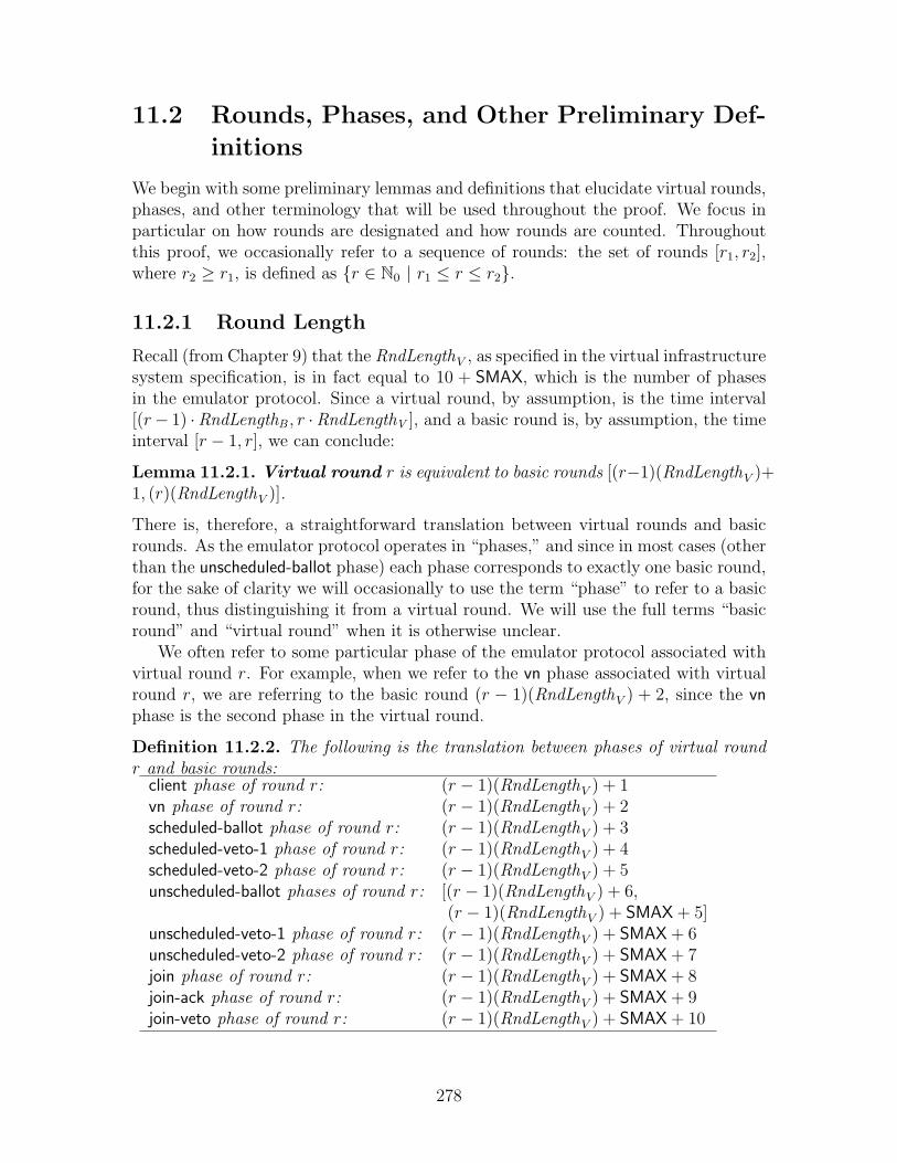
11.2 Rounds, Phases, and Other Preliminary Def-
initions
We begin with some preliminary lemmas and definitions that elucidate virtual rounds,phases, and other terminology that will be used throughout the proof. We focus inparticular on how rounds are designated and how rounds are counted. Throughoutthis proof, we occasionally refer to a sequence of rounds: the set of rounds [r1, r2],where r2 ≥ r1, is defined as {r ∈ N0 | r1 ≤ r ≤ r2}.
11.2.1 Round Length
Recall (from Chapter 9) that the RndLengthV , as specified in the virtual infrastructuresystem specification, is in fact equal to 10 + SMAX, which is the number of phasesin the emulator protocol. Since a virtual round, by assumption, is the time interval[(r− 1) ·RndLengthB , r ·RndLengthV ], and a basic round is, by assumption, the timeinterval [r − 1, r], we can conclude:
Lemma 11.2.1. Virtual round r is equivalent to basic rounds [(r−1)(RndLengthV )+1, (r)(RndLengthV )].
There is, therefore, a straightforward translation between virtual rounds and basicrounds. As the emulator protocol operates in “phases,” and since in most cases (otherthan the unscheduled-ballot phase) each phase corresponds to exactly one basic round,for the sake of clarity we will occasionally to use the term “phase” to refer to a basicround, thus distinguishing it from a virtual round. We will use the full terms “basicround” and “virtual round” when it is otherwise unclear.
We often refer to some particular phase of the emulator protocol associated withvirtual round r. For example, when we refer to the vn phase associated with virtualround r, we are referring to the basic round (r − 1)(RndLengthV ) + 2, since the vnphase is the second phase in the virtual round.
Definition 11.2.2. The following is the translation between phases of virtual roundr and basic rounds:
client phase of round r: (r − 1)(RndLengthV ) + 1vn phase of round r: (r − 1)(RndLengthV ) + 2scheduled-ballot phase of round r: (r − 1)(RndLengthV ) + 3scheduled-veto-1 phase of round r: (r − 1)(RndLengthV ) + 4scheduled-veto-2 phase of round r: (r − 1)(RndLengthV ) + 5unscheduled-ballot phases of round r: [(r − 1)(RndLengthV ) + 6,
(r − 1)(RndLengthV ) + SMAX + 5]unscheduled-veto-1 phase of round r: (r − 1)(RndLengthV ) + SMAX + 6unscheduled-veto-2 phase of round r: (r − 1)(RndLengthV ) + SMAX + 7join phase of round r: (r − 1)(RndLengthV ) + SMAX + 8join-ack phase of round r: (r − 1)(RndLengthV ) + SMAX + 9join-veto phase of round r: (r − 1)(RndLengthV ) + SMAX + 10
278

Notice that each phase of the emulator protocol corresponds to exactly one basicround in the virtual round, with the exception of the unscheduled-ballot-phase, whichlasts for SMAX basic rounds.
11.2.2 Emulator State at the Beginning and End of a Round
We next need some terminology to refer to the state of the emulator process at variouspoints in the execution. In particular, we will be interested in the state of the emulatorat the end of each basic round, and at the end of each virtual round. (Notice that itmakes sense to talk about the end of a virtual round in α, since virtual rounds aresimply defined by intervals of time, not events; hence the virtual round ends whenthe last basic round associated with the virtual round ends.) Since rounds are simplydefined in terms of time, however, the state of a process at the “end of a round” is sofar ill-defined, as multiple events may modify its state at that exact instant in time.Throughout this proof, then, when we refer to the state at the end of a round, wemean the state of a node immediately after the receive event associated with thatround:
Definition 11.2.3. • The state of node i ∈ IB at the end of basic round r isthe state of i immediately after the round r receive event.
• The state of node i ∈ IB at the end of virtual round r is the state of i at theend of the last basic round in virtual round r.
• The state of node i ∈ IB at the beginning of basic round r is the state of iat the end of basic round r − 1, or the initial state if r = 1.
• The state of node i ∈ IB at the beginning of virtual round r is the state ofi at the end of virtual round r − 1, or the initial state if r = 1.
11.2.3 The Current Round
The emulator process for virtual node v keeps track of the current virtual round inthe state variable E(v).rnd i. (Recall that the notation E(v).rnd i refers to the rndstate component of the individual virtual node emulator E(v) associated with nodei.) By simple counting, it is immediately clearly that the emulator correctly countsvirtual rounds:
Lemma 11.2.4. For all i ∈ IB, if i has not failed by the end of basic round ra, wherera is part of virtual round r, then E(v).rnd i = r at the end of basic round ra.
Proof. This lemma follows immediately from the fact that RndLengthV = 10+SMAX,and that there are exactly 10+SMAX basic rounds in the protocol: every client phaseincrements E(v).rnd i by 1.
Notice that this lemma says nothing about the actual behavior of the virtual node;the beginning and end of a virtual round are defined simply by the times at whichthe round starts and finishes, which is itself derived from RndLengthV .
279
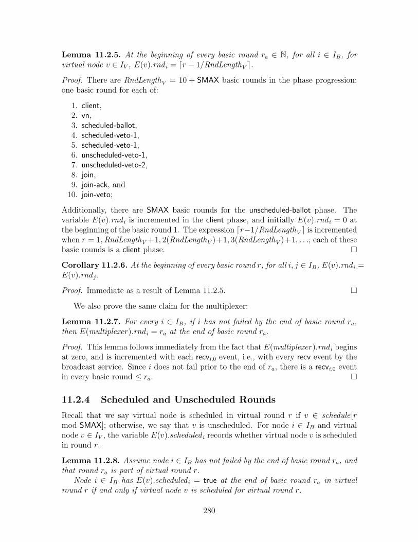
Lemma 11.2.5. At the beginning of every basic round ra ∈ N, for all i ∈ IB, forvirtual node v ∈ IV , E(v).rnd i = dr − 1/RndLengthV e.
Proof. There are RndLengthV = 10 + SMAX basic rounds in the phase progression:one basic round for each of:
1. client,2. vn,3. scheduled-ballot,4. scheduled-veto-1,5. scheduled-veto-1,6. unscheduled-veto-1,7. unscheduled-veto-2,8. join,9. join-ack, and
10. join-veto;
Additionally, there are SMAX basic rounds for the unscheduled-ballot phase. Thevariable E(v).rnd i is incremented in the client phase, and initially E(v).rnd i = 0 atthe beginning of the basic round 1. The expression dr−1/RndLengthV e is incrementedwhen r = 1,RndLengthV +1, 2(RndLengthV )+1, 3(RndLengthV )+1, . . .; each of thesebasic rounds is a client phase.
Corollary 11.2.6. At the beginning of every basic round r, for all i, j ∈ IB, E(v).rnd i =E(v).rnd j.
Proof. Immediate as a result of Lemma 11.2.5.
We also prove the same claim for the multiplexer:
Lemma 11.2.7. For every i ∈ IB, if i has not failed by the end of basic round ra,then E(multiplexer).rnd i = ra at the end of basic round ra.
Proof. This lemma follows immediately from the fact that E(multiplexer).rnd i beginsat zero, and is incremented with each recvi,0 event, i.e., with every recv event by thebroadcast service. Since i does not fail prior to the end of ra, there is a recvi,0 eventin every basic round ≤ ra.
11.2.4 Scheduled and Unscheduled Rounds
Recall that we say virtual node is scheduled in virtual round r if v ∈ schedule[rmod SMAX]; otherwise, we say that v is unscheduled. For node i ∈ IB and virtualnode v ∈ IV , the variable E(v).scheduled i records whether virtual node v is scheduledin round r.
Lemma 11.2.8. Assume node i ∈ IB has not failed by the end of basic round ra, andthat round ra is part of virtual round r.
Node i ∈ IB has E(v).scheduled i = true at the end of basic round ra in virtualround r if and only if virtual node v is scheduled for virtual round r.
280

Proof. Since i has not failed by the end of ra, we know that a recv event for theround r client phase occurs, as the client phase is the first phase in r. At the begin-ning of the client phase, that is, the end of round r − 1, E(v).rnd i = r − 1, as perLemma 11.2.4. During the client phase, first E(v).rnd i is incremented to r, and thenthe flag E(v).scheduled i is set if and only if v ∈ schedule(E(v).rnd i mod SMAX), thatis, if and only if virtual node v is scheduled for virtual round r. The E(v).scheduled i
flag is not modified during any other phase of round r prior to the end of round ra,since node i does not fail in a basic round ≤ ra.
We can thus conclude that any two nodes share the same value for the scheduledflag for the same v at the end of each basic round in a virtual round:
Corollary 11.2.9. Let ra and rb be basic rounds that are part of the same virtualround. Let i, j ∈ IB be two nodes that have not failed by the end of ra and rb,respectively. Then at the end of round ra, E(v).scheduled i = E(v).scheduled j, at theend of round rb.
Proof. Follows immediately from Lemma 11.2.8: if ra and rb are part of virtual roundr, then: if v is scheduled, then both equal true; if v is not scheduled, then both equalfalse.
11.3 Participating in a Virtual Node Emulation
Our goal in this section is to determine when a node i “participates” in emulating avirtual node, and when it does not. We will then show how to construct an “updown”sequence that indicates in which rounds a virtual node v is up, and in which roundsvirtual node v is down. For every consecutive sequence of rounds in which virtualnode v is up, we will show, in the following sections, how to construct an appropriateexecution segment.
In part, this section implies that the “join protocol” works as expected, in thatit discusses how nodes join the emulation and what can be guaranteed of nodesparticipating in the emulation.
11.3.1 Preliminary Definitions
Before discussing node participation, we first need some terminology relating to theschedule. Recall that in each virtual round, the emulator examines the schedule todetermine whether to simulate a broadcast by the virtual node. We therefore definethe notion of “scheduled” as follows:
Definition 11.3.1. We say that virtual node v is scheduled in virtual round r ifv ∈ schedule[r mod SMAX]. Otherwise, we say that virtual node v is unscheduledin virtual round r.
When virtual node v is scheduled for some virtual round r, the emulator for vbehaves differently than when v is unscheduled. Specifically, the emulator for virtual
281

node v uses the “scheduled agreement instance,” rather than the “unscheduled agree-ment instance.” Thus, we define the “last agreement phase” as follows, depending onwhether virtual node v is scheduled:
Definition 11.3.2. For virtual node v ∈ IV and virtual round r > 0, we define thelast agreement phase of v in virtual round r as follows:
• If v is scheduled in round r, then the last agreement phase is the scheduled-veto-2phase.
• If v is unscheduled in round r, then the last agreement phase is the unscheduled-veto-2phase.
We can now determine whether a replica is participating in the emulation of virtualnode v for some given virtual round r. Specifically, a replica is participating in theemulation if it has completed the “join protocol” prior to virtual round r and doesnot fail until the end of the appropriate agreement instance:
Definition 11.3.3. We say that i ∈ IB participates in virtual node v in virtualround r if E(v).joined i = true and E(v).failed i = false at the beginning of virtualround r, and through the end of the last agreement phase of virtual round r.
A related concept is when a given replica “begins” a virtual round; a replica maybegin a virtual round, but fail prior to reaching the end of the agreement instance.Similarly, we may be interested in the case where a replica “completes” a virtualround r, which we define to be the same as the case when a virtual round “begins”the following round r+1; in this case, by the end of virtual round r, i.e., the beginningof virtual round r + 1, i has completed the join protocol and not failed.
Definition 11.3.4. We say that i ∈ IB begins virtual round r for virtual node v ifE(v).joined i = true and E(v).failed i = false at the beginning of virtual round r. Wesay that i ∈ IB completes virtual round r for virtual node v if it begins round r + 1.
Notice that it is immediate from Definition 11.3.3 that if i participates in v in virtualround r, then i also begins r for v. On the other hand, a node i may complete avirtual round r for v, and yet not participate in v in round r; for example, a nodemay not begin round r for v, but may join v in round r and complete round r for v.
Next, we define what it means for a virtual node to be reset in a given virtualround. Specifically, we say that a virtual node is reset when the replicas simulate areset event in the virtual system:
Definition 11.3.5. We say that node i ∈ IB executes a reset of virtual node vin virtual round r if automaton E(v)i executes lines 482–488 (Figure 10-9) in virtualround r.
Next, we define what it means for a replica to join the emulation. Specifically, wesay that a replica joins the emulation when it executes the appropriate lines of code:
Definition 11.3.6. We say that node i ∈ IB joins virtual node v in virtual round rif automaton E(v)i executes lines 462–463 (Figure 10-9) in virtual round r.
282
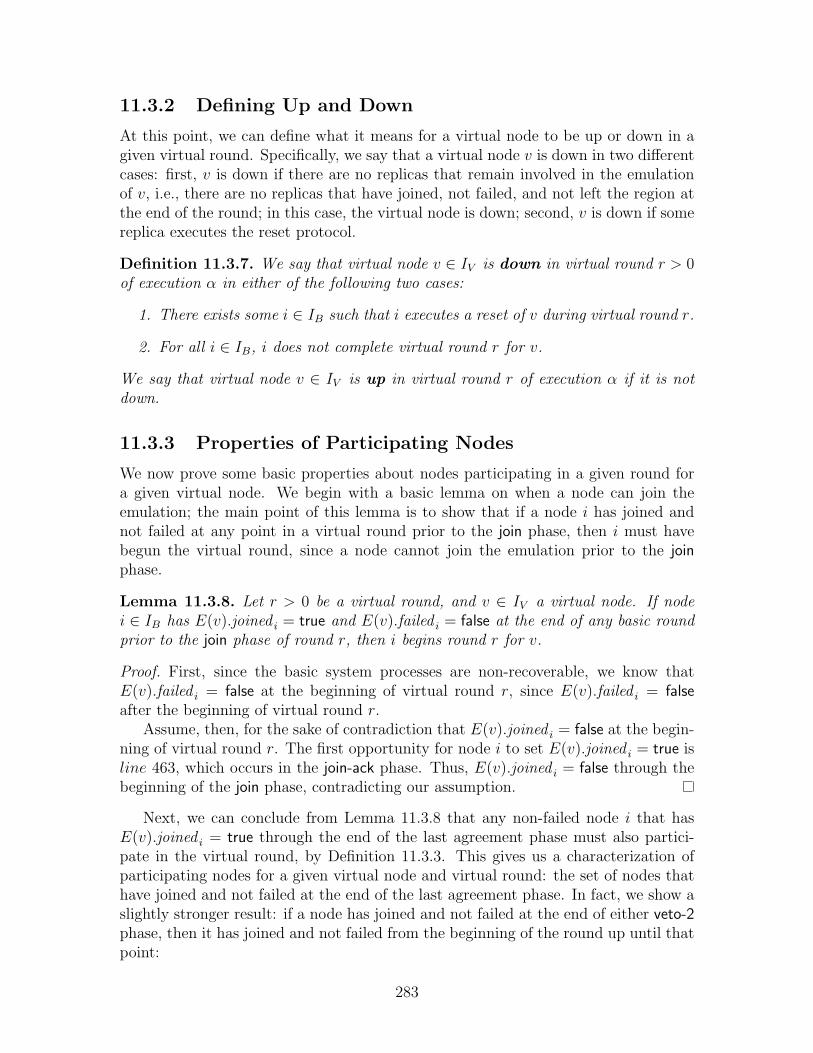
11.3.2 Defining Up and Down
At this point, we can define what it means for a virtual node to be up or down in agiven virtual round. Specifically, we say that a virtual node v is down in two differentcases: first, v is down if there are no replicas that remain involved in the emulationof v, i.e., there are no replicas that have joined, not failed, and not left the region atthe end of the round; in this case, the virtual node is down; second, v is down if somereplica executes the reset protocol.
Definition 11.3.7. We say that virtual node v ∈ IV is down in virtual round r > 0of execution α in either of the following two cases:
1. There exists some i ∈ IB such that i executes a reset of v during virtual round r.
2. For all i ∈ IB, i does not complete virtual round r for v.
We say that virtual node v ∈ IV is up in virtual round r of execution α if it is notdown.
11.3.3 Properties of Participating Nodes
We now prove some basic properties about nodes participating in a given round fora given virtual node. We begin with a basic lemma on when a node can join theemulation; the main point of this lemma is to show that if a node i has joined andnot failed at any point in a virtual round prior to the join phase, then i must havebegun the virtual round, since a node cannot join the emulation prior to the joinphase.
Lemma 11.3.8. Let r > 0 be a virtual round, and v ∈ IV a virtual node. If nodei ∈ IB has E(v).joined i = true and E(v).failed i = false at the end of any basic roundprior to the join phase of round r, then i begins round r for v.
Proof. First, since the basic system processes are non-recoverable, we know thatE(v).failed i = false at the beginning of virtual round r, since E(v).failed i = falseafter the beginning of virtual round r.
Assume, then, for the sake of contradiction that E(v).joined i = false at the begin-ning of virtual round r. The first opportunity for node i to set E(v).joined i = true isline 463, which occurs in the join-ack phase. Thus, E(v).joined i = false through thebeginning of the join phase, contradicting our assumption.
Next, we can conclude from Lemma 11.3.8 that any non-failed node i that hasE(v).joined i = true through the end of the last agreement phase must also partici-pate in the virtual round, by Definition 11.3.3. This gives us a characterization ofparticipating nodes for a given virtual node and virtual round: the set of nodes thathave joined and not failed at the end of the last agreement phase. In fact, we show aslightly stronger result: if a node has joined and not failed at the end of either veto-2phase, then it has joined and not failed from the beginning of the round up until thatpoint:
283

Lemma 11.3.9. Let r > 0 be a virtual round, and v ∈ IV a virtual node. If nodei ∈ IB has E(v).joined i = true and E(v).failed i = false at the end of either (1)scheduled-veto-2 phase or (2) unscheduled-veto-2 phase of round r, then, in eithercase, i has E(v).joined i = true and E(v).failed i = false from the beginning of virtualround r through the end of the specified veto-2 phase.
Proof. We can conclude from Lemma 11.3.8 that node i begins round r. Moreover, ifE(v).joined i = false in any phase prior to—or including—the specified veto-2 phase,then E(v).joined i = false at the end of the veto-2 phase, contradicting our assumption,as there is no opportunity prior to the join-ack phase for i to reset E(v).joined i totrue. Also, since processes in the basic system are non-recoverable, we know thatE(v).failed i = false in all rounds prior to the last agreement phase. Thus, node i hasE(v).joined i = true and E(v).failed i = false from the beginning of round r throughthe end of both the scheduled-veto-2 and the unscheduled-veto-2 phase.
Finally, we prove that the definition of a virtual node being “up” captures some-thing about the real status of the virtual node. Specifically, we show that if thevirtual node is up, then there is at least some i ∈ IB that is participating in theround for v. In fact, we show a slightly stronger result, specifically, that some replicahas joined and not failed at least through the end of the unscheduled-veto-2 phase.(A participating node is only guaranteed to be joined and not failed through the endof the last agreement phase, which for a virtual node scheduled in round r may bethe earlier scheduled-veto-2 phase.)
Lemma 11.3.10. Let r > 0 be a virtual round, and v ∈ IV be a virtual node that isup in virtual round r. Then there exists some node i ∈ IB such that (1) i begins roundr for virtual node v, and (2) E(v).joined j = true and E(v).failed j = false through theend of the join phase of round r.
Proof. First, if there exists any node i ∈ IB such that E(v).joined i = true andE(v).joined i = false at the end of the unscheduled-veto-2 round of round r, then imust begin round r, by Lemma 11.3.9, satisfying our claim.
Assume, then, that at the beginning of the join-ack phase, there is no node i ∈ IB
that has E(v).joined i = true and E(v).failed i = false. In this case, the condition online 445 (Figure 10-9) is not satisfied by any node during the join phase, and thusno join-ack messages are broadcast. Thus, no node i ∈ IB joins v in round r. As aresult, virtual node v must be down in round r: either some node j ∈ IB executes thereset protocol, setting E(v).joined j = true, or at the end of the virtual round thereare no nodes j ∈ IB such that E(v).joined j = true. Either way, v is down in round r,contradicting the assumption that v is up in round r.
11.3.4 Delineating an Execution
We now define what it means for virtual rounds r1 and r2 to “delineate” an execution:
Definition 11.3.11. Let r1 ∈ N, r2 ∈ N ∪ {∞}, r1 ≤ r2. We say that 〈r1, r2〉 is anepoch, delineated by [r1, r2], of virtual node v ∈ IV in α if the following properties
284
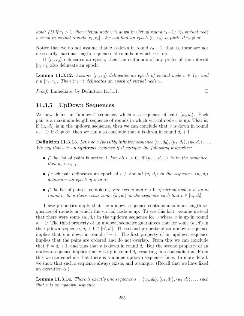
hold: (1) if r1 > 1, then virtual node v is down in virtual round r1−1; (2) virtual nodev is up in virtual rounds [r1, r2]. We say that an epoch 〈r1, r2〉 is finite if r2 6=∞.
Notice that we do not assume that v is down in round r2 + 1; that is, these are notnecessarily maximal length sequences of rounds in which v is up.
If 〈r1, r2〉 delineates an epoch, then the endpoints of any prefix of the interval[r1, r2] also delineate an epoch:
Lemma 11.3.12. Assume 〈r1, r2〉 delineates an epoch of virtual node v ∈ IV , andr ∈ [r1, r2]. Then 〈r1, r〉 delineates an epoch of virtual node v.
Proof. Immediate, by Definition 11.3.11.
11.3.5 UpDown Sequences
We now define an “updown” sequence, which is a sequence of pairs 〈ui, di〉. Eachpair is a maximum-length sequence of rounds in which virtual node v is up. That is,if 〈ui, di〉 is in the updown sequence, then we can conclude that v is down in roundui − 1; if di 6=∞, then we can also conclude that v is down in round di + 1.
Definition 11.3.13. Let s be a (possibly infinite) sequence 〈u0, d0〉, 〈u1, d1〉, 〈u2, d2〉, . . ..We say that s is an updown sequence if it satisfies the following properties:
• (The list of pairs is sorted.) For all i > 0, if 〈ui+1, di+1〉 is in the sequence,then di < ui+1.
• (Each pair delineates an epoch of v.) For all 〈ui, di〉 in the sequence, 〈ui, di〉delineates an epoch of v in α.
• (The list of pairs is complete.) For ever round r > 0, if virtual node v is up inround r, then there exists some 〈ui, di〉 in the sequence such that r ∈ [ui, di].
These properties imply that the updown sequence contains maximum-length se-quences of rounds in which the virtual node is up. To see this fact, assume insteadthat there were some 〈ui, di〉 in the updown sequence for v where v is up in rounddi +1: The third property of an updown sequence guarantees that for some 〈u′, d′〉 inthe updown sequence, di + 1 ∈ [u′, d′]. The second property of an updown sequenceimplies that v is down in round r′ − 1. The first property of an updown sequenceimplies that the pairs are ordered and do not overlap. From this we can concludethat j′ = di + 1, and thus that v is down in round di. But the second property of anupdown sequence implies that v is up in round di, resulting in a contradiction. Fromthis we can conclude that there is a unique updown sequence for v. In more detail,we show that such a sequence always exists, and is unique. (Recall that we have fixedan execution α.)
Lemma 11.3.14. There is exactly one sequence s = 〈u0, d0〉, 〈u1, d1〉, 〈u2, d2〉, . . . suchthat s is an updown sequence.
285
Proof. Claim 1: First, we argue that there exists some ui = r if and only if v is downin round r− 1 and up in round r. If 〈r, di〉 ∈ s, it is immediately clear that v is downin round r− 1 and up in round r. Assume, then, that v is down in r− 1 and up in r:then there exists some 〈u, d〉 ∈ s such that r ∈ [u, d]; yet r − 1 /∈ [u, d] since v is upin every round in [u, d]; thus we conclude that u = r.
Claim 2: Next, we argue that there exists some di = r if and only if v is up inround r and down in round r + 1. Assume v is up in round r and down in roundr + 1: then there exists some 〈u, d〉 ∈ s such that r ∈ [u, d]; yet r + 1 /∈ [u, d], sincev is up in every round in [u, d]; thus we conclude that d = r. Alternatively, assumethat 〈ui, r〉 ∈ s. It follows immediately that v is up in round r. Assume for the sakeof contradiction that v is also up in round r + 1. Then there is some 〈u′, d′〉 suchthat r + 1 ∈ [u′, d′], and where v is down in round u′ − 1. From this we concludethat r + 1 ≤ d′, and hence r < d′. There are thus two possibilities for u′: eitheru′ ≤ u, which contradicts our assumption that the pairs in s are sorted and strictlyincreasing, or u < u′, which contradicts the assumption that v is down in orund u′−1.
Claim 3: Finally, we argue that there exists some di = ∞ if and only if thereexists some round r such that v is up in every round ≥ ∞. Assume there existssome di = ∞. Then by assumption, v is up in every round ≥ ui. Assume insteadthat there exists some round r such that v is up in every round ≥ r. Assume for thesake of contradiction that every di 6= ∞. In this case, there must exist some 〈ui, di〉were di > r. Moreover, there must exists some 〈ui+1, di+1〉 where di < ui+1. But thiscontradicts our assumption that v is down in round ui+1 − 1.
Conclusion: It follows immediately from these three claims that there is exactlyone updown sequence s: Given execution α, we can determine the exact set of ui anddi in the updown sequence; we can construct the updown sequence by sorting theui and di and matching them. (No other arrangement of the ui and di can yield anupdown sequence due to the ordering property.)
We thus define updown(v) to be the (unique) updown sequence for v:
Definition 11.3.15. For all v ∈ IV , define updown(v) to be the unique updownsequence for v.
11.4 Resetting a Virtual Node
In this section, we present a series of lemmas and invariants that describe the state ofthe virtual node after it is reset. Most of the lemmas proved in this section are relatedto the state variables last-reset and last-good-state. Recall that last-reset stores thevirtual round in which, conceptually, the virtual node was reset; last-good-state storesthe initial state of the virtual node. One of the main conclusions of this section (seeCorollary 11.4.5) is that this intuition is correct: if some 〈r1, r2〉 delineates a finiteepoch of virtual node v, and hence v is down in round r1 − 1, then each node thatbegins virtual round r ∈ [r1, r2] has last-reset = r1 − 1 at the beginning of round r.(In fact, we extend this claim slightly to include the case where r = r2 + 1; that is,the claim holds at the end of virtual round r2 as well.)
286
We begin with a basic lemma relating last-reset and prev-rnd : for each virtualnode emulator, for each node in the system, these values are non-decreasing, andlast-reset ≤ prev-rnd ≤ rnd .
Lemma 11.4.1. For all i ∈ IB, for all v ∈ IV :
1. E(v).last-reset i and E(v).prev-rnd i are non-decreasing.
2. E(v).last-reset i ≤ E(v).prev-rnd i ≤ E(v).rnd i.
Proof. We show this by induction on events in α. Initially, both conclusions areclearly true. Let e be the first event that causes one of the conclusions to be violatedfor any j ∈ IB. Then e must be a recv event, as no other action modifies these statevariables, and e must occur during one of the following phases, which are the onlyones in which these state variables are modified:
• The client phase increments E(v).rnd j by one. Clearly, the invariant is main-tained.
• The scheduled-veto-2 phase sets E(v).prev-rnd j to E(v).rnd j. Prior to event e,we know that E(v).prev-rnd j ≤ E(v).rnd j; thus, conclusion (1) is maintained.Prior to e, E(v).last-reset j ≤ E(v).rnd j; thus, after e we can conclude thatE(v).last-reset j ≤ E(v).prev-rnd j, and hence conclusion (2) is maintained.
• The unscheduled-veto-2 phase sets E(v).prev-rnd j to E(v).rnd j, as in the pre-viously discussed scheduled-veto-2 phase, hence the invariant is maintained.
• The join-ack updates E(v).prev-rnd j and E(v).last-reset j with data from amessage that was broadcast by some other node k ∈ IB. Since e is the firstevent to violate the invariant for any j ∈ IB, we know that the state of k satisfiedthe invariant when the message was sent, and hence the values contained in themessage also satisfy the invariant.
• The join-veto sets both E(v).last-reset j and E(v).prev-rnd j to E(v).rnd j, andthus the invariant is maintained.
We next consider what happens in a virtual round when a virtual node v is reset.Specifically, we assume that 〈r1, r2〉 delineates a finite epoch of some virtual node v.This implies that v is down in round r1 − 1. Our goal (informally) is to show thatduring each of the virtual rounds in the range [r1, r2], for each emulator of virtual nodev, the last-reset variable is set to round r1−1. That is, the last-reset variable reflectsthe most recent round in which the virtual node is reset. This requires a sequenceof lemmas. First, we show in Lemma 11.4.2 that this fact is true at the beginningof round r1. Second, we extend Lemma 11.4.2 to show that last-reset ≥ r1 − 1 notonly at the beginning of round r1, but also in every round ≥ r1. Third, we show aninvariant that is, loosely, the converse of the preceding lemmas: if last-reset is set tosome value r, then the virtual node is down in virtual round r. Finally, we conclude
287

with a corollary proving the main claim that last-reset always reflects the most recentround in which virtual node v was reset.
Notice that this sequence of lemmas plays a key role in showing that the “resetprotocol” works correctly. For example, from this argument, we can conclude thatall the nodes emulating v at the beginning of virtual round r1 are in agreement thatvirtual node v was reset in virtual round r1−1. This set of lemmas therefore precludesthe possibility that some node was participating in the emulation, and yet was notaware that the “reset” protocol was being invoked.
We begin by arguing that at the beginning of virtual round r1, if v is down inround r1 − 1 and the reset protocol has worked correctly, then the last-reset variableof each node that begins round r1 is set to r1 − 1. We also show that prev-rnd is setto r1 − 1 at the beginning of round r1 − 1. The prev-rnd pointer, intuitively, keepstrack of the last “locally good” round, and is discussed further in Section 11.5. It isalso set to r1 − 1 during the reset protocol.
Lemma 11.4.2. For virtual round r1 > 1, assume virtual node v ∈ IV is down inround r1 − 1 in execution α. Assume i ∈ IB begins round r1 for v. Then at thebeginning of round r1:
1. E(v).last-reset i = r1 − 1;
2. E(v).prev-rnd i = r1 − 1 .
Proof. Since virtual node v is down in α in round r1−1 one of two situations occurredin round r1 − 1, by the definition of “down”:
1. For some k ∈ IB, k resets v in round r1−1. Let J be the set of nodes that resetv in round r1− 1. (Recall that we say that a node resets a virtual node when itexecutes specific lines of pseudocode, described in Definition 11.3.5.) Then forevery j ∈ J , the conclusions of the lemma are immediately satisfied, as the resetpseudocode occurs during the last phase of round r1−1, the join-veto phase, andsets the state variables as described. (By Lemma 11.2.4, E(v).rnd j = r1 − 1 atthe beginning and end of the join-veto phase, and hence throughout the join-vetophase.)
Notice that since at least one node resets v, we know that v ∈ schedule[r1 − 1mod SMAX]; otherwise, the reset pseudocode cannot be executed in virtualround r1 − 1.
Assume for the sake of contradiction that there exists some j ∈ IB, j /∈ J ,where j begins round r1. Thus, at the end of round r1− 1, E(v).joined j = true.Therefore node j has E(v).joined j = true prior to the recv event for the join-ackphase for round r1 − 1. (There is no other opportunity for j to set joined totrue, as by assumption j does not execute the reset code.) Since v is scheduledfor round r1− 1 and j has joined set to true, node j sets E(v).outgoing-msg j toveto, broadcasting a veto message in the join-veto phase.
Since j has E(v).joined j = true at the end of the join-ack phase, node j is withindistance RB/4 of loc(v) at the end of the join-ack phase, i.e., the beginning of the
288

join-veto phase. Similarly, i has E(v).reset i = true at the end of the join-vetophase; otherwise, it would not execute the reset pseudocode. Thus, node iwas within distance RB/4 of loc(v) at the end of the join-ack phase, i.e., thebeginning of the join-veto phase.
Hence, nodes j and k are within distance RB/2 of each other, and the broadcastservice guarantees (by Lemma 8.1.40) that k receives either a collision or a vetomessage in the join-veto phase. If node k receives either a collision or vetomessage in the join-veto phase, however, then automaton E(v)k would not haveexecuted lines 482–488, as assumed, leading to a contradiction.
2. For all j ∈ IB, either E(v).failed j = true or E(v).joined j = false at the end ofvirtual round r1 − 1, that is, the beginning of round r1. This contradicts ourassumption that node i begins round r1.
The next lemma, Lemma 11.4.3, extends Lemma 11.4.2 in the following manner:Lemma 11.4.2 shows that immediately after a virtual node is reset, the variablelast-reset is set appropriately for each emulator; Lemma 11.4.3 shows that last-resetis always at least as large as the most recent round in which the virtual node wasreset. The proof follows from the fact that last-reset is assigned a new value duringthe reset pseudocode: during the join pseudocode, its value is copied from anotheremulator. This lemma depends primarily on Lemma 11.4.2, along with the claim thatthe join protocol works correctly:
Lemma 11.4.3. Let 〈r1, r2〉 delineates a finite epoch of v. If i has E(v).joined i = trueand E(v).failed i = false at the beginning of some basic round ra and ra is part of virtualround r ≥ r1, then E(v).last-reset i ≥ r1 − 1 at the beginning of basic round ra.
Proof. First, consider the case where ra is the first basic round in virtual round r1:Lemma 11.4.2 states that if i begins virtual round r1, then E(v).last-reset j = r1 − 1at the beginning of virtual round r1, and hence at the beginning of the first basicround in virtual round r1.
Consider, for the sake of contradiction, the first basic round rb associated withvirtual round r′ ≥ r1 in which some node k has joined and not failed at the beginningof basic round rb and also has E(v).last-resetk < r1 − 1 at the beginning of basicround rb. There are two phases in which E(v).last-resetk is updated during a basicround: join-veto and join-ack. There are also the only phases in which E(v).joinedk
is set to true; there are no phases in which E(v).failedk is set to false. Thus it issufficient to examine these two phases.
First, E(v).last-resetk and E(v).joinedk are modified during the reset pseu-docode in lines 482–488 (Figure 10-9). In this case, E(v).last-resetk is set to rnd =r′ ≥ r1. (As usual, the relationship between rnd and r′ follows from Lemma 11.2.4.)
Second, E(v).last-resetk and E(v).joinedk are modified during the join-ack phasein lines 460–463 (Figure 10-9). In this case, E(v).last-resetk is set to a value that wasbroadcast by some other replica k′ during the join-ack phase. But we know that at the
289

beginning of the join-ack phase, node k′ has E(v).joinedk′ = true and E(v).failedk′
= false, since otherwise k′ would not send a join acknowledgment (lines 445–446,Figure 10-9). Thus, by the inductive hypothesis, E(v).last-resetk′ ≥ r1 − 1 whenk′ broadcasts the join acknowledgment, contradicting our assumption that k setsE(v).last-resetk < r1 − 1.
The following lemma shows, loosely, the converse of Lemma 11.4.2. Lemma 11.4.2argues that if v is down in some virtual round r−1 and up in some virtual round r, thenthe last-reset state variable has value r − 1 (immediately afterward). The followinginvariant argues that if last-reset state variable has value r− 1, then the virtual nodewas down in virtual round r − 1. It then follows, as shown in Corollary 11.4.5, thatthe virtual node is up in the following virtual round r.
Lemma 11.4.4. If E(v).last-reset i = r, for some i ∈ IB, r ∈ N, then v is down invirtual round r.
Proof. The proof proceeds by induction on events in α. Assume for the sake ofcontradiction that event e is the first event that causes the invariant to be violatedfor some j ∈ IB. Then e must be a recv event that updates E(v).last-reset i for somei ∈ IB. There are two phases in which E(v).last-reset i is modified. First, in thejoin-veto phase, E(v).last-reset j is set to E(v).rnd j , which immediately impliesby definition that v is down in round E(v).rnd j . Second, in the join-ack phase,E(v).last-reset j is set to a value broadcast by another k ∈ IB, specifically the valueof r′ = E(v).last-resetk at the beginning of the join-ack phase. Since prior to evente the invariant is satisfied, we know that virtual node v is down in virtual round r′,and thus after event e in E(v).last-reset j. In both cases, the invariant is maintainedafter event e, contradicting our assumption.
We can then show the following corollary. This result is perhaps the most frequentlyused claim from this section.
Corollary 11.4.5. If 〈r1, r2〉 delineates a finite epoch of v and i begins virtual roundr ∈ [r1, r2 + 1], then E(v).last-reset i = r1 − 1 at the beginning of virtual round r.
Proof. By Lemma 11.4.3, we know that E(v).last-reset i ≥ r1 at the beginning ofvirtual round r. Assume, then, for the sake of contradiction that E(v).last-reset i = r′
at the beginning of virtual round r, and virtual round r′ ≥ r1. By Lemma 11.4.4,virtual node v is down in round r′. We also know that r′ ≤ r − 1 by Lemma 11.4.1,as E(v).last-reset i ≤ E(v).rnd i at the end of virtual round r − 1. Thus, r1 ≤ r′ ≤ r2
and v is down in round r′. This contradicts the assumption that 〈r1, r2〉 delineatesan epoch in which v is up in each round.
We conclude with one final corollary on the relationship between last-reset atdifferent emulators for virtual node v:
Corollary 11.4.6. Assume virtual node v is up in virtual round r. For some i, j ∈ IB:
1. If i and j begin virtual round r for v, then E(v).last-reset i = E(v).last-reset j atthe beginning of virtual round r.
290
2. If i and j begin virtual round r for v, then E(v).last-reset i = E(v).last-reset j
throughout virtual round r.
Proof. Choose r′ to be the largest round < r such that virtual node v is down inr′. Then 〈r′ + 1, r〉 delineates a finite epoch of v. Conclusion (1) holds by Corol-lary 11.4.5: E(v).last-reset i = r′ and E(v).last-reset j = r′. Conclusion (2) followssince E(v).last-reset is non-decreasing and ≤ r through the end of virtual round r, byLemma 11.4.1; thus r′ ≤ E(v).last-reset ≤ r: if E(v).last-reset > r′ at any point dur-ing virtual round r, then we can conclude by Lemma 11.4.4 that v is down in roundE(v).last-reset , contradicting our prior assumption that v is up for every round inrange [r′ + 1, r]. Thus, E(v).last-reset is equal to r′ throughout virtual round r forboth i and j.
11.5 Round Colors
This section contains some of the key definitions and lemmas used in the proof. Weidentify “good rounds” and “bad rounds,” as well as “green rounds” and “red rounds.”Having assigned colors to rounds, we can then argue about which combinations ofcolors can co-exist in a virtual round; much of this proof has a flavor similar tothe analysis of the three-phase-commit protocols. (See [95, 96] and the discussion inSection 10.1.6 on the similarities.)
We begin in Section 11.5.1 by defining green rounds and red rounds, and alsogood rounds and bad rounds. The key definitions here are Definition 11.5.1 andDefinition 11.5.2.
In Section 11.5.2, we take a detour through the analysis of the join protocol toshow that when a node joins the emulation, it correctly receives the ballot and colorinformation. The key lemma in this argument that is used in later sections of thisproof is Lemma 11.5.3. As a result, we can conclude that the color of a round (i.e.,whether it is green or red) and the status of a round (i.e., whether it is good or bad)persist, eventually as nodes join and leave (see Lemmas 11.5.4 and 11.5.5).
In Section 11.5.3, we discuss the relationship between good rounds and greenrounds, showing that all green rounds are good (Corollary 11.5.7), and the rela-tionship between bad rounds and red rounds, showing that all red rounds are bad(Lemma 11.5.9). In the process of proving these lemmas, we show that if two replicasassign a color to a virtual round, then that color differs by at most one shade.
In Section 11.5.4, we relate the value of the prev-rnd pointer (in the emulator state)to the status of a round. Intuitively, the prev-rnd pointer remembers the most recentround that a node, locally, believes to be good; globally, across all the emulators, wecan conclude from the results in Section 11.5.3 that the round in prev-rnd is not red,as is stated in Lemma 11.5.12.
Finally, in Section 11.5.5, we show (in Corollary 11.5.16) that if a round is not redfor some virtual node v, then it has a unique “proposer” and a unique “ballot” (seeDefinition 11.5.17). Notice that when combined with the results from Section 11.5.4,we can conclude that any round stored in the prev-rnd pointer has a unique proposerand a unique ballot. This fact will be key in reconstructing executions of the virtual
291
node from the ballot history. Moreover, since there is a unique ballot for the virtualround, we can conclude that all the replicas with a round r ballot agree on that ballot.We show in Corollary 11.5.20 that in fact all the nodes that complete virtual roundr—or any larger round prior to v being down—agree on the ballot for round r.
11.5.1 Definitions
In this section, we define what it means for a round to be a “good round” a “badround,” a “green round,” or a “red round.” We begin with the definition of a “greenround.” A green round is, essentially, an ideal round in that at least one of the virtualnode emulators detects no problems and hence designates it as green. A “red round,”by contrast, is a round in which at least one of the virtual node emulators detectssignificant problems, and hence designates it as red.
Definition 11.5.1. Let v ∈ IV be a virtual node, and r > 0 be a virtual round.
• We say that round r is a green round for v if there exists some node i ∈ IB
that participates in round r and has E(v).round-status [r ]i = green at the end ofthe last agreement phase of virtual round r.
• We say that round r > 0 is a red round for v if there exists some node i ∈ IB
that participates in virtual round r and E(v).round-status [r ]i = red at the endof the last agreement phase of virtual round r.
Notice that a round is designated as green or red based on only a single nodelocally assigning a virtual round to be red or green. That is, a round is green or redbased on a local observation. By contrast, we designate a round as good or bad basedon the state of all participating nodes. We say that a round is a “good round” ifevery participating emulator considers the round to be green or yellow. Similarly, wedesignate a virtual round as bad if every participating emulator consider the roundto be red or orange.
Definition 11.5.2. Let v ∈ IV be a virtual node, and r > 0 be a virtual round.
• We say that round r is a good round for v ∈ IV if for every i ∈ IB that partici-pates in round r, either E(v).round-status [r ]i = green or E(v).round-status [r ]i =yellow at the end of the last agreement phase of virtual round r.
• We say that round r is a bad round for v ∈ IV if for every i ∈ IB that partici-pates in round r, either E(v).round-status [r ]i = red or E(v).round-status [r ]i =orange at the end of the last agreement phase of virtual round r.
11.5.2 Extending the Color Definitions: the Join Protocol,Revisited
Notice that each of the definitions in Section 11.5.1 specifies the color of some virtualround r based only on the state of the nodes at the end of the last agreement phase
292

of round r. In fact, the color designated at the end of the last agreement phasepermanently fixes the color designation of a virtual round, until the virtual node isreset. (After a virtual node is reset, its prior history is no longer relevant.)
This fact follows from the fact that after the last agreement phase of virtual roundr, the color designation of a round is modified only during the join and reset phases;the join phases simply transmit the already-determined color information to newnodes; the reset phase only modifies the color information when the virtual node is,in fact, reset. Thus, this section begins with a technical lemma which shows that thejoin protocol acts as expected, and concludes with the claim that the color designationis unchanged after the last agreement phase.
In more detail, the first lemma here argues, essentially, that if some node i hassome particular setting for the state variable round-status [r], then either node i itselfwas participating in virtual round r, or node i received a copy of round-status [r](either directly or indirectly) from some node j that itself was participating in virtualround r. The same property also holds for the state stored in ballot [r].
In the following lemma, the virtual round r represents the virtual round of in-terest, in terms of round-status [r] and ballot [r] The round r′ ≥ r represents the“current” virtual round, i.e., the virtual round during which the state of node i isbeing observed. Basic round ra is a basic round associated with virtual round r, andbasic round rb is a basic round associated with virtual round r′. More specifically,basic round ra is the last agreement phase of virtual round r, i.e., the basic roundin which the round-status [r] and ballot [r] data structures are updated. Basic roundrb is the “current” phase, i.e., the the phase after which the state of node i is beingobserved. While seemingly a small building block for the main lemmas in this section,Lemma 11.5.3 is actually used several times in later sections of the proof to show thatthe join protocol acts as expected.
Lemma 11.5.3. Assume that 〈r1, r2〉 delineates an epoch of virtual node v ∈ IV inα, and let r, r′ ∈ [r1, r2] be virtual rounds, r′ ≥ r. Let ra be the basic round associatedwith the last agreement phase of virtual round r, and let rb be a basic round in virtualround r′, rb ≥ ra.
If node i ∈ IB has E(v).joined i = true and E(v).failed i = false at the end of basicround rb, then there exists some j ∈ IB where j particpates in virtual round r, and:
- at the end of basic round ra, E(v).ballot [r ]i = E(v).ballot [r ]j at the end of basicround rb;
- at the end of basic round ra, E(v).round-status [r ]i = E(v).round-status [r ]j atthe end of basic round rb.
Proof. We proceed by induction on basic rounds. For the base case, consider roundrb = ra: Since node i itself has E(v).joined i = true and E(v).failed j = false at the endof round ra, then we choose j = i and the criteria are met since node i participatesin round r by Lemma 11.3.9.
For the sake of contradiction, let rb > ra be the first basic round in whichthe lemma fails to be true. Thus, in round rb, node i must have modified ei-ther E(v).joined i, E(v).ballot [r ]i or E(v).round-status [r ]i. After the last agreement
293

phase of round r, i.e., after round ra, there are only two phases in which i modifiesE(v).round-status [r ]i or E(v).round-status [r ]i: when i joins v and when i resets v.Similarly, these are the only two phases in which i sets E(v).joined i to true. (Sincenode i is unrecoverable, it cannot have set E(v).failed i to false.)
First, we can conclude that node i does not reset v in round r′, since r′ ∈ [r1, r2],and hence by assumption v is up in round r.
Thus, we can conclude that i must join v in basic round rb. In that case, however,node j received a round rb message from some other node k that had E(v).joinedk =true and E(v).failedk = false at the beginning of basic round rb; moreover, since icopied the ballot and round status values from the message, we can conclude thatnode k also had ballot or round status values causing the lemma to be violated,contradicting our assumption that rb is the first such basic round.
We can now conclude that if a round is designated as good or bad at the end of thelast agreement phase, then every node continues to designate the round accordingly,until the virtual node is reset:
Lemma 11.5.4. Assume that 〈r1, r2〉 delineates a finite epoch of virtual node v ∈ IV
in α. Let r ∈ [r1, r2] be a virtual round. If i ∈ IB completes virtual round r2 for v,then we conclude the following:
1. If round r is good, then E(v).round-status [r ]i ∈ {green, yellow} at the end ofround r2.
2. If round r is bad, then E(v).round-status [r ]i ∈ {red, orange} at the end of roundr2.
3. If round r is not red, then E(v).round-status [r ]i 6= red at the end of round r2.
Proof. Let basic round ra be the last agreement phase of virtual round r, and let rb
be the last basic round in virtual round r2; thus rb > ra. Since i ∈ IB completesround r2, we know that E(v).joined i = true and E(v).failed i = false at the end ofbasic round rb. Therefore by Lemma 11.5.3, we conclude that there exists somej ∈ IB where j participates in virtual round r and at the end of basic round ra,E(v).round-status [r ]j = E(v).round-status [r ]i at the end of round r2.
If round r is good, since j participates in r, we know that E(v).round-status [r ]j =green or E(v).round-status [r ]j = yellow at the end of round ra by Definition 11.5.2,which leads to the desired conclusion.
Similarly, if round r is bad, since j participates in round r, we know that thestatus E(v).round-status [r ]j = red or E(v).round-status [r ]j = orange at the end ofround ra by Definition 11.5.2, which leads to the desired conclusion.
Similarly, if round r is not red, then since j participates in round r, we know thatE(v).round-status [r ]j 6= red at the end of round r1 by Definition 11.5.1, which leadsto the desired conclusion.
We can also draw conclusions relating to green and red rounds: if a node designatesa round as green or red at the end of a virtual round, then the virtual round is greenor red:
294

Lemma 11.5.5. Assume that 〈r1, r2〉 delineates a finite epoch of virtual node v ∈ IV
in α. Let r ∈ [r1, r2] be a virtual round. If i ∈ IB completes virtual round r2, then weconclude the following:
1. If E(v).round-status [r ]i = green at the end of round r2, then round r is green.
2. If E(v).round-status [r ]i = red at the end of round r2, then round r is red.
Proof. Let basic round ra be the last agreement phase of virtual round r, and let rb
be the last basic round in virtual round r2; thus rb > ra. Since i ∈ IB completesround r2, we know that E(v).joined i = true and E(v).failed i = false at the end ofbasic round rb. Therefore by Lemma 11.5.3, we conclude that there exists somej ∈ IB where j participates in virtual round r and at the end of basic round ra,E(v).round-status [r ]j = E(v).round-status [r ]i at the end of round r2.
If E(v).round-status [r ]i = green at the end of round r2, then E(v).round-status [r ]j =green at the end of the last agreement phase of r, and hence by definition round r isgreen.
Similarly, if E(v).round-status [r ]i = red at the end of round r2, then the statusE(v).round-status [r ]j = red at the end of the last agreement phase of r, and henceby definition round r is red.
11.5.3 Relating Good, Bad, Green, and Red Rounds
In this section, we prove two key lemmas that relate green rounds with good roundsand red rounds with bad rounds. Specifically, we show the following two properties:
• (Corollary 11.5.7) If a virtual round r is green for virtual node v, then it is goodfor v. Recall that a virtual round is green if even one (participating) replicadesignates it as green; a virtual round is good only if every participating replicadesignates it as green or yellow. This lemma plays a key role in proving thatthe protocol has the desired agreement property: in any good round, we willshow that the replicas agree on an execution of the virtual node; however, anindividual emulator may not be able to detect locally whether a round is goodor bad. If, however, an emulator determines (locally) that a round is green, thenthis property guarantees that the round is also good. Thus, in later sectionsof this proof (for example, Corollary 11.7.12), we use this property to showthat under certain conditions (i.e., when the round is green), an emulator canhave confidence that a round is good, which will imply that agreement has beenreached.
• (Lemma 11.5.9) If a virtual round r is red for virtual node v, then it is badfor v. As in the first property, a virtual node is red if even one (participating)replica designates it as red; a virtual round is bad only if every participatingreplica designates it as red or orange. In later sections, the contrapositive of thislemma plays a key role in ensuring that all the replicas have sufficient data toreconstruct the virtual node execution that has been chosen by the agreementprotocol: we will show (in Corollary 11.5.18) that if a round is not red for some
295

round r, then every emulator has the required ballot information about thatround; if any emulator designates a round as green or yellow, then by definitionit is not a bad round; hence by the contrapositive of Lemma 11.5.9, we canconclude that every emulator has enough data to reconstruct the virtual nodeexecution.
Our first goal is to show that every green round is a good round. We instead provea somewhat more general lemma: instead of assuming that the round is green (whichrequires a participating node to designated the round as green), we assume only thatsome non-failed node within distance 3RB/4 of loc(v)V designates the round as green.Note that this node may not be participating in emulating v. The desired result thenfollows as an immediate corollary, as in a green round there is a participating nodethat satisfies the required conditions.
Lemma 11.5.6. Let v ∈ IV be a virtual node, r > 0 a virtual round, and i ∈ IB anode that is non-failed through the end of the last agreement phase. If the followingtwo conditions hold:
1. E(v).round-status [r ]i ∈ {green,⊥} at the end of the last agreement phase ofvirtual round r; and
2. node i is within distance 3RB/4 of loc(v)V at the beginning of the last agreementphase of virtual round r;
Then virtual round r is good for v.
Proof. We need to show for every j ∈ IB, if j participates in virtual round r, theneither E(v).round-status [r ]i = green or E(v).round-status [r ]i = yellow at the end ofthe last agreement phase of virtual round r.
Choose some j ∈ IB that participates in virtual round r. Assume, for the sakeof contradiction, that E(v).round-status [r ]j ∈ {red, orange} at the end of the lastagreement of virtual round r. There are two nearly identical cases depending onwhether v is scheduled or unscheduled in virtual round r.
First, assume that v is scheduled in r. At a high level, the argument proceedsas follows: since j has designated round r as red or orange, we can show that jbroadcasts a veto message in the scheduled-veto-2 phase; as a result, node i eitherreceives the veto message or detects a collision in the scheduled-veto-2 phase; thuswe conclude that if i believes the round to be green, then i downgrades round r to ayellow round, resulting in a contradiction. We now proceed in more detail.
The first part of the argument involves showing that j broadcasts a message inthe scheduled-veto-2 phase. Notice that at the end of the scheduled-veto-2 phase, jsets E(v).round-status [r ]j equal to E(v).scheduled-statusj, from which we concludethat E(v).scheduled-statusj ∈ {red, orange} at the end of the scheduled-veto-2 phase.
Notice, however, that during the scheduled-veto-2 phase recv event, scheduled-statuscan be updated to yellow, but not to red or orange. Thus, we can assume thatE(v).scheduled-statusj ∈ {red, orange} prior to the scheduled-veto-2 phase of round r.
296

Specifically, the latest that E(v).scheduled-statusj can be updated to red or orange isthe recv event of the scheduled-veto-1 phase.
We now argue that this fact implies the following: at the end of the scheduled-veto-1recv event, the message buffer E(v).outgoing-msg j = 〈vn, v, veto〉. In particular thereare three conditions which must be met at the end of the recv event for this to betrue:
• E(v).scheduled-statusj ∈ {red, orange}: as already argued.
• E(v).joined j = true: since j participates in round r, we know that E(v).joined j =true through the end of the scheduled-veto-2 phase.
• E(v).scheduled j = true: as already assumed.
We know that node j is within distance RB/4 of loc(v) at the beginning of thescheduled-veto-2 phase, since E(v).joined j = true.
We now argue that this contradicts the assumption that i has designated theround as green. By assumption, we also know that i is within distance 3RB/4of loc(v) at the beginning of the last agreement phase, i.e., the scheduled-veto-2phase. Thus nodes i and j are within distance RB of each other at the begin-ning of the scheduled-veto-2 phase, and hence by Lemma 8.1.40, node i either re-ceives the veto message from j, or detects a collision. In either case, however, ifE(v).scheduled-status i ∈ {⊥, green}, then E(v).scheduled-status i is set to yellow.Thus, we know that E(v).scheduled-status i 6= green, contradicting our assumptionon i.
Next, we consider the case where v is not scheduled in round r. The argument isidentical, except that the scheduled-veto-2 phase is replaced with the unscheduled-veto-2phase, and the protocol updates round-status [r ] directly, rather than scheduled-status .In more detail, notice that if E(v).round-status [r ]j is red or orange at the end of theunscheduled-veto-2 phase, it must be red or orange at the beginning of the unscheduled-veto-2phase, as it is only updated to yellow in the scheduled-veto-2 recv event. However, ifj has round-status [r] either red or orange by the end of the unscheduled-veto-1 recvevent, then node j broadcasts a veto message in the unscheduled-veto-2 phase, since,as before, we know that node j has joined set to true, since j participates in round r.As before, node j and node i are within distance RB of each other, and hence nodei either receives the veto message or detects a collision. Again, in either case, node isets round-status [r] 6= green and 6= ⊥, contradicting our assumption on i.
It is then a straightforward corollary that if virtual round r is green, then it is alsogood:
Corollary 11.5.7. If virtual round r is green for virtual node v, then virtual roundr is good for virtual node v.
Proof. Since virtual round r is green, there exists some i ∈ IB that participates invirtual round r and has E(v).round-status [r ]i = green at the end of the last agreementphase of virtual round r. Thus we can conclude that i is non-failed through the end
297

of the last agreement phase, and that node i is within distance RB/4 of loc(v) at theend of each phase prior to the last agreement phase. (Otherwise, joined is set to falseduring the recv event.) Thus, by Lemma 11.5.6, we conclude that round r is good forvirtual node v.
We also show a second corollary which describes the situation at the end of a virtualround:
Lemma 11.5.8. Let v ∈ IV be a virtual node, r > 0 a virtual round, and j ∈IB a node that does not fail prior to the end of virtual round r. Assume thatE(v).round-status [r ]j = green at the end of virtual round r. Then round r is goodfor v.
Proof. Since E(v).round-status [r ]j 6= ⊥ at the end of round r, we can conclude thateither node j updates E(v).round-status [r ]j directly during the agreement phases, ornode j receives E(v).round-status [r ]j during the join protocol. We thus consider twosubcases:
• Node j joins v in virtual round r: In this case, there exists some node kthat participates in round r for v that broadcasts the join acknowledgmentto j. Thus, we can conclude that at the end of the last agreement phase,E(v).round-status [r ]k = green. This implies that round r is a green round, andhence a good round by Corollary 11.5.7.
• Node j does not join v in virtual round r: In this case, node j must haveset E(v).round-status [r ]j = green in either line 360 or line 426 during the lastagreement phase of round r. We can also conclude, then, that node j is withindistance RV = RB/2 of virtual node v at the end of the last agreement phase.Since the velocity of a node is bounded by RB/4, we can conclude that j iswithin distance 3RB/4 at the beginning of the last agreement phase. We thusapply Lemma 11.5.6 to conclude that round r is good.
Next, we show that every red round is a bad round:
Lemma 11.5.9. If virtual round r is red for virtual node v, then virtual round r isbad for virtual node v.
Proof. By the definition of a red round, there exists some i ∈ IB that participates inround r and has E(v).round-status [r ]i = red at the end of the last agreement phaseof virtual round r.
We need to show that for every j ∈ IB, if j participates in virtual round r, theneither E(v).round-status [r ]i = red or E(v).round-status [r ]i = orange at the end ofthe last agreement phase of virtual round r. Choose some arbitrary j ∈ IB thatparticipates in virtual round r.
There are two nearly identical cases, depending on whether v is scheduled in roundr. First, assume that v is scheduled in round r. The high level argument proceeds as
298

follows: since i has designated the round as red, i broadcasts a veto message in thescheduled-veto-1 phase; we can then conclude that node j receives this veto messageor detects a collision in the scheduled-veto-1 phase, and thus downgrades the roundto orange or red, as required. We now proceed in more detail.
Since i has E(v).round-status [r ]i = red at the end of the scheduled-veto-2 phase, weknow that scheduled-status = red at the end of the scheduled-ballot phase: in no otherphase is scheduled-status is set to red, and round-status [r] is set to scheduled-statusin the scheduled-veto-2 phase recv event.
Since E(v).scheduled i = true and E(v).joined i = true by the end of the scheduled-ballotphase, and since scheduled-status = red, node i sets outgoing-msg equal to 〈vn, v, veto〉.Since both i and j are participating, we know that both have joined = true at theend of the scheduled-ballot phase, and hence both are within distance RB/4 of loc(v)at the beginning of the scheduled-veto-1 phase. Thus, by Lemma 8.1.40, node j eitherreceives the veto message from node i, or detects a collision in the scheduled-veto-1phase. In either case, if E(v).scheduled-statusj is not already red, then node j setsscheduled-status to orange. No later update to scheduled-status results in a color bet-ter than orange, since during the scheduled-veto-2 phase, the status is only updatedif it is in {⊥, green}. Thus we can conclude that at the end of the scheduled-veto-2phase, node j has E(v).round-status [r ] equal to either red or orange.
Next, we consider the case where v is not scheduled in round r. The argument isidentical, except that the scheduled-veto-2 phase is replaced with the unscheduled-veto-2phase, and the protocol updates round-status [r ] directly, rather than scheduled-status .In more detail, notice that E(v).round-status [r ]i must be equal to red by the endof the last passive-ballot phase, as there is no later opportunity to set it to red.In the last passive-ballot phase, when unscheduled-ballot-rnd = SMAX, node i setsoutgoing-msg to broadcast a veto message, and hence broadcasts a veto message inthe unscheduled-veto-1 phase. Since i and j both participate in round r, we canconclude that they are both within distance RB/4 of loc(v) at the beginning of thescheduled-veto-1 phase, and hence by Lemma 8.1.40, node j either receives the vetomessage from node i or detects a collision. In either case, if E(v).round-status [r ]j isnot red, then node j sets E(v).round-status [r ]j to orange by the end of the unscheduled-veto-1phase. Moreover, there is no later opportunity for node j to upgrade the color to ei-ther green or yellow, as round-status is only updated in the unscheduled-veto-2 phaseif it is in {⊥, green}. Thus, at the end of the unscheduled-veto-2 phase, node j hasE(v).round-status [r ]j set to either red or orange, as required.
We conclude with a corollary that combines Corollary 11.5.7 and Lemma 11.5.9with Lemma 11.5.4 to draw conclusions about the color designation after the lastagreement phase:
Corollary 11.5.10. Assume that 〈r1, r2〉 delineates a finite epoch of v in α, and thatr ∈ [r1, r2] is a virtual round. Assume that node i ∈ IB completes round r2.
• If round r is a green round, then E(v).round-status [r ]i ∈ {green, yellow} at theend of round r2.
299
• If round r is a red round, then E(v).round-status [r ]i ∈ {red, orange} at the endof round r2.
Proof. If round r is green, then by Corollary 11.5.7 virtual round r is a good round forvirtual node v. Next, we invoke Lemma 11.5.4, to conclude that E(v).round-status [r ]i ∈{green, yellow} at the end of round r2.
If round r is red, then by Lemma 11.5.9 virtual round r is a bad round for virtualnode v. Next, we invoke Lemma 11.5.4, to conclude that E(v).round-status [r ]i ∈{red, orange} at the end of round r2.
11.5.4 Tracking of the Previous Round Pointer
Recall from the discussion in Section 10.2.2 that the prev-rnd variable is supposedto store the most recent round that, locally, appeared to be good. As a result ofLemma 11.5.9, an emulator can conclude that a round is not bad if it achieves astatus of green or yellow. Thus, whenever a round is either green or yellow, theprev-rnd variable is updated. The following set of lemmas capture this behavior.This first lemma argues that prev-rnd always reflects a non-red round. It followsfrom the fact that a node updates prev-rnd only when the current round is eithergreen or yellow.
Lemma 11.5.11. Assume that r > 0 is a virtual round, and that v ∈ IV is up inround r. If E(v).prev-rnd i = r at the end of any basic round, then r is not a redround.
Proof. Initially, for all j ∈ IB, node j has E(v).prev-rnd j set to ⊥. We proceedby contradiction: let ra be the smallest basic round in which any j ∈ IB hasE(v).prev-rnd j = r′ at the end of basic round ra, for some red virtual round r′ inwhich v is up. We now proceed to examine the various ways in which E(v).prev-rnd j
is modified during the algorithm, and show that this is impossible. In particular,there are four different phases in which E(v).prev-rnd j is updated in basic round ra:the scheduled-veto-2 phase, the unscheduled-veto-2 phase, the join-ack phase, and thejoin-veto phase. In the first two of these cases, E(v).prev-rnd j is updated only if thecurrent round is not red; in the join case, j copies the prev-rnd pointer from anothernode; in the last case, the virtual node is reset. In more detail:
1. lines 363–365, ra is a scheduled-veto-2 phase: In this case, E(v).prev-rnd j is setto E(v).rnd j = r′, the current round. This occurs only if E(v).round-status [r ′]j ∈{green, yellow}, E(v).joined j = true, and E(v).scheduled j = true in round ra.We need to show that this is impossible if round r′ is a red round.
First, we show that node j participates in round r′. Notice that E(v).scheduled j =true, indicating that v is scheduled in round r′, and hence the scheduled-veto-2 isthe last agreement phase of round r′. We can conclude that E(v).failed j = falseat the end of the last agreement phase, since the broadcast service only deliversreceive events to non-failed nodes. Since we already know that E(v).joined j =true, we conclude that j participates in round r′.
300

Now we invoke Lemma 11.5.9. We have assumed, for the sake of contradic-tion, that round r′ is a red round; we then conclude that round r′ is alsoa bad round. From this, we conclude that E(v).round-status [r ′]j = red orE(v).round-status [r ′]j = orange at the end of the last agreement phase of vir-tual round r′, which in this case is the scheduled-veto-2 phase. Thus we have acontradiction.
2. lines 427–428, ra is an unscheduled-veto-2 phase: This case is identical, withthe exception that v is unscheduled. In this case, E(v).prev-rnd j is set toE(v).rnd j = r′, the current round. This occurs only if E(v).round-status [r ′]j ∈{green, yellow}, E(v).joined j = true, and E(v).scheduled j = false. We need toshow that this is impossible if round r′ is a red round.
As before, it is clear that j particpates in round r′. Thus, if round r′ were red, aswe have assumed for the sake of contradiction, then by Lemma 11.5.9, round r′
would be bad, implying that E(v).round-status [r ′]j = red or E(v).round-status [r ′]j =orange, which is a contradiction.
3. Node j joins v in basic round ra: In this case, node j receives the idprev − rnd =r′ pointer as part of a join-ack message from some other node k. In this case, ifround r′ were red, then node k violated the lemma’s claim at the beginning ofround basic ra, when the join-ack message was sent, contradiction our assump-tion that ra was the earliest basic round after which the lemma was violated.
4. Node j resets v in basic round ra: This implies immediately that virtual nodev is down in round r′, contradicting our assumption that v is up in round r′.
Our next lemma states that the prev-rnd field of the ballot is also a non-red round.This lemma follows immediately from the fact that a ballot is constructed by copyingthe local prev-rnd state variable.
Lemma 11.5.12. Assume that r, r′ > 0 are virtual rounds, and that virtual nodev ∈ IV is up in round r. If E(v).ballot [r ′].prev-rnd i = r at the end of any basicround, then r is not a red round.
Proof. Initially, E(v).ballot [r ].prev-rnd i = ⊥, for all r. We proceed by contradiction:let ra be the first basic round for which there exists some node j ∈ IB such thatE(v).ballot [r1 ].prev-rnd j = r2, where v is up in round r2 and r2 is a red round. Thereare five cases to consider in which a ballot is modified:
• Round ra is a vn phase: in this case, E(v).ballot [r1 ].prev-rnd j is set equal toE(v).prev-rnd j, and Lemma 11.5.11 implies that round r2 is either not a redround or v is not up in r2.
• Round ra is a scheduled-ballot phase: In this case, the ballot is received as amessage from some other node k; hence E(v).ballot [r1 ].prev-rndk = r2 at theend of round ra − 1, constradicting our assumptionat that ra is the first roundin which the claim is violated.
301
• Round ra is a unscheduled-ballot phase: There are two ways that the ballot [r]data structure may be updated, either by creating a new ballot (line 389) or byreceiving a ballot (line 386).
In the first case, as in the case of the vn phase, E(v).ballot [r1 ].prev-rnd j is setequal to E(v).prev-rnd j, and Lemma 11.5.11 implies that round r2 is either nota red round or v is not up in r2.
In the second case, as in the scheduled-ballot phase, the ballot is received as amessage from some other node k; hence E(v).ballot [r1 ].prev-rndk = r2 at theend of round ra − 1, constradicting our assumptionat that ra is the first roundin which the claim is violated.
• Node j joins v in basic round ra: In this case, node j receives the ballot datastructure as part of a join-ack message from some other node k. In this case,if round r2 were red, then node k violated the inductive hypothesis at thebeginning of round basic ra, when the join-ack message was sent, contradictionour assumption that ra was the earliest basic round after which the inductivehypothesis was violated.
• Node j resets v in basic round ra: In this case, node j sets E(v).ballot [r ].prev-rnd j
to ⊥.
There are no other phases in which the ballot is updated.
11.5.5 Unique Proposer / Unique Ballot
In this section, we argue about what happens in non-red rounds. The key lemmain this section is Lemma 11.5.14, which says that each non-red round has a unique“proposer” (i.e., a node that sends a ballot in a ballot phase) and a unique ballot(see Definition 11.5.17). From this, we prove a series of lemmas which show that in anon-red round r, participating emulators will share the same ballot for round r. Thisargument begins with Corollary 11.5.18, and culminates in Corollary 11.5.20.
We begin with Lemma 11.5.13, which says that if some virtual round r2 is notred for some virtual node v, then there is a unique “proposer” and a unique ballotfor that virtual node for round r2. As in Lemma 11.5.6, we prove a slightly strongerlemma: instead of assuming that round r2 is a red round, we assume only that thereis some non-failed node k that is within distance 3RB/4 of loc(v)V and designates theround as red. We also assume that node k has a non-⊥ ballot for round r2, as ourgoal is to find the unique ballot for round r2.
Lemma 11.5.13. Assume that r2 > 0 is a virtual round, and v ∈ IV is a virtualnode, and that there exists some node k ∈ IB that does not fail prior to the end of thelast agreement phase, and for which the following three conditions hold:
1. E(v).round-status [r2 ]k 6= red at the end of the last agreement phase of virtualround r2;
302
2. E(v).ballot [r2 ]k 6= ⊥ at the end of the last agreement phase of virtual round r2;and
3. node k is within distance 3RB/4 of loc(v)V at the beginning of the virtual round,and at the beginning of each phase through the end of the last agreement phaseof virtual round r2.
Then, there is exactly one i ∈ IB where i begins virtual round r2 such that:
1. Node i ∈ IB performs a bcast(m, ·)i,v, m 6= ⊥, in either the scheduled-ballot orunscheduled-ballot phase of round r2.
2. For every k′ ∈ IB, where k′ is within distance 3RB/4 of loc(v)V at the beginningof the ballot phase for the appropriate agreement instance and does not fail priorto the end of the last agreement phase: E(v).ballot [r2 ]k′ = E(v).ballot [r2 ]i atthe end of the last agreement phase of r2.
Proof. In the first part of the proof, we show that there is at most one i ∈ IB thatbroadcasts a message for v during a ballot phase of virtual round r2. We argue thatif two nodes, i, j both broadcast during the ballot phase, then by the completenessof the collision detector, either k will receive both i and j’s message, or k will detecta collision. In either case, node k then designates the round as red, contradictingour assumption that k designates the round 6= red. In the second part of the proof,we show that every k ∈ IB that is nearby and non-failed has the same ballot. Thisfollows simply from the fact that only one ballot was broadcast in a ballot phase,and if any node did not receive the ballot, then it designates the round as red, whichresults in a contradiction.
Part 1: We first show that there is at most one i ∈ IB that broadcasts a message forv during a ballot phase of virtual round r2. Assume for the sake of contradiction thati, j ∈ IB both broadcast messages 6= ⊥ for virtual node v in either the scheduled-ballotor the unscheduled-ballot phase. We show that k has E(v).round-status [r2 ]k = red atthe end of the last agreement phase, contradicting the hypothesis. (Note that it ispossible that k = i or k = j.)
First, notice that if i broadcasts in the scheduled-ballot phase, j cannot broadcastin the unscheduled-ballot phase, and vice versa: by Corollary 11.2.9 we know that along as i and j have not failed, at the end of each basic round in virtual round r,E(v).scheduled i = E(v).scheduled j; nodes i and j can only broadcast a ballot in thescheduled ballot phase when E(v).scheduled = true.
Second, consider the case where both i and j broadcast during the same bal-lot phase. Both must have E(v).joined = true, and thus remain within distanceRB/4 of loc(v)V at the beginning of the ballot phase. By assumption, node k hasE(v).failedk = false during the ballot phase, and through the end of the agreementprotocol. Also, node k is within distance 3RB/4 of loc(v)V throughout the scheduledballot phase.
By Lemma 8.1.40, either k receives messages from both i and j, or k detectsa collision. In either case, k sets E(v).round-status [r2 ]k to red, either directly (inthe unscheduled agreement case), or by setting E(v).scheduled-statusk to red and
303

updating E(v).round-status [r2 ]k to red at the end of the scheduled-veto-2 phase. Thisimplies a contradiction, from which we conclude that at most one i ∈ IB broadcastsa message for v in a ballot phase.
Since E(v).ballot [r2 ]k 6= ⊥, we can conclude that at least one i ∈ IB broadcast aballot, as E(v).ballot [r2 ]k is updated only in the scheduled-ballot and unscheduled-ballotphases. Since we have already shown that there cannot be more than one node thatbroadcasts in a ballot phase, we can thus conclude that there is a unique node i ∈ IB
that broadcasts a message in a ballot phase of virtual round r2.Part 2: Fix some k′ satisfying the assumptions required for the second conclusion.
The second conclusion follows from noticing that k′ receives the unique ballot message:as we have argued above, by Lemma 8.1.40, either k′ receives the message fromi or detects a collision; if k′ detects a collision during a ballot phase, then k setsE(v).round-status [r2 ]k′ to red, contradicting our assumption. Thus k′ receives theballot from i, and copies it either in line 317 or line 386, depending on whether v isscheduled for virtual round r2.
In this next lemma, we consider the special case where a node k is participating inthe virtual node:
Lemma 11.5.14. Assume that r2 > 0 is a virtual round, and v ∈ IV is a virtualnode, and that there exists some node k ∈ IB that participates in virtual round r2
with E(v).round-status [r2 ]k 6= red at the end of the last agreement phase of r2. Thenthere is exactly one i ∈ IB where i begins virtual round r2 such that:
1. Node i ∈ IB performs a bcast(m, ·)i,v, m 6= ⊥, in either the scheduled-ballot orunscheduled-ballot phase of round r2.
2. For every node k′ ∈ IB where k′ is participating in v: E(v).ballot [r2 ]k′ =E(v).ballot [r2 ]i at the end of the last agreement phase of r2.
Proof. The proof follows from a straightforward application of Lemma 11.5.13. Noticethat since k is participating in virtual node v in round r2, we can conclude that k iswithin distance RB/4 of loc(v)V at the beginning of r2 and at the beginning of eachphase through the last agreement phase. Similarly, we conclude that k does not failuntil the end of the last agreement phase.
Next, we need to argue that E(v).ballot [r2 ]k 6= ⊥ at the end of the last agreementphase. If no ballot is broadcast in the ballot phase (be it scheduled or unsched-uled), then E(v).round-status [r2 ]k also ends up red, either as a result of line 319or line 382, depending on whether v is scheduled or unscheduled. Assume node ibroadcasts a ballot in one of the two ballot phases; since node i broadcasts a ballotonly when E(v).joined i = true and E(v).failed i = false, we can conclude that i isalso within distance RB/4 of loc(v)V , and hence by the completeness of the basicbroadcast service, either k receives the ballot or detects a collision. In the latter case,E(v).round-status [r2 ]k is set to red; thus we can conclude that k receives the ballot.That is, E(v).ballot [r2 ]k 6= ⊥ at the end of the last agreement phase of r2. We theninvoke Lemma 11.5.13 to conclude the proof.
304

We next prove a corollary that is similar to Lemma 11.5.14, with the main differ-ence that we consider nodes that complete virtual round r2, instead of simply nodesthat participate in round r2. We assume that some node k ∈ IB completes virtualround r2 and designates the round as non-red, and conclude both that there is aunique node that broadcasts a ballot, and also that all nodes that complete roundr2 have the same ballot. The proof relies on Lemma 11.5.3 to indicate that the joinprotocol works correctly if k does not participate.
Corollary 11.5.15. Assume that r2 > 0 is a virtual round, and v ∈ IV is a virtualnode, and that there exists some node k ∈ IB that completes virtual round r2 withE(v).round-status [r2 ]k 6= red at the end of round r2. Then there is exactly one i ∈ IB
where i begins virtual round r2 such that:
1. Node i ∈ IB performs a bcast(m, ·)i,v, m 6= ⊥, in either the scheduled-ballot orunscheduled-ballot phase of round r2.
2. For all k′ ∈ IB where k′ completes virtual round r2: at the end of round r2,E(v).ballot [r2 ]k′ = E(v).ballot [r2 ]i at the end of the last agreement phase.
Proof. Let r1 be a virtual round such that 〈r1, r2〉 delineates a finite epoch of v. ByLemma 11.5.3, where r = r′ = r2, ra is the last agreement phase of round r2 and rb
is the last phase of round r2, we can conclude that there exists some j ∈ IB wherej participates in virtual round r and (1) at the end of the last agreement phase,E(v).ballot [r2 ]j = E(v).ballot [r2 ]k, at the end of round r2, (2) at the end of thelast agreement phase, E(v).round-status [r2 ]j = E(v).round-status [r2 ]k, at the end ofround r2.
Thus, since at the end of the last agreement phase, E(v).round-status [r2 ]k is notred, we conclude by Lemma 11.5.14 that the conclusions hold for j, and hence bytransitivity for k.
We next prove another corollary extending Lemma 11.5.14 to the case where avirtual round is not a red round. This follows almost immediately from the definitionof a red round.
Corollary 11.5.16. Assume that r2 > 0 is a virtual round that is not a red round forvirtual node v ∈ IV , and that v is up in round r2. Then there is exactly one i ∈ IB
such that:
1. Node i ∈ IB performs a bcast(m, ·)i,v, m 6= ⊥, in either the scheduled-ballot orunscheduled-ballot phase of round r2.
2. For all j that participate in virtual round r2, E(v).ballot [r2 ]j = E(v).ballot [r2 ]iat the end of the last agreement phase of r2.
3. For all j that complete virtual round r2, at the end of r2, E(v).ballot [r2 ]j =E(v).ballot [r2 ]i at the end of the last agreement phase.
Proof. We discuss each conclusion separately:
305

1. By Lemma 11.3.10, there exists some k ∈ IB that participates in virtual roundr2. Choose some such k. Since r2 is not a red round, we can conclude thatE(v).round-status [r2 ]k 6= red. The conclusion then follows from Lemma 11.5.14.
2. Since j participates in virtual round r2, and round r2 is not a red round, we canconclude that E(v).round-status [r2 ]j 6= red. The conclusion then follows fromLemma 11.5.14.
3. Since j completes virtual round r2, we conclude by Lemma 11.5.4 that the statusE(v).round-status [r2 ]j is not red at the end of round r2. We thus conclude byCorollary 11.5.15 that the claim holds.
Since there is a unique “ballot” and a unique “proposer” for each non-red round,we can define the following terms:
Definition 11.5.17. Assume that r2 > 0 is a virtual round that is not a red round forvirtual node v ∈ IV , and that v is up in round r2. We say that m = 〈p, cM, cCD, vM, vCD〉is the round r2 ballot if some i ∈ IB broadcasts 〈vn, v, m〉 in a ballot phase of r2.We say that this node i is the round r2 proposer. (These are unique by Corol-lary 11.5.16.)
Notice that if i is the proposer for some virtual round r, and virtual round r is notred, then E(v).ballot [r ]i is equal to the round r ballot at the end of the last agreementphase.
One immediate conclusion we can draw from this series of lemmas and corollariesis that at the end of some virtual round r2, every node that completes the round hasthe same unique ballot:
Corollary 11.5.18. Assume r2 > 0 is a virtual round that is not a red round forvirtual node v ∈ IV . Assume that v is up in round r, and assume that i, j ∈ IB are apair of nodes that complete round r2. Then E(v).ballot [r2 ]i = E(v).ballot [r2 ]j at theend of round r2.
Proof. The conclusion follows immediately from Corollary 11.5.16: let i′ be the(unique) proposer for virtual round r2; by Corollary 11.5.16, at the end of the lastagreement phase of r2, E(v).ballot [r2 ]i′ = E(v).ballot [r2 ]i at the end of round r2. Thesame equality holds for node j, and hence the conclusion holds.
Corollary 11.5.18 describes the situation at the end of some virtual round r2. Infact, as long as the virtual node is not reset, any two emulators will continue to agreeon the ballot for an earlier non-red round, even as new nodes join the emulation andold nodes leave. The main technical tool in this proof is Lemma 11.5.3, which showsthat the join protocol works as expected. Combined with the fact that a ballot isotherwise not modified after a virtual round is complete, the conclusion follows fromCorollary 11.5.18.
306

In more detail, we extend Corollary 11.5.18 to show that if v is up in some non-redvirtual round r, then throughout the interval [r, r2] all the nodes agree on the ballotfor round r at the end of each virtual round. We begin with a preliminary lemmathat compares nodes that complete round r with nodes that complete round r2, andthen give the more general statement as a corollary.
Lemma 11.5.19. Assume 〈r1, r2〉 delineates an execution of virtual node v ∈ IV , andthat r ∈ [r1, r2]. Moreover, assume that i, j ∈ IB are a pair of nodes that completerounds r and r2, respectively. If round r, is not a red round, then E(v).ballot [r ]i, atthe end of round r, = E(v).ballot [r ]j at the end of round r2.
Proof. We proceed by backward induction from round r2 back to round r, where ateach stop we decrement ri and show the following: there exists some i′ ∈ IB thatcompletes round ri and at the end of round ri, E(v).ballot [r ]i′ = E(v).ballot [r ]j atthe end of round r2. At the end, we invoke Corollary 11.5.18 to draw a conclusion forall i that complete round r.
The base case, where ri = r2, follows immediately where i′ = j. For the inductivestep, assume that the claim holds for virtual round ri + 1 and that r ≤ ri < r2. Byinductive hypothesis there exists some j′ ∈ IB that completes round ri +1 and at theend of round ri + 1, E(v).ballot [r ]j′ = E(v).ballot [r ]j at the end of round r2.
We now invoke Lemma 11.5.3, where r = r′ = ri+1, ra is the last agreement phaseof ri +1, and rb is the last phase of ri +1. In this case, node j′ has E(v).joined j = trueand E(v).failed j′ = false at the end of round rb (and ri + 1), as required, since j′
completes round ri + 1. Thus we conclude that there exists some i′ ∈ IB where i′
participates in virtual round ri +1 and at the end of basic round ra, E(v).ballot [r ]i′ =E(v).ballot [r ]j′ at the end of basic round rb. Since node i′ participates in round ri +1,it also begins round ri + 1, and hence completes round ri. By transitivity, at the endof round ri, E(v).ballot [r ]i′ = E(v).ballot [r ]j at the end of round r2, proving ourinductive claim.
To complete the proof, let i′ ∈ IB be a node that completes round r and at the endof round r E(v).ballot [r ]i′ = E(v).ballot [r ]j at the end of round r2; by induction wehave just proved such an i′ exists. Since both i and i′ complete round r, we concludeby Corollary 11.5.18 that E(v).ballot [r ]i′ = E(v).ballot [r ]i at the end of virtual roundr, concluding our proof.
Corollary 11.5.20. Assume 〈r1, r2〉 delineates an execution of virtual node v ∈ IV ,and that r′ ∈ [r1, r2]. Moreover, assume that i, j ∈ IB are a pair of nodes thatcomplete rounds r′ and r2, respectively. If round r ∈ [r1, r
′] is not a red round, thenE(v).ballot [r ]i, at the end of round r′, = E(v).ballot [r ]j, at the end of round r2.
Proof. Since virtual node v is up in virtual round r, there exists some i′ ∈ IB thatcompletes round r. By Lemma 11.5.19, we can conclude that at the end of round r,E(v).ballot [r ]i′ = E(v).ballot [r2 ]j at the end of round r2. Since 〈r1, r
′〉 also delineatesa (finite) epoch, we can also conclude by Lemma 11.5.19 that at the end of round r,E(v).ballot [r ]i′ = E(v).ballot [r2 ]i at the end of round r′. The conclusion follows bytransitivity.
307

11.6 Calculating the Round Status and State
In this section, and the following Section 11.7, we define the possible executions forsome virtual node v that can be extracted from α. Specifically, if 〈r1, r2〉 delineatesa finite epoch of v, our goal is to define execs(r1, r2)v, a set of possible executions forthe rounds [r1, r2], starting in the initial state at the beginning of round r1 when v isreset. In Section 11.9, we will construct a single infinite execution γv of virtual nodev by choosing one execution in execs(ui, di)v for every element 〈ui, di〉 in the updownsequence, updown(v), where di is finite, and concatenating these executions together,along with appropriate fail and recover events, as well as appropriate time passage.(When di is infinite, we make use of the constructed executions in a slightly differentmanner.)
We construct each of the executions in execs(r1, r2)v in two steps: first by callingcalculate-status (Figure 10-10) to determine the status of each round, and second bycalling calculate-state (Figure 10-11), which performs the actual construction, basedon the status previously calculated for each round. (Notice that each process alsoperforms this same two step process in the client phase when determining whichmessage to broadcast in the vn phase.)
In this section we focus on that first step, calculating the status of each round. Themain result of this section is Corollary 11.6.7, which shows that after a good virtualround, all the nodes that complete the round calculate the same status array. Thiscorollary is used in Lemma 11.7.11 (in Section 11.7), along with some facts about thecalculate-state function, to show that eventually there is only one possible executionin the set execs(r1, r2)v, that is, that the replicas converge on a single execution ofthe virtual node.
A second important lemma from this section is Lemma 11.6.8, which states thatif a round is red, then the calculate-status function determines that the round isred. Notice that whether a round is red depends on global information, while thecalculate-status function is a local calculation.
This section breaks into three main subsections. First, we prove Lemma 11.6.1,a basic lemma about the calculate-status function which shows certain circumstancesin which two nodes will calculate the same round status: i and j both complete avirtual round r2, and both have the same previous round pointer: E(v).prev-rnd i =E(v).prev-rnd j.
The second part of this section, Section 11.6.2, is a sequence of lemmas attemptingto determine when two nodes have the same E(v).prev-rnd pointer. This sequence oflemmas culminates in Lemma 11.6.6, which shows that in a good round, all partici-pating nodes have the same value of E(v).prev-rnd at the end of the virtal round.
The third part, Section 11.6.3 contains the two main conclusions of this section:Corollary 11.6.7 and Lemma 11.6.8.
11.6.1 Analysis of calculate-status
In this section, we show that under certain circumstances, two nodes will calculatethe same status using the calculate-status function. Specifically, we consider the case
308
where i and j are two nodes that complete some round r2, and at the end of r2, i andj have the same value for the E(v).prev-rnd pointer. The main structure of the proofis an analysis of the calculate-status function (Figure 10-10), showing that at eachiteration of the main loop in calculate-status, i and j perform the same calculationsand produce the same results.
Lemma 11.6.1. Assume that 〈r1, r2〉 delineates a finite epoch of virtual node v, thati, j ∈ IB complete round r2 for v, and that the following hold at the end of virtualround r2:
• E(v).prev-rnd i = E(v).prev-rnd j,
• statusi = calculate-status ( E(v).rnd i ,E(v).prev-rnd i ,E(v).ballot i ,E(v).last-reset i ) ,
• statusj = calculate-status ( E(v).rnd j ,E(v).prev-rnd j ,E(v).ballot j ,E(v).last-reset j ) .
Then for all r ∈ [r1, r2], status [r]i = status [r]j.
Proof. Our goal is to show that the two computations of calculate-status produceequivalent status arrays for the range [r1, r2]. The calculate-status calculation consistsprimarily of a single loop that decrements r in each iteration and fixes temp-status [r].We argue that at each iteration of the loop, i and j calculate the same status fortemp-status [r]. We proceed line-by-line through the loop, showing that certain in-variants are maintained. The main technical steps involve applying Corollary 11.5.18to conclude that both calculations have the same ballot for non-red rounds, andapplying Lemma 11.5.12 to conclude that certains rounds are not red.
In more detail, we argue that initially, and after each iteration of the loop, thefollowing invariants hold:
1. ri = rj,
2. pi = pj,
3. temp-last-reset i = temp-last-reset j .
4. Either v is down in round pi or pi is not a red round; the same holds, naturally,for pj.
5. For all r ∈ [ri, r2], temp-status [r]i = temp-status [r]j.
The subscript i refers to the variables from the calculation of status i, while the sub-script j refers to the variables from the calculation of statusj.
309

Before proceeding, we note one initial fact. By Corollary 11.4.5, E(v).last-reset i +1 = r1. Thus, since ri is decremented from E(v).rnd i+1 = r2+1 to E(v).last-reset i+1 = r1, we can conclude that throughout the calculation, r1 ≤ ri ≤ r2 + 1. By thesame argument, the same holds for rj. When the loop terminates, ri = rj = r1.
First, we argue that these invariants hold initially at the beginning of the whileloop:
1. Notice that E(v).rnd i = E(v).rnd j = r2 by Corollary 11.2.6, and thus initiallyri = rj = r2 + 1 after they are each assigned temp-rnd + 1.
2. By assumption, E(v).prev-rnd i = E(v).prev-rnd j, leading to the initial conclu-sion pi = pj.
3. By Corollary 11.4.6, E(v).last-reset i = E(v).last-reset j, leading to the initialconclusion temp-last-reset i = temp-last-reset j.
4. By Lemma 11.5.11, either v is down in E(v).prev-rnd i or the round is not red,leading to the initial conclusion about pi.
5. ri = r2 + 1 > r2, hence for all r ∈ [ri, r2], the claim about the status array istrivially true.
Next, we argue that these invariants are maintained by each iteration of the loop.The first step of the loop is to decrement ri and rj. Thus, after the first step (andhence at the end of the loop), ri = rj, maintaining Invariant 1. We can also nowconclude that r1 ≤ ri ≤ r2, and thus v is up in round ri (and round rj). As a result,we can conclude by the inductive hypothesis that round pi (and hence pj) is not a redround. By Corollary 11.5.18, we know that temp-ballot [pi] = temp-ballot [pj], sincetemp-ballot is a copy of E(v).ballot at the end of virtual round r2.
Next, after ri and rj are decremented, the calculation branches, based on whetherri = pi, and whether rj = pj. Since ri = rj and pi = pj, both calculations proceedthrough the same branch of the if clause on line 507.
If they choose the first branch, both pi and pj are updated according to thetemp-ballot [pi].prev-rnd data structure. According to Lemma 11.5.12, if round r =E(v).ballot [pi ].prev-rndk, then either round r is not a red round or v is down in roundr; thus setting pi = r maintains Invariant 4 on pi. Moreover, since prior to updatingpi and pj, temp-ballot [pi] = temp-ballot [pj], we can conclude that after the updatepi = pj at the end of the loop, maintaining Invariant 2.
The variable temp-last-reset is not modified in either case, and thus Invariant 3 ismaintained.
Finally, temp-statusi and temp-statusj are updated depending on the branch cho-sen in the loop; as argued above, both calculations choose the same branch in theloop, and hence temp-status [ri]i = temp-status [rj]j. By induction, we already knowthat for r ∈ [ri + 1, r2], temp-status [r]i = temp-status [r]i; thus, we have maintainedInvariant 5.
310
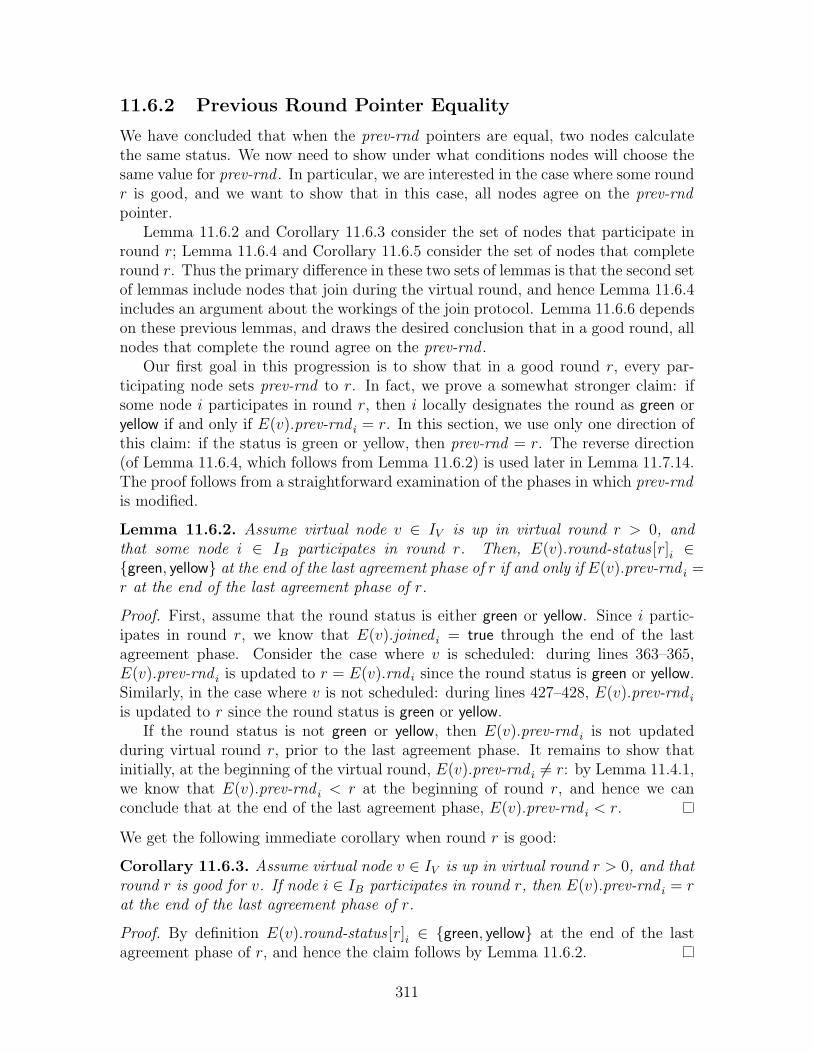
11.6.2 Previous Round Pointer Equality
We have concluded that when the prev-rnd pointers are equal, two nodes calculatethe same status. We now need to show under what conditions nodes will choose thesame value for prev-rnd . In particular, we are interested in the case where some roundr is good, and we want to show that in this case, all nodes agree on the prev-rndpointer.
Lemma 11.6.2 and Corollary 11.6.3 consider the set of nodes that participate inround r; Lemma 11.6.4 and Corollary 11.6.5 consider the set of nodes that completeround r. Thus the primary difference in these two sets of lemmas is that the second setof lemmas include nodes that join during the virtual round, and hence Lemma 11.6.4includes an argument about the workings of the join protocol. Lemma 11.6.6 dependson these previous lemmas, and draws the desired conclusion that in a good round, allnodes that complete the round agree on the prev-rnd .
Our first goal in this progression is to show that in a good round r, every par-ticipating node sets prev-rnd to r. In fact, we prove a somewhat stronger claim: ifsome node i participates in round r, then i locally designates the round as green oryellow if and only if E(v).prev-rnd i = r. In this section, we use only one direction ofthis claim: if the status is green or yellow, then prev-rnd = r. The reverse direction(of Lemma 11.6.4, which follows from Lemma 11.6.2) is used later in Lemma 11.7.14.The proof follows from a straightforward examination of the phases in which prev-rndis modified.
Lemma 11.6.2. Assume virtual node v ∈ IV is up in virtual round r > 0, andthat some node i ∈ IB participates in round r. Then, E(v).round-status [r ]i ∈{green, yellow} at the end of the last agreement phase of r if and only if E(v).prev-rnd i =r at the end of the last agreement phase of r.
Proof. First, assume that the round status is either green or yellow. Since i partic-ipates in round r, we know that E(v).joined i = true through the end of the lastagreement phase. Consider the case where v is scheduled: during lines 363–365,E(v).prev-rnd i is updated to r = E(v).rnd i since the round status is green or yellow.Similarly, in the case where v is not scheduled: during lines 427–428, E(v).prev-rnd i
is updated to r since the round status is green or yellow.If the round status is not green or yellow, then E(v).prev-rnd i is not updated
during virtual round r, prior to the last agreement phase. It remains to show thatinitially, at the beginning of the virtual round, E(v).prev-rnd i 6= r: by Lemma 11.4.1,we know that E(v).prev-rnd i < r at the beginning of round r, and hence we canconclude that at the end of the last agreement phase, E(v).prev-rnd i < r.
We get the following immediate corollary when round r is good:
Corollary 11.6.3. Assume virtual node v ∈ IV is up in virtual round r > 0, and thatround r is good for v. If node i ∈ IB participates in round r, then E(v).prev-rnd i = rat the end of the last agreement phase of r.
Proof. By definition E(v).round-status [r ]i ∈ {green, yellow} at the end of the lastagreement phase of r, and hence the claim follows by Lemma 11.6.2.
311

The previous lemma and corollary describe the behavior of nodes that participatein some virtual round r. We will be interested, however, not just in nodes that partic-ipate in a virtual round, but also those that complete the virtual round. Specifically,some nodes may join the emulation during a virtual round, and the same guaranteesneed hold at the end of the virtual round. Thus, we next show that at the end ofevery good round, every node that completes the round has set prev-rnd to the cur-rent round (Corollary 11.6.5). As before, we begin with a somewhat stronger lemma,Lemma 11.6.4. Notice that these two lemmas essentially extend Lemma 11.6.2 andCorollary 11.6.3 by including an argument that the join protocol works as expected.
Lemma 11.6.4. Assume virtual node v ∈ IV is up in virtual round r > 0, and thatsome node i ∈ IB completes round r. Then E(v).round-status [r ]i ∈ {green, yellow} atthe end of round r if and only if E(v).prev-rnd i = r at the end of r.
Proof. Since E(v).joined i = true at the end of virtual round r, there are two possiblebehaviors of node i, both of which can occur: node i participates in v in round r,and/or i joins v in r. (By assumption, i does not reset v in r2, as v is up in round r2.)
Assume i joins v in virtual round r. Then in the join-ack phase, node i re-ceives a message from some node k which includes a copy of E(v).prev-rndk andE(v).round-status [r ]k at the beginning of the join-ack phase. Since k has E(v).joinedk =true and E(v).failedk = false at the beginning of the join-ack phase, we can con-clude that k participates in round r, that is, k has joined and not failed from thebeginning of virtual round r through the end of the last agreement phase. ByLemma 11.6.2, we can conclude that E(v).round-status [r ]k is green or yellow if andonly if E(v).prev-rndk = r. Since both of these values are copied by i, the claim holdsfor i at the end of round r.
Assume i does not join virtual node v in virtual round r. Then we can concludethat i participates in virtual round r. By Lemma 11.6.2, we can conclude directlythat E(v).round-status [r ]i is green or yellow at the end of the last agreement phaseof r if and only if E(v).prev-rnd i = r at the end of the last agreement phase. Theonly way that round-status [r ] and prev-rnd change after the last agreement phase,prior to the end of the virtual round, is if i joins or resets v, which we have assumeddoes not occur in this case. Thus, we can conclude that the claim holds for i at theend of virtual round r.
We get the following immediate corollary when round r is good:
Corollary 11.6.5. If virtual node v ∈ IV is up in virtual round r > 0 and round r is agood round for v, then for every node i ∈ IB that completes round r, E(v).prev-rnd i =r at the end of r.
Proof. Choose r1 such that 〈r1, r〉 delineates a (finite) epoch of v. Since round r isgood, we conclude by Lemma 11.5.4 that E(v).round-status [r ]i ∈ {green, yellow} atthe end of virtual round r. We therefore conclude by Lemma 11.6.4 that E(v).prev-rnd i =r at the end of virtual round r
Finally, it follows immediately from Corollary 11.6.5 that any two nodes thatcomplete a good round have the same value for prev-rnd :
312

Lemma 11.6.6. If virtual round r > 0 is a good round, then for every pair of nodesi, j ∈ IB that complete round r for virtual node v, E(v).prev-rnd i = E(v).prev-rnd j
at the end of virtual round r.
Proof. For node i, we can conclude by Corollary 11.6.5 that E(v).prev-rnd i = r atthe end of r. Similarly for j, by Corollary 11.6.5, E(v).prev-rnd j = r at the end of r,leading to the desired conclusion.
11.6.3 Two Conclusions: Calculating the Status
Combining the main lemmas of this section, we can conclude that at the end of anygood virtual round, any two nodes that complete the virtual round calculate the samestatus:
Corollary 11.6.7. Assume 〈r1, r2〉 delineates a finite epoch of virtual node v. Ifround r2 is a good round, then for every pair of nodes i, j ∈ IB that complete roundr2 for v, if:
• status1 = calculate-status ( E(v).rnd i ,E(v).prev-rnd i ,E(v).ballot i ,E(v).round-status i ,E(v).last-reset i ) ,
• status2 = calculate-status ( E(v).rnd j ,E(v).prev-rnd j ,E(v).ballot j ,E(v).round-statusj ,E(v).last-reset j ) .
Then for every r ∈ [r1, r2], status [r]1 = status [r]2.
Proof. Follows immediately from Lemmas 11.6.1 and 11.6.6.
The second conclusion in this section is that the calculate-status function respectsthe fact that red rounds are, in fact, red. As mentioned earlier, it is important tonotice that a round is red based on a global condition, while calculate-status performsa local calculation.
A related fact is that the calculate-status function does not take the round-statusarray as a parameter; it infers all the relevant color information directly from the ballotdata structure instead. The round-status array is entirely local: each node calculatesits round status independently of the other nodes. The ballot data structure, on theother hand, contains information that is shared: a proposer broadcasts a ballot thatis then stored in each node’s ballot data structure. Thus, the calculate-state functionuses the data in the ballot data structure, rather than the local round status array,in order to approximate a global condition, i.e., whether the round is red or green.
Another relevant fact about this lemma is that it describes the result of a calcula-tion about some round r′ not only at the end of round r′, but also at the end of some
313

later round r2, assuming the virtual node is not reset between rounds r′ and r2. Thisfact, however, should be unsurprising, given the already-discussed persistence of theround color designation (e.g., Lemma 11.5.5).
Lemma 11.6.8. Assume 〈r1, r2〉 delineates a finite epoch of virtual node v, and icompletes virtual round r2. If r′ ∈ [r1, r2] is a red round for v, and at the end ofround r2:
• statusi = calculate-status ( E(v).rnd i ,E(v).prev-rnd i ,E(v).ballot i ,E(v).last-reset i ) ,
then status [r′] = red.
Proof. The proof follows from the way in which calculate-status uses the prev-rndpointers in the ballot. In each iteration of the loop, either the previous round pointerp is left unchanged, or it is updated as follows:
p ← ballot [p].prev-rnd .
Since ballot [p].prev-rnd is always a non-red round (by Lemma 11.5.12), we can con-clude that round p is always a non-red round. Moreover, in each iteration, status [r]is set to green if r = p and to red otherwise. Thus if status [r] is green, then the roundis non-red, proving the contrapositive of the desired lemma.
We now proceed in more detail. Assume for the sake of contradiction thatstatus [r′] = green. (Notice in calculate-status, the returned array contains only redand green colors.) Moreover, status [r′] = green only if temp-status [r′] = green at theend of the calculation; temp-status [r′] is set to green only if at some point during thecalculation p = r′. We therefore show that the following invariant holds throughoutthe calculate-status calculation: the virtual round p is not red. This claim impliesthat at no point during the calculation does p = r′, which results in a contradiction,proving the lemma.
Initially, the invariant holds since p is set to temp-prev , which is equal to E(v).prev-rnd i
at the end of round r2; by Lemma 11.5.11, we can conclude that p is not a redround. Inductively, in each iteration of the loop, if p = r, then p is set equal totemp-ballot [r].prev-rnd . By Lemma 11.5.12, we know that round E(v).ballot [r ].prev-rnd i,at the end of round r2, is not a red round, from which we conclude that the invariantholds, which concludes the proof.
11.7 Virtual Node Executions
In this section, we begin the process of constructing executions of virtual nodes. Asdescribed at the beginning of Section 11.6, our goal is to extract from α the possibleexecutions of each virtual node. In this section, for every 〈r1, r2〉 that delineates afinite epoch for virtual node v, we define the set execs(rr, r2)v of possible executions
314

(Definition 11.7.7). Each node that completes a virtual round may have its own localview of the virtual node’s execution; the set execs(r1, r2)v contains the local viewsof all nodes that complete virtual round r2. When there is only one execution inexecs(r1, r2)v, i.e., when |execs(r1, r2)v| = 1, then all the nodes have converged on asingle execution for v.
We begin in Section 11.7.1 with some preliminaries. We define an [r1, r2]-executionfragment (Definition 11.7.1), and a [r1, r2]-execution (Definition 11.7.2). An “execu-tion” is a well-defined TIOA concept; an [r1, r2]-execution is simply an executionthat runs from round r1 through the end of round r2. We then examine how toconstruct such an execution. Specifically, the functions do-bcast and do-recv (see Fig-ure 10-12) together construct a one round execution, which we prove in Lemma 11.7.3.Thus, when called repeatedly, they can construct a [r1, r2]-execution, as is implied byLemma 11.7.5.
In Section 11.7.2, we define a function execv : N × N × IB → executions of v.Specifically, if 〈r1, r2〉 delineates a finite epoch of virtual node v, and i ∈ IB, thenexec(r1, r2, i)v returns an [r1, r2] execution of virtual node v that is consistent with i’slocal view at the end of round r2. We show in Lemma 11.7.10 that exec(r1, r2, i)v isin fact an [r1, r2]-execution. We also define (Definition 11.7.7) the set execs(r1, r2)v,which is the set of all exec(r1, r2, i)v, for all i ∈ IB that complete round r2.
In the rest of Section 11.7, we present various properties of these constructedexecutions. In Section 11.7.3, we examine the case where a round is good. We showthat after a good round for virtual node v, every node participating in the emulationhas the same local view of virtual node v’s execution (Lemma 11.7.11). That is,exec(r1, r2, i)v = exec(r1, r2, j)v, for all i and j that complete round r2. This impliesthat |execs(r1, r2)v| = 1 (Corollary 11.7.12).
In later sections of this chapter (e.g., Sections 11.11 and 11.12) we prove a varietyof properties about these executions. For example, along with the client executions,they satisfy integrity, collision detector completeness, and collision detector eventualaccuracy. In Section 11.7.4, we prove one simple property about the constructed exe-cutions: they each satisfy the self-delivery property. That is, if a round r bcast(m, ·)v,∗event occurs in exec(r1, r2, i)v, then message m is received on port 〈v, ∗〉 in round r.
In Section 11.7.5, we prove a series of lemmas regarding these executions and theirextensions. Our eventual goal is to construct a single execution of virtual node v viasuccessive extension. Thus, in an ideal situation, exec(r1, r2, i)v would be a one-roundextension of exec(r1, r2 − 1, i)v, which itself would extend exec(r1, r2 − 2, i)v, and soon. In this way, we could construct an entire execution by calling exec repeatedlyto determine the next round. Unfortunately, the emulator cannot guarantee thisdesired behavior. For example, i may join the emulation in some round r > r1, andthus exec(r1, r, i)v cannot extend exec(r1, r−1, i)v. Alternatively, different nodes maydisagree in their local view of virtual node v’s execution; in order for the executionsto converge to a single execution, it may be necessary for some emulators to adoptother emulators’ executions.
In Section 11.7.5, then, we prove the following key claim: if 〈r1, r2〉 delineates afinite epoch of virtual node v, and if r2 > r1, then for every i ∈ IB, there exists somej ∈ IB that completes round r2−1 such that exec(r1, r2, i)v extends exec(r1, r2−1, j)v.
315

That is, after round r2, node i’s view of virtual node v’s execution is a one roundextension of some node j’s view of virtual node v’s execution after round r2 − 1.We prove this claim in two steps, first considering good rounds (Corollary 11.7.15),and then considering bad rounds (Corollary 11.7.18), before rearching the desiredconclusion in Lemma 11.7.19. This argument is applied inductively in Lemma 11.7.20to generate multi-round execution extensions.
Finally, in Lemma 11.7.21, we return to considering the behavior of good rounds,combining Lemma 11.7.19 and Corollary 11.7.15 to show that if a round r is goodand if node i is the round r proposer, then every node extends node i’s view of virtualnode v’s execution up through round r. Thus, in a good round, the proposer fixesthe virtual node’s execution up through round r.
11.7.1 Preliminaries
We begin by defining an [r1, r2]-execution fragment. Recall from Appendix A thatan execution fragment of a TIOA is a (finite or infinite) alternating sequence oftrajectories and actions with certain properties: it begins with a trajectory τ0, eachtrajectory τi is a trajectory of the TIOA, and the state at the beginning of each τi,i > 0, reflects the state at the end of τi−1 and the intervening action. An executionis simply an execution fragment that begins with an initial state of the TIOA.
We define an [r1, r2]-execution fragment to be an execution fragment of virtualnode v for rounds [r1, r2]. We place two restrictions on the execution fragment: (1)It must end with a recv event, since the last event in a virtual round is a recv;and (2) For every virtual round that is included in the execution fragment, there isexactly one recv event for v, since each virtual round in an execution includes one recvevent. (Notice that we do not need to place any restrictions on bcast events since thedefinition of a process, Definition 8.1.2, ensures that each non-terminal recv event isfollows by a bcast event.)
Definition 11.7.1. Let r1, r2 ∈ N, r2 ≥ r1. We define an [r1, r2]-execution frag-ment γ of virtual node v to be an execution fragment of the automaton Remap(AV (v), v)with starting time (r1 − 1) · RndLengthV with the following properties:
1. The last event in γ is a round r2 receive event for v.
2. For every r ∈ [r1, r2], γ contains exactly one round r recv for virtual node v,and no other recv events.
Notice that our definition of an [r1, r2]-execution fragment of v does not specifywhether a round r1 broadcast occurs. (For all rounds r : r1 < r < r2, a round r bcastevent is required, since every execution of a process has a bcast immediately followingevery recv event.) We say that a [r1, r2]-execution fragment is broadcast completeif it includes a round r1 broadcast, and broadcast incomplete otherwise. Everyexecution of a process begins with a broadcast incomplete round: a trace of a processalways begins with a recv event (i.e., a dummy message), as it broadcasts a messageonly in response to receiving a message from the previous round. (See Section 8.1.5for an explanation of how the broadcast service drives the round structure.)
316

Thus, an [r1, r2]-execution of v is an [r1, r2]-execution fragment that begins in thevirtual node’s initial state, startv and that has no round r1 bcast event.
Definition 11.7.2. Let r1, r2 ∈ N, r2 ≥ r1. An [r1, r2]-execution γ of virtual node vis a broadcast incomplete [r1, r2]-execution fragment of v in which fstate(γ) = startv.
Throughout the rest of this section, we will be constructing [r1, r2]-executions.The basic algorithm we use for constructing these executions is to repeatedly call thefunctions do-bcastv and do-recvv (see Figure 10-12). The function do-bcastv insertsa bcastv,∗ event, while the function do-recvv inserts a single round of time passage,followed by a recvv,∗ event. Together, these two functions construct a one round,broadcast-complete execution fragment for virtual node v:
Lemma 11.7.3. If s ∈ statesv is a state of virtual node v ∈ IV such that s is the laststate of an execution, γ, which has a recv event as its last action, and if:
• 〈s′, m, r, e1〉 ← do-bcast(s)
• 〈s′′, e2〉 ← do-recv(s′, M, cd , cm) .
Then for every r > 0, e1.e2 is a broadcast-complete [r, r]-execution fragment of v ands′′ is the last state of e2, i.e., the state of the virtual node at the end of round r.
Proof. The lemma follows immediately by inspection. Notice that do-bcast simulatesvirtual node v broadcasting a message, after some number of internal actions. Sim-ilarly, do-recv simulates one round of time passage (including any internal actions),followed by v receiving a set of messages. Notice also that both functions terminate,producing a finite execution, as per Lemmas 10.3.1 and 10.3.2. Thus the criteria fora [r, r]-execution fragment are met.
Along the same lines, the do-recv function constructs a one round broadcast-incompleteexecution of a virtual node:
Lemma 11.7.4. If s ∈ statesv is a state of virtual node v ∈ IV such that s is the laststate of an execution, γ, which does not end in a recv event, and if:
• 〈s′, e〉 ← do-recv(s, ·, ··) .
Then for every r > 0, e is a broadcast-incomplete [r, r]-execution fragment of v ands′ is the last state of e, i.e., the state of the virtual node at the end of round r.
Proof. As in the Lemma 11.7.3, the lemma follows immediately by inspection. Noticethat do-recv simulates one round of time passage (including any internal actions),followed by v receiving a set of messages. Thus the criteria for a broadcast-incomplete[r, r]-execution fragment are met.
We can thus conclude from Lemma 11.7.4 that if s = startv, the initial state of v,then do-recv constructs a one round execution of v.
Next, notice that by concatenating executions and execution fragments, we canconstruct longer executions:
317
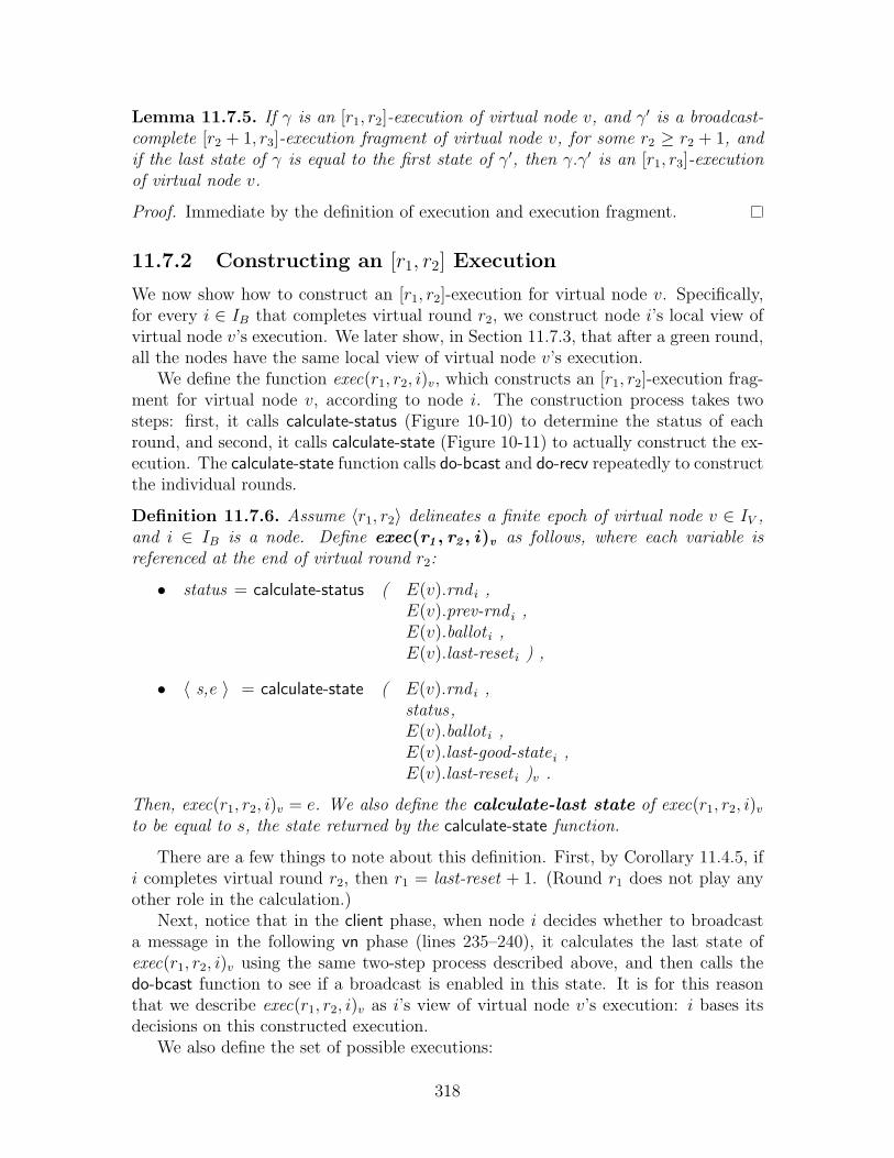
Lemma 11.7.5. If γ is an [r1, r2]-execution of virtual node v, and γ′ is a broadcast-complete [r2 + 1, r3]-execution fragment of virtual node v, for some r2 ≥ r2 + 1, andif the last state of γ is equal to the first state of γ′, then γ.γ′ is an [r1, r3]-executionof virtual node v.
Proof. Immediate by the definition of execution and execution fragment.
11.7.2 Constructing an [r1, r2] Execution
We now show how to construct an [r1, r2]-execution for virtual node v. Specifically,for every i ∈ IB that completes virtual round r2, we construct node i’s local view ofvirtual node v’s execution. We later show, in Section 11.7.3, that after a green round,all the nodes have the same local view of virtual node v’s execution.
We define the function exec(r1, r2, i)v, which constructs an [r1, r2]-execution frag-ment for virtual node v, according to node i. The construction process takes twosteps: first, it calls calculate-status (Figure 10-10) to determine the status of eachround, and second, it calls calculate-state (Figure 10-11) to actually construct the ex-ecution. The calculate-state function calls do-bcast and do-recv repeatedly to constructthe individual rounds.
Definition 11.7.6. Assume 〈r1, r2〉 delineates a finite epoch of virtual node v ∈ IV ,and i ∈ IB is a node. Define exec(r1 , r2 , i)v as follows, where each variable isreferenced at the end of virtual round r2:
• status = calculate-status ( E(v).rnd i ,E(v).prev-rnd i ,E(v).ballot i ,E(v).last-reset i ) ,
• 〈 s,e 〉 = calculate-state ( E(v).rnd i ,status,E(v).ballot i ,E(v).last-good-state i ,E(v).last-reset i )v .
Then, exec(r1, r2, i)v = e. We also define the calculate-last state of exec(r1, r2, i)v
to be equal to s, the state returned by the calculate-state function.
There are a few things to note about this definition. First, by Corollary 11.4.5, ifi completes virtual round r2, then r1 = last-reset + 1. (Round r1 does not play anyother role in the calculation.)
Next, notice that in the client phase, when node i decides whether to broadcasta message in the following vn phase (lines 235–240), it calculates the last state ofexec(r1, r2, i)v using the same two-step process described above, and then calls thedo-bcast function to see if a broadcast is enabled in this state. It is for this reasonthat we describe exec(r1, r2, i)v as i’s view of virtual node v’s execution: i bases itsdecisions on this constructed execution.
We also define the set of possible executions:
318
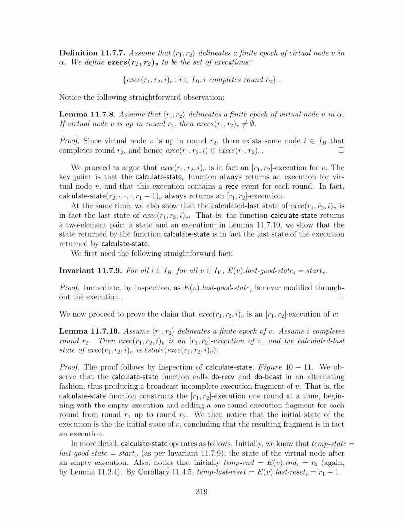
Definition 11.7.7. Assume that 〈r1, r2〉 delineates a finite epoch of virtual node v inα. We define execs(r1 , r2)v to be the set of executions:
{exec(r1, r2, i)v : i ∈ IB, i completes round r2} .
Notice the following straightforward observation:
Lemma 11.7.8. Assume that 〈r1, r2〉 delineates a finite epoch of virtual node v in α.If virtual node v is up in round r2, then execs(r1, r2)v 6= ∅.
Proof. Since virtual node v is up in round r2, there exists some node i ∈ IB thatcompletes round r2, and hence exec(r1, r2, i) ∈ execs(r1, r2)v.
We proceed to argue that exec(r1, r2, i)v is in fact an [r1, r2]-execution for v. Thekey point is that the calculate-statev function always returns an execution for vir-tual node v, and that this execution contains a recv event for each round. In fact,calculate-state(r2, ·, ·, ·, r1 − 1)v always returns an [r1, r2]-execution.
At the same time, we also show that the calculated-last state of exec(r1, r2, i)v isin fact the last state of exec(r1, r2, i)v. That is, the function calculate-state returnsa two-element pair: a state and an execution; in Lemma 11.7.10, we show that thestate returned by the function calculate-state is in fact the last state of the executionreturned by calculate-state.
We first need the following straightforward fact:
Invariant 11.7.9. For all i ∈ IB, for all v ∈ IV , E(v).last-good-state i = startv.
Proof. Immediate, by inspection, as E(v).last-good-state i is never modified through-out the execution.
We now proceed to prove the claim that exec(r1, r2, i)v is an [r1, r2]-execution of v:
Lemma 11.7.10. Assume 〈r1, r2〉 delineates a finite epoch of v. Assume i completesround r2. Then exec(r1, r2, i)v is an [r1, r2]-execution of v, and the calculated-laststate of exec(r1, r2, i)v is `state(exec(r1, r2, i)v).
Proof. The proof follows by inspection of calculate-state, Figure 10 − 11. We ob-serve that the calculate-state function calls do-recv and do-bcast in an alternatingfashion, thus producing a broadcast-incomplete execution fragment of v. That is, thecalculate-state function constructs the [r1, r2]-execution one round at a time, begin-ning with the empty execution and adding a one round execution fragment for eachround from round r1 up to round r2. We then notice that the initial state of theexecution is the the initial state of v, concluding that the resulting fragment is in factan execution.
In more detail, calculate-state operates as follows. Initially, we know that temp-state =last-good-state = startv (as per Invariant 11.7.9), the state of the virtual node afteran empty execution. Also, notice that initially temp-rnd = E(v).rnd i = r2 (again,by Lemma 11.2.4). By Corollary 11.4.5, temp-last-reset = E(v).last-reset i = r1 − 1.
319

calculate-state begins by constructing a round [r1, r1]-execution by calling do-recv,as per Lemma 11.7.4, where temp-state is the initial state of v. It proceeds iterativelyfrom r = r1+1 up to r = r2. At each step, exec maintains the inductively constructedexecution, and temp-state maintains the last state of exec.
For each r ∈ [r1 + 1, r2], the protocol constructs a [r, r]-execution fragment forv, beginning in the last state of the inductively constructed execution, temp-state.calculate-state invokes do-bcast, followed by do-recv, creating a broadcast-completeexecution fragment, as per Lemma 11.7.3. (At each step, the last event in the in-ductively constructed execution is a recv event.) This fragment is then appendedto the inductively constructed execution, as per Lemma 11.7.5. When r = r2, theconstruction is complete. It follows immediately that temp-state is the last state ofthe execution exec, as required.
Finally, notice that the initial state of exec = startv, the initial state of v, andhence the fragment exec is an execution.
11.7.3 Only One Good [r1, r2]-Execution
In this section, we show a result that is important in proving that the agreement pro-tocols converge to a single execution when the system is “well-behaved.” Specifically,we show that in a good round r, every node that completes round r calculates thesame execution.
Lemma 11.7.11. Assume 〈r1, r2〉 delineates a finite epoch of virtual node v. If roundr2 is a good round, then for every pair i, j ∈ IB that complete round r2 for virtualnode v: exec(r1, r2, i) = exec(r1, r2, j).
Proof. Each exec is calculated in a two-step process by first calling calculate-statusto determine status i and statusj, and then by calling calculate-state. We arguethat the input parameters to calculate-state are identical, with only one exception:E(v).ballot [r ]i and E(v).ballot [r ]j can differ in red rounds. We argue that thecalculate-status function does not examine the ballot array for red rounds, and hencethe calculations proceed identically despite this difference.
In more detail, consider the parameters to calculate-state:
• temp-rnd : By Corollary 11.2.6, temp-rnd i = temp-rnd j.
• temp-status : By Corollary 11.6.7, for every r ∈ [r1, r2], temp-status [r]i =temp-status [r]j. The calculate-state function does not access the temp-statusarray outside this range.
• temp-ballot : For r ∈ [r1, r2], if temp-status [r]i = green, then temp-ballot [r]i =temp-ballot [r]j. This claim follows because if temp-status [r]i = green, then weknow by the contrapositive of Lemma 11.6.8 that virtual round r is not red; byCorollary 11.5.20, we know that if virtual round r is not red, then the ballotarrays are equal.
320

• temp-last-reset : By Corollary 11.4.5, temp-last-reset i = temp-last-reset j = r1−1.
• temp-state: By Invariant 11.7.9, temp-state i = temp-statej = startv.
We conclude the proof by noticing that the calculate-state function only accessestemp-ballot [r], for some r > 0, if temp-status [r] = green (see line 545, Figure 10-11).Thus the two calculations proceed identically, and produce the same execution, asdesired.
We get the following immediate corollary, restating Lemma 11.7.11 in terms ofthe set execs :
Corollary 11.7.12. Assume that 〈r1, r2〉 delineates a finite epoch of virtual node v,and round r2 is green for v. Then |execs(r1, r2)v| = 1.
Proof. By Corollary 11.5.7, we know that round r2 is a good round. By Lemma 11.7.11,if i and j are participating in round r2 and round r2 is good, then exec(r1, r2, i) =exec(r1, r2, j), concluding the proof.
11.7.4 Message Self-Delivery
Later in Sections 11.11 and 11.12, we prove a variety of properties of the executionswe have constructed. These later properties, however, involve interactions amongdifferent virtual nodes and clients. Here we prove one simple property involving anindividual virtual node: each execution satisfies the self-delivery property. That is,if a virtual node v broadcasts a message m in a virtual round r, then it also receivesmessage m in round r.
Lemma 11.7.13. Assume that 〈r1, r2〉 delineates a finite epoch of virtual node v ∈ IV .Assume γ ∈ execs(r1, r2)v. If for some m ∈ msgsV , a round r2 bcast(m, ·)v,∗ occursin γ, then a round r2 recv(M, . . .)v,∗ event occurs in γ in which m ∈M .
Proof. This lemma follows immediately from the calculate-state function. Fix i suchthat γ = exec(r1, r2, i), which is calculated by calling calculate-state at the end ofround r2. Notice that if a bcast event occurs in γ, it is added by a call to do-bcast ineither line 554 or line 564. In both cases, the do-bcast function returns the messagebroadcast, temp-msg . When constructing round r2, temp-msg = m. In both cases,the temp-msg message is added to the inM set, which is then used as a parameter todo-recv, thus ensures that m is in the set of messages received.
11.7.5 Every Execution Extends an Earlier Execution
A key property of an execution exec(r1, r2, i)v is that if r2 > r1 and if i completesround r2, then we can conclude that exec(r1, r2, i)v extends execution exec(r1, r2 −1, j)v, for some j that completes round r2 − 1. As a result of this property, we can
321

construction executions of v through successive extension: if we take a sequence ofsets of executions:
〈execs(r1, r1)v, execs(r1, r1 + 1)v, . . . , execs(r1, r2)v〉 ,
then we can conclude that every execution γ ∈ execs(r1, r2)v has a prefix in each ofthe sets in the sequence.
In this section, we prove two slightly stronger lemmas that identify exactly whichexecution is extended, based on the color that i designates for round r2. We thenconclude with the main result of this section, Lemma 11.7.19, which shows the keyproperty described above.
First, we consider the case where a node j ∈ IB designates round r2 to be eithergreen or yellow. As a result, we can conclude that round r2 is not a red round, andhence has a unique proposer (Corollary 11.5.15), which we designate i. In this case,we claim that the execution constructed by node j is an extension of the executionconstructed by node i.
Lemma 11.7.14. Assume that 〈r1, r2〉 delineates a finite epoch of virtual node v ∈ IV
and that r2 > r1. Assume j ∈ IB completes round r2 and has E(v).round-status [r ]j ∈{green, yellow} at the end of r2. Moreover, assume that node i ∈ IB is the round r2
proposer. (See Definition 11.5.17; as result of the existence of i we know that suchan i exists.) Then exec(r1, r2, j)v is a one-round extension of exec(r1, r2 − 1, i).
Proof. Let γi = exec(r1, r2 − 1, i) and γj = exec(r1, r2, j). Our goal is to showthat γi is a prefix of γj. The proof proceeds in three parts. First, we recall theconstruction of γi and γj via the calculate-status and calculate-state functions. Second,we examine the calculate-status function and claim that i and j calculate the sameround status for each of the rounds in the range [r1, r2 − 1]. This second part ofthe proof closely resembles the proof for Lemma 11.6.1. Third, we examine thecalculate-state function and claim that as a result, both constructions produce thesame execution prefix from round r1 through round r2 − 1. The main fact used hereis that the invocations to calculate-state differ (primarily) in the ballot data structure;however calculate-state examines the round r ballot [r] only when round r is not red,and hence by Corollary 11.5.18, the ballots for i and j are equal.
Part 1: Recall the construction of γi and γj. The two executions γi and γj areeach constructed in two steps: first by calling calculate-status, and then by callingcalculate-state. Specifically, for γi = exec(r1, r2 − 1, i):
• status i =calculate-status ( E(v).rnd i − 1,E(v).prev-rnd i,E(v).ballot i,E(v).last-reset i) ,
• 〈s, e〉 =calculate-state ( E(v).rnd i − 1,status i,E(v).ballot i,E(v).last-good-state i,E(v).last-reset i)v .
322
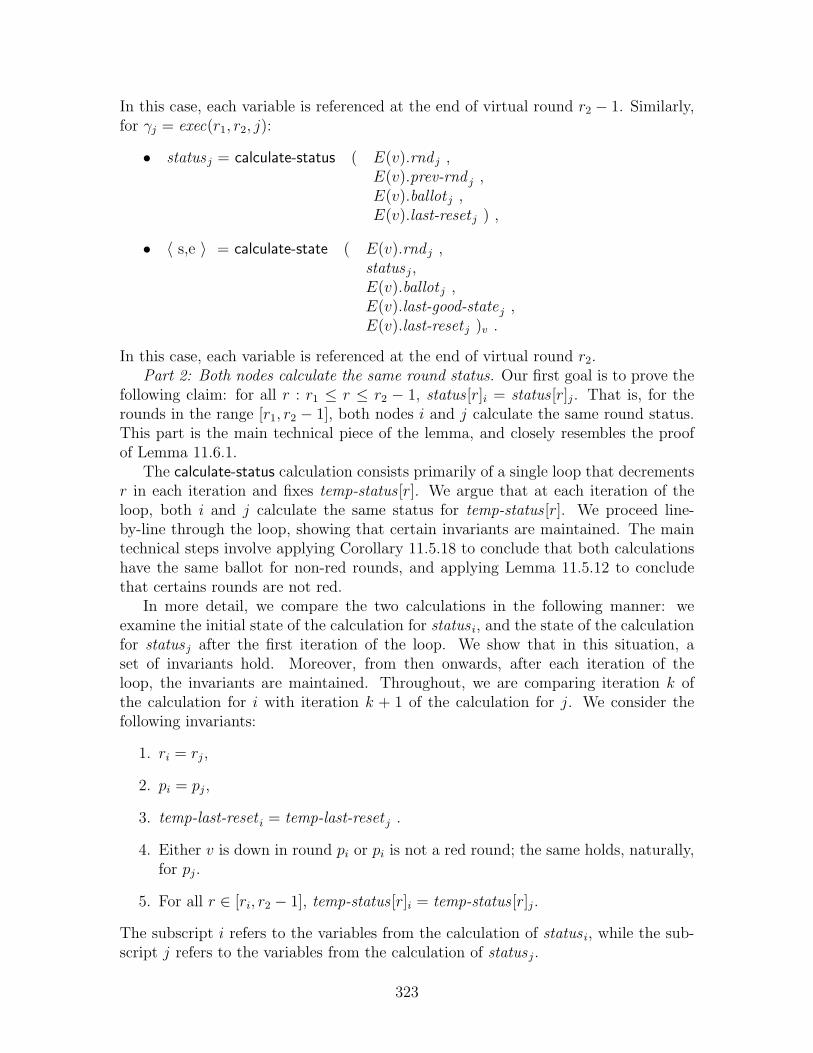
In this case, each variable is referenced at the end of virtual round r2 − 1. Similarly,for γj = exec(r1, r2, j):
• statusj = calculate-status ( E(v).rnd j ,E(v).prev-rnd j ,E(v).ballot j ,E(v).last-reset j ) ,
• 〈 s,e 〉 = calculate-state ( E(v).rnd j ,statusj,E(v).ballot j ,E(v).last-good-statej ,E(v).last-reset j )v .
In this case, each variable is referenced at the end of virtual round r2.Part 2: Both nodes calculate the same round status. Our first goal is to prove the
following claim: for all r : r1 ≤ r ≤ r2 − 1, status [r]i = status [r]j. That is, for therounds in the range [r1, r2 − 1], both nodes i and j calculate the same round status.This part is the main technical piece of the lemma, and closely resembles the proofof Lemma 11.6.1.
The calculate-status calculation consists primarily of a single loop that decrementsr in each iteration and fixes temp-status [r]. We argue that at each iteration of theloop, both i and j calculate the same status for temp-status [r]. We proceed line-by-line through the loop, showing that certain invariants are maintained. The maintechnical steps involve applying Corollary 11.5.18 to conclude that both calculationshave the same ballot for non-red rounds, and applying Lemma 11.5.12 to concludethat certains rounds are not red.
In more detail, we compare the two calculations in the following manner: weexamine the initial state of the calculation for status i, and the state of the calculationfor statusj after the first iteration of the loop. We show that in this situation, aset of invariants hold. Moreover, from then onwards, after each iteration of theloop, the invariants are maintained. Throughout, we are comparing iteration k ofthe calculation for i with iteration k + 1 of the calculation for j. We consider thefollowing invariants:
1. ri = rj,
2. pi = pj,
3. temp-last-reset i = temp-last-reset j .
4. Either v is down in round pi or pi is not a red round; the same holds, naturally,for pj.
5. For all r ∈ [ri, r2 − 1], temp-status [r]i = temp-status [r]j.
The subscript i refers to the variables from the calculation of status i, while the sub-script j refers to the variables from the calculation of statusj.
323

Consider the initial state of the status i calculation and the state of the statusj
calculation after the first iteration through the calculate-status loop:
1. Round r counter: Initially, ri = r2 = temp-rnd i +1 (by Lemma 11.2.4,as usual);after the first iteration rj = r2 (by Lemma 11.2.4), as rj has been decrementedonce from r2 + 1. Thus ri = rj.
2. Previous round pointer p: Initially, pi = E(v).prev-rnd i at the end of roundr2 − 1; we now argue that pj after the first iteration of the calculate-status loopis also equal to E(v).prev-rnd i at the end of round r2 − 1.
Initially, temp-prev j = temp-rnd j = r2 by Lemma 11.6.4, since round r2 is agood round. Thus initially, pj = r2. As discussed above, initially, rj = r2 + 1,and rj is immediately decremented to equal r2 (line 506, Figure 10-10). Next, inline 507, pj is compared to rj. Since pj = rj, the first branch of the if statementis executed, updating pj = ballot [r2].prev-rnd . It thus remains to show thatballot [r2].prev-rnd = pi.
Recall that i is the unique proposer of a ballot in round r2. (By Corollary 11.5.15we know that there is only one proposer since round r2 is good.) Thus the ballotwhich is broadcast in the ballot phase for v in r2 (whether it is scheduled orunscheduled) contains E(v).prev-rnd i at the beginning of virtual round r2, i.e.,the end of virtual round r2 − 1. Therefore, E(v).ballot [r2 ].prev-rnd j at the endof round r2 is equal to E(v).prev-rnd i at the beginning of round r2, by whichwe conclude that pi, initially, is equal to pj, after the first iteration of the loop.
3. Last good round temp-last-reset : In both calculation, temp-last-reset = r1 − 1both initially and throughout the calculation, as per Corollary 11.4.5.
4. Either v is down in round pi, or round pi is not red: By Lemma 11.5.11, eitherv is down in E(v).prev-rnd i or the round is not red, leading to the initial con-clusion about pi. Since after the first iteration, pj = pi initially, the claim holdsalso for pj.
5. Temporary status array temp-status : ri = r2 > r2−1, hence for all r ∈ [ri, r2−1],the claim about the status array is trivially true.
We argue that although the temp-ballot arrays may differ, in fact the calculationsproceed in an identical manner, and thus the invariants are maintained throughoutthe calculation. The argument is nearly identical to that from Lemma 11.6.1.
The first step of the loop is to decrement ri and rj. Thus, after the first step (andhence at the end of the loop), ri = rj, maintaining Invariant 1. We can also nowconclude that r1 ≤ ri ≤ r2 − 1, and thus v is up in round ri (and round rj).
Next, after ri and rj are decremented, the calculation branches, based on whetherri = pi, and whether rj = pj. Since ri = rj and pi = pj, both calculations proceedthrough the same branch of the if clause on line 507.
If they choose the first branch, both pi and pj are updated according to thetemp-ballot [pi].prev-rnd data structure. Since pi = ri, we can conclude that v is upin round pi, and hence that temp-ballot [pi] = temp-ballot [pj] by Corollary 11.5.18.
324

According to Lemma 11.5.12, if r = E(v).ballot [pi ].prev-rndk, then either round ris not a red round or v is down in round r; thus setting pi = r maintains Invariant 4on pi. Moreover, since prior to updating pi and pj, temp-ballot [pi] = temp-ballot [pj],we can conclude that after the update pi = pj at the end of the loop, maintainingInvariant 2.
The variable temp-last-reset is not modified in either case, and thus Invariant 3 ismaintained.
Finally, temp-statusi and temp-statusj are updated depending on the branch cho-sen in the loop; as argued above, both calculations choose the same branch in theloop, and hence temp-status [ri]i = temp-status [rj]j. By induction, we already knowthat for r ∈ [ri+1, r2−1], temp-status [r]i = temp-status [r]i; thus, we have maintainedInvariant 5.
Part 3: Examining calculate-state and the construction of γi and γj. We can nowconclude the proof by examining the calculate-state function. Specifically, we want toexamine the two executions γi and γj constructed by the following:
• 〈·, γi〉 ← calculate-state(r2 − 1, status i, E(v).ballot i, r1 − 1, startv)v .
• 〈·, γj〉 ← calculate-state(r2, statusj, E(v).ballot j, r1 − 1, startv)v .
There are three ways in which these invocations differ. First, γi begins with temp-rnd i =r2 − 1, while γj begins with temp-rnd = r2. Since temp-rnd controls the num-ber of times the loop is repeated, this indicates that γj is one round longer thanγi. The second difference is in the status array: we have argued above that forall r : r1 ≤ r ≤ r2 − 1, status i = statusj; for round outside this range, the ar-ray may differ. Third, the temp-ballot arrays may differ. As before, if some vir-tual round r ∈ [r1, r2 − 1] is not red, then we know by Corollary 11.5.20 thattemp-ballot [r]i = temp-ballot [r]j. We argue that despite these differences, from roundr1 through round r2 − 1, both calculations constructs the same [r1, r2 − 1-execution,and hence γj is a one-round extension of γi.
In more detail, notice that the calculate-state function accesses the ballot ar-ray only when temp-status [r] = green. By Lemma 11.6.8, however, we know thattemp-status [r] is green only when virtual round r is not red, as temp-status is a resultof the calculate-status calculation. Thus, whenever the two calculations access theballot array, the value are the same.
Thus, in each iteration of the for loop, beginning with r = r1 and up until r =r2−1, the two invocations proceed in the same manner: first, calculating inCM basedon whether v is scheduled in round r; branching, based on whether temp-status [r] isgreen or red; if the status is green, they both construct a round based on the ballotdata structures, which are the same; if the status is red, they both construct a roundthat does not depend on the ballot data structure.
Thus, when r = r2 − 1, the two executions are the same. Execution γj goes on toappend an additional round, and so we conclude that γi is always a prefix of γj, asrequired.
We get the following immediate corollary when round r2 is good:
325

Corollary 11.7.15. Assume that 〈r1, r2〉 delineates a finite epoch of virtual nodev ∈ IV and that r2 > r1. If round r2 is good, and i ∈ IB is the round r2 proposer,then for every j ∈ IB that completes round r2, exec(r1, r2, j)v is an extension ofexec(r1, r2 − 1, i).
Proof. By Lemma 11.5.4, if round r2 is good, then E(v).round-status [r2 ]j ∈ {green, yellow},and the claim follows by Lemma 11.7.14.
We have just examined the case where a node j (locally) designates a round r tobe green or yellow, and the case where a round r is good. We now proceed to thecase where a node j (locally) designates a round to be orange or red, and the casewhere a round r is bad. Specifically, we want to show that for every j ∈ IB thatcompletes round r2, if j designates the round to be orange or red, then there existssome i ∈ IB where exec(r1, r2, j)v extends exec(r1, r2 − 1, i)v. (In the case where jlocally designated the round as green or yellow, i was the unique proposer.)
In order to prove this claim, we consider two cases separately: first, the case wherej does not join the virtual node in round r2, i.e., the case where j participates in roundr2 (Lemma 11.7.16); second, the case where j joins v in round r (Lemma 11.7.17). Inthis second case, we apply our previous analysis of the join protocol (Lemma 11.5.3)to show that the desired conclusion holds.
In the following lemma, we assume that a node j (locally) designates a roundas orange or red, and assume that j participates in round r2 and does not join theemulation of v in round r2. We then claim that node j extends its own round r2 − 1execution. That is, exec(r1, r2, j)v extends exec(r1, r2−1, j)v. This result is intuitivelywhat one might expect: in a bad round, it is not possible for j to extend any othernode’s execution of v, as communication has been unreliable; thus the only safepossibility is for j to extend j’s own execution of v.
Lemma 11.7.16. Assume that 〈r1, r2〉 delineates a finite epoch of virtual node v ∈ IV
and that r2 > r1. Moreover, assume that j ∈ IB participates in round r2 and doesnot join v in round r2. If E(v).round-status [r2 ]j ∈ {red, orange} at the end of the lastagreement phase, then execution exec(r1, r2, j)v extends execution exec(r1, r2 − 1, j)v.
Proof. Recall that each execution is calculated in two steps: first, determining theround status array (calculate-status), and second, constructing the actual execution(calculate-state). We are comparing two such calculations for node j at the end ofround r2 − 1 and the end of round r2. The main difficulty in the proof is showingthat the round status array for the two different calculations is the same for everyr ∈ [r1, r2 − 1]. In fact, since the round r2 was (locally) designated by j to be redor orange, we conclude that the E(v).prev-rnd j pointer was unmodified in roundr2, and as a result, the status calculation is also identical. As a result, the inputs tothe calculate-state calculation are identical (for rounds in the range [r1, r2 − 1]); forexample, for every round r ∈ [r1, r2− 1], ballot [r] is the same in both cases. Thus weconclude the the calculations proceed identically, leading to the desired result.
Let:
sA = calculate-status(E(v).rnd j, E(v).prev-rnd j, E(v).ballot j, E(v).last-reset j)
326

at the end of round r2 − 1, and let:
sB = calculate-status(E(v).rnd j, E(v).prev-rnd j, E(v).ballot j, E(v).last-reset j)
at the end of round r2. Notice that sA is the status array used in the calculation ofexec(r1, r2−1, j)v, while sB is the status array used in the calculation of exec(r1, r2, j)v.
Part 1: In the first part of the proof, we show the following: for all r ∈ [r1, r2−1],s[r]A = s[r]B. As in Lemma 11.7.14, we compare the initial state of the sA calculationto the state of the sB calculation after the first iteration of the loop. We claim thatin this situation, and after each subsequent iteration of the loop, the local statecalculated is equivalent:
1. rA = rB,
2. pA = pB,
3. temp-last-resetA = temp-last-resetB,
4. for r ∈ [r1, r2 − 1], temp-ballots [r]A = temp-ballots [r]B, and
5. for r ∈ [r1, r2 − 1], temp-status [r]A = temp-status [r]B.
First we compare the initial state of calculation sA to the state of sB after the firstiteration of the loop:
• Round r counter: Initially, rA = temp-rndA+1 = r2 (by Lemma 11.2.4,as usual).Initially, rB = temp-rndB + 1 = r2 + 1, and hence after the first iteration ofcalculation sB, rB = r2 (by Lemma 11.2.4), as rj has been decremented oncefrom r2 + 1. Thus rA = rB.
• Previous round pointer p: We first argue that E(v).prev-rnd j is not modifiedduring virtual round r2. Prior to the last agreement phase, E(v).prev-rnd j isnot modified, since since E(v).round-status [r2 ]j is red or orange. After the lastagreement phase, E(v).prev-rnd j is not modified, since j does not join or resetv in round r2. Thus, E(v).prev-rnd j is unchanged in virtual round r2. Fromthis we conclude that initially pA = pB.
Next, we argue that pB is not modified during the first iteration of the calcu-lation of sB. In particular, pB is only modified if rB = pB. Yet we have justargued that pB is not modified in virtual round r2; at the beginning of virtualround r2, pB < r2, by Lemma 11.4.1. Thus, pB 6= rB, and after the first iterationpB = pA initially.
• Last good round temp-last-reset : In both calculation, temp-last-reset = r1 − 1both initially and throughout the calculation, as per Corollary 11.4.5.
• Temporary status array temp-status : Initially, for all r ≤ r2, temp-status [r ]A =temp-status [r ]B = ⊥. In the first iteration, the statusB calculation updates onlytemp-status [r2]; thus for all r < r2, temp-status [r]j = ⊥.
327

• Temporary ballot array temp-ballot : During virtual round r2, for every r < r2,E(v).ballot [r ]j is unmodified: prior to the last agreement phase, this follows im-mediately; after the last agreement phase, this follows since j does not join orreset v. Thus, for every r ∈ [r1, r2− 1], E(v).ballot [r ]j is the same at the begin-ning and end of round r2, and hence initially, temp-ballot [r ]A = temp-ballot [r ]B.Moreover, temp-ballot [r] is never modified during the calculate-status calcula-tion, and hence they remain equal after the first iteration of the calculationof sB.
Since the initial state of calculation sA and the state of calculation sB after the firstiteration are equivalent, except for array values outside the range [r1, r2 − 1], andsince neither calculation accesses an array entry outside of the range [r1, r2 − 1], weconclude that the calculations proceed identically in both instances, and as a result,when the calculation terminates, for every r ∈ [r1, r2 − 1], s [r]A = s [r]B.
Part 2: The proof concludes by examining the calculate-state function. All theinput parameters are equal in the two calculations, with the following exceptions: (1)array entries outside the range [r1, r2− 1], and (2) initially, temp-stateA = r2− 1 andtemp-stateB = r2. Both calculations thus execute the same for loop, beginning atround r1, and proceeding to construct the execution round by round. Since the ballotand status array entries are the same, the execution constructed is the same, throughthe end of round r2 − 1. At this point, the calcuation of exec(r1, r2 − 1, j)v returns,while the calculation of exec(r1, r2, j)v continues, ensuring that the former is a prefixof the latter.
In Lemma 11.7.16, we assume that node j does not join virtual node v in roundr2. We now consider the more general case where j may join virtual node in roundr2; our only assumption about node j is that it completes round r2. If node j joinsthe emulation in round r2, we can no longer conclude that j extends its own priorexecution for v, as j has no prior execution to extend! Instead, we argue that jextends the execution of some other node i, specifically, the node i that sent thejoin-ack message that allowed j to complete the join protocol.
Lemma 11.7.17. Assume that 〈r1, r2〉 delineates a finite epoch of virtual node v ∈ IV
and that r2 > r1. Moreover, assume that j ∈ IB completes round r2. If E(v).ballot [r2 ]j ∈{red, orange}, then there exists some i ∈ IB that participates in virtual round r2 suchthat execution exec(r1, r2, j)v extends execution exec(r1, r2 − 1, i)v.
Proof. If j does not join v in round r2, then the conclusion follows immediately fromLemma 11.7.16: in this case, j participates in round r2, and hence we choose i = j.Thus it remains to consider the case where j joins v in round r2.
If j joins v in round r2, then j receives a message from some node i ∈ IB duringthe join-ack phase. It is straightforward to see that i does not join v in round r2, asi sends information in the join-ack phase; similarly, it is clear that i participates inround r2. By Lemma 11.7.16, we conclude that exec(r1, r2−1, i)v at the end of roundr2 − 1 is a prefix of exec(r1, r2, i)v at the end of round r2.
328

After j joins, all the relevant state variables of j are equal to those of i. Thus theircalculation of the executions proceed identically, that is, exec(r1, r2, i)v = exec(r1, rj, j)v
at the end of round r2, which implies the desired result.
We get the following immediate corollary which states that when a round r2 is bad,then every calculated execution extends some previous execution:
Corollary 11.7.18. Assume that 〈r1, r2〉 delineates a finite epoch of virtual nodev ∈ IV and that r2 > r1. Moreover, assume that i ∈ IB completes round r2. If roundr2 is bad, then there exists some j ∈ IB that participates in virtual round r2 such thatexecution exec(r1, r2, i)v extends execution exec(r1, r2 − 1, j)v.
Proof. By Lemma 11.5.4, we know that E(v).round-status [r2 ]i is either red or orangeat the end of round r2, and the claim then follows by Lemma 11.7.17
The following lemma, then, is a key lemma which shows that every executionis an extension of a previous execution. Recall that Lemma 11.7.14 addresses thesituation where a node j ∈ IB designated a round to be green or yellow; Lemma 11.7.17addresses the situation where a node j ∈ IB desiganted a round to be orange orred. Thus the following lemma combines these two results, showing that regardlessof the color designation, if j completes round r2, then its view of virtual node v’s[r1, r2]-execution is a one-round extension of some other node’s view of v’s [r1, r2−1]-execution. Moreover, we argue that this other node does not fail or depart theemulation prior to the scheduled-ballot phase.
Lemma 11.7.19. Assume 〈r1, r2〉 delineates a finite epoch of virtual node v, and r2 >r1. Then for every j ∈ IB that completes round r2, there exists some i ∈ IB that beginsround r2 and does not fail or set E(v).joined i = false prior to the scheduled-ballotphase bcast event, such that exec(r1, r2, j)v is an extension of exec(r1, r2 − 1, i)v.
Proof. There are two cases: either status E(v).round-status [r2 ]j ∈ {green, yellow}, orstatus E(v).round-status [r2 ]j ∈ {red, orange}. In the former case, the result followsfrom Lemma 11.7.14, and the fact that the round r2 proposer does not fail or setE(v).joined i = false prior to broadcasting the ballot; in the latter case, the resultfollows from Lemma 11.7.17.
Lemma 11.7.19 shows that every execution is a one-round extension of a previousexecution. We now apply this argument inductively to prove the same result aboutmulti-round extensions. That is, we show that for every r ∈ [r1, r2], every executionconstructed for rounds [r1, r2] has as a prefix some execution constructed for rounds[r1, r].
Lemma 11.7.20. Assume 〈r1, r2〉 delineates a finite epoch of virtual node v. Letr ∈ [r1, r2] be a virtual round. Then if some i ∈ IB completes round r2, there ex-ists some j ∈ IB that completes round r such that exec(r1, r2, i)v is an extension ofexec(r1, r, j)v. Moreover, if r < r2, then j does not fail or set E(v).joined j = falseprior to the scheduled-ballot phase bcast of round r + 1.
329

Proof. If r = r2, the claim follows immediately, where j = i. If r2 > r, the claimfollows by backwards induction, decrementing r′ from r2 down to r + 1, and at eachstage showing that for every node k ∈ IB that completes round r′, there existssome k′ ∈ IB that completes round r′ − 1 such that exec(r1, r
′, k)v is an extension ofexec(r1, r
′−1, k)v. At each stage of the induction, this claim follows by Lemma 11.7.19.Thus by transitivity of extension, the claim follows.
Thus, we can conclude from Lemma 11.7.20 that for every r ∈ [r1, r2], for everyγ ∈ execs(r1, r2)v there exists some γ′ ∈ execs(r1, r)v such that γ′ < γ. We can statea somewhat stronger result in the case where some round r ∈ [r1 + 1, r2] is good: weknow that if round r is good, then γ′ is the execution for [r1, r − 1] calculated bythe (unique) proposer from round r. Lemma 11.7.21 extends Lemma 11.7.20 for thisspecific case:
Lemma 11.7.21. Assume that 〈r1, r2〉 delineates a finite epoch for virtual node v ∈ IV
and that r2 > r1. Moreover, assume that virtual round r ∈ [r1 +1, r2] is good and thatnode i ∈ IB is the round r proposer. (See Definition 11.5.17.) For every j ∈ IB thatcompletes round r2, exec(r1, r2, j)v is an extension of exec(r1, r − 1, i).
Proof. We first invoke Lemma 11.7.20 to show that for every j ∈ IB that completesround r2, there exists some k ∈ IB that completes round r such that exec(r1, r2, j)v
is an extension of exec(r1, r, k)v. Since k completes round r, we then invoke Corol-lary 11.7.15 to show that exec(r1, r, k)v is an extension of exec(r1, r− 1, i). The claimthen follows by the transitivity of extension.
11.8 Eventually All Green
In this section, we argue that eventually every round is green for a non-failed virtualnode. Recall (from Chapter 8) that the following three components of a basic sys-tem guarantee some eventually good behavior: the basic broadcast service guaranteeseventual collision freedom; the collision detector guarantees eventual accuracy; andthe regional contention managers guarantee eventual `-regional fairness. In this sec-tion, we consider what happens when all the eventuality conditions hold. We beginby identifying the earliest round, rgst , in which all the conditions hold:
Definition 11.8.1. Let rgst be the maximum of the following values:
• racc(α), as hypothesized to exist by Lemma 8.1.42;
• rcf , as assumed to exist by Definition 8.1.56;
• For every CM v, v ∈ IV , round rcm as assumed to exist by Definition 8.1.54.
The main result of this section is Lemma 11.8.12, which shows that for every roundr ≥ rgst , for every v ∈ IV , if virtual node v is up in round r, then round r is green forv. This fact implies that the agreement protocol has completed successfully with allthe replicas agreeing on the execution for the virtual node. We also show a slightly
330

stronger result, Lemma 11.8.13, which shows that every nearby node designates around as green. (Recall that the definition of a round being green requires only thatone node designate a round as green.)
The main structure of the argument in this section proceeds as follows. Consider,for the purpose of this overview, the case in which some virtual node v is scheduledfor some virtual round r. (The unscheduled case is nearly identical.) We first showthat in this case, there is exactly one ballot b broadcast for v in the scheduled-ballotphase. Moreover, every node near to v receives ballot b, and moreover does not detectany collisions. Thus, none of the nodes near to v broadcast in the scheduled-veto-1phase, and as a result, none of the nodes near to v broadcast in the scheduled-veto-2phase. As a result, the round is designated green by every node that is near to v atthe beginning of round r.
Thus the key argument in the proof is presented in Section 11.8.1 in which weconclude that if a virtual node v is up, then after round rgst : exactly one ballot isbroadcast by a replica of v, exactly one ballot is received by replicas of v, and nocollisions are detected in the ballot phase. This result depends on the stabilizationof the contention managers, the collision detector, and the broadcast service: thecontention manager ensures that exactly one ballot is broadcast; the broadcast serviceand eventual collision freedom ensure that the ballot is received; the eventual accuracyof the collision detector ensures that no spurious collision are detected.
The argument then divides into two (nearly) identical cases, depending on whetherthe virtual node v is scheduled or unscheduled. We discuss the scheduled agreementinstance in Section 11.8.2, and the unscheduled agreement instance in Section 11.8.3.Finally, in Section 11.8.4, we assemble the various cases and prove the main conclusionof this section, Lemma 11.8.12.
11.8.1 Exactly One Proposer per Virtual Round
In this section we show that after rgst , there is exactly one proposer for virtual nodev that broadcasts a message during a ballot phase, and hence each node i ∈ IB thatis near a virtual node receives exactly one ballot—and detects no collisions—in theballot phase of each virtual round ≥ rgst .
We begin the section with two lemmas related to the contention manager: Lemma 11.8.2shows that the emulator satisfies `-restricted contention for each of the regional con-tention managers, while Lemma 11.8.3 shows that the regional contention managersselect exactly one emulator to be active for each virtual round ≥ rgst . Both of theselemmas involve a careful examination of the properties of a regionally-fair contentionmanager (Definition 8.1.54). This section is one of two places in this paper wherethe properties of the regional contention manager are exploited. (The other place isSection 11.16, where we analyze the join protocol to show when the virtual node isfailed and when it is not failed.)
Lemma 11.8.3 further shows that there is exactly one proposer for each virtualround ≥ rgst . This lemma may be reminiscent of Lemma 11.5.14, which shows thatin a non-red round there is a unique proposer. In this case, however, we have adifferent hypothesis: instead of assuming that round r is non-red, we assume that
331

round r ≥ rgst ; we later use this lemma to conclude that the round is non-red—infact, that the round is green.
We are then able to draw some conclusions about the messages broadcast andreceived by replicas of v during ballot rounds. Lemma 11.8.4 show that for everynode i that is near a virtual node, there is exactly one message broadcast by a nodenear to i during a ballot phase. This lemma depends primarily on the schedule to showthat no two virtual nodes are too close together. Finally, Lemma 11.8.5 concludesthat for every node i that is near a virtual node, i does not detect a collision during aballot phase and i receives exactly one ballot in the ballot phase. This lemma dependson eventual collision freedom to show that the single message broadcast is received,and eventual accuracy to show that no collision is detected.
We now begin with an examination of the regional contention managers. Recallthat the guarantees of a regional contention manager depend on the execution αsatisfying `-restricted contention for some location `; if α does not satisfy `-restrictedcontention, then the regional contention managers may not reduce contention. Thus,our first claim in this section is that α in fact satisfies `-restricted contention for allv ∈ V . The proof of this fact is relatively straightforward: a port contends only if ithas already joined a virtual node v ∈ IV , and a joined port is always within distanceRB/4 of v.
Lemma 11.8.2. For every v ∈ IV , for ` = loc(v)V , execution α satisfies `-restrictedcontention for CM v.
Proof. The broadcast service has two types of ports: those of the form 〈i, 0〉, fori ∈ IB, and those of the form 〈i, v〉, for i ∈ IB and v ∈ IV . For every i ∈ IB, port〈i, 0〉 never contends for CM v: this is ensured by the preconditions of the multiplexerbcast action which only allow cm = global or cm = ⊥ (see lines 695–698, Figure 10-13).
Consider port 〈i, v〉 for i ∈ IB, v ∈ IV , and consider some basic round rb > 0. Weshow that if port 〈i, v〉 contends in round rb, then at the beginning of round rb − 1,node i is within distance RB/4 of loc(v). The preconditions of the round rb−1 bcasti,vtransition ensure that cm = v′ only if v = v′ and E(v).joined i = true (lines 164–167,Figure 10-4). Moreover, E(v).joined i = true at the beginning of basic round rb − 1only if the preceding round rb−2 recv(·, ·, ·, loc)i,v event specified a location loc withindistance RB/4 of loc(v)V . Since the round rb− 1 bcast event occurs at the same timeas the round rb − 2 recv event, we can conclude that i is within distance RB/4 ofloc(v)V when the bcasti,v event occurs, as required.
Notice that the emulator uses the information from the regional contention man-agers in only two phases: in the client phase, to set the roundCM variable (which isused in the vn and scheduled-ballot phases), and in the unscheduled-ballot phase, todetermine whether to send a ballot. The first conclusion of Lemma 11.8.3, then, isthat after stabilization at most one node has roundCM = active after the client phase.This conclusion follows almost immediately from the fact that α satisfies `-restrictedcontention. The second conclusion is that, as a result, there is at most one k ∈ IB
such that port 〈k, v〉 broadcasts in the scheduled-ballot phase.
332

The third and fifth conclusions of Lemma 11.8.3 depend on a further assumptionabout the availability of a node to activate, and conclude that, in fact, there isexactly one node that is advised by the contention manager to be active. Recall(from Definition 8.1.54) that a regional contention manager advises a unique node tobe active in basic round rb only when there is some non-failed node that contends forrb and is nearby and non-failed in rounds rb and rb + 1. Thus the second conclusionof Lemma 11.8.3 is that when such a node exists, there is exactly one node withroundCM = active. The third conclusion considers the unscheduled-ballot phase, andshows that exactly one node is advised to be active. The fourth and sixth conclusionsof Lemma 11.8.3 follow immediately from the third and fifth conclusions, respectively,showing that there is exactly one k ∈ IB such that port 〈k, v〉 broadcasts during thescheduled-ballot phase or unscheduled-ballot phase, respectively.
Lemma 11.8.3. Let r ≥ rgst be a virtual round, and v ∈ IV be a virtual node. Then:
1. There exists is at most one node j ∈ IB that has E(v).roundCM j = active atthe end of the client phase of round r.
2. There exists at most one j ∈ IB such that port 〈j, v〉 broadcasts a messagem 6= ⊥ in the scheduled-ballot phase.
3. If there exists some i ∈ IB that begins round r and has E(v).joined i = true andE(v).failed i = false at the end of the scheduled-ballot phase of round r, thenthere exists exactly one node j ∈ IB that has E(v).roundCM = active at theend of the vn phase of round r; moreover, j begins round r for v and remainsjoined and not failed through the beginning of the scheduled-ballot phase, that is,through the bcastj,v event in the scheduled-ballot phase.
4. If there exists some i ∈ IB that begins round r and has E(v).joined i = true andE(v).failed i = false at the end of the scheduled-ballot phase of round r, and if vis scheduled for round r, then there is exactly one j ∈ IB such that port 〈j, v〉broadcasts a message m 6= ⊥ in the scheduled-ballot phase.
5. Let ra ∈ [0, SMAX − 1], and assume that v is unscheduled for round r andv ∈ schedule[ra]. If there exists some i ∈ IB that begins virtual round r and hasE(v).joined i = true and E(v).failed i = false at the end of round ra + 2, thenthere exists exactly one j ∈ IB for which a recv(·, ·, cm, ·)j,v event occurs in thebasic round ra in the unscheduled-ballot phase of round r where cm = active.Moreover, j begins round r for v and remains joined and not failed through theend of basic round ra + 1 in the unscheduled-ballot phase.
6. Let ra ∈ [0, SMAX − 1], and assume that v is unscheduled for round r andv ∈ schedule[ra]. If there exists an i ∈ IB that begins virtual round r and hasE(v).joined i = true and E(v).failed i = false at the end of round ra + 2, and ifv is not scheduled for round r, then there is exactly one j ∈ IB such that port〈j, v〉 broadcasts a message m 6= ⊥ in round ra + 1 of the unscheduled-ballotphase of r.
333

Proof. The main argument of the proof proceeds as follows: Conclusion 1 follows fromthe fact that CM v advises at most one port 〈j, v〉, for j ∈ IB, to be active accordingto Definition 8.1.54, Part 1. It remains to show that other contention managers donot advise some other port 〈k, v〉, k 6= j, to be active, thus violating the claim thatport 〈j, v〉 is the only port that may be advised to be active. To show this claim, werely on the fact that all the contention managers are conservative: every port 〈k, v〉either contends for contention manager CM v, or does not contend for any contentionmanager, which leads to the desired result. Conclusion 2 is an immediate corollaryof Conclusion 1.
Conclusions 3 and 5 follow from Definition 8.1.54, Part 2: since a node existssatisfying the hypothesis of Definition 8.1.54, Part 2, we conclude that there is infact some j ∈ IB such that the contention manager CM v advises 〈j, v〉 to be active.Combined with the results from Conclusion 1, this implies that the port 〈j, v〉 isthe unique port advised by CM v to be active. Conclusion 4 and 6 are immediatecorollaries of Conclusion 3 and 5, respectively. We now proceed in more detail.
Conclusion 1. Definition 8.1.54, Part 1, states that if α satisfies `-restricted con-tention for ` = loc(v), then there exists some round rcm such that for every roundr ≥ rcm , at most one port is advised by CM v to be active in round r. We concludefrom Lemma 11.8.2 that α satisfies `-restricted contention, for ` = loc(v)V , and byassumption, rgst ≥ rcm posited by the definition. We thus conclude that in the clientphase, there is at most one node j ∈ IB that the contention manager CM v advises tobe active in the vn phase.
It remains to show that no other contention manager advises a port in the clientphase recv to be active during the vn phase. Consider some node k ∈ IB, k 6= j.We can conclude that port 〈k, v〉 either contends for CM V , or does not contend tobe active in the vn phase, as per lines 164–167 in Figure 10-4. Since port 〈k, v〉contends only for contention manager CM v, and, since all the contention managersare conservative, we can conclude that for all k ∈ IB, k 6= j, every contentionmanager advises port 〈k, v〉 to be passive in the vn phase of round r, resulting inE(v).roundCM k = passive.
We thus conclude that at the end of the client phase, there is at most one nodej ∈ IB such that E(v).roundCM j = active.
Conclusion 2. A port 〈k, v〉, where k ∈ IB, broadcasts a message m 6= ⊥ in thescheduled-ballot phase only if E(v).roundCM k = active at the end of the vn phase,and thus Conclusion 2 follows as an immediate result of Conclusion 1, along with thefact that roundCM is unmodified in the vn phase.
Conclusions 3 and 5. Choose basic round rb to be either (1) the basic roundassociated with the client phase of round r, or (2) the basic round associated withround ra of the unscheduled-ballot phase, depending on whether we are interested inarguing Conclusion 3 or 5, respectively. As per the lemma hypothesis, we assumethat there exists an i ∈ IB that begins virtual round r and has E(v).joined i = trueand E(v).failed i = false at the end of round rb + 2 (i.e., the scheduled-ballot phase ofround r, in the case of Conclusion 3, or round ra + 2, in the case of Conclusion 5).
It is immediately clear that port 〈i, v〉 ∈ near(loc(v)V , [rb+1, r+b+2], bcast-portsB),since if node i were farther than RB/4 from loc(v)V at the beginning of either round
334
rb + 1 or rb + 2, then during the recv transition for round rb or round rb + 1 (whichoccur simultaneous with the beginning of the following rounds), E(v).joined i ← false.By assumption, we know that this is not the case.
It is also immediately clear that port 〈i, v〉 contends for CM v in round rb +1, sincewhenever E(v).joined i = true at the beginning of basic round rb, port 〈i, v〉 contendsin round rb + 1, according to lines 164–167, Figure 10-4.
We can therefore determine that node i satisfies the hypothesis of Definition 8.1.54,Part 2. Thus, there exists a port p ∈ bcast-portsB such that:
a. Port p contends for CM v in round rb + 1.
b. Port p does not fail prior to the end of round rb + 2.
c. Port p ∈ near(loc(v)V , [rb + 1, rb + 2], bcast-portsB).
d. Contention manager CM v advises port p to be active in round rb.
Choose j ∈ IB such that p = 〈j, v〉. (We know that for all j ∈ IB, p 6= 〈j, 0〉, as port〈j, 0〉 never contends for the vn phase of a virtual round.) Thus we conclude that atthe end of the client phase, E(v).roundCM j = active, in the case of Conclusion 3,and that there is a recv(·, ·, active, ·)j,v event in round ra, in the case of Conclusion 5.Combined with Conclusion 1, this yields the desired results.
Conclusion 4. Since v is scheduled, a port 〈k, v〉 broadcasts a message m 6= ⊥ inthe scheduled-ballot phase under the following conditions: (1) line 273: E(v).scheduledk =true; (2) line 274: E(v).joinedk = true; (3) line 274: E(v).roundCM k = active. Con-clusion 3 guarantees that there is exactly one such node.
Conclusion 6. Since v is unscheduled, a port 〈k, v〉 broadcasts a message m 6= ⊥in round ra + 1 of the unscheduled-ballot phase under the following conditions: (1)line 378: E(v).scheduled j = false; (2) line 378: E(v).joined j = true; (3) line 388:v ∈ schedule[ra]; (4) line 390: cm = active. Conclusion 5 guarantees that there isexactly one such node.
The following lemma draws further conclusions about the behavior of the emulatorfor v during the scheduled-ballot and unscheduled-ballot phase. Lemma 11.8.3 showsthat only one port 〈·, v〉 for virtual node v broadcasts a message. That is, it shows thatamong ports for a single virtual node, the regional contention manager is successful inreducing the contention. It remains to show that contention among ports for differentvirtual nodes is also sufficiently low.
Lemma 11.8.4, Conclusion 1, shows that in each of the ballot phases, for everynode i ∈ IB that is near a virtual node, there is at most one broadcast by a nodethat may interfere with i, or none if i itself broadcasts a message. If some nodeis available, that is, joined and not failed, then Lemma 11.8.4, Conclusions 2 and 3,show that there is exactly one such broadcast in the appropriate ballot phase (i.e., thescheduled-ballot phase, if v is scheduled, and the unscheduled-ballot phase, otherwise).The proof depends in large part on Lemma 11.8.3 and the fact that the schedule isnon-interfering.
335

Lemma 11.8.4. Let r ≥ rgst be a virtual round, let v ∈ IV be a virtual node, and leti ∈ IB be a node.
1. If i is within distance 3RB/4 of loc(v)V at the beginning of the scheduled-ballotphase, then there exists at most one port p ∈ bcast-portsB such that a bcast(m, ·)p
event, m 6= ⊥, occurs in the scheduled-ballot phase of round r where port p iswithin distance R′B of i at the beginning of the phase.
2. If i is within distance 3RB/4 of loc(v)V at the beginning of the scheduled-ballotphase, and if v is scheduled for round r, and if there exists some k ∈ IB
that begins round r and remains joined and not failed through the end of thescheduled-ballot phase, then there exists exactly one port p ∈ bcast-portsB suchthat a bcast(m, ·)p event, m 6= ⊥, occurs in the scheduled-ballot phase of roundr where port p is within distance R′B of i at the beginning of the phase. Addi-tionally, port p is within distance RB of i at the beginning of the scheduled-ballotphase.
3. Choose ra ∈ [0, SMAX − 1]. If i is within distance 3RB/4 of loc(v)V at thebeginning of round ra +1 of the unscheduled-ballot phase of virtual round r, andif v is unscheduled for round r, and if v ∈ schedule[ra], and if there exists somej ∈ IB that begins round r and remains joined and not failed through the end ofbasic round ra + 2 in the unscheduled-ballot phase of round r, then there existsexactly one port p ∈ bcast-portsB such that a bcast(m, ·)p event, m 6= ⊥, occursin round ra of the unscheduled-ballot phase of round r where port p is withindistance R′B of i at the beginning of the round. Additionally, port p is withindistance RB of i at the beginning of round ra in the unscheduled-ballot phase.
Proof. For the purpose of this proof, we partition the broadcast ports into three sets:
1. BP1 = {〈j, v〉 : j ∈ IB},
2. BP2 = {〈j, v′〉 : j ∈ IB, v′ ∈ IV , v′ 6= v},
3. BP3 = {〈j, 0〉 : j ∈ IB} .
Notice that these three sets are non-intersecting, and together contain all the portsin bcast-portsB. (Recall that 〈j, 0〉 is a broadcast port for node j.)
We consider each of the three conclusions separately (though the arguments aresimilar). In each case, we consider which of the ports broadcast in the specified phase.We can conclude from Lemma 11.8.3 that there is at most one port—or exactly oneport, depending on the case—in the set BP1 that broadcasts in the ballot phase. Wecan conclude from the fact that the schedule is non-interfering that there is at mostone port in the set BP2 that broadcasts in the ballot phase—and that ports in this setbroadcast only when no ports in the BP1 set broadcast in the ballot phase. Finally,we show that no port in BP3 ever broadcasts in a ballot phase. Thus, in each of thethree cases, we achieve the desired conclusion.Conclusion 1 : Assume that i is within distance 3RB/4 of loc(v)V at the beginning ofthe scheduled-ballot phase:
336

1. BP1: Lemma 11.8.3, Part 2, shows that there is at most one j ∈ IB such thatport 〈j, v〉 broadcasts a message m 6= ⊥ in the scheduled-ballot phase. If v isunscheduled for round r, then there is no j ∈ IB such that port 〈j, v〉 broadcastsa message m 6= ⊥ in the scheduled-ballot phase, since the E(v).scheduled j flagprevents a message m 6= ⊥ from being broadcast in the scheduled-ballot phaseby an emulator for an unscheduled virtual node (line 273).
2. BP2: There are two subcases to consider, depending on whether v is scheduledor unscheduled.
Assume that v is scheduled for round r. Consider some port 〈k, v′〉 ∈ BP2
where k is within distance R′B of i and v′ 6= v. Port 〈k, v′〉 broadcasts a message6= ⊥ in the scheduled-ballot phase only if k has E(v′).joinedk = true, and henceonly if k is within distance RB/4 of loc(v′)V . Thus, v′ is within distance R′B +RB/4 + 3RB/4 < 2R′V of v. (The first term R′B refers to the distance of kfrom i; the second term refers to the distance of k from v′; the third termrefers to the distance of i from v.) Since v′ 6= v, and node v is scheduled, wecan conclude by the non-interference guarantee of the schedule that v′ is notscheduled for round r, and hence port 〈k, v′〉 does not broadcast a message6= ⊥ in the scheduled-ballot phase. From this argument we conclude that if vis scheduled for round r, no port in BP2 that is within distance R′B of i atthe beginning of the scheduled-ballot phase broadcasts a message 6= ⊥ in thescheduled-ballot phase.
Assume that v is not scheduled for round r. We show that there is at mostone port in the interference range of i that broadcasts a message 6= ⊥ in thescheduled-ballot phase. Assume for the sake of contradiction that there are twodistinct ports 〈j′, v′〉 and 〈j′′, v′′〉, where v′, v′′ ∈ IV and j′, j′′ ∈ IB, and both jand j′ are both within distance R′B of i at the beginning of the scheduled-ballotphase. Port 〈j′, v′〉 broadcasts m 6= ⊥ in the scheduled-ballot phase only ifE(v′).joined j′ = true, and hence only j′ is within distance RB/4 of loc(v′)V ; italso broadcasts in the scheduled-ballot phase only if v′ is scheduled for round r.Similarly, port 〈j′′, v′′〉 broadcasts m 6= ⊥ in the scheduled-ballot phase only ifj′′ is within distance RB/4 of loc(v′′)V and v′′ is scheduled for round r. Since v′
and v′′ are both scheduled, either v′ = v′′ or the two ports are at least distance2R′V apart, due to the non-interference of the schedule.
If v′ = v′′, then we conclude by Lemma 11.8.3, Part 1, that j′ = j′′, as thereis at most one j ∈ IB such that port 〈j, v′〉 that broadcasts a message m 6= ⊥in the scheduled-ballot phase of round r. This contradicts our assumption thatports 〈j′, v′〉 and 〈j′′, v′′〉 are distinct.
Otherwise, if v′ 6= v′′, then v′ and v′′ are distance > 2R′V = RB + 2R′B apart.Since j′ is within distance RB/4 of loc(v′)V and j′′ is within distance RB/4 ofloc(v′′)V , we can conclude that j′ and j′′ are at distance > RB/2 + 2R′B > 2R′Bapart. Thus it is impossible that i be within distance R′B of both of them,contradicting our assumption.
337
From this argument, we see that if v is not scheduled, then there is at most oneport 〈j, v′〉 ∈ BP2 within distance R′B of i that broadcasts a message 6= ⊥ inthe scheduled-ballot phase.
3. BP3: For all k ∈ IB, port 〈k, 0〉 broadcasts only during the client phase, andnever during the scheduled-ballot phase.
From these three facts, we conclude that there exists at most one port p ∈ bcast-portsB
such that a bcast(m, ·)p event, m 6= ⊥, occurs in the scheduled-ballot phase of roundr where port p is within distance R′B of i at the beginning of the phase: specifically,if v is scheduled, p ∈ BP1 (if it exists); if v is unscheduled, p ∈ BP2 (if it exists).Conclusion 2 : Assume that i is within distance 3RB/4 of loc(v)V at the beginning ofthe scheduled-ballot phase, and that v is scheduled for round r, and that there existssome k ∈ IB that begins round r and remains joined and not failed through the endof the scheduled-ballot phase:
1. BP1: Lemma 11.8.3, Part 4, shows that there is exactly one j ∈ IB such thatport 〈j, v〉 broadcasts a message m 6= ⊥ in the scheduled-ballot phase. We canalso conclude that node j is within distance RB/4 of loc(v)V at the beginningof the scheduled-ballot phase, as otherwise E(v).joined j ← false, at which pointport 〈j, v〉 does not broadcast a message 6= ⊥.
2. BP2: Since v is scheduled, the argument here is identical to the scheduledsubcase of Conclusion 1. We repeat the argument here: Consider some port〈k, v′〉 ∈ BP2 where k is within distance R′B of i and v′ 6= v. Port 〈k, v′〉 broad-casts a message 6= ⊥ in the scheduled-ballot phase only if k has E(v′).joinedk =true, and hence only if k is within distance RB/4 of loc(v′)V . Thus, v′ is withindistance R′B + RB/4 + 3RB/4 < 2R′V of v. (The first term R′B refers to thedistance of k from i; the second term refers to the distance of k from v′; thethird term refers to the distance of i from v.) Since v′ 6= v, and node v isscheduled, we can conclude by the non-interference guarantee of the schedulethat v′ is not scheduled for round r, and hence port 〈k, v′〉 does not broadcasta message 6= ⊥ in the scheduled-ballot phase. From this argument we concludethat no port in BP2 that is within distance R′B of i at the beginning of thescheduled-ballot phase broadcasts a message 6= ⊥ in the scheduled-ballot phase.
3. BP3: For all k ∈ IB, port 〈k, 0〉 broadcasts only during the client phase, andnever during the scheduled-ballot phase.
From these three facts, we conclude that here exists exactly one port p ∈ bcast-portsB
such that a bcast(m, ·)p event, m 6= ⊥, occurs in the scheduled-ballot phase of round rwhere port p is within distance R′B of i at the beginning of the phase. Additionally,port p ∈ BP1 and is within distance RB/4 of v at the beginning of the scheduled-ballotphase; since i is within distance 3RB/4 of v, we can conclude that port p is withindistance RB of i.Conclusion 3 : Assume i is within distance 3RB/4 of loc(v)V at the beginning of roundra + 1 of the unscheduled-ballot phase of virtual round r, and that v is unscheduled
338

for round r, and that v ∈ schedule[ra], and that there exists some i ∈ IB that beginsround r and remains joined and not failed through the beginning of basic round ra +2in the unscheduled-ballot phase of round r:
1. Since v is unscheduled and v ∈ schedule[ra], then Lemma 11.8.3, Part 6, showsthat there exists exactly one j ∈ IB such that port 〈j, v〉 broadcasts a messagem 6= ⊥ in round ra + 1 of the unscheduled-ballot phase. Also, as argued in theprevious cases, node j is within distance RB/4 of loc(v)V at the beginning ofround ra of the scheduled-ballot phase, as otherwise port 〈j, v〉 would not havebroadcast a message in the ballot phase. Thus we conclude that node j is withindistance RB of node i.
2. Since v is unscheduled, the argument here is not entirely identical to—butessentially the same as—the scheduled subcase of Conclusion 1. We repeat theargument here: Consider some port 〈k, v′〉 ∈ BP2 where k is within distanceR′B of i at the beginning of round ra in the unscheduled-ballot phase and v′ 6= v.Port 〈k, v′〉 broadcasts a message 6= ⊥ in the unscheduled-ballot phase only ifk has E(v′).joinedk = true, and hence only if k is within distance RB/4 ofloc(v′)V at the beginning of round ra in the unscheduled-ballot phase. Thus,v′ is within distance R′B + RB/4 + 3RB/4 < 2R′V of v. (The first term R′Brefers to the distance of k from i; the second term refers to the distance ofk from v′; the third term refers to the distance of i from v.) Since v′ 6= v,and v ∈ schedule[ra], we can conclude by the non-interference guarantee ofthe schedule that v′ /∈ schedule[ra], and hence port 〈k, v′〉 does not broadcast amessage 6= ⊥ in round ra+1 of the unscheduled-ballot phase. From this argumentwe conclude that no port in BP2 that is within distance R′B of i at the beginningof round ra + 1 in the unscheduled-ballot phase broadcasts a message 6= ⊥ inround ra + 1 of the unscheduled-ballot phase.
3. BP3: For all k ∈ IB, port 〈k, 0〉 broadcasts only during the client phase, andnever during the unscheduled-ballot phase.
Putting these three conclusions together, we can conclude that there exists exactlyone port p ∈ bcast-portsB such that a bcast(m, ·)p event, m 6= ⊥, occurs in roundra +1 of the unscheduled-ballot phase of round r where port p is within distance R′B ofi at the beginning of the basic round. Additionally, port p ∈ BP1, and thus is withindistance RB of i at the beginning of round ra + 1 in the unscheduled-ballot phase.
Lemma 11.8.4 specifies which messages are broadcast in a ballot phase. We nowproceed in Lemma 11.8.5 to examine which messages are received in a ballot phase.Since only one message is broadcast by a nearby node in the ballot phase (as perLemma 11.8.4), we invoke eventual collision freedom to show that the message isreceived; we invoke eventual accuracy to conclude that no collisions are detected.Using Lemma 11.8.5 we will be able to easily conclude that after rgst , the variousballot phases proceed “cleanly,” which is a prerequisite for a green round.
339

The conclusions of Lemma 11.8.5 divide into two (nearly identical) claims, the firstwith respect to the scheduled-ballot phase, the second with respect to the unscheduled-ballotphase.
Lemma 11.8.5. Let r ≥ rgst be a virtual round, and let v, v′ ∈ IV be virtual nodes.Let i ∈ IB be a node.
1. Assume that a recv(allM , cd , . . .)i,v event occurs in the scheduled-ballot phase ofround r in α, and that virtual node v′ is scheduled. Assume that node i is withindistance 3RB/4 of loc(v′)V . Then cd = null and |{〈vn, v′, ·〉 ∈ allM }| ≤ 1.
If there exists some j ∈ IB that begins round r for v′ and remains joined and notfailed through the end of the scheduled-ballot phase, then |{〈vn, v′, ·〉 ∈ allM }| =1.
2. Let ra ∈ [0, SMAX− 1], and assume that a recv(allM , cd , . . .)i,v event occurs inround ra+1 of the unscheduled-ballot phase of round r in α. Assume that virtualnode v′ is unscheduled, and that v′ ∈ schedule[ra]. Assume that node i is withindistance 3RB/4 of loc(v′)V . If there exists some j ∈ IB that begins round r forv′ and remains joined and not failed through the beginning of round ra +2, thencd = null and |{〈vn, v′, ·〉 ∈ allM }| = 1.
Proof. We consider the two parts separately, first examining the scheduled-ballotphase, and then examining the unscheduled-ballot phase. In each case, the argu-ment proceeds roughly according to the following three steps: (1) According toLemma 11.8.4, there is at most one nearby port p that broadcasts a message min the ballot phase; (2) Since the basic broadcast service guarantees eventual collisionfreedom and r ≥ rgst , port 〈i, v〉 receives message m, if it is broadcast by port p; (3)Since every message broadcast by a nearby or interfering node is received, eventualaccuracy guarantees that cd = null. We now proceed in more detail.
Part 1: First, we consider the scheduled-ballot phase. By Lemma 11.8.4, Part 1,there exists at most one port p ∈ bcast-portsB such that a bcast(m, ·)p event, m 6= ⊥,occurs in the scheduled-ballot phase of round r where port p is within distance R′B ofi at the beginning of the phase. By Lemma 11.8.4, Part 2, if there exists some j ∈ IB
that begins round r for v′ and remains joined and not failed through the end of thescheduled-ballot phase, then there is exactly one such port p, and in addition port pis within distance RB of i at the beginning of the phase.
In the case where some port p broadcasts a message, we now consider the eventualcollision freedom property of the basic broadcast service (Definition 8.1.56). Noticethat all the required conditions hold: (1) port p broadcasts a message, (2) port p iswithin distance RB of port 〈i, v〉 at the beginning of the scheduled-ballot phase, and(3) no port k 6= p within distance R′B of 〈i, v〉 at the beginning of the scheduled-ballotphase broadcasts a message. Thus, since r ≥ rgst , we know that the basic roundassociated with the scheduled-ballot phase ≥ rcf , and thus we conclude that m ∈ allM ,the set of messages received by port 〈i, v〉 in the scheduled-ballot phase.
Next, we argue that cd = null because of the eventual accuracy of the basicbroadcast service. In particular, Definition 8.1.41 and Lemma 8.1.42 state that if
340
there is a recv(allM ,±, . . .)i,v event in the scheduled-ballot phase, then there exists aport p′ ∈ bcast-portsB and m ∈ msgsB such that:
1. There exists a bcast(m, . . .)p′ event in the scheduled-ballot phase.
2. Port p′ is within distance R′B of 〈i, v〉 at the beginning of the scheduled-ballotphase.
3. Message m /∈ allM .
If no port p broadcast a message, then we conclude immediately that cd = null.Otherwise there exists exactly one port p ∈ bcast-portsB, where p is within distanceR′B of 〈i, v〉 at the beginning of the phase, that broadcasts a message m 6= ⊥. Andwe have already concluded that m ∈ allM . Thus no such port p′ can exist, and hencewe can conclude that cd = null.
Finally, we conclude that |{〈vn, v′, ·〉 ∈ allM }| = 1: only one message is sent by aport within distance R′B (i.e., port p), and no port of distance greater than R′B sendsa message of the form 〈vn, v′, ·〉. In particular, a port sends a message of the form〈vn, v′, ·〉 only if it is within distance RB/4 of loc(v′)V , and hence only if it is withindistance RB of i. (Notice that there may be messages of the form 〈vn, v′′, ·〉 in allM ,where v′′ 6= v′; the broadcast service may deliver messages sent from ports that arequite distant. These messages are discarded by the emulator.)
Part 2: The second part is quite similar to the first part, though we omit theclaim that at most one node broadcasts, instead focusing on the case where exactlyone node broadcasts a message. Consider round ra of the unscheduled-ballot phase.By Lemma 11.8.4, Part 3, there exists exactly one port p ∈ bcast-portsB such thata bcast(m, ·)p event, m 6= ⊥, occurs in basic round ra + 1 in the unscheduled-ballotphase of round r where port p is within distance R′B of i at the beginning of the basicround, and in addition port p is within distance RB of i at the beginning of the basicround.
We now consider the eventual collision freedom property of the basic broadcastservice (Definition 8.1.56). Notice that all the required conditions hold: (1) port pbroadcasts a message, (2) port p is within distance RB of port 〈i, v〉 at the beginningof round ra +1 in the unscheduled-ballot phase, and (3) no port k 6= p within distanceR′B of 〈i, v〉 at the beginning of round ra+1 in the unscheduled-ballot phase broadcastsa message. Thus, since r ≥ rgst , we know that the basic round associated with roundra + 1 of the unscheduled-ballot phase is ≥ rcf , and thus we conclude that m ∈ allM ,the set of messages received by port 〈i, v〉 in round ra + 1 in the unscheduled-ballotphase.
Next, we argue that cd = null because of the eventual accuracy of the basicbroadcast service. In particular, Definition 8.1.41 and Lemma 8.1.42 state that ifthere is a recv(allM ,±, . . .)i,v event in round ra + 1 of the unscheduled-ballot phase,then there exists a port p′ ∈ bcast-portsB and m ∈ msgsB such that:
1. There exists a bcast(m, . . .)j event in the scheduled-ballot phase.
2. Port p′ is within distance R′B of 〈i, v〉 at the beginning of round ra + 1 of theunscheduled-ballot phase.
341
3. Message m /∈ allM .
However, we have already concluded that there exists exactly one port p ∈ bcast-portsB,where p is within distance R′B of 〈i, v〉 at the beginning of the basic round, that broad-casts a message m 6= ⊥. And we have already concluded that m ∈ allM . Thus nosuch port j can exist, and hence we can conclude that cd = null.
Finally, we argue that |{〈vn, v′, ·〉 ∈ allM }| = 1, since only one such message issent by a port within distance R′B (i.e., port p), and no port of distance greater thanR′B sends a message of the form 〈vn, v′, ·〉. In particular, a port sends a message ofthe form 〈vn, v′, ·〉 only if it is within distance RB/4 of loc(v′)V , and hence only if itis within distance RB of i.
In the next two sections, we apply Lemma 11.8.5 to show that the scheduled andunscheduled ballot rounds proceed cleanly, which results in the conclusion that forevery virtual node v that is up, for every virtual round r ≥ rgst , round r is a greenround for v.
11.8.2 Scheduled Virtual Nodes
In this section, we analyze the scheduled agreement instance, and show that afterstabilization, i.e., for every r ≥ rgst , every node j ∈ IB that has not failed at the endof the agreement instance designates virtual round r as green.
We examine each phase of the scheduled agreement instance, and show thatthroughout, the variable E(v).scheduled-status remains set to the default value of ⊥.Thus, at the end of the scheduled-veto-2 phase, when the scheduled agreement instanceis complete, each participating node designates the round as green. Lemma 11.8.6 an-alyzes the scheduled-ballot phase; Lemma 11.8.7 analyzes the scheduled-veto-1 phase;and Lemma 11.8.8 analyzes the scheduled-veto-2 phase, stating the final result. Eachlemma examines the possible ways in which E(v).scheduled-status can be modified,and shows that none of them occur.
First, we show that for all i ∈ IB, for all v ∈ IV , at the end of the scheduled-ballotphase for some virtual round r ≥ rgst , E(v).scheduled-status i = ⊥. In addition, weshow that E(v).outgoing-msg i = ⊥. Together, these facts indicate that the ballotround was “successful,” thus preventing vetoes in the following two rounds. Noticethat the lemma makes no assumptions on whether v is up or down, or whether nodei is near to virtual node v. It also makes no assumptions as to whether v is scheduledor unscheduled for round r.
Lemma 11.8.6. Let v ∈ IV be a virtual node, r ≥ rgst a virtual round, and i ∈ IB
be a node that does not fail prior to the end of the scheduled-ballot phase of roundr. Then at the end of the scheduled-ballot phase, E(v).scheduled-status i = ⊥ andE(v).outgoing-msg i = ⊥.
Proof. Consider the recv(allM , cd , . . .)i,v event in the scheduled-ballot phase of round r(which takes place since i is non-failed). Initially (line 303), E(v).scheduled-status i ←⊥. In this proof, we examine the various lines in which E(v).scheduled-status i is
342
modified, and argue that Lemma 11.8.5 implies that E(v).scheduled-status i remains⊥ throughout. The conclusion for E(v).outgoing-msg i follows immediately, sinceE(v).outgoing-msg i is modified only if E(v).scheduled-status i 6= ⊥.
First, consider the case where i is farther than 3RB/4 from loc(v)V when the recvevent occurs. Then E(v).scheduled-status i is not modified from ⊥ throughout therecv transition for the scheduled-ballot phase (see the if condition on line 304).
Second, consider the case where there exists no v′ ∈ IV such that v′ is scheduledand i is within distance 3RB/4 of loc(v)V . Then again, E(v).scheduled-status i is notmodified from ⊥ throughout the recv transition (see the else if condition on line 306).
Thus, assume that i is within distance 3RB/4 of loc(v′)V , for some v′ ∈ IV wherev′ is scheduled for round r. By Lemma 11.8.5, Part 1, we conclude that cd = null andthat if M ′ = {〈vn, v′, ·〉 ∈ allM }, then |M ′| ≤ 1. If v′ = v and E(v).joined i = true,then we assert that there exists some j ∈ IB that begins round r for v′ and remainsjoined and not failed through the end of the scheduled-ballot phase, that is, node iitself. In this case, again by lemrefexactlyone3, Part 1, we conclude that |M ′| = 1.
We now consider each of the lines during the recv transition in the scheduled-ballotphase where E(v).scheduled-status i is modified, in the order the lines are executedduring the transition:
• line 303: In this line, E(v).scheduled-status i is initialized to ⊥, as desired. Wewill argue that it is not changed during the rest of the recv transition.
• line 313: This line is only executed if cd = ±, which we have already precludedabove (by Lemma 11.8.5), or if |M ′| > 1, which we have already precludedabove (by Lemma 11.8.5).
• line 319: This line is only executed if v = v′, E(v).joined i = true, and 6∃〈vn, v, b〉 ∈ allM , i.e., |M ′| = 0, which we have already precluded above (byLemma 11.8.5).
Thus, when the recv transition completes, E(v).scheduled-status i = ⊥, which imme-diately implies that E(v).outgoing-msg=⊥ (line 321).
Next, we show that at the end of the scheduled-veto-1 phase, scheduled-status = ⊥.In addition, we show that outgoing-msg = ⊥. Together, these facts indicate that thefirst veto round was successful, that is, entirely silent.
Lemma 11.8.7. Let v ∈ IV be a virtual node, r ≥ rgst a virtual round, and i ∈ IB
a node that does not fail prior to the end of the scheduled-veto-1 phase of roundr. Then at the end of the scheduled-veto-1 phase, E(v).scheduled-status i = ⊥ andE(v).outgoing-msg i = ⊥.
Proof. By Lemma 11.8.6, we conclude two facts:
• E(v).scheduled-status i = ⊥ at the beginning of the scheduled-veto-1 phase.
• For every v′ ∈ IV , for every j ∈ IB that has E(v′).failed j = false at the beginningof the scheduled-veto-1 phase, E(v′).outgoing-msg j = ⊥.
343
There are two situations during the scheduled-veto-1 phase of round r that canresult in E(v).scheduled-status i being set 6= ⊥: port 〈i, v〉 receives a message of theform 〈vn, v, veto〉, or port 〈i, v〉 detects a collision. That is, E(v).scheduled-status i
is modified if during the recv(allM , cd , . . .)i,v event for the scheduled-veto-1 phase ofround r, either allM 6= ∅ or cd = ±.
Since for every non-failed j ∈ IB, for every v′ ∈ IV , E(v′).outgoing-msg j = ⊥, wecan conclude (by the integrity of the basic broadcast service, Lemma 8.1.35), that idoes not receive a veto message in the scheduled-veto-1 phase.
We can also conclude by the eventual accuracy of the basic broadcast service(Lemma 8.1.42) that since no non-⊥ messages are broadcast in the scheduled-veto-1phase, no collisions are detected by port 〈i, v〉.
Thus, at the end of the scheduled-veto-1 phase, E(v).scheduled-status i = ⊥. As aresult, it follows immediately that E(v).outgoing-msg i = ⊥ (see line 341).
Finally, we show that at the end of the scheduled-veto-2 phase, scheduled-status =⊥, and draw two further conclusions as a result. Consider some virtual node v ∈ IV
and some node i ∈ IB. The first conclusion of Lemma 11.8.8 deals with unscheduledvirtual nodes: E(v).scheduled-status i = ⊥ at the end of the scheduled-veto-2 phase.This conclusion is useful when arguing about the ballot proposed in the unsched-uled agreement instance, which depends on which messages were broadcast (or notbroadcast) by v in the scheduled agreement instance. The second conclusion dealswith scheduled virtual nodes and all nodes i ∈ IB, and states that the round statusis either ⊥ or green. The third conclusion also deals with scheduled virtual nodes,but limits its attention to nodes i ∈ IB that are “near” to v. In this case, the roundstatus is green. Thus, if any such node exists, we can conclude that round r is greenfor v.
Lemma 11.8.8. Let v ∈ IV be a virtual node, r ≥ rgst a virtual round, and i ∈ IB anode that does not fail prior to the end of the scheduled-veto-2 phase of round r.
1. If v is unscheduled in round r, then E(v).scheduled-status i = ⊥ at the end ofthe scheduled-veto-2 phase.
2. If v is scheduled in round r, then at the end of the scheduled-veto-2 phase,E(v).round-status [r ]i ∈ {green,⊥}.
3. If v is scheduled in round r and i is within distance 3RB/4 of loc(v)V at thebeginning of the scheduled-veto-2 phase, then at the end of the scheduled-veto-2phase, E(v).round-status [r ]i = green.
Proof. The proof of this lemma is quite similar to that of Lemma 11.8.7. First, weapply Lemma 11.8.7 to conclude the following two facts:
• E(v).scheduled-status i = ⊥ at the beginning of the scheduled-veto-2 phase.
• For every v′ ∈ IV , for every j ∈ IB that has E(v′).failed j = false at the beginningof the scheduled-veto-2 phase, E(v′).outgoing-msg j = ⊥.
344

There are two situations during the scheduled-veto-2 phase of round r that canresult in E(v).scheduled-status i being set 6= ⊥: port 〈i, v〉 receives a message of theform 〈vn, v, veto〉, or port 〈i, v〉 detects a collision. That is, E(v).scheduled-status i
is modified if during the recv(allM , cd , . . .)i,v event for the scheduled-veto-2 phase ofround r, either allM 6= ∅ or cd = ±.
Since for every non-failed j ∈ IB, for every v′ ∈ IV , E(v′).outgoing-msg j = ⊥, wecan conclude (by the integrity of the basic broadcast service, Lemma 8.1.35), that idoes not receive a veto message in the scheduled-veto-2 phase.
We can also conclude by the eventual accuracy of the basic broadcast service(Lemma 8.1.42) that since no non-⊥ messages are broadcast in the scheduled-veto-2phase, no collisions are detected by port 〈i, v〉.
We conclude, then, that at the end of the scheduled-veto-2 phase, E(v).scheduled-status i =⊥. This immediately implies all three conclusions: if v is unscheduled for round r,then E(v).scheduled-status i = ⊥; if v is scheduled, then E(v).round-status [rnd ]i getseither green or E(v).scheduled-status i (i.e., ⊥); if v is scheduled and within distanceRB ≤ 3rB/4 of loc(v)V , then we conclude that E(v).round-status [r ]i is set to green,as desired, which concludes the proof.
11.8.3 Unscheduled Virtual Nodes
In this section, we analyze the unscheduled agreement instance, and show that afterstabilization, i.e., for every r ≥ rgst , every node j ∈ IB that has not failed at theend of the agreement instance designates virtual round r as green. The proof in thissection is nearly identical to that in Section 11.8.2, with the exception that we areinterested only in virtual nodes that are unscheduled.
We examine each phase of the unscheduled agreement instance, and show thatthroughout, the status E(v).round-status [r ] remains set to the default value of ⊥.Thus, at the end of the unscheduled-veto-2 phase, each participating node desig-nates the round as green. Lemma 11.8.9 analyzes the unscheduled-ballot phase;Lemma 11.8.10 analyzes the unscheduled-veto-1 phase; and Lemma 11.8.11 analyzesthe unscheduled-veto-2 phase, stating the final result. Each lemma examines the pos-sible ways in which E(v).round-status [r ] can be modified, and shows that none ofthem occur.
First, we show that for all i ∈ IB, for all v ∈ IV , at the end of the unscheduled-ballotphase for some virtual round r ≥ rgst , E(v).round-status [r ]i = ⊥. In addition, weshow that E(v).outgoing-msg i = ⊥. Together, these facts indicate that the ballotround was “successful,” thus preventing vetoes in the following two phases. Noticethat the lemma makes no assumptions on whether v is up or down, or whether nodei is near to virtual node v. It also makes no assumptions as to whether v is scheduledor unscheduled for round r.
Lemma 11.8.9. Let v ∈ IV be a virtual node, r ≥ rgst a virtual round, and i ∈ IB
be a node that does not fail prior to the end of the unscheduled-ballot phase of roundr. Then at the end of the unscheduled-ballot phase, E(v).round-status [r ]i = ⊥ andE(v).outgoing-msg i = ⊥.
345

Proof. Initially, at the beginning of the unscheduled-ballot phase, E(v).round-status [r ]i =⊥. Our goal is to show that it remains as such through the end of the unscheduled-ballotphase. In this proof we examine the various lines in which E(v).round-status [r ]i ismodified, and argue that Lemma 11.8.5 implies that E(v).round-status [r ]i remains⊥ throughout. The conclusion for E(v).outgoing-msg i follows immediately, sinceE(v).outgoing-msg i is modified only if E(v).round-status [r ]i = red (line 393).
Notice that for every basic round ra+1 in which v /∈ schedule[ra], E(v).round-status [r ]iis not modified. Thus we consider basic round ra+1 such that v ∈ schedule[ra]. (Thereis exactly one such round by the completeness of the schedule.)
Consider the recv(allM , cd , . . .)i,v event in round ra + 1 of the unscheduled-ballotphase of round r (which takes place since i is non-failed).
First, consider the case where i is farther than RB/4 from loc(v)V at the beginningof round ra + 1 in the unscheduled-ballot phase. Then E(v).joined i = false, and as aresult, E(v).round-status [r ]i is not modified from ⊥ throughout the recv transition(see the if condition on line 378).
Thus, for the rest of the proof, we assume that i is within distance RB/4 ofloc(v)V at the beginning of round ra + 1 in the unscheduled-ballot phase, and thatE(v).joined i = true at the beginning of the basic round. By Lemma 11.8.5, Part2, we conclude that cd = null and that if M ′ = {〈vn, v, b〉 ∈ allM}, then |M ′| = 1.(Notice that node i itself satisfies the hypothesis for Lemma 11.8.5.) We now considereach of the lines during the recv transition when E(v).round-status [r ]i is modified, inthe order the lines are executed during the transition:
• line 382: This line is only executed if |M ′| = 0 of |M ′| > 1, which we havealready precluded.
• line 384: This line is only executed if cd = ±, which we have already precluded.
Thus, at the end of the unscheduled-ballot phase, E(v).round-status [r ]i remains un-changed from its initial value ⊥. This immediately implies that E(v).outgoing-msg i =⊥ (line 321).
Next, we show that at the end of the unscheduled-veto-1 phase, round-status [r ] =⊥. In addition, we show that outgoing-msg = ⊥. Together, these facts indicate thatthe first veto round was successful, that is, entirely silent.
Lemma 11.8.10. Let v ∈ IV be a virtual node, r ≥ rgst a virtual round, and i ∈ IB
a node that does not fail through the end of the unscheduled-veto-1 phase of roundr. Then E(v).round-status [r ]i = ⊥ and E(v).outgoing-msg i = ⊥ at the end of theunscheduled-veto-1 phase.
Proof. The proof of this lemma is quite similar to that of Lemma 11.8.7. By Lemma 11.8.9,we conclude two facts:
• E(v).round-status [r ]i = ⊥ at the beginning of the unscheduled-veto-1 phase.
• For every v′ ∈ IV , for every j ∈ IB that has E(v′).failed j = false at the beginningof the unscheduled-veto-1 phase, E(v′).outgoing-msg j = ⊥.
346

There are two situations during the unscheduled-veto-1 phase of round r that canresult in E(v).round-status [r ]i being set 6= ⊥: port 〈i, v〉 receives a message of theform 〈vn, v, veto〉, or port 〈i, v〉 detects a collision. That is, E(v).round-status [r ]i ismodified if during the recv(allM , cd , . . .)i,v event for the unscheduled-veto-1 phase ofround r, either allM 6= ∅ or cd = ±.
Since for every non-failed j ∈ IB, for every v′ ∈ IV , E(v′).outgoing-msg j = ⊥, wecan conclude (by the integrity of the basic broadcast service, Lemma 8.1.35), that idoes not receive a veto message in the unscheduled-veto-1 phase.
We can also conclude by the eventual accuracy of the basic broadcast service(Lemma 8.1.42) that since no non-⊥ messages are broadcast in the unscheduled-veto-1phase, no collisions are detected by port 〈i, v〉.
Thus, at the end of the unscheduled-veto-1 phase, E(v).round-status [r ]i = ⊥. Asa result, it follows immediately that E(v).outgoing-msg i = ⊥ (see line 410).
Finally, we show that at the end of the unscheduled-veto-2 phase, round-status [r ] =green. This lemma implies that in the case where v is unscheduled, round r is green.
Lemma 11.8.11. Let v ∈ IV be a virtual node, r ≥ rgst a virtual round, and i ∈ IB
a node that does not fail through the end of the last agreement phase of round r.
1. If v is unscheduled for round r, then at the end of the last agreement phase,E(v).round-status [r ]i ∈ {green,⊥}.
2. If v is unscheduled in round r, and if i is within distance 3RB/4 of loc(v)V atthe beginning of the last agreement phase, then at the end of the last agreementphase, E(v).round-status [r ]i = green.
Proof. The proof of this lemma is quite similar to that of Lemma 11.8.8 and Lemma 11.8.10.First, we apply Lemma 11.8.10 to conclude the following two facts:
• E(v).round-status [r ]i = ⊥ at the beginning of the unscheduled-veto-2 phase.
• For every v′ ∈ IV , for every j ∈ IB that has E(v′).failed j = false at the beginningof the unscheduled-veto-2 phase, E(v′).outgoing-msg j = ⊥.
There are two situations during the unscheduled-veto-2 phase of round r thatcan result in E(v).round-status i being set 6= ⊥ prior to line 426: port 〈i, v〉 re-ceives a message of the form 〈vn, v, veto〉, or port 〈i, v〉 detects a collision. Thatis, E(v).round-status [r ]i is modified if during the recv(allM , cd , . . .)i,v event for theunscheduled-veto-2 phase of round r, either allM 6= ∅ or cd = ±.
Since for every non-failed j ∈ IB, for every v′ ∈ IV , E(v′).outgoing-msg j = ⊥, wecan conclude (by the integrity of the basic broadcast service, Lemma 8.1.35), that idoes not receive a veto message in the unscheduled-veto-2 phase.
We can also conclude by the eventual accuracy of the basic broadcast service(Lemma 8.1.42) that since no non-⊥ messages are broadcast in the unscheduled-veto-2phase, no collisions are detected by port 〈i, v〉.
Thus, on line 426, if node i is within distance RV < 3RB/4 of loc(v)V , thenE(v).round-status [r ]i is assigned to green in line 426. Otherwise, E(v).round-status [r ]iremains ⊥ through the end of the last agreement phase.
347

11.8.4 Eventually, All Rounds are Green
We conclude with the main result of this section, which shows that eventually allrounds are green:
Lemma 11.8.12. For every virtual node v ∈ IV , for every virtual round r ≥ rgst , ifv is up in virtual round r, then round r is green for v.
Proof. Since v is up in round r, by Lemma 11.3.10, there is some node i ∈ IB
that begins round r for virtual node v and does not fail prior to the end of theunscheduled-veto-2 phase. Moreover, we can conclude that at the end of each basicround in round r, up until and including the unscheduled-veto-2 phase, node i is withindistance RB/4 of loc(v)V since E(v).joined i = true throughout.
If v is scheduled, we apply Lemma 11.8.8 to conclude that E(v).round-status [r ]i =green at the end of the last agreement phase. If v is not scheduled, we applyLemma 11.8.11 to conclude that E(v).round-status [r ]i = green at the end of thelast agreement phase. Thus, by Definition 11.5.1, round r is green.
We provide one secondary result: if a virtual node v is up in round r, and if j ∈ IB
completes round r for v, then j designates round r as green. This result is somewhatstronger in that its conclusion refers to the designation of each node j ∈ IB thatcompletes round r, rather than only one j ∈ IB. Also, it consider the designation atthe end of the virtual round, rather than at the end of the last agreement phase, andhence we must examine the join protocol, once again.
Lemma 11.8.13. For every virtual node v ∈ IV , for every virtual round r ≥ rgst , if vis up in virtual round r and if j ∈ IB completes round r for v, then E(v).round-status [r ]j =green at the end of round r.
Proof. Since j completes round r for v, and since v was not reset in round r (as v isup in round r), we can conclude that either i participates in round r, or i joins virtualnode v in round r. In the former case, Lemma 11.8.8 and Lemma 11.8.11 imply thedesired result. In the latter case, i must have received the round status from someother node k ∈ IB which itself participates in round r, again implying the desiredresult. We now proceed in more detail.
• Assume some node k ∈ IB participates in round r. We can conclude that at theend of each basic round in round r, up until and including the last agreementphase, node k is within distance RB/4 of loc(v)V ; otherwise k would not remainjoined.
If v is scheduled, we apply Lemma 11.8.8 to conclude that E(v).round-status [r ]k =green at the end of the last agreement phase. If v is not scheduled, we applyLemma 11.8.11 to conclude that E(v).round-status [r ]k = green at the end ofthe last agreement phase.
From this we conclude that if j participates in round r and does not join vin round r, then at the end round r, E(v).round-status [r ]j = green: a nodeonly changes round-status after the last agreement phase if it joins or resets thevirtual node, and we have assumed that this does not happen.
348

• Assume, then, that j joins v in round r. Then in the join-ack phase, j re-ceives a copy of the round-status array. This must have been sent by somenode k ∈ IB (by the integrity of the basic broadcast service), and we canconclude from the previous argument that at the end of the last agreementphase, E(v).round-status [r ]k = green. Thus, after receiving the join-ack mes-sage, round-status[r]j = green, and is not changed for the rest of the virtualround, completing our proof.
11.9 Defining an Execution of a Virtual Node
In this section, for each virtual node v ∈ IV , we construct an execution γv. Later,we paste together the γv executions, along with the client executions, the contentionmanager executions, and the broadcast service execution to produce a single executionγ of the virtual infrastructure system.
We now present a brief description of the mechanism by which γv is constructed.A more careful description of the construction is presented in Figures 11-1 and 11-2.(During the construction, whenever two actions are inserted consecutively, assumethat an intervening point trajectory is inserted into the execution, as required toensure that the resulting sequence is an execution.)
The construction consists first of an initialization portion (Figure 11-1) whichconstructs all the virtual rounds prior to the first epoch in the updown sequence; it isfollowed (Figure 11-2) by a loop that iterates through epochs in the updown sequences.The variable r is a loop counter; the epoch under consideration is 〈ur, dr〉. In eachiteration of the loop, the construction adds rounds [ur, ur+1−1] to the execution: first,an execution for 〈ur, dr〉, and then a trajectory through the end of round ur+1 − 1.At the beginning of each loop, the following conditions hold: virtual node v is notfailed (i.e., there are no preceding fail events without an intervening recover event),and `time(γv) is the end of round ur − 1. The main loop is broken into two majorcases: either the epoch is finite, or the epoch is infinite.
Finite Epoch, Finite dr: The main idea is to choose some node j ∈ IB andappend the execution exec(ur, dr, j)v to γv. We know, due to the definition of anupdown sequence, that v is down in round dr + 1, and hence we need to end thisexecution with a fail event.
There are two subcases, however, that depend on whether any emulator for virtualnode v broadcasts a message for v in round dr + 1. We branch based on whether amessage 〈vn, v, ·〉 was broadcast in the vn and scheduled-ballot phases of round dr. Ifso, then some emulator for virtual node v broadcast a message for v; other clients andvirtual nodes may well have chosen to receive this message, and hence it is includedin the execution for v prior to v failing. In this case, we choose j to be a node thatbroadcast this message in round dr + 1. (If there is more than one, we choose anyof them; in any case, if there is more than one such node, we can be sure that every
349

other emulator and client either received both or detected a collision.) We appendexec(ur, dr, j)v to γv, extending the execution through the end of round dr. We alsocall do-bcast to generate the round dr+1 broadcast event, and append the appropriateexecution fragment.
Otherwise, if no node broadcasts a 〈vn, v, ·〉 message in the vn and scheduled-ballotphases of round dr + 1, it is safe to continue constructing the execution under thepremise that v failed prior to its round dr + 1 bcast event. In this case, we simplychoose an arbitrary execution fragment from execs(ur, dr)v, which we know is knowempty by Lemma 11.7.8; we append this execution fragment to γv.
In both subcases, we append a fail event, and then a time-passage trajectory.There are again two subcases depending on whether the virtual node ever recovers. Ifthere exists some 〈ur+1, dr+1〉 in the updown sequence, then the time passage of thetrajectory continues until some time ε after the end of round ur+1−1. The additionalε ensures that node v does not receive a round ur+1−1 recv event. Finally, we appenda recover event, and a trajectory to complete the round.
If 〈ur, dr〉 is the last element in the updown sequence, a special case occurs: in-stead of adding a finite trajectory and a recover event, we simply append an infinitetrajectory and terminate the construction of γv.
Infinite dr: The second major case occurs when dr is infinite. In this case, we needto construct an infinite number of virtual rounds. We break this up into two parts:first, we append an execution fragment from round ur up until one round after thesystem stabilizes, i.e., rgst + 1; then, we append one round at a time, inductively.
For the first part of this step, we choose r′ to be the smallest virtual round suchthat every basic round in r′ comes after rgst . We know by Lemma 11.8.12 that afterrgst , every round is green, and hence good, by Corollary 11.5.7. Thus, there is onlyone execution in execs(ur, r
′)v by Corollary 11.7.12. We append this execution to γv.
For the second step, we assume that we have constructed an execution up untilround r′, and show to extend it by one (virtual) round, thus incrementing r′. Asbefore, we know that there is only one execution in execs(ur, r
′+1)v, and moreover, weknow that this execution extends the (sole) execution in execs(ur, r
′)v. Thus we simplyadd the difference between these two executions to γv, increment r′, and continue.The end result is an infinite execution in which any fragment of γv representing rounds[ur, r
′] is equal to the (sole) execution in execs(ur, r′)v.
11.10 Defining Other Component Executions
In this section, we define the other component executions for the virtual infrastructuresystem, specifically, the client executions and the contention manager executions. Af-ter showing that the executions constructed to this point are sufficient for showing theintegrity of the virtual broadcast service (Section 11.11), we proceed in Section 11.12we construct the (virtual) collision detection rule, and then in Section 11.13, we con-struct the virtual broadcast execution.
350
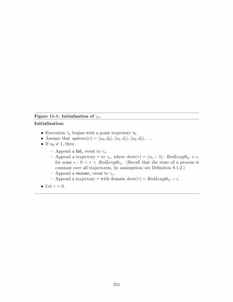
Figure 11-1: Initialization of γv.
Initialization:
• Execution γv begins with a point trajectory τ0.• Assume that updown(v) = 〈u0, d0〉, 〈u1, d1〉, 〈u2, d2〉, . . ..• If u0 6= 1, then:
– Append a failv event to γv.– Append a trajectory τ to γv, where dom(τ) = (ui − 1) · RndLengthV + ε,
for some ε : 0 < ε < RndLengthV . (Recall that the state of a process isconstant over all trajectories, by assumption; see Definition 8.1.2.)
– Append a recoverv event to γv.– Append a trajectory τ with domain dom(τ) = RndLengthV − ε.
• Let r = 0.
351

Figure 11-2: Construction of execution γv.
Loop: Repeat until 〈ur, dr〉 is not in updown(v):
• Case 1. Finite Epoch: If dr 6=∞, we consider virtual round dr:
– Construct an execution based on whether v broadcasts in round dr + 1:
∗ Subcase A. If some port 〈j, v〉 ∈ bcast-portsB broadcasts 〈vn, v, m〉,m 6= ⊥, in the vn phase of virtual round dr + 1 and also 〈vn, v, ·〉 inthe scheduled-ballot phase of virtual round dr + 1 then:
· Fix such a j; append exec(ur, dr, j)v to γv; let s = `state(γv).· Let 〈·, ·, ·, e〉 ← do-bcast(s)v.· Append execution e.failv to γv.
∗ Subcase B. Otherwise:
· Append an arbitrary execution e ∈ execs(ur, dr)v to γv. (ByLemma 11.7.8, execs(ur, dr)v 6= ∅.)· Append a failv event to the end of γv.
– Add time passage until the next epoch begins, if there is one:
∗ Subcase A. If updown(v) contains 〈ur+1, dr+1〉:· Append trajectory τ where dom(τ) = (ur+1−dr−1)·RndLengthV +
ε, for some ε : 0 < ε < RndLengthV . (Recall: the state of a processis constant over all trajectories; see Definition 8.1.2.)· Append a recoverv event to γv.· Append a trajectory τ with domain dom(τ) = RndLengthV − ε.
∗ Subcase B. Otherwise, if updown(v) does not contain any 〈ur+1, dr+1〉:· Append a trajectory τ where dom(τ) =∞ and all the variables of
virtual node v are constant.
• Case 2. Infinite Epoch: Otherwise, if dr is infinite:
– There are an infinite number of virtual rounds ≥ ur. Since α is infinite,Lemma 8.1.31 implies that there are an infinite number of basic rounds inα. Let r′ be the smallest virtual round ≥ ur such that every basic roundin virtual round r′ is ≥ rgst + 1.
– First, we construct the execution from ur to r′, and then inductively con-struct each round of the execution after that one at a time. Choose e tobe an arbitrary execution in execs(ur, r
′)v. Append e to γv. (Notice that|execs(ur, r
′)v| = 1 by Corollary 11.7.12, since r′ is a green round.)– Next, we construct each additional virtual round of execution γv induc-
tively. Given an execution through virtual round r′ where every basicround in round r′ is > rgst :
∗ Let γ′ be the (sole) execution in execs(ur, r′ + 1)v. Notice that it
extends execs(ur, r′)v, since round r′ is green for v.
∗ Append to γv all events and trajectories in γ′ not in execs(ur, r′)v.
∗ Increment round r′.
• r ← r + 1
352
11.10.1 Client Executions
We next define an execution γi, for each i ∈ IB as the restriction of α to the events andtrajectories relating to the client automaton associated with node i. More formally:
Definition 11.10.1. Let C = Remap(AV (i), i). Let γi be α|〈C.actions , C.vars〉.
(See Appendix A for the formal definition of an (A, V )-restriction of an execution.) Itfollows immediately that each γi is an execution of the remapped process Remap(AV (i), i).
We now verify that the trace of each γi is “consistent” with an execution of thevirtual infrastructure system. It is immediately clear that γi is an execution of a clientautomaton; it requires some further examination to show that the execution has theappropriate (virtual) round structure. If the client’s execution, as just defined, is acomponent execution of a virtual infrastructure system, it must have the appropriateround structure: specifically, if a client does not fail in round r, then γi contains around r bcast and a round r recv event. The first round in the execution is a specialcase: there is a recv event, but no bcast event.
Lemma 11.10.2. If node i does not fail in virtual round 1, then γi contains a singleround 1 recvi,∗ event.
For every virtual round r > 1, if node i does not fail prior to beginning round r,then γi contains a single round r bcasti,∗ event; if node i does not fail in round r,then γi contains a single round r recvi,∗ event at the end of round r.
Proof. We show that for each round r > 0, if i does not fail in r, then γi contains asingle round r recvi,∗ event. The conclusion with respect to bcast events then followsimmediately from the fact that the client is a process and γi is an execution of theclient process: a process responds with bcast events immediately and only in responseto recv events (see Definition 8.1.2).
Consider some virtual round r, and let ra be the last basic round in r. We need toshow that during virtual round r, exactly one recvi,∗ event occurs, and that it occursat the end of round ra.
We argue that the restriction on trajectories (line 721) ensures that at leastone recvi,∗ occurs immediately after the round ra recv event. Specifically, the stopswhen condition restricts the passage of time when E(multiplexer).phase i = out andE(multiplexer).failed i = false. Notice that immediately after the round ra recvi,0
event, E(multiplexer).phase i = out and E(multiplexer).failed i = false (as i does notfail prior to the end of r). The following sequence of dependencies show that a recvi,∗event must occur in order for time to pass:
• Time stops at the end of round r when E(multiplexer).phase i = out andE(multiplexer).failed i = false.
• The only event which resets the phase to in is a round ra +1 bcasti,0 event. Theprecondition of the bcasti,0 event requires E(multiplexer).clientBcast i = true.After the recvi,0 event, the client broadcast flag E(multiplexer).clientBcast i =false.
353

• The only event which sets clientBcast to true is a bcasti,∗ event.
• Since the client is a process (see Definition 8.1.2), a bcast event occurs onlyin response to a recv event. Thus the necessary bcasti,∗ event occurs only if arecvi,∗ event precedes it.
Since the process AB(i) (consisting of the composed emulator and client) is progres-sive, as per Lemma 10.3.6, we can conclude that time-passage is enabled after a finitesequence of events after the recvi,0 event, and hence at least one round r recvi,∗ eventoccurs at the end of round r.
Finally, we argue that only one recvi,∗ event occurs. Notice that a precondition ofthe recvi,∗ action in Figure 10-13 is that E(multiplexer).inVNs i = V , and an effectof the recvi,∗ action is that the set of virtual nodes E(multiplexer).inVNs i ← ∅.Moreover, a virtual node v ∈ IV is added to the set E(multiplexer).inVNs i onlyduring a vn-client-outputv event.
The virtual node emulator E(v), however, ensures that (1) vn-client-outputv eventsoccur only at the end of a virtual round, and (2) only one vn-client-outputv eventoccurs per virtual round. This follows by noticing that the vn-client-output action hasa precondition E(v).do-client-recv i = true, which is reset by the vn-client-output tofalse. Moreover, this flag is only set during the last basic round in r, i.e., during thebasic round ra recv event. Thus it is only set once per virtual round at the very endof the virtual round.
We therefore conclude that only one recvi,∗ event can occur in each virtual round,concluding our proof.
The next lemma we prove is that the clients’ interaction with the virtual broadcastservice satisfies the self delivery property. That is, we show that if some client port〈i, ∗〉 broadcasts a message m in round r, then port 〈i, ∗〉 also receives message m inround r.
Lemma 11.10.3. Let i ∈ IB be a client and r > 0 be a virtual round. If for somem ∈ msgsV , a round r bcast(m, ·)i,∗ occurs in γi and if a round r recv(M, . . .)i,∗ eventoccurs in γi, then m ∈M .
Proof. This lemma follows from the self-delivery property of the basic broadcast ser-vice. Immediately after the bcast(m, ·)i,∗ event, we can determine that E(multiplexer).outM i =m, and hence there is a bcast(〈client, m, ·〉, ·)i,0 event in the client phase of roundr. Since there is a recvi,∗ event at the end of virtual round r (by assumption), wecan conclude that i does not fail in the client phase, and hence there is a clientphase recv(M, . . .)i,∗ event. By the self-delivery property of the basic broadcast ser-vice, we know that 〈client, m, ·〉 ∈ M , and hence immediately after the recvi,∗ event,〈client, m, ·〉 ∈ inM . Thus, when the recvi,∗ occurs at the end of virtual round r, wecan conclude that m ∈M , as desired.
11.10.2 The Virtual Contention Manager Execution
We next construct an execution γvirtual of the virtual contention manager CM virtual .The construction derives entirely from the γi, i ∈ IB, and γv, v ∈ IV , executions
354

that have already been constructed: every bcast event in these executions is added toγvirtual ; for each bcast event, an immediately following cm-advice event is added.
Recall that each contention manager in the virtual infrastructure system givesadvice to every node in the system, real or virtual. However, the virtual contentionmanager here is designed to provide useful advice for the virtual nodes; thus, it alwaysadvises the clients to be passive.
For the virtual nodes, the contention manager derives its advice from the recvevents in γv, v ∈ IV . This construction thus ensures that the γvirtual execution isconsistent with the virtual node executions. As in prior constructions, we implicitlyinsert point trajectories between actions in the sequence.
The construction itself is presented in Figure 11-3. We then prove that γvirtual is anexecution of CanonicalCM (Lemma 11.10.4), that γvirtual is non-interfering (Lemma 11.10.6),and that γvirtual is eventually fair (Lemma 11.10.7).
Lemma 11.10.4. γvirtual is an execution of CanonicalCM.
Proof. Notice that γvirtual is an alternating sequence of trajectories and actions, andthat all the in γvirtual are consistent with CanonicalCM. We need only show thefollowing two facts: (1) the preconditions for transitions in CanonicalCM are satisfiedwhenever a cm-advice occurs in γvirtual ; (2) time-passage is enabled whenever τi is atrajectory with domain > 0.
First, consider some cm-advice(〈i, ∗〉, ·) event, for i ∈ IB ∪ IV . We need to showthat 〈i, ∗〉 ∈ waiting . From the construction, we can determine that γi contains animmediately preceding bcasti,∗ event, which adds 〈i, ∗〉 to the waiting set, as required.
Second, consider some trajectory τ with domain > 0. Notice that τ that wasadded in Step 3 of the construction. We need to show that in fstate(τ), waiting = ∅.That is, we need to show that for each preceding bcasti,∗ event, there is an interveningcm-advice(i, · · · ) event, for all 〈i, ∗〉 ∈ IB ∪ IV .
We can see immediately by construction that for all i ∈ IB, each bcasti,∗ eventhas an immediately following cm-advice(〈i, ∗〉, passive) event. For v ∈ IV , the sameconclusion follows: whether or not there is a recv event, some cm-advice event followseach bcastv,∗ event.
Next, we discuss the additional properties associated with the contention managerCM virtual : eventual non-interference and eventually fairness. Before proceeding, weprove a basic lemma about when a node v ∈ IV is advised by CM virtual to be active.Specifically, we show that if virtual node v is advised to be active in round r, then itis scheduled in round r; if it is advised to be passive, then it is not scheduled. Thatis, the schedule exactly determines when v is advised to be active. The claim followsimmediately from the construction of γv via the calculate-state function.
Lemma 11.10.5. For r > 0, for v ∈ IV , assume there exists a round r recv(·, ·, cm, ·)v
event in γv. If cm = active, then virtual node v is scheduled in round virtual roundr + 1; if cm = passive, then virtual node v is not scheduled in virtual round r + 1.
Proof. The main argument in the proof is that the cm parameter of the recv transitionin γv is determined by the calculate-state function which is used to construct executions
355

Figure 11-3: Constructing the Virtual Contention Manager Execution.
• Execution γvirtual begins with the point trajectory τ0.• Begin with r = 1.• Repeat:
1. For every v ∈ IV , if there is a round r bcast(m, cm)v,∗ event in γv, for anym and cm, then:
– Insert bcast(m, cm)v,∗ in γvirtual .– If there is a round r recv(·, ·, cm, ·)v,∗ event in γv, for any cm, then
insert cm-advice(〈v, ∗〉, cm)virtual in γvirtual .– Otherwise, insert a cm-advice(〈v, ∗〉, passive)virtual in γvirtual .
2. For every j ∈ IB, if there is a round r bcast(m, cm)j,∗ event in γj, for anym and cm, then:
– Insert bcast(m, cm)j,∗ in γvirtual .– Append a cm-advice(〈j, ∗〉, passive)virtual to γvirtual .
3. Append trajectory τ to γvirtual , where dom(τ) = RndLengthV .
356

of the virtual node; the calculate-state function uses the schedule to determine whethercm should be active or passive, implying the desired result. We now proceed in moredetail.
By the construction of γv, if there exists a round r recvv event in γv, then v isup in round r, which implies by the definition of an updown sequence that for somer1, r2 the following hold: (1) r ∈ [r1, r2] and (2) 〈r1, r2〉 ∈ updown(v).
Recall that γv was constructed by appending some execution in execs(r1, r′)v,
where r′ ≤ r2 and r ∈ [r1, r′], to an inductively constructed prefix. Thus, if there
is a round r recv(·, ·, cm, ·)v event in γv, then there is some execution fragment γ′ ∈execs(r1, r
′)v where a round r recv(·, ·, cm, ·)v ∈ γ′.Recall that γ′ is constructed by calling the calculate-state function. Notice that in
Figure 10-11, in each iteration of the loop, inCM is calculated in line 541cacl:schedule¿by examining the schedule: inCM = active if and only if v is scheduled in round r+1.Moreover, the cm parameter of the recv action derives from inCM (see lines 556and 566).
Thus, if there is a recv(·, ·, active, ·)v,∗ in γ′, then v is scheduled in round r + 1; ifthere is a recv(·, ·, passive, ·)v,∗ in γ′, then v is not scheduled. Together these implythe desired result.
Next, we show that γvirtual satisfies eventual non-interference and eventual fairness.The claim follows immediately from the fact that the schedule, which determineswhether v is scheduled, is complete and non-interfering.
Lemma 11.10.6. γvirtual satisfies eventual non-interference for the port set S2 =IV × {∗}.
Proof. For the purpose of eventual non-interference, we consider the stabilizationround to be 2. Consider some round r ≥ 2. We need to show that if two ports〈v, ∗〉, 〈v′, ∗〉 ∈ S2 are advised to be active by CM virtual in round r, then |loc(v) −loc(v′)| > 2R′V .
If 〈v, ∗〉 is advised by CM virtual to be active in round r, then there is an advice eventcm-advice(〈v, ∗〉, active)virtual in γvirtual , which implies, according to the constructionof γvirtual , that there must have been a round r − 1 recv(·, ·, active, ·)v,∗ event in γv.
Similarly, if 〈v′, ∗〉 is advised to be active in round r, that means that there musthave been a round r − 1 recv(·, ·, active, ·)v′,∗ event in γv′ .
By Lemma 11.10.5, we know that both ports 〈v, ∗〉 and 〈v′, ∗〉 are scheduled forround r. Since the schedule is non-interfering, we can therefore conclude that |loc(v)−loc(v′)| > 2R′B + RB = 2R′V , as desired.
Finally, we show that γvirtual is an eventually fair contention manager:
Lemma 11.10.7. γvirtual satisfies eventually fairness for S2 = IV × {∗} with delaySMAX .
Proof. For the purpose of eventual fairness, we consider the stabilization round tobe 2. Consider some round r ≥ 2. We need to show that if some port 〈v, ∗〉 ∈ S2
is not failed in rounds [r, r + SMAX], then there exists a round r′ ∈ [r, r + SMAX]
357
such that there is a round r′ − 1 recv(·, ·, active, ·)v,∗ event in γv. This implies, by theconstruction of γvirtual , that CM virtual advises 〈v, ∗〉 to be active.
First, notice that the construction of γv guarantees that if port 〈v, ∗〉 is failed ina round, then it is down in that round: if 〈ui, di〉 and 〈ui+1, di+1〉 are elements of thesequence updown(v), then v is failed in rounds [di + 1, ui+1]. (If 〈ui, di〉 is the lastelement in the sequence, then v is failed from round di + 1 onwards.)
Therefore, if 〈v, ∗〉 is not failed in rounds [r, r+SMAX], then it is up in rounds [r, r+SMAX]. We therefore conclude that in each of these rounds, there is a recv(·, ·, cm, ·)v,∗event in γv. Since the schedule is complete, there exists some r′ ∈ [r, r + SMAX] suchthat v ∈ scheduled [r′ mod SMAX], i.e., that v is scheduled. If cm = passive, thenLemma 11.10.5 would imply that v is not scheduled, resulting in a contradiction.Thus we can conclude that cm = active, concluding the proof.
11.10.3 The Client Contention Manager Execution
We now construct an execution γclient of the client contention manager CM client . Asin the case of γvirtual , the construction derives immediately from γi, i ∈ IB, and γv,v ∈ IV . As before, each broadcast event by a client or virtual node is added to γclient .Since the client contention manager is intended to provide advice to clients, in thiscase, however, γclient always advises virtual nodes to be passive, while deriving itscm-advice events from the recv events in γi, i ∈ IB.
The construction is presented in Figure 11-4. We then discuss what it meansfor a client contention manager to cm-sample the “global contention manager”, thecontention manager in the basic system; we present two lemmas relating the clientcontention manager to the global contention manager. The first, Lemma 11.10.10,shows that in fact the client contention manager is a cm-sampling of the global con-tention manager. The second, Lemma 11.10.11, shows that if the client contendsfor the client contention manager, then the multiplexer contends for the global con-tention manager. The final result, then, is showing in Lemma 11.10.12 that if theglobal contention manager satisfies certain contention fairness properties, then γclient
satisfies some related contention fairness properties.Since the construction is so similar to that of γvirtual , the same argument shows that
γclient is an execution of CanonicalCM, the canonical contention manager automaton:
Lemma 11.10.8. γclient is an execution of CanonicalCM.
Proof. Notice that γclient is an alternating sequence of trajectories and actions, andthat all the in γclient are consistent with CanonicalCM. We need only show the followingtwo facts: (1) the preconditions are satisfied whenever a cm-advice occurs in γclient ;(2) time-passage is enabled whenever τi is a trajectory with domain > 0.
First, consider some cm-advice(〈i, ∗〉, ·) event, for i ∈ IB ∪ IV . We need to showthat 〈i, ∗〉 ∈ waiting . From the construction, we can determine that γi contains animmediately preceding bcasti,∗ event, which adds 〈i, ∗〉 to the waiting set, as required.
Second, consider some trajectory τ with domain > 0. That is, consider some τthat was added in Step 3 of the construction. We need to show that in fstate(τ),
358

Figure 11-4: Constructing the Client Contention Manager Executions.
• Execution γclient begins with the point trajectory τ0.• Begin with r = 1.• Repeat:
1. For every v ∈ IV , if there is a round r bcast(m, cm)v,∗ event in γv, for anym and cm, then:
– Insert bcast(m, cm)v,∗ in γclient .– Append a cm-advice(〈v, ∗〉, passive)client in γclient .
2. For every j ∈ I, if there is a round r bcast(m, cm)j,∗ event in γj, for anym and cm, then:
– Insert bcast(m, cm)j,∗ in γclient .– If there is a round r recv(·, ·, cm, ·)j,∗ event in γj, for any cm, then
insert cm-advice(〈j, ∗〉, cm)client in γclient .– Otherwise, insert a cm-advice(〈j, ∗〉, passive)client in γclient .
3. Append trajectory τ to γclient , where dom(τ) = RndLengthV .
359

waiting = ∅. That is, we need to show that for each preceding bcasti,∗ event, there isan intervening cm-advice(〈i, ∗〉, · · · ) event, for all i ∈ IB ∪ IV .
We can see immediately by construction that for every v ∈ IV , each bcastv,∗ eventhas an immediately following cm-advice(〈v, ∗〉, passive) event. For every i ∈ IB, thesame conclusion follows: whether or not there is a recv event, some cm-advice eventfollows each bcasti,∗ event.
To this point, we have made only limited assumptions about the global contentionmanager: we have assumed that it is conservative. With no other assumptions, wecan show only that traces of the client contention manager are “sub-traces” of theglobal contention manager, in the following sense:
Definition 11.10.9. We say that γclient is a cm-sampling of some contention man-ager CM ∈ CM-namesB with respect to set S1 = IB × {∗} if the following holds forevery virtual round r > 1:
- Let ra be the first basic round in virtual round r.
- For every i ∈ IB that does not fail in virtual round r:
• There is a round r cm-advice(〈i, ∗〉, active)client in γvirtual
if and only if
• there is a round ra cm-advice(〈i, 0〉, active)CM in α.
Essentially, γclient is a cm-sampling of the global contention manager if its advicegiven at the beginning of a virtual round is equivalent to the advice given by theglobal contention manager at the beginning of that virtual round. The fact thatγclient is a cm-sampling of CM global follows from the construction of γclient , and themanner in which the multiplexer samples the global contention manager:
Lemma 11.10.10. γclient is a cm-sampling of CM global .
Proof. Consider some particular virtual round r > 1 and let ra be the first basic roundin r. Assume that i does not fail in virtual round r. We show that the constructionof γclient implies that there is a round r cm-advice(〈i, ∗〉, active)client in γvirtual if andonly if there is a round ra cm-advice(〈i, 0〉, active)global in α.
First, we consider port 〈i, 0〉. Since i does not fail in round r, it also does notfail in round ra, and ra > 1; hence there must be a round ra bcast(·, ·)i,0 event anda round ra recv(·, ·, gcm, ·)i,0 event, as per the operation of the broadcast service(see Lemmas 8.1.37 and 8.1.38). Since the regional contention managers are con-servative, by assumption, we can conclude that there are no cm-advice(〈i, 0〉, active)v
events in α. Thus, we can conclude that gcm = active if and only if there is acm-advice(〈i, 0〉, active)global event in α.
Next, we consider port 〈i, ∗〉. Since i does not fail in round r and r > 1, wecan conclude by Lemma 11.10.2 that γi contains a round r bcast(·, ·)i,∗ and a roundr recv(·, ·, ccm, ·)i,∗. From this, we conclude according to the construction that the
360
contention manager execution that γclient also contains the round r bcasti,∗ event anda round r cm-advice(〈i, ∗〉, ccm)client event.
Our goal is to show that ccm = active if and only if gcm = active. Once we haveshown this fact, the conclusion follows from the preceding argument.
Moreover, this fact follows from the operation of the multiplexer. The recvi,∗event is an output of the multiplexer, and occurs at the end of round r due tothe precondition on line 663, Figure 10-13. According to the pseudocode, cm =E(multiplexer).inCM i.
Notice, however, that E(multiplexer).inCM i is modified in only one place: duringa recvi,0 event. The recvi,0 input event occurs whenever the basic broadcast servicedelivers messages, i.e., at the end of each basic round. The only basic round ofinterest is the client round: in line 707, Figure 10-13, E(multiplexer).inCM i is mod-ified only during the client phase. (The E(multiplexer).rnd i is a correct count ofthe basic rounds by Lemma 11.2.7.) We can therefore conclude that γclient includesa round r cm-advice(〈i, ∗〉, active)client event if and only if there is a basic round ra
recvi,0(·, ·, active, ·) event in α. As per the preceding argument, this occurs if and onlyif there is a round ra cm-advice(〈i, 0〉, active)global event in α, concluding our proof.
In order to relate the two contention managers, we need one further lemma. Sofar, we have shown that the client contention manager is a cm-sampling of the globalcontention manager. We also need to show that the multiplexer contends for theglobal contention manager in a manner consistent with the way in which the clientscontend for the client contention manager. Lemma 11.10.11 shows that if a non-failedclient port 〈i, ∗〉 contends for the client contention manager in some virtual round r,then the multiplexer port 〈i, 0〉 contends for the global contention manager in thebasic rounds contained in r− 1. In fact, port 〈i, 0〉 contends for the global contentionmanager throughout the entire virtual round r − 1, with the exception only of thefirst round.
In order to use Lemma 11.10.10, we need one final lemma about the multiplexer:
Lemma 11.10.11. Assume that some port 〈i, ∗〉 contends for CM client in virtualround r, and i does not fail prior to round r. Let ra be the first basic round in virtualround r − 1. Then port 〈i, 0〉 contends for CM global in basic rounds [ra + 1, ra +RndLengthV ].
Proof. This lemma follows immediately from the operation of the multiplexer: theprecondition of the 〈bcast〉i,0 event chooses cm = global if and only if E(multiplexer).outCM i =client; the only event that modifies E(multiplexer).outCM i is the bcasti,∗ event whichoccurs only at the beginning of each virtual round (as per Lemma 11.10.2).
We can now draw some conclusions about the properties of the client contentionmanager, under certain assumptions about the global contention manager: the morepowerful the global contention manager, the more powerful the client contentionmanager; the weaker the global contention manager, the weaker the client contentionmanager. We give an example of how to use Lemma 11.10.10 to translate the powerof one global contention manager to that of the client contention manager.
361

As an example of how Lemmas 11.10.10 and 11.10.11 can be used to prove prop-erties about the client contention manager, we consider the case where CM global guar-antees eventual (a, b)-contention fairness for some integers a, b > 0. In this case,as a result of Lemma 11.10.10, we can conclude that the client contention managerguarantees eventual (a′, b′)-contention fairness:
Lemma 11.10.12. Let a, b ∈ N be integers, a, b > RndLengthV , and assume thatCM global guarantees eventual (a, b)-contention fairness with radius 2R′B + RB. Leta′ = da/RndLengthV e and b′ = bb/RndLengthV c. Then γvirtual satisfies eventual(a′, b′)-contention fairness for set S1 with radius 2R′V .
Proof. This lemma follows immediately from Lemmas 11.10.10 and 11.10.11. In thecase of γvirtual , choose the stabilization round to be the maximum of virtual round3 and the first virtual round in which every basic rounds comes after rcm + 1 forCM global from α, posited by Definition 8.1.52. Consider some virtual round r thatis no smaller than the stabilization round, and assume some port 〈j, ∗〉 contends forvirtual rounds [r, r + a′ − 1].
Let rc be the first basic round in virtual round r − 1, and recall that every basicround in round r− 1 comes after rcm . By Lemma 11.10.11 we can conclude that port〈i, 0〉 contends in basic rounds [rc + 1, rc + a′ ·RndLengthV ], that is, at least for basicrounds [rc + 1, rc + a].
By assumption, we then conclude that there exists some round rd ∈ [rc +1, rc +a]such that CM global advises 〈i, 0〉 to be active in rounds [rd, rd + b − 1], and advisesevery port within distance 2R′B + R′B to be passive in rounds [rd, rd + b− 1].
By Lemma 11.10.10, then, we can conclude that there is some round r′ ∈ [r, r+b′]where 〈i, ∗〉 is advised to be active, and every port within distance 2R′V is advised tobe passive in rounds [r, r + b′].
11.11 Integrity of the Virtual Broadcast Service
In this section, we prove a key lemma about the executions of the clients and the vir-tual nodes that we use to show that the virtual broadcast service guarantees integrity.(The execution for the virtual broadcast service is construct later in Section 11.13.)The main goal of this section is to show that if some node i ∈ IB ∪ IV receives somemessage m in virtual round r, then some other node j ∈ IB ∪ IV broadcast messagem in round r. The result is stated formally in Lemma 11.11.12.
The main structure of the proof is broken down into two lemmas: Lemma 11.11.7deals with the case where the receiving node i is a client; Lemma 11.11.11 deals withthe case where the receiving node v is a virtual node.
In both lemmas, the first step is to trace the message back to its origin, i.e., to de-termine from where it originated. Any message that originates from a client i ∈ IB inround r is relatively easy to trace, and Lemmas 11.11.1 and 11.11.2 in Section 11.11.1show that if a message 〈client, m, ·〉 ever ends up either in the multiplexer (about tobe delivered to a client), or in a ballot (about to be delivered to a virtual node), thenthere is some client j that performs a round r bcast(m, ·)j,∗ in γj, as is desired.
362

The more difficult case is tracking back messages of the form 〈vn, v′, m〉, i.e.,messages that originate at some virtual node emulator. The main difficulty is toshow that if message m is received, then a bcast(m, ·)v,∗ event occurs in γv. The twocases diverge depending on whether the receiving node is a client or a virtual node.
If the receiving node is a client (Section 11.11.4), then some multiplexer musthave delivered the message to the client via a vn-client-outputv transition, and byexamining the emulator the produced this event (i.e., the subscript v on the event),we can identify which virtual node broadcast the message. Since a vn-client-outputonly outputs a message under certain conditions, we can then argue that v must bescheduled, and that the round itself must be green for v. Moreover, the message itselfmust have been included in some ballot b broadcast by an emulator for v. At thispoint we can invoke Lemma 11.11.5 (see Section 11.11.3), a key lemma which shows,loosely, that any message of the form 〈vn, v, m〉 included in a ballot for node v in agood round is broadcast by virtual node v.
If the receiving node is a virtual node v (Section 11.11.5), somewhat more workis needed to trace back the origin of the message. First, we argue that the messagemust be in some ballot for v. Next, we identify the origin of the message: in the easycase, it is sent by v itself. Otherwise, we claim that it is only in the ballot for v if itwas previously in some ballot for v′ 6= v. Next, we show that v′ must be scheduled,and v unscheduled (Lemma 11.11.8). We then show that, in this case, round r mustbe a good round for v′ (Lemma 11.11.9) and there must be a round r ballot for v′
containing the message (Lemma 11.11.10). At this point, we conclude the proof as inthe previous case by invoking Lemma 11.11.5.
11.11.1 Tracing Messages Broadcast by Clients
Any message m received by a client or virtual node was originally introduced into thesystem by either a client or an emulator. We begin with two easy lemmas that tracemessages of the form 〈client, m, ·〉 back to the clients that originally broadcast thesemessages. Each lemma is a straightforward back-tracing of the unique sequence oftransitions that place a message of the form 〈client, m, ·〉 in the specified set.
Lemma 11.11.1. Let α′ be a prefix of α, i ∈ IB be a node, m ∈ msgsV a message(i.e., 6= ⊥). Assume that in `state(α′), 〈client, m, ·〉 ∈ E(multiplexer).inM i. Then abcast(m, ·)i,∗ occurs in α′.
Proof. We trace the message backwards along the only possible sequence of transitionsthat can arrive at 〈client, m, ·〉 ∈ E(multiplexer).inM i: from the multiplexer, back tothe recvi,0 event, back to the bcasti,0 event, back to the bcasti,∗ event at which itoriginated.
• The only transition that adds a message of the form 〈client, m, ·〉 to E(multiplexer).inM i
is recv(M, . . .)i,0 where m ∈M and E(multiplexer).rnd i indicates that the recvevent is a client phase receive event for some virtual round r.
• The only ports that broadcast in the client phase of round r are ports 〈j, 0〉, forj ∈ IB. Thus, by the integrity of the basic broadcast service (Lemma 8.1.35),
363

there must be some j ∈ IB and some bcast(〈client, m, ·〉)j,0 event in α′ precedingthe recvi,0 event.
• Since m 6= ⊥, we can conclude that E(multiplexer).outM j 6= ⊥ immediatelyprior to the bcastj,0 event. The only transition that sets outM 6= ⊥ is bcastj,∗.
• Thus, we conclude there must be a bcast(m, ·)j,∗ event in α′ that precedes thebcastj,0 event.
This second lemma assumes that a message 〈client, m, ·〉 has been places in a ballot bfor virtual round r. As before, the message is traced back to an originating broadcast.
Lemma 11.11.2. Let i ∈ IB be a node, m ∈ msgsV a message (6= ⊥). Assume thatfor some ballot b, node i broadcasts a 〈vn, v, b〉 ballot message such that 〈client, m, ·〉 ∈b.clientM . Then a bcast(m, ·)i,∗ occurs in α and precedes the broadcast of the ballot.
Proof. We trace the message backwards along the only possible sequence of transitionsthat can arrive at 〈client, m, ·〉 ∈ b.clientM : to the E(v).clientM i set, to the clientphase recvi,v transition, to the client phase bcastj,0 event, to the originating bcastj,∗event.
• Immediately prior to broadcasting ballot b, we know that 〈client, m, ·〉 ∈ E(v).clientM i.
• The only transition that adds a message of the form 〈client, m, ·〉 to E(v).clientM i
is a client phae recv(M, . . .)i,v where m ∈M .
• The only ports that broadcast in the client phase of round r are ports 〈j, 0〉, forj ∈ IB. Thus, by the integrity of the basic broadcast service (Lemma 8.1.35),there must be some j ∈ IB and some bcast(〈client, m, ·〉)j,0 event in α′ precedingthe recvi,0 event.
• Since m 6= ⊥, we can conclude that E(multiplexer).outM j 6= ⊥ immediatelyprior to the bcastj,0 event. The only transition that sets outM 6= ⊥ is bcastj,∗.
• Thus, we conclude there must be a bcast(m, ·)j,∗ event in α′ that precedes thebcastj,0 event.
11.11.2 Preliminary Lemmas Related to Ballots and Execu-tions
We now consider messages of the form 〈vn, v, ·〉, i.e., messages purported to besent by virtual nodes. The goal of this subsection and Section 11.11.3 is to proveLemma 11.11.5, which shows that if some message 〈vn, v, m〉 is included in a ballotbroadcast by an emulator for virtual node v, and if the ballot is broadcast in a goodround r, then virtual node v does in fact broadcast message m in round r in γv.
364
This lemma is an important building block for Lemma 11.11.12, which shows thatthe client and virtual node executions satisfy the integrity property.
In order to prove Lemma 11.11.5, we need two preliminary lemmas, presented inthis section. The first lemma provides the basis for the claim in Lemma 11.11.5 inthe special case where: (1) 〈r1, r2〉 delineates a finite epoch of virtual node v, (2) v isscheduled for round r2, and (3) round r2 is not red. Note that this lemma does notaddress the case where v is down in round r2; the following Lemma 11.11.4 considersthis case.
The main claim in Lemma 11.11.3 is that if some message 〈vn, v′, m〉 is in theb.vnM , where b is the round r2 ballot, and if i is the proposer that sends ballot b (inthe scheduled-ballot phase), then we can conclude that the next external action in anyextension of exec(r1, r2 − 1, i)v is the broadcast of message m. This lemma is thenused in Lemma 11.11.5 by noting that since i is the round r proposer, γv includes–and hence extends—the execution fragment exec(r1, r2, i)v, and hence message m isbroadcast in round r2 in γv, as desired.
The main idea behind the proof is to first argue that if i broadcasts a ballotcontaining message m, it must also have broadcast message m in the vn phase. Thus,i calculates the last state s in exec(r1, r2− 1, i)v in the client phase for the purpose ofchoosing the message to broadcast in the vn, and then calls do-bcast(s)v to calculatethe message, which we have already posited is m, the message included in the ballot.
Lemma 11.11.3. Assume that 〈r1, r2〉 delineates a finite epoch of virtual node v ∈ IV ,assume that v is scheduled for round r2, and that r2 > r1. Moreover, assume thatround r2 is not red for v. Let i be the proposer for round r2 and b be the ballot forround r2. We conclude the following:
• If for some m ∈ msgsV , message 〈vn, v, m〉 ∈ b.vnM , and if s is the last statein exec(r1, r2 − 1, i)v, then 〈·, m, ·, ·〉 = do-bcast(s)v.
Proof. The proof proceeds in three steps. First, we argue that i broadcasts somemessage 〈vn, v′, m′〉 in the vn phase, since by assumption it broadcasts a message in thescheduled-ballot phase. Second, we show that m′ = m. Finally, we conclude the proofby arguing that message m is calculated by examining the last state in exec(r1, r2 −1, i)v and calling the do-bast function, as described in the lemma statement. We nowproceed in more detail.
Step 1. First, notice that node i, the proposer, broadcasts a message in thescheduled-ballot phase, since v is scheduled. We therefore argue that i also broadcastsa message in the vn phase: We know that E(v).scheduled i = true, E(v).joined i = true,and E(v).roundCM =active when E(v).outgoing-msg i ← b at the end of the vn phase,in preparation for the scheduled-ballot phase. These same settings must hold at theend of the client phase when the message is chosen for the vn phase, as they arenot changed during the vn phase. In addition, since E(v).last-reset i = r1 − 1 byCorollary 11.4.5, we know that r2 6= E(v).last-reset i + 1. Thus all the conditions aremet for outgoing-msg to be set 6= ⊥ in line 240. We therefore conclude that nodei broadcasts a message in the vn phase; assume that this message is 〈vn, v, m′〉, forsome message m′ ∈ msgsV ∪ {⊥}.
365

Step 2. Second, we argue that m′ = m. That is, at the end of the client phase,E(v).outgoing-msg i = 〈vn, v, m〉.
We trace the message 〈vn, v, m′〉 forward from its broadcast in the vn phase byport 〈i, v〉 (posited in Step 1) until the formation of ballot b. Notice that 〈vn, v, m′〉 isin the set E(v).allM i immediately prior to the recv event that concludes the vn phase:this follows immediately by the self-delivery property of the basic broadcast servicewhich guarantees that node i receives every message that it sends (Lemma 8.1.36).Moreover, the message 〈vn, v, m′〉 is in E(v).nearby-msgs i after line 257 during therecv event for the vn phase of round r2.
Assume, for the sake of contradiction, that m′ 6= m. In this case, there are atleast two messages in E(v).nearby-msgs i: 〈vn, v, m〉 and 〈vn, v, m′〉. As a result ofthe condition on line 264 (Figure 10-5), the set E(v).vnM i is left unmodified, empty.This implies that 〈vn, v, m〉 /∈ E(v).vnM i, and hence contradicts our assumption that〈vn, v, m〉 ∈ b.vnM . Hence we can conclude that m = m′.
Step 3. The last step of the proof is to notice that i chooses the message next-vn-msgby first calculating temp-state = exec(r1, r2−1, i)v, and then calculating 〈next-vn-msg , ·〉 =do-bcast(temp-state)v. Node i then broadcasts 〈vn, v, next-vn-msg〉, which concludesour proof.
The second lemma in this section deals with the case where v is down in somevirtual round r. Even when a virtual node is down in a virtual round, it may broadcasta message in that round if it does not fail until after the round begins. Recall fromthe construction of γv that when a virtual node is down in a virtual round, it eitherfails at some point during that round, or begins the round already failed. In thislemma, we show that if there is a broadcast by v in a virtual round, and it is down inthat round, then it must be up in the previous virtual round. More specifically, weshow that if some non-empty ballot is sent in round r, then even though v is downin round r, v must be up in round r − 1.
Lemma 11.11.4. Let r > 0 be a virtual round, v ∈ IV a virtual node. Assume thatv is down in round r, and that there is some node i ∈ IB that broadcasts a ballot b inthe scheduled-ballot phase of round r such that 〈vn, v, m〉 ∈ b.vnM . Then, r > 1 andv is up in round r − 1.
Proof. If v is down in round r−1, then we can conclude that either (1) E(v).last-reset i =r − 1 at the beginning of the vn phase of round r, in which case b.vnM = ∅, or (2)there are no nodes that begin round r for v. Both cases imply a contradiction.
We now proceed in more detail. Assume for the sake of contradiction that one oftwo cases holds:
• r = 1, or
• r > 1 and v is down in round r − 1.
(As a technical matter, when we refer to the end of round r − 1 in the case wherer = 1, we are actually referring to the beginning of round 1, i.e., the beginning of theexecution.)
366
Since i broadcasts a ballot in the scheduled-ballot phase, we can conclude that ibegins round r: node i broadcasts a ballot only if it has E(v).joined i = true andE(v).failed i = false when the vn phase recv occurs, which is only the case when ibegins round r, as there is no opportunity to join v prior to the join phase of roundr.
If r > 1, there are two possible reasons why v is down in round r − 1 (accordingto Definition 11.3.7): either no node completes round r− 1, or virtual node v is resetin round r− 1. Thus, along with the case where r = 1, there are three possible casesto cover:
1. r = 1, or
2. r > 1 and v is down in round r − 1 due to the fact that some node resets v inround r − 1,
3. r > 1 and v is down in round r − 1 due to the fact that no node completesround r − 1.
We consider these cases as follows: (1,2) r = 1 or some node resets v in round r − 1,(3) r > 1 and no node completes round r − 1.
(1,2). Either r = 1 or r > 1 and virtual node v is reset in round r−1: If r > 1, we applyLemma 11.4.2 to conclude that at the beginning of round r, E(v).last-reset i =r − 1. If r = 1, then at the beginning of round 1, E(v).last-reset i = 0 andE(v).rnd j = 0, as each remains set to its initial value. After the client phaserecv of round 1, E(v).rnd j = 1, implying that E(v).last-reset i = r− 1. Thus, ifr = 1 or if v is reset in round r − 1, then E(v).last-reset i = r − 1.
As a result, there are no message of the form 〈vn, v, ·〉 sent in the vn phase ofround r (see line 238, Figure 10-5). Thus, by the integrity of the basic broadcastservice, there are no messages of the form 〈vn, v, ·〉 received in the vn phase ofround r. Since the ballot data structure b.vnM contains a subset of the messagesreceived in the vn phase of round r by the round r proposer, we can concludethat 〈vn, v, m〉 /∈ b.vnM , resulting in a contradiction.
(3). At the end of virtual round r − 1, for every j ∈ IB, node j does not completeround r − 1, i.e., does not begin round r. This contradicts our claim that ibegins round r.
11.11.3 Round r Ballot Implies a Round r Broadcast
In this section, we prove a key lemma which describes when a bcast event occurs inγv. Specifically, if some round r is good for virtual node v, and b.vnM 6= ∅, where bis the round r ballot, then γv includes a broadcast event for the message contained inthe ballot. Both of the main lemmas that prove the integrity of the virtual broadcastservice, Lemma 11.11.7 and Lemma 11.11.11, use this lemma as the final step to showthat some message was actually broadcast.
367

Lemma 11.11.5. Assume virtual round r > 0 is good for virtual node v ∈ IV , andthat v is scheduled for round r. Moreover, assume that some node i ∈ IB broadcastsa ballot b such that message 〈vn, v, m〉 ∈ b.vnM in the scheduled-ballot phase of roundr. Then γv contains a round r bcast(m, ·)v,∗ event.
Proof. There are two cases based on whether v is up or down in round r:
• Consider the case where v is up in round r:The proof proceeds as follows: First, we identify some r1, r2 such that someγ′ ∈ execs(r1, r2)v is included in γ. Second, we argue that r > r1, and, as aresult, conclude by Lemma 11.7.21 that γ′ extends exec(r1, r − 1, i)v, where iis the round r proposer. Third, we apply Lemma 11.11.3 to show that everyextension of exec(r1, r, i)v contains a round r bcast(m, ·)v,∗ event, and hence γv
contains such an event. We now proceed in more detail.
Step 1. Choose r1 ≤ r such that 〈r1, r〉 delineates a finite epoch of v. Chooser2 such that r ∈ 〈r1, r2〉 and 〈r1, r2〉 ∈ updown(v); we know this is possi-ble according to the construction of the updown sequence. If r2 = ∞, setr2 = max(rgst + 1, r). Recall that γv is constructed by appending some γ′ ∈execs(r1, r2)v to an already constructed prefix.
Step 2. We now show that r1 < r. Assume for the sake of contradiction thatr1 = r. Notice that for every node j ∈ IB, j does not send a message 〈vn, v, ·〉in the vn phase of round r: according to line 238 (Figure 10-5), a message isbroadcast only if E(v).rnd j 6= E(v).last-reset j + 1 and E(v).joined j = true;it is also immediately clear that a message is broadcast by port 〈j, v〉 onlyif E(v).failed j = false. In this case, however, according to Corollary 11.4.5,E(v).last-reset j = r1 − 1 at the beginning of round r, implying that port 〈j, v〉does not boadcast any messages in the vn phase of round r.
Since no message of the form 〈vn, v, ·〉 is broadcast in the vn phase of roundr, we conclude by the integrity of the basic broadcast service that no messageof this form is received in the vn phase of round r. As a result, when i formsballot b on line 275, message 〈vn, v, m〉 is not in b.vnM , contradicting our priorassumption. Thus we conclude that r1 < r.
Since r1 < r, we apply Lemma 11.7.21 to show that for every j ∈ IB thatcompletes round r2, exec(r1, r2, j)v extends exec(r1, r − 1, i)v; hence γ′ extendsexec(r1, r − 1, i)v.
Step 3. By Lemma 11.11.3, we conclude that if s is the last state in exec(r1, r−1, i)v, then 〈m, ·〉 = do-bcast(s)v.
Examine the calculation performed by calculate-state in extending exec(r1, r −1, i)v to form round r of γ′: we begin with the last state of exec(r1, r−1, i)v andperforms a do-bcast(s)v followed by a do-recv(. . .)v. Since 〈m, ·〉 = do-bcast(s)v,we can conclude that a bcast(m, ·)v,∗ occurs in γ′, and hence in γv.
• Consider the case where v is down in round r:The proof generally proceeds as follows: from the construction of γv, we identify
368

a node j′ that broadcasts a message 〈vn, v, m′〉 in the vn phase of round r and aballot b′ containing 〈vn, v, m′〉 in the scheduled-ballot phase of round r; if j′ = i,then we can conclude that m′ = m, concluding the proof; otherwise, if j′ 6= i,we can conclude that the round is not good; resulting in a contradiction.
We know by Lemma 11.11.4 that r > 1 and v is up in virtual round r − 1.Choose r1 such that 〈r1, r−1〉 delineates a (finite) epoch of v. We can concludethat 〈r1, r − 1〉 ∈ updown(v), since v is down in round r.
Recall that γv is constructed by appending some execution γ′ ∈ execs(r1, r−1)v
to a previously constructed prefix, followed by a do-bcast(s) event, where sis the last state in γ′. Moreover, recall that the execution γ′ is chosen fromexecs(r1, r − 1)v by selecting j′ ∈ IB such that γ′ = exec(r1, r − 1, j′)V and j′
broadcasts some message 〈vn, v, m′〉, m 6= ⊥, in the vn phase and some message〈vn, v, ·〉 in the scheduled-ballot phase.
Since j′ chooses message m′ to broadcast in the vn phase by calculating exec(r1, r−1, j′)v and calling do-bcast, we can conclude that bcast(m′, ·)v,∗ is the next en-abled external event in state s. Thus, the event bcast(m′, ·)v,∗ occurs in γv inround r.
It remains to show that m′ = m. Assume not, for the sake of contradiction.Recall that virtual node v is scheduled in round r. Since 〈vn, v, m〉 is in theround r ballot, some node j must have broadcast 〈vn, v, m〉 in the vn phase.This would result in two messages broadcast in the vn phase: 〈vn, v, m〉 and〈vn, v, m′〉; moreover nodes i, j, and j′ are all within distance RB/4 of loc(v)since they have E(v).joined = true; hence node i either receives two messages inthe vn phase of round r, or node i detects a collision (by Lemma 8.1.40); eithercase would result in E(v).vnM i = ∅, and hence a ballot b with b.vnM = ∅,contradicting our assumption. We thus conclude that m′ = m, and therefore abcast(m, ·)v,∗ occurs in γv in round r.
11.11.4 Clients Receiving Messages
In this section, we prove one of the two main lemmas: Lemma 11.11.7 shows thatwhen a client receives a message m, some other client or virtual node broadcast thatmessage. In the case where message m originates at a client, we use Lemma 11.11.1to trace the message back to the sender. In the case where message m originates ata virtual node, we show that the message appears in some ballot, and then invokeLemma 11.11.5 to conclude the proof.
Recall that Lemma 11.11.5 holds only when a virtual round is good. We first provea preliminary lemma which shows that a round r is good when certain conditions hold.When a node is participating in a virtual node, it is relatively straightforward to de-termine when a round is good; specifically, a round is good if E(v).round-status [r ]i =green. However, if a node is not participating in a virtual node, then this does notimmediately follow. Lemma 11.11.6, then, is of particular use in the case where some
369

node i ∈ IB delivers a message to a client, but is not participating in the virtual node.(When node i is participating in the virtual node, the lemma follows immediately.)
Lemma 11.11.6. Let v ∈ IV be a virtual node, r > 0 a virtual round, and i ∈ IB anode that does not fail prior to the end of the last agreement phase of virtual roundr. Assume the following three conditions hold:
1. Virtual node v is scheduled for virtual round r.
2. E(v).round-status [r ]i = green at the end of the last agreement phase of virtualround r.
3. E(v).ballot [r ].vnM i 6= ∅ at the end of the last agreement phase of virtual round r.
Then round r is good for v.
Proof. This lemma follows from Lemma 11.5.6: By assumption i ∈ IB is non-failedthrough the end of the last agreement phase of virtual round r. Moreover, by as-sumption, E(v).round-status [r ]i = green at the end of the last agreement phase. Itremains only to show that node i is within distance 3RB/4 of loc(v) at the beginningof the scheduled-veto-2 phase of virtual round r, and the conclusion follows.
By assumption, E(v).ballot [r ].vnM i 6= ∅ at the end of the scheduled-veto-2 phaseof virtual round r. Thus, we can conclude that E(v).ballot [r ].vnM i 6= ∅ at the end ofthe scheduled-veto-1 phase, as the ballot data structure is filled only in the vn phaseand the ballot phase.
In the scheduled-veto-1 phase recv event, however, the ballot is reset if |loc −loc(v) > RV + RB/4. Thus, we can conclude that node i is within distance 3RB/4 atthe end of the scheduled-veto-1 phase when the recv event occurs, and hence at thebeginning of the scheduled-veto-2 phase (which occurs at the same instant in time asthe scheduled-veto-1 recv event).
We can now prove the main lemma showing the integrity of the basic broadcastservice, with respect to clients receiving messages. Notice that most of the proof isrelated to the case where the client receives a message from a virtual node; tracing amessage back to a client is a straightforward application of Lemma 11.11.1.
Lemma 11.11.7. Let r > 0 be a virtual round, i ∈ IB a node, m ∈ msgsV a message,and M ⊆ msgsV a set of messages. If a round r recv(M, ·, ·, ·)i,∗ occurs in γi, then forevery m ∈ M there exists some j ∈ IB ∪ IV such that a round r bcast(m, ·)j,∗ occursin γj.
Proof. We first divide the proof into two cases, depending on whether the messageoriginated at a client or a virtual node. If a round r recv(M, ·, ·, ·)i,∗ occurs in γi,then for every m ∈ M , either 〈client, m, ·〉 ∈ E(multiplexer).inM i or 〈vn, m, ·〉 ∈E(multiplexer).inM i, as enforced by the precondition in lines 664–667, Figure 10-13.
We next dispose of the straightforward case where the message originates with aclient. Consider the case where 〈client, m, ·〉 ∈ E(multiplexer).inM i. By Lemma 11.11.1,we conclude that a bcast(m, ·)i,∗ occurs in α, and hence in γi, as required.
370
For the remainder of the proof, we consider the case where a message originatesat a virtual node. That is, consider the case where 〈vn, m, ·〉 ∈ E(multiplexer).inM i.We begin by tracing the message back to a specific vn-client-output transition whichdelivered the message to the multiplexer. We then examine the conditions underwhich the vn-client-output event occurs, leading to the conclusion that v is scheduledand that the round status is green for i at the end of the virtual round. We then showthat the round is good for v (using Lemma 11.11.6 in one case), and conclude thatfor some node k ∈ IB, port 〈k, v〉 broadcast a ballot b containing message m. Wethen apply Lemma 11.11.5 to conclude the proof. We now proceed in more detail.
There are two lines in which messages are added to the set inM : lines 651and 708 (Figure 10-13). In the first case, all the messages added have the form〈client, ·, ·〉. Hence we can assume that the message 〈vn, m, ·〉 is added as a result of avn-client-output(〈vn, m, ·〉, ·)i,v transition.
Next, we examine the preconditions under which a vn-client-output transition fromE(v)i produces message m:
• E(v).round-status [r ]i = green at the end of round r, as per line 177.
• Virtual node v is scheduled in round r, as per line 178.
• 〈vn, v, m〉 ∈ E(v).ballot [r ].vnM i, m 6= ⊥, at the end of round r, as per line 179.
There are now two cases, depending on whether i joins v in round r. In either case,we know that E(v).failed i = false through the end of round r, as a vn-client-outputtransition occurs.
• Assume i joins v in round r: We know that i does not reset v in round r, asE(v).round-status [r ]i 6= ⊥ (see line 488) at the end of round r. Thus, virtualnode v is up in round r: node i is non-failed through the end of round r, andnode i prevents the virtual node being reset in the join-veto phase.
Let basic round ra be the last agreement phase of virtual round r, and let rb
be the join-ack phase in virtual round r; thus rb > ra. Since i ∈ IB completesthe join protocol, we know that E(v).joined i = true and E(v).failed i = falseat the end of basic round rb. Therefore by Lemma 11.5.3, we conclude thatthere exists some j ∈ IB where j participates in virtual round r and at the endof basic round ra, E(v).round-status [r ]j = E(v).round-status [r ]i at the end ofround rb; also at the end of basic round ra, E(v).ballot [r ]j = E(v).ballot [r ]i atthe end of round rb.
Since E(v).round-status [r ]i = green at the end of round r2 and the virtual nodeis not reset in round r, we conclude that the round status is also green at the endof rb, and hence E(v).round-status [r ]j = green at the end of the last agreementphase of r, and hence by definition round r is green.
By the same logic, we can conclude that 〈vn, v, m〉 ∈ E(v).ballot [r ].vnM j at theend of the last agreement phase of r. Moreover, by the integrity of the basicbroadcast service (Lemma 8.1.35), we can conclude that some node k broadcastthe ballot b received by j, i.e., 〈vn, v, m〉 ∈ b.vnM .
371

• Assume i does not join v in round r: In this case, i does not join or reset virtualnode v, and hence i does not modify E(v).round-status [r ]i or E(v).ballot [r ]iafter the last agreement phase of r prior to the end of round r. Thus, atthe end of the last agreement phase of r, E(v).round-status [r ]i = green and〈vn, v, m〉 ∈ E(v).ballot [r ].vnM i, m 6= ⊥. Hence by Lemma 11.11.6, round r isgood for v.
Moreover, by the integrity of the basic broadcast service (Lemma 8.1.35), we canconclude that some node k broadcast the ballot b received by i, i.e., 〈vn, v, m〉 ∈b.vnM .
In either case, we have conclude that round r is good, virtual node v is scheduledfor round r, and that some node k broadcasts a ballot b in the scheduled-ballot phasewhere 〈vn, v, m〉 ∈ b.vnM . We then apply Lemma 11.11.5 to conclude that γv containsa round r bcast(m, ·)v,∗ event.
11.11.5 Virtual Nodes Receiving Messages
In this section, we prove the second of the two main integrity lemmas: Lemma 11.11.11shows that when a virtual node v receives a message m in some round r of γv, thensome other client or virtual node broadcast message m in round r. As before, the casewhere a virtual node receives a message from a client is relatively straightforward,and handled (for the most part) by Lemma 11.11.2. The majority of this section isexamining the case where the message originates at some virtual node v′ ∈ IV .
We begin with three preliminary lemmas. First, we show that a virtual node vcan only receive a message from another virtual node v′ in some virtual round r ifv′ is scheduled and v unscheduled. The emulator does not allow virtual nodes tosuccessfully broadcast messages when they are not scheduled: any such messagesare lost. Thus we conclude from the operation of the emulator that v′ is scheduled.Moreover, the emulator only delivers messages from nearby virtual nodes. Since vreceives a message from v′, we can conclude that the two virtual nodes are not toofar apart, and thus we conclude from the non-interference property of the schedulethat v is unscheduled.
Lemma 11.11.8. Let r > 0 be a virtual round, v ∈ IV a virtual node, m ∈ msgsV amessage, and M ⊆ msgsV a set of messages.
Assume, that for some ballot b, there is a 〈vn, v, b〉 message broadcast in eitherthe scheduled-ballot or unscheduled-ballot phase of round r, and 〈vn, v′, m〉 ∈ b.vnM ,for some v′ ∈ IV , v 6= v′. Then we conclude that virtual node v is not scheduled andvirtual node v′ is scheduled for round r.
Proof. First, assume for the sake of contradiction virtual node v′ is not scheduled.Assume node i is a node that broadcasts 〈vn, v, b〉 in a ballot round. Since by assump-tion 〈vn, v′, m〉 ∈ b.vnM , we can conclude that 〈vn, v′, m〉 ∈ E(v).vnM i when ballot bis formed in the vn phase. Thus we can conclude that 〈vn, v′, m〉 ∈ E(v).nearby-msgs i
during the vn phase recv transition. However, in this case, since v′ is not scheduled,
372

the condition on line 268 ensures that E(v).vnM i is left unmodified, that is, = ∅. Thiscontradicts our previous assumption, from which we conclude that v′ is scheduled.
Next, assume for the sake of contradiction that both virtual nodes v and v′ arescheduled. In this case, we can conclude that v and v′ are “far enough” apart, thatis, v and v′ are distance > 2R′V apart, since the schedule is non-conflicting. Let i bea node that broadcasts the ballot message 〈vn, v, b〉. As before, every message thatnode i adds to the vnM field of the ballot is received in the vn phase. Moreover,since i broadcasts a ballot, we can conclude that i is within distance RB/4 of i atthe end of the vn phase; otherwise i no longer remains joined, and hence does notsend a ballot. According to line 257, however, i includes in the set nearby-msgs onlymessages sent by virtual nodes v′ within distance RV of v, and every message thateventually ends up in the ballot b.vnM was previously in nearby-msgs . Thus, since〈vn, v′, m〉 ∈ b.vnM where ballot b is sent by port 〈i, v〉, we can conclude that v iswithin distance RV < 2R′V of v′, contradicting our conclusion that v and v′ are farenough apart due to the non-conflicting property of the schedule.
Hence, we conclude that v′ is scheduled, then v is not scheduled for virtual round r.
Next, we show that a round is good under certain conditions. Specifically, theemulator delivers messages from virtual node v′ only in rounds that are good for v′.(In rounds that are not good for v′, there may be emulators that do not agree onthe execution, and hence it is important that no externally visible behavior dependon the current state of v.) We show that if a ballot for virtual node v includes amessages from virtual node v′, then the round must be good for v′:
Lemma 11.11.9. Let v, v′ ∈ IV be two virtual nodes, r > 0 a virtual round, andassume that v is not scheduled for round r, and v′ is scheduled for round r. If〈vn, v, b〉, for some ballot b, is broadcast in the unscheduled-ballot phase of round r,and 〈vn, v′, m〉 ∈ b.vnM , then round r is good for v′.
Proof. Assume for the sake of contradiction that round r is not good for v′. The proofproceeds by identifying the node j ∈ IB that has a round status of red or orange, andnoticing that this node broadcasts a veto message in the scheduled-veto-2 phase. Asa result, the node which broadcasts ballot b either receives the veto message, detectsa collision, or is too far away from v′ for either of the two preceding options. In allcases, the ballot-broadcasting node drops message 〈vn, v′, m〉, and does not include itin the ballot, resulting in a contradiction. We now proceed in more detail.
Since round r is not good for v’, there exists some j ∈ IB that participates in v′ andhas E(v′).round-status [r ]j equal to red or orange at the end of the scheduled-veto-2phase. Notice that E(v′).round-status [r ]j is copied from E(v′).scheduled-statusj inthe scheduled-veto-2 phase, and E(v′).scheduled-statusj cannot be set to red or orangeafter the scheduled-veto-1 recv event. Thus, we can conclude that by the end of thescheduled-veto-1 recv event, E(v′).scheduled-statusj is red or orange.
Also, recall that since j participates in v′, j has E(v′).joined j set to true. There-fore node j sets outgoing-msg to 〈vn, v′, veto〉, broadcasting a veto message in the
373

scheduled-veto-2 phase. Moreover, we know that node j is within distance RB/4 ofloc(v).
Let i ∈ IB be the node that broadcasts ballot b. There are now two cases toconsider: either i is “near enough” to loc(v′) or i is “far” from loc(v′). First, con-sider the case where i is within distance 3RB/4 of loc(v′) at the beginning of thescheduled-veto-2 phase. In this case, by Lemma 8.1.40, node i either receives the vetomessage or detects a collision. In either case, E(v).scheduled-status i is set to somevalue 6= ⊥, and as a result E(v).vnM i is set to ∅ during the scheduled-veto-2 phaserecv event, as is required.
Consider the case where i is not within distance 3RB/4 of loc(v′) at the begin-ning of the scheduled-veto-2 phase. In this case, during the scheduled-veto-1 phaserecv event, E(v).vnM i is reset to ∅, and remains empty through the end of thescheduled-veto-2 phase, as required.
Thus, in either case, b.vnM = ∅, which contradicts our original assumption andconclude the proof.
The third preliminary lemma traces messages backwards from a ballot for v to aballot for v′. If a message from v′ is included in a ballot for v, then this message musthave previously been included in a ballot for v′. This lemma is key to the proof ofLemma 11.11.11 in that once the message has been traced back to a ballot for v′, wecan invoke Lemma 11.11.5 to draw the desired conclusion.
Lemma 11.11.10. Let v, v′ ∈ IV be two virtual nodes, r > 0 a virtual round,and assume that v is not scheduled for round r, and v′ is scheduled for round r.If 〈vn, v, b〉, for some ballot b, is broadcast in the unscheduled-ballot phase of round r,and 〈vn, v′, m〉 ∈ b.vnM , then there is some ballot b′ broadcast in the scheduled-ballotphase of round r where 〈vn, v′, m〉 ∈ b.vnM .
Proof. We trace back the series of necessary events for 〈vn, v′, m〉 to appear in b.vnM :When some node j broadcasts the ballot message 〈vn, v, b〉 in the unscheduled-ballot
phase, we can conclude that b.vnM = E(v).vnM j, and hence 〈vn, v′, m〉 ∈ E(v).vnM j.According to line 299 (Figure 10-6), every message 〈vn, v′, m〉 in E(v).vnM j
is contained in b′.vnM for some ballot b′ received as 〈vn, v′, b′〉 ∈ allM during thescheduled-ballot phase. The basic broadcast service integrity (Lemma 8.1.35) guaran-tees that some node broadcast ballot 〈vn, v′, b′〉, as required.
Finally, we can put the pieces together and prove the main lemma of Section 11.11:if a virtual node v receives a message in γv, then some client or virtual node musthave broadcast that message.
Lemma 11.11.11. Let r > 0 be a virtual round, v ∈ IV a virtual node, m ∈ msgsV amessage, and M ⊆ msgsV a set of messages. If a round r recv(M, ·, ·, ·)v,∗ occurs inγv, then there exists some j ∈ IB ∪ IV such that a round r bcast(m, ·)j,∗ occurs in γj.
Proof. The main structure of the proof proceeds as follows: first, we argue that forsome round r ballot b for v, either 〈client, m, ·〉 ∈ b.clientM or 〈vn, v′, m〉 ∈ b.vnM .(A third alternative is that v sent the message m itself in round r.) In the case where
374

the message originates at a client, we apply Lemma 11.11.2. In the case where themessage originates at a virtual node, we apply Lemma 11.11.10 to trace the messageback to a ballot from v′, and then Lemma 11.11.5 to conclude the proof.
First, notice that by the construction of γv, if v is down in round r, then there isno round r recv event in γv. Thus we can conclude that v is up in round r.
Since there is a round r recv(M, . . .)v,∗ in γv and v is up in round r, we knowthat there is some 〈r1, r2〉 ∈ updown(v) such that r ∈ [r1, r2]. If r2 = ∞, set r2 =max(rgst + 1, r). Thus γv is constructed using an execution γ′ ∈ execs(r1, r2)v, and asa result there is a round r recv(M, . . .)v,∗ in execution γ′. By Lemma 11.7.20, then,there is some prefix γ′′ ≤ γ′, γ′′ ∈ execs(r1, r)v where there is a round r recv(M, . . .)v,∗in γ′′. Choose j ∈ IB where j completes round r such that γ′′ = exec(r1, r, j)v, asdescribed in Lemma 11.7.20. By Lemma 11.5.3, there exists some node k ∈ IB
that participates in round r and at the end of the last agreement phase of r hasE(v).ballot [r ]k=E(v).ballot [r ]j.
Notice, then, that according to the construction of exec(r1, r, j)v and the calculate-statefunction (lines 550, 555, and 565, Figure 10-11), since there is a recv(M, . . .)v,∗ eventin γ′′, we can conclude that:
M ⊆ {m′ : 〈client, m′, ·〉 ∈ E(v).ballot [r ].clientM j} ∪{m′ : 〈vn, v′, m′〉 ∈ E(v).ballot [r ].vnM j, v 6= v′} ∪{temp-msg}
In this case, temp-msg is the message broadcast by virtual node v in round r (seeFigure 10-11). Thus, we can conclude that at the end of the last agreement phase ofr, message m is in one of the following sets:
• {m′ : 〈client, m′, ·〉 ∈ E(v).ballot [r ].clientM k}, at the end of the last agreementphase of r,
• {m′ : 〈vn, v′, m′〉 ∈ E(v).ballot [r ].vnM k, v 6= v′}, at the end of the last agree-ment phase of r,
• {temp-msg}, the round r messages broadcast in exec(r1, r, j)v.
If there is a round r bcast(m, . . .)v,∗ event in γv, then the claim is satisfied. Assume,then, that no such round r event occurs in γv. We conclude that temp-msg 6= m.
Next, notice that initially ballot [r] is a default, empty, value. It is set to be non-empty only in lines 317 and 386, when the ballot is received. We have shown, above,that ballot b = E(v).ballot [r ]k is modified from its default initial value by the endof the last agreement phase. Choose k′ ∈ IB to be the node that broadcast thatballot b for virtual node v. (We know such a node exists by the integrity of the basicbroadcast service, Lemma 8.1.35.)
Thus, either 〈client, m, ·〉 ∈ b.clientM or 〈vn, v′, m〉 ∈ b.vnM , v′ 6= v. By Lemma 11.11.2,in the former case we conclude that there is a round r bcast(m, ·)j,∗ for some j ∈ IB.
Assume, then, that 〈vn, v′, m〉 ∈ b.vnM , for some v′ ∈ IV , v′ 6= v. (Notice that, atthis point, nothing we have argued indicates that there is only one such message forone such v′; we arbitrarily choose one of them.)
375

According to Lemma 11.11.8, we can conclude that v′ is scheduled and v is un-scheduled. We will show that v′, the scheduled virtual node, broadcast message m,and v, the unscheduled virtual node, received the message.
Since k′ broadcasts a ballot for virtual node v, and v is unscheduled, we canconclude that k′ does not fail prior to the beginning of the unscheduled-ballot phase.Moreover, 〈vn, v′, m〉 ∈ E(v).ballot [r ].vnM k′ .
We now apply Lemma 11.11.9 to show that round r is good for v′: by assumption,there is some message 〈vn, v′, m〉 ∈ b.vnM . By Lemma 11.11.10, we conclude thatsome node i ∈ IB broadcasts a ballot b′ such that message 〈vn, v′, m〉 ∈ b.vnM in thescheduled-ballot phase of round r.
Finally, by Lemma 11.11.5, we conclude that γv contains a round r bcast(m, ·)v,∗event, as required.
11.11.6 Putting the Pieces Together
We now combine Lemma 11.11.7 and Lemma 11.11.11 to state the main result: if anynode i ∈ IB ∪ IV receives a message m in round r in an execution γi, then there issome j ∈ IB ∪ IV that broadcast message m in round r in execution γj.
Lemma 11.11.12. Let r > 0 be a virtual round, i ∈ IB ∪ IV a node, m ∈ msgsV amessage, and M ⊆ msgsV a set of messages. If a round r recv(M, ·, ·, ·)i,∗ occurs inγi, then there exists some j ∈ IB ∪ IV such that a round r bcast(m, ·)j,∗ occurs in γj.
Proof. The claim follows immediately from Lemma 11.11.7 and Lemma 11.11.11.
11.12 The (Virtual) Collision Detector
In this section we discuss the collision detector that is integrated into the virtualbroadcast service. (We construct the actual virtual broadcast service execution inSection 11.13; we will need the results in this section to complete the construc-tion.) Recall (from Chapter 8), that a collision detector is modelled as a set of“collision detector rules” which defines the behavior of the collision detector in eachround. The virtual collision detector encompasses the set of all rules that are completeand eventually accurate. We will show that the rule constructed is both complete(Lemma 11.12.10) and eventually accurate (Lemma 11.12.16), and hence a valid rulefor the virtual collision detector.
11.12.1 Defining the Virtual Collision Detector Rule
In this section, we define a virtual collision detector rule. We define the collisiondetector rule by extracting from α information on collisions actually detected. Thisprocess ensures that the rule is consistent with an execution of the virtual broadcastservice: whenever the virtual broadcast service delivers a collision in γj, j ∈ IB ∪ IV ,the collision detector rule specifies that a collision should be detected.
376
In Section 11.12.2, we show that the virtual collision detector rule is complete,and in Section 11.12.3 we show that the virtual collision detector rule is eventuallyaccurate. Thus we conclude that the collision detector rule is in the set of rulesspecified for the virtual infrastructure system.
Before defining the collision detector rule itself, we first define the following func-tions, which we use to extract the set of broadcast events:
• The virtual round r broadcast events for the virtual broadcast service:
BC (r) = {e : e is a round r bcast event in γi, i ∈ IB ∪ IV } .
• For all k ∈ IV , let `-pre(k) be the location of node k at the beginning of roundr, according to the broadcast service.
• The messages broadcast by round r broadcast events near node j: sentM (j, r) ={m : bcast(m, ·)k,∗ ∈ BC (r), |`-pre[j]−−`-pre[k]| ≤ RV , k ∈ IB ∪ IV }.
• The messages broadcast by round r broadcast events that may interfere withnode j: sentMinterfere(j, r) = {m : bcast(m, ·)k,∗ ∈ BC (r), |`-pre[j]−−`-pre[k]| ≤R′V , k ∈ IB ∪ IV }.
It should be noted that the set sentM (j, r) corresponds to the set sentM on line 49of Figure 8-5. Similarly, the set sentM (j, r)′ corresponds to the set sentMinterfereon line 51 of Figure 8-5. It is this correspondence that is used to show that the ruleconstructed is consistent with the execution of the virtual broadcast service. We nowdefine CD-ruleV in Figure 11-5.
11.12.2 Completeness
The goal of this section is to show that the CD-ruleV defined in Figure 11-5 is com-plete, as per Definition 8.1.12: if more messages are broadcast than are received, thena collision is detected. Since the collision detector rule is defined from informationextracted from executions γi, for i ∈ IB, and γv, for v ∈ IV , the proof involves exam-ining broadcast and receive events in these executions and showing that they implythat the collision detector rule is complete. Specifically, we need to show that if somenon-failed node i ∈ IB ∪ IV broadcasts a message m in some virtual round r, andsome non-failed node j ∈ IB ∪ IV that is nearby does not receive that message, thenj detects a collision in virtual round r. By the manner in which the collision detectorrule is constructed, this is sufficient to show completeness.
In general, the proof breaks down into four cases, depending on whether i and jare clients or virtual nodes. In each case, we assume for the sake of contradictionthat some message m is lost, yet no collision is detected. We then trace the progressof message m from the sender to the receiver, arguing at each step that either themessage successfully arrives at the next step along the path, or a collision is gener-ated, which results in the receiver detecting a collision. In this way, we produce acontradiction.
377

Figure 11-5: Constructing the Virtual Collision Detector Rule.
For every j ∈ bcast-portsV , for every r > 0:
• If a round r recv(M, cd , ·, ·)j event occurs in γj, for some M ⊆ msgs :
– Let p = |sentM (j, r)|.– Let q = |M ∩ sentM (j, r)|.– Let p′ = |sentM (j, r)′|.– Let q′ = |M ∩ sentM (j, r)′|.– Define CD-rule(〈j, ∗〉, r, p, q, p′, q′)V = cd .
• For all other values p, q, p′, q′ ∈ N not defined above:
CD-rule(i, r, p, q, p′, q′)V =
{null, if p ≤ q±, if p > q
378

We begin with a few preliminary lemmas. We then consider the case where thenode receiving the messages is a client. Next, we consider the case where the nodereceiving the messages is a virtual node. We conclude with the main proof of com-pleteness.
Preliminary Lemmas
We begin by proving two preliminary lemmas that are used in Sections 11.12.2 and 11.12.2to show that the virtual collision detector rule is complete.
The first of these two lemmas, Lemma 11.12.1 shows that if some virtual node v′
receives a message in round r and does not detect a collision, then we can concludethat round r is not red for v′; moreover, the round r ballot for v contains exactly themessages in set M , and includes no collisions. (As a point of notation, notice thatthroughout this section we tend to use the letter v to represent a virtual node thatbroadcasts a message and the letter v′ to represent a virtual node that receives somemessages.) When proving that the collision detector rule is complete, in cases wherethe receiving node is a virtual node, we can focus our attention on the round r ballot.
Lemma 11.12.1. Let v′ ∈ IB be a virtual node and r > 0 a virtual round. Assumethat a round r recv(M, cd , . . .)v′,∗ occurs where cd = null in γv′. Then:
1. Round r is not red for v′.
2. Let b be the (unique) round r ballot for v′, and let i be the round r proposer forv′. Then, in addition, we conclude:
• M = {m : 〈client, m, ·〉 ∈ b.clientM or 〈vn, ·, m〉 ∈ b.vnM }.• b.clientCD = null.
• b.vnCD = null.
Proof. The proof depends primarily on examining the calculate-state function, andnoticing that if round r is red, then the execution fragment constructed by calculate-statealways includes a round r recv(·,±, . . .)v′,∗ event, which contradicts the lemma’s hy-pothesis. Thus, the first step of the proof is to identify an execution fragment contain-ing round r that is constructed by calculate-state and used during the constructionof γv′ . The conclusions then follows from a line-by-line examination of calculate-state(Figure 10-11).
First, notice that virtual node v′ is up in round r: the construction of γv′ onlyincludes a recvv′,∗ event in round r if v′ is up. Since v′ is up in round r, then we knowthat it is included in an epoch of the updown sequence: let 〈r1, r2〉 ∈ updown(v′) bethe pair that delineates an epoch of v′ such that r ∈ [r1, r2]. If r2 = ∞, then setr2 = max(rgst + 1, r) so that 〈r1, r2〉 is a finite epoch. Since the construction of γv′
uses the epochs from the updown sequence to construct execution fragments (witha special case when an epoch is infinite), we can choose γ to be the execution inexecs(r1, r2)v′ that is used in the construction γv′ . By Lemma 11.7.20, there existssome node k′ that completes round r and γ is an extension of exec(r1, r, k
′)v′ . We
379
have now identified an execution γ that includes round r and is constructed by thecalculate-state function based on the state of node k′ at the end of round r.
Next, we examine how calculate-state constructs round r of execution γ. Specifi-cally, notice that the construction branches based on whether temp-status [r ] = greenor red (line 545, Figure 10-11). If the latter branch is chosen, i.e., if temp-status [r ] =red, then do-recv is called with the second parameter equal to ±, resulting in a roundr recv(·,±, . . .)v′,∗ in γ. However, we have assumed that cd = null, and hence canconclude that temp-status [r] = green. The array temp-status is calculated by node k′
by calling calculate-status (Figure 10-10) based on the state of k′ in the client phaseof round r. By (the contrapositive of) Lemma 11.6.8, we conclude that round r isnot red for v′.
Finally, notice that in the case where temp-status [r] = green, calculate-state con-structs the set inM (line 550, Figure 10-11) as the set:
{m : 〈client, m, ·〉 ∈ b.clientM or 〈vn, ·, m〉 ∈ ∪b.vnM } .
Since calculate-state calls do-recv with the parameter inM , we conclude that M =inM , implying the desired result.
Similarly, calculate-state calculates the collision detection parameter inCD suchthat if either b.clientCD or b.vnCD is equal to ±, then inCD = ±. However, sincecd = null in the round r recv event in γv′ , we can conclude that both b.clientCD andb.vnCD are equal to null.
The second preliminary lemma, Lemma 11.12.2, considers the case where a virtualnode v broadcasts some message m. In this case, we show that there exists some nodei that broadcasts 〈vn, v, m〉 in the vn phase of round r. That is, any message broadcastin γv in round r is also broadcast in the vn phase of round r. When proving that thevirtual collision detector rule is complete, in the cases where a virtual node broadcastsa message, we can focus our attention on the message broadcast in the vn phase.
Lemma 11.12.2. Let v ∈ IB be a virtual node, and r > 0 a virtual round. Assumethat a round r bcast(m, ·)v occurs in γv where m 6= ⊥. Assume that one of thefollowing three cases holds:
• Round r is good for v.
• Virtual node v is unscheduled for round r.
• Virtual node v is down in round r.
Then there exists some i ∈ IB that begins round r for v and remains joined and notfailed through the beginning of the scheduled-ballot phase such that:
1. There is a round r bcast(〈vn, v, m〉, ·)i,v event in the vn phase of round r.
2. If v is scheduled for round r, then there is a round r bcast(〈vn, v, b〉, ·)i,v eventin the scheduled-ballot phase of round r.
380

Proof. We begin with an overview of the proof, which divides into two cases, basedon whether v is up or down in round r. If v is down in round r, the claim followsimmediately from the construction of γv: there is a broadcast in round r of γv only ifthere is a message broadcast by some port 〈i, v〉 in the vn and scheduled-ballot phasesof round r. Since γv is constructed by the calculate-state function, which calculatesthe round r message in the same way that node i calculates the message to broadcastin the vn phase, we can conclude that port 〈i, v〉 broadcasts 〈vn, v, m〉 in the vn phase,as claimed.
If v is up in round r, the proof is slightly more complicated. We first identify anexecution fragment γ that includes round r − 1 and is used in the construction ofγv. We further restrict our attention to exec(r1, r− 1, i)v, for some i ∈ IB, and arguethat γ is an extension of exec(r1, r − 1, i)v, according to Lemma 11.7.20. Moreover,i completes round r − 1 and remains joined and not failed until the scheduled-ballotphase of round r. From this we conclude that in the last state of exec(r1, r− 1, i)v, abroadcast of message m is the next enabled external event. There are two subcases toconsider: If v is scheduled in round r, then node i is the round r proposer, and hencehas E(v).roundCM i = active. (This fact depends on the assumption that round ris good for v.) If v is not scheduled, then E(v).scheduled i = false. Thus in eithercase, port 〈i, v〉 satisfies line 239, and we are able to conclude that i broadcasts themessage 〈vn, v, m〉 in the vn phase, as claimed. It follows then that if v is scheduled,i also broadcasts a message in the scheduled-ballot phase.
We now proceed in more detail. There are two cases to consider, depending onwhether v is up or down in r:
• Assume v is down in round r. By the construction of γv, the only way inwhich a bcast event occurs in round r is the following: there exists some epoch〈r1, r − 1〉 ∈ updown(v), and there exists some node i ∈ IB such that port〈i, v〉 broadcasts a message 6= ⊥ in the vn and scheduled-ballot phases of roundr. Thus, port 〈i, v〉 broadcasts a message in the vn phase, as desired, and idoes not fail prior to the scheduled-ballot phase. It is easy to conclude that themessage is of the form 〈vn, v, ·〉.During the construction of γv, we see that m is chosen as follows: assume sis the last state of exec(r1, r − 1, i)v; v broadcasts the message specified bydo-bcast(s)v in round r of γv. When port 〈i, v〉 chooses a message to broadcastin the vn phase of round r (the calculation occurs in the client phase recv ofround r), it follows the same procedure, and hence we can conclude that thereis a bcast(〈vn, v, m〉, ·)i,v event in the vn phase of round r.
• Assume v is up in round r. Since v is up in round r, then we know that it isincluded in an epoch of the updown sequence: let 〈r1, r2〉 ∈ updown(v) be thepair that delineates an epoch of v such that r ∈ [r1, r2]. If r2 = ∞, then setr2 = max(rgst + 1, r) so that 〈r1, r2〉 is a finite epoch. Since the construction ofγv uses the epochs from the updown sequence to construct execution fragments(with a special case when an epoch is infinite), we can choose γ to be theexecution in execs(r1, r2)v that is used in the construction γv. We also know
381
that since there is a round r bcast event in γv, virtual round node v is not downin round r − 1, and hence r > r1.
Thus, by Lemma 11.7.20, there exists some node i ∈ IB that completes roundr − 1 and does not fail or set E(v).joined i = false prior to the bcasti,v event inthe scheduled-ballot phase, and γ is an extension of exec(r1, r − 1, i)v.
Since there is a round r bcast(m, ·)v,∗ event in γv and γv is an extension of γ,there is also a round r bcastv,∗ event in γ, and thus we can conclude that inthe last state s of exec(r1, r − 1, i)v, the do-bcast(s) produces message m, asthis is the procedure by which exec(r1, r− 1, i)v is extended to γ. Thus, we canconclude that in the client phase, when choosing which message to send in thevn phase, next-vn-msg is set equal to m in line 237.
If v is scheduled for round r, then, since v is up, we know by assumption, roundr is good for v. (Recall we have assumed that one of three situations held:either round r is good for v, v is not scheduled for round r, or v is down inround r.) Thus, we can conclude that i is the round r proposer for v, sinceaccording to Corollary 11.7.15, γ extends the proposer’s [r1, r − 1] execution.In this case, we conclude that E(v).roundCM i = active at the beginning of thevn phase, since i is the round r proposer.
Thus, at the end of the client phase, when the message is selected for the vnphase, we know the following: By the way in which i was chosen, we knowthat E(v).joined i = true and E(v).failed i = false. Since r > r1, we know thatE(v).last-reset i + 1 ≤ E(v).rnd i (by Corollary 11.4.5). Either v is scheduled,in which case E(v).roundCM i = active, or v is not scheduled, in which caseE(v).scheduled i = false. Thus, since m 6= ⊥, node i sets E(v).outgoing-msg i =〈vn, v, m〉 at the end of the client phase, and hence broadcast 〈vn, v, m〉 in thevn phase of round r, as desired.
Moreover, since i remains joined and not failed through the bcasti,v event inthe scheduled-ballot phase of round r, it is easy to see that if v is scheduledfor round r, then at the end of the vn phase: (1) E(v).scheduled i = true;(2) E(v).joined i = true; and (3) E(v).roundCM i = active. Thus, there is abcast(〈vn, v, b〉, ·)i,v event in the scheduled-ballot phase of round r, concludingthe proof.
Delivering Messages to a Client
Next, we consider a particular client j ∈ IB that receives some set of messages Min virtual round r and does not detect a collision. Our goal is to show that everymessage broadcast by a nearby node—be it real or virtual—is delivered to j. Webegin with Lemma 11.12.3, which shows that every messages broadcast by a nearbyclient is received by node j. This first lemma, Lemma 11.12.3, mainly focuses on themultiplexer, showing that the messages are correctly passed from the broadcastingclient to the multiplexer, broadcast by the multiplexer using the basic broadcast
382

service, received by node j’s multiplexer, and then passed from node j’s multiplexerto node j.
Lemma 11.12.3. Assume that i, j ∈ IB are two (possibly distinct) clients, and r > 0is a virtual round. Assume that a round r bcast(m, ·)i,∗, m 6= ⊥, occurs in γi and around r recv(M, null, . . .)j,∗ event occurs in γj. If j is within distance RV of i, thenm ∈M .
Proof. In this case, we trace message m forward from the sending port 〈i, ∗〉 to thereceiving port 〈j, ∗〉. The message is first passed from the client to the multiplexer ati; it is then broadcast by the multiplexer at i and received by the multiplexer at j; itis then passed from the multiplexer at j to the client at j. The only step in which themessage can be lost is when it is broadcast over the basic broadcast service from themultiplexer at i to the multiplexer at j. If the message is lost, then the multiplexerat j detects a collision, since the collision detector for the basic broadcast service iscomplete. This collision notification is then passed to the client at j, contradictingthe assumption that cd = null.
We now proceed in more detail. Since clients only broadcast on port 〈i, ∗〉 at thebeginning of a virtual round (as an immediate response to the round r − 1 recvi,∗event), we conclude that message m is broadcast in the client phase by port 〈i, ∗〉;that is, that there is a bcast(m, ·)i,∗ event in the client phase of round r in α. At thispoint, E(multiplexer).outM i ← m.
Next, the multiplexer broadcasts message m on port 〈i, 0〉. (Since the multiplexerflag E(multiplexer).clientBcast i = true, the bcasti,0 event immediately follows thebcasti,∗ event with no intervening time passage.) Thus we conclude that there is abcast(〈client, m, ·〉, ·) event in the client phase of round r (see line 694, Figure 10-13).
Since the basic broadcast service is complete and i and j are within distanceRV ≤ RB at the beginning of round r (i.e., the beginning of the client phase), eitherport 〈j, 0〉 receives this broadcast of message m, or port 〈j, 0〉 detects a collision (byLemma 8.1.40). That is, either a recv(m, . . .)j,0 event occurs in the client phase ofround r, or a recv(·,±, . . .)j,0 event occurs in the client phase of round r. The firstcase implies that m ∈ M , as desired; the second case implies a contradiction, fromwhich we conclude that this case does not occur under the assumptions of the lemma.
In the former case, where port 〈j, 0〉 receives 〈client, m, ·〉, the multiplexer at jadds message 〈client, m, ·〉 to E(multiplexer).inM j (line 708); the only transitionthat removes messages from inM is the recvj,∗ event, and thus the round r recvj,∗event delivers message m (see line 664). This implies that m ∈M .
In the latter case, where port 〈j, 0〉 detects a collision in the client phase, thecollision detection flag E(multiplexer).inCD j ← ± (line 709). No other round r eventcan set inCD 6= ±, and hence the round r recvj,∗ event delivers a collision to port〈j, ∗〉, contradicting our assumption that cd = null in the round r recvj,∗ event.
Our next goal is to prove the equivalent of Lemma 11.12.3, but in the case wherethe broadcasting node is a virtual node (instead of a client). The main part of thisargument will be showing that when virtual node v broadcasts a message in roundr, the vn-client-outputj,v delivers this message to the client (via the multiplexer). We
383
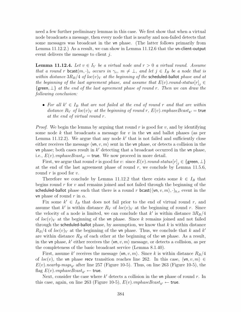
need a few further preliminary lemmas in this case. We first show that when a virtualnode broadcasts a message, then every node that is nearby and non-failed detects thatsome messages was broadcast in the vn phase. (The latter follows primarily fromLemma 11.12.2.) As a result, we can show in Lemma 11.12.6 that the vn-client-outputevent delivers the message to client j.
Lemma 11.12.4. Let v ∈ IV be a virtual node and r > 0 a virtual round. Assumethat a round r bcast(m, ·)v occurs in γv, m 6= ⊥, and let j ∈ IB be a node that iswithin distance 3RB/4 of loc(v)V at the beginning of the scheduled-ballot phase and atthe beginning of the last agreement phase, and assume that E(v).round-status [r ]j ∈{green,⊥} at the end of the last agreement phase of round r. Then we can draw thefollowing conclusion:
• For all k′ ∈ IB that are not failed at the end of round r and that are withindistance RV of loc(v)V at the beginning of round r, E(v).vnphaseBcastk′ = trueat the end of virtual round r.
Proof. We begin the lemma by arguing that round r is good for v, and by identifyingsome node k that broadcasts a message for v in the vn and ballot phases (as perLemma 11.12.2). We argue that any node k′ that is not failed and sufficiently closeeither receives the message 〈vn, v, m〉 sent in the vn phase, or detects a collision in thevn phase; both cases result in k′ detecting that a broadcast occurred in the vn phase,i.e., E(v).vnphaseBcastk′ = true. We now proceed in more detail.
First, we argue that round r is good for v: since E(v).round-status [r ]j ∈ {green,⊥}at the end of the last agreement phase of round r, we conclude by Lemma 11.5.6,round r is good for v.
Therefore we conclude by Lemma 11.12.2 that there exists some k ∈ IB thatbegins round r for v and remains joined and not failed through the beginning of thescheduled-ballot phase such that there is a round r bcast(〈vn, v, m〉, ·)k,v event in thevn phase of round r in α.
Fix some k′ ∈ IB that does not fail prior to the end of virtual round r, andassume that k′ is within distance RV of loc(v)V at the beginning of round r. Sincethe velocity of a node is limited, we can conclude that k′ is within distance 3RB/4of loc(v)V at the beginning of the vn phase. Since k remains joined and not failedthrough the scheduled-ballot phase, by assumption, we know that k is within distanceRB/4 of loc(v)V at the beginning of the vn phase. Thus, we conclude that k and k′
are within distance RB of each other at the beginning of the vn phase. As a result,in the vn phase, k′ either receives the 〈vn, v, m〉 message, or detects a collision, as perthe completeness of the basic broadcast service (Lemma 8.1.40).
First, assume k′ receives the message 〈vn, v, m〉. Since k is within distance RB/4of loc(v), the vn phase recv transition reaches line 262. In this case, 〈vn, v, m〉 ∈E(v).nearby-msgsk′ after line 257 (Figure 10-5). Thus, on line 263 (Figure 10-5), theflag E(v).vnphaseBcastk′ ← true.
Next, consider the case where k′ detects a collision in the vn phase of round r. Inthis case, again, on line 263 (Figure 10-5), E(v).vnphaseBcastk′ ← true.
384
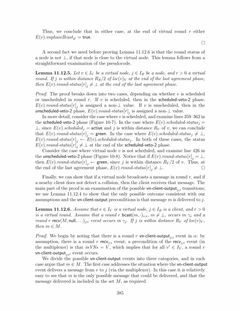
Thus, we conclude that in either case, at the end of virtual round r eitherE(v).vnphaseBcastk′ = true.
A second fact we need before proving Lemma 11.12.6 is that the round status ofa node is not ⊥, if that node is close to the virtual node. This lemma follows from astraightforward examination of the pseudocode.
Lemma 11.12.5. Let v ∈ IV be a virtual node, j ∈ IB be a node, and r > 0 a virtualround. If j is within distance RB/2 of loc(v)V at the end of the last agreement phase,then E(v).round-status [r ]j 6= ⊥ at the end of the last agreement phase.
Proof. The proof breaks down into two cases, depending on whether v is scheduledor unscheduled in round r. If v is scheduled, then in the scheduled-veto-2 phase,E(v).round-status [r ]j is assigned a non-⊥ value. If v is unscheduled, then in theunscheduled-veto-2 phase, E(v).round-status [r ]j is assigned a non-⊥ value.
In more detail, consider the case where v is scheduled, and examine lines 359–362 inthe scheduled-veto-2 phase (Figure 10-7). In the case where E(v).scheduled-statusj =⊥, since E(v).scheduled j = active and j is within distance RV of v, we can concludethat E(v).round-status [r ]j = green. In the case where E(v).scheduled-statusj 6= ⊥,E(v).round-status [r ]j ← E(v).scheduled-statusj. In both of these cases, the statusE(v).round-status [r ]j 6= ⊥ at the end of the scheduled-veto-2 phase.
Consider the case where virtual node v is not scheduled, and examine line 426 inthe unscheduled-veto-2 phase (Figure 10-8). Notice that if E(v).round-status [r ]j = ⊥,then E(v).round-status [r ]j ← green, since j is within distance RV /2 of v. Thus, atthe end of the last agreement phase, E(v).round-status [r ]j 6= ⊥.
Finally, we can show that if a virtual node broadcasts a message in round r, and ifa nearby client does not detect a collision, then the client receives that message. Themain part of the proof is an examination of the possible vn-client-outputj,v transitions;we use Lemma 11.12.4 to show that the only possible outcome consistent with ourassumptions and the vn-client-output preconditions is that message m is delivered to j.
Lemma 11.12.6. Assume that v ∈ IV is a virtual node, j ∈ IB is a client, and r > 0is a virtual round. Assume that a round r bcast(m, ·)v,∗, m 6= ⊥, occurs in γv and around r recv(M, null, . . .)j,∗ event occurs in γj. If j is within distance RV of loc(v)V ,then m ∈M .
Proof. We begin by noting that there is a round r vn-client-outputj,v event in α: byassumption, there is a round r recvj,∗ event; a precondition of the recvj,∗ event (inthe multiplexer) is that inVNs = V , which implies that for all v′ ∈ IV , a round rvn-client-outputj,v′ event occurs.
We divide the possible vn-client-output events into three categories, and in eachcase argue that m ∈M . The first case addresses the situation where the vn-client-outputevent delivers a message from v to j (via the multiplexer). In this case it is relativelyeasy to see that m is the only possible message that could be delivered, and that themessage delivered is included in the set M , as required.
385

The second case addresses the situation where the vn-client-output notifies j (viathe multiplexer) of a collision resulting from a broadcast by virtual node v. Weargue that this case cannot occur, since, by assumption, port 〈j, ∗〉 does not detect acollision in round r.
The third case addresses the situation where the vn-client-output event neitherdelivers a message to j nor notifies j of a collision. We argue that this case too isimpossible: since there is a bcastv,∗ event in γv, we can conclude (from Lemma 11.12.4)that either message m is in the round r ballot or vnphaseBcast = true. In either case,however, the preconditions of vn-client-output preclude the third case from occurring.
We now proceed to examine the three cases in more detail:
• vn-client-output(〈vn, m′, loc(v)〉, ·)j,v: In this case, some message m′ is deliveredby the emulator for virtual node v to j. We claim that in this case, as perthe operation of the multiplexer, m′ ∈ M : message 〈vn, v, m′〉 is added toE(multiplexer).inM j during the vn-client-output transition, and thus m′ is de-livered to port 〈j, ∗〉 during the (immediately) following recvj,∗ transition. (Seeline 665, Figure 10-13.) If m′ = m, this implies that m ∈M , as desired.
We argue that in fact m′ must be equal to m in this case: Since m′ is deliveredto the client port 〈j, ∗〉 for node j, we can conclude by the integrity of thevirtual broadcast service (Lemma 11.11.12) that some node k ∈ IB ∪ IV musthave sent message m′. Moreover it is clear that in this case, if one follows thepath constructed by Lemma 11.11.12 that identifies the sender of a message,virtual node v is the unique node that could have sent this message. (This isclear since all messages of the form 〈vn, v, ·〉 originate at virtual node v.) Wehave, however, assumed that virtual node v broadcast message m in round r,resulting in the conclusion that m′ = m.
• vn-client-output(⊥,±)j,v: In this case, a collision is delivered by the emulator forvirtual node v to j. We can conclude in this case that, as per the operation of themultiplexer, that a ± is delivered to port 〈j, ∗〉 during the round r recvj,∗ event,since immediately after the vn-client-output transition, E(multiplexer).inCD j =± (line 653, Figure 10-13). This contradicts our assumption that there is around r recv(M, null, ·, ·)j,∗ event in γj. Thus we conclude that this case doesnot occur.
• vn-client-output(⊥, null)j,v: In this case, no message or collision is delivered fromthe emulator for virtual node v to j. We need to show that since there is a roundr bcast(m, ·)v,∗ event in γv, this case does not occur.
We proceed to examine the preconditions for the vn-client-output transition(lines 201–207, Figure 10-4), and notice that there are only four cases thatcan result in a vn-client-output(⊥, null)j,v, as we have assumed. We examineeach of these cases in turn, and show that each implies a contradiction.
The first case is one in which the round is designated as green, the virtual nodeis scheduled, vnphaseBcast = false, and yet no message broadcast by virtualnode v appears in the ballot; this is contradicted by Lemma 11.12.4, which
386

shows that if virtual node v broadcasts a message in round r, then the messagesappears in the ballot or vnphaseBcast = true.
The second and third cases are also ones in which the round is designatedas green, but the virtual node is not scheduled. Moreover, again in thesecases, E(v).vnphaseBcast j = false. Again, Lemma 11.12.4 implies a contra-diction, indicating that since virtual node v broadcasts a message in round r,E(v).vnphaseBcast j = true.
The fourth case is one in which the round is not designated as green, but in-stead E(v).round-status [r ]j = ⊥. In this case, the contradiction is implied byLemma 11.12.5, as whenever j is near to v, we know that E(v).round-status [r ]j 6=⊥.
We now proceed in more detail to enumerate each of these cases:
– lines 187–188: E(v).round-status [r ]j = green, v is scheduled for round r,and:
6 ∃〈vn, v, ·〉 ∈ E(v).ballot [r ].vnM j .
We can also conclude that E(v).vnphaseBcast j = false, as that case hasalready been eliminated by the earlier else if clause on line 183 (Figure 10-4. There are two subcases depending on whether j joins v in round r. First,assume that j does not join v in round r. (Note that j may or may not havealready joined; we have not assumed, for example, that j is participating.)In this case, we can determine that E(v).round-status [r ]j = green at theend of the last agreement phase, as it is not modified between the end of thelast agreement phase and the end of the virtual round. By Lemma 11.12.4,Part 1, we conclude that E(v).vnphaseBcast j = true, contradicting theassumptions of this case.
If j does join v in round r, then there is some other node j′ ∈ IB thatbroadcasts the join information to j in the join-ack phase. In particular,we can conclude that E(v).round-status [r ]j′ = green, as j adopts this statefrom the join information sent by j′. By Lemma 11.12.4 we can concludethat E(v).vnphaseBcast j′ = true at the end of the last agreement phase.Since j′ sends the vnphaseBcast flag as part of the join information, wecan conclude that E(v).vnphaseBcast j = true, again contradicting the as-sumption of this case.
– lines 194–195, lines 200–201: E(v).round-status [r ]j ∈ {green,⊥}, v is notscheduled for round r, and E(v).vnphaseBcast j = false. There are twosubcases depending on whether j joins v in round r. First, assume thatj does not join v in round r. As in the previous case, we can thus de-termine that E(v).round-status [r ]j ∈ {green,⊥} at the end of the lastagreement phase, and hence we apply Lemma 11.12.4 to conclude thatE(v).vnphaseBcast j = true, contradicting the possibility that this case oc-curs.
If j does join v in round r, then there is some other node j′ ∈ IB that
387
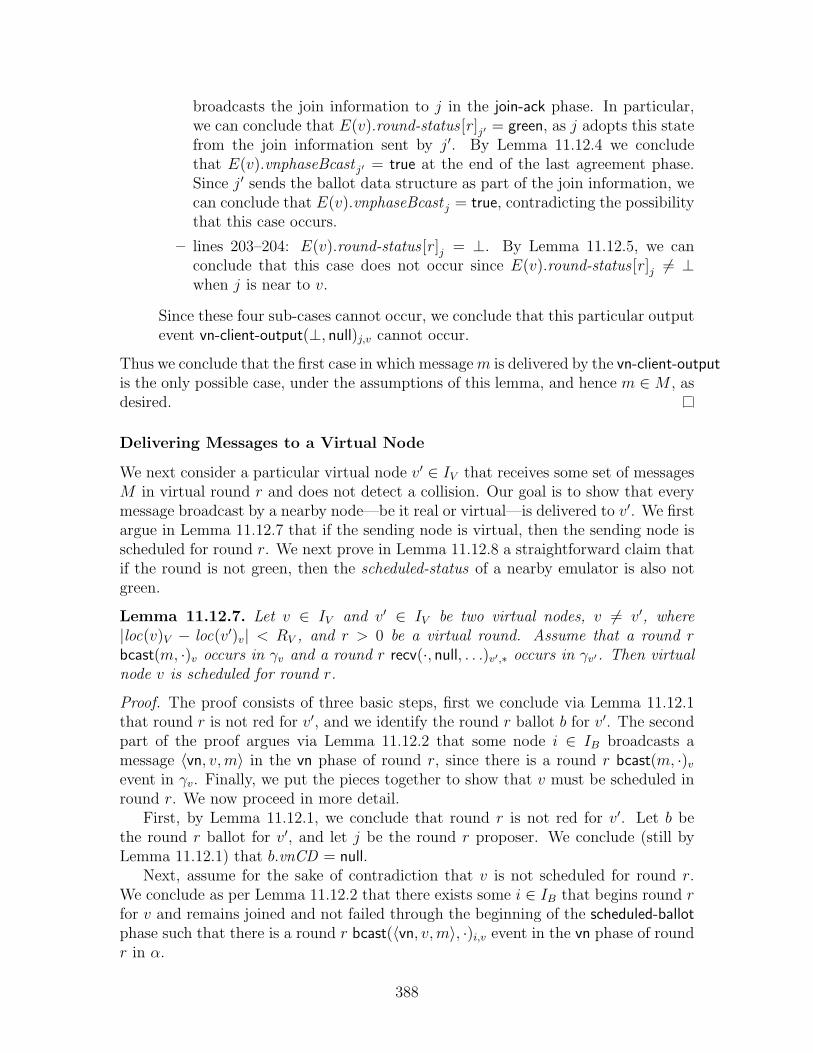
broadcasts the join information to j in the join-ack phase. In particular,we can conclude that E(v).round-status [r ]j′ = green, as j adopts this statefrom the join information sent by j′. By Lemma 11.12.4 we concludethat E(v).vnphaseBcast j′ = true at the end of the last agreement phase.Since j′ sends the ballot data structure as part of the join information, wecan conclude that E(v).vnphaseBcast j = true, contradicting the possibilitythat this case occurs.
– lines 203–204: E(v).round-status [r ]j = ⊥. By Lemma 11.12.5, we canconclude that this case does not occur since E(v).round-status [r ]j 6= ⊥when j is near to v.
Since these four sub-cases cannot occur, we conclude that this particular outputevent vn-client-output(⊥, null)j,v cannot occur.
Thus we conclude that the first case in which message m is delivered by the vn-client-outputis the only possible case, under the assumptions of this lemma, and hence m ∈M , asdesired.
Delivering Messages to a Virtual Node
We next consider a particular virtual node v′ ∈ IV that receives some set of messagesM in virtual round r and does not detect a collision. Our goal is to show that everymessage broadcast by a nearby node—be it real or virtual—is delivered to v′. We firstargue in Lemma 11.12.7 that if the sending node is virtual, then the sending node isscheduled for round r. We next prove in Lemma 11.12.8 a straightforward claim thatif the round is not green, then the scheduled-status of a nearby emulator is also notgreen.
Lemma 11.12.7. Let v ∈ IV and v′ ∈ IV be two virtual nodes, v 6= v′, where|loc(v)V − loc(v′)v| < RV , and r > 0 be a virtual round. Assume that a round rbcast(m, ·)v occurs in γv and a round r recv(·, null, . . .)v′,∗ occurs in γv′. Then virtualnode v is scheduled for round r.
Proof. The proof consists of three basic steps, first we conclude via Lemma 11.12.1that round r is not red for v′, and we identify the round r ballot b for v′. The secondpart of the proof argues via Lemma 11.12.2 that some node i ∈ IB broadcasts amessage 〈vn, v, m〉 in the vn phase of round r, since there is a round r bcast(m, ·)v
event in γv. Finally, we put the pieces together to show that v must be scheduled inround r. We now proceed in more detail.
First, by Lemma 11.12.1, we conclude that round r is not red for v′. Let b bethe round r ballot for v′, and let j be the round r proposer. We conclude (still byLemma 11.12.1) that b.vnCD = null.
Next, assume for the sake of contradiction that v is not scheduled for round r.We conclude as per Lemma 11.12.2 that there exists some i ∈ IB that begins round rfor v and remains joined and not failed through the beginning of the scheduled-ballotphase such that there is a round r bcast(〈vn, v, m〉, ·)i,v event in the vn phase of roundr in α.
388

At the beginning of the vn phase, nodes i and j are within distance RB =RB/4 + RB/4 + RB/2 of each other: node i is within distance RB/4 of loc(v)V ,since E(v).joined i = true; node j is within distance RB/4 of loc(v′)V since j broad-casts a ballot for v′ in round r, thus implying that E(v′).joined j = true; v and v′ arewithin distance RV = RB/2 of each other.
Thus, by the completeness of the basic broadcast service (Lemma 8.1.40), weconclude that node j either receives the message 〈vn, v, m〉 from i, or detects a collisionin the vn phase of round r.
In the first case, on line 270, node j sets E(v′).vnCD=±, since it discovers (online 268) that virtual node v′ is not scheduled (and v′ 6= v, by assumption). Inthe second case, on line 266, node j detects a collision, and again on line 270 setsE(v′).vnCD=±.
In either case, when the ballot for v′ is formed (on line 389), b.vnCD ← ±,contradicting our previous claim that b.vnCD = null. From this we conclude thatvirtual node v is scheduled in round r.
The following claim, Lemma 11.12.8, is quite similar to the contrapositive ofLemma 11.5.6. The main difference is that Lemma 11.5.6 examines the emulatorfor virtual node v, and conclude that all the emulators for virtual node v have acertain round status—green or yellow—when the virtual round is green for v. In thiscase, however, we are interested in emulators for some virtual node v′ 6= v. If anemulator for v′ is close to v, and if round r is not good for v, we argue that thescheduled-status for v′ is not green at the end of the scheduled-veto-2 phase.
Lemma 11.12.8. Let v, v′ ∈ IV be two virtual nodes, r > 0 a virtual round where vis scheduled for roundr, and i ∈ IB a node that is non-failed through the end of thescheduled-veto-2 phase. Moreover, assume that node i is within distance 3RB/4 ofloc(v)V at the beginning of the scheduled-veto-2 phase of virtual round r. If round r isnot good for v, then E(v′).scheduled-status i 6= green at the end of the scheduled-veto-2phase of virtual round r.
Proof. Choose some j ∈ IB that participates in virtual round r and has statusE(v).round-status [r ]j ∈ {red, orange} at the end of the scheduled-veto-2 phase of vir-tual round r. Since j has designates round r as red or orange, we argue that j broad-casts a veto message in the scheduled-veto-2 phase: Notice that since E(v).round-status [r ]jis red or orange at the end of the scheduled-veto-2 phase, E(v).scheduled-statusj mustbe red or orange at the beginning of the scheduled-veto-2 phase, as there is no later op-portunity to downgrade the round to red or orange. However, if j has scheduled-statuseither red or orange by the end of the scheduled-veto-1 recv event, then node j broad-casts a veto message in the scheduled-veto-2 phase, since node j participates in theround and has joined set to true.
Since node j and node i are within distance RB of each other, we conclude bythe completeness of the basic broadcast service (Lemma 8.1.40) that node i eitherreceives the veto message or detects a collision in the scheduled-veto-2 phase. In eithercase, node i sets E(v′).scheduled-status i 6= green, concluding the proof.
389

Finally, we can show that if a node—real or virtual—broadcasts a message inround r, and if a nearby virtual node does not detect a collision, then the virtualnode receives that message. The proof breaks down into two cases, depending onwhether the broadcasting node is real or virtual, and shows that in both cases themessage arrives successfully.
Lemma 11.12.9. Assume that v′ ∈ IV is a virtual node, j ∈ IB ∪ IV is a client ora virtual node, and r > 0 is a virtual round. Assume that a round r bcast(m, ·)j,∗,m 6= ⊥, occurs in γj and a round r recv(M, null, . . .)v′,∗ event occurs in γv′. If j iswithin distance RV of loc(v′)V , then m ∈M .
Proof. We begin by invoking Lemma 11.12.1 to conclude that round r is not red forv′. Moreover, we can determine that v is up in round r, as the construction of γv′ onlyinserts a recvv′,∗ event in round r if v′ is up. It then follows from Corollary 11.5.16that there is a unique round r proposer for v, which we label k, and a uniqure roundr ballot b for v. Also by Lemma 11.12.1, we conclude that:
• M = {m : 〈client, m, ·〉 ∈ b.clientM or 〈vn, ·, m〉 ∈ ∪b.vnM }
• b.clientCD = null.
• b.vnCD = null.
The proof now divides into two parts, depending on whether j ∈ IB or j ∈ IV ,i.e., whether j is a client or j is a virtual node.
Part 1: Assume j ∈ IB. It follows from the construction of γj that there is also abcast(m, ·)j,∗ event in α, and we can conclude that this broadcast event occurs in theclient phase of round r. By the operation of the multiplexer, port 〈j, 0〉 broadcastsmessage 〈client, m, ·〉 in the client phase of round r.
Notice that i is within distance RB of k: i is within distance RB/2 of loc(v′)V , byassumption, and k is within distance RB/4 of loc(v′)V (since a port only broadcastsa ballot if it is joined, and it only remains joined if it is near the virtual node).
We can thus conclude that at the end of the client phase, by the completeness ofthe basic broadcast service (Lemma 8.1.40), either 〈client, m, ·〉 ∈ E(v′).clientM k orE(v′).clientCDk = ±. Thus, either m ∈ b.clientM , or b.clientCD = ±. We havealready concluded that the latter case does not occur, and hence m ∈ b.clientM . Asa result, m ∈M , as per the conclusion of Lemma 11.12.1.
Part 2: Assume j ∈ IV . Assume that for some v ∈ IV where v is within distanceRB/2 of loc(v′)V , there is a round r bcast(m′, ·)v,∗ event in γv where m′ 6= ⊥. (For thesake of consistent notation, we use v here instead of j, as in the lemma statement.)
We first conclude from Lemma 11.12.7 that v is scheduled for round r. (Thisimplies that v′ is not scheduled for round r, since v and v′ are within distance RV ofeach other and the schedule guarantees non-interference.)
Next, we argue that round r is good for v. Assume for the sake of contradictionthat round r is not good for v. Then by (the contrapositive of) Lemma 11.12.8,we conclude that E(v′).scheduled-statusk 6= green at the end of the scheduled-veto-2phase, and hence E(v′).vnCDk ← ± on line 368 (Figure 10-7). Thus, when node k
390
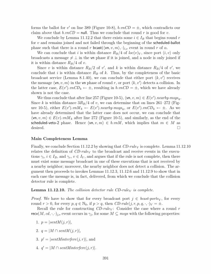
forms the ballot for v′ on line 389 (Figure 10-8), b.vnCD = ±, which contradicts ourclaim above that b.vnCD = null. Thus we conclude that round r is good for v.
We conclude by Lemma 11.12.2 that there exists some i ∈ IB that begins round rfor v and remains joined and not failed through the beginning of the scheduled-ballotphase such that there is a round r bcast(〈vn, v, m〉, ·)i,v event in round r of α.
We can conclude that i is within distance RB/4 of loc(v)V , since port 〈i, v〉 onlybroadcasts a message 6= ⊥ in the vn phase if it is joined, and a node is only joined ifit is within distance RB/4 of v.
Since v is within distance RB/2 of v′, and k is within distance RB/4 of v′, weconclude that i is within distance RB of k. Thus, by the completeness of the basicbroadcast service (Lemma 8.1.40), we can conclude that either port 〈k, v′〉 receivesthe message 〈vn, v, m〉 in the vn phase of round r, or port 〈k, v′〉 detects a collision. Inthe latter case, E(v′).vnCDk ← ±, resulting in b.vnCD = ±, which we have alreadyshown is not the case.
We thus conclude that after line 257 (Figure 10-5), 〈vn, v, m〉 ∈ E(v′).nearby-msgsk.Since k is within distance 3RB/4 of v, we can determine that on lines 261–272 (Fig-ure 10-5), either E(v′).vnM k ← E(v′).nearby-msgsk, or E(v′).vnCDk ← ±. As wehave already determined that the latter case does not occur, we can conclude that〈vn, v, m〉 ∈ E(v).vnM k after line 272 (Figure 10-5), and similarly, as the end of thescheduled-veto-2 phase. Hence 〈vn, v, m〉 ∈ b.vnM , which implies that m ∈ M asdesired.
Main Completeness Lemma
Finally, we conclude Section 11.12.2 by showing that CD-ruleV is complete. Lemma 11.12.10relates the definition of CD-ruleV to the broadcast and receive events in the execu-tions γi, i ∈ IB, and γv, v ∈ IV , and argues that if the rule is not complete, then theremust exist some message broadcast in one of these executions that is not received bya nearby neighbor; moreover, the nearby neighbor does not detect a collision. The ar-gument then proceeds to invokes Lemmas 11.12.3, 11.12.6 and 11.12.9 to show that ineach case the message is, in fact, delivered, from which we conclude that the collisiondetector rule is complete.
Lemma 11.12.10. The collision detector rule CD-ruleV is complete.
Proof. We have to show that for every broadcast port j ∈ bcast-portsV , for everyround r > 0, for every p, q ∈ N0, if p > q, then CD-rule(j, r, p, q, ·, ·)V = ±.
Recall the rule for constructing CD-ruleV : Consider the case where a round rrecv(M, cd , ·, ·)j,∗ event occurs in γj, for some M ⊆ msgs with the following properties:
1. p = |sentM (j, r)|,
2. q = |M ∩ sentM (j, r)|,
3. p′ = |sentMinterfere(j, r)|, and
4. q′ = |M ∩ sentMinterfere(j, r)|.
391

Then the construction specifies that CD-rule(r, p, q, p′, q′)V = cd . If p > q, we mustshow that cd = ±.
In all other cases, i.e., for all j ∈ IB, p, p′, q, q′ ∈ N0 where the round r recv eventdoes not satisfy Properties 1–4, the desired conclusion follows immediately from thedefinition of CD-ruleV . For the rest of this proof, fix j ∈ IB, r ∈ N, p, p′, q, q′ ∈ N0,where p > q, such that the round r recv(M, cd , . . .)j,∗ in γj satisfies Properties 1–4.Assume for the sake of contradiction that cd = null.
We begin by choosing a message m 6= ⊥ that will be of interest: since p > q,we can fix some m ∈ sentM (j, r) such that m /∈ M ∩ sentM (j, r), i.e., m /∈ M .Every message in sentM (j, r) originates (by definition) with either a bcasti,∗ event,for i ∈ IB, or a bcastv,∗ event, for v ∈ IV , where the sending node is within distanceRV of node j at the beginning of round r. Thus we can identify some node i ∈ IB orv ∈ IV that broadcasts message m.
We proceed to consider the four cases separately, depending on whether j is aclient or a virtual node, and depending on whether the sender of m is a client or avirtual node: (1) i ∈ IB and j ∈ IB are both clients; (2) v ∈ IV is a virtual node;j ∈ IB is a client; (3) i ∈ IB is a client, j ∈ IV is a virtual node; (4) v ∈ IB is a virtualnode, j ∈ IV is a virtual node.
1. There is a bcast(m, ·)i,∗ event in round r in γi for some i ∈ IB, and a recv(M, null, . . .)j,∗in round r for some j ∈ IB: We invoke Lemma 11.12.3 to conclude that since jis within distance RV of i, m ∈ M . This, however, contradicts our assumptionthat m /∈M .
2. There is a bcast(m, ·)v,∗ event in γv for some v ∈ IV , and a recv(M, null, . . .)j,∗ inround r for j ∈ IB: We invoke Lemma 11.12.6 to conclude that since j is withindistance RV of loc(v)V , m ∈ M . This, however, contradicts our assumptionthat m /∈M .
3. There is a bcast(m, ·)i,∗ event in round r in γi for some i ∈ IB, and a recv(M, null, . . .)v′,∗in round r for some v′ ∈ IV : We invoke Lemma 11.12.9 to conclude that sincej is within distance RV of loc(v′)V , m ∈ M . This, however, contradicts ourchoice of m above.
4. There is a bcast(m, ·)v,∗ event in round r in γv for some v ∈ IV , and a recv(M, null, . . .)v′,∗in round r for some v′ ∈ IV : We invoke Lemma 11.12.9 to conclude that sinceloc(v)V is within distance RV of loc(v′)V , m ∈ M . This, however, contradictsour choice of m above.
11.12.3 Eventual Accuracy
The goal of this section is to show that the CD-ruleV defined in Section 11.12 iseventually accurate (as per Definition 8.1.14). As in Section 11.12.2, the proof involvesexamining broadcast and receive events in executions γi, for i ∈ IB, and γV , for v ∈ IV ,and showing that they imply that the collision detector rule is eventually accurate.
392

Specifically, we need to show that from some virtual round onwards, if some non-failed node i ∈ IB ∪IV detects a collision in a virtual round r, then some nearby nodej ∈ IB ∪ IV broadcasts a message m in round r that is not received by i. By themanner in which the collision detector rule is constructed, this is sufficient to showeventual accuracy. In fact, we show that the collision detector rule stabilizes in roundrgst + 1.
Preliminary Lemmas
We begin with some preliminary lemmas. The key difficulty in proving eventualaccuracy is showing that when ± is recorded by the ballot [r] data structure in someround r ∈ IB (for a round r large enough), then in fact some message was broadcastby a nearby node and not received. The ballot data structure records collisions intwo subfields: the clientCD field, for collisions that originate from messages sent inthe client phase, and the vnCD field, for collisions that originate from messages thatoriginate in the vn phase. In each case, we trace the collision back until we findthe message that was lost. Lemma 11.12.11 considers the case where a message isbroadcast in the client phase; Lemma 11.12.12 considers the case where a message isbroadcast in the vn phase.
Our first claim, Lemma 11.12.11 shows that if a message 〈client, m, ·〉 is broadcastin the client phase of round r by some i ∈ IB, then message m is broadcast in roundr of γi. The lemma follows almost immediately from the construction of γi and theoperation of the multiplexer:
Lemma 11.12.11. Let i ∈ IB be a node, and assume that α contains a bcast(〈client, m, ·〉, ·)i,0
event, m 6= ⊥, in the client phase of round r. Then, there is a round r bcast(m, ·)v
event in γi.
Proof. The multiplexer port 〈i, 0〉 broadcasts a message 〈client, m, ·〉 in the client phaseof round r only if E(multiplexer).outM i = m. However, E(multiplexer).outM i = m,m 6= ⊥, only if there is a preceding bcast(m, ·)i,∗ event. It remains only to arguethat this preceding bcasti,∗ event occurs in the client phase of round r. By the useof the clientBcast flag and the stops when condition limiting the trajectories of themultiplexer, we know that the bcasti,0 event immediately follows the bcast i,∗ eventwith no intervening time passage: the bcast i,0 transition is the only one which resetsthe clientBcast flag. Thus we conclude that the preceding bcasti,∗ event occurs in theclient phase of round r. Since γi contains every client phase bcasti,∗ event, we thusconclude that there is a round r bcast(m, ·)i,∗ event in γi.
Our next claim, Lemma 11.12.12, proves a similar claim as Lemma 11.12.11,except with respect to messages broadcast in the vn phase, rather than the clientphase. Specifically, we show that if some message 〈vn, v, m〉 is broadcast in the vnphase in a round r ≥ rgst + 1, then for some virtual node v ∈ IV , message m isbroadcast in round r in execution γv. That is, every message broadcast in the vnphase is also broadcast in the execution of the virtual system. (Notice that now weare considering round rgst + 1, rather than round rgst ; the emulator takes one roundto stabilize.)
393

This lemma is almost the converse of Lemma 11.12.2, which states that if a mes-sages m is broadcast in round r of γv, then message 〈vn, v, m〉 is broadcast in thevn phase of round r. The main difference is that Lemma 11.12.2 holds from the be-ginning of the execution, while Lemma 11.12.12 holds only for rounds r ≥ rgst + 1.(There are also some differences in the precise conditions under which the respectivelemmas hold; for example, Lemma 11.12.2 assumes that if v is scheduled, then roundr is good for v.) In many ways, Lemma 11.12.12 is the key lemma necessary to provethe eventual accuracy of the collision detector rule.
Lemma 11.12.12. Let r ≥ rgst + 1 be a virtual round, i ∈ IB be a node, and v ∈ IV
be a virtual node. Assume that α contains a bcast(〈vn, v, m〉, ·)i,v event, m 6= ⊥, inthe vn phase of round r. Then, there is a round r bcast(m, ·)v,∗ event in γv.
Proof. The proof proceeds in three steps. First, we identify an epoch 〈r1, r2〉, wherer1 < r ≤ r2 + 1, such that the (sole) execution γ′ ∈ execs(r1, r2)v is used in theconstruction of γv. (By Lemma 11.8.12 we know that round r2 is green, and hencewe can conclude by Corollary 11.7.12 that there is only one execution in the set.)Second, we identify an execution γ < γ′ which includes round r − 1, but not roundr. Since there is also only one execution in the set execs(r1, r − 1)v (for the samereasons as there is only one execution in execs(r1, r2)v), and since there is a message〈vn, v, m〉 broadcast in the vn phase of round r, we can conclude that in the last stateof γ, virtual node v is enabled to broadcast message m. Finally, we conclude theproof by arguing that this broadcast event occurs in γ′, and hence also in γv.
First, by Lemma 11.8.12, we conclude that round r is green, and by Corol-lary 11.5.7, that round r is good. Choose r1, r2 such that 〈r1, r2〉 ∈ updown(v)delineates an epoch of v and r ∈ [r1, r2 + 1]. This is possible since v is up in roundr−1—otherwise no broadcast occurs in round r in the vn phase—and since r ≥ rgst+1,we can conclude that round r−1 is good, which implies that r−1 is included in someepoch of the updown sequence, since the updown sequence contains maximal epochs.If r2 =∞, then set r2 = r so that 〈r1, r2〉 is a finite epoch of v.
The next fact to notice is that r > r1: if r = r1, then E(v).last-reset i = r1 − 1at the beginning of the client phase of round r, according to Corollary 11.4.5; thus,E(v).rnd i = E(v).last-reset i + 1, and E(v).outgoing-msg i is unmodified in line 240,resuling in the broadcast of ⊥ in the vn phase, contradicting our hypothesis that somemessage 〈vn, v, m〉 is broadcast in the vn phase. Thus we conclude that r > r1.
Next, note that by Lemma 11.8.12, both rounds r−1 and r2 are both green, sincev is up in both of these rounds. By Corollary 11.7.12, |execs(r1, r − 1)v| = 1 and|execs(r1, r2)v| = 1. Fix γ ∈ execs(r1, r − 1)v, and γ′ ∈ execs(r1, r2)v. We invokeLemma 11.7.20 to conclude that γ′ is an extension of γ: the lemma states that γ′ inan extension of some execution in execs(r1, r − 1)v; γ is the only one.
Next, notice that according to the construction of γv, γ′ is included in γv. In thecase where 〈r1, r2〉 ∈ updown(v) (i.e., the case where the epoch containing r is finite),this is immediate by construction. In the case where 〈r1, r2〉 /∈ updown(v), this followsfrom the manner in which γv is constructed by successive extension.
Finally, we argue that the γ′ extension of γ contains a round r bcast(m, ·)v event.Since node i broadcasts a message 〈vn, v, m〉 in the vn phase of round r, we conclude
394

that E(v).outgoing-msg i = 〈vn, v, m〉 at the end of the client phase of round r. Themessage m is constructed in lines 235–237 by calculating the last state s of γ =exec(r1, r − 1, i)v, and then calling the function do-bcast(s).
Recall that γ′ extends γ be first calling do-bcast on s, the last state in γ (seeFigure 10-11). Thus we conclude that γ′ contains a round r bcast(m, ·)v event, fromwhich we conclude that γv contains a round r bcast(m, ·)v,∗ event, as desired.
In the previous two lemmas, we argued that a broadcast in the client or vn phasesindicates a similar broadcast in γi, i ∈ IB, or γv, v ∈ IV (respectively). The nextstep in tracing the cause of the collision is to show that a collision in the clientCDor vnCD fields of the ballot indicate that some message was in fact broadcast in theclient or vn phases, and that this message was lost. When combined with the twoprevious lemmas, this indicates that there was a message broadcast in γi, i ∈ IB orin γv, v ∈ IV , that was lost, hence justifying the collision.
More specifically, in Lemma 11.12.14, we assume that there is a ballot b broad-cast for some virtual node v ∈ IV in one of the two ballot phases of round r, andthat this ballot indicates a collision in the client phase, i.e., b.clientCD = ±. Weconclude that in this case, there is some message m that was broadcast by j ∈ IB
in round r of execution γj. Moreover, this message m is not included in the ballot,i.e., 〈client, m, ·〉 /∈ b.clientM . Thus, messages m was broadcast in round r and notreceived. Finally, we note that j is within the interference range of node v, and hencev’s collision detector is behaving accurately when it detects a collision in round r.
Lemma 11.12.13. Let v ∈ IV be a virtual node, and r ≥ rgst + 1 a virtual round inwhich some node i ∈ IB broadcasts a ballot b in a ballot phase, either the scheduled-ballotphase of the unscheduled-ballot phase.
Assume that ballot E(v).b.clientCD i = ± immediately after either (1) line 275 inthe vn phase of round r, or (2) line 389 in the unscheduled-ballot phase of round r,i.e., immediately after the ballot is created.
Then there exists some m ∈ msgsV and some j ∈ IB where j is within distanceR′V of v at the beginning of round r, such that a round r bcast(m, ·)j,∗ event occursin γj and 〈client, m, ·〉 /∈ E(v).b.clientM i immediately after the ballot b is set.
Proof. The proof consists of three steps. First, we identify a recv(·, cd , . . .)i,v eventwhere cd = ± in the client phase of round r; this is the event which results in thecollision indication in the ballot. Second, we conclude that as a result if the eventualaccuracy of the basic broadcast service, there is some bcastj,0 event that broadcasts amessage 〈client, m, ·〉 in the client phase that is lost. Finally, we apply Lemma 11.12.11to conclude that message m is broadcast in round r of γj, completing the proof.
First, notice that ballot b is formed from the E(v).clientM i variable (as well asclientCD , vnM , and vnCD). Moreover, prior to the ballot being formed, the clientCDvariable is modified only in the client phase of virtual round r, specifically, on line 228(Figure 10-5), E(v).clientCD i ← cd . Thus we conclude in this case that cd = ± inthe client phase recv(·, cd , . . .)i,v for round r.
Second, by the eventual accuracy of the basic broadcast service (Lemma 8.1.42),we can conclude that if cd = ±, then there is some message sent in the client phase by
395

a nearby port that was not delivered. That is, there exists some port p ∈ bcast-portsB
such that p is within distance R′B of i at the beginning of the client phase (and hence,the beginning of virtual round r) and a round r bcast(m′, ·)p event occurs in α.Moreover, since message m′ never arrives at port 〈i, v〉, it is straightforward to seethat message m′ is never added to E(v).clientM i, and hence m′ /∈ b.clientM .
Notice, however, that for all j ∈ IB, for all v ∈ IV , port 〈j, v〉 does not broadcastin the client phase of round r. Thus we conclude that port p is a multiplexer port,i.e., for some j ∈ IB, port p = 〈j, 0〉; fix this node j ∈ IB. Thus j is within distanceR′B of i. Since i is within distance RB/4 of loc(v)V (as it must be joined to broadcasta ballot, we conclude that j is within distance R′V ≥ R′B + RB/4 of loc(v)V .
We can also conclude that m′ = 〈client, m, ·〉, for some m ∈ msgsV , as per line 694(Figure 10-13), since the multiplexer only broadcasts messages of this form. (We havealready concluded that m′ 6= ⊥, as the eventual accuracy property indicates that anon-⊥ message is broadcast.)
Finally, by Lemma 11.12.11, we conclude that there is a round r bcast(m, ·)j,∗event in γj. Since 〈client, m, ·〉 /∈ b.clientM , this concludes our proof.
In Lemma 11.12.14 we prove the equivalent result for collision detected in thevn phase. More specifically, we assume that there is a ballot b broadcast for somevirtual node v ∈ IV in one of the two ballot phases of round r, and that this ballotindicates a collision in the vn phase, i.e., b.vnCD = ±. We conclude that in thiscase, there is some message m that was broadcast by v′ ∈ IV in round r of executionγv′ . Moreover, this message m is not included in the ballot, i.e., 〈vn, v′, m〉 /∈ b.vnCD .Thus, messages m was broadcast in round r and not received. Finally, we note that v′
is within the interference range of node v, and hence v’s collision detector is behavingaccurately when it detects a collision in round r.
Lemma 11.12.14. Let v ∈ IV be a virtual node, and r ≥ rgst + 1 a virtual round inwhich some node i ∈ IB broadcasts a ballot b in a ballot phase, either the scheduled-ballotphase of the unscheduled-ballot phase.
Assume that ballot E(v).b.vnCD i = ± immediately after either (1) line 275 in thevn phase of round r, or (2) line 389 in the unscheduled-ballot phase of round r, i.e.,immediately after the ballot is created.
Then for some message m ∈ msgsV , for some v′ ∈ IV , v′ 6= v, where v′ is withindistance R′V of v (at the beginning of round r1), we conclude that there is a round rbcast(m, ·)v′,∗ event in γv′ and that 〈vn, v′, m〉 /∈ E(v).b.vnM i immediately after theballot b is set.
Proof. The ballot is created in either line 275 or line 389 from E(v).vnM i andE(v).vnCD i (along with E(v).clientM i , E(v).clientCD i , and E(v).prev-rnd i ).We trace back the point at which E(v).vnCD i was set to ±, and identify a messagethat was lost.
At some point prior to the ballot being formed we know that E(v).vnCD i is set to±, by assumption. The collision flag E(v).vnCD i are first initialized during round r in
1Recall that virtual nodes are not mobile.
396

the vn phase recv transition. The collision flag E(v).vnCD i is then potentially modi-fied, i.e., set to ±, once in the vn phase—line 270—and once in the scheduled-veto-2phase—line 368. We examine the possible points at which this could have occurred,and show that it implies that some message m was broadcast in the vn phase thatis not included in vnM . We then invoke Lemma 11.12.12 to show that m was alsobroadcast in γv′ , for some v′ ∈ IV that is within the interference range of v, concludingthe proof.
1. The first case where E(v).vnCD i ← ± is on line 270 (Figure 10-5) under threeconditions: (1) port 〈i, v〉 received more than one message from a nearby virtualnode, (2) port 〈i, v〉 received a message from an unscheduled virtual node, or(3) port 〈i, v〉 detected a collision. In each of these cases, the set of messagesE(v).vnM i remains empty (as initialized on line 258), and hence when the ballotb is formed, b.vnM = ∅, and no messages are delivered to v from a node v′ 6= vin round r. It remains to show that some message m was broadcast in γv′ forsome v′ 6= v near to v. We consider separately the three sub-cases that triggerthe execution of line 270:
• line 264: Immediately prior to line 270, |E(v).nearby-msgs i| > 1. No-tice, however, that there is at most one message of the form 〈vn, v, ·〉 inE(v).nearby-msgs i since round r ≥ rgst , and hence at most one joined, non-failed node has E(v).roundCM =active and broadcasts a message in the vnphase. Thus, there must be some message 〈vn, v′, m〉 in E(v).nearby-msgs i
where v′ 6= v. We can determine that the message was sent by some port〈k, v′〉 in the vn phase, for some k ∈ IB (by the integrity of the basic broad-cast service). We then invoke Lemma 11.12.12 to conclude that there isa bcast(m, ·)v′,∗ event in γv′ . As argued above, 〈vn, v′, m〉 /∈ b.vnM , asb.vnM = ∅.• line 266: In this case, cd = ±. By the eventual accuracy of the basic
broadcast service (Lemma 8.1.42), since cd = ± in the recv(·, c, . . .)i,v
transition in the vn phase of round r, there is some message m′ that wassent by a port 〈j, v′〉, j ∈ IB, v′ ∈ IV , in the vn phase, where j is withindistance R′B of i, and message m′ is not received by i in the vn phase ofround r. Since j is within distance R′B of i, and i and j are within distanceRB/4 of v and v′ (respectively), we can conclude that v is within distanceR′B + RB/2 = R′V of v′.
All the messages sent in the vn phase are of the form 〈vn, v′, ·〉; therefore,we conclude that for some m ∈ msgsV there is a bcast(〈vn, v′, m〉, ·)j,v′
event in the vn phase of round r.
By Lemma 11.12.12, we conclude that there is a bcast(m, ·)v′,∗ event in γv′ .Since 〈vn, v′, m〉 is not received by i in the vn phase, message 〈vn, v′, m〉 /∈E(v).nearby-msgs i, and hence is not included in the ballot b.vnM .
It remains only to show that v 6= v′. If v = v′, then we argue thati = j, which implies by the self-delivery property of the basic broad-cast service that j receives message m′ = 〈vn, v′, m〉 in the vn phase
397

of round r, contradicting our choice of message m′. Thus it suffices toshow that if v = v′, then i = j. Recall that node i was selected be-cause it broadcasts ballot b in a ballot phase. Thus we conclude thatE(v′).roundCM i = E(v).roundCM i = active at the end of the client phase(since roundCM is modified only in the client phase of round r). More-over, since port 〈j, v〉 broadcasts a message in the vn phase, we can con-clude that E(v).roundCM j = active at the end of the client phase. How-ever, Lemma 11.8.3 shows that there is at most one node i ∈ IB that hasE(v).roundCM i = active at the end of the client phase of round r, and thusi = j, resulting in the desired contradiction. We conclude that v 6= v′.
• line 268: In this case, there exists a message 〈vn, v′, m〉 from some unsched-uled virtual node v′ in nearby-msgs , where v′ 6= v. By the definition ofthe set nearby-msgs , we know that v′ is within distance RV of v. We candetermine that the message was sent by some port 〈k, v′〉 in the vn phase,for some k ∈ IB (by the integrity of the basic broadcast service). We theninvoke Lemma 11.12.12 to conclude that there is a bcast(m, ·)v′,∗ event inγv′ . As argued above, 〈vn, v′, m〉 /∈ b.vnM , as b.vnM = ∅.
2. The second case where E(v).vnCD i ← ± is on line 368 (Figure 10-7) in thescheduled-veto-2 phase. In this case, E(v).scheduled-status i 6= ⊥ and E(v).scheduled i =false (due to the if/else condition lines 358 and 366, Figure 10-7). Additionally,we can determine that i does not fail prior to the end of the scheduled-veto-2phase (or it would not reach the line in question). However, according toLemma 11.8.8, E(v).scheduled-status i = ⊥, implying that this case does notoccur.
Thus we conclude that there exists some m ∈ msgsV , m 6= ⊥, and some v′ ∈ IV ,v′ 6= v, where v′ is within distance R′V of v such that a round r bcast(m, ·)v′,∗ eventoccurs in γv′ and 〈vn, v′, m〉 /∈ E(v).b.vnM i immediately after the ballot b is set.
The previous four lemmas address the case where a collision is detected in a ballotfor some virtual node. Thus, these lemmas are used to show that if a virtual nodev ∈ IV detects a collision in round r of γv, then some message is lost. The finalpreliminary lemma is related to the case where a client j ∈ IB detects a collision inround r of γi. We show that if a vn-client-output delivers the collision notification to i(via the multiplexer), then some message broadcast by a virtual node v ∈ IV is lost.
Lemma 11.12.15. Let v ∈ IV be a virtual node, j ∈ IB a client, and r ≥ rgst + 1 avirtual round. Assume a vn-client-output(m,±)j,v occurs at the end of virtual round rin α. Then m = ⊥ and for some v′ ∈ IV , where j is within distance R′V of loc(v′)V ,there exists a round r bcast(m′, ·)v′,∗ event in γv′, where m 6= ⊥.
Proof. The proof proceeds as follows: Since r ≥ rgst + 1, we can conclude thatE(v).round-status [r ]j = green and E(v).round-status [r-1 ]j ∈ {green,⊥}. By ex-amining the preconditions of vn-client-output we conclude that m = ⊥ and thatE(v).vnphaseBcast j = true. This latter conclusion provides the key evidence needed
398

to show that some message was broadcast in the vn phase, which by Lemma 11.12.12proves the desired result.
First, we can conclude immediately that m = ⊥ by examination of the precon-ditions for vn-client-outputj,v (lines 177–207, Figure 10-4): the preconditions consistof a series of cases, each of which determines vnm-out and vnCD-out , the messageand collision parameters of the vn-client-output transition; in every case in whichvnCD-out = ±, notice that vnm-out = null. For example, on line 192, vnCD-out = ±;in the preceding line 191, vnm-out = null.
Next, notice that E(v).round-status [r ]j ∈ {green,⊥} immediately prior to thevn-client-output: if v is scheduled, then this follows from Lemma 11.8.8; if v is unsched-uled, then this follows from Lemma 11.8.11. By the same argument, we conclude thatE(v).round-status [r-1 ]j ∈ {green,⊥}. Moreover, it is clear that E(v).round-status [r ]j 6=⊥, since in that case the preconditions require that vnCD-out = null, contradictingour assumption that 〈j, v〉 delivers a collision to j.
Next, we conclude that E(v).vnphaseBcast j = true: since round-status [r-1 ]j ∈{green,⊥}, we can conclude that the execution never reaches line 193 (Figure 10-4),which would result in vnCD-out = null. Thus we are either in the case where v isscheduled—lines 183–185—or the case where v is unscheduled—lines 190–192.
Since E(v).vnphaseBcast j = true, we can conclude that some message 〈vn, v, m〉was sent in the vn phase of round r, which implies the desired result by Lemma 11.12.12,since the flag vnphaseBcast is set in two cases (line 262, Figure 10-5):
1. Some message 〈vn, v, m′〉 is in the set nearby-msgs in the vn phase: We can con-clude that j must be within distance 3RB/4 ≤ R′V of loc(v)V since E(v).vnphaseBcast i
is only set after the distance check on line 261 (Figure 10-5). By the integrityof the basic broadcast service we can conclude that for some node k ∈ IB, port〈k, v〉 broadcast message 〈vn, v, m′〉 in the vn phase of round r. We thus concludeby Lemma 11.12.12 that a round r bcast(m′, ·)v,∗ event occurs in gammav.
2. A collision is detected in the vn phase of round r: We conclude by the eventualaccuracy of the basic broadcast service) that for some k ∈ IB, where k is withindistance R′B of j, a message 〈vn, v′, m′〉 was sent in the vn phase of round r byport 〈k, v′〉. Since k is within distance R′B of j, and k is also within distanceRB/4 of loc(v′)V (as k sends a message in the vn phase only if it is joined), weconclude that j is within distance R′B + RB/4 ≤ R′V of loc(v′)V . We concludeby Lemma 11.12.12 that a round r bcast(m′, ·)v′,∗ event occurs in gammav′ .
Main Eventual Accuracy Result
We can now show the main result of this section: the virtual collision detectorrule CD-ruleV is eventually accurate. Lemma 11.12.16 first relates the definitionof CD-ruleV to the broadcast and receive events in the executions γi, i ∈ IB, andγv, v ∈ IV , and argues that if the rule is not eventually accurate and a collision is
399

detected in round r, then there must exist some message broadcast in one of theseexecutions that is not received by a nearby neighbor.
The argument then divides into two cases, depending on whether the receivingnode is a client or a virtual node. If the receiving node is a client, the argumentrelies on Lemma 11.12.15 to show that some messages is lost; if the receiving nodeis a virtual node, the argument relies on Lemmas 11.12.13 and 11.12.14 to show thatsome message is lost.
Lemma 11.12.16. The collision detector rule CD-ruleV is eventually accurate, sta-bilizing in round rgst + 1.
Proof. We have to show that for every broadcast port j ∈ bcast-portsV , for everyround r > rgst +1, for every p′, q′ ∈ N0, if p′ ≤ q′, then CD-rule(j, r, ·, ·, p′, q′)V = null.
Recall the rule for constructing CD-ruleV : Consider the case where a round rrecv(M, cd , ·, ·)j,∗ event occurs in γj, for some M ⊆ msgs with the following properties:
1. p = |sentM (j, r)|,
2. q = |M ∩ sentM (j, r)|,
3. p′ = |sentMinterfere(j, r)|, and
4. q′ = |M ∩ sentMinterfere(j, r)|.
In this case, the construction specifies that CD-rule(r, p, q, p′, q′)V = cd , i.e., the ruledepends on whether the recv event delivers a collision to j. In all other cases, i.e., forall j ∈ IB, p, p′, q, q′ ∈ N0 where the round r recv event does not satisfy Properties 1–4, CD-rule(r, p, q, p′, q′)V is set to a default value that satisfies the accuracy property:if p′ ≤ q′, then CD-rule(r, p, q, p′, q′)V = null.
Thus, we must show that if a round r recv event occurs satisfying Properties 1–4and if p′ ≤ q′, then cd = null. In all other cases, i.e., where no such round r recv eventoccurs, the desired conclusion follows immediately from the definition of CD-ruleV .For the rest of this proof, fix j ∈ IB, r ∈ N, p, p′, q, q′ ∈ N0, where p′ ≤ q′, such thatthe round r recv(M, cd , . . .)j,∗ in γj satisfies Properties 1–4. Assume for the sake ofcontradiction that cd = ±. Our main goal is to show that there exists some messagem ∈ sentM (j, r)′ that is not in M , i.e., p′ > q′, resulting in a contradiction. (Noticethat by definition p′ ≥ q′, since M ∩ sentM (j, r)′ is no larger than sentM (j, r)′; hencefor the purposes of constructing CD-ruleV , the assumption that p′ ≤ q′ is equivalentto assuming that p′ = q′.)
The proof divides into two cases, depending on whether j is a client or a virtualnode, that is, whether j ∈ IB or j ∈ IV . In each case, we trace back the cause of thecollision, and identify some message in sentM (j, r)′ that is not in M .
• If j is a client, then there are two possible reasons why port 〈j, ∗〉 detects acollision in round r: either it detects a collision during the client phase, whichimplies that a message sent by a client was lost, or it is notified of a collisionby the emulator vn-client-outputv,j event for some virtual node v ∈ IV ; thelatter event indicates that some message sent by virtual node v was lost, as perLemma 11.12.15.
400

• If j is a virtual node, then we can conclude that the round r ballot b for theemulator for virtual node j includes a collision in either b.clientCD or b.vnCD .(We can refer to the round r ballot since r > rgst , and hence round r is green,implying that there is a unique proposer and hence a unique ballot.) In theformer case, we know from Lemma 11.12.13 that some client broadcast a mes-sage that was not received by virtual node j; in the latter case, we know fromLemma 11.12.14 that some virtual node broadcast a message that was not re-ceived by virtual node j.
We now proceed in more detail.Case 1. j ∈ IB is a client. We begin by examining the multiplexer (Figure 10-13):
notice that the multiplexer delivers a collision notification to a client port 〈j, ∗〉 if andonly if E(multiplexer).inCD j = ±. The variable inCD can be set equal to ± in twodifferent transitions: recvj,0 (line 709), and vn-client-outputj,v (line 653). Thus, thiscase divides into two subcases: in the first, we show that a message sent by a clientis lost; in the second, we show that a message sent by a virtual node is lost. Sincethese are the only ways in which E(multiplexer).inCD j = ±, showing a contradictionin each of these cases is sufficient to complete Case 1.
Case 1, Subcase A. Assume that a recv(·,±, ·, ·)j,0 event occurs in the client phaseof round r, thus setting E(multiplexer).inCD j = ±. By the eventual accuracy of thebasic broadcast service, we can conclude that there was some message m /∈ M sentin the client phase of round r by a port p ∈ bcast-portsB where p is within distanceR′B. Moreover, for all v ∈ IV , for all i ∈ IB, port 〈i, v〉 does not broadcast in theclient phase. (Notice that E(v).outgoing-msg i is unmodified in the join-ack phase.)Thus we can conclude that for some i ∈ IB, p = 〈i, 0〉. Thus, we conclude that thereis a bcast(m, ·)i,0 in α in the client phase of round r. From the precondition of thebcast event (line 694, Figure 10-13), we can see that m = 〈client, outM , ·〉, whereE(multiplexer).outM i 6= ⊥. The final step is to trace back the origin of the messagein outM , which is set only in the bcasti,∗ transition at the beginning of virtual roundr. Thus, we conclude that there is a bcast(m, ·)i,∗ event in α, and thus in γi. Sincei is within distance R′B ≤ R′V of j, we can conclude that m ∈ sentM (j, r)′, and wehave just argued that m /∈M , resulting in a contradiction: p′ > q′.
Case 1, Subcase B. Assume that a vn-client-output(m′,±)j,v occurs at the end ofvirtual round r, thus setting E(multiplexer).inCD j = ±. Since the vn-client-outputevent occurs, we can conclude by Lemma 11.12.15 that m′ = ⊥ and that there existsa round r bcast(m, ·)v′,∗ event in γv′ , where m 6= ⊥ and j is within distance R′V ofloc(v)V .
Moreover, it is easy to see that message m is not delivered to port 〈j, ∗〉 in roundr: the multiplexer delivers messages to the client only when no collisions are reported,as per line 666. Thus we can conclude that m /∈ M , where M is the set of messagesdelivered via the recv(M, cd , . . .)j,∗ event described above, resulting in a contradiction:p′ > q′.
Case 2. j ∈ Iv is a virtual node. We next examine the case where j is a virtualnode. Let 〈r1, r2〉 ∈ updown(v) be the epoch containing virtual round r that delineatesan execution of v. If r2 = ∞, then choose r2 = r, so that 〈r1, r2〉 delineates a finite
401

epoch of v. Thus, γv contains some execution from execs(r1, r2)v.
Since r ≥ rgst , we can conclude by Lemma 11.8.12 that rounds r and r2 areboth green rounds (since v is up in rounds r and r2), and thus by Corollary 11.7.12that |execs(r1, r)v| = 1 and |execs(r1, r2)v| = 1. Fix γ ∈ execs(r1, r)v and γ′ ∈execs(r1, r2)v. By Lemma 11.7.20, we can conclude that γ′ extends γ, since γ′ extendssome execution in execs(r1, r)v, and γ is the only such execution. Also, fix k ∈ IB
to be a node that completes round r such that γ = exec(r1, r, k)v. (By definition ofexecs , such a k exists.)
Thus, by assumption, there is a round r recv(M,±, . . .)j,∗ event in γ. Examinenow the calculate-state function (Figure 10-11) which is used to construct γ at theend of round r. From Lemma 11.8.13 we conclude that E(j).round-status [r ]k =green. Thus it is clear that the round r recv event is constructed by the do-recvfunction to deliver a collision only if inCD = ± (line 556, Figure 10-11). Moreover,inCD ← ± in two specific circumstances: (1) E(j).ballot [r ].clientCDk = ±, or (2)E(j).ballot [r ].vnCDk = ± (see lines 546–549, Figure 10-11). Thus the proof breaksdown into two subcases. In the first subcase, we show that a round r message sentby a client is lost; in the second subcase, we show that a round r message sent byanother virtual node is lost. Since these are the only ways in which a round r ballotcan contain a collision, and hence the only ways in which virtual node j can detect acollision in round r, it is sufficient to show a contradiction in each of these cases toconclude the proof.
Case 2, Subcase A. Since E(j).ballot [r ].clientCDk = ±, we can conclude thatsome node k′ ∈ IB broadcast ballot b = E(j).ballot [r ]k in the ballot phase of roundr. We thus conclude from Lemma 11.12.13 that there exists some m ∈ msgsV andsome j′ ∈ IB where j′ is within distance R′V of virtual node j at the beginning ofround r such that a round r bcast(m, ·)j′,∗ event occurs in γj′ and 〈client, m, ·〉 /∈E(j).b.vnM k′ immediately after the ballot b is set. Thus, we conclude that m ∈sentM (j, r)′. Moreover, since 〈client, m, ·〉 /∈ E(j).b.vnM k, we can conclude that〈client, m, ·〉 /∈ E(j).ballot [r ].vnM k, and hence from the construction of γ via thecalculate-state function, we can conclude that m /∈ M , the set of messages deliveredto virtual node j in round r of γj (see line 550, Figure 10-11). This results in acontradiction: p′ > q′, which concludes our proof.
Case 2, Subcase B. Since E(j).ballot [r ].vnCDk = ±, we can conclude that somenode k′ ∈ IB broadcast ballot b = E(j).ballot [r ]k in the ballot phase of round r.We thus conclude from Lemma 11.12.14 that there exists some m ∈ msgsV andsome v′ ∈ IV where v′ is within distance R′V of j at the beginning of round r (andthroughout the execution, since virtual nodes do not move) such that a round rbcast(m, ·)v′,∗ event occurs in γv′ and 〈vn, v′, m〉 /∈ E(j).b.vnM k′ immediately after theballot b is set. Thus, we conclude that m ∈ sentM (j, r)′. Moreover, since 〈vn, v′, m〉 /∈E(j).b.vnM k, we can conclude that 〈vn, v′, m〉 /∈ E(j).ballot [r ].vnM k, and hence fromthe construction of γ via the calculate-state function, we can conclude that m /∈M , theset of messages delivered to virtual node j in round r of γj (see line 550, Figure 10-11).This results in a contradiction: p′ > q′, which concludes our proof.
402

11.13 Constructing an Execution of the Virtual
Broadcast Service
In Sections 11.9 and 11.10 we constructed executions for each of the clients and virtualnodes, and for each of the contention managers. In Section 11.12, we constructed acollision detector rule, CD-ruleV that is complete and eventually accurate. The onlycomponent of the system we have not yet considered is the virtual broadcast serviceitself. In this section, we construct an execution γB for the virtual broadcast service.We begin by constructing a trace of the virtual broadcast service, βB, by extractingthe appropriate events from the previously constructed executions. We then constructthe full execution, γB, by filling in the additional internal events missing from thetrace. Finally, we show in Lemma 11.13.1 that the constructed sequence is, in fact,an execution of γB.
11.13.1 Constructing a Trace of the Virtual Broadcast Ser-vice
We construct a trace βB of the virtual broadcast service by merging the traces of theclients, virtual nodes, and contention managers. (Notice that every external actionof the broadcast service appears in the signature of either a client, virtual node, orcontention manager.) We proceed to construct the trace in two steps. First, wecombine the traces of the clients and virtual nodes. Since there are no actions sharedbetween clients or virtual nodes, this merging process is straightforward: for eachtime t, we take every event that occurs at time t in any of the client or virtual nodetraces and add it to the new merged trace at the same time t. The second stepis to combine the resulting trace with the traces from the two virtual contentionmanagers. The contention manager traces contain two types of events: bcast eventsand cm-advice advice. The bcast events are already included in the merged trace, asthey were derived from the client and virtual node traces during the construction ofthe contention manager traces. It suffices, then, to add the cm-advice events to themerged trace. Recall from the construction of the contention manager traces that thecm-advice events always come after the bcast events. Thus, at each time t we add allthe cm-advice events from the contention manager traces after all the other events attime t.
Step 1: Merging the client and virtual nodes traces. We now proceed in moredetail to describe the construction of the merged trace. We define βi to be the traceof execution γi, for i ∈ IB ∪ IV : βi = trace(γi), i ∈ IB ∪ IV . More formally, letEi = {bcasti,∗, recvi,∗, faili, recoveri}, that is, the set of external events at process i.Then βi = γi|(Ei, ∅).
We begin with an empty trace, βB, and add events from βi, i ∈ IB ∪ IV . Our goalis to construct a trace with the following property: for all i ∈ IB∪IV , βB|(Ei, ∅) = βi:
• (Base case:) We begin by adding all events that occur at time t = 0. That is,for every event e that occurs in βi for some i ∈ IB ∪ IV , add event e to βB.
403
• (Inductive step:) Next, assume that we have constructed βB up to and includingtime t. Choose t′ to be the minimum time > t such that there exists an evente in βi, for i ∈ IB ∪ IV at time t′. If no such t′ exists, add a trajectory τ overthe empty set of variables where dom(τ) = ∞ and stop. Otherwise, add atrajectory τ (over the empty set of variables) to βB such that `time(βB) = t′.That is, dom(τ) = t′− t. Then, for every event e that occurs at time t in βi forsome i ∈ IB ∪ IV , add event e to βB.
• Repeat the previous step until `time(βB) =∞.
Notice that when this process is complete, every event e in βi, i ∈ IB ∪ IV , has beenadded to βB at the exact time at which it occured in βi. Moreover, notice that forall i, j ∈ IB ∪ IV , the sets Ei and Ej are distinct, that is, Ei ∩ Ej = ∅. This impliesthat the traces βi and βj contain no shared events. Thus, we can conclude thatβB|(Ei, ∅) = βi.
Step 2: Merging βB and the contention manager traces. The second step of theprocess is to merge the two contention manager traces, derived from γvirtual and γclient ,into βB. Let βvirtual = trace(γvirtual) and βclient = trace(γclient).
Recall that executions γvirtual and γclient are constructed by adding a bcast eventto the contention manager execution for every bcast event in γi, i ∈ IB ∪ IV , andadding an immediately following cm-advice event. (See Section 11.10.) As a resultof this construction process, every bcast event in βvirtual and βclient has already beenadded to βB. It remains only to add the cm-advice events to βB.
Notice that cm-advice events immediately follow bcast events, and bcast eventsoccur only at the beginning of virtual rounds. Thus each cm-advice event occursat the beginning of a virtual round, and after a bcast event. Specifically, the eventcm-advice(〈i, ∗〉, ·) immediately follows a bcasti,∗ event. We therefore modify βB asfollows:
– For every round r > 0:
– For every cm-advice(〈i, ∗〉, ·)d event e at the beginning of round r in βvirtual
or βclient , where i ∈ IB ∪ IV and d ∈ {client , virtual}:
– Add event e to γB immediately following the bcasti,∗ event at thebeginning of round r.
Let Evirtual = {cm-advicevirtual , bcasti,∗ : i ∈ IB ∪ IV }, i.e., the external actions forthe virtual contention manager. Similarly, let Let Eclient = {cm-adviceclient , bcasti,∗ :i ∈ IB ∪ IV }, i.e., the external actions for the client contention manager. It isstraightforward to see that βB|(Evirtual , ∅) = βvirtual and βB|(Eclient , ∅) = βclient : whenrestricted to the bcast events, it is clear by construction that the contention managertraces are equivalent to βB; the addition of the cm-advice events in the same orderand at the same time ensures the desired property.
404
11.13.2 Constructing an Execution of the Virtual BroadcastService
In this section we construction an execution γB of the virtual broadcast service,based on the trace βB. We add events related to non-external actions—specifically,next-round events—and construct trajectories over the variables of the virtual broad-cast service. We then show in Lemma 11.13.1 that this construction results in anexecution. The key claim in the proof is that each event is enabled when it occursin the hybrid sequence. The proof this claim relies on the integrity of the virtualbroadcast service (Lemma 11.11.12) and the construction of the collision detectorrule (Section 11.12).
Let ext-actB be the set of external actions for the virtual broadcast service, thatis,
ext-actB = {bcastj : j ∈ IB ∪ IV } ∪= {recvj : j ∈ I)B ∪ IV } ∪= {failj : j ∈ IB ∪ IV } ∪= {recoverj : j ∈ IB ∪ IV } ∪= {cm-adviced : d ∈ {client, virtual}
Let actB be the actions of the broadcast service, i.e., actB = ext-actB ∪{next-round}.Additionally, let varsB be the state variables of the broadcast service (see Figure 8-4).
Recall that an execution γB of the broadcast service is a 〈actB, varsB〉-hybridsequence satisfying two conditions: (1) Each trajectory τi in the sequence γ is inthe set trajsB, the trajectories of the broadcast service. (2) For each event ai inthe sequence γ, `state(τi−1)
ai−→fstate(τi). The first condition indicates that eachtrajectory is allowed by the broadcast service automaton; the second condition ensuresthat each action is enabled and applied appropriately according to the transitionfunction.
We construct the sequence γB in three steps: (1) Begin with γB = βB, a 〈ext-actB, ∅〉-hybrid sequence; (2) Insert next-round events at the end of each virtual round, result-ing in a 〈actB, ∅〉-hybrid sequence; (3) For each trajectory τi ∈ γB over the empty set ofvariables, replace it with a trajectory over varsB. Finally, we prove in Lemma 11.13.1,that the resulting hybrid sequence γB is in fact an execution of the broadcast service.Step 1: We begin with γB = βB. Thus, at this point, γB consists of a hybrid sequencealternating actions in the set actB ⊂ ext-actB and trajectories over the empty set ofvariables. That is, γB is a 〈actB, ∅〉-hybrid sequence.Step 2: We now insert next-round events at the end of each virtual round in γB. Foreach round r we insert a next-round event immediately after the last recv event forround r. More formally, for all r > 0:
• Let t = (r − 1) · RndLengthV .
• Let a be the last recv event that occurs at time t in γB. If no such a exists,then let a be the last event prior to time t. Let t′ be the time at which event a
405
occurs.
• Immediately after event a insert a trajectory τ over the empty set of variableswhere dom(τ) = t− t′. Notice that if there is at least one round r recv event inγB, then τ is a point trajectory.
• Immediately after trajectory τ , insert a next-round event.
Notice that after each insertion of a trajectory and a next-round event, γB remains a〈actB, ∅〉-hybrid sequence.Step 3: We now replace each trajectory τi in γB over the empty set of variables witha trajectory τ ′i over the variables varsB. We proceed inductively:
• Initially, for all discrete variables x ∈ varsB except CD-rule, set fstate(τ ′0).xto the initial state of the broadcast service as specified in Figure 8-4. Choosefstate(τ ′0).CD-rule = CD-ruleB.
• Initially, for the continuous time variable, fstate(τ ′0).time = 0.
• Initially, for the continuous node locations: Let τ ′′0 be the first trajectory in exe-cution α of the emulator system. For every j ∈ IB, assign fstate(τ ′0).location[j] =fstate(τ ′′0 ).location[j]. That is, the initial state of each client is defined to bethe initial state of the associated node in α.
• Initially, for every v ∈ IV , fstate(τ0).location[v] = loc(v), the location of thevirtual node v.
• Assume inductively that we have determined the initial state of trajectory τ ′i ,and the initial and final states of all trajectories preceding τ ′i in γB.
• For all the discrete variables, the state does not change during the trajectory,and `state(τ ′i) = fstate(τ ′i).
• For the continuous time variable, `state(τ ′i).time evolves at a rate of 1 through-out the trajectory. That is, `state(τ ′i).time = fstate(τ ′i).time + dom(τ ′i).
• For the continous virtual node location variables, the state does not changeduring the trajectory, and `state(τ ′i).location[v] = fstate(τ ′i).location[v], for allv ∈ IV , since the virtual nodes are static.
• For the continous client location variables, we copy the evolution of the tra-jectory from execution α, i.e., from the trajectory’s evolution in the emulatorsystem. That is, for all j ∈ IB, for all t ≤ dom(τi), define τ ′i(t).location[j] tobe the state variable location[j] at time fstate(τi).time + t in α. (This latterexpression represents the real time of the system when time t of the trajectoryhas passed.)
More formally, when we say “the state variable location[j] at some time t′ inα,” we mean as follows: Let τ be a trajectory in execution α such that time
406

t′ ∈ [fstate(τ).time, `state(τ).time]. (Since the time variable advances at a rateof 1, this is simply shorthand for the interval of time covered by the trajectoryin α; since `time(α) is infinite, we know that there exists such a τ .) Let t′′ =t′−fstate(τ ′).time; that is, t′′ is the point in the trajectory where the executionreaches time t′. The state at time t′ is thus τ ′(t′′).location[〈j, 0〉].
• Lastly, we define fstate(τi+1), if dom(τi) 6= ∞. Let ai+1 be the action thatoccurs immediately after trajectory τi and before trajectory τi+1. (Recall thatγB is a hybrid sequence in which actions and trajectories alternate, and thatγB has infinite limit time.) If action ai+1 is enabled in `state(τi), then definefstate(τi+1) such that `state(τi)
ai+1−→fstate(τi+1), according to the transitionfunction for the virtual broadcast service. If action ai+1 is not enabled, choosefstate(τi+1) arbitrarily. We will show that this case does not occur.
• Increment i and go to Step 4.
It is straightforward to see that, by construction, γB|(varsB, ∅) = βB; that is, if γB
is an execution of the broadcast service, then βB is a trace of the virtual broadcastservice. The main claim of this section is that γB, as thus defined, is an execution ofthe virtual broadcast service:
Lemma 11.13.1. γB is an execution of the virtual broadcast service.
Proof. We need to show two things: (1) Each trajectory is allowed by the trajectoriestrajs of the virtual broadcast service. In our case, this requires showing that whenevertime passes, there is no stopping condition that restricts the time passage. Moreformally, we must show that for each τi ∈ γB, τi is in the trajectories of the broadcastservice. (2) For each event in γB, the event is enabled and correctly transforms thestate prior to the event to the state after the event. More formally, we must showthat for each τi ∈ γB, `state(τi)
ai+1−→fstate(τi+1). As a result of the way in which γB
is constructed, it is only necessary to show that ai+1 is enabled in `state(τi).First, let us consider the trajectories. There are two stopping conditions that
restrict the trajectories. First, when time = round · RndLength, time cannot pass,i.e., only the point trajectories are available. By inserting next-round events at roundboundaries, it is immediately clear that this condition is false when each time-passagetrajectory occurs in the sequence. Second, time-passage is not enabled when two portsassociated with the same node have different failure status; in the virtual infrastruc-ture system, each node only has one port associated with it, so this condition is nevermet. That is, for every i ∈ IB ∪ IV , the only port in bcast-portsV associated withnode i is port 〈i, ∗〉.
Next, we must show that for each τi ∈ γB, `state(τi)ai+1−→fstate(τi+1). Due to
our construction, we need only show that for each τi, ai+1 is enabled in `state(τi).We show this by induction on events in γ. Initially, τ0 is a point trajectory, and
`state(τ0) is the initial state of the broadcast service. We now consider each of thelocally-controlled (internal or output) events that occur in γB, and argue that theyare enabled:
407

• next-round: The precondition of next-round is as follows:
doneP ∪ failed = bcast-portsV
time = round · RndLengthV
Thus, for the first precondition, we need to show that for each virtual node andclient, i.e., for every i ∈ IB ∪ IV , either port 〈i, ∗〉 ∈ failed or 〈i, ∗〉 ∈ doneP :either i has failed and not recovered, or the broadcast service has deliveredmessages to node i.
First we consider clients. Assume that client i ∈ IB is not failed in round r + 1.Since clients are non-recoverable, this means that there have been no prior failevents. We argue that the following sequence of events must occur in α at theend of virtual round r:
recvi,∗, bcasti,∗, bcasti,0 .
We show that this sequence of events occurs by following the dependenciesbackwards. By the properties of the basic broadcast service, we know that thereis a recv event in the last phase of virtual round r on port 〈i, 0〉 in the basicsystem. In this case, the multiplexer sets phase to out. Therefore, accordingto the trajectories, no time passage is possible until a bcast0 event, as this isthe only event which resets the phase flag. Since we are considering the lastphase of round r, this bcast0 event cannot occur until clientBcast = true. TheclientBcast event is set during the bcasti,∗ transition, and since a client is aprocess, this does not occur until a recvi,∗ occurs in the previous basic round.Since `time(α) is infinite, we know that the desires sequence of events occurs.Thus there is a recvi,∗ transition at the end of virtual round r in α; thus byconstruction there is a recvi,∗ event in γi, and hence in γB. During this recvi,∗transition (line 58, Figure 8-5), the port 〈i, ∗〉 is added to doneP , as desired.
For virtual nodes, if v is not in a failed state at the end of round r, then it isup in round r. (If v is down in round r, then a fail event is inserted at sometime ≤ the beginning of round r + 1, and no recover event is inserted until thenext round, by construction.) Since it is up in round r, γv contains a round rreceive event: γv contains a recv event for every round in which v is up. Thusthe first precondition for the next-round event is satisfied for both clients andvirtual nodes.
The second precondition for the next-round event requires that it occur only atthe end of each virtual round, i.e., at some time r · RndLengthV . Notice thatthis follows immediately by Step 2 of the construction of γB: we insert thenext-round events into the hybrid sequence only at the appropriate times.
• fail, recover: The precondition for the fail event is:
6 ∃t ∈ N : 〈i, t〉 ∈ failed
408

The precondition for the recover event is:
∃t such that 〈i, t〉 ∈ failed
time ≥ t + RndLengthV
Consider the case where v ∈ IV is a virtual node. For virtual nodes, by con-struction, the fail and recover events are strictly alternating in execution γv: arecover event is only inserted into γv following a prior fail event (and an inter-vening trajectory). This ensures that the precondition for fail events is met,and that the first of the two preconditions for recover events is met.
We now consider the second precondition of recover events, which ensures thata node does not recover until at least time RndLengthV after it fails. Noticethatfail events for virtual nodes are inserted only at the beginning of virtualrounds, and recover events are inserted some ε > 0 after the beginning of virtualrounds. Thus, since a virtual node cannot fail and recover in the same virtualround, the time between a fail event and a recover event is at least RndLengthV ,as required.
The preconditions in this case follow trivially for clients as there is only one failevent per execution and clients are non-recoverable.
• recv: The recv transition has the most involved set of preconditions, and henceis the most interesting case in this proof. Fix some p = 〈i, ∗〉 for i ∈ IB ∪ IV .We address each of the preconditions for the recvp transition:
– time = round · RndLengthV : This precondition indicates that recv eventsoccur only at the end of a virtual round. If i is a client, this property followsimmediately from Lemma 11.10.2, which indicates that the recv eventsoccur at the correct times. If v is a virtual node, this property followsfrom the construction of γv, specifically from the fact that exec(r1, r2, ·)v
is constructed by calling, alternately, do-bcast and do-recv, the former ofwhich inserts a fragment with zero time passage, and the latter of whichinserts a fragment with RndLengthV time passage. Thus all bcast and recvevents are inserted at round boundaries.
– some-msgs ⊆M [round ].msgs-{⊥}: This precondition indicates that everymessages delivered in round r is broadcast in round r. By Lemma 11.11.12we know that if there is a round r recv(M, . . .)p event in γB where m ∈M ,then for some j ∈ IB ∪ IV there is a round r bcast(m, ·)j,∗ event in γj,and hence also in γB. The effects of a round r bcast(m, ·)j,∗ event is toadd message m to M [r], as required. It is straightforward to see that thenon-message ⊥ is never delivered by a recv event either in the case of aclient (lines 664 and 665, Figure 10-13) or a virtual node (by construction).
– if 〈m, p, ·〉 ∈M [round ] then m ∈ some-msgs : This precondition indicatesthat if port p broadcasts a message in round r, then port p receives that
409
message in round r. That is, this precondition guarantees the self-deliveryproperty of the virtual broadcast service.
In the case where p is a port on a client, this property follows fromLemma 11.10.3 which states that if port 〈i, ∗〉 broadcasts a message min round r of γi, and if a round r 〈recv〉(M, . . .)i,∗ event occurs in round r,then m ∈M .
In the case where p is a port on a virtual node, this property follows fromLemma 11.7.13, since the construction of γv ensures that every recv eventis derived from some execution fragment exec(r1, r2, ·)v where r ∈ [r1, r2].
– p /∈ doneP : Since there is only one recvi,∗ event per virtual round (byLemma 11.10.2 in the case of clients; by construction in the case of virtualnodes), and since doneP ← ∅ at the beginning of each virtual round, itfollows immediately that 〈i, ∗〉 /∈ doneP .
– p /∈ failed : If i is a client, it is immediately clear that a round r recv eventoccurs only if i is not failed. If i is a virtual node, it follows from theconstruction of γi that a round r recv occurs in γi only if i is up in roundr, and hence only if i is not failed in round r.
– The following set of conditions are all related to the collision detector rule:
let sentM = {m 6= ⊥: ∃ j ∈ bcast-ports, 〈m, j, ·〉∈ M[round ], |beginRound[j ] − beginRound[i ]| ≤ R}let rcvedM = sentM ∩ some-msgslet sentMinterfere = {m 6= ⊥: ∃ j ∈ bcast-ports, 〈m, j, ·〉∈ M[round ], |beginRound[j ] − beginRound[i ]| ≤R′}let rcvedMinterfere = sentMinterfere ∩ some-msgscd = CD-rule(i, round, |sentM|, |rcvedM|, |sentMinterfere|, |rcvedMinterfere|)
Notice that by the construction of CD-ruleV , sentM (i, r) is exactly theset sentM defined above during the round r recv by port p = 〈i, ∗〉. Thesame holds for sentMinterfere(j, r), in Section 11.12, and sentmInterferein the precondition. Thus, by precisely the definition of CD-ruleV , theprecondition for cd holds.
– cm = advice[i]: By the construction of γvirtual , if cm = active in this case,then there is a cm-advice(active, p) at the beginning of round r, ensuringthat the precondition is met during the round r recv.
– loc = location[i]: For the clients, this follows from the operation of themultiplexer: the loc delivered to the client during the recvi,∗ event is equalto the loc received by port 〈i, 0〉 in the last phase of round r. Since thetrajectory of node i is the same in both the real and virtual infrastructuresystems, we can conclude that the location is correct. For virtual nodes,this precondition is immediately satisfied, since virtual node locations arestatic, and hence the location is built into the recv event calculated indo-recv (Figure 10-12).
Thus we conclude that all the preconditions are satisfied for each transition, andhence γB is an execution of the virtual broadcast service.
410

11.14 Pasting the Executions Together
In this section, we paste all the component executions together, thus creating a singleexecution γ of the virtual infrastructure system. We begin by stating a basic lemmarelated to execution-pasting, which is an extension of Theorem 7.3 from [45,46]:
Lemma 11.14.1. Let A1 and A2 be compatible timed automata, and A = A1 × A2.Let α1 and α2 be executions of A1 and A2, respectively.
Let β be an (E, ∅)-sequence, where E is the set of external actions of A. Supposethat β|(Ei, ∅) = trace(αi), i ∈ {1, 2}.
Then there exists an execution α of A such that trace(α) = β, and αi = α|(Ai, Xi),i ∈ {1, 2}.
It follows that we can paste together a countable collection of components:
Corollary 11.14.2. Let A1, A2, . . . , Ak be a finite collection of compatible timed au-tomata, and let A = A1 × A2 × . . .× Ak. Let αi be an execution of Ai.
Let β be an (E, ∅)-sequence, where E is the set of external actions of A. Supposethat β|(Ei, ∅) = trace(αi), i ∈ {1, 2, . . . , k}.
Then there exists an execution α of A such that trace(α) = β, and αi = α|(Ai, Xi),i ∈ {1, 2, . . . , k}.
Using Corollary 11.14.2, we can paste together all the various components execu-tions that we have constructed in the preceding sections:
• γi, i ∈ IB, the clients,
• γv, v ∈ IV , the virtual nodes,
• γvirtual , the virtual contention manager,
• γclient , the client contention manager, and
• γB, the virtual broadcast service.
The end result is an execution of the virtual infrastructure system. Moreover, sincethe execution of the virtual infrastructure system is constructed from the client execu-tions, we can conclude that the resulting execution, when restricted to a given client’sbehavior, is equivalent to the original execution alpha, when restricted to the client’sbehavior. This implies that the execution α is a valid emulation of a virtual system.The following theorem, then, proves the main result that the algorithm presented isa correct implementation of a virtual infrastructure system:
Theorem 11.14.3. For all i ∈ IB, let Ci be client i, that is, automaton Remap(A(i)V , i).Then there exists a timed execution γ of the virtual infrastructure system such thatfor all i ∈ IB, γ|〈C.actions i, C.vars i〉 = α|〈C.actions i, C.vars i〉.
Proof. We first notice that, by construction, βB contains all the events from the clienttraces, the virtual node traces, the contention manager traces, and (tautologically)the virtual broadcast trace. That is:
411
• For all i ∈ IB ∪ IV , βB|(Ei, ∅) = βi, where Ei is the set of external actions ofautomaton Remap(A(i)V , i).
• βB|(Evirtual , ∅) = βvirtual , where Evirtual is the set of external actions of the virtualcontention manager.
• βB|(Eclient , ∅) = βclient , where Eclient is the set of external actions of the clientcontention manager.
Since the virtual infrastructure system is the composition of the clients, virtual nodes,contention managers, and the broadcast service, we conclude by Corollary 11.14.2 thatthere exists an execution γ such that trace(γ) = βB and:
• For all i ∈ IB ∪ IV , γ|(Ai, Xi) = γi, where Ai is the set of actions of automatonRemap(A(i)V , i) and Xi is the set of variables of automaton Remap(A(i)V , i).
• γ|(Avirtual , Xvirtual) = γvirtual , where Avirtual is the set of actions of the virtualcontention manager, and Xvirtual is the set of variables of the virtual contentionmanager.
• γ|(Aclient , Xclient) = γclient , where Aclient is the set of actions of the client con-tention manager, and Xclient is the set of variables of the client contentionmanager.
• γ|(Abcast , Xbcast) = γB, where Abcast is the set of actions of the broadcast service,and Xbcast is the set of variables of the broadcast service.
In particular, notice that γ|〈C.actions i, C.vars i〉 = γi, which by the constructionof γi is equal to α|〈C.actions i, C.vars〉i, concluding the proof.
11.15 Eventual Collision Freedom
In this section, we show that the virtual broadcast service satisfies the ECF[GA]property, that is, eventual collision free with good advice. In particular, we showthat the broadcast service stabilizes in round rgst + 1. The proof breaks down intofour cases, depending on whether the sending and receiving nodes are clients or virtualnodes:
• When the sending and receiving ports are both clients, the conclusion followssimply from the operation of the multiplexer and the eventual collision freedomproperty of the basic broadcast service.
• When the sending port is a virtual node and the receiving port is a client, theconclusion follows from noticing (1) that the round is green, and hence good,since we are considering rounds ≥ rgst +1, (2) that the virtual node is scheduled,since we assume it is advised to be active, and (3) that Lemma 11.12.4 impliesthat in this situation, the message broadcast is in the appropriate ballot at thereceiver, which immediately leads to the desired conclusion.
412

• When the sending port is a client and the receiving port is a virtual node, theconclusion follows by tracing the message from the client until it arrives in theballot for the virtual node, again implying the desired result.
• When both the sending and receiving ports are virtual nodes, we argue thatLemma 11.12.2 shows that message 〈vn, v, m〉 is broadcast in the vn phase ofround r; the ECF property of the basic broadcast service ensures that themessage is received by the round r proposer for v′, and thus is included in theround r ballot for v′, leading to the desired result.
Lemma 11.15.1. Execution γ satisfies the eventual collision freedom with good adviceproperty.
Proof. Consider some virtual round r ≥ rgst + 1, and some message m ∈ msgsV .(Note that m 6= ⊥.) We assume that some node broadcasts message m in virtualround r, and that the other conditions for ECF[GA] hold, i.e., the node in question isadvised to be active, and no other nearby node broadcasts in round r; we then showthat each nearby node—satisfying the requisite conditions—receives message m. Theproof breaks down into four cases, depending on whether the sending and receivingnodes are clients or virtual nodes.
• Let i, j ∈ IB be two clients and that j ∈ near(location[i], r, IB × {∗}. That is,j and i are within distance RB/4 of each other at the beginning of round r.We now assume the hypotheses of eventual collision freedom with good advice:Assume that a round r bcast(m, ·)i,∗ event occurs in γB, and that for all k ∈ IB,k 6= i, if k ∈ interfere(location[i], r, IB×{∗}), then a round r bcast(⊥, ·)k,∗ eventoccurs in γB. Moreover, assume that port 〈i, ∗〉 is advised to be active in roundr. We need to show that a round r recv(M, . . .)j,∗ event occurs in γB wherem ∈M .
In this case, the proof follows from the properties of the multiplexer and theeventual collision freedom property of the basic broadcast service. We firstargue that port 〈i, 0〉 is the only “nearby” port to broadcast a message in theclient phase of round r, and that it broadcasts message 〈client, m, ·〉. Thus wecan invoke the eventual collision freedom property of the basic broadcast serviceto conclude that port 〈j, 0〉 receives this message, and hence delivers m to 〈j, ∗〉as desired. We now proceed in more detail.
It is easy to see that in the client phase of round r there is a bcast(〈client, m, ·〉, ·)i,0
event, since E(multiplexer).outM i ← m during the hypothesized bcasti,∗ event.(Also, see the precondition on line 694, Figure 10-13, where the message broad-cast is derived from E(multiplexer).outM i.)
Similarly, for every k ∈ IB, k 6= i, we can conclude that port 〈k, 0〉 broadcasts⊥ in the client phase, since E(multiplexer).outM k ← ⊥ during the client phasebcast(⊥, ·)k,∗ event that we have assumed above.
Finally, notice that for every k ∈ IB, for every v ∈ IV , port 〈k, v〉 broadcasts ⊥in the client phase, since port 〈k, v〉 never broadcasts during the client phase.
413
Thus by the eventual collision freedom property of the basic broadcast service,port 〈j, 0〉 receives message 〈client, m, ·〉 in the client phase of round r, and adds〈client, m, ·〉 to the set E(multiplexer).inM i. Thus, message m is delivered toport 〈j, ∗〉 at the end of virtual round r (see line 664, Figure 10-13), as required.
• Let i ∈ IB be a client and v ∈ IV a virtual node, where v ∈ near(location[i], r, IV×{∗}. Assume that a round r bcast(m, ·)i,∗ event occurs in γB, and that for allk ∈ IB, k 6= i, if k ∈ interfere(location[i], r, IB×{∗}), then a round r bcast(⊥, ·)k,∗event occurs in γB. Moreover, assume that port 〈i, ∗〉 is advised to be active inround r. We need to show that if a round r recv(M, . . .)v,∗ event occurs in γB,then m ∈M .
We begin be noticing that since there is a round r recvv,∗ event in γB, virtualnode v is up in round r: by construction, a recvv,∗ event is only added toexecution γv—and hence γB—if v is up in round r. Thus, since r ≥ rgst + 1, wecan conclude by Lemma 11.8.12 that round r is good for v. Let k be the roundr proposer for v, and let b be the round r ballot for v, which we know exists byCorollary 11.5.16.
The key claim, in this case, is that message 〈client, m, ·〉 ∈ b.clientM . We arguethat message 〈client, m, ·〉 is sent by port 〈i, 0〉 in the client phase of round r,and that no other port sends a message in the client phase of round r. We canthen conclude that port 〈k, v〉 receives this message in the client phase, by theeventual collision freedom property of the basic broadcast service, and that itis thus added to the ballot.
As in the previous case, it is easy to see that in the client phase of round r thereis a bcast(〈client, m, ·〉, ·)i,0 event, since E(multiplexer).outM i ← m during thehypothesized bcasti,∗ event. (Also, see the precondition on line 694, Figure 10-13, where the message broadcast is derived from E(multiplexer).outM i.)
Similarly, for every k ∈ IB, k 6= i, we can conclude that port 〈k, 0〉 broadcasts⊥ in the client phase, since E(multiplexer).outM k ← ⊥ during the client phasebcast(⊥, ·)k,∗ event that we have assumed above.
Finally, notice that for every k ∈ IB, for every v ∈ IV , port 〈k, v〉 broadcasts ⊥in the client phase, since port 〈k, v〉 never broadcasts during the client phase.
By the eventual collision freedom property of the basic broadcast service, wecan conclude that port 〈k, v〉 receives 〈client, m, ·〉 in the client phase and addsit to E(v).clientM k. Since no messages are removed from this set until thebeginning of virtual round r+1, we can conclude that 〈client, m, ·〉 ∈ b.clientM .
The final step of the proof in this case is to argue that message m is receivedin the round r recvv,∗ event in γv, and hence in γB. Let γ′ be the executionincluding round r used in the construction of γv, and choose k′, r1, r2 such thatγ′ = exec(r1, r2, k
′)v. (By the way in which γv is constructed, we know thatr2 6= ∞.) Since b is the round r ballot, and since round r is good for v, weknow that at the end of round r, E(v).ballot [r ]k′ = b. Thus, it follows that the
414

calculate-state function which constructs γ′ includes message m in the round rrecv event, as desired.
• Let v ∈ IV be a virtual node and j ∈ IB be a client, where j ∈ near(location[v], r, IB×{∗} and j does not fail prior to the end of round r. Assume that a round rbcast(m, ·)v,∗ event occurs in γB, m 6= ⊥, and that for all k ∈ IV , k 6= v, ifk ∈ interfere(location[v], r, IV × {∗}), then a round r bcast(⊥, ·)k,∗ event occursin γB. Moreover, assume that port 〈v, ∗〉 is advised to be active in round r. Weneed to show that if a round r recv(M, . . .)j,∗ event occurs in γB, then m ∈M .
Since port 〈v, ∗〉 is advised to be active in round r, by the construction of γvirtual
we can conclude that v is scheduled for round r. Thus the scheduled-veto-2 phaseis the last agreement phase of round r for v.
Next, we notice that E(v).round-status [r ]j = green at the end of the last agree-ment phase of virtual round r: since j is within distance RB/4 of loc(v)V at thebeginning of round r, we can conclude that j is within distance 3RB/4 at thebeginning of the last agreement phase, since the velocity of a node is bounded;we apply Lemma 11.8.8 to conclude that E(v).round-status [r ]i = green at theend of the last agreement phase, the scheduled-veto-2 phase.
By Lemma 11.12.2 we conclude that there exists some i ∈ IB that beginsround r for v and remains joined and not failed through the beginning of thescheduled-ballot phase such that there is a round r bcast(〈vn, v, m〉, ·)i,v eventin the vn phase of round r, and a round r bcast(〈vn, v, b〉, ·)i,v event in thescheduled-ballot phase of round r. Since i is the unique proposer for round r,we can conclude that E(v).ballot [r ]j = b.
We now show that 〈vn, v, m〉 ∈ b.vnM , when subsequently implies that 〈vn, v, m〉 ∈E(v).ballot [r ].vnM j, which is sufficient to imply that message m is delivered toclient j. First, we can conclude that by the self-delivery property of the basicbroadcast service, port 〈i, v〉 receives the message 〈vn, v, m〉 in the vn phase, andadds it to the set nearby-msgs . Since i broadcasts a ballot in the scheduled-ballotphase, we can conclude that i is within distance RB/4 of loc(v)V , and hencesatisfies the condition on line 261 (Figure 10-5).
We now argue that all other ports near to 〈i, v′〉—with the exception of port〈i, v〉—broadcast ⊥ in the vn phase. We first consider ports of the form 〈k, v〉,for all k ∈ IB, then ports of the form 〈k, v′′〉, for k ∈ IB, v′′ ∈ IV , and finallyports of the form 〈k, 0〉, for k ∈ IB.
– Ports of the form 〈k, v〉: By Lemma 11.8.3, there is only one port thathas E(v).roundCM = active at the end of the client phase; moreover weknow that E(v).roundCM i = active, since i broadcasts a message in thevn phase. Thus, we can conclude that for all k ∈ IB, k 6= i, port 〈k, v〉does not broadcast a message in the vn phase of round r, that is, there isa bcast(⊥, ·)k,v transition in the vn phase of round r.
415

– Ports of the form 〈k, v′′〉: For all k ∈ IB, for all v′′ ∈ IV , v′′ 6= v, weargue that if 〈v′′, ∗〉 ∈ interfere(location[v], r, IV ×{∗}), then either there isa round r bcast(⊥, ·)v′′,∗ in γv′′ , or there is no round r bcastv′′,∗ event.
We have assumed that no nearby port broadcasts a non-⊥ message inround r in γB. For the sake of contradiction, consider some k ∈ IB suchthat there is a bcast(〈vn, v′′, m′〉, ·)k,v′′ transition in the vn phase of roundr. Then by Lemma 11.12.12, there is a round r bcast(m′, ·)v′′,∗ event inγv′′ . However, by assumption m′ = ⊥. Since, as per line 238, we knowthat m′ 6= ⊥, this implies a contradiction. We conclude that if there is abcastk,v′′ event in the vn phase of round r where v′′ is within distance 2R′Vof v, then port 〈k, v′′〉 broadcasts ⊥.
Notice that the preceding argument is for a virtual node v′′ that is inthe interference range of virtual node v. We are interested, in this case, innodes k ∈ IB that are within the interference range of port 〈i, v〉. Considersome k ∈ IB that is within distance 2R′B of i, and some v′′ ∈ IV , wherev′′ 6= v. First, port 〈k, v′′〉 broadcasts a non-⊥ message only if k is withindistance RB/4 of v′′. And we know that i is within distance RB/4 of v.Thus, if port 〈k, v′′〉 were to broadcast a non-⊥ message, then we couldconclude that v′′ is within distance 2R′B = 2R′V − RB/2 of v′, resulting ina contradiction.
– Ports of the form 〈k, 0〉: For all k inIB, port 〈k, 0〉 of the multiplexer doesnot broadcast in the vn phase.
As argued above, there is only message broadcast by a port p ∈ bcast-portsB
in the interference radius of 〈i, v〉, that is, within distance 2R′B. We concludefrom the eventual collision freedom property of the basic broadcast service, thatport 〈i, v〉 receives message 〈vn, v, m〉 in the vn phase of round r, and adds thismessage to nearby-msgs .
We thus conclude that E(v).vnM i ← nearby-msgs : Since no other ports nearto i broadcast a message in the vn phase of round r, we can conclude that|nearby-msgs| = 1 (line 264), that is, 〈vn, v, m〉 is the only message is nearby-msgs .By the eventual accuracy of the basic broadcast service, we conclude the cd =null in the vn phase of round r, as the only message broadcast by a neighbor-ing replica was, in fact, received (line 266). Finally, since the only message innearby-msgs is 〈vn, v, m〉, and since v is scheduled, we can conclude that nomessage is received from an unscheduled, nearby virtual node (line 268). Thuswe conclude that E(v).vnM i ← nearby-msgs , and hence message 〈vn, v, m〉 ∈E(v).vnM i when ballot b is formed.
Thus we conclude that message 〈vn, v, m〉 ∈ E(v).ballot [r ].vnM j at the end ofvirtual round r. We now examine the preconditions for the vn-client-output tran-sitions (Figure 10-4): E(v).round-status [r ]i = green, v ∈ schedule[r mod SMAX],and there exists 〈vn, v, m〉 ∈ E(v).ballot [r ]i.vnM . Thus, there is an output eventvn-client-output(〈vn, v, m〉, null)i,v at the end of round r.
416

It follows that 〈vn, v, m〉 is added to the set E(multiplexer).inM i, and thusmessage m is delivered to port 〈i, ∗〉 during the recvi,∗ event that follows imme-diately, implying that m ∈M , as desired.
• Let v, v′ ∈ IV be two virtual nodes, where v′ ∈ near(location[v], r, IV × {∗}.Assume that a round r bcast(m, ·)v,∗ event occurs in γB, and that for all k ∈ IV ,k 6= v, if k ∈ interfere(location[v], r, IV ×{∗}), then a round r bcast(⊥, ·)k,∗ eventoccurs in γB. Moreover, assume that port 〈v, ∗〉 is advised to be active in roundr. We need to show that a round r recv(M, . . .)v′,∗ event occurs in γB wherem ∈M .
Since port 〈v, ∗〉 is advised to be active in round r, by the construction of γvirtual
we can that v is scheduled for round r. If v is up in round r, we can conclude(by Lemma 11.8.12 that round r is green for v, and hence good. We concludeby Lemma 11.12.2 that for some j ∈ IB there is a bcast(〈vn, v, m〉, ·)j,v in thevn phase of round r, and a bcast(〈vn, v, b〉, ·)j,v in the scheduled-ballot phase ofround r.
Since there is a recvv′,∗ event in γv′ , we can conclude that v′ is up in round r.Since r ≥ rgst + 1, we can conclude by Lemma 11.8.12 that round r is good v′.Let i be the round r proposer for v′, and let b be the round r ballot.
We now argue that all other ports near to 〈i, v′〉—with the exception of port〈j, v〉—broadcast ⊥ in the vn phase. We first consider ports of the form 〈k, v〉,for all k ∈ IB, ports of the form 〈k, v′′〉, for k ∈ IB, v′′ ∈ IV , and ports of theform 〈k, 0〉, for k ∈ IB.
– Ports of the form 〈k, v〉: By Lemma 11.8.3, there is only one port thathas E(v).roundCM = active at the end of the client phase; moreover weknow that E(v).roundCM j = active, since j broadcasts a message in thevn phase. Thus, we can conclude that for all k ∈ IB, k 6= j, port 〈k, v〉does not broadcast a message in the vn phase of round r, that is, there isa bcast(⊥, ·)k,v transition in the vn phase of round r.
– Ports of the form 〈k, v′′〉: For all k ∈ IB, for all v′′ ∈ IV , v′′ 6= v, weargue that if 〈v′′, ∗〉 ∈ interfere(location[v], r, IV ×{∗}), then either there isa round r bcast(⊥, ·)v′′,∗ in γv′′ , or there is no round r bcastv′′,∗ event.
We have assumed that no nearby port broadcasts a non-⊥ message inround r in γB. For the sake of contradiction, consider some k ∈ IB suchthat there is a bcast(〈vn, v′′, m′〉, ·)k,v′′ transition in the vn phase of roundr. Then by Lemma 11.12.12, there is a round r bcast(m′, ·)v′′,∗ event inγv′′ . However, by assumption m′ = ⊥. Since, as per line 238, we knowthat m′ 6= ⊥, this implies a contradiction. We conclude that if there is abcastk,v′′ event in the vn phase of round r where v′′ is within distance 2R′Vof v, then port 〈k, v′′〉 broadcasts ⊥.
Notice that the preceding argument is for a virtual node v′′ that is inthe interference range of virtual node v. We are interested, in this case, innodes k ∈ IB that are within the interference range of port 〈i, v′〉. Consider
417

some k ∈ IB that is within distance 2R′B of i, and some v′′ ∈ IV , wherev′′ 6= v. First, port 〈k, v′′〉 broadcasts a non-⊥ message only if k is withindistance RB/4 of v′′. And we know that i is within distance RB/4 of v′.Thus, if port 〈k, v′′〉 were to broadcast a non-⊥ message, then we couldconclude that v′′ is within distance 2R′B = 2R′V − RB/2 of v′, resulting ina contradiction.
– Ports of the form 〈k, 0〉: For all k inIB, port 〈k, 0〉 of the multiplexer doesnot broadcast in the vn phase.
As argued above, there is only message broadcast by a port p ∈ bcast-portsB
in the interference radius of 〈i, v〉, that is, within distance 2R′B. We concludefrom the eventual collision freedom property of the basic broadcast service, thatport 〈i, v〉 receives message 〈vn, v′, m〉 in the vn phase of round r, and adds thismessage to nearby-msgs .
Notice that i is the proposer for v′, and hence i is within distance RB/4 ofloc(v′)V . Thus, the condition on line 261 is satisfied, and we thus concludethat E(v′).vnM i ← nearby-msgs : Since no other ports near to i broadcast amessage in the vn phase of round r, we can conclude that |nearby-msgs| = 1(line 264), that is, 〈vn, v′, m〉 is the only message is nearby-msgs . By the eventualaccuracy of the basic broadcast service, we conclude the cd = null in the vnphase of round r, as the only message broadcast by a neighboring replica was,in fact, received (line 266). Finally, since the only message in nearby-msgs is〈vn, v′, m〉, and since v is scheduled, we can conclude that no message is receivedfrom an unscheduled, nearby virtual node (line 268). Thus we conclude thatE(v′).vnM i ← nearby-msgs , and hence message 〈vn, v′, m〉 ∈ E(v′).vnM i whenballot b is formed.
The final step of the proof in this case is to argue that message m is receivedin the round r recvv,∗ event in γv, and hence in γB. Let γ′ be the executionincluding round r used in the construction of γv, and choose k′, r1, r2 such thatγ′ = exec(r1, r2, k
′)v. (By the way in which γv is constructed, we know thatr2 6= ∞.) Since b is the round r ballot, and since round r is good for v, weknow that at the end of round r, E(v).ballot [r ]k′ = b. Thus, it follows that thecalculate-state function which constructs γ′ includes message m in the round rrecv event, as desired. From this we can conclude that there is a recv(M, ·)v′,∗event in round r of γv′ where m ∈M , as desired.
11.16 Virtual Node Failures
In this section, we examine when a virtual node is failed and when a virtual node isnon-failed. Intuitively, a virtual node is non-failed as long as there is some mobilenode nearby acting as an emulator. A nearby node, however, can act as an emulatoronly after it completes the join protocol; the success or failure of the join protocol
418

depends on whether the network has stabilized. Our goal in this section, then, is todescribe a precise situation in which we can be sure that a virtual node is non-failed.
We consider some range of virtual rounds [r1, r2], where r1 ≥ rgst + 1, and r2 ≥r1 + SMAX. We assume that in each virtual round r ∈ [r1, r2] there is some nodeir ∈ IB that has not failed and is near to virtual node v at the beginning of roundr. We also assume that ir remains non-failed and near for long enough to completethe join or reset protocol, and also long enough to pass on the state information toa later emulator. Since it may require SMAX rounds before a node can completethe join protocol, we therefore assume that each ir remains nearby and non-failedthrough round r + SMAX. In this case, virtual node v is non-failed in virtual rounds[r1 + SMAX, r2].
We first prove two preliminary lemmas. The first lemma shows that if some nodei ∈ IB begins round r for v and remains nearby and non-failed through the end ofround r, then v is up in round r. The main fact that must be proved in this lemmais that i successfully prevents any node from resetting v.
Lemma 11.16.1. Let v ∈ IV be a virtual node, and r > 0 a virtual round. Assumethat i ∈ IB begins round r for v and remains non-failed and within distance RB/4 ofloc(v)V through the end of round r. Then v is up in round r.
Proof. By assumption v completes round r for v. Hence it remains only to show thatv is not reset in round r. We argue that i broadcasts a veto message in the join-vetophase, thus preventing any node from resetting v in round r. We now proceed inmore detail.
Assume for the sake of contradiction that j ∈ IB resets v in round r. We knowin this case that j is within distance RB/4 of loc(v)V at the end of the join-vetophase (line 480, Figure 10-9), and hence is within distance 3RB/4 of loc(v)V at thebeginning of the join-veto phase. Thus at the beginning of the join-veto phase nodesi and j are within distance RB of each other. We can also conclude, as per line 480(Figure 10-9) that v is scheduled in round r.
Since i is joined and not failed, and since v is scheduled for round r, we canconclude that i broadcasts a veto message in the join-veto phase (lines 467–469, Fig-ure 10-9). By the completeness of the basic broadcast service, we can conclude thatnode j either receives the veto message or detects a collision in the join-veto phase,and hence j does not reset v, resulting in a contradiction.
The second preliminary lemma shows that the join protocol successfully allowsnodes to join, after the network stabilizes. We assume that there is some node i′ ∈ IB
that is joined and not failed during the beginning of the join protocol, i.e., throughthe beginning of the join-ack phase. Thus there is at least one node available tosend a join response in the join-ack phase. The regional contention manager ensuresthat there is exactly one node that sends a join response. Eventual collision freedomensures that this message is received. Eventual accuracy shows that no collisions aredetected in the join-ack phase. The result, then, is that any node trying to join vafter the network stabilizes will complete the join protocol successfully.
419

Lemma 11.16.2. Let v ∈ IV be a virtual node, and r ≥ rgst + 1 a virtual round suchthat v is scheduled for round r. Let i′ ∈ IB be a node that is joined and not failed atthe beginning of the join-ack phase of round r. Let j ∈ IB be a node that is non-failedthrough the end of round r, and is within distance RB/4 of loc(v)V throughout theround. Then j completes round r for v.
Proof. In order to show that j completes round r for v, we must show that the end ofround r, E(v).joined j = true and E(v).failed j = false. Notice that the latter is trueby assumption.
If j begins round r for v, i.e., if E(v).joined j = true at the beginning of the round,then it clearly remains joined throughout the round, as it remains within distanceRB/4 of loc(v)V throughout the round, by assumption.
Assume, then, that j does not begin round r for v, i.e., E(v).joined j = false atthe beginning of round r. We show that in this case j joins v in round r. Theargument goes as follows: First, node j broadcasts a join request in the join phase ofthe protocol. Second, we identify some node i ∈ IB that broadcasts a join responsein the join-ack phase. The key step is showing that exactly one node broadcasts ajoin response. (This is the second place in this paper that we use the properties ofthe regional contention manager; the first is in Lemma 11.8.3.) Third, it follows fromeventual collision freedom and eventual accuracy that j receives this join informationand completes the join protocol. We now proceed in more detail.
Step 1. First, we argue that port 〈j, v〉 broadcasts a join response in the joinphase of round r. Consider the recvj,v event in the unscheduled-veto-2 phase. Since jis near to v (line 431, Figure 10-8), and j is not joined (line 432, Figure 10-8), andv is scheduled for round r (line 432, Figure 10-8), we can conclude that on line 433,node j chooses to broadcast message 〈vn, v, join〉 in the join phase of round r.
Step 2. We now argue that exactly one node responds to the join request. Webegin by showing that the requirements of the regional contention manager CM v aremet, which implies that it designates exactly one node to be active in the join-ackphase. By Lemma 11.8.2, we know that α satisfies loc(v)V -restricted contention. Byassumption, we know that some i′ ∈ IB is joined and not failed at the beginning ofthe join-ack phase. Therefore, 〈i′, v〉 ∈ near(loc(v)V , [ra, ra + 1], bcast-portsB), wherera is the join phase and ra + 1 is the join-ack phase. (Otherwise, if i′ is too far away,it sets E(v).joined i′ = false.) Moreover, port 〈i′, v〉 contends for CM v when (andonly when) it has joined v (lines 164–167, Figure 10-4). We can therefore concludethat port 〈i′, v〉 contends for the join (and join-ack) phases of round r. As a result,the regional contention manager guarantees that there exists some port 〈i, v〉, i ∈ IB,where the following properties hold:
• Port 〈i, v〉 contends for CM v in the join phase of round r. This implies thatE(v).joined i = true at the beginning of the unscheduled-veto-2 phase.
• Port 〈j, v〉 does not fail prior to the beginning of the join-ack phase of round r.
• Port 〈j, v〉 ∈ near(loc(v)V , [ra, ra + 1], bcast-portsB), i.e., i is near to v at thebeginning of the join and join-ack phases. Together with the previous two points,this implies that i remains joined through the beginning of the join-ack phase.
420

• Contention manager CM v advises port 〈i, v〉 to be active in the join and join-ackphases of round r. This means that in the join phase recvi,v event, cm = active.
• At most one port is advised by CM v to be active in the join-ack phase of roundr. Thus for every port 〈k, v〉, k 6= i, CM v does not advise port 〈k, v〉 to be activein the join-ack phase. Since all contention managers are conservative, and sinceport 〈k, v〉 does not contend on any other contention manager, we can concludethat in the join phase recvk,v event, cm = passive.
It remains to show one final property of port 〈i, v〉: we need to show that 〈i, v〉 eitherreceives the join request from node j, or detects a collision, in the join phase of roundr: since i and j are both within distance RB/4 of loc(v)V , we can conclude that i and jare within distance RB of each other, and hence this fact follows by the completenessof the basic broadcast service.
Thus all the conditions are satisfies for node i to broadcast a join response (seeFigure 10-9):
• line 442: Virtual node v is scheduled for round r.
• line 443: Port 〈i, v〉 either receives the join request from j, or detects a collision.
• line 445: As argued above, E(v).joined i = true at the end of the join phase (andthe beginning of the join-ack phase), and cm = active in the join phase recvevent for port 〈j, v〉.
Thus on line 446 (Figure 10-9) port i sets E(v).outgoing-msg i to an appropriate joinresponse message. Since i does not fail prior to the bcasti,v event in the join-ack phaseof round r, this message is broadcast in the join-ack phase.
Step 3. It remains only to show that port 〈j, v〉 receives this message. Recall thatfor all k ∈ IB, k 6= j, in the recvk,v transition in the join phase, cm = passive, due tothe operation of regional contention manager CM v and the fact that all contentionmanagers are conservative. Moreover, for all v′ ∈ IV , v′ 6= v, if v′ is within distanceRB + 2R′B of v, then v′ is not scheduled, since the schedule is non-conflicting. Fromthese two facts, we conclude that for all k ∈ IB, k 6= i, for all v′ ∈ IV , if port 〈k, v′〉is within distance 2R′B of port 〈j, v〉, then port 〈k, v′〉 does not broadcast a messagein the join-ack phase of round r: either cm = passive, if v = v′, or v′ is not scheduled.
Thus, by the eventual collision freedom property of the basic broadcast service,we conclude that port 〈j, v〉 receives the message broadcast by port 〈i, v〉 in responseto the join request. Moreover, since only one message was sent by a node withinthe interference range of 〈j, v〉, and since that message was received, we conclude bythe eventual accuracy of the basic broadcast service (Lemma 8.1.42) that port 〈j, v〉does not detect a collision in the join-ack phase of round r. Thus, on lines 460–463(Figure 10-9), node j sets E(v).joined j = true, as desired. Since j remains near to vand non-failed through the end of round r, j completes round r for v.
421

Finally, we can show that virtual node v is non-failed as long as in each roundthere exists some node available that remains nearby for sufficiently long.2
Theorem 11.16.3. Let v ∈ IV be a virtual node. Let r1 ≥ rgst+1 and r2 ≥ r1+SMAXbe two virtual rounds. Assume that for every r ∈ [r1r2] there exists some node ir ∈ IB
with the following properties:
• Node ir does not fail prior to the end of round r + SMAX.
• Node ir is within distance RB/4 of loc(v)V from the beginning of round r untilthe end of round r + SMAX.
Then virtual node v is non-failed in rounds [r1 + SMAX, r2].
Proof. Recall from Section 11.9 that, as per the construction of γv, virtual node vfails in round r when v is down in round r. Thus our goal is to show that virtualnode v is up in rounds [r1 + SMAX, r2]. In fact, choose r′1 ∈ [r1, r1 + SMAX] such thatv ∈ schedule[r′1]; by the completeness of the schedule, we know that there is somesuch r′1. We in fact show that v is up in rounds [r′1 + 1, r2]: v is reset in round r′1, ifit is not already up, and remains up throughout the remaining rounds.
We begin by showing that either virtual node v is up in round r′1, or v is resetin round r′1. We then proceed to show that virtual node v remains up in each of thefollowing rounds through round r2. Specifically, for each virtual round we identify anode that begins that round and remains joined and not failed through the round.That is, we say that node i is responsible for round r (with respect to v) if i beginsround r for v and remains joined and not failed through the end of round r. Weargue that if there is some node responsible for each round, then v is up in thatround: the responsible node broadcasts in the join-veto round, preventing a reset,and also satisfies the requirement that some node complete the round.
For round r′1 + 1, this “responsible” node is the node that performed the resetin round r′1, if v is reset in round r′1, or ir′1 , otherwise. For each ensuing roundr, the responsible node is either the same as the responsible node for round r − 1,or alternatively node ir. In this way, by identifying a node responsible for eachround, and thus we ensure that the virtual node is up in each round. In particular,Lemma 11.16.1 shows that if some node is responsible for round r, then v is up inround r.
We now proceed in more detail. We begin by examining round r′1; we considertwo subcases, depending on whether there is some node i′ ∈ IB that is available tobroadcast a message in the join-ack phase. If there is some node that is joined andnot failed at the beginning of the join-ack phase, we argue that ir′1 successfully joinsv in round r; otherwise, we argue that ir′1 resets v in round r′1. In each case, we arguethat ir′1 is responsible for rounds [r′1, r
′1 + SMAX].
2Notice that the hypothesis of this lemma can be slightly weakened; in fact, it is only importantthat nodes are available in rounds in which v is scheduled; in unscheduled rounds, new nodes cannotjoin v.
422

• Assume there exists some node i′ ∈ IB that is joined and not failed at thebeginning of the join-ack phase of round r. By Lemma 11.16.2 we concludethat node ir′1 completes round r for v. Since, by assumption, node ir′1 remainsnear to v and not failed for rounds [r′1, r
′1 + SMAX], we can conclude that ir′1 is
responsible for rounds [r′1 + 1, r′1 + SMAX].
• Assume there is no node i′ ∈ IB that is joined and not failed at the beginningof the join-ack phase of round r. In this case, node ir′1 resets v in round r′1. Inparticular, since there is no node that is joined and not failed at the beginningof the join-ack phase, we can conclude that there is no node joined and notfailed at the beginning of the join-veto phase: it is impossible for any node tojoin during the join-ack phase, since no node broadcasts a join response in thejoin-ack phase.
Moreover, since there is no node joined and not failed at the beginning of thejoin-veto phase, no node broadcasts a message during the join-veto phase. Thuswe can conclude that node ir′1 does not receive any messages during the join-vetophase. By the eventual accuracy of the basic broadcast service (Lemma 8.1.42)we can conclude that port ir′1 does not detect a collision in the join-veto phaseof round r. Since v is scheduled, and since ir′1 is close to v, all the conditionsare therefore met for ir′1 to reset v (see lines 480–481, Figure 10-9).
We therefore conclude that ir′1 completes round r′1 for v. As in the previouscase, we can conclude that ir′1 is responsible for rounds [r′1 + 1, r′1 + SMAX].
We have now shown that there exists some node that is responsible for rounds[r′1 + 1, r′1 + SMAX]. By Lemma 11.16.1, we can conclude that v is up in rounds[r′1 + 1, r′1 + SMAX]. Assume inductively that for some c > 0, we have shown thatthere exists a node responsible for each round in the round [r′1 + 1, r′1 + c · SMAX],and that v is up in these rounds. (We have already established this for c = 1.)If r′1 + c · SMAX < r2, we now identify a node to be responsible for the rounds[r′1 + c · SMAX + 1, r′1 + (c + 1) · SMAX], and conclude by Lemma 11.16.1 that v is upin these rounds. Let r = r′1 + c · SMAX.
Specifically, we argue that node ir is responsible for rounds [r+1, r+SMAX], whichis the desired range. Since there exists some node i′ ∈ IB that is responsible for roundr, and since v is up in round r, Lemma 11.16.2 shows that node ir completes roundr for v. Since ir, by assumption, remains near v and non-failed through the end ofround r + SMAX, we conclude that ir is responsible for v through round [r + SMAX],as desired. We thus conclude that v is up in rounds [r′1, r2], which implies that v isnon-failed in rounds [r′1, r2].
423

Concluding Material
424
Chapter 12
Conclusion
In this thesis we have introduced the idea of virtual infrastructure, a set of newtechniques for simplifying the development of reliable applications for unreliable andunpredictable wireless ad hoc networks. We have shown how to emulate virtualinfrastructure in fault-prone mobile networks, considering both networks with reliablecommunication (Part I), and unreliable communication (Part II). In this chapter, webegin (Section 12.1) by briefly reviewing the main contributions of this thesis. Wethen discuss in Section 12.2 a protype implementation based on some of the ideas inthis thesis. Finally, we conclude in Section 12.3 with a discussion of open questionsand ongoing research.
12.1 Contributions
The first main contribution of this thesis is the introduction of virtual infrastruc-ture, that is, the idea of emulating reliable fixed infrastructure in wireless networksthat have no preexisting infrastructure. We describe three different infrastructureabstractions, each with different functionalities and capacities.
• The first of these abstractions, the Virtual Object Layer (Section 3.1), providesclients with reliable data storage, known as virtual objects. The virtual ob-jects are (relatively) reliable, and communication between the clients and thevirtual objects is reliable. We show how to use these virtual objects to build areconfigurable, atomic distributed shared memory (Chapter 6).
• The second of these abstractions, the Virtual Node Layer (Section 3.2), includesvirtual computation; the abstraction consists of both clients and virtual nodes,which communicate reliably. Communication can be long-distance, via a virtualGeoCast service (as discussed in Section 3.2), or via a simple local broadcast(as discussed in Chapter 7). The virtual nodes can be used to form an overlaynetwork that facilitates communication and coordination among the clients.
• The third virtual infrastructure abstraction is designed for collision-prone net-works that do not support reliable communication. The abstraction consists
425

of clients and virtual nodes that communicate via synchronous local wirelessbroadcast. Communication, however, is unreliable: messages can be lost dueto interference, collisions, and other unpredictable anomalies. The clients andvirtual nodes are equipped with collision detectors, which help to detect whenmessages are lost, and contention managers, which help to determine how toreduce contention on the wireless channel.
By designing simple abstractions, we facilitate the design of reliable software forwireless networks.
The second main contribution of this thesis is a set of algorithms for emulatingvirtual infrastructure in fault-prone networks that support reliable and timely com-munication. We show how to extend standard replicated-state-machine techniques toimplement Virtual Object Layers and Virtual Node Layers. The basic underlying ideais that each mobile node in the vicinity of a virtual node participates in replicatingthat virtual node. The key challenge here lies in supporting nodes that join and leavethe emulation, and in handling the situation when a virtual node (or object) is reset.
The third main contribution of this thesis is a protocol for emulating virtual infras-tructure in fault-prone and collision-prone networks. We introduce (in Section 8.2)a more realistic model for wireless networks that accounts for the real unpredictablebehavior of wireless radios: messages are lost due to interference, collisions, and otheranomalies. As a result, algorithms for these networks are much more involved. Wedevelop an efficient emulation algorithm that emulates one round of the virtual infras-tructure abstraction in a bounded number of real rounds of communication; moreover,the size of each message is bounded. As in the earlier emulation algorithms, the basicunderlying idea is to replicate the virtual node at mobile nodes in the nearby region.While inspired by techniques such as three-phase commit, this algorithm relies on anew veto-based paradigm for achieving partial-agreement among the replicas.
To summarize, we introduce in this thesis the idea of virtual infrastructure; wepresent three virtual infrastructure abstractions; and we develop two different tech-niques for emulating virtual infrastructure in wireless networks, considering networkswith both reliable and unreliable communication.
12.2 Building a Prototype Virtual Infrastructure
In order to better understand the trade-offs and engineering considerations involvedin the deployment of virtual infrastructure, we have begun to develop a prototypeimplementation based on the ideas presented in this thesis (see [14]).
12.2.1 Virtual Node Emulator
We focus on a virtual node layer that is specifically optimized for practical imple-mentation. The virtual nodes’ in this layer are event driven, taking (atomic) stepsin which they (1) receive a message, (2) update their state, and then (optionally)(3) send a message. The clients and virtual nodes communicate via (mostly-reliable)local broadcast.
426
Much like the emulation algorithms presented in this thesis, the mobile nodesreplicate each nearby virtual node. The emulation is implemented by three com-ponents: (1) the Consistency Manager, which attempts to ensure that each of thereplicas has a consistent view of the virtual node’s state; (2) the Leader Manager,which attempts to select a leader to manager the emulation; and (3) the MembershipManager, which facilitates the process of nodes’ joining the emulation. Unlike thealgorithms described in this thesis, the emulation is managed by a leader. The leaderis responsible for sending messages on behalf of the virtual node, and in ensuring thatnodes receive an up-to-date replica of the state when they join the emulation. Themain algorithmic issues occur during transitions in leadership, for example, when aleader fails or leaves the emulation.
The emulator was implemented in Python and deployed on a testbed of HP iPAQPocked PCs. The iPAQs run linux and communicate via an 802.11 wireless adaptor.The devices were carried through the hallways of an office building, providing mobility.Each device determined its approximate location by querying the closest 802.11 accesspoint. (The access points were used only to determine the device’s location; allcommunication was performed in ad hoc mode among the mobile devices.)
12.2.2 Virtual Traffic Control
Using this virtual infrastructure platform, we built a simple traffic control applicationthat implements a virtual traffic light at a busy intersection. Each user carries an HPiPAQ, which presents the user with a visual indication as to whether the light is greenor red, i.e., whether she can safely proceed through the intersection. Depending onthe number of users waiting in each direction, the virtual traffic light chooses one ofthe four directions and allows traffic to proceed, while indicating that the other usersshould wait. A screenshot of the application can be found in Figure 12-1.
While the virtual traffic light application itself is clearly quite simple, such appli-cations can be non-trivial to develop in wireless ad hoc networks. In fact, the maindifficult of a traffic light reduces to the problem of mutual exclusion, and there aremany subtleties involved in implementing a reliable, fault-tolerant mutual exclusionprotocol in a wireless ad hoc network. Yet in the context of a virtual node abstrac-tion, the virtual traffic light application becomes quite simple, requiring fewer than300 lines of Python code. Abbreviated Python code executing on the clients andvirtual nodes can be found in Figure 12-2. (In both cases, we have removed the errorchecking and user-interface code for clarity and succinctness.)
12.3 Open Questions and Ongoing Research
In this section, we discuss some of the open questions raised by the research in thisthesis, and some of the ongoing research that is beginning to address these questions.First, in Section 12.3.1 we discuss some of the applications that we have considereddeveloping on the virtual infrastructure platform. We then discuss in Section 12.3.2some of the issues and trade-offs that arise in implementing virtual infrastructure.
427
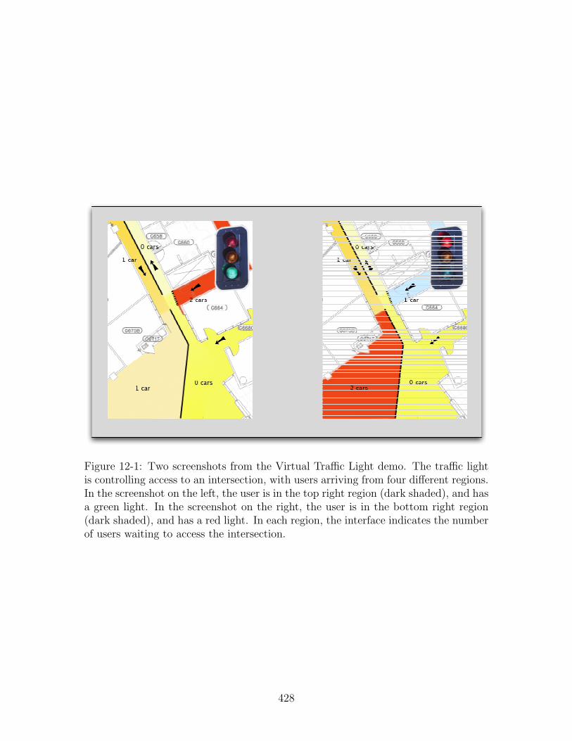
Figure 12-1: Two screenshots from the Virtual Traffic Light demo. The traffic lightis controlling access to an intersection, with users arriving from four different regions.In the screenshot on the left, the user is in the top right region (dark shaded), and hasa green light. In the screenshot on the right, the user is in the bottom right region(dark shaded), and has a red light. In each region, the interface indicates the numberof users waiting to access the intersection.
428

Figure 12-2: Virtual Traffic Light: Virtual Node and Client Routines
Main routine executing on the virtual node:
def msgReceived(self, msg):
replyArray = []
if msg.msgtype(msg) == "UPDATE":
self.UpdateVehInfo(msg)
self.UpdateLightState()
reply = "STATUS:" + self._statusSTR_()
replyArray.append(reply)
return replyArray
Main routine executing on the client:
while (self.running):
transmit-msg = self.createUpdateMessage()
self.sock.bcast(transmit-msg)
while self.sock.select() :
rcv-msg = self.sock.recv()
self.UpdateUI(rcv-msg)
if self.location.moved() :
self.UpdateUI(self.location.position)
429
Finally, in Section 12.3.3 we discuss some of the interesting algorithmic questionsthat remain.
12.3.1 Virtual Infrastructure Applications
In this section, we briefly overview some of the applications that we have considereddeveloping on the virtual infrastructure platform.
Traffic Control. Recall from Section 12.2.2 that we have already begun to im-plement a simple traffic control system on our prototype virtual infrastructure. Ascurrently implemented, the system supports virtual traffic lights that can control theflow of traffic at specific intersections. There are many possible extensions to thissimple system. For example, the virtual traffic lights at different intersections couldcoordinate to improve the flow of traffic. Moreover, the traffic control system couldnotify cars of upcoming traffic, and could help to route cars around congested regions.
Air Traffic Control. A natural extension to the problem of highway traffic con-trol is the problem of air traffic control. Currently, airplane traffic follows a strictset of rules: flight plans must be filed in advance, deviation from flight plans is notallowed, and problems of congestion—for example, during arrival and departure fromairports—are handled via human air traffic controllers. As air traffic has grown, how-ever, this system has become both increasingly inefficient and increasingly susceptibleto human error; we focus here on the problem of inefficiency. (Other work, e.g., [100],has considered solutions to minimize the problems of human error, particularly withrespect to take-off and landing.) As an example, pilots are often requires to fly longer(and hence more expensive) routes, since routes are statically assigned prior to flighttime; they are not allowed to switch to a shorter unoccupied route.
Thus the idea of free flight has been proposed: each airplane chooses its own routeindependently, and coordinates with nearby planes to avoid collisions. The challengelies in facilitating this coordination in a manner that allows for pilots to chooseefficient routes, while at the same time avoiding the potential for in-air collisions. Ithas been proposed in [15] that an air-traffic control system could be readily built on avirtual infrastructure platform. The three-dimensional space in which planes fly canbe divided into regions, each of which is associated with a virtual node. The virtualnodes are responsible for coordinating the flight plans of airplanes within their region,and for coordinating with nearby virtual nodes to ensure a safe flight plan.
Emergency Management and Rescue Worker Coordination. A third coor-dination scenario involves the management of an emergency situation, for example,an earthquake, a power blackout, or a terrorist attack. In such situations, emergencyworkers must coordinate to rescue survivors, restore order, and otherwise amelioratethe problems—while simultaneously ensuring the safety of the rescuers themselves.Moreover, the catastrophic event itself may have destroyed the infrastructure required
430

for the rescue workers to coordinate. Thus virtual infrastructure seems ideal for fa-cilitating the rescue effort.
There are a variety of other benefits provided by virtual infrastructure in this con-text. First, it is possible that some infrastructure may have survived the catastrophe;the virtual infrastructure implementation can take advantage of any remaining infras-tructure, while ensuring that virtual infrastructure is available even in regions wherethe infrastructure has been destroyed. Moreover, this process occurs transparently,and the rescue workers need not be aware of whether the previous infrastructureremains or was destroyed. Second, in the future, rescue workers may make use ofrobots and other mechanical devices to avoid putting the rescuers themselves in dan-gerous situations. Lynch et al. [69] have already begun to study the problem of usingvirtual infrastructure to coordinate mobile robots. Third, virtual infrastructure isclosely tied to geography, which may be particularly useful in coordinating rescueefforts. For example, rescue workers may want to associate certain information withparticular locations, say, warning any rescue worker that approaches of some danger.
Monitoring and Data Collection. Sensor and mobile networks are often de-ployed for the purpose of environmental monitoring and data collection. For example,in the ZebraNet project (see, e.g., [43]), mobile devices were attached to zebras inKenya and used to monitor the zebra behavior. Others have proposed the idea ofusing submergible and floating sensors to monitor aquatic environments. In thesesituations, little infrastructure is available, and it remains difficult to aggregate andcollect the data that has been collected by these sensors. Virtual infrastructure mayprovide a simple method to accomplish these tasks.
Internet Routing. Finally, we have recently begun to consider whether virtualinfrastructure can be used to facilitate internet routing in mobile networks. Specif-ically, virtual nodes can be used to execute simple IPv6 routers, transforming anunstructured wireless network into a well-defined network with a more traditionalstructure.
12.3.2 Trade-offs in Implementing Virtual Infrastructure
There are a variety of trade-offs that arise in implementing virtual infrastructure. Inthis section, we discuss some of these issues, along with some of the other challengesthat arise in practical implementations.
Notice that some of the applications discussed in Section 12.3.1 require highreliability—for example, air traffic control—while others can tolerate more faults—for example, data collection. Similarly, some applications—again, particularly thecontrol-related applications—require strong semantics, while others—for example,IPv6 routing—can tolerate weaker best-effort semantics. When implementing virtualinfrastructure, there is an inherent trade-off between (1) the efficiency (and simplicity)of the implementation, (2) the semantics of the virtual devices, and (3) the reliabilityand availability of the virtual infrastructure.
431

In the first part of this thesis, we described virtual infrastructure layers that havestrong semantics, and also provide good reliability. Specifically, the semantics ofthe virtual nodes emulated in Chapter 5 are defined simply in terms of traditionalcomputing devices: the virtual nodes behave exactly as real computing devices inwhich each step of computation is executed in order. In addition, the virtual nodesare available as long as there are any clients in the virtual node region, with onlyminimal overlap required when clients enter and leave the region. In order to ensurethese strong semantics and good reliability, the emulation sacrifices some efficiency:it depends on a totally-ordered broadcast service that guarantees reliable messagedelivery, which can be costly to implement; and it involves broadcasting redundantmessages to coordinate the replicas.
In the second part of this thesis, we describe a virtual infrastructure emulation thatalso provides strong semantics, but provides more limited availability. Specifically, thevirtual nodes are themselves prone to collisions and lost messages, and during timeswhen the network is congested, the virtual nodes may not be available. As a result,the virtual infrastructure emulation presented in Chapter 10 is more efficient: theunderlying broadcast service is less powerful, subject to congestion and lost messages;we can better bound the size of messages and the overhead of the emulation afterstabilization; we can bound the length of time necessary to emulate a virtual round,even during unstable portions of the execution. Moreover, there may be furtheroptimizations (as discussed in Section 12.3.3) that improve the performance of thisemulation algorithm.
For some applications, such as implementing an IPv6 router, however, weakersemantics are sufficient. In particular, IP routing guarantees only best effort messagedelivery, and hence some unexpected behavior may be acceptable. Moreover, lowerlevels of reliability may be sufficient: if a virtual router resets itself on occasion, thereis little effect on the resulting routing performance. Thus it seems likely that thereare quite efficient emulation algorithms that are sufficient for implementing virtualrouters. It remains an interesting question to consider virtual infrastructure withweaker semantics.
Another interesting trade-off that arises in the use of virtual infrastructure isthe question of how much infrastructure is needed. Each piece of infrastructure hassome cost—in terms of emulation—and provides some benefit—in terms of simplifyingcoordination among the clients.
For example, in the case of virtual traffic control, it may be necessary to havea virtual traffic light at each intersection, and it may optionally be useful to havesome additional virtual nodes in between intersections to help coordinate the trafficand provide information to passing vehicles. Similarly, as discussed in Section 3.3,when using virtual nodes for routing or data collision, there is a trade-off between thenumber of virtual nodes and the performance of the routing and data collection: themore virtual nodes, the lower the latency for delivering messages or aggregated data,but the higher the cost.
Clearly, optimizing this trade-off depends significantly on the efficiency of thevirtual infrastructure emulation—which itself depends on the desired semantics andreliability of the virtual entities.
432
Another interesting problem is the dynamic control of the amount of virtual infras-tructure. This would allow the system to dynamically adjust this trade-off, changingthe number of virtual nodes or objects, depending, perhaps, on the desired perfor-mance. In Chapter 6, the quorum-based protocol is reconfigurable, meaning that theset of virtual objects that the protocol uses may be dynamically changed; in thiscase, there is no reason to emulate the virtual objects that are currently unused. Weexamine one aspect of this question in [34], where (autonomous) virtual nodes maybe generated and destroyed on the fly.
Finally, it remains an interesting open question—and an important area of ongoingresearch—to compare the performance and complexity of algorithms based on virtualinfrastructure with the algorithms implemented directly on mobile ad hoc networks.
12.3.3 Algorithmic Open Questions
There are a variety of algorithmic questions involved in designing better and moreefficient virtual infrastructure. In this section, we discuss several of these possibilities.
First, in the context of collision-prone networks, there are several optimizationsthat can further improve the performance of the emulation algorithm in Chapter 10.It seems likely that the overhead of the emulation can be further reduced: there is noneed to include the client and virtual node messages (from the client and vn phases) inthe ballot (send in the scheduled-ballot and unscheduled-ballot phase); in this case, theoverhead of the emulation after stabilization—aside from nodes joining and leaving—is reduced to an additive constant per round. It also remains open as to whether itis possible to reduce the number of rounds required to implement one virtual round:as presented in this thesis, the length of a virtual round depends on the size of theschedule; it may be possible to implement one virtual round in a constant numberof underlying rounds, independent of the size of the schedule. Finally, it remainsan open question as to whether there is a simpler algorithm for emulating virtualinfrastructure in collision-prone networks.
Second, there remain a variety of questions related to the problem of collision de-tection. In this thesis, we have assumed that mobile nodes have access to complete,eventually accurate collision detectors. In other work [23, 79], we have consideredmajority-complete collision detectors and zero-complete collision detectors. We be-lieve that it is possible to adapt the emulation algorithm in Chapter 10 to toleratemajority-complete collision detection. By contrast, we believe that it is impossible toemulate virtual infrastructure with bounded round length using zero-complete colli-sion detectors. It also remains an open question as to which collision detectors canbe reliably built in wireless radio hardware. Perfect completeness seems unrealistic,while zero-complete collision detectors appear more plausible. It is possible, however,that all real collision detectors may occasionally fail, and hence it may be interest-ing to consider probabilistic completeness conditions. There remains much work inimplementing and experimenting with various collision detectors.
Third, there also remain a variety of questions related to the problem of contentionmanagement. Most contention managers depend on backoff protocols to reduce con-tention, and there has been a large body of literature studying the problem of backoff.
433

It remains an interesting question to consider the performance of backoff protocolsin the context of fault-prone collision detectors. Specifically, most backoff protocolsassume that the mobile nodes can accurate detect collisions. When the collision detec-tors may be unreliable, the problem of contention management may be more involved.It also remains an open question whether we can emulate virtual infrastructure usingeven weaker contention managers.
Fourth, mobile nodes tend to have very stringent energy limitations. They havesmall batteries, and a limited lifetime that is further shortened by broadcast trans-missions that are costly, in terms of energy. It is possible to take advantage of theredundancy already built into virtual infrastructure emulation to increase the lifetimeof a wireless network. Specifically, the various replicas for a virtual node can sharethe energy cost of the emulation, potentially improving the lifetime of the entire net-work. Designing an energy-optimal virtual infrastructure emulation remains an openarea of research, as does determining the potential energy costs and benefits of usingvirtual infrastructure.
Finally, the problem of malicious (or Byzantine) devices remains an area of ongoingresearch. Specifically, is it possible to emulate virtual infrastructure in the presenceof non-cooperative devices? If the malicious devices themselves can cause arbitrarycollisions, then clearly it is impossible for replicas to coordinate. Malicious devices,however, may have some limited capacity to disrupt the network, either due to energylimitations, or due to the existence of multiple disjoint frequencies that can be usedby the replicas to communicate. In this context, it seems likely the replicas cancommunicate sufficiently to emulate virtual infrastructure. Further, however, it maydesirable that the malicious devices learn nothing of the state of the virtual system.Cryptographic techniques related to secret sharing and secure function evaluationmay enable such scenarios.
434

Bibliography
[1] IEEE 802.11. Wireless LAN MAC and physical layer specifications, June 1999.
[2] Ittai Abraham, Danny Dolev, and Dahlia Malkhi. LLS: a locality aware locationservice for mobile ad hoc networks. In DIALM-POMC, pages 75–84, 2004.
[3] N. Alon, L. Babai, and A. Itai. A fast and simple randomized parallel algorithmfor the maximal independent set problem. Journal of Algorithms, 7(4):567–583,1986.
[4] N. Alon, A. Bar-Noy, N. Linial, and D. Peleg. On the complexity of radiocommunication. In STOC ’89: Proceedings of the twenty-first annual ACMsymposium on Theory of computing, pages 274–285. ACM Press, 1989.
[5] Yair Amir. Replication Using Group Communication Over a Partitioned Net-work. PhD thesis, Hebrew University, 1995.
[6] Paul Attie, Nancy A. Lynch, and Sergio Rajsbaum. Boosting fault-tolerance inasynchronous message passing systems is impossible. Technical Report LCS-TR-877, MIT, 2002.
[7] Ziv Bar-Joseph, Idit Keidar, and Nancy A. Lynch. Early-delivery dynamicatomic broadcast. In DISC, pages 1–16, London, UK, 2002. Springer-Verlag.
[8] Ziv Bar-Joseph, Idit Keidar, and Nancy A. Lynch. Early-delivery dynamicatomic broadcast. In DISC ’02: Proceedings of the 16th International Confer-ence on Distributed Computing, pages 1–16, London, UK, 2002. Springer-Verlag.
[9] R. Bar-Yehuda, O. Goldreich, and A. Itai. Efficient emulation of single-hop radionetwork with collision detection on multi-hop radio network with no collisiondetection. Distributed Computing, 5:67–71, 1991.
[10] R. Bar-Yehuda, O. Goldreich, and A. Itai. On the time-complexity of broadcastin multi-hop radio networks: An exponential gap between determinism andrandomization. Journal of Computer and System Sciences, 45(1):104–126, 1992.
[11] Jacob Beal. Persistent nodes for reliable memory in geographically local net-works. Technical Report AIM-2003-11, MIT, 2003.
435

[12] Jacob Beal. A robust amorphous hierarchy from persistent nodes. In Proc. ofCommunication Systems and Networks, 2003.
[13] R. Braden. Requirements for Internet Hosts - Communication Layers. RFC1122 (Standard), October 1989. Updated by RFC 1349.
[14] Matthew Brown, Seth Gilbert, Nancy Lynch, Calvin Newport, Tina Nolte, andMichael Spindel. The virtual node layer: A programming abstraction for wire-less sensor networks. In International Workshop on Wireless Sensor NetworkArchitecture, April 2007.
[15] Matthew D. Brown. Air traffic control using virtual stationary automata. Mas-ter’s thesis, MIT, September 2007.
[16] Costas Busch, Malik Magdon-Ismail, Fikret Sivrikaya, and Bulent Yener.Contention-free MAC protocols for wireless sensor networks. In Rachid Guer-raoui, editor, Proceedings of 18th International Symposium on Distributed Com-puting, volume 3274/2004 of Lecture Nodes in Computer Science, pages 245–259, Oct 2004.
[17] T. Camp and Y. Liu. An adaptive mesh-based protocol for geocast routing.Journal of Parallel and Distributed Computing: Special Issue on Mobile Ad-hocNetworking and Computing, pages 196–213, 2002.
[18] Paz Carmi, Shlomi Dolev, Sariel Har-Peled, Matthew J. Katz, and MichaelSegal. Geographic quorum system approximations. Algorithmica, 41(4):233–244, 2005.
[19] Miguel Castro and Barbara Liskov. Practical byzantine fault tolerance andproactive recovery. ACM TOCS, 20(4):398–461, 2002.
[20] Ioannis Chatzigiannakis, Sotiris Nikoletseas, and Paul Spirakis. An efficientcommunication strategy for ad-hoc mobile networks. In Proc. 15th InternationalSymp. on Distributed Computing, pages 285 – 299, 2001.
[21] B. Chlebus and D. Kowalski. A better wake-up in radio networks. PODC, pages266–274, 2004.
[22] B. S. Chlebus, L. Gasieniec, A. Gibbons, A. Pelc, and W. Rytter. Deterministicbroadcasting in ad hoc radio networks. Distributed Computing, 15(1):27–38,2002.
[23] G. Chockler, M. Demirbas, S. Gilbert, C. Newport, and T. Nolte. Consensusand collision detectors in wireless ad hoc networks. In PODC, 2005. To appear.
[24] G. V. Chockler, N. Huleihel, and D. Dolev. An adaptive totally ordered mul-ticast protocol that tolerates partitions. In PODC ’98: Proceedings of the sev-enteenth annual ACM symposium on Principles of distributed computing, pages237–246, New York, NY, USA, 1998. ACM Press.
436

[25] A. Clementi, A. Monti, and R. Silvestri. Round robin is optimal for fault-tolerant broadcasting on wireless networks. J. Parallel Distributed Computing,64(1):89–96, 2004.
[26] M. de Berg, M. van Kreveld, M. Overmars, and O. Schwarzkopf. ComputationalGeometry: Algorithms and Applications. Springer-Verlag, 2nd edition, 2000.
[27] J. Deng, P. K. Varshney, and Z. J. Haas. A new backoff algorithm for theIEEE 802.11 distributed coordination function. In Communication Networksand Distributed Systems Modeling and Simulation, January 2004.
[28] S. Dolev, E. Schiller, and J. Welch. Random walk for self-stabilizing groupcommunication in ad-hoc networks. In Proc. of the 21st IEEE Symp. on ReliableDistributed Systems, pages 70–79, 2002.
[29] Shlomi Dolev, Seth Gilbert, Limor Lahiani, Nancy A. Lynch, and Tina Nolte.Timed virtual stationary automata for mobile networks. In Proceeding ofthe 43rd Allerton Conference on Communication, Control, and Computing,September 2005. Invited.
[30] Shlomi Dolev, Seth Gilbert, Limor Lahiani, Nancy A. Lynch, and Tina Nolte.Timed virtual stationary automata for mobile networks. In 9th InternationalConference on Principles of Distributed Systems (OPODIS), December 2005.
[31] Shlomi Dolev, Seth Gilbert, Nancy A. Lynch, Elad Schiller, Alex A. Shvarts-man, and Jennifer L. Welch. Virtual mobile nodes for mobile adhoc networks.In Proceeding of the 18th International Conference on Distributed Computing(DISC), October 2004.
[32] Shlomi Dolev, Seth Gilbert, Nancy A. Lynch, Alex A. Shvartsman, and JenniferWelch. Geoquorums: Implementing atomic memory in mobile ad hoc networks.In Proceeding of the 17th International Conference on Distributed Computing(DISC), volume 2848 of Lecture Notes in Computer Science, October 2003.
[33] Shlomi Dolev, Seth Gilbert, Nancy A. Lynch, Alex A. Shvartsman, and JenniferWelch. Geoquorums: Implementing atomic memory in mobile ad hoc networks.Distributed Computing, 18(2):125–155, November 2005.
[34] Shlomi Dolev, Seth Gilbert, Elad Schiller, Alex A. Shvartsman, and Jennifer L.Welch. Autonomous virtual mobile nodes. In Proceeding of the 3rd Workshopon Foundations of Mobile Computing (DIAL-M-POMC), September 2005.
[35] Shlomi Dolev, Limor Lahiani, Nancy Lynch, and Tina Nolte. Self-stabilizingmobile node location management and message routing. In SSS, 2005.
[36] Alan Fekete, Nancy Lynch, and Alex Shvartsman. Specifying and using a parti-tionable group communication service. In PODC, pages 53–62, New York, NY,USA, 1997. ACM Press.
437
[37] D. Ganesan, B. Krishnamachari, A. Woo, D. Culler, D. Estrin, and S. Wicker.Complex behavior at scale: An experimental study of low-power wireless sensornetworks. UCLA Computer Science Technical Report UCLA/CSD-TR, 2003.
[38] Seth Gilbert, Nancy A. Lynch, and Alex A. Shvartsman. RAMBO II: Rapidlyreconfigurable atomic memory for dynamic networks. In Proceedings of theInternational Conference on Dependable Systems and Networks (DSN), June2003.
[39] Ben Greenstein, Eddie Kohler, and Deborah Estrin. A sensor network appli-cation construction kit (snack). In 2nd international conference on Embeddednetworked sensor systems, 2004.
[40] Kostas P. Hatzis, George P. Pentaris, Paul G. Spirakis, Vasilis T. Tampakas,and Richard B. Tan. Fundamental control algorithms in mobile networks. InProc. of the 1st ACM Symp. on Parallel Algorithms and Architectures archive,pages 251 – 260, Saint Malo, France, 1999.
[41] Ted Herman and Sebastien Tixeuil. A distributed tdma slot assignment algo-rithm for wireless sensor networks. In Proceedings of the First InternationalWorkshop on Algorithmic Aspects of Wireless Sensor Networks, volume 3121 ofLecture Notes in Computer Science, 2004.
[42] David B. Johnson, David A. Maltz, and Josh Broch. DSR: The Dynamic SourceRouting Protocol for Multi-Hop Wireless Ad Hoc Networks, chapter 5, pages139–172. Addison-Wesley, 2001.
[43] Philo Juang, Hidekazu Oki, Yong Wang, Margaret Martonosi, Li-Shiuan Peh,and Daniel Rubenstein. Energy-efficient computing for wildlife tracking: designtradeoffs and early experiences with zebranet. In ASPLOS, pages 96–107, 2002.
[44] Brad Karp and H. T. Kung. GPSR: greedy perimeter stateless routing forwireless networks. In Mobile Computing and Networking, pages 243–254, 2000.
[45] Dilsun Kirli Kaynar, Nancy Lynch, Roberto Segala, and Frits Vaandrager. Thetheory of timed I/O automata. Technical Report MIT-LCS-TR-917a, MIT, apr2004.
[46] Dilsun Kirli Kaynar, Nancy Lynch, Roberto Segala, and Frits Vaandrager. TheTheory of Timed I/O Automata. Synthesis Lectures on Computer Science.Morgan & Claypool, 2006.
[47] Idit Keidar and Danny Dolev. Increasing the resilience of atomic commit at noadditional cost. In PODS, pages 245–254, 1995.
[48] Idit Keidar and Danny Dolev. Efficient message ordering in dynamic networks.In PODC ’96: Proceedings of the fifteenth annual ACM symposium on Princi-ples of distributed computing, pages 68–76, New York, NY, USA, 1996. ACMPress.
438
[49] Idit Keidar and Danny Dolev. Broadcast in the face of network partitions:Exploiting group communication for replication in partitionable networks. InD. Avresky, editor, Dependable Network Computing, chapter 3. Kluwer Aca-demic Publications, 2000.
[50] Young Bae Ko and Nitin Vaidya. Geotora: A protocol for geocasting in mobilead hoc networks. In Proc. of the IEEE Intl. Conference on Network Protocols,pages 240–249, November 2000.
[51] D. Kotz, C. Newport, R. S. Gray, J. Liu, Y. Yuan, and C. Elliott. Experimentalevaluation of wireless simulation assumptions. In Proceedings of the 7th ACMinternational symposium on Modeling, analysis and simulation of wireless andmobile systems, pages 78–82, 2004.
[52] D. Kotz, C. Newport, R. S. Gray, J. Liu, Y. Yuan, and C. Elliott. Experimentalevaluation of wireless simulation assumptions. In Proceedings of the ACM/IEEEInternational Symposium on Modeling, Analysis and Simulation of Wireless andMobile Systems (MSWiM), pages 78–82, October 2004.
[53] E. Kranakis, D. Krizanc, and A. Pelc. Fault-tolerant broadcasting in radionetworks. In ESA ’98: Proceedings of the 6th Annual European Symposium onAlgorithms, pages 283–294, 1998.
[54] F. Kuhn, R. Wattenhofer, and A. Zollinger. Asymptotically optimal geomet-ric mobile ad-hoc routing. In Proceedings of the International Workshop onDiscrete Algorithms and Methods for Mobile Computing and Communications(Dial-M), pages 24–33, 2002.
[55] Fabian Kuhn, Thomas Moscibroda, and Roger Wattenhofer. Radio networkclustering from scratch. In 12nd Annual European Symposium on Algorithms,September 2004.
[56] Fabian Kuhn, Roger Wattenhofer, and Aaron Zollinger. Worst-case optimaland average-case efficient geometric ad-hoc routing. In Proceedings of the 4thInternational Symposium on Mobile Ad-Hoc Networking and Computing, 2003.
[57] Leslie Lamport. The implementation of reliable distributed multiprocess sys-tems. Computer Networks, 2:95–114, 1978.
[58] Leslie Lamport. Time, clocks, and the ordering of events in a distributed system.Comm. of the ACM, 21(7):558–565, 1978.
[59] Leslie Lamport. Time, clocks, and the ordering of events in a distributed system.Communications of the ACM, 21(7):558–565, july 1978.
[60] Leslie Lamport. The part-time parliament. ACM Transactions on ComputerSystems, 16(2):133–169, 1998.
439

[61] Leslie Lamport. The part-time parliament. ACM Transactions on ComputerSystems, 16(2):133–169, 1998.
[62] Leslie Lamport. Paxos made simple. ACM SIGACT News, 32(4):18–25, 2001.
[63] Butler W. Lampson. How to build a highly available system using consensus.In WDAG, pages 1–17, London, UK, 1996. Springer-Verlag.
[64] Philip Lewis and David Culler. Mate: a tiny virtual machine for sensor net-works. In International Conference on Mobile Computing and Networks, 2000.
[65] J. Li, J. Jannotti, D.S.J. De Couto, D.R. Karger, and R. Morris. A scalablelocation service for geographic ad hoc routing. In Proceedings of Mobicom, 2000.
[66] Q. Li and D. Rus. Sending messages to mobile users in disconnected ad-hocwireless networks. In Proc. of the 6th MobiCom, 2000.
[67] M. Luby. A simple parallel algorithm for the maximal independent set problem.SIAM Journal on Computing, 15:1036–1053, 1986.
[68] J. Luo and J. Hubaux. NASCENT: Network layer service for vicinity ad-hocgroups. In SECON, 2004.
[69] Nancy Lynch, Sayan Mitra, and Tina Nolte. Motion coordination using virtualnodes. Technical report, MIT CSAIL, 2005.
[70] Nancy A. Lynch. Distributed Algorithms. Morgan Kaufman, 1996.
[71] Nancy A. Lynch, Roberto Segala, and Frits Vaandraager. Hybrid I/O automata.Information and Computation, 185(1), August 2003.
[72] Nancy A. Lynch, Roberto Segala, and Frits Vaandraager. Hybrid I/O automata.Technical Report LCS-TR-827d, MIT, August 2003.
[73] Nancy A. Lynch and Alex A. Shvartsman. RAMBO: A reconfigurable atomicmemory service for dynamic networks. In Proc. of the 16th Intl. Symp. onDistributed Computing, pages 173–190, 2002.
[74] N. Malpani, J. Welch, and Vaidya. Leader election algorithms for mobile adhoc networks. In ACM DIAL-M, 2000.
[75] M. Merritt, F. Modugno, and M.R. Tuttle. Time constrained automata. InCONCUR, pages 408–423, 1991.
[76] Koji Nakano and Stephan Olariu. A survey on leader election protocols forradio networks. In ISPAN, page 71. IEEE Computer Society, 2002.
[77] Badri Nath and Dragos Niculescu. Routing on a curve. ACM SIGCOMMComputer Communication Review, 33(1):150 – 160, January 2003.
440

[78] J. C. Navas and T. Imielinski. Geocast – geographic addressing and routing. InProc. of the 3rd MobiCom, pages 66–76, 1997.
[79] Calvin Newport. Consensus and collision detectors in wireless ad hoc networks.Master’s thesis, MIT, 2006.
[80] Ryan Newton, Arvind, and Matt Welsh. Building up to macroprogramming: Anintermediate language for sensor networks. In Fourth International Conferenceon Information Processing in Sensor Networks, 2005.
[81] Ryan Newton and Matt Welsh. Region streams: Functional macroprogrammingfor sensor networks. In First international workshop on data management forsensor networks, 2004.
[82] Tina Nolte. Virtual Stationary Timed Automata for Mobile Networks. PhDthesis, MIT.
[83] Tina Nolte and Nancy Lynch. A virtual node-based tracking algorithm formobile networks. In Proceedings of International Conference on DistributedComputing Systems, June 2007.
[84] V. Park and M.S. Corson. A highly adaptive distributed routing algorithm formobile wireless networks. In IEEE INFOCOM, April 1997.
[85] Charles E. Perkins and Elizabeth M. Royer. Ad hoc on-demand distance vectorrouting. In 2nd IEEE Workshop on Mobile Computing Systems and Applica-tions, pages 90–100, February 1999.
[86] J. Polastre and D. Culler. Versatile low power media access for wireless sensornetworks. In Embedded Networked Sensor Systems, 2004.
[87] Joseph Polastre, Robert Szewczyk, Cory Sharp, and David Culler. The moterevolution: Low power wireless sensor network devices. In Hot Chips 16: ASymposium on High Performance Chips, 2004.
[88] J. Postel. Internet Protocol. RFC 791 (Standard), September 1981. Updatedby RFC 1349.
[89] J. Postel. Transmission Control Protocol. RFC 793 (Standard), September1981. Updated by RFC 3168.
[90] Nissanka B. Priyantha, Anit Chakraborty, and Hari Balakrishnan. The cricketlocation-support system. In Proc. of the 6th MobiCom, pages 32–43, August2000.
[91] S. Ratnasamy, B. Karp, L. Yin, F. Yu, D. Estrin, R. Govindan, and S. Shenker.GHT: A geographic hash table for data-centric storage. In First ACM Workshopon Wireless Sensor Networks and Applications, 2002.
441
[92] Y. Rekhter and T. Li. A Border Gateway Protocol 4 (BGP-4). RFC 1771 (DraftStandard), March 1995.
[93] Elizabeth M. Royer and Charles E. Perkins. Multicast operation of the adhoc on-demand distance vector routing protocol. In MobiCom, pages 207–218,August 1999.
[94] Fred B. Schneider. Implementing fault-tolerant services using the state machineapproach: a tutorial. ACM Computing Surveys, 22(4):299–319, 1990.
[95] Dale Skeen. Nonblocking commit protocols. In SIGMOD Conference, pages133–142, 1981.
[96] Dale Skeen. A quorum-based commit protocol. In Berkeley Workshop, pages69–80, 1982.
[97] Mike Spindel. Title unknown. Master’s thesis, MIT.
[98] Qixiang Sun and Hector Garcia-Molina. Using ad-hoc inter-vehicle networksfor regional alerts. Technical report, Stanford, oct 2004.
[99] Daniela Tulone. Is it possible to ensure strong data guarantees in highly mobilenetworks? In Proceedings of the Fifth Annual Mediterranean Ad Hoc Network-ing Workshop, pages 294–301, June 2006.
[100] Shinya Umeno and Nancy A. Lynch. Safety verification of an aircraft landingprotocol: A refinement approach. In Hybrid Systems: Computation and Control(HSCC), pages 557–572, 2007.
[101] T. van Dam and K. Langendoen. An adaptive energy-efficient MAC protocolfor wireless sensor networks. In In Proceedings ACM Conference on EmbeddedNetworked Sensor Systems (SenSys 2003), 2003.
[102] J. Walter, J. Welch, and N.H. Vaidya. A mutual exclusion algorithm for ad hocmobile networks. Wireless Networks, 7(6):585–600, 2001.
[103] Matt Welsh and Geoff Mainland. Programming sensor networks using abstractregions. In First USENIX Symposium on Networked Systems Design and Im-plementation, 2004.
[104] Kamin Whitehouse, Cory Sharp, Eric Brewer, and David Culler. Hood: aneighborhood abstraction for sensor networks. In International conference onmobile systems, applications, and services, 2004.
[105] A. Woo, T. Tong, and D. Culler. Taming the underlying challenges of multihoprouting in sensor networks. In Proceedings of the First ACM Conference onEmbedded Networked Sensor Systems, 2003.
442

[106] A. Woo, K. Whitehouse, F. Jiang, J. Polastre, and D. Culler. The shadowingphenomenon: implications of receiving during a collision. Technical ReportUCB//CSD-04-1313, UC Berkeley, March 2004.
[107] W. Ye, J. Heidemann, and D. Estrin. An energy-efficient MAC protocol forwireless sensor networks. In In Proceedings of the 21st International AnnualJoint Conference of the IEEE Computer and Communications Societies (IN-FOCOM 2002), 2002.
[108] J. Zhao and R. Govindan. Understanding packet delivery performance in densewireless sensor networks. In Proceedings of the First ACM Conference on Em-bedded Networked Sensor Systems, 2003.
443

444

Appendix A
Background Material
In this chapter, we review some basic concepts and notation that are used throughoutthis thesis. More details can be found in [45,46,70].
A.1 Basic Notation
• Let ⊥ be some distinguished symbol. For any set X, we refer to the set X∪{⊥}as X⊥. For example, if msgs is a set of messages, then msgs⊥ is the set ofmessages plus ⊥.
• For any execution α, `time(α) refers to the last time in the execution.
• For any finite execution α, `state(α) refers to the last state in the execution.
A.2 Timed I/O Automata
In this section, we review some of the basic theory of timed automata. See [45, 46]for more detail. A timed I/O automaton (TIOA) is a tuple
〈vars , states , start , actions , input , output , δ, trajectories〉
that is input enabled (Definition A.2.4) and time-passage enabled (Definition A.2.5).In more detail, an I/O automaton consists of the following components:
• vars , a set of internal variables,
• states ⊆ vals(vars), the set of states for the automaton,
• start ⊆ states , a subset of states in which the automaton may begin an execu-tion,
• actions , a set of actions that name transitions,
• input ⊆ actions , a subset of actions designated as input actions,
445

• output ⊆ actions , a subset of actions designated as output actions; output ∩input = ∅,
• δ ⊆ states × actions × states , a transition relation that determines how theactions modify the state,
• trajectories ⊆ trajs(states), a set of trajectories defining how the analog vari-ables evolve as time passes in between discrete actions. (The set trajs(states)describes all possible trajectories over the set of states.) The trajectories mustsatisfy the following axioms:
– (Existence of point trajectories.) If x ∈ states , then the point trajectorywith domain [0, 0] mapping 0 to x is in trajectories .
– (Prefix closure.) For every τ ∈ trajectories and every τ ′ ≤ τ , τ ′ ∈trajectories .
– (Suffix closure.) For every τ ∈ trajectories and every t ∈ domain(τ),τ D t ∈ trajectories , i.e., every extension of trajectory τ is also in the setof trajectories.
– (Concatenation closure.) Let τ0, τ1, τ2, . . . be a sequence of trajectories intrajectories such that for each nonfinal index i, τi is closed and τi.lstate =τi+1.fstate. Then τ0 a τ1 a · · · ∈ trajectories , i.e., the concatenation oftrajectories is also in the set of trajectories.
Definition A.2.1. An action a ∈ actions is an external action if it is an input oran output actions, that is, a ∈ input ∪ output.
Definition A.2.2. An action a ∈ actions is an internal action if it is not anexternal action.
Definition A.2.3. An action a ∈ actions is locally controlled if it is an internalor an output action, that is, a /∈ input.
By assumption, a timed-I/O automaton is input enabled:
Definition A.2.4. An automaton is input enabled if for each state s ∈ states anda ∈ input, there exists a s′ ∈ states such that 〈s, a, s′〉 ∈ δ.
Also by assumption, a timed-I/O automaton is time-passage enabled:
Definition A.2.5. An automaton is time-passage enabled if for each state s ∈states there exists τ ∈ trajectories such that τ.fstate = s and either
1. τ.ltime =∞ or
2. τ is closed and some locally controlled action ` is enabled in τ.lstate.
One subclass of timed I/O automata is the set of asynchronous automata:
446
Definition A.2.6. We say that a timed I/O automaton is asynchronous if all ofits variables are discrete and if its set of trajectories consists of all constant-valuedmappings from all possible time intervals.
An asynchronous automaton can have any possible time-passage between any twodiscrete events.
We will be interested in automata that take only a finite number of steps in afinite interval of time:
Definition A.2.7. We say that an execution fragment is locally Zeno if it has finitelimit time and contains infinitely many locally controlled actions.
Definition A.2.8. A timed I/O automaton is progressive if it has no locally Zenoexecution fragments.
In general, a progressive automaton guarantees to only take a finite number oflocally controlled actions in a bounded amount of time. While we will be interestedin overall systems that guarantee this property, some subcomponents of the systemmay have a weaker property: they will only provide this guarantee when there area finite number of input actions during the execution fragment in question. Wetherefore introduce here a new notion of progessivity:
Definition A.2.9. We say that a timed I/O automaton is internally progressive ifit has no locally Zeno execution fragments containing a finite number of input actions.
Composition is a key operation that combines two automata into a single automa-ton. In order to compose two automata, they must be “compatible:”
Definition A.2.10. We say that timed automata A1 and A2 are compatible if (1)the set of internal actions of A1 is disjoint from the actions of A2, (2) the set ofinternal actions of A2 is disjoint from the actions of A1, and (3) the variables of A1
and A2 are disjoint.
When two internally progressive TIOAs are composed together, there is no guar-antee with respect to the resulting automaton; it may in fact have Zeno executions.When one of the automata is progressive and the other is internally progressive, thenwe can state a theorem about their composition:
Theorem A.2.11. If A1 is a progressive TIOA, and A2 is an internally-progressiveTIOA, and A1 and A2 are compatible, then their composition is an internally-progressiveTIOA.
Proof. Assume that the composed automaton has a locally Zeno execution fragment.Therefore it contains infinitely many locally controlled actions. Notice that only afinite number of these locally controlled actions can be actions from automaton A1,since A1 is progressive. Thus the execution fragment must contain infinitely manylocally controlled actions from A2. Since A2 is internally-progressive, this implies thatthe execution fragment has an infinite number of actions that are either input actions
447

to the composed automaton or output actions of A1 that act as hidden inputs to A2.Since only a finite number of the actions are output actions from A1, this implies thatthere are an infinite number of input actions to the composed automaton, satisfyingthe requirements of an internally-progressive automaton.
We will often want to talk about restricting an execution to a particular au-tomaton, i.e., to a particular set of actions and variables. Given an execution α, a setof actions A, and a set of variables V , we denote by α|(A, V ) the (A, V )-restrictionof α.
Before defining (A, V )-restriction, we note the following notation: if f is a functionand S is a set, we donte by f |S the restriction of f to S, i.e., the function g withdom(g) = (dom(f) ∩ S) where g(c) = f(c) for each c ∈ dom(g); if f is a functionwhose range is a set of functions, and if S is a set, we indicate by f ↓ S the functiong where dom(g) = dom(f) and g(c) = f(c)|S for each c ∈ dom(g). (See [46], Section2.)
For any finite execution α, the (A, V )-restriction of α is defined inductively asfollows:
α|(A, V ) =
τ ↓ V α = τ
α′|(A, V ).a.(τ ↓ V ) α = (α′.a.τ), a ∈ Aα′|(A, V ).(τ ↓ V ) α = (α′.a.τ), a /∈ A
For infinite executions, then the (A, V )-restriction is simply the limit over all closedprefixes of α.
A.3 Atomic Objects
Atomic objects play an important role in the Virtual Object Model discussed in Part Iof this thesis. In this section, we first define a variable type (Appendix A.3.1), whichis used to specify an atomic object. As an example, we specify the variable type fora read/write object. We then formally describe an atomic object (Appendix A.3.2).Finally, we discuss what it means to implement an atomic object, and present a keytheorem that we later use to prove that the virtual objects are, in fact, atomic objects(Appendix A.3.3).
A.3.1 Variable Types
An atomic object is specified by a variable type that describes its sequential behavior.The definition presented here is adapted from [70], Chapter 9, and [6]. A variabletype τ consists of the following components:
• V , a set of legal values (i.e., states) for the object
• v0 ∈ V , an initial value (i.e., state) for the object
• invocations , a set of invocations
• responses , a set of responses
448
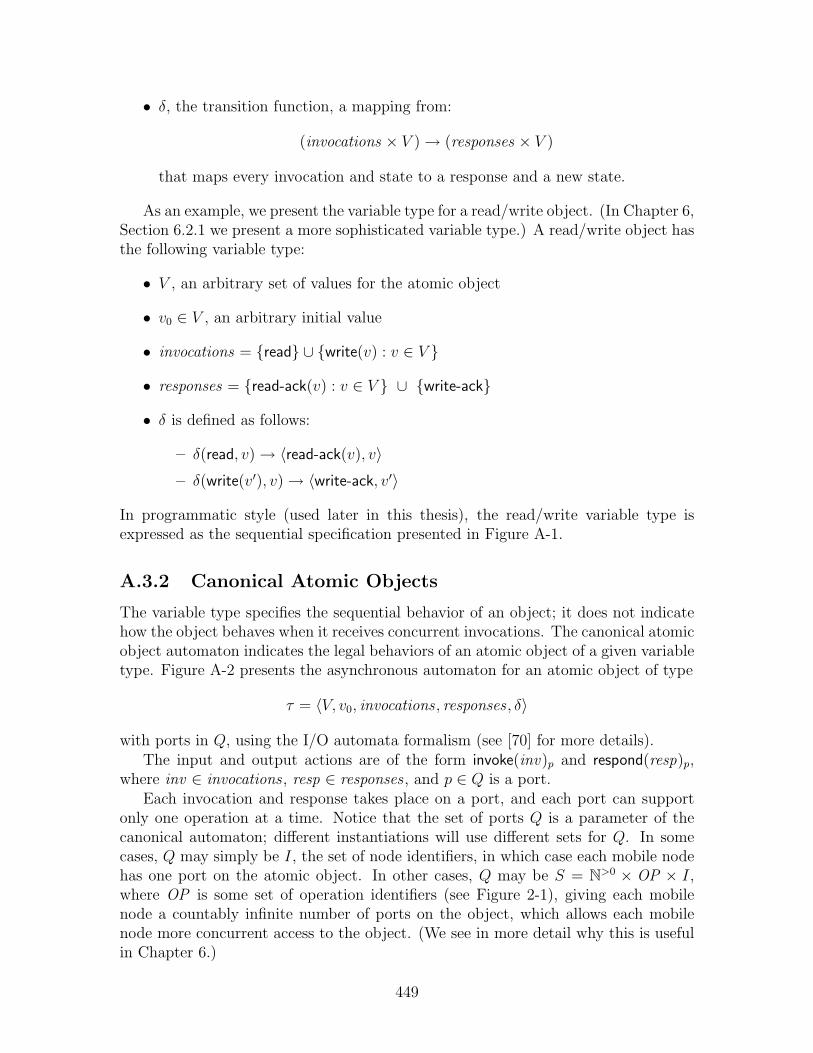
• δ, the transition function, a mapping from:
(invocations × V )→ (responses × V )
that maps every invocation and state to a response and a new state.
As an example, we present the variable type for a read/write object. (In Chapter 6,Section 6.2.1 we present a more sophisticated variable type.) A read/write object hasthe following variable type:
• V , an arbitrary set of values for the atomic object
• v0 ∈ V , an arbitrary initial value
• invocations = {read} ∪ {write(v) : v ∈ V }
• responses = {read-ack(v) : v ∈ V } ∪ {write-ack}
• δ is defined as follows:
– δ(read, v)→ 〈read-ack(v), v〉– δ(write(v′), v)→ 〈write-ack, v′〉
In programmatic style (used later in this thesis), the read/write variable type isexpressed as the sequential specification presented in Figure A-1.
A.3.2 Canonical Atomic Objects
The variable type specifies the sequential behavior of an object; it does not indicatehow the object behaves when it receives concurrent invocations. The canonical atomicobject automaton indicates the legal behaviors of an atomic object of a given variabletype. Figure A-2 presents the asynchronous automaton for an atomic object of type
τ = 〈V, v0, invocations , responses , δ〉
with ports in Q, using the I/O automata formalism (see [70] for more details).The input and output actions are of the form invoke(inv)p and respond(resp)p,
where inv ∈ invocations , resp ∈ responses , and p ∈ Q is a port.Each invocation and response takes place on a port, and each port can support
only one operation at a time. Notice that the set of ports Q is a parameter of thecanonical automaton; different instantiations will use different sets for Q. In somecases, Q may simply be I, the set of node identifiers, in which case each mobile nodehas one port on the atomic object. In other cases, Q may be S = N>0 × OP × I,where OP is some set of operation identifiers (see Figure 2-1), giving each mobilenode a countably infinite number of ports on the object, which allows each mobilenode more concurrent access to the object. (We see in more detail why this is usefulin Chapter 6.)
449

Figure A-1: Read/Write Sequential Specification.
1 State:2 value, initially v0
3
4 Operations:5 read()6 return read-ack(value)7
8 write(new-value)9 value ← new-value
10 return write-ack()
450

Figure A-2: Canonical Atomic Object Specification.Object Type τ = 〈V, v0, invocations, responses, δ〉 for the set Q of ports.
1 Signature:2 Input invoke(inv)p, inv ∈ invocations, p ∈ Q3
4 Output respond(resp)p, resp ∈ responses, p ∈ Q5
6 Internal perform(inv, v, resp, v′)p, inv ∈ invocations, resp ∈ responses, v,v′ ∈ V, p ∈ Q7
8 State:9 val ∈ V, a value, initially v0
10 inv-buffer, a set of pairs 〈inv, p〉, inv ∈ invocations, by port p, p ∈ Q, initially ∅11 resp-buffer, a set of pairs 〈resp, p〉, resp ∈ responses, to port p, p ∈ Q, initially ∅12
13 Transitions:14
15 Input invoke(inv)p
16 Effect:17 inv-buffer ← inv-buffer ∪ {〈inv, p〉}18
19 Output respond(resp)p
20 Precondition:21 〈resp, p〉 ∈ resp-buffer22 Effect:23 resp-buffer ← resp-buffer − {〈resp, p〉}24
25 Internal perform(inv, v, resp, v′)p
26 Precondition:27 〈inv, p〉 ∈ inv-buffer28 v = val29 δ(inv, v) = (resp, v′)30 Effect:31 val ← v′
32 inv-buffer ← inv-buffer − {〈inv, p〉}33 resp-buffer ← resp-buffer ∪ {〈resp, p〉}
451
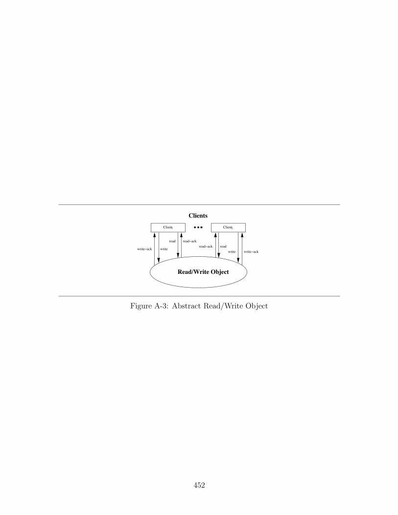
Clienti Clientj
Clients
Read/Write Object
write!ackwritereadread!ack
read!ackread
writewrite!ack
Figure A-3: Abstract Read/Write Object
452

Figure A-3 depicts the atomic object derived from the read/write variable type.In diagrams like Figure A-3, for clarity of presentation, instead of writing invoke(read)and the corresponding respond(read-ack), we write read and read-ack, as the directionof the arrows makes clear the action involved. We also omit the parameters to theinvocations and responses.
Notice that the canonical automaton is not a distributed algorithm; it assumescentralized state that all the nodes can access. It does, however, support concurrentread and write invocations on different ports. The automaton simply performs theoperations in some order. This is consistent with the usual notion that an atomicobject serializes all of its operations.
Also notice that the canonical automaton is asynchronous, meaning that, formally,it is a timed I/O automaton in which there can be arbitrary time passage betweenany two discrete events.
The canonical automaton is presented with no liveness conditions. Often (asin [70]), there is an additional failp action, for each port in Q, and a “tasks” specifi-cation requires that as long as no failp action occurs, each invocation on p eventuallyleads to a response.
A.3.3 Implementing Canonical Objects
We next define what it means for an environment to be well-formed:
Definition A.3.1. We say that a timed I/O automaton U is a well-formed environ-ment for an atomic object if:
1. Its outputs are exactly the invocations of the object, and its inputs are exactlythe responses of the object.
2. In every execution, for every port p, the automaton never performs two consec-utive invocations on port p without an intervening response on port p.
We then say that an automaton S implements the canonical (abstract) object, A,if:
1. S has the same input and output actions as A, the canonical object.
2. If U is a well-formed environment, then any trace of S × U is also a trace ofA×U . This implies that S preserves the well-formedness and safety guaranteesof A .
(Informally, a trace of an automaton is the sequence of input and output actionsoccurring in an execution, along with appropriate timing information as to when theinputs and outputs occur. The symbol × represents the composition of automata, asdefined in [70])
The most common way of showing that an algorithm implements an atomic objectis to show that in every execution there exists a total ordering of the operationswith certain properties. This ordering reflects the order in which the operations are
453
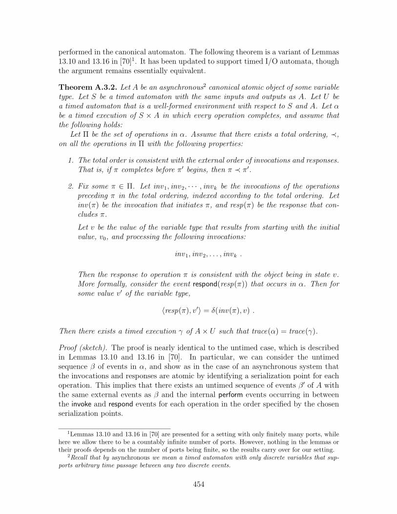
performed in the canonical automaton. The following theorem is a variant of Lemmas13.10 and 13.16 in [70]1. It has been updated to support timed I/O automata, thoughthe argument remains essentially equivalent.
Theorem A.3.2. Let A be an asynchronous2 canonical atomic object of some variabletype. Let S be a timed automaton with the same inputs and outputs as A. Let U bea timed automaton that is a well-formed environment with respect to S and A. Let αbe a timed execution of S × A in which every operation completes, and assume thatthe following holds:
Let Π be the set of operations in α. Assume that there exists a total ordering, ≺,on all the operations in Π with the following properties:
1. The total order is consistent with the external order of invocations and responses.That is, if π completes before π′ begins, then π ≺ π′.
2. Fix some π ∈ Π. Let inv 1, inv 2, · · · , invk be the invocations of the operationspreceding π in the total ordering, indexed according to the total ordering. Letinv(π) be the invocation that initiates π, and resp(π) be the response that con-cludes π.
Let v be the value of the variable type that results from starting with the initialvalue, v0, and processing the following invocations:
inv 1, inv 2, . . . , invk .
Then the response to operation π is consistent with the object being in state v.More formally, consider the event respond(resp(π)) that occurs in α. Then forsome value v′ of the variable type,
〈resp(π), v′〉 = δ(inv(π), v) .
Then there exists a timed execution γ of A× U such that trace(α) = trace(γ).
Proof (sketch). The proof is nearly identical to the untimed case, which is describedin Lemmas 13.10 and 13.16 in [70]. In particular, we can consider the untimedsequence β of events in α, and show as in the case of an asynchronous system thatthe invocations and responses are atomic by identifying a serialization point for eachoperation. This implies that there exists an untimed sequence of events β′ of A withthe same external events as β and the internal perform events occurring in betweenthe invoke and respond events for each operation in the order specified by the chosenserialization points.
1Lemmas 13.10 and 13.16 in [70] are presented for a setting with only finitely many ports, whilehere we allow there to be a countably infinite number of ports. However, nothing in the lemmas ortheir proofs depends on the number of ports being finite, so the results carry over for our setting.
2Recall that by asynchronous we mean a timed automaton with only discrete variables that sup-ports arbitrary time passage between any two discrete events.
454

Finally, we transform β′ into an execution of A by specifying the time at whicheach event occurs: each external event in β′ occurs at the identical time as its matchingevent in α; each internal event in β′ occurs at the earliest time that does not precededany event prior to it in β′. The result is an execution γ of A×U such that trace(α) =trace(γ).
Since U is an arbitrary environment, this implies that S implements A.Property 1 requires that the total ordering be consistent with the real-world order-
ing of operations. Consider the example of a read/write atomic object: this propertyrequires that if a write operation successfully completes and writes some value, val ,then a later read operation cannot return an earlier value.
Property 2 requires that the total ordering of operations be consistent with theactual responses sent during the execution, since the total ordering is supposed torepresent the order in which operations appear to happen. Consider again the exampleof a read/write atomic object: Property 2 guarantees that if, in the real execution,a read operation returns some value, val , then the closest preceding write operation(in the total order) must write that same value val .
The proof of Theorem A.3.2 is similar to that of Lemma 13.16 in [70]:
Proof (sketch). The proof involves choosing a serialization point for each operation:the earliest point after which the operation has begun and every operation precedingit in the total order has begun, where ties are ordered consistently with the total order.Property 1 ensures that the serialization point occurs before the operation completesand Property 2 ensures that the serialized execution has the same responses as thereal execution.
In the case of a read/write atomic object, it is necessary to determine only apartial ordering of the operations. The following theorem, then, is the analogue ofTheorem A.3.2, and is proved in [70], Lemmas 13.10 and Lemma 13.163:
Theorem A.3.3. Let A be a canonical atomic read/write object (i.e., an object of thevariable type presented in Figure A-1), and assume that S is an automaton with thesame inputs and outputs as A, and that U is any well-formed environment. For everyexecution α of S ◦ U in which every operation completes, assume that the followingholds:
Let Π be the set of operations in α. Assume that there exists a partial ordering,≺, on all the operations in Π with the following properties:
1. All write operations are totally ordered, and every read operation is ordered withrespect to all the writes.
2. The partial order is consistent with the external order of invocations and re-sponses, that is, there do not exist read or write operations π1 and π2 such thatπ1 completes before π2 starts, yet π2 ≺ π1.
3In [70], a fourth property is included, assuming that each operation is preceded by only finitelymany other operation. This is unnecessary, as it is implied by Property 2.
455

3. Every read operation that is ordered after any writes returns the value of thelast write preceding it in the partial order; any read operation ordered before allwrites returns v0.
Then traces(S ◦ U) ⊆ traces(A ◦ U).
Again, since U is an arbitrary environment, this implies that S implements A.
456
Index
♦A-C, 172accurate, 171advised to be active, 191advised to be passive, 191advises i to be active, 191advises i to be passive, 191algorithm, 168an epoch, 284anonymous, 168associated, 162, 170asynchronous, 447
bad round, 292basic system, 199beginning of basic round r, 279beginning of virtual round r, 279begins, 282broadcast complete, 316broadcast incomplete, 316broadcast ports, 162
calculate-last state, 318CDB, 198client processes, 215clients, 43, 48cm-sampling, 360collision detector, 171collision detector rule, 170compatible, 447complete, 171, 206completes, 282configuration, 118conservative, 195contends for CM in round r, 190contends in round r, 190contention manager, 172correct, 47, 50, 165
departure time, 46, 49, 50
detects a collision in round r, 188down, 283dynamic, 30Dynamic Virtual Node Layer, 49Dynamic Virtual Object Layer, 46
emulator system, 267end of basic round r, 279end of virtual round r, 279eventual collision freedom, 195eventual collision freedom with good ad-
vice, 196eventual `-regionally fair, 194eventually (a, b)-contention fair, 193eventually accurate, 172eventually fair, 192eventually non-interfering, 192exec(r1, r2, i)v, 318execs(r1, r2)v, 319executes a reset, 282external, 446
failed in round r, 186fails in round r, 186faulty, 165focal point center, 30focal point region, 30
γi, 353general system, 182good round, 292green round, 292
IB, 198infinite execution, 186inner region, 33input enabled, 446inside, 32integrity, 187
457

interfere(`, r, S), 192internal, 446internally progressive, 447
joins, 282
last agreement phase, 282locally controlled, 446locally Zeno, 447`-restricted contention, 194
near(`, [r1, r2], S), 191near(`, r, S), 191non-conflicting, 206
parameters for a general system, 162partB, 199participates, 282payload, 67, 93populated throughout, 46, 49process, 164progressive, 447
[r1, r2]-execution, 317[r1, r2]-execution fragment, 316racc, 189radius, 30R′B, 198RB, 198recoverable, 165recovers in round r, 186red round, 292Remap(p, i), 170remapped, 170remapped process, 170replicas, 219reset identifier, 102responsible, 422restricting, 448round r, 173round r advice event, 184round r broadcast event, 183round r fail event, 184round r next-round event, 184round r process event, 184round r receive event, 183
round r recover event, 184round r2 ballot, 306round r2 proposer, 306RndLengthB, 198r-round execution, 185
safe, 94scheduled, 281self-delivery, 187size, 207static, 30, 45, 49Static Virtual Node Layer, 49Static Virtual Object Layer, 46
time-passage enabled, 446
unrecoverable, 165unscheduled, 281up, 283updown, 285updown(v), 286
virtual GeoCast, 50virtual infrastructure system, 203, 208Virtual Node Layer, 43, 48virtual nodes, 48Virtual Object Emulator, 58Virtual Object Layer, 43virtual objects, 43virtual processes, 215Virtual round r, 278VNE-Client, 84VNE-Server, 84VOE-Client, 58VOE-Server, 58
well inside, 32
458