virtual device context (vdc) design and...
TRANSCRIPT
BRKDCT-2121
Virtual Device Context (VDC) Design and Implementation Considerations with Nexus 7000 Ron Fuller– CCIE #5851 (R&S/Storage) Technical Marketing Engineer, Nexus 7000 [email protected]
Follow us on Twitter for real time updates of the event:
@ciscoliveeurope, #CLEUR
© 2012 Cisco and/or its affiliates. All rights reserved. Cisco Public Presentation_ID 2
Housekeeping
We value your feedback- don't forget to complete your online session evaluations after each session & the Overall Conference Evaluation which will be available online from Thursday
Visit the World of Solutions and Meet the Engineer
Visit the Cisco Store to purchase your recommended readings
Please switch off your mobile phones
After the event don‘t forget to visit Cisco Live Virtual: www.ciscolivevirtual.com
Follow us on Twitter for real time updates of the event: @ciscoliveeurope, #CLEUR

© 2012 Cisco and/or its affiliates. All rights reserved. Cisco Public BRKDCT-2121 3
Course Objective
What you will learn…..
VDC Configuration Guidelines
Common VDC Use Cases
How to use VDCs with Advanced Applications

© 2012 Cisco and/or its affiliates. All rights reserved. Cisco Public BRKDCT-2121 4
Agenda
Virtual Device Context (VDC) Overview
- What are VDCs?
- VDC Types
- Resource Allocation
- Interface Allocation
- VDC Operation and Management
- Leading practices
Consolidation with VDCs
Segmentation with VDCs
Advanced Applications and VDCs
Q&A

Virtual Device Context (VDC) Overview
© 2012 Cisco and/or its affiliates. All rights reserved. Cisco Public BRKDCT-2121 6
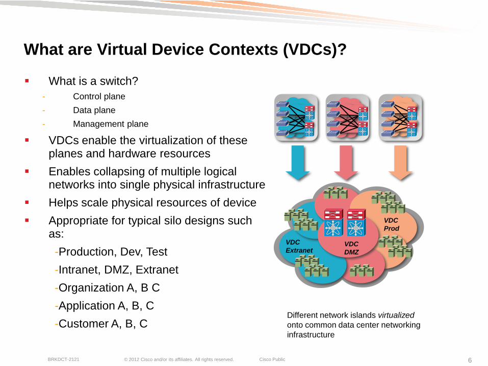
What are Virtual Device Contexts (VDCs)?
What is a switch?
- Control plane
- Data plane
- Management plane
VDCs enable the virtualization of these planes and hardware resources
Enables collapsing of multiple logical networks into single physical infrastructure
Helps scale physical resources of device
Appropriate for typical silo designs such as:
-Production, Dev, Test
-Intranet, DMZ, Extranet
-Organization A, B C
-Application A, B, C
-Customer A, B, C
Different network islands virtualized
onto common data center networking
infrastructure
VDC
Extranet
VDC
Prod
VDC
DMZ

© 2012 Cisco and/or its affiliates. All rights reserved. Cisco Public BRKDCT-2121 7
Virtual Device Contexts (VDCs)
VDC—Virtual Device Context
- Flexible separation/distribution of Software Components
- Flexible separation/distribution of Hardware Resources
- Securely delineated Administrative Contexts
VDCs are not…
- The ability to run different OS levels on the same box at the same time
- based on a hypervisor model; there is a single ‗infrastructure‘ layer that handles h/w programming…
Infrastructure
Layer-2 Protocols Layer-3 Protocols
VLAN mgr
STP
OSPF
BGP
EIGRP
GLBP
HSRP
VRRP
UDLD
CDP
802.1X IGMP sn.
LACP PIM CTS SNMP
RIB RIB
Protocol Stack (IPv4 / IPv6 / L2)
Layer-2 Protocols Layer-3 Protocols
VLAN mgr
STP
OSPF
BGP
EIGRP
GLBP
HSRP
VRRP
UDLD
CDP
802.1X IGMP sn.
LACP PIM CTS SNMP
RIB RIB
Protocol Stack (IPv4 / IPv6 / L2)
Kernel
VDC A
VDC B
VDC A VDC B
VDC n

© 2012 Cisco and/or its affiliates. All rights reserved. Cisco Public BRKDCT-2121 8
Nexus
7000
Virtualization Hierarchy Where are VDCs reside in the ―Big Picture‖
VDC1 VLAN VLAN VLAN VRF VRF VRF
VLAN VLAN VLAN VRF VRF VRF
VDC2 VLAN VLAN VLAN VRF VRF VRF
VLAN VLAN VLAN VRF VRF VRF
VDC3 VLAN VLAN VLAN VRF VRF VRF
VLAN VLAN VLAN VRF VRF VRF
VDC4 VLAN VLAN VLAN VRF VRF VRF
VLAN VLAN VLAN VRF VRF VRF
© 2012 Cisco and/or its affiliates. All rights reserved. Cisco Public BRKDCT-2121 9
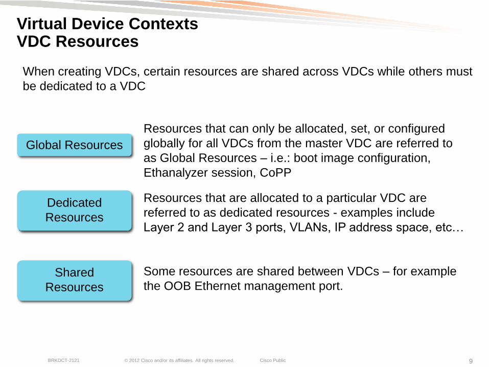
Virtual Device Contexts VDC Resources
Resources that can only be allocated, set, or configured
globally for all VDCs from the master VDC are referred to
as Global Resources – i.e.: boot image configuration,
Ethanalyzer session, CoPP
Resources that are allocated to a particular VDC are
referred to as dedicated resources - examples include
Layer 2 and Layer 3 ports, VLANs, IP address space, etc…
Some resources are shared between VDCs – for example
the OOB Ethernet management port.
When creating VDCs, certain resources are shared across VDCs while others must
be dedicated to a VDC
Global Resources
Dedicated
Resources
Shared
Resources
© 2012 Cisco and/or its affiliates. All rights reserved. Cisco Public BRKDCT-2121 10
Base
Enterprise Advanced Enhanced L2 SAN
Enterprise
MPLS XL Transport
Services
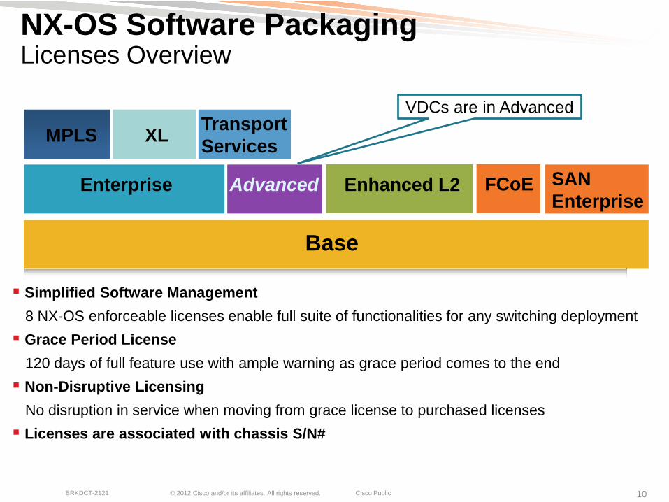
NX-OS Software Packaging Licenses Overview
Simplified Software Management
8 NX-OS enforceable licenses enable full suite of functionalities for any switching deployment
Grace Period License
120 days of full feature use with ample warning as grace period comes to the end
Non-Disruptive Licensing
No disruption in service when moving from grace license to purchased licenses
Licenses are associated with chassis S/N#
FCoE
VDCs are in Advanced
© 2012 Cisco and/or its affiliates. All rights reserved. Cisco Public BRKDCT-2121 11
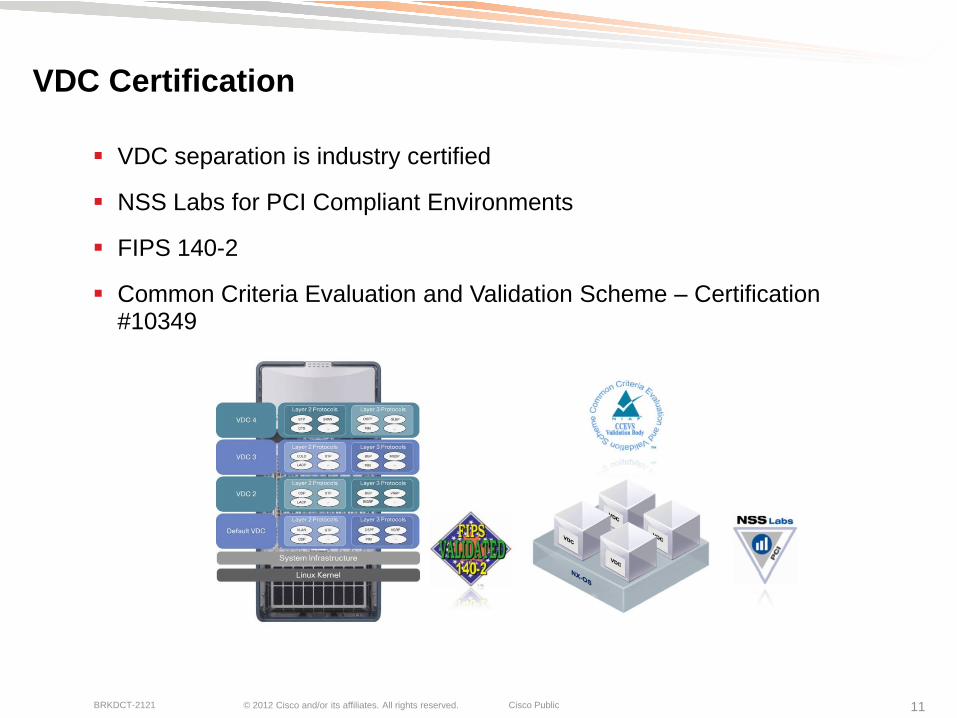
VDC Certification
VDC separation is industry certified
NSS Labs for PCI Compliant Environments
FIPS 140-2
Common Criteria Evaluation and Validation Scheme – Certification #10349
© 2012 Cisco and/or its affiliates. All rights reserved. Cisco Public BRKDCT-2121 12
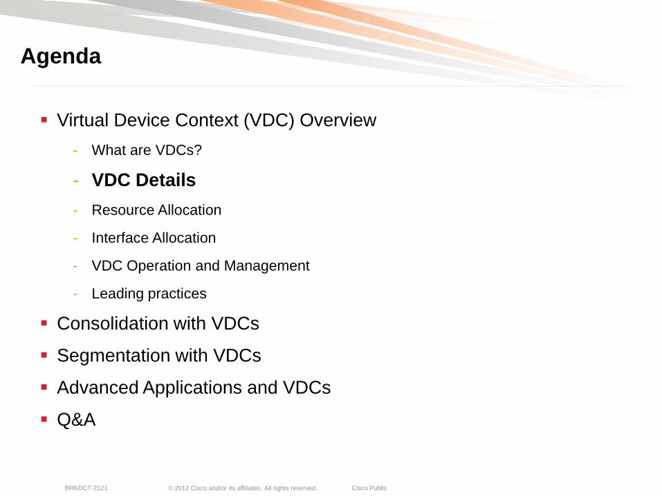
Virtual Device Context (VDC) Overview
- What are VDCs?
- VDC Details
- Resource Allocation
- Interface Allocation
- VDC Operation and Management
- Leading practices
Consolidation with VDCs
Segmentation with VDCs
Advanced Applications and VDCs
Q&A
Agenda
© 2012 Cisco and/or its affiliates. All rights reserved. Cisco Public BRKDCT-2121 13
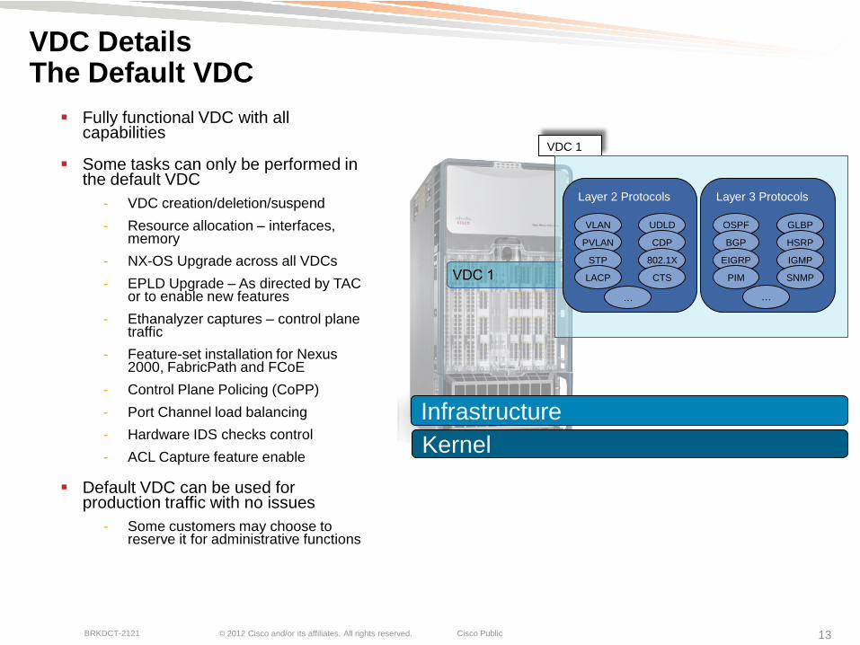
VDC Details The Default VDC
Fully functional VDC with all capabilities
Some tasks can only be performed in the default VDC
- VDC creation/deletion/suspend
- Resource allocation – interfaces, memory
- NX-OS Upgrade across all VDCs
- EPLD Upgrade – As directed by TAC or to enable new features
- Ethanalyzer captures – control plane traffic
- Feature-set installation for Nexus 2000, FabricPath and FCoE
- Control Plane Policing (CoPP)
- Port Channel load balancing
- Hardware IDS checks control
- ACL Capture feature enable
Default VDC can be used for production traffic with no issues
- Some customers may choose to reserve it for administrative functions
Infrastructure
Kernel
VDC 1
VDC 1
Layer 3 Protocols
GLBP GLBP
Layer 2 Protocols
VLAN
PVLAN
OSPF
BGP
EIGRP
HSRP
IGMP
UDLD
CDP
802.1X STP
LACP PIM CTS SNMP
… …

© 2012 Cisco and/or its affiliates. All rights reserved. Cisco Public BRKDCT-2121 14
VDC Details Non-Default VDC
Fully functional VDC with all capabilities
Changes in non-default VDC only affect that particular VDC
Independent processes started for each protocol in each VDC
Discrete configuration file per VDC
Discrete checkpoints per VDC
Discrete RBAC, TACACS, SNMP, etc.
Infrastructure
Kernel
VDC 2
VDC 3
VDC 4
Layer 3 Protocols
OSPF
BGP
EIGRP
GLBP
HSRP
IGMP
PIM SNMP
…
VDC 2, 3 or 4
Layer 2 Protocols
VLAN
PVLAN
UDLD
CDP
802.1X STP
LACP CTS
…

© 2012 Cisco and/or its affiliates. All rights reserved. Cisco Public BRKDCT-2121 15
VDC Types ―Module-Type‖ Modes
In release 5.1, ―module-type‖ parameter defines the behavior for each VDC
Different I/O module types can be specified:
- m1 – specifies VDC can contain M1 modules
- m1-xl – specifies VDC can contain M1-XL modules
- m2-xl - specifies VDC can contain M2-XL modules
- f1 – specifies VDC can contain F1 modules
- f2 – specifies VDC can contain F2 modules
limit-resource module-type f1 m1 m1-xl m2-xl (default) – Allows mix of M1, M1-XL, M2 and F1 modules in the VDC
M1-XL
Only VDC
F1 Only VDC
M1-F1 Mixed VDC
© 2012 Cisco and/or its affiliates. All rights reserved. Cisco Public BRKDCT-2121 16
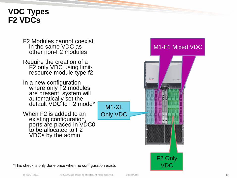
VDC Types F2 VDCs
F2 Modules cannot coexist in the same VDC as other non-F2 modules
Require the creation of a F2 only VDC using limit-resource module-type f2
In a new configuration where only F2 modules are present system will automatically set the default VDC to F2 mode*
When F2 is added to an existing configuration, ports are placed in VDC0 to be allocated to F2 VDCs by the admin
M1-XL
Only VDC
F2 Only
VDC
M1-F1 Mixed VDC
*This check is only done once when no configuration exists
© 2012 Cisco and/or its affiliates. All rights reserved. Cisco Public BRKDCT-2121 17
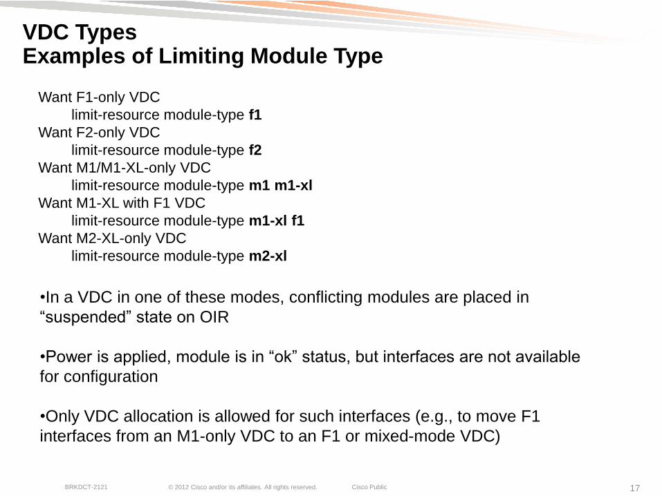
VDC Types Examples of Limiting Module Type
•In a VDC in one of these modes, conflicting modules are placed in
―suspended‖ state on OIR
•Power is applied, module is in ―ok‖ status, but interfaces are not available
for configuration
•Only VDC allocation is allowed for such interfaces (e.g., to move F1
interfaces from an M1-only VDC to an F1 or mixed-mode VDC)
Want F1-only VDC
limit-resource module-type f1
Want F2-only VDC
limit-resource module-type f2
Want M1/M1-XL-only VDC
limit-resource module-type m1 m1-xl
Want M1-XL with F1 VDC
limit-resource module-type m1-xl f1
Want M2-XL-only VDC
limit-resource module-type m2-xl

© 2012 Cisco and/or its affiliates. All rights reserved. Cisco Public BRKDCT-2121 18
VDC Types Storage VDC
Enables separation of job functions for LAN and SAN Admin
Creates a ―virtual‖ MDS within the Nexus 7000
- Participates as a full Fibre Channel Forwarder (FCF) in the network
- Zoning, FC alias, fcdomains, IVR, Fabric Binding, etc
FCoE Target Support
FCoE ISLs to other switches – Nexus 7000, 5000, MDS
Only one storage VDC per chassis
- Does not require Advanced License (VDCs)
- Does count towards total VDC count – 4 per Nexus 7000
Fibre
Channel
Storage
VDC
Ethernet
VDC
© 2012 Cisco and/or its affiliates. All rights reserved. Cisco Public BRKDCT-2121 19
Virtual Device Context (VDC) Overview
- What are VDCs?
- VDC types
- Resource Allocation
- Interface Allocation
- VDC Operation and Management
- Leading practices
Consolidation with VDCs
Segmentation with VDCs
Advanced Applications and VDCs
Q&A
Agenda

© 2012 Cisco and/or its affiliates. All rights reserved. Cisco Public BRKDCT-2121 20
Resource Allocation
Ability to allocate resources ―as needed‖
Different VDCs may have different requirements
Production vs. Test/Dev
Multi-tenancy into shared infrastructure

© 2012 Cisco and/or its affiliates. All rights reserved. Cisco Public BRKDCT-2121 21
Resource Allocation Dedicated Resources that can be Allocated
Certain resources can be allocated and limited to a given VDC:
m4route-mem Set ipv4 route memory limits
m6route-mem Set ipv6 route memory limits
module-type Controls which type of modules are allowed in this vdc
monitor-session Monitor local/erspan-source session
monitor-session-erspan-dst Monitor erspan destination session
port-channel Set port-channel limits
u4route-mem Set ipv4 route memory limits
u6route-mem Set ipv6 route memory limits
vlan Set VLAN limits
vrf Set vrf resource limits
How much RAM do I allocate for my routing tables?
• Routing table memory limits are in MB. For an idea of MB to routes you can use the command ―show
routing ipv4|ipv6 memory estimate routes <1000-1000000> next-hops <1-16>‖
• u4route-mem and u6route-mem limits are only applied after a switchover or reload – they are not hot
updates.
© 2012 Cisco and/or its affiliates. All rights reserved. Cisco Public BRKDCT-2121 22
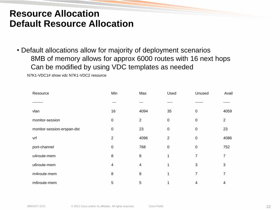
Resource Allocation Default Resource Allocation
N7K1-VDC1# show vdc N7K1-VDC2 resource
Resource Min Max Used Unused Avail
-------- --- --- ---- ------ -----
vlan 16 4094 35 0 4059
monitor-session 0 2 0 0 2
monitor-session-erspan-dst 0 23 0 0 23
vrf 2 4096 2 0 4086
port-channel 0 768 0 0 752
u4route-mem 8 8 1 7 7
u6route-mem 4 4 1 3 3
m4route-mem 8 8 1 7 7
m6route-mem 5 5 1 4 4
• Default allocations allow for majority of deployment scenarios
8MB of memory allows for approx 6000 routes with 16 next hops
Can be modified by using VDC templates as needed
© 2012 Cisco and/or its affiliates. All rights reserved. Cisco Public BRKDCT-2121 23
Virtual Device Context (VDC) Overview
- What are VDCs?
- VDC Types
- Resource Allocation
- Interface Allocation
- VDC Operation and Management
- Leading practices
Consolidation with VDCs
Segmentation with VDCs
Advanced Applications and VDCs
Q&A
Agenda

© 2012 Cisco and/or its affiliates. All rights reserved. Cisco Public BRKDCT-2121 24
Interface Allocation Interface Allocation N7K-M206QF-23L
6 port
40GE
module
VDC
A
VDC
B
VDC
C
VDC
D
Ports are assigned on a per VDC basis
and cannot be shared across VDCs
Once a port has been assigned to a VDC,
all subsequent configuration is done from
within that VDC
Each port on a N7K-M206QF-23L has its
own ASIC.
© 2012 Cisco and/or its affiliates. All rights reserved. Cisco Public BRKDCT-2121 25
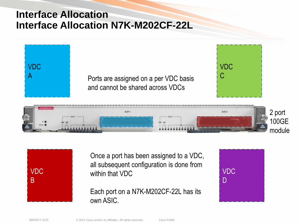
Interface Allocation Interface Allocation N7K-M202CF-22L
2 port
100GE
module
VDC
A
VDC
B
VDC
C
VDC
D
Ports are assigned on a per VDC basis
and cannot be shared across VDCs
Once a port has been assigned to a VDC,
all subsequent configuration is done from
within that VDC
Each port on a N7K-M202CF-22L has its
own ASIC.
© 2012 Cisco and/or its affiliates. All rights reserved. Cisco Public BRKDCT-2121 26
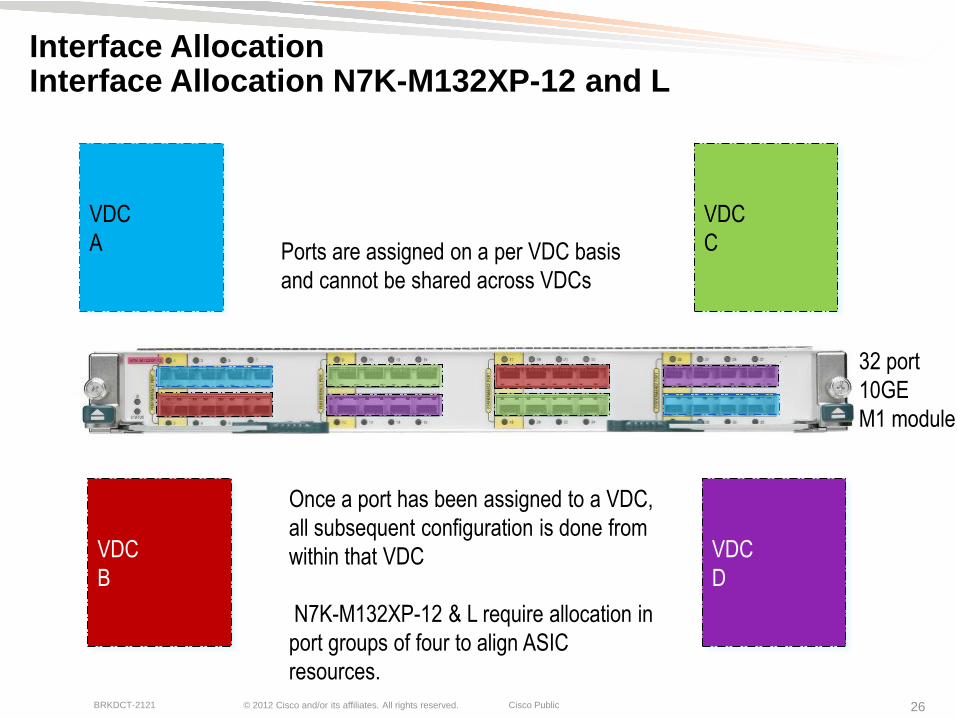
Interface Allocation Interface Allocation N7K-M132XP-12 and L
32 port
10GE
M1 module
VDC
A
VDC
B
VDC
C
VDC
D
Ports are assigned on a per VDC basis
and cannot be shared across VDCs
Once a port has been assigned to a VDC,
all subsequent configuration is done from
within that VDC
N7K-M132XP-12 & L require allocation in
port groups of four to align ASIC
resources.

© 2012 Cisco and/or its affiliates. All rights reserved. Cisco Public BRKDCT-2121 27
Interface Allocation Interface Allocation N7K-F132XP-15
32 port
10GE
F1 module
VDC
A
VDC
B
VDC
C
VDC
D
Ports are assigned on a per VDC basis
and cannot be shared across VDCs unless
using FCoE
Once a port has been assigned to a VDC,
all subsequent configuration is done from
within that VDC
N7K-F132XP-15 Requires allocation in
port groups of two to align ASIC
resources.

© 2012 Cisco and/or its affiliates. All rights reserved. Cisco Public BRKDCT-2121 28
Interface Allocation Interface Allocation N7K-F248XP-25
48 port
10GE
F2 module
VDC
A
VDC
B
VDC
C
VDC
D
Ports are assigned on a per VDC basis
and cannot be shared across VDCs
Once a port has been assigned to a VDC,
all subsequent configuration is done from
within that VDC
N7K-F248XP-25 Requires allocation in
port groups of four to align ASIC
resources.

© 2012 Cisco and/or its affiliates. All rights reserved. Cisco Public BRKDCT-2121 29
Interface Allocation Interface Allocation N7K-M108X2-12L
8 port
10GE
module
VDC
A
VDC
B
VDC
C
VDC
D
Ports are assigned on a per VDC basis
and cannot be shared across VDCs
Once a port has been assigned to a VDC,
all subsequent configuration is done from
within that VDC
Each port on a N7K-M108X2-12L has its
own ASIC.

© 2012 Cisco and/or its affiliates. All rights reserved. Cisco Public BRKDCT-2121 30
Interface Allocation Interface Allocation 10/100/1000 Modules
48-port
10/100/1000
VDC
A
VDC
B
VDC
C
VDC
D
Ports are assigned on a per VDC
basis and cannot be shared across
VDCs Once a port has been assigned to
a VDC, all subsequent
configuration is done from within
that VDC
*Note – The M1 48 port line cards
have 4 port groups of 12 ports.
Recommendation is to have all
members of a port group in the same
VDC

© 2012 Cisco and/or its affiliates. All rights reserved. Cisco Public BRKDCT-2121 31
Interface Allocation VDC and Interface Allocation
Ports are allocated in VDC config mode
N7K1-VDC1# confi t
Enter configuration commands, one per line. End with CNTL/Z.
N7K1-VDC1(config)# vdc N7K1-VDC2
N7K1-VDC1(config-vdc)# allocate interface e8/1-12
Moving ports will cause all config associated to them in source vdc to be removed. Are
you sure you want to move the ports (y/n)? [yes] yes
N7K1-VDC1(config-vdc)# show vdc membership
vdc_id: 4 vdc_name: N7K1-VDC2 interfaces:
Ethernet8/1 Ethernet8/2 Ethernet8/3
Ethernet8/4 Ethernet8/5 Ethernet8/6
Ethernet8/7 Ethernet8/8 Ethernet8/9
Ethernet8/10 Ethernet8/11 Ethernet8/12
N7K1-VDC1(config-vdc)# allocate interface ethernet 4/1
Entire port-group is not present in the command. Missing ports will be included
automatically
Moving ports will cause all config associated to them in source vdc to be removed. Are
you sure you want to move the ports (y/n)? [yes]
Note that FEX ports only exist in the VDC where their
parent interfaces reside
Disruptive
warning!
Ports being
allocated
Easier allocation
in NX-OS 5.2

© 2012 Cisco and/or its affiliates. All rights reserved. Cisco Public BRKDCT-2121 32
Interface Allocation Shared Interfaces
Exception to the rule allowing an interface to exist in only one VDC
Splits traffic based on Ethertype
Ethernet VDC ―owns‖ interface
Storage VDC sees the interface as well
CNA
Storage
VDC Ethernet
VDC
FCoE Initialization Protocol (FIP)
Ethertype 0x8914 and FCoE
0x8906 only are directed to the
storage VDC. All other Ethertypes
are directed toward the Ethernet
VDC
© 2012 Cisco and/or its affiliates. All rights reserved. Cisco Public BRKDCT-2121 33
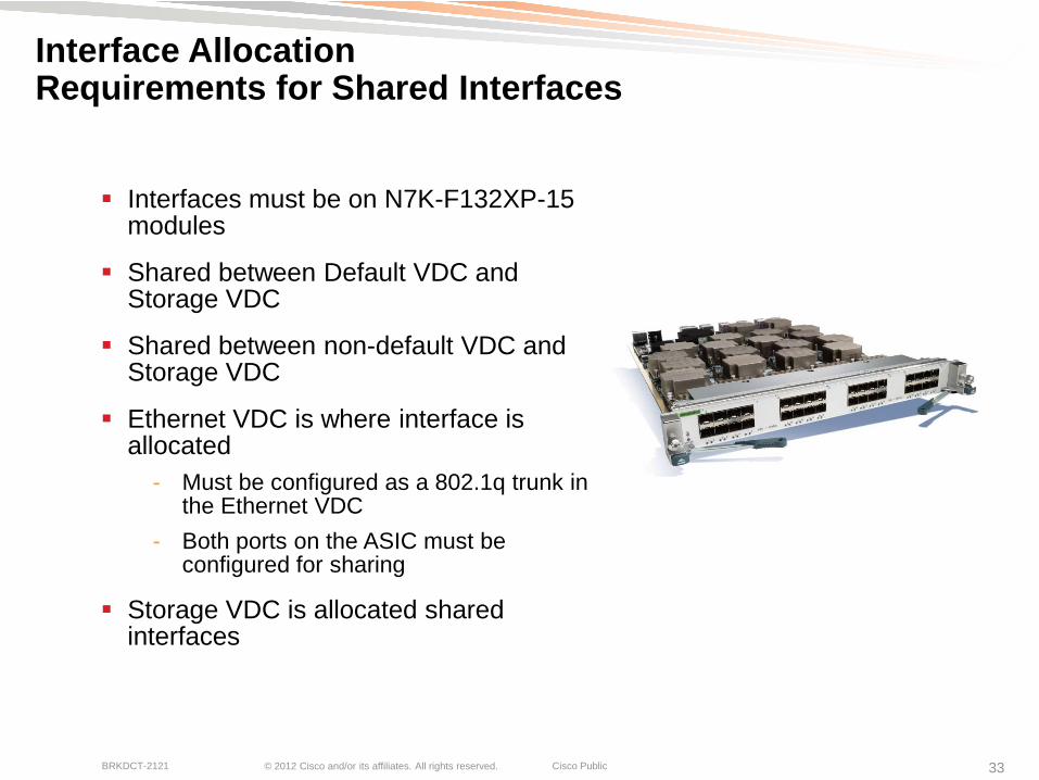
Interface Allocation Requirements for Shared Interfaces
Interfaces must be on N7K-F132XP-15 modules
Shared between Default VDC and Storage VDC
Shared between non-default VDC and Storage VDC
Ethernet VDC is where interface is allocated
- Must be configured as a 802.1q trunk in the Ethernet VDC
- Both ports on the ASIC must be configured for sharing
Storage VDC is allocated shared interfaces

© 2012 Cisco and/or its affiliates. All rights reserved. Cisco Public BRKDCT-2121 34
Interface Allocation Configuring Shared Interfaces
Interfaces already allocated to N7K1-VDC1
N7K1-VDC1# config
N7K1-VDC1(config)# vdc fcoe
N7K1-VDC1(config-vdc)# allocate fcoe-vlan-range 2000-2100 from vdc N7K1-VDC1
N7K1-VDC1(config-vdc)# allocate shared interface e3/25-26
Ports that share the port group of the interfaces you have specified will be affected as well. Continue (y/n)? [yes] yes
N7K1-VDC1(config-vdc)# end
N7K1-VDC1# switchto vdc fcoe
FCoE# show int brief
Eth3/25 1 eth trunk down Administratively down auto(D) --
Eth3/26 1 eth trunk down Administratively down auto(D) --
FCoE#
Allocate VLANs and Interfaces
Interfaces can be controlled per VDC

© 2012 Cisco and/or its affiliates. All rights reserved. Cisco Public BRKDCT-2121 35
Communicating Between VDCs
Must use front panel port to communicate between VDCs
- No soft cross-connect or backplane inter-VDC communications
Storage shared ports can communicate with each other *within* their respective VDC
Front panel ports align security models, ensure QoS, ACL, Netflow, etc. resources
No restrictions on L2/L3 or linecard models
When using vPC or vPC+ between VDCs, ensure domain IDs are unique
VDC2
VDC3
© 2012 Cisco and/or its affiliates. All rights reserved. Cisco Public BRKDCT-2121 36
VD
C
30
VD
C
20
VD
C
20
VD
C
20
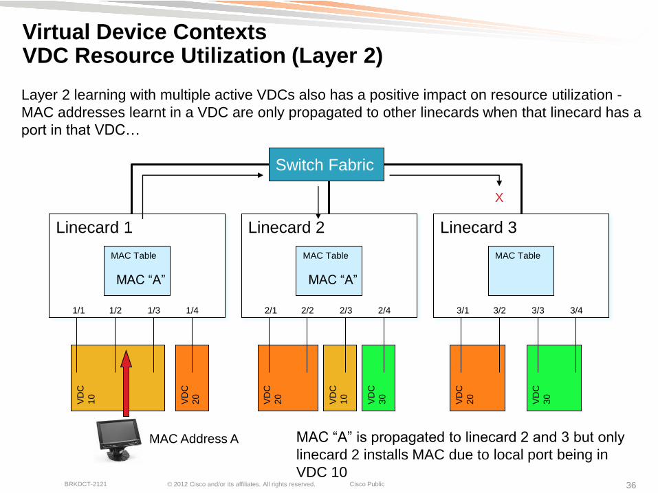
Virtual Device Contexts VDC Resource Utilization (Layer 2)
Layer 2 learning with multiple active VDCs also has a positive impact on resource utilization -
MAC addresses learnt in a VDC are only propagated to other linecards when that linecard has a
port in that VDC…
Switch Fabric
Linecard 1 Linecard 2 Linecard 3
MAC Table MAC Table MAC Table
VD
C
10
VD
C
10
VD
C
30
1/1 1/2 1/3 1/4 2/1 2/2 2/3 2/4 3/1 3/2 3/3 3/4
MAC Address A
MAC ―A‖ MAC ―A‖
X
MAC ―A‖ is propagated to linecard 2 and 3 but only
linecard 2 installs MAC due to local port being in
VDC 10

© 2012 Cisco and/or its affiliates. All rights reserved. Cisco Public BRKDCT-2121 37
Virtual Device Contexts VDC Resource Utilization (Layer 3)
Linecard 1 Linecard 2 Linecard 3 Linecard 4 Linecard 5 Linecard 6 Linecard 7 Linecard 8
64K 64K 64K 64K 64K 64K 64K 64K
128K 128K 128K 128K 128K 128K 128K 128K
FIB
TCAM
FIB
TCAM
FIB
TCAM
FIB
TCAM
FIB
TCAM
FIB
TCAM
FIB
TCAM
FIB
TCAM
ACL
TCAM
ACL
TCAM
ACL
TCAM
ACL
TCAM
ACL
TCAM
ACL
TCAM
ACL
TCAM
ACL
TCAM
When only the default VDC is active, the FIB and ACL TCAM on each linecard is
primed with forwarding prefixes and policies associated with that default VDC as
shown below…

© 2012 Cisco and/or its affiliates. All rights reserved. Cisco Public BRKDCT-2121 38
Virtual Device Contexts VDC Resource Utilization (Layer 3)
Linecard 1 Linecard 2 Linecard 3 Linecard 4 Linecard 5 Linecard 6 Linecard 7 Linecard 8
64K 64K 64K 64K 64K 64K 64K 64K
128K 128K 128K 128K 128K 128K 128K 128K
FIB
TCAM
FIB
TCAM
FIB
TCAM FIB
TCAM FIB
TCAM
FIB
TCAM
FIB
TCAM FIB
TCAM
ACL
TCAM
ACL
TCAM ACL
TCAM
ACL
TCAM
ACL
TCAM ACL
TCAM ACL
TCAM
ACL
TCAM
VDC 10 VDC 20 VDC 30
FIB and ACL TCAM
resources are more
effectively utilized…

© 2012 Cisco and/or its affiliates. All rights reserved. Cisco Public BRKDCT-2121 39
Control Plane Policing and VDCs
CoPP works per forwarding engine, as such it is VDC "agnostic―
If ports for the same forwarding engine are shared between VDCs and CoPP thresholds are violated, CoPP will start dropping matching traffic for all ports of this forwarding engine,
This behavior might break the separation of VDCs
If ports of one forwarding engine belong to different VDCs you can limit this effect:
The ACL e.g. for ARP and ICMP are use "match protocol" but didn't specify networks.
If VDCs using different IP ranges, it is possible to define different CoPP policies based on IP ACLs per protocol

© 2012 Cisco and/or its affiliates. All rights reserved. Cisco Public BRKDCT-2121 40
Virtual Device Context (VDC) Overview
- What are VDCs?
- VDC Types
- Resource Allocation
- Interface Allocation
- VDC Operation and Management
- Leading practices
Consolidation with VDCs
Segmentation with VDCs
Advanced Applications and VDCs
Q&A
Agenda

© 2012 Cisco and/or its affiliates. All rights reserved. Cisco Public BRKDCT-2121 41
VDC Types VDC Creation - Ethernet
N7K1-VDC1# conf t
N7K1-VDC1(config)# vdc N7K1-VDC4
Note: Creating VDC, one moment please ...
N7K1-VDC1(config-vdc)# show vdc
vdc_id vdc_name state mac type lc
------ -------- ----- ---------- --------- ------
1 N7K1-VDC1 active 00:26:51:c7:34:41 Ethernet m1 f1 m1xl
2 N7K1-VDC2 active 00:26:51:c7:34:42 Ethernet m1 f1 m1xl
3 N7K1-VDC3 active 00:26:51:c7:34:43 Ethernet m1 f1 m1xl
4 N7K1-VDC4 active 00:26:51:c7:34:44 Ethernet m1 f1 m1xl
N7K1-VDC1(config-vdc)# show vdc N7K1-VDC4 detail
vdc id: 4
vdc name: N7K1-VDC4
vdc state: active
vdc mac address: 00:26:51:c7:34:44
vdc ha policy: RESTART
vdc dual-sup ha policy: SWITCHOVER
vdc boot Order: 1
vdc create time: Mon May 16 00:12:38 2011
vdc reload count: 0
vdc restart count: 0
vdc type: Ethernet
vdc supported linecards: m1 f1 m1xl
Name of New VDC
VDC Details

© 2012 Cisco and/or its affiliates. All rights reserved. Cisco Public BRKDCT-2121 42
VDC Types VDC Creation – Ethernet – F2 Module
N7K1-VDC1# conf t
N7K1-VDC1(config)# vdc N7K1-VDC4 limit-resource module-type f2
Note: Creating VDC, one moment please ...
N7K1-VDC1(config-vdc)# show vdc
vdc_id vdc_name state mac type lc
------ -------- ----- ---------- --------- ------
1 N7K1-VDC1 active 00:26:51:c7:34:41 Ethernet m1 f1 m1xl
2 N7K1-VDC2 active 00:26:51:c7:34:42 Ethernet m1 f1 m1xl
3 N7K1-VDC3 active 00:26:51:c7:34:43 Ethernet m1 f1 m1xl
4 N7K1-VDC4 active 00:26:51:c7:34:44 Ethernet f2
N7K1-VDC1(config-vdc)# show vdc N7K1-VDC4 detail
vdc id: 4
vdc name: N7K1-VDC4
vdc state: active
vdc mac address: 00:26:51:c7:34:44
vdc ha policy: RESTART
vdc dual-sup ha policy: SWITCHOVER
vdc boot Order: 1
vdc create time: Mon May 16 00:12:38 2011
vdc reload count: 0
vdc restart count: 0
vdc type: Ethernet
vdc supported linecards: f2
Limiting Resources
VDC Details

© 2012 Cisco and/or its affiliates. All rights reserved. Cisco Public BRKDCT-2121 43
VDC Types VDC Creation - Storage
N7K1-VDC1(config)# vdc FCoE type storage
Note: Creating VDC, one moment please ...
N7K1-VDC1(config-vdc)# show vdc
vdc_id vdc_name state mac type lc
------ -------- ----- ---------- --------- ------
1 N7K1-VDC1 active 00:26:51:c7:34:41 Ethernet m1 f1 m1xl
2 N7K1-VDC2 active 00:26:51:c7:34:42 Ethernet m1 f1 m1xl
3 N7K1-VDC3 active 00:26:51:c7:34:43 Ethernet m1 f1 m1xl
4 FCoE active 00:26:51:c7:34:44 Storage f1
N7K1-VDC1(config-vdc)# show vdc FCoE detail
vdc id: 4
vdc name: FCoE
vdc state: active
vdc mac address: 00:26:51:c7:34:44
vdc ha policy: RESTART
vdc dual-sup ha policy: SWITCHOVER
vdc boot Order: 1
vdc create time: Mon May 16 00:28:33 2011
vdc reload count: 0
vdc restart count: 0
vdc type: Storage
vdc supported linecards: f1
Name of VDC and type Storage
VDC Details

© 2012 Cisco and/or its affiliates. All rights reserved. Cisco Public BRKDCT-2121 44
Navigating Between VDCs
From the default VDC, use the switchto vdc <name> command
N7K1-VDC1# switchto vdc N7K1-VDC2
N7K1-VDC2#
To return to the default VDC use the switchback
N7K1-VDC2# switchback
N7K1-VDC1#
Tip – Use the cli alias command
cli alias name agg1 switchto vdc N7K1-VDC2
cli alias name agg2 switchto vdc N7K1-VDC3
cli alias name fcoe switchto vdc FCOE
© 2012 Cisco and/or its affiliates. All rights reserved. Cisco Public BRKDCT-2121 45
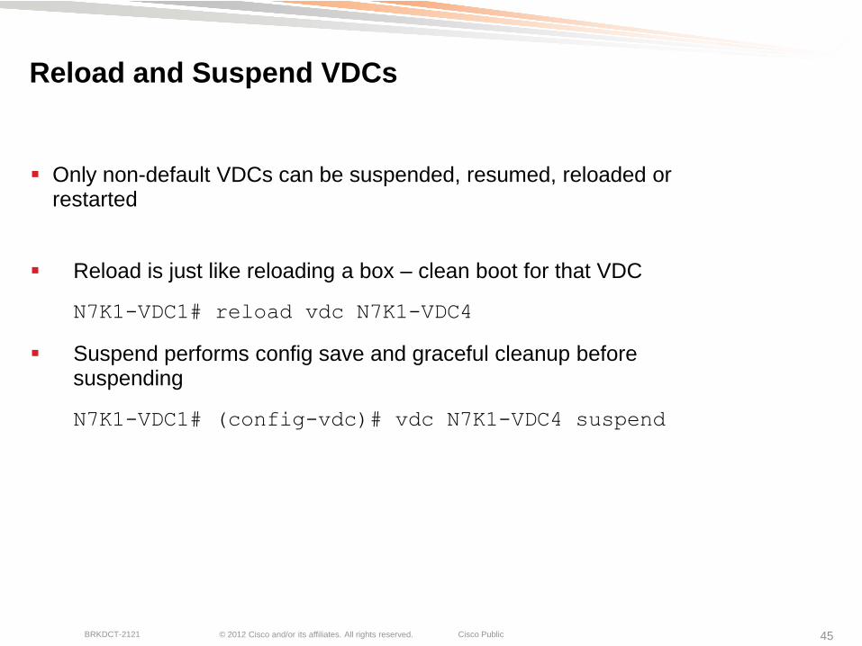
Reload and Suspend VDCs
Only non-default VDCs can be suspended, resumed, reloaded or restarted
Reload is just like reloading a box – clean boot for that VDC
N7K1-VDC1# reload vdc N7K1-VDC4
Suspend performs config save and graceful cleanup before suspending
N7K1-VDC1# (config-vdc)# vdc N7K1-VDC4 suspend
© 2012 Cisco and/or its affiliates. All rights reserved. Cisco Public BRKDCT-2121 46
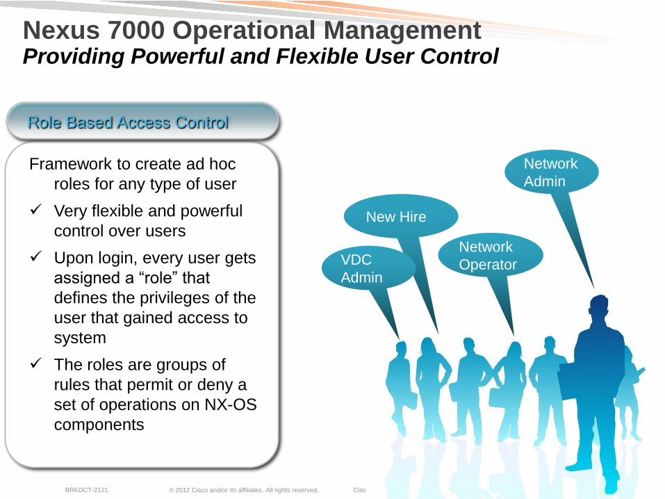
Nexus 7000 Operational Management Providing Powerful and Flexible User Control
Framework to create ad hoc
roles for any type of user
Very flexible and powerful
control over users
Upon login, every user gets
assigned a ―role‖ that
defines the privileges of the
user that gained access to
system
The roles are groups of
rules that permit or deny a
set of operations on NX-OS
components
Role Based Access Control
New Hire
Network
Operator
Network
Admin
VDC
Admin

© 2012 Cisco and/or its affiliates. All rights reserved. Cisco Public BRKDCT-2121 47
Virtual Device Contexts VDC Administration
4 Named Default Roles
- network-admin
- network-operator
- vdc-admin
- vdc-operator
Admin has all rights (read-write)
Operator has read only rights
Roles defined for Priv-15 through 0
- Ease integration into TACACS structure

© 2012 Cisco and/or its affiliates. All rights reserved. Cisco Public BRKDCT-2121 48
VDC Leading Practices
VDC2 Agg1
VDC4 Test
VDC1 Admin
VDC3 Acc1
Nexus7K(config-vdc)# ha-policy dual-sup <policy> single-sup <policy>
Nexus7K(config-vdc)# limit-resource vlan minimum <#> maximum <#>
Utilize a linecard per VDC for improved HA and VDC isolation
Customize VDC HA policy and resource configurations as necessary
Dual-sup default is switchover and single-sup default is restart
8GB of RAM may be required depending on number of VDCs and features enabled – Reference URL at the end
Reserve VDC 1 (default) as the administrative VDC
On VDC 1, assign accounts with minimum privileges necessary to accomplish operational tasks

© 2012 Cisco and/or its affiliates. All rights reserved. Cisco Public BRKDCT-2121 49
Out-of-Band Management Network
Use the management VRF on the Nexus 7000 for all management system connectivity
VDC2 Agg1
VDC3 Agg2
VDC1 Admin
VDC2 Agg1
VDC3 Agg3
VDC1 Admin
Mgmt0 Mgmt0
OOB Mgmt Network
Sys Mgmt server
Separate physical infrastructure is
ideal
Mgmt0 Mgmt0
Mgmt0 x2 Mgmt0 x2
Agg1a Agg1b
Acc1 Acc2
Core2 Core1
OOB Mgmt Dist
L3
CMP x2 CMP x2
Mgmt0 x2 Mgmt0 x2
mgmt1 mgmt2 Management VRF
Default VRF
Use mgmt0 or Connectivity Management
Processor (CMP) ports…or both!
Mgmt0 IP address for default and non-
default VDCs must be from same subnet
Assign different IP address for redundant
CMP (same IP address for redundant
mgmt0 interface)
Doesn‘t preclude the use of in-band
management (Loopback, VLAN, etc)
Common segment in the box
© 2012 Cisco and/or its affiliates. All rights reserved. Cisco Public BRKDCT-2121 50
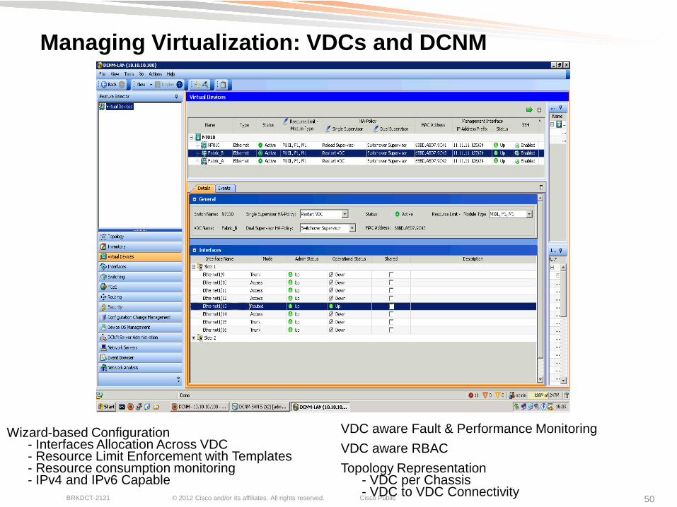
VDC aware Fault & Performance Monitoring
VDC aware RBAC
Topology Representation - VDC per Chassis - VDC to VDC Connectivity
Managing Virtualization: VDCs and DCNM
Wizard-based Configuration - Interfaces Allocation Across VDC - Resource Limit Enforcement with Templates - Resource consumption monitoring - IPv4 and IPv6 Capable

Consolidation with VDCs
© 2012 Cisco and/or its affiliates. All rights reserved. Cisco Public BRKDCT-2121 52
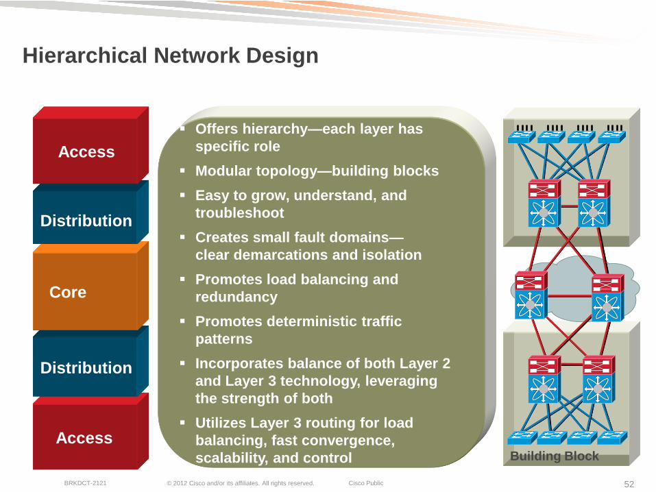
Hierarchical Network Design
Building Block
Access
Distribution
Core
Distribution
Access
Offers hierarchy—each layer has
specific role
Modular topology—building blocks
Easy to grow, understand, and
troubleshoot
Creates small fault domains—
clear demarcations and isolation
Promotes load balancing and
redundancy
Promotes deterministic traffic
patterns
Incorporates balance of both Layer 2
and Layer 3 technology, leveraging
the strength of both
Utilizes Layer 3 routing for load
balancing, fast convergence,
scalability, and control
© 2012 Cisco and/or its affiliates. All rights reserved. Cisco Public BRKDCT-2121 53
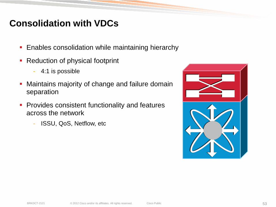
Consolidation with VDCs
Enables consolidation while maintaining hierarchy
Reduction of physical footprint
- 4:1 is possible
Maintains majority of change and failure domain separation
Provides consistent functionality and features across the network
- ISSU, QoS, Netflow, etc

© 2012 Cisco and/or its affiliates. All rights reserved. Cisco Public BRKDCT-2121 54
Consolidation with VDCs (cont)
Considerations
- VDC to forwarding engine mapping
- Single chassis is still a single point of failure
- Highly available – yes, but still a single chassis
- EPLD Upgrade impact on VDCs – multiple modules recommended
- MAC table sizing bound to ―lowest common denominator‖
- Limited number of SPAN sessions
- ACL Capture can help in many instances
© 2012 Cisco and/or its affiliates. All rights reserved. Cisco Public BRKDCT-2121 55
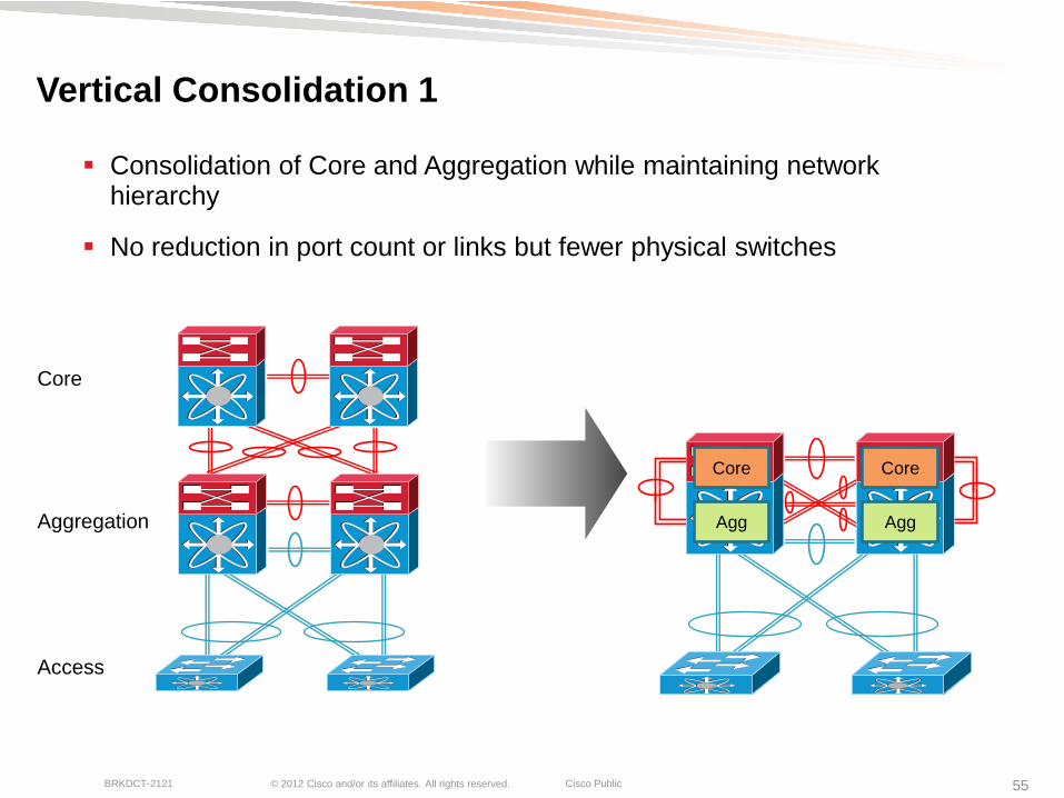
Vertical Consolidation 1
Consolidation of Core and Aggregation while maintaining network hierarchy
No reduction in port count or links but fewer physical switches
Core
Aggregation
Access
Core Core
Agg Agg

© 2012 Cisco and/or its affiliates. All rights reserved. Cisco Public BRKDCT-2121 56
Vertical Consolidation 2
Consolidation of Core, Aggregation and Access while maintaining network hierarchy
Plan accordingly for port/ASIC allocation – might need more cards than you think!
Core
Aggregation
Access
Core Core
Agg Agg
Access Access

Segmentation with VDCs

© 2012 Cisco and/or its affiliates. All rights reserved. Cisco Public BRKDCT-2121 58
Internet Edge/DMZ/Core
Option to meet multiple needs – XL VDC, DMZ and Core
Maintains security model with logical separation
Internet
Edge (XL)
DMZ
Internet
Edge(XL)
Internet Edge
(XL)
DMZ DMZ
Core Core
Internet
Core
Internet

© 2012 Cisco and/or its affiliates. All rights reserved. Cisco Public BRKDCT-2121 59
MPLS and VDCs
Secure and flexible way of software process partitioning
All MPLS features are VDC aware
Each VDC operates as separate MPLS router (LSR):
No internal communication between VDCs
Multiple logical P / PE routers can be configured
Each VDC has independent label space for prefix labels: LDP, VPN, TE
Note: per-VRF VPN labels - globally significant for whole chassis, all others are locally significant to VDC
VDC 1
VDC 2
VDC 3
VDC 4
Key considerations
Kernel
Infrastructure
© 2012 Cisco and/or its affiliates. All rights reserved. Cisco Public BRKDCT-2121 60
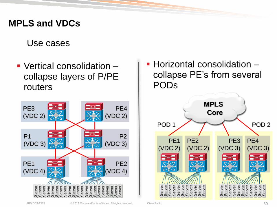
MPLS and VDCs
Vertical consolidation – collapse layers of P/PE routers
Horizontal consolidation – collapse PE‘s from several PODs
Use cases
Serv
er
Serv
er
Serv
er
Serv
er
Serv
er
Serv
er
Serv
er
Serv
er
Serv
er
Serv
er
Serv
er
Serv
er
Serv
er
Serv
er
Serv
er
P1
(VDC 3)
PE3
(VDC 2)
Serv
er
Serv
er
Serv
er
Serv
er
Serv
er
Serv
er
Serv
er
Serv
er
Serv
er
Serv
er
Serv
er
Serv
er
Serv
er
Serv
er
Serv
er
PE1
(VDC 4)
P2
(VDC 3)
PE4
(VDC 2)
PE2
(VDC 4)
PE1
(VDC 2)
Serv
er
Serv
er
Serv
er
Serv
er
Serv
er
Serv
er
Serv
er
Serv
er
Serv
er
Serv
er
Serv
er
Serv
er
Serv
er
Serv
er
Serv
er
Serv
er
Serv
er
Serv
er
Serv
er
Serv
er
Serv
er
Serv
er
PE3
(VDC 3)
PE2
(VDC 2)
PE4
(VDC 3)
MPLS
Core
POD 1 POD 2

Advanced Applications with VDCs
© 2012 Cisco and/or its affiliates. All rights reserved. Cisco Public BRKDCT-2121 62
VDC Functionality with Features
Using VDCs resolves some hardware restrictions required for features like OTV
VDCs can provide a migration strategy to new hardware and line cards
VDCs provide consolidation and separation that makes storage administrators comfortable – virtual MDS
VDC allows us to do things that allow us to solve layer 8-10 issues

Overlay Transport Virtualization (OTV)

© 2012 Cisco and/or its affiliates. All rights reserved. Cisco Public BRKDCT-2121 64
Overlay Transport Virtualization
OTV is a ―MAC in IP‖ technique to extend Layer 2 domains OVER ANY TRANSPORT
Protocol Learning
Built-in Loop Prevention
Preserve Failure
Boundary
Site Independence
Automated Multi-homing
Dynamic Encapsulation
No Pseudo-Wire State
Maintenance
Optimal Multicast
Replication
Multipoint Connectivity
Point-to-Cloud Model
First platform to support OTV!
Nexus 7000

© 2012 Cisco and/or its affiliates. All rights reserved. Cisco Public BRKDCT-2121 65
OTV at the Aggregation Layer
No universal response where to place the OTV Edge Device
Main Options:
- OTV at the Core Layer
- OTV at the Aggregation Layer (most common – discussed in this presentation)
OTV Design Options
OTV Edge Device
L2
L3
Transport Infrastructure
OTV OTV

© 2012 Cisco and/or its affiliates. All rights reserved. Cisco Public BRKDCT-2121 66
OTV and SVI Separation
Guideline: The current OTV implementation on the Nexus 7000 requires the separation between SVI routing and OTV encapsulation for a given VLAN
This separation can be achieved with having two separate devices to perform these two functions
An alternative, cleaner and less intrusive solution is the use of Virtual Device Contexts (VDCs) available with Nexus 7000 platform:
- A dedicated OTV VDC to perform the OTV functionalities
- The Aggregation-VDC used to provide SVI routing support
Aggregation OTV
VDC
OTV
VDC L2
L3

© 2012 Cisco and/or its affiliates. All rights reserved. Cisco Public BRKDCT-2121 67
OTV and SVI Separation VDC Models
Two different deployment models:
OTV Appliance on a Stick
Inline OTV Appliance
Join Interface
Internal Interface
OTV Appliance on a Stick
OTV
VDC
Common Uplinks
for Layer3 and DCI
L2
L3 SVIs
Inline OTV Appliance
Uplinks to the
Layer3 Transport
Dedicated
Uplink for DCI
OTV
VDC
L2
L3 SVIs
No difference in OTV functionality between the two models
The Inline OTV Appliance requires availability of Core downstream links

© 2012 Cisco and/or its affiliates. All rights reserved. Cisco Public BRKDCT-2121 68
Aggregation
Core
Access
OTV at the Aggregation Layer
DC Core performs only Layer 3 role
STP and unknown unicast domains isolated between PODs
Intra-DC and inter-DC LAN extension provided by OTV
Ideal for single aggregation block topology
VPC OTV VDC OTV VDC
VPC OTV VDC OTV VDC
SVIs SVIs SVIs SVIs
Recommended for Greenfield
Join Interface
Internal Interface
Virtual Overlay
Interface

© 2012 Cisco and/or its affiliates. All rights reserved. Cisco Public BRKDCT-2121 69
OTV at the Aggregation Layer

© 2012 Cisco and/or its affiliates. All rights reserved. Cisco Public BRKDCT-2121 70
OTV at the Aggregation Layer
Data Center B
VPC OTV VDC OTV VDC
VPC OTV VDC OTV VDC
VPC OTV VDC OTV VDC
Data Center A
Branch
Office
CTS Encrypted
© 2012 Cisco and/or its affiliates. All rights reserved. Cisco Public BRKDCT-2121 71
OTV at the Aggregation Layer
Aggregation
Core
Def GWY
Firewall Firewall
OTV OTV
Def GWY
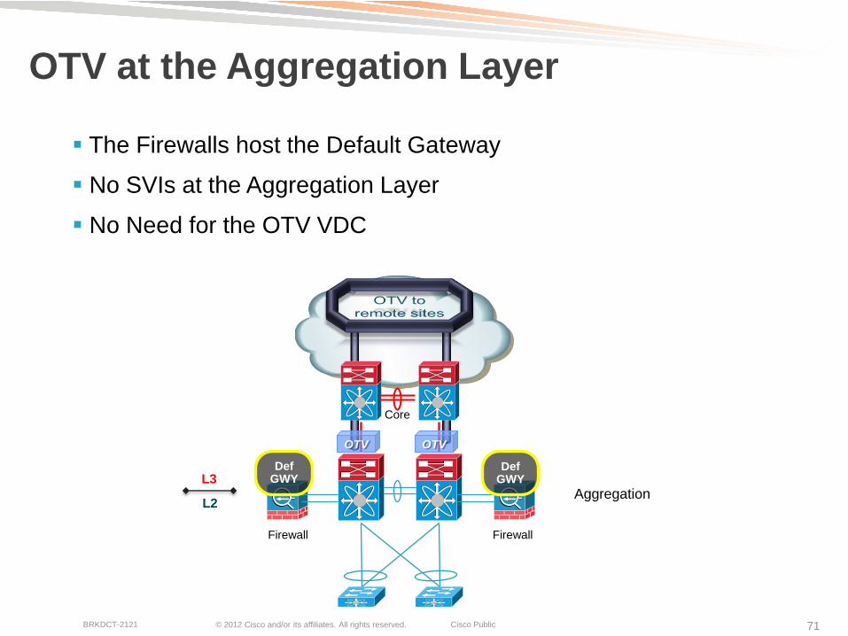
The Firewalls host the Default Gateway
No SVIs at the Aggregation Layer
No Need for the OTV VDC
L2
L3

Fibre Channel over Ethernet (FCoE)

© 2012 Cisco and/or its affiliates. All rights reserved. Cisco Public BRKDCT-2121 73
FCoE Benefits
Fibre Channel over Ethernet (FCoE)
Mapping of FC frames over Ethernet
Enables FC to run on a lossless Ethernet
Wire Server Once
Fewer cables and adapters
Software Provisioning of I/O
Interoperates with existing SANs
No gateway—stateless
Standard – June 3, 2009
Fibre
Channel
Ethernet

© 2012 Cisco and/or its affiliates. All rights reserved. Cisco Public BRKDCT-2121 74
Traditional Data Center Design
Physical and Logical separation of LAN and SAN traffic
Additional Physical and Logical separation of SAN fabrics
Purposely Built Networks
- LAN: Loss and Out of Order Tolerant
- SAN: Loss and Out of Order Intolerant
Limited in Scale
Ethernet LAN and Fibre Channel SAN
HBA
L2
L3
NIC
Isolation Convergence
Fabric ‗A‘ Fabric ‗B‘
FC
MDS 9000
FC
Ethernet
© 2012 Cisco and/or its affiliates. All rights reserved. Cisco Public BRKDCT-2121 75
Converged FCoE link
Dedicated FCoE link
FC
Ethernet
Converged Access
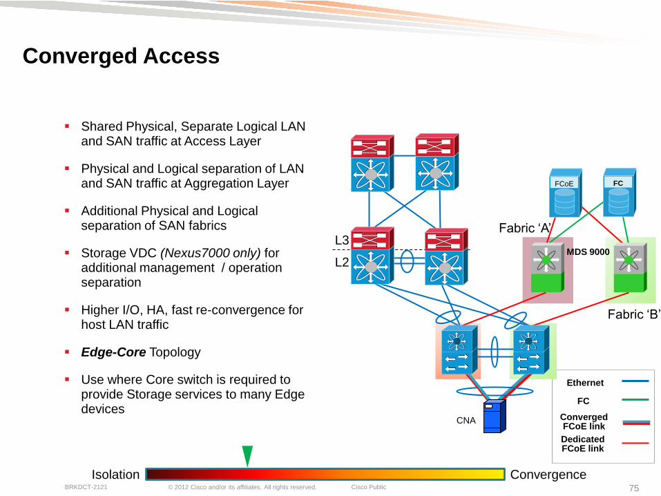
Shared Physical, Separate Logical LAN and SAN traffic at Access Layer
Physical and Logical separation of LAN and SAN traffic at Aggregation Layer
Additional Physical and Logical separation of SAN fabrics
Storage VDC (Nexus7000 only) for additional management / operation separation
Higher I/O, HA, fast re-convergence for host LAN traffic
Edge-Core Topology
Use where Core switch is required to provide Storage services to many Edge devices
Isolation Convergence
Fabric ‗B‘
L2
L3
CNA
Fabric ‗A‘
FC FCoE
MDS 9000
© 2012 Cisco and/or its affiliates. All rights reserved. Cisco Public BRKDCT-2121 76
Converged Network Fabrics w/ Dedicated Links
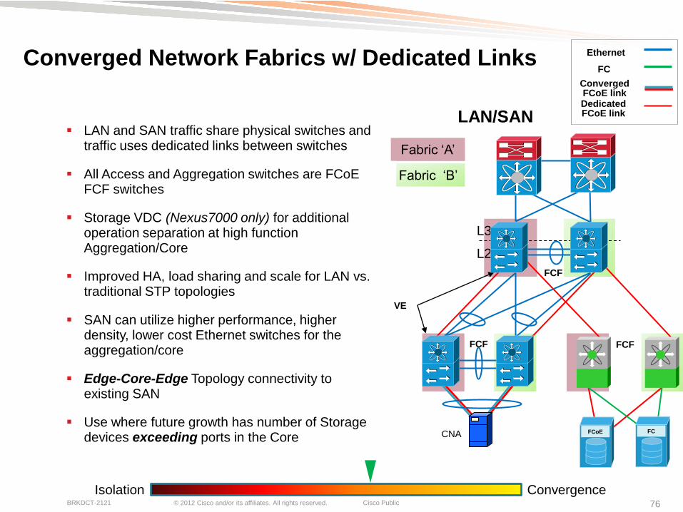
LAN and SAN traffic share physical switches and traffic uses dedicated links between switches
All Access and Aggregation switches are FCoE FCF switches
Storage VDC (Nexus7000 only) for additional operation separation at high function Aggregation/Core
Improved HA, load sharing and scale for LAN vs. traditional STP topologies
SAN can utilize higher performance, higher density, lower cost Ethernet switches for the aggregation/core
Edge-Core-Edge Topology connectivity to existing SAN
Use where future growth has number of Storage devices exceeding ports in the Core
Isolation Convergence
…
…
L2
L3
CNA FC FCoE
FCF FCF
FCF
VE
Fabric ‗A‘
Fabric ‗B‘
LAN/SAN
Converged FCoE link Dedicated FCoE link
FC
Ethernet

© 2012 Cisco and/or its affiliates. All rights reserved. Cisco Public BRKDCT-2121 77
Converged Network Fabrics with Dedicated Links
LAN and SAN traffic share physical switches and traffic use dedicated links between switches
All Access and Aggregation switches are FCoE FCF switches
Storage VDC (Nexus7000 only) for additional operational separation at high function Aggregation/Core
Improved HA, load sharing and scale for LAN vs. traditional STP topologies
SAN can utilize higher performance, higher density, lower cost Ethernet switches for the Edge, Aggregation/Core
Standardize on platform, OS and I/O
Edge-Core-Edge Topology with scalable and dense Ethernet switches at the Edge
FC connectivity only available on Nexus 5000
Isolation Convergence
…
…
L2
L3
CNA FC FCoE
FCF FCF
FCF
VE
Fabric ‗A‘
Fabric ‗B‘
LAN/SAN
Converged FCoE link
Dedicated FCoE link
FC
Ethernet

© 2012 Cisco and/or its affiliates. All rights reserved. Cisco Public BRKDCT-2121 78
Data Center Design with E-SAN
Same topologies as existing networks, but using Nexus Unified Fabric Ethernet switches for SANs
Physical and Logical separation of LAN and SAN traffic
Additional Physical and Logical separation of SAN fabrics
Ethernet SAN Fabric carries FC/FCoE & IP based storage (iSCSI, NAS, …)
Common components: Ethernet Capacity and Cost
Standardize on OS, I/O and Platform
Storage administrators in Large Data Centers almost always prefer this model (distinct storage management plane)
Isolation Convergence
Fabric ‗B‘
CNA
L2
L3
NIC
or
CNA
Fabric ‗A‘
FCoE
Ethernet

© 2012 Cisco and/or its affiliates. All rights reserved. Cisco Public BRKDCT-2121 79
Converged Network with Dedicated Links
FabricPath enabled for LAN traffic
Dual Switch core for SAN A & SAN B
All Access and Aggregation switches are FCoE FCF switches
Dedicated links between switches are VE Ports
Storage VDC (Nexus 7000 only) for additional operation separation at high function agg/core
Improved HA and scale over vPC (ISIS, RPF, … and N+1 redundancy)
SAN can utilize higher performance, higher density, lower cost Ethernet switches
FC connectivity only available on Nexus 5000
L2
L3
CNA
Isolation Convergence
FC FCoE
Fabric ‗A‘
Fabric ‗B‘
FCF
FCF
FCF
FCF
VE
Converged FCoE link
Dedicated FCoE link
FC
Ethernet
FabricPath

FabricPath

© 2012 Cisco and/or its affiliates. All rights reserved. Cisco Public BRKDCT-2121 81
Layer 3 strengths
Leverage bandwidth
Fast convergence
Highly scalable
Introducing Cisco FabricPath An NX-OS Innovation for Layer 2 Networks
Simplicity Flexibility Bandwidth Availability Cost
Layer 2 strengths Simple configuration
Flexible provisioning
Low cost
Resilience
Fabric
Path
© 2012 Cisco and/or its affiliates. All rights reserved. Cisco Public BRKDCT-2121 82
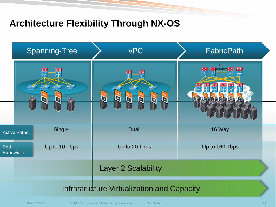
Architecture Flexibility Through NX-OS
Spanning-Tree vPC FabricPath
Pod
Bandwidth
Active Paths
Up to 10 Tbps Up to 20 Tbps Up to 160 Tbps
Single Dual 16 Way
Infrastructure Virtualization and Capacity
Layer 2 Scalability
16
Switches
© 2012 Cisco and/or its affiliates. All rights reserved. Cisco Public BRKDCT-2121 83
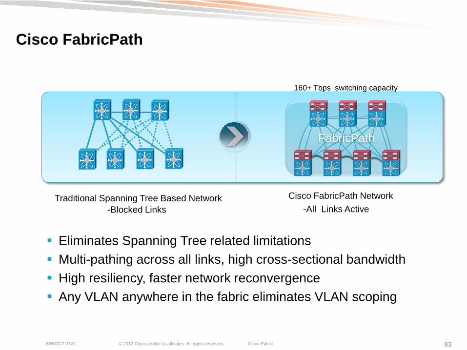
Cisco FabricPath
-All Links Active
Traditional Spanning Tree Based Network
-Blocked Links
Cisco FabricPath Network
160+ Tbps switching capacity
Eliminates Spanning Tree related limitations
Multi-pathing across all links, high cross-sectional bandwidth
High resiliency, faster network reconvergence
Any VLAN anywhere in the fabric eliminates VLAN scoping
FabricPath

© 2012 Cisco and/or its affiliates. All rights reserved. Cisco Public BRKDCT-2121 84
L3
Parallel FabricPath Core
Motivations: Consolidation and whole-network scale
Removes access connections and aggregation mesh limitations
L3
FabricPath
VPC+ VPC+
FabricPath Core
VPC
Meshed agg model overly complex after a certain point
Add FabricPath core parallel to L3 core to interconnect FabricPath Pods

© 2012 Cisco and/or its affiliates. All rights reserved. Cisco Public BRKDCT-2121 85
L3 L3
Parallel FabricPath Core with VDCs
L3
FabricPath
VPC+ VPC+
FabricPath Core VDC
FabricPath Core VDC
Layer 3 Core VDC Layer 3
Core VDC
VPC
Exact same model as prior slide but with VDCs instead of separate physical switches
Note – VDCs not required for FabricPath
© 2012 Cisco and/or its affiliates. All rights reserved. Cisco Public BRKDCT-2121 86
Summary
VDCs Unlock the full potential of Nexus 7000
VDCs can be used for many uses
- Consolidation – vertical and horizontal
- Security and segmentations
- Advanced applications
Overlay Transport Virtualization (OTV)
Fibre Channel over Ethernet (FCoE)
FabricPath

© 2012 Cisco and/or its affiliates. All rights reserved. Cisco Public BRKDCT-2121 87
Course Objective
What we learned…
VDC Configuration Guidelines
Common VDC Use Cases
How to use VDCs with Advanced Applications

© 2012 Cisco and/or its affiliates. All rights reserved. Cisco Public BRKDCT-2121 88
Additional References
VDC White Paper on CCO
http://www.cisco.com/en/US/prod/collateral/switches/ps9441/ps9402/ps9512/White_Paper_Tech_Overview_Virtual_Device_Contexts.html
8GB RAM Flowchart
http://www.cisco.com/en/US/docs/switches/datacenter/sw/5_x/nx-os/release/notes/51_nx-os_release_note.html#wp86458
Common Criteria Certification #10349
- http://www.niap-ccevs.org/st/vid10349/
FIPS 140-2
- http://csrc.nist.gov/groups/STM/cmvp/documents/140-1/140InProcess.pdf
NSS Labs
http://www.nsslabs.com/
Follow us on Twitter
@CiscoNexus7000

Recommended Reading
© 2012 Cisco and/or its affiliates. All rights reserved. Cisco Public BRKDCT-2121 90
Please complete your Session Survey
Don't forget to complete your online session evaluations after each session.
Complete 4 session evaluations & the Overall Conference Evaluation
(available from Thursday) to receive your Cisco Live T-shirt
Surveys can be found on the Attendee Website at www.ciscolivelondon.com/onsite
which can also be accessed through the screens at the Communication Stations
Or use the Cisco Live Mobile App to complete the
surveys from your phone, download the app at
www.ciscolivelondon.com/connect/mobile/app.html
We value your feedback
http://m.cisco.com/mat/cleu12/
1. Scan the QR code
(Go to http://tinyurl.com/qrmelist for QR code reader
software, alternatively type in the access URL above)
2. Download the app or access the mobile site
3. Log in to complete and submit the evaluations

© 2012 Cisco and/or its affiliates. All rights reserved. Cisco Public BRKDCT-2121 91
Thank you.