viking johnson products
DESCRIPTION
VJ CouplingsTRANSCRIPT

DESIGN DATA
DE
SI
GN
D
AT
A

Wo r l d l e a d e r s i n P i p e J o i n t s
& R e p a i r P r o d u c t e n g e r n e e r i n g
Viking Johnson’s Corporate vision is...
...To help our Customers to enhance and improve their asset
networks by providing them with innovative, high quality,
user-friendly solutions.
To continuously improve our products, processes and people
to maintain and improve our standing and reputation within
the Industries that we serve.
To consistently exceed the expectations of our Customers,
Distributors, Suppliers and Employees to assure a profitable
long-term future for all concerned.
Viking Johnson’s primary market places are the Water and
Gas Industries, Worldwide. We serve these markets through
an International network of Distributors and Agents, providing
our ultimate Customers with an invaluable, local service.

3
Glossary of Terms 4
Introduction 5
The Concept 6
System Overview 7
Design Data
Angular Deflection 8 - 9
Setting Gaps 10
Pressure Forces/Coupling Movement Under Pressure 11
Accommodating End Load Forces/ F lexLock /UltraGrip 12
Pipe Supports /Anchored Couplings 13
Centre Register /Inclined Pipelines 14
Shear Strength /Expansion and Contraction/Pipe End Preparation 15
Couplings 16
Stepped Couplings 17
Flange Adaptors 18
Flange Comparison Chart 19
Gaskets 20
Summary of Gaskets 21
Corrosion Protection 22
Chemical Resistance Chart 23
The Viking Johnson Product Range 24 - 27
OD Conversion Chart 28
C o n t e n t s
Tel: +44 (0) 1462 443322

IMPORTANT NOTICEThe technical, performance data, specifications, dimensions and all other information publishedin the Design Data section supersede all previously published information. All data contained herein is subject to change without notice.The information given in the following pages is intended as a general guide to the proper designand installation of practical piping systems using Viking Johnson products. It is not intended as asubstitute for competent, professional advice, which should always be sought in the design of anypiping system. Good piping practice should always prevail and recommended design pressures,temperatures, tolerances and loads should never be exceeded.Special conditions often exist for which the information given here is not specifically suited andspecialist engineering advice should be obtained. As with any other piping system, the specificadvantages and limitations of Viking Johnson products should be considered when designing asystem using Viking Johnson products. The suggestions made here do not set out to give specificsolutions to actual installation problems but to give ideas on which to base your own uniquesolutions.While every effort has been made to ensure its accuracy, Viking Johnson make no express orimplied warranty of any kind in respect of the information contained in this brochure or thematerials referred to herein. Any person making use of the information contained here does soentirely at their own risk and assumes any and all liability resulting from such use. The information contained within this section applies specifically to Viking Johnson products only,and is not intended to apply to any other bolted sleeve type coupling product.
© 2005 by Viking Johnson. Printed in the United Kingdom. No part of this booklet may be reproduced, stored or transmitted,in any form or by any means, electronic, mechanical, photocopying, recording or otherwise,without prior permission of Viking Johnson.
Glossary of Terms
The following abbreviations are used in this brochure:
OD - Pipe outside diameter
NB - Nominal bore
DN - Nominal diameter, in millimetres
PN - Nominal pressure, in bar (1 bar = 0.1 MPa = 0.1 N/mm2 ≈ 14.5 lbf/in2)
CI - Grey cast iron
DI - Ductile iron
PE - Polyethylene
MDPE - Medium density polyethylene (PE80)
HPPE - High performance polyethylene (PE100)
AC - Asbestos cement
GRP - Glass reinforced plastics
uPVC - Unplasticised polyvinyl chloride
PVC-u - Metric uPVC pipe (including Molecular Oriented and Impact Modified)
ABS - Acrylonitrile butadiene styrene
EPDM - Ethylene propylene diene monomer
NBR - Nitrile butadiene rubber
WRAS - Water Regulations Advisory Scheme
PCD - Pitch circle diameter
Tel: +44 (0) 1462 443322

5www.vikingjohnson.com
The Viking Johnson system for joining plain-ended pipes was first introduced to the market in1930 and is now recognised as being second to none in reliability and quality.This brochure provides information useful to designers and engineers involved in the designand specification of piping systems. Full dimensions and material specifications for thevarious Viking Johnson products can be found on our website - www.vikingjohnson.com.Should you require any additional information, please contact our Marketing Department.
The Viking Johnson system is suitable for an enormous range of pipework applications and itis therefore impossible to give a comprehensive list of potential uses. In general terms, thesystem is suitable for virtually any pipeline, above or below ground level, working within thefollowing typical parameters:
Working pressureUp to 100 bar (1450psi), according to size. Up to full vacuum.
Temperature Limited by gasket grade used, but within the range -60°C to +200°C (-75°F to +390°F)
Suitable forWater, gas, oil, petrochemicals, sewage, powdered solids, granular solids, air. Subject togasket grade used and product/pipe limitations.
Location Above or below ground (subject to certain limitations according to product and pipe material).
Backed by many years of design and manufacturing experience, the Viking Johnson system isa complete and cost-effective answer to almost all pipeline installation problems.
Compare the following benefits with those offered by alternative pipe jointing systems:• ISO 9001 certification is proof of our exacting quality standards.
• ISO 14001 certification is proof of our environmental credentials.
• Exclusive Viking Johnson gaskets, moulded to exacting specifications, assure perfectlifetime sealing, meeting all relevant Standards.
• Size range extends from DN15 (0.5") to more than DN5000 (200").
• The Viking Johnson system is designed for plain-ended pipes, eliminating threading,bevelling, welding or flanging.
• The system can joint most types of pipes, valves or meters.
• By specifying Viking Johnson, installation delays caused by adverse weather conditions areovercome, particularly relevant to PE installation.
• You can rely on Viking Johnson products. Their dependability has been demonstrated for75 years in all conditions of service.
• On-site jointing equipment - with Viking Johnson products all you need is a spanner and torque wrench.
• The simplicity of our design assures you of couplings which will assemble quickly, easilyand accurately every time. Company representatives are available to offer technical adviceto the installer.
• As a mechanical jointing system it can eliminate the need for specialist labour or on-site fabrication.
• Viking Johnson couplings are protected for life against corrosion with a range of specialisedcoatings. Please state coating required when ordering.
• Viking Johnson has over 100 agents and distributors worldwide, in addition to an exclusivedistributor network throughout the UK.
In t roduct ion
Tel: +44 (0) 1462 443322

6 [email protected] Tel: +44 (0) 1462 443322
The Concept
Fig. A
Cutaway illustration of Viking Johnsonstraight coupling.
Tightening the bolts compresses the gasket between the end ring and the centre sleeve, orcing the gasket to seal onto the pipe surface.
Fig. B
Fig. D
Gaskets deform to accommodate expansion and contraction.
Flexible gasket and centre sleeve clearance allows angular movement.
Fig. C
All Viking Johnson couplings, flange adaptors, MaxiFit, QuickFit, MegaFit,UltraGrip, FlexLock, AquaGrip (up to DN180) couplings operate on the samebasic compression principle.
How it worksThe Viking Johnson coupling (Fig. A)comprises a centre sleeve located betweentwo end rings. Wedge-shaped elastomericgaskets separate the sleeve and end rings. As the captive ‘D’ head bolts are tightened,the end rings are drawn together,compressing the gaskets between the endrings and the centre sleeve onto thesurface of the pipe to form an effective,leak-proof seal (Fig. B).
FeaturesThe basic concept of the Viking Johnsoncoupling means that it can be used on plain-ended pipe, removing the need for costlyand time-consuming pipe end preparation.The Viking Johnson coupling is also capableof absorbing expansion and contractionwhich occurs in pipelines as a result oftemperature fluctuations, without the needfor special expansion joints (Fig. C). In addition, it can accommodate enoughangular deflection to allow for pipelinemovement or ground settlement, or toprovide for long radius curves without thenecessity of incorporating purpose-madebends (Fig. D).

7Tel: +44 (0) 1462 443322 www.vikingjohnson.com
Pipe materialsMost rigid and semi-rigid pipe materials can bejoined with Viking Johnson coupling products:-steel (including stainless steel), grey cast iron,ductile iron, asbestos cement, uPVC, GRP,concrete, polyethylene and ABS. Of these, the rigid materials with high strengthcapabilities, such as steel, grey cast iron, ductileiron and concrete can be joined using standardViking Johnson couplings without revision to ournormal fitting instructions. Certain lower strength materials, such as claywareand the lower classes of asbestos cement pipe,may need reduced bolt torques to avoid pipedamage. Glass reinforced plastic (GRP) pipe isrelatively flexible and its structure may be damagedby high gasket pressures. Reduced bolt torques arealso recommended for this pipe material (detailsavailable on request).Polyethylene (PE) pipe is produced in various typesand with various performance capabilities.All exhibit the tendency to creep i.e. change shapewhen loaded. The use of standard Viking Johnsoncouplings may result in leakage or pipe pull-out.Viking Johnson AquaGrip and AquaFast productsare both specifically designed to join PE pipe eitherto another PE pipe or to flanged equipment orother pipe materials. Certain sizes of EasiClampare also suitable for use on repairs to PE pipe.UltraGrip may be used on PE pipe if a supportinginternal liner is also used.
Pipe outside diametersDedicated Viking Johnson couplings and flangeadaptors may be specified for any pipe sizebetween DN50 (2") and DN5000 (200"), even foroutside diameters not covered by recognised pipestandards. Since Viking Johnson couplings fit overthe outside of the pipe, it is essential that the ODis specified at time of enquiry/order.
Pipe tolerancesViking Johnson couplings give their optimumperformance when they are a close fit on the pipe.Seal effectiveness depends on the pressure whichthe gasket applies to the pipe surface. Undersizedpipes may mean a loss in pressure rating. Thecoupling schedules in the Dimensional Databrochure give standard pipe OD tolerances whichshould be complied with whenever possible.Many pipe standards quote the main pipe barreltolerance separately from the tolerance on the pipeends. The tolerance quoted in the dimensionschedules in the Dimensional Data brochure relateto pipe ends, and may be smaller than tolerancesmid-barrel. Many steel pipes are made withsubstantially larger OD tolerances than are statedin our coupling schedules in the Dimensional Databrochure (eg. ±1% on diameter). In such circumstances the actual pipe tolerancesshould be discussed with Viking Johnson for advice.
Pipe ovalityModerate ovality, especially in large diameter steelor ductile iron pipes, can frequently be rectified byselective bolt tightening to give a uniform annulargap between pipe and coupling. More severeovality, up to a limit of about ±1% of diameter,may be corrected by jacking, taking care not todamage the internal lining of the pipe. Pipes having local stiffening near the ends may beimpossible to correct for shape by these methodsand good circularity is essential if couplings are tobe fitted successfully.N.B. The Viking Johnson MaxiFit, MegaFit andUltraGrip ranges of Universal Coupling productscan accommodate larger pipe tolerances andovality, see separate brochures for details.
Diameter measurementThe most reliable method of measuring OD is bycircumference measurement. This eliminates the effects of ovality and, provided that ovality is moderate, it is almostalways possible to correct for minor ovality duringassembly. Circumference measurement may becarried out using either a purpose-madecircumference tape which reads out directly as an effective diameter, or it is possible to use anordinary tape wrapped around the pipe and theresulting circumference value converted to effectivediameter by dividing the result by π(= 3.142). If pipe calipers are available, these can give auseful further indication of pipe shape and thepossible need for special sizing of the coupling. If in doubt, contact Viking Johnson for further advice.
Pipe coatingsMany pipes are finished with a coating of somedescription, which can affect pipe O.D. Allowancemust be made for these coatings in themanufacturing size of the coupling, or installationof the coupling may be difficult or impossible. Verythick pipe wrappings (typically several millimetresthick) must be removed at pipe ends so that thecoupling will seat either on the bare pipe or on a high quality thinner paint film. It is importantthat details of the intended pipe corrosionprotection are made known to us when ordering so that the correct size of coupling can beproduced. Alternatively, we must be informed ofthe finished pipe diameter including all coatings,with appropriate tolerances.
Pipe surface finishThe Viking Johnson system relies on good uniformcontact of the gaskets with the pipe surface. It is important to ensure that the pipe ends, in theareas where the coupling gaskets will seat, are freefrom loose surface deposits, bumps, dents, scoremarks, weld beads, flat spots and the like, or thefull pressure capability of the coupling may not be realised.
Working pressureThe working pressure capability of a couplingvaries with its size and construction. It is alsodependent upon correct pipe tolerances andsurface finish. Test pressures are specified in theschedule of dimensions in the Dimensional Databrochure and represent the maximum capability of the Viking Johnson component. Wider pipe ODtolerances than those specified will result in a reduction in pressure capability. For most pipematerials, the actual test pressure will be lowerthan that of the coupling and will be determined bythe pipe capability or class. Similarly the pressurerating of a flange adaptor will be determined by therating of the main flange (eg. PN16 = 16 barworking pressure, 24 bar test).When assembled onto the pipe(s), the pressurerating of the completed assembly will be that ofthe lowest rated component. Under normalcircumstances working pressures are up to 2/3 ofthe maximum test pressure shown in theappropriate schedule. For pressures higher thanthose listed in the schedules in the DimensionalData brochure special couplings can be supplied.
Operating temperatureThe operating temperature of Viking Johnsoncouplings is determined primarily by thetemperature rating of the gaskets. Different gradesof gaskets are available to suit various temperatureranges as well as different chemical resistancerequirements. For details see the Gaskets section(pages 22 and 23 of this brochure). Most Viking Johnson Couplings are supplied withRilsan Nylon 11 coating which has a maximumoperating temperature of 90°C. For higher temperatures, alternative coatingsmay be necessary.Viking Johnson couplings operate at theirmaximum efficiency under conditions of relativelyconstant temperature. If temperature fluctuations occur, retightening ofthe bolts may be required. For this reason, where maintenance-free operation is required,Viking Johnson couplings are not recommendedfor central heating or similar systems, which do
not operate at relatively constant temperature.
Chemical resistanceThe chemical resistance of a Viking Johnsoncoupling is determined by suitability of the gasketsand by the chemical resistance of the internalsurfaces of the coupling sleeve. If the coupling is coated with Rilsan, epoxy, etc. it is necessary to ensure that this material ischemically suitable for contact with the pipecontents. Chemical resistance of the gaskets andcoatings may be checked with the chart on page24 or by contacting Viking Johnson.
System Overv iew

8 [email protected] Tel: +44 (0) 1462 443322
Each Viking Johnson coupling or flangeadaptor will allow for a setting angularity(Ø) as shown in Table 1.1The ability of Viking Johnson couplings toaccommodate angular deflection, either oninstallation or in service, can be used in anumber of valuable ways:a) To take up minor misalignment orlateral displacement in straight pipes, eg.at closing lengths.b) To accommodate ground settlement.c) To lay pipes to long radius curveswithout special bends.
a) Lateral Displacement.Lateral displacement between two pipescan be easily accommodated using twocouplings and an appropriate length ofclosing pipe which can be allowed toangulate (Fig 1.1 & 1.2). A SINGLE COUPLING CANNOTACCOMMODATE LATERALDISPLACEMENT. The length, L, of the closing pipe can be calculated from the closing length Table 1.2.
b) Ground SettlementGround settlement, for example where apipe leaves an underground structure, maybe accommodated using a pair of VikingJohnson couplings. In this case, pipetrenches are excavated below the pipeinvert to allow for pipe bedding. If thisbedding is to be flexible (eg. granular fill),some settlement will inevitably occurwhen the trench is backfilled. (Fig. 1.4)To minimise stresses in pipe 1, coupling Ashould be installed as close as possible tothe structure. The two couplings A and Ballow pipe 2 to angulate to take upsettlement Y. The minimum length of pipe2 is determined using the Closing LengthTable in Table 1.2. The structural strengthof the pipe in bending may need to be considered.Alternatively, a Viking Johnson wallcoupling can be used instead of pipe 1and coupling A.
Lateral displacement (Y) can be accommodatedusing two couplings.
Length of closing pipe (L) depends on maximumangularity (Ø).
Fig. 1.1
Fig. 1.2
SETTING ANGULARITY TABLE - DEDICATED RANGE
Coupling Size Angle Inclination
Up to DN450 (18") ± 6° 1 in 10
Over DN450 - DN600 (18" - 24") ± 5° 1 in 12
Over DN600 - DN750 (24" - 30") ± 4° 1 in 15
Over DN750 - DN1200 (30" - 48") ± 3° 1 in 20
Over DN1200 - DN1800 (48" - 72") ± 2° 1 in 30
Over DN1800 (72") ± 1° 1 in 60
Flange Adaptor Size
Up to DN450 (18") ± 3° 1 in 20
Over DN450 - DN600 (18" - 24") ± 2.5° 1 in 24
Over DN600 - DN750 (24" - 30") ± 2° 1 in 30
Over DN750 - DN1200 (30" - 48") ± 1.5° 1 in 40
Over DN1200 - DN1800 (48" - 72") ± 1° 1 in 60
Over DN1800 (72") ± 0.5° 1 in 120
The above schedules represent the maximum angular deflection for each sizerange and should only be used when the pipes will not move in service. For other conditions it is recommended to halve these figures to allow for in-service flexibility.
Angular deflection (ø). Up to 6° in smaller pipes, reducing to 1° in larger diameters.
Table 1.1
Fig. 1.3
Angular Def lect ion

9Tel: +44 (0) 1462 443322 www.vikingjohnson.com
c) Long Radius CurvesUsing Viking Johnson couplings it ispossible to lay a pipeline to long radiuscurves, taking a small angular deflection ateach coupling, without the need for speciallarge-angle bends with associated thrustblocks. This method can be used to avoidmajor obstacles on cross-country pipelinesor follow the line of roads or streams, etc.using the equation given below.
3m (10ft) 29m (95ft) 34m (110ft) 43m (140ft) 57m (185ft) 86m (280ft) 172m (565ft)
6m (20ft) 57m (187ft) 69m (225ft) 86m (280ft) 115m (375ft) 172m (565ft) 344m (1130ft)
9m (30ft) 86m (280ft) 103m (335ft) 129m (425ft) 172m (565ft) 258m (845ft) 516m (1690ft)
12m (40ft) 115m (375ft) 138m (450ft) 172m (565ft) 229m (750ft) 344m (1130ft) 688m (2260ft)
Long radius curves can be accommodatedwithout special bends.
Fig. 1.4
Table 1.2
Table 1.3
Fig. 1.5
Ground Settlement. Displacement can be accommodated using two couplings and
EXAMPLE: Pipe OD= 711mm EXAMPLE: Pipe OD = 28"Lateral displacement to be accommodated = 90mm Lateral displacement to be accommodated = 4"Minimum closing length = 90 x 15 = 1350mm Minimum closing length = 4 x 15 = 60"
NOTE: For Viking Johnson flange adaptors these lengths must be doubled.
R= L2 sin 1/2 ø
ø = 2 sin-1 L2 R
where L = pipe lengthø = angular deflectionr = radius of curve
CLOSING LENGTH TABLE (see Fig. 1.2 & 1.3)
Pipe Nominal Diameter L, Minimum Length (mm)Up to DN450 (18") Displacement Y x 10Over DN450 - DN600 (18" - 24") Displacement Y x 12Over DN600 - DN750 (24" - 30") Displacement Y x 15Over DN750 - DN1200 (30" - 48") Displacement Y x 20Over DN1200 - DN1800 (48" - 72") Displacement Y x 30Over DN1800 (72") Displacement Y x 60
See minimum radius Table 1.3
NB: In an above ground pipeline, lateral pressure thrusts will need to be restrained by the support system. Buried pipes laid to a curvewill normally receive sufficient support from the trench backfill material.
( )
Y A B
MINIMUM RADIUS TABLE
Pipe diameter <DN450 DN450-600 DN600-750 DN750-1200 DN1200-1800 >DN180018" 18" - 24" 24" - 30" 30" - 48" 48" - 72" 72"
Nominal Angle ø 6° 5° 4° 3° 2° 1°
Pipe Length (L) Minimum Radius (R)
Other radii may be calculated using the formula given above. NOTE: These minimum radii do not allow any in-service movement.
Or

10 [email protected] Tel: +44 (0) 1462 443322
Viking Johnson couplings are used to joinpipes flexibly, so that if there is pipe orground movement during the life of thepipeline, the coupling will accommodatethis without leakage. However, suchmovement will result in relativelongitudinal and/or angular displacementof the pipes within the coupling.Under normal conditions, adjacent pipeends should not make contact with eachother in service. If there is insufficient gapso that pipes do touch, the pipeline willtend to buckle as temperatures increaseand pipe end damage may occur. At theother extreme, if the pipe end gap is toolarge on installation, there is a risk thatpipes may pull out past the gasket(s) ofthe coupling leading to leakage and failureof the pipeline.It is therefore necessary to ensure thatpipe end gaps are set within specifiedlimits during installation of the coupling to
ensure that neither situation occurs.We give a Recommended Setting Gap forall sizes of Viking Johnson coupling andflange adaptor, which specifies the normalinitial gap between adjacent pipe endssuch that if the full recommendedangularity or expansion occurs in service,the pipe ends should not touch togethercausing damage. (see Table 1.4)Similarly, we also give a MaximumRecommended Gap which ensures thateven with full recommended angularitythere should not be any risk of pipe endspulling out past the coupling or flangeadaptor gasket, leading to leakage. (see Fig. 1.6 and Table 1.4)For pipes above ground, it is possible forunanchored pipes to shunt together afterinstallation, opening up a large gapbetween pipes at certain points. Such pipemovement must be controlled to ensurethat the Maximum Permissible Gap is not
exceeded, or there may be a risk of thepipe pulling out of the coupling. Soilfriction acting on pipes laid below groundnormally prevents any such pipe shuntingmovement.The Maximum Permissible Gap, measuredon the centreline, should not be exceededin service. Consideration of actual thermalmovement or deflection conditions maylead to different initial setting gaps.When couplings are specified with alocating plug or centre register, theRecommended Setting Gap should beincreased by the diameter of the pin orplug (10mm (0.375") or 13mm (0.5")).However, the Maximum Permissible Gapshould not be increased.Where the standard Viking Johnson sleevelength is found to be insufficient, longersleeved couplings and flange adaptors canbe supplied.
Recommended Setting GapCoupling Nominal Couplings Flange Adaptors Maximum Sleeve Width Size (D) Permissible Gap (x)
80mm (3") d ≤ DN50 (d ≤ 2") 15mm (0.5") 20mm (0.75") 30mm (1.25")
100mm (4") DN50 < d ≤ DN300 (2" < d ≤ 12") 20mm (0.75") 20mm (0.75") 40mm (1.5")
150mm (6") DN300 < d ≤ DN900 (12" < d ≤ 36") 25mm (1") 25mm (1") 50mm (2")
178mm (7") DN900 ≤ d ≤ DN1800 (36" ≤ d ≤ 72") 40mm (1.5") 30mm (1.25") 75mm (3")
254mm (10") d > DN1800 (d > 72") 55mm (2.15") 30mm (1.25") 115mm (4.5")
Fig. 1.6
Table 1.4
a) Pipes laid straight with equal setting gaps. b) Accumulated gap (X) on straight pipeline must not exceed maximum permissible value given in Setting Gap Table.
SETTING GAP TABLE
Set t ing Gaps

11Tel: +44 (0) 1462 443322 www.vikingjohnson.com
All pipelines under pressure are subject tolongitudinal forces which tend to separatethe component parts of the pipeline.Consider the case of pressure acting on a blank end (Fig 1.7). The force, F,necessary to prevent pipe separation is given by:
It is important to appreciate themagnitude of the end thrusts which canresult from internal pressure in a pipeline.These longitudinal forces are particularlyimportant in flexibly jointed pipelines,such as those jointed with Viking Johnsoncouplings. The pipeline designer mustcarefully consider not only the magnitudeof these forces but also the means ofresisting them to prevent failure of thepipeline.
Pressure thrusts will be produced at allchanges of direction, eg. bends, tees, etc.and at cap ends, valves and reducers.Unless these thrusts are restrained locallyat the point at which they are developed,pipe components may move under theload, leading to failure.
VIKING JOHNSON COUPLINGS DO NOT RESIST LONGITUDINALTHRUST LOADINGS, AND PIPE PULL-OUT WILL OCCUR UNLESS THELOADS ARE RESTRAINED BY OTHERMEANS.
Even small diameter pipes may pull out ofcouplings at modest pressures unlessproper external restraint is provided,especially if the pipe system is subjectedto temperature or pressure fluctuations,vibration or external loadings.
With surface or above-ground pipelines itis generally necessary to take full accountof the thrusts produced by internalpressures and to restrain them with thrustblocks, anchorages or tie bars. At a bend,there is a force, R, tending to push thebend outwards (Fig. 1.8). In this case there must be sufficientanchorage to resist resultant force R. In a buried system a thrust block (Fig. 1.8a) may be used to resist R.
Longitudinal pressure forces acting at a bend.
Concrete thrust block for retaining bend.
Fig. 1.8
Fig. 1.8a
Internal pressure will mainly cause pipemovement if there is inadequate restraint,however it can also cause couplingmovement. A Viking Johnson steppedcoupling is in effect a reducer, and internalpressure will tend to push it towards thesmaller diameter pipe. Under normalcircumstances, i.e. modest diameterreduction, buried service, standard waterpressures etc., soil and pipe friction aresufficient to prevent coupling movement.However, for larger diameter and for aboveground service, and in particular higherpressures, the pressure thrust acting on thestepped coupling sleeve can be sufficient tocause coupling movement and consequentdisengagement. Positive steps must betaken to restrain the coupling to preventmovement. This may take the form ofharness rods, stops on the pipe or withinthe coupling or encasement in concrete.For further advice, please contact Viking Johnson Technical Support.
IMPORTANTIt is important to note that action must betaken to resist end loadings due to pressureforces. Very low pressures may, in certaincases, be resisted by the friction betweencoupling and pipe, but even such forcesshould normally be resisted by other means.
Longitudinal pressure forces acting at a blank end.
Fig. 1.7
R=p π d2
sinø
2 2
where d = pipe outside diameter
p = internal pressure
and ø = angle of the bend
NOTE: Any consistent set of units is suitable.
F =p π d2
4Where d = pipe ODp = internal pressure.
Example: d = 508mm OD. p = 16 bar = 1.6 N/mm2
Then F = 1.6 x π x 5082=
4324293 N = 324.3 kN = 33.07 tonnes
Pressure Forces
Coupl ing MovementUnder Pressure

12 [email protected] Tel: +44 (0) 1462 443322
Below ground, pipe thrusts can normallybe restrained by means of concrete thrustblocks at bends, valves, etc. However,above ground this is more difficult. In such circumstances it may be necessaryto provide a harness assembly, attached tothe pipes on both sides of the coupling.This consists of one or more pairs of tiebolts located in either harness lugs weldedto the pipe (Fig. 1.9 (a)) or attached byother means, eg. flanges cast on. Theharness assembly must be designed to suitthe actual magnitude of the pressurethrusts expected. Use of a single pair of tierods permits angularity between pipes inone plane, eg. to permit ground settlement.Flange adaptors can also be suppliedcomplete with harness assembly. Here, anumber of the flange bolts are replacedwith long tie bars (Fig 1.9 (b))*.Harnessed flange adaptors used with aflanged spigot (Fig. 1.9 (c)) give a simple,cost-effective method of providing ademountable joint in an otherwise flangedsystem. Viking Johnson provide thecomplete package for Fig 1.9 (c) as theViking Johnson Dismantling Joint, forwhich a separate brochure is available.When a flange adaptor is harnessed (or aDismantling Joint used), there will be noresultant angular deflection, or in serviceexpansion capability within the joint,unless special arrangements are specifiedbeforehand.
a) Harness assembly for straight or stepped coupling to prevent pipe separation under pressure.(It may be necessary to reinforce the pipe wall locally to the harness assembly to resist pipe distortion.)
b) Harness assembly with flange adaptor.
c) Flange adaptor with flanged spigot (supplied complete as the Viking Johnson Dismantling Joint).
* NOTE: If a flange adaptor is to be used in a tied arrangement, it may be necessary to notch the end ring to ensure sufficient clearance forthe tie bars. If notified beforehand, Viking Johnson can incorporate notching of the end rings during manufacture. (Please note that theViking Johnson MaxiDaptor cannot be notched).For ductile iron flange systems, it is normally recommended that the end ring is notched to accommodate a number of tie bars equal to halfthe quantity of main flange bolts. For steel flange systems, this number may be reduced.
Fig. 1.9
FlexLock - dedicated flange adaptors andcouplings for steel and ductile iron pipes.
Viking Johnson has within its comprehensive range specialist productscapable of accommodating end load forces these include:-
UltraGrip - wide tolerance couplings,flange adaptors, end caps and reducers formost pipe materials.
Dismantling Joint - double flangedadjustable spool piece in a variety of flanges.
Accommodat ing End Load Forces
Al ternat ive V ik ing Johnson Products

13Tel: +44 (0) 1462 443322 www.vikingjohnson.com
Pipes laid above ground, usually withsupports at specified locations, musttransfer all the weight of pipe andcontents, plus any pressure-related forces,through those supports.Fig. 1.10 shows a standard method ofsupporting a pipeline where subsidence
is expected and which allows freedom ofmovement within the capabilities of theViking Johnson couplings while anchoringand supporting the pipes. Alternate pipelengths are fully supported between twocouplings, provided that the clear pipespan does not exceed 10 metres (30ft).
This pipe span distance does not apply toMaxiFit or MegaFit, as anchored couplings.Contact Viking Johnson for details.Intermediate anchors (B) are necessary toprevent any cumulative pipe creep, withfull thrust anchors (A) at the ends of longruns or at major changes in direction.
Fig. 1.10
Method of supporting pipes where subsidence is expected.A. Anchor at end of each straight run. B. Intermediate anchor points. C. Guide supports or cradles.
The Viking Johnson Anchored Coupling(Fig. 1.11) provides an alternative methodof supporting pipes above ground. Bracketswelded to the centre sleeve of the couplingcan be bolted directly to the supportingstructure without the need for speciallyshaped saddles, straps, etc., thus reducinginstallation costs and greatly improvinglaying times. The brackets are capable ofwithstanding the thrust produced bymaximum angularity and will support a
10 metre (30ft) long pipe filled with water.Anchored couplings may be bolted to thestructure in any orientation (ie. bolted to aceiling, side wall, etc.), provided that thepipeline is substantially horizontal. Usefulwhen installing a number of pipes in aconfined space i.e. a pipe duct. Anchorbrackets are not designed to withstandlongitudinal or lateral forces due to externalpressure thrusts.
Large diameter (>DN1600/54") or heavysection couplings may require a reinforcedsaddle around the anchor brackets.The use of locating plugs with anchoredcouplings is recommended to help controlpipe movement.(Please note that MaxiFit and MegaFitcouplings are not available, as anchoredcouplings.)
Fig. 1.12 Fig. 1.13
Important:1. Harness assemblies should notnormally be used in conjunction withanchored couplings.
2. Ensure that sufficient clearance isallowed between the coupling and theplinth to permit full assembly of ALLbolts.Viking Johnson anchored coupling.
Fig. 1.11
Pneumatic ConveyanceMany pneumatic conveyance systems will require separate electricalcontinuity connections to be made at all joints. This may be achieved by using a simple cable bridge across thecoupling. Alternatively, Viking Johnson, can supply stainless steelelectrical continuity strips, as shown in Fig. 1.13. (For coatedcouplings, a continuous strip is required, please ask for details.)
Cathodic ProtectionIf specified, Viking Johnson couplings to be included in a pipe systemthat is to have cathodic protection. They can be supplied with athreaded stud on the centre sleeve and end rings, such that electricalconnections can be made across and including the coupling. Contact Viking Johnson for further details. See Fig. 1.12.
Pipe Supports
Anchored Coupl ings

Where Viking Johnson couplings are to beinstalled in pipelines laid to significantslopes, it is important to consider therestraint of the component of self-weightacting parallel to the axis of the pipeline,to stop the pipe sliding down the slope(Fig. 1.15).Below ground pipelines will receive significant restraint from backfill loadingand therefore less extra axial restraint willbe necessary than for above groundpipelines, but the gravity forces still needto be considered in a proper engineeringassessment of the design.On above ground pipelines the Viking
Johnson couplings should be fitted withlocating plugs to ensure the coupling’slocation relative to the pipe ends.N.B. Locating plugs are not designed torestrain pipe self-weight, axial forces orother pipeline thrusts, only to restrain thecoupling itself, ie the pipes must be fixed.Where the length L of pipe to besupported by the Viking Johnson couplingsdoes not exceed 10 metres (30ft), it isnormally desirable to anchor one end, A,of each pipe in position relative to theground, allowing the other end, B, to besupported by coupling C and to moveaxially with temperature fluctuations as
shown, subject to the movement. Itslimitations and detailed in Expansion andContraction (refer to page 17).Pipeline anchorage must be designed torestrain all axial forces due to self-weight,fluid friction and pressure. The pipesupport design will be determined by pipediameter, pressure, wall thickness, pipeinclination to horizontal, etc and is beyondthe scope of this brochure. Certaindiameter, pipe length and inclinationconditions may necessitate the use ofsupports on both sides of the coupling. In this instance one support should befixed, the other sliding to permit thermalmovement. It is essential that accuratepipe alignment is observed to preventexcessive shear stress in the coupling.In certain cases of limited diameter andinclination to the horizontal it may bepossible to permit the use of Viking Johnson anchored couplings to bothsupport and restrain the pipes. In thisinstance the pipe self-weight axial loadsare restrained by the coupling locatingplug and Viking Johnson should becontacted for specific designrecommendations before proceeding.
Fig. 1.15
Typical support of inclined pipelines.
14
Couplings installed above ground may tendto creep along the pipe with repeated pipemovement, temperature variation orvibration. This can be restrained by usingcouplings fitted with a centre registerwhich can be either welded pins orremovable locating plugs. In each case theplugs or pins engage between the pipeends and prevent the coupling frommoving beyond fixed limits Fig. 1.14.
Removable locating plugs are used wherepipe removal in service may be requiredFig. 1.14 (a) When the couplings aremoved back along the pipe after removalof the plugs, the pipe can be lifted out ofposition. Welded pin registers arerecommended for buried service wherethere is no possibility of routine couplingremoval in service, e.g. line joints in trunkmains.
Normally it is unnecessary to use centreregisters in couplings below ground sincesoil friction will ensure that the couplingsremain in their correct position relative tothe pipes. However, a centre register canprovide a useful method of couplingcentralisation over the pipe ends.Centre registers or removable locatingplugs are only available on Dedicatedcouplings.
Fig. 1.14
a) Removable locating plug.
b) Welded pin register
Pipe OD Thread Diameter Peg Diameter
up to 914mm (36") 0.25" BSP 9.5mm (0.375")
over 914mm* (36") 0.5" BSP 12.7mm (0.5")
*may be used on smaller diameter heavy section couplings
Removable locating plugs are available Rilsan coated, zinc plated orstainless steel.For Dedicated Viking Johnson couplings, locating plugs are producedin the following standard sizes-
Centre Reg ister
Inc l ined Pipe l ines
[email protected] Tel: +44 (0) 1462 443322

15www.vikingjohnson.com
Viking Johnson couplings and flangeadaptors can accommodate significantregular expansion and contractionmovement in a pipe system, usuallyenough to remove the need for specialexpansion jointing products. This isachieved by deformation of the gasketsrather than by sliding on the pipe surface.Most expansion movements due to normalambient temperature variations can beaccommodated using Viking Johnsoncouplings.Under certain circumstances, e.g.occasional or long-term movement, it maybe possible to allow for increasedexpansion and contraction, but this shouldnot be attempted without first contactingViking Johnson.
Stepped couplings permit the same totalexpansion movement as straight couplings.However, pressure thrust may act on thestepped coupling causing the steppedcoupling to move along the pipe withrepeated expansion movement. Restraintfor the coupling will be required.
Fig. 1.16
Shear Strength
Fig. 1.17
Expansion and contraction y - x = 10mm (0.375")
As stated earlier in System Overview (Page 9 - Pipe Surface Finish and PipeTolerances) it is important to remember:a) Within the area of the seal, pipe surfaces should be round, clean, smoothand free from bumps, dents, score marks,flat spots etc.b) Tolerances as stated in the schedules of dimensions in the Dimensional Databrochure should be adhered to, if pressure
ratings are to be maintained.In the Pipe End Preparation Table (Table 1.6) dimension L is the distanceback from the end of the pipes which mustbe rounded where necessary to meet thetolerances required. It is also the distanceback from the end of the pipe from whichany pipe wrapping should be removed topermit coupling assembly.
This applies equally to coupling sleeveswith or without centre register.Where it is required to slide the couplingcompletely on to one pipe end, anywrapping must be cut back or obstructionsremoved, for minimum distance M. Onlycoupling sleeves without centre register orwith removable locating plugs may be usedin this instance.
Fig. 1.18
Table 1.6
Sleeve Dimension L Dimension MLength for normal for closing connections
coupling assembly (wrapping cut back)80mm (3") l00mm (4") 150mm (6")100mm (4") 100mm (4") 150mm (6")150mm (6") 150mm (6") 225mm (9")178mm (7") 150mm (6") 250mm (10")254mm (10") 200mm (8") 300mm (12")
PIPE END PREPARATION TABLE
Up to DN1500 (60"), Dedicated Viking Johnsoncouplings are capabIe of withstanding a shearforce corresponding to the weight of a 10 metre(30ft) length of water-filled pipe of the diameterfor which the couplings were designed, whensupported between two couplings. This alsoapplies to flange adaptors. In the case of steppedcouplings the maximum shear resistance is that ofthe smaller end of the coupling - Fig. 1.16.External superimposed forces will reduce themaximum clear span. MaxiFit and MegaFit WideRange couplings are not generally suitable for thisduty and the pipe should be adequately supportedto prevent sagging and coupling rotation.
Shear St rength
Expansion and Contract ion
Pipe End Preparat ion
Maximum Relative Pipe Movement,
Y-X (all sizes)
Couplings 10mm (0.375")
Flange Adaptors 5mm (0.25")
Tel: +44 (0) 1462 443322

16 [email protected] Tel: +44 (0) 1462 443322
Straight Couplings are used forjoining pipes of the same material orpipes of different materials buthaving the same outside diameter.
Available in 3mm (0.1") size incrementsfrom DN40 (1.5") nom. up to DN5000(200") nom. in standard form. Couplings can be supplied with welded pinor screw-in centre register.
Heavy Duty Couplings, with strengthenedend rings and sleeves are available forhigher working pressures.
Long Sleeve Couplings, to take up largerpipe end gaps or cutting inaccuracies canalso be supplied.
When using couplings, care must be takento ensure that pipes are within thetolerances stated on the schedules in theDimensional Data brochure, if pressureratings are to be maintained.
When used on coated pipe, thickness ofcoating must be considered to be in addition to the pipe outside diameter.
BoltsSheraplex coated bolts are supplied asstandard. Galvanised or stainless steelbolts are also available. (Some productsmay have a limited range of bolt coatingsfor performance reasons.)
Locating PlugsLocating plugs are manufactured fromcarbon steel as standard, zinc plated. They are also available in stainless steel.
Marine CouplingsCouplings specified for marine use aresupplied complete with galvanised bolts,zinc plated locating plugs and Grade Gnitrile gaskets.
Heavy Section CouplingsHeavy duty couplings with strengthenedend rings and sleeves are available in sizes from DN250 (10") nom. to DN1800 (72") nom.
Coupling Sleeve DesignWithin the range of Dedicated couplingsthere are variations of centre sleevedesign, depending on the size andapplication.
Standard SleeveThere are three types of standard sleevefor differing pipe sizes: (see Fig. 1.19)
a) Steel plate sleeve
b) Ductile iron sleeve
c) Hot rolled section sleeve
Coupling sleeve design is dependent on diameter and at the discretion of Viking Johnson.
These standard sleeves do not have anintegral centre register within the sleeve,enabling couplings to be slipped backalong the pipe for pipe cleaning, repairand maintenance.
(b)
(c)
Steel plate sleeve
Hot rolled section sleeve
Type 2 DN150 to DN300
Fig. 1.19
(a)
QuickFit Straight Coupling
Coupl ings
Type 1 up to and including DN125
Ductile iron sleeve

17Tel: +44 (0) 1462 443322 www.vikingjohnson.com
Expanded sleeve Fabricated sleeve
Fig. 1.25
(b )(a ) (c )
Make-up ring sleeve
Expanded Sleeve Stepped Coupling
Make-Up Ring Stepped Coupling
Stepped Couplings are used toconnect pipes of different outsidediameters and/or pipes of differentmaterials.
Pressure RatingPressure ratings for stepped couplings areequivalent to either:• the rating specified in the straight
coupling schedules for the larger of thetwo pipe sizes involved, or
• the lower of the individual pressurerating of the two.
Coupling MovementWhen stepped couplings are used to joinpipes with a diametrical differenceexceeding 25mm (1"), it is essential toensure that the stepped coupling cannotbe forced along the smaller diameter pipeby internal pressure forces. This does notnormally apply to the standard range ofstepped couplings using expanded sleevesin a below ground service at moderatepressures. This is particularly importantwhere a stepped coupling is used as anexpansion joint. Regular inspection of thecoupling position against a previouslyapplied mark is all that is normallyrequired. (See also Pressure Forces, page 13).
Stepped Coupling Sleeve DesignTo accommodate the variety of sizes andcombinations required, the centre sleeve ofstepped couplings will be one of the threebasic designs:
A. Expanded SleeveFor the standard stepped connections(same nominal size, different materials),an expanded one-part sleeve, made as acasting or of rolled steel, is normallysupplied (see Fig. 1.25a).
B. Fabricated SleeveFor non-standard connections, where thedifference in pipe diameters is notexcessive, a two-part welded sleeve isfabricated from rolled steel. (Fig. 1.25b)
C. Make-Up Ring SleeveWhere large steps between pipe sizes arerequired, a three-part welded sleeve isfabricated with studs fitted to the centreplate of the coupling instead of bolts. (Fig. 1.25c).
NOTEFor non-standard couplings thecustomer is encouraged to ask for anoverall dimension drawing of thestepped coupling offered.
Stepped Coupl ings

18 [email protected] Tel: +44 (0) 1462 443322
Fig. 1.20
Mating to a raised face flange
QuickFit Flange Adaptor
NOTES(i) Certain flange adaptors are availablecomplete with inside bolt circle (IBC) gasketsbonded to the flange face and flangeconnection bolts. Contact Viking Johnson for details.
(ii) Customer approval of the supply of thisdesign is generally sought prior to purchase.
‘S’ bore flange
Fig. 1.21
Straight sleeve
Flange adaptors are used to enableplain-ended pipe to be connectedeither to flanged pipe or to flangedvalves and other fittings.
Raised Face FlangesViking Johnson flange adaptors are providedwith flat mating faces. These are suitable forbolting to both flat and raised faces. Thesame gasket loading characteristics can beobtained as with a raised face assembly. Toobtain a satisfactory seal, the radial contactdimension or ledge (K on Fig. 1.20) shouldbe a minimum of 8mm (0.35").
Pressure RatingsViking Johnson flange adaptors are suppliedto suit the pressure rating of the flange,unless specifically ordered otherwise. Theoverall pressure rating of the assembledadaptor will be equal to that of the lowerrated component, either pipe or flange. e.g.PN10 flange adaptors have a flange rated ata working pressure of 10bar (150 psi). Thecoupling component of the flange adaptorwill invariably have a higher pressure ratingthan the flange.
Dedicated Flange AdaptorsAre available in four basic forms withdifferent sleeve designs:
Straight SleeveThe standard form of flange adaptor has astraight sleeve and a flat face. The PCD forthe flange drilling varies according to thepressure rating of the flange as well as itsnominal size (Fig. 1.21).
Expanded Sleeve (See note (ii))Specifically for use with very thick walledpipe such as asbestos cement or concrete,the expanded sleeve can also be used whenthe nominal sizes of the flange and the pipeare different (e.g. connecting DN350 (14")pipe to a DN300 (12") valve). See Fig. 1.22.
Typical DimensionsNom. flange size:≤ DN300 (12")
B= 85mm (3.35") H= 38mm (1.5")> DN300 (12")
B= 160mm (6.3") H= 57mm (2.25")B= 235mm (9.25") H= 82mm (3.25")
Always confirm dimensional details before ordering.
Tapped Flange (See note (ii))As an alternative to the expanded sleeve,mismatched components may be joinedusing a tapped flange (Fig. 1.23). This has astraight sleeve giving a greater pipe insertionlength, especially important when thesystem is subject to excessive movement ortemperature fluctuations. Studs, instead ofbolts, are used to make the connection tothe mating flange. Dimension B on Fig. 1.23varies with the flange thickness C, relative tothe tapping diameter. (This design is notsuitable for some flange arrangements.)
‘S’ BoreFlange adaptor with full flange faces suitablefor use with wafer style (butterfly) valves areavailable see Fig. 1.24. (The sleeve length of ‘S’ bore flange adaptorsis normally longer than standard to allowadequate pipe insertion.)
Fig. 1.22
Expanded sleeve
Fig. 1.24
Flange Adaptors
Fig. 1.23
Tapped flange
19Tel: +44 (0) 1462 443322 www.vikingjohnson.com
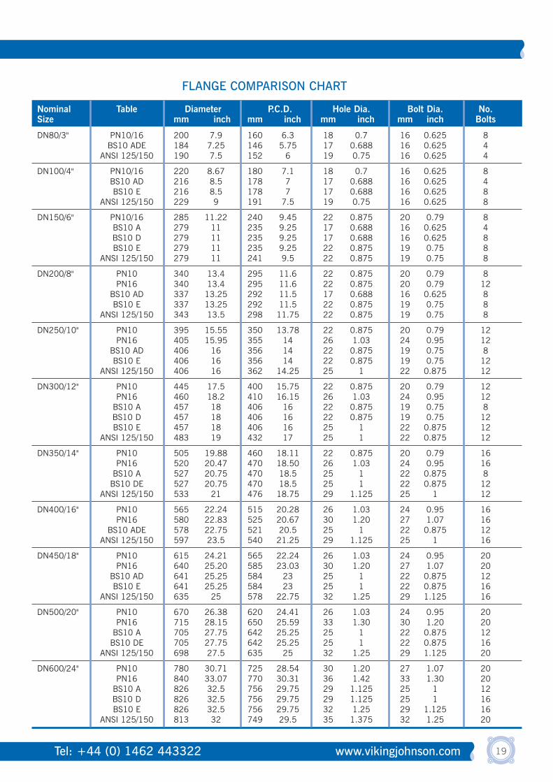
Nominal Table Diameter P.C.D. Hole Dia. Bolt Dia. No.Size mm inch mm inch mm inch mm inch Bolts
DN80/3" PN10/16 200 7.9 160 6.3 18 0.7 16 0.625 8BS10 ADE 184 7.25 146 5.75 17 0.688 16 0.625 4
ANSI 125/150 190 7.5 152 6 19 0.75 16 0.625 4
DN100/4" PN10/16 220 8.67 180 7.1 18 0.7 16 0.625 8BS10 AD 216 8.5 178 7 17 0.688 16 0.625 4BS10 E 216 8.5 178 7 17 0.688 16 0.625 8
ANSI 125/150 229 9 191 7.5 19 0.75 16 0.625 8
DN150/6" PN10/16 285 11.22 240 9.45 22 0.875 20 0.79 8BS10 A 279 11 235 9.25 17 0.688 16 0.625 4BS10 D 279 11 235 9.25 17 0.688 16 0.625 8BS10 E 279 11 235 9.25 22 0.875 19 0.75 8
ANSI 125/150 279 11 241 9.5 22 0.875 19 0.75 8
DN200/8" PN10 340 13.4 295 11.6 22 0.875 20 0.79 8PN16 340 13.4 295 11.6 22 0.875 20 0.79 12
BS10 AD 337 13.25 292 11.5 17 0.688 16 0.625 8BS10 E 337 13.25 292 11.5 22 0.875 19 0.75 8
ANSI 125/150 343 13.5 298 11.75 22 0.875 19 0.75 8
DN250/10" PN10 395 15.55 350 13.78 22 0.875 20 0.79 12PN16 405 15.95 355 14 26 1.03 24 0.95 12
BS10 AD 406 16 356 14 22 0.875 19 0.75 8BS10 E 406 16 356 14 22 0.875 19 0.75 12
ANSI 125/150 406 16 362 14.25 25 1 22 0.875 12
DN300/12" PN10 445 17.5 400 15.75 22 0.875 20 0.79 12PN16 460 18.2 410 16.15 26 1.03 24 0.95 12
BS10 A 457 18 406 16 22 0.875 19 0.75 8BS10 D 457 18 406 16 22 0.875 19 0.75 12BS10 E 457 18 406 16 25 1 22 0.875 12
ANSI 125/150 483 19 432 17 25 1 22 0.875 12
DN350/14" PN10 505 19.88 460 18.11 22 0.875 20 0.79 16PN16 520 20.47 470 18.50 26 1.03 24 0.95 16
BS10 A 527 20.75 470 18.5 25 1 22 0.875 8BS10 DE 527 20.75 470 18.5 25 1 22 0.875 12
ANSI 125/150 533 21 476 18.75 29 1.125 25 1 12
DN400/16" PN10 565 22.24 515 20.28 26 1.03 24 0.95 16PN16 580 22.83 525 20.67 30 1.20 27 1.07 16
BS10 ADE 578 22.75 521 20.5 25 1 22 0.875 12ANSI 125/150 597 23.5 540 21.25 29 1.125 25 1 16
DN450/18" PN10 615 24.21 565 22.24 26 1.03 24 0.95 20PN16 640 25.20 585 23.03 30 1.20 27 1.07 20
BS10 AD 641 25.25 584 23 25 1 22 0.875 12BS10 E 641 25.25 584 23 25 1 22 0.875 16
ANSI 125/150 635 25 578 22.75 32 1.25 29 1.125 16
DN500/20" PN10 670 26.38 620 24.41 26 1.03 24 0.95 20PN16 715 28.15 650 25.59 33 1.30 30 1.20 20
BS10 A 705 27.75 642 25.25 25 1 22 0.875 12BS10 DE 705 27.75 642 25.25 25 1 22 0.875 16
ANSI 125/150 698 27.5 635 25 32 1.25 29 1.125 20
DN600/24" PN10 780 30.71 725 28.54 30 1.20 27 1.07 20PN16 840 33.07 770 30.31 36 1.42 33 1.30 20
BS10 A 826 32.5 756 29.75 29 1.125 25 1 12BS10 D 826 32.5 756 29.75 29 1.125 25 1 16BS10 E 826 32.5 756 29.75 32 1.25 29 1.125 16
ANSI 125/150 813 32 749 29.5 35 1.375 32 1.25 20
FLANGE COMPARISON CHART

20 [email protected] Tel: +44 (0) 1462 443322
The quality and performance of the gaskets is a crucial factor in the efficiency of anycompression-fit pipe joint. It is the gasket which absorbs the forces applied by the expansionand contraction of the pipes, the angular movements and even the weight of the pipe itself.To do this successfully, the gasket must retain its flexibility and compressive stress throughoutits operational life.Viking Johnson gaskets are made in accordance with BS EN 681 for water and BS EN 682for gas, which specifies stringent requirements for physical and chemical properties, aimed atgiving the best possible long-term performance.
QuickFit (fitted) GasketsAll straight couplings, stepped couplings and flange adaptors in sizes up to DN 300/12" in both the Dedicated, MegaFit and MaxiFit (fitted up to DN600/24") products, are normallysupplied ready-assembled with the gaskets already in position. QuickFit gaskets makeassembly of the product quicker and easier.Removal of the gaskets prior to or during assembly of the coupling is neither necessary, nor recommended.
Unfitted GasketsWedge-shaped gaskets are supplied as standard with Dedicated couplings, stepped couplingsand flange adaptors in sizes greater than DN300 (12") nb. Unfitted gaskets are alwaysstretched onto the pipe during installation. For special applications it may be possible tosupply unfitted gaskets in smaller sizes.
Bonded GasketsCertain Viking Johnson products, such as EasiClamp, EasiTee etc, are supplied with waffletype gaskets that are bonded into position. These gaskets are not replaceable.
Gasket Grade SelectionViking Johnson products offer a variety of gasket grades to suit the widest possible range ofapplications. In order to ensure maximum gasket life in the intended application, properselection is essential, See table on page 24.Many factors need to be considered in deciding on the best grade for a specific service.Temperature is the primary consideration, with type and concentration of the product carried,duration and continuity of service also to be considered.Temperatures higher than the maximum quoted for each grade can lead to accelerateddeterioration of the gaskets.
Unless otherwise specified, Viking Johnson couplings are supplied with Grade E (EPDM)gaskets as standard in all sizes. Grade E is suitable for potable water, drainage and sewageapplications but is NOT suitable for use with natural gas, hydrocarbon fuels and lubricants.For gas, oil and fuel applications Grade G (nitrile) should normally be specified.
For Dedicated range only: where special usage conditions apply, eg. special chemicalrequirements, low flammability (eg. in confined spaces such as tunnels) or highertemperature resistance, a range of non-standard gasket materials is available, normally tospecial order. For further information on gasket suitability, contact Viking Johnson.
Standard Gaskets
Introduction
Gasket Types
Gaskets

21Tel: +44 (0) 1462 443322 www.vikingjohnson.com
Grade E - Ethylene Propylene (EPDM)BS EN 681-1 WRAS approved.
Colour flash: GreenTemperature range: -40°C to +90°C (-40°F to 195°F)Suitable for: potable water, sewage, many strong and oxidising
chemicals, some food applications.NOT suitable for: petroleum products, oily compressed air or hydrocarbon
fuels and lubricants.
Grade G - Nitrile (NBR)BS EN 682 Type G.
Colour flash: SilverTemperature range: -20°C to +100°C (-4°F to 212°F)Suitable for: natural gas, petroleum products, low aromatic fuels
(generally <30% aromatic content), oily compressed airand sewage applications.
NOT suitable for: potable water
SPECIALIST GASKETS - AVAILABLE ON REQUEST FOR DEDICATED COUPLING RANGE ONLY
Grade V - PolychloropreneColour flash: YellowTemperature range: -30°C to +90°C (-22°F to 195°F)Suitable for: Good resistance to ageing, weathering, ozone, oxidation,
acids, most inorganic chemicals, vegetable and animal fats. Low flammability.
NOT suitable for: chlorinated hydrocarbons, aromatic solvents.
Grade C - EpichlorhydrinColour flash: White with 'ECO' superimposed.Temperature range: -45°C to +110°C (-50°F to 230°F)Suitable for: petroleum products, including low aromatic fuels
(<30% aromatic content) and oily compressed air.NOT suitable for: Aqueous media.
Grade A - PolyacrylicColour flash: PurpleTemperature range: -10°C to +130°C (15°F to 265°F)Suitable for: Hot transformer and lubricating oils, petroleum products
and low aromatic fuels (<30% aromatic content).NOT suitable for: Water and steam.
Grade O - FluoroelastomerColour flash: BlueTemperature range: -5°C to +180°C (25°F to 350°F)
(+100°C (212°F) on water and steam) Suitable for: Petroleum products, aromatic fuels, hydraulic fluids,
oxidising acids and organic liquids.NOT suitable for: Ketones.
Grade L - SiliconeColour flash: Red gasket materialTemperature range: -60°C to +200°C (-75°F to 395°F) (dry heat),
-60°C to +120°C (-75°F to 250°F) (wet heat)Suitable for: Dry heat conditions, neutral aqueous and some
chemical solutions.NOT suitable for: Petroleum based products or high mechanical
abuse applications.
StorageStored correctly, gaskets maintain full operationalperformance and maximum life expectancy. Pleaseobserve the following storage conditions.• Store in a cool dark place and, where possible,
in black polythene sacks which exclude light,especially ultra-violet.
• Store away from sunlight, electrical dischargesand sparking electric motors.
• Storage temperature should be below 20°C(70°F) and preferably below 15°C (60°F).
• Always store gaskets in an unstressed condition- never hang on hooks, nails, handrails, etc.,even for a short time.
Safety NoteRubber gaskets should never be disposed of byburning, as harmful by-products can be produced.Never handle incinerated or fire damaged gasketswithout proper protective clothing.
LubricationIMPORTANT: It is strongly recommended thatgaskets are well lubricated prior to fitting. Failureto apply lubricant can cause difficulty in fitting andmay result in gasket creep under load. This maycause bolt torques to drop, thus necessitating re-tightening.
Renewal of GasketsIf, for any reason, it becomes necessary to renew a gasket in a Viking Johnson coupling orflange adaptor (where the product cannot be fullydismantled and removed from the pipe), a strip of the correct section gasket material should be cut square about 6mm (0.25") longer than thepipe circumference and inserted into the taperedrecess of the sleeve. Care should be taken that thecut ends of the gasket butt together before bolting up the end rings - glueing the cut ends togetherprior to bolt-up may assist in this. Gasket stripmay be obtained.
NOTE: Reference should be made to the grade ofgasket material required and coupling type.Alternatively, use a gasket of the same cross-section but a larger diameter and cut this squarelyto produce a strip sufficiently long to wrap aroundthe pipe.
Chemical ResistanceThe various gasket grades mentioned in thissection, in addition to having different operatingtemperatures, are resistant to different chemicals.When designing a piping system it is important toverify that the correct gasket grade is specified.
Summary of Gaskets

22 [email protected] Tel: +44 (0) 1462 443322
A number of factory applied coatings are available to ensure full protectionagainst corrosion:
Rilsan Nylon 11Rilsan Nylon 11 is a thermoplastic polyamide powder coating based on vegetable oil. Applied
by dipping in a fluidised bed, it forms a durable protection with excellent resistance to
impact, abrasion, many chemicals and low temperatures. Rilsan Nylon 11 provides all the
corrosion protection you need for the majority of buried and above ground service applications
and eliminates the need for any further protection, such as on-site wrapping. For specific
chemical resistance information, please check the chemical resistance chart at the end of the
section, or ask for specific recommendations.
Rilsan Nylon 11 is WRAS approved, is suitable for use with potable water and has a
maximum operating temperature rating of 90°C (195°F) for water service. Site repair of
localised surface damage, eg. through careless handling, is straightforward using the special
two-pack repair kit.
Most Viking Johnson products are supplied with this protection as standard.
Rilsan Nylon 11 Black is certified to WIS 4-52-01 Part 1 and is the standard Rilsan coating
colour, since this provides the optimum resistance to sunlight exposure during storage.
Fusion Bonded Epoxy (FBE)Many Viking Johnson products may be specified with FBE coating, such as 3M’s Scotchkote
206N. FBE coatings are thermosetting compounds and offer excellent corrosion protection
and resistance to a wide range of organic and inorganic chemicals. Many may be used in
contact with potable water. FBE coatings generally offer good resistance to soil compaction
and cathodic disbondment. Continuous maximum temperature capability of 90°C (195°F) on
water service. Site repair is possible using special repair packs.
GalvanisingA hot dip process giving a zinc coating in conformity with BS.729. Certain Viking Johnson
products may be specified with this coating. Other specialist coatings can be supplied
according to customer requirements.
ShopcoatA primer paint for transit.
Depending on product and market/application, bolts may be coated in the following corrosion-
protection systems:
Sheraplex - low friction compound coating based on sheradising
and fluoropolymer
Galvanised - a metallic zinc coating
Flurene 177 - a low friction coating, mainly used for AquaGrip and
EasiTee products
Stainless steel - bolts may be supplied in either grade 304 or 316 stainless steel
Bolt Coatings
Product Coatings
Corros ion Protect ion

23Tel: +44 (0) 1462 443322 www.vikingjohnson.com
For advice on any chemical not listed here, please contact Viking Johnson for further details
✓ Good Resistance ? Contact Viking Johnson for further advice
CHEMICAL GASKET/ RILSAN SCOTCHKOTECOMPOSITION GRADE
Acetic Acid, up to 10% E,G,V ✓ ✓Acetone E ✓ ✓Acetylene E,G ? ?Air, oil free E, G ✓ ✓Air, oily G, A ✓ ✓Alcohol - butyl, ethyl, methyl E, G ✓ ✓Aluminium Hydroxide E ✓ ?Alums, all types E, G, V ✓ ✓Ammonia Gas, cold E, G, V ✓ ✓Ammonium Bicarbonate E, G ✓ ✓Ammonium Nitrate E, G ✓ ✓Animal Oils/Fats G ✓ ✓Aviation Fuel G, C, O ✓ ✓Benzene O ✓ ✓Blast Furnace Gas O ? ?Bleach Solutions E ✓ ✓Brine E, G, V ✓ ✓Butane Gas G, V ✓ ✓Calcium Chloride E, G, V ✓ ✓Calcium Hydroxide E, G, V ✓ ✓Calcium Hypochlorite (Bleach) E ✓ ✓Carbon Tetrachloride O ? ✓Caustic Soda E, V, G ✓ ✓Chlorine (dry) E ? ?Coke Oven Gas G, O ? ?Copper Sulphate E, G, V ✓ ✓De-ionised Water E, G, V ✓ ✓Detergents E, G, V ✓ ✓Developing Fluids G, V ? ?Diesel Oil G, O ✓ ✓Ethane G ✓ ✓Ethylene G, O ✓ ✓Ethylene Glycol E, G, V ✓ ✓Fuel Oil G, O ✓ ✓Gasoline, Leaded & Unleaded (<30% aromatics) G, O ✓ ✓Glycerine (Glycerol) E, G, V ✓ ✓Glycols E, G, V ✓ ✓Hexane G, O ✓ ✓
CHEMICAL GASKET/ RILSAN SCOTCHKOTECOMPOSITION GRADE
Hydrochloric Acid, Cold to 50% E, O ? ✓Hydrogen, Gas E, G, V ✓ ✓Hydrogen Sulphide E, V ✓ ✓Kerosene G, A, O ✓ ✓Ketones E ✓ ✓Lubricating Oil, Refined G, O ✓ ✓Methane G, A, O ✓ ✓Methyl Ethyl Ketone E ✓ ✓Mineral Oils G ✓ ✓Naphtha O ✓ ✓Natural Gas G, C, O ✓ ✓Nitric Acid, to 10% E ? ✓Nitrogen E, G, V ✓ ✓Oil, Crude Sour G, O ✓ ✓Oxygen E ✓ ✓Ozone E ✓ ✓Petroleum Oils G, O ✓ ✓Phenol (Carbolic Acid) O ✓ ✓Polyvinyl Acetate E ✓ ✓Potassium Chloride E, G, V ✓ ✓Potassium Hydroxide E, V ✓ ✓Potassium Permanganate G ? ?Propane Gas T ✓ ✓Sewage E, G, V ✓ ✓Sodium Bicarbonate E, G, V ✓ ✓Sodium Carbonate E ✓ ✓Sodium Chloride E, G, V ✓ ✓Sodium Hydroxide, to 50% E, V ✓ ✓Sodium Hypochlorite, to 20% E, G ✓ ✓Styrene O ✓ ?Sulphuric Acid, to 25%, 66°C (150°F) E ✓(10%) ✓Toluene O ✓ ✓Turpentine G ✓ ✓Vegetable Oils E, G ✓ ✓Vinyl Acetate E ? ?Vinyl Chloride O ? ?Water, to 90°C (195°F) E ✓ ✓Water, Potable E ✓ ✓Water - Waste, Seawater E, G, V ✓ ✓White Spirit G ✓ ✓
CHEMICAL RESISTANCE CHART

24 [email protected] Tel: +44 (0) 1462 443322
Internationally recognised as one of the most reliable methods of joining plain-ended pipes, the Viking Johnson systemconsists of a wide range of couplings, flange adaptors, repair clamps and special products to suit almost any application.
The V ik ing Johnson Product Range
MaxiFitStraight and stepped couplings, flange adaptors, end caps and specialthreaded combinations, each with a wide pipe diameter range. Used forjoining pipes of the same or different materials and nominal bores, or forjoining pipes to flanges in a variety of drillings. Now available in sizesfrom DN40 (1.5") to DN600 (24") nominal bore and to suit an outsidediameter range up to 25.5mm (1") in a single straight coupling. Particularly intended for the repair, modification and maintenance ofpipework systems, the MaxiFit product range permits greatly reducedstockholding, improved usability and reduced overall costs. All MaxiFit products have a working pressure rating of 16 bar (230psi)(10 bar for products with PN10 flanges)
Dedicated Viking Johnson RangeJoins pipes of specified outside diameter. Tailored to your particularneeds. Whatever the diameter and pressure, the Viking JohnsonDedicated Coupling range can be made to suit. Available in sizes fromDN40 (1.5") to larger than DN5000 (200"), and from vacuumapplication to pressures of more than 100 bar/1500 psi (according to size).The Straight Coupling - joins pipes of the same outside diameter.The Stepped Coupling - joins pipes of differing outside diameters and/or different pipe materials.The Flange Adaptor - to connect flanged pipe, or any flanged fitting, to plain-ended pipe.
FlexLockA unique self-anchoring range of couplings and flange adaptors, suitablefor use on steel and ductile iron pipes. Fully end-load bearing forworking pressures up to 16 bar (230psi) (up to DN200) and 10 bar (145psi) (DN250).
Dismantling JointsThe Viking Johnson Dismantling Joint DN50 to DN2000+ providesa simple and effective method for connection and removal of valvesand other equipment in flanged pipework. A Dismantling Joint consists of a flange adaptorand a flanged spigot pipe, together with
a number of tie rods.It is essentially a double flangedpipe of adjustable length which, when bolted to the adjacent pipework, provides rigidityin the system, yet permits removal of valves, etc., without major pipework dismantling.
UltraGripHigh tolerance couplings, flange adaptors and end caps DN50 - DN300with end restraint, which can be easily converted to allow pipeexpansion. Supplied fully assembled, complete with gripping inserts that work on most types of pipe. Used as a gripping product below ground it avoidsthe need for concrete thrust blocks.
25Tel: +44 (0) 1462 443322 www.vikingjohnson.com
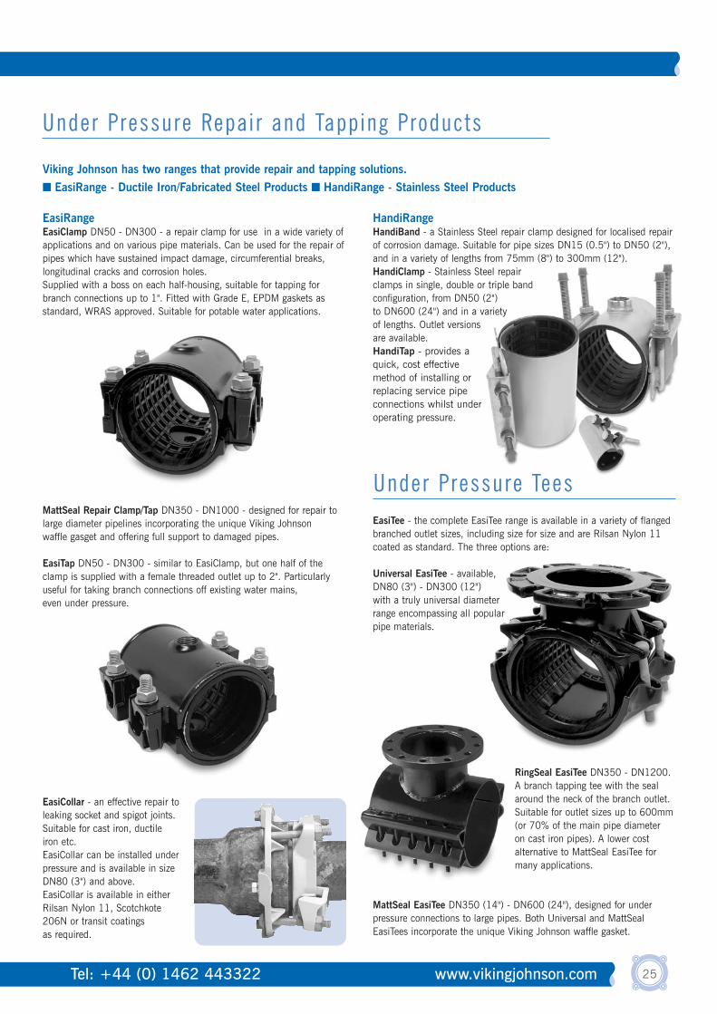
Viking Johnson has two ranges that provide repair and tapping solutions.■ EasiRange - Ductile Iron/Fabricated Steel Products ■ HandiRange - Stainless Steel Products
Under Pressure Repai r and Tapping Products
EasiRangeEasiClamp DN50 - DN300 - a repair clamp for use in a wide variety ofapplications and on various pipe materials. Can be used for the repair ofpipes which have sustained impact damage, circumferential breaks,longitudinal cracks and corrosion holes. Supplied with a boss on each half-housing, suitable for tapping forbranch connections up to 1". Fitted with Grade E, EPDM gaskets asstandard, WRAS approved. Suitable for potable water applications.
MattSeal Repair Clamp/Tap DN350 - DN1000 - designed for repair tolarge diameter pipelines incorporating the unique Viking Johnsonwaffle gasget and offering full support to damaged pipes.
EasiTap DN50 - DN300 - similar to EasiClamp, but one half of the clamp is supplied with a female threaded outlet up to 2". Particularlyuseful for taking branch connections off existing water mains, even under pressure.
EasiCollar - an effective repair toleaking socket and spigot joints.Suitable for cast iron, ductile iron etc.EasiCollar can be installed underpressure and is available in sizeDN80 (3") and above. EasiCollar is available in eitherRilsan Nylon 11, Scotchkote206N or transit coatingsas required.
HandiRangeHandiBand - a Stainless Steel repair clamp designed for localised repairof corrosion damage. Suitable for pipe sizes DN15 (0.5") to DN50 (2"),and in a variety of lengths from 75mm (8") to 300mm (12"). HandiClamp - Stainless Steel repairclamps in single, double or triple bandconfiguration, from DN50 (2")to DN600 (24") and in a varietyof lengths. Outlet versionsare available.HandiTap - provides a quick, cost effective method of installing or replacing service pipe connections whilst under operating pressure.
EasiTee - the complete EasiTee range is available in a variety of flangedbranched outlet sizes, including size for size and are Rilsan Nylon 11coated as standard. The three options are:
Universal EasiTee - available,DN80 (3") - DN300 (12") with a truly universal diameter range encompassing all popular pipe materials.
RingSeal EasiTee DN350 - DN1200. A branch tapping tee with the sealaround the neck of the branch outlet.Suitable for outlet sizes up to 600mm(or 70% of the main pipe diameteron cast iron pipes). A lower costalternative to MattSeal EasiTee formany applications.
MattSeal EasiTee DN350 (14") - DN600 (24"), designed for underpressure connections to large pipes. Both Universal and MattSealEasiTees incorporate the unique Viking Johnson waffle gasket.
Under Pressure Tees
26 [email protected] Tel: +44 (0) 1462 443322
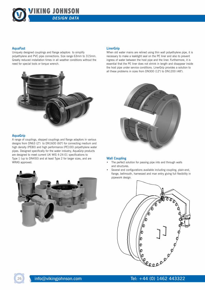
AquaFastUniquely designed couplings and flange adaptors to simplifypolyethylene and PVC pipe connections. Size range 63mm to 315mm.Greatly reduced installation times in all weather conditions without theneed for special tools or torque wrench.
AquaGripA range of couplings, stepped couplings and flange adaptors in variousdesigns from DN63 (2") to DN1600 (60") for connecting medium andhigh density (PE80) and high performance (PE100) polyethylene waterpipes. Designed specifically for the water industry, AquaGrip productsare designed to meet current UK WIS 4-24-01 specifications to Type 1 (up to DN450) and at least Type 2 for larger sizes, and areWRAS approved.
AquaGripA range of couplings, stepped couplings and flange adaptors in variousdesigns from DN63 (2") to DN1600 (60") for connecting medium andhigh density (PE80) and high performance (PE100) polyethylene waterpipes. Designed specifically for the water industry, AquaGrip productsare designed to meet current UK WIS 4-24-01 specifications to Type 1 (up to DN450) and at least Type 2 for larger sizes, and areWRAS approved.
LinerGripWhen old water mains are relined using thin wall polyethylene pipe, it isnecessary to make a leaktight seal on the PE liner and also to preventingress of water between the host pipe and the liner. Furthermore, it isessential that the PE liner does not shrink in length and disappear insidethe host pipe under service conditions. LinerGrip provides a solution toall these problems in sizes from DN300 (12") to DN1200 (48").
LinerGripWhen old water mains are relined using thin wall polyethylene pipe, it isnecessary to make a leaktight seal on the PE liner and also to preventingress of water between the host pipe and the liner. Furthermore, it isessential that the PE liner does not shrink in length and disappear insidethe host pipe under service conditions. LinerGrip provides a solution toall these problems in sizes from DN300 (12") to DN1200 (48").
Wall Coupling• The perfect solution for passing pipe into and through walls
and structures.• Several end configurations available including coupling, plain-end,
flange, bellmouth, harnessed and man entry giving full flexibility in pipework design.

PIPE MATERIALPE PipeMaterials
BarrierPipesRigid Pipe Materials
VIKING JOHNSONPRODUCT RANGE
Cast
Iron
Duct
ile Ir
onSt
eel
Thin
walled
/True
bore
Stainl
ess St
eelAs
best
os C
emen
tCo
ncre
teCl
ayAB
SLe
adCo
pper
PVC-
U/M
etric
PVC
GRP
HEP3
0Po
lypro
pylen
eM
DPE/
PE80
HDPE
/PE1
00Pr
otec
t-a-li
nePu
riton
27Tel: +44 (0) 1462 443322 www.vikingjohnson.com
PRODUCT RANGE
40 - 600(A) MaxiFit Range
Size Range (mm)Coupling
40 - 600Flange Adaptor40 - 600Step Coupling40 - 300
(A) Dedicated Range(QuickFit)
Coupling40 - 300Flange Adaptor40 - 300Step Coupling
50 - 300(A) MegaFit Range
Coupling50 - 300Flange Adaptor50 - 300Step Coupling63 - 180
AquaGrip Range
Coupling63 - 180Transitional63 - 180Flange Adaptor225 - 800Flange Adaptor900 and greaterFlange Adaptor63 - 315Coupling63 - 315
AquaFast RangeFlange Adaptor
50 - 600
(A) EasiRange
Repair Clamp80 - 300Universal EasiTee350 - 600Matt Seal EasiTee350 - 1200Ring Seal EasiTee50 - 150Euro Repair Clamp80 - 1200Collar15 - 50
HandiRangeRepair Band
50 - 600Repair Clamp
50 - 300
(A) UltraGrip Range
Coupling50 - 300Flange Adaptor50 - 300Reducers50 - 300End Caps50 - 250
FlexLock RangeCoupling
50 - 250Flange Adaptor
300 and greaterDedicated Range
(Unfitted)
Coupling300 and greaterFlange Adaptor300 and greaterStep Coupling
✓ ✓ ✓ ✓ 1 ✓ ✓ ✓ ✓ ✓ ✓✓ ✓ ✓ ✓ 1 ✓ ✓ ✓ ✓ ✓ ✓✓ ✓ ✓ ✓ 1 ✓ ✓ ✓ ✓ ✓ ✓✓ ✓ ✓ ✓ 1 ✓ ✓ ✓ ✓ ✓✓ ✓ ✓ ✓ 1 ✓ ✓ ✓ ✓ ✓✓ ✓ ✓ ✓ 1 ✓ ✓ ✓ ✓ ✓✓ ✓ ✓ ✓ 1 ✓ ✓ ✓ ✓ ✓✓ ✓ ✓ ✓ 1 ✓ ✓ ✓ ✓ ✓✓ ✓ ✓ ✓ 1 ✓ ✓ ✓ ✓ ✓✓ ✓ ✓ ✓ 1 ✓ ✓ ✓ ✓ ✓✓ ✓ ✓ ✓ 1 ✓ ✓ ✓ ✓ ✓✓ ✓ ✓ ✓ 1 ✓ ✓ ✓ ✓ ✓
✓ ✓ ✓✓ ✓ ✓✓ ✓ ✓
✓ ✓✓ ✓
✓ ✓ ✓ ✓ ✓✓ ✓ ✓ ✓ ✓
✓ ✓ ✓ 6 5 5 5✓ ✓ ✓✓ ✓ ✓✓ ✓ ✓✓ ✓ ✓ ✓ 4 4 4 4✓ ✓ ✓ ✓ ✓
✓ ✓ ✓ ✓ ✓✓ ✓ ✓ ✓ ✓ ✓ ✓ ✓ ✓ ✓ ✓ ✓ ✓ ✓ ✓ ✓✓ ✓ ✓ 2 ✓ 2 ✓ 3 3 3✓ ✓ ✓ 2 ✓ 2 ✓ 3 3 3✓ ✓ ✓ 2 ✓ 2 ✓ 3 3 3✓ ✓ ✓ 2 ✓ 2 ✓ 3 3 3
✓ ✓✓ ✓
This table defines the suitability of Viking Johnson products for a range of pipe materials.
Suitability of the Viking Johnson product range is to be checked by usingthe additional product literature.
Note: A Viking Johnson product is suitable upto a stated working pressure rating for a given pipe material(A) Pipe material is suitable within Viking Johnson product OD tolerance range. (1) Please contact Viking Johnson Marketing department for further details. (2) Only as Flex Version.(3) Only as Gripping version. (4) Available upto DN150. (5) Available upto DN200. (6) Available upto DN300.


29Tel: +44 (0) 1462 443322 www.vikingjohnson.com
Notes
30 Tel: +44 (0) 1462 443322

46-48 Wilbury WayHitchin HertfordshireSG4 0UDUnited Kingdom
Tel: +44 (0)1462 443322Fax: +44 (0)1462 443311
email: [email protected]
For further information on all Viking Johnson products and services contact our Marketing Department.
ISO 9001 ISO 14001