deighta.com · web viewthe present invention generally relates to a portable fluid heating device...
TRANSCRIPT

U.S. PATENT DOCUMENT
PROVISIONAL PATENT DRAFTCopyright ©by Dale G. Basgall 2012
Saturday, March 24, 2012
TITLE :
FLUID HEATER THAT IS LIGHTWEIGHT AND PORTABLE FOR PEOPLE LIVING IN GEOGRAPHICALLY REMOTE LOCATIONS USING MOBILE DC ELECTRICITY FOR POWER.
INVENTOR(S) NAME: DALE G. BASGALL
Current contact address: 2580 Hana Highway, Hana Hawaii 96713
SMALL ENTITY:
Roy Smith, Lui Dussen, Joshua Smith, Randy Wuller
URL: https://deighta.com aka Dale G. Basgall, all rights reserved.
e-mail: [email protected]
1
BACKGROUND OF THE INVENTION
Field of the Invention:
The present invention generally relates to a portable fluid heating device for producing heated water when in a mobile setting and is more particularly concerned with providing a method for taking a warm shower or for making a hot beverage in a situation where there is no AC electricity power supply available and, is the primary purpose of the present invention Dolphin 5. Conditions may exist where there is no pressurized clean water to heat, however, some standing water like in a pond or creek or other drinkable fluid could be available for boiling, cooking, and showering. The present invention Dolphin 5 heats fluid quickly from the usage of a DC storage battery accessible to almost anyone anywhere and can be found in any geographically remote location. The product Dolphin 5 of the present invention operates in a totally mobile environment whereas people that are mobile could potentially have access to many types of batteries. The present invention provides heated fluids in adverse conditions anywhere a battery is available.
2
Description of the Prior Art:
Many individuals that are employed by the U.S. military and particularly the U.S. ARMY may find themselves in situations lacking clean hot water and needing a shower or a hot cup of coffee. The product of the present invention (Dolphin 5) is intended for this type of person that does not have the option to plug something into an AC electrical supply outlet nor has the option to generate their own electricity and develop electrical noise from the process or smoke from a chemical or wood heating method. This type of person could be very limited on time available to get warm and hot water on demand for cleaning purposes. Other individuals that have elected to be out in the wilderness such as hunters and campers could also find application with the present invention as well as individuals in an emergency situation without AC electricity. This AC electricity cannot be stored unless it is rectified into DC power to be stored in batteries. Also the generation of AC power on location produces an electromagnetic signature that is detectable with inexpensive measurement meters of which the DC heaters do not produce that type of electromagnetic radiation noise and commonly referred to as RFI (radio frequency interference) or EMR (electromagnetic radiation).
3

There are several methods for producing hot water for purification purposes , some require AC electricity and are very bulky and not intended for mobile use. If there is no AC electricity available those water heaters will not function. Other methods of producing hot water require volumes of water to be stored and for example 50 U.S. gallons which is approximately 400lbs. in weight. These large storage tanks require a longer time to warm up and they are directed mostly to heating large volumes of water. There are other on demand water heating methods such as the Paloma model which is designed for the purpose of hot water on demand and there is no storage tank available for hot water. These systems require a gas bottle like propane to operate and are mostly all connected to a water source like a line or hose which is pressurized within sealed pipes. These systems usually mount onto a wall and require hoses to be hooked up to the water supply as well as outlet hot water tubes, and furthermore the gas supply bottle requires the use of a wrench. There are also portable versions of the gas operated Paloma's for the sole purpose of showering but require a supply of water thru a hose or water line and a pressurized gas tank. Also most all prior art referenced uses a method of heating water as it flows through the heat exchanger elements and to the end user and is using energy to heat fresh cool water or fluid as it enters and flows through the heaters portion of the prior art referenced.
4

While those systems of heating water are widely used in geographically isolated locations and perform very well, there are several drawbacks while using any one of those products and methods for producing hot water. One advantageous factor of using one of the portable Paloma’s is that no electricity is needed but an ignition source, such as a lighter flame is. An AC power source for heating water is not an option in this particular scenario. The previous methods of heating water all require a clean water supply that is forced through the heater from an inlet hose or pipe. In addition a tank of gas is required with wrenches to hook the water and gas fittings onto and are not intended for mobile applications in the sense of fleeting mobility in a timely fashion.
Consequently, a need exists for a battery powered stand alone water heater requiring no hoses or hookups for a gas bottle or wrenches to operate. In addition, the methods requiring a water supply hose or pipe to force the water through the heaters core and that allow them to produce the flow of the heated fluid, are all vulnerable to problems associated with a natural disaster affecting water systems. Future advancements in emergency water heater designs will need to include DC power, coupled with the ability to supply pressurized hot water without being connected to a pressurized main water line to make them function for the production of hot fluid quickly on demand.
5
SUMMARY OF THE INVENTION
The present invention Dolphin 5 provides a “stand alone portable” water heater designed to satisfy the aforementioned needs. Hot water is produced by cooling a metal block submerged in water. The metal block is heated by a polar array of DC heating elements that are displaced in a radial formation from the block center bore. The DC heating elements are individually energized and separately positioned to achieve a temperature differential in the hot fluid outlet product flow path. This allows for blending of warm and hot fluids together to achieve the optimum temperature needed for usability and end user satisfaction. Furthermore the present invention DOLPHIN 5 does not need to have a line or hose attached that provides a clean flow of water into the water heater. The present invention solves that problem by the heater assembly being submerged in the fluid and the outer container pressurized with air. Furthermore this method for producing hot fluids on demand using a submerged heating element within a confined vessel or chamber while preventing continued cool water flow inward is a more efficient method for the conservation of the required energy input and fluid volume.
6
A containment bucket that holds 5 U.S. gallons of fluid is filled and the product of the present invention Dolphin 5 is partially submerged into the fluid to be heated. The lids are buckled onto the top & bottom portion of the container that retains the liquid capacity to be heated. The container is sealed airtight after the buckles on the roof and floor are clamped into their respective lock positions. The sealed container has flow check valves that provide a means to pressurize the inside area of the container housing the Dolphin 5 product of the present invention. The product Dolphin 5 remains submerged within the pressurized fluid. This method allows 5 gallons of fluid to be scooped from the source of the fluid with no pressure involved, and the fluid is dumped into the container housing Dolphin 5. After the fluid is in and the roof and floor are buckled in place and the container is sealed airtight, a mechanical apparatus operated by a person then pressurizes the internal area that is not occupied by the fluid within the container, the porting within the coolant passages allows fluid to flow from one selected variable flow valve from the exit port at the exit of the containerhousing Dolphin 5. Cool drinking water for example from one port, and out of thecenter outlet port the warm water can flow for showering as soon as the temperature valving opens the inner cooling tube as the temperature reaches a preset temperature set mechanically by the end user. Pressurized flow of hot fluid for beverages is also available from the product of the present invention Dolphin 5 until the fluid is dispensed .
7
This allows the end user three choices of water temperatures simultaneously and a means to blend them together. The present invention Dolphin 5 also uses the conventional pressurized inlet flow method as an option for the user.
Furthermore the product of the present invention Dolphin 5 solves another problem of the prior art designs. This problem solved is mobility and the entire product Dolphin 5 fits in one container 16”W x 16”W x 21” L. The weight without water is easily transported by one person, and is stackable both physically for storage and cascaded matrixes together to make one large water heater. The water heater is intended to be used when the AC power grid goes out in an emergency situation caused by any unforeseen tragedy. The product of the present invention utilizes source power from any readily available DC battery from mobile equipment. There are millions of these batteries available to the general public and the DC power is stored energy, which solves the problem of finding a power source in an emergency situation like for example grid power AC after a national disaster renders people in those situations helpless without alternative potential to heat water for cleaning or for a hot beverage. The present invention uses common battery cables found in any auto parts store for supplying the DC power potential to heat the fluids.
8

In fact the intended operation of the present invention Dolphin 5 can be accomplished by purchasing an inexpensive quick start auto battery/air compressor from Costco or Wal-Mart and this solves a major supply issue for powering the Dolphin 5 and provides many choices for the end user for inexpensive power supplies. The product of the present invention requires a DC battery to operate.
Accordingly, the present invention relates to an article of manufacture and a method to produce heated water on demand from a pool of liquid, and does not rely on a pressurized flow from external lines or pipes to produce hot water flow out to the end user as a final product, which includes the operative steps of : (a) to produce heat by DC current flow and exchange it conductively into a metal block (mass) submerged in cool fluid ; and (b) exchange that heat from the metal block conductively into a centralized inner cooling tube and two additional polar arrays of outward cooling tubes and the hot fluid continuing thru to the exiting hot fluid restrictor valve ; and (c) allow fluid to flow thru the heat exchanger by the application of gas pressure onto an area of exposed water surface sealed airtight within the present inventions container housing.
9
More specifically, the pressure of gas can be very low and a mechanical human method of producing compressed air is sufficient for proper operation of the product invention Dolphin 5, and in fact an example would be a small bicycle tire pump as sufficient to supply pressurized air for proper operation; and (d) to provide several temperature gradients of heated fluid simultaneously by blending together within the porting of the inlet and outlet distribution blocks of the present invention Dolphin 5.
BRIEF DESCRIPTION OF THE DRAWINGSFIG. 2 is a schematical side elevational view of a preferred embodiment of the present invention Dolphin 5.
FIG. 3 is a side elevational view of a preferred embodiment of the fluid heater of the present invention.
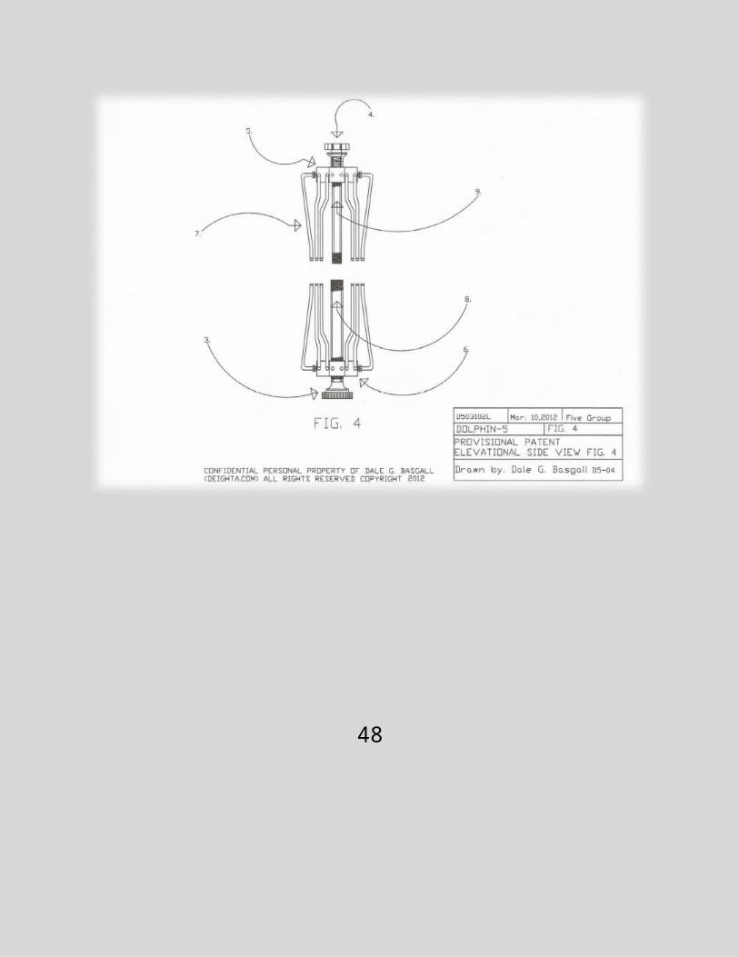
FIG. 4 is a side elevational view of elements 3. & 4. the Inlet and Outlet Bells of the present invention.
10
FIG. 5 is a side elevational view of elements 5. & 6. the Fluid Distribution Manifolds of the present invention.
FIG. 6 is a side elevational view of elements 7.Outer Cooling Tubes of the present invention & 8. & 9. Inner Cooling Tubes.
FIG. 7 is a side elevational view of items 8. & 9. These are two pipes referred to as the Inner Cooling Tube (inlet 8. exit 9.).
FIG. 8 is an end elevational view of looking through the container and the heat exchanger block mountings for DOLPHIN 5.
FIG. 9 is an open end elevational view of a preferred embodiment of the heat generating mechanism of the fluid heater apparatus.
FIG. 10 is a side & end elevational view of a preferred embodiment of the thermal heat conduction element.
11

FIG. 11 is a face end elevational view of a preferred embodiment of a quadrant element dissected from the thermal conduction element.
FIG. 12 is an elevational face end view of an assembly of two singular quadrant elements as twins.
FIG. 13 is a face & side elevational view of the spacer plate that is optional for the assembly of the quadrants of (2.)
FIG. 14 is a schematical outlet end elevational view of a preferred embodiment of the fluid heating device.
FIG. 15 is an inlet end elevational view of a preferred embodiment of the present fluid heating device.
FIG. 16 is an outlet and inlet face elevational view of preferred embodiments of the present fluid heating device.
12
FIG. 17 is a side elevational view of the 3 metal blocks 2., 5., & 6. assembled into a 5” x 5” cube.
FIG. 18 is a schematical side elevational view of the fluid flow paths of the present invention fluid heater.
FIG. 19 is a schematical elevational view of elements and parts of the present invention fluid heater kit & package dimensions.
FIG. 20 is a detailed description of the raw materials required to make one of the present invention DOLPHIN 5.
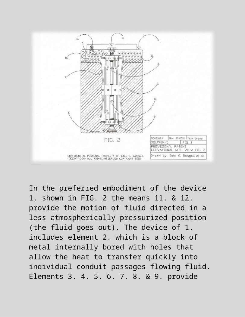
DESCRIPTION OF THE PREFERRED EMBODIMENTSReferring now to the drawings, and more particularly, to FIG. 2 there is a fluid heater named DOLPHIN 5, and generally designated 1. within the preferred embodiment for producing heated fluid on demand using mobile DC electricity to power the device heater. The device 1. basically includes means 10.11.&12. which are water, air, and pressure for producing fluid to flow outward of the device. In addition DC electricity is needed to power the DC thermal heating elements positioned within a heat exchanger block 2. for heating the fluid.
13
In the preferred embodiment of the device 1. shown in FIG. 2 the means 11. & 12. provide the motion of fluid directed in a less atmospherically pressurized position (the fluid goes out). The device of 1. includes element 2. which is a block of metal internally bored with holes that allow the heat to transfer quickly into individual conduit passages flowing fluid. Elements 3. 4. 5. 6. 7. 8. & 9. provide confined flow paths of fluid to and from the element 2. (Heat Exchanger Block).
14
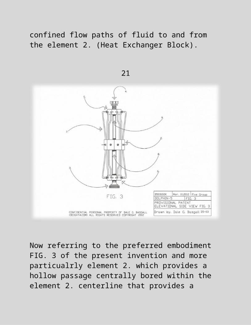
Now referring to the preferred embodiment FIG. 3 of the present invention and more particualrly element 2. which provides a hollow passage centrally bored within the element 2. centerline that provides a confined pathway for fluid to flow from 6. metal block (Inlet Distribution Manifold) center hollow bore through the 2. metal block (Heat Exchanger) center hollow bore (inlet). From the hollow center bore outlet of 2. inlet fluid is provided a pathway into another hollow bore centrally located within the third metal block 5. (Outlet Distribution Manifold).
15

Within the centerpoint of the inlet distribution manifold 6. faces there is a hollow passage bored to allow fluid to pass through and into tube 8. (Inlet Inner Cooling Tube). As the fluid flows within it’s confined barriers (hollow passages) and through to the inlet face end of the heat exchanger block center hollow passage, the fluid is blocked at the outlet of the cooling fluid hollow passage centrally located and bored into all three metal blocks comprising the present invention. This cooling fluid remains blocked at the outlet face end of the heat exchanger block of 2.until a temperature sensitive restrictor valve reaches the preset center coolant temperature and then begins to open the center cooling circuit of the present invention. Heated fluid is then opened into 9. (Outlet Distribution Manifold) center hollow bore and is again restricted by another temperature sensitive restrictor valve until the valve opens the center cooling passage into 4. (Outlet Bell) center cooling fluid heated water passage and further out to the end user as the final product, “heated fluid”. The preferred embodiments of FIG(s). 2. & 3. recite same that the present invention has 5 essential elements 2. heat exchanger block, 3. Inlet Bell, 4. Outlet Bell, 5. Outlet Distribution Manifold, and 6. the Inlet Distribution Manifold which all as assembled provide the art of the present invention. Insubstantial are 7. Outer Cooling Tubes, 8. Inlet Inner Cooling Tube and 9. Outlet Inner Cooling Tube.
16
Referring now to the preferred embodiment of FIG. 9 and within the preferred embodiment one end face view of heat exchanger 2. shows a definitive geometry encompasing the arrays of heat exchanger cooling ports, and the method of exchanging thermal heat energy into fluid quickly. Retention of 2. the heat exchanger block within the housing 1. of the present invention shows simply the elements used in this application of the present invention fluid heater. Element 14. is an elongated hollow tube and 13. are two threaded nuts, locking them into position and in this application defined as mounting tube nut.
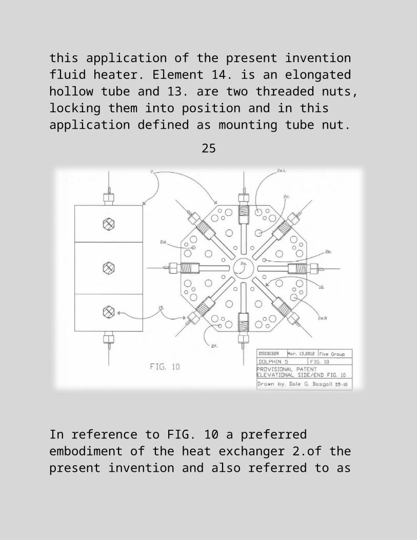
17

In reference to FIG. 10 a preferred embodiment of the heat exchanger 2.of the present invention and also referred to as the “metal block thermal conduction element” and operates exclusively by design only. This design forms geometry of symmetry for the usage of multiple heating elements 15.defined to produce heat when electricity is applied, and to exchange the thermal energy quickly into multiple fluid paths simultaneously heating causing the slower moving fluid in smaller passages to heat quicker and be hotter upon exit of the fluid heater of the present invention.
18
Furthermore, and in specific element 2.of FIG. 10 shows the pattern of cooling passage hollow bores and their placement within circular paths. The bore centers of the outward polar arrays displaced are based on a specific radius distance from the centermost point a, within and thru either end face of the heat exchanger 2. These circular path bores are noted b, c, d, e, f, called cooling bands whereas the centermost bore thru a, allows cooling fluid to pass in a higher volume and at a lower temperature than the polar arrays in another cooling band farther out from the a, centerline axis. There is definition noted as to the direction of travel of the fluid to be heated through the present invention and considered to be a unidirectional device for proper operation as intended by the inventor. Inner Cooling path 2a. denotes the center bore hollow passage that flows coolant water through to the outlet side of the heat exchanger block 2. of the present invention. Coolant passage (bore thru hollow) 2a. is located in the face ends and through to each other forming one confined passage for the inner coolant to flow. There is no defined direction of the fluid flowing within the heat exchanger block until the present invention fluid heater is assembled as a working product. Displaced outward in a polar array from centerline 2a.are 8 bores band b. and noted as band 2b. Further outward from centerline 2a.are bands 2c.2d.2e.2f.all forming circular arrays with specific functions in regards to the performance of the heat exchanger block 2.of the present invention fluid heater.
19
The symmetry of the heat exchanger block 2.in whole of the present invention allows more thermal heat to exchange quicker from the glow plugs 15. (heaters) into the polar arrays of cooling passage bores by the application of heat onto multiple smaller fluid conduits of faster moving fluid than passage 2a. The hot element rod 16.of the present invention is the centralized heated point from electric power application to the glow plug(s) 15.The cooling fluid is forced to flow into the center inlet 2a. bore of the inner cooling passage of the heat exchanger block 2.
20
Referring now to the preferred embodiment of FIG. 11 and more paticularly concerned with 17. which is a quadrant element dissected from the heat exchanger 2. of the present invention. This becomes important for downsizing into singular quadrants that has been seperated from an already existing element as in a fractal portion of element 2. Referring now to heating rod 16. of FIG. 11 the preferred embodiment of 17. used in specific to point out the projected heat paths and thermal gradients of heated fluid out as an end product of the present invention Dolphin 5. 2a, is the inner cooling passage and is bored though from one face end and out the other which carries a larger volume than any of the other cooling bore passages for the flow conduit of heated fluid through the heat exchanger 2. 2c. and 2e. are also passages that allow fluid to flow through and are identical to the bore patterns desribed as placed in bands from the centerline 2a. 2eL. and 2eR. indicate a position relative the centerline as positioned in the FIG.11 as 17. and L indicates left of centerline and R to the right and is moreover refernced for specifically indicating seperation lines within the circumferal symmetry of the heat exchanger 2. of the present invention fluid heater. 16. is the heating rod and the arc line indicating it in the FIG. 11 is at it center radient point and eminates heat outward in a radial pattern of heat dissipation and thermal heat is generated and flows outward first to the cooler areas and primarily affects 2b. first and the circumferal area is smaller compared to outward band areas.
21
The thermal heat further dissipates into 2a. and 2c and finally into the d, e, and f, bands of hollow bores though the face ends of 17. which is one of the 4 quadrant fractal element cubes that can be seperated from the heat exchanger 2. of the present invention fluid heater and used as singular elements in a portable kit form.
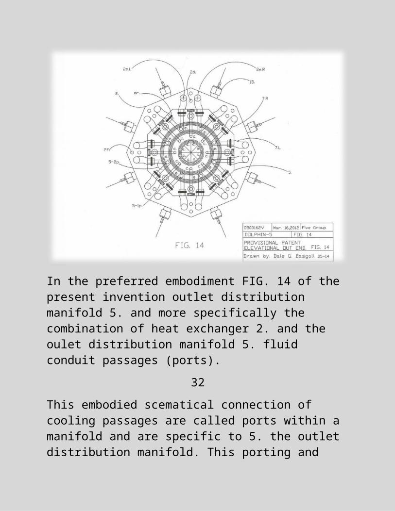
In the preferred embodiment FIG. 14 of the present invention outlet distribution manifold 5. and more specifically the combination of heat exchanger 2. and the oulet distribution manifold 5. fluid conduit passages (ports).
22

This embodied scematical connection of cooling passages are called ports within a manifold and are specific to 5. the outlet distribution manifold. This porting and resistance to fluid flow is critical for the proper functioning of the present invention. The outlet distribution manifold could also be considered a collector of heated fluid from three bands of cooling passages which are indicated by a, c, and e. 5-2p. indicates two ports adjoin within the metal block of element 5. the outlet distribution manifold, and correspond with the cooling band arrays of 2. the heat exchanger of the present invention. Cooling tubes 7R. and 7L. are separate passages from the flow of heated fluid exiting from the heat exchanger 2d. outlet cooling ports,in addition c band cooling port array is also separate from the fluid flow within (a), the inner coolant passage outlet. This method produces preferred temperature outlet fluid for the benefit of the end user in satisfying their application of a heated fluid. Referring back to FIG. 14 the preffered schematical embodiment shows 2eR. which is the exit side port bore and innerconnected with the outlet distribution manifold 5. through an external counduit for confined fluid flow further referenced as 7R. and indicated based upon an outlet face view of the fluid heater of the present invention. There are 16 e band ports bored within heat exchanger 2. and all points on the outer circumference of the heat exchanger reference a centerline inward.
23

A more detailed clarification on positioning is carried out by looking inward at the outlet face of heat exchanger 2. of FIG. 14 and referencing the overlay of the outlet distribution manifold most outward face. In a frame of reference the outward face of 5. is rotated 22.5 degrees in relation to the face of 2. and this provides for the compact design of the three metal blocks of the present invention.
24
Referring now to FIG. 15 ia a preferred embodiment of the present fluid heating elements and is a scematical inlet face end view which now the only points to make on the porting is they are looked at as reversed in reference to the preferred embodiments of FIG. 14. All have the same function as previously mentioned however inlet distribution manifold 6. as viewed in FIG. 15 shows the porting configuration as the three bands a, c, and e are all combined and adjoined as one.
Referring back now to FIG.2 and the product 1. of the present invention and more specifically referring to the diagonal lines within the container of 1. and those are specifiying a fluid and in this case it is water standing (in a reservoir). The reservoir is sealed airtight in this pictorial side view of the schematical product of the present invention fluid heater. Submerged under the fluid is inlet bell 3. that is removably attached and provides an open passage for water to flow into the inlet end of inlet distribution manifold 6. and continues until it is blocked at the inlet of the cooling tube 9. At this point the water level equalizes with the water level sealed airtight within the present inventiot fluid heater container and fills porting passages c, and e to the fluid level sealed within the container. Air is injected into the container at 12. the gas inlet check valve and translates it’s force onto the water surface exposed to it and referenced by 10. within FIG. 2.
25
This forces fluid into the inlet bell 3. at the amplified pressure of gas pressure within the container and exposing a specific area of the surface of the water which is a multiple effect resulting a pressure in at inlet bell 3. All cooling ports are blocked at the outlet bell so there is no flow of water outward.
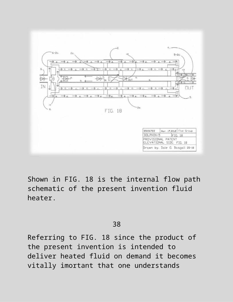
Shown in FIG. 18 is the internal flow path schematic of the present invention fluid heater.
26
Referring to FIG. 18 since the product of the present invention is intended to deliver heated fluid on demand it becomes vitally imortant that one understands completely the flow paths of the fluid and in specific how the multiple gradients of fluid temperature at the outlet for the end user is accomplished. In detail FIG. 18 shows a flow path of fluid in the start up position but it is anticipated by the inventor that this one FIG. 18 is sufficient for a current grasp on the dynamics of the present invention since the only apparent moving item is the fluid within the system port passages.
While the water within this container is pressurized it exerts a force at the inlet of 3. and fills passages a to the blocked outlet side of 2. which in turn backpressures the port inlet system and forces first into porting band c, and then porting band e and continues it’s flow path to the blocked valving at 4. No water flows at this point however as the heaters exchange their thermal heat into the heat exchanger metal block 2. the heat translates into band c first which occupies the smallest volume internally so in effect that coolant heats up quickly as compared to the e, band on the outer circumference farther out from the heat source. At that point the beverage water is super heated and can be used before the (a) coolant passage temperature sensitive flow restrictor valve r2 opens in the inner coolant passage a, at the outlet of heat exchanger 2.
27

Furthermore as the r2 valve heats and opens further, the inner cooling passage between the outlet of 2. inner cooling passage is allowed to flow into the r3 temperature sensitive restrictor valve which is also closed until a specific pre set temperature is reached and then that valve opens as it heats to a higher temperature from the heated fluid. The manually operated regulating valve is closed at the outlet bell 4. no fluid flows and heat is generated within the confined body of fluid as the heaters are energized by electricity. Taken now from the startup position whereas the water or fluid being at ambient temperature assumes the fluid cool and that upon the opening of r2 and r3 gives the end user the hottest possible water first through cooling band c. As the manual valve at the outlet bell of 4. is opened a pressure drop is felt across opening r1 allowing the cooler water to be backpressured into porting band e thus supplying cooler drinking water from that band outlet at 5. All cooling bands are referenced by the face ends of 2.
Now referencing elemental porting a in FIG. 18 the inner cooling passage which has the highest flow volume for showering and a lower temperature warm water outlet at 5a. All three cooling bands a, c, and e can be manually opened or closed and specifically after 4. outlet, to blend together for the perfect temperature desired by the end user of the product Dolphin 5 of the present invention fluid heater.
28

The regulated valving within the inner coolant porting passages is critical to the correct operation of the present invention fluid heater as well as the inside diameters of the outward cooling porting bands. These are critical to the correct operation of the fluid heater of the present invention Dolphin 5 as anticipated by the inventor.
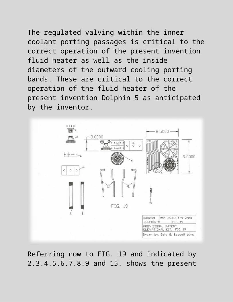
Referring now to FIG. 19 and indicated by 2.3.4.5.6.7.8.9 and 15. shows the present invention is assembleable and portable by indicating each element of the present invention fluid heater in it’s scaled form within a shipping box.
29

To assemble the present invention fluid heater product of this provisional patent draft an individual wanting to learn entry level skills is a prime candidate for assembly whereas the heat exchanger block 2. is the primary part of this invention as perceived by the inventor and by screwing one threaded end of the elongated hollow tube of 8. into the inlet side of the heat exchanger block 2. that matches the diameter of the inlet inner cooling tube end, tube 9. can then be rotated into the out face end of 2. at the inner cooling passage a. outlet. Then the inlet distribution manifold 6. is hand tightened to it’s open outlet end by rotating it onto the inlet inner cooling pipe open threaded end. The outlet distribution manifold 5. is then rotated onto the open end of the inner cooling tube outlet open end of 9. and also hand tightened. The inlet bell 3. is then rotated into the open end of the inlet distribution manifold center inner cooling port and hand tightened. The assemblies are then snugged together by rotating the inlet and outlet bells simutaneously in a clockwise direction until the inlet and outlet distribution manifolds porting is aligned at 22.5 degrees in relation to outer flats to heat exchanger 2. flat positions. This aligns all ports and allows for the outer cooling tube arrays to be installed. The product fluid heater is complete however when a container is used such as element 1. in FIG. 8 there are other steps to take for the completion of the final product as exampled in FIG. 2 and more specifically element 1. however it is simply chosing your container, or open system and so on. There are many variations of containment for the product fluid heater of the present invention.
30
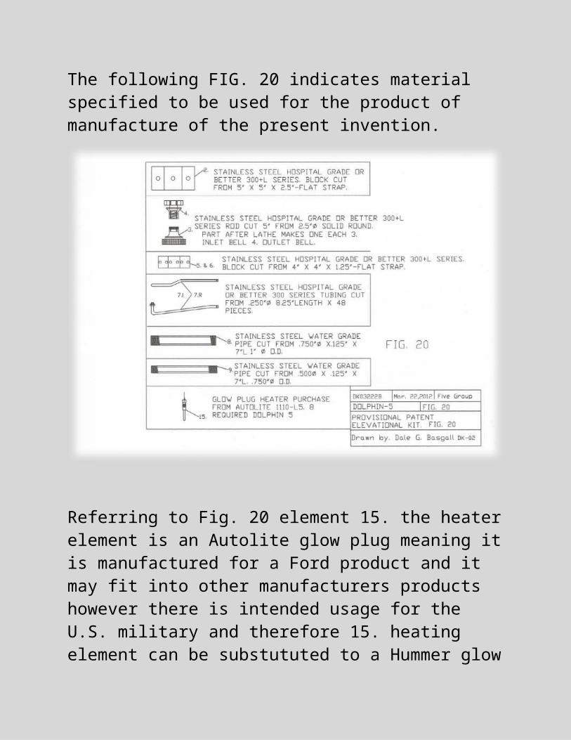
The following FIG. 20 indicates material specified to be used for the product of manufacture of the present invention.
Referring to Fig. 20 element 15. the heater element is an Autolite glow plug meaning it is manufactured for a Ford product and it may fit into other manufacturers products however there is intended usage for the U.S. military and therefore 15. heating element can be substututed to a Hummer glow plug which is readily available and retails for around 10 to 15 U.S. dollars making it easy to replace 15. whenever the need arises.
31
The 15. glow plug that fits a Hummer engine is a Bosh brand #80034 and the Dodge #CH-48 Champion brand, and the GMC #AC61G an AC Delco brand. These heating elements are sold in the millions which makes them very easy to purchase. This is very important in an emergency situation where scavenging parts may be the only replacement source.
It is thought that the fluid heater and method of the present invention and many of its attendant advantages will be understood from the foregoing description and it will be apparent that various changes may be made in the form, construction and arrangement of the parts thereof without departing from the spirit and scope of the invention or sacrificing all of its material advantages, the form herein described being merely a preferred or exemplary embodiment thereof.
32

FIG(s) THAT DID NOT MAKE THE PREFERRED LIST
33

34

35

36

37
38
39
40
41
42
CLAIM(S)I claim:
1. An article of manufacture for producing hot fluid quickly, comprising:
(a) means for cooling a heated metal block;
(b) means of dispencing said cooling means.
2. Fluid heater as recited in claim 1, wherein said means for cooling a heated metal block includes:
a pressurized cooling fluid;
an inlet bell having a hole;
an inlet manifold having a plurality of holes;
a heated metal block having a plurality of holes;
3. Fluid heater as recited in claim 1, wherein said means for dispencing said cooling means includes:
an outlet manifold having a plurality of holes; and
an outlet bell having a hole.
43

4. Fluid heater as recited in claim 2, wherein said means for cooling a heated metal block includes a pressurized cooling fluid including:
a container sealed airtight; and
the cooling fluid chosen by the end user.
5. Fluid heater as recited in claim 2, wherein said means for cooling a heated metal block includes an inlet bell having a hole includes:
a means for attaching the said inlet manifold onto the heated metal block and having a hole centrally bored through the said inlet bell.
6. Fluid heater as recited in claim 2, wherein said means for cooling a metal block includes an inlet manifold having a plurality of holes which includes;
a polar array of 8 holes positioned within a defined circular path and bored partially through the thickness and the circular path is defined and positioned centrally with a specific radius in the inner end face of the said manifold;
a central bore of a specific diameter through and positioned within the center of the said manifold as to allow coolant fluid to flow through; and
a circumferal array of 16 holes drilled inward as to adjoin porting for the distribution outward of cooling fluid through 24 cooling passages.
44
7. Fluid heater as recited in claim 2, wherein said means for cooling a heated metal block includes a heated metal block having a plurality of holes including:
a central bore of a specific diameter through and positioned within the center of the said heated metal block as to allow coolant fluid to flow through;
5 polar arrays of holes bored and centered outward from the center of the heated metal block end faces;
2 polar arrays of holes bored and centerd outward from the center of the heated metal block end faces are used for coolant fluid and there are 24 total; and
a circumferal array of 8 holes for the insertion of the heating elements.
8. Fluid heater as recited in claim 3, wherein said means for dispencing said coolant means includes an outlet manifold having a plurality of holes includes:
a central bore of a specific diameter through and positioned within the center of the said outlet manifold as to allow heated fluid to flow out;
3 polar arrays of holes bored and centered outward from the center of the outlet manifold end faces and are used for distributing fluid with multiple temperature gradients and there are 24 total used for heated coolant; and
45
an outward circumferal array of 16 holes as to allow the flow of heated coolant outward and is separate from the other polar array of heated coolant passages whereas an array of 40 heated coolant passage holes and is divided in two bands and including the center coolant passage the outlet is seperated 3 ways in circular band centerlines allowing final mixing of fluid temperature gradients to achieve the perfect temperature of the outlet fluid.
9. Fluid heater as recited in claim 3, wherein said means for dispencing said cooling means includes an outlet bell having a hole including:
a means for attaching the said outlet manifold onto the heated metal block and having a hole centrally bored through the said outlet bell; and
a means to dispence the heated fluid outward while keeping the fluids from the three heated coolant tubes seperated and released by choice individually.
46
ABSTRACT OF THE DISCLOSURE

A Fluid Heater that; is mobile and lightweight for people living in geographically isolated areas is comprised of electrically conducting elements that translate DCelectrical current flow into heat, directly through conduction. The thermal heat is translated into a metal block housing, and further into an outer polar array of fluid passages, and a singular center cooling passage. Water or other fluid types are forced to enter into a restricted inlet manifold and flow into the inlet end of a heated block. The fluid flow is blocked at the outlet of the heated block center cooling tube passage, and as a result the fluid back pressures within the center outlet port of the inlet distribution manifold. This in turn distributes back-pressured fluid into the outer cooling tube arrays of the inlet manifold and into the outer cooling tube bores in the heat exchanger block. The fluid continues through the external array of tubing thru the outer heat exchanger cooling ports and into the outer heated ports of the outlet distribution manifold and separate from the internal cooling tube conduit cavity centrally located within all three metal blocks. This fluid flow separation allows asimultaneous differential in water outlet temperatures, providing hot water for a beverage, or lower temperature water for showering and for the cleaning of a human body or animal, and also serves to achieve a specific temperature desired in the outlet flow of heated fluid.
47
FROM THE INVENTOR
TO
JOHN R. FLANAGAN
It was your hard work and inspiration to me by giving the notebook and the paperback of your book entitled HOW TO PREPARE PATENT APPLICATIONS that got me this far in writing. I appreciate your work and thank you for the opportunity for your assistance in filing the Provisional Draft. Should you need any more information for the Provisional Draft please let me know.
I would like to add though that I am not to good at writing the claims and I know they are not necessary for the provisional draft however I needed to declare them now and bottom line is that this fluid heater Dolphin 5 as described in the draft would not be the efficient product it is to be if the hole patterns are changed. Anyway there are other underlying reasons why this design came up and it is important that I declare them.
We the 5 group signed a working agreement and after discussions the reason we formed the 5 group was to research what the science community is terming LENR an acronym from the phrase Low Energy Nuclear Reaction.
48
No one has a working model, there has been no usefullness declared, it is still unstable and inconsistent and not proven

however there are several known facts that are claimed and the simple work is building a reactor. You can’t patent something that is not usefull yet.
The team goal is to develop a kit to allow others to Learn and expand the knowledge of this newly claimed energy using nickel and hydrogen and a few other things. This water heater was the basic foundation for a kit of some type that could be usefull right now in every day life and if LENR is ever developed there is a hole pattern I remained silent on in the provisional text and it is an array of cavities with the ability to hold a solid fuel such as the type that reacts with ocean water and produces thermal heat as a by product to warm ice divers.
Also the sealed container is not mentioned and if you view FIG. 17 you will view “the reactor” as a 5” x 5” cube and it is designed to fit inside a steel tube and I project in the future when and if this LENR is an everyday fact this particular reactor will be the more advanced and efficient model due to the symmetry of the geometry used to fomulate that small of package. I simply wanted to declare this now up front to Mr. Flanagan and the other team members.
49
