· web viewthat side of the coil must therefore always be connected to the negative terminal of...
TRANSCRIPT

Lesmahagow High School
Higher PhysicsWaves and Radiation
Summary Notes
Often to help us grasp a sense of scale newspapers compare things to everyday objects heights are measured in double-decker buses areas in football pitches etc However we do not experience the extremes of scale in everyday life so we use scientific notation to describe these Powers of 10 are referred to as orders of magnitude ie something a thousand times larger is three orders of magnitude bigger It would be useful to get an idea of scale to better understand how sub-nuclear and astronomical dimensions compare with those in our everyday life You can see how we fit into the grand scheme of things by carrying out the following activity
When we get into the world of the very small or very large it is difficult to get a picture of scale in our minds Below is a table giving some examples of scale in our world
Introduction
Orders of Magnitude
Today we know that atoms do not represent the smallest unit of matter In first year we learned that atoms are made up of a positively charged nucleus containing protons and neutrons with negatively charged electrons orbiting it The standard model attempts to explain everything in the universe in terms of fundamental particles A fundamental particle is one which cannot be broken down into anything else These fundamental particles are the building blocks of matter and the things which hold matter together
Thinking in terms of the smaller end of the scaleIf a proton is measured as having a radius of distance roughly 10-15m how many of these protons would fit on the point of a pencil Assuming the pencil point was 1mm across there would be 1 000 000 000 000 (1012) protons
In terms of the larger end of the scale we have space and quasars
The distance to a quasar is 1026 m
This would take light travelling at 3 x 10⁸ms 10 000 000 000 (109) years to get from Earth to the quasar
In the following table the numbers or words represented by the letters A B C D E F and G are missing Match each letter with the correct words from the list try and finish this table
Diameter of nucleusDiameter of proton
Diameter of SunDistance to nearest galaxy
Height of Ben NevisSize of a dust particle
Your height
The Standard Model
Historical Background
What is the World Made Of
The ancient Greeks believed the world was made of 4 elements (fire air earth and water) Democritus used the term lsquoatomrsquo which means ldquoindivisiblerdquo (cannot be divided) to describe the basic building blocks of life Other cultures including the Chinese and the Indians had similar concepts
Elements The Simplest Chemicals In 1789 the French chemist Lavoisier discovered through very precise measurement that the total mass in a chemical reaction stays the same He defined an element as a material that could not be broken down further by chemical means and classified many new elements and compounds
The Periodic Table ndash Order Out of Chaos
In 1803 Dalton measured very precisely the proportion of elements in various materials and reactions He discovered that they always occurred in small integer multiples This is considered the start of modern atomic theory In 1869 Mendeleev noticed that certain properties of chemical elements repeat themselves periodically and he organised them into the first periodic table
The Discovery of the Electron
In 1897 JJ Thomson discovered the electron and the concept of the atom as a single unit ended This marked the birth of particle physics Although we cannot see atoms using light which has too large a wavelength we can by using an electron microscope This fires a beam of electrons at the target and measures how they interact By measuring the reflections and shadows an image of individual atoms can be formed We cannot actually see an atom using light but we can create an image of one
The structure of atoms
At the start of modern physics at the beginning of the 20th century atoms were treated as semi-solid spheres with charge spread throughout them This was called the Thomson model after the physicist who discovered the electron This model fitted in well with experiments that had been done by then but a new experiment by Ernest Rutherford in 1909 would soon change this This was the first scattering experiment ndash an experiment to probe the structure of objects smaller than we can actually see by firing something at them and seeing how they deflect or reflect
The Rutherford alpha scattering experiment
Rutherford directed his students Hans Geiger and Ernest Marsden to fire alpha particles at a thin gold foil This is done in a vacuum to avoid the alpha particles being absorbed by the air
The main results of this experiment were
Most of the alpha particles passed straight through the foil with little or no deflection being detected between positions A and B
A few particles were deflected through large angles eg to position C and a very small number were even deflected backwards eg to position D
Rutherford interpreted his results as follows
The fact that most of the particles passed straight through the foil which was at least 100 atoms thick suggested that the atom must be mostly empty space
In order to produce the large deflections at C and D the positively charged alpha particles must be encountering something of very large mass and a positive charge
The discovery of the neutronPhysicists realised that there must be another particle in the nucleus to stop the positive protons exploding apart This is the neutron which was discovered by Chadwick in 1932 This explained isotopes ndash elements with the same number of protons but different numbers of neutrons
Science now had an elegant theory which explained the numerous elements using only three particles the proton neutron and electron However this simplicity did not last long
Matter and antimatterIn 1928 Paul Dirac found two solutions to the equations he was developing to describe electron interactions The second solution was identical in every way apart from its charge which was positive rather than negative This was named the positron and experimental proof of its existence came just four years later in 1932
(The positron is the only antiparticle with a special name ndash it means lsquopositive electronrsquo)
Almost everything we see in the universe appears to be made up of just ordinary protons neutrons and electrons However high-energy collisions revealed the existence of antimatter Antimatter consists of particles that are identical to their counterparts in every way apart from charge eg an antiproton has the same mass as a proton but a negative charge It is believed that every particle of matter has a corresponding antiparticle
AnnihilationWhen a matter particle meets an anti-matter particle they annihilate giving off energy Often a pair of high energy photons (gamma rays) are produced but other particles can be created from the conversion of energy into mass (using E = mc2) Anti-matter has featured in science fiction books and films such as Angels and Demons It is also the way in which hospital PET (Positron Emission Tomography) scanners work
The particle zooThe discovery of anti-matter was only the beginning From the 1930s onwards the technology of particle accelerators greatly improved and nearly 200 more particles have been discovered Colloquially this was known as the particle zoo with more and more new species being discovered each year A new theory was needed to explain and try to simplify what was going on This theory is called the Standard Model
The experimental proof for the positron came in the form of tracks left in a cloud chamber The rather faint photograph on the right shows the first positron ever identified The tracks of positrons were identical to those made by electrons but curved in the opposite direction
(You will learn more about cloud chambers and other particle detectors later in this unit)
The standard model was developed in the early 1970rsquos in an attempt to tidy up the number of particles being discovered and the phenomena that physicists were observing How do you examine a particle to see if it is actually made from more fundamental particles You smash it up
In a particle accelerator a very small particle eg an electron can be accelerated by electric and magnetic fields to a very high speed Being very small speeds near to the speed of light may be achieved When these particles collide with a stationary target or other fast-moving particles a substantial amount of energy is released in a small space Some of this energy may be converted into mass (E = mc2) producing showers of nuclear particles By passing these particles through a magnetic field and observing the deflection their mass and charge can be measured
For example an electron with low mass will be more easily deflected than its heavier cousin the Muon A positive particle will be deflected in the opposite direction to a negative particle Cosmic rays from outer space also contain particles which can be studied in a similar manner
Most matter particles such as protons electrons and neutrons have corresponding antiparticles These have the same rest mass as the particles but the opposite charge With the exception of the antiparticle of the electron (e-) which is the positron (e+) antiparticles are given the same symbol as the particle but with a bar over the top
When a particle and its antiparticle meet in most cases they will annihilate each other and their mass is converted into energy There are far more particles than antiparticles in the Universe so annihilation is extremely rare
At present physicists believe that there are 12 fundamental mass particles called Fermions which are split into two groups Leptons and QuarksThere are also 4 force mediating particles called Bosons The table below shows the fundamental particles [at the moment]
Motion Equations
Prefixes (National 5 only)
Quarks In 1964 Murray Gell-Mann proposed that protons and neutrons consisted of three smaller particles which he called lsquoquarksrsquo (pronounced kworks) There are two first generation quarks called up and down These make up neutrons and protons There are two 2nd generation quarks called charm and strange Finally there are two 3rd generation quarks called top and bottom Each quark has only a fraction (⅓ or ⅔) of the electron charge (16 times 10-19 C) These particles also have other properties such as spin colour quantum number and even something called strangeness which are not covered by this course
Quarks have been observed by carrying out deep-inelastic scattering experiments which use high energy electrons to probe deep into the nucleus However they have never been observed on their own only in twos or threes where they make up what are called hadrons
Hadrons
Baryons are made up of 3 quarks Examples include the proton and the neutron
The charge of the proton (and the neutral charge of the neutron) arise out of the fractional charges of their inner quarks This is worked out as follows
A proton consists of 2 up quarks and a down quark Total charge=+1 (23+ 2
3minus1
3 = 1)
A neutron is made up of 1 up quark and 2 down quarks No charge (23minus1
3minus1
3 = 0)
Mesons are made up of 2 quarks They always consist of a quark and an anti-quark pair
An example of a meson is a negative pion (Πndash = ū d) It is made up of an anti-up quark and a down
quark This gives it a charge of minus23minus1
3 = -1
Note A bar above a quark represents an antiquark eg ū is the anti-up quark (this is not the same as the down quark) The negative pion only has a lifetime of around 26 x 10 -8 s
Particles which are made up of quarks are called hadrons (the word hadron meant heavy particle) The Large Hadron Collider at CERN collides these particles There are two different types of hadron called baryons and mesons which depend on how many quarks make up the particle
1048576104857610485761048576104857610485761048576104857610485761048576104857610485761048576104857610485761048576104857610485761048576104857610485761048576104857610485761048576104857610485761048576104857610485761048576104857610485761048576104857610485761048576104857610485761048576104857610485761048576104857610485761048576104857610485761048576104857610485761048576104857610485761048576104857610485761048576104857610485761048576104857610485761048576104857610485761048576104857610485761048576104857610485761048576104857610485761048576104857610485761048576104857610485761048576104857610485761048576104857610485761048576104857610485761048576104857610485761048576104857610485761048576104857610485761048576104857610485761048576104857610485761048576104857610485761048576104857610485761048576104857610485761048576104857610485761048576104857610485761048576104857610485761048576104857610485761048576104857610485761048576104857610485761048576104857610485761048576104857610485761048576104857610485761048576104857610485761048576104857610485761048576104857610485761048576104857610485761048576104857610485761048576104857610485761048576104857610485761048576104857610485761048576104857610485761048576104857610485761048576104857610485761048576104857610485761048576104857610485761048576104857610485761048576104857610485761048576104857610485761048576104857610485761048576104857610485761048576
The Three Generations of leptons
Leptons are a different type of particle which include the familiar electron which is a first generation particle In addition there is a second (middle) generation electron called the muon and a third (heaviest) generation electron called the tau particle (The word lepton meant a light particle but the tau particle is actually heavier than the proton)
Neutrinos
All 3 leptons have a ldquoghostlyrdquo partner associated with it called the neutrino This has no charge (its name means little neutral one) There is an electron neutrino a muon neutrino and a tau neutrino Neutrinos were first discovered in radioactive beta decay experiments In beta decay a neutron in the atomic nucleus decays into a proton and an electron When physicists were investigating beta decay they came up with a possible problem the law of conservation of momentum appeared to be being violated
To solve this problem it was proposed that there must be another particle emitted in the decay which carried away with it the missing energy and momentum Since this had not been detected the experimenters concluded that it must be neutral and highly penetrating
This was the first evidence for the existence of the neutrino (In fact in beta-decay an anti-neutrino is emitted along with the electron as lepton number is conserved in particle reactions)
Interesting facts
More than 50 trillion (50x 1012) solar neutrinos pass through an average human body every second while having no measurable effect They interact so rarely with matter that massive tanks of water deep underground are required to detect them
Fundamental particles
The 6 quarks and 6 leptons are all believed to be fundamental particles That is physicists believe that they are not made out of even smaller particles It is possible that future experiments may prove this statement to be wrong (just as early 20th Century scientists thought that the proton was a fundamental particle)
1048576104857610485761048576104857610485761048576104857610485761048576104857610485761048576104857610485761048576104857610485761048576104857610485761048576104857610485761048576104857610485761048576104857610485761048576104857610485761048576104857610485761048576104857610485761048576104857610485761048576104857610485761048576104857610485761048576104857610485761048576104857610485761048576104857610485761048576104857610485761048576104857610485761048576104857610485761048576104857610485761048576104857610485761048576104857610485761048576104857610485761048576104857610485761048576104857610485761048576104857610485761048576104857610485761048576104857610485761048576104857610485761048576104857610485761048576104857610485761048576104857610485761048576104857610485761048576104857610485761048576104857610485761048576104857610485761048576104857610485761048576104857610485761048576104857610485761048576104857610485761048576104857610485761048576104857610485761048576104857610485761048576104857610485761048576104857610485761048576104857610485761048576104857610485761048576104857610485761048576104857610485761048576104857610485761048576104857610485761048576104857610485761048576104857610485761048576104857610485761048576104857610485761048576104857610485761048576104857610485761048576104857610485761048576104857610485761048576104857610485761048576104857610485761048576104857610485761048576
The Three Generations of leptons
Leptons are a different type of particle which include the familiar electron which is a first generation particle In addition there is a second (middle) generation electron called the muon and a third (heaviest) generation electron called the tau particle (The word lepton meant a light particle but the tau particle is actually heavier than the proton)
Neutrinos
All 3 leptons have a ldquoghostlyrdquo partner associated with it called the neutrino This has no charge (its name means little neutral one) There is an electron neutrino a muon neutrino and a tau neutrino Neutrinos were first discovered in radioactive beta decay experiments In beta decay a neutron in the atomic nucleus decays into a proton and an electron When physicists were investigating beta decay they came up with a possible problem the law of conservation of momentum appeared to be being violated
To solve this problem it was proposed that there must be another particle emitted in the decay which carried away with it the missing energy and momentum Since this had not been detected the experimenters concluded that it must be neutral and highly penetrating
This was the first evidence for the existence of the neutrino (In fact in beta-decay an anti-neutrino is emitted along with the electron as lepton number is conserved in particle reactions)
Interesting facts
More than 50 trillion (50x 1012) solar neutrinos pass through an average human body every second while having no measurable effect They interact so rarely with matter that massive tanks of water deep underground are required to detect them
Forces and Bosons
In the nucleus of every element other than hydrogen there is more than one proton The charge on each proton is positive so why donrsquot the protons fly apart breaking up the nucleus
1048576104857610485761048576104857610485761048576104857610485761048576104857610485761048576104857610485761048576104857610485761048576104857610485761048576104857610485761048576104857610485761048576 1048576104857610485761048576104857610485761048576104857610485761048576104857610485761048576104857610485761048576104857610485761048576104857610485761048576104857610485761048576104857610485761048576The particle responsible for carrying the strong force is called the gluon
The weak nuclear force is involved in radioactive beta decay It is called the weak nuclear force to distinguish it from the strong nuclear force but it is not actually the weakest of all the fundamental forces It is also an extremely short-range force
The electromagnetic force stops the electron from flying out of the atom The theory of the electromagnetic force and electromagnetic waves was created by the Scottish Physicist James Clerk Maxwell in the 19th Century
The final force is gravity Although it is one of the most familiar forces to us it is also one of the least understood
It may appear surprising that gravity is in fact the weakest of all the fundamental forces when we are so aware of its affect on us in everyday life However if the electromagnetic and strong nuclear forces were not so strong then all matter would easily be broken apart and our universe would not exist in the form it does today104857610485761048576104857610485761048576104857610485761048576104857610485761048576104857610485761048576104857610485761048576104857610485761048576104857610485761048576104857610485761048576104857610485761048576104857610485761048576104857610485761048576104857610485761048576104857610485761048576104857610485761048576104857610485761048576
104857610485761048576104857610485761048576104857610485761048576104857610485761048576104857610485761048576104857610485761048576104857610485761048576104857610485761048576
104857610485761048576104857610485761048576104857610485761048576104857610485761048576104857610485761048576104857610485761048576104857610485761048576104857610485761048576104857610485761048576104857610485761048576104857610485761048576104857610485761048576104857610485761048576104857610485761048576104857610485761048576104857610485761048576104857610485761048576104857610485761048576104857610485761048576
There is a short range force that exists that holds particles of the same charge together This force is stronger than the electrostatic repulsion that tries to force the particles apart We call it the strong force
This force acts over an extremely short range [approx 10-15 m] of the order of magnitude of a nucleus Outside of this range the strong force has no effect whatsoever If a proton was placed close to a nucleus it would be repelled and forced away
Force particles ndash The bosons
Each force has a particle associated with it which transmits the effects of that force The table below summarizes the current understanding of the fundamental forces
104857610485761048576
At an everyday level we are familiar with contact forces when two objects are touching each other Later in this unit you will consider electric fields as a description of how forces act over a distance At a microscopic level we use a different mechanism to explain the action of forces this uses something called exchange particles Each force is mediated through an exchange particle or boson
Many theories postulate the existence of a further boson called the Higgs boson (sometimes referred to as the lsquoGod particlersquo) which isnrsquot involved in forces but is what gives particles mass Attempts to verify its existence experimentally using the Large Hadron Collider at CERN and the Tevatron at Fermilab were rewarded on the 4th July 2012 when the announcement was made that the Higgs boson had been discovered
The Higgs boson plays a unique role in the Standard Model by explaining why the other elementary particles except the photon and gluon are massive In particular the Higgs boson would explain why the photon has no mass while the W and Z bosons are very heavy The Higgs itself is incredibly massive with a mass equivalent to that of 133 protons (10-25 kg)
104857610485761048576104857610485761048576104857610485761048576104857610485761048576104857610485761048576104857610485761048576104857610485761048576104857610485761048576104857610485761048576104857610485761048576104857610485761048576104857610485761048576
1048576104857610485761048576104857610485761048576104857610485761048576104857610485761048576104857610485761048576104857610485761048576104857610485761048576104857610485761048576104857610485761048576
Practical Uses of Antimatter Positron Emission Tomography (PET) Scanning 1048576
Positron emission tomography (PET) scanners use antimatter annihilation to obtain detailed 3-D scans of body function Other imaging techniques called CT and MRI scans can give detailed pictures of the bone and tissue within the body but PET scans give a much clearer picture of how body processes are actually working
A β+ tracer with a short half-life is introduced into the body attached to compounds normally used by the body such as glucose water or oxygen When this tracer emits a positron it will annihilate nearly instantaneously with an electron This produces a pair of gamma-ray photons of specific frequency moving in approximately opposite directions to each other (The reason it is only an approximately opposite direction is that the positron and electron are moving before the annihilation event takes place)
The gamma rays are detected by a ring of scintillators each producing a burst of light that can be detected by photomultiplier tubes or photodiodes Complex computer analysis traces tens of thousands of possible events each second and the positions of the original emissions are calculated A 3-D image can then be constructed often along with a CT or MRI scan to obtain a more accurate picture of the anatomy alongside the body function being investigated 10485761048576
The detecting equipment in PET scanners has much in common with particle detectors and the latest developments in particle accelerators can be used to improve this field of medical physics
Tracing the use of glucose in the body can be used in oncology (the treatment of cancer) since cancer cells take up more glucose than healthy ones This means that tumours appear bright on the PET image Glucose is also extremely important in brain cells which makes PET scans very useful for investigation into Alzheimerrsquos and other neurological disorders If oxygen is used as the tracking molecule PET scans can be used to look at blood flow in the heart to detect coronary heart disease and other heart problems
Forces on Charged Particles
Forces on Charged ParticlesIntroduction
You may wonder why it is important to study charged particles What use are they to us in everyday life Well without charged particles we wouldnrsquot have an electric current ndash unthinkable in our technological age But there are more applications you may not have thought of Laser printers and photocopiers use charged particles to get the toner to stick to the paper and car companies use charged particles to ensure that spray guns paint cars evenly The Large Hadron Collider accelerates positively charged protons to 99 the speed of light then collides them head on to try and recreate the conditions that existed when the Universe was 1100th of a billionth of a second old Scientists then study these collisions to try and explain what mass is and what 96 of the universe is made of In this section we will study how charged particles move in electric and magnetic fields We will then study the different types of particle accelerator and their applications
Force Fields
The idea of a field should be familiar to you In Physics a field means a region where an object experiences a force without being touched For example there is a gravitational field around the Earth This attracts masses towards the Earthrsquos centre Magnets cause magnetic fields and electric charges have electric fields around them
Electric FieldsIn an electric field a charged particle will experience a force We use lines of force to show the strength and direction of the force The closer the field lines the stronger the force Field lines are continuous they start on positive charge and finish on negative charge The direction is taken as the same as the force on a positive ldquotestrdquo charge placed in the field
Electric fields have a number of applications and play an important role in everyday life For example bull the cathode ray tube (the basis for traditional television and monitor systems)
bull paint spraying eg for cars bull photocopying and laser printing
bull pollution control
Stray electric fields can also cause problems for example during lightning storms there is a risk of damage to microchips within electronic devices caused by static electricity
If an electric field is applied to a conductor it will cause the free electrons in the conductor to move
Electric Field Patterns
These are called radial fields The lines are like the radii of a circle The strength of the field decreases as we move away from the charge 104857610485761048576
1048576104857610485761048576104857610485761048576104857610485761048576104857610485761048576104857610485761048576104857610485761048576
+ minus + +
The field lines are equally spaced between the parallel plates This means the field strength is constant This is called a uniform field 1048576104857610485761048576104857610485761048576104857610485761048576104857610485761048576104857610485761048576104857610485761048576104857610485761048576104857610485761048576104857610485761048576104857610485761048576104857610485761048576104857610485761048576104857610485761048576104857610485761048576104857610485761048576104857610485761048576104857610485761048576
Work Done10485761048576We have seen already that electric fields are similar to gravitational fields Consider the following
If a mass is lifted or dropped through a height then work is done ie energy is changed 1048576
104857610485761048576104857610485761048576If the mass is dropped then the energy will change to kinetic energy If the mass is lifted again then the energy will change to gravitational potential energy
Change in gravitational potential energy = work done
Now consider a negative charge moved through a distance in an electric field
If the charge moves in the direction of the electric force the energy will appear as kinetic energy If a positive charge is moved against the direction of the force as shown in the diagram the energy will be stored as electric potential energy 1048576
Definition of potential difference and the volt
Potential difference (pd) is defined to be a measure of the work done in moving one coulomb of charge between two points in an electric field Potential difference (pd) is often called voltage This gives the definition of the volt
There is a potential difference of 1 volt between two points if 1 joule of energy is required to move 1 coulomb of charge between the two points 1 V = 1 J Cminus1
This relationship can be written mathematically Ew = QV
Where Ew is energy (work done) in joules (J) Q is the charge in coulombs (C) and V is the potential difference (pd) in volts (V)
If the small positive charge above is released there is a transfer of energy to kinetic energy ie the charge moves Again using the conservation of energy means that
Ew = EK
QV = frac12mv2
Ew = QV
Ew = 30 times 10minus6 times 20 times 103
Ew = 60 times 10minus3 J
Example A positive charge of 30 microC is moved from A to B The potential difference between A and B is 20 kV
A B
minus +
minus
minus
+
+
+
(a) Calculate the electric potential energy gained by the chargendashfield system
(b) The charge is released Describe the motion of the charge
(c) Determine the kinetic energy when the charge is at point A
(d) The mass of the charge is 50 mg Calculate the speed of the charge
(a) Q = 30 C = 30 times 10minus6 C
V = 20 kV = 20 times 103 V
Ew =
(b) The electric field is uniform so the charge experiences a constant unbalanced force The charge accelerates uniformly towards the negative plate A
(c) By conservation of energy
EK = Ew = 60 times 10minus3 J
(d) m = 50 mg = 50 times 10minus6 kg
EK = 60 times 10minus3 J
v =
Ew = QV
Ew = 30 times 10minus6 times 20 times 103
Ew = 60 times 10minus3 J
EK = frac12mv2
60 times 10minus3 = 05 times 50 times 10minus6 times v2
v2 = 24 times 10minus3
v = 49 m sminus1
Charged Particles in Magnetic Fields
The discovery of the interaction between electricity and magnetism and the resultant ability to produce movement must rank as one of the most significant developments in physics in terms of the impact on everyday life
This work was first carried out by Michael Faraday whose work on electromagnetic rotation in 1821 gave us the electric motor He was also involved in the work which brought electricity into everyday life with the discovery of the principle of the transformer and generator in 1831 Not everyone could see its potential William Gladstone (1809ndash1898) the then Chancellor of the Exchequer and subsequently four-time Prime Minister of Great Britain challenged Faraday on the practical worth of this new discovery ndash electricity Faradayrsquos response was lsquoWhy sir there is every probability that you will soon be able to tax itrsquo The Scottish physicist James Clark Maxwell (1831ndash1879) built upon the work of Faraday and wrote down mathematical equations describing the interaction between electric and magnetic fields The computing revolution of the 20th century could not have happened without an understanding of electromagnetism
Magnetic Field Around A Current Carrying WireIn 1820 the Danish physicist Oersted discovered that a magnetic compass was deflected when an electrical current flowed through a nearby wire This was explained by saying that when a charged particle moves a magnetic field is generated In other words a wire with a current flowing through it (a current-carrying wire) creates a magnetic field
The magnetic field around a current-carrying wire is circular For electron flow the direction of the field can be found by using the left-hand grip rule
Summary
A stationary charge creates an electric field
A moving charge also creates a magnetic field
direction of electron flow
Moving charges experience a force in a magnetic fieldA magnetic field surrounds a magnet When two magnets interact they attract or repel each other due to the interaction between the magnetic fields surrounding each magnet
A moving electric charge behaves like a mini-magnet as it creates its own magnetic field This means it experiences a force if it moves through an external magnetic field (in the same way that a mass experiences a force in a gravitational field or a charge experiences a force in an electric field)
Simple rules can be used to determine the direction of force on a charged particle in a magnetic field
Movement of a negative charge in a magnetic field
Movement of a positive charge in a magnetic field
For a positive charge the direction of movement is opposite to the direction worked out above It is easiest to work out which way a negative charge would move using the right hand rule and then simply reverse this
If a charge travels parallel to the magnetic field it will not experience an additional force The direction of the force is determined using the same right hand rule The speed of the charge will not change only the direction of motion changes
One common method is known as the right-hand motor rule This is shown in the figure on the right The thumb gives the motion (M) the first finger gives the field (F) and the second finger is the direction of electron current (I)
Electron curves out of page Electron curves to the right No change in direction
The Electric MotorWhen a current-carrying wire is placed between the poles of a permanent magnet it experiences a force The direction of the force is at right-angles to
the direction of the current in the wire
the direction of the magnetic field of the permanent magnet
We can utilize this principle in the electric motor
field magnet
coil of wire brush
split ring commutator
N
direction of rotation
S
field magnet
An electric motor must spin continuously in the same direction Whichever side of the coil is nearest the north pole of the field magnets above must always experience an upwards force if the coil is to turn clockwise
That side of the coil must therefore always be connected to the negative terminal of the power supply Once the coil reaches the vertical position the ends of the coil must be connected to the opposite terminals of the power supply to keep the coil turning This is done by split ring commutator
In order for the coil to spin freely there cannot be permanent fixed connections between the supply and the split ring commutator Brushes rub against the split ring commutator ensuring that a good conducting path exists between the power supply and the coil regardless of the position of the coil
Particle Accelerators
Particle accelerators are used to probe matter They have been used to determine the structure of matter and investigate the conditions soon after the Big Bang Particle accelerators are also used produce a range of electromagnetic radiations which can be used in many other experiments
There are three main types of particle accelerators
linear accelerators cyclotrons synchrotrons
Regardless of whether the particle accelerator is linear or circular the basic parts are the same
a source of particles (these may come from another accelerator)Accelerators using electrons use thermionic emission in the same way as a cathode ray tube At the Large Hadron Collider (LHC) at CERN the source of particles is simply a bottle of hydrogen gas Electrons are stripped from the hydrogen atoms leaving positively charged protons These are then passed through several smaller accelerator rings before they reach the main beam pipe of the LHC
beam pipes (also called the vacuum chamber) Beam pipes are special pipes which the particles travel through while being accelerated There is a vacuum inside the pipes which ensures that the beam particles do not collide with other atoms such as air molecules
accelerating structures (a method of accelerating the particles)As the particles speed around the beam pipes they enter special accelerating regions where there is a rapidly changing electric field At the LHC as the protons approach the accelerating region the electric field is negative and the protons accelerate towards it As they move through the accelerator the electric field becomes positive and the protons are repelled away from it In this way the protons increase their kinetic energy and they are accelerated to almost the speed of light
a system of magnets (electromagnets or superconducting magnets as in the LHC)Newtonrsquos first law states that an object travels with a constant velocity (both speed and direction) unless acted on by an external force The particles in the beam pipes would go in a straight line if they were not constantly going past powerful fixed magnets which cause them to travel in a circle There are over 9000 superconducting magnets at the LHC in CERN These operate best at temperatures very close to the absolute 0K and this is why the whole machine needs to be cooled down If superconducting magnets were not used they would not be able to steer and focus the beam within such a tight circle and so the energies of the protons which are collided would be much lower
a target In some accelerators the beam collides directly with a stationary target such as a metal block In this method much of the beam energy is simply transferred to the block instead of creating new particles In the LHC the target is an identical bunch of particles travelling in the opposite direction The two beams are brought together at four special points on the ring where massive detectors are used to analyse the collisions
Nuclear ReactionsTo examine nuclear reactions it is necessary to define a number of terms used to describe a nucleus
Nucleon
A nucleon is a particle in a nucleus ie either a proton or a neutron
Atomic Number
The atomic number Z equals the number of protons in the nucleus In a chemical symbol for an element it is written as a subscript before the element symbol
Example There are 92 protons in the nucleus of a uranium atom so we write 92U
Mass Number
The mass number A is the number of nucleons in a nucleus In a chemical symbol for an element it is written as a superscript before the element symbol
Example One type of atom of uranium has 235 nucleons so we write 235U
Each element in the periodic table has a different atomic number and is identified by that number It is possible to have different versions of the same element called isotopes An isotope of a atom has the same number of protons but a different number of neutrons ie the same atomic number but a different mass number An isotope is identified by specifying its chemical symbol along with its atomic and mass numbers For example
Radioactive DecayRadioactive decay is the breakdown of a nucleus to release energy and matter from the nucleus This is the basis of the word lsquonuclearrsquo The release of energy andor matter allows unstable nuclei to achieve stability Unstable nuclei are called radioisotopes or radionuclides
Representation of decay by symbols and equations In the following equations both mass number and atomic number are conserved ie the totals are the same before and after the decay The original radionuclide is called the parent and the new radionuclide produced after decay is called the daughter product
Alpha decay Uranium 238 decays by alpha emission to give Thorium 234
Mass number decreases by 4 atomic number decreases by 2 (due to loss of 2 protons and 2 neutrons)
Alpha decay usually occurs in heavy nuclei such as uranium or plutonium and therefore is a major part of the radioactive fallout from a nuclear explosion Since an alpha particle is relatively more massive than other forms of radioactive decay it can be stopped by a sheet of paper and cannot penetrate human skin A 4 MeV alpha particle can only travel a few centimetres through the air Although the range of an alpha particle is short if an alpha decaying element is ingested the alpha particle can do considerable damage to the surrounding tissue This is why plutonium with a long half-life is extremely hazardous if ingested
Beta decay Atoms emit beta particles through a process known as beta decay Beta decay occurs when an atom has either too many protons or too many neutrons in its nucleus Two types of beta decay can occur One type (positive beta decay) releases a positively charged beta particle called a positron and a neutrino the other type (negative beta decay) releases a negatively charged beta particle called an electron and an antineutrino The neutrino and the antineutrino are high-energy elementary particles with little or no mass and are released in order to conserve energy during the decay process Negative beta decay is far more common than positive beta decay Lead 210 decays by beta emission to give Bismuth 210
Mass number is unchanged atomic number increases by 1
Gamma decay Gamma rays are a type of electromagnetic radiation that results from a redistribution of electric charge within a nucleus Gamma rays are essentially very energetic X - rays the distinction between the two is not based on their intrinsic nature but rather on their origins X rays are emitted during atomic processes involving energetic electrons Gamma radiation is emitted by excited nuclei or other processes involving subatomic particles it often accompanies alpha or beta radiation as a nucleus emitting those particles may be left in an excited (higher-energy) state 6
7 Gamma rays are more penetrating than either alpha or beta radiation but less ionising Gamma rays from nuclear fallout would probably cause the largest number of casualties in the event of the use of nuclear weapons in a nuclear war They produce damage similar to that caused by X-rays such as burns cancer and genetic mutations
Example
Thorium 230 decays into Radon State the name of the particle emitted and give the equation for this decay (Atomic number of Thorium is 90 and that of Radon is 88)
Solution
Because the atomic number of Radon is less than Thorium an alpha particle must have been emitted
Nuclear Fission
Fission occurs when a heavy nucleus disintegrates forming two nuclei of smaller mass number This radioactive decay is spontaneous fission In this decay process the nucleus will split into two nearly equal fragments and several free neutrons A large amount of energy is also released Most elements do not decay in this manner unless their mass number is greater than 230
Fission can also be induced (persuaded to happen) by neutron bombardment
This is what happens in a nuclear reactor and is given by the equation
Mass number and atomic number are both conserved during this reaction Even though the mass number is conserved when the masses before and after the fission are compared accurately there is a mass difference The total mass before fission is greater than the total mass of the products
Einstein suggested that mass was a form of energy and that when there was a decrease in mass an equivalent amount of energy was produced
The stray neutrons released by a spontaneous fission can prematurely initiate a chain reaction This means that the assembly time to reach a critical mass has to be less than the rate of spontaneous fission Scientists have to consider the spontaneous fission rate of each material when designing nuclear weapons or for nuclear power For example the spontaneous fission rate of plutonium 239 is about 300 times larger than that of uranium 235
Energy In A Fission Reaction
Einsteinrsquos famous equation shows how mass and energy are related
In fission reactions the energy released is carried away as kinetic energy of the fission products Fission reactions take place in nuclear reactors The neutrons released are fast moving A moderator eg graphite is used to slow them down and increase the chance of further fissions occurring
A chain reaction refers to a process in which neutrons released in fission produce an additional fission in at least one further nucleus This nucleus in turn produces neutrons and the process repeats The process may be controlled (nuclear power) or uncontrolled (nuclear weapons)
These slow (thermal) neutrons cause a chain reaction so that more fissions occur Control rods eg boron absorb some of the slow neutrons and keep the chain reaction under control The kinetic energy of the fission products converts to heat in the reactor core
Example Calculate the energy released during this fission reaction
Nuclear fission in nuclear reactors
Controlled fission reactions take place in nuclear reactors The neutrons released are fast moving
A moderator eg graphite is used to slow them down and increase the chance of further fissions ccurring
These slow (thermal) neutrons cause a chain reaction so that more fissions occur
Control rods eg boron absorb some of the slow neutrons and keep the chain reaction under control
The energy of the moving fission products is transferred by heating in the reactor core
A coolant fluid (liquid or gas) is required to avoid the core overheating and in addition it can act as a moderator
The fluid turns into steam and this drives the turbines
Fission reactors require containment within reinforced concrete and lead-lined containers to reduce contamination
Nuclear Fusion
Nuclear energy can also be released by the fusion of two light elements (elements with low atomic numbers)
In a hydrogen bomb two isotopes of hydrogen deuterium and tritium are fused to form a nucleus of helium and a neutron
Unlike nuclear fission there is no limit on the amount of the fusion that can occur The immense energy produced by our Sun is as a result of nuclear fusion
Very high temperatures in the Sun (23 times 107 K according to NASA) supply sufficient energy for nuclei to overcome repulsive forces and fuse together When nuclei fuse the final mass is less than the initial mass ie there is a mass difference or mass defect The energy produced can be calculated using
Fusion Example
01n
24He
13H
12H
The nuclear reaction can be represented by
2
1 H
3
1 H
4
2 He
1
0 n + + + energy
deuterium + tritium -particle + neutron + energy
Once again it is found that the total mass after the reaction is less than the total mass before This reduction in mass appears as an increase in the kinetic energy of the particles
Mass before fusion (m1) deuterium 3middot345 times 10minus27 kgtritium 5middot008 times 10minus27 kg total 8middot353 times 10minus27 kg
Mass after fusion (m2) -particle 6middot647 times 10minus27 kgneutron 1middot675 times 10minus27 kgtotal 8middot322 times 10minus27 kg
Loss of mass (m1 - m2) m 0 middot031 times 10 minus27 kg
Energy released E = mc2
= 0middot031 times 10minus27 times (3middot0 times 108)2
= 2middot8 times 10minus12 J
A Fusion Reactor
To sustain fusion 3 conditions must be met at the same time
Extremely high plasma temperature (T) 100ndash200 million K
A stable reaction lasting at least 5 seconds This is called the energy confinement time (t)
A precise plasma density of around 1020 particlesm3
(This is one thousandth of a gramm3 = one millionth the density of air)
Fusion has been successfully achieved with the hydrogen bomb However this was an uncontrolled fusion reaction and the key to using fusion as an energy source is control
The Joint European Torus (JET) in Oxfordshire is Europersquos largest fusion device In this device deuteriumndashtritium fusion reactions occur at over 100 million kelvin Even higher temperatures are required for deuteriumndashdeuterium and deuteriumndashhelium 3 reactions
One type of fusion reactor is called a Tokomak In this design the plasma is heated in a torus or ldquodoughnut-shapedrdquo vessel
The hot plasma is kept away from the vessel walls by applied magnetic fields This is shown in the diagram on the right
One of the main requirements for fusion is to heat the plasma particles to very high temperatures or energies The methods on the following page are typically used to heat the plasma ndash all of them are employed on JET
Induced current The main plasma current is induced in the plasma by the action of a large transformer A changing current in the primary coil induces a powerful current (up to 5 million amperes on JET) in the plasma which acts as the transformer secondary circuit
Neutral beam heating Beams of high energy (neutral) deuterium or tritium atoms are injected into the plasma transferring their energy to the plasma via collisions with the ions
Radio-frequency heating Electromagnetic waves of a frequency matched to the ions or electrons are able to energise the plasma particles This is similar to the accelerating structures in a particle accelerator
Self-heating of plasma The helium ions (or so-called alpha-particles) produced when deuterium and tritium fuse remain within the plasmarsquos magnetic trap for a time before they are pumped away through the diverter The neutrons (being neutral) escape the magnetic field and their capture in a future fusion power plant will be the source of fusion power to produce electricity
Breakeven and Ignition When fusion power out just equals the power required to heat and sustain plasma then breakeven is achieved However only the fusion energy contained within the helium ions heats the deuterium and tritium fuel ions (by collisions) to keep the fusion reaction going When this self-heating mechanism is sufficient to maintain the plasma temperature required for fusion the reaction becomes self-sustaining (ie no external plasma heating is required) This condition is referred to as ignition In magnetic plasma confinement of the DndashT fusion reaction the condition for ignition is approximately six times more demanding (in confinement time or in plasma density) than the condition for breakeven
Wave-Particle DualityThe Photoelectric Effect
He observed that the sparks at the receiver were much bigger when light from the large transmitter sparks was allowed to fall on the receiving spheres Hertz did not follow this up but others did What Hertz had discovered was the photoelectric effect
In 1887 Heinrich Hertz was experimenting with radio waves
Under certain situations an electrically charged object can be made to discharge by shining electromagnetic radiation at it This can be best demonstrated by charging a device on which the charge stored can be measured either a digital coulombmeter or a gold leaf electroscope As charge is added to a gold leaf electroscope the thin piece of gold leaf rises up at an angle from the vertical rod to which it is attached
gold leaf
metal plate
digital coulombmeter gold leaf electroscope
It is found that the electroscope will only discharge if it is negatively charged and the incident light is of a sufficiently high frequency What does this mean How do we explain our results
Well the UV radiation is causing electrons to leave the metal making it discharge We call these electrons photoelectrons We know that all electromagnetic waves deliver energy so if they deliver enough energy to a particular electron surely that electron could use the energy to leave the metal surface
So why is that low frequency (long wavelength) radiation wont eject electrons but waves of higher frequency will Wave theory says that any wave will deliver energy so surely if you shine any radiation onto the metal for long enough eventually enough energy will be delivered to allow electrons to leave But this is not the case
The effect can only be explained if we consider that electromagnetic radiation does not always behave like a wave - a smooth continuous stream of energy being delivered to a point In this case you can only explain the effect if the radiation is behaving like packets of energy being delivered one by one We call these packets of energy quanta or photons
The idea that light could be delivered as packets of energy was initially put forward by Max Planck Albert Einstein applied this theory to the photoelectric effect It is for this work that he obtained the Nobel prize in 1921 Modern physics now takes the view that light can act both like a wave and like a particle without contradiction This is known as wave-particle duality
We can see that electrons are emitted if the following conditions are met
the radiation must have a high enough frequency (or short enough wavelength) the surface must be suitable ndash the energy in UV radiation will not eject electrons from iron
copper lead etc but will from sodium and potassium although these are a bit tricky to use
Each photon has a frequency and wavelength associated with it just as a wave in the wave theory had However each photon has a particular energy that depends on its frequency given by the equation below
Where E = energy of the photon (J) f = frequency of the photon (Hz) h = Planckrsquos constant = 663 times 10-34 J s
From this equation it can be seen that the energy of each photon is directly proportional to its frequency The higher the frequency the greater the energy
Different frequencies of electromagnetic radiation can be directed at different types of charged metals The metals can be charged either positively or negatively
In most circumstances nothing happens when the electromagnetic radiation strikes the charged metal for example the first two below However in a few cases such as the third a negatively charged metal can be made to discharge by certain high frequencies of electromagnetic radiation
We can explain this photoelectric effect in terms of electrons within the metal being given sufficient energy to come to the surface and be released from the surface of the metal The negative charge on the plate ensures that the electrons are then repelled away from the electroscope
This cannot be explained by thinking of the light as a continuous wave The light is behaving as if it were arriving in discrete packets of energy the value of which depends on the wavelength or frequency of the light Einstein called these packets of energy photons
The experimental evidence shows that photoelectrons are emitted from a metal surface when the metal surface is exposed to optical radiation of sufficient frequency In the third case any photoelectrons which are emitted from the metal surface are immediately attracted back to the metal because of the attracting positive charge on the electroscope The electroscope does not therefore discharge
It is important to realise that if the frequency of the incident radiation is not high enough then no matter how great the irradiance of the radiation no photoelectrons are emitted This critical or threshold frequency fo is different for each metal For copper the value of fo is even greater than that of the ultraviolet part of the spectrum as no photoelectrons are emitted for ultraviolet radiation Some metals such as selenium and cadmium exhibit the photoelectric effect in the visible light region of the spectrum
One reason why different metals have different values of fo is that energy is required to bring an electron to the metal surface and due to the different arrangements of atoms in different metals Some metals will hold on to their electrons a little stronger than others The name given to the small amount of energy required to bring an electron to the surface of a metal and free it from that metal is the work function
Threshold frequency and work function In general there is a minimum frequency of electromagnetic radiation required in order to eject electrons from a particular metal This is called the threshold frequency fo and is dependent on the surface being irradiated
Such an electron would escape but would have no kinetic energy If the energy of the incoming electron E = hf is greater than the work function then the extra energy will appear as kinetic energy of the electron
The minimum energy required to release an electron from a surface is called the work function Eo of the surface
N4 N5
If a photon of incident radiation carries more energy than the work function value then the electron not only is freed at the surface but has ldquosparerdquo kinetic energy and it can go places An experiment can be carried out to demonstrate and quantify the photoelectric effect
current
frequency 0 fo
current
irradiance 0
Notice that the supply is opposing the electron flow
Initially with the supply pd set at 0 V light of various wavelengths or frequencies is allowed to fall on the photocathode In each case a small current is observed on the microammeter The value of this current can be altered by altering the irradiance of the light as this will alter the number of photons falling on the cathode and thus the number of photoelectrons emitted from the cathode In fact the photocurrent is directly proportional to the irradiance of the incident light - evidence that irradiance is related to the number of photons arriving on the surface
If when red light only is used the pd of the supply is slowly turned up in such a direction to oppose the electron flow there comes a point when the pd is just sufficient to stop all the photoelectrons from reaching the anode This is called the stopping potential for red The photoelectrons are just not reaching the anode as they have not sufficient kinetic energy to cross the gap to the anode against the electric field In fact their kinetic energy has all been turned to potential energy and they have come to rest
If the red light is now replaced with violet light and no other alterations are made a current suddenly appears on the microammeter This means that some electrons are now managing to get across from the cathode to the anode Hence they must have started out their journey with more kinetic energy than those produced by red light This means that photons of violet light must be carrying more energy with them than the photons of red light No matter how strong the red light source is or how weak the violet light source the photons of violet light always ldquowinrdquo
If several experiments are done with photocells with different metal cathodes and in each case a range of different frequencies of light is used graphs of maximum energy of photoelectrons against frequency of light can be plotted as follows
All metals are found to give straight line graphs which do not pass through the origin However the gradient of each line is the same This gradient is Planckrsquos constant h
The value of Planckrsquos constant is 6middot63 times 10minus34 Js The work function of the metal is the intercept on the energy axis
From the straight line graph it can be seen that
y = mx + c
Ek = mf + c
Ek = hf ndash W
Hence
hf = W +Ek or hf = hfo +Ek
energy of absorbed photon = work function + kinetic energy of emitted electron
Irradiance of photons If N photons of frequency f are incident each second on each one square metre of a surface then the energy per second (power) absorbed by the surface is
The irradiance I at the surface is given by the power per square metre
Where I = irradiance in W mminus2
h = Planckrsquos constant in J s f = frequency in Hz N = no of photons
Note
The energy transferred to the electrons depends only on the frequency of the photons Higher irradiance radiation does not increase the velocity of the electrons it produces more electrons of the same velocity
ExampleA semiconductor chip is used to store information The information can only be erased by exposing the chip to UV radiation for a period of time The following data is provided Frequency of UV used = 90 x 1014 Hz Minimum irradiance of UV radiation required at the chip = 25 Wmminus2
Area of the chip exposed to radiation = 18 x 10minus9 m2
Energy of radiation needed to erase the information = 405 mJ
a) Calculate the energy of a photon of the UV radiation used b) Calculate the number of photons of the UV radiation required to erase the information
Solution
a)E = hf = 663 x 10minus34 x 90 x 1014 = 5967x10minus19J
b) Energy of radiation needed to erase the information Etotal = 405 mJ Etotal = N(hf) 405 x 10minus6 = N x 5967 x 10minus19
N = 405 x 10minus6 5967x10minus19
N = 679 x 1013
Waves RevisionArea to look overAmplitude wavelength crests and troughs Period of a wave Frequency Wave speed Reflection refraction and Diffraction
Phase and CoherencePhase
Two points on a wave that are vibrating in exactly the same way at the same time are said to be in phase eg two crests or two troughs
Two points that are vibrating in exactly the opposite way at the same time are said to be exactly out of phase or 180o out of phase eg a crest and a trough
v
A
B
C
D
E
F
G
H
Points _A_ amp _E_ or _B_ amp _H_ are in phase
Points _A_ amp _C_ or _C_ amp _E_ or _D_ amp _G_ are exactly out of phase
Points _C_ amp _D_ or _D_ amp _E_ or _E_ amp _G are 90deg out of phase
Points _D_ and G_ are at present stationary
Points _A_ _E_ and _F_ are at present rising
Points _B _C_ and _H_ are at present dropping
Coherent SourcesTwo sources that are oscillating with a constant phase relationship are said to be coherent This means the two sources also have the same frequency Interesting interference effects can be observed when waves with a similar amplitude and come from coherent sources meet
InterferenceWhen two or more waves meet superposition or adding of the waves occurs resulting in one waveform
Constructive Interference
When the two waves are in phase constructive interference occurs
Destructive Interference
When the two waves are exactly out of phase destructive interference occurs
Only waves show this property of interference Therefore interference is the test for a wave
+ =
+ =
Interference can be demonstrated by allowing waves from one source to diffract through two narrow slits in a barrier This can be done with water waves in a ripple tank microwaves and light
Laser
grating screen
microwave transmitter metal plates
microwave detector
Interference of water waves
If two point sources produce two sets of circular waves they will overlap and combine to produce an interference pattern The semicircular lines represent crests the troughs are between the crests
The points of constructive interference form waves with larger amplitude and the points of destructive interference produce calm water The positions of constructive interference and destructive interference form alternate lines which spread out from between the sources As you move across a line parallel to the sources you will therefore encounter alternate large waves and calm water
S1 and S2 are coherent point sources ie the waves are produced by the same vibrator
X = point of constructive interference
O = point of destructive interference
____ = line of constructive interference
- - - - = line of destructive interference
Interference of sound waves
If we set up the apparatus as shown and walk slowly across the lsquopatternrsquo as shown above We should be able to listen to the effect on the loudness of the sound heard The effect heard happens as there will be points where the sound is louder [constructive interference] and points where the sound is quieter [destructive interference] The waves that meet at your ear will have travelled different distances from each loudspeaker The difference in distance is known as the path difference
Interference of lightTwo sources of coherent light are needed to produce an interference pattern Two separate light sources such as lamps cannot be used to do this as there is no guarantee that they will be coherent (same phase difference) The two sources are created by producing two sets of waves from one monochromatic (single frequency) source A laser is a good source of this type of light
When we set up an experiment like the one shown we see an alternate series of light and dark lines
Where the light arrives in phase this is an area of constructive interference and a bright fringe is seen Where the light arrives out of phase this is an area of destructive interference and a dark fringe is seen
Interference can only be explained in terms of wave behaviour and as a result interference is taken as proof of wave motion
Interference Patterns
S1
S2
S1
S2
S1
S2
Sources S1 and S2 in phase and 5 cm apart wavelength 1 cm
Sources S1 and S2 in phase and 5 cm apart wavelength 2 cm
Sources S1 and S2 in phase and 3 cm apart wavelength 1 cm
Interference and Path DifferenceConstructive
Two sources S1 and S2 in phase and 3 cm apart wavelength 1 cm S1
S2
P0
P0 is a point on the centre line of the interference pattern P0 is the same distance from S1 as it is from S2 The path difference between S1P0 and S2P0 = 0 Waves arrive at P0 in phase and therefore constructive interference occurs
S1
S2
P0
P1
P1 is a point on the first line of constructive interference out from the centre line of the interference pattern
P1 is one wavelength further from S2 than it is from S1 The path difference between S1P1 and S2P1 = 1 times Waves arrive at P1 in phase and therefore constructive interference occurs
S1
S2
P0
P1
P2
P2 is a point on the second line of constructive interference out from the centre line of the interference pattern
P2 is one wavelength further from S2 than it is from S1 The path difference between S1P2 and S2P2 = 2 times Waves arrive at P2 in phase and therefore constructive interference occurs
Constructive interference occurs when
path difference = m where m is an integer
Destructive
P0
P1
P2
P05
P15
S1
S2
Destructive interference occurs whenpath difference = ( m + frac12 ) where m is an integer
Solutiona) The student hears a series of loud and quiet sounds due to interference of the two sets of sound
waves from the loudspeakers When the two waves are in phase there is constructive interference and when the two waves are exactly out of phase there is destructive interference
b) v = f340 = 500 times = 0middot68 m
c) Path difference = 5middot78 ndash 4middot76 = 1middot02 m Number of wavelengths = 1middot020middot68 = 1middot5 A path difference of 1middot5 means the waves are exactly out of phase The student hears a quiet
soundd) In a small room sound waves will reflect off the walls and therefore other sound waves will also
interfere with the waves coming directly from the loudspeakers
ExampleA student sets up two loudspeaker a distance of 1middot0 m apart in a large room The loudspeakers are connected in parallel to the same signal generator so that they vibrate at the same frequency and in phase
signal generator
B
A The student walks from A and B in front of the loudspeakers and hears a series of loud and quiet sounds
a) Explain why the student hears the series of loud and quiet soundsb) The signal generator is set at a frequency of 500 Hz The speed of sound in the room is 340 m sminus1
Calculate the wavelength of the sound waves from the loudspeakersc) The student stands at a point 4middot76 m from loudspeaker and 5middot78 m from the other loudspeaker State the
loudness of the sound heard by the student at that point Justify your answerd) Explain why it is better to conduct this experiment in a large room rather than a small room
Thomas Young
In 1801 Young devised and performed an experiment to measure the wavelength of light It was important that the two sources of light that form the pattern be coherent The difficulty confronting Young was that the usual light sources of the day (candles lanterns etc) could not serve as coherent light sources Youngs method involved using sunlight that entered the room through a pinhole in a window shutter A mirror was used to direct the pinhole beam horizontally across the room To obtain two sources of light Young used a small paper card to break the single pinhole beam into two beams with part of the beam passing by the left side of the card and part of the beam passing by the right side of the card Since these two beams emerged from the same source - the sun - they could be considered coming from two coherent sources Light waves from these two sources (the left side and the right side of the card) would interfere The interference pattern was then projected onto a screen where measurements could be made to determine the wavelength of light
Todays classroom version of the same experiment is typically performed using a laser beam as the source Rather than using a note card to split the single beam into two coherent beams a carbon-coated glass slide with two closely spaced etched slits is used The slide with its slits is most commonly purchased from a manufacturer who provides a measured value for the slit separation distance - the d value in Youngs equation Light from the laser beam diffracts through the slits and emerges as two separate coherent waves The interference pattern is then projected onto a screen where reliable measurements can be made for a given bright spot with order value m Knowing these values allows a student to determine the value of the wavelength of the original light source
Youngrsquos Double Slit ExperimentIn 1801 Thomas Young showed that an interference pattern could be produced using light At the time this settled the long running debate about the nature of light in favour of light being a wave
screen
double slit single slit
lamp
Passing light from the lamp through the single slit ensures the light passing through the double slit is coherent An interference pattern is observed on the screen
O central
(zero order)
maximum
P first
order
maximum x
D
S1
S2
d
The path difference between S1P and S2P is one wavelengthAs the wavelength of light is very small the slits separation d must be very small and much smaller than the slits to screen distance D Angle between the central axis and the direction to the first order maximum is therefore very small For small angles sin is approximately equal to tan and the angle itself if measured in radians
Hence from the two similar triangles
To produce a widely spaced fringe pattern
(a) Very closely separated slits should be used since x 1d
(b) A long wavelength light should be used ie red since x
(Wavelength of red light is approximately 7middot0 times 10 -7 m green light approximately 5middot5 times 10-7 m and blue light approximately 4middot5 x 10-7 m)
(c) A large slit to screen distance should be used since x D
1 2
Gratings
A double slit gives a very dim interference pattern since very little light can pass through the two narrow slits Using more slits allows more light through to produce brighter and sharper fringes
d
1
d
2
2
As in Youngrsquos Double Slit Experiment the first order bright fringe is obtained when the path difference between adjacent slits is one wavelength
Therefore
sin1 = λd and = d sin1
The second order bright fringe is obtained when the path difference between adjacent slits is two wavelengths 2
Therefore
sin2 = 2λd and 2 = d sin 2
The general formula for the m th order spectrum is m = d sin
The Grating
A grating consists of many equally spaced slits positioned extremely close together Light is diffracted through each slit and interference takes place in a similar fashion to the double slit we used when we investigated the interference of light The advantage of the grating is that it has many more slits (up to 7500 per mm in our school set) so much more light is transmitted through and a clearer interference pattern is seen
Where m = order of the maximum λ = wavelength of light d = separation of slits θ = angle from zero order to mth maximum
Gratings and White Light
It is possible to use a grating to observe the interference pattern obtained from a white light source Since white light consists of many different frequencies (wavelengths) the fringe pattern produced is not as simple as that obtained from monochromatic light
The central fringe is white because at that position the path difference for all wavelengths present is zero therefore all wavelengths will arrive in phase The central fringe is therefore the same colour as the source (in this case white)
The first maximum occurs when the path difference is 1 Since blue light has a shorter wavelength than red light the path difference will be smaller so the blue maximum will appear closer to the centre Each colour will produce a maximum in a slightly different position and so the colours spread out into a spectrum
These effects can also be explained using the formula m= dsinθ If d and m are fixed the angle θ depends on the wavelength So for any given fringe number the red light with a longer wavelength will be seen at a greater angle than the blue light The higher order spectra overlap
Comparing Spectra from Prisms and Gratings
Only one spectrum produced Red deviated least violet the most Bright images Usually less widely spaced (dispersed)
Many spectra produced symmetrical about the central maximum Red deviated most violet the least Less intense ndash energy divided between several spectra Usually more spread out Central image always the same colour as the source
Refraction
Have you ever wondered why a straight stick appears bent when partially immersed in water the sun appears oval rather than round when it is about to set or the pavement shimmers on a hot summers day Could you explain why diamonds sparkle or how a rainbow is formed These are some of the effects caused by the refraction of light as it passes at an angle from one medium to another In this section we will study refraction and its applications
RefractionRefraction is the property of light which occurs when it passes from one medium to another While in one medium the light travels in a straight line Light and other forms of electromagnetic radiation do not require a medium through which to travel
Light travels at its greatest speed in a vacuum Light also travels at almost this speed in gases such as air The speed of any electromagnetic radiation in space or a vacuum is 3middot00 times 108 m s-1
Whenever light passes from a vacuum to any other medium its speed decreases Unless the light is travelling perpendicular (900) to the boundary between the media this then results in a change in direction
It is the change in the speed of the light that causes refraction The greater the change in speed the greater the amount of refraction
Media such as glass perspex water and diamond are optically more dense than a vacuum Air is only marginally more dense than a vacuum when considering its optical properties
Refractive IndexIf we carry out the experiment below
We find that the graph gives a straight line This shows that sin θ1 sin θ2 = k
This constant is known as the refractive index and is given the symbol n
sin θ1 sin θ2 = n
The absolute refractive index of a material n is the refractive index of that material compared to the refractive index of a vacuum The absolute refractive index of a vacuum (and therefore also air) is 1middot0
Snellrsquos Law
n1 sin 1 = n2 sin 2
Where medium 1 is a vacuum or air and therefore n1 = 1middot0 this simplifies to
sin 1 = n2 sin 2 or n= Sinθ 1
Sinθ 2 (remember only when 1 is in air )If the refraction occurs between any 2 mediums though we can still use
n1 sin θ1 = n2 sin θ2 which when rearranged gives
Sinθ1
Sinθ2=
n1
n2
Measuring the Refractive Index of Glass
The refractive index of glass can be measured by directing a ray of light through optical blocks and measuring the appropriate angles in the glass and the surrounding air
g
g
glass air
a
a
g
a
glass
air
n g=Sinθ a
Sinθg
Refractive Index and FrequencyThe frequency of a wave is determined by the source that makes it It must remain unchanged as it moves through different materials ie the same number of peaks and troughs otherwise it would no longer be the same wave
However we know that the speed of the wave changes so given the relationship v = f the wavelength of the wave must be changing If we consider a wave moving from air to glass then frequency of wave in air = frequency of wave in glass
n2
n1=
Sinθ1
Sinθ2=
λ1
λ2=
v1
v2
Dependence of Refraction on FrequencyThe refractive index of a medium depends upon the frequency (colour) of the incident light
We saw in the last topic that when light enters a glass prism it separates into its component colours and produces a spectrum This happens because each frequency (colour) is refracted by a different amount
Since violet is refracted more than red it follows that the refractive index for violet light must be greater than the refractive index for red light
This means that the speed of light in the prism is greater for violet light than red light
Critical Angle and Total Internal Reflection
When light travels from a medium of high refractive index to one of lower refractive index (eg glass into air) it bends away from the normal If the angle within the medium θi is increased a point is reached where the refracted angle θr becomes 90o
c
a
glass
air
The angle in the medium which causes this is called the critical angle θc
θi
θr
How to measure the Critical Angle
Apparatus Ray box and single slit 12 V power supply semicircular perspex block sheet of white paper protractor
Instructions 1Place the block on the white paper and trace around its outline Draw in the normal at the midpoint B 2Draw a line representing the angle θi = 10deg the line AB in the diagram above 3Draw a line representing the angle θi = 60deg the line DB in the diagram above 4Direct the raybox ray along AB and gradually rotate the paper so that the ray moves from 10deg to 60deg 5Stop moving the paper when the refracted ray emerges at 90degto the normal Mark the incident ray at which this happens 6Continue to move the paper and note what happens to the ray beyond this point
If the angle in the medium is greater than the critical angle then no light is refracted and Total Internal Reflection takes place within the medium
Deriving the critical angle
sin θa
sin θm = sin 90∘
sin θc = 1
sin θc
Note light would be passing along flat edge at critical angle
For angles of incidence less than the critical angle some reflection and some refraction occur The energy of the light is split along two paths
For angles of incidence greater than the critical angle only reflection occurs ie total internal reflection and all of the energy of the light is reflected inside the material
At the critical angle m = c and a = 90
1sinc
n =
c glass
air
total internal reflection
Total internal reflection allows light signals to be sent large distances through optical fibres Very pure high quality glass absorbs very little of the energy of the light making fibre optic transmission very efficient
Applications of Total Internal Reflection
Fibre Optics An optical fibre uses the principle of total internal reflection The rays of light always strike the internal surface of the glass at an angle greater than the critical angle A commercial optical fibre has a fibre core of high refractive index surrounded by a thin outer cladding of glass with lower refractive index than the core This ensures that total internal reflection takes place
Diamonds The critical angle from glass to air is about 42deg but it varies from one medium to another The material with the smallest critical angle (244deg) is diamond That is why they sparkle so much As most rays of light will strike the diamond at an angle greater than itrsquos critical angle rays of light can easily be made to totally internally reflect inside by careful cutting of the stone The refraction at the surfaces then splits the light into a spectrum of colours
Irradiance and the Inverse Square Law
The irradiance of light I is defined as the amount of light energy incident on every square metre of a surface per second
The equation for irradiance is therefore
I= EAt
This can be reduced to
I= PA
WhereI = irradiance in W mminus2
P = power in watts A = area in m2
ExampleA light bulb of power 100 W illuminates an area of 12 m2 What is the irradiance of light hitting the area
Solution I = PA I = 100 12 I = 83 Wm-2
Why does irradiance matterAn understanding of irradiance is relevant to a range of applications For example NASA monitors solar irradiance to understand the activity of the Sun and climate scientists study solar irradiance to research the impact of solar activity on the Earthrsquos climate
Interactions between solar radiation and the atmosphere of the Earth can impact on air quality and understanding of irradiance can allow investigation of the composition of the Earthrsquos atmosphere
Excessive exposure to sunlight has been linked to the development of a range of skin cancers
The performance of solar cells an increasingly common use of solar radiation as an energy resource requires an understanding of irradiance
Investigating irradiance
The relationship between irradiance of a point source and the distance from that source can be investigated using a simple experimental set up
Instructions 1 Darken the room Place the light detector a distance from the lamp 2 Measure the distance from the light detector to the lamp and the intensity of the light at this
distance 3 Repeat these measurements for different distances between detector and lamp 4 Plot a graph of light intensity against distance from the lamp 5 Consider this graph and your readings and use an appropriate format to find the relationship between
the light intensity and distance from the lamp
Irradiance and Laser Light Light from a laser
is monochromatic (one frequency) is coherent is irradiant forms a parallel beam
Because the beam is intense and parallel it is a potential hazard to the eye
A laser of power 01 mW forming a beam of radius 05 mm produces a light intensity given by
An irradiance of this size is high enough to cause severe eye damage It is far higher than the irradiance of light produced by a filament lamp
Plotting the results
However the graph of average irradiance against 1d2 is a straight line This demonstrates an inverse relationship between irradiance and distance
The graph of a typical set of results from the experiment is shown
It is clear from this graph that the relationship between irradiance and distance is not a linear one A plot of irradiance (in Wm-2) against 1distance is also not a straight line
Point SourceA point source is one which irradiates equally in all directions ie the volume that will be irradiated will be a sphere The surface area of a sphere can be calculated using A = 4πr2 ie the area which will be irradiated is proportional to r2 (or d2)
Background to Spectra
Emission spectraAn emission spectrum is the range of colours given out (emitted) by a light source There are two kinds of emission spectra continuous spectra and line spectra To view spectra produced by various sources a spectroscope or spectrometer can be used
Continuous spectra In a continuous spectrum all frequencies of radiation (colours) are present in the spectrum The continuous spectrum colours are red orange yellow green blue indigo violet
Line spectraSome sources of light do not produce continuous spectra when viewed through a spectroscope They produce line spectra ndash coloured lines spaced out by different amounts Only specific well-defined frequencies of radiation (colours) are emitted
Line Emission SpectraA line spectrum is emitted by excited atoms in a low pressure gas Each element emits its own unique line spectrum that can be used to identify that element The spectrum of helium was first observed in light from the sun (Greek - helios) and only then was helium searched for and identified on Earth
A line emission spectrum can be observed using either a spectroscope or a spectrometer using a grating or prism
vapour lamp
spectroscope
vapour lamp
collimator
grating
telescope
As with the photoelectric effect line emission spectra cannot be explained by the wave theory of light In 1913 Neils Bohr a Danish physicist first explained the production of line emission spectra This explanation depends on the behaviour of both the electrons in atoms and of light to be quantised
The electrons in a free atom are restricted to particular radii of orbits A free atom does not experience forces due to other surrounding atoms Each orbit has a discrete energy associated with it and as a result they are often referred to as energy levels
Bohr model of the atom
Energy level diagram
nucleus
ground state
The Bohr model is able to explain emission spectra as
electrons exist only in allowed orbits and they do not radiate energy if they stay in this orbit electrons tend to occupy the lowest available energy level ie the level closest to the nucleus electrons in different orbits have different energies electrons can only jump between allowed orbits If an electron absorbs a photon of exactly the right
energy it moves up to a higher energy level if an electron drops down from a high to a low energy state it emits a photon which carries away the
energy ie light is emitted when electrons drop from high energy levels to low energy levels The allowed orbits of electrons can be represented in an energy level diagram
Electron orbits
Energy level diagram
The electrons move between the energy levels by absorbing or emitting a photon of electromagnetic radiation with just the correct energy to match the gap between energy levels As a result only a few frequencies of light are emitted as there are a limited number of possible energy jumps or transitions
The lines on an emission spectrum are made by electrons making the transition from high energy levels (excited states) to lower energy levels (less excited states)
excited state
electron
photon
When the electron drops the energy is released in the form of a photon where its energy and frequency are related by the energy difference between the two levels For example take an electron dropping from level two to one
W 2minusW 1=E=hf
From this calculation we can go on and work out the frequency of the emitted photon
W3
W2
W1
ground state
long wavelength
medium wavelength
short wavelength
As we can see there are many different combination of gap between energy levels and as such there are numerous frequencies that can be emitted from one type of atom From this we can say
The photons emitted may not all be in the visible wavelength Only certain frequencies of light can be emitted from specific atoms The larger the number of excited electrons that make a particular transition the more photons are emitted
and the brighter the line in the spectrum
Electrons can exist either in the ground state E0 which is the orbit closest to the nucleus (shown as the dashed line at the bottom) or in various excited states E1ndashE4 These correspond to orbits further away from the nucleus An electron which has gained just enough energy to leave the atom has 0J kinetic energy This is the ionisation level This means that an electron which is trapped in the atom has less energy and so it has a negative energy level
increasing energy
An example of the energy levels in a Hydrogen Atom
A hydrogen atom has only one electron If the electron is given enough energy it can escape completely from the atom The atom is then said to be in an ionisation state
The Continuous Spectrum
A continuous visible spectrum consists of all wavelengths of light from violet (~400 nm) to red (~700 nm) Such spectra are emitted by glowing solids (a tungsten filament in a lamp) glowing liquids or gases under high pressure (stars) In these materials the electrons are not free The electrons are shared between atoms resulting in a large number of possible energy levels and transitions
More about Spectra
Because each element has a different atomic structure each element will produce a different line spectrum unique to that element The line spectrum is a good way of identifying an element a kind of lsquoatomic fingerprintrsquo Astronomers use this idea to identify elements in the spectrum of stars
Most spectra contain bright lines and faint lines This is because electrons sometimes favour particular energy levels The transitions involving these energy levels will happen more often and hence lead to brighter lines in the emission spectrum since more photons with that particular energy and frequency will be produced How bright the line is depends on the number of photons emitted
The energy to raise the electrons to the lsquoexcitedrsquo higher levels can be provided in various ways a high voltage as in discharge tubes heat as in filament lamps nuclear fusion as in stars
Absorption Spectra
When light is passed through a medium containing a gas then any photons of light which have the same frequency as the photons emitted to produce the emission spectrum of the gas are absorbed by the gas This is because the energy of the photons of light (hf) is the same as the energy difference required to cause an electron to be moved from the lower to the higher energy level The energy is then absorbed by the electron and that photon is lsquoremovedrsquo from the incident light
In practice it may be difficult to produce a line absorption spectrum The apparatus below shows how to produce an absorption spectrum for a sodium flame
White light from the compact light source is passed through a large lens and brought to a focus within a sodium flame The light then passes through another lens and is brought to focus on the slit of a spectrometer Viewing the spectrum produced through the spectrometer reveals a continuous spectrum with two black lines in the yellow region This is the absorption spectrum of sodium The black lines correspond to the position of the sodium D lines in the sodium emission spectrum These lines correspond to the frequencies of the photons absorbed by the electrons within the sodium flame
The energy absorbed by the electrons within the sodium flame will be emitted again as a photon of the same energy and frequency as the one absorbed but it is highly unlikely that it will be emitted in the same direction as the original photon Therefore the spectrum viewed through the spectrometer will show black absorption lines corresponding to the absorbed frequency of radiation
Absorption Lines in Sunlight
The white light produced in the centre of the Sun passes through the relatively cooler gases in the outer layer of the Sunrsquos atmosphere After passing through these layers certain frequencies of light are missing This gives dark lines (Fraunhofer lines) that correspond to the frequencies that have been absorbed
The lines correspond to the bright emission lines in the spectra of certain gases This allows the elements that make up the Sun to be identified
In summary
We have three types of spectrum1 Continuous where there is a complete range of wavelength from Red to Violet created by
sources such as tungsten lamps and stars2 Emission created by excited atoms in a low pressure gas Each element emits its own unique line
spectrum that can be used to identify that element3 Absorption light passes through the a cooler gas and after passing through certain frequencies of
light are missing This gives dark lines that correspond to the frequencies that have been absorbed

1048576104857610485761048576104857610485761048576104857610485761048576104857610485761048576104857610485761048576104857610485761048576104857610485761048576104857610485761048576104857610485761048576104857610485761048576104857610485761048576104857610485761048576104857610485761048576104857610485761048576104857610485761048576104857610485761048576104857610485761048576104857610485761048576104857610485761048576104857610485761048576104857610485761048576104857610485761048576104857610485761048576104857610485761048576104857610485761048576104857610485761048576104857610485761048576104857610485761048576104857610485761048576104857610485761048576104857610485761048576104857610485761048576104857610485761048576104857610485761048576104857610485761048576104857610485761048576104857610485761048576104857610485761048576104857610485761048576104857610485761048576104857610485761048576104857610485761048576104857610485761048576104857610485761048576104857610485761048576104857610485761048576104857610485761048576104857610485761048576104857610485761048576104857610485761048576104857610485761048576104857610485761048576104857610485761048576104857610485761048576104857610485761048576104857610485761048576104857610485761048576104857610485761048576104857610485761048576104857610485761048576104857610485761048576104857610485761048576104857610485761048576104857610485761048576104857610485761048576
The Three Generations of leptons
Leptons are a different type of particle which include the familiar electron which is a first generation particle In addition there is a second (middle) generation electron called the muon and a third (heaviest) generation electron called the tau particle (The word lepton meant a light particle but the tau particle is actually heavier than the proton)
Neutrinos
All 3 leptons have a ldquoghostlyrdquo partner associated with it called the neutrino This has no charge (its name means little neutral one) There is an electron neutrino a muon neutrino and a tau neutrino Neutrinos were first discovered in radioactive beta decay experiments In beta decay a neutron in the atomic nucleus decays into a proton and an electron When physicists were investigating beta decay they came up with a possible problem the law of conservation of momentum appeared to be being violated
To solve this problem it was proposed that there must be another particle emitted in the decay which carried away with it the missing energy and momentum Since this had not been detected the experimenters concluded that it must be neutral and highly penetrating
This was the first evidence for the existence of the neutrino (In fact in beta-decay an anti-neutrino is emitted along with the electron as lepton number is conserved in particle reactions)
Interesting facts
More than 50 trillion (50x 1012) solar neutrinos pass through an average human body every second while having no measurable effect They interact so rarely with matter that massive tanks of water deep underground are required to detect them
Forces and Bosons
In the nucleus of every element other than hydrogen there is more than one proton The charge on each proton is positive so why donrsquot the protons fly apart breaking up the nucleus
1048576104857610485761048576104857610485761048576104857610485761048576104857610485761048576104857610485761048576104857610485761048576104857610485761048576104857610485761048576104857610485761048576 1048576104857610485761048576104857610485761048576104857610485761048576104857610485761048576104857610485761048576104857610485761048576104857610485761048576104857610485761048576104857610485761048576The particle responsible for carrying the strong force is called the gluon
The weak nuclear force is involved in radioactive beta decay It is called the weak nuclear force to distinguish it from the strong nuclear force but it is not actually the weakest of all the fundamental forces It is also an extremely short-range force
The electromagnetic force stops the electron from flying out of the atom The theory of the electromagnetic force and electromagnetic waves was created by the Scottish Physicist James Clerk Maxwell in the 19th Century
The final force is gravity Although it is one of the most familiar forces to us it is also one of the least understood
It may appear surprising that gravity is in fact the weakest of all the fundamental forces when we are so aware of its affect on us in everyday life However if the electromagnetic and strong nuclear forces were not so strong then all matter would easily be broken apart and our universe would not exist in the form it does today104857610485761048576104857610485761048576104857610485761048576104857610485761048576104857610485761048576104857610485761048576104857610485761048576104857610485761048576104857610485761048576104857610485761048576104857610485761048576104857610485761048576104857610485761048576104857610485761048576104857610485761048576104857610485761048576
104857610485761048576104857610485761048576104857610485761048576104857610485761048576104857610485761048576104857610485761048576104857610485761048576104857610485761048576
104857610485761048576104857610485761048576104857610485761048576104857610485761048576104857610485761048576104857610485761048576104857610485761048576104857610485761048576104857610485761048576104857610485761048576104857610485761048576104857610485761048576104857610485761048576104857610485761048576104857610485761048576104857610485761048576104857610485761048576104857610485761048576104857610485761048576
There is a short range force that exists that holds particles of the same charge together This force is stronger than the electrostatic repulsion that tries to force the particles apart We call it the strong force
This force acts over an extremely short range [approx 10-15 m] of the order of magnitude of a nucleus Outside of this range the strong force has no effect whatsoever If a proton was placed close to a nucleus it would be repelled and forced away
Force particles ndash The bosons
Each force has a particle associated with it which transmits the effects of that force The table below summarizes the current understanding of the fundamental forces
104857610485761048576
At an everyday level we are familiar with contact forces when two objects are touching each other Later in this unit you will consider electric fields as a description of how forces act over a distance At a microscopic level we use a different mechanism to explain the action of forces this uses something called exchange particles Each force is mediated through an exchange particle or boson
Many theories postulate the existence of a further boson called the Higgs boson (sometimes referred to as the lsquoGod particlersquo) which isnrsquot involved in forces but is what gives particles mass Attempts to verify its existence experimentally using the Large Hadron Collider at CERN and the Tevatron at Fermilab were rewarded on the 4th July 2012 when the announcement was made that the Higgs boson had been discovered
The Higgs boson plays a unique role in the Standard Model by explaining why the other elementary particles except the photon and gluon are massive In particular the Higgs boson would explain why the photon has no mass while the W and Z bosons are very heavy The Higgs itself is incredibly massive with a mass equivalent to that of 133 protons (10-25 kg)
104857610485761048576104857610485761048576104857610485761048576104857610485761048576104857610485761048576104857610485761048576104857610485761048576104857610485761048576104857610485761048576104857610485761048576104857610485761048576104857610485761048576
1048576104857610485761048576104857610485761048576104857610485761048576104857610485761048576104857610485761048576104857610485761048576104857610485761048576104857610485761048576104857610485761048576
Practical Uses of Antimatter Positron Emission Tomography (PET) Scanning 1048576
Positron emission tomography (PET) scanners use antimatter annihilation to obtain detailed 3-D scans of body function Other imaging techniques called CT and MRI scans can give detailed pictures of the bone and tissue within the body but PET scans give a much clearer picture of how body processes are actually working
A β+ tracer with a short half-life is introduced into the body attached to compounds normally used by the body such as glucose water or oxygen When this tracer emits a positron it will annihilate nearly instantaneously with an electron This produces a pair of gamma-ray photons of specific frequency moving in approximately opposite directions to each other (The reason it is only an approximately opposite direction is that the positron and electron are moving before the annihilation event takes place)
The gamma rays are detected by a ring of scintillators each producing a burst of light that can be detected by photomultiplier tubes or photodiodes Complex computer analysis traces tens of thousands of possible events each second and the positions of the original emissions are calculated A 3-D image can then be constructed often along with a CT or MRI scan to obtain a more accurate picture of the anatomy alongside the body function being investigated 10485761048576
The detecting equipment in PET scanners has much in common with particle detectors and the latest developments in particle accelerators can be used to improve this field of medical physics
Tracing the use of glucose in the body can be used in oncology (the treatment of cancer) since cancer cells take up more glucose than healthy ones This means that tumours appear bright on the PET image Glucose is also extremely important in brain cells which makes PET scans very useful for investigation into Alzheimerrsquos and other neurological disorders If oxygen is used as the tracking molecule PET scans can be used to look at blood flow in the heart to detect coronary heart disease and other heart problems
Forces on Charged Particles
Forces on Charged ParticlesIntroduction
You may wonder why it is important to study charged particles What use are they to us in everyday life Well without charged particles we wouldnrsquot have an electric current ndash unthinkable in our technological age But there are more applications you may not have thought of Laser printers and photocopiers use charged particles to get the toner to stick to the paper and car companies use charged particles to ensure that spray guns paint cars evenly The Large Hadron Collider accelerates positively charged protons to 99 the speed of light then collides them head on to try and recreate the conditions that existed when the Universe was 1100th of a billionth of a second old Scientists then study these collisions to try and explain what mass is and what 96 of the universe is made of In this section we will study how charged particles move in electric and magnetic fields We will then study the different types of particle accelerator and their applications
Force Fields
The idea of a field should be familiar to you In Physics a field means a region where an object experiences a force without being touched For example there is a gravitational field around the Earth This attracts masses towards the Earthrsquos centre Magnets cause magnetic fields and electric charges have electric fields around them
Electric FieldsIn an electric field a charged particle will experience a force We use lines of force to show the strength and direction of the force The closer the field lines the stronger the force Field lines are continuous they start on positive charge and finish on negative charge The direction is taken as the same as the force on a positive ldquotestrdquo charge placed in the field
Electric fields have a number of applications and play an important role in everyday life For example bull the cathode ray tube (the basis for traditional television and monitor systems)
bull paint spraying eg for cars bull photocopying and laser printing
bull pollution control
Stray electric fields can also cause problems for example during lightning storms there is a risk of damage to microchips within electronic devices caused by static electricity
If an electric field is applied to a conductor it will cause the free electrons in the conductor to move
Electric Field Patterns
These are called radial fields The lines are like the radii of a circle The strength of the field decreases as we move away from the charge 104857610485761048576
1048576104857610485761048576104857610485761048576104857610485761048576104857610485761048576104857610485761048576104857610485761048576
+ minus + +
The field lines are equally spaced between the parallel plates This means the field strength is constant This is called a uniform field 1048576104857610485761048576104857610485761048576104857610485761048576104857610485761048576104857610485761048576104857610485761048576104857610485761048576104857610485761048576104857610485761048576104857610485761048576104857610485761048576104857610485761048576104857610485761048576104857610485761048576104857610485761048576104857610485761048576104857610485761048576
Work Done10485761048576We have seen already that electric fields are similar to gravitational fields Consider the following
If a mass is lifted or dropped through a height then work is done ie energy is changed 1048576
104857610485761048576104857610485761048576If the mass is dropped then the energy will change to kinetic energy If the mass is lifted again then the energy will change to gravitational potential energy
Change in gravitational potential energy = work done
Now consider a negative charge moved through a distance in an electric field
If the charge moves in the direction of the electric force the energy will appear as kinetic energy If a positive charge is moved against the direction of the force as shown in the diagram the energy will be stored as electric potential energy 1048576
Definition of potential difference and the volt
Potential difference (pd) is defined to be a measure of the work done in moving one coulomb of charge between two points in an electric field Potential difference (pd) is often called voltage This gives the definition of the volt
There is a potential difference of 1 volt between two points if 1 joule of energy is required to move 1 coulomb of charge between the two points 1 V = 1 J Cminus1
This relationship can be written mathematically Ew = QV
Where Ew is energy (work done) in joules (J) Q is the charge in coulombs (C) and V is the potential difference (pd) in volts (V)
If the small positive charge above is released there is a transfer of energy to kinetic energy ie the charge moves Again using the conservation of energy means that
Ew = EK
QV = frac12mv2
Ew = QV
Ew = 30 times 10minus6 times 20 times 103
Ew = 60 times 10minus3 J
Example A positive charge of 30 microC is moved from A to B The potential difference between A and B is 20 kV
A B
minus +
minus
minus
+
+
+
(a) Calculate the electric potential energy gained by the chargendashfield system
(b) The charge is released Describe the motion of the charge
(c) Determine the kinetic energy when the charge is at point A
(d) The mass of the charge is 50 mg Calculate the speed of the charge
(a) Q = 30 C = 30 times 10minus6 C
V = 20 kV = 20 times 103 V
Ew =
(b) The electric field is uniform so the charge experiences a constant unbalanced force The charge accelerates uniformly towards the negative plate A
(c) By conservation of energy
EK = Ew = 60 times 10minus3 J
(d) m = 50 mg = 50 times 10minus6 kg
EK = 60 times 10minus3 J
v =
Ew = QV
Ew = 30 times 10minus6 times 20 times 103
Ew = 60 times 10minus3 J
EK = frac12mv2
60 times 10minus3 = 05 times 50 times 10minus6 times v2
v2 = 24 times 10minus3
v = 49 m sminus1
Charged Particles in Magnetic Fields
The discovery of the interaction between electricity and magnetism and the resultant ability to produce movement must rank as one of the most significant developments in physics in terms of the impact on everyday life
This work was first carried out by Michael Faraday whose work on electromagnetic rotation in 1821 gave us the electric motor He was also involved in the work which brought electricity into everyday life with the discovery of the principle of the transformer and generator in 1831 Not everyone could see its potential William Gladstone (1809ndash1898) the then Chancellor of the Exchequer and subsequently four-time Prime Minister of Great Britain challenged Faraday on the practical worth of this new discovery ndash electricity Faradayrsquos response was lsquoWhy sir there is every probability that you will soon be able to tax itrsquo The Scottish physicist James Clark Maxwell (1831ndash1879) built upon the work of Faraday and wrote down mathematical equations describing the interaction between electric and magnetic fields The computing revolution of the 20th century could not have happened without an understanding of electromagnetism
Magnetic Field Around A Current Carrying WireIn 1820 the Danish physicist Oersted discovered that a magnetic compass was deflected when an electrical current flowed through a nearby wire This was explained by saying that when a charged particle moves a magnetic field is generated In other words a wire with a current flowing through it (a current-carrying wire) creates a magnetic field
The magnetic field around a current-carrying wire is circular For electron flow the direction of the field can be found by using the left-hand grip rule
Summary
A stationary charge creates an electric field
A moving charge also creates a magnetic field
direction of electron flow
Moving charges experience a force in a magnetic fieldA magnetic field surrounds a magnet When two magnets interact they attract or repel each other due to the interaction between the magnetic fields surrounding each magnet
A moving electric charge behaves like a mini-magnet as it creates its own magnetic field This means it experiences a force if it moves through an external magnetic field (in the same way that a mass experiences a force in a gravitational field or a charge experiences a force in an electric field)
Simple rules can be used to determine the direction of force on a charged particle in a magnetic field
Movement of a negative charge in a magnetic field
Movement of a positive charge in a magnetic field
For a positive charge the direction of movement is opposite to the direction worked out above It is easiest to work out which way a negative charge would move using the right hand rule and then simply reverse this
If a charge travels parallel to the magnetic field it will not experience an additional force The direction of the force is determined using the same right hand rule The speed of the charge will not change only the direction of motion changes
One common method is known as the right-hand motor rule This is shown in the figure on the right The thumb gives the motion (M) the first finger gives the field (F) and the second finger is the direction of electron current (I)
Electron curves out of page Electron curves to the right No change in direction
The Electric MotorWhen a current-carrying wire is placed between the poles of a permanent magnet it experiences a force The direction of the force is at right-angles to
the direction of the current in the wire
the direction of the magnetic field of the permanent magnet
We can utilize this principle in the electric motor
field magnet
coil of wire brush
split ring commutator
N
direction of rotation
S
field magnet
An electric motor must spin continuously in the same direction Whichever side of the coil is nearest the north pole of the field magnets above must always experience an upwards force if the coil is to turn clockwise
That side of the coil must therefore always be connected to the negative terminal of the power supply Once the coil reaches the vertical position the ends of the coil must be connected to the opposite terminals of the power supply to keep the coil turning This is done by split ring commutator
In order for the coil to spin freely there cannot be permanent fixed connections between the supply and the split ring commutator Brushes rub against the split ring commutator ensuring that a good conducting path exists between the power supply and the coil regardless of the position of the coil
Particle Accelerators
Particle accelerators are used to probe matter They have been used to determine the structure of matter and investigate the conditions soon after the Big Bang Particle accelerators are also used produce a range of electromagnetic radiations which can be used in many other experiments
There are three main types of particle accelerators
linear accelerators cyclotrons synchrotrons
Regardless of whether the particle accelerator is linear or circular the basic parts are the same
a source of particles (these may come from another accelerator)Accelerators using electrons use thermionic emission in the same way as a cathode ray tube At the Large Hadron Collider (LHC) at CERN the source of particles is simply a bottle of hydrogen gas Electrons are stripped from the hydrogen atoms leaving positively charged protons These are then passed through several smaller accelerator rings before they reach the main beam pipe of the LHC
beam pipes (also called the vacuum chamber) Beam pipes are special pipes which the particles travel through while being accelerated There is a vacuum inside the pipes which ensures that the beam particles do not collide with other atoms such as air molecules
accelerating structures (a method of accelerating the particles)As the particles speed around the beam pipes they enter special accelerating regions where there is a rapidly changing electric field At the LHC as the protons approach the accelerating region the electric field is negative and the protons accelerate towards it As they move through the accelerator the electric field becomes positive and the protons are repelled away from it In this way the protons increase their kinetic energy and they are accelerated to almost the speed of light
a system of magnets (electromagnets or superconducting magnets as in the LHC)Newtonrsquos first law states that an object travels with a constant velocity (both speed and direction) unless acted on by an external force The particles in the beam pipes would go in a straight line if they were not constantly going past powerful fixed magnets which cause them to travel in a circle There are over 9000 superconducting magnets at the LHC in CERN These operate best at temperatures very close to the absolute 0K and this is why the whole machine needs to be cooled down If superconducting magnets were not used they would not be able to steer and focus the beam within such a tight circle and so the energies of the protons which are collided would be much lower
a target In some accelerators the beam collides directly with a stationary target such as a metal block In this method much of the beam energy is simply transferred to the block instead of creating new particles In the LHC the target is an identical bunch of particles travelling in the opposite direction The two beams are brought together at four special points on the ring where massive detectors are used to analyse the collisions
Nuclear ReactionsTo examine nuclear reactions it is necessary to define a number of terms used to describe a nucleus
Nucleon
A nucleon is a particle in a nucleus ie either a proton or a neutron
Atomic Number
The atomic number Z equals the number of protons in the nucleus In a chemical symbol for an element it is written as a subscript before the element symbol
Example There are 92 protons in the nucleus of a uranium atom so we write 92U
Mass Number
The mass number A is the number of nucleons in a nucleus In a chemical symbol for an element it is written as a superscript before the element symbol
Example One type of atom of uranium has 235 nucleons so we write 235U
Each element in the periodic table has a different atomic number and is identified by that number It is possible to have different versions of the same element called isotopes An isotope of a atom has the same number of protons but a different number of neutrons ie the same atomic number but a different mass number An isotope is identified by specifying its chemical symbol along with its atomic and mass numbers For example
Radioactive DecayRadioactive decay is the breakdown of a nucleus to release energy and matter from the nucleus This is the basis of the word lsquonuclearrsquo The release of energy andor matter allows unstable nuclei to achieve stability Unstable nuclei are called radioisotopes or radionuclides
Representation of decay by symbols and equations In the following equations both mass number and atomic number are conserved ie the totals are the same before and after the decay The original radionuclide is called the parent and the new radionuclide produced after decay is called the daughter product
Alpha decay Uranium 238 decays by alpha emission to give Thorium 234
Mass number decreases by 4 atomic number decreases by 2 (due to loss of 2 protons and 2 neutrons)
Alpha decay usually occurs in heavy nuclei such as uranium or plutonium and therefore is a major part of the radioactive fallout from a nuclear explosion Since an alpha particle is relatively more massive than other forms of radioactive decay it can be stopped by a sheet of paper and cannot penetrate human skin A 4 MeV alpha particle can only travel a few centimetres through the air Although the range of an alpha particle is short if an alpha decaying element is ingested the alpha particle can do considerable damage to the surrounding tissue This is why plutonium with a long half-life is extremely hazardous if ingested
Beta decay Atoms emit beta particles through a process known as beta decay Beta decay occurs when an atom has either too many protons or too many neutrons in its nucleus Two types of beta decay can occur One type (positive beta decay) releases a positively charged beta particle called a positron and a neutrino the other type (negative beta decay) releases a negatively charged beta particle called an electron and an antineutrino The neutrino and the antineutrino are high-energy elementary particles with little or no mass and are released in order to conserve energy during the decay process Negative beta decay is far more common than positive beta decay Lead 210 decays by beta emission to give Bismuth 210
Mass number is unchanged atomic number increases by 1
Gamma decay Gamma rays are a type of electromagnetic radiation that results from a redistribution of electric charge within a nucleus Gamma rays are essentially very energetic X - rays the distinction between the two is not based on their intrinsic nature but rather on their origins X rays are emitted during atomic processes involving energetic electrons Gamma radiation is emitted by excited nuclei or other processes involving subatomic particles it often accompanies alpha or beta radiation as a nucleus emitting those particles may be left in an excited (higher-energy) state 6
7 Gamma rays are more penetrating than either alpha or beta radiation but less ionising Gamma rays from nuclear fallout would probably cause the largest number of casualties in the event of the use of nuclear weapons in a nuclear war They produce damage similar to that caused by X-rays such as burns cancer and genetic mutations
Example
Thorium 230 decays into Radon State the name of the particle emitted and give the equation for this decay (Atomic number of Thorium is 90 and that of Radon is 88)
Solution
Because the atomic number of Radon is less than Thorium an alpha particle must have been emitted
Nuclear Fission
Fission occurs when a heavy nucleus disintegrates forming two nuclei of smaller mass number This radioactive decay is spontaneous fission In this decay process the nucleus will split into two nearly equal fragments and several free neutrons A large amount of energy is also released Most elements do not decay in this manner unless their mass number is greater than 230
Fission can also be induced (persuaded to happen) by neutron bombardment
This is what happens in a nuclear reactor and is given by the equation
Mass number and atomic number are both conserved during this reaction Even though the mass number is conserved when the masses before and after the fission are compared accurately there is a mass difference The total mass before fission is greater than the total mass of the products
Einstein suggested that mass was a form of energy and that when there was a decrease in mass an equivalent amount of energy was produced
The stray neutrons released by a spontaneous fission can prematurely initiate a chain reaction This means that the assembly time to reach a critical mass has to be less than the rate of spontaneous fission Scientists have to consider the spontaneous fission rate of each material when designing nuclear weapons or for nuclear power For example the spontaneous fission rate of plutonium 239 is about 300 times larger than that of uranium 235
Energy In A Fission Reaction
Einsteinrsquos famous equation shows how mass and energy are related
In fission reactions the energy released is carried away as kinetic energy of the fission products Fission reactions take place in nuclear reactors The neutrons released are fast moving A moderator eg graphite is used to slow them down and increase the chance of further fissions occurring
A chain reaction refers to a process in which neutrons released in fission produce an additional fission in at least one further nucleus This nucleus in turn produces neutrons and the process repeats The process may be controlled (nuclear power) or uncontrolled (nuclear weapons)
These slow (thermal) neutrons cause a chain reaction so that more fissions occur Control rods eg boron absorb some of the slow neutrons and keep the chain reaction under control The kinetic energy of the fission products converts to heat in the reactor core
Example Calculate the energy released during this fission reaction
Nuclear fission in nuclear reactors
Controlled fission reactions take place in nuclear reactors The neutrons released are fast moving
A moderator eg graphite is used to slow them down and increase the chance of further fissions ccurring
These slow (thermal) neutrons cause a chain reaction so that more fissions occur
Control rods eg boron absorb some of the slow neutrons and keep the chain reaction under control
The energy of the moving fission products is transferred by heating in the reactor core
A coolant fluid (liquid or gas) is required to avoid the core overheating and in addition it can act as a moderator
The fluid turns into steam and this drives the turbines
Fission reactors require containment within reinforced concrete and lead-lined containers to reduce contamination
Nuclear Fusion
Nuclear energy can also be released by the fusion of two light elements (elements with low atomic numbers)
In a hydrogen bomb two isotopes of hydrogen deuterium and tritium are fused to form a nucleus of helium and a neutron
Unlike nuclear fission there is no limit on the amount of the fusion that can occur The immense energy produced by our Sun is as a result of nuclear fusion
Very high temperatures in the Sun (23 times 107 K according to NASA) supply sufficient energy for nuclei to overcome repulsive forces and fuse together When nuclei fuse the final mass is less than the initial mass ie there is a mass difference or mass defect The energy produced can be calculated using
Fusion Example
01n
24He
13H
12H
The nuclear reaction can be represented by
2
1 H
3
1 H
4
2 He
1
0 n + + + energy
deuterium + tritium -particle + neutron + energy
Once again it is found that the total mass after the reaction is less than the total mass before This reduction in mass appears as an increase in the kinetic energy of the particles
Mass before fusion (m1) deuterium 3middot345 times 10minus27 kgtritium 5middot008 times 10minus27 kg total 8middot353 times 10minus27 kg
Mass after fusion (m2) -particle 6middot647 times 10minus27 kgneutron 1middot675 times 10minus27 kgtotal 8middot322 times 10minus27 kg
Loss of mass (m1 - m2) m 0 middot031 times 10 minus27 kg
Energy released E = mc2
= 0middot031 times 10minus27 times (3middot0 times 108)2
= 2middot8 times 10minus12 J
A Fusion Reactor
To sustain fusion 3 conditions must be met at the same time
Extremely high plasma temperature (T) 100ndash200 million K
A stable reaction lasting at least 5 seconds This is called the energy confinement time (t)
A precise plasma density of around 1020 particlesm3
(This is one thousandth of a gramm3 = one millionth the density of air)
Fusion has been successfully achieved with the hydrogen bomb However this was an uncontrolled fusion reaction and the key to using fusion as an energy source is control
The Joint European Torus (JET) in Oxfordshire is Europersquos largest fusion device In this device deuteriumndashtritium fusion reactions occur at over 100 million kelvin Even higher temperatures are required for deuteriumndashdeuterium and deuteriumndashhelium 3 reactions
One type of fusion reactor is called a Tokomak In this design the plasma is heated in a torus or ldquodoughnut-shapedrdquo vessel
The hot plasma is kept away from the vessel walls by applied magnetic fields This is shown in the diagram on the right
One of the main requirements for fusion is to heat the plasma particles to very high temperatures or energies The methods on the following page are typically used to heat the plasma ndash all of them are employed on JET
Induced current The main plasma current is induced in the plasma by the action of a large transformer A changing current in the primary coil induces a powerful current (up to 5 million amperes on JET) in the plasma which acts as the transformer secondary circuit
Neutral beam heating Beams of high energy (neutral) deuterium or tritium atoms are injected into the plasma transferring their energy to the plasma via collisions with the ions
Radio-frequency heating Electromagnetic waves of a frequency matched to the ions or electrons are able to energise the plasma particles This is similar to the accelerating structures in a particle accelerator
Self-heating of plasma The helium ions (or so-called alpha-particles) produced when deuterium and tritium fuse remain within the plasmarsquos magnetic trap for a time before they are pumped away through the diverter The neutrons (being neutral) escape the magnetic field and their capture in a future fusion power plant will be the source of fusion power to produce electricity
Breakeven and Ignition When fusion power out just equals the power required to heat and sustain plasma then breakeven is achieved However only the fusion energy contained within the helium ions heats the deuterium and tritium fuel ions (by collisions) to keep the fusion reaction going When this self-heating mechanism is sufficient to maintain the plasma temperature required for fusion the reaction becomes self-sustaining (ie no external plasma heating is required) This condition is referred to as ignition In magnetic plasma confinement of the DndashT fusion reaction the condition for ignition is approximately six times more demanding (in confinement time or in plasma density) than the condition for breakeven
Wave-Particle DualityThe Photoelectric Effect
He observed that the sparks at the receiver were much bigger when light from the large transmitter sparks was allowed to fall on the receiving spheres Hertz did not follow this up but others did What Hertz had discovered was the photoelectric effect
In 1887 Heinrich Hertz was experimenting with radio waves
Under certain situations an electrically charged object can be made to discharge by shining electromagnetic radiation at it This can be best demonstrated by charging a device on which the charge stored can be measured either a digital coulombmeter or a gold leaf electroscope As charge is added to a gold leaf electroscope the thin piece of gold leaf rises up at an angle from the vertical rod to which it is attached
gold leaf
metal plate
digital coulombmeter gold leaf electroscope
It is found that the electroscope will only discharge if it is negatively charged and the incident light is of a sufficiently high frequency What does this mean How do we explain our results
Well the UV radiation is causing electrons to leave the metal making it discharge We call these electrons photoelectrons We know that all electromagnetic waves deliver energy so if they deliver enough energy to a particular electron surely that electron could use the energy to leave the metal surface
So why is that low frequency (long wavelength) radiation wont eject electrons but waves of higher frequency will Wave theory says that any wave will deliver energy so surely if you shine any radiation onto the metal for long enough eventually enough energy will be delivered to allow electrons to leave But this is not the case
The effect can only be explained if we consider that electromagnetic radiation does not always behave like a wave - a smooth continuous stream of energy being delivered to a point In this case you can only explain the effect if the radiation is behaving like packets of energy being delivered one by one We call these packets of energy quanta or photons
The idea that light could be delivered as packets of energy was initially put forward by Max Planck Albert Einstein applied this theory to the photoelectric effect It is for this work that he obtained the Nobel prize in 1921 Modern physics now takes the view that light can act both like a wave and like a particle without contradiction This is known as wave-particle duality
We can see that electrons are emitted if the following conditions are met
the radiation must have a high enough frequency (or short enough wavelength) the surface must be suitable ndash the energy in UV radiation will not eject electrons from iron
copper lead etc but will from sodium and potassium although these are a bit tricky to use
Each photon has a frequency and wavelength associated with it just as a wave in the wave theory had However each photon has a particular energy that depends on its frequency given by the equation below
Where E = energy of the photon (J) f = frequency of the photon (Hz) h = Planckrsquos constant = 663 times 10-34 J s
From this equation it can be seen that the energy of each photon is directly proportional to its frequency The higher the frequency the greater the energy
Different frequencies of electromagnetic radiation can be directed at different types of charged metals The metals can be charged either positively or negatively
In most circumstances nothing happens when the electromagnetic radiation strikes the charged metal for example the first two below However in a few cases such as the third a negatively charged metal can be made to discharge by certain high frequencies of electromagnetic radiation
We can explain this photoelectric effect in terms of electrons within the metal being given sufficient energy to come to the surface and be released from the surface of the metal The negative charge on the plate ensures that the electrons are then repelled away from the electroscope
This cannot be explained by thinking of the light as a continuous wave The light is behaving as if it were arriving in discrete packets of energy the value of which depends on the wavelength or frequency of the light Einstein called these packets of energy photons
The experimental evidence shows that photoelectrons are emitted from a metal surface when the metal surface is exposed to optical radiation of sufficient frequency In the third case any photoelectrons which are emitted from the metal surface are immediately attracted back to the metal because of the attracting positive charge on the electroscope The electroscope does not therefore discharge
It is important to realise that if the frequency of the incident radiation is not high enough then no matter how great the irradiance of the radiation no photoelectrons are emitted This critical or threshold frequency fo is different for each metal For copper the value of fo is even greater than that of the ultraviolet part of the spectrum as no photoelectrons are emitted for ultraviolet radiation Some metals such as selenium and cadmium exhibit the photoelectric effect in the visible light region of the spectrum
One reason why different metals have different values of fo is that energy is required to bring an electron to the metal surface and due to the different arrangements of atoms in different metals Some metals will hold on to their electrons a little stronger than others The name given to the small amount of energy required to bring an electron to the surface of a metal and free it from that metal is the work function
Threshold frequency and work function In general there is a minimum frequency of electromagnetic radiation required in order to eject electrons from a particular metal This is called the threshold frequency fo and is dependent on the surface being irradiated
Such an electron would escape but would have no kinetic energy If the energy of the incoming electron E = hf is greater than the work function then the extra energy will appear as kinetic energy of the electron
The minimum energy required to release an electron from a surface is called the work function Eo of the surface
N4 N5
If a photon of incident radiation carries more energy than the work function value then the electron not only is freed at the surface but has ldquosparerdquo kinetic energy and it can go places An experiment can be carried out to demonstrate and quantify the photoelectric effect
current
frequency 0 fo
current
irradiance 0
Notice that the supply is opposing the electron flow
Initially with the supply pd set at 0 V light of various wavelengths or frequencies is allowed to fall on the photocathode In each case a small current is observed on the microammeter The value of this current can be altered by altering the irradiance of the light as this will alter the number of photons falling on the cathode and thus the number of photoelectrons emitted from the cathode In fact the photocurrent is directly proportional to the irradiance of the incident light - evidence that irradiance is related to the number of photons arriving on the surface
If when red light only is used the pd of the supply is slowly turned up in such a direction to oppose the electron flow there comes a point when the pd is just sufficient to stop all the photoelectrons from reaching the anode This is called the stopping potential for red The photoelectrons are just not reaching the anode as they have not sufficient kinetic energy to cross the gap to the anode against the electric field In fact their kinetic energy has all been turned to potential energy and they have come to rest
If the red light is now replaced with violet light and no other alterations are made a current suddenly appears on the microammeter This means that some electrons are now managing to get across from the cathode to the anode Hence they must have started out their journey with more kinetic energy than those produced by red light This means that photons of violet light must be carrying more energy with them than the photons of red light No matter how strong the red light source is or how weak the violet light source the photons of violet light always ldquowinrdquo
If several experiments are done with photocells with different metal cathodes and in each case a range of different frequencies of light is used graphs of maximum energy of photoelectrons against frequency of light can be plotted as follows
All metals are found to give straight line graphs which do not pass through the origin However the gradient of each line is the same This gradient is Planckrsquos constant h
The value of Planckrsquos constant is 6middot63 times 10minus34 Js The work function of the metal is the intercept on the energy axis
From the straight line graph it can be seen that
y = mx + c
Ek = mf + c
Ek = hf ndash W
Hence
hf = W +Ek or hf = hfo +Ek
energy of absorbed photon = work function + kinetic energy of emitted electron
Irradiance of photons If N photons of frequency f are incident each second on each one square metre of a surface then the energy per second (power) absorbed by the surface is
The irradiance I at the surface is given by the power per square metre
Where I = irradiance in W mminus2
h = Planckrsquos constant in J s f = frequency in Hz N = no of photons
Note
The energy transferred to the electrons depends only on the frequency of the photons Higher irradiance radiation does not increase the velocity of the electrons it produces more electrons of the same velocity
ExampleA semiconductor chip is used to store information The information can only be erased by exposing the chip to UV radiation for a period of time The following data is provided Frequency of UV used = 90 x 1014 Hz Minimum irradiance of UV radiation required at the chip = 25 Wmminus2
Area of the chip exposed to radiation = 18 x 10minus9 m2
Energy of radiation needed to erase the information = 405 mJ
a) Calculate the energy of a photon of the UV radiation used b) Calculate the number of photons of the UV radiation required to erase the information
Solution
a)E = hf = 663 x 10minus34 x 90 x 1014 = 5967x10minus19J
b) Energy of radiation needed to erase the information Etotal = 405 mJ Etotal = N(hf) 405 x 10minus6 = N x 5967 x 10minus19
N = 405 x 10minus6 5967x10minus19
N = 679 x 1013
Waves RevisionArea to look overAmplitude wavelength crests and troughs Period of a wave Frequency Wave speed Reflection refraction and Diffraction
Phase and CoherencePhase
Two points on a wave that are vibrating in exactly the same way at the same time are said to be in phase eg two crests or two troughs
Two points that are vibrating in exactly the opposite way at the same time are said to be exactly out of phase or 180o out of phase eg a crest and a trough
v
A
B
C
D
E
F
G
H
Points _A_ amp _E_ or _B_ amp _H_ are in phase
Points _A_ amp _C_ or _C_ amp _E_ or _D_ amp _G_ are exactly out of phase
Points _C_ amp _D_ or _D_ amp _E_ or _E_ amp _G are 90deg out of phase
Points _D_ and G_ are at present stationary
Points _A_ _E_ and _F_ are at present rising
Points _B _C_ and _H_ are at present dropping
Coherent SourcesTwo sources that are oscillating with a constant phase relationship are said to be coherent This means the two sources also have the same frequency Interesting interference effects can be observed when waves with a similar amplitude and come from coherent sources meet
InterferenceWhen two or more waves meet superposition or adding of the waves occurs resulting in one waveform
Constructive Interference
When the two waves are in phase constructive interference occurs
Destructive Interference
When the two waves are exactly out of phase destructive interference occurs
Only waves show this property of interference Therefore interference is the test for a wave
+ =
+ =
Interference can be demonstrated by allowing waves from one source to diffract through two narrow slits in a barrier This can be done with water waves in a ripple tank microwaves and light
Laser
grating screen
microwave transmitter metal plates
microwave detector
Interference of water waves
If two point sources produce two sets of circular waves they will overlap and combine to produce an interference pattern The semicircular lines represent crests the troughs are between the crests
The points of constructive interference form waves with larger amplitude and the points of destructive interference produce calm water The positions of constructive interference and destructive interference form alternate lines which spread out from between the sources As you move across a line parallel to the sources you will therefore encounter alternate large waves and calm water
S1 and S2 are coherent point sources ie the waves are produced by the same vibrator
X = point of constructive interference
O = point of destructive interference
____ = line of constructive interference
- - - - = line of destructive interference
Interference of sound waves
If we set up the apparatus as shown and walk slowly across the lsquopatternrsquo as shown above We should be able to listen to the effect on the loudness of the sound heard The effect heard happens as there will be points where the sound is louder [constructive interference] and points where the sound is quieter [destructive interference] The waves that meet at your ear will have travelled different distances from each loudspeaker The difference in distance is known as the path difference
Interference of lightTwo sources of coherent light are needed to produce an interference pattern Two separate light sources such as lamps cannot be used to do this as there is no guarantee that they will be coherent (same phase difference) The two sources are created by producing two sets of waves from one monochromatic (single frequency) source A laser is a good source of this type of light
When we set up an experiment like the one shown we see an alternate series of light and dark lines
Where the light arrives in phase this is an area of constructive interference and a bright fringe is seen Where the light arrives out of phase this is an area of destructive interference and a dark fringe is seen
Interference can only be explained in terms of wave behaviour and as a result interference is taken as proof of wave motion
Interference Patterns
S1
S2
S1
S2
S1
S2
Sources S1 and S2 in phase and 5 cm apart wavelength 1 cm
Sources S1 and S2 in phase and 5 cm apart wavelength 2 cm
Sources S1 and S2 in phase and 3 cm apart wavelength 1 cm
Interference and Path DifferenceConstructive
Two sources S1 and S2 in phase and 3 cm apart wavelength 1 cm S1
S2
P0
P0 is a point on the centre line of the interference pattern P0 is the same distance from S1 as it is from S2 The path difference between S1P0 and S2P0 = 0 Waves arrive at P0 in phase and therefore constructive interference occurs
S1
S2
P0
P1
P1 is a point on the first line of constructive interference out from the centre line of the interference pattern
P1 is one wavelength further from S2 than it is from S1 The path difference between S1P1 and S2P1 = 1 times Waves arrive at P1 in phase and therefore constructive interference occurs
S1
S2
P0
P1
P2
P2 is a point on the second line of constructive interference out from the centre line of the interference pattern
P2 is one wavelength further from S2 than it is from S1 The path difference between S1P2 and S2P2 = 2 times Waves arrive at P2 in phase and therefore constructive interference occurs
Constructive interference occurs when
path difference = m where m is an integer
Destructive
P0
P1
P2
P05
P15
S1
S2
Destructive interference occurs whenpath difference = ( m + frac12 ) where m is an integer
Solutiona) The student hears a series of loud and quiet sounds due to interference of the two sets of sound
waves from the loudspeakers When the two waves are in phase there is constructive interference and when the two waves are exactly out of phase there is destructive interference
b) v = f340 = 500 times = 0middot68 m
c) Path difference = 5middot78 ndash 4middot76 = 1middot02 m Number of wavelengths = 1middot020middot68 = 1middot5 A path difference of 1middot5 means the waves are exactly out of phase The student hears a quiet
soundd) In a small room sound waves will reflect off the walls and therefore other sound waves will also
interfere with the waves coming directly from the loudspeakers
ExampleA student sets up two loudspeaker a distance of 1middot0 m apart in a large room The loudspeakers are connected in parallel to the same signal generator so that they vibrate at the same frequency and in phase
signal generator
B
A The student walks from A and B in front of the loudspeakers and hears a series of loud and quiet sounds
a) Explain why the student hears the series of loud and quiet soundsb) The signal generator is set at a frequency of 500 Hz The speed of sound in the room is 340 m sminus1
Calculate the wavelength of the sound waves from the loudspeakersc) The student stands at a point 4middot76 m from loudspeaker and 5middot78 m from the other loudspeaker State the
loudness of the sound heard by the student at that point Justify your answerd) Explain why it is better to conduct this experiment in a large room rather than a small room
Thomas Young
In 1801 Young devised and performed an experiment to measure the wavelength of light It was important that the two sources of light that form the pattern be coherent The difficulty confronting Young was that the usual light sources of the day (candles lanterns etc) could not serve as coherent light sources Youngs method involved using sunlight that entered the room through a pinhole in a window shutter A mirror was used to direct the pinhole beam horizontally across the room To obtain two sources of light Young used a small paper card to break the single pinhole beam into two beams with part of the beam passing by the left side of the card and part of the beam passing by the right side of the card Since these two beams emerged from the same source - the sun - they could be considered coming from two coherent sources Light waves from these two sources (the left side and the right side of the card) would interfere The interference pattern was then projected onto a screen where measurements could be made to determine the wavelength of light
Todays classroom version of the same experiment is typically performed using a laser beam as the source Rather than using a note card to split the single beam into two coherent beams a carbon-coated glass slide with two closely spaced etched slits is used The slide with its slits is most commonly purchased from a manufacturer who provides a measured value for the slit separation distance - the d value in Youngs equation Light from the laser beam diffracts through the slits and emerges as two separate coherent waves The interference pattern is then projected onto a screen where reliable measurements can be made for a given bright spot with order value m Knowing these values allows a student to determine the value of the wavelength of the original light source
Youngrsquos Double Slit ExperimentIn 1801 Thomas Young showed that an interference pattern could be produced using light At the time this settled the long running debate about the nature of light in favour of light being a wave
screen
double slit single slit
lamp
Passing light from the lamp through the single slit ensures the light passing through the double slit is coherent An interference pattern is observed on the screen
O central
(zero order)
maximum
P first
order
maximum x
D
S1
S2
d
The path difference between S1P and S2P is one wavelengthAs the wavelength of light is very small the slits separation d must be very small and much smaller than the slits to screen distance D Angle between the central axis and the direction to the first order maximum is therefore very small For small angles sin is approximately equal to tan and the angle itself if measured in radians
Hence from the two similar triangles
To produce a widely spaced fringe pattern
(a) Very closely separated slits should be used since x 1d
(b) A long wavelength light should be used ie red since x
(Wavelength of red light is approximately 7middot0 times 10 -7 m green light approximately 5middot5 times 10-7 m and blue light approximately 4middot5 x 10-7 m)
(c) A large slit to screen distance should be used since x D
1 2
Gratings
A double slit gives a very dim interference pattern since very little light can pass through the two narrow slits Using more slits allows more light through to produce brighter and sharper fringes
d
1
d
2
2
As in Youngrsquos Double Slit Experiment the first order bright fringe is obtained when the path difference between adjacent slits is one wavelength
Therefore
sin1 = λd and = d sin1
The second order bright fringe is obtained when the path difference between adjacent slits is two wavelengths 2
Therefore
sin2 = 2λd and 2 = d sin 2
The general formula for the m th order spectrum is m = d sin
The Grating
A grating consists of many equally spaced slits positioned extremely close together Light is diffracted through each slit and interference takes place in a similar fashion to the double slit we used when we investigated the interference of light The advantage of the grating is that it has many more slits (up to 7500 per mm in our school set) so much more light is transmitted through and a clearer interference pattern is seen
Where m = order of the maximum λ = wavelength of light d = separation of slits θ = angle from zero order to mth maximum
Gratings and White Light
It is possible to use a grating to observe the interference pattern obtained from a white light source Since white light consists of many different frequencies (wavelengths) the fringe pattern produced is not as simple as that obtained from monochromatic light
The central fringe is white because at that position the path difference for all wavelengths present is zero therefore all wavelengths will arrive in phase The central fringe is therefore the same colour as the source (in this case white)
The first maximum occurs when the path difference is 1 Since blue light has a shorter wavelength than red light the path difference will be smaller so the blue maximum will appear closer to the centre Each colour will produce a maximum in a slightly different position and so the colours spread out into a spectrum
These effects can also be explained using the formula m= dsinθ If d and m are fixed the angle θ depends on the wavelength So for any given fringe number the red light with a longer wavelength will be seen at a greater angle than the blue light The higher order spectra overlap
Comparing Spectra from Prisms and Gratings
Only one spectrum produced Red deviated least violet the most Bright images Usually less widely spaced (dispersed)
Many spectra produced symmetrical about the central maximum Red deviated most violet the least Less intense ndash energy divided between several spectra Usually more spread out Central image always the same colour as the source
Refraction
Have you ever wondered why a straight stick appears bent when partially immersed in water the sun appears oval rather than round when it is about to set or the pavement shimmers on a hot summers day Could you explain why diamonds sparkle or how a rainbow is formed These are some of the effects caused by the refraction of light as it passes at an angle from one medium to another In this section we will study refraction and its applications
RefractionRefraction is the property of light which occurs when it passes from one medium to another While in one medium the light travels in a straight line Light and other forms of electromagnetic radiation do not require a medium through which to travel
Light travels at its greatest speed in a vacuum Light also travels at almost this speed in gases such as air The speed of any electromagnetic radiation in space or a vacuum is 3middot00 times 108 m s-1
Whenever light passes from a vacuum to any other medium its speed decreases Unless the light is travelling perpendicular (900) to the boundary between the media this then results in a change in direction
It is the change in the speed of the light that causes refraction The greater the change in speed the greater the amount of refraction
Media such as glass perspex water and diamond are optically more dense than a vacuum Air is only marginally more dense than a vacuum when considering its optical properties
Refractive IndexIf we carry out the experiment below
We find that the graph gives a straight line This shows that sin θ1 sin θ2 = k
This constant is known as the refractive index and is given the symbol n
sin θ1 sin θ2 = n
The absolute refractive index of a material n is the refractive index of that material compared to the refractive index of a vacuum The absolute refractive index of a vacuum (and therefore also air) is 1middot0
Snellrsquos Law
n1 sin 1 = n2 sin 2
Where medium 1 is a vacuum or air and therefore n1 = 1middot0 this simplifies to
sin 1 = n2 sin 2 or n= Sinθ 1
Sinθ 2 (remember only when 1 is in air )If the refraction occurs between any 2 mediums though we can still use
n1 sin θ1 = n2 sin θ2 which when rearranged gives
Sinθ1
Sinθ2=
n1
n2
Measuring the Refractive Index of Glass
The refractive index of glass can be measured by directing a ray of light through optical blocks and measuring the appropriate angles in the glass and the surrounding air
g
g
glass air
a
a
g
a
glass
air
n g=Sinθ a
Sinθg
Refractive Index and FrequencyThe frequency of a wave is determined by the source that makes it It must remain unchanged as it moves through different materials ie the same number of peaks and troughs otherwise it would no longer be the same wave
However we know that the speed of the wave changes so given the relationship v = f the wavelength of the wave must be changing If we consider a wave moving from air to glass then frequency of wave in air = frequency of wave in glass
n2
n1=
Sinθ1
Sinθ2=
λ1
λ2=
v1
v2
Dependence of Refraction on FrequencyThe refractive index of a medium depends upon the frequency (colour) of the incident light
We saw in the last topic that when light enters a glass prism it separates into its component colours and produces a spectrum This happens because each frequency (colour) is refracted by a different amount
Since violet is refracted more than red it follows that the refractive index for violet light must be greater than the refractive index for red light
This means that the speed of light in the prism is greater for violet light than red light
Critical Angle and Total Internal Reflection
When light travels from a medium of high refractive index to one of lower refractive index (eg glass into air) it bends away from the normal If the angle within the medium θi is increased a point is reached where the refracted angle θr becomes 90o
c
a
glass
air
The angle in the medium which causes this is called the critical angle θc
θi
θr
How to measure the Critical Angle
Apparatus Ray box and single slit 12 V power supply semicircular perspex block sheet of white paper protractor
Instructions 1Place the block on the white paper and trace around its outline Draw in the normal at the midpoint B 2Draw a line representing the angle θi = 10deg the line AB in the diagram above 3Draw a line representing the angle θi = 60deg the line DB in the diagram above 4Direct the raybox ray along AB and gradually rotate the paper so that the ray moves from 10deg to 60deg 5Stop moving the paper when the refracted ray emerges at 90degto the normal Mark the incident ray at which this happens 6Continue to move the paper and note what happens to the ray beyond this point
If the angle in the medium is greater than the critical angle then no light is refracted and Total Internal Reflection takes place within the medium
Deriving the critical angle
sin θa
sin θm = sin 90∘
sin θc = 1
sin θc
Note light would be passing along flat edge at critical angle
For angles of incidence less than the critical angle some reflection and some refraction occur The energy of the light is split along two paths
For angles of incidence greater than the critical angle only reflection occurs ie total internal reflection and all of the energy of the light is reflected inside the material
At the critical angle m = c and a = 90
1sinc
n =
c glass
air
total internal reflection
Total internal reflection allows light signals to be sent large distances through optical fibres Very pure high quality glass absorbs very little of the energy of the light making fibre optic transmission very efficient
Applications of Total Internal Reflection
Fibre Optics An optical fibre uses the principle of total internal reflection The rays of light always strike the internal surface of the glass at an angle greater than the critical angle A commercial optical fibre has a fibre core of high refractive index surrounded by a thin outer cladding of glass with lower refractive index than the core This ensures that total internal reflection takes place
Diamonds The critical angle from glass to air is about 42deg but it varies from one medium to another The material with the smallest critical angle (244deg) is diamond That is why they sparkle so much As most rays of light will strike the diamond at an angle greater than itrsquos critical angle rays of light can easily be made to totally internally reflect inside by careful cutting of the stone The refraction at the surfaces then splits the light into a spectrum of colours
Irradiance and the Inverse Square Law
The irradiance of light I is defined as the amount of light energy incident on every square metre of a surface per second
The equation for irradiance is therefore
I= EAt
This can be reduced to
I= PA
WhereI = irradiance in W mminus2
P = power in watts A = area in m2
ExampleA light bulb of power 100 W illuminates an area of 12 m2 What is the irradiance of light hitting the area
Solution I = PA I = 100 12 I = 83 Wm-2
Why does irradiance matterAn understanding of irradiance is relevant to a range of applications For example NASA monitors solar irradiance to understand the activity of the Sun and climate scientists study solar irradiance to research the impact of solar activity on the Earthrsquos climate
Interactions between solar radiation and the atmosphere of the Earth can impact on air quality and understanding of irradiance can allow investigation of the composition of the Earthrsquos atmosphere
Excessive exposure to sunlight has been linked to the development of a range of skin cancers
The performance of solar cells an increasingly common use of solar radiation as an energy resource requires an understanding of irradiance
Investigating irradiance
The relationship between irradiance of a point source and the distance from that source can be investigated using a simple experimental set up
Instructions 1 Darken the room Place the light detector a distance from the lamp 2 Measure the distance from the light detector to the lamp and the intensity of the light at this
distance 3 Repeat these measurements for different distances between detector and lamp 4 Plot a graph of light intensity against distance from the lamp 5 Consider this graph and your readings and use an appropriate format to find the relationship between
the light intensity and distance from the lamp
Irradiance and Laser Light Light from a laser
is monochromatic (one frequency) is coherent is irradiant forms a parallel beam
Because the beam is intense and parallel it is a potential hazard to the eye
A laser of power 01 mW forming a beam of radius 05 mm produces a light intensity given by
An irradiance of this size is high enough to cause severe eye damage It is far higher than the irradiance of light produced by a filament lamp
Plotting the results
However the graph of average irradiance against 1d2 is a straight line This demonstrates an inverse relationship between irradiance and distance
The graph of a typical set of results from the experiment is shown
It is clear from this graph that the relationship between irradiance and distance is not a linear one A plot of irradiance (in Wm-2) against 1distance is also not a straight line
Point SourceA point source is one which irradiates equally in all directions ie the volume that will be irradiated will be a sphere The surface area of a sphere can be calculated using A = 4πr2 ie the area which will be irradiated is proportional to r2 (or d2)
Background to Spectra
Emission spectraAn emission spectrum is the range of colours given out (emitted) by a light source There are two kinds of emission spectra continuous spectra and line spectra To view spectra produced by various sources a spectroscope or spectrometer can be used
Continuous spectra In a continuous spectrum all frequencies of radiation (colours) are present in the spectrum The continuous spectrum colours are red orange yellow green blue indigo violet
Line spectraSome sources of light do not produce continuous spectra when viewed through a spectroscope They produce line spectra ndash coloured lines spaced out by different amounts Only specific well-defined frequencies of radiation (colours) are emitted
Line Emission SpectraA line spectrum is emitted by excited atoms in a low pressure gas Each element emits its own unique line spectrum that can be used to identify that element The spectrum of helium was first observed in light from the sun (Greek - helios) and only then was helium searched for and identified on Earth
A line emission spectrum can be observed using either a spectroscope or a spectrometer using a grating or prism
vapour lamp
spectroscope
vapour lamp
collimator
grating
telescope
As with the photoelectric effect line emission spectra cannot be explained by the wave theory of light In 1913 Neils Bohr a Danish physicist first explained the production of line emission spectra This explanation depends on the behaviour of both the electrons in atoms and of light to be quantised
The electrons in a free atom are restricted to particular radii of orbits A free atom does not experience forces due to other surrounding atoms Each orbit has a discrete energy associated with it and as a result they are often referred to as energy levels
Bohr model of the atom
Energy level diagram
nucleus
ground state
The Bohr model is able to explain emission spectra as
electrons exist only in allowed orbits and they do not radiate energy if they stay in this orbit electrons tend to occupy the lowest available energy level ie the level closest to the nucleus electrons in different orbits have different energies electrons can only jump between allowed orbits If an electron absorbs a photon of exactly the right
energy it moves up to a higher energy level if an electron drops down from a high to a low energy state it emits a photon which carries away the
energy ie light is emitted when electrons drop from high energy levels to low energy levels The allowed orbits of electrons can be represented in an energy level diagram
Electron orbits
Energy level diagram
The electrons move between the energy levels by absorbing or emitting a photon of electromagnetic radiation with just the correct energy to match the gap between energy levels As a result only a few frequencies of light are emitted as there are a limited number of possible energy jumps or transitions
The lines on an emission spectrum are made by electrons making the transition from high energy levels (excited states) to lower energy levels (less excited states)
excited state
electron
photon
When the electron drops the energy is released in the form of a photon where its energy and frequency are related by the energy difference between the two levels For example take an electron dropping from level two to one
W 2minusW 1=E=hf
From this calculation we can go on and work out the frequency of the emitted photon
W3
W2
W1
ground state
long wavelength
medium wavelength
short wavelength
As we can see there are many different combination of gap between energy levels and as such there are numerous frequencies that can be emitted from one type of atom From this we can say
The photons emitted may not all be in the visible wavelength Only certain frequencies of light can be emitted from specific atoms The larger the number of excited electrons that make a particular transition the more photons are emitted
and the brighter the line in the spectrum
Electrons can exist either in the ground state E0 which is the orbit closest to the nucleus (shown as the dashed line at the bottom) or in various excited states E1ndashE4 These correspond to orbits further away from the nucleus An electron which has gained just enough energy to leave the atom has 0J kinetic energy This is the ionisation level This means that an electron which is trapped in the atom has less energy and so it has a negative energy level
increasing energy
An example of the energy levels in a Hydrogen Atom
A hydrogen atom has only one electron If the electron is given enough energy it can escape completely from the atom The atom is then said to be in an ionisation state
The Continuous Spectrum
A continuous visible spectrum consists of all wavelengths of light from violet (~400 nm) to red (~700 nm) Such spectra are emitted by glowing solids (a tungsten filament in a lamp) glowing liquids or gases under high pressure (stars) In these materials the electrons are not free The electrons are shared between atoms resulting in a large number of possible energy levels and transitions
More about Spectra
Because each element has a different atomic structure each element will produce a different line spectrum unique to that element The line spectrum is a good way of identifying an element a kind of lsquoatomic fingerprintrsquo Astronomers use this idea to identify elements in the spectrum of stars
Most spectra contain bright lines and faint lines This is because electrons sometimes favour particular energy levels The transitions involving these energy levels will happen more often and hence lead to brighter lines in the emission spectrum since more photons with that particular energy and frequency will be produced How bright the line is depends on the number of photons emitted
The energy to raise the electrons to the lsquoexcitedrsquo higher levels can be provided in various ways a high voltage as in discharge tubes heat as in filament lamps nuclear fusion as in stars
Absorption Spectra
When light is passed through a medium containing a gas then any photons of light which have the same frequency as the photons emitted to produce the emission spectrum of the gas are absorbed by the gas This is because the energy of the photons of light (hf) is the same as the energy difference required to cause an electron to be moved from the lower to the higher energy level The energy is then absorbed by the electron and that photon is lsquoremovedrsquo from the incident light
In practice it may be difficult to produce a line absorption spectrum The apparatus below shows how to produce an absorption spectrum for a sodium flame
White light from the compact light source is passed through a large lens and brought to a focus within a sodium flame The light then passes through another lens and is brought to focus on the slit of a spectrometer Viewing the spectrum produced through the spectrometer reveals a continuous spectrum with two black lines in the yellow region This is the absorption spectrum of sodium The black lines correspond to the position of the sodium D lines in the sodium emission spectrum These lines correspond to the frequencies of the photons absorbed by the electrons within the sodium flame
The energy absorbed by the electrons within the sodium flame will be emitted again as a photon of the same energy and frequency as the one absorbed but it is highly unlikely that it will be emitted in the same direction as the original photon Therefore the spectrum viewed through the spectrometer will show black absorption lines corresponding to the absorbed frequency of radiation
Absorption Lines in Sunlight
The white light produced in the centre of the Sun passes through the relatively cooler gases in the outer layer of the Sunrsquos atmosphere After passing through these layers certain frequencies of light are missing This gives dark lines (Fraunhofer lines) that correspond to the frequencies that have been absorbed
The lines correspond to the bright emission lines in the spectra of certain gases This allows the elements that make up the Sun to be identified
In summary
We have three types of spectrum1 Continuous where there is a complete range of wavelength from Red to Violet created by
sources such as tungsten lamps and stars2 Emission created by excited atoms in a low pressure gas Each element emits its own unique line
spectrum that can be used to identify that element3 Absorption light passes through the a cooler gas and after passing through certain frequencies of
light are missing This gives dark lines that correspond to the frequencies that have been absorbed

Ew = QV
Ew = 30 times 10minus6 times 20 times 103
Ew = 60 times 10minus3 J
Example A positive charge of 30 microC is moved from A to B The potential difference between A and B is 20 kV
A B
minus +
minus
minus
+
+
+
(a) Calculate the electric potential energy gained by the chargendashfield system
(b) The charge is released Describe the motion of the charge
(c) Determine the kinetic energy when the charge is at point A
(d) The mass of the charge is 50 mg Calculate the speed of the charge
(a) Q = 30 C = 30 times 10minus6 C
V = 20 kV = 20 times 103 V
Ew =
(b) The electric field is uniform so the charge experiences a constant unbalanced force The charge accelerates uniformly towards the negative plate A
(c) By conservation of energy
EK = Ew = 60 times 10minus3 J
(d) m = 50 mg = 50 times 10minus6 kg
EK = 60 times 10minus3 J
v =
Ew = QV
Ew = 30 times 10minus6 times 20 times 103
Ew = 60 times 10minus3 J
EK = frac12mv2
60 times 10minus3 = 05 times 50 times 10minus6 times v2
v2 = 24 times 10minus3
v = 49 m sminus1
Charged Particles in Magnetic Fields
The discovery of the interaction between electricity and magnetism and the resultant ability to produce movement must rank as one of the most significant developments in physics in terms of the impact on everyday life
This work was first carried out by Michael Faraday whose work on electromagnetic rotation in 1821 gave us the electric motor He was also involved in the work which brought electricity into everyday life with the discovery of the principle of the transformer and generator in 1831 Not everyone could see its potential William Gladstone (1809ndash1898) the then Chancellor of the Exchequer and subsequently four-time Prime Minister of Great Britain challenged Faraday on the practical worth of this new discovery ndash electricity Faradayrsquos response was lsquoWhy sir there is every probability that you will soon be able to tax itrsquo The Scottish physicist James Clark Maxwell (1831ndash1879) built upon the work of Faraday and wrote down mathematical equations describing the interaction between electric and magnetic fields The computing revolution of the 20th century could not have happened without an understanding of electromagnetism
Magnetic Field Around A Current Carrying WireIn 1820 the Danish physicist Oersted discovered that a magnetic compass was deflected when an electrical current flowed through a nearby wire This was explained by saying that when a charged particle moves a magnetic field is generated In other words a wire with a current flowing through it (a current-carrying wire) creates a magnetic field
The magnetic field around a current-carrying wire is circular For electron flow the direction of the field can be found by using the left-hand grip rule
Summary
A stationary charge creates an electric field
A moving charge also creates a magnetic field
direction of electron flow
Moving charges experience a force in a magnetic fieldA magnetic field surrounds a magnet When two magnets interact they attract or repel each other due to the interaction between the magnetic fields surrounding each magnet
A moving electric charge behaves like a mini-magnet as it creates its own magnetic field This means it experiences a force if it moves through an external magnetic field (in the same way that a mass experiences a force in a gravitational field or a charge experiences a force in an electric field)
Simple rules can be used to determine the direction of force on a charged particle in a magnetic field
Movement of a negative charge in a magnetic field
Movement of a positive charge in a magnetic field
For a positive charge the direction of movement is opposite to the direction worked out above It is easiest to work out which way a negative charge would move using the right hand rule and then simply reverse this
If a charge travels parallel to the magnetic field it will not experience an additional force The direction of the force is determined using the same right hand rule The speed of the charge will not change only the direction of motion changes
One common method is known as the right-hand motor rule This is shown in the figure on the right The thumb gives the motion (M) the first finger gives the field (F) and the second finger is the direction of electron current (I)
Electron curves out of page Electron curves to the right No change in direction
The Electric MotorWhen a current-carrying wire is placed between the poles of a permanent magnet it experiences a force The direction of the force is at right-angles to
the direction of the current in the wire
the direction of the magnetic field of the permanent magnet
We can utilize this principle in the electric motor
field magnet
coil of wire brush
split ring commutator
N
direction of rotation
S
field magnet
An electric motor must spin continuously in the same direction Whichever side of the coil is nearest the north pole of the field magnets above must always experience an upwards force if the coil is to turn clockwise
That side of the coil must therefore always be connected to the negative terminal of the power supply Once the coil reaches the vertical position the ends of the coil must be connected to the opposite terminals of the power supply to keep the coil turning This is done by split ring commutator
In order for the coil to spin freely there cannot be permanent fixed connections between the supply and the split ring commutator Brushes rub against the split ring commutator ensuring that a good conducting path exists between the power supply and the coil regardless of the position of the coil
Particle Accelerators
Particle accelerators are used to probe matter They have been used to determine the structure of matter and investigate the conditions soon after the Big Bang Particle accelerators are also used produce a range of electromagnetic radiations which can be used in many other experiments
There are three main types of particle accelerators
linear accelerators cyclotrons synchrotrons
Regardless of whether the particle accelerator is linear or circular the basic parts are the same
a source of particles (these may come from another accelerator)Accelerators using electrons use thermionic emission in the same way as a cathode ray tube At the Large Hadron Collider (LHC) at CERN the source of particles is simply a bottle of hydrogen gas Electrons are stripped from the hydrogen atoms leaving positively charged protons These are then passed through several smaller accelerator rings before they reach the main beam pipe of the LHC
beam pipes (also called the vacuum chamber) Beam pipes are special pipes which the particles travel through while being accelerated There is a vacuum inside the pipes which ensures that the beam particles do not collide with other atoms such as air molecules
accelerating structures (a method of accelerating the particles)As the particles speed around the beam pipes they enter special accelerating regions where there is a rapidly changing electric field At the LHC as the protons approach the accelerating region the electric field is negative and the protons accelerate towards it As they move through the accelerator the electric field becomes positive and the protons are repelled away from it In this way the protons increase their kinetic energy and they are accelerated to almost the speed of light
a system of magnets (electromagnets or superconducting magnets as in the LHC)Newtonrsquos first law states that an object travels with a constant velocity (both speed and direction) unless acted on by an external force The particles in the beam pipes would go in a straight line if they were not constantly going past powerful fixed magnets which cause them to travel in a circle There are over 9000 superconducting magnets at the LHC in CERN These operate best at temperatures very close to the absolute 0K and this is why the whole machine needs to be cooled down If superconducting magnets were not used they would not be able to steer and focus the beam within such a tight circle and so the energies of the protons which are collided would be much lower
a target In some accelerators the beam collides directly with a stationary target such as a metal block In this method much of the beam energy is simply transferred to the block instead of creating new particles In the LHC the target is an identical bunch of particles travelling in the opposite direction The two beams are brought together at four special points on the ring where massive detectors are used to analyse the collisions
Nuclear ReactionsTo examine nuclear reactions it is necessary to define a number of terms used to describe a nucleus
Nucleon
A nucleon is a particle in a nucleus ie either a proton or a neutron
Atomic Number
The atomic number Z equals the number of protons in the nucleus In a chemical symbol for an element it is written as a subscript before the element symbol
Example There are 92 protons in the nucleus of a uranium atom so we write 92U
Mass Number
The mass number A is the number of nucleons in a nucleus In a chemical symbol for an element it is written as a superscript before the element symbol
Example One type of atom of uranium has 235 nucleons so we write 235U
Each element in the periodic table has a different atomic number and is identified by that number It is possible to have different versions of the same element called isotopes An isotope of a atom has the same number of protons but a different number of neutrons ie the same atomic number but a different mass number An isotope is identified by specifying its chemical symbol along with its atomic and mass numbers For example
Radioactive DecayRadioactive decay is the breakdown of a nucleus to release energy and matter from the nucleus This is the basis of the word lsquonuclearrsquo The release of energy andor matter allows unstable nuclei to achieve stability Unstable nuclei are called radioisotopes or radionuclides
Representation of decay by symbols and equations In the following equations both mass number and atomic number are conserved ie the totals are the same before and after the decay The original radionuclide is called the parent and the new radionuclide produced after decay is called the daughter product
Alpha decay Uranium 238 decays by alpha emission to give Thorium 234
Mass number decreases by 4 atomic number decreases by 2 (due to loss of 2 protons and 2 neutrons)
Alpha decay usually occurs in heavy nuclei such as uranium or plutonium and therefore is a major part of the radioactive fallout from a nuclear explosion Since an alpha particle is relatively more massive than other forms of radioactive decay it can be stopped by a sheet of paper and cannot penetrate human skin A 4 MeV alpha particle can only travel a few centimetres through the air Although the range of an alpha particle is short if an alpha decaying element is ingested the alpha particle can do considerable damage to the surrounding tissue This is why plutonium with a long half-life is extremely hazardous if ingested
Beta decay Atoms emit beta particles through a process known as beta decay Beta decay occurs when an atom has either too many protons or too many neutrons in its nucleus Two types of beta decay can occur One type (positive beta decay) releases a positively charged beta particle called a positron and a neutrino the other type (negative beta decay) releases a negatively charged beta particle called an electron and an antineutrino The neutrino and the antineutrino are high-energy elementary particles with little or no mass and are released in order to conserve energy during the decay process Negative beta decay is far more common than positive beta decay Lead 210 decays by beta emission to give Bismuth 210
Mass number is unchanged atomic number increases by 1
Gamma decay Gamma rays are a type of electromagnetic radiation that results from a redistribution of electric charge within a nucleus Gamma rays are essentially very energetic X - rays the distinction between the two is not based on their intrinsic nature but rather on their origins X rays are emitted during atomic processes involving energetic electrons Gamma radiation is emitted by excited nuclei or other processes involving subatomic particles it often accompanies alpha or beta radiation as a nucleus emitting those particles may be left in an excited (higher-energy) state 6
7 Gamma rays are more penetrating than either alpha or beta radiation but less ionising Gamma rays from nuclear fallout would probably cause the largest number of casualties in the event of the use of nuclear weapons in a nuclear war They produce damage similar to that caused by X-rays such as burns cancer and genetic mutations
Example
Thorium 230 decays into Radon State the name of the particle emitted and give the equation for this decay (Atomic number of Thorium is 90 and that of Radon is 88)
Solution
Because the atomic number of Radon is less than Thorium an alpha particle must have been emitted
Nuclear Fission
Fission occurs when a heavy nucleus disintegrates forming two nuclei of smaller mass number This radioactive decay is spontaneous fission In this decay process the nucleus will split into two nearly equal fragments and several free neutrons A large amount of energy is also released Most elements do not decay in this manner unless their mass number is greater than 230
Fission can also be induced (persuaded to happen) by neutron bombardment
This is what happens in a nuclear reactor and is given by the equation
Mass number and atomic number are both conserved during this reaction Even though the mass number is conserved when the masses before and after the fission are compared accurately there is a mass difference The total mass before fission is greater than the total mass of the products
Einstein suggested that mass was a form of energy and that when there was a decrease in mass an equivalent amount of energy was produced
The stray neutrons released by a spontaneous fission can prematurely initiate a chain reaction This means that the assembly time to reach a critical mass has to be less than the rate of spontaneous fission Scientists have to consider the spontaneous fission rate of each material when designing nuclear weapons or for nuclear power For example the spontaneous fission rate of plutonium 239 is about 300 times larger than that of uranium 235
Energy In A Fission Reaction
Einsteinrsquos famous equation shows how mass and energy are related
In fission reactions the energy released is carried away as kinetic energy of the fission products Fission reactions take place in nuclear reactors The neutrons released are fast moving A moderator eg graphite is used to slow them down and increase the chance of further fissions occurring
A chain reaction refers to a process in which neutrons released in fission produce an additional fission in at least one further nucleus This nucleus in turn produces neutrons and the process repeats The process may be controlled (nuclear power) or uncontrolled (nuclear weapons)
These slow (thermal) neutrons cause a chain reaction so that more fissions occur Control rods eg boron absorb some of the slow neutrons and keep the chain reaction under control The kinetic energy of the fission products converts to heat in the reactor core
Example Calculate the energy released during this fission reaction
Nuclear fission in nuclear reactors
Controlled fission reactions take place in nuclear reactors The neutrons released are fast moving
A moderator eg graphite is used to slow them down and increase the chance of further fissions ccurring
These slow (thermal) neutrons cause a chain reaction so that more fissions occur
Control rods eg boron absorb some of the slow neutrons and keep the chain reaction under control
The energy of the moving fission products is transferred by heating in the reactor core
A coolant fluid (liquid or gas) is required to avoid the core overheating and in addition it can act as a moderator
The fluid turns into steam and this drives the turbines
Fission reactors require containment within reinforced concrete and lead-lined containers to reduce contamination
Nuclear Fusion
Nuclear energy can also be released by the fusion of two light elements (elements with low atomic numbers)
In a hydrogen bomb two isotopes of hydrogen deuterium and tritium are fused to form a nucleus of helium and a neutron
Unlike nuclear fission there is no limit on the amount of the fusion that can occur The immense energy produced by our Sun is as a result of nuclear fusion
Very high temperatures in the Sun (23 times 107 K according to NASA) supply sufficient energy for nuclei to overcome repulsive forces and fuse together When nuclei fuse the final mass is less than the initial mass ie there is a mass difference or mass defect The energy produced can be calculated using
Fusion Example
01n
24He
13H
12H
The nuclear reaction can be represented by
2
1 H
3
1 H
4
2 He
1
0 n + + + energy
deuterium + tritium -particle + neutron + energy
Once again it is found that the total mass after the reaction is less than the total mass before This reduction in mass appears as an increase in the kinetic energy of the particles
Mass before fusion (m1) deuterium 3middot345 times 10minus27 kgtritium 5middot008 times 10minus27 kg total 8middot353 times 10minus27 kg
Mass after fusion (m2) -particle 6middot647 times 10minus27 kgneutron 1middot675 times 10minus27 kgtotal 8middot322 times 10minus27 kg
Loss of mass (m1 - m2) m 0 middot031 times 10 minus27 kg
Energy released E = mc2
= 0middot031 times 10minus27 times (3middot0 times 108)2
= 2middot8 times 10minus12 J
A Fusion Reactor
To sustain fusion 3 conditions must be met at the same time
Extremely high plasma temperature (T) 100ndash200 million K
A stable reaction lasting at least 5 seconds This is called the energy confinement time (t)
A precise plasma density of around 1020 particlesm3
(This is one thousandth of a gramm3 = one millionth the density of air)
Fusion has been successfully achieved with the hydrogen bomb However this was an uncontrolled fusion reaction and the key to using fusion as an energy source is control
The Joint European Torus (JET) in Oxfordshire is Europersquos largest fusion device In this device deuteriumndashtritium fusion reactions occur at over 100 million kelvin Even higher temperatures are required for deuteriumndashdeuterium and deuteriumndashhelium 3 reactions
One type of fusion reactor is called a Tokomak In this design the plasma is heated in a torus or ldquodoughnut-shapedrdquo vessel
The hot plasma is kept away from the vessel walls by applied magnetic fields This is shown in the diagram on the right
One of the main requirements for fusion is to heat the plasma particles to very high temperatures or energies The methods on the following page are typically used to heat the plasma ndash all of them are employed on JET
Induced current The main plasma current is induced in the plasma by the action of a large transformer A changing current in the primary coil induces a powerful current (up to 5 million amperes on JET) in the plasma which acts as the transformer secondary circuit
Neutral beam heating Beams of high energy (neutral) deuterium or tritium atoms are injected into the plasma transferring their energy to the plasma via collisions with the ions
Radio-frequency heating Electromagnetic waves of a frequency matched to the ions or electrons are able to energise the plasma particles This is similar to the accelerating structures in a particle accelerator
Self-heating of plasma The helium ions (or so-called alpha-particles) produced when deuterium and tritium fuse remain within the plasmarsquos magnetic trap for a time before they are pumped away through the diverter The neutrons (being neutral) escape the magnetic field and their capture in a future fusion power plant will be the source of fusion power to produce electricity
Breakeven and Ignition When fusion power out just equals the power required to heat and sustain plasma then breakeven is achieved However only the fusion energy contained within the helium ions heats the deuterium and tritium fuel ions (by collisions) to keep the fusion reaction going When this self-heating mechanism is sufficient to maintain the plasma temperature required for fusion the reaction becomes self-sustaining (ie no external plasma heating is required) This condition is referred to as ignition In magnetic plasma confinement of the DndashT fusion reaction the condition for ignition is approximately six times more demanding (in confinement time or in plasma density) than the condition for breakeven
Wave-Particle DualityThe Photoelectric Effect
He observed that the sparks at the receiver were much bigger when light from the large transmitter sparks was allowed to fall on the receiving spheres Hertz did not follow this up but others did What Hertz had discovered was the photoelectric effect
In 1887 Heinrich Hertz was experimenting with radio waves
Under certain situations an electrically charged object can be made to discharge by shining electromagnetic radiation at it This can be best demonstrated by charging a device on which the charge stored can be measured either a digital coulombmeter or a gold leaf electroscope As charge is added to a gold leaf electroscope the thin piece of gold leaf rises up at an angle from the vertical rod to which it is attached
gold leaf
metal plate
digital coulombmeter gold leaf electroscope
It is found that the electroscope will only discharge if it is negatively charged and the incident light is of a sufficiently high frequency What does this mean How do we explain our results
Well the UV radiation is causing electrons to leave the metal making it discharge We call these electrons photoelectrons We know that all electromagnetic waves deliver energy so if they deliver enough energy to a particular electron surely that electron could use the energy to leave the metal surface
So why is that low frequency (long wavelength) radiation wont eject electrons but waves of higher frequency will Wave theory says that any wave will deliver energy so surely if you shine any radiation onto the metal for long enough eventually enough energy will be delivered to allow electrons to leave But this is not the case
The effect can only be explained if we consider that electromagnetic radiation does not always behave like a wave - a smooth continuous stream of energy being delivered to a point In this case you can only explain the effect if the radiation is behaving like packets of energy being delivered one by one We call these packets of energy quanta or photons
The idea that light could be delivered as packets of energy was initially put forward by Max Planck Albert Einstein applied this theory to the photoelectric effect It is for this work that he obtained the Nobel prize in 1921 Modern physics now takes the view that light can act both like a wave and like a particle without contradiction This is known as wave-particle duality
We can see that electrons are emitted if the following conditions are met
the radiation must have a high enough frequency (or short enough wavelength) the surface must be suitable ndash the energy in UV radiation will not eject electrons from iron
copper lead etc but will from sodium and potassium although these are a bit tricky to use
Each photon has a frequency and wavelength associated with it just as a wave in the wave theory had However each photon has a particular energy that depends on its frequency given by the equation below
Where E = energy of the photon (J) f = frequency of the photon (Hz) h = Planckrsquos constant = 663 times 10-34 J s
From this equation it can be seen that the energy of each photon is directly proportional to its frequency The higher the frequency the greater the energy
Different frequencies of electromagnetic radiation can be directed at different types of charged metals The metals can be charged either positively or negatively
In most circumstances nothing happens when the electromagnetic radiation strikes the charged metal for example the first two below However in a few cases such as the third a negatively charged metal can be made to discharge by certain high frequencies of electromagnetic radiation
We can explain this photoelectric effect in terms of electrons within the metal being given sufficient energy to come to the surface and be released from the surface of the metal The negative charge on the plate ensures that the electrons are then repelled away from the electroscope
This cannot be explained by thinking of the light as a continuous wave The light is behaving as if it were arriving in discrete packets of energy the value of which depends on the wavelength or frequency of the light Einstein called these packets of energy photons
The experimental evidence shows that photoelectrons are emitted from a metal surface when the metal surface is exposed to optical radiation of sufficient frequency In the third case any photoelectrons which are emitted from the metal surface are immediately attracted back to the metal because of the attracting positive charge on the electroscope The electroscope does not therefore discharge
It is important to realise that if the frequency of the incident radiation is not high enough then no matter how great the irradiance of the radiation no photoelectrons are emitted This critical or threshold frequency fo is different for each metal For copper the value of fo is even greater than that of the ultraviolet part of the spectrum as no photoelectrons are emitted for ultraviolet radiation Some metals such as selenium and cadmium exhibit the photoelectric effect in the visible light region of the spectrum
One reason why different metals have different values of fo is that energy is required to bring an electron to the metal surface and due to the different arrangements of atoms in different metals Some metals will hold on to their electrons a little stronger than others The name given to the small amount of energy required to bring an electron to the surface of a metal and free it from that metal is the work function
Threshold frequency and work function In general there is a minimum frequency of electromagnetic radiation required in order to eject electrons from a particular metal This is called the threshold frequency fo and is dependent on the surface being irradiated
Such an electron would escape but would have no kinetic energy If the energy of the incoming electron E = hf is greater than the work function then the extra energy will appear as kinetic energy of the electron
The minimum energy required to release an electron from a surface is called the work function Eo of the surface
N4 N5
If a photon of incident radiation carries more energy than the work function value then the electron not only is freed at the surface but has ldquosparerdquo kinetic energy and it can go places An experiment can be carried out to demonstrate and quantify the photoelectric effect
current
frequency 0 fo
current
irradiance 0
Notice that the supply is opposing the electron flow
Initially with the supply pd set at 0 V light of various wavelengths or frequencies is allowed to fall on the photocathode In each case a small current is observed on the microammeter The value of this current can be altered by altering the irradiance of the light as this will alter the number of photons falling on the cathode and thus the number of photoelectrons emitted from the cathode In fact the photocurrent is directly proportional to the irradiance of the incident light - evidence that irradiance is related to the number of photons arriving on the surface
If when red light only is used the pd of the supply is slowly turned up in such a direction to oppose the electron flow there comes a point when the pd is just sufficient to stop all the photoelectrons from reaching the anode This is called the stopping potential for red The photoelectrons are just not reaching the anode as they have not sufficient kinetic energy to cross the gap to the anode against the electric field In fact their kinetic energy has all been turned to potential energy and they have come to rest
If the red light is now replaced with violet light and no other alterations are made a current suddenly appears on the microammeter This means that some electrons are now managing to get across from the cathode to the anode Hence they must have started out their journey with more kinetic energy than those produced by red light This means that photons of violet light must be carrying more energy with them than the photons of red light No matter how strong the red light source is or how weak the violet light source the photons of violet light always ldquowinrdquo
If several experiments are done with photocells with different metal cathodes and in each case a range of different frequencies of light is used graphs of maximum energy of photoelectrons against frequency of light can be plotted as follows
All metals are found to give straight line graphs which do not pass through the origin However the gradient of each line is the same This gradient is Planckrsquos constant h
The value of Planckrsquos constant is 6middot63 times 10minus34 Js The work function of the metal is the intercept on the energy axis
From the straight line graph it can be seen that
y = mx + c
Ek = mf + c
Ek = hf ndash W
Hence
hf = W +Ek or hf = hfo +Ek
energy of absorbed photon = work function + kinetic energy of emitted electron
Irradiance of photons If N photons of frequency f are incident each second on each one square metre of a surface then the energy per second (power) absorbed by the surface is
The irradiance I at the surface is given by the power per square metre
Where I = irradiance in W mminus2
h = Planckrsquos constant in J s f = frequency in Hz N = no of photons
Note
The energy transferred to the electrons depends only on the frequency of the photons Higher irradiance radiation does not increase the velocity of the electrons it produces more electrons of the same velocity
ExampleA semiconductor chip is used to store information The information can only be erased by exposing the chip to UV radiation for a period of time The following data is provided Frequency of UV used = 90 x 1014 Hz Minimum irradiance of UV radiation required at the chip = 25 Wmminus2
Area of the chip exposed to radiation = 18 x 10minus9 m2
Energy of radiation needed to erase the information = 405 mJ
a) Calculate the energy of a photon of the UV radiation used b) Calculate the number of photons of the UV radiation required to erase the information
Solution
a)E = hf = 663 x 10minus34 x 90 x 1014 = 5967x10minus19J
b) Energy of radiation needed to erase the information Etotal = 405 mJ Etotal = N(hf) 405 x 10minus6 = N x 5967 x 10minus19
N = 405 x 10minus6 5967x10minus19
N = 679 x 1013
Waves RevisionArea to look overAmplitude wavelength crests and troughs Period of a wave Frequency Wave speed Reflection refraction and Diffraction
Phase and CoherencePhase
Two points on a wave that are vibrating in exactly the same way at the same time are said to be in phase eg two crests or two troughs
Two points that are vibrating in exactly the opposite way at the same time are said to be exactly out of phase or 180o out of phase eg a crest and a trough
v
A
B
C
D
E
F
G
H
Points _A_ amp _E_ or _B_ amp _H_ are in phase
Points _A_ amp _C_ or _C_ amp _E_ or _D_ amp _G_ are exactly out of phase
Points _C_ amp _D_ or _D_ amp _E_ or _E_ amp _G are 90deg out of phase
Points _D_ and G_ are at present stationary
Points _A_ _E_ and _F_ are at present rising
Points _B _C_ and _H_ are at present dropping
Coherent SourcesTwo sources that are oscillating with a constant phase relationship are said to be coherent This means the two sources also have the same frequency Interesting interference effects can be observed when waves with a similar amplitude and come from coherent sources meet
InterferenceWhen two or more waves meet superposition or adding of the waves occurs resulting in one waveform
Constructive Interference
When the two waves are in phase constructive interference occurs
Destructive Interference
When the two waves are exactly out of phase destructive interference occurs
Only waves show this property of interference Therefore interference is the test for a wave
+ =
+ =
Interference can be demonstrated by allowing waves from one source to diffract through two narrow slits in a barrier This can be done with water waves in a ripple tank microwaves and light
Laser
grating screen
microwave transmitter metal plates
microwave detector
Interference of water waves
If two point sources produce two sets of circular waves they will overlap and combine to produce an interference pattern The semicircular lines represent crests the troughs are between the crests
The points of constructive interference form waves with larger amplitude and the points of destructive interference produce calm water The positions of constructive interference and destructive interference form alternate lines which spread out from between the sources As you move across a line parallel to the sources you will therefore encounter alternate large waves and calm water
S1 and S2 are coherent point sources ie the waves are produced by the same vibrator
X = point of constructive interference
O = point of destructive interference
____ = line of constructive interference
- - - - = line of destructive interference
Interference of sound waves
If we set up the apparatus as shown and walk slowly across the lsquopatternrsquo as shown above We should be able to listen to the effect on the loudness of the sound heard The effect heard happens as there will be points where the sound is louder [constructive interference] and points where the sound is quieter [destructive interference] The waves that meet at your ear will have travelled different distances from each loudspeaker The difference in distance is known as the path difference
Interference of lightTwo sources of coherent light are needed to produce an interference pattern Two separate light sources such as lamps cannot be used to do this as there is no guarantee that they will be coherent (same phase difference) The two sources are created by producing two sets of waves from one monochromatic (single frequency) source A laser is a good source of this type of light
When we set up an experiment like the one shown we see an alternate series of light and dark lines
Where the light arrives in phase this is an area of constructive interference and a bright fringe is seen Where the light arrives out of phase this is an area of destructive interference and a dark fringe is seen
Interference can only be explained in terms of wave behaviour and as a result interference is taken as proof of wave motion
Interference Patterns
S1
S2
S1
S2
S1
S2
Sources S1 and S2 in phase and 5 cm apart wavelength 1 cm
Sources S1 and S2 in phase and 5 cm apart wavelength 2 cm
Sources S1 and S2 in phase and 3 cm apart wavelength 1 cm
Interference and Path DifferenceConstructive
Two sources S1 and S2 in phase and 3 cm apart wavelength 1 cm S1
S2
P0
P0 is a point on the centre line of the interference pattern P0 is the same distance from S1 as it is from S2 The path difference between S1P0 and S2P0 = 0 Waves arrive at P0 in phase and therefore constructive interference occurs
S1
S2
P0
P1
P1 is a point on the first line of constructive interference out from the centre line of the interference pattern
P1 is one wavelength further from S2 than it is from S1 The path difference between S1P1 and S2P1 = 1 times Waves arrive at P1 in phase and therefore constructive interference occurs
S1
S2
P0
P1
P2
P2 is a point on the second line of constructive interference out from the centre line of the interference pattern
P2 is one wavelength further from S2 than it is from S1 The path difference between S1P2 and S2P2 = 2 times Waves arrive at P2 in phase and therefore constructive interference occurs
Constructive interference occurs when
path difference = m where m is an integer
Destructive
P0
P1
P2
P05
P15
S1
S2
Destructive interference occurs whenpath difference = ( m + frac12 ) where m is an integer
Solutiona) The student hears a series of loud and quiet sounds due to interference of the two sets of sound
waves from the loudspeakers When the two waves are in phase there is constructive interference and when the two waves are exactly out of phase there is destructive interference
b) v = f340 = 500 times = 0middot68 m
c) Path difference = 5middot78 ndash 4middot76 = 1middot02 m Number of wavelengths = 1middot020middot68 = 1middot5 A path difference of 1middot5 means the waves are exactly out of phase The student hears a quiet
soundd) In a small room sound waves will reflect off the walls and therefore other sound waves will also
interfere with the waves coming directly from the loudspeakers
ExampleA student sets up two loudspeaker a distance of 1middot0 m apart in a large room The loudspeakers are connected in parallel to the same signal generator so that they vibrate at the same frequency and in phase
signal generator
B
A The student walks from A and B in front of the loudspeakers and hears a series of loud and quiet sounds
a) Explain why the student hears the series of loud and quiet soundsb) The signal generator is set at a frequency of 500 Hz The speed of sound in the room is 340 m sminus1
Calculate the wavelength of the sound waves from the loudspeakersc) The student stands at a point 4middot76 m from loudspeaker and 5middot78 m from the other loudspeaker State the
loudness of the sound heard by the student at that point Justify your answerd) Explain why it is better to conduct this experiment in a large room rather than a small room
Thomas Young
In 1801 Young devised and performed an experiment to measure the wavelength of light It was important that the two sources of light that form the pattern be coherent The difficulty confronting Young was that the usual light sources of the day (candles lanterns etc) could not serve as coherent light sources Youngs method involved using sunlight that entered the room through a pinhole in a window shutter A mirror was used to direct the pinhole beam horizontally across the room To obtain two sources of light Young used a small paper card to break the single pinhole beam into two beams with part of the beam passing by the left side of the card and part of the beam passing by the right side of the card Since these two beams emerged from the same source - the sun - they could be considered coming from two coherent sources Light waves from these two sources (the left side and the right side of the card) would interfere The interference pattern was then projected onto a screen where measurements could be made to determine the wavelength of light
Todays classroom version of the same experiment is typically performed using a laser beam as the source Rather than using a note card to split the single beam into two coherent beams a carbon-coated glass slide with two closely spaced etched slits is used The slide with its slits is most commonly purchased from a manufacturer who provides a measured value for the slit separation distance - the d value in Youngs equation Light from the laser beam diffracts through the slits and emerges as two separate coherent waves The interference pattern is then projected onto a screen where reliable measurements can be made for a given bright spot with order value m Knowing these values allows a student to determine the value of the wavelength of the original light source
Youngrsquos Double Slit ExperimentIn 1801 Thomas Young showed that an interference pattern could be produced using light At the time this settled the long running debate about the nature of light in favour of light being a wave
screen
double slit single slit
lamp
Passing light from the lamp through the single slit ensures the light passing through the double slit is coherent An interference pattern is observed on the screen
O central
(zero order)
maximum
P first
order
maximum x
D
S1
S2
d
The path difference between S1P and S2P is one wavelengthAs the wavelength of light is very small the slits separation d must be very small and much smaller than the slits to screen distance D Angle between the central axis and the direction to the first order maximum is therefore very small For small angles sin is approximately equal to tan and the angle itself if measured in radians
Hence from the two similar triangles
To produce a widely spaced fringe pattern
(a) Very closely separated slits should be used since x 1d
(b) A long wavelength light should be used ie red since x
(Wavelength of red light is approximately 7middot0 times 10 -7 m green light approximately 5middot5 times 10-7 m and blue light approximately 4middot5 x 10-7 m)
(c) A large slit to screen distance should be used since x D
1 2
Gratings
A double slit gives a very dim interference pattern since very little light can pass through the two narrow slits Using more slits allows more light through to produce brighter and sharper fringes
d
1
d
2
2
As in Youngrsquos Double Slit Experiment the first order bright fringe is obtained when the path difference between adjacent slits is one wavelength
Therefore
sin1 = λd and = d sin1
The second order bright fringe is obtained when the path difference between adjacent slits is two wavelengths 2
Therefore
sin2 = 2λd and 2 = d sin 2
The general formula for the m th order spectrum is m = d sin
The Grating
A grating consists of many equally spaced slits positioned extremely close together Light is diffracted through each slit and interference takes place in a similar fashion to the double slit we used when we investigated the interference of light The advantage of the grating is that it has many more slits (up to 7500 per mm in our school set) so much more light is transmitted through and a clearer interference pattern is seen
Where m = order of the maximum λ = wavelength of light d = separation of slits θ = angle from zero order to mth maximum
Gratings and White Light
It is possible to use a grating to observe the interference pattern obtained from a white light source Since white light consists of many different frequencies (wavelengths) the fringe pattern produced is not as simple as that obtained from monochromatic light
The central fringe is white because at that position the path difference for all wavelengths present is zero therefore all wavelengths will arrive in phase The central fringe is therefore the same colour as the source (in this case white)
The first maximum occurs when the path difference is 1 Since blue light has a shorter wavelength than red light the path difference will be smaller so the blue maximum will appear closer to the centre Each colour will produce a maximum in a slightly different position and so the colours spread out into a spectrum
These effects can also be explained using the formula m= dsinθ If d and m are fixed the angle θ depends on the wavelength So for any given fringe number the red light with a longer wavelength will be seen at a greater angle than the blue light The higher order spectra overlap
Comparing Spectra from Prisms and Gratings
Only one spectrum produced Red deviated least violet the most Bright images Usually less widely spaced (dispersed)
Many spectra produced symmetrical about the central maximum Red deviated most violet the least Less intense ndash energy divided between several spectra Usually more spread out Central image always the same colour as the source
Refraction
Have you ever wondered why a straight stick appears bent when partially immersed in water the sun appears oval rather than round when it is about to set or the pavement shimmers on a hot summers day Could you explain why diamonds sparkle or how a rainbow is formed These are some of the effects caused by the refraction of light as it passes at an angle from one medium to another In this section we will study refraction and its applications
RefractionRefraction is the property of light which occurs when it passes from one medium to another While in one medium the light travels in a straight line Light and other forms of electromagnetic radiation do not require a medium through which to travel
Light travels at its greatest speed in a vacuum Light also travels at almost this speed in gases such as air The speed of any electromagnetic radiation in space or a vacuum is 3middot00 times 108 m s-1
Whenever light passes from a vacuum to any other medium its speed decreases Unless the light is travelling perpendicular (900) to the boundary between the media this then results in a change in direction
It is the change in the speed of the light that causes refraction The greater the change in speed the greater the amount of refraction
Media such as glass perspex water and diamond are optically more dense than a vacuum Air is only marginally more dense than a vacuum when considering its optical properties
Refractive IndexIf we carry out the experiment below
We find that the graph gives a straight line This shows that sin θ1 sin θ2 = k
This constant is known as the refractive index and is given the symbol n
sin θ1 sin θ2 = n
The absolute refractive index of a material n is the refractive index of that material compared to the refractive index of a vacuum The absolute refractive index of a vacuum (and therefore also air) is 1middot0
Snellrsquos Law
n1 sin 1 = n2 sin 2
Where medium 1 is a vacuum or air and therefore n1 = 1middot0 this simplifies to
sin 1 = n2 sin 2 or n= Sinθ 1
Sinθ 2 (remember only when 1 is in air )If the refraction occurs between any 2 mediums though we can still use
n1 sin θ1 = n2 sin θ2 which when rearranged gives
Sinθ1
Sinθ2=
n1
n2
Measuring the Refractive Index of Glass
The refractive index of glass can be measured by directing a ray of light through optical blocks and measuring the appropriate angles in the glass and the surrounding air
g
g
glass air
a
a
g
a
glass
air
n g=Sinθ a
Sinθg
Refractive Index and FrequencyThe frequency of a wave is determined by the source that makes it It must remain unchanged as it moves through different materials ie the same number of peaks and troughs otherwise it would no longer be the same wave
However we know that the speed of the wave changes so given the relationship v = f the wavelength of the wave must be changing If we consider a wave moving from air to glass then frequency of wave in air = frequency of wave in glass
n2
n1=
Sinθ1
Sinθ2=
λ1
λ2=
v1
v2
Dependence of Refraction on FrequencyThe refractive index of a medium depends upon the frequency (colour) of the incident light
We saw in the last topic that when light enters a glass prism it separates into its component colours and produces a spectrum This happens because each frequency (colour) is refracted by a different amount
Since violet is refracted more than red it follows that the refractive index for violet light must be greater than the refractive index for red light
This means that the speed of light in the prism is greater for violet light than red light
Critical Angle and Total Internal Reflection
When light travels from a medium of high refractive index to one of lower refractive index (eg glass into air) it bends away from the normal If the angle within the medium θi is increased a point is reached where the refracted angle θr becomes 90o
c
a
glass
air
The angle in the medium which causes this is called the critical angle θc
θi
θr
How to measure the Critical Angle
Apparatus Ray box and single slit 12 V power supply semicircular perspex block sheet of white paper protractor
Instructions 1Place the block on the white paper and trace around its outline Draw in the normal at the midpoint B 2Draw a line representing the angle θi = 10deg the line AB in the diagram above 3Draw a line representing the angle θi = 60deg the line DB in the diagram above 4Direct the raybox ray along AB and gradually rotate the paper so that the ray moves from 10deg to 60deg 5Stop moving the paper when the refracted ray emerges at 90degto the normal Mark the incident ray at which this happens 6Continue to move the paper and note what happens to the ray beyond this point
If the angle in the medium is greater than the critical angle then no light is refracted and Total Internal Reflection takes place within the medium
Deriving the critical angle
sin θa
sin θm = sin 90∘
sin θc = 1
sin θc
Note light would be passing along flat edge at critical angle
For angles of incidence less than the critical angle some reflection and some refraction occur The energy of the light is split along two paths
For angles of incidence greater than the critical angle only reflection occurs ie total internal reflection and all of the energy of the light is reflected inside the material
At the critical angle m = c and a = 90
1sinc
n =
c glass
air
total internal reflection
Total internal reflection allows light signals to be sent large distances through optical fibres Very pure high quality glass absorbs very little of the energy of the light making fibre optic transmission very efficient
Applications of Total Internal Reflection
Fibre Optics An optical fibre uses the principle of total internal reflection The rays of light always strike the internal surface of the glass at an angle greater than the critical angle A commercial optical fibre has a fibre core of high refractive index surrounded by a thin outer cladding of glass with lower refractive index than the core This ensures that total internal reflection takes place
Diamonds The critical angle from glass to air is about 42deg but it varies from one medium to another The material with the smallest critical angle (244deg) is diamond That is why they sparkle so much As most rays of light will strike the diamond at an angle greater than itrsquos critical angle rays of light can easily be made to totally internally reflect inside by careful cutting of the stone The refraction at the surfaces then splits the light into a spectrum of colours
Irradiance and the Inverse Square Law
The irradiance of light I is defined as the amount of light energy incident on every square metre of a surface per second
The equation for irradiance is therefore
I= EAt
This can be reduced to
I= PA
WhereI = irradiance in W mminus2
P = power in watts A = area in m2
ExampleA light bulb of power 100 W illuminates an area of 12 m2 What is the irradiance of light hitting the area
Solution I = PA I = 100 12 I = 83 Wm-2
Why does irradiance matterAn understanding of irradiance is relevant to a range of applications For example NASA monitors solar irradiance to understand the activity of the Sun and climate scientists study solar irradiance to research the impact of solar activity on the Earthrsquos climate
Interactions between solar radiation and the atmosphere of the Earth can impact on air quality and understanding of irradiance can allow investigation of the composition of the Earthrsquos atmosphere
Excessive exposure to sunlight has been linked to the development of a range of skin cancers
The performance of solar cells an increasingly common use of solar radiation as an energy resource requires an understanding of irradiance
Investigating irradiance
The relationship between irradiance of a point source and the distance from that source can be investigated using a simple experimental set up
Instructions 1 Darken the room Place the light detector a distance from the lamp 2 Measure the distance from the light detector to the lamp and the intensity of the light at this
distance 3 Repeat these measurements for different distances between detector and lamp 4 Plot a graph of light intensity against distance from the lamp 5 Consider this graph and your readings and use an appropriate format to find the relationship between
the light intensity and distance from the lamp
Irradiance and Laser Light Light from a laser
is monochromatic (one frequency) is coherent is irradiant forms a parallel beam
Because the beam is intense and parallel it is a potential hazard to the eye
A laser of power 01 mW forming a beam of radius 05 mm produces a light intensity given by
An irradiance of this size is high enough to cause severe eye damage It is far higher than the irradiance of light produced by a filament lamp
Plotting the results
However the graph of average irradiance against 1d2 is a straight line This demonstrates an inverse relationship between irradiance and distance
The graph of a typical set of results from the experiment is shown
It is clear from this graph that the relationship between irradiance and distance is not a linear one A plot of irradiance (in Wm-2) against 1distance is also not a straight line
Point SourceA point source is one which irradiates equally in all directions ie the volume that will be irradiated will be a sphere The surface area of a sphere can be calculated using A = 4πr2 ie the area which will be irradiated is proportional to r2 (or d2)
Background to Spectra
Emission spectraAn emission spectrum is the range of colours given out (emitted) by a light source There are two kinds of emission spectra continuous spectra and line spectra To view spectra produced by various sources a spectroscope or spectrometer can be used
Continuous spectra In a continuous spectrum all frequencies of radiation (colours) are present in the spectrum The continuous spectrum colours are red orange yellow green blue indigo violet
Line spectraSome sources of light do not produce continuous spectra when viewed through a spectroscope They produce line spectra ndash coloured lines spaced out by different amounts Only specific well-defined frequencies of radiation (colours) are emitted
Line Emission SpectraA line spectrum is emitted by excited atoms in a low pressure gas Each element emits its own unique line spectrum that can be used to identify that element The spectrum of helium was first observed in light from the sun (Greek - helios) and only then was helium searched for and identified on Earth
A line emission spectrum can be observed using either a spectroscope or a spectrometer using a grating or prism
vapour lamp
spectroscope
vapour lamp
collimator
grating
telescope
As with the photoelectric effect line emission spectra cannot be explained by the wave theory of light In 1913 Neils Bohr a Danish physicist first explained the production of line emission spectra This explanation depends on the behaviour of both the electrons in atoms and of light to be quantised
The electrons in a free atom are restricted to particular radii of orbits A free atom does not experience forces due to other surrounding atoms Each orbit has a discrete energy associated with it and as a result they are often referred to as energy levels
Bohr model of the atom
Energy level diagram
nucleus
ground state
The Bohr model is able to explain emission spectra as
electrons exist only in allowed orbits and they do not radiate energy if they stay in this orbit electrons tend to occupy the lowest available energy level ie the level closest to the nucleus electrons in different orbits have different energies electrons can only jump between allowed orbits If an electron absorbs a photon of exactly the right
energy it moves up to a higher energy level if an electron drops down from a high to a low energy state it emits a photon which carries away the
energy ie light is emitted when electrons drop from high energy levels to low energy levels The allowed orbits of electrons can be represented in an energy level diagram
Electron orbits
Energy level diagram
The electrons move between the energy levels by absorbing or emitting a photon of electromagnetic radiation with just the correct energy to match the gap between energy levels As a result only a few frequencies of light are emitted as there are a limited number of possible energy jumps or transitions
The lines on an emission spectrum are made by electrons making the transition from high energy levels (excited states) to lower energy levels (less excited states)
excited state
electron
photon
When the electron drops the energy is released in the form of a photon where its energy and frequency are related by the energy difference between the two levels For example take an electron dropping from level two to one
W 2minusW 1=E=hf
From this calculation we can go on and work out the frequency of the emitted photon
W3
W2
W1
ground state
long wavelength
medium wavelength
short wavelength
As we can see there are many different combination of gap between energy levels and as such there are numerous frequencies that can be emitted from one type of atom From this we can say
The photons emitted may not all be in the visible wavelength Only certain frequencies of light can be emitted from specific atoms The larger the number of excited electrons that make a particular transition the more photons are emitted
and the brighter the line in the spectrum
Electrons can exist either in the ground state E0 which is the orbit closest to the nucleus (shown as the dashed line at the bottom) or in various excited states E1ndashE4 These correspond to orbits further away from the nucleus An electron which has gained just enough energy to leave the atom has 0J kinetic energy This is the ionisation level This means that an electron which is trapped in the atom has less energy and so it has a negative energy level
increasing energy
An example of the energy levels in a Hydrogen Atom
A hydrogen atom has only one electron If the electron is given enough energy it can escape completely from the atom The atom is then said to be in an ionisation state
The Continuous Spectrum
A continuous visible spectrum consists of all wavelengths of light from violet (~400 nm) to red (~700 nm) Such spectra are emitted by glowing solids (a tungsten filament in a lamp) glowing liquids or gases under high pressure (stars) In these materials the electrons are not free The electrons are shared between atoms resulting in a large number of possible energy levels and transitions
More about Spectra
Because each element has a different atomic structure each element will produce a different line spectrum unique to that element The line spectrum is a good way of identifying an element a kind of lsquoatomic fingerprintrsquo Astronomers use this idea to identify elements in the spectrum of stars
Most spectra contain bright lines and faint lines This is because electrons sometimes favour particular energy levels The transitions involving these energy levels will happen more often and hence lead to brighter lines in the emission spectrum since more photons with that particular energy and frequency will be produced How bright the line is depends on the number of photons emitted
The energy to raise the electrons to the lsquoexcitedrsquo higher levels can be provided in various ways a high voltage as in discharge tubes heat as in filament lamps nuclear fusion as in stars
Absorption Spectra
When light is passed through a medium containing a gas then any photons of light which have the same frequency as the photons emitted to produce the emission spectrum of the gas are absorbed by the gas This is because the energy of the photons of light (hf) is the same as the energy difference required to cause an electron to be moved from the lower to the higher energy level The energy is then absorbed by the electron and that photon is lsquoremovedrsquo from the incident light
In practice it may be difficult to produce a line absorption spectrum The apparatus below shows how to produce an absorption spectrum for a sodium flame
White light from the compact light source is passed through a large lens and brought to a focus within a sodium flame The light then passes through another lens and is brought to focus on the slit of a spectrometer Viewing the spectrum produced through the spectrometer reveals a continuous spectrum with two black lines in the yellow region This is the absorption spectrum of sodium The black lines correspond to the position of the sodium D lines in the sodium emission spectrum These lines correspond to the frequencies of the photons absorbed by the electrons within the sodium flame
The energy absorbed by the electrons within the sodium flame will be emitted again as a photon of the same energy and frequency as the one absorbed but it is highly unlikely that it will be emitted in the same direction as the original photon Therefore the spectrum viewed through the spectrometer will show black absorption lines corresponding to the absorbed frequency of radiation
Absorption Lines in Sunlight
The white light produced in the centre of the Sun passes through the relatively cooler gases in the outer layer of the Sunrsquos atmosphere After passing through these layers certain frequencies of light are missing This gives dark lines (Fraunhofer lines) that correspond to the frequencies that have been absorbed
The lines correspond to the bright emission lines in the spectra of certain gases This allows the elements that make up the Sun to be identified
In summary
We have three types of spectrum1 Continuous where there is a complete range of wavelength from Red to Violet created by
sources such as tungsten lamps and stars2 Emission created by excited atoms in a low pressure gas Each element emits its own unique line
spectrum that can be used to identify that element3 Absorption light passes through the a cooler gas and after passing through certain frequencies of
light are missing This gives dark lines that correspond to the frequencies that have been absorbed
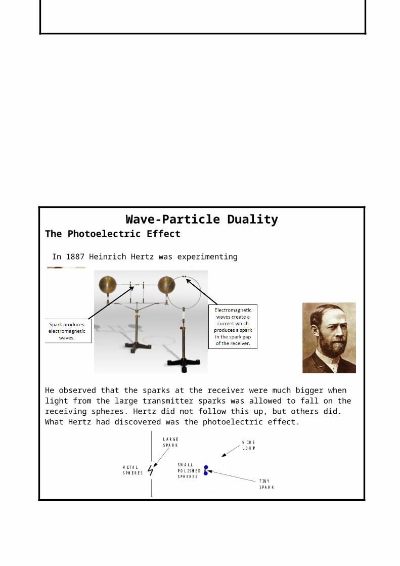
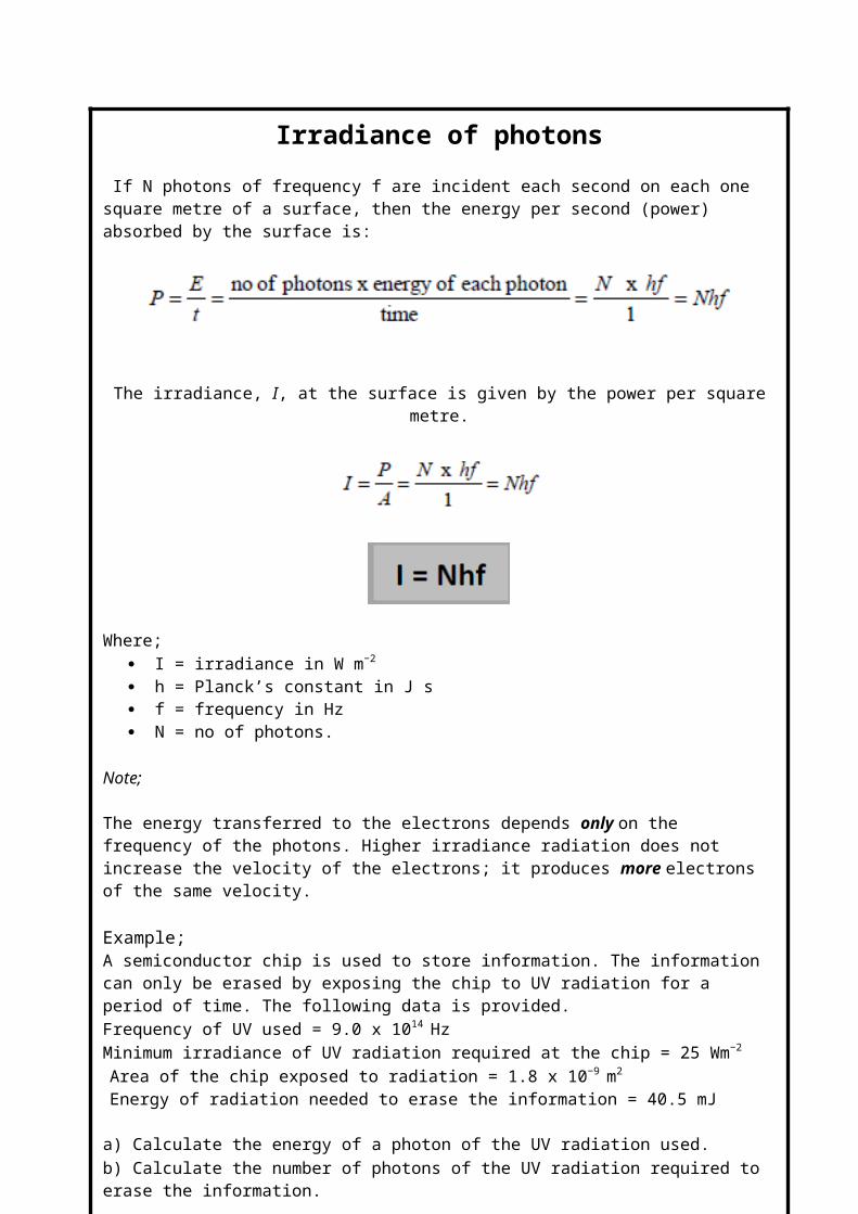
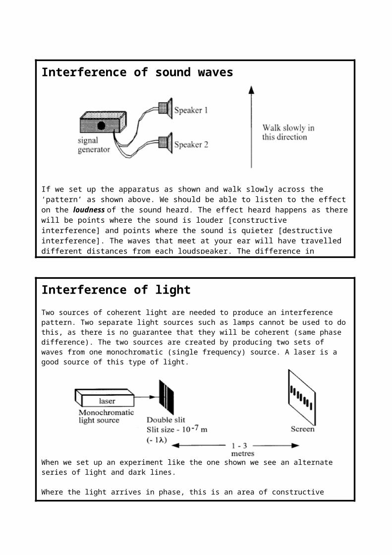
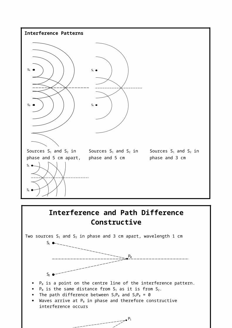
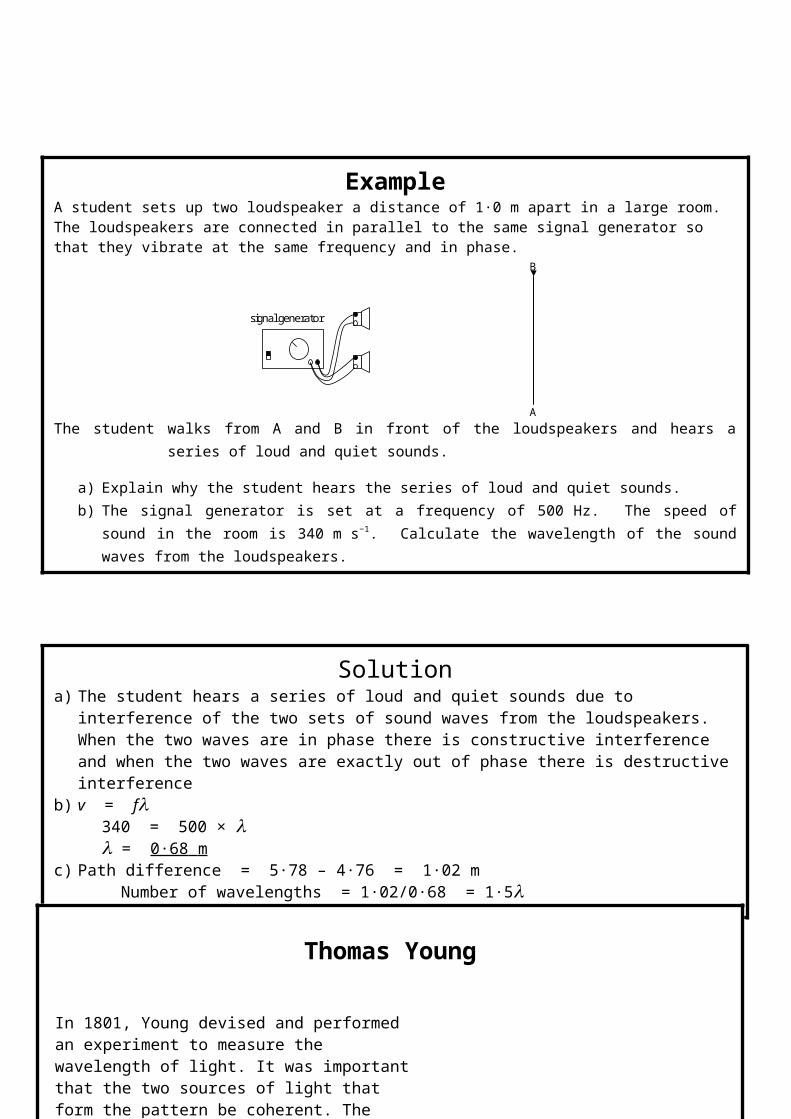
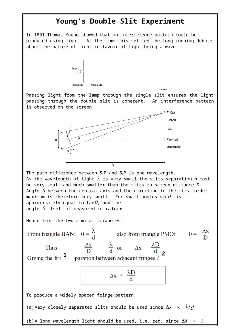