webpages.uidaho.eduwebpages.uidaho.edu/mindworks/competition/resources/2016... · web viewonce the...
TRANSCRIPT

University of Idaho
Haas Mill Tutorialfor
Updated 05/2016 by Carter Drake & Zhengsong Xia

2
Table of Contents
Saving File Format Page 3
Mastercam Startup Page 4
Selecting the Machine Type Page 4
Positioning the Part Page 5
Setting the Origin-Dynamic Xform Page 5
Dynamic Xform Rotation Page 6
Dynamic Xform Translation Page 7
Bounding Box Page 8
Tool Path Page 9
Toolpath Parameters for Drilling Operations Page 10
Animated Preview of Toolpath Operations Page 14
Animation Collision Page 15
Toolpath Parameters for Milling Operations Page 16
Cut Parameters for Finishing Page 18
Depth Parameters for Finishing Page 19
Toolpath Parameters for Pocketing Page 20
Pocketing Alterations Page 26
Toolpath Parameters for Scalloping Page 27
Selecting Proper the Machine, Final Verification, and G1-Code Page 33
Saving the Correct Mastercam File Format using Solidworks1) Open the part file in SolidWorks and select Save As Save as Type IGES file .
- Next, click on the options tab.
3
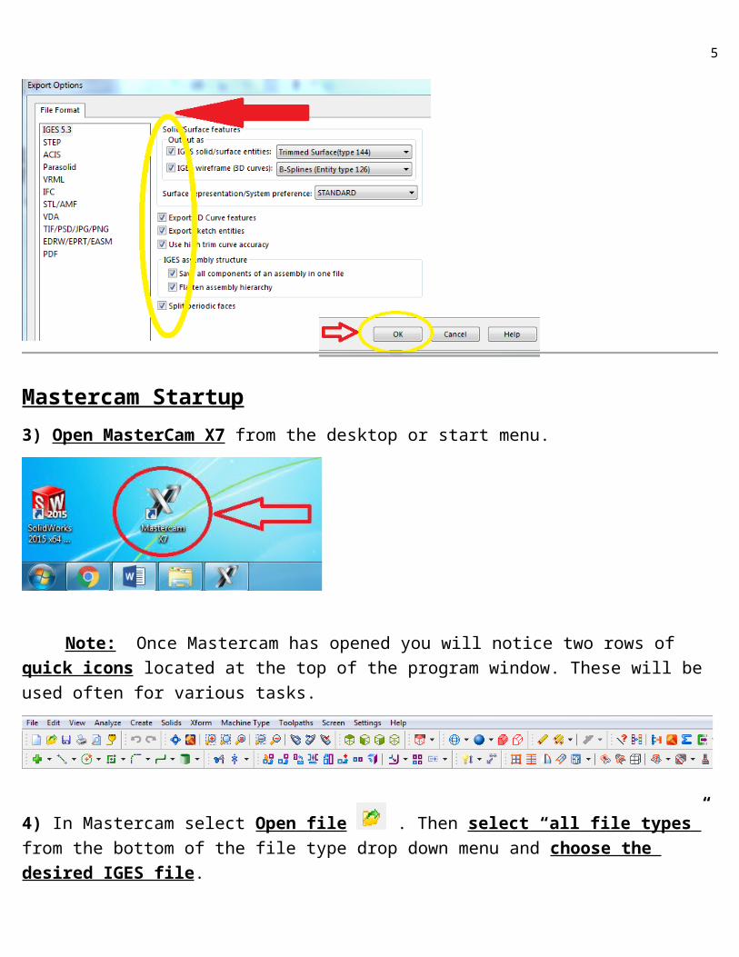
2) Under the Options tab menu select IGES 5.3 on the left and ensure that all boxes are checked unless specified otherwise, especially IGES wireframe (3D curves) and export sketch entities.
- Click OK to confirm settings, then Save.
Mastercam Startup3) Open MasterCam X7 from the desktop or start menu.

4
Note: Once Mastercam has opened you will notice two rows of quick icons located at the top of the program window. These will be used often for various tasks.
4) In Mastercam select Open file . Then select “all file types” from the bottom of the file type drop down menu and choose the desired IGES file.
Selecting the Machine Type5) To select the machine type you will be using for your part go to Machine Type, then Mill. Under the mill header select Default.
Note: Later you will change this to the Haas Mill in the machine shop using a different method.
Positioning the Part
5
6) To position the part to a usable orientation we will use the view tools .
- Tip: Since we will be performing machining operations from above the part, we want to begin by aligning our part with the top view.
7) To properly position the part, first select the shaded view , then isometric view , then
select fit to center the part, and then press the F9 key to display the XYZ axis.
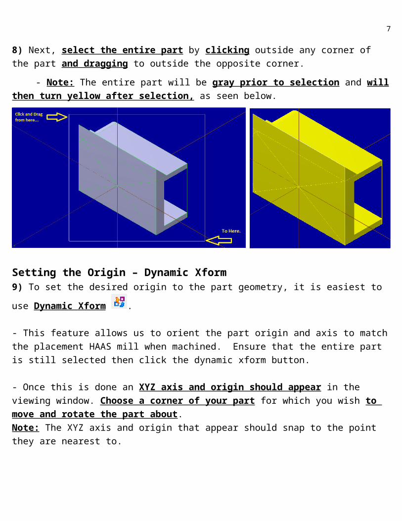
8) Next, select the entire part by clicking outside any corner of the part and dragging to outside the opposite corner.
- Note: The entire part will be gray prior to selection and will then turn yellow after selection, as seen below.
Setting the Origin – Dynamic Xform
9) To set the desired origin to the part geometry, it is easiest to use Dynamic Xform .
- This feature allows us to orient the part origin and axis to match the placement HAAS mill when machined. Ensure that the entire part is still selected then click the dynamic xform button.
- Once this is done an XYZ axis and origin should appear in the viewing window. Choose a corner of your part for which you wish to move and rotate the part about.Note: The XYZ axis and origin that appear should snap to the point they are nearest to.

6
10) To center the corner we just selected with axis origin, click on the point at which all three dynamic Xform axis come together then move it to the universal origin for the part.
- It should snap to the origin when close.
Dynamic Xform Rotation
11) Once the origin is set, you can now rotate the part to move the desired face to the top view.
- Hold the mouse pointer over the X, Y, or Z near the origin, doing so will display a circle with several tick marks in the direction in which the part can be rotated.
- Click on the letter corresponding to the desired direction of rotation. You will then be able to rotate the part.
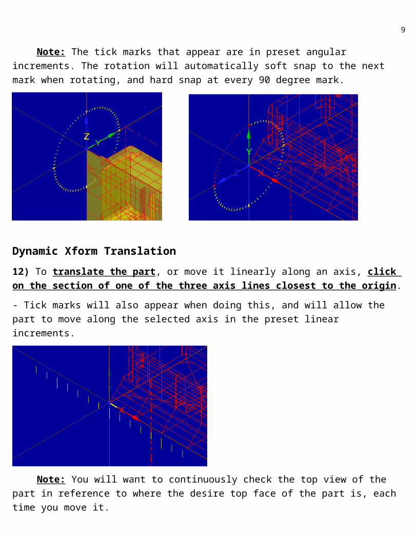
Note: The tick marks that appear are in preset angular increments. The rotation will automatically soft snap to the next mark when rotating, and hard snap at every 90 degree mark.
7
Dynamic Xform Translation
12) To translate the part, or move it linearly along an axis, click on the section of one of the three axis lines closest to the origin.
- Tick marks will also appear when doing this, and will allow the part to move along the selected axis in the preset linear increments.
Note: You will want to continuously check the top view of the part in reference to where the desire top face of the part is, each time you move it.
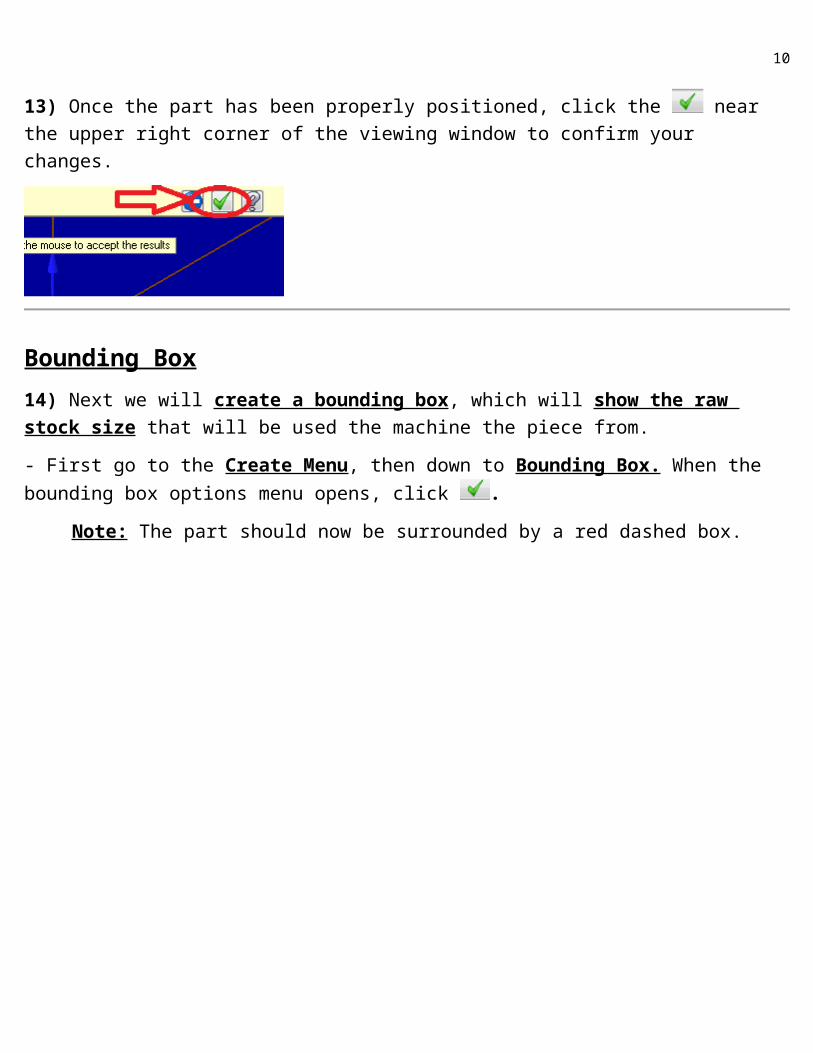
13) Once the part has been properly positioned, click the near the upper right corner of the viewing window to confirm your changes.

8
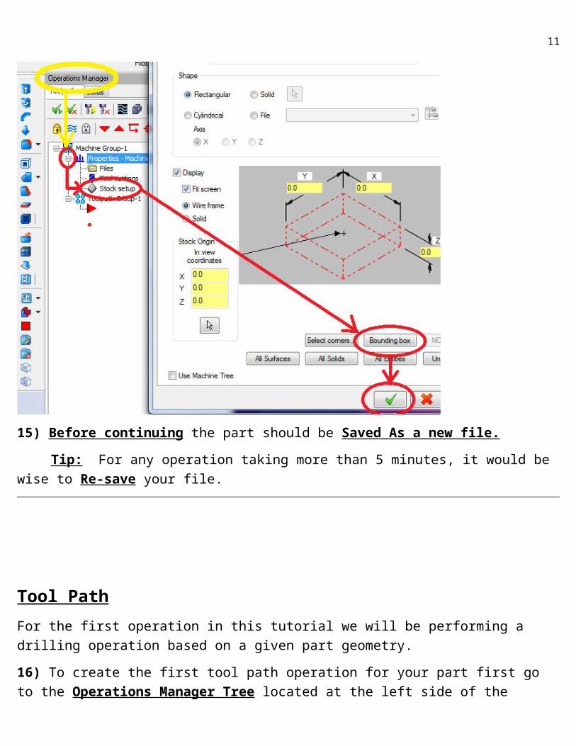
Bounding Box14) Next we will create a bounding box, which will show the raw stock size that will be used the machine the piece from.
- First go to the Create Menu, then down to Bounding Box. When the bounding box options menu opens, click .
Note: The part should now be surrounded by a red dashed box.
15) Before continuing the part should be Saved As a new file.
Tip: For any operation taking more than 5 minutes, it would be wise to Re-save your file.
9
Tool PathFor the first operation in this tutorial we will be performing a drilling operation based on a given part geometry.
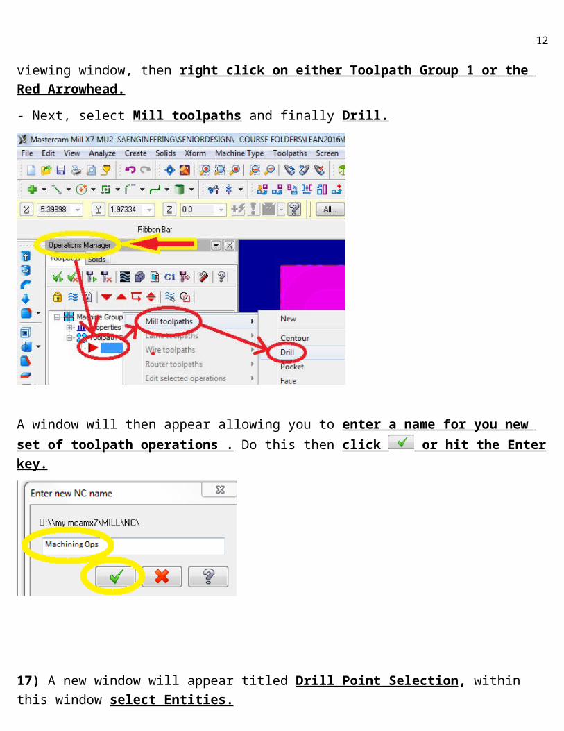
16) To create the first tool path operation for your part first go to the Operations Manager Tree located at the left side of the viewing window, then right click on either Toolpath Group 1 or the Red Arrowhead.
- Next, select Mill toolpaths and finally Drill.
A window will then appear allowing you to enter a name for you new set of toolpath operations . Do this then click or hit the Enter key.
10
17) A new window will appear titled Drill Point Selection, within this window select Entities.
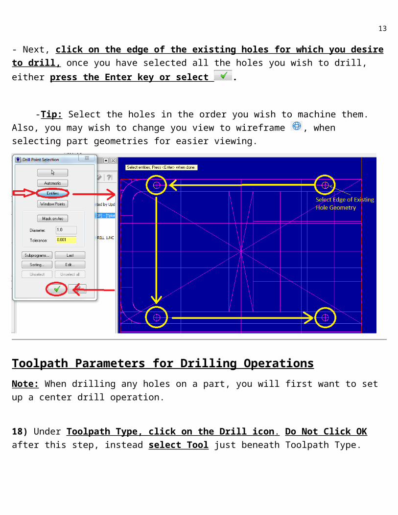
- Next, click on the edge of the existing holes for which you desire to drill, once you have selected all the holes you wish to drill, either press the Enter key or select .
-Tip: Select the holes in the order you wish to machine them. Also, you may wish to change you view to wireframe , when selecting part geometries for easier viewing.
Toolpath Parameters for Drilling OperationsNote: When drilling any holes on a part, you will first want to set up a center drill operation.
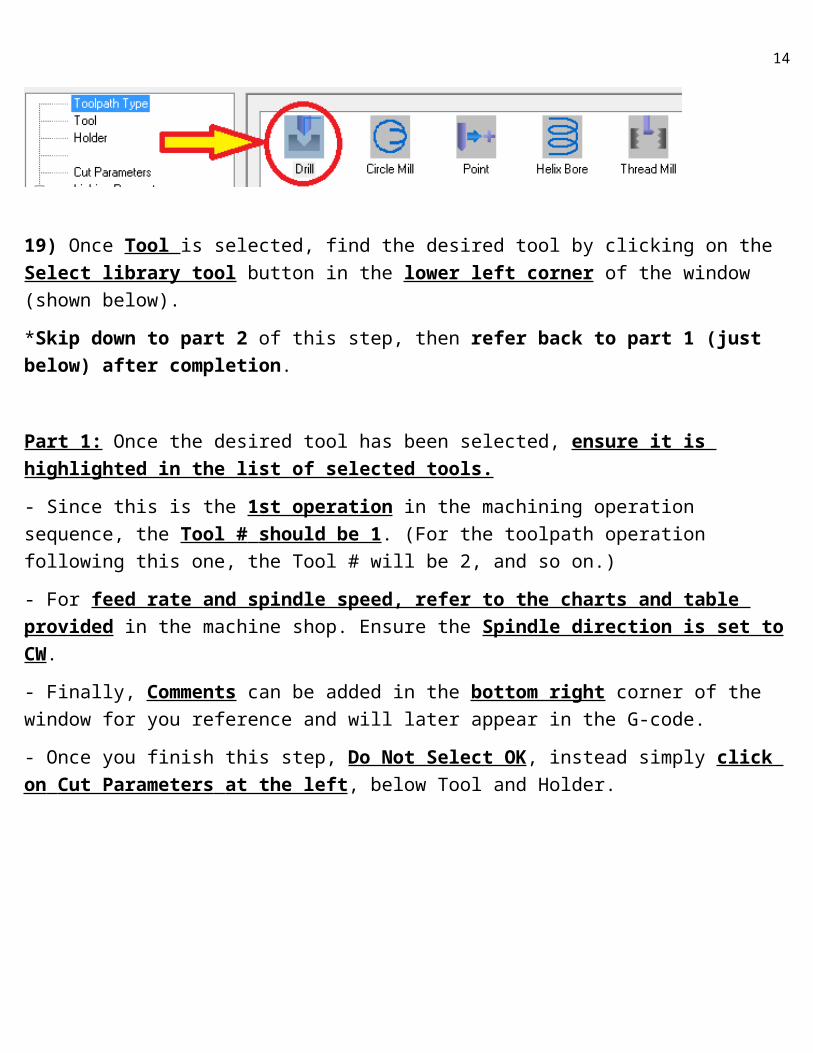
18) Under Toolpath Type, click on the Drill icon . Do Not Click OK after this step, instead select Tool just beneath Toolpath Type.
11
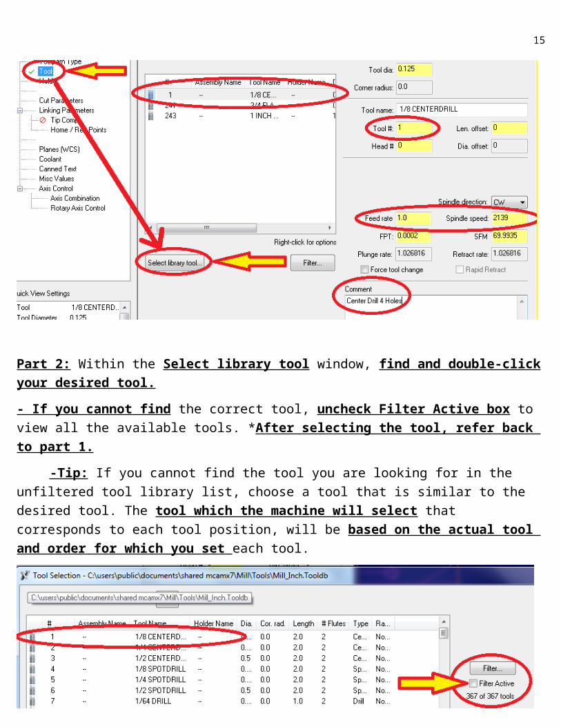
19) Once Tool is selected, find the desired tool by clicking on the Select library tool button in the lower left corner of the window (shown below).
*Skip down to part 2 of this step, then refer back to part 1 (just below) after completion.
Part 1: Once the desired tool has been selected, ensure it is highlighted in the list of selected tools.
- Since this is the 1st operation in the machining operation sequence, the Tool # should be 1 . (For the toolpath operation following this one, the Tool # will be 2, and so on.)
- For feed rate and spindle speed, refer to the charts and table provided in the machine shop. Ensure the Spindle direction is set to CW.
- Finally, Comments can be added in the bottom right corner of the window for you reference and will later appear in the G-code.
- Once you finish this step, Do Not Select OK, instead simply click on Cut Parameters at the left , below Tool and Holder.
Part 2: Within the Select library tool window, find and double-click your desired tool.
- If you cannot find the correct tool, uncheck Filter Active box to view all the available tools. *After selecting the tool, refer back to part 1.
12
-Tip: If you cannot find the tool you are looking for in the unfiltered tool library list, choose a tool that is similar to the desired tool. The tool which the machine will select that corresponds to each tool position, will be based on the actual tool and order for which you set each tool.
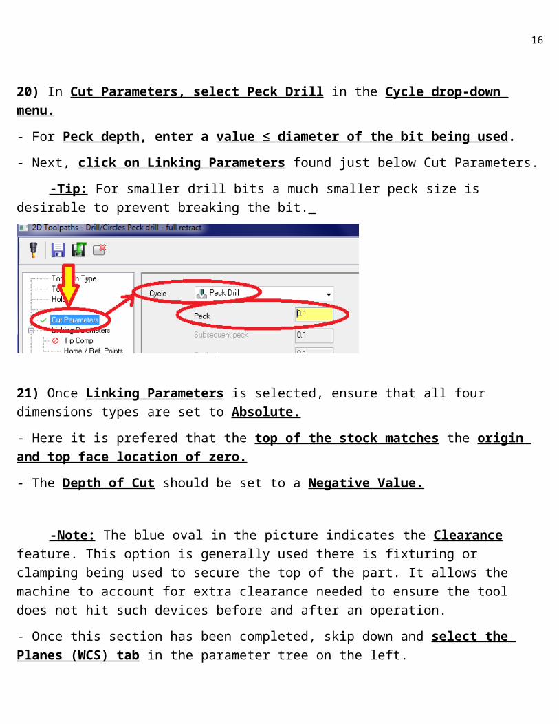
20) In Cut Parameters, select Peck Drill in the Cycle drop-down menu.
- For Peck depth, enter a value ≤ diameter of the bit being used.
- Next, click on Linking Parameters found just below Cut Parameters.
-Tip: For smaller drill bits a much smaller peck size is desirable to prevent breaking the bit.
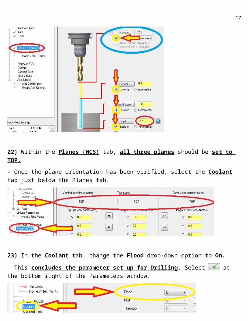
21) Once Linking Parameters is selected, ensure that all four dimensions types are set to Absolute.
- Here it is prefered that the top of the stock matches the origin and top face location of zero.
- The Depth of Cut should be set to a Negative Value.
-Note: The blue oval in the picture indicates the Clearance feature. This option is generally used there is fixturing or clamping being used to secure the top of the part. It allows the machine to account for extra clearance needed to ensure the tool does not hit such devices before and after an operation.
13
- Once this section has been completed, skip down and select the Planes (WCS) tab in the parameter tree on the left.
22) Within the Planes (WCS) tab, all three planes should be set to TOP.
- Once the plane orientation has been verified, select the Coolant tab just below the Planes tab.
23) In the Coolant tab, change the Flood drop-down option to On.
- This concludes the parameter set up for Drilling. Select at the bottom right of the Parameters window.
14
Animated Preview of Toolpath Operations24) Before you can view the newly created toolpath operations you must first regenerate all toolpaths.
- To do this go to the Operations Manager Tree on the left. At the top of the Operations Manager, first click the Select all operations button. Next, click Regenerate all selected operations.
- Once these two steps have been completed you have two options available for visualizing the newly created toolpath.
- The first option is to preview all toolpaths at once in consecutive order. Following the first two steps click the Verify selected options button denoted by a gray block figure at the top of the Operations Manager. (Bottom left picture)
- The second option is to preview one toolpath by itself. Following the first two steps right-click on the toolpath for the specific desired toolpath operation. (Bottom right picture)
About Toolpath Animations
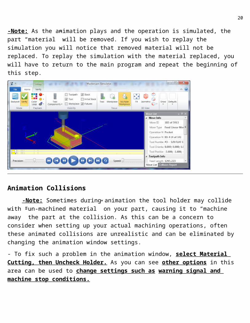
A new window will appear with VCR-like controls. Before pressing play, rotate the view to the desired orientation then reduce the play speed to the lowest setting. (You can increase the speed to a more desirable setting after the animation has started. Press the play button to animate the toolpath.
When you press play, you should see the mill performing the machining operations you specified on the stock for which your part was modeled. It should look just as you would expect it to if you were actually machining the part. A yellow surface indicates a cut. A red surface indicates a collision.
15
If red appears by the end of the simulation, your tool settings need to be adjusted. Select to exit the Verify dialog box.
-Note: As the animation plays and the operation is simulated, the part “material” will be removed. If you wish to replay the simulation you will notice that removed material will not be replaced. To replay the simulation with the material replaced, you will have to return to the main program and repeat the beginning of this step.
Animation Collisions
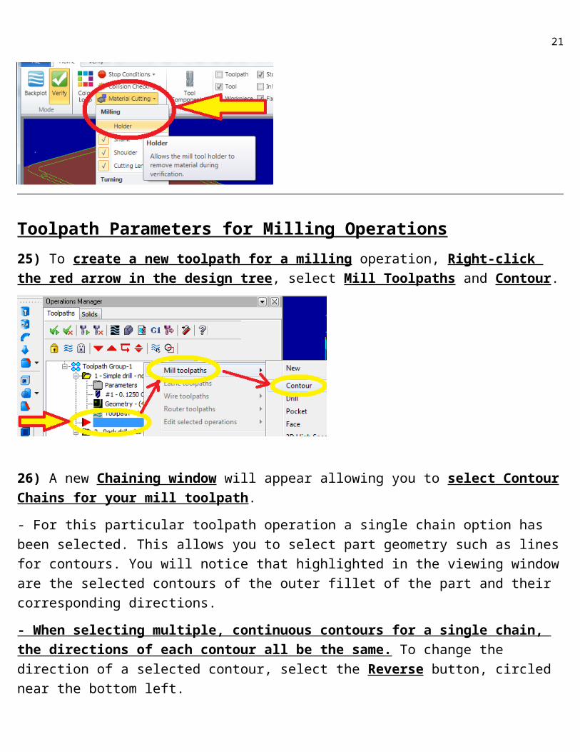
-Note: Sometimes during animation the tool holder may collide with “un-machined material” on your part, causing it to “machine away” the part at the collision. As this can be a concern to consider when setting up your actual machining operations, often these animated collisions are unrealistic and can be eliminated by changing the animation window settings.
- To fix such a problem in the animation window, select Material Cutting, then Uncheck Holder. As you can see other options in this area can be used to change settings such as warning signal and machine stop conditions.
16
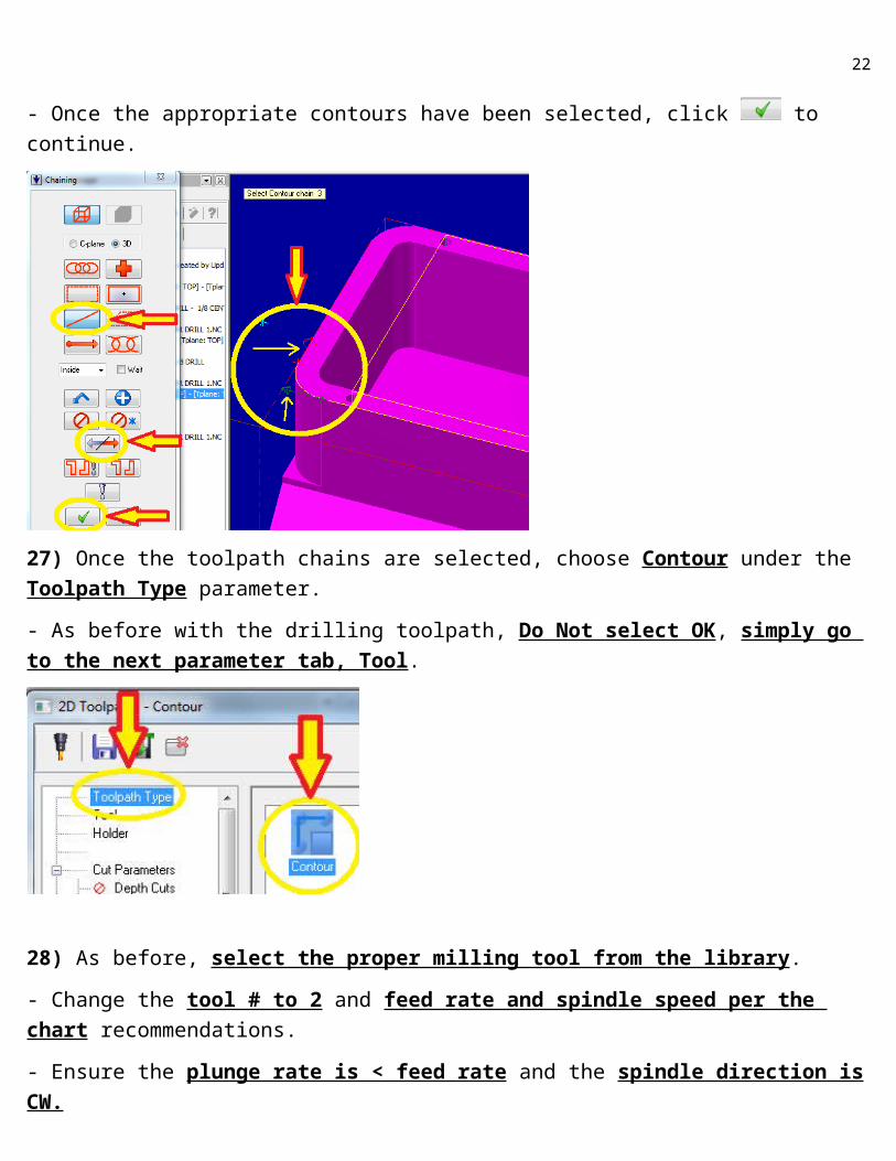
Toolpath Parameters for Milling Operations25) To create a new toolpath for a milling operation, Right-click the red arrow in the design tree, select Mill Toolpaths and Contour.
26) A new Chaining window will appear allowing you to select Contour Chains for your mill toolpath.
- For this particular toolpath operation a single chain option has been selected. This allows you to select part geometry such as lines for contours. You will notice that highlighted in the viewing window are the selected contours of the outer fillet of the part and their corresponding directions.
- When selecting multiple, continuous contours for a single chain, the directions of each contour all be the same. To change the direction of a selected contour, select the Reverse button, circled near the bottom left.
- Once the appropriate contours have been selected, click to continue.
17
27) Once the toolpath chains are selected, choose Contour under the Toolpath Type parameter.
- As before with the drilling toolpath, Do Not select OK, simply go to the next parameter tab, Tool.
28) As before, select the proper milling tool from the library.
- Change the tool # to 2 and feed rate and spindle speed per the chart recommendations.
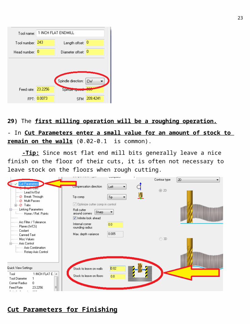
- Ensure the plunge rate is < feed rate and the spindle direction is CW.
29) The first milling operation will be a roughing operation.
- In Cut Parameters enter a small value for an amount of stock to remain on the walls (0.02-0.1” is common).
-Tip: Since most flat end mill bits generally leave a nice finish on the floor of their cuts, it is often not necessary to leave stock on the floors when rough cutting.

18
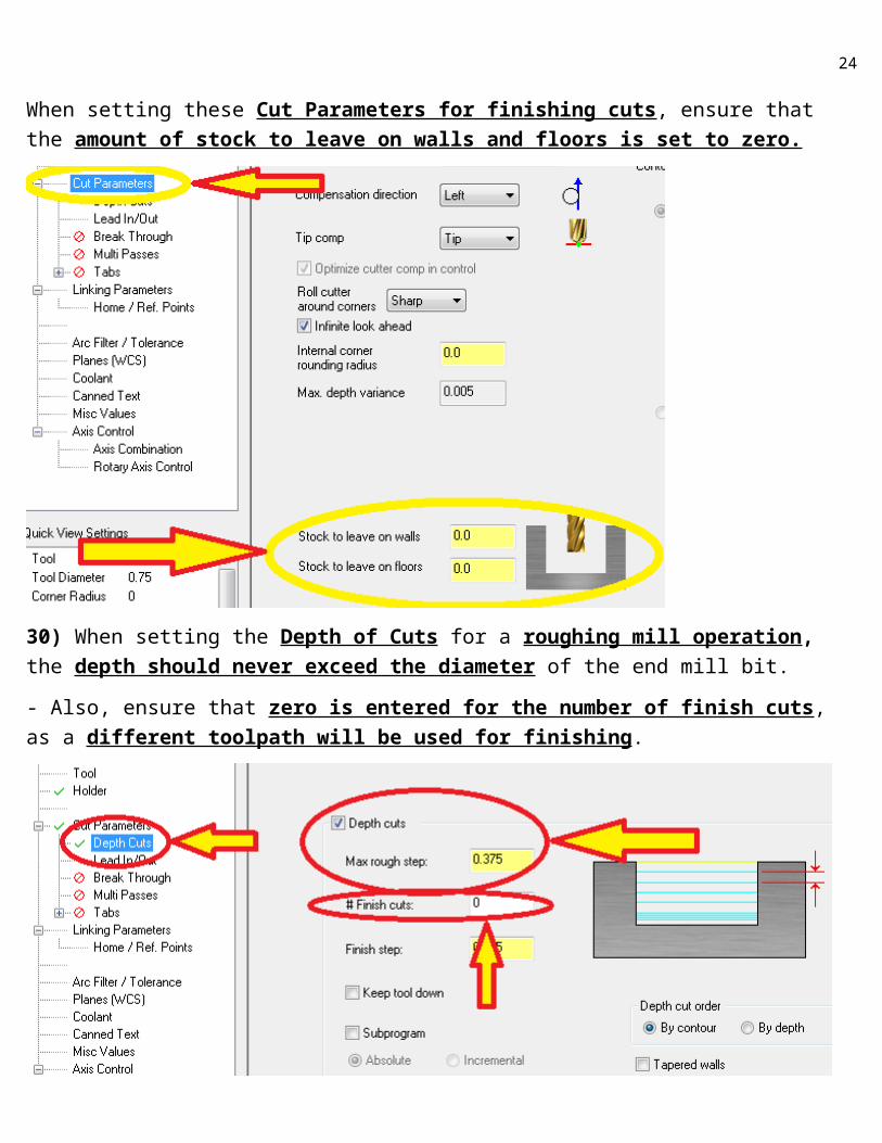
Cut Parameters for Finishing
When setting these Cut Parameters for finishing cuts, ensure that the amount of stock to leave on walls and floors is set to zero.

19
30) When setting the Depth of Cuts for a roughing mill operation, the depth should never exceed the diameter of the end mill bit.
- Also, ensure that zero is entered for the number of finish cuts, as a different toolpath will be used for finishing.
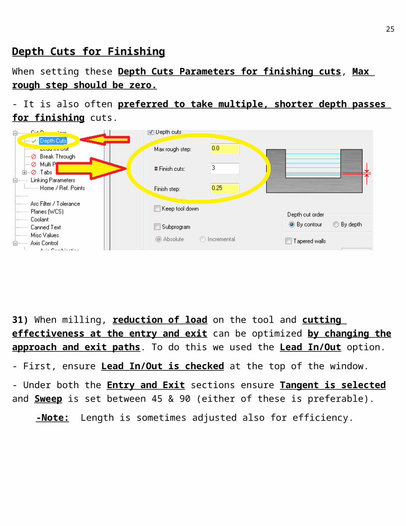
Depth Cuts for Finishing
When setting these Depth Cuts Parameters for finishing cuts, Max rough step should be zero.
- It is also often preferred to take multiple, shorter depth passes for finishing cuts.
20
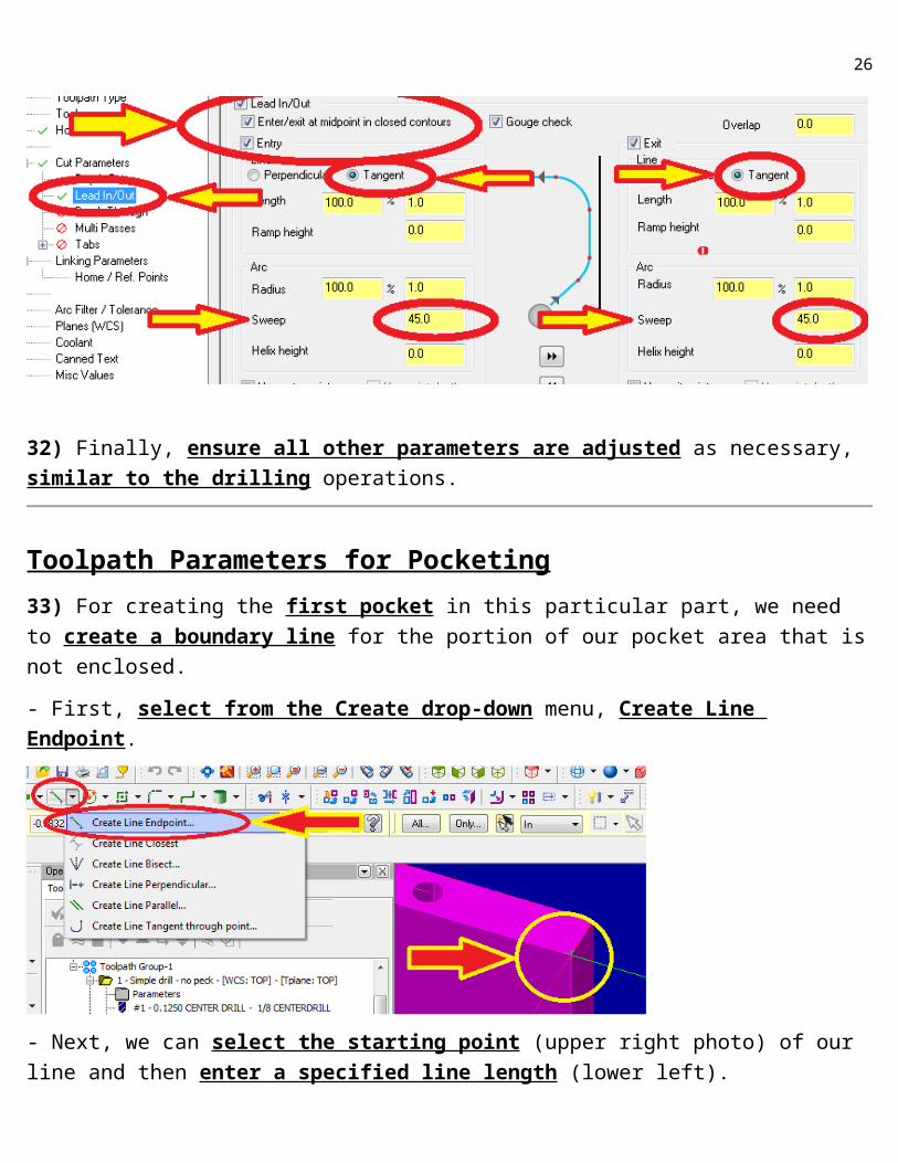
31) When milling, reduction of load on the tool and cutting effectiveness at the entry and exit can be optimized by changing the approach and exit paths. To do this we used the Lead In/Out option.
- First, ensure Lead In/Out is checked at the top of the window.
- Under both the Entry and Exit sections ensure Tangent is selected and Sweep is set between 45 & 90 (either of these is preferable).
-Note: Length is sometimes adjusted also for efficiency.
32) Finally, ensure all other parameters are adjusted as necessary, similar to the drilling operations.
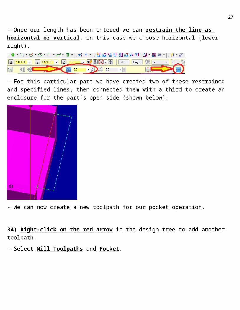
Toolpath Parameters for Pocketing33) For creating the first pocket in this particular part, we need to create a boundary line for the portion of our pocket area that is not enclosed.
- First, select from the Create drop-down menu, Create Line Endpoint.
21
- Next, we can select the starting point (upper right photo) of our line and then enter a specified line length (lower left).
- Once our length has been entered we can restrain the line as horizontal or vertical, in this case we choose horizontal (lower right).
- For this particular part we have created two of these restrained and specified lines, then connected them with a third to create an enclosure for the part’s open side (shown below).
- We can now create a new toolpath for our pocket operation.
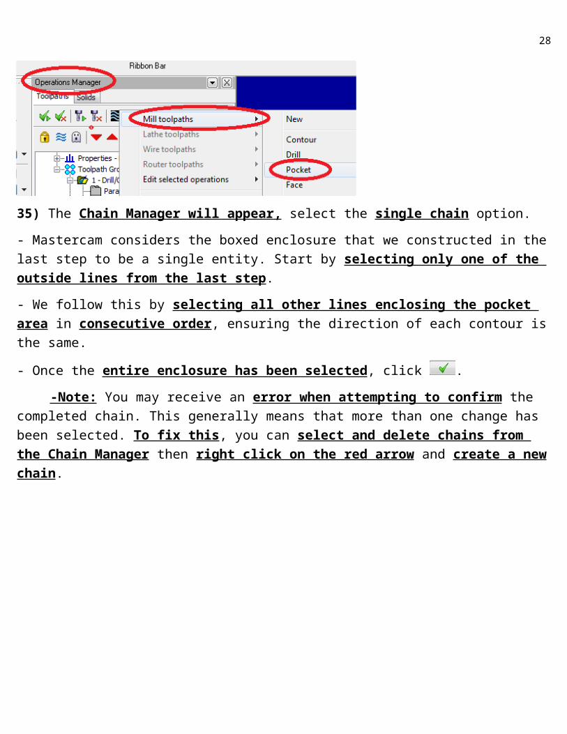
34) Right-click on the red arrow in the design tree to add another toolpath.
- Select Mill Toolpaths and Pocket.
22
35) The Chain Manager will appear, select the single chain option.
- Mastercam considers the boxed enclosure that we constructed in the last step to be a single entity. Start by selecting only one of the outside lines from the last step.
- We follow this by selecting all other lines enclosing the pocket area in consecutive order, ensuring the direction of each contour is the same.
- Once the entire enclosure has been selected, click .
-Note: You may receive an error when attempting to confirm the completed chain. This generally means that more than one change has been selected. To fix this, you can select and delete chains from the Chain Manager then right click on the red arrow and create a new chain.
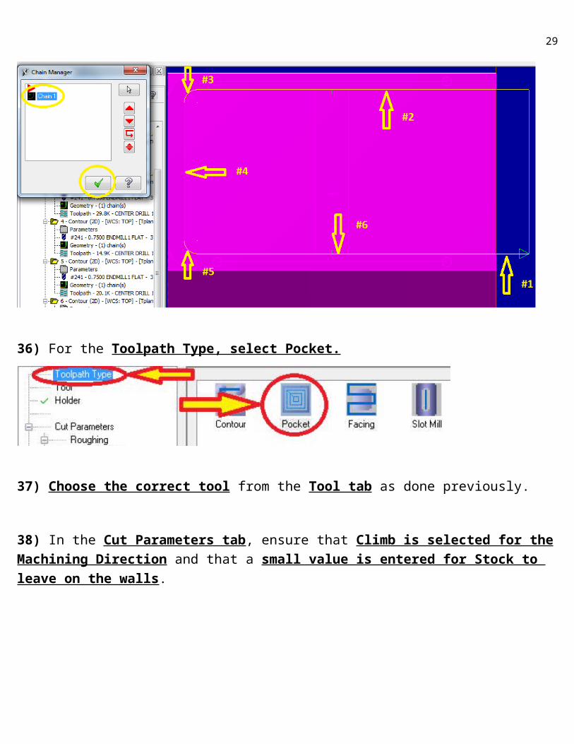
36) For the Toolpath Type, select Pocket.
37) Choose the correct tool from the Tool tab as done previously.
23
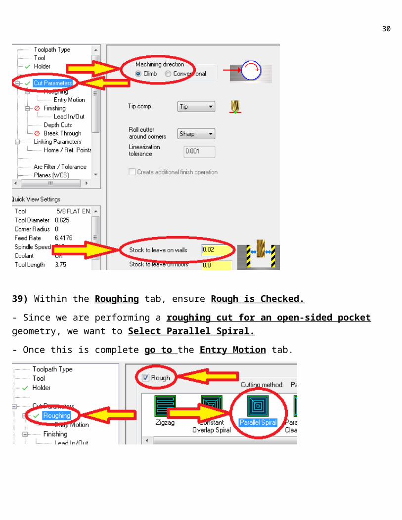
38) In the Cut Parameters tab, ensure that Climb is selected for the Machining Direction and that a small value is entered for Stock to leave on the walls.
39) Within the Roughing tab, ensure Rough is Checked.
- Since we are performing a roughing cut for an open-sided pocket geometry, we want to Select Parallel Spiral.
- Once this is complete go to the Entry Motion tab.
24
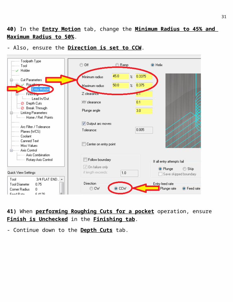
40) In the Entry Motion tab, change the Minimum Radius to 45% and Maximum Radius to 50%.
- Also, ensure the Direction is set to CCW.
41) When performing Roughing Cuts for a pocket operation, ensure Finish is Unchecked in the Finishing tab.
- Continue down to the Depth Cuts tab.
25
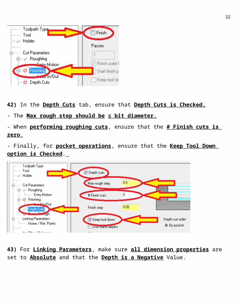
42) In the Depth Cuts tab, ensure that Depth Cuts is Checked.
- The Max rough step should be ≤ bit diameter.
- When performing roughing cuts, ensure that the # Finish cuts is zero .
- Finally, for pocket operations, ensure that the Keep Tool Down option is Checked.
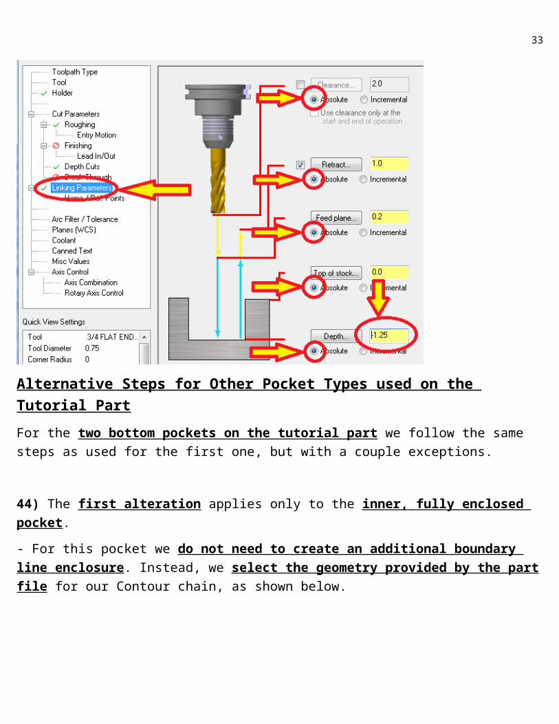
43) For Linking Parameters, make sure all dimension properties are set to Absolute and that the Depth is a Negative Value.
26
Alternative Steps for Other Pocket Types used on the Tutorial Part
For the two bottom pockets on the tutorial part we follow the same steps as used for the first one, but with a couple exceptions.
44) The first alteration applies only to the inner, fully enclosed pocket .
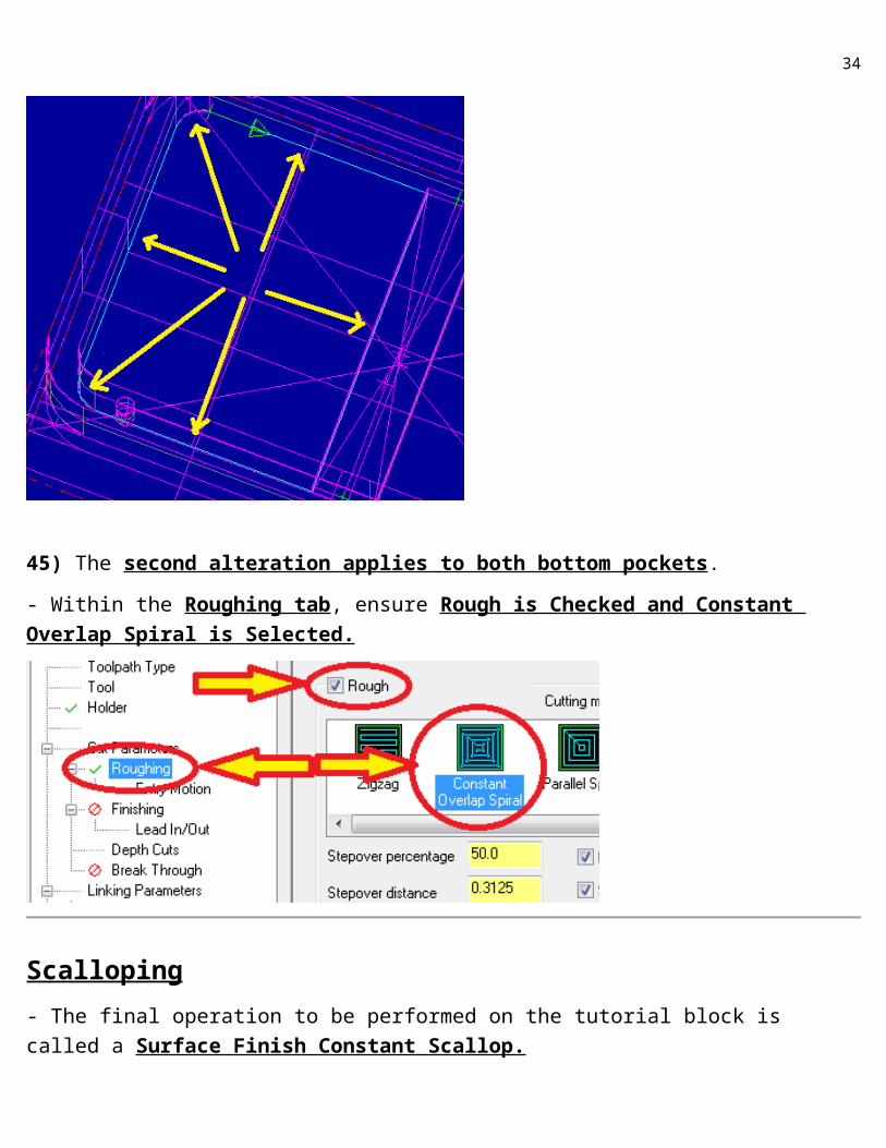
- For this pocket we do not need to create an additional boundary line enclosure. Instead, we select the geometry provided by the part file for our Contour chain, as shown below.
45) The second alteration applies to both bottom pockets.
- Within the Roughing tab, ensure Rough is Checked and Constant Overlap Spiral is Selected.
27
Scalloping- The final operation to be performed on the tutorial block is called a Surface Finish Constant Scallop.
- Here we are essentially machining a squared, block edge down to an angled surface using a ball-nosed end mill.
- For this process the endmill either begins near the outside boundary making cuts around the perimeter while moving inward, or begins in the center and moves outward, until all the desired material is removed.
-Tip: One thing to consider when performing this operation is that the larger the ball-nosed end mill bit is, the less “scallops or ridges” will remain after the operation, however, this will also prevent the endmill from being able to make more precise cuts near the top of the ramped section.
46) To begin this operation it is desirable to make a containment boudary extruding past the desired machine surface. If this is not done the rounded geometry of the milling bit will leave material at the machine surface edges.
- Select the create line endpoint button as done in the pocketing operations. As before, restrict the length of the line to ≥ bit diameter (0.5 in this case), and restrict the line to horizontal as shown below.
- After completing each line select the Apply Button , prior to continuing to the next line. This allows you to add new lines without exiting the create line toolbar.
28
47) Next, create two additional boundary lines that follow the geometry of the ramp edge.
- First select the side view profile button which allows us to better see the ramp profile.
- While still in the Create line endpoint toolbar, create a temporary line from the top corner of the ramp to the bottom corner which follows its edge as shown below.
- Note the angle of the line for the next step.
48) Return to isometric view. Select Create line endpoint if not already in the toolbar.
- Create a line, start it at the end of one of the first two lines and end it in the general area where you want it to be.
-Note: Ensure that horizontal has been turned off for this step.
- Once this has been done, enter both the desired distance and the angle from the previous step to set it in place.
29
49) To create an equal duplicate of the previous line for the other side, select Create Line Parallel from the Create Line drop-down.
- Select a line message will appear, select the previously created line.
- Next, a Select the point to place a parallel line through message will appear. Select the endpoint of the other initial horizontal line we created, and the new line will appear. Click the Apply button as before.
50) To finish our scalloping boundary, create a new line stretching between the two endpoints of the previously created lines.
30
51) Right click on the red arrow in the design tree.
- Select Mill toolpaths, Surface finish, then Scallop.
52) A message will appear stating Select Drive Surfaces.
- Select the desired surface for the machining operation.
31
53) The Toolpath/surface selection window should appear. You can see that the Drive surface has already been selected as there is a (1) next to it.
- Select the arrow button under the Containment boundary heading.
Notice the (0) under this heading as well because although the boundary has been created it has not yet been selected.
54) When the Chaining window appears, simply go around the containment boundary selecting each line. Ensure all contour directions are the same.
- Once the containment boundary has been selected click . In the Toolpath/surface selection window (shown in the previous step), there should now be a (1) below the Containment boundary heading. Select to continue.
- The contour direction, denoted by red or green arrows, is shown circled in the picture below.
32
55) The Surface Finish Constant Scallop window should now appear.
- Within Toolpath parameters, Open the tool library and select the desired ball endmill.
- Ensure Spindle direction is set to CW. Set the speed, feed, and plunge rates accordingly.
- Select the Coolant tab and turn Flood On.
- Click on the Surface Parameters tab at the top of the window.
56) Within the Surface Parameters tab, ensure the Tool Containment is set to Inside. This will prevent unwanted loss of material outside the containment boundary.
- Click to complete the scalloping parameter setup.
33
Selecting the Proper Machine, Final Verification, and G1-Code57) Save all changes.
58) Expand the Properties menu in the Operations Manager and select Files then Replace.
- A list of Machines will appear. Select HAAS MILL from the list then click Open.
-Note: HAAS MILL will only appear on the list when on the computers in the machine shop.
59) Select and regenerate all toolpaths in the operations manager.
60) Verify (animate and view) the entire machining process to check that all operations are satisfactory.
61) From the Operations manager, select the G1 button.
- A Post processing window will appear, click .
34
62) A Save as window will appear.
- Save the file for your G1 code with a new name and location.
63) The Mastercam Code Expert loading screen will appear.
35
64) Finally, the new G1 code will appear in a code edito r window.
- IMPORTANT: The new code will only be accurate for the machine you will be using if the correct machine was chosen in step 58! If you are unsure of this, ask the shop manager or a mentor.