eprints.soton.ac.uk · web viewdemonstration of arbitrary temporal shaping of picosecond pulses in...
TRANSCRIPT

Demonstration of arbitrary temporal shaping of picosecond pulses in a radially polarized Yb-fiber MOPA with > 10 W average powerBETTY MENG ZHANG,1, 2 YUJUN FENG,1,3 DI LIN,1, * JONATHAN H. V. PRICE,1 JOHAN NILSSON,1 SHAIFUL ALAM,1 PERRY PING SHUM,2 DAVID NEIL PAYNE,1 AND DAVID J. RICHARDSON1
1Optoelectronics Research Centre, University of Southampton, Southampton SO17 1BJ, UK2School of Electrical and Electronic Engineering, Nanyang Technological University, Singapore 639798, Singapore3Department of Engineering Physics, Tsinghua University, Beijing 100084, China*[email protected]
Abstract: High precision surface processing has an unmet demand for picosecond pulses with arbitrary temporal profiles in radial polarization states and at high average powers. Here, simultaneous spatial and arbitrary temporal shaping of chirped 10 – 100 picoseconds pulses is demonstrated with an Yb-doped fiber laser system generating an output power of more than 10 W at 40 MHz repetition frequency. The closed-loop control algorithm carves the pulses using a commercial, rugged, and fiberized optical pulse shaper placed at the front end of the system and uses feedback from the output pulse shapes for optimization. Arbitrary complex temporal profiles were demonstrated using a dispersive Fourier transform based technique and limits set by the system were investigated. Pulse shaping in the spatial domain was accomplished using an S-waveplate, fabricated in-house, to change the linearly polarized fundamental mode into a doughnut mode with radial polarization. This was amplified in a final-stage few-mode large-mode area fiber amplifier. Placing both temporal and spatial shaping elements before the power-amplifier avoids complex and potentially lossy conversion of the spatial mode profile at the output and provides an efficient route for power-scaling. The use of properly oriented quarter- and half-wave plates, which have both low loss and high power handling capability, enabled the output to be set to pure radial or azimuthal polarization states. Using commercial off-the-shelf components, our technique is able to immediately enhance the versatility of ultrashort fiber laser systems for high precision material processing and other industrial applications. © 2017 Optical Society of America
OCIS codes: (140.3070) Infrared and far-infrared lasers; (140.3300) Laser beam shaping; (140.3390) Laser materials processing; (140.3510) Lasers, fiber; (140.3538) Lasers, pulsed; (140.7090) Ultrafast lasers.
References and links1. B. M. Zhang, Y. Lai, W. Yuan, Y. P. Seah, P. P. Shum, X. Yu, and H. Wei, "Laser-assisted lateral optical fiber
processing for selective infiltration," Opt. Express 22, 2675-2680 (2014).2. A. G. Demir, K. Pangovski, W. O’Neill, and B. Previtali, "Laser micromachining of TiN coatings with variable
pulse durations and shapes in ns regime," Surf. Coat. Technol. 258, 240-248 (2014).3. B. M. Zhang, M. Liu, P. P. Shum, X. Li, and X. Cheng, "Design and fabrication of 100 kW peak power
picosecond fiber laser for efficient laser marking and drilling," in IEEE Photonics Conference, 2015, 70-71.4. M. Liu, B. M. Zhang, P. P. Shum, and X. Cheng, "Nanosecond Pulse Fiber Laser Blackening of Aluminum
Alloy With Alumina Surface," IEEE Photon. Technol. Lett. 28, 2701-2704 (2016).5. D. J. Richardson, J. Nilsson, and W. A. Clarkson, "High power fiber lasers: current status and future
perspectives [Invited]," J. Opt. Soc. Am. B 27, B63-B92 (2010).6. K. Pangovski, M. Sparkes, A. Cockburn, O. W, O'Neill, P. S. Teh, D. Lin, and D. Richardson, "Control of
Material Transport Through Pulse Shape Manipulation—A Development Toward Designer Pulses," IEEE J. Sel. Topics Quantum Electron. 20, 51-63 (2014).
7. R. Le Harzic, D. Breitling, S. Sommer, C. Föhl, K. König, F. Dausinger, and E. Audouard, "Processing of metals by double pulses with short laser pulses," Appl. Phys. A 81, 1121-1125 (2005).

8. D. Lin, N. Baktash, M. Berendt, M. Beresna, P. G. Kazansky, W. A. Clarkson, S. U. Alam, and D. J. Richardson, "Radially and azimuthally polarized nanosecond Yb-doped fiber MOPA system incorporating temporal shaping," Opt. Lett. 42, 1740-1743 (2017).
9. X. D. Wang, A. Michalowski, D. Walter, S. Sommer, M. Kraus, J. S. Liu, and F. Dausinger, "Laser drilling of stainless steel with nanosecond double-pulse," Opt. & Laser Technol. 41, 148-153 (2009).
10. A. M. Weiner, "Femtosecond pulse shaping using spatial light modulators," Rev. Sci. Instrum. 71, 1929-1960 (2000).
11. P. Petropoulos, M. Ibsen, A. D. Ellis, and D. J. Richardson, "Rectangular Pulse Generation Based on Pulse Reshaping Using a Superstructured Fiber Bragg Grating," J. Lightwave Technol. 19, 746 (2001).
12. J. Azaña, L. K. Oxenløwe, E. Palushani, R. Slavík, M. Galili, H. C. H. Mulvad, H. Hu, Y. Park, A. T. Clausen, and P. Jeppesen, "In-Fiber Subpicosecond Pulse Shaping for Nonlinear Optical Telecommunication Data Processing at 640 Gbit/s," Int. J. Opt. 2012, 1-16 (2012).
13. C. Guo, M. Nix, S. S. H. Yam, and S. He, "Picosecond and Sub-Picosecond Flat-Top Pulse Shaping Using Abrupt Taper Interferometers," J. Lightwave Technol. 28, 876-881 (2010).
14. Y. Park, M. H. Asghari, T.-J. Ahn, and J. Azaña, "Transform-limited picosecond pulse shaping based on temporal coherence synthesization," Opt. Express 15, 9584-9599 (2007).
15. A. M. Weiner and J. P. Heritage, "Picosecond and femtosecond Fourier pulse shape synthesis," Rev. Phys. Appl. 22, 1619-1628 (1987).
16. M. Kraus, M. A. Ahmed, A. Michalowski, A. Voss, R. Weber, and T. Graf, "Microdrilling in steel using ultrashort pulsed laser beams with radial and azimuthal polarization," Opt. Express 18, 22305-22313 (2010).
17. H. K. Tönshoff, C. Momma, A. Ostendorf, S. Nolte, and G. Kamlage, "Microdrilling of metals with ultrashort laser pulses," J. Laser Appl. 12, 23-27 (2000).
18. V. G. Niziev and A. V. Nesterov, "Influence of beam polarization on laser cutting efficiency," J. Phys. D: Appl. Phys. 32, 1455 (1999).
19. M. Meier, V. Romano, and T. Feurer, "Material processing with pulsed radially and azimuthally polarized laser radiation," Appl. Phys. A 86, 329-334 (2007).
20. O. J. Allegre, W. Perrie, S. P. Edwardson, G. Dearden, and K. G. Watkins, "Laser microprocessing of steel with radially and azimuthally polarized femtosecond vortex pulses," J. Opt. 14, 085601 (2012).
21. D. Lin, S. U. Alam, A. Malinowski, K. K. Chen, J. R. Hayes, J. C. Flannagan, V. Geddes, J. Nilsson, S. Ingram, S. Norman, and D. J. Richardson, "Temporally and spatially shaped fully-fiberized ytterbium-doped pulsed MOPA," Laser Phys. Lett. 8, 747 (2011).
22. D. Lin, K. Xia, R. Li, X. Li, G. Li, K.-i. Ueda, and J. Li, "Radially polarized and passively Q-switched fiber laser," Opt. Lett. 35, 3574-3576 (2010).
23. D. Lin, J. M. O. Daniel, M. Gecevičius, M. Beresna, P. G. Kazansky, and W. A. Clarkson, "Cladding-pumped ytterbium-doped fiber laser with radially polarized output," Opt. Lett. 39, 5359-5361 (2014).
24. S. Kanazawa, Y. Kozawa, and S. Sato, "High-power and highly efficient amplification of a radially polarized beam using an Yb-doped double-clad fiber," Opt. Lett. 39, 2857-2859 (2014).
25. D. Lin, K. Xia, J. Li, R. Li, K.-i. Ueda, G. Li, and X. Li, "Efficient, high-power, and radially polarized fiber laser," Opt. Lett. 35, 2290-2292 (2010).
26. B. M. Zhang, Y. Feng, D. Lin, J. Price, S. Alam, J. Nilsson, P. Shum, D. Payne, and D. Richardson, "Radially polarised Yb-fiber MOPA producing 10 W output using SLM based pulse shaping for efficient generation of arbitrary shaped picosecond pulses," in Lasers Congress 2016 (ASSL, LSC, LAC), ATh3A.3.
27. J. Prawiharjo, N. K. Daga, R. Geng, J. H. Price, D. C. Hanna, D. J. Richardson, and D. P. Shepherd, "High fidelity femtosecond pulses from an ultrafast fiber laser system via adaptive amplitude and phase pre-shaping," Opt. Express 16, 15074-15089 (2008).
28. A. M. Weiner, "Ultrafast optical pulse shaping: A tutorial review," Opt. Commun. 284, 3669-3692 (2011).29. Y. Xin, D. J. Richardson, and P. Petropoulos, "Broadband, Flat Frequency Comb Generated Using Pulse
Shaping-Assisted Nonlinear Spectral Broadening," IEEE Photon. Technol. Lett. 25, 543-545 (2013).30. J. Azana and M. A. Muriel, "Real-time optical spectrum analysis based on the time-space duality in chirped
fiber gratings," IEEE J. Quantum Electron. 36, 517-526 (2000).31. B. H. Kolner, "Space-time duality and the theory of temporal imaging," IEEE J. Quantum Electron. 30, 1951-
1963 (1994).32. M. Beresna, M. Gecevičius, P. G. Kazansky, and T. Gertus, "Radially polarized optical vortex converter created
by femtosecond laser nanostructuring of glass," Appl. Phys. Lett. 98, 201101 (2011).33. J. S. Feehan, F. Ö. Ilday, W. S. Brocklesby, and J. H. V. Price, "Simulations and experiments showing the
origin of multiwavelength mode locking in femtosecond, Yb-fiber lasers," J. Opt. Soc. Am. B 33, 1668-1676 (2016).
34. J. S. Feehan, J. H. V. Price, T. J. Butcher, W. S. Brocklesby, J. G. Frey, and D. J. Richardson, "Efficient high-harmonic generation from a stable and compact ultrafast Yb-fiber laser producing 100 μJ, 350 fs pulses based on bendable photonic crystal fiber," Appl. Phys. B 123, 43 (2017).
35. R. L. Fork, C. H. Brito Cruz, P. C. Becker, and C. V. Shank, "Compression of optical pulses to six femtoseconds by using cubic phase compensation," Opt. Lett. 12, 483-485 (1987).
36. B. Xu, J. M. Gunn, J. M. D. Cruz, V. V. Lozovoy, and M. Dantus, "Quantitative investigation of the multiphoton intrapulse interference phase scan method for simultaneous phase measurement and compensation of femtosecond laser pulses," J. Opt. Soc. Am. B 23, 750-759 (2006).

1. IntroductionHigh energy short pulse lasers are widely used for material processing in research laboratories [1, 2], as well as in industrial and military applications [3, 4]. Fiber lasers, owing to their merits of compactness, ultrahigh optical efficiency, reliability, and ease of thermal management [5], are playing an increasingly important role in these application areas amongst others. Amongst fiber laser systems, master oscillator power amplifier (MOPA) source configurations provide several key advantages. These include the ability to accurately modulate the system at low power levels at the seed stage prior to substantial amplification, power scalability, and stable operation even at high power levels [5]. Thus, MOPAs are particularly flexible in providing control of the temporal properties of the laser output relative to other laser technologies. In order to pave the way to both improved and new material processing applications, researchers are now exploring the use of different pulse shapes [6]. For example, by applying double pulses with tunable temporal spacing and amplitude ratio, the ablation quality for aluminum, steel and copper can be significantly improved, in terms of less re-cast matter, smoother surfaces, deeper ablation depths, lower burr heights, etc. [7]. To optimize the processing of materials by type, or even of individual samples with different physical, chemical and mechanical properties, the pulse energy and the pulse shape in the time domain needs to be precisely controlled.
This ability of tailored temporal profiles to dramatically improve the precision and efficiency of the laser-material interaction is recognized in both the nanosecond and the femtosecond regimes [6, 8-10]. However, in the picosecond regime, which is emerging as the preferred choice for high precision, high value added processing, pulse shaping is much more difficult. This is because electro-optic modulators used for nanosecond pulse shaping are not fast enough for picosecond-scale shaping and, unlike femtosecond pulses, picosecond pulses do not have enough bandwidth for spectral-domain shaping using dispersion alone. Previously, fixed shaping of spectrally narrow picosecond pulses has been demonstrated, e.g. by using superstructured fiber Bragg gratings for rectangular pulse generation [11], using abrupt taper interferometers or long-period fiber gratings for flat-top pulse shaping [12, 13], using temporal coherence synthesis for temporally-symmetric optical waveform generation [14], and by using spatially patterned amplitude and phase masks for Fourier spectrum modification [15]. Nevertheless, they face limitations such as stringent requirements on customized equipment and procedures for advanced grating writing, an inability to accurately shape pulse edges, limited temporal feature resolution imposed by the narrow pulse bandwidths, and the necessity to fabricate a costly new mask for each new pulse shape. Above all, none of these previously demonstrated techniques allow for practical optical arbitrary waveform generation (OAWG). This presents an unmet need for new techniques.
Beyond temporal pulse shaping, spatial shaping (intensity profile and polarization state) also provides an exciting avenue for exploration as a means to enable better laser processing performance. A notable example is the creation of borehole geometries with improved contour accuracy and quality, because the polarization of the laser beam has been shown to play a decisive role [16]. The commonly used linearly polarized beams induce different absorptions in different cutting directions, which leads to borehole outlet distortion and linear elongation [17]. In contrast, circularly symmetric radially and azimuthally polarized beams eliminate that effect and are used to improve the accuracy of e.g. laser cutting [18] and micro-hole drilling [16], with both continuous-wave (cw) lasers [18] and pulsed lasers [19, 20]. In particular, doughnut-shaped beams have steeper intensity gradients compared to traditional Gaussian beams [21], which enables faster cutting and more precise marking. A number of sophisticated techniques have been developed for generating these unique beams in both continuous-wave and pulsed fiber laser systems [22-25]. Typically, an appropriate beam-shaping element is placed after the final amplifier. More recently it has been shown that it is also possible to preferentially excite a doughnut shaped mode and to amplify that mode in a

few-mode fiber. That latter approach has clear advantages in terms of efficiency and power scalability and has thus been employed in the final amplifier described here.
Therefore, in this paper, we demonstrate the use of a fiberized spectral shaper to temporally shape pulses with durations in the range 10 – 100 ps with real-time computer control by the user. Intentionally offsetting the dispersion of an Yb-fiber chirped-pulse amplification (CPA) system seeded by a femtosecond laser creates linearly chirped pulses of suitable duration. The chirping also provides a simple means of mapping from frequency to time (i.e., it performs a dispersive Fourier transform), so that spectral shaping directly creates similarly shaped pulses in the time domain without the need for any active spectral-phase control. This provides a flexible and robust solution to the challenge of creating complex pulse durations in the 10-100 ps regime and to the best of our knowledge, this is the first time the ability to create OAWG in various vector modes has been demonstrated with picosecond pulses. As examples of the types of pulses that can be created, we show temporally square, stepped and multi-peaked shapes with radially and azimuthally polarized beams at an average output power of over 10 W. Further power-scaling is possible with fibers with larger mode area and with pulses with longer durations. With all essential parts using commercial off-the-shelf technology, our technique can be immediately used in industry.
The paper is structured as follows. Section 2 describes the temporal and spatial shaping techniques employed and shows the schematic of our new Yb-fiber system. Section 3 describes the control algorithm. Section 4 describes and discusses the results, and finally we conclude in Section 5.
2. Experimental setup and system operation The schematic of the picosecond pulsed Yb MOPA laser system is shown in Fig. 1 [26]. A 40-MHz repetition rate Yb-fiber mode-locked femtosecond oscillator seeds an Yb-fiber CPA system that boosts the pulse energy in the fundamental fiber mode without significant nonlinear distortions. The computer-controlled temporal shaping is done by a ‘Waveshaper’ (Finisar) at the front-end. Following the CPA, the pulses are only partially recompressed so the pulse duration is ~60 ps. A short length of single mode fiber strips out any spatial beam distortions then, as noted above, spatial shaping is done using an S-waveplate placed just before the few mode Yb-fiber final power amplifier. Further details are given below.
Fig. 1. Schematic of the picosecond Yb-fiber MOPA laser system.
2.1 Temporal shaping
Spectral/temporal shaping is accomplished using a single polarization optical pulse shaper (Finisar Waveshaper) with fiber pigtailed input and output ports. This is based on a spatial light modulator (SLM) and works across a wavelength range of 1019 nm – 1076 nm. Although similar, ruggedly packaged commercial shapers have been widely used in telecoms for several years, in parallel with their free-space counterparts used in femtosecond systems [10, 27-29], this type of device has only recently become available in the 1 µm wavelength band for use with pulsed Yb-fiber lasers (and thus compatible with commercially demonstrated high precision industrial marking applications). This is important as previous shapers used in the fs regime were typically based on free-space input and output beams, a

setup which is less robust for industrial systems. The Waveshaper spectrally disperses the signal light over a liquid crystal on silicon (LCoS) chip with a two-dimensional array of pixels which can apply a controllable phase shift to incident light and can precisely tune the angle of reflection so as to control the strength of coupling to the output fiber. Hence, the spectral phase and amplitude of the signal is modulated. Through computer control, the user can specify a spectral phase and attenuation, which add to the Waveshaper’s intrinsic spectral phase and attenuation (excess loss). For the device used here, the excess loss is ~ 4.2 dB and up to 25 dB of added attenuation can be specified.
The ~60 ps, linearly chirped output pulses from the CPA system undergo a far-field frequency-to-time map (FF-FTM) [30] enabled because the following temporal far-field condition has been met:
11\* MERGEFORMAT ()
Here is the second-order dispersion coefficient, Δτ0 is the pulse duration calculated by taking the Fourier transform (FT) of the spectrum with a flat phase (e.g. RMS full-width), ∆ω is the width of the whole input spectrum (e.g. RMS full-width), and TBP is the time-
bandwidth product ( ). The time domain is then the dispersive Fourier transform of the frequency domain (analogous to far-field Fraunhofer diffraction in the spatial domain [31]) and hence the output has a temporal shape very similar to the spectral shape, facilitating the direct spectral shaping technique used here. The pulse width of the strongly chirped output pulse generated using this technique, ∆t0, is proportional to both and ∆ω such that
[30]. This is in contrast with methods based on direct spectral-domain shaping of transform-limited pulses, in which the temporal width of the generated non-chirped pulse is inversely proportional to the width of the shaped spectrum. An advantage of using the strongly chirped output pulse is that it enables synthesis of complex ps duration pulses with no need to filter out a large portion of the input spectral power and it thus facilitates the development of high efficiency and high power MOPA systems.
2.2 Spatial shaping
An S-waveplate was fabricated in-house and comprised two layers of spatially-varying sub-wavelength gratings produced by femtosecond laser pulse direct writing in a fused-silica window. These grating structures induce form birefringence with slow and fast axes aligned parallel and perpendicular to the grating direction respectively. The grating direction is continuously varied with azimuthal angle φ and aligned at an angle φ/2, so that a linearly-polarized incident beam aligned at φ=0º is converted into a radially polarized beam [23, 32]. The S-waveplate at the input of the final amplification stage converts the linearly polarized laser beam from the Gaussian-like HE11 fundamental mode at the output of the CPA system into a radially polarized doughnut-shaped beam (see Fig. 1) which is coupled into the few-mode Yb-doped fiber to excite the TM01 mode. Due mainly to the strong Rayleigh scattering by microscopic inhomegeneities within the nanograting, the S-waveplate has a relatively low transmission efficiency of ~75% at ~1μm and furthermore, the resultant converted output vector beam is typically degraded in terms of beam quality - the theoretically achievable beam quality factor (M2) is ~2.0 whereas the experimental value is typically ~2.8. Hence, the advantages of amplification of the doughnut-shaped mode to high power directly in fiber amplifier are that the desired beam profile is obtained with good beam quality and that there are no insertion losses for the high power beam at the amplifier output, which is a key point for improving the efficiency. A further benefit of amplifying in the doughnut shaped mode in

the fiber is that the mode area is increased compared to the case of the fundamental mode thereby reducing the impact of nonlinearities and improving power handling.
The active Yb-fiber in the final amplifier is a weakly guiding few-mode fiber in which the effective indices for the four vector modes in the LP11 group, i.e. TM01, TE01, HE21e, HE21o, are too close to split. As a result, the TM01 mode is apt to experience strong mode coupling. In order to reduce the effect of intermodal coupling, the fiber is loosely-coiled with a large bend diameter (~25-30cm) and any sharp twists to the fiber are avoided. In this way, the output beam can preserve a doughnut-shaped intensity profile, although it is to be appreciated that the polarization state does evolve along the fiber length in the presence of any residual intermodal coupling. In this case, the output beam can be considered as a coherent superposition of these four vector modes. In particular, when the four vector modes meet the specific amplitude and phase relationship (
), where θ and γ are arbitrary values, cos(θ), sin(θ), cos(γ) and sin(γ) are weighted factors of amplitude for each mode), a combination of properly oriented quarter- and half-wave plates at the output, as shown in Fig. 1, can restore the pure radial (or azimuthal) polarization state with negligible loss, and therefore preserve the ability for power scaling.
2.3 System configuration
The Yb-fiber seed laser in Fig. 1 was mode-locked through nonlinear polarization rotation [33] and had a central wavelength of 1045 nm. It generated ~3 ps positively chirped, Gaussian-like pulses with filtered bandwidth of ~6.5 nm at a repetition frequency of 40 MHz. The output is coupled into the Waveshaper and the shaped optical pulses are stretched, amplified by 33.2 dB, and partially re-compressed to provide a final average power of 500 mW at the fiber CPA output without any significant accumulation of self-phase-modulation (SPM) related distortion as described in ref [34]. The degree of temporal stretching at the output is controlled by the grating separation in the compressor. We selected a stretched output pulse duration of 60 ps which corresponds to a large stretch ratio of 120 compared to the transform-limited pulse width of ~500 fs. The time-to-wavelength conversion factor of the chirped-pulse output is around 9.3 ps/nm, which corresponds to a
second order dispersion coefficient, , of 5.4 ps2. Note that commercial femtosecond lasers and even rod-fiber based CPA systems are available which would potentially be compatible with our shaping technique. Furthermore, it may be possible to design a stretcher based on large core single-mode-fiber or a chirped fiber-Bragg grating that enable amplification of the 60 ps pulses directly without the need for an offset compressor.
After the CPA system, a short length of single mode, single-cladding, polarization maintaining (PM) fiber (Nufern FUD-3460) was placed after a single-polarization free-space isolator to ensure a Gaussian profile is launched through the S-waveplate. The average output power after the mode stripper was 150 mW. The S-waveplate then converts the beam to the desired doughnut-shaped beam with radial polarization, through diffraction between the S-waveplate and the launch into the final amplifier.
The final amplifier comprised a 2.5-meter-long few-moded, low-photodarkening, large mode area (LMA) Yb3+-doped fiber (LIEKKI® Yb 1200-25/250DC) with core and cladding diameters of 25 µm and 250 µm and NA values of 0.070 and 0.48, respectively). The amplifier is backward cladding-pumped with a 975 nm fiber pigtailed laser diode. To avoid any optical damage on the air-silica interface and to suppress any parasitic oscillations, both ends of the fiber were spliced to coreless endcaps with a diameter of 250 µm and a length of ~1.5 mm. The input end facet was perpendicularly cleaved to facilitate the excitation of the TM01 mode in the fiber core, and the output end-facet was angle-cleaved with an angle of ~8 degree to further suppress feedback in that end.

The radially polarized TM01 mode or azimuthally polarized TE01 mode was obtained and confirmed by tuning the waveplates at the system output whilst monitoring the output beam with polarization optics and a silicon charge-coupled device (CCD) camera. The algorithm controlling the Waveshaper uses feedback from the spectrum recorded on an optical spectrum analyzer (OSA), as described below in Section 3.
3. Closed-loop control system and validation resultsAchieving the targeted temporal shape requires accurately creating the required spectral profile at the system output. However, if no feedback were used to compensate for gain-induced reshaping and any inhomogeneity in the Waveshaper response then this would require detailed amplifier and Waveshaper characterization. Therefore, we developed a closed-loop feedback algorithm using the measured output spectrum so that the whole system is treated as a black-box and an iterative approach is then used to compensate for any distortions. Shaping was improved notably by running the code for just a small number of iterations.
Experimental implementation revealed that the simplest algorithms that relied on a spectrally uniform response from the shaper and the ability to create arbitrarily high input attenuation suffered because of differences between the Waveshaper resolution and our measured minimum feature width for strong attenuation (e.g. 100 pm for 3-dB features, and wider still for larger attenuation) as well as the obvious need for calibration vs. the OSA. Creating more complex variants of the algorithm with power normalizing steps inserted enabled us to achieve the required results, as described below. A learning algorithm would perhaps be even better, but this was not attempted.
The algorithm as finally implemented is shown in the flowchart in Fig. 2. First, before entering the iterative feedback loop, the attenuation of the Waveshaper was set to zero for all wavelengths and the wavelength mismatch between the Waveshaper and the OSA was measured. The mismatch is then compensated for in all calculations. The subsequent iterative feedback loop consists of five main steps: (1) The spectrum at the output of the CPA system is measured using an OSA and loaded into the computer. (2) A desired light spectrum is calculated with the targeted shape and the same pulse energy as that in the measured spectrum. (3) The required modification or attenuation profile is calculated by taking the difference between measured and desired spectra. This is done at the 1-GHz spectral sampling grid of the Waveshaper, and the spectrum from the OSA is interpolated to that grid. The modification is added to any previous attenuation spectrum stored from earlier iterations. (4) The mean spectral fluctuation (i.e. unwanted spectral ripple) in the measured spectrum is evaluated. The attenuation for the whole spectrum is reduced by a tunable fraction (0.5 for our system) of the mean fluctuation. We found that this improves the stability of the feedback loop for the nonlinear system and also makes it more resilient to ripples. Any attenuation values calculated to be negative (i.e. gain) were set to zero and all attenuation values larger than 25 dB were set to 25 dB, which ensured that all the attenuation values are within the specified setting range for the Waveshaper. (5) The calculated attenuation spectrum is sent to the Waveshaper by the program and as soon as the Waveshaper finishes changing the orientation of the liquid crystals in the SLM a new spectrum is measured and loaded into the computer according to Step (1) of the loop.
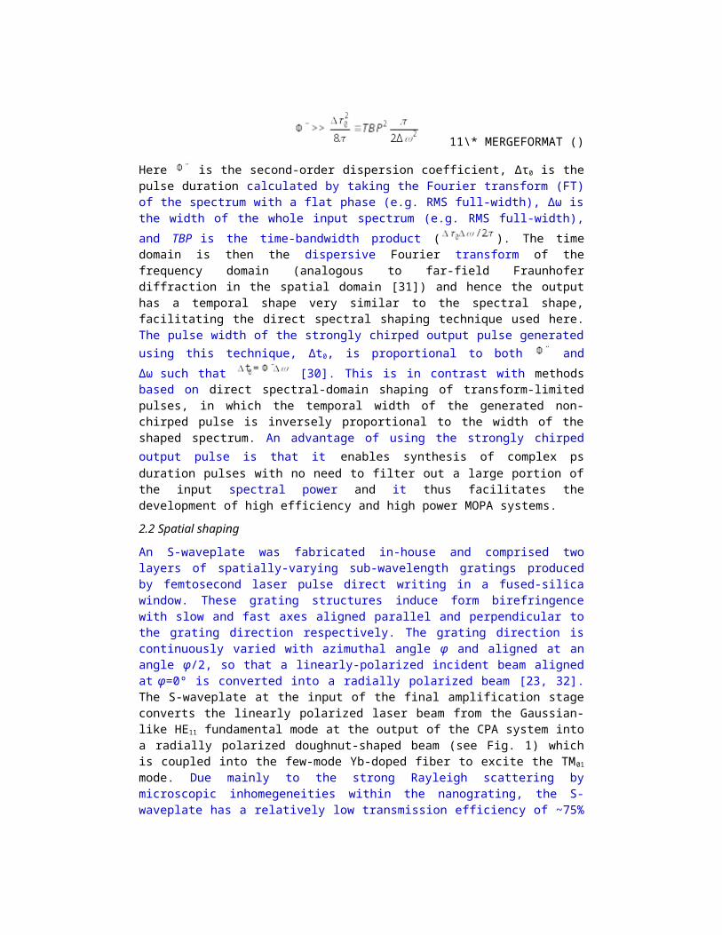
Fig. 2. Flowchart for the control algorithm.
It can be seen from Fig. 3(a) that our control algorithm works very efficiently for the shaping of a square spectrum from 1040.75 nm to 1047.25 nm. After the first iteration, the irregular initial spectrum has already been effectively flattened to better than 2 dB difference between the maximum and the minimum value within the desired bandwidth. Two additional loops further reduce the ripples and create smoother spectra with ~1 dB variations. Due to the strong and predominantly linear chirp, this square spectral profile corresponds to a square pulse in the temporal domain. Our optimized algorithm also works efficiently for the generation of a range of different pulse shapes, including step pulse, double peak energy bridge (DPEB) pulse, and triple peak energy bridge (TPEB) pulse as shown in Fig. 3(b). The corresponding pulse in the time domain of the shaped spectra can be calculated from the spectra by incorporating the chirp in the spectral phase and Fourier-transforming the result according to Eqs. (2) - (4) below, while the autocorrelation (AC) is given by Eq. (5).
22\* MERGEFORMAT ()
33\* MERGEFORMAT ()
44\* MERGEFORMAT ()
55\* MERGEFORMAT ()
Here is the small phase offset remaining due to the mismatch in applied phase between the stretcher and compressor, ∆L is the change in compressor grating separation when one of
the gratings is moved away from the minimum pulse-width position, and and are the second, third, fourth and fifth order dispersion coefficients of the compressor, which are – 9.37× 10⁻² ps2/mm, 1.10 × 10⁻³ ps3/mm, – 2.10 × 10⁻⁵ ps4/mm, and – 5.70 × 10⁻⁷ ps5/mm,

respectively. The values of these parameters were obtained from calculations based on standard formulae [35] and were confirmed by our phase retrieval algorithm based on similar principles to the Multiphoton Intrapulse Interference Phase Scan (MIIPS) method [36]. By far
the dominant term is and hence the pulses are mainly linearly chirped. As it is not possible to directly measure the features created using photo-diodes when they
have durations as short as 5 ps, we confirmed the creation of the expected temporal profile using the second harmonic generation (SHG) AC trace. An example of the results obtained is illustrated in Fig. 3(c). (Note that the y-axis of the spectrum is logarithmic (dB-scale) whereas the time-domain data shows the intensity on a linear scale.) Having calculated the temporal pulse shape from the measured spectrum, the expected SHG AC trace can be evaluated using Eq. (5). The result is compared with the measured SHG AC trace, as shown in Fig. 3(d). The two traces match up well, which confirms that the result is as expected and our shaping technique is accurate. (Minor mismatches between the traces could perhaps be attributed to the effect of the in-band ASE which is present in the fundamental spectrum but does not contribute to the SHG process.)
Fig. 3. Feed-back loop validation results at the output of the CPA system. (a) Progressively improved square spectra for increasing number of iterations. (b) Spectrum shaping results for other pulse shapes. (c) Pulse shape calculated from the measured spectrum. (d) Comparison between the measured autocorrelation trace and autocorrelation trace calculated from the pulse shape in (c).
4. Experimental results and discussionIn this section we first show the temporal shaping of the amplified, 10 W output beam, then the spatial and polarization characterization data. An amplifier gain curve is also provided for the final power-amplifier. We created a selection of temporal pulse profiles: square pulse, step pulse, DPEB and TPEB. The results are shown in Fig. 4(a). The gain in the final amplifier is ~20 dB but the ripples on the shaped spectrum that are often seen to arise with the onset of nonlinear effects in CPA systems are still within 2 dB. Hence the data confirm the
shaping capability of our technique even with a total gain from the amplifiers after the Waveshaper as high as ~53.2 dB. The slope efficiency of the final amplifier is ~77%, as shown in Fig. 4(b). The corresponding pulse trace in the time domain and the expected AC trace of the TPEB pulse were calculated using a FT as explained in Section 3. The traces are shown in Figs. 4(c) and 4(d) and the calculated AC trace agrees well with the measured AC trace.
The peak power of the square pulse, step pulse, the DPEB pulse, and the TPEB pulse in the time domain can also be calculated to be 5.1 kW, 11.8 kW, 11.4 kW and 10.7 kW, respectively. The high peak power values were enabled by mitigating the nonlinearity throughout the system, first by using a CPA architecture for the initial stages and then by maintaining sufficiently long pulses in the final amplifier so nonlinear shaping does not dominate. Note that with the 6.5 nm spectrum used here, the group delay control range of the Waveshaper is -13 ps to +13 ps, which is insufficient for creating the required 50-60 ps pulses so some level of external dispersion is vital.
The twin goals of achieving high power-conversion efficiency and minimizing nonlinearity work together in our approach of performing all temporal shaping and mode-conversion before the power amplifier, as it avoids having components with high loss at the output and thus minimizes the output required from the amplifier needed to achieve 10 W for the envisioned machining task.
Fig. 4. Temporal shaping results after the final ring-mode fiber amplifier (a) Spectral results for different pulse shapes. (b) Power curve for the final amplifier. (c) Pulse shape calculated from the measured spectrum. (d) Comparison between the measured autocorrelation trace and autocorrelation trace calculated from the pulse shape in (c).
Spatially, our attention focused on the widely used radially and azimuthally polarized doughnut-shaped modes (corresponding to TM01 and TE01 modes in fibers). After optimizing the launch of the radially polarized beam into the few-mode YDF, a doughnut-shaped output beam was successfully achieved. This was confirmed by monitoring the beam intensity distribution using a CCD camera. While the doughnut-shaped beam profile was well

maintained, the polarization state changed slightly with variation of the output power, but was otherwise stable when running over several hours in the laboratory environment in the absence of any excess external perturbation to the few-mode YDF. We were able to compensate this change of polarization and re-establish radial polarization through a combination of appropriately oriented quarter- and half-waveplates. Moreover, an azimuthal polarization could be produced by rotation of the half-waveplate by 45°. The measured beam profiles after the final amplifier and waveplates are shown in Figs. 5(a) and 5(b). The inset images in the bottom right of each figure show the mode profiles observed after passing through a linear polarizer oriented in the directions indicated by the white arrows. The images show good purity of the radially and azimuthally polarized modes.
Fig. 5. Doughnut-shaped beam intensity profiles with an output power of 10 W (a) TM01
mode. (b) TE01 mode. The inset: the mode profiles observed after passing through a polarizer oriented in the directions indicated by the white arrows.
Our technique can be used in industrial applications of future systems. The speed of the iterative control algorithm may prevent rapid switching between a range of temporal profiles as might be envisioned for complex machining tasks, but this in no way limits the flexibility as it would be feasible to first test and optimize the temporal profile for each stage of a process using the flexibility of the OAWG and then to restore the different shaping profiles and rapidly recall them on-demand. In regards to the fixed spatial profiles we have demonstrated mode conversion using a fixed S-waveplate. An alternative is to use an SLM for spatial shaping at the input to the final amplifier thus enabling cycling between different temporal and spatial mode combinations as demanded by the processing task.
5. ConclusionsIn conclusion, we have demonstrated arbitrary pulse shaping in the temporal domain, with picosecond duration pulses from an Yb-fiber laser system, combined with effective amplification of a doughnut-shaped beam with radial/azimuthal polarization in the spatial domain. Temporal shaping was achieved using an offset between the stretcher and compressor dispersion in a fiber CPA system to create a linear map from the frequency to the time domain and then simply shaping the spectrum with a rugged, commercially available, fiberized, SLM based, computer-controlled ‘Waveshaper’. The technique we demonstrate is therefore convenient and robust. The use of an iterative closed-loop control algorithm has enabled the demonstration of four complex pulse shapes that are known to improve processing efficiency with shaped pulses operating in the ns regime, but these in no way represent the limit of the capability that this highly flexible architecture enables. The high output power and high efficiency achieved while producing purely radially or azimuthally polarized doughnut-shaped beams show that the potential exists for further power scaling, for example by using a final amplifier with larger mode area. This combination of temporal and modal flexibility with an off-the-shelf fiberized pulse shaper and having high power and high

efficiency promises a step-change in capability for a range of fundamental science and practical laser applications.
FundingThe Engineering and Physical Sciences Research Council (EPSRC) (EP/M014029/1); EPSRC (EP/P012248/1); Air Force Office of Scientific Research (AFOSR) (FA9550-14-1-0382).
AcknowledgementsThe authors would like to thank Dr. Martynas Beresna and Prof. Peter G. Kazansky for providing the S-waveplate.
Data published in this paper are available from the University of Southampton repository at http://doi.org/10.5258/SOTON/D0022.