· web viewceng4480 lab manual 3: audio digitizer and pitch tuner (ver.15.c) ceng4480 embedded...
TRANSCRIPT

1CENG4480 Lab manual 3: audio digitizer and pitch tuner (ver.15.c)
CENG4480 Embedded System Development and Applications
Computer Science and Engineering Department
The Chinese University of Hong Kong
Lab Manual 3: Audio Digitizer and Pitch TunerSeptember, 2016
Introduction
In this lab session you will construct an audio digitizer and learn how to measure the pitch of a music sound and display its frequency onto the screen. Such a device is useful for musicians to tune up their instruments. The processing steps of the signal are as follows:
o Capture the audio signal by a microphone.o Amplify the signal by an operation amplifier (Op-am).o Feed the amplified signal to the Analog-to-digital input (ADC) of the ARM7
microcontroller.o The ARM7 performs Analog to Digital conversion and then uses an
autocorrelation algorithm to find the pitch frequency.o The ARM7 performs Digital to Analog conversion and feeds the signal to
speaker amplifier.o The ARM7 sends the pitch frequency value to a computer via the USB cable
for display.
Autocorrelation [1][2] is a mathematical tool for finding the frequency of a repeating pattern, such as the presence of a periodic signal under noisy environments. It can also be used for identifying the missing fundamental frequency in a signal composed of harmonic frequencies. It is popular in signal processing for analyzing time series signals, such as speech or music audio signals. It can also be treated as the cross-correlation of a signal with itself. For example when the “A” string of a violin oscillates, the sound contains many frequencies, but the strongest frequency is 440 Hz which is called the “pitch” or “fundamental frequency” [3] of this tone.
In signal processing, given a signal f(t), the continuous autocorrelation R f (τ ) is the continuous cross-correlation of f(t) with itself, at lag τ, and is defined as:
R f (τ )=f❑(−τ)∘ f (τ)=∫
−∞
∞
f (t+τ ) f❑(t)dt=¿∫−∞
∞
f (t) f❑( t−τ )dt ¿

2CENG4480 Lab manual 3: audio digitizer and pitch tuner (ver.15.c)
In discrete systems, autocorrelation R at lag j for signal xn is defined as:
R( j)=∑n
(xn¿−m)(xn− j−m)¿
where m is the mean value
When a segment of a signal is correlated with itself, the point at which the next closest maximum correlation R ¿ occurs may be taken to define the fundamental period of the signal.
Then the fundamental frequency f 0can be calculated as:
f 0=1
Lag time= 1j× samplingperiod
=samplingfrequency
j
Objectives
• To learn how to interface an analogue signal to digital systems• To learn how to process audio signals using an embedded system.• To develop an audio digitizer and pitch tuner using an embedded system.
Procedures and what to submit:
Follow the procedures of each experiment. Submit a lab report sheet with your name and student ID, to the tutor after the lab. The lab report sheet should have the measurements or plots of your experiments, and answers of the questions asked in this lab manual. You may prepare the report using a computer document and use a camera to capture the waveforms and insert them in your report.
In your lab report:
Record the displays on the scope for the following procedures. Include the codes of the modified programs required in your report.
Experimental procedures
Procedure 1. Hardware Design

ADC USB cable
3CENG4480 Lab manual 3: audio digitizer and pitch tuner (ver.15.c)
The following diagram shows the hardware system.
Figure 1. Mic amplifier
The audio signal input from the microphone is amplified by a Mic. Amp. Then the amplified signal (0 – 3.3V) is fed to the ADC input of the ARM7 board (AD0.0). The audio signal is then sampled and converted into 8-bit digital data and saved in the internal RAM of ARM7. ARM7 will calculate the autocorrelation value, hence obtain the fundamental frequency.
In the design of the autocorrelation fundamental frequency algorithm, we should consider the following aspects.
(i). Sampling rateThe sampling rate of the ADC used depends on the maximum frequency f maxof input signal. According to Nyquist sampling theorem, the sampling frequency f sampling should be greater or equal to two times f max.
f sampling >=2× f max
In our example, we assume the f max= 10KHz (e.g. the highest note of a piano is C8=4186Hz [4]) , so we choose the sampling frequency f sampling = 20 KHz.
Mic. Amp.ARM7 board ADC
input and DAC output
PC
Speaker Amp.

4CENG4480 Lab manual 3: audio digitizer and pitch tuner (ver.15.c)
Besides of the factor of maximum input frequency, the sampling rate will also affect the accuracy of the system. Since the fundamental frequency will be determined by the number of lag time τ of autocorrelation and actually the lag time τ is the sampling period of the system. The smaller the lag time τ (increasing the sampling frequency) , the smaller is the error and hence increases the accuracy of the system.However, increasing the sampling frequency will increase the record size (number of samples). This means we need more memory space and processing time. Therefore, we have to compromise between these two factors: (i) the accuracy of system and (ii) the time/memory space for processing.
(ii). Minimum record size (Minimum number of samples)The minimum record size chosen depends on the minimum frequency of the input signal. For the same sampling rate, lower the frequency of the input signal will need more number of samples. This is because to successfully calculate the autocorrelation of the signal, we need at least samples of two cycles of this signal.
In our example, we assume the minimum frequency f minof the input signal is 200 Hz. For 20KHz sampling rate the required minimum record size N is:
N=2×f sampling
f min=2×20KHz
200Hz=2×20000
200=200samples
Procedure 2. Software Design
(i). The C Program of our exampleThe flowchart below illustartes the flow of the c program. For details, please read the source program Autocorrelation.c in the Appendix.

5CENG4480 Lab manual 3: audio digitizer and pitch tuner (ver.15.c)
(ii). Lab3.exe program for displaying dataThe Lab3.exe program is used for displaying data received from the ARM7 board. The following picture shows the GUI of the program.
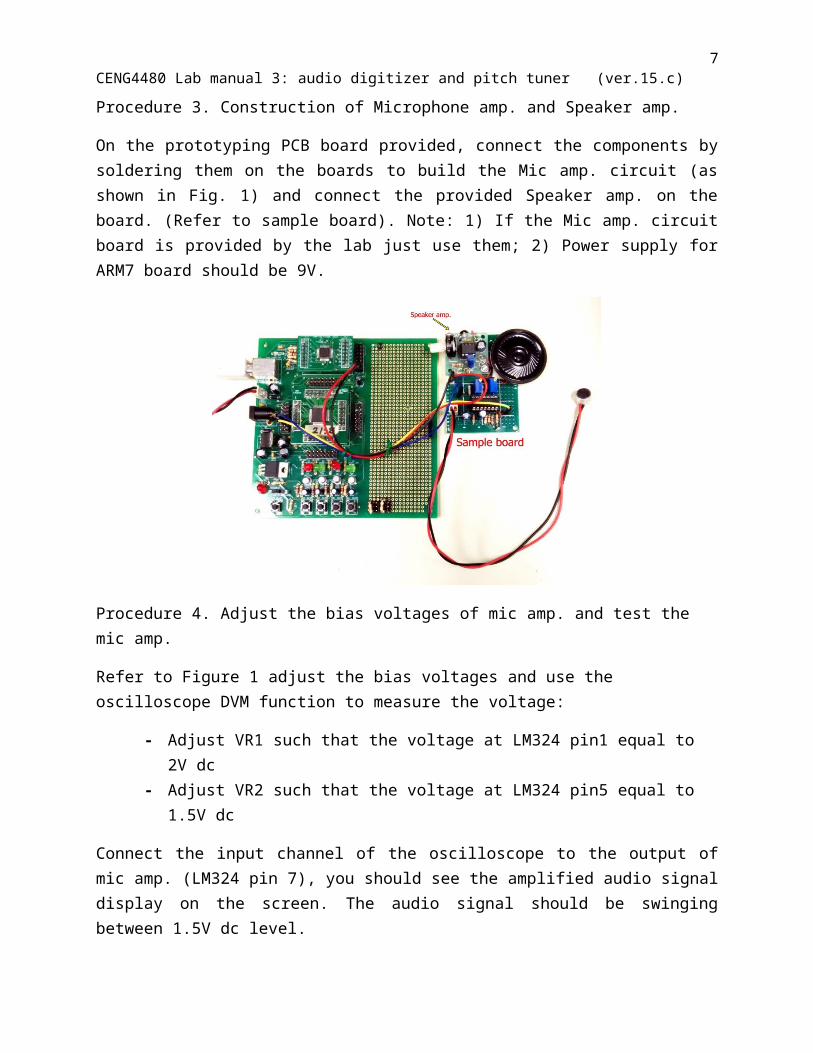
Procedure 3. Construction of Microphone amp. and Speaker amp.

6CENG4480 Lab manual 3: audio digitizer and pitch tuner (ver.15.c)
On the prototyping PCB board provided, connect the components by soldering them on the boards to build the Mic amp. circuit (as shown in Fig. 1) and connect the provided Speaker amp. on the board. (Refer to sample board). Note: 1) If the Mic amp. circuit board is provided by the lab just use them; 2) Power supply for ARM7 board should be 9V.
Procedure 4. Adjust the bias voltages of mic amp. and test the mic amp.
Refer to Figure 1 adjust the bias voltages and use the oscilloscope DVM function to measure the voltage:
- Adjust VR1 such that the voltage at LM324 pin1 equal to 2V dc - Adjust VR2 such that the voltage at LM324 pin5 equal to 1.5V dc
Connect the input channel of the oscilloscope to the output of mic amp. (LM324 pin 7), you should see the amplified audio signal display on the screen. The audio signal should be swinging between 1.5V dc level.
7CENG4480 Lab manual 3: audio digitizer and pitch tuner (ver.15.c)
Sample plot
Procedure 5. Testing the Audio digitizer and Speaker amp.
1. Connect the +5V, GND, MIC_OUT and DAC_OUT to ARM7 board +5V (Pin2 of J10), GND (Pin1 of J10), AD0.0 (Pin11 of H4) and AOUT (AD0.4 Pin9 of H4) respectively (refer to sample board) by using dupont cables. (Refer to picture below)

8CENG4480 Lab manual 3: audio digitizer and pitch tuner (ver.15.c)
2. Download the audio recorder program (2015_audio) to ARM7. Open the Hyper terminal, set the Baud rate to 57600 as shown in Figure 2. Run the program and press r to start recording voice from microphone. Then press p to play the recorded voice on speaker.
Figure 2. HyperTerminal screen

9CENG4480 Lab manual 3: audio digitizer and pitch tuner (ver.15.c)
A clear voice should be heard, if not, please follow the troubleshooting procedure below:
Troubleshooting procedure:
a. Connect the oscilloscope probe to AD0.0 (Pin11 of H4). Then speak something to microphone. You should see corresponding waveforms on the oscilloscope screen. If not, check the bias voltage on Pin1 and Pin5 of LM324. It should be around 2 and 1.5 volts respectively. You can adjust the bias voltage by varying the value of VR1 and VR2.
If your Mic. Amp. still does not operating, possibly there is something wrong in your circuit. Check your circuit hardware connections. If you still have difficulty on troubleshooting your circuit, please don’t hesitate to ask the tutors and technicians.
b. If you have check your Mic. Amp., and it is functions correctly, then connect the oscilloscope probe to AOUT (AD0.4 Pin9 of H4). Record some voice and replay it, there should be corresponding voice waveforms on the oscilloscope screen. If not, check the connections between your board and the ARM7 board.
Otherwise, if AOUT has correct output but your speaker still has no sound output, adjust the volume on the Speaker Amp. board. If there is still no sound output possibly there is something wrong in your Speaker Amp. Check the hardware connection of the Speaker Amp. If you still have difficulty on troubleshooting your circuit, please don’t hesitate to ask the tutors or technicians.
Procedure 6. Observe the effect of sampling rate on the quality of recorded sound wave.
1. Connect Wave Gen output of oscilloscope to the attenuator and connect the attenuator output to the positive of Mic input terminal.
2. Connect the Channel 1 input of oscilloscope to the MIC_OUT.
3. Connect the Channel 2 input of oscilloscope to the DAC_OUT.
Refer to Figure 3 for connection.

10CENG4480 Lab manual 3: audio digitizer and pitch tuner (ver.15.c)
Figure 3. Connection for experiment
4. Configure the waveform generator on the oscilloscope with following settings:Waveform = SineFrequency = 500HzAmplitude = 20mV p-pOffset = 2V
5. Turn on channel 1 and channel 2 displays of oscilloscope. Select channel 2 Coupling to AC. Set appropriate Vertical scales of both channels.
6. Download the audio recorder program (2015_audio) to ARM7. Open the Hyper terminal, set the Baud rate to 57600 as shown in Figure 2. Run the program and press r to start recording voice from microphone. Then press p to display the recorded voice waveform on oscilloscope.
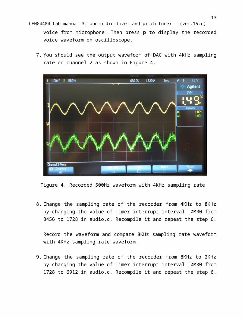
7. You should see the output waveform of DAC with 4KHz sampling rate on channel 2 as shown in Figure 4.

11CENG4480 Lab manual 3: audio digitizer and pitch tuner (ver.15.c)
Figure 4. Recorded 500Hz waveform with 4KHz sampling rate
8. Change the sampling rate of the recorder from 4KHz to 8KHz by changing the value of Timer interrupt interval T0MR0 from 3456 to 1728 in audio.c. Recompile it and repeat the step 6.
Record the waveform and compare 8KHz sampling rate waveform with 4KHz sampling rate waveform.
9. Change the sampling rate of the recorder from 8KHz to 2KHz by changing the value of Timer interrupt interval T0MR0 from 1728 to 6912 in audio.c. Recompile it and repeat the step 6.
Record the waveform and compare 2KHz sampling rate waveform with 8KHz sampling rate waveform.
Procedure 7. Change the pitch in the play back.
(i) Modify the source program (audio.c) such that the play back rate of the recorded sound is slower.
(ii) Modify the source program (audio.c) such that the play back rate of the recorded sound is faster.

12CENG4480 Lab manual 3: audio digitizer and pitch tuner (ver.15.c)
Procedure 8. Pitch tuner by Autocorrelation.
1. Perform Procedure 6 step 1 to step 5.
2. Download the Autocorrelation example (2015_Autocorrelation) program to ARM7 board. Run the Lab3.exe and enter the correct COM number. Then run the example program on the ARM7 by set the programming switch and reset the ARM7 board.
The screen as shown Figure 5 will appear. Then change the frequency of the signal generator. The frequency indicator will also change corresponding to the frequency change.
Figure 5. Pitch tuner by autocorrelation GUI
3. Modify the source program (Autocorrelation.c) to increase the accuracy of the Pitch tuner.
In the final lab report, remember to attach the codes which are written by yourself.
You should also add comments to the codes, e.g.
T0IR = 0x01; // set “1'' to bit [0] to reset the MR0 interrupt.
13CENG4480 Lab manual 3: audio digitizer and pitch tuner (ver.15.c)
END
Appendix/********************************************************************//* *//* Autocorrelation program for CUHK ARM board 2012 *//* (08/2015) *//* *//*******************************************************************//* *//* ARM CPU: Philips LPC2138 *//* Crystal clock: 11.0592 MHz *//* Serial port baudrate: 57600 *//* Programming tool: KEIL uVision3 RealView for ARM *//* *//********************************************************************/#include <lpc21xx.h>extern void init_timer(void);#define TEST_PIN 0x00010000 //set p1.16 as Test pin #define NEWLINE sendchar(0x0a); sendchar(0x0d)#define REC_SIZE 200
//define global variableslong timeval,DA;unsigned char dat[REC_SIZE],finish,play;unsigned long R[50],sum,max,max1,min;unsigned char R1;int P1;
//===============================void Init_Serial_A(void) {
U0LCR = 0x83; //8 bit length ,DLAB=1 //Two lines of code are needed here. You need to define registers so that the baudrate is 57600. ; //Pclk/(16*baudrate)=(11059200 x 5)/(4 x 16 x 57600); ; U0LCR = 0x03; //DLAB=0}
char getchar(void) {volatile char ch = '0';
// Fill in the condition of “while loop” while ( ) // wait until receive a byte ; ch = U0RBR; // receive character
return ch;}
void sendchar(char ch) {// Fill in the condition of “while loop”
while( );
U0THR = ch; // Transmit next character}
int print(char *p) { while(*p!='\0') {
sendchar(*p++); }

14CENG4480 Lab manual 3: audio digitizer and pitch tuner (ver.15.c)
return(0);}
void putint(int count) { sendchar('0' + count/1000);sendchar('0' + (count/100) % 10);sendchar('0' + (count/10) % 10);sendchar('0' + count % 10);
}
unsigned char read_sensor(int channel){
int temp;
ADCR=0x1<<channel; //Set channel SEL fieldADCR|=0x1200200; //Start conversion now; ADC is operational;
//11 clocks/ 10 bits; Software conversion mode;//CLKDIV = 2; ADclk = Pclk/(CLKDIV+1)//ADclk = (11059200 x 5)/(4 x 3) = 4.608MHz
while(((temp=ADDR)&0x80000000)==0); //check DONE flag//temp>>=6; //ADDR p6-p15 = RESULT//temp&=0x3ff;//10 bits result ; //ADDR p6-p15 = RESULT, write your code in this line. temp&=0xff;//8 bits result
//return (temp*33); //return 0-3V value precision is 256 return (temp); //return 0-3V value precision is 256
}
int main(void){
int i,j;
PINSEL0 = 0x00000005; // set p0.0 to TXD0, p0.1 to RXD0 and the rest to GPIO PINSEL1 = 0x00400000; // set p0.27 to ad0.0 and the rest to GPIO PINSEL1 |= 0x00080000; // set p0.25 to AOUT (DAC)
Init_Serial_A(); // Init COM port init_timer(); // Init TIMER 0
NEWLINE; print("======================================================================="); NEWLINE; print("* *"); NEWLINE; print("* CUHK Computer Science and Engineering Department *"); NEWLINE; print("* LPC2138 ARM Board (2012) Autocorrelation (08/15) *"); NEWLINE; print("* *"); NEWLINE; print("======================================================================="); NEWLINE; NEWLINE;
IO1DIR|=TEST_PIN; // p1.16 as Outputs
while(1) {
// start record 200 samplesfinish = 0;timeval = 0;while(finish==0) {} // wait until recording finish

15CENG4480 Lab manual 3: audio digitizer and pitch tuner (ver.15.c)
// find the min/mean valuemin = 0xffff;for(i=0;i<REC_SIZE;i++) {
if(dat[i]<min) min = dat[i];}
// subtract min/mean value from all datafor(i=0;i<REC_SIZE;i++) dat[i] -= min;
// calculate the autocorrelationfor (j=1;j<(REC_SIZE/2)+1;j++) {
}
// find the max. value (used for prevent false max1.) max = 0;for(i=0;i<REC_SIZE/2;i++) {
if(R[i]>max) max = R[i];}
// find the first max. valueR1 = 0;max1 = 0xffffffff;for(i=5;i<REC_SIZE/2;i++) { if((R1==0)&&(R[i]<max1)) max1 = R[i]; // the first negative slope of the curve else if((R1==0)&&(R[i]>max1)) R1 = 1; // end of the first negative slope of the curve
if((R1==1)&&(R[i]>max1)) max1 = R[i]; // the first positive slope of the curve else if((R1==1)&&(R[i]<max1)&&(max-max1)<max/10) { // the max1 point is reach andprevent false max1.
P1 = i; // record the max1 pointR1 = 2;
}}// convert to frequency and send via rs232print("F"); // start flag of dataif(P1>=10) putint(20000/P1); // Frequency = 20KHz/P1, where P1 is the point of first max.else putint(9999); // invalid dataNEWLINE;
}}
void __irq IRQ_Exception(){
// Audio recording if((finish==0)&&(timeval<REC_SIZE)) {
dat[timeval] = read_sensor(0);timeval++;
}if((finish==0)&&(timeval>=REC_SIZE)) finish = 1;
// Audio playing//if((play==0)&&(timeval<REC_SIZE)) {// DA = dat[timeval];// DA <<=8;// DA &= 0xff00;// DACR = DA;// timeval++;//}

16CENG4480 Lab manual 3: audio digitizer and pitch tuner (ver.15.c)
//if((play==0)&&(timeval>=REC_SIZE)) play = 1;
T0IR = 1; // Clear interrupt flag VICVectAddr = 0; // Acknowledge Interrupt}
/* Setup the Timer Counter 0 Interrupt */void init_timer (void) {//One line of code is needed here, which set prescaler to 0 // set prescaler to 0 T0MR0 =691; // set interrupt (sampling rate) to 20KHz
// Pclk/4KHz = (11059200 x 5)/(4 x 20000)//One line of code is needed here, which enables Interrupt and Reset on MR0 // Interrupt and Reset are enabled on MR0 T0TCR = 1; // Timer0 Enable VICVectAddr0 = (unsigned long)IRQ_Exception; // set interrupt vector in 0 VICVectCntl0 = 0x20 | 4; // use it for Timer 0 Interrupt VICIntEnable = 0x00000010; // Enable Timer0 Interrupt}
Reference:
[1]http://en.wikipedia.org/wiki/Autocorrelation
[2] http://cnx.org/content/m13391/latest/
[3] https://en.wikipedia.org/wiki/Pitch_(music)