eprints.whiterose.ac.ukeprints.whiterose.ac.uk/126184/1/revised_manuscript_2017... · web...
TRANSCRIPT

Magneto-optical detection of spin accumulation under the influence of mechanical rotation
Atsufumi Hirohata,1,* Yuji Baba,2 Benedict A. Murphy,3 Benny Ng,4 Yunqi Yao,4 Kazuki Nagao 5
and Jun-young Kim 3
1 Department of Electronic Engineering, University of York, Heslington, York YO10 5DD, U.K.2 Department of Materials Science and Technology, Nagaoka University of Technology, Nagaoka 940-
2188, Japan3 Department of Physics, University of York, York YO10 5DD, U.K.4 Department of Electronic Engineering, City University of Hong Kong, Kowloon Tong, Hong Kong5 Department of Electrical Electronics and Information Engineering, Nagaoka University of
Technology, Nagaoka 940-2188, Japan* e-mail: [email protected]
The generation of spin-polarised carriers in a non-magnetic material holds the key to realise highly efficient spintronic devices. Recently, it has been shown that the large spin-orbit coupling can generate spin-polarised currents in noble metals such as tungsten and platinum. Especially, if small samples of such metals are rotated on a plane disc in the presence of a perpendicular magnetic field, the orbital angular momentum is altered leading to a segregation of spin up and spin down electrons, i.e., a spin current in the samples. This is manifested via an induced magnetic moment on the metal. In this letter, magneto-optical Kerr effect (MOKE) is used to detect induced magnetic moments which allows remote measurements on metal samples rotating at 100 ~ 210 Hz. Our results confirm the mechanical generation of spin-polarised currents via optical detection of spin accumulation.
Introduction
Electron spin angular momentum is conserved in interactions with magnetic moments,
circularly-polarised photons and electrons.1,2 A steady flow of spin angular momentum in absence
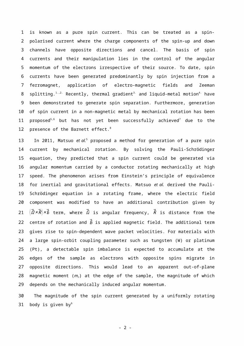
of any net charge flow is known as a pure spin current. This can be treated as a spin-polarised
current where the charge components of the spin-up and down channels have opposite
directions and cancel. The basis of spin currents and their manipulation lies in the control of the
angular momentum of the electrons irrespective of their source. To date, spin currents have been
generated predominantly by spin injection from a ferromagnet, application of electro-magnetic
fields and Zeeman splitting.1,2 Recently, thermal gradient3 and liquid-metal motion4 have been
demonstrated to generate spin separation. Furthermore, generation of spin current in a non-
magnetic metal by mechanical rotation has been proposed5,6 but has not yet been successfully
achieved7 due to the presence of the Barnett effect.8
- 1 -
1
2
3
4
5
67
8
9
1011
12
13
14
15
16
17
18
19
20
21
22
23
24
25
26
27
28
29
30
31
32
33
34
35
In 2011, Matsuo et al.5 proposed a method for generation of a pure spin current by mechanical
rotation. By solving the Pauli-Schrödinger equation, they predicted that a spin current could be
generated via angular momentum carried by a conductor rotating mechanically at high speed.
The phenomenon arises from Einstein’s principle of equivalence for inertial and gravitational
effects. Matsuo et al. derived the Pauli-Schrödinger equation in a rotating frame, where the
electric field component was modified to have an additional contribution given by ( Ω⃗× R⃗ )×B⃗
term, where Ω⃗ is angular frequency, R⃗ is distance from the centre of rotation and B⃗ is applied
magnetic field. The additional term gives rise to spin-dependent wave packet velocities. For
materials with a large spin-orbit coupling parameter such as tungsten (W) or platinum (Pt), a
detectable spin imbalance is expected to accumulate at the edges of the sample as electrons
with opposite spins migrate in opposite directions. This would lead to an apparent out-of-plane
magnetic moment (mz) at the edge of the sample, the magnitude of which depends on the
mechanically induced angular momentum.
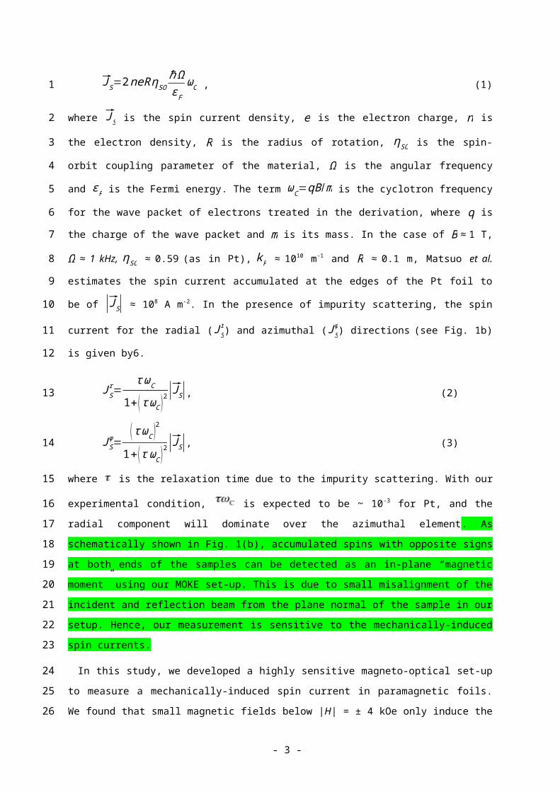
The magnitude of the spin current generated by a uniformly rotating body is given by6
J⃗S=2neRηSOℏΩεFωC , (1)
where J⃗S is the spin current density, e is the electron charge, n is the electron density, R is the
radius of rotation, ηSO is the spin-orbit coupling parameter of the material, Ω is the angular
frequency and εF is the Fermi energy. The term ωC=qB /m is the cyclotron frequency for the
wave packet of electrons treated in the derivation, where q is the charge of the wave packet and
m is its mass. In the case of B ≈ 1 T, Ω ≈ 1 kHz, ηSO ≈ 0.59 (as in Pt), k F ≈ 1010 m-1 and R ≈ 0.1
m, Matsuo et al. estimates the spin current accumulated at the edges of the Pt foil to be of |⃗J S| ≈
108 A m-2. In the presence of impurity scattering, the spin current for the radial (JSr ) and azimuthal
(JSϕ) directions (see Fig. 1b) is given by6
JSr=
τ ωC1+ (τ ωC )2 |⃗J S|, (2)
JSϕ=
( τ ωC )2
1+ (τ ωC )2 |⃗J S|, (3)
where is the relaxation time due to the impurity scattering. With our experimental condition,
is expected to be ~ 10-3 for Pt, and the radial component will dominate over the azimuthal
element. As schematically shown in Fig. 1(b), accumulated spins with opposite signs at both
ends of the samples can be detected as an in-plane “magnetic moment” using our MOKE set-up.
This is due to small misalignment of the incident and reflection beam from the plane normal of
the sample in our setup. Hence, our measurement is sensitive to the mechanically-induced spin
- 2 -
1
2
3
4
5
6
7
8
9
10
11
12
13
14
15
16
17
18
19
20
21
22
23
24
25
26
27
28
29
30
31
currents.
In this study, we developed a highly sensitive magneto-optical set-up to measure a
mechanically-induced spin current in paramagnetic foils. We found that small magnetic fields
below |H| = ± 4 kOe only induce the Barnett effect for the foil attached on a rotational plate with
the radius of 0.10 m. On the other hand, the fields above ± 4 kOe were found to generate the
spin current discussed above. Such a spin current proves that the spin-polarised carrier can be
generated by mechanical rotation, which is analogous to the spin Hall effect.
Results
Paramagnetic W and Pt foils (99.95% purity) were chosen due to their large values of
arising from high density of states at the Fermi level. Here, 100-µm-thick Pt and body-centred
cubic W samples have opposite spin-Hall angles, 0.056 for Pt9 and -0.35 (-0.5) for W10 (W-Ox11).
The foils of 2 mm diameter were polished to a < 0.3 µm surface roughness. The samples were
mounted on a NdFeB permanent magnet painted in matte black with surface stray fields between
1 kOe and 5 kOe. For each measurement the NdFeB magnet was fixed at a radial distance of
0.10 m on a balanced carbon fibre plate painted in matte black and rotated at frequencies of up
to f = 210 Hz (12,600 rpm) thereby varying the angular momentum. The experimental
arrangement is shown in Fig. 1a. The spin current in the foil (see Fig. 1b) was observed via the
resulting induced moment using a magneto-optical Kerr effect (MOKE) magnetometer. It should
be noted that the MOKE signals only represent the induced moments near the surface of the
paramagnetic foils as their thicknesses, ~ 80 m, well exceed the penetration depth of the He-Ne
laser beam, < 100 nm as detailed in sample preparation in Methods. A direct measurement of the
change in moment was made by taking the difference between two signals registered by two
photodetectors using a 3.5 GHz oscilloscope (Tektronix DPO7354C) (see Methods for details).
- 3 -
1
2
3
4
5
6
7
8
9
10
11
12
13
14
15
16
17
18
19
20
21
22
23
24

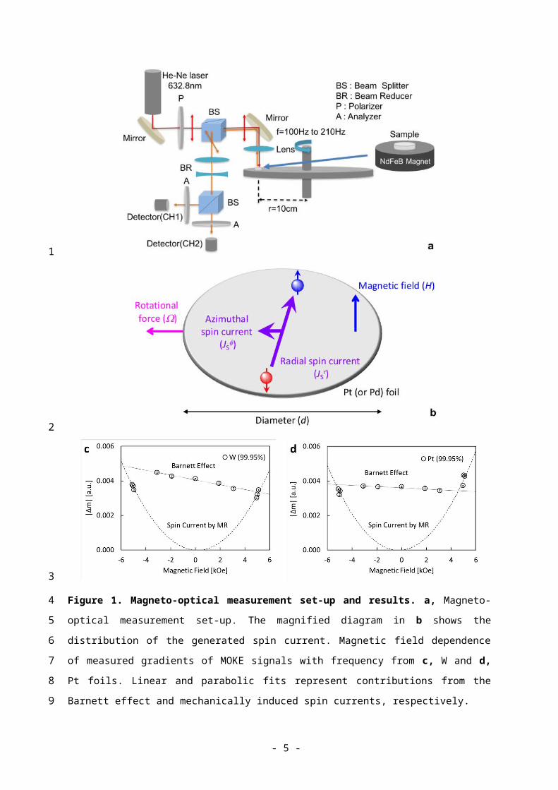
Figure 1. Magneto-optical measurement set-up and results. a, Magneto-optical measurement
set-up. The magnified diagram in b shows the distribution of the generated spin current.
Magnetic field dependence of measured gradients of MOKE signals with frequency from c, W
and d, Pt foils. Linear and parabolic fits represent contributions from the Barnett effect and
mechanically induced spin currents, respectively.
Figures 1c and 1d shows the variation of the gradient of the MOKE signals, |m|, due to the
induced moments in W and Pt foils, respectively. The MOKE signals were measured as the
difference in two photodetector signals with the rotational frequency between 150 and 210 Hz at
a fixed radius of 0.10 m. Here, m is expected to be proportional to the spin current induced in
the W and Pt foils. The details of the signal acquisition are described in Methods. The zero-field
data were taken from W and Pt foils attached to a brass tube with the same dimensions with the
permanent magnets used in this study. The output gradient is directly proportional to the sum of
the field from the magnet and the induced magnetic moment due to the Barnett effect below |H| =
± 4 kOe. Here, the magnetic flux density from the Barnett effect (BB) is induced perpendicular to
the foil by the rotation of electrons in the sample:8
BB=2meΩ. (4)
By considering the average angular frequency used in our measurements (150 Hz), BB is
- 4 -
1
2
3
4
5
6
7
8
9
10
11
12
13
14
15
16
17
18
19
estimated to be 1.71 × 10⁻⁹ Wb m-2. This gives a magnetic moment of 5.40 × 10⁻¹⁵ Wb within the
2-mm-diameter circular foil, indicating that our MOKE set-up is sensitive to such a small
magnetic moment. Using the least squares method, these results can be fitted to parabolic and
linear functions as detailed in Discussion.
Discussion
The gradient of our MOKE signal with the rotation frequency is expected to contain information
from three different phenomena: reduction of the laser beam exposure time due to faster rotation,
moment induced from the Barnett effect, and spin accumulation from the mechanically-generated
spin current. First two phenomena, namely from the faster rotation and the Barnett effect, are
expected to contribute linearly with the magnetic field strengths. On the other hands, the
mechanically-generated spin currents have quadratic dependence on the field strength. As seen
in Figs. 1(c) and (d), we compare the gradients of normalised MOKE signals from samples on
different magnet field strengths in order to differentiate the effects of the mechanically-generated
spin current from the first two contributions.
For |H| < 4 kOe, the MOKE gradient signal is linearly proportional to the field, as expected from
the moments induced by the Barnett effect. The linear fitting of the data points within this field
range results in the linear coefficients of (1.34 ± 0.19) × 10-4 and (4.2 ± 1.2) × 10-5 for W and Pt,
respectively, giving the ratio of 3.2 ± 1.0. Furthermore, in order to quantify the moments induced
by the Barnett effect, magnetic susceptibility values of our W and Pt foils were measured by VSM
to be 3.0 × 10⁻⁶ and 2.6 × 10⁻⁶ (emu cm-3) Oe-1, respectively (see Methods for details), leading to
the ratio of 1.2. We expect the discrepancy between the two ratios to be due to the errors in the
estimation of the small foil volumes.
When |H| > 4 kOe, the MOKE gradient signals start to show higher order field dependencies.
This suggests the emergence of the mechanical spin current and the resulting magnetic
moment.5 The larger second-order coefficient of the W data, as compared to the Pt, agrees with
the prediction as discussed in Eq. (2). The second-order field dependence of the induced
moment is interpreted as the first experimental observation of mechanically induced spin
currents. For our experimental condition for Pt, a (radial) spin current density of ≈ 3 × 10³ A m-2
should be induced according to Eq. (2). Matsuo et al.6, estimated the spin accumulation due to
the mechanically-generated spin current to be around 0.05 neV for a Pt film with a length of 100
nm. Assuming that the magnitude of the spin accumulation is linearly proportional to the length of
the film, the spin accumulation at the edges of our 2 mm diameter Pt film is estimated to be
around 1 µeV. It should be noted that the mechanically-generated spin current is an order of
magnitude smaller than the conventional spin current generated by spin pumping,12 but the
magnitude can be increased by using a larger rotational diameter and a higher angular
- 5 -
1
2
3
4
5
6
7
8
9
10
11
12
13
14
15
16
17
18
19
20
21
22
23
24
25
26
27
28
29
30
31
32
33
34
35

frequency.
Methods
Sample preparation. W and Pt foils with thickness of 100 µm (99.95% purity) were glued onto
NdFeB magnets and polished using diamond lapping pads (30, 15, 3 and 1 µm) to a 1 µm finish.
The foils were then polished using water solution with aluminium oxide particles of 0.3 µm
diameter. During polishing the samples were kept level on a tripod polishing mount. The
thickness of the polished foils were measured to be (81.5 1.6) µm and (79.5 0.5) µm for W
and Pt, respectively.
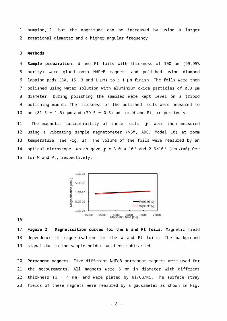
The magnetic susceptibility of these foils, χ , were then measured using a vibrating sample
magnetometer (VSM, ADE, Model 10) at room temperature (see Fig. 2). The volume of the foils
were measured by an optical microscope, which gave χ = 3.0 × 10⁻⁶ and 2.6×10⁻⁶ (emu/cm3) Oe-
1 for W and Pt, respectively.
Figure 2 | Magnetisation curves for the W and Pt foils. Magnetic field dependence of
magnetisation for the W and Pt foils. The background signal due to the sample holder has been
subtracted.
Permanent magnets. Five different NdFeB permanent magnets were used for the
measurements. All magnets were 5 mm in diameter with different thickness (1 ~ 4 mm) and were
plated by Ni/Cu/Ni. The surface stray fields of these magnets were measured by a gaussmeter
as shown in Fig. 3. A 5-mm-diameter brass piece was also used as a zero-field reference.
- 6 -
1
2
3
4
5
6
7
8
9
10
11
12
13
14
15
16
17
18
19
20

Figure 3 | Measured magnetic fields generated by permanent magnets. Magnetic fields
measured by a gaussmeter at room temperature.
MOKE set-up. He-Ne laser (Melles Griot, 05-STP-903, wavelength: 632.8 nm and power: 1.0
mW) was used to detect Kerr rotation of the linear polarisation of the light reflected from the
surface of the paramagnetic foils. The rotation was caused due to the magnetic moment induced
by a spin-polarised current accumulated at the edge of the foils. The beam was introduced in the
plane normal to the surface of the sample centre with the typical penetration depth of < 100 nm.
As shown in Fig. 4, the reflected beam was split into two linearly polarised beams, and measured
using two photodetectors (Thorlabs, DET36A Si Detector), CH1 and CH2, in the cross-Nicol
configuration.13,14 For demonstration, we assume that the incident beam is linearly polarised
along the x direction:
E⃗1=E0(10). (5)
Upon reflection off the sample, the linear polarisation of the beam is rotated by the Kerr angle
θK:
E⃗2=E0(cosθK −sin θK
sin θK cosθK)(10)=E0(cosθK
sin θK ). (6)
The reflected beam then passes through a non-polarising beam splitter, where each-split beam
passes through the linear polarisers set orthogonally at 45° and 135° from the x-axis,
respectively, then reaches the two photodetectors CH1 and CH2:
E⃗2 ,CH 1=E0cos ( π4−θK )= E0
√2( cosθK+sin θK ), (7)
E⃗2 ,CH 2=E0sin( π4 −θK)= E0
√2(cosθK−sin θK ). (8)
The difference between the two photodetector voltages can be computed as follows:
- 7 -
1
2
3
4
5
6
7
8
9
10
11
12
13
14
15
16
17
18
19
20
21
22
V 1−V 2=|⃗E2 ,CH 1|2-|⃗E2 , CH 2|
2=E0
2
2 [ ( cosθK+sin θK )2−( cosθK−sin θK )2 ]¿2 E0
2 cosθK sinθK=E02 sin 2θK . (9)
For small Kerr rotation angles, sin 2θK can be treated as 2θK:
V1-V2 = 2 E02 θK for small θK. (10)
Therefore, θK is proportional to the difference in the two photodetector voltages V1-V2.
Figure 4 | MOKE setup. Schematic diagram of the MOKE measurement system with the
corresponding polarisation of incident and reflection beams.
The cross-Nicol configuration was determined by calibrating the detector signals for every
sample. Here, the polariser angle for the incident beam was fixed to be 0º, while the two analyser
angles were selected to maximise the changes in the signals, i.e. at the point where the gradient
of the sine MOKE signals takes the maximum, as shown in Fig. 5. For the calibration, the foil was
rotated at a frequency of 20 Hz and the reflection was measured by the two detectors
simultaneously with changing their polariser angles from 0 to 360 at steps of 10. Representative
results are shown in Fig. 5 for the Pt foil with the N42_4mm magnet (with the surface stray field
of ~ 5.1 kOe). The detector polariser was then adjusted to maximise the gradient of the detector
signals. A list of polariser angles used is shown in Tables 1 and 2.
- 8 -
1
2
3
4
5
6
7
8
9
10
11
12
13
14
15
16
17

Figure 5 | Calibration results. Polariser angle dependence of the detector signals. The data
was taken at 10 steps and was fitted with a cos2 function.
Table 1 | List of detecting polariser angles for the W foils.
Magnet Analyser angleGrade Thickness [mm] Direction CH1 [] CH2 []N42 4 - 20.6 69.5N42 3 - 34.9 39.1N52 3 - 25.4 50.3N35 2 - 15.9 61.1N42 1 - 18.3 71.1
Brass 2mm 32.9 33.4N42 1 + 38.9 31.1N35 2 + 51.1 25.8N52 3 + 20.8 68.1N42 3 + 21.3 67.5N42 4 + 27.2 50.3
Table 2 | List of detecting polariser angles for the Pt foils.
Magnet Analyser angleGrade Thickness [mm] Direction CH1 [] CH2 []N42 4 - 21.5 67.6N42 3 - 26.5 53.7N52 3 - 20.2 71.0N35 2 - 20.4 69.2N42 1 - 20.8 62.1
Brass 2mm 20.9 62.4N42 1 + 19.8 65.8N35 2 + 23.7 56.6N52 3 + 21.1 63.7N42 3 + 21.3 69.5N42 4 + 21.5 63.9
Signal Acquisition. Our MOKE signals were acquired at the rotation frequency between 100 Hz
and 200 Hz. The frequency range was chosen so that the rotation of the disc was free from the
resonance of neighbouring equipment and the sample plane became consistently perpendicular
to the incident laser beam. As the sample only stayed under the laser beam for a short time
(approximately 32 µs at 100 Hz) for each rotation, our signal was of a pulsed nature, as
- 9 -
1
2
3
4
5
6
7
8
9
10
11

displayed in Fig. 6(a). Relatively long (~ 1 ms) pulse-widths of our signal, as compared to the
estimated beam exposure time, were attributed to be due to long “cool-down” times of the CCDs
in our photodetectors. The 3.5 GHz Tektronix oscilloscope was used to record our pulsed signal
from the photodetectors, where a built-in program was used to extract the effective magnitude of
each pulse peak as compared to the background level.
The measured peak magnitude value was then recorded against the rotation frequency, as
shown in Fig. 6(b). The almost linear decrease of the peak height with the rotation frequency was
due to the reduction in the time the sample stays under the laser beam as expected, leading to
the drop in the measured intensity. In order to compensate for the slight changes in the optics
alignment for each measurement, the obtained peak value was normalised to its value at 100 Hz,
as seen in Figs. 6(c) and (d), so that the relative decrease in the signal with the frequency for
different measurements could be compared quantitatively.
Without this normalisation step, the peak height values from different measurements could not
be compared directly due to the changes in the observed intensity from the non-identical optics
alignment. We had tried to position the sample manually under the laser beam and measure the
MOKE signal directly without rotation. However, the exact position of the beam relative to the
sample was found to change each time we change the magnet or sample, which led to large and
unsystematic changes in the measured MOKE signal. This was predominantly because the
sample attached on a permanent magnet needs to be fixed on the rotating plate using glue,
causing minor misalignment in the sample plane with respect to the rotating plate plane.
Consequently, rotation of the sample was necessary, not only to investigate the rotational effects,
but also for the normalisation of the measured signals. Gradients of the normalised signals were
compared to quantify effects of spin currents from the rotation motion, as discussed in
Introduction.
- 10 -
1
2
3
4
5
6
7
8
9
10
11
12
13
14
15
16
17
18
19
20
21
22
23
24
25
26

a
-0.01 -0.005 0 0.005 0.010
1
2
3
4ch1ch2
time[sec]
V [
V]
b
140 150 160 170 180 190 200 2100.02
0.025
0.03
0.035
0.04
0.045
0.05 1
2
3
4
5
6
7
8
9
10Frequency [Hz]
MO
KE
sign
al [V
]
c
Norm
alised
MO
KE
signal
[a.u.]
- 11 -
1
2
3

d
Figure 6 | Signal acquisition. a, Representative MOKE signals measured at the rotation
frequency of 30 Hz. b, Peak MOKE signals at the frequency between 100 and 210 Hz for the Pt
foil with the magnet N42_4mm (~ 5.1kOe). c, Corresponding MOKE signals normalised to the
signals measured at 100 Hz. d, Averaged MOKE signals over 10 measurements shown in c.
In summary, we have demonstrated experimentally non-linear dependence of the spin
accumulation with field at the edge of paramagnetic foils on a rotating plate, as theoretically
predicted.5 This finding establishes an alternative method to generate a pure spin current
induced by the conservation of angular momentum of electron spin under mechanical rotation.
Our optical detection opens a new research field of spin mechatronics, which may offer a
template to investigate further relationships between mechanical motion and spin angular
momentum.
After submitting this manuscript, Kobayashi et al. [15] reported a noble method of detecting
spin currents generated by using Rayleigh-type surface acoustic wave (SAW) in Ni81Fe19 / Cu
bilayer system. By measuring microwave absorption at SAW excitation frequency at 1.5 GHz, a
large spin-rotation coupling effect was observed.
References
1. Maekawa, S., Vanenzuela, S. O., Saitoh, E., & Kimura, T. (Eds.) Spin Current (Oxford
University Press, Oxford, 2012).
2. Hirohata, A. & Takanashi, K., Future perspectives for spintronic devices (topical review),
Journal of Physics D: Applied Physics 47, 193001 (2014).
3. Uchida, K. et al., Observation of the spin Seebeck effect, Nature 455, 778 (2008).
4. Takahashi, R. et al., Spin hydrodynamic generation, Nature Physics 12, 52 (2016).
5. Matsuo, M., Ieda, J., Saitoh, E. & Maekawa, S. Effect of mechanical rotation on spin
currents. Physical Review Letters 106, 076601 (2011).
Norm
alised MO
KE
signal [a.u.]
- 12 -
1
2
3
4
5
6
7
8
9
10
11
12
13
14
15
16
17
18
19
20
21
22
23
24
25

6. Matsuo, M., Ieda, J., Saitoh, E. & Maekawa, S. Spin current generation due to mechanical
rotation in the presence of impurity scattering. Applied Physics Letters 98, 242501 (2011).
7. Chudo, H. et al., Observation of Barnett fields in solids by nuclear magnetic resonance,
Applied Physics Express 7, 063004 (2014).
8. Barnett, S. J., Magnetization by Rotation. Physical Review 6, 239 (1915).
9. Rojas-Sánchez, J.-C. et al., Spin Pumping and Inverse Spin Hall Effect in Platinum: The
Essential Role of Spin-Memory Loss at Metallic Interfaces. Physical Review Letters 112,
106602 (2014).
10. Pai, C. F. et al., Spin transfer torque devices utilizing the giant spin Hall effect of tungsten.
Applied Physics Letters 101, 122404 (2012).
11. Demasius, K.-U. et al., Enhanced spin–orbit torques by oxygen incorporation in tungsten
films. Nature Communications 7, 10644 (2016).
12. Ando, K. et al., Angular dependence of inverse spin–Hall effect induced by spin pumping
investigated in a Ni81Fe19/Pt thin film. Physical Review B 78, 014413 (2008).
13. Osterloh, I. et al., A theoretical study of the magneto-optical Kerr effect in FeX (X=Co, Ni, Pd,
Pt). J. Phys.: Condens. Matter 6, 285 (1994).
14. Valev, V. K., Wouters, J. & Verbiest, T., Differential detection for measurements of Faraday
rotation by means of ac magnetic fields. Eur. J. Phys. 29, 1099 (2008).
15. Kobayashi, D. et al., Spin current generation using a surface acoustic wave generated via
spin-rotation coupling. Physical Review Letters 119, 077202 (2017).
Acknowledgements
The authors wish to thank A. J. Vick, D. Coulthard and B. Wilkinson for their support to develop
the rotational system. The authors also acknowledge useful discussions with Profs. S. Maekawa,
K. O’Grady as well as Drs. M. Matsuo and J. Ieda in preparation of the manuscript. Y.B. and K.N.
thanks the Nagaoka University of Technology for their internship programme. B.A.M.
acknowledges the financial support of JEOL U.K. B.N. and Y.Y. are grateful for the City University
of Hong Kong for their summer internship programme. This work was partially supported by JST
Precursory Research Embryonic Science and Technology (PRESTO) program and EPSRC
Grant (EP/M02458X/1).
Author contributions
A.H. conceived the study and co-wrote the paper with B.A.M. Y.B., B.A.M., K.N. and J.-Y.K.
prepared the samples and carried out the magneto-optical measurements. The measurement
programme was developed by B.N. and Y.Y. They interpreted the data with A.H. All authors
discussed the results and commented on the manuscript.
- 13 -
1
2
3
4
5
6
7
8
9
10
11
12
13
14
15
16
17
18
19
20
21
22
23
24
25
26
27
28
29
30
31
32
33
34

Additional information
Supplementary information regarding the data analysis is available in the online version of the
paper. Reprints and permission information is available online at www.nature.com/reprints.
Correspondence and requests for materials should be addressed to A.H.
Competing financial interests
The authors declare no competing financial interests.
- 14 -
1
2
3
4
5
6