view our inventory instruction manual (b) description of this product consists of the three-volumed...
TRANSCRIPT
MT-46E-101-A
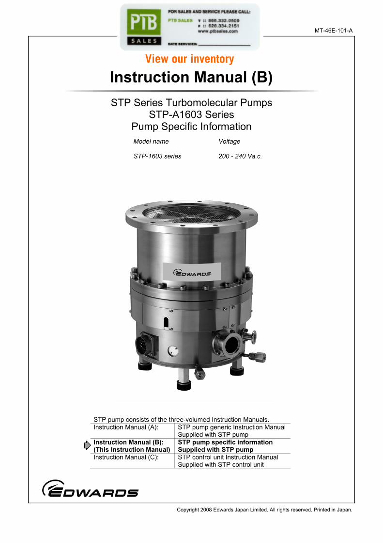
Model name Voltage
STP-1603 series 200 - 240 Va.c.
STP Series Turbomolecular Pumps STP-A1603 Series
Pump Specific Information
Instruction Manual (B)
STP pump consists of the three-volumed Instruction Manuals. Instruction Manual (A): STP pump generic Instruction Manual
Supplied with STP pump Instruction Manual (B): (This Instruction Manual)
STP pump specific information Supplied with STP pump
Instruction Manual (C): STP control unit Instruction Manual Supplied with STP control unit
Copyright 2008 Edwards Japan Limited. All rights reserved. Printed in Japan.
View our inventory

The description of this product consists of the three-volumed Instruction Manuals. Read through each Instruction Manual before operation. The separate volume contents of each description are as follows:
Instruction Manual (A)
STP pump generic Instruction Manual:
• Introduction
• Installation of the STP pump
• Installation of the STP control unit
• Operation
• Safety functions
• Maintenance and inspection
• Storage and disposal
• Service, Spares and accessories
Instruction Manual (B)
STP Pump specific information:
• Technical data
• How to Secure the STP pump
• Temperature Management System (TMS)
Instruction Manual (C)
STP control unit Instruction Manual:
• Introduction
• Technical data
• Installation
• Operation
• Serial communication protocol
• STP-Link (except for SCU-750)
• Maintenance
• Storage, transportation and disposal
• Service, spares, and accessories
Keep the manuals in an easily accessible location.

STP-A1603 Series Turbomolecular Pump
July 08 i Issue 1-a
PAGEi CONTENTS
Section Title Page
1 TECHNICAL DATA 1
1.1 Applicable pump specifications 1 1.1.1 STP pump specifications 2 1.1.2 Condition for the water-cooling unit 3 1.2 External appearance of the STP pump 3 1.3 Label affixing positions 6 1.4 Accessories 7
2 HOW TO SECURE THE STP PUMP 9
2.1 When securing the inlet port with bolts 10 2.2 When securing the inlet port flange with claw clamps 11 2.3 When installing the damper in the inlet port flange 12
3 TEMPERATURE MANAGEMENT SYSTEM (TMS) 13
3.1 Configuration of the STP pump with the TMS 13 3.2 TMS connection cable 14 3.3 TMS heater 14 3.4 TMS valve 14 3.5 TMS sensor cable 14 3.6 Installation of the TMS unit 15 3.6.1 Connecting the TMS connection cable to the STP control unit 15 3.6.2 Connecting the pump and TMS valve 15 3.6.3 Connecting TMS connection cable to STP pumps 15 3.7 Replacing the fuses in the TMS connection cable 16 3.8 Condition for the TMS unit 16 3.9 Accessories 16
STP-A1603 Series Turbomolecular Pump
July 08 ii Issue 1-a
PAGE ii ILLUSTRATIONS
Figure Title Page
1 STP-A1603 series: ISO200F/VG200 4 2 STP-A1603 series: ICF253 5 3 Label Affixing Positions for the STP Pump 6 4 Example of securing the STP pump
(when securing the inlet port with bolts) 10 5 Example of securing the STP pump
(when securing the inlet port flange with claw clamps) 11 6 Example of securing the STP pump
(when installing the damper in the inlet port flange) 12 7 Configuration of the STP pump with the TMS 13 8 External view of TMS connection cable 14
TABLES Table Title Page
1 Tightening torque of bolt 9 2 Maximum torque predicted and recommended securing bolt
for inlet port flange 10 3 Number of claw clamps for flange size 11
STP-A1603 Series Turbomolecular Pump
July 08 1 Issue 1-a
TECH
NIC
AL D
ATA
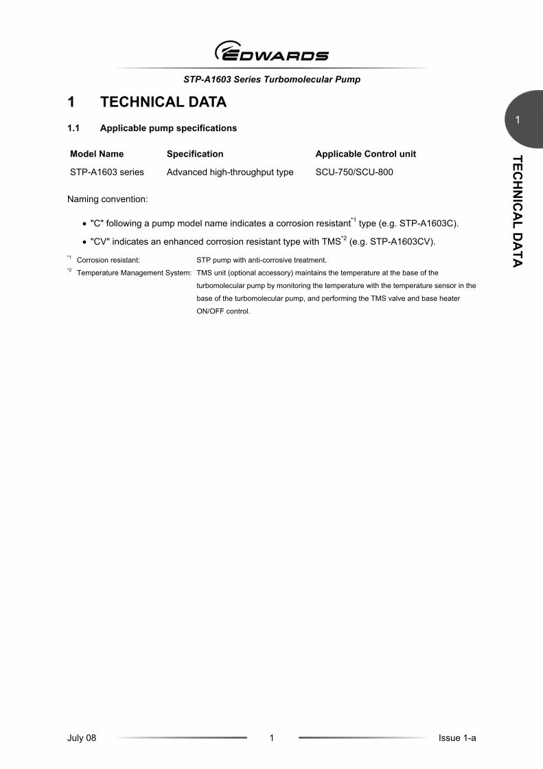
11 TECHNICAL DATA 1.1 Applicable pump specifications
Model Name Specification Applicable Control unit
STP-A1603 series Advanced high-throughput type SCU-750/SCU-800 Naming convention:
• "C" following a pump model name indicates a corrosion resistant*1 type (e.g. STP-A1603C).
• "CV" indicates an enhanced corrosion resistant type with TMS*2 (e.g. STP-A1603CV). *1 Corrosion resistant: STP pump with anti-corrosive treatment. *2 Temperature Management System: TMS unit (optional accessory) maintains the temperature at the base of the
turbomolecular pump by monitoring the temperature with the temperature sensor in the
base of the turbomolecular pump, and performing the TMS valve and base heater
ON/OFF control.

STP-A1603 Series Turbomolecular Pump
July 08 2 Issue 1-a
TECH
NIC
AL D
ATA
PAGE 2
1
1.1.1 STP pump specifications
The values shown below are typical. They are not guaranteed.
Item A1603 series
Inlet port flange ISO200F/VG200/ICF253 Flange size
Outlet port flange KF40
N2 L/s 1600 Pumping speed
H2 L/s 1200
N2 >108 Compression ratio
H2 7×10³
Ultimate pressure Pa (Torr) 10-7 (10-9) order [after baking]
Maximum gas flow rate*1 N2 Pa·m3/s(SCCM)
4.2 (2500): Water Cooling 1.7 (1000): TMS unit used (60 °C)
Ar Pa·m3/s(SCCM)
1.7 (1000): Water Cooling 0.8 (500): TMS unit used (60 °C)
Allowable backing pressure*1 Pa (Torr) 266 (2): Water cooling/TMS unit used
Flow rate of purge gas <N2> Pa·m3/s (SCCM)
3.4×10⁻² to 8.4×10⁻²
(20 to 50)
Rated speed rpm 36,500
Backup rotational speed*2 rpm Approximately 8,000
Starting time min 7
Stopping time min 9
Noise dB <50 (at 36,500 rpm)
Temperature Management System (TMS) Available
Baking temperature °C <120
Lubricating oil Not necessary
Installation position Free
Cooling method Water cooling
Recommended backing-pump L/min >1,300
Mass*3 kg 35
Ambient temperature range °C 0 to 40
Storage temperature range °C -25 to 55
Applicable Control unit SCU-750/SCU-800

STP-A1603 Series Turbomolecular Pump
July 08 3 Issue 1-a
TECH
NIC
AL D
ATA
1
*1 The pressure is applicable under conditions that N2 or other similar gas is vacuumed and the backing-pump (pumping
speed: 1,300 L/min) is used. When the gas is exhausted intermittently, the gas more than the maximum gas flow rate can be
exhausted. Consult Edwards about conditions. *2 A backup rotational speed is the lowest rotational speed to which the magnetic bearing can be backed up at a power failure. *3 Mass is a value of state that the only standard accessory was installed (except the optional accessory).
1.1.2 Condition for the water-cooling unit
Item Specification
Port type Rc 1/4 (Female) *1
Flow rate L/min 2
Water temperature °C 5 to 25
Water pressure MPa (kgf/cm2) 0.3 (3) *1 Standard type
1.2 External appearance of the STP pump
See the next page.

STP-A1603 Series Turbomolecular Pump
July 08 4 Issue 1-a
TECH
NIC
AL D
ATA
PAGE 4
1
A
(13)
φ270φ237
≧ 315
3510
.5
φ210
15゚
φ260
12-φ11
φ285φ300
8-φ15
φ270
22.5゚
20゚30゚
30゚35゚
25゚
147.
5
(175)
147
(9)
(10)
(8)
(11)
(5)(4)
(6)
129
16
262
276
.5
309
322
(3)
268.
5
303
.5
90
137
(1)(2)
(12)
(7)
16
Figure 1 - STP-A1603 series: ISO200F/VG200
No. Item Description
1 Inlet port flange ISO*2200F
2 Inlet port flange VG*1200
3 Height of the purge port
4 Bending dimension of the STP connection cable
5 Temperature sensor connector Optional accessory
6 Screw hole of legs M12*1 depth 20
7 Screw hole for legs M12*1 depth 24
8 Outlet port flange KF*140
9 Cooling water port 2-Rc*21/4
10 Purge port KF*110
11 STP connector
12 Screw hole for legs 8-M12*1 depth 24
13 Viewed from arrow A *1 JIS *2 ISO
STP-A1603 Series Turbomolecular Pump
July 08 5 Issue 1-a
TECH
NIC
AL D
ATA
1
A
(12)
φ270φ237
≧ 315
3510
.5φ210
20゚30゚
30゚35゚
25゚
147.
5
(175)
147
(8)
(9)
(7)
(10)
(4)(3)
(5)
167
300
314.
5
347
360 (2)3
06.5
341.
5
90
175
(1)
(11)
(6)
φ231.8
15゚24-φ8.47.5゚
φ253
25
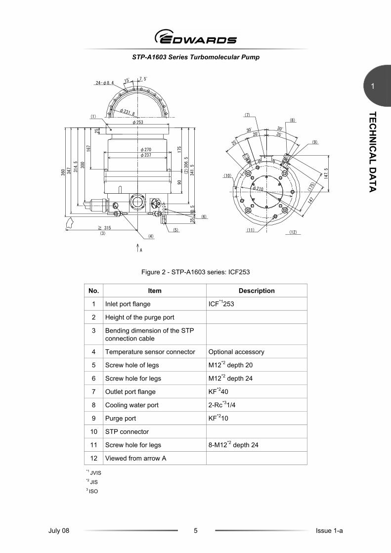
Figure 2 - STP-A1603 series: ICF253
No. Item Description
1 Inlet port flange ICF*1253
2 Height of the purge port
3 Bending dimension of the STP connection cable
4 Temperature sensor connector Optional accessory
5 Screw hole of legs M12*2 depth 20
6 Screw hole for legs M12*2 depth 24
7 Outlet port flange KF*240
8 Cooling water port 2-Rc*31/4
9 Purge port KF*210
10 STP connector
11 Screw hole for legs 8-M12*2 depth 24
12 Viewed from arrow A
*1 JVIS *2 JIS 3 ISO
STP-A1603 Series Turbomolecular Pump
July 08 6 Issue 1-a
TECH
NIC
AL D
ATA
PAGE 6
1
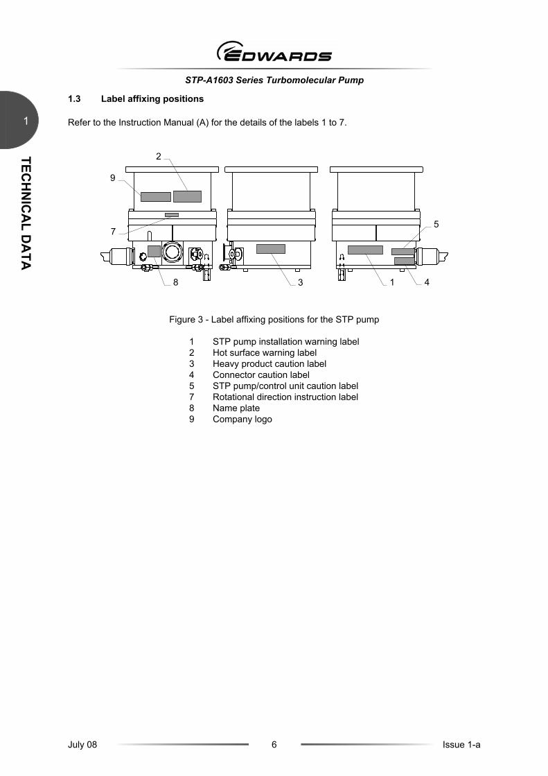
1.3 Label affixing positions
Refer to the Instruction Manual (A) for the details of the labels 1 to 7.
Figure 3 - Label affixing positions for the STP pump
1 STP pump installation warning label2 Hot surface warning label 3 Heavy product caution label 4 Connector caution label 5 STP pump/control unit caution label7 Rotational direction instruction label8 Name plate 9 Company logo
9
2
8 3 1
5 7
4
STP-A1603 Series Turbomolecular Pump
July 08 7 Issue 1-a
TECH
NIC
AL D
ATA
1
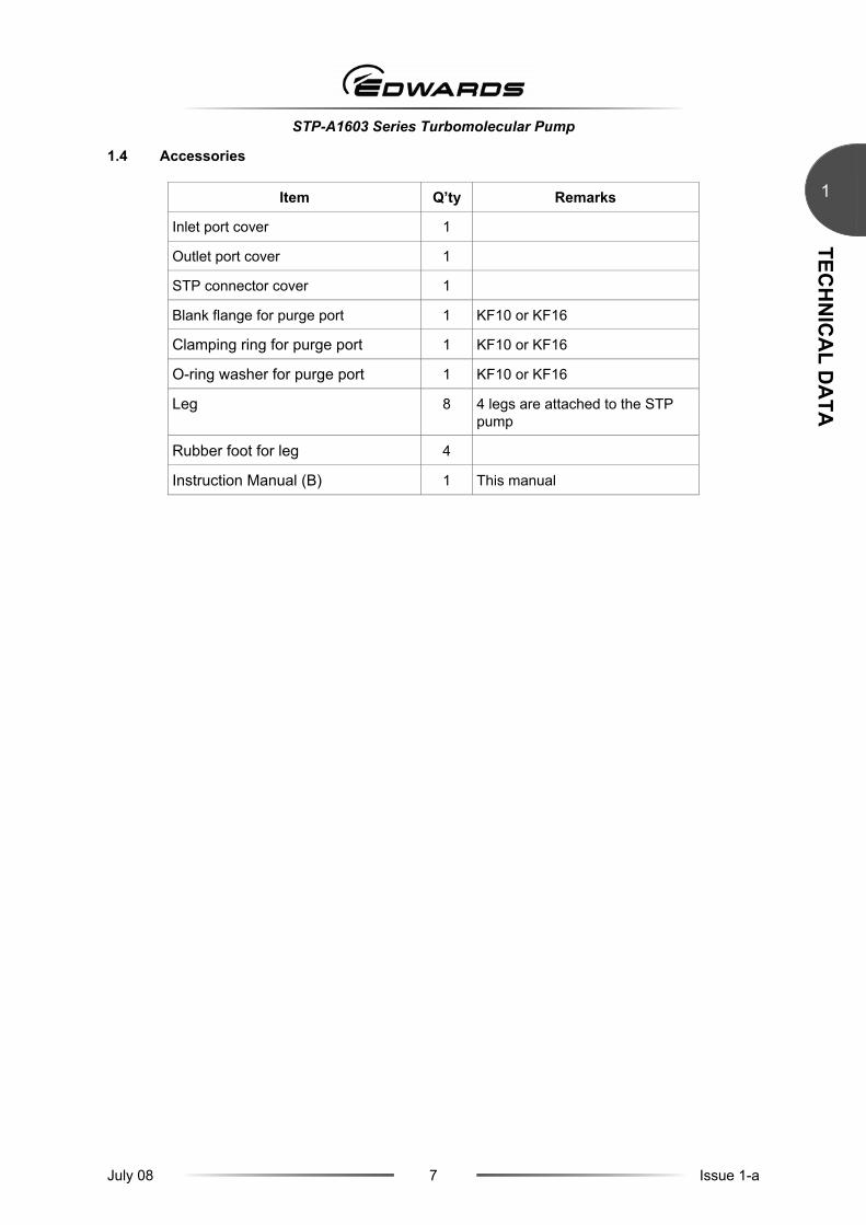
1.4 Accessories
Item Q’ty Remarks
Inlet port cover 1
Outlet port cover 1
STP connector cover 1
Blank flange for purge port 1 KF10 or KF16
Clamping ring for purge port 1 KF10 or KF16
O-ring washer for purge port 1 KF10 or KF16
Leg 8 4 legs are attached to the STP pump
Rubber foot for leg 4
Instruction Manual (B) 1 This manual

STP-A1603 Series Turbomolecular Pump
July 08 8 Issue 1-a
TECH
NIC
AL D
ATA
PAGE 8
1
This page intentionally blank.

STP-A1603 Series Turbomolecular Pump
July 08 9 Issue 1-a
HO
W TO
SECU
RE TH
E STP PUM
P
22 HOW TO SECURE THE STP PUMP
WARNING
The STP pump is provided with a high-speed rotor. Any internal abnormality/error may result in a jump in rotational torque leading to personal injury or peripheral
equipment damage. The STP pump is provided with a high-speed rotor. The worst-case failure may result in a jump in rotational torque leading to personal injury or peripheral equipment damage.
The method of securing the STP pump will depend on the installation requirements. Secure the STP pump to the vacuum equipment as follows:
Design and secure the mounting for the STP pump so that it can withstand the maximum rotational torque. Refer to Table 2 for torque in pump abnormality.
In some cases, the damper and the claw clamper securing cannot be used.
This will depend on the type of STP pump. Refer to Table 1 for torque tightening the bolts used.
Bolt size Tightening torque (Nm)
M8 12
M10 24
M12 42
Table 1 - Tightening torque of bolt
When making the legs to secure the base, make them shorter than the ones attached to the STP pump. Use a material that has a tensile strength of 600N/mm2 or more.
When securing the base, use stainless steel securing bolts with a tensile strength class of 70 or more.
Note: When using any securing method other than that specified in this manual, contact Edwards.
Damper
Yes
No
With bolts
With claw clamps
Secure the inlet port
Refer to Section 2.1
Refer to Section 2.2
Refer to Section 2.3

STP-A1603 Series Turbomolecular Pump
July 08 10 Issue 1-a
HO
W TO
SECU
RE TH
E STP PUM
P
2
2.1 When securing the inlet port with bolts
Refer to Table 2 for maximum predicted torque in any pump abnormality and for the recommended type of securing bolt for inlet port flange.
Secure the inlet port flange with the correct size bolts as specified in the Inlet Port Flange Standard.
Secure the base with either the 8 screws for legs or the 8 attached legs. Ensure instructions with regard to legs and bolts for securing the base are adhered to page 9. Make sure that the recommended securing bolt is the correct one depending on the method of securing the base.
Pump mode STP-A1603 series
Flange type ISO200F*2 VG200 ICF253
Torque in pump abnormality [Nm] 4.0×10⁴ 4.0×10⁴ 4.0×10⁴
Base (8 positions) securing No Yes No Yes No Yes
Shape Standard Standard Standard Standard Standard Standard
Material*1 Carbon steel Alloyed steel Stainless steel Carbon steel
Alloyed steel Stainless steel Carbon steel Alloyed steel Stainless steel
Recommended securing bolt for
flange Strength*1 12.9 or more 70 or more 12.9 or more 70 or more 12.9 or more 70 or more
*1 Refer to ISO898-1 (JISB 1051), ISO3506 (JISB 1054) and AMS6419 (Aerospace Material Specification). *2 Maximum predicted torque of ISO flange type pump is the same as that of ISO_F flange type pump.
Table 2 - Maximum torque predicted and recommended securing bolt for inlet port flange
(A) When the base is not secured (B) When the base is secured
1. Recommended fitting bolt for flange
2. Secure the base
Figure 4 - Example of securing the STP pump (when securing the inlet port with bolts)
1
2

STP-A1603 Series Turbomolecular Pump
July 08 11 Issue 1-a
HO
W TO
SECU
RE TH
E STP PUM
P
2
2.2 When securing the inlet port flange with claw clamps
Refer to Table 2 for rotational torque.
When securing the inlet port flange with only the claw clamp, the vacuum equipment cannot withstand the maximum rotational torque generated by the worst-case failure. To make the vacuum equipment withstand abnormal torque, secure the base with either the 8 screws for legs or the 8 attached legs. Ensure instructions with regard to legs and bolts for securing the base are adhered to page 9.
For the claw clamp-type, use the required number of claw clamps as specified in Table 3. Position the claw clamps evenly on the circumference.
Flange size Number of Claw Clamps
ISO 160 or less 4 or more
ISO 200 to 250 6 or more
ISO 320 or more 8 or more
Table 3 - Number of claw clamps for flange size
1. Vacuum equipment
2. Claw clamps
3. Secure the base
Figure 5 - Example of securing the STP pump (when securing the inlet port flange with claw clamps)
1
2
3
STP-A1603 Series Turbomolecular Pump
July 08 12 Issue 1-a
HO
W TO
SECU
RE TH
E STP PUM
P
2
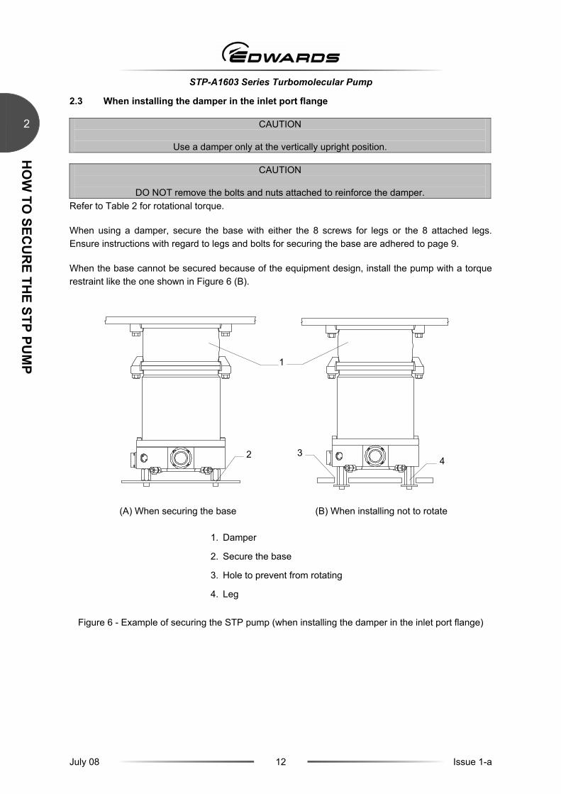
2.3 When installing the damper in the inlet port flange
CAUTION
Use a damper only at the vertically upright position.
CAUTION
DO NOT remove the bolts and nuts attached to reinforce the damper. Refer to Table 2 for rotational torque.
When using a damper, secure the base with either the 8 screws for legs or the 8 attached legs. Ensure instructions with regard to legs and bolts for securing the base are adhered to page 9.
When the base cannot be secured because of the equipment design, install the pump with a torque restraint like the one shown in Figure 6 (B).
(A) When securing the base (B) When installing not to rotate
1. Damper
2. Secure the base
3. Hole to prevent from rotating
4. Leg
Figure 6 - Example of securing the STP pump (when installing the damper in the inlet port flange)
1
2 34
STP-A1603 Series Turbomolecular Pump
July 08 13 Issue 1-a
TEMPER
ATU
RE M
AN
AG
EMEN
T SYSTEM
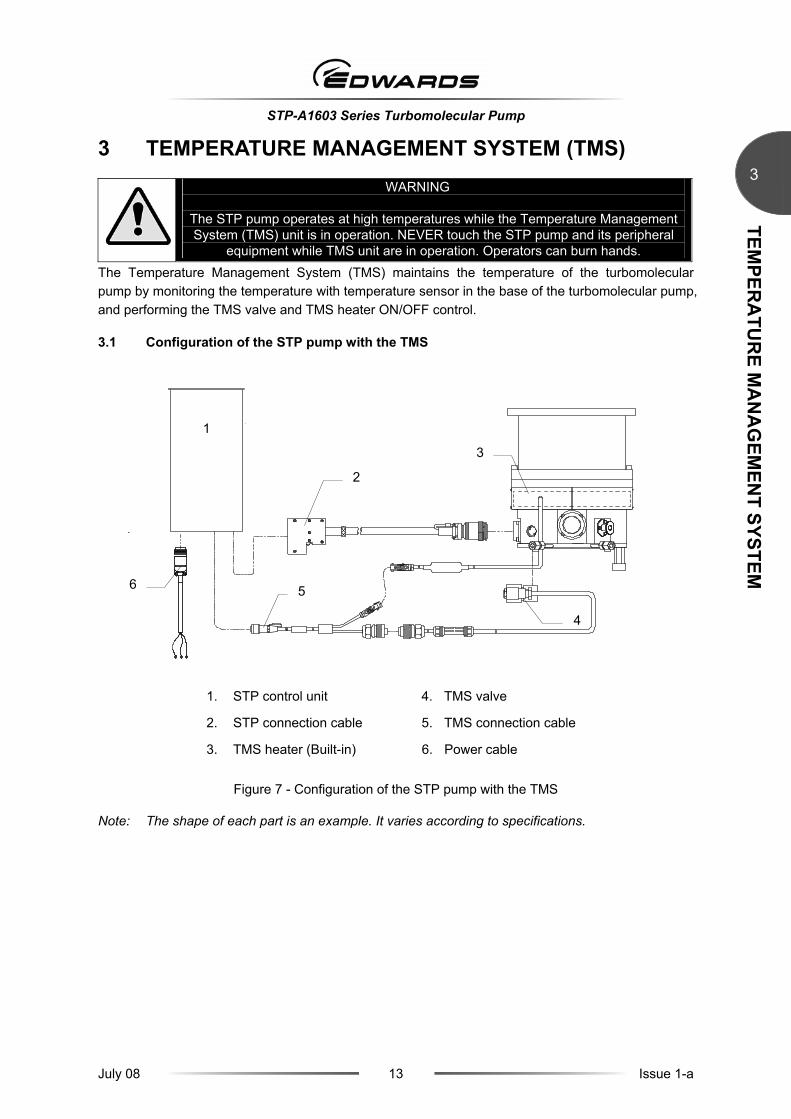
33 TEMPERATURE MANAGEMENT SYSTEM (TMS)
WARNING
The STP pump operates at high temperatures while the Temperature Management System (TMS) unit is in operation. NEVER touch the STP pump and its peripheral
equipment while TMS unit are in operation. Operators can burn hands. The Temperature Management System (TMS) maintains the temperature of the turbomolecular pump by monitoring the temperature with temperature sensor in the base of the turbomolecular pump, and performing the TMS valve and TMS heater ON/OFF control.
3.1 Configuration of the STP pump with the TMS
1. STP control unit 4. TMS valve
2. STP connection cable 5. TMS connection cable
3. TMS heater (Built-in) 6. Power cable
Figure 7 - Configuration of the STP pump with the TMS
Note: The shape of each part is an example. It varies according to specifications.
2
1
3
4
5 6
STP-A1603 Series Turbomolecular Pump
July 08 14 Issue 1-a
TEMPER
ATU
RE M
AN
AG
EMEN
T SYSTEM
3
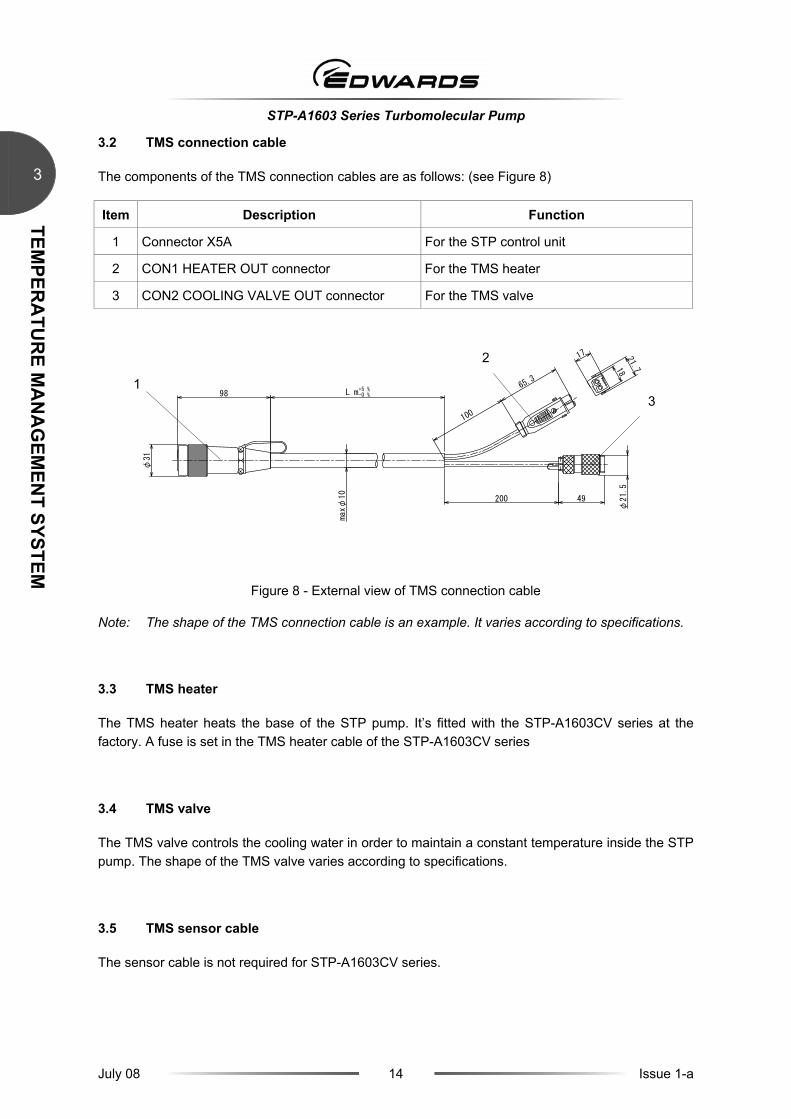
3.2 TMS connection cable
The components of the TMS connection cables are as follows: (see Figure 8)
Item Description Function
1 Connector X5A For the STP control unit
2 CON1 HEATER OUT connector For the TMS heater
3 CON2 COOLING VALVE OUT connector For the TMS valve
65.3
17
1821.7
49
φ21.
5
98
φ31
L m+5 %-0 %
100
200
maxφ
10
Figure 8 - External view of TMS connection cable
Note: The shape of the TMS connection cable is an example. It varies according to specifications.
3.3 TMS heater
The TMS heater heats the base of the STP pump. It’s fitted with the STP-A1603CV series at the factory. A fuse is set in the TMS heater cable of the STP-A1603CV series
3.4 TMS valve
The TMS valve controls the cooling water in order to maintain a constant temperature inside the STP pump. The shape of the TMS valve varies according to specifications.
3.5 TMS sensor cable
The sensor cable is not required for STP-A1603CV series.
1
2
3

STP-A1603 Series Turbomolecular Pump
July 08 15 Issue 1-a
TEMPER
ATU
RE M
AN
AG
EMEN
T SYSTEM
3
3.6 Installation of the TMS unit
CAUTION
DO NOT install the TMS unit in places with high temperature, humidity, noise, vibration, or other unstable environment.
CAUTION
DO NOT apply force to the TMS unit and cables during installation and DO NOT bend the cables
excessively.
3.6.1 Connecting the TMS connection cable to the STP control unit
Insert the connector X5A of the TMS connection cable into the connector X5 of the STP control unit. (see the "STP control unit Instruction Manual (C)" for the position of the connector X5.)
3.6.2 Connecting the pump and TMS valve
Refer to Figure 7, "Configuration of the STP pump with the TMS".
Connect the cooling water pipe to the TMS valve. Pay special attention to the port label on the cooling water valve to connect proper port. Connect the NC side (or OUT side) of the TMS valve to the STP pump, and COM side (or IN side) of the TMS valve to the equipment.
Use cooling water under the conditions in Section 3.8, “Condition for the TMS unit”.
Note: Procure and connect the cooling water pipe and affix the electromagnetic cooling water valve at your site.
3.6.3 Connecting TMS connection cable to STP pumps
Refer to Figure 7, "Configuration of the TMS unit". Connect the TMS connection cable to the STP pump as follows:
1. Connect the cable for the TMS heater to the "CON1 HEATER OUT" of the TMS connection cable.
2. Connect the cable for the TMS valve to the "CON2 COOLING VALVE OUT" connector of the TMS connection cable.

STP-A1603 Series Turbomolecular Pump
July 08 16 Issue 1-a
TEMPER
ATU
RE M
AN
AG
EMEN
T SYSTEM
3
3.7 Replacing the fuses in the TMS connection cable
Fuses for the TMS valve and the TMS heater of STP-A1603CV series are set inside the TMS connection cable. Contact the Service office, when replacement is required.
3.8 Condition for the TMS unit
Item Condition
Ambient temperature range °C 0 to 40
Storage temperature range °C -20 to 55
Input voltage Same voltage as the STP control unit 200 to 240 Vac
Temperature control method Control ON/OFF of the TMS heater and cooling water
Setting temperature °C Standard type: 60
Cooling water temperature °C 5 to 25
Quantity of cooling water flow
L/min 2
Alarm output Alarm outputs from the STP control unit
Electric leakage protection (Only with ELB type)
Protected by Earth Leakage Breaker on the TMS heater primary side (Sensed current: 15 mA, operating time: within 0.1 second)
3.9 Accessories
Item Q’ty Condition
TMS heater 1 Built-in
TMS connection cable 1 With connector at each end
TMS valve 1 Cable with connector on one side
Copyright 2008 Edwards Japan Limited. All rights reserved.
For more information, contact the nearest Service Office.
Manufacturer: Edwards Japan Limited
1078-1, Yoshihashi, Yachiyo-shi, Chiba 276-8523 JAPAN Telephone: Domestic 047-458-8822
International +81-47-458-8822 Facsimile: Domestic 047-458-8833 International +81-47-458-8833
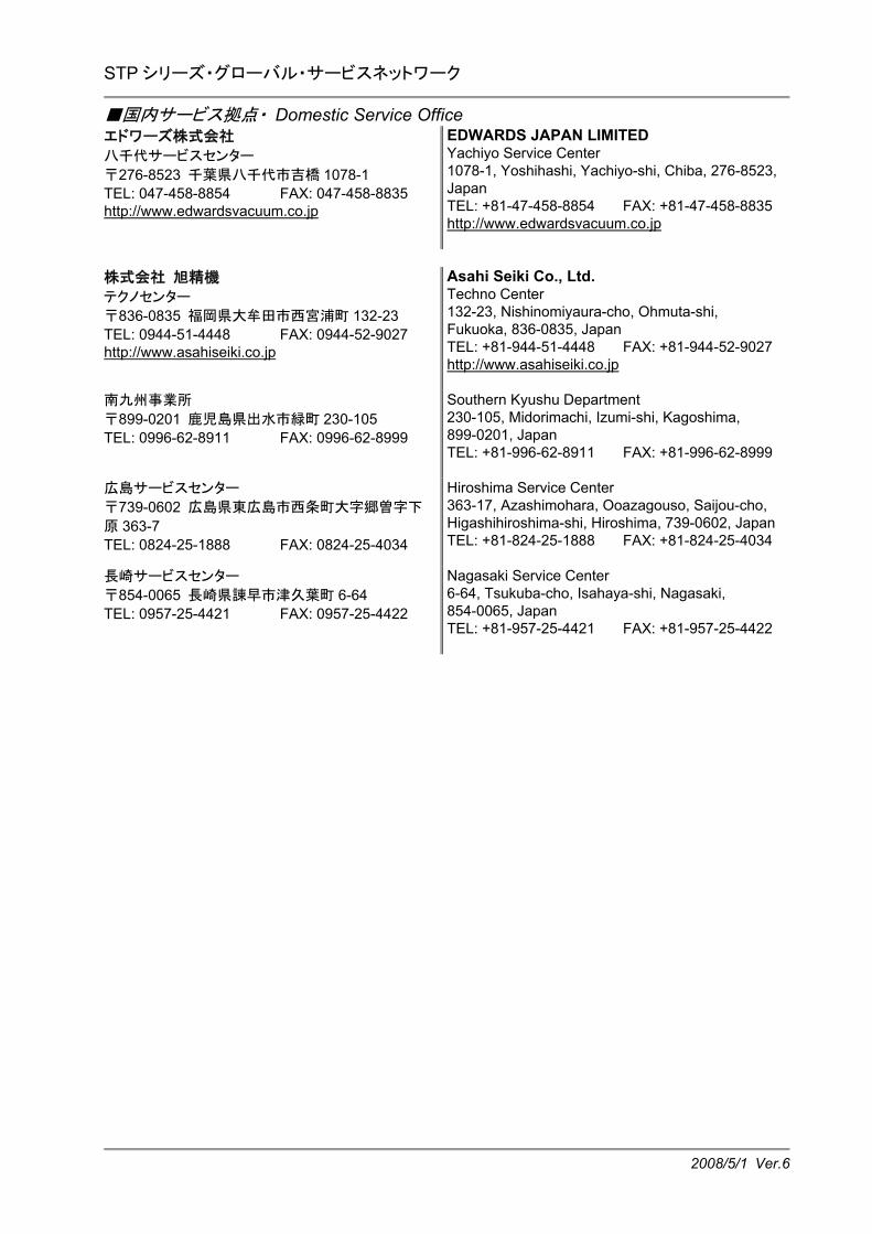
STP シリーズ・グローバル・サービスネットワーク
2008/5/1 Ver.6
■国内サービス拠点・ Domestic Service Office エドワーズ株式会社 八千代サービスセンター 〒276-8523 千葉県八千代市吉橋 1078-1 TEL: 047-458-8854 FAX: 047-458-8835 http://www.edwardsvacuum.co.jp
EDWARDS JAPAN LIMITED Yachiyo Service Center 1078-1, Yoshihashi, Yachiyo-shi, Chiba, 276-8523, Japan TEL: +81-47-458-8854 FAX: +81-47-458-8835http://www.edwardsvacuum.co.jp
株式会社 旭精機 テクノセンター 〒836-0835 福岡県大牟田市西宮浦町 132-23 TEL: 0944-51-4448 FAX: 0944-52-9027 http://www.asahiseiki.co.jp
Asahi Seiki Co., Ltd. Techno Center 132-23, Nishinomiyaura-cho, Ohmuta-shi, Fukuoka, 836-0835, Japan TEL: +81-944-51-4448 FAX: +81-944-52-9027http://www.asahiseiki.co.jp
南九州事業所 〒899-0201 鹿児島県出水市緑町 230-105 TEL: 0996-62-8911 FAX: 0996-62-8999
Southern Kyushu Department 230-105, Midorimachi, Izumi-shi, Kagoshima, 899-0201, Japan TEL: +81-996-62-8911 FAX: +81-996-62-8999
広島サービスセンター 〒739-0602 広島県東広島市西条町大字郷曽字下
原 363-7 TEL: 0824-25-1888 FAX: 0824-25-4034
Hiroshima Service Center 363-17, Azashimohara, Ooazagouso, Saijou-cho, Higashihiroshima-shi, Hiroshima, 739-0602, JapanTEL: +81-824-25-1888 FAX: +81-824-25-4034
長崎サービスセンター 〒854-0065 長崎県諌早市津久葉町 6-64 TEL: 0957-25-4421 FAX: 0957-25-4422
Nagasaki Service Center 6-64, Tsukuba-cho, Isahaya-shi, Nagasaki, 854-0065, Japan TEL: +81-957-25-4421 FAX: +81-957-25-4422

STP Series / Global Service Network
2008/5/1 Ver.6
■Oversea Service OfficeUnited Kingdom EDWARDS World Headquarters Manor Royal, Crawley, West Sussex, RH10 9LW, United Kingdom TEL: +44-1293-528844 FAX: +44-1293 533453http://www.edwardsvacuum.com France EDWARDS 125 Avenue Louis Roche, 92238 Gennevilliers, Cedex, Paris, France TEL: +33-1-4798-2401 FAX: +33-1-4798-4454 Germany EDWARDS Ammerthalstrasse 36, 85551 Kirchheim, Munich, Germany TEL: +49-89-9919180 FAX: +49-89-99191840 Italy EDWARDS Via Carpaccio 35, 20090 Trezzano Sul Naviglio, Milan, Italy TEL: +39-02-48-4471 FAX: +39-02-48-401638 Wilmington/USA EDWARDS North American Headquarters 301 Ballardvale Street, Wilmington, MA 01887, USATEL: +1-978-658-5410 FAX: +1-978-658-7969 Santa Clara/USA EDWARDS 2041 Mission College Blvd, Suite 260, Santa Clara, CA 95054, USA TEL: +1-408-496-1177 FAX: +1-408-496-1188 Austin/USA EDWARDS 8201 East Riverside Drive, Building 4, Suite 125, Austin, TX 78744, USA TEL: +1-512-694-7259 FAX: +1-512-389-3378 Israel EDWARDS ISRAEL VACUUM LTD 5 Habarzel Blvd Gat 2000 Industrial Zone Qiryat Gat82000, Israel TEL: +972-7-6810633 FAX: +972-7-6810640
Korea Edwards Korea Limited Chunan A/S Center 625-7 Upsung-Dong, Cheonan City, ChungchongNam-do, Korea, 330-290 TEL: +82-41-621-7070 FAX: +82-41-621-7700 Korea Edwards Korea Limited Headquarters 5Fl, Hanwon Bldg, 6-1 Sunae-dong, Bundang-gu, Seongnam-si, Gyeoriggi-do, Korea TEL: +82-31-716-7070 FAX: +82-31-710-2223 Singapore Edwards Technologies Singapore Pte Limited42 Loyang Drive, Loyang Industrial Estate, Singapore 508962 TEL: +65-6546-8408 FAX: +65-6546-8407 China Edwards Technologies Trading (Shanghai) Co.,Ltd 23 Fu Te Road(N), Wai Gao Qiao Free Trade Zone, Pudong, Shanghai, 200131, PRC. China TEL: +86-21-5866-9618 FAX: +86-21-5866-9993 Taiwan HIGHLIGHT TECH CORP. Tainan Service Center/Headquarters No. 106, Gung-Min South Road II An-Nan Area, Tainan City, Taiwan 709 TEL: +886-6-2460296 FAX: +886-6-2471701 http://www.high-light.com.tw Taiwan HIGHLIGHT TECH CORP. Hsinchu Service Center No. 8, Guangfu S. Rd., Fenghuang Tsuen, Hukou Shiang, Hsinchu, Taiwan 303 TEL: +886-3-5973325 FAX: +886-3-5973083 India EDWARDS 203 Surya Kiran Building, 19 Kasturba Gandhi Marg, New Delhi, India 110 001 TEL: +91-11-4151-0065 FAX: +91-11-4151-0245
Return of Edwards Equipment - Procedure
Form HS1
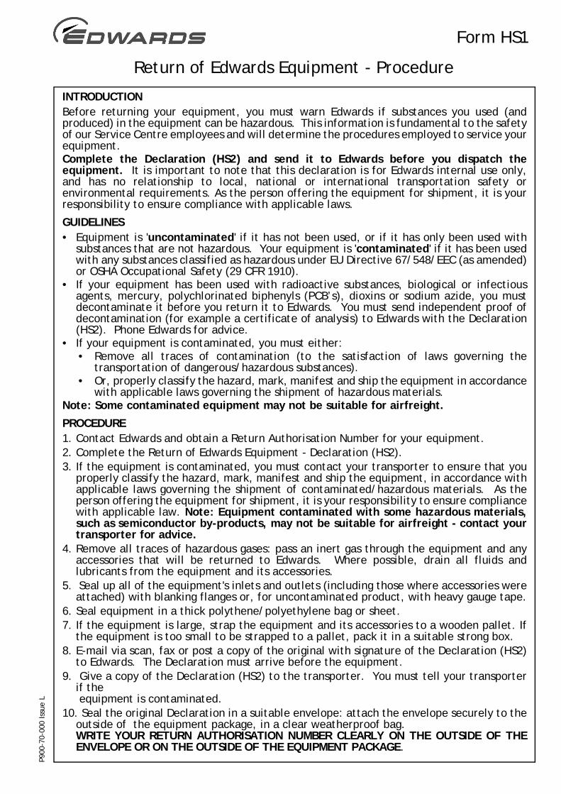
INTRODUCTIONBefore returning your equipment, you must warn Edwards if substances you used (andproduced) in the equipment can be hazardous. This information is fundamental to the safetyof our Service Centre employees and will determine the procedures employed to service yourequipment.Complete the Declaration (HS2) and send it to Edwards before you dispatch theequipment. It is important to note that this declaration is for Edwards internal use only,and has no relationship to local, national or international transportation safety orenvironmental requirements. As the person offering the equipment for shipment, it is yourresponsibility to ensure compliance with applicable laws.
GUIDELINES• Equipment is 'uncontaminated' if it has not been used, or if it has only been used with
substances that are not hazardous. Your equipment is 'contaminated' if it has been usedwith any substances classified as hazardous under EU Directive 67/548/EEC (as amended)or OSHA Occupational Safety (29 CFR 1910).
• If your equipment has been used with radioactive substances, biological or infectiousagents, mercury, polychlorinated biphenyls (PCB’s), dioxins or sodium azide, you mustdecontaminate it before you return it to Edwards. You must send independent proof ofdecontamination (for example a certificate of analysis) to Edwards with the Declaration(HS2). Phone Edwards for advice.
• If your equipment is contaminated, you must either:• Remove all traces of contamination (to the satisfaction of laws governing the
transportation of dangerous/hazardous substances).• Or, properly classify the hazard, mark, manifest and ship the equipment in accordance
with applicable laws governing the shipment of hazardous materials.Note: Some contaminated equipment may not be suitable for airfreight.
PROCEDURE1. Contact Edwards and obtain a Return Authorisation Number for your equipment.2. Complete the Return of Edwards Equipment - Declaration (HS2).3. If the equipment is contaminated, you must contact your transporter to ensure that you
properly classify the hazard, mark, manifest and ship the equipment, in accordance withapplicable laws governing the shipment of contaminated/hazardous materials. As theperson offering the equipment for shipment, it is your responsibility to ensure compliancewith applicable law. Note: Equipment contaminated with some hazardous materials,such as semiconductor by-products, may not be suitable for airfreight - contact yourtransporter for advice.
4. Remove all traces of hazardous gases: pass an inert gas through the equipment and anyaccessories that will be returned to Edwards. Where possible, drain all fluids andlubricants from the equipment and its accessories.
5. Seal up all of the equipment's inlets and outlets (including those where accessories wereattached) with blanking flanges or, for uncontaminated product, with heavy gauge tape.
6. Seal equipment in a thick polythene/polyethylene bag or sheet.7. If the equipment is large, strap the equipment and its accessories to a wooden pallet. If
the equipment is too small to be strapped to a pallet, pack it in a suitable strong box.8. E-mail via scan, fax or post a copy of the original with signature of the Declaration (HS2)
to Edwards. The Declaration must arrive before the equipment.9. Give a copy of the Declaration (HS2) to the transporter. You must tell your transporter
if the equipment is contaminated.
10. Seal the original Declaration in a suitable envelope: attach the envelope securely to theoutside of the equipment package, in a clear weatherproof bag.WRITE YOUR RETURN AUTHORISATION NUMBER CLEARLY ON THE OUTSIDE OF THEENVELOPE OR ON THE OUTSIDE OF THE EQUIPMENT PACKAGE.
P900
-70-
000
Issu
e L

Return of Edwards Equipment – Declaration
Form HS2
You must:• Know about all of the substances which have been used and produced in the equipment before you complete this Declaration• Read the Return of Edwards Equipment – Procedure (HS1) before you complete this Declaration• Contact Edwards to obtain a Return Authorisation Number and to obtain advice if you have any questions• Send this form to Edwards before you return your equipment as per the procedure in HS1
Return Authorisation Number:
Manufacturer's Product Name ________________________
Manufacturer's Part Number _________________________
Manufacturer's Serial Number ________________________
Has the equipment been used, tested or operated?
YES Go to Section 2 NO Go to Section 4
IF APPLICABLE:Tool Reference Number _____________________
Process _______________________________________
Failure Date _______________________________
Serial Number ofReplacement Equipment ______________________
Are any substances used or produced in the equipment:
• Radioactive, biological or infectious agents, mercury, poly chlorinated biphenyls (PCBs), dioxins or sodium azide? (if YES, see Note 1) YES NO
• Hazardous to humanhealth and safety? YES NO
Note 1: Edwards will not accept delivery of any equipment that is contaminated with radioactive substances, biological/infectious agents, mercury, PCB’s, dioxins or sodium azide, unless you:
• Decontaminate the equipment• Provide proof of decontaminationYOU MUST CONTACT EDWARDS FOR ADVICE BEFORE YOU RETURN SUCH EQUIPMENT
Print your name: _________________________________ Print your job title: ____________________________________
Print your organisation: ____________________________________________________________________________________
Print your address: _____________________________________________________________________________________
_____________________________________________________________________________________________________Telephone number: ___________________________ Date of equipment delivery: ____________________________________
I have made reasonable enquiry and I have supplied accurate information in this Declaration. I have not withheld any information, and I have followed the Return ofEdwards Equipment – Procedure (HS1).
Signed: _____________________________________ Date: ______________
• who did you buy the equipment from? __________________________________
• give the supplier’s invoice number __________________________________If you have a warranty claim:
Substance name ChemicalSymbol
Precautions required (for example,use protective gloves, etc.)
Action required after a spill,leak or exposure
Note: Please print out this form, sign it and return the signed form as hard copy.
SECTION 1: EQUIPMENT
SECTION 2: SUBSTANCES IN CONTACT WITH THE EQUIPMENT
SECTION 3: LIST OF SUBSTANCES IN CONTACT WITH THE EQUIPMENT
SECTION 4: RETURN INFORMATION
SECTION 5: DECLARATION
P900
-71-
000
Issu
e M
Reason for return and symptoms of malfunction: ____________________________________________________________
______________________________________________________________________________________________________