view journal lab on a chip - mcgill university on a chip view article online view journal this...
TRANSCRIPT

Registered Charity Number 207890
Accepted Manuscript
This is an Accepted Manuscript, which has been through the RSC Publishing peer review process and has been accepted for publication.
Accepted Manuscripts are published online shortly after acceptance, which is prior to technical editing, formatting and proof reading. This free service from RSC Publishing allows authors to make their results available to the community, in citable form, before publication of the edited article. This Accepted Manuscript will be replaced by the edited and formatted Advance Article as soon as this is available.
To cite this manuscript please use its permanent Digital Object Identifier (DOI®), which is identical for all formats of publication.
More information about Accepted Manuscripts can be found in the Information for Authors.
Please note that technical editing may introduce minor changes to the text and/or graphics contained in the manuscript submitted by the author(s) which may alter content, and that the standard Terms & Conditions and the ethical guidelines that apply to the journal are still applicable. In no event shall the RSC be held responsible for any errors or omissions in these Accepted Manuscript manuscripts or any consequences arising from the use of any information contained in them.
www.rsc.org/loc
Lab on a ChipView Article OnlineView Journal
This article can be cited before page numbers have been issued, to do this please use: R. Safavieh and D. Juncker, Lab Chip,2013, DOI: 10.1039/C3LC50691F.
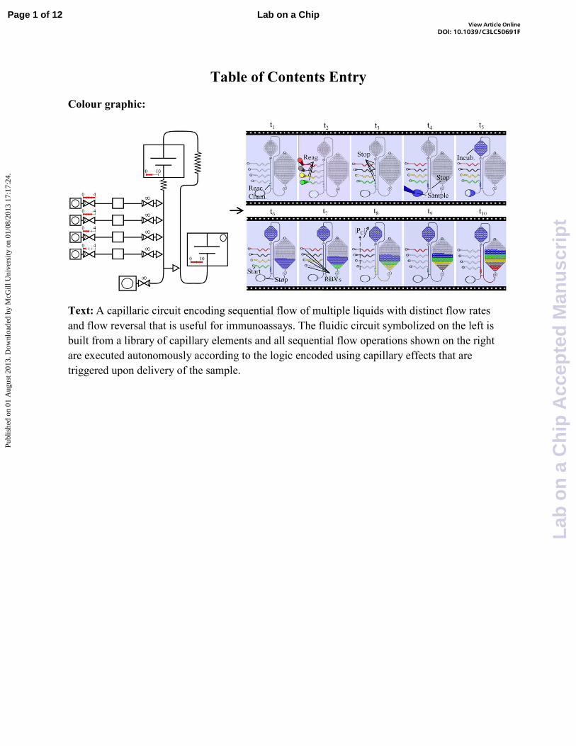
Table of Contents Entry
Colour graphic:
Text: A capillaric circuit encoding sequential flow of multiple liquids with distinct flow rates
and flow reversal that is useful for immunoassays. The fluidic circuit symbolized on the left is
built from a library of capillary elements and all sequential flow operations shown on the right
are executed autonomously according to the logic encoded using capillary effects that are
triggered upon delivery of the sample.
Page 1 of 12 Lab on a Chip
Lab
on
a C
hip
Acc
epte
d M
anu
scri
pt
Publ
ishe
d on
01
Aug
ust 2
013.
Dow
nloa
ded
by M
cGill
Uni
vers
ity o
n 01
/08/
2013
17:
17:2
4.
View Article OnlineDOI: 10.1039/C3LC50691F

Journal Name
Cite this: DOI: 10.1039/c0xx00000x
www.rsc.org/xxxxxx
Dynamic Article Links ►
ARTICLE TYPE
This journal is © The Royal Society of Chemistry [year] [journal], [year], [vol], 00–00 | 1
Capillarics: Pre-Programmed, Self-Powered Microfluidic Circuits Built
From Capillary Elements
Roozbeh Safavieh, ab and David Juncker*
abc
Received (in XXX, XXX) Xth XXXXXXXXX 20XX, Accepted Xth XXXXXXXXX 20XX
DOI: 10.1039/b000000x 5
Microfluidic capillary systems employ surface tension effects to manipulate liquids, and are thus
self-powered and self-regulated as liquid handling is structurally and chemically encoded in microscale
conduits. However, capillary systems have been limited to perform simple fluidic operations. Here, we
introduce complex capillary flow circuits that encode sequential flow of multiple liquids with distinct
flow rates and flow reversal. We first introduce two novel microfluidic capillary elements including (i) 10
retention burst valves and (ii) robust low aspect ratio trigger valves. These elements are combined with
flow resistors, capillary retention valves, capillary pumps, and open and closed reservoirs to build a
capillary circuit that following sample addition, autonomously delivers a defined sequence of multiple
chemicals according to a preprogrammed and predetermined flow rate and time. Such a circuit was used
to measure the concentration of C-reactive protein. This work illustrates that as in electronics, complex 15
capillary circuits may be built by combining simple capillary elements. We define such circuits as
“capillarics”, and introduce symbolic representations. We believe that more complex circuits will become
possible by expanding the library of building elements and formulating abstract design rules.
Introduction Lab on a Chip (LOC) devices have emerged as a powerful tool 20
for a variety of applications including bio-analysis1, 2 and point
of care diagnosis.3 Central to microfluidic applications is the
control of liquid flow within microconduits. Most microfluidic
systems depend on peripheral equipment to effect and control the
flow of liquid. As the complexity of these circuits increased, the 25
similarities to electronic circuits were exploited, most notably in
electrokinetic and electrophoretic microfluidics. In addition,
centrifugal and hydrophobic microfluidic systems were also built
where the advancement of the liquid was controlled by a
combination of external control, and pre-embedded restrictions 30
and hydrophobic patches.4 The most complex microfluidic
circuits developed to date are the ones made by multilayer soft
lithography.5 More recently, digital microfluidics that use
electrical fields and capacitances to move droplets on arrays of
electrodes, effectively create a connection between electronics 35
and microfluidics, which may facilitate subsequent scaling up.6
Owing to the great complexity of active microfluidic systems,
abstract level of representation were developed.7, 8 Passive
microfluidics, which have not been developed to the same level
of complexity, have not been represented at a symbolic level. 40
Here, we first briefly review passive microfluidics in this
introduction, and then present novel capillary fluidic elements
and their use for making an advanced capillary microfluidic
circuit; moreover, we propose a symbolic representation of
capillary elements (see Table 1) to facilitate the representation 45
and design of capillary circuits.
Passive and capillary microfluidics
So-called passive microfluidic systems circumvent the need for
peripheral equipment and extract the energy to move the liquids 50
from the system, thus only requiring minimal user interventions.
The flow in passive microfluidics is typically driven by capillary
effects, and they have in fact long been used in diagnostics in
lateral flow tests.9 Recently, paper-based microfluidics have
attracted renewed interest from academia and microfluidic 55
circuits with channels and reservoirs patterned in a paper or
nitrocellulose substrate using photolithography, printing or laser
cutting are being developed.10 To advance the functionality of
these circuits, various valves including (i) flow rate regulators by
patterning dilute solutions of a water soluble wax,11 or sugar 60
barriers12 in paper, and (ii) metering valves using sugar bridges12
or expandable polymer actuators13 combined in paper have been
developed to control the timing of the fluid delivery. In addition,
we and others showed that thread and yarn can be used to build
fluidic circuits from the bottom up14 and can be used for 65
immunoassays.15
The heterogeneity of fibrous microfluidics however makes
miniaturization difficult, implying that larger samples are
required, and multiplexing will be limited. Furthermore, the limit
of detection of paper and thread based microfluidics doesn’t 70
match the performance of classical ELISA and microfabricated
microfluidic systems until now.
Autonomous capillary microfluidic systems
A landmark paper by Delamarche and colleagues highlighted the 75
potential of self-filling microfluidics based on capillary effects.16
Page 2 of 12Lab on a Chip
Lab
on
a C
hip
Acc
epte
d M
anu
scri
pt
Publ
ishe
d on
01
Aug
ust 2
013.
Dow
nloa
ded
by M
cGill
Uni
vers
ity o
n 01
/08/
2013
17:
17:2
4.
View Article OnlineDOI: 10.1039/C3LC50691F

2 | Journal Name, [year], [vol], 00–00 This journal is © The Royal Society of Chemistry [year]
Arrays of hydrophilic 2 µm-wide microfluidic channels, formed
by sealing structured poly(dimethlsiloxane) (PDMS) onto silicon
wafers, were used to spontaneously draw in liquids into the
conduits and pattern proteins on surfaces; however, solutions
could not be rinsed or exchanged. Common chemical and 5
biochemical reactions do require addition and exchange of
multiple solutions in sequence. An autonomous microfluidic
capillary system (AMCS) that was self-powered and
self-regulated – hence autonomous – was proposed and designed
by combining a capillary pump (CP) and a capillary retention 10
valve (CRV).17 In AMCSs the capillary pressure is encoded in
the geometry and surface properties (free surface energy of both
solid surface and the liquid), which drives and controls the liquid
flow on the chip. AMCS allows filling and flushing multiple
solutions by simply delivering them sequentially to an inlet, 15
without any need for removing solutions,17, 18 making them well
adapted for conducting immunoassays that require the delivery of
multiple solutions.19
One-step immunoassays 20
The ideal devices to conduct immunoassays and point-of-care
diagnostics would only require a single manipulation, namely the
addition of sample, to complete the assay, so-called one-step
immunoassays.20 Efforts to realize such systems have progressed
along two directions. One is to keep fluidic functionality simple 25
and implement the sequential delivery of chemicals by controlled
dissolution or the geometry of the system. For example,
Gervais et al.18 pre-dried reagents in a dead-end conduit thus
controlling the release, although this system was unable to
sequentially deliver multiple reagents required to amplify the 30
signals and enhance the detection limit of the assay.21, 22 Another
simple approach featured three open and linked reservoirs that
drain sequentially, although limited cross-talks between reagents
occurred, and flow rates were not individually controlled, because
of the flow resistance, the reservoirs are drained in sequence.23 35
The second strategy was to expand the functionality of AMCSs to
further enhance assay performance and versatility and emulate
the functionality normally obtained using active systems.
Capillary valves 40
An important group of elements required for making advanced
circuits are valves, but developing them is one of the challenges
for building capillary systems, as on one hand they need to be
self-filling and moving parts are not usable, and yet the liquid
should stop. However, to stop the liquid in capillary systems, one 45
approach is to design an abrupt increase in microchannel cross-
section, to make it energetically unfavorable for the liquid to flow
from the narrow to the wide channel due to the large increase in
liquid-air interface at the filling front.24 Such geometric valves
can then be triggered by flowing a sample through the wide 50
channel. Although the concept was proposed long ago,25 and even
multi-liquid valving was shown,26 an implementation that is
robust and reliable for everyday use has been difficult to achieve.
The channel enlargement is often only produced laterally within
plane, and thus the liquid tends to creep along bottom and cover 55
of the channel. High aspect ratio valves mitigate this issue, but
they are difficult to microfabricate, even in Si, and cannot be
transferred to other materials, while still occasionally failing.24 In
a follow up study, Zimmermann et al.27 added new functionalities
to their CPs and improved their performance. More recently, 60
valves have been made in low aspect ratio structures using less
hydrophilic surfaces, for example using a PDMS cover that can
be depressed manually for liquid activation.28
Hybrid capillary systems 65
Autonomous sequential delivery of samples has been
demonstrated by trapping air bubbles between liquid plugs,
mirroring an approach initially implemented with tubes and a
syringe pump,29 but using capillary effects to drive the flow.30
However, bubbles create high flow resistance, and varying bubble 70
sizes will affect the flow resistance and may get stuck, which will
thus affect the reproducibility and reliability of such circuits.
Capillary microfluidics can also operate with positive pressures
formed by hemispheric droplets dispensed atop of the inlet.31 The
simplicity of this approach makes them appealing for generating 75
concentration gradients for example; however, the flow rate is
low, and changes as the droplets are shrinking, thus only
affording limited control over the flow rate. Recently, positive
pressure fluidics have also been combined with capillary stop
valves for more advanced fluidic operations;32 however, the 80
timing and triggering of liquid flow was not fully pre-
programmed, and in fact required multiple timed user
interventions, reminiscent of the constraints of the original
AMCS.
85
Capillary elements and capillarics
Over the last few years, the functionality of capillary microfluidic
systems has been expanded significantly. Here, we introduce
additional capillary components, namely a robust trigger valve
(TV) and a retention burst valve (RBV). Furthermore, we 90
introduce capillarics, in analogy to electronics, denoting both the
complex capillary microfluidics as such, and the modularity of
their architecture allowing them to be designed and assembled
hierarchically by combining basic building elements selected
from a library. The elemental building blocks are called capillary 95
elements or capillaric elements depending on the context and
their complexity. To underline this idea, we introduce a symbolic
representation akin to the standardized symbolic representation
widely used in electronics. To illustrate potential of this concept,
a capillaric circuit was designed that upon flowing a sample, 100
reverses the flow and flushes four different chemicals in a
predetermined sequence with a different flow rate. This circuit is
then applied to measure the concentration of C-reactive protein.
Materials and methods
Chemicals and materials 105
Sylgard® 184 silicon elastomer kit (PDMS) was purchased from
Dow Corning (Midland, MI, USA). Prepolymers, i.e., curing
agent and polymer base, were manually mixed at a ratio of 1:10,
and cured for 8 hrs in an oven (Lindberg Blue M, Fisher
Scientific) at 60°C. A 1 mg/mL solution of Fluorescein sodium 110
salt (C20H10Na2O5) (fluorescein dye, Sigma-Aldrich, USA) in
water (Milli-Q purified water, Millipore, USA) was used for
characterizing the retention burst valves. Food dyes (McCormick
& Co., MD, USA) were purchased from local stores and 50%
diluted solutions were used to test the capillaric circuit. 115
Page 3 of 12 Lab on a Chip
Lab
on
a C
hip
Acc
epte
d M
anu
scri
pt
Publ
ishe
d on
01
Aug
ust 2
013.
Dow
nloa
ded
by M
cGill
Uni
vers
ity o
n 01
/08/
2013
17:
17:2
4.
View Article OnlineDOI: 10.1039/C3LC50691F

This journal is © The Royal Society of Chemistry [year] Journal Name, [year], [vol], 00–00 | 3
Experiments were performed at the room temperature of 23±2°C.
Phosphate buffered saline (PBS) tablets (Sigma-Aldrich, USA)
were reconstituted in deionized (DI) water to form 1% PBS in
water. Bovine serum albumin (BSA) (Jackson ImmunoResearch,
PA, USA) was dissolved at a concentration of 3% in DI water. 5
Human C-reactive protein (CRP) antigen, capture anti-CRP, and
biotinylated detection anti-CRP were purchased from R&D
Systems (Minneapolis, MN, USA). Streptavidin-Alexa Fluor 488
(Invitrogen, Burlington, ON, Canada) was used as a label in the
immunoassay. 10
Chip design and fabrication
Circuits were designed in a layout editor software, CleWin
(CleWin 5, WieWeb software, Netherland), and the designs were
printed in a 7”×7” chrome mask with 65,000 dots per inch 15
resolution (Thin metal parts, Colorado Springs, USA). A soft
lithography technique was followed as described previously
elsewhere.33 Briefly, 2 level moulds were fabricated in SU-8 50
(Microchem, Massachusetts, USA), and replicated into PDMS.
The elements and circuits are 100 µm deep, except the two level 20
trigger valves, which are only 50 µm deep. The reaction chamber
was designed in an oval shape with 200 µm width and 2000 µm
length. A razor blade (single edged razor blade, Fisher Scientific,
Canada) was used to cut the chips from the replica. The vents of
the chip were fabricated using a biopsy punch (1.5 mm puncher, 25
Ted Pella Inc., USA). The chip was rendered hydrophilic with an
air plasma (Plasmaline 415, Tegal Inc., US) for 45 s with 250-
mTorr pressure and 150-mW power. A flat 2 mm thick PDMS
cover was used to seal the chip.
30
Capture antibody patterning on PDMS
We used a microfluidic capillary system (CS)34 with 16 parallel
microchannels to pattern capture anti-CRP on the PDMS cover.
Each microchannel was 2000×100×100 µm3 in size, and was
separated from the neighboring microchannel by a 200 µm gap. 35
The CS was activated with air plasma to render it hydrophilic,
and sealed reversibly to the PDMS cover, orthogonal to the future
reaction chamber that was outlined with a pen. 2 µL of anti-CRP
capture antibody (250 µg/mL) were pipetted into the loading port
and spontaneously filled the microchannels. The PDMS was 40
incubated for 45 min at room temperature in a humidified closed
Petri dish containing a wet tissue to prevent evaporation. The
liquid was then drawn out using a clean room paper, the PDMS
removed, rinsed with PBS for 15 s and blocked with a 3% BSA
solution for 30 min to avoid nonspecific binding, rinsed with DI 45
water, dried, and stored for later use.
One step immunoassay
For the sandwich immunoassay, we positioned a plasma activated
chip on a patterned cover. The orientation of the reaction chamber 50
was orthogonal to the capturing stripes patterned on the PDMS
cover. We then preloaded 4 reagents including: (i) 1% PBS in DI
water, (ii) biotinylated anti-CRP detection antibody (200 µg/mL),
(iii) 1% PBS in DI water, and (iv) streptavidin-Alexa Fluor 488
(500 µg/mL) in four reservoirs in the chip by contacting the tip of 55
a pipette to the side channel vents. Subsequently, we loaded 2.5
µL of a buffer with CRP protein, and repeated the entire
experiment with a series of different concentrations of CRP.
Upon the completion of the assay, we separated the cover from
the chip, rinsed it with DI water for 15 s, and dried it using a 60
nitrogen gun, followed by fluorescence imaging of the PDMS
cover using a microscope.
Imaging Analysis and Signal Quantification To characterize the fabricated capillaric elements and the circuits, 65
we used both optical (LV150 industrial microscope, Nikon,
Japan) and scanning electron microscopy (S-3000N variable
pressure SEM, Hitachi, Japan). Images of the liquid flow in the
chip were captured using a stereomicroscope (Leica MZ8, Leica
Microsystems, Switzerland) outfitted with a CCD camera (DS-70
Fi1, Nikon, Japan). As for the immunoassay, we used a
customized fluorescence confocal microscope (C1si Nikon
Inverted Confocal microscope, Nikon, Japan) connected to a
CCD camera (CoolSNAP HQ2, Photometrics, USA) to quantify
the binding of the assay. The CRP binding curve was calculated 75
from three independent experiments. Average colour intensities
of the fluorescence images were extracted using Image J (NIH,
Bethesda, MD), and binding curves fitted with a four-parameter
logistic curve (GraphPad Prism 5, GraphPad Software Inc.,
USA), Fig. 6. In each experiment, we tested six chips with six 80
different concentrations of CRP antigen and measured the
average fluorescent intensities of two stripes.
Results and discussion
Library of capillaric elements
Although active fluidic and microfluidic systems benefited from 85
conceptualization and symbolic representation of the various
elements,7, 8 no symbolic representation has been developed for
capillary and passive microfluidics to date. Together with
technological advances proposed here, we introduce a symbolic
representation for capillary elements including (i) microchannels, 90
(ii) fluidic resistors, (iii) vents, (iv) capillary pumps (CPs), (v)
trigger valves (TVs), (vi) capillary retention valves (CRVs), (vii)
novel retention burst valves (RBVs), (viii) closed reservoir as
well as (ix) open reservoirs. The elements are shown in both
schematic and symbolic forms in Table 1. 95
Microchannels are transporting the liquids and while they also
generate a flow resistance, it can often be neglected, and they thus
represent the equivalent of electrical lines in electrical circuits.
Fluidic resistors are typically microchannels with reduced cross-
sections. Because the flow resistance scales as R-4 (radius) in 100
channels with circular cross-section, small changes in size can
have significant effects, and a few small sections along the flow
path can dominate the overall flow resistance of the circuit, as in
electrical circuits. Vents are conduits that are connected to the
atmosphere. It is noteworthy that the capillary pressure is 105
proportional to R-1 and in practice becomes negligible when the
smallest dimension in a circular or rectangular conduit is > 1 mm;
thus vents should be big enough and hydrophobic to minimize
surface tension.
CPs generate a constant capillary pressure similar to a voltage 110
source in an electronic circuit. Microstructured reservoirs with
posts serve as CPs and the gaps between the posts define the
capillary pressure; the smaller the gap, the larger the pressure
drop and the stronger the pump.27, 35 TVs stop the flow of a first
liquid at a point until it is triggered by the flow of a second liquid 115
Page 4 of 12Lab on a Chip
Lab
on
a C
hip
Acc
epte
d M
anu
scri
pt
Publ
ishe
d on
01
Aug
ust 2
013.
Dow
nloa
ded
by M
cGill
Uni
vers
ity o
n 01
/08/
2013
17:
17:2
4.
View Article OnlineDOI: 10.1039/C3LC50691F

4 | Journal Name, [year], [vol], 00–00 This journal is © The Royal Society of Chemistry [year]
entering through a second conduit, as discussed previously.24
RBVs are a modification of the CRVs, and both are formed by a
localized reduction of the channel cross-section, which prevents
the liquid from draining due to a large capillary pressure. CRVs
are meant to retain the liquid permanently, while the RBVs act as 5
release valves, once the capillary pressure exceeds a threshold
value. A series of RBVs with increasing threshold can thus be
used to control the sequence of liquid being delivered.
Table 1 Schematic and symbolic representations of the library of capillaric elements including (i) microchannel, (ii) flow resistor, (iii) vent, (iv) CP, (v) 10
TV, (vi) CRV, (vii) RBVs, (viii) closed reservoir, and (ix) open reservoir.
Previously, we and other researchers have introduced some of
these capillary elements, shown in Table 1, including CPs, flow
resistors, vents, closed and open reservoirs.35, 36 We introduce a 15
symbolic representation that follows the representation from
electronics for some elements. Also we present novel symbols for
some elements such as capillary pumps along with numerical
indication of the strength and both open and closed reservoirs.
The symbolism of the valves was developed on the ones 20
commonly used for macroscopic valves,7 while introducing an
arc representing the curved capillary filling front. For the
capillary TVs, the curve is superposed on a diode that represents
the unidirectionality of the valve. The CRVs is shown as a
classical valve symbol with an added curve indicating the 25
dewetting front and an ∞ symbol conveying the fact that they
never burst under normal operation. The RBV symbol is similar,
but the ∞ symbol is replaced by a scale bar representing the burst
threshold; the scale is arbitrary, specific to each circuit, and was
chosen to represent the pressure range of the circuit. Whereas 30
most other elements are self-explanatory, the CPs are shown as a
rectangle with a symbol mimicking a voltage source along with a
scale bar indicating their strength. In the following sections we
explain the functionality of the two novel capillaric elements 35
introduced here, namely the two-level capillary TVs and the
RBVs.
Two-level capillary trigger valve (TV)
Conventional capillary TVs that expand only laterally lack 40
robustness, and are prone to spontaneous triggering.24 A single
layer TV with an aspect ratio of depth/width = 3 was made of
plasma-activated, hydrophilic, PDMS and closed with native,
hydrophobic, PDMS cover. This leaked in less than two seconds,
Fig. 1A and Movie S1 in electronic supplementary information 45
(ESI). To overcome the lack of reliability, we propose a two-level
capillary TV, which consists of a shallow conduit intersecting a
deep one and a hydrophobic cover, Fig. 1B. The abrupt
enlargement in the cross-section of the microchannel occurs
laterally and vertically at the bottom, while the hydrophobic 50
cover prevents the liquid from creeping along the top. A two level
TV with the aspect ratio, depth/width =1.5, stopped the liquid for
more than 20 mins, Fig. 1C and Movie S2 in ESI. These valves
robustly stopped liquids for over 20 min, and we did not observe
a single failure in 50 experiments. 55
Fig. 1 Two-level TV used to passively stop the liquid. The microstructures are hydrophilic (plasma activated PDMS). The sealing layer is hydrophobic
PDMS. (A) Time lapse images showing that the abrupt enlargement of the one-level TV fails after only 1.5 seconds; (B) SEM micrograph of the two-level
TV. (C) Images showing that the abrupt enlargement of the two level TV together with the use of a hydrophobic cover were effective to stop the liquid for
periods of 20 min, and could be triggered at any time by flowing a sample in the deep conduit. The scale bars are 200 µm.
60
Page 5 of 12 Lab on a Chip
Lab
on
a C
hip
Acc
epte
d M
anu
scri
pt
Publ
ishe
d on
01
Aug
ust 2
013.
Dow
nloa
ded
by M
cGill
Uni
vers
ity o
n 01
/08/
2013
17:
17:2
4.
View Article OnlineDOI: 10.1039/C3LC50691F

Journal Name
Cite this: DOI: 10.1039/c0xx00000x
www.rsc.org/xxxxxx
Dynamic Article Links ►
ARTICLE TYPE
This journal is © The Royal Society of Chemistry [year] [journal], [year], [vol], 00–00 | 5
Retention burst valves (RBVs)
CRVs and RBVs are formed by constrictions in the microchannel
that produce high capillary pressure. The CRVs and RBVs shown
here were all engineered in deep channels, while varying the
width to gradually increase the capillary pressure. A schematic 5
illustrating a step by step operation of an RBV is presented in
Fig. 2A. If the capillary pressure of a CP is weaker than the one
of the constriction, a CRV is formed. If the capillary pressure of
the pump is stronger than the constriction, then an RBV is formed
that will retain the liquid until the pressure at a point within the 10
circuit drops below the capacity of the valve. Thus, as long as
there is flow in the circuit, the pressure drop across the
microchannel makes the hydrodynamic pressure of any point in
the vicinity of the RBV weaker than the receding capillary
pressure of the RBV itself, |∆P|X <|∆P|RBV. As a result the liquid 15
stops at the valve, but once the flow stops, the circuit acts as a
hydraulic system, and the capillary pressure of the pump is
transmitted throughout, causing |∆P|X>|∆P|RBV, and eventually the
RBV bursts. Thus, if multiple retention burst valves with
different thresholds are included, the weakest one will burst first 20
and the liquid stored downstream will be drained, and then the
second weakest one will burst and the liquid will be drained, and
so on.
The burst pressure of the valve is related to its dimensions
according to the rules of capillary pressure. However, while the 25
advancing contact angle is present during filling, it is the receding
contact angle that arises during draining. Hysteresis between
advancing and receding contact angles thus requires that the
dimensions of the CP be significantly smaller than the one of the
RBVs to burst it. Moreover, although not reflected in the 30
equations, we found that the length of the RBV also contributed
to the strength of the RBV. We then designed a series of RBVs
with varying width and length, and integrated them in a simple
circuit to illustrate sequential drainage of 6 valves, Fig. 2B&C.
The RBVs are located at the extremity of each side arm. CRVs 35
with a capillary pressure exceeding the one of the CP were
included at the junction of each side arm and the main conduit, as
well as on the inlet side to prevent drainage of the main conduit.
Fig. 2D and Movie S3 in ESI show time-lapse images of the
filling and sequential drainage of the six side arms with a solution 40
containing fluorescein. The liquid was added to the loading port
(not visible) and then started filling the microchannels and the
CP. A flow resistor in front of the CP ensured that all side-arms
were filled despite the large capillary pressure of the CP. Next, as
the liquid in the loading port is drained, it is pinned and stopped 45
at the CRV0. The CRVs are numbered in the schematic to
facilitate the discussion, but they have no functional difference
beside the fact that they are activated at different time points. As
all flow stops at this moment, the pressure of the CP acts
throughout the entire circuit, and bursts the RBV1, followed by 50
drainage of the first conduit until the liquid is pinned at the CRV1
next to the main channel. Then, the RBV2, is burst, and so on,
until all 6 side arms are drained.
Page 6 of 12Lab on a Chip
Lab
on
a C
hip
Acc
epte
d M
anu
scri
pt
Publ
ishe
d on
01
Aug
ust 2
013.
Dow
nloa
ded
by M
cGill
Uni
vers
ity o
n 01
/08/
2013
17:
17:2
4.
View Article OnlineDOI: 10.1039/C3LC50691F

Journal Name
Cite this: DOI: 10.1039/c0xx00000x
www.rsc.org/xxxxxx
Dynamic Article Links ►
ARTICLE TYPE
This journal is © The Royal Society of Chemistry [year] [journal], [year], [vol], 00–00 | 6
Fig. 2 Operation of the RBV. (A) schematic illustrating an step by step operation of an RBV as used in this demonstration. (t1) First, the RBV is filled by capillary flow. (t2) While the pressure in the capillary circuit in the vicinity of the RBV (indicated by X) is weaker than the capillary burst pressure of the
RBV (|∆P|X <|∆P|RBV), the liquid remains pinned by the RBV. (t3) if and when the pressure in the circuit rises beyond the withholding burst pressure,
|∆P|X >|∆P|RBV, the liquid starts draining the narrow channel of the RBV until it eventually bursts (t4), resulting in rapid drainage of the (closed) reservoir 5
downstream of the RBV. (B) symbolic representation of a circuit comprising 6 RBVs with incremental burst thresholds, 7 CRVs, a flow resistance, a CP
and an inlet (not shown). SEM micrographs of RBV3 (weaker) and RBV5 (stronger) are shown on the left. (C) Micrograph of the circuit to test the RBVs.
(D) Time lapse imaging showing the sequential filling and draining of reservoirs according to the pre-defined sequence dictated by the incremental burst threshold of the RBVs. Each of the serpentine side-reservoirs comprises an RBV and a CRV. The CRVs were placed at the junctions of the side-arm and
the main conduit, and have a stronger capillary retention pressure than that of the CP. The RBVs were at the end of each side arm, and have a weaker 10
capillary pressure than that of the CP. By adjusting the length and the width of each RBV, the sequence of draining of 6 side-reservoirs follows the predefined sequence. The depth of the microchannels is 100 µm. The scale bar in (B) is 400 µm and the scale bars in (C) and (D) are 3 mm.
Page 7 of 12 Lab on a Chip
Lab
on
a C
hip
Acc
epte
d M
anu
scri
pt
Publ
ishe
d on
01
Aug
ust 2
013.
Dow
nloa
ded
by M
cGill
Uni
vers
ity o
n 01
/08/
2013
17:
17:2
4.
View Article OnlineDOI: 10.1039/C3LC50691F

Journal Name
Cite this: DOI: 10.1039/c0xx00000x
www.rsc.org/xxxxxx
Dynamic Article Links ►
ARTICLE TYPE
This journal is © The Royal Society of Chemistry [year] [journal], [year], [vol], 00–00 | 7
Capillaric circuit with flow reversal
To illustrate the possibility of making complex systems using a
variety of capillaric elements, we designed a capillaric circuit for
performing one-step immunoassays, Fig. 3A&B. The chip is
sealed with a hydrophobic PDMS cover with vents and loading 5
ports to add the reagents and a sample. The circuit comprises 4
side-arms, each comprising an RBV at the extremity close to the
loading ports, and a TV that connects each arm to the main
channel, and that simultaneously acts as a CRV. The side arms
are preloaded with 4 different reagents that are applied to the 10
respective loading ports, Fig.3C, (t1-t2). A filled pipette tip is
brought into contact with the chip, and the reagents are
spontaneously drawn by capillary pressure into the side-arms up
to the TVs1-4 (t3). A sample applied to the main loading port flows
via a channel, a CRV, fills a short side-conduit stopping at a TV5 15
(t4), and progresses to the reaction chamber. The liquid then flows
past the 4 side-arms, through a resistor and flows into the
incubation CP that draws a precise volume, flushing it through
the reaction chamber. Upon filling the incubation CP (t5), the
sample moves continuously, and activates the TV5, which is 20
located upstream of the reaction chamber. Following activation,
excess sample flows through the TV into the waste CP until the
entire excess sample is depleted and the flow stops at CRV5 (t6).
The capillary pressure in the circuit then rises to the level of the
waste CP, and triggers the first RBV (t7) and drains the reagent 25
from the first side-arm, which flows back through the main
channel and the reaction chamber to the CP until the CRV stops
the drainage. Each arm is drained in sequence according to the
threshold of each RBV (t8-t10). The flow path through the
incubation CP remains open but, because the flow resistance is ~ 30
55 times higher than that through the reaction chamber, virtually
all reagents flow back through the reaction chamber at a
preprogramed flow rate. This circuit was designed for performing
immunoassays.
35
Fig. 3 Capillaric circuit for flowing a metered amount of sample through a reaction chamber followed by flow reversal and sequential flowing of 4 pre-
loaded reagents at a different flow rate. (A) Symbolic and (B) schematic overviews of the circuit comprising a reaction chamber, 4 side-arms with RBVs
Page 8 of 12Lab on a Chip
Lab
on
a C
hip
Acc
epte
d M
anu
scri
pt
Publ
ishe
d on
01
Aug
ust 2
013.
Dow
nloa
ded
by M
cGill
Uni
vers
ity o
n 01
/08/
2013
17:
17:2
4.
View Article OnlineDOI: 10.1039/C3LC50691F

8 | Journal Name, [year], [vol], 00–00 This journal is © The Royal Society of Chemistry [year]
and combined, flow resistors, an incubation CP, as well as a waste CP. (C) Schematic drawings outlining the operation of the capillaric circuit step-by-
step. (t1) Initially, the cover is sealed with the patterned lines of capture antibodies orthogonal to the reaction chamber. (t2) Next, various reagents (green,
yellow, black and red) are dispensed into the lateral openings into the side-reservoirs and (t3) stop at the TVs1-4 at the intersection with the main channel.
(t4) Then the sample is introduced through the loading port, flowing via the main channel to (t5) the incubation CP which draws a predetermined amount at
a controlled flow rate. (t6) Subsequently, when the liquid passes the TV5 at the junction upstream of the reaction chamber, the excess amount of the sample 5
flows through the shortcut directly into the waste CP. (t7-t10) Finally, the side-reservoirs are drained sequentially, and flow in reverse direction through the
reaction chamber via the shortcut into the waste CP.
The capillaric circuits were made out of PDMS using a two level SU8 mould as a 19×21 mm2 chip. The chips were plasma activated to
render them hydrophilic, and a hydrophobic PDMS with vents and loading ports was used as the cover layer, Fig. 4. 10
Fig. 4 Optical micrograph of a microfluidic capillaric circuit with 4 side-reservoirs and flow reversal made in PDMS. The size of the circuits is 19×21
mm2. The PDMS cover includes vents and a loading port.
15
To validate the design, solutions of food dyes and DI water were
filled as outlined in Fig. 3, and recorded, Fig. 5 and Movie S4 in
the ESI. The side-arms were filled by simply contacting the
extremity of the channel with a pipette tip. 1 µL of a black food
dye, serving as a sample, was introduced into the main loading 20
port. The flow pattern replicated the steps outlined above
accurately.
Page 9 of 12 Lab on a Chip
Lab
on
a C
hip
Acc
epte
d M
anu
scri
pt
Publ
ishe
d on
01
Aug
ust 2
013.
Dow
nloa
ded
by M
cGill
Uni
vers
ity o
n 01
/08/
2013
17:
17:2
4.
View Article OnlineDOI: 10.1039/C3LC50691F

This journal is © The Royal Society of Chemistry [year] Journal Name, [year], [vol], 00–00 | 9
Fig. 5. Video images illustrating the step-by-step operation of the capillaric circuit with flow reversal. Four food dyes, blue, red, orange, and
green were dispensed to the side-reservoirs using a pipette. 1 µL of a
black food dye serving as a sample was introduced into the main loading 5
port. It flowed for ~ 150 s through the metering pump (800 nL), flowed
back via the small channel, and activated the TV upstream of the reaction
chamber. The excess sample was thus flushed via the shortcut directly into the waste CP (t6). Next, the reagents in the side-reservoirs are drained
sequentially from bottom to top (blue, red, orange, and green, t7 - t10) and 10
flow in the reverse direction through the reaction chamber and the shortcut into the waste CP as well. The scale bar is 3 mm in the overviews
and 200 µm in the close-up views.
Sandwich immunoassay in a capillaric circuit 15
To show the potential applications of capillaric circuits, a
sandwich immunoassay for CRP was performed as outlined in
Fig. 6A. We first patterned anti-CRP capture antibody on the
cover of the chip using a CS perpendicular to the reaction
chamber.34 Later on, biotinylated anti-CRP antibody was filled 20
into side-arm 1, washing buffer in side-arms 2 and 4, and
streptavidin conjugated to Alexa Fluor 488 in side-arm 3. Next, a
1 µL of phosphate buffer saline spiked with CRP was applied to
the main loading port, flowing and triggering the flow of all the
other reagents. Fig. 6B shows the assay results for triplicate 25
measurements of the CRP concentrations between 0.01 and
10 µg/mL as well as a negative control. Two fluorescence
micrographs (vertical stripes) in a reaction chamber,
corresponding to the signals of 10 µg/mL concentration of CRP
antigen were also illustrated as an inset of the graph. The scale 30
bar of the micrograph is 100 µm. To achieve higher sensitivity, it
will be necessary to increase the incubation time of the sample,
and optimize the flushing time for the reagents, while also
improving the stability of the surface, because the PDMS used
slowly reverted to a hydrophobic state. 35
Fig. 6 Sandwich immunoassay for CRP carried out using a capillaric
circuit. (A) The sandwich assay consists of five steps. First, CRP antigen is captured on the reaction chamber by the pre-immobilized capture
antibodies. Next, biotinylated detection CRP, washing buffer, fluorescent
streptavidin, and second washing buffer were flushed from the side 40
channels sequentially. Finally, the stamp was imaged with a fluorescence
microscope. (B) Standard curves of the fluorescent signals obtained from
three independent sets of experiments. In each experiment, we tested six chips and measured the average intensities of the fluorescent signals in
two patterned reaction zones in each chip. We then fitted a curve the set 45
of data. The inset illustrates fluorescence micrographs (vertical stripes) correspond to the signals of 10 µg/mL concentration of CRP antigen. The
scale bar is 100 µm.
Conclusion
We introduced the concept of capillarics, in analogy to 50
electronics, as a more complex form of capillary systems
introduced a decade ago. Whereas one can draw a general
conceptual analogy to electronics, there are also deep differences,
because with capillaric circuits the fluid logic is realized with the
Page 10 of 12Lab on a Chip
Lab
on
a C
hip
Acc
epte
d M
anu
scri
pt
Publ
ishe
d on
01
Aug
ust 2
013.
Dow
nloa
ded
by M
cGill
Uni
vers
ity o
n 01
/08/
2013
17:
17:2
4.
View Article OnlineDOI: 10.1039/C3LC50691F
10 | Journal Name, [year], [vol], 00–00 This journal is © The Royal Society of Chemistry [year]
advancement and retreat of the wetting front of the liquid in
different parts of the circuit, in a time and space dependent
manner. We demonstrated that capillaric circuits can be made
from a number of capillary and capillaric elements including
CRVs, RBVs, resistors, vents, TVs, CPs, closed and open 5
reservoirs. We notably designed closed reservoirs with RBVs at
the extremity and a combined TV/CRV at the intersection with
the main channel, so that reagents filled in each reservoir would
be drained according to a pre-programmed sequence, regardless
of the order with which they were filled. These elements were 10
integrated into a capillaric circuit for a one-step immunoassay
with flow reversal implementing distinct flow rates for the
sample and subsequent reagents, and comprising two CPs for
sample metering, and one acting as a final waste collector.
Considering that the maximum aspect ratio in the capillary 15
elements and circuit presented in this paper is 3, these capillary
components can be replicated in polymers using injection
molding for making low cost microfluidic liquid handling
platforms. The concept of flow reversal, and the capillary valves
including retention burst valves (RBVs) and the capillary trigger 20
valves (TVs) presented in the paper can be integrated with other
microfluidic platforms including centrifugal microfluidics and
vacuum assisted filling to enhance their functionalities. The
combination of various elements allows creating new fluidic logic
operations and circuits, which may be designed at an abstract 25
level, using symbols such as the ones introduced in this
manuscript, and then realized physically according to design rules
yet to be established. We believe that many more fluidic circuits
may be built both as microfabricated structures that afford great
control, but also using porous supports such as paper that are 30
inexpensive, or possibly by combining the best of both worlds so
as to obtain a better control at a reduced cost. However,
challenges remain. For example the number of RBVs that can be
reliably operated in parallel are limited by imperfections and
hysteresis in wetting, which commands the use of significant 35
differences in retention pressure, while requiring CPs with
significantly higher capillary pressure than the highest RBV to
ensure its drainage. Scaling up of capillaric circuits will depend
on overcoming such limitations. However, as the examples
shown here demonstrate, circuits with moderate complexity can 40
already be designed and built. Whereas we demonstrated a one-
step immunoassay, improvement such as long term reagent
storage are still needed to permit pre-filling of chips
independently of usage Furthermore, a more convenient assay
readout is also needed, and may be implemented using for 45
example silver amplification,37 permitting assay readout using a
cell phone, or an electrochemical detection using simple
electronics only. We thus believe that capillarics will be useful
for point-of-care diagnostic applications, as well as for many
chemical and biochemical processes that require the sequential 50
addition and removal of multiple reagents.
Acknowledgement
We would like to acknowledge financial support from NSERC,
CIHR, MITACS and CFI, and the assistance of the McGill 55
Nanotools Microfab Laboratory (funded by CFI, NSERC and
Nanoquebec). We also acknowledge Elizabeth Jones for access to
her lab. We wish to thank Hanadi Sleiman, Ali Tamayol,
Mohammadali Safavieh, Mohammad Qasaimeh, Veronique
Laforte, Sébastien Bergeron, Andy Ng, Jeffrey Munzar, and 60
Huiyan Li for their help and discussion. DJ acknowledges support
from Canada Research Chair.
Notes
a Biomedical Engineering Department, McGill University, 740 Dr
Penfield Avenue, Montreal, QC H3A 0G1, Canada. E-mail: 65
[email protected]; Fax: +1-514-398-1790b b McGill University and Genome Quebec Innovation Centre, McGill
University, 740 Dr Penfield Avenue, Montreal, QC H3A 0G1, Canada c Department of Neurology and Neurosurgery, McGill University, 740 Dr
Penfield Avenue, Montreal, QC H3A 0G1, 70
† Electronic Supplementary Information (ESI) available. See
DOI: 10.1039/b000000x/
References 75
1. R. Safavieh, M. P. Roca, M. A. Qasaimeh, M. Mirzaei and D.
Juncker, Journal of Micromechanics and Microengineering,
2010, 20.
2. J. Moorthy, R. Burgess, A. Yethiraj and D. Beebe, Analytical 80
Chemistry, 2007, 79, 5322-5327.
3. P. Yager, G. J. Domingo and J. Gerdes, in Annual Review of
Biomedical Engineering, 2008, vol. 10, pp. 107-144.
4. L. Gervais, N. de Rooij and E. Delamarche, Advanced Materials,
2011, 23, H151-H176. 85
5. M. A. Unger, H. P. Chou, T. Thorsen, A. Scherer and S. R. Quake,
Science, 2000, 288, 113-116.
6. K. Choi, A. H. C. Ng, R. Fobel and A. R. Wheeler, in Annual Review
of Analytical Chemistry, Vol 5, eds. R. G. Cooks and E. S.
Yeung, 2012, vol. 5, pp. 413-440. 90
7. http://www.roymech.co.uk/Useful_Tables/Drawing/Flow_sheets.html,
Retrieved 2013/07/25.
8. M. Rhee and M. A. Burns, Lab on a Chip, 2008, 8, 1365-1373.
9. S. Haeberle and R. Zengerle, Lab on a Chip, 2007, 7, 1094-1110.
10. X. Li, D. R. Ballerini and W. Shen, Biomicrofluidics, 2012, 6, 11301-95
1130113.
11. H. Noh and S. T. Phillips, Analytical Chemistry, 2010, 82, 8071-
8078.
12. E. Fu, S. A. Ramsey, P. Kauffman, B. Lutz and P. Yager,
Microfluidics and Nanofluidics, 2011, 10, 29-35. 100
13. B. J. Toley, E. Fu and P. Yager, A powerless valving system for fluid
flow in paper networks, Okinawa, Japan, 2012.
14. R. Safavieh, G. Z. Zhou and D. Juncker, Lab on a Chip, 2011, 11,
2618-2624.
15. G. Zhou, X. Mao and D. Juncker, Analytical Chemistry, 2012, 84, 105
7736-7743.
16. E. Delamarche, A. Bernard, H. Schmid, B. Michel and H. Biebuyck,
Science, 1997, 276, 779-781.
17. D. Juncker, H. Schmid, U. Drechsler, H. Wolf, M. Wolf, B. Michel,
N. de Rooij and E. Delamarche, Analytical Chemistry, 2002, 110
74, 6139-6144.
18. M. Mirzaei, M. Pla-Roca, R. Safavieh, E. Nazarova, M. Safavieh, H.
Li, J. Vogel and D. Juncker, Lab on a Chip, 2010, 10, 2449-
2457.
Page 11 of 12 Lab on a Chip
Lab
on
a C
hip
Acc
epte
d M
anu
scri
pt
Publ
ishe
d on
01
Aug
ust 2
013.
Dow
nloa
ded
by M
cGill
Uni
vers
ity o
n 01
/08/
2013
17:
17:2
4.
View Article OnlineDOI: 10.1039/C3LC50691F
This journal is © The Royal Society of Chemistry [year] Journal Name, [year], [vol], 00–00 | 11
19. M. Wolf, D. Juncker, B. Michel, P. Hunziker and E. Delamarche,
Biosensors and Bioelectronics, 2004, 19, 1193-1202.
20. M. Zimmermann, P. Hunziker and E. Delamarche, Biomedical
Microdevices, 2009, 11, 1-8.
21. L. Gervais, M. Hitzbleck and E. Delamarche, Biosensors & 5
Bioelectronics, 2011, 27, 64-70.
22. M. Hitzbleck, L. Gervais and E. Delamarche, Lab on a Chip, 2011,
11, 2680-2685.
23. J. Wang, H. Ahmad, C. Ma, Q. Shi, O. Vermesh, U. Vermesh and J.
Heath, Lab on a Chip, 2010, 10, 3157-3162. 10
24. M. Zimmermann, P. Hunziker and E. Delamarche, Microfluidics and
Nanofluidics, 2008, 5, 395-402.
25. P. F. Man, C. H. Mastrangelo, M. A. Burns and D. T. Burke,
presented in part at the MEMS’98, 1998.
26. J. Melin, N. Roxhed, G. Gimenez, P. Griss, W. van der Wijngaart and 15
G. Stemme, Sensors and Actuators B: Chemical, 2004, 100,
463-468.
27. M. Zimmermann, H. Schmid, P. Hunziker and E. Delamarche, Lab
on a Chip, 2007, 7, 119-125.
28. M. Hitzbleck, L. Avrain, V. Smekens, R. D. Lovchik, P. Mertens and 20
E. Delamarche, Lab on a Chip, 2012, 12, 1972-1978.
29. V. Linder, S. K. Sia and G. M. Whitesides, Analytical Chemistry,
2005, 77, 64-71.
30. P. Novo, F. Volpetti, V. Chu and J. P. Conde, Lab on a Chip, 2012.
31. G. M. Walker and D. J. Beebe, Lab on a Chip, 2002, 2, 131-134. 25
32. S.-J. Kim, S. Paczesny, S. Takayama and K. Kurabayashi, Lab on a
Chip, 2013.
33. A. Papra, A. Bernard, D. Juncker, N. B. Larsen, B. Michel and E.
Delamarche, Langmuir, 2001, 17, 4090-4095.
34. D. Juncker, H. Schmid, A. Bernard, I. Caelen, B. Michel, N. de Rooij 30
and E. Delamarche, Journal of Micromechanics and
Microengineering, 2001, 11, 532-541.
35. R. Safavieh and D. Juncker, Serpentine and leading edge capillary
pumps, Seattle, Washington, USA, 2011.
36. J. Ziegler, M. Zimmermann, P. Hunziker and E. Delamarche, 35
Analytical Chemistry, 2008, 80, 1763-1769.
37. C. D. Chin, T. Laksanasopin, Y. K. Cheung, D. Steinmiller, V.
Linder, H. Parsa, J. Wang, H. Moore, R. Rouse and G.
Umviligihozo, Nature medicine, 2011, 17, 1015-1019.
40
Page 12 of 12Lab on a Chip
Lab
on
a C
hip
Acc
epte
d M
anu
scri
pt
Publ
ishe
d on
01
Aug
ust 2
013.
Dow
nloa
ded
by M
cGill
Uni
vers
ity o
n 01
/08/
2013
17:
17:2
4.
View Article OnlineDOI: 10.1039/C3LC50691F