video deinterlacer v4 - xilinx...video deinterlacer v4.0 6 pg017 october 1, 2014 chapter 1: overview...
TRANSCRIPT
Video Deinterlacer v4.0
LogiCORE IP Product Guide
Vivado Design Suite
PG017 October 1, 2014

Video Deinterlacer v4.0 www.xilinx.com 2PG017 October 1, 2014
Table of ContentsIP Facts
Chapter 1: OverviewFeature Summary. . . . . . . . . . . . . . . . . . . . . . . . . . . . . . . . . . . . . . . . . . . . . . . . . . . . . . . . . . . . . . . . . . 7Licensing and Ordering Information . . . . . . . . . . . . . . . . . . . . . . . . . . . . . . . . . . . . . . . . . . . . . . . . . . . 8
Chapter 2: Product SpecificationStandards . . . . . . . . . . . . . . . . . . . . . . . . . . . . . . . . . . . . . . . . . . . . . . . . . . . . . . . . . . . . . . . . . . . . . . . . 9Performance. . . . . . . . . . . . . . . . . . . . . . . . . . . . . . . . . . . . . . . . . . . . . . . . . . . . . . . . . . . . . . . . . . . . . . 9Resource Utilization. . . . . . . . . . . . . . . . . . . . . . . . . . . . . . . . . . . . . . . . . . . . . . . . . . . . . . . . . . . . . . . 10Core Interfaces . . . . . . . . . . . . . . . . . . . . . . . . . . . . . . . . . . . . . . . . . . . . . . . . . . . . . . . . . . . . . . . . . . . 13
Chapter 3: Designing with the CoreArchitecture . . . . . . . . . . . . . . . . . . . . . . . . . . . . . . . . . . . . . . . . . . . . . . . . . . . . . . . . . . . . . . . . . . . . . 27Deinterlacing . . . . . . . . . . . . . . . . . . . . . . . . . . . . . . . . . . . . . . . . . . . . . . . . . . . . . . . . . . . . . . . . . . . . 27T1 and T2 . . . . . . . . . . . . . . . . . . . . . . . . . . . . . . . . . . . . . . . . . . . . . . . . . . . . . . . . . . . . . . . . . . . . . . . 28Cross Fade Ratio. . . . . . . . . . . . . . . . . . . . . . . . . . . . . . . . . . . . . . . . . . . . . . . . . . . . . . . . . . . . . . . . . . 29Initial State . . . . . . . . . . . . . . . . . . . . . . . . . . . . . . . . . . . . . . . . . . . . . . . . . . . . . . . . . . . . . . . . . . . . . . 29Memory Controller . . . . . . . . . . . . . . . . . . . . . . . . . . . . . . . . . . . . . . . . . . . . . . . . . . . . . . . . . . . . . . . 30I/O Interface and Timing . . . . . . . . . . . . . . . . . . . . . . . . . . . . . . . . . . . . . . . . . . . . . . . . . . . . . . . . . . . 32Clocking. . . . . . . . . . . . . . . . . . . . . . . . . . . . . . . . . . . . . . . . . . . . . . . . . . . . . . . . . . . . . . . . . . . . . . . . . 39Resets . . . . . . . . . . . . . . . . . . . . . . . . . . . . . . . . . . . . . . . . . . . . . . . . . . . . . . . . . . . . . . . . . . . . . . . . . . 40Protocol Description . . . . . . . . . . . . . . . . . . . . . . . . . . . . . . . . . . . . . . . . . . . . . . . . . . . . . . . . . . . . . . 40
Chapter 4: Design Flow StepsCustomizing and Generating the Core . . . . . . . . . . . . . . . . . . . . . . . . . . . . . . . . . . . . . . . . . . . . . . . . 41Constraining the Core . . . . . . . . . . . . . . . . . . . . . . . . . . . . . . . . . . . . . . . . . . . . . . . . . . . . . . . . . . . . . 45Simulation . . . . . . . . . . . . . . . . . . . . . . . . . . . . . . . . . . . . . . . . . . . . . . . . . . . . . . . . . . . . . . . . . . . . . . 46Synthesis and Implementation . . . . . . . . . . . . . . . . . . . . . . . . . . . . . . . . . . . . . . . . . . . . . . . . . . . . . . 47
Chapter 5: C-Model ReferenceFeatures . . . . . . . . . . . . . . . . . . . . . . . . . . . . . . . . . . . . . . . . . . . . . . . . . . . . . . . . . . . . . . . . . . . . . . . . 48Overview . . . . . . . . . . . . . . . . . . . . . . . . . . . . . . . . . . . . . . . . . . . . . . . . . . . . . . . . . . . . . . . . . . . . . . . 48
Send Feedback

Video Deinterlacer v4.0 www.xilinx.com 3PG017 October 1, 2014
Installation . . . . . . . . . . . . . . . . . . . . . . . . . . . . . . . . . . . . . . . . . . . . . . . . . . . . . . . . . . . . . . . . . . . . . . 50Software Requirements. . . . . . . . . . . . . . . . . . . . . . . . . . . . . . . . . . . . . . . . . . . . . . . . . . . . . . . . . . . . 50Using the C Model . . . . . . . . . . . . . . . . . . . . . . . . . . . . . . . . . . . . . . . . . . . . . . . . . . . . . . . . . . . . . . . . 50C Model Example Code . . . . . . . . . . . . . . . . . . . . . . . . . . . . . . . . . . . . . . . . . . . . . . . . . . . . . . . . . . . . 58Command Line Options in Detail . . . . . . . . . . . . . . . . . . . . . . . . . . . . . . . . . . . . . . . . . . . . . . . . . . . . 59
Chapter 6: Detailed Example DesignCase 1: SD480i to SD480p . . . . . . . . . . . . . . . . . . . . . . . . . . . . . . . . . . . . . . . . . . . . . . . . . . . . . . . . . . 68Case 2: HD1080i to HD1080p. . . . . . . . . . . . . . . . . . . . . . . . . . . . . . . . . . . . . . . . . . . . . . . . . . . . . . . . 69
Chapter 7: Test BenchDemonstration Test Bench . . . . . . . . . . . . . . . . . . . . . . . . . . . . . . . . . . . . . . . . . . . . . . . . . . . . . . . . . 71
Appendix A: Verification, Compliance, and InteroperabilitySimulation . . . . . . . . . . . . . . . . . . . . . . . . . . . . . . . . . . . . . . . . . . . . . . . . . . . . . . . . . . . . . . . . . . . . . . 73Hardware Testing. . . . . . . . . . . . . . . . . . . . . . . . . . . . . . . . . . . . . . . . . . . . . . . . . . . . . . . . . . . . . . . . . 74
Appendix B: MigratingMigrating to the Vivado Design Suite. . . . . . . . . . . . . . . . . . . . . . . . . . . . . . . . . . . . . . . . . . . . . . . . . 75Upgrading in the Vivado Design Suite . . . . . . . . . . . . . . . . . . . . . . . . . . . . . . . . . . . . . . . . . . . . . . . . 75
Appendix C: DebuggingFinding Help on Xilinx.com . . . . . . . . . . . . . . . . . . . . . . . . . . . . . . . . . . . . . . . . . . . . . . . . . . . . . . . . . 77Debug Tools . . . . . . . . . . . . . . . . . . . . . . . . . . . . . . . . . . . . . . . . . . . . . . . . . . . . . . . . . . . . . . . . . . . . . 78Simulation Debug. . . . . . . . . . . . . . . . . . . . . . . . . . . . . . . . . . . . . . . . . . . . . . . . . . . . . . . . . . . . . . . . . 79Hardware Debug . . . . . . . . . . . . . . . . . . . . . . . . . . . . . . . . . . . . . . . . . . . . . . . . . . . . . . . . . . . . . . . . . 80Interface Debug . . . . . . . . . . . . . . . . . . . . . . . . . . . . . . . . . . . . . . . . . . . . . . . . . . . . . . . . . . . . . . . . . . 81Debugging the Video Deinterlacer Core . . . . . . . . . . . . . . . . . . . . . . . . . . . . . . . . . . . . . . . . . . . . . . . 82Debugging for Bandwidth Issues . . . . . . . . . . . . . . . . . . . . . . . . . . . . . . . . . . . . . . . . . . . . . . . . . . . . 84
Appendix D: Additional Resources and Legal NoticesXilinx Resources . . . . . . . . . . . . . . . . . . . . . . . . . . . . . . . . . . . . . . . . . . . . . . . . . . . . . . . . . . . . . . . . . . 86References . . . . . . . . . . . . . . . . . . . . . . . . . . . . . . . . . . . . . . . . . . . . . . . . . . . . . . . . . . . . . . . . . . . . . . 86Revision History . . . . . . . . . . . . . . . . . . . . . . . . . . . . . . . . . . . . . . . . . . . . . . . . . . . . . . . . . . . . . . . . . . 87Please Read: Important Legal Notices . . . . . . . . . . . . . . . . . . . . . . . . . . . . . . . . . . . . . . . . . . . . . . . . 87
Send Feedback
Video Deinterlacer v4.0 www.xilinx.com 4PG017 October 1, 2014 Product Specification
IntroductionThe Xilinx® Video Deinterlacer LogiCORETM IP provides a flexible video processing block for deinterlacing video into a progressive video structure. The core supports image sizes up to 2k x 2k with YUV 4:4:4, 4:2:2 or 4:2:0 and RGB image formats. The core is programmable through a comprehensive register interface for setting and controlling internal operations and more using logic or a microprocessor. An interrupt status mechanism is used for smooth transitioning of changing input video streams to alternative raster structures and planes. The IP is provided with an AXI-4 Lite interface.
Features• Supports video frame sizes up to
2048x2048 pixels
• Supports video frames sizes down to 128x128
• Supports YUV-4:4:4, 4:2:2 and 4:2:0 and RGB color spaces
• Supports 8, 10 or 12-bit color depth per plane
• Provides smooth transition of output video when changing video standards
• Progressive Segmented Frame (PsF) conversion
• Progressive or Interlaced Format Pass Through
• AXI-MM interface for highest quality deinterlacing
• AXI4-Stream data interfaces
• Optional AXI4-Lite control interface
° Supports easy integration with other Xilinx Video IP Cores, including the OSD, VDMA and Video Scaler
IP Facts
LogiCORE IP Facts Table
Core SpecificsSupported Device Family(1)
UltraScale™ Architecture, Zynq®-7000,7 Series
Supported User Interfaces AXI4, AXI4-Lite, AXI4-Stream (2)
Resources See Table 2-1 through Table 2-3.
Provided with CoreDocumentation Product Specification
Design Files Encrypted HDL
Example Design Not Provided
Test Bench Verilog
Constraints File XDC
Simulation Models
Encrypted RTL, VHDL or Verilog Structural, CModel
Supported Software Drivers
Standalone
Tested Design FlowsDesign Entry Tools
Vivado® Design SuiteIP Integrator
Simulation For supported simulators, see the Xilinx DesignTools: Release Notes Guide.
Synthesis Tools Vivado Synthesis
SupportProvided by Xilinx, Inc.
1. For a complete listing of supported devices, see the Vivado IP Catalog.
2. Video protocol as defined in the Video IP: AXI Feature Adoption section of UG1037 AXI Reference Guide [Ref 2].
3. For the supported versions of the tools, see the Xilinx Design Tools: Release Notes Guide.
Send Feedback

Video Deinterlacer v4.0 www.xilinx.com 5PG017 October 1, 2014
Chapter 1
OverviewA vast majority of display technologies and video compression techniques use progressive scanning techniques for applications. These technologies require a way to convert interlaced material to progressive scanning methods. The Xilinx Video Deinterlacer core provides the mechanism for achieving this goal.
The Xilinx Video Deinterlacer converts live incoming interlaced video streams into progressive video streams. This process is performed in real time as the input video passes through the Video Deinterlacer.
By definition, interlaced images have temporal motion between the two f ields that comprise an interlaced frame. The conversion to a progressive format recombines these two f ields into one single frame. The raw recombination of interlaced video streams results in unsightly motion artifacts in the progressive output image. For this reason, the Video Deinterlacer uses additional motion tracking and diagonal edge enhancement techniques to ensure that these artifacts are removed where possible. This results in a high-quality progressive output image.
In addition to deinterlacing, the Video Deinterlacer fully supports both progressive pass through, "Progressive Segmented Frames" (PsF) and "Pull down" encoded streams.
The core supports a wide range of industry standard video encoding and packing methods, including:
• 8, 10 or 12 bits per pixel
• YUV or RGB color spaces (static or dynamically configurable)
• 4:2:0, 4:2:2 or 4:4:4 packing (static or dynamically configurable)
The Video Deinterlacer requires an external memory store to maintain a three field triple buffer. The core interfaces to external memory using axi-interconnect through the AXI-MM port.
The Video Deinterlacer supports highly scalable resolutions with a range of 128x128 up to 2048x2048, such as:
• Supported standard SD formats are 480i, 480p, 576i, 576p
• Supported standard HD formats are 720p, 1080i, 1080p
• Digital Cinema 2K
Send Feedback
Video Deinterlacer v4.0 www.xilinx.com 6PG017 October 1, 2014
Chapter 1: Overview
• All PC resolutions (for example, 640x480, 1024x768, 1280x1024, 1920x1200)
The core is highly configurable and can be optimized for the smallest FPGA footprint.
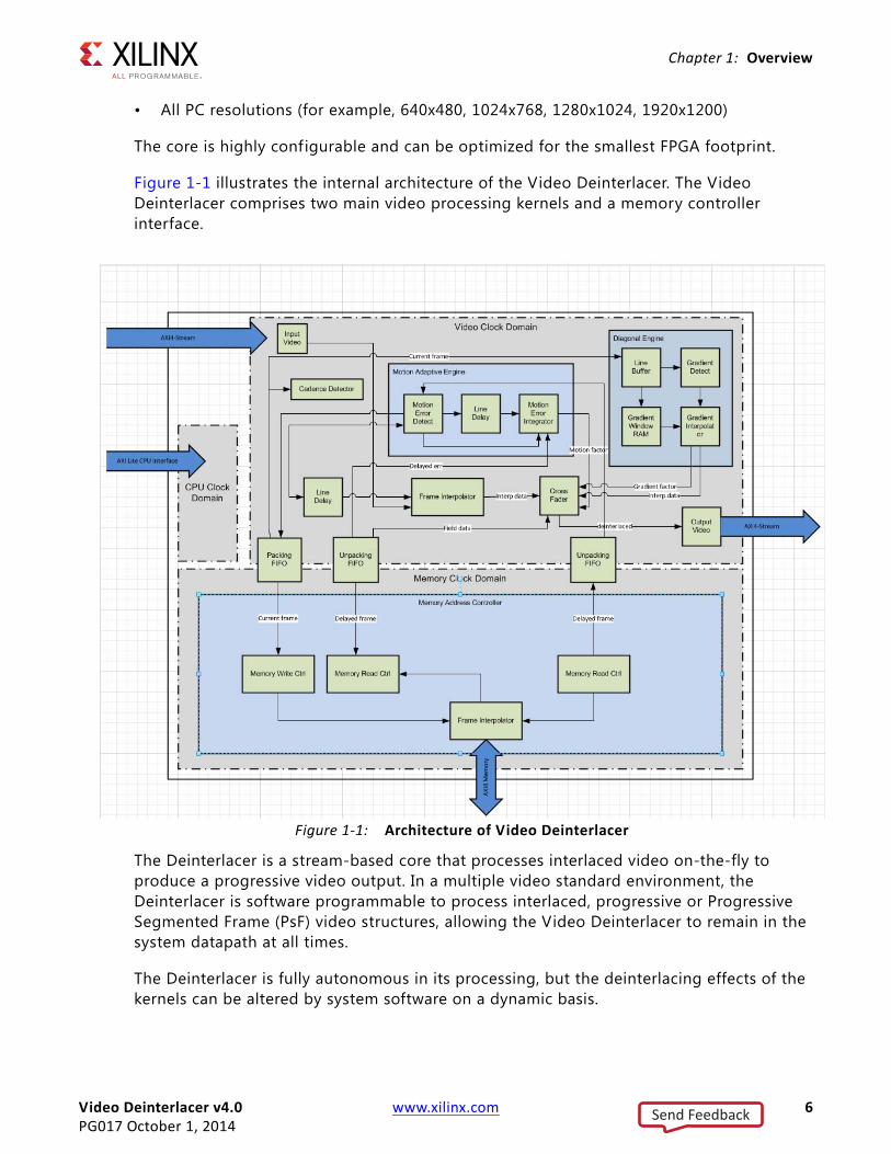
Figure 1-1 illustrates the internal architecture of the Video Deinterlacer. The Video Deinterlacer comprises two main video processing kernels and a memory controller interface.
The Deinterlacer is a stream-based core that processes interlaced video on-the-fly to produce a progressive video output. In a multiple video standard environment, the Deinterlacer is software programmable to process interlaced, progressive or Progressive Segmented Frame (PsF) video structures, allowing the Video Deinterlacer to remain in the system datapath at all times.
The Deinterlacer is fully autonomous in its processing, but the deinterlacing effects of the kernels can be altered by system software on a dynamic basis.
X-Ref Target - Figure 1-1
Figure 1-1: Architecture of Video Deinterlacer
Send Feedback

Video Deinterlacer v4.0 www.xilinx.com 7PG017 October 1, 2014
Chapter 1: Overview
The deinterlacing algorithm is based on a combination of motion adaptive concepts combined with diagonal interpolation techniques, resulting in a high quality deinterlaced image.
Figure 1-2 shows a traditional output from a motion adaptive deinterlacer. The staircase effect of fast moving video causes a f ield interpolation distortion effect on the output video.
Using the Deinterlacer core, a blend of motion and diagonal algorithms are combined to create the image in Figure 1-3. The Deinterlacer's algorithms recognize motion and detect diagonal vectors. These are combined to form a cleaner pixel that is used in the output video.
Feature SummaryApplications include:
• Conversion of interlaced SD to progressive SD
• Conversion of interlaced HD to progressive HD
• Conversion of CCD image data to a progressive image
X-Ref Target - Figure 1-2
Figure 1-2: Classic Motion Adaptive Deinterlacing Techniques
X-Ref Target - Figure 1-3
Figure 1-3: Xilinx Video Deinterlacer Deinterlacing Algorithm
Send Feedback

Video Deinterlacer v4.0 www.xilinx.com 8PG017 October 1, 2014
Chapter 1: Overview
• Reconstruction of original 24P f ilm rate from an interlaced source
• Combined with Xilinx Video Scaler, SD to HD up-conversion system
Licensing and Ordering InformationThis Xilinx LogiCORE IP module is provided under the terms of the Xilinx Core License Agreement. The module is shipped as part of the Vivado Design Suite. For full access to all core functionalities in simulation and in hardware, you must purchase a license for the core. Contact your local Xilinx sales representative for information about pricing and availability.
For more information, visit the Video Deinterlacer product web page.
Information about other Xilinx LogiCORE IP modules is available at the Xilinx Intellectual Property page. For information on pricing and availability of other Xilinx LogiCORE IP modules and tools, contact your local Xilinx sales representative.
Send Feedback

Video Deinterlacer v4.0 www.xilinx.com 9PG017 October 1, 2014
Chapter 2
Product Specification
StandardsThe Video Deinterlacer core is compliant with the AXI4-Stream Video Protocol and AXI4-Lite interconnect standards. Refer to the Video IP: AXI Feature Adoption section of the AXI Reference Guide (UG1037) [Ref 2] for additional information.
Performance
Deinterlacing Quality ConfigurationsThe Deinterlacer comprises these possible quality levels of deinterlacing:
• On-the-fly f ield interpolation (lowest quality)
• On-the-fly f ield interpolation with diagonal enhancement
• Motion adaptive
• Motion adaptive and diagonal enhancement (highest quality)
The Deinterlacer can either be statically configured at core generation time or dynamically configured via the AXI4-Lite interface to perform any of the previous deinterlacing techniques on input video.
Inclusion of the motion adaptive (C_MOTION=1) core requires an AXI-MM based external memory interface. The external interface is used to provide the highest possible quality of deinterlacing. Opting out of the motion adaption core (C_MOTION=0) removes the need for an external memory interface and significantly reduces the FPGA resources required. However, the trade-off is lower quality of the output image. The AXI-MM interface ports are not used in this configuration.
Inclusion of the diagonal (C_DIAG=1) core requires only standard FPGA resources (DSP and block RAM) with the benefit of increased image quality.
Send Feedback

Video Deinterlacer v4.0 www.xilinx.com 10PG017 October 1, 2014
Chapter 2: Product Specification
LatencyLatency equals the average approximate 3 video lines from first pixel entering the core to f irst pixel coming out of video output port.
ThroughputThe Deinterlacer creates 2 pixels for every input pixel. Due to this, the Deinterlacer requires that the video clock be at minimum twice the video input pixel rate, to allow the internal processing enough clock cycles to generate the output pixels.
There is a 1 line push back buffer at the input of the Deinterlacer, to allow for a small amount of sporadic pixel loading into the Deinterlacer. But systems that may exhibit more fluctations on input data loading should consider external line buffer blocks that are beyond the scope of the Deinterlacer.
There is a 1000 pixel output push back buffer, to allow for small fluctations in the ability for a downstream component to accept data.
If either the input or output buffers overflow, the Deinterlacer will raise an interrupt and automatically flush the video pipe and attempt to resynchronize with the passing video on the next frame boundary. All input video will be dropped during this resynchronization phase.
Resource UtilizationThe maximum achievable clock can vary and can depend on the size of the device, various aspects of the system design, and other variables.
Resources required for 7-series and Zynq-7000 devices are shown in the following tables.
The following estimates show the range of resources for a given feature set, which span 8, 10 and 12-bit video data path options per row.
Table 2-1: Kintex-7 and Zynq-7000 Devices with Kintex Based Programmable Logic
Feature Quality Memory Interface Slice FFs Slice LUTs LUT-FF
Pairs DSP48 Clock Freq (Mhz)
Basic Field Interpolation
Low none 1016 ~ 1151
1033 ~ 1183
1184 ~ 1349
6 304 ~ 320
Basic Field Interpolation with
Diagonal Enhancement
Average none 2033 ~ 2447
1889 ~ 2317
2100 ~ 2485
19 304 ~ 328
Send Feedback

Video Deinterlacer v4.0 www.xilinx.com 11PG017 October 1, 2014
Chapter 2: Product Specification
Motion based, no Diagonal, 32-bit
AXI-MM
High AXI - 32 bit 3022 ~ 3212
2496 ~ 2580
3107 ~ 3203
7 304 ~ 320
Full Motion & Diagonal, 32-bit
AXI-MM
Highest AXI - 32 bit 4023 ~ 4455
3389 ~ 3653
3907 ~ 4331
20 312 ~ 328
Typical High Quality Configuration
(10bit, 444, 32-bit AXI + Motion +
Diagonal + Cadence)
Highest AXI - 32 bit 4659 ~ 5127
3888 ~ 4195
4534 ~ 5020
21 304 ~ 320
Incremental Resource Changes Based on previous row (with Cadence)
Increase AXI to 64-bit instead of
32-bit
Highest AXI - 64 bit 4730 ~ 5182
3931 ~ 4232
4682 ~ 4990
21 304 ~ 320
Increase AXI to 128-bit instead of
32-bit
Highest AXI - 128 bit
4865 ~ 5317
3993 ~ 4290
4942 ~ 5276
21 296 ~ 328
Increase AXI to 256-bit instead of
32-bit
Highest AXI - 256 bit
5144 ~ 5580
4054 ~ 4336
5200 ~ 5530
21 312 ~ 328
Table 2-1: Kintex-7 and Zynq-7000 Devices with Kintex Based Programmable Logic (Cont’d)
Feature Quality Memory Interface Slice FFs Slice LUTs LUT-FF
Pairs DSP48 Clock Freq (Mhz)
Table 2-2: Artix-7 and Zynq-7000 Devices with Artix Based Programmable Logic
Feature Quality Memory Interface Slice FFs Slice LUTs LUT-FF
pairs DSP48 Clock Freq (Mhz)
Basic Field Interpolation
Low none 1032 ~ 1151
1044 ~ 1183
1154 ~ 1318
6 242 ~ 258
Basic Field Interpolation with
Diagonal Enhancement
Average none 2033 ~ 2447
1892 ~ 2321
2123 ~ 2499
19 219 ~ 242
Motion based, no Diagonal, 32-bit
AXI-MM
High AXI - 32 bit 3022 ~ 3212
2520 ~ 2608
3093 ~ 3173
7 250
Full Motion & Diagonal, 32-bit
AXI-MM
Highest AXI - 32 bit 4009 ~ 4471
3351 ~ 3682
3985 ~ 4321
20 226 ~ 234
Typical High Quality Configuration
(10bit, 444, 32-bit AXI + Motion +
Diagonal + Cadence)
Highest AXI - 32 bit 4659 ~ 5127
3903 ~ 4217
4726 ~ 5044
21 226 ~ 234
Incremental Resource Changes Based on previous row (with Cadence)
Send Feedback

Video Deinterlacer v4.0 www.xilinx.com 12PG017 October 1, 2014
Chapter 2: Product Specification
Increase AXI to 64-bit instead of
32-bit
Highest AXI - 64 bit 4746 ~ 5198
3968 ~ 4266
4639 ~ 5084
21 226 ~ 234
Increase AXI to 128-bit instead of
32-bit
Highest AXI - 128 bit
4865 ~ 5317
3993 ~ 4290
4942 ~ 5276
21 219 ~ 234
Increase AXI to 256-bit instead of
32-bit
Highest AXI - 256 bit
5128 ~ 5580
4065 ~ 4358
5360 ~ 5612
21 226 ~ 234
Table 2-2: Artix-7 and Zynq-7000 Devices with Artix Based Programmable Logic (Cont’d)
Feature Quality Memory Interface Slice FFs Slice LUTs LUT-FF
pairs DSP48 Clock Freq (Mhz)
Table 2-3: Virtex-7 and Zynq-7000 Devices with Virtex Based Programmable Logic
Feature Quality Memory Interface Slice FFs Slice LUTs LUT-FF
pairs DSP48 Clock Freq (Mhz)
Basic Field Interpolation
Low none 1032 ~ 1167
1045 ~ 1196
1192 ~ 1364
6 304 ~ 344
Basic Field Interpolation with
Diagonal Enhancement
Average none 2033 ~ 2447
1890 ~ 2318
2132 ~ 2545
19 312
Motion based, no Diagonal, 32-bit
AXI-MM
High AXI - 32 bit 3006 ~ 3228
2486 ~ 2593
3147 ~ 3200
7 312 ~ 336
Full Motion & Diagonal, 32-bit
AXI-MM
Highest AXI - 32 bit 4009 ~ 4471
3330 ~ 3667
4067 ~ 4338
20 304
Typical High Quality Configuration
(10bit, 444, 32-bit AXI + Motion +
Diagonal + Cadence)
Highest AXI - 32 bit 4675 ~ 5111
3902 ~ 4186
4652 ~ 5012
21 304 ~ 312
Incremental Resource Changes Based on previous row (with Cadence)
Increase AXI too64-bit instead of
32-bit
Highest AXI - 64 bit 4730 ~ 5182
3934 ~ 4236
4738 ~ 5133
21 304 ~ 312
Increase AXI too128-bit instead
of 32-bit
Highest AXI - 128 bit
4865 ~ 5317
3987 ~ 4265
4944 ~ 5237
21 312 ~ 320
Increase AXI too256-bit instead
of 32-bit
Highest AXI - 256 bit
5144 ~ 5580
4056 ~ 4344
5343 ~ 5608
21 296 ~ 312
Send Feedback

Video Deinterlacer v4.0 www.xilinx.com 13PG017 October 1, 2014
Chapter 2: Product Specification
Core Interfaces This chapter provides detailed descriptions for each interface. In addition, detailed information about configuration and control registers is included.
Port Descriptions
Core Interfaces
Memory Mapped Interface
When configured to support motion based deinterlacing, the Video Deinterlacer requires an external memory port to perform this operation. The core can be configured to support a single bi-directional AXI4-Memory Mapped interface.
The core provides registers to allow you to specify the location in external memory of the data-buffers that are used by the motion tracking algorithm.
Processor Interface
An AXI4-Lite interface is made available for use by a system CPU or other AXI master. The processor interfaces gives full access to the Deinterlacer's internal registers and interrupt systems. The internal status of the Deinterlacer can also be monitored through this interface
Video Streaming Input Interface
The core has a single video input port with AXI4-Streaming Protocol.
Video Streaming Output interface
The core has a single video output port with AXI4-Streaming Protocol.
Common I/O Signals
The interface share some common global signals. These are:
The cores video interface pins are shown below:
Table 2-4: Common Interfaces Signals
Port Name Dir Width Description
aclk I 1 Main system video clock. Synchronous to AXI4-Streaming in and out ports
aresetn I 1 Synchronous system reset.
aclken I 1 Main system video clock enable. Used to throttle data passing through the Deinterlacer.
Send Feedback

Video Deinterlacer v4.0 www.xilinx.com 14PG017 October 1, 2014
Chapter 2: Product Specification
External Memory Interface Signals
When configured with an AXI-MM interface the following signals are present:
Table 2-5: AXI4-Stream Data Signal Descriptions
Port Name Dir Width Description
m_axis_video_tdata O 16, 24, 32, 40 Output Video Data
m_axis_video_tstrb O [m_axis_video_tdata/8-1:0] Output Video Data Strobe
m_axis_video_tvalid O 1 Output Valid
m_axis_video_tready I 1 Output Valid
m_axis_video_tlast O 1 Output Video End Of Line
m_axis_video_tuser O 1 Output Video Start Of Frame
s_axis_tdata I 16, 24, 32, 40 Input Video Data
s_axis_tstrb I [s_axis_tdata/8-1:0] Input Video Data Strobe
s_axis_tvalid I 1 Input Valid
s_axis_tready O 1 Input Ready
s_axis_tlast I 1 Input Video End Of Line
s_axis_tuser I 1 Input Video End Of Line
Table 2-6: AXI-MM Interface Signals
Port Name Dir Width Description
AXI4-Lite Slave Interface
m_axi_aclk I 1 AXI master clock. The AXI MM port is synchronous to this clock
m_axi_awaddr O [31:0] AXI Write Address
m_axi_awid O [C_M_AXI_THREAD_ID_WIDTH-1] AXI Write Thread ID
m_axi_awlen O [7:0] AXI Write Burst Length
m_axi_awsize O [2:0] AXI Write Beat Size
m_axi_awburst O [1:0] AXI Write Burst Type
m_axi_awlock O 1 AXI Write Transaction lock
m_axi_awcache O [3:0] AXI Write Cache Type
m_axi_awprot O [2:0] AXI Write Protection Level
m_axi_awqos O [3:0] AXI Write Quality of Service
m_axi_awvalid O 1 AXI Write Address Valid
m_axi_awready I 1 AXI Write Address acknowledge
m_axi_wdata O [C_M_AXI_DATA_WIDTH-1:0] AXI Write Data
m_axi_wstrb O [C_M_AXI_DATA_WIDTH/8-1:0] AXI Write Data Strobes
m_ax_wlast O 1 AXI Write Burst Last Beat
Send Feedback

Video Deinterlacer v4.0 www.xilinx.com 15PG017 October 1, 2014
Chapter 2: Product Specification
When configured with an AXI4-Lite interface the following signals are present:
m_axi_wvalid O 1 AXI Write Data Valid
m_axi_wready I 1 AXI Write Data acknowledge
m_axi_bid I [C_M_AXI_THREAD_ID_WIDTH-1:0] AXI Write Response Thread ID
m_axi_bresp I 2 AXI Write Response
m_axi_bvalid I 1 AXI Write Response Valid
m_axi_bready O 1 AXI Write Response Acknowledge
m_axi_arid O [C_M_AXI_THREAD_ID_WIDTH-1:0] AXI Read Thread ID
m_axi_araddr O [31:0] AXI Read Address
m_axi_arlen O [7:0] AXI Read Burst Length
m_axi_arsize O [2:0] AXI Read Burst beat size
m_axi_arburst O [1:0] AXI Read Burst type
m_axi_arlock O 1 AXI Read Transaction Locked
m_axi_arcache O [3:0] AXI Read Transaction Protection Level
m_axi_arprot O [2:0] AXI Read Cache type
m_axi_arqos O [3:0] AXI Read Quality of Service
m_axi_arvalid O 1 AXI Read Address Valid
m_axi_arready I 1 AXI Read Address acknowledge
m_axi_rid I [C_M_AXI_THREAD_ID_WIDTH-1:0] AXI Read Data Thread ID
m_axi_rdata I [C_M_AXI_DATA_WIDTH-1:0] AXI Read Data
m_axi_rresp I 2 AXI Read Response
m_axi_rlast I 1 AXI Read Data Burst Last beat strobe.
m_axi_rvalid I 1 AXI Read Response Valid
m_axi_rready O 1 AXI Reset Response acknowledge
Table 2-6: AXI-MM Interface Signals (Cont’d)
Port Name Dir Width Description
Table 2-7: AXI4-Lite Interfaces
Port Name Dir Width Description
AXI4-Lite Slave Interface
s_axi_aclk I 1 CPU clock. The AXI slave interface is synchronous to this clock
s_axi_awaddr I [31:0] AXI Write Address
s_axi_awvalid I 1 AXI Write Address Valid
s_axi_awready O 1 AXI Write Address acknowledge
s_axi_wdata I [31:0] AXI Write Data
s_axi_wvalid I 1 AXI Write Data Valid
Send Feedback

Video Deinterlacer v4.0 www.xilinx.com 16PG017 October 1, 2014
Chapter 2: Product Specification
Data InterfaceThe Video Deinterlacer core receives and transmits data using AXI-Stream interfaces that implement a video protocol as defined in the AXI Reference Guide (UG1037), Video IP: AXI Feature Adoption section.
AXI4-Stream Signal Name and Description
Table 2-5 describes the AXI4-Stream signal names and descriptions.
Video Data
The AXI4-Stream interface specif ication restricts TDATA widths to integer multiples of 8 bits. The Video Deinterlacer supports 4:2:2 YC and 4:4:4/RGB video streams for 8, 10 and 12 bit video data.
The active video data always observes the following principles on an AXI4-Stream TDATA port:
For the 4:2:2 YC case,
• Y always occupies bits (Video_Data_Width-1:0)
• C always occupies bits ((2*Video_Data_Width)-1: Video_Data_Width)
An example showing 10-bit YC data is shown in Figure 2-1.
s_axi_wready O 1 AXI Write Data acknowledge
s_axi_bresp O 2 AXI Write Response
s_axi_bvalid O 1 AXI Write Response Valid
s_axi_bready I 1 AXI Write Response Acknowledge
s_axi_araddr I [31:0] AXI Read Address
s_axi_arvalid I 1 AXI Read Address Valid
s_axi_arready O 1 AXI Read Address acknowledge
s_axi_rdata O [31:0] AXI Read Data
s_axi_rresp O 2 AXI Read Response
s_axi_rvalid O 1 AXI Read Response Valid
s_axi_rready I 1 AXI Reset Response acknowledge
irq O 1 CPU interrupt request. Active High Level interrupt synchronous to s_axi_aclk
Table 2-7: AXI4-Lite Interfaces
Port Name Dir Width Description
Send Feedback

Video Deinterlacer v4.0 www.xilinx.com 17PG017 October 1, 2014
Chapter 2: Product Specification
For the RGB case,
° G occupies bits (Video_Data_Width-1:0)
° B occupies bits ((2*Video_Data_Width)-1: Video_Data_Width)
° R occupies bits ((3*Video_Data_Width)-1: (2*Video_Data_Width))
In all cases, the MSB of each component is the uppermost bit in the above scheme. 0-padding should be used for unused AXI4-Stream bits.
Figure 2-2 shows 12-bit RGB data.
READY/VALID HandshakeA valid transfer occurs whenever READY, VALID, and ARESETn are high at the rising edge of ACLK, as seen in Figure 2-3. During valid transfers, DATA only carries active video data. Blank periods and ancillary data packets are not transferred via the AXI4-Stream video protocol.
Guidelines on Driving TVALID into Slave (Data Input) Interfaces.When tvalid is asserted, no interface signals (except the Video Deinterlacer core driving tready) can change value until the transaction completes (tready, tvalid High on the rising edge of ACLK). When asserted, tvalid can only be deasserted after a transaction has completed. Transactions can not be retracted or aborted. In any cycle following a transaction, tvalid can either be deasserted or remain asserted to initiate a new transfer.
X-Ref Target - Figure 2-1
Figure 2-1: YUV Data Embedding on TDATA
X-Ref Target - Figure 2-2
Figure 2-2: RGB Data Embedding on TDATA
816243240
Component GComponent BComponent R
bit 0
0 pad
Send Feedback

Video Deinterlacer v4.0 www.xilinx.com 18PG017 October 1, 2014
Chapter 2: Product Specification
Deinterlacer uses tstrb when High to indicate a byte of data that contains valid information and must be transmitted between source and destination.
.
Guidelines on Driving TREADY into Master (Data Output) InterfacesThe tready signal can be asserted before, during, or after the cycle in which the Video Deinterlacer core asserted tvalid. The assertion of tready can be dependent on the value of tvalid. A slave that can immediately accept data qualif ied by tvalid, should preassert its tready signal until data is received. Alternatively, tready can be registered and driven the cycle following tvalid assertion.
RECOMMENDED: It is recommended that the AXI4-Stream slave should drive TREADY independently, or preassert TREADY to minimize latency.
Start of Frame Signals - m_axis_video_tuser, s_axis_video_tuserThe Start-Of-Frame (SOF) signal, physically transmitted over the AXI4-Stream TUSER signal, marks the first pixel of f irst incoming video field at slave/input side and f irst pixel of every outgoing video frame at the master/output side. Every incoming interlaced Video Frame represented by two video fields, which are odd line and even line video f ield. The SOF pulse is 1 valid transaction wide, and must coincide with the f irst pixel of the frame. Refer to Figure 2-4.
SOF serves as a frame synchronization signal, which allows downstream cores to reinitialize, and detect the first pixel of a frame/first f ield. The SOF signal can be asserted an arbitrary number of ACLK cycles before the first pixel value is presented on TDATA, as long as a TVALID is not asserted.
X-Ref Target - Figure 2-3
Figure 2-3: Example of TREADY/TVALID Handshake
Send Feedback

Video Deinterlacer v4.0 www.xilinx.com 19PG017 October 1, 2014
Chapter 2: Product Specification
End of Line Signals - m_axis_video_tlast, s_axis_video_tlastThe End-Of-Line signal, physically transmitted over the AXI4-Stream TLAST signal, marks the last pixel of a line. The EOL pulse is 1 valid transaction wide, and must coincide with the last pixel of a scan-line, as seen in Figure 2-5.
Register SpaceThis section provides the programming interface register information.
All registers power up with 0x0. Only the control, mode and interrupt control registers are reset to 0x0 during a software reset, all other registers retain their current settings.
X-Ref Target - Figure 2-4
Figure 2-4: Example of SOF Handshake, Start of a New Frame
X-Ref Target - Figure 2-5
Figure 2-5: Use of EOL
Table 2-8: Register Name and Descriptions
Address (hex) BASEADDR + Register Name Access
Type Default Value Register Description
0x0000 Control R/W 0x0 Bit 0: Update RequestBit 1: Deinterlacer Enable (Bypass/Passthru)Bit 2: Deinterlacer Accept Video
Send Feedback

Video Deinterlacer v4.0 www.xilinx.com 20PG017 October 1, 2014
Chapter 2: Product Specification
0x0004 Mode R/W 0x0 Bit 0-1: Deinterlacing AlgorithmBit 2: Color SpaceBit 3-4: Packing FormatBit 5: Field OrderBit 6: PsF EnableBit 7: Pull-down Enable 3:2Bit 8: Pull-down Enable 2:2Bit 9: Pull-down 2:2 Field PrecedenceBit 16: Colorize MotionBit 17: Colorize Diagonal
0x0008 Interrupt Control R/W 0x0 Bit 0: Update InterruptBit 1: Synch onBit 2: Synch offBit 3: Deinterlacer ErrorBit 4: Pull-down onBit 5: Pull-down offBit 6: Frame InterruptBit 8: Framestore Wr MarkerBit 9: Framestore Wr ErrBit 10: Framestore Rd Err 0Bit 11: Framestore Rd Err 1
0x000C Interrupt Status R/W 0x0 Bit 0: Update Interrupt Bit 1: Synch onBit 2: Synch offBit 3: Deinterlacer ErrorBit 4: Pull-down onBit 5: Pull-down offBit 6: Frame InterruptBit 8: Framestore Wr MarkerBit 9: Framestore Wr ErrBit 10: Framestore Rd Err 0bit 11: Framestore Rd Err 1
0x0010 Height R/W 0x0 Bit 0-10: Height
0x0014 Width R/W 0x0 Bit 0-10: Width
0x0018 Threshold T1 R/W 0x0 Bit 0-9: T1 setting
0x001C Threshold T2 R/W 0x0 Bit 0-9: T2 setting
0x0020 Cross Fade Scale R/W 0x0 Bit 0-15: Cross Fade Scale
0x0024 Buffer 0 Base R/W 0x0 Bit 0-31: Buffer 0 Base
0x0028 Buffer 1 Base R/W 0x0 Bit 0-31: Buffer 1 Base
0x002C Buffer 2 Base R/W 0x0 Bit 0-31: Buffer 2 Base
0x0030 Buffer Size R/W 0x0 Bit 0-23: Triple buffer segment size
Table 2-8: Register Name and Descriptions
Send Feedback

Video Deinterlacer v4.0 www.xilinx.com 21PG017 October 1, 2014
Chapter 2: Product Specification
0x0004 Mode R/W 0x0 Bit 0-1: Deinterlacing AlgorithmBit 2: Color SpaceBit 3-4: Packing FormatBit 5: Field OrderBit 6: PsF EnableBit 7: Pull-down Enable 3:2Bit 8: Pull-down Enable 2:2Bit 9: Pull-down 2:2 Field PrecedenceBit 16: Colorize MotionBit 17: Colorize Diagonal
0x0008 Interrupt Control R/W 0x0 Bit 0: Update InterruptBit 1: Synch onBit 2: Synch offBit 3: Deinterlacer ErrorBit 4: Pull-down onBit 5: Pull-down offBit 6: Frame InterruptBit 8: Framestore Wr MarkerBit 9: Framestore Wr ErrBit 10: Framestore Rd Err 0Bit 11: Framestore Rd Err 1
0x000C Interrupt Status R/W 0x0 Bit 0: Update Interrupt Bit 1: Synch onBit 2: Synch offBit 3: Deinterlacer ErrorBit 4: Pull-down onBit 5: Pull-down offBit 6: Frame InterruptBit 8: Framestore Wr MarkerBit 9: Framestore Wr ErrBit 10: Framestore Rd Err 0bit 11: Framestore Rd Err 1
0x0010 Height R/W 0x0 Bit 0-10: Height
0x0014 Width R/W 0x0 Bit 0-10: Width
0x0018 Threshold T1 R/W 0x0 Bit 0-9: T1 setting
0x001C Threshold T2 R/W 0x0 Bit 0-9: T2 setting
0x0020 Cross Fade Scale R/W 0x0 Bit 0-15: Cross Fade Scale
0x0024 Buffer 0 Base R/W 0x0 Bit 0-31: Buffer 0 Base
0x0028 Buffer 1 Base R/W 0x0 Bit 0-31: Buffer 1 Base
0x002C Buffer 2 Base R/W 0x0 Bit 0-31: Buffer 2 Base
0x0030 Buffer Size R/W 0x0 Bit 0-23: Triple buffer segment size
Table 2-8: Register Name and Descriptions
Send Feedback

Video Deinterlacer v4.0 www.xilinx.com 22PG017 October 1, 2014
Chapter 2: Product Specification
Control (0x0000) Register
Bit 0 of the control register, Update Register, setting this bit to '1' arms the Deinterlacer to perform a register shadow update on the next frame boundary. Setting this bit to ‘0’ cancels any pending shadow request.
Bit 1 of the control register, Deinterlacer Enable, while the Deinterlacer is disabled, active video passes through the Deinterlacer in its original form. Allowing the Video Deinterlacer to operate in Bypass or Passthru mode, all Blanking information is always stripped by the Deinterlacer.
Bit 2 of the control register, Deinterlacer Accept Video, instructs the video on whether to accept or ignore all video at the input to the Deinterlacer. This bit takes affect on the subsequent input video frame boundary.
Mode (0x0004) Register
Bit 1:0 of the Mode register, Deinterlacing Algorithm, is used to set the deinterlacing method. When set to 0, pure f ield interpolating techniques are used. When set to 1, only the diagonal engine is used. When set to 2, only motion adaptive engine is used. When set to 3, both motion and diagonal engines are used.
Bit 2 of the Mode register, Color Space, is used to set the color space of video. When set to ‘0’ YUV color space is used. When set to ‘1’ RGB color space is used.
Bit 4:3 of the Mode register, Packing Format, is used to set the packing formats used on the input and output. When set to 0, 4:2:0 packing is used. When set to 1, 4:2:2 packing is used. When set to 2, 4:4:4 packing is used. See the Video Interface, page 37 for more information.
Bit 5 of the Mode register, Field Order, is used to set the first f ield order of input video. When set 1, the f ield order maps to NTSC/480i. When set 0 the f ield order maps to PAL/HD/3G.
Bit 6 of the Mode register, PsF Enable, is used to enable the Progressive Segmented Frame Enable which controls if the Deinterlacer is processing interlaced, PSF, or progressive image structures. You must enable the motion adaptive when enabling PsF mode.
Bit 7 of Mode register, Pull-down Enable 3:2, allows detectors to automatically control Deinterlacer.
0x00F0 Version ID R 0x04000000 Bit 16-19: Revision LetterBit 20-23: Minor VersionBit 24-31: Major Version
0x0100 Soft Reset R/W 0x0 Bit 0: Soft Reset
Table 2-8: Register Name and Descriptions
Send Feedback

Video Deinterlacer v4.0 www.xilinx.com 23PG017 October 1, 2014
Chapter 2: Product Specification
Bit 8 of Mode register, Pull-down Enable 2:2, allows detectors to automatically control Deinterlacer.
Bit 9 of Mode register, Pull-down 2:2 Field Precedence, allows the phase to be flipped inside the Deinterlacer so inverted sequence encoding (for example, dodgy MPEG2) can be used. When set to 0, normal mode is used and no flipping/swapping is done. When set to 1, Deinterlacer swaps the phase of the interlaced video internally.
Bit 16 of Mode register, Colorize Motion enable colorizing output image with motion algorithm output.
Bit 17 of Mode register, Colorize Diagonal enable colorizing output image with diagonal algorithm output.
Interrupt Control (0x0008) Register
Bit 0 of the Interrupt Control register, Update Interrupt, enables the register shadow update done interrupt when set to 1.
Bit 1 of the Interrupt Control register, Sync on, enables lock of input video detector.
Bit 2 of the Interrupt Control register, Sync off, enables loss of video lock detector.
Bit 3 of the Interrupt Control register, Deinterlacer Error, enables internal diagnostic error interrupt.
Bit 4 of the Interrupt Control register, Pull-down on, enables pull-down activation detection.
Bit 5 of the Interrupt Control register, Pull-down off, enables pull-down loss detection.
Bit 6 of the Interrupt Control Register, Frame Interrupt, enables the video frame border interrupt when set to 1, which indicates when a frame boundary has been passed.
Bit 8 of the Interrupt Control Register, Frame Wr Marker, enables Framestore integrity checking.
Bit 9 of Interrupt Control Register, Framestore Wr Err, enable Framestore integrity check on AXI-MM port for FIFO over run.
Bit 10-11 of Interrupt Control Register, Framestore Rd Err 1/0, enable Framestore integrity check on AXI-MM port for FIFO under run.
Interrupt Status (0x000C) Register
Bit 0 of the Interrupt Status register, Update Interrupt, when set to '1' indicates an internal register update has occurred.
Bit 2:1 of the Interrupt Status register, Synch on/off, when set indicate Deinterlacer is in-sync/lost-sync to input video respectively.
Send Feedback

Video Deinterlacer v4.0 www.xilinx.com 24PG017 October 1, 2014
Chapter 2: Product Specification
Deinterlacer synchronization: Indicates input video raster is stable and matches programmed x/y sizes known to Deinterlacer.
Deinterlcaer has lost synchronization: Indicates different input video raster does not match the programmed x/y sizes known to the Deinterlacer, or that the input video is not stable.
Bit 3 of the Interrupt Status register, Deinterlacer Error, when set to '1' indicates internal FIFO overrun error. This occurs if the AXI-Stream clock is not fast enough to process the input video.
Bit 4 of the Interrupt Status register, Pull-down on, when set to '1' indicates pull-down detector has found a pull down sequence and the output video is derived by the cadence.
Bit 5 of the Interrupt Status register, Pull-down off, when set to '1' indicates pull-down detector has seen pull down sequence cadence disappeared and the Deinterlacer is reverting to normal mode.
Bit 6 of the Interrupt Status register, Frame Interrupt, when set to '1' indicates a video frame boundary has passed.
Bit 8 of the Interrupt Status register, Framestore Wr Marker, when set to '1' indicates framestore experiencing video data frames that do not match the programmed settings.
Bit 9 of the Interrupt Status register, Framestore Wr Err, when set to '1' indicates the AXI-MM port is experiencing FIFO overrun.
Bit 10-11 of the Interrupt Status register, Framestore Rd Err 1/0, when set indicates the AXI-MM port is experiencing FIFO under run.
Height (0x0010) Register
Bits 10:0 of the Height register, Height, is to set the input pixel height of video frame. The frame height should be set to the value of the deinterlaced video. The line count stats at 1 and only even fame sizes are supported. For example, for a 1080i input, the Height should be set to 1080 = 0x438.
Width (0x0014) Register
Bits 10:0 of the Width register, Width, is to set the input pixel width of video frame. The frame width should be set to the value of the deinterlaced video. The line count stats at 1. When the motion engine is enabled, for 8 or 10-bit images, the width must be divisible by 4, and for 12-bit images, the width must be divisible by 2. For example, for a 1080i input the height should be set to 1920 = 0x7801920/4 = 4801920/2 = 960
Send Feedback

Video Deinterlacer v4.0 www.xilinx.com 25PG017 October 1, 2014
Chapter 2: Product Specification
Threshold T1 (0x0018) Register
Bits 9:0 of the Threshold T1 register, T1 setting, is to set the low motion adaptive T1 threshold value. See T1 and T2, page 28 and Cross Fade Ratio, page 29 for more information.
Threshold T2 (0x001C) Register
Bit 9:0 of the Threshold T2 register. T2 setting, is to set high motion adaptive T2 threshold value. See T1 and T2, page 28 and Cross Fade Ratio, page 29 for more information.
Cross Fade Scale (0x0020) Register
Bit f ield of this register (0 to 15 bit) is used for Motion Adaptive cross fade scaling factor and must be programmed with the equation = (4096*256)/(register T2- register T1). See T1 and T2, page 28 and Cross Fade Ratio, page 29 for more information.
Buffer 0 (0x0024) Register
Bit f ield of this register is used to set base address in external memory of the f irst f ield buffer.
Buffer 1 (0x0028) Register
Bit f ield of this register is used to set base address in external memory of the second f ield buffer.
Buffer 2 (0x002C) Register
Bit f ield of this register is used to set base address in external memory of the third f ield buffer.
Buffer Size (0x0030) Register
Bit f ield of this register (0 to 23 bit) is used to set the framestore buffer size (in 32-bit words). See Memory Size, page 31 for more information.
Version ID (0x00F0) Register
Bit f ields of the Version Register facilitate software identif ication of the exact version of the hardware peripheral incorporated into a system. The core driver can take advantage of this Read-Only value to verify that the software is matched to the correct version of the hardware. See Table 2-8 for details.
Send Feedback
Video Deinterlacer v4.0 www.xilinx.com 26PG017 October 1, 2014
Chapter 2: Product Specification
Soft Reset (0x0100) Register
A single bit that is used to initiate a soft reset when set to 1. This resets the internal Deinterlacer to its default state and purges all video within the Deinterlacer. This bit clears itself to zero after the soft reset has completed.
Send Feedback

Video Deinterlacer v4.0 www.xilinx.com 27PG017 October 1, 2014
Chapter 3
Designing with the CoreThis chapter includes guidelines and additional information to make designing with the core easier.
ArchitectureThe Xilinx Video Deinterlacer converts a live input video stream into a progressive video structure. Figure 1-1 illustrates a high-level view of the ports of the Deinterlacer.
In conjunction with the video path, the AXI4-MM ports read and write passing video f ields to and from a memory buffer. These f ields of information are used by the Deinterlacer internal processing blocks to produce the f inal progressive video output.
In creating progressive pictures, the output frame rate of the Deinterlacer is always twice the input rate and produces one pixel per clock. The video clock used must meet this system requirement. The input pixel rate must be less than or equal to the video clock rate divided by two. The output pixel rate is always twice the input pixel rate. A single common video clock is used for the entire video path.
The Video Deinterlacer input can be either from live video or a stored video feed. The AXI4-Stream input bus allows for continuous or burst input rates. An optional full flag allows for push back of input data when the Deinterlacer is receiving input from a non-live video feed. The AXI4-Stream output bus produces output pixels whenever there is a pixel inside the Deinterlacer to be generated. The Video Deinterlacer has only minimal buffering inside. It is important to not overflow the input FIFO.
DeinterlacingThe Deinterlacer contains two processing kernels: the motion adaptive and the diagonal detection and adaptation processing kernels. These kernels work together to form each deinterlaced pixel.
The motion adaptive kernel has two threshold parameters that can be adjusted by the user if required. These two parameters are T1 and T2. They are used as threshold points for measuring between no motion, average motion, and excessive motion. In each of these
Send Feedback

Video Deinterlacer v4.0 www.xilinx.com 28PG017 October 1, 2014
Chapter 3: Designing with the Core
categories, the Deinterlacer generates the output pixels using different techniques. Figure 3-1 shows the conceptual relationship of the T1 and T2 parameters to the Deinterlacer pixel creator.
T1 and T2T1 and T2 can be set to these default values:
• Typical SDI YUV defaults: T1 = 10, T2 = 70
• Typical SDI RGB defaults: T1 = 100, T2 = 200
Generally, they should not be altered, but users can alter them depending on the noise level of the input video signal. If the input video source is noisy, this may be detected as
X-Ref Target - Figure 3-1
Figure 3-1: Output Pixel Decision Criteria
Send Feedback

Video Deinterlacer v4.0 www.xilinx.com 29PG017 October 1, 2014
Chapter 3: Designing with the Core
excessive motion and the output image may be of lower quality. In this case, the motion detection threshold can be increased by the application software.
Cross Fade RatioThe cross fade scale register is derived directly from T1 and T2 according to this f ixed equation:
xfade ratio = (4096*256)/(T2-T1)
This value is used internally to control cross fading between kernel pixels and the frame store pixels. This register must be changed whenever T1 or T2 are altered to ensure the correct operation of the cross fader.
Initial StateWhen the motion engine is enabled, the Deinterlacer kernel must have two f ields of video history to produce its desired output. During a video input standard change, start-up condition, change of format or error state, there is no video history for the Deinterlacer to use. For these frames (if enabled via software), the Deinterlacer produces progressive video outputs without the aid of the motion adaptive kernel. As a result, these initial frames appear softer in format until the memory interface has obtained suff icient history for producing the required output quality.
Figure 3-2 illustrates the sequencing of the Deinterlacer output with respect to input variance. The diagram shows the two initial frames (1 and 2) being created from raw passing video and then the remainder being produced with the aid of the historical data.
The second image shows a normally operating Deinterlacer that is suddenly subjected to a change in input video. The Deinterlacer then resets the memory interface and reverts to a lower quality, while it builds up new picture history over the f irst two frames. It then reverts to fully operational state.
Send Feedback

Video Deinterlacer v4.0 www.xilinx.com 30PG017 October 1, 2014
Chapter 3: Designing with the Core
Memory ControllerWhen the motion engine is enabled, the deinterlacing process requires two previous fields of video information to determine the amount of per-pixel motion present in the passing video. It then selects the most appropriate method of deinterlacing each pixel using these streams.
An external memory store is used in a triple buffer concept to store and extract passing video f ields and associating sideband data. At the end of each output frame, the memory controller moves its base pointers to the next buffer and starts again. Figure 3-3 illustrates the triple buffer movement.
X-Ref Target - Figure 3-2
Figure 3-2: Examples of Deinterlacer Start-up Conditions
Send Feedback

Video Deinterlacer v4.0 www.xilinx.com 31PG017 October 1, 2014
Chapter 3: Designing with the Core
The memory ports operate in a unidirectional manner, 1 write and 2 read. It continuously stores the incoming f ield with its motion vector and extracts f ields n-1 and f ield n-2 from the other two buffers. For more information on AXI-MM streams, refer to AXI4 Memory and Interface.
Memory SizeWhen calculating memory requirements for the Deinterlacer, the packing method and input video f ield size must be considered. For 8 and 10-bit color depth, the ratio is (5/4) because f ive words are required to store four pixel/error pairs. For 12-bit color depth, the ratio is (3/2) because three words are required to store two pixel/error pairs.
• 8-bit image with 720 wide requires : 720 * (5/4) dwords = "900" per line
• 12-bit image with 1920 wide requires: 1920 * (3/2) dwords = "2880" per line
For an 8-bit image that is 720 wide and 240 lines per f ield, a buffer of 900 * 240 = 0.216 Mwords = 0.864 Mbytes is required. The total for the triple store is 2.592 Mbytes of storage. And consequently, for a full 12-bit image that is 1920 wide and 540 lines per f ield, a buffer of 2880 * 540 = 1.55 Mwords = 6.22 Mbytes is required. The total for the triple store is 18.7 Mbytes of storage.
IMPORTANT: The ratios of 5/4 and 3/2 impose a line width limitation on the Deinterlacer. The number of dwords per line must result in an integer value. For example, this would not be allowed: 695 8-bit pixels = 695* (5/4) = 868.75.
X-Ref Target - Figure 3-3
Figure 3-3: Triple Buffer Usage
Send Feedback

Video Deinterlacer v4.0 www.xilinx.com 32PG017 October 1, 2014
Chapter 3: Designing with the Core
I/O Interface and Timing
AXI4-Lite InterfaceAn AXI4-Lite interface is included in the IP module. This interface is used to configure the Deinterlacer dynamically during run time. While the interface operates in its own clock domain, the transfer of register information into the Deinterlacer and memory controller is done synchronously. All registers are shadowed in their respective domains.
There are three categories of registers inside the core:
• Global Registers
Located in the AXI4-Lite clock domain and used internally by the Deinterlacer for core wide operations, including forcing modes and completely disabling the Deinterlacer.
• Deinterlacer Configuration Registers
Used to specify most of the aspects in deinterlacing, including algorithm selection, threshold control, raster size, color space and so on.
• Memory Controller Configuration Registers
Used to set up the triple f ield buffer memory regions that are required by the Deinterlacer core.
Dynamic Reconfiguration
When working with multiple input standard streams that can change from frame to frame, the Deinterlacer can transition smoothly from one format to the next without producing any unnecessary data at its output. This is achieved through the AXI4-Lite interface scheduler.
When system software programs the AXI4-Lite registers, only registers within theAXI4-Lite domain are affected. These registers can be freely written to or read from. After the software has committed to a new configuration, it writes to the global register and asserts an update request.
After this request is queued, all of the Deinterlacer registers become read-only (apart from the global register). Upon the next frame boundary, the Deinterlacer shadows all registers and begins processing using the new settings. This synchronous transfer ensures a clean transition from one format to the next.
If the software decides to stop the update request, it can cancel it using the global register. This operation occurs immediately as a force operation and should generally not be used under normal operating conditions. The disabling can occur coincident with the actual internal update and can cause the Deinterlacer to generate unnecessary output.
Send Feedback

Video Deinterlacer v4.0 www.xilinx.com 33PG017 October 1, 2014
Chapter 3: Designing with the Core
Interrupts
The Deinterlacer core provides eleven interrupt events to ensure efficient use of the system AXI4-Lite when using a Deinterlacer. All interrupts have their own status register and can be independently enabled, disabled, and cleared. Under normal operating conditions, the Deinterlacer does not require AXI4-Lite interaction. However, interrupts can be used to aid in monitoring the system state. See the Interrupt definitions in Register Space, page 19 for more information.
AXI4-Lite TimingThe AXI4-Lite interface is used for programming the Video Deinterlacer operational modes and interrupt system. Read or write accesses to the AXI4-Lite port are considered low bandwidth and as such the slave port only processes one AXI4-Lite access at a time. If the Deinterlacer is presented with a simultaneous read and write operation, the write operation takes precedence and the read operation stalls. Once the write operation is complete, the read operation completes.
Figure 3-4 shows several write operations followed by several read operations and illustrates the read and write timing of the AXI4-Lite interface.
All AXI4-Lite signals not required by the AXI4-Lite specif ication have no connection to the Deinterlacer.
Control Interface
Control Values
The ports are driven by registers on a AXI4-Lite bus. The address is decoded in the wrapper. A software driver is provided in source code form to drive these ports. See Register Space, page 19 for more information.
X-Ref Target - Figure 3-4
Figure 3-4: AXI Slave Write and Read Operations
Send Feedback

Video Deinterlacer v4.0 www.xilinx.com 34PG017 October 1, 2014
Chapter 3: Designing with the Core
Memory InterfaceWhen the motion engine is enabled, the Video Deinterlacer motion kernel requires video frame history to deinterlace the input video stream. The input video stream is processed and stored into an external memory store along with specif ic associating sideband information. The external memory store is then used in the reconstruction of the output video stream.
The memory controller splits up external memory into a rolling three video-field store, where one f ield is written to while two fields are read from. This triple f ield buffer is controlled autonomously by the Deinterlacer and driven through the AXI4-MM streams.
The AXI4-Lite interface allocates the base addresses of the three field buffers and the physical size of a buffer. System software can dynamically alter this on-the-fly if required to adapt to changing video formats.
The memory interface runs in its own clock domain. The clock rate of this interface must run at a slightly higher rate than the video interface clock.
AXI4 Memory and InterfaceThe key features of the AXI-MM port are:
• Single port to move all 3 Deinterlacer streams, reducing AXI-interoconnect overhead.
• Asynchronous clock to Deinterlacer video path, allowing AXI clock to match interconnect to ensure highest efficiency bursting.
• Mutli thread support. To allow multiple data streams to move across a common bus.
• Multiple outstanding requests. To reduce system latency impacts.
• Scalable from 32 to 256 bits wide.
The AXI4-MM port stores and extracts video f ields and error information used by the Deinterlacer core. The AXI4-MM port operates in a multi-threaded bi-directional manner. The internal Deinterlacer has 3 independent data streams all moving the internal packed data format. These streams comprise of one write stream and two read streams.
To further provide efficient memory utilization, the pixel stream and error stream are packed into the AXI data streams. Depending on the configured bit depth, there are three different packing formats.
Figure 3-5 illustrates the memory packing algorithm. Fields marked "pix" indicate 4:4:4 pixels and f ields marked "err" are the associated motion error vector.
Send Feedback

Video Deinterlacer v4.0 www.xilinx.com 35PG017 October 1, 2014
Chapter 3: Designing with the Core
Write Stream
The AXI memory controller uses the AXI-Write channel to push all write data onto the AXI-interconnect at the configured data-width given. All bursts are a f ixed length of 32 beats in length (m_axi_awlen). Thus for wider data bus widths more data is conveyed per burst.
All write operations ensure highest bus eff iciency with back-to-back data packing and no narrow transactions. The Deinterlacer will only request a AXI transaction if it has data to immediately move.
The write stream will only generate 1 outstanding transaction at a time. A typical burst is shown below of beat length 0x1F, to address 0x41700E00. The initial queing of the burst can be seen, followed by a continuos of 32 beat burst of data. Whilst "m_axi_wvalid" is constantly high, the "m_axi_wready" pushback from the AXI-interconnect is demonstrating possible throttling by a downstream memory controller.
X-Ref Target - Figure 3-5
Figure 3-5: AXI4-MM Data Packing Format
X-Ref Target - Figure 3-6
Figure 3-6: Write Stream Burst
Send Feedback

Video Deinterlacer v4.0 www.xilinx.com 36PG017 October 1, 2014
Chapter 3: Designing with the Core
Read Stream
The AXI memory controller uses the RD channels of AXI to extract 2 streams of video information from the external memory interface. To ensure efficient use of the AXI bus and external memory controller, the Deinterlacer's memory controller uses :
• Multiple outstanding reads to ensure system latency's have no impact on the Deinterlacer processing.
• Multiple thread-id's to all for 2 read-streams to share a single common AXI port.
Any downstream memory controller must be configured to support the above features. The Xilinx AXI-Memory controller can easily be configured for such a usage model.
To ensure no wasted AXI bandwidth or interconnect throttling occurs, the Deinterlacer will only issue read requests if it can fully accept the read data. The read-ready strobe is permanently tied high (m_axi_rready).
All bursts are a f ixed length of 32 beats in length (m_axi_arlen). Thus for wider data bus widths more data is conveyed per burst. No narrow bursting is done
Each of the 2 streams are given a static unique AXI "thread-id", these being 0 & 1.When transactions are posted onto the AXI-interconnect, the downstream module will maintain a list of the id's of each request and return the id alongside the returning data burst. The Deinterlacer then routes the inbound data to the correct internal read stream.
In order to cater for unpredictable system latencies the Deinterlacer per thread-id issues up to 2 outstanding read request. A maximum of 4 outstanding requests can be seen in systems with high read latency, and the target memory control should be configured to support this mode of operation.
Shown below is a multi-threaded read operation, the diagram is highlighted to indicate thread 0 and 1's independent read requests, followed by the returning data (tagged with the correct id) The diagram also illustrates an external memory controller that is unable to fully supply data to the axi-interconnect at its line rate, and thus m_axi_rvalid is toggling throughout the read data bursts.
X-Ref Target - Figure 3-7
Figure 3-7: Read Stream Burst
Send Feedback

Video Deinterlacer v4.0 www.xilinx.com 37PG017 October 1, 2014
Chapter 3: Designing with the Core
Clocking
There is a minimum clock requirement on the AXI clock (m_axi_aclk). The AXI-MM domain must provide the Deinterlacer with its data in a timely manner. This requirement combined with the packing formats inside the AXI controller and the data width of the AXI-MM bus yield a minimum clock rate.
The formulas below are theoretical minimums that assume the read and write streams can process data with 100% efficiency. If the system cannot achieve this, the AXI clock rate should be scaled accordingly to cater for the correct system efficiency.
The base formula is:
write_32bit_words_second = packing ratio * pixel rate
read_32bit_words_second = 2 * packing ratio * pixel rate
axi_clk= read_32bit_words_second*(32/axi_data_width)
Shown below is a selection of examples of the above equations.
Video InterfaceThe Video Deinterlacer has one input and output video port. The input video Start-Of-Frame (SOF) signal is used solely to identify the f irst pixel of each input frame. The specific width of the horizontal and height of vertical blanking intervals are not signif icant but must have a minimum width of one video clock pulse.
The Deinterlacer only processes the active video portion of the input video, all other blanking data is discarded. Critically, the core generates pixels at twice the input rate of input video data.
With the tready signal on the input side is always High (indicating input FIFO is ready and not full), the tvalid signal can be used to throttle the input video up to half of the video clock rate. The waveform of the tvalid must only maintain an average of 50% active and the period of this signal can be random. Figure 3-8 illustrates an example video clocking of the Deinterlacer.
AXI Clock Rate Pixel Rate Packing Ratio Reads/Sec Writes/Sec AXI Data
Width
33.75MHz (SD) 13.5MHz 8bit = (5/4) 33.75MHz 16.875MHz 32bits
185.6MHz (HD) 74.25MHz 8bit = (5/4) 185.6MHz 92.8MHz 32bits
46.4MHz (HD) 74.25MHz 8bit = (5/4) 185.6MHz 92.8MHz 128bits
111.3MHz (HD) 74.25MHz 12bit = (3/2) 222.75MHz 111.3MHz 64bits
Send Feedback

Video Deinterlacer v4.0 www.xilinx.com 38PG017 October 1, 2014
Chapter 3: Designing with the Core
The core output is always progressive in format when the Deinterlacer is enabled and a synthetic video timing frame is constructed around the output stream to provide vertical and horizontal blanking strobes for downstream cores.
Figure 3-9 illustrates typical input and output frame structures.
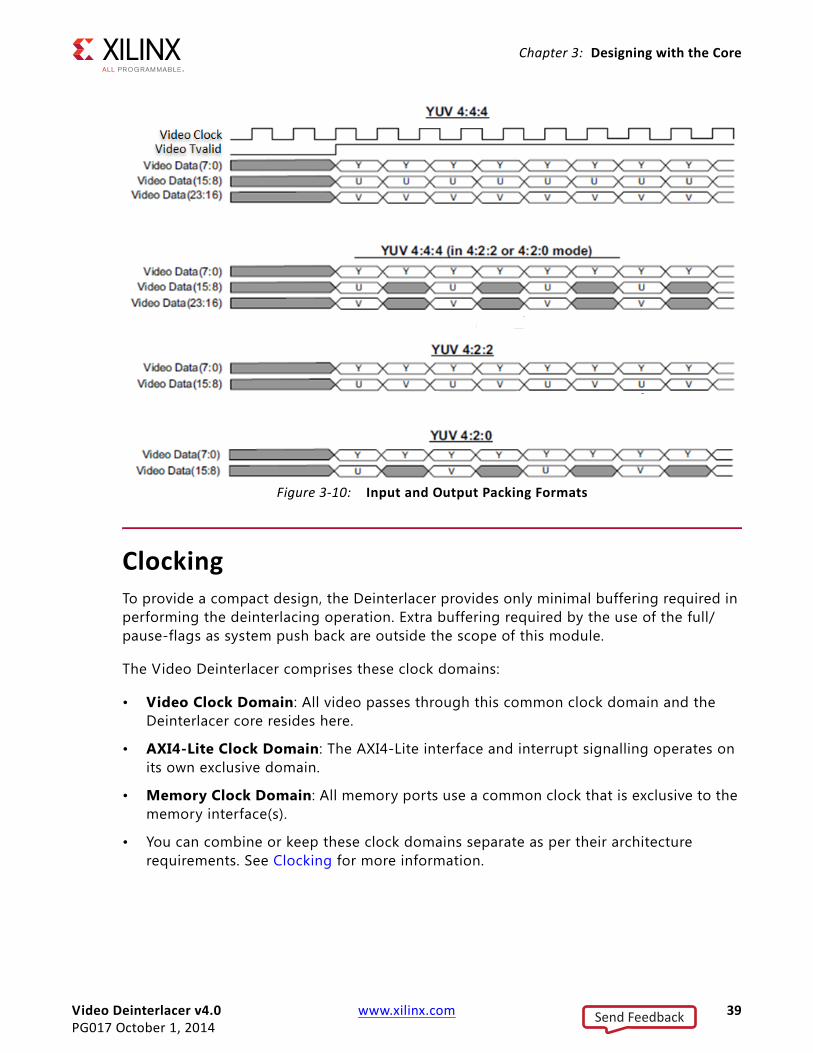
The Video Deinterlacer can process either 4:2:0, 4:2:2 or 4:4:4 video formats. These can either be statically set at core configuration time or can be configured to be dynamically controllable by system software.
Figure 3-10 illustrates the video timing of the various supported packing formats.
X-Ref Target - Figure 3-8
Figure 3-8: Input to Output Video Clock Ratio for SD
X-Ref Target - Figure 3-9
Figure 3-9: Input and Output Video Timing Formats
Send Feedback
Video Deinterlacer v4.0 www.xilinx.com 39PG017 October 1, 2014
Chapter 3: Designing with the Core
ClockingTo provide a compact design, the Deinterlacer provides only minimal buffering required in performing the deinterlacing operation. Extra buffering required by the use of the full/pause-flags as system push back are outside the scope of this module.
The Video Deinterlacer comprises these clock domains:
• Video Clock Domain: All video passes through this common clock domain and the Deinterlacer core resides here.
• AXI4-Lite Clock Domain: The AXI4-Lite interface and interrupt signalling operates on its own exclusive domain.
• Memory Clock Domain: All memory ports use a common clock that is exclusive to the memory interface(s).
• You can combine or keep these clock domains separate as per their architecture requirements. See Clocking for more information.
X-Ref Target - Figure 3-10
Figure 3-10: Input and Output Packing Formats
Send Feedback

Video Deinterlacer v4.0 www.xilinx.com 40PG017 October 1, 2014
Chapter 3: Designing with the Core
ResetsThe Video Deinterlacer core has multiple reset inputs, one for each clock domain. The Video Deinterlacer core comprises these reset inputs.
• Video Clock Domain: aresetn (active Low)
• AXI4-Lite Clock Domain: s_axi_aresetn (active Low)
• Memory Clock Domain: m_axi_aresetn (active Low)
Protocol DescriptionThe Video Deinterlacer core register interface is compliant with the AXI4-Lite interface. The memory interface is compliant with the AXI4 Memory Mapped interface. The Video Deinterlacer input and output interfaces can be configured to be compliant with the AXI4-Stream interface.
Send Feedback

Video Deinterlacer v4.0 www.xilinx.com 41PG017 October 1, 2014
Chapter 4
Design Flow StepsThis chapter describes customizing and generating the core, constraining the core, and the simulation, synthesis and implementation steps that are specific to this IP core. More detailed information about the standard Vivado® design flows in the IP Integrator can be found in the following Vivado Design Suite user guides:
• Vivado Design Suite User Guide: Designing IP Subsystems using IP Integrator (UG994) [Ref 8]
• Vivado Design Suite User Guide: Designing with IP (UG896) [Ref 4]
• Vivado Design Suite User Guide: Getting Started (UG910) [Ref 6]
• Vivado Design Suite User Guide: Logic Simulation (UG900) [Ref 7]
Customizing and Generating the CoreThis section includes information about using Xilinx tools to customize and generate the core in the Vivado® Design Suite.
If you are customizing and generating the core in the Vivado IP Integrator, see the Vivado Design Suite User Guide: Designing IP Subsystems using IP Integrator (UG994) [Ref 8] for detailed information. IP Integrator might auto-compute certain configuration values when validating or generating the design. To check whether the values do change, see the description of the parameter in this chapter. To view the parameter value, run the validate_bd_design command in the Tcl console.
Vivado Integrated Design EnvironmentYou can customize the IP for use in your design by specifying values for the various parameters associated with the IP core using the following steps:
1. Select the IP from the IP catalog.
2. Double-click on the selected IP or select the Customize IP command from the toolbar or popup menu.
For details, see the sections, “Working with IP” and “Customizing IP for the Design” in the Vivado Design Suite User Guide: Designing with IP (UG896) [Ref 4] and the “Working with the
Send Feedback

Video Deinterlacer v4.0 www.xilinx.com 42PG017 October 1, 2014
Chapter 4: Design Flow Steps
Vivado IDE” section in the Vivado Design Suite User Guide: Getting Started (UG910) [Ref 6].
If you are customizing and generating the core in the Vivado IP Integrator, see the Vivado Design Suite User Guide: Designing IP Subsystems Using IP Integrator (UG994) [Ref 8] for detailed information. IP Integrator might auto-compute certain configuration values when validating or generating the design. To check whether the values do change, see the description of the parameter in this chapter. To view the parameter value you can run the validate_bd_design command in the Tcl console.
Note: Figures in this chapter are illustrations of the Vivado IDE. This layout might vary from the current version.
InterfaceThe Deinterlacer core is easily configured to your specific needs through the Vivado IDE. This section provides a quick reference to the parameter that can be configured at generation time. Figure 4-2 and Figure 4-2 show the main and second screen of Deinterlacer, respectively.
Send Feedback

Video Deinterlacer v4.0 www.xilinx.com 43PG017 October 1, 2014
Chapter 4: Design Flow Steps
X-Ref Target - Figure 4-1
Figure 4-1: Vivado GUI Screen
Send Feedback

Video Deinterlacer v4.0 www.xilinx.com 44PG017 October 1, 2014
Chapter 4: Design Flow Steps
The GUI display a representation of the IP symbol on the left side, and the parameter assignment on the right side, which are described as following:
Main Page (Deinterlacer Mode)
• Component Name: the component name is used as the base name of output files generated for the module. Name must begin with a letter and must be composed from characters: a to z, 0 to 9 and "_". The name v_deinterlacer_v4_0 cannot be used as a component name.
• Maximum Active Video Line Width: Specif ies the input pixel height of video frame. ranged from 128 to 2048 pixel lines.
• Video Format: Specifies the color space and packing format. When using IP Integrator, this parameter is automatically computed based on the Video Format of the video IP core connected to the slave AXI-Stream video interface.
X-Ref Target - Figure 4-2
Figure 4-2: Vivado GUI Screen - Page 2
Send Feedback

Video Deinterlacer v4.0 www.xilinx.com 45PG017 October 1, 2014
Chapter 4: Design Flow Steps
• Bit Depth of Color Component: Specif ies the number of bits for each pixel component. Permitted value are 8, 10 and 12 bits.
• Dynamic Colorspace Support: When enabled, the color space is dynamically configurable in the core.
• Include Diagonal Algorithm: When enabled, the diagonal engine is used in the core.
• Include Motion Algorithm: When enabled, the motion adaptive engine is used in the core.
• Include Pulldown/Cadence Detectors: When enabled, the pulldown controller is used in the core.
Second Page (Interface and Protocol Selection)
• AXI4-Lite CPU Base Address: Specifies the base address of CPU domain which also included the AI4-Lite register space.
• AXI4-Lite CPU High Address: Specif ies the high address of CPU domain. The high minus base address must be equal or more than the CPU register address space.
• AXI4-Lite CPU Interface Clock Frequency: Specif ies the clock frequency that used in the CPU AXI4-Lite domain.
• AXI4-Memory Interface Clock Frequency: Specifies the clock frequency that used in the AXI4 - Memory Mapped domain.
• AXI4-Memory Interface Data Width: Specif ies the Data signal width of AXI-Memory Mapped Interface.
• AXI4-Memory Interface Thread Width: Specifies the thread ID width of AXI-Memory Mapped Transaction.
Output GenerationFor details, see “Generating IP Output Products” in the Vivado Design Suite User Guide: Designing with IP (UG896).
Constraining the CoreThis section contains information about constraining the core in the Vivado Design Suite.
Required ConstraintsThe only constraints required are clock frequency constraints for the video clock - aclk, AXI4-lite clock - s_axi_aclk , and AXI Memory Mapped clock - m_axi_aclk . Constraint for m_axi_aclk only required if motion kernel enabled. Paths between these clock
Send Feedback

Video Deinterlacer v4.0 www.xilinx.com 46PG017 October 1, 2014
Chapter 4: Design Flow Steps
domains should be constraint with a max delay constraint and use the datapathonly flag, causing the setup and hold checks to be ignored for the signals that cross clock domains. These constraints are provided in the XDC constraints f ile included with the core.
Device, Package, and Speed Grade SelectionsThere are no Device, Package or Speed Grade requirements for this core.
Clock FrequenciesThere are no specific clock frequency requirements for this core.
This core has not been characterized for use in low power devices.
Clock ManagementThere are no specific Clock management requirements for this core.
Clock PlacementThere are no specific Clock placement requirements for this core.
BankingThere are no specific Banking rules for this core.
Transceiver PlacementThere are no Transceiver Placement requirements for this core.
I/O Standard and PlacementThere are no specific I/O standards and placement requirements for this core.
SimulationThis chapter contains information about simulating IP in the Vivado® Design Suite environment. For comprehensive information about Vivado simulation components, as well as information about using supported third party tools, see the Vivado Design Suite User Guide: Logic Simulation (UG900) [Ref 7].
Send Feedback

Video Deinterlacer v4.0 www.xilinx.com 47PG017 October 1, 2014
Chapter 4: Design Flow Steps
Synthesis and ImplementationFor details about synthesis and implementation, see “Synthesizing IP” and “Implementing IP” in the Vivado Design Suite User Guide: Designing with IP (UG896) [Ref 4].
Send Feedback

Video Deinterlacer v4.0 www.xilinx.com 48PG017 October 1, 2014
Chapter 5
C-Model ReferenceThe Deinterlacer core has a bit accurate C-model designed for system modeling.
Features• Bit-accurate model
• Statically linked library (.lib for Windows)
• Dynamically linked library (.so for Linux)
• Available for 32-bit and 64-bit Windows platforms and 32-bit and 64-bit Linux platform
• Not cycle accurate
• Example C code showing how to use the function is provided
OverviewThe Deinterlacer core has a bit accurate C-model for 32-bit and 64-bit Windows platforms and 32-bit and 64-bit Linux platforms. the model's interface consists of a set of C functions residing in statically linked library (shared library).
See Using the C Model for full details of the interface. A C code example of how to call the model is provided in C Model Example Code.
The model is bit accurate, as it produces exactly the same output data as the core on a frame-by-frame basis. However, the model is not cycle accurate, and it does not model the core's latency or its interface signals.
Unpacking and Model ContentsUnzip the deinterlacer_v4_0_bitacc_model.zip f ile, containing the bit accurate models for the Video Deinterlacer IP Core. This creates the directory structure and f iles in Table 5-1.
Send Feedback

Video Deinterlacer v4.0 www.xilinx.com 49PG017 October 1, 2014
Chapter 5: C-Model Reference
Table 5-1: Bit Accurate C-Model Directory Structures and Files
File Name Contents
deinterlacer_v4_0_bitacc_cmodel.h Model header file
yuv_utils.h header file declaring the YUV image / video container type and support functions including .yuv file I/O
rgb_utils.h header file declaring the RGB image / video container type and support functions
bmp_utils.h header file declaring the bitmap (.bmp) image file I/O functions.
video_utils.h header file declaring the generalized image / video container type, I/O and support functions
video_fio.h header f ile declaring support functions for testbench stimulus f ile I/O
run_bitacc_cmodel.c example code calling the C model
./lin64 Directory containing Precompiled bit accurate ANSI C reference model for simulation on 64-bit Linux platforms.
libIp_deinterlacer_v4_0_bitacc_cmodel.so Model shared object library
run_bitacc_cmodel 64-bit Linux fixed configuration executable
run_bitacc_cmodel_config 64-bit Linux programmable configuration executable
./lin Directory containing Precompiled bit accurate ANSI C reference model for simulation on 32-bit Linux platforms.
libIp_deinterlacer_v4_0_bitacc_cmodel.so
Model shared object library
run_bitacc_cmodel 32-bit Linux fixed configuration executable
run_bitacc_cmodel_config 32-bit Linux programmable configuration executable
./nt64 Directory containing Precompiled bit accurate ANSI C reference model for simulation on 64-bit Windows platforms.
libIp_deinterlacer_v4_0_bitacc_cmodel.dll Precompiled dynamic link library f ile for 64-bit Windows platforms compilation
libIp_deinterlacer_v4_0_bitacc_cmodel.lib Precompiled static library f ile for 64-bit Windows platforms compilation
run_bitacc_cmodel.exe 64-bit Windows f ixed configuration executable
run_bitacc_cmodel_config.exe 64-bit Windows programmable configuration executable
./nt Precompiled bit accurate ANSI C reference model for simulation on 32-bit Windows platforms.
libIp_deinterlacer_v4_0_bitacc_cmodel.dll Precompiled dynamic link library f ile for 32-bit Windows platforms compilation
libIp_deinterlacer_v4_0_bitacc_cmodel.lib Precompiled static library f ile for 32-bit Windows platforms compilation
run_bitacc_cmodel.exe 32-bit Windows f ixed configuration executable
run_bitacc_cmodel_config.exe 32-bit Windows programmable configuration executable
Send Feedback

Video Deinterlacer v4.0 www.xilinx.com 50PG017 October 1, 2014
Chapter 5: C-Model Reference
InstallationFor Linux, make sure the following f iles are in a directory in the $LD_LIBRARY_PATH environment variable:
• libIp_deinterlacer_v4_0_bitacc_cmodel.so
Software RequirementsThe Video Deinterlacer C models were compiled and tested with the software listed in Table 5-2.
Using the C ModelThe bit-accurate C model is accessed through a set of functions and data structures, declared in the header file deinterlacer_v4_0_bitacc_cmodel.h. A higher-level software project may make function-calls to the functions below:
./examples Example input files to be used with the run_bitacc_cmodel executable
FormulaOne_035.yuv Example YUV input f ile
FormulaOne_036.yuv Example YUV input f ile
FormulaOne_037.yuv Example YUV input f ile
FormulaOne_038.yuv Example YUV input f ile
FormulaOne_039.yuv Example YUV input f ile
FormulaOne_040.yuv Example YUV input f ile
FormulaOne_041.yuv Example YUV input f ile
FormulaOne_042.yuv Example YUV input f ile
Table 5-1: Bit Accurate C-Model Directory Structures and Files (Cont’d)
File Name Contents
Table 5-2: Compilation Tools for the Bit Accurate C Models
Platform C Compiler
Linux 32-bit and 64-bit GCC 3.4.6 & 4.1.1
Windows 32-bit and 64-bit Microsoft Visual Studio 2008
Send Feedback

Video Deinterlacer v4.0 www.xilinx.com 51PG017 October 1, 2014
Chapter 5: C-Model Reference
/** * Create a new state structure for this C-Model. * * IMPORTANT: Client is responsible for calling * xilinx_ip_deinterlacer_v4_0_destroy_state() * to free state memory. * * @param generics Generics to be used to configure C-Model * state. * * @returns xilinx_ip_deinterlacer_v4_0_state* Pointer to the internal * state. */struct xilinx_ip_deinterlacer_v4_0_state*xilinx_ip_deinterlacer_v4_0_create_state(struct xilinx_ip_deinterlacer_v4_0_generics generics);
/** * Simulate this bit-accurate C-Model. * * @param state Internal state of this C-Model. State * may span multiple simulations. * @param inputs Inputs to this C-Model. * @param outputs Outputs from this C-Model. * * @returns Exit code Zero for SUCCESS, Non-zero otherwise. */int xilinx_ip_deinterlacer_v4_0_bitacc_simulate( struct xilinx_ip_deinterlacer_v4_0_state* state, struct xilinx_ip_deinterlacer_v4_0_inputs inputs, struct xilinx_ip_deinterlacer_v4_0_outputs* outputs);
Before using the model, the structures holding the generics, inputs, and outputs of the Deinterlacer instance have to be defined:
struct xilinx_ip_deinterlacer_v4_0_generics generics;struct xilinx_ip_deinterlacer_v4_0_inputs inputs;struct xilinx_ip_deinterlacer_v4_0_outputs outputs;
Declaration of the above structures can be found in deinterlacer_v4_0_bitacc_cmodel.h.
Before making the function calls, the following steps are necessary:
1. Populate the 'generics' structure. It defines the values of build-time parameters. Please see Deinterlacer Generics Structure for more information on the structure and an example of how to initialize.
2. Populate the 'inputs' structure. It defines the values of run-time parameters. Please see Deinterlacer Inputs Structure for more information on the structure and an example of how to initialize.
3. Populate the 'outputs' structure. Please see Deinterlacer Outputs Structure for more information on the structure and an example of how to initialize.
Send Feedback

Video Deinterlacer v4.0 www.xilinx.com 52PG017 October 1, 2014
Chapter 5: C-Model Reference
After the inputs are defined and all video_structs initialized the model can be simulated by calling the following functions
state = xilinx_ip_deinterlacer_v4_0_create_state(generics); if (state == NULL) { printf("ERROR: could not create state object\n"); return 1; }
// Simulate the core printf("Running the C model...\n"); if(xilinx_ip_deinterlacer_v4_0_bitacc_simulate(state, inputs, &outputs) != 0) { printf("ERROR: simulation did not complete successfully\n"); return 1; } else { printf("Simulation completed successfully\n"); }
Results are provided in the outputs structure, which contains only one member of type video_struct. More information on the video_struct structure can be found in Deinterlacer Video Structure. Successful execution of all provided functions return value 0, otherwise a non-zero error code indicates that problems were encountered during function calls.
Deinterlacer Generics StructureThe Xilinx LogiCORE IP Video Deinterlacer Core bit accurate C model takes multiple generic parameters. All generic parameters are integers or integer arrays. See Table 5-3 for generic definitions.
Table 5-3: Deinterlacer Generics Structure
Generic Designation
C_STREAMS Number of simultaneous color planesValid values are 2 or 3.
C_DEPTH Bit depth of a pixelValid values are 8, 10 or 12
C_DIAG Enable the diagonal kernel0 = disables the diagonal kernel 1 = enables the diagonal kernel
C_MOTION Enable the motion kernel0 = disables the motion kernel 1 = enables the motion kernel
Send Feedback

Video Deinterlacer v4.0 www.xilinx.com 53PG017 October 1, 2014
Chapter 5: C-Model Reference
Calling xilinx_ip_deinterlacer_v4_0_get_default_generics() initializes the generics structure, xilinx_ip_deinterlacer_v4_0_generics, with the Deinterlacer defaults. An example of initialization of the generics structure is as follows:
generics = xilinx_ip_deinterlacer_v4_0_get_default_generics(); //Get Defaults
Deinterlacer Inputs StructureThe structure xilinx_ip_deinterlacer_v4_0_inputs defines the values of run time parameters and the actual input video frames/images.
struct xilinx_ip_deinterlacer_v4_0_inputs{ struct video_struct video_in; struct deinterlacer_cfg_struct *cfg; struct deinterlacer_pull_struct *pull;
}; // end xilinx_ip_deinterlacer_v4_0_inputs
The video_in variable is an array of video_struct structures, one structure per layer. See the Deinterlacer Video Structure for a description of the video_in structure. The video_in structure must be initialized.
C_PULLDOWN Cadence/Pull-down detection0 = No pull-down detection1 = Full pull-down detection
C_COL Static color space setting0 = YUV1 = RGB
Table 5-3: Deinterlacer Generics Structure (Cont’d)
Generic Designation
Send Feedback

Video Deinterlacer v4.0 www.xilinx.com 54PG017 October 1, 2014
Chapter 5: C-Model Reference
Deinterlacer Config StructureThe cfg variable is a pointer to the deinterlacer_cfg_struct. The deinterlacer_cfg_struct is defined as:
struct deinterlacer_cfg_struct{ int frame; int bmpfiles; int txtfiles; int rate; int t1; int t2; int pull_lo; int pull_hi; int pixel_scale; int filewidth; int fileheight; int depth; int format; int mode; int order; int pulldown; int cropx; int cropy; int width; int height; int length; int index; int debug; int pixel_mask; char source[256]; char prefix[256]; char num_len; char suffix[256]; char golden[256]; FILE *avifile;
int lut[4096];
};
Send Feedback

Video Deinterlacer v4.0 www.xilinx.com 55PG017 October 1, 2014
Chapter 5: C-Model Reference
Pull-down StructureThe pull variable is a pointer to the deinterlacer_pull_struct. The deinterlacer_pull_struct is defined as:
struct deinterlacer_pull_struct{ // Internal 22 State Machine int trained_22; int trained_22_d1; int last_22_delta; int confidence_22;
// Internacer 32 State Machine int cx_32; int switch_32; int next_field_32; int bad_time_32; int bad_32; int trained_32; int trained_32_d1; int state_32; int p24_32; // Top level cotrol int active_32_early; int active_32; int active_22_early; int active_22; int mux_switch; int next_field; int p24;};
Deinterlacer Outputs StructureThe structure xilinx_ip_deinterlacer_v4_0_outputs provides the actual output video frames/images of the Deinterlacer core. This structure is a wrapper to the standard video_struct used by other Xilinx video core C models.
struct xilinx_ip_ deinterlacer_v4_0_outputs{struct video_struct video_out;}; // xilinx_ip_deinterlacer_v4_0_outputsThe video_out structure must be initialized. The following code shows a typicalvideo_out initialization.// Setup Output Video Bufferoutputs.video_out.frames = inputs.num_frames;outputs.video_out.rows = inputs.frame_cfg->y_size;outputs.video_out.cols = inputs.frame_cfg->x_size;outputs.video_out.mode = FORMAT_C444;outputs.video_out.bits_per_component = generics.C_DATA_WIDTH;outputs.video_out.data[0] = NULL;outputs.video_out.data[1] = NULL;outputs.video_out.data[2] = NULL;
Send Feedback

Video Deinterlacer v4.0 www.xilinx.com 56PG017 October 1, 2014
Chapter 5: C-Model Reference
Deinterlacer Video StructureInput images or video streams can be provided to the Deinterlacer v4.0 reference model using the video_struct structure, defined in video_utils.h. Output images or video streams are also placed within a video_struct structure. The video_struct is defined as:
struct video_struct{ int frames, rows, cols, bits_per_component, mode; uint16*** data[5]; };
The structure member variables are defined in Table 5-4.
Table 5-5 shows the named constants for video modes with corresponding planes and representations.
Table 5-4: Member Variables of the Video Structure
Member Variable Designation
frames Number of video/image frames in the data structure
rows Number of rows per framePertains to the image plane with the most rows and columns, such as the luminance channel for YUV data. Frame dimensions are assumed constant through the all frames of the video stream, however different planes, such as y, u and v can have different smaller dimensions.
cols Number of columns per framePertains to the image plane with the most rows and columns, such as the luminance channel for YUV data. Frame dimensions are assumed constant through the all frames of the video stream, however different planes, such as y, u and v can have different smaller dimensions.
bits_per_component Number of bits per color channel/component.All image planes are assumed to have the same color/ component representation. Maximum number of bits per component is 16.
mode Contains information about the designation of data planes.Named constants to be assigned to mode are listed in Table 5-5.
data Of 5 pointers to 3 dimensional arrays containing data for image planes. data is in 16 bit unsigned integer format accessed as data[plane][frame][row][col]
Table 5-5: Named Constants for Video Modes
Mode Planes Video Representation
FORMAT_MONO 1 Monochrome - Luminance only.
FORMAT_RGB 3 RGB image / video data
FORMAT_C444 3 4:4:4 YUV, or YCrCb image / video data
FORMAT_C422 3 4:2:2 format YUV video, (u,v chrominance channels horizontallysub-sampled)
Send Feedback

Video Deinterlacer v4.0 www.xilinx.com 57PG017 October 1, 2014
Chapter 5: C-Model Reference
Working With video_struct ContainersThe video_utils.h f ile defines functions to simplify access to video data in video_struct.
int video_planes_per_mode(int mode);int video_rows_per_plane(struct video_struct* video, int plane);int video_cols_per_plane(struct video_struct* video, int plane);
Function video_planes_per_mode returns the number of component planes defined by the mode variable, as described in Table 5-5. Functions video_rows_per_plane and video_cols_per_plane return the number of rows and columns in a given plane of the selected video structure. The following example demonstrates using these functions in conjunction to process all pixels within a video stream stored in variable in_video, with this construct:
for (int frame = 0; frame < in_video->frames; frame++) { for (int plane = 0; plane < video_planes_per_mode(in_video->mode); plane++) { for (int row = 0; row < rows_per_plane(in_video,plane); row++) { for (int col = 0; col < cols_per_plane(in_video,plane); col++) { // User defined pixel operations on // in_video->data[plane][frame][row][col] } } }}
Delete the Video StructureLarge arrays such as the video_in element in the video structure must be deleted to free up memory. As an example, the following function is defined as part of the video_utils package.
void free_video_buff(struct video_struct* video ) { int plane, frame, row;
FORMAT_C420 3 4:2:0 format YUV video, ( u,v sub-sampled both horizontally andvertically )
FORMAT_MONO_M 3 Monochrome (Luminance) video with Motion.
FORMAT_RGBA 4 RGB image / video data with alpha (transparency) channel
FORMAT_C420_M 5 4:2:0 YUV video with Motion or Alpha
FORMAT_C422_M 5 4:2:2 YUV video with Motion or Alpha
FORMAT_C444_M 5 4:4:4 YUV video with Motion or Alpha
FORMAT_RGBM 5 RGB video with Motion
Table 5-5: Named Constants for Video Modes (Cont’d)
Mode Planes Video Representation
Send Feedback

Video Deinterlacer v4.0 www.xilinx.com 58PG017 October 1, 2014
Chapter 5: C-Model Reference
if (video->data[0] != NULL) { for (plane = 0; plane <video_planes_per_mode(video->mode); plane++) { for (frame = 0; frame < video->frames; frame++) { for (row = 0; row<video_rows_per_plane(video,plane); row++) { free(video->data[plane][frame][row]); } free(video->data[plane][frame]); } free(video->data[plane]); } } }
This function can be called in the following way to free the video input buffers (up to eight) and the video output buffer:
// Free Layer Buffersfor(i=0; i < generics.C_NUM_LAYERS; i++){printf("Freeing Layer Video Buffer #%d...\n", i);free_video_buff(&inputs.video_in[i]);}printf("Freeing Output Buffer...\n");free_video_buff(&outputs.video_out);
C Model Example CodeTwo example C f iles, run_bitacc_cmodel.c and run_bitacc_cmodel_config.c, are provided. The 32-bit and 64-bit Windows and Linux executables for these examples are also included.
The run_bitacc_cmodel example executable provides:
• Shows a f ixed implementation of the Deinterlacer
• Contains an example of how to write an application that makes all necessary function calls to the Deinterlacer C model core function.
• Contains an example of how to populate the video structures at the input and output, including allocation of memory to these structures.
• Uses a YUV file reading function to extract video information from YUV files for use by the model.
• Uses a YUV file writing function to provide an output YUV file, which allows the user to visualize the result of the core.
The run_bitacc_cmodel example executable does not use command line parameters. To run the executable:
1. Use the cd command to go to the platform directory (lin64, lin, win64 or win32).
Send Feedback

Video Deinterlacer v4.0 www.xilinx.com 59PG017 October 1, 2014
Chapter 5: C-Model Reference
2. Enter this command at the shell or DOS prompt:
run_bitacc_cmodel
The run_bitacc_cmodel_config example executable provides:
• Shows configurable implementations of the Deinterlacer configured from command line arguments.
• Includes a command line parser, allowing the user to pass parameters into the model for multiple test cases.
• Uses YUV or BMP file reading functions to extract video information from YUV or BMP files for use by the model.
• Uses YUV or BMP file writing functions to provide an output YUV or BMP file, which allows the user to visualize the result of the core.
The run_bitacc_cmodel_config example executable uses multiple command line parameters. To run the executable:
1. Use the cd command to go to the platform directory (lin64, lin, win64 or win32).
2. Enter this command at the shell or DOS prompt:
./run_bitacc_cmodel_config <-parameter> <value> …
For example:
run_bitacc_cmodel_config -width 720 -height 576 -depth 8 -mode full -length 2 -source test_000.yuv
Command Line Options in DetailThe following is a detailed list of the options:
• -core: selects which gate-level model is run; excluding this option defaults to RTL simulation.
• -format: selects the input f ile format; possible input formats are 422YUV8, 422YUV10, 444BMP.
• -rate: selects output frame rate.
• -order : selects which f ield order is used to store the source files. By choosing "pal", line 1 is temporally used before line 2. By choosing NTSC, this order is reversed,
• -pulldown: selects the operation of the pulldown detector; it can be either switched on or off.
• -mode: selects what internal processing is used to generate a deinterlaced image. If "none" is selected, the output is f ield interpolated. If "motion" is selected, then only
Send Feedback

Video Deinterlacer v4.0 www.xilinx.com 60PG017 October 1, 2014
Chapter 5: C-Model Reference
the motion adaptive algorithm is used. If "diag" is selected, then only the diagonal algorithm is used. If "full", then all features are enabled.
• -cropx, -cropy, -cropxsize, -cropysize: allow for a region of interest to be extracted from a given source image; the origin of a picture is assumed to be 0,0 and only even x offsets are allowed.
• -width: sets the full pixel width of the input file image and is required.
• -height: sets the full pixel height of the input f ile image and is required.
• -length: sets the number of f iles read by the chosen core; it should be set greater than three to allow enough priming of the motion adaptive datapath.
• -txt: used by the C model to generate a .txt equivalent f ile set of the source images, which are then used by the VHDL or Verilog models.
• -source: path and file name of the f irst f ile to be read.
• -debug: enables colorized images to be generated.
The main parameters are used to steer the test and its target. The options for a test are shown in Table 5-6.
Table 5-6: Simulation Options
Option Name Description Option Values Default
depth Bit depth of video stream 8 | 10 | 12 10
format File format used yuv8 | yuv10 | bmp| yuv8
packing Pixel packing structure 444 | 422 | 420 444
pulldown Cadence detector off | on off
mode Deinterlacing type full | none | motion | diag full
cropx Cropping Top Left X <numeric value> 0
cropy Cropping Top Left Y <numeric value> 0
cropxsize Cropping X size <numeric value> <default to width>
cropysize Cropping Y size <numeric value> <default to height>
width Input File Pixel width <numeric value> <error if missing>
height Input File Pixel height <numeric value> <error if missing>
length Number of f iles in sequence <numeric value> <error if missing>
source Sequence f ilename <filename> <error if missing>
golden Sequence f ilename <filename> <used only by compare>
debug Generate debug images <numeric value> 0
Send Feedback

Video Deinterlacer v4.0 www.xilinx.com 61PG017 October 1, 2014
Chapter 5: C-Model Reference
Initializing the Deinterlacer Input Video StructureThe easiest way to assign stimuli values to the input video structure is to initialize it with an image or video. The bmp_util.h, yuv_utils.h, rgb_utils.h and video_util.h header f iles packaged with the bit accurate C models contain functions to facilitate file I/O.
Bitmap Image Files
The rgb_utils.h and bmp_utils.h f iles declare functions that help access f iles in Windows bitmap format (http://en.wikipedia.org/wiki/BMP_file_format). However, this format limits color depth to a maximum of 8 bits per pixel, and operates on images with three planes (R,G,B). Consequently, the following functions operate on arguments type rgb8_video_struct, which is defined in rgb_utils.h. Also, both functions support only true color, non-indexed formats with 24 bits per pixel.
int write_bmp(FILE *outfile, struct rgb8_video_struct *rgb8_video);int read_bmp(FILE *infile, struct rgb8_video_struct *rgb8_video);
These functions are used to dynamically allocate and free memory for RGB structure storage:
int alloc_rgb8_frame_buff(struct rgb8_video_struct* rgb8video );void free_rgb_frame_buff(struct rgb_video_struct* rgb_video );
Exchanging data between rgb8_video_struct and general video_struct type frames/videos is facilitated by functions:
int copy_rgb8_to_video(struct rgb8_video_struct* rgb8_in,struct video_struct* video_out );int copy_video_to_rgb8( struct video_struct* video_in,struct rgb8_video_struct* rgb8_out );
Note: All image / video manipulation utility functions expect both input and output structures initialized; for example, pointing to a structure that has been allocated in memory, either as static or dynamic variables. Additionally, the input structure must have the dynamically allocated containers (data, r, g, b, y, u, and v arrays) already allocated and initialized with the input frame(s). If the output container structure is pre-allocated at the time of the function call, the utility functions verify and issue an error if the output container size does not match the size of the expected output. If the output container structure is not pre-allocated, the utility functions create the appropriate container to hold results.
YUV Image/Video Files
The yuv_utils.h f ile declares functions that support f ile access in YUV format. These functions are used to dynamically allocate and free memory for YUV structure storage:
int alloc_yuv8_frame_buff(struct yuv8_video_struct* yuv8video );void free_yuv_frame_buff(struct yuv_video_struct* yuv_video );
These functions allow reading and writing of YUV functions (used to initialize or write yuv8_video data):
Send Feedback

Video Deinterlacer v4.0 www.xilinx.com 62PG017 October 1, 2014
Chapter 5: C-Model Reference
int write_yuv(FILE *outfile, struct yuv8_video_struct *yuv8_video);int read_yuv(FILE *infile, struct yuv8_video_struct *yuv8_video);
Exchanging data between yuv8_video_struct and general video_struct type frames/ videos is facilitated by functions:
int copy_yuv8_to_video(struct yuv8_video_struct* yuv8_in,struct video_struct* video_out );int copy_video_to_yuv8( struct video_struct* video_in,struct yuv8_video_struct* yuv8_out );
YUV formats (4:2:0, 4:2:2 and 4:4:4) can be converted with these functions:
int yuv8_420to444(struct yuv8_video_struct* video_in, struct yuv8_video_struct* video_out);int yuv8_422to444(struct yuv8_video_struct* video_in, struct yuv8_video_struct* video_out);int yuv8_444to420(struct yuv8_video_struct* video_in, struct yuv8_video_struct* video_out);int yuv8_444to422(struct yuv8_video_struct* video_in, struct yuv8_video_struct* video_out);
Binary Image/Video Files
The video_utils.h f ile declares functions that help load and save generalized video f iles in raw, uncompressed format. These functions effectively serialize the video_struct structure:
int read_video( FILE* infile, struct video_struct* in_video);int write_video(FILE* outfile, struct video_struct* out_video);
The corresponding file contains a small, plain text header defining, "Mode", "Frames", "Rows", "Columns", and "Bits per Pixel". The plain text header is followed by binary data, 16-bits per component in scan line continuous format. Subsequent frames contain as many component planes as defined by the video mode value selected. Also, the size (rows, columns) of component planes can differ within each frame as defined by the actual video mode selected.
These functions are used to dynamically allocate and free memory for video structure storage:
int alloc_video_buff(struct video_struct* video );void free_video_buff(struct video_struct* video );
Compiling on 32-bit and 64-bit Windows Platforms Precompiled library deinterlacer_v4_0_bitacc_cmodel.lib, top level demonstration code run_bitacc_cmodel_config.c and example code run_bitacc_cmodel.c must be compiled with an ANSI C compliant compiler under Windows 32-bit or Windows 64-bit. This section describes an example using Microsoft Visual Studio. In Visual Studio create a new, empty Win32 Console Application project. As existing items, add:
Send Feedback

Video Deinterlacer v4.0 www.xilinx.com 63PG017 October 1, 2014
Chapter 5: C-Model Reference
• libIpdeinterlacer_v4_0_bitacc_cmodel.lib to the "Resource Files" folder of the project
• run_bitacc_cmodel.c or the run_bitacc_cmodel_config.c to the "Source Files" folder of the project
• deinterlacer_v4_0_bitacc_cmodel.h header f ile to the "Header Files" folder of the project
• bmp_utils.h f ile to the "Header Files" folder of the project
• rgb_utils.h f ile to the "Header Files" folder of the project
• video_fio.h f ile to the "Header Files" folder of the project
• video_utils.h f ile to the "Header Files" folder of the project
• yuv_utils.h f ile to the "Header Files" folder of the project
To build the x64 executable for 64-bit Windows platforms, perform these steps. These steps can be skipped if building the Win32 executable.
1. Right-click on the solution in the Solution Explorer and click Properties at the bottom of the pop-up menu.
2. Click Configuration Manager.
3. In the Active solution platform drop-down box, select <New…>.
4. In the new platform drop-down box, select x64 and click OK. Make sure that all the projects now have x64 as the default platform in the Configuration Manager.
5. After the project is created and populated, it must be compiled and linked (built) to create a Win32 or x64 executable. To perform the build step, select Build Solution from the Build menu. An executable matching the project name is created either in the Debug or Release subdirectories under the project location based on whether "Debug" or "Release" has been selected in the "Configuration Manager" under the Build menu.
Note: The run_bitacc_cmodel.c f ile is an example demonstration that reads no input but generates an output .yuv f ile from internally generated test patterns. The run_bitacc_cmodel_config.c f ile is a configurable demonstration and requires several input f iles to run. See Running the Executables for information on command line arguments and input f ile formats.
Compiling under 32-bit and 64-bit Linux Platforms
Example Demonstration
To compile the example demonstration, go to the directory where the header files, the library f iles and run_bitacc_cmodel.c were unpacked. The libraries and header files are
Send Feedback

Video Deinterlacer v4.0 www.xilinx.com 64PG017 October 1, 2014
Chapter 5: C-Model Reference
referenced during the compilation and linking process. In this directory, perform these steps:
1. Set your LD_LIBRARY_PATH environment variable to include the root directory where the model zip f ile was unzipped. For example:
setenv LD_LIBRARY_PATH <unzipped_c_model_dir>:${LD_LIBRARY_PATH}
2. Copy this f ile from the /lin32 or /lin64 directory to the root directory:
libIp_deinterlacer_v4_0_bitacc_cmodel.so
3. In the root directory, compile using the GNU C Compiler by typing this command at the shell prompt:
gcc -m32 -x c++ ../run_bitacc_cmodel.c ../parsers.c -orun_bitacc_cmodel -L. -lIp_deinterlacer_v4_0_bitacc_cmodel -Wl,-rpath,.gcc -m64 -x c++ ../run_bitacc_cmodel.c ../parsers.c -orun_bitacc_cmodel -L. -lIp_deinterlacer_v4_0_bitacc_cmodel -Wl,-rpath,.
4. This results in the creation of the executable run_bitacc_cmodel, which can be run using this command:
./run_bitacc_cmodel
A make f ile is also included that runs GCC. To clean the executable and compile the example code, enter this command at the shell prompt:
make clean all
Configurable Demonstration
To compile the configurable demonstration, go to the directory where the header files, the library f iles and run_bitacc_cmodel_config.c were unpacked. The libraries and header f iles are referenced during the compilation and linking process. In this directory perform these steps:
1. Set your LD_LIBRARY_PATH environment variable to include the root directory where the model zip-file was unzipped. For example:
setenv LD_LIBRARY_PATH <unzipped_c_model_dir>:${LD_LIBRARY_PATH}
2. Copy this f ile from the /lin64 directory to the root directory:
libIp_deinterlacer_v4_0_bitacc_cmodel.so
3. In the root directory, compile using the GNU C Compiler by entering this command at the shell prompt:
gcc -x c++ run_bitacc_cmodel_config.c -o run_bitacc_cmodel_config -L.-lIp_deinterlacer_v4_0_bitacc_cmodel -Wl,-rpath,.
4. This results in the creation of the executable run_bitacc_cmodel, which can be run using this command:
Send Feedback
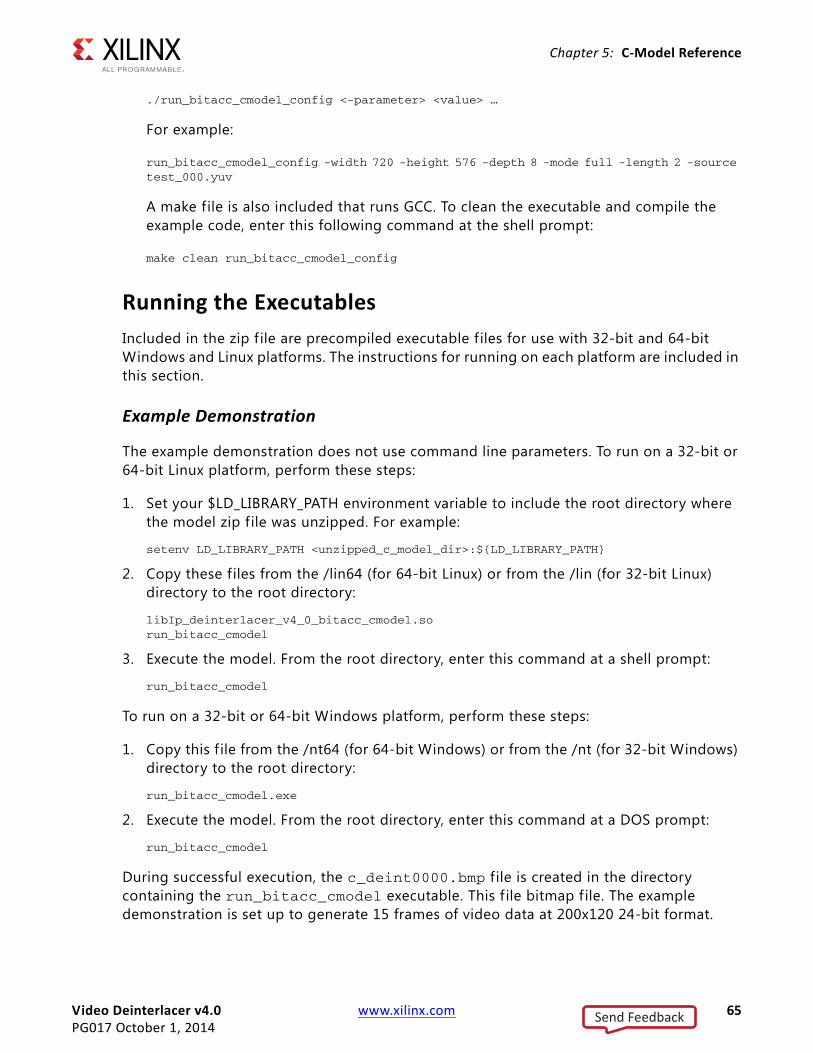
Video Deinterlacer v4.0 www.xilinx.com 65PG017 October 1, 2014
Chapter 5: C-Model Reference
./run_bitacc_cmodel_config <-parameter> <value> …
For example:
run_bitacc_cmodel_config -width 720 -height 576 -depth 8 -mode full -length 2 -source test_000.yuv
A make f ile is also included that runs GCC. To clean the executable and compile the example code, enter this following command at the shell prompt:
make clean run_bitacc_cmodel_config
Running the ExecutablesIncluded in the zip f ile are precompiled executable f iles for use with 32-bit and 64-bit Windows and Linux platforms. The instructions for running on each platform are included in this section.
Example Demonstration
The example demonstration does not use command line parameters. To run on a 32-bit or 64-bit Linux platform, perform these steps:
1. Set your $LD_LIBRARY_PATH environment variable to include the root directory where the model zip file was unzipped. For example:
setenv LD_LIBRARY_PATH <unzipped_c_model_dir>:${LD_LIBRARY_PATH}
2. Copy these files from the /lin64 (for 64-bit Linux) or from the /lin (for 32-bit Linux) directory to the root directory:
libIp_deinterlacer_v4_0_bitacc_cmodel.sorun_bitacc_cmodel
3. Execute the model. From the root directory, enter this command at a shell prompt:
run_bitacc_cmodel
To run on a 32-bit or 64-bit Windows platform, perform these steps:
1. Copy this f ile from the /nt64 (for 64-bit Windows) or from the /nt (for 32-bit Windows) directory to the root directory:
run_bitacc_cmodel.exe
2. Execute the model. From the root directory, enter this command at a DOS prompt:
run_bitacc_cmodel
During successful execution, the c_deint0000.bmp f ile is created in the directory containing the run_bitacc_cmodel executable. This f ile bitmap file. The example demonstration is set up to generate 15 frames of video data at 200x120 24-bit format.
Send Feedback

Video Deinterlacer v4.0 www.xilinx.com 66PG017 October 1, 2014
Chapter 5: C-Model Reference
Configurable Demonstration
The configurable demonstration takes multiple command line parameters. To run on a 32-bit or 64-bit Linux platform, perform these steps:
1. Set your $LD_LIBRARY_PATH environment variable to include the root directory where the model zip-file was unzipped. For example:
setenv LD_LIBRARY_PATH <unzipped_c_model_dir>:${LD_LIBRARY_PATH}
2. Copy these files from the /lin64 (for 64-bit Linux) or from the /lin (for 32-bit Linux) directory to the root directory:
libIp_deinterlacer_v4_0_bitacc_cmodel.sorun_bitacc_cmodel_config
3. Execute the model. From the root directory, enter this command at a shell prompt:
./run_bitacc_cmodel_config <-parameter> <value> …
For example:
run_bitacc_cmodel_config -width 720 -height 576 -depth 8 -mode full -length 2 -source test_000.yuv
To run on a 32-bit or 64-bit Windows platform, perform these steps:
1. Copy this f ile from the /nt64 (for 64-bit Windows) or from the /nt (for 32-bit Windows) directory to the root directory:
run_bitacc_cmodel_config.exe
2. Execute the model. From the root directory, enter this command at a DOS prompt:
./run_bitacc_cmodel_config <-parameter> <value> …
For example:
run_bitacc_cmodel_config -width 720 -height 576 -depth 8 -mode full -length 2 -source test_000.yuv
During successful execution, multiple bitmap files are created in the directory containing the run_bitacc_cmodel_config executable.
Each individual simulation is invoked using a binary executable script and some command line parameters.
The "source", "length", "width" and "height" parameters are mandatory, all other missing f ields are set to their default.
The following command line shows how to run a C model based, 8-bit full Deinterlacer on sequence files "test000":
run_bitacc_cmodel_config -width 720 -height 576 -depth 8 -mode full -length 2 -source test_000.yuv
Send Feedback

Video Deinterlacer v4.0 www.xilinx.com 67PG017 October 1, 2014
Chapter 5: C-Model Reference
When running the C model output, two additional AVI f iles are generated. The first is an animated version of the full deinterlaced sequence, and the second is a side-by-side comparison movie of the motion adaptive and full Deinterlacer in operation. This second AVI f ile allows for easy visual comparison of the outputs. The user can preset the AVI frame rate on the command line.
Send Feedback

Video Deinterlacer v4.0 www.xilinx.com 68PG017 October 1, 2014
Chapter 6
Detailed Example DesignThe Deinterlacer is typically used in the broadcast video conversions of SD and HD material to progressive formats for subsequent display on a display monitor.
Case 1: SD480i to SD480pAnother typical use of the Deinterlacer is for the conversion of NTSC to 480p video. In this application, the Deinterlacer uses the AXI4-Lite interface and the configuration values are dynamically set by the system software.
The core is configured to process an 8-bit 4:2:2 YUV stream coming from an AXI4-Stream. The T1, T2 and cross fade ratio settings are wired to their default values. Full deinterlacing is enabled.
Given a pixel rate of 13.5 MHz for SD video, the video clock required is at least 27 MHz as shown in Figure 6-1. This can be derived from the incoming video and passed through a DCM to double the clock rate.
X-Ref Target - Figure 6-1
Figure 6-1: Example SD Data Path
Send Feedback

Video Deinterlacer v4.0 www.xilinx.com 69PG017 October 1, 2014
Chapter 6: Detailed Example Design
The memory clock is set by considering the bit depth and pixel rate. Since 8-bit video is used, the packing ratio is 5/4. A safety margin of 70% AXI4-MM utilization is used. Taking these factors into account, the minimum memory clock rate is:
Memory clock = [13.5 MHz * (5/4) *] / 0.70 = 24.1 MHz
The SDI system clock minimum is 13.5 MHz. Using a minimal clock approach, the video clock and memory clock can be connected and run at a common multiple of 13.5 MHz.27 MHz is the f irst DCM multiple to satisfy the requirements of both the memory clock and video clock.
The memory bandwidth can now be determined. The Deinterlacer has three memory streams, so the effective memory bandwidth of SD is:
24.1 MWords/Second * 3 streams = 72.3 MW/s or 289 Mbytes/s or 2.3 Gbps
Case 2: HD1080i to HD1080pAnother typical use of the Deinterlacer is for the conversion of 1080iHD to 1080pHD video. In this application, the Deinterlacer uses the AXI4-Lite interface and the configuration values are dynamically set by the system software.
The core is configured to process a 12-bit 4:4:4 YUV stream from a AXI4-Stream. The T1, T2 and cross fade ratio settings are set to their default values; full deinterlacing is enabled.
Given a pixel rate of 74.25 MHz for HD video, the video clock required is at least 148.5 MHz as shown in Figure 6-2.
X-Ref Target - Figure 6-2
Figure 6-2: Example HD Data Path
Send Feedback

Video Deinterlacer v4.0 www.xilinx.com 70PG017 October 1, 2014
Chapter 6: Detailed Example Design
The memory clock is set by considering the bit depth and pixel rate. Using 12-bit video, the packing ratio is 3/4, and with a safety margin of 60% AXI4-MM utilization, the minimum memory clock rate is:
Memory clock = [74.25 MHz * (3/2) ] / 0.60 = 185 MHz
The memory bandwidth can now be determined. The Deinterlacer has three memory streams, so the effective memory bandwidth of SD is:
185 MWords/Second * 3 streams = 556 MW/s or 2.2 GBytes/s or 17.82 Gbps
For example, selecting a 32-bit DDR interface with a fabric clock rate of 200 MHz, physical clock rate of 400 MHz and DDR3-800 device, the theoretical bandwidth is 3.2 GBytes/s. This device configuration would sustain the Deinterlacer, leaving 1 GB/s for other applications.
Send Feedback
Video Deinterlacer v4.0 www.xilinx.com 71PG017 October 1, 2014
Chapter 7
Test BenchThis chapter contains information about the provided test bench in the Vivado® Design Suite environment.
Demonstration Test BenchA demonstration test bench is provided with the core which enables you to observe core behavior in a typical scenario. This test bench is generated together with the core in Vivado Design Suite. You are encouraged to make simple modif ications to the configurations and observe the changes in the waveform.
Directory and File ContentsThe following files are expected to be generated in the in the demonstration test bench output directory:
• axi4lite_mst.v
• axi4s_video_mst.v
• axi4s_video_slv.v
• ce_generator.v
• tb_<IP_instance_name>.v
Test Bench StructureThe top-level entity is tb_<IP_instance_name>.
It instantiates the following modules:
• DUT
The <IP> core instance under test.
• axi4lite_mst
Send Feedback

Video Deinterlacer v4.0 www.xilinx.com 72PG017 October 1, 2014
Chapter 7: Test Bench
The AXI4-Lite master module, which initiates AXI4-Lite transactions to program core registers.
• axi4s_video_mst
The AXI4-Stream master module, which generates ramp data and initiates AXI4-Stream transactions to provide video stimuli for the core and can also be used to open stimuli f iles generated from the reference C models and convert them into corresponding AXI4-Stream transactions.
To do this, edit tb_<IP_instance_name>.v:
a. Add define macro for the stimuli f ile name and directory pathdefine STIMULI_FILE_NAME<path><filename>.
b. Comment-out/remove the following line:MST.is_ramp_gen(`C_ACTIVE_ROWS, `C_ACTIVE_COLS, 2);and replace with the following line:MST.use_file(`STIMULI_FILE_NAME);
For information on how to generate stimuli f iles, see Chapter 4, C Model Reference.
• axi4s_video_slv
The AXI4-Stream slave module, which acts as a passive slave to provide handshake signals for the AXI4-Stream transactions from the core output, can be used to open the data files generated from the reference C model and verify the output from the core.
To do this, edit tb_<IP_instance_name>.v:
a. Add define macro for the golden f ile name and directory pathdefine GOLDEN_FILE_NAME “<path><filename>”.
b. Comment out the following line:SLV.is_passive;and replace with the following line:SLV.use_file(`GOLDEN_FILE_NAME);
For information on how to generate golden f iles, see Chapter 4, C Model Reference.
• ce_gen
Programmable Clock Enable (ACLKEN) generator.
Send Feedback

Video Deinterlacer v4.0 www.xilinx.com 73PG017 October 1, 2014
Appendix A
Verification, Compliance, and Interoperability
SimulationA validation suite consisting of a precompiled Windows C model and RTL test bench framework is included with the Video Deinterlacer. Both environments allow users to stream their own 24-bit true color BMP or YUV8/YUV10 files into the simulator and produce real BMP output f iles. This advantage allows for real world examples to be tested with the Deinterlacer in advance. Additionally, BMP files are also generated by the C model, allowing users to view animated results of the simulation in their chosen video program.
Additional system simulation and FPGA colorization is available via the AXI4-Lite interface to illustrate the algorithms operation and decision matrix in live operation. This can be useful if dynamic control of the thresholds is done by the system software. Figure A-1 shows a normal fully deinterlaced output. Note the smoothed lines of the Deinterlacer.
X-Ref Target - Figure A-1
Figure A-1: No Colorization
Send Feedback

Video Deinterlacer v4.0 www.xilinx.com 74PG017 October 1, 2014
Appendix A: Verification, Compliance, and Interoperability
Figure A-2 is the same image with full diagonal colorization enabled. The green highlight shows the diagonal edges that were detected and then enhanced.
Figure A-3 is the same image with full motion colorization enabled. The three lines are moving upward. The three trailing motion vectors are in red around each white line. The red lines show the front and back edge motion of the line.
Hardware TestingThe Video Deinterlacer has been verif ied in the KC705 Kintex-7 FPGA Platform.
X-Ref Target - Figure A-2
Figure A-2: Diagonal Colorization
X-Ref Target - Figure A-3
Figure A-3: Motion Colorization
Send Feedback

Video Deinterlacer v4.0 www.xilinx.com 75PG017 October 1, 2014
Appendix B
MigratingThis appendix contains information about migrating a design from ISE® to the Vivado® Design Suite, and for upgrading to a more recent version of the IP core. For customers upgrading in the Vivado Design Suite, important details (where applicable) about any port changes and other impact to user logic are included.
Migrating to the Vivado Design SuiteFor information about migrating to the Vivado Design Suite, see the ISE to Vivado Design Suite Migration Guide (UG911) [Ref 3].
Upgrading in the Vivado Design SuiteThis section provides information about any changes to the user logic or port designations that take place when you upgrade to a more current version of this IP core in the Vivado Design Suite.
From version v3.00.a to v4.0 of the deinterlacer core the following signif icant changes look place:
• The core is for native Vivado design tools release.
• Removal of XSVI ports and has f ixed to AXI4-Stream protocol only.
• Core upgrade from v3.00.a to v4.0 in Vivado will replace both GUI options for static color space and number of color planes with only one GUI option - video format. Also remove the selection for XSVI ports.
• Core upgrade from v2.00.a to v4.0 in Vivado will replace both GUI options for static color space and number of color planes with only one GUI option - video format. Also remove the selection for XSVI ports and GPP ports.
Parameter Changes There were no parameter changes in the XCO file.
Send Feedback

Video Deinterlacer v4.0 www.xilinx.com 76PG017 October 1, 2014
Appendix B: Migrating
Port ChangesThere is only one type of data stream interface which is AXI4-Stream.
Other ChangesThe Deinterlacer’s internal algorithms have not changed in this revision.
Send Feedback

Video Deinterlacer v4.0 www.xilinx.com 77PG017 October 1, 2014
Appendix C
DebuggingThis appendix includes details about resources available on the Xilinx Support website and debugging tools.
Finding Help on Xilinx.comTo help in the design and debug process when using the Video Deinterlacer core, the Xilinx Support web page (www.xilinx.com/support) contains key resources such as product documentation, release notes, answer records, information about known issues, and links for opening a Technical Support WebCase.
DocumentationThis product guide is the main document associated with the Video Deinterlacer core. This guide, along with documentation related to all products that aid in the design process, can be found on the Xilinx Support web page (www.xilinx.com/support) or by using the Xilinx Documentation Navigator.
Download the Xilinx Documentation Navigator from the Design Tools tab on the Downloads page (www.xilinx.com/download). For more information about this tool and the features available, open the online help after installation.
Solution CentersSee the Xilinx Solution Centers for support on devices, software tools, and intellectual property at all stages of the design cycle. Topics include design assistance, advisories, and troubleshooting tips.
Answer RecordsAnswer Records include information about commonly encountered problems, helpful information on how to resolve these problems, and any known issues with a Xilinx product. Answer Records are created and maintained daily ensuring that users have access to the most accurate information available.
Send Feedback

Video Deinterlacer v4.0 www.xilinx.com 78PG017 October 1, 2014
Appendix C: Debugging
Answer Records for this core are listed below, and can also be located by using the Search Support box on the main Xilinx support web page. To maximize your search results, use proper keywords such as
• Product name
• Tool message(s)
• Summary of the issue encountered
A filter search is available after results are returned to further target the results.
Answer Records for the Video Deinterlacer core
AR54537http://www.xilinx.com/support/answers/54537.htm
Contacting Technical SupportXilinx provides technical support at www.xilinx.com/support for this LogiCORE™ IP product when used as described in the product documentation. Xilinx cannot guarantee timing, functionality, or support of product if implemented in devices that are not defined in the documentation, if customized beyond that allowed in the product documentation, or if changes are made to any section of the design labeled DO NOT MODIFY.
To contact Xilinx Technical Support:
1. Navigate to www.xilinx.com/support.
2. Open a WebCase by selecting the WebCase link located under Support Quick Links.
When opening a WebCase, include:
• Target FPGA including package and speed grade.
• All applicable Xilinx Design Tools and simulator software versions.
• Additional f iles based on the specif ic issue might also be required. See the relevant sections in this debug guide for guidelines about which f ile(s) to include with the WebCase.
Debug ToolsThere are many tools available to address Video Deinterlacer core design issues. It is important to know which tools are useful for debugging various situations.
Send Feedback

Video Deinterlacer v4.0 www.xilinx.com 79PG017 October 1, 2014
Appendix C: Debugging
Vivado Lab ToolsVivado Lab Tools inserts logic analyzer, bus analyzer, and virtual I/O cores directly into your design. Vivado Lab Tools allows you to set trigger conditions to capture application and integrated block port signals in hardware. Captured signals can then be analyzed.
Reference BoardsVarious Xilinx development boards support Video Deinterlacer core. These boards can be used to prototype designs and establish that the core can communicate with the system.
• 7 series FPGA evaluation boards
° KC705
C-Model ReferencePlease see Chapter 5, C-Model Reference in this guide for tips and instructions for using the provided C-Model f iles to debug your design.
Third-Party Tools
License CheckersIf the IP requires a license key, the key must be verif ied. The Vivado design tools have several license check points for gating licensed IP through the flow. If the license check succeeds, the IP can continue generation. Otherwise, generation halts with error. License checkpoints are enforced by the following tools:
• Vivado design tools: Vivado Synthesis, Vivado Implementation, write_bitstream (Tcl command)
IMPORTANT: IP license level is ignored at checkpoints. The test confirms a valid license exists. It does not check IP license level.
Simulation DebugThe simulation debug flow for Questa SIM is illustrated in Figure C-1. A similar approach can be used with other simulators.
Send Feedback
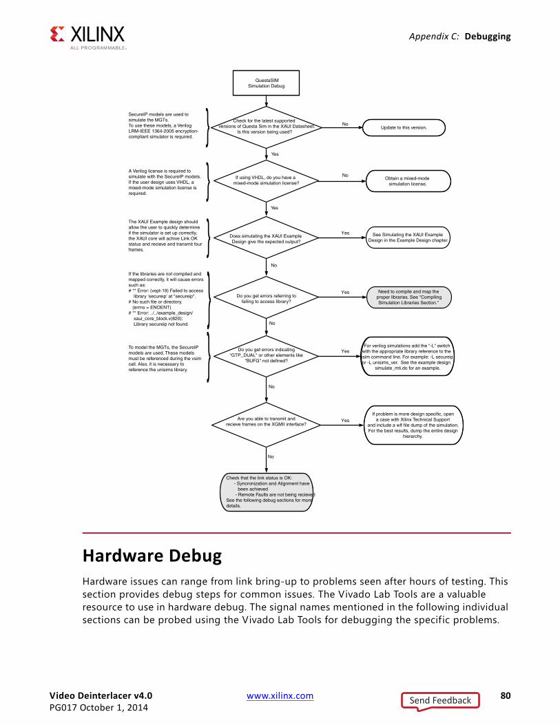
Video Deinterlacer v4.0 www.xilinx.com 80PG017 October 1, 2014
Appendix C: Debugging
Hardware DebugHardware issues can range from link bring-up to problems seen after hours of testing. This section provides debug steps for common issues. The Vivado Lab Tools are a valuable resource to use in hardware debug. The signal names mentioned in the following individual sections can be probed using the Vivado Lab Tools for debugging the specif ic problems.
X-Ref Target - Figure C-1
Send Feedback

Video Deinterlacer v4.0 www.xilinx.com 81PG017 October 1, 2014
Appendix C: Debugging
General ChecksEnsure that all the timing constraints for the core were properly incorporated from the example design and that all constraints were met during implementation.
• Does it work in post-place and route timing simulation? If problems are seen in hardware but not in timing simulation, this could indicate a PCB issue. Ensure that all clock sources are active and clean.
• If using MMCMs in the design, ensure that all MMCMs have obtained lock by monitoring the LOCKED port.
• If your outputs go to 0, check your licensing.
Evaluation Core TimeoutThe Deinterlacer hardware evaluation core times out after approximately eight hours of operation. The output is driven to zero. This results in a dark-green screen for YUV color systems
Interface Debug
AXI4-Lite InterfacesRead from a register that does not have all 0s as a default to verify that the interface is functional. Output s_axi_arready asserts when the read address is valid, and output s_axi_rvalid asserts when the read data/response is valid. If the interface is unresponsive, ensure that the following conditions are met:
• The S_AXI_ACLK and ACLK inputs are connected and toggling.
• The interface is not being held in reset, and S_AXI_ARESET is an active-Low reset.
• The interface is enabled, and s_axi_aclken is active-High (if used).
• The main core clocks are toggling and that the enables are also asserted.
• If the simulation has been run, verify in simulation and/or a Vivado Lab Tools debugging tool capture that the waveform is correct for accessing the AXI4-Lite interface.
AXI4-Stream InterfacesIf data is not being transmitted or received, check the following conditions:
• If transmit <interface_name>_tready is stuck low following the <interface_name>_tvalid input being asserted, the core cannot send data.
Send Feedback

Video Deinterlacer v4.0 www.xilinx.com 82PG017 October 1, 2014
Appendix C: Debugging
• If the receive <interface_name>_tvalid is stuck low, the core is not receiving data.
• Check that the ACLK inputs are connected and toggling.
• Check core configuration.
• Add appropriate core specif ic checks.
Debugging the Video Deinterlacer Core
Step 1: Video Pass Through Bring UpWhen initially bringing up the Deinterlacer in a simulator or FPGA environment, the Deinterlacer can be configured to use minimal external interfaces.
RECOMMENDED: Use of the interrupt mechanism is strongly advised, as this gives a real time indication of possible system issues.
After the system resets, the Deinterlacer starts in bypass mode. This mode requires no external memory interface for the Deinterlacer to move video through itself. It does require that the input and output video streams are operational.
By using the interrupt mechanism, you can determine if the system is stable with no error interrupts occurring. At this point, video should pass through the Deinterlacer data path in its native format, with all blanking removed. System designers should observe the video output matches the video input.
If error interrupts occur, it is likely that either the input or output FIFOs have over run. This occurs only when ports are enabled. For AXI4-Streaming interfaces, the Deinterlacer pauses until data can be moved through the Deinterlacer.
• Input FIFO overrun occurs if the output FIFO is stalled for too long, or the vid_clk is not running fast enough.
• Output FIFO overrun occurs if the output FIFO is stalled for too long (>1000 clks)
Step 2: Basic DeinterlacingYou should configure the Deinterlacer registers for the correct video raster size, basic "f ield interpolation mode", and then schedule the Deinterlacer to start on the next frame. At the next frame boundary, the Deinterlacer becomes synchronized. This can be seen at the top level pin "deint_sync" and also by an interrupt or reading the status register.
At this point, the Deinterlacer start to produce deinterlaced video output. The output video interface pixel rate will double. If a fault occurs, then the Deinterlacer either loses sync or generates a FIFO error. The reasons for this include:
Send Feedback

Video Deinterlacer v4.0 www.xilinx.com 83PG017 October 1, 2014
Appendix C: Debugging
• Loss of sync Due to automatic recovery from an internal FIFO overrun error, or the X/Y dimensions do not match the input video X/Y dimensions. The Deinterlacer must internal track X/Y so these registers must match.
• System errorIf this is the f irst time the error has been seen, then the likelihood is either that the vid_clk is not fast enough to allow pixel output at 2x the input rate, or the output FIFO has stalled the video and a backlog of less than 1000 pixels has occurred inside the Deinterlacer.
Step 3: Full Deinterlacing Using Memory ControllerAt this point, the Deinterlacer should be doing on-the-fly deinterlacing without the use of the AXI-MM port. Program the base addresses of the triple buffers to target a unique area of external memory. Update the mode register to select motion/full deinterlacing method. The Deinterlacer will on the next frame boundary start the memory interface port.
Under normal operation only the frame interrupt should ever trigger.
If a system error occurs, they can be broken down into 3 types:
• Write stream overflowThe AXI-Write port does not have enough bandwidth to keep up with the demand off the Deinterlacer. If possible and applicable, either increase the m_axi_aclk rate or in the case of AXI, increase the data width of this port.
• Read stream 0, Read stream 1 underflowEither of the two internal read data paths FIFO's have under run. This is generally due to excessive system latency, or to slow a m_axi_aclk rate.
Possible Vivado Lab Tools analysis using an AXI -Bus-Monitor would best help understand the bottleneck here.
Step 4: Check the Algorithms for Incorrect Video OutputBy using the built-in colourisation mode, the diagonal and motion kernel operations can be tracked. Turn on the colourisation modes and observe the output video. Using a known video test sequence the colourisation should show the motion artifacts and diagonal edge detections (only in moving objects). If the motion trails do not match the image then there is most likely data corruption in the external memory interface port. Although the transactions might be running cleanly, the triple buffers data would seem to be corrupt.
If corruption is visible, by activating PsF mode, the Deinterlacer is forced to use the external memory for every Deinterlaced video line. By enabling this mode, the user can validate the external memory is not corrupt.
Send Feedback

Video Deinterlacer v4.0 www.xilinx.com 84PG017 October 1, 2014
Appendix C: Debugging
Step 5: Pull-down Testing and PitfallsWhen applicable, the built-in cadence detectors can be individually enabled or disabled. Once enabled, the detectors periodically activate and deactivate. In images with low or no motion, the cadence detectors may disable until signif icant motion occurs again. This is normal operation. If you monitor the pulldown interrupts, you can see periodic cycling.
For instance, in the case of scene changes through black, the cadence detector may also drop out momentarily. As no motion is visible at this point, the quality of the video output will still be of highest quality even though the cadence detector is inactive.
Failure to detect a cadence in a known sequence that should have 3:2 or 2:2 is generally down to poor quality video that has undergone various compression's/re-authoring steps. For example in converting a DVD to SDI, the quality of the hardware decoders and subsequent scalers, color-space converters, chroma-resamplers, etc., can all introduce suff icient noise and artifacts that makes the cadence become undetectable. This is specially in the case of 2:2 footage, 3:2 encoding is a more robust mechanism.
Debugging for Bandwidth Issues This section is for debugging the loss of sync between the memory domain and the video domain of Deinterlacer.
When initially bringing up the Deinterlacer in a simulator or FPGA environment, the Deinterlacer can be configured to use minimal external interfaces.
RECOMMENDED: Turn off the Motion Engine to exclude the need for external memory interface for the Deinterlacer.
Enable the Interrupt control by setting the register upper bits 11, 10 and 9 to high for error detection on AXI-MM port (refer Interrupt Control (0x0008) Register in Chapter 2).
By removing the Motion Engine, you can make sure that the video passes through and basic Deinterlacing is working and refer to Step 1: Video Pass Through Bring Up and Step 2: Basic Deinterlacing if any errors occur in between the process. Make sure the upper bits 11, 10 and 9 are always set to Low (Interrupt Status (0x000C) Register in Chapter 2). By doing this, you can eliminates the external variable that not origin from memory controller and it also serves as a good indicator that they have bandwidth problem or memory interface problem for full Deinterlacing using memory controller process.
At this point, you should enable the Motion Engine so that the Deinterlacer does on-the-fly deinterlacing with the use of memory controller. The Interrupt status register is a good indicator for f inding the causes of the loss-of-sync. The upper IRQ bits 11, 10 and 9 lists the reason, typically either base software configuration or insuff icient memory bandwidth.
Send Feedback

Video Deinterlacer v4.0 www.xilinx.com 85PG017 October 1, 2014
Appendix C: Debugging
Below are two scenarios that can used to explain the reason out of sync happen during deinterlacing.
THE MCB is running DDR2 RAM at 400 MHz 16-bits and theoretically it can deliver 800Mbytes per second. Assuming a 80% utilization of the DDR, you can infer 800 * 80% = 640Mbytes per second. This is not enough for the Deinterlacer to do a 1080i to 1080p conversion. For 10-bit video, the Deinterlacer requires 933 Mbytes per second bandwidth. The loss of sync comes from the Deinterlacer not being able to read/write enough data. This under run can be seen in the simulation due to the DDR memory device being saturated. To observe tis, you can probe the top-level MCB pins.
Consider a case where the main m_axi_aclk is running at 66 MHz, when the pixel clock is 74.25 MHz. This means the Deinterlacer cannot move pixels from the memory domain to the video domain fast enough. To avoid this, m_axi_aclk must be less than or equal to vid_clk .
The following solutions can be implemented for loss of sync issue.
• Increasing the memory speed to 533 Mbits/S DDR2. (This requires simulation due to the high eff iciency from DDR.)
• Using DDR3.
• Removing the Motion Engine from the Deinterlacer and do “basic deinterlacing”. This requires No DDR at all, but produces a lower quality image.
Send Feedback

Video Deinterlacer v4.0 www.xilinx.com 86PG017 October 1, 2014
Appendix D
Additional Resources and Legal Notices
Xilinx ResourcesFor support resources such as Answers, Documentation, Downloads, and Forums, see Xilinx Support.
http://For a glossary of technical terms used in Xilinx documentation, see the Xilinx Glossary.
http://www.xilinx.com/support/documentation/sw_manuals/glossary.pdf.
For a comprehensive listing of Video and Imaging application notes, white papers, reference designs and related IP cores, see the Video and Imaging Resources page at:
http://www.xilinx.com/esp/video/refdes_listing.htm#ref_des.
ReferencesThese documents provide supplemental material useful with this user guide:
1. AXI Interconnect IP Data Sheet (DS768)
2. Vivado AXI Reference Guide (UG1037)
3. ISE to Vivado Design Suite Migration Guide (UG911)
4. Vivado Design Suite User Guide: Designing with IP (UG896)
5. Vivado Design Suite User Guide: Programming and Debugging (UG908)
6. Vivado Design Suite User Guide: Getting Started (UG910)
7. Vivado Design Suite User Guide: Logic Simulation (UG900)
8. Vivado Design Suite User Guide: Designing IP Subsystems Using IP Integrator (UG994)
9. Xilinx Real-Time Video Engine Targeted Reference Design
10. Xilinx Video and Image Processing Pack
Send Feedback

Video Deinterlacer v4.0 www.xilinx.com 87PG017 October 1, 2014
Appendix D: Additional Resources and Legal Notices
Revision HistoryThe following table shows the revision history for this document.
Please Read: Important Legal NoticesThe information disclosed to you hereunder (the "Materials") is provided solely for the selection and use of Xilinx products. To the maximum extent permitted by applicable law: (1) Materials are made available "AS IS" and with all faults, Xilinx hereby DISCLAIMS ALL WARRANTIES AND CONDITIONS, EXPRESS, IMPLIED, OR STATUTORY, INCLUDING BUT NOT LIMITED TO WARRANTIES OF MERCHANTABILITY, NON-INFRINGEMENT, OR FITNESS FOR ANY PARTICULAR PURPOSE; and (2) Xilinx shall not be liable (whether in contract or tort, including negligence, or under any other theory of liability) for any loss or damage of any kind or nature related to, arising under, or in connection with, the Materials (including your use of the Materials), including for any direct, indirect, special, incidental, or consequential loss or damage (including loss of data, profits, goodwill, or any type of loss or damage suffered as a result of any action brought by a third party) even if such damage or loss was reasonably foreseeable or Xilinx had been advised of the possibility of the same. Xilinx assumes no obligation to correct any errors contained in the Materials or to notify you of updates to the Materials or to product specifications. You may not reproduce, modify, distribute, or publicly display the Materials without prior written consent. Certain products are subject to the terms and conditions of Xilinx's limited warranty, please refer to Xilinx's Terms of Sale which can be viewed at http://www.xilinx.com/legal.htm#tos; IP cores may be subject to warranty and support terms contained in a license issued to you by Xilinx. Xilinx products are not designed or intended to be fail-safe or for use in any application requiring fail-safe performance; you assume sole risk and liability for use of Xilinx products in such critical applications, please refer to Xilinx's Terms of Sale which can be viewed at http://www.xilinx.com/legal.htm#tos.© Copyright 2011-2014 Xilinx, Inc. Xilinx, the Xilinx logo, Artix, ISE, Kintex, Spartan, Virtex, Zynq, and other designated brands included herein are trademarks of Xilinx in the United States and other countries. All other trademarks are the property of their respective owners.
Date Version Revision10/01/2014 4.0 Removed Application Software Development appendix.
04/02/2014 4.0 Updated AXI-S signals.
10/02/2013 4.0 Synch document version with core version. Updated Register Space information to synch up with the core.
03/20/2013 3.0 Updated for core version. Removed ISE chapters. Updated Debugging appendix. Updated Example Design chapter.
10/16/2012 3.0 Updated for core version. Added Vivado section. Removed GPP.
04/24/2012 2.0 Updated for core version.
10/19/2011 1.0 Initial Xilinx release of the IP core.
Send Feedback