victron ccgx-supported active battery management system
TRANSCRIPT
Rozna ulica 20, 6230 Postojna, Slovenia e-mail: [email protected]; www.rec-bms.com
1
VICTRON CCGX-SUPPORTED ACTIVE BATTERY MANAGEMENT SYSTEM
REC ACTIVE BMS
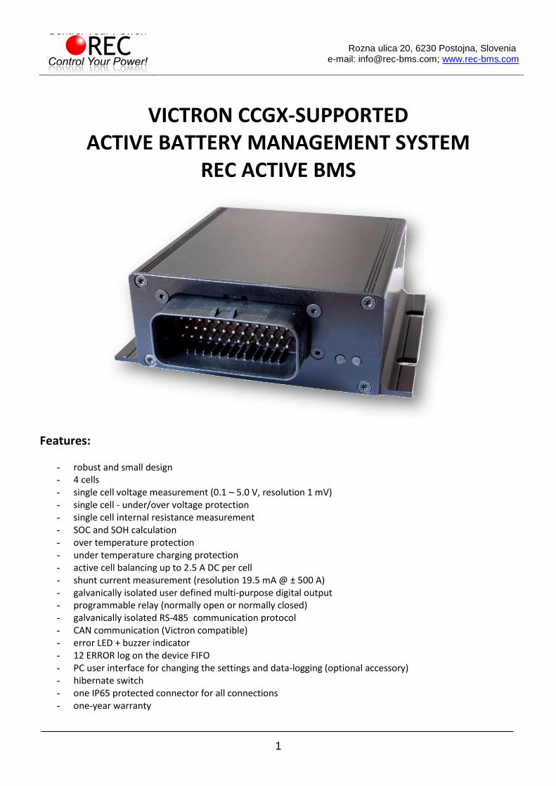
Features:
- robust and small design - 4 cells - single cell voltage measurement (0.1 – 5.0 V, resolution 1 mV) - single cell - under/over voltage protection - single cell internal resistance measurement - SOC and SOH calculation - over temperature protection - under temperature charging protection - active cell balancing up to 2.5 A DC per cell - shunt current measurement (resolution 19.5 mA @ ± 500 A) - galvanically isolated user defined multi-purpose digital output - programmable relay (normally open or normally closed) - galvanically isolated RS-485 communication protocol - CAN communication (Victron compatible) - error LED + buzzer indicator - 12 ERROR log on the device FIFO - PC user interface for changing the settings and data-logging (optional accessory) - hibernate switch - one IP65 protected connector for all connections - one-year warranty

BATTERY MANAGEMENT SYSTEM ABMS FOR VICTRON COLOR CONTROL GX
2 www.rec-bms.com
General Description of the BMS Unit: The Battery management system (BMS) monitors and controls each cell in the battery pack by measuring its parameters. The capacity of the battery pack differs from one cell to another and this increases with number of charging/discharging cycles. The Li-poly batteries are fully charged at typical cell voltage 4.16 - 4.20 V or 3.5 – 3.7 V for LiFePO4. Due to the different capacity this voltage is not reached at the same time for all cells in the pack. The lower the cell’s capacity the sooner this voltage is reached. When charging series connected cells with a single charger, voltage on some cells might be higher than the maximum allowed voltage. Overcharging the cell additionally lowers its capacity and number of charging cycles. The BMS equalizes cells’ voltage by diverting some of the charging current from higher voltage cells to the whole pack or from the whole pack to a lower voltage cells – active balancing. The device’s temperature is measured to protect the circuit from over-heating due to unexpected failure. Battery pack’s temperature is monitored by Dallas DS18B20 digital temperature sensor/s. Current is measured by a low-side shunt resistor. Battery pack current, temperature and cell’s voltage determine state of charge (SOC). State of health (SOH) is determined by comparing cell’s current parameters with the parameters of a new battery pack. The BMS default parameters are listed in Table 1.
Hardware Parameters: Table 1: ABMS hardware parameters.
Parameter Value Unit
BMS maximum pack voltage 16.8 V
BMS maximum cell voltage 5.0 V
Shunt common mode input voltage interval (Shunt+, Shunt -) to the Cell 1 negative
-0.3 to 3.0 V
Shunt sensor differential input voltage interval (Shunt+ to Shunt -) -0.25 to 0.25 V
max DC current relay @ 60 V DC 0.7 A
max AC current relay @ 230 V AC 2 A
max DC current @ optocoupler 15 mA
max DC voltage@ optocoupler 62.5 V
BMS unit disable power supply < 1 mW
BMS unit stand-by power supply < 60 mW
BMS unit cell balance fuse rating (SMD) 3 A
internal relay fuse 2 slow A
dimensions (w × l × h) 105 x 135 x 44 mm
IP protection IP65
Default Software Parameters: Table 2: Default BMS parameter settings.
Parameter Value Unit
chemistry 3 (LiFePO4) n.a.
capacity 400 Ah
balance start voltage 3.45 V
balance end voltage 3.58 V
maximum diverted current per cell up to 2.5 (5 pp) A
cell over-voltage switch-off 3.85 V
over-voltage switch-off hysteresis per cell 0.25 V
cell end of charge voltage 3.58 V
End of charge hysteresis per cell 0.25 V
SOC end of charge hysteresis 5 %
cell-under voltage protection switch-off 2.8 V

BATTERY MANAGEMENT SYSTEM ABMS FOR VICTRON COLOR CONTROL GX
3 www.rec-bms.com
under voltage protection switch-off hysteresis per cell 0.1 V
cell under voltage discharge protection 2.9 V
pack under voltage protection switch-off timer 4 s
cells max difference 0.25 V
BMS over-temperature switch-off 55 °C
BMS over-temperature switch-off hysteresis 5 °C
cell over temperature switch-off 55 °C
under temperature charging disable -15 °C
voltage to current coefficient 0.01171875 A/bit
current measurement zero offset 0.0 A
maximum charging/discharging current per inverter device 120/250 A
Number of inverter devices 1 n.a.
Charge coefficient 0.6 n.a.
Discharge coefficient 1.5 n.a.
relay 1 voltage level 3.58 V
relay 1 voltage level hysteresis -0.2 V
optocoupler 2 voltage level 2.9 V
optocoupler 2 voltage level hysteresis 0.2 V
CAN communication frequency 250 kbit/sec
System Overview:
Figure 1: System overview.

BATTERY MANAGEMENT SYSTEM ABMS FOR VICTRON COLOR CONTROL GX
4 www.rec-bms.com
BMS Unit Connections:
Figure 2: BMS unit front panel function overview.
Table 3: BMS unit male socket connections.
Connection Designator Description Cable Wiring
Label
1 relay 1 – user defined Normally closed
2 relay 1 – user defined Fused input RELAY CH F
3 Main relay Normally closed
4 Main relay Normally open RELAY DCH NO
5 Main relay Fused input RELAY DCH F
6 Hibernate switch signal -
7 Hibernate switch ground -
8 Cell 4 positive + Analog signal CELL 4+
9 Cell 3 positive + Analog signal CELL 3+
10 Cell 2 positive + Analog signal CELL 2+
11 Cell 1 positive + Analog signal CELL 1+
12 Cell 1 negative - Analog signal CELL 1-
13 relay 1 – user defined Normally open RELAY CH NO
14 Charge Optocoupler collector - OPTO CH C
15 Charge Optocoupler emitter (darlington + reverse
protection diode + polyfuse) - OPTO CH E
16 Optocoupler 2 – user defined collector - OPTO DCH C
17 Optocoupler 2 – user defined discharge emitter
(darlington + reverse protection diode + polyfuse) - OPTO DCH E
18 CAN Vcc 4.6 V output, max 10 mA CAN
19 CANL - CAN
20 RS485 Vcc - RS485
21 RS485 A - RS485
22 RS485 ground - RS485
23 RS485 B - RS485
24 Shunt- -
25 Shunt+ -
26 Shunt shield -
27 Dallas 18B20 temp. sensor GND + shield
28 Dallas 18B20 temp. sensor + 5 V
29 Dallas 18B20 temp. sensor 1-wire digital signal
30 CANH - CAN
31 CAN ground GND potential of the battery
pack CAN
32 - -
33 Address pin 3 Normally 0, connect to pin 35
to change to 1
34 Address pin 2 Normally 0, connect to pin 35
to change to 1
35 Address pin ground Fused ground for Address pins

BATTERY MANAGEMENT SYSTEM ABMS FOR VICTRON COLOR CONTROL GX
5 www.rec-bms.com
Setting the RS-485 Address: Address of the BMS unit is selected via the Address pins. Factory address is 2. Formula for changing the address is:
ActiveBMS 𝐴𝐷𝐷𝑅𝐸𝑆𝑆 = 22 ∗ 𝐴𝑑𝑑𝑟𝑒𝑠𝑠 𝑝𝑖𝑛 3̅̅ ̅̅ ̅̅ ̅̅ ̅̅ ̅̅ ̅̅ ̅̅ ̅̅ ̅ + 21 ∗ 𝐴𝑑𝑑𝑟𝑒𝑠𝑠 𝑝𝑖𝑛 2̅̅ ̅̅ ̅̅ ̅̅ ̅̅ ̅̅ ̅̅ ̅̅ ̅̅ ̅ + 20
! If multiple BMS units are used distinguished addresses should be set to avoid data collision on the RS-485 communication bus!
BMS Unit Connector: Before starting the assembly please go to website: http://www.te.com/catalog/pn/en/776164-1?RQPN=776164-1 …and read the connector assembly datasheet: AMPSEAL Automotive Plug Connector and Header Assembly in Application Specification and AMPSEAL Automotive Plug Assemblies 776268… in Instruction Sheet (U. S.).
BMS Unit Connector, Cells Part: Connect each cell to the BMS unit cell connector plug. Use silicon wires with cross section of 0.5 – 1.4 mm2 (20-16 AWG). ! Before inserting the connector check the voltage and polarity of each connection!
Figure 3: Battery pack connection plug – front side.
BMS Unit Power Supply: BMS unit is always supplied from the 4-th cell connection.

BATTERY MANAGEMENT SYSTEM ABMS FOR VICTRON COLOR CONTROL GX
6 www.rec-bms.com
BMS Unit Connection Instructions: Connect all necessary connections to the BMS connector first, check the polarities and then plug the female connector into the BMS. When the system components are plugged in, the enable switch can be turned ON and the unit starts the test procedure. Connection instruction video link: http://www.rec-bms.com/ABMS.html
When disconnecting the unit from the battery pack, the procedure should be followed in reverse order.
RS-485 Communication Protocol:
Figure 4: RS-485 DB9 connector front view.
Table 4: RS-485 DB9 connector pin designator.
pin designator 1 -
2 AGND
3 B
4 A
5 -
6 +5V to AGND
7 -
8 -
9 -
Galvanically isolated RS-485 (EN 61558-1, EN 61558-2) serves for logging and changing BMS parameters. Dedicated PC BMS Control Software or another RS-485 device may be used for the communication. Default RS-485 address is 2. Unlock password: Serial without the first minus e.g. 1A-XXXX. Messages are comprised as follows: STX, DA, SA, N, INSTRUCTION- 4 bytes, 16-bit CRC, ETX
STX start transmission <0x55> (always)
DA - destination address <0x01> to <0x10> (set as 6)
SA - sender address <0x00> (always 0)
N – number of sent bytes
INSTRUCTION 4 bytes for example.: 'L','C','D','1','?', - (combined from 4 ASCII characters, followed by ‘?’, if we would like to receive the current parameter value or ‘ ’,’xx.xx’ value in case we want to set a new value
16-bit CRC - big endian, for the whole message except STX in ETX - https://www.lammertbies.nl/comm/info/crc-calculation.html
ETX - end transmission <0xAA> (always)
Dataflow:
Bit rate: 56k
Data bits: 8
Stop bits: 1
Parity: None
Mode: Asynchronous
Little endian format when an array is sent

BATTERY MANAGEMENT SYSTEM ABMS FOR VICTRON COLOR CONTROL GX
7 www.rec-bms.com
Table 5: RS-485 instruction set.
INSTRUCTION DESCRIPTION BMS ANSWER SETTING INTERVAL
*IDN? Identification Answer “REC - BATTERY MANAGEMENT SYSTEM”
Read only
ARRAYS INSTRUCTIONS
LCD1? Main data
First answer is 28 – how many byte data will be sent and then data message follows as 7 float values: LCD1 [0] = min cell voltage, LCD1 [1] = max cell voltage, LCD1 [2] = current, LCD1 [3] = max temperature, LCD1 [4] = pack voltage, LCD1 [5] = SOC (state of charge) interval 0-1-> 1=100% and LCD1 [6] = SOH (state of health) interval 0-1-> 1=100%
Read only
LCD3? Main data
First answer is 8 – how many byte data will be sent and then data message follows as 8 byte values: LCD3 [0] = min cell BMS address, LCD3 [1] = min cell number, LCD3 [2] = max cell BMS address, LCD3 [3] = max cell number, LCD3 [4] = max temp. sens. BMS address, LCD3 [5] = max temp. sens. number, LCD3 [6] = Ah MSB, LCD3 [7] = Ah LSB
Read only
CELL? Cell voltages
BMS first responds with how many BMS units are connected, then it sends the values of the cells in float format
Read only
PTEM? Cell temperatures
BMS first responds with how many BMS units are connected then it sends the values of the temperature sensors in float format
Read only
RINT? Cells internal DC resistance BMS first responds with how many BMS units are connected then it sends the values in float format
Read only
BTEM? BMS temperature BMS first responds with value 1, then it sends the values of the BMS temperature sensor in float format
Read only
ERRO? Error number description array
First answer is 4 – how many byte data will be sent and then data message follows as 4 byte values: ERRO [0] = 0 – no error, 1 – error ERRO [1] = BMS unit ERRO [2] = error number (1-14) and ERRO [3] = number of the cell, temp. sensor where the error occurred
Read only
CELL SETTINGS INSTRUCTIONS
BVOL? or BVOL x.xx
Balance end voltage Returns float voltage [V] 2.5 to 4.30 V
BMIN? or BMIN x.xxx
Balancing start voltage Returns float voltage [V] 2.5 to 4.30 V
BATTERY MANAGEMENT SYSTEM ABMS FOR VICTRON COLOR CONTROL GX
8 www.rec-bms.com
CMAX? or CMAX x.xx
Cell over-voltage switch-off Returns float voltage [V] 2.0 to 4.30 V
MAXH? or MAXH x.xx
Over- voltage switch-off hysteresis per cell
Returns float voltage [V] 0.005 to 2.0 V
CMIN? or CMIN x.xxx
Cell-under voltage protection switch-off
Returns float voltage [V] 1.8 to 4.00 V
MINH? or MIN x.xxx
Over- voltage switch-off hysteresis per cell
Returns float voltage [V] 0.005 to 2.0 V
CHAR? Or CHAR x.xxx
Cell End of charging voltage Returns float voltage [V] 2.0 to 4.30 V
CHIS? Or CHIS x.xxx
End of charging voltage hysteresis per cell
Returns float voltage [V] 0.005 to 2.0 V
RAZL? or RAZL x.xx
Cells max difference Returns float voltage [V] 0.005 to 1.0 V
TEMPERATURE SETTINGS INSTRUCTIONS
TMAX? or TMAX x.xxx
cell over temperature switch-off
Returns float temperature [°C] -20 to 65 °C
TMIN? or TMIN x.xxx
Under-temperature charging disable
Returns float temperature [°C] -30 to 65 °C
TBAL? or TBAL x.xxx
BMS over-temperature switch-off
Returns float temperature [°C] -20 to 65 °C
BMTH? or BMTH x.xxx
BMS over temperature switch-off hysteresis
Returns float temperature [°C] 1 to 30 °C
CURRENT SETTINGS INSTRUCTIONS
IOFF? or IOFF x.xxx
Current measurement zero offset
Returns float current [A] -2.0 to 2.0 A
IOJA? Or IOJA x.xxx
Voltage to current coefficient Returns float value 0.0005 to 0.5
BATTERY PACK SETTINGS INSTRUCTIONS
CYCL? or CYCL xx
Number of full battery pack cycles
Returns integer value 0 to 8000
CAPA? or CAPA x.xxx
Battery pack capacity Returns float capacity [Ah] 1.0 to 3000.0 Ah
CHEM? or CHEM xx
Li-ion chemistry Returns unsigned char value 1 to 5
SOC SETTINGS INSTRUCTIONS
SOCH? or SOCH x.xxx
SOC end of charge hysteresis Returns float value 0 – 1.0 0.005 to 0.99
SOCS? or SOCS x.xx
SOC manual re-set Returns float value 0 – 1.0 0.01 to 1.00
VICTRON COMMUNICATION SETTINGS INSTRUCTIONS
CHAC? or CHAC x.xxx
Charge coefficient (0-3C) Returns float value 0-3.0 (default 0.6) 0.01 to 10.0
DCHC? or DCHC x.xxx
Discharge coefficient (0-3C) Returns float value 0-3.0 (default 1.5) 0.01 to 10.0
STRN? or STRN xx
Number of inverter devices on the bus
Returns unsigned char value (default 1)
1 to 6
MAXC? or MAXC x.xxx
Maximum charge current per inverter device
Returns float current [A] 5.0 to 280 A
MAXD? or MAXD x.xxx
Maximum discharge current per inverter device
Returns float current [A] 5.0 to 280 A
CLOW? or CLOW x.xxx
cell under-voltage discharge protection
Returns float voltage [V] 1.8 to 4.20 V
CANF? or CANF xx
CAN Frequency Returns unsigned integer value 100, 125, 200, 250, 500 or 1000
100, 125, 200, 250, 500 or 1000 kbit/s

BATTERY MANAGEMENT SYSTEM ABMS FOR VICTRON COLOR CONTROL GX
9 www.rec-bms.com
ERROR LOG INSTRUCTIONS
ERRL?
Returns error log data (FIFO register of the last 12 errors). By sending the same instruction the data pointer shifts from the last error entry to the first error entry, then it starts all over again
Returns “xx,zz; hh:mm:ss;dd.mm.yyyy” xx-error number zz-number of the cell/temp sensor
Read only
ERLD? or ERLD 1
Error log delete Returns unsigned char value. To reset Error log set ERLD to 1 and restart the ABMS.
0, 1
VMAX? or VMAX xx
Number of exceeded value of CMAX
Returns integer value 0 to 8000
VMIN? or VMIN xx
Number of exceeded value of CMIN
Returns integer value 0 to 8000
OUTPUTS SETTINGS INSTRUCTIONS
RE1L? or RE1L x.xxx
Relay 1 voltage level Returns float voltage [V] 1.8 to 4.30 V
RE1H? or RE1H x.xxx
Relay 1 voltage level hysteresis Returns float voltage [V] -2.0 to 2.0 V
OP2L? or OP2L x.xxx
Optocoupler 2 voltage level Returns float voltage [V] 1.8 to 4.30 V
OP2H? or OP2H x.xxx
Optocoupler 2 voltage level hysteresis
Returns float voltage [V] -2.0 to 2.0 V
ABMS SETTINGS INSTRUCTIONS
CAL1? or CAL1 x.xxx
Cell 1 calibration offset Returns float voltage [V] -0.025 to 0.025 V
CAL2? or CAL2 x.xxx
Cell 2 calibration offset Returns float voltage [V] -0.025 to 0.025 V
CAL3? or CAL3 x.xxx
Cell 3 calibration offset Returns float voltage [V] -0.025 to 0.025 V
CAL4? or CAL4 x.xxx
Cell 4 calibration offset Returns float voltage [V] -0.025 to 0.025 V
SERI? or SERI xx
ABMS Serial number Returns unsigned integer 0 - 9999 1-9999
SWVR? ABMS software version Returns string v.v-dd.mm.yyyy Read only
TIME? or TIME xx:xx:xx
ABMS RTC Time Returns/accepts “hh:mm:ss” format* -
DATE? or DATE xx.xx.xxxx
ABMS RTC DATE Returns/accepts “dd.mm.yyy” format*
-
WCIB? Which cell is being balanced Returns cell number Read only
*BMS->Time/Date pop-up window can be used to set both values at once.
Parameter accepted and changed value is responded with 'SET' answer. Example: proper byte message for 'LCD1?' instruction for BMS address 2 is: <0x55><0x02><0x00><0x05><0x4C><0x43><0x44><0x31><0x3F><0x53><0x90><0xAA> RS-485 message are executed when the microprocessor is not in interrupt routine so a timeout of 350 ms should be set for the answer to arrive. If the timeout occurs the message should be sent again. If an array of data is sent little endian is used for float or integer values. In case of single data is sent ASCII characters are used e.g. -1.2351e2 Custom made instructions can be added to the list to log or set the parameters that control the BMS algorithm or its outputs.

BATTERY MANAGEMENT SYSTEM ABMS FOR VICTRON COLOR CONTROL GX
10 www.rec-bms.com
CAN Communication:
Figure 5: CAN female DB9 connector front view. Table 6: CAN DB9 connector pin designator.
pin designator 1
2 CANL + TERMINATION
3 GND
4
5 -
6
7 CANH + TERMINATION
8 -
9 + 4.6V
Table 7: CAN RJ45 connector pin designator. Pin Designator
1 -
2 -
3 GND
4 -
5 -
6 -
7 CANH + TERMINATION*
8 CANL + TERMINATION* * Termination plug with 120 R
No termination is used inside ABMS connector. Terminate pins 2 and 7 with 120 Ohm resistor to prevent ABMS to reset. Additional RJ45 connector with 120 Ohms across CANL and CANH should be used for the end device on the CAN bus for end termination. 11-bit TX identifiers: 0x351, 0x355, 0x356, 0x35A, 0x35B, 0x35E, 0x370 11-bit RX heart-beat 0x305 message from CCGX is neglected.

BATTERY MANAGEMENT SYSTEM ABMS FOR VICTRON COLOR CONTROL GX
11 www.rec-bms.com
BMS Unit Start Procedure: When the BMS unit is turned ON it jumps into a boot-loader and checks if the user tries to upload a new firmware. Then it commences the test procedure by checking the balancing fuses and temperature sensors. After the test procedure red error LED turns off and the BMS unit starts working in normal mode. BMS Unit LED Indication: Power LED (green) is turned on in 2 s intervals, if the BMS is powered. When the battery pack is fully charged and SOC/end of charge hysteresis are set POWER LED is turn 100% on. Error LED (red) is turned on in case of system error and blinks number of error with 50 % duty cycle. Between error number 1 s timeout is introduced.
Cell Voltage Measurement: Cell voltages are measured every second. The cell measurement performs 4 ms cell measurement by Sigma Delta ADC. Each cell voltage is measured after the balancing fuse, in case the fuse blows, BMS signals error 10 to notify the user.
BMS Cell Balancing: Cells are balanced actively with very high efficiency in opposite to passive balancing, where all energy is lost in heat. Another benefit of active balancing is charging of dangerously low cell, if other cells are above dangerous level, consequently longer pack usage is possible.
Balancing START Voltage: If errors 2, 4, 5, 8, 10, 12 are not present and the highest cell voltage rises above Balance START voltage and current is > 0.2 A (charging stage) the BMS initiates balancing algorithm. A weighted cell voltage average is determined including cells DC internal resistance. Balancing algorithm calculates the voltage above which the cells are balanced. The lowest cell voltage is taken into account determining balancing voltage.
Balancing END Voltage: If errors 2, 4, 5, 8, 10, 12 are not present any cell is above balance END voltage are balanced regardless the battery pack current.
Cell Internal DC Resistance Measurement: Cell internal DC resistance is measured as a ratio of a voltage change and current change in two sequential measurement cycles. If the absolute current change is above 20 A, cells internal resistance is calculated. Moving average is used to filter out voltage spikes errors.
Battery Pack Temperature Measurement: Battery pack temperatures are measured by Dallas DS18B20 digital temperature sensor/s. Up to two sensors can be used in parallel. BMS should be turned off and main connector disconnected before adding sensors. If the temperature sensors wiring is placed near the power lines shielded cables should be used.

BATTERY MANAGEMENT SYSTEM ABMS FOR VICTRON COLOR CONTROL GX
12 www.rec-bms.com
BMS Current Measurement:
Low-side only precision shunt resistor for current measurement is used. A 4-wire Kelvin connection is used to measure voltage drop on the resistor. As short as possible shielded cable should be used to connect the power shunt and BMS. The battery pack current is measured every second. A high precision Sigma-Delta ADC is used to filter out the current spikes. The first current measurement is timed at the beginning of the cell measurement procedure for a proper internal DC resistance calculation. Two more 300 ms measurements are performed through the whole ABMS measurement interval Shunt connection is shown in Fig. 6.
Figure 6: Shunt resistor connection.
Voltage-to-current Coefficient: Different size and resistance shunts can be used, since the voltage-to-current coefficient can be changed in the BMS Control software as IOJA x.xxxx Current is calculated by the voltage drop at the shunt resistor. 1 LSB of the 18 bit ADC represents different current values according to the shunt resistance. The LSB coefficient can be calculated as:
𝑘𝐿𝑆𝐵 = 0.01171875 ∙0.05 V
300 A∙
𝐼currentx
𝑉dropx
where the Vdropx represents the voltage drop on shunt resistor at current Icurrentx.

BATTERY MANAGEMENT SYSTEM ABMS FOR VICTRON COLOR CONTROL GX
13 www.rec-bms.com
Battery Pack SOC Determination: SOC is determined by integrating the charge in or out of the battery pack. Different Li-ion chemistries may be selected: Table 8: Li-ion chemistry designators.
Number Type
1 Li-Po Kokam High power
2 Li-Po Kokam High capacity
3 Winston/Thunder-Sky/GWL LiFePO4
4 A123
5 Li-ion NMC/ LiMn2O4
Temperature and power correction coefficient are taken into consideration at the SOC calculation. Li-Po chemistry algorithms have an additional voltage to SOC regulation loop inside the algorithm. Actual cell capacity is recalculated by the number of the charging cycles as pointed out in the manufacturer’s datasheet. When BMS is connected to the battery pack for the first time, SOC is set to 50 %. SOC is reset to 100 % at the end of charging. Charging cycle is added if the coulomb counter had reached the battery pack’s capacity.
Battery Pack’s Charging Algorithm: The communication between the REC BMS and the Victron CCGX is established through the CAN bus. All the parameters that control the charging/discharging behavior are calculated by the ABMS and transmitted to the CCGX unit in every measurement cycle. The charging current is controlled by the Maximum charging current parameter. It’s calculated as Charge Coefficient CHAC x Battery capacity. The parameter has an upper limit which is defined as Maximum Charging current per device MAXC x number of inverter devices STRN. When the highest cell reaches the voltage interval between Balance start voltage and Balance end Voltage, the charging current starts to ramp down to 1.1 A x Number of Devices until the last cell rises to the End of Charge Voltage. At that point the Maximum charging voltage allowed is set to Number of cells x (End of Charge Voltage per cell – 0.5 x end of charge hysteresis per cell). End of Charge SOC hysteresis and End of charge cell voltage hysteresis are set to prevent unwanted switching. SOC is calibrated to 100 % and Power LED lights ON 100 % Charge optocoupler is turned off. Charging is stopped in case of systems errors (See System Errors indication chapter). SOC is calibrated to 96 % when the maximum open circuit cell voltage rises above the 0.502 x (Balance start voltage + balance end voltage), minimum open circuit voltage above balance start voltage and system is in charge regime.
Battery Pack’s Discharging Algorithm: Calculated maximum discharging current is sent to the Color Control GX by CAN communication in every measurement cycle. When the BMS starts/recovers from the error or from Discharging SOC hysteresis, maximum allowed discharging current is set. It is calculated as discharge coefficient DCHC x Battery capacity. If this value is higher than maximum discharging current per device MAXD x number of inverter devices STRN, maximum discharging current is decreased to this value. When the lowest cell voltage is discharged bellow the set threshold CLOW maximum discharging current starts to decrease down to 0.05 C (5 % of Capacity in A). After decreasing down, maximum allowed discharging current is set to 0 A. SOC is reset to 3 % and Discharging SOC hysteresis is set to 5 %. If the cell discharges bellow Minimum Cell voltage CMIN, ABMS signals Error 2 and SOC is reset to 0 %. If the Charger/inverter is connected to the grid maximum allowed discharge current is drawn from the grid. Otherwise 100 % load current is drawn from the battery until maximum allowed discharging current is set to 0 A.

BATTERY MANAGEMENT SYSTEM ABMS FOR VICTRON COLOR CONTROL GX
14 www.rec-bms.com
Victron System Configuration: Inverter/charger configuration Download and install VE Configuration tools from: https://www.victronenergy.com/support-and-downloads/software. Connect your computer to a VE.Bus product. MK3-USB interface and RJ45 UTP cable are required. Computer with internet connection will automatically download correct driver. Update all components to latest firmware, follow instructions on: https://www.victronenergy.com/live/updating_firmware:updating_ve.bus_products https://www.victronenergy.com/live/ccgx:firmware_updating Color Control settings: Update CCGX to 2.12 or higher. Connect Color Control GX (CCGX) with other devices (MPPT, Multis). Open Settings menu and select Services. Set CAN-bus profile to VE.Can & CAN-bus BMS (250kbit/s). Then in Settings menu select System setup. Change:
- Battery monitor to REC BMS in CAN-bus. - DVCC -> ON - SVS -> ON - STS -> ON - Limit charge control -> ON
CCGX settings are automatically saved when you change it. Grid set point is not fixed value and can be modified for user needs. IMPORTANT: Always keep CAN communication connected to BMS when resetting inverters and chargers. RECOMMENDED: In case of CAN communication failure, we recommended safety settings for under and over voltage protection. In computer program VE Configure under tab Inverter, set DC input low shut-down to battery pack’s voltage representing 15-20 % SOC (e.g. Li-ion; 3.4 V x 4 cells = 13.6 V) and DC input low restart to 50 % SOC (e.g. Li-ion; 3.7 V x 4 cells = 14.8V). DC input low restart should be higher than DC input low shut-down for @ least 1 V. Under tab Charger set Absorption voltage set it to 80 - 85 % SOC (e.g. Li-ion; 3.95 V x 4 cells = 15.8 V) and Float voltage 0.2V lower. Charge current can be default value. Additional safety can be added in program VE Configure under tab Assistants. Select Assistant “input current limit control (0142)”. Click start assistant, select Regulated the input current based on voltage on auxiliary input 1 or 2. Set input current limit to 0 A when voltage is higher than 2 V. Connect auxiliary input on Multi/Quattro to BMS I/O pins. Table 9: ABMS Victron AUX connection.
Multi/Quattro ABMS Opto charge
AUX + 1 (collector)
AUX - 2 (emitter)

BATTERY MANAGEMENT SYSTEM ABMS FOR VICTRON COLOR CONTROL GX
15 www.rec-bms.com
ABMS Outputs Settings: Non-Victron devices can be controlled by digital outputs Charge optocoupler and optocoupler 2 and relay 1. Charge optocoupler is already pre-programmed as charge sources control, while optocoupler 2 and relay 1 can be user programmed. Relay 1 hysteresis RE1H and oprocoupler 2 hysteresis OP2H play the role of top disconnect or bottom disconnect. If the hysteresis is set positive the output will bottom disconnect, while if negative it will top disconnect. Errors 4, 5, 8, 10, 11, 12 and 13 disconnect relay 1 and optocoupler 2. EXAMPLE 1: We want to use relay 1 as non-Victron charge control. Relay 1 should switch off if the highest cell reaches 3.65 V with 0.15 V hysteresis. In communicate window we set: RE1L 3.65 RE1H -0.15 EXAMPLE 2: We want to use optocoupler 2 as non-Victron charge control. Optocoupler 2 should switch off if the lowest cell drops under 2.70 V with 0.25 V hysteresis. In communicate window we set: OP2L 2.70 OP2H 0.25 Video instruction link for settings change: https://www.youtube.com/watch?v=sRr_5vBKupw

BATTERY MANAGEMENT SYSTEM ABMS FOR VICTRON COLOR CONTROL GX
16 www.rec-bms.com
Digital Outputs: Digital outputs are implemented with galvanic isolation. Optocouplers with diode reverse protection are used. When closed, a 0.7 V voltage drop over the digital output should be taken into account. Optocoupler outputs can drive a small signal relay or LED diodes. Fig. 7 shows two different connection schematics. Both outputs can be used to drive LED diodes for charge/discharge relay indication.
Figure 7: BMS digital outputs schematics.
Current limit resistor R can be calculated as:
𝑅 =𝑉CC2 − 0.7 𝑉 − 𝑉FVLED
𝐼LED
VFVLED represents LED forward voltage drop (typ. 1.9 – 2.3 V) while ILED represents LED current (2-5 mA).

BATTERY MANAGEMENT SYSTEM ABMS FOR VICTRON COLOR CONTROL GX
17 www.rec-bms.com
Pre-charge Connection: Battery pack main contactor is driven by ABMS internal main relay. In case of system with high input capacity (> 2,000 µF) a pre-charge system should be used to avoid high in-rush current spikes when the main contactor is turned on. High currents like this degrade the contactor, cells and input capacitors in the electronic devices. Fig. 8 shows contactor connection with the pre-charge unit. System voltage should be measured after the pre-charge without the connected contactor. System voltage should rise to > 70 % of the battery pack voltage. Otherwise longer pre-charge time should be used to ensure normal in-rush current.
Figure 8: Contactor connection schematics.
Parallel Cells Connection: Capacity can be increased by connecting multiple cells in parallel and then connect these sub-packs in series. Fig. 9 shows 2P4S connection with 2 cells in parallel and 4 pack like this in series. For proper current distribution 2 connection bars should be used between each 2P to 2P sub-pack.
Figure 9: 2P4S battery pack connection.

BATTERY MANAGEMENT SYSTEM ABMS FOR VICTRON COLOR CONTROL GX
18 www.rec-bms.com
System Error Indication: System errors are indicated with red error LED by the number of ON blinks, followed by a longer OFF state. Table 7: BMS error states.
Number of ON blinks
ERROR BMS OWNER
1
Single or multiple cell voltage is too high (cell over voltage switch-off).
BMS will try to balance down the problematic cell/cells to safe voltage level (5 s error hysteresis + single cell voltage hysteresis is applied). Charging is disabled, discharging is enabled. Main relay is disconnected. Relay 1 and optocoupler 2 are enabled.
Wait until the BMS does its job.
2
Single or multiple cell voltage is too low (cell under voltage protection switch-off).
BMS will try to charge the battery (5 s error hysteresis + single cell voltage hysteresis is applied). Charging is enabled, discharging is disabled. Main relay is disconnected. Relay 1 and optocoupler 2 are enabled.
Plug in the charging sources.
3 Cell voltages differs more than set.
BMS will try to balance the cells if balancing is enabled (5 s error hysteresis + 20 mV voltage difference hysteresis). Charging is enabled, discharging is enabled. Main relay is connected. Relay 1 and optocoupler 2 are enabled.
Wait until the BMS does its job. If the BMS is not able to balance the difference in a few hours, contact the service.
4
Cell temperature is too high (over temperature switch-off).
Cells temperature or cell inter-connecting cable temperature in the battery pack is/are too high. (5 s error hysteresis 2°C hysteresis). Charging is disabled, discharging is disabled. Main relay is disconnected. Relay 1 and optocoupler 2 are disabled.
Wait until the pack cools down.
5
BMS temperature is too high –internal error (BMS over temperature switch-off).
Due to extensive cell balancing/hardware error the BMS temperature rose over the upper limit (5 s error hysteresis + 5 °C temperature hysteresis). Charging is disabled, discharging is disabled. Main relay is disconnected. Relay 1 and optocoupler 2 are disabled.
Wait until the BMS cools down.
6 Number of cells, address is not set properly.
Charging is disabled, discharging is disabled. Main relay is disconnected. Relay 1 and optocoupler 2 are disabled.
Set proper ABMS address

BATTERY MANAGEMENT SYSTEM ABMS FOR VICTRON COLOR CONTROL GX
19 www.rec-bms.com
7
The temperature is too low for charging (under temperature charging disable).
If cells are charged at temperatures lower than operating temperature range, cells are aging much faster than they normally would, so charging is disabled (2 °C temperature hysteresis). Charging is disabled, discharging is enabled. Main relay is connected. Relay 1 and optocoupler 2 are enabled.
Wait until the battery’s temperature rises to usable range.
8 Temperature sensor error.
Temperature sensor is un-plugged or not working properly (5 s error hysteresis). Charging is disabled, discharging is disabled. Main relay is disconnected. Relay 1 and optocoupler 2 are disabled.
Turn-off BMS unit and try to re-plug the temp. sensor. If the BMS still signals error 8, contact the service. The temperature sensors should be replaced.
9 Communication error.
RS-485 Master-Slave communication only.
10 Cell in short circuit or BMS measurement error.
Single or multiple cell voltage is close to zero or out of range, indicating a blown fuse, short circuit or measuring failure (15 s error hysteresis + 10 mV voltage difference hysteresis). Charging is disabled, discharging is disabled. Main relay is disconnected. Relay 1 and optocoupler 2 are disabled.
Turn-off the BMS and check the cells connection to the BMS and fuses. Restart the BMS.
If the same error starts to signal again contact the service.
11 Main relay is in short circuit.
If the main relay should be opened and current is not zero or positive, the BMS signals error 11. Charging is disabled, discharging is disabled. Main relay is disconnected. Relay 1 and optocoupler 2 are disabled.
Restart the BMS unit. If the same error starts to signal again contact the service.
12 Error measuring current.
Current sensor is disconnected or not working properly. Charging is disabled, discharging is disabled. Main relay is disconnected. Relay 1 and optocoupler 2 are disabled.
Turn-off the BMS and check the sensor connections, re-plug the current sensor connector. Turn BMS back ON. If the BMS still signals error 12, contact the service.
13 Wrong cell chemistry selected.
In some application the chemistry pre-set is compulsory (5 s error hysteresis). Charging is disabled, discharging is disabled. Relay 1 and optocoupler 2 are disabled.
Use PC Control Software to set proper cell chemistry.

BATTERY MANAGEMENT SYSTEM ABMS FOR VICTRON COLOR CONTROL GX
20 www.rec-bms.com
14 EEPROM data corruption
During start-up or shut-down EEPROM read/write was interrupted.
Use PC Control Software to set proper settings
15 ABMS CAN bus communication baud rate error
Set CAN baud rate is not correct.
Use PC Control Software to set proper settings. 100k, 125k, 200k, 250k, 500k or 1M may be set.
16 ABMS internal communication failure
I2C or SPI communication failure. Restart the BMS unit. If the same
error starts to signal again contact the service.
BATTERY MANAGEMENT SYSTEM ABMS FOR VICTRON COLOR CONTROL GX
21 www.rec-bms.com
BMS Unit Dimensions:
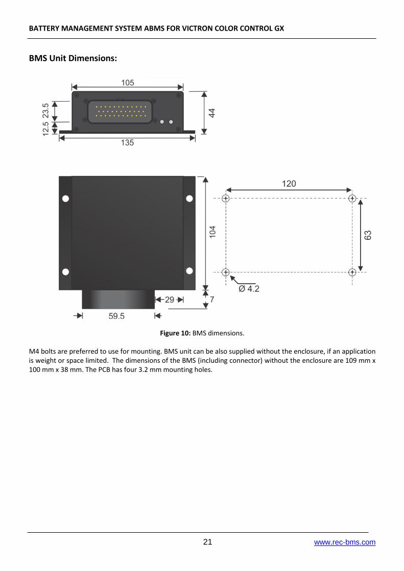
Figure 10: BMS dimensions.
M4 bolts are preferred to use for mounting. BMS unit can be also supplied without the enclosure, if an application is weight or space limited. The dimensions of the BMS (including connector) without the enclosure are 109 mm x 100 mm x 38 mm. The PCB has four 3.2 mm mounting holes.