victoreen 4000m+ - flukeassets.fluke.com/manuals/4000m___omeng0700.pdfvictoreen 4000m+ operators...
TRANSCRIPT

Victoreen 4000M+ X-Ray Test Device
Operators Manual May 2008 Manual No. 4000M+-1-1 Rev.7 ©2006, 2007, 2008 Fluke Corporation, All rights reserved. Printed in U.S.A. All product names are trademarks of their respective companies

Fluke Biomedical 6045 Cochran Road Cleveland, Ohio 44139 440.498.2564 www.flukebiomedical.com/
Table of Contents Section 1: General Information................................................................................... 1-1
1.1 Introduction .................................................................................................. 1-1 1.2 Specifications............................................................................................... 1-2 1.3 Getting Started............................................................................................. 1-3
Section 2: Operation.................................................................................................... 2-1 2.1 Power........................................................................................................... 2-1 2.2 Checking the Unit ........................................................................................ 2-1 2.3 Front Panel Configuration ............................................................................ 2-2 2.4 Rear Panel Configuration............................................................................. 2-5 2.5 Detector Positioning..................................................................................... 2-6 2.6 Calibration Check ........................................................................................ 2-7 2.7 Radiographic Measurements ....................................................................... 2-7 2.8 Fluoroscopic Measurements........................................................................ 2-9 2.9 Exposure/Rate Measurements .................................................................. 2-10
Section 3: Theory of Operation................................................................................... 3-1 3.1 Basic Definitions .......................................................................................... 3-1 3.2 Measurements Modes ................................................................................. 3-3 3.3 Filter Selection ............................................................................................. 3-3 3.4 Sensitivity Selection..................................................................................... 3-3 3.5 Detector Positioning..................................................................................... 3-4 3.6 Displayed Results ........................................................................................ 3-6
Appendix A: Detector Filter Graphs...............................................................................A-1 A.1 Detector Filter Graphs.................................................................................. A-1
Appendix B: Model 4000M+ Communication Protocol .................................................B-1 B.1 Data Formats ............................................................................................... B-1 B.2 Setting Up for Operation .............................................................................. B-1 B.3 The Commands ........................................................................................... B-1
Appendix C: Schematic Diagram and Replacement Parts ...........................................C-1 C.3 Schematic Diagram and Replacement Parts ...............................................C-1
Appendix D: kV Correction for Various Target/Filter Combinations ...........................D-1 D.1 kV Correction for Various Target/Filter Combinations..................................D-1
i

(Blank page)

General InformationIntroduction 1
1-1
Section 1 General Information
1.1 Introduction
The Model 4000M+ is a self-contained, noninvasive X-ray Test Device. In a single exposure, it simultaneously measures:
• kVp • Exposure or Air Kerma • Exposure Rate or Air Kerma Rate • Time
The Model 4000M+ features a dual sensitivity preamplifier for compatibility with Radiographic, Fluoroscopic, and Dental X-Ray Machines. In addition, it is calibrated for both tungsten anode (W/Al) and molybdenum (Mo/Mo) anode X-Ray tubes, making it suitable for screen film mammography applications. Its automatic waveform phase determination and extensive diagnostics minimize the potential for error.
The external ion chamber port accepts a variety of accessory ionization chambers for various applications, including mammography, photo-timer calibration, and input phosphor image intensifier measurements.
The Model 4000M+ uses proven technology to compute tube potential with +2% accuracy. Five separate, selectable filter pairs ensure optimum accuracy over the maximum range with minimum filtration dependence. A separate internal ionization chamber measures tube output. Time is measured with crystal quartz accuracy. A microprocessor controls the electronics and performs calculations to obtain the displayed results.
Victoreen 4000M+ Operators Manual
1-2
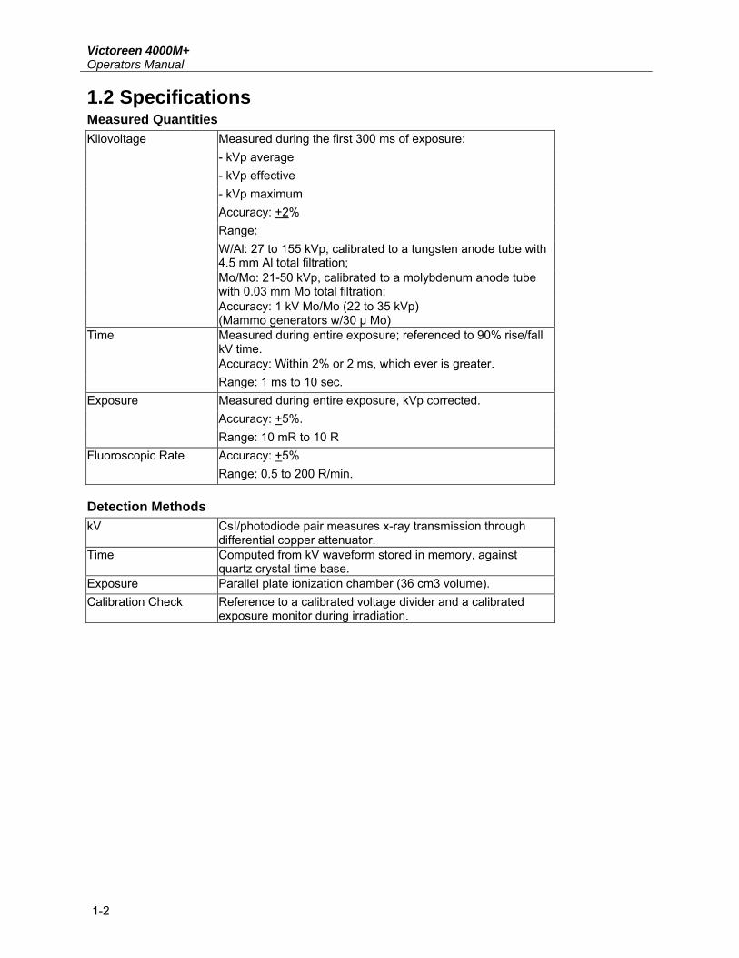
1.2 Specifications Measured Quantities
Measured during the first 300 ms of exposure: - kVp average - kVp effective - kVp maximum Accuracy: +2% Range: W/Al: 27 to 155 kVp, calibrated to a tungsten anode tube with 4.5 mm Al total filtration;
Kilovoltage
Mo/Mo: 21-50 kVp, calibrated to a molybdenum anode tube with 0.03 mm Mo total filtration;
Accuracy: 1 kV Mo/Mo (22 to 35 kVp) (Mammo generators w/30 µ Mo) Measured during entire exposure; referenced to 90% rise/fall kV time. Accuracy: Within 2% or 2 ms, which ever is greater.
Time
Range: 1 ms to 10 sec. Measured during entire exposure, kVp corrected. Accuracy: +5%.
Exposure
Range: 10 mR to 10 R Accuracy: +5% Fluoroscopic Rate Range: 0.5 to 200 R/min.
Detection Methods kV CsI/photodiode pair measures x-ray transmission through
differential copper attenuator. Time Computed from kV waveform stored in memory, against
quartz crystal time base. Exposure Parallel plate ionization chamber (36 cm3 volume). Calibration Check Reference to a calibrated voltage divider and a calibrated
exposure monitor during irradiation.
General InformationSpecifications 1
1-3
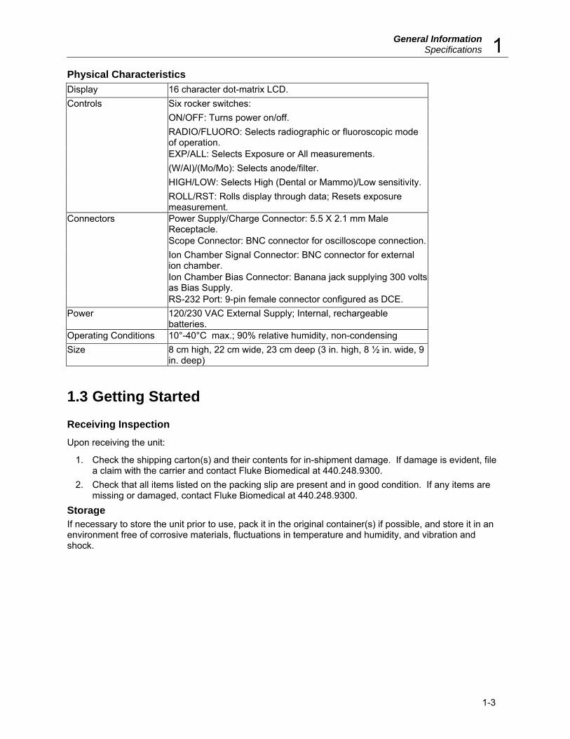
Physical Characteristics Display 16 character dot-matrix LCD.
Six rocker switches: ON/OFF: Turns power on/off. RADIO/FLUORO: Selects radiographic or fluoroscopic mode of operation. EXP/ALL: Selects Exposure or All measurements. (W/Al)/(Mo/Mo): Selects anode/filter. HIGH/LOW: Selects High (Dental or Mammo)/Low sensitivity.
Controls
ROLL/RST: Rolls display through data; Resets exposure measurement. Power Supply/Charge Connector: 5.5 X 2.1 mm Male Receptacle. Scope Connector: BNC connector for oscilloscope connection. Ion Chamber Signal Connector: BNC connector for external ion chamber. Ion Chamber Bias Connector: Banana jack supplying 300 volts as Bias Supply.
Connectors
RS-232 Port: 9-pin female connector configured as DCE. Power 120/230 VAC External Supply; Internal, rechargeable
batteries. Operating Conditions 10°-40°C max.; 90% relative humidity, non-condensing Size 8 cm high, 22 cm wide, 23 cm deep (3 in. high, 8 ½ in. wide, 9
in. deep)
1.3 Getting Started
Receiving Inspection
Upon receiving the unit:
1. Check the shipping carton(s) and their contents for in-shipment damage. If damage is evident, file a claim with the carrier and contact Fluke Biomedical at 440.248.9300.
2. Check that all items listed on the packing slip are present and in good condition. If any items are missing or damaged, contact Fluke Biomedical at 440.248.9300.
Storage If necessary to store the unit prior to use, pack it in the original container(s) if possible, and store it in an environment free of corrosive materials, fluctuations in temperature and humidity, and vibration and shock.

Victoreen 4000M+ Operators Manual
(Blank page)

2OperationPower
2-1
Section 2 Operation
2.1 Power
WARNING
Avoid shorting the battery. Do not mutilate or put a fire. Use only approved charging methods.
The Model 4000M+ can be powered by the internal rechargeable nickel cadmium batteries or by AC line power. An AC adapter is supplied with each unit. The connector for the adapter is located on the rear panel and labeled POWER (see Figure 2-2).
The batteries charge whenever the unit is plugged in to an AC source. The batteries will fully charge in approximately 6 hours, with the unit turned off, or in 24 hours, with the unit turned on. The batteries are protected from overcharging.
2.2 Checking the Unit Use the following procedure to check the Model 4000M+ for proper operation in the Radiographic Mode:
1. Place the unit on the x-ray table with the black plastic disk facing up. 2. Turn the Power Switch to ON. The Model No., software revision level, and filter setting will be
displayed, followed by a FLUORO Ready or RADIO Ready indication, depending on the position of the FLUORO/RADIO Switch.
3. Position the Mode Selection Switch to RADIO. 4. Position the EXP/ALL Switch to ALL. 5. Position the Tube Target (Anode)/Filter Selection Switch to W/Al. 6. Position the Sensitivity Selection Switch to LOW. 7. Rotate the filter wheel to the 70-120 kVp setting. The RADIO Ready indication should appear on
the display.
NOTE
If there is a hardware failure, an ERROR message may be displayed instead of the RADIO Ready condition. Error message indications and meanings are discussed in Section 3 – Theory of Operation.
8. Position the detector as discussed in Section 3 – Theory of Operation. 9. Make an exposure at 80 kVp and 100 mA and 100 mS. 10. Ready the display.
Victoreen 4000M+ Operators Manual
2-2
2.3 Front Panel Configuration
Model 4000M+
Noninvasive X-Ray Test Device
VICTOREEN
ROLL/RST HIGH
LOW
Mo/Mo
W/AI
EXP RADIO ON
ALL FLUORO OFF
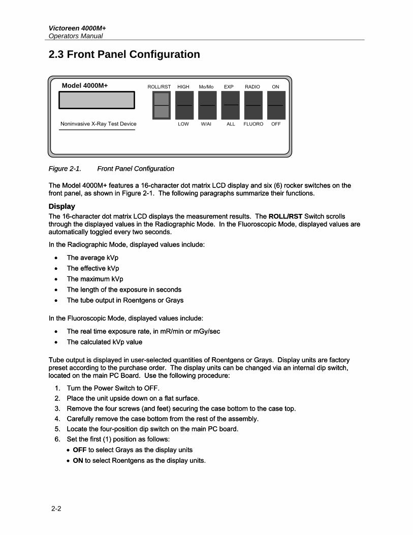
Figure 2-1. Front Panel Configuration Figure 2-1. Front Panel Configuration The Model 4000M+ features a 16-character dot matrix LCD display and six (6) rocker switches on the front panel, as shown in Figure 2-1. The following paragraphs summarize their functions. The Model 4000M+ features a 16-character dot matrix LCD display and six (6) rocker switches on the front panel, as shown in Figure 2-1. The following paragraphs summarize their functions.
Display Display The 16-character dot matrix LCD displays the measurement results. The ROLL/RST Switch scrolls through the displayed values in the Radiographic Mode. In the Fluoroscopic Mode, displayed values are automatically toggled every two seconds.
The 16-character dot matrix LCD displays the measurement results. The ROLL/RST Switch scrolls through the displayed values in the Radiographic Mode. In the Fluoroscopic Mode, displayed values are automatically toggled every two seconds.
In the Radiographic Mode, displayed values include: In the Radiographic Mode, displayed values include:
• The average kVp • The average kVp • The effective kVp • The effective kVp • The maximum kVp • The maximum kVp • The length of the exposure in seconds • The length of the exposure in seconds • The tube output in Roentgens or Grays • The tube output in Roentgens or Grays
In the Fluoroscopic Mode, displayed values include: In the Fluoroscopic Mode, displayed values include:
• The real time exposure rate, in mR/min or mGy/sec • The real time exposure rate, in mR/min or mGy/sec • The calculated kVp value • The calculated kVp value
Tube output is displayed in user-selected quantities of Roentgens or Grays. Display units are factory preset according to the purchase order. The display units can be changed via an internal dip switch, located on the main PC Board. Use the following procedure:
Tube output is displayed in user-selected quantities of Roentgens or Grays. Display units are factory preset according to the purchase order. The display units can be changed via an internal dip switch, located on the main PC Board. Use the following procedure:
1. Turn the Power Switch to OFF. 1. Turn the Power Switch to OFF. 2. Place the unit upside down on a flat surface. 2. Place the unit upside down on a flat surface. 3. Remove the four screws (and feet) securing the case bottom to the case top. 3. Remove the four screws (and feet) securing the case bottom to the case top. 4. Carefully remove the case bottom from the rest of the assembly. 4. Carefully remove the case bottom from the rest of the assembly. 5. Locate the four-position dip switch on the main PC board. 5. Locate the four-position dip switch on the main PC board. 6. Set the first (1) position as follows: 6. Set the first (1) position as follows:
• OFF to select Grays as the display units • OFF to select Grays as the display units • ON to select Roentgens as the display units. • ON to select Roentgens as the display units.

2OperationFront Panel Configuration
2-3
NOTE
Switch positions 2, 3, and 4 have been factory set and MUST NOT be changed.
7. Carefully replace the case top. 8. Secure the case top to the rest assembly using the screws (and feet) removed in Step 3.
ON/OFF Switch The ON/OFF Switch turns the instrument power on or off. As discussed earlier, the unit can be powered with either the internal rechargeable batteries or with AC line power using the supplied AC adapter.
NOTE
If an Invalid Filter message is displayed instead of the Filter Wheel setting, the Filter Wheel is set to CHK (or other illegal position) when the unit is turned ON in the RADIO or FLUORO modes.
If the RADIO/FLUORO Switch is set to RADIO, and the EXP/ALL Switch is set to ALL, a RADIO Ready message will be displayed.
If the RADIO/FLUORO Switch is set to FLUORO, and the EXP/ALL Switch is set to ALL, a FLUORO Ready message will be displayed followed by an exposure rate value (in mGy/sec or mR/min) and a calculated kVp value. The display will toggle between the exposure rate and kVp value.
NOTE The display will show exposure rate only (rather than toggle between the exposure rate and calculated kVp value) in the event that the input to the detector is too low to provide an adequate signal for a kVp calculation.
RADIO/FLUORO Switch The RADIO/FLUORO Switch selects either the Radiographic Measurement Mode or the Fluoroscopic Measurement Mode when the EXP/ALL Switch is set to ALL. When the EXP/ALL Switch is in EXP, the RADIO/FLUORO Switch selects either the DOSE or RATE mode. Refer to Section 3 – Theory of Operation for a discussion of applications for each mode.
NOTE
In the Fluoroscopic Mode, a real time display of tube output and kV are continuously updated. In the Radiographic Mode, data are accumulated until radiation ceases, and then the results are displayed.
EXP/ALL Switch The EXP/ALL Switch selects the Ion Chamber Mode, either the Exposure Dose/Rate Mode (EXP) or the Radiographic/FLUORO Measurement Mode (ALL).
(W/Al)/(Mo/Mo) Switch
Victoreen 4000M+ Operators Manual
2-4
The (W/Al)/(Mo/Mo) Switch selects the target/filter of the X-Ray machine being used. Refer to Section 3 – Theory of Operation for a discussion of the applications for each setting.
HIGH/LOW Switch The HIGH/LOW Switch selects the sensitivity of the detector. In the HIGH position, the kVp detector sensitivity is increased by a factor of 20, allowing compatibility with dental and mammography machines. The LOW position is suitable for most other applications.
NOTE
When the unit is in the Fluoroscopic Mode (FLUORO), the detector sensitivity is always high, regardless of the front panel HIGH/LOW Switch Setting.
ROLL/RST Switch The ROLL/RST Switch, active only in the Radiographic Measurement and Exposure Modes, is a momentary contact rocker that allows the user to change the display mode to Auto Roll or Manual Roll and to scroll through measured quantities. The ROLL/RST Switch also zeros the display in the Exposure Dose Mode. On power up (and whenever the Sensitivity, Measurement Mode, or filter wheel selection is changed) the display mode defaults to Auto Roll.
NOTE
In the Fluoroscopic Mode, the display automatically toggles between the measured quantities. Values are updated every two seconds.
In the Auto Roll Mode, the display scrolls through the measured quantities one after the other, as if the ROLL button were being pressed once every two seconds. The display will continue to scroll until the ROLL button is pressed again.
When a Radiographic exposure is complete, the kVp average value is displayed. Other measured quantities can be displayed, one after another, by pressing the ROLL Switch to scroll through them. Holding the ROLL Switch for longer than two seconds forces the display to enter the Auto Roll Mode.
Use the following procedure to change the Display Mode:
1. If the current Display Mode is Auto Roll (i.e., the display values are changing every two seconds) and the unit is in the Radiographic Measurement Mode: a. Press and release the ROLL Switch when the desired value is displayed (i.e., kVp Avg, kVp Eff,
kVp Max, Sec, or mR). The Display Mode will change to Manual Roll. The selected value will remain displayed until ROLL is pressed again.
b. Perform Step 2 to scroll through the measured quantities, one after another. 2. If the current Display Mode is Manual Roll, press and hold the ROLL Switch for approximately two
seconds. After “roll “ appears in the bottom right corner of the display, the Display Mode will change to Auto Roll. The display will be updated once every two seconds, scrolling through measured quantities one after the other.
When the ROLL/RST Switch is pressed to zero the exposure, the PLEASE WAIT message displays for approximately three seconds. The display will then read 0.0 mR or 0% Gy.

2OperationRear Panel Configuration
2-5
2.4 Rear Panel Configuration
Power Supply/Charge Connector The Power Supply/Charge Connector for the AC Adapter is located on the rear panel and labeled POWER (see Figure 2-2). An AC adapter is supplied with each unit. The AC adapter supplies 9 volts, 500 mA power to the unit and recharges the internal batteries.
CAUTION
Use only the AC Adapter Supplied with the unit; other adapters may damage the unit.
Scope Connector The Scope Connector is a BNC connector labeled SCOPE and located on the rear panel of the unit (see Figure 2-2). This connector allows the detector waveform to be displayed on a storage oscilloscope. It provides a voltage signal proportional to the radiation waveform as measured by the lightly filtered
detector.
BIAS SIGNALBEAM
DIRECTION
kVp RANGE
W/AISCOPE POWER
RS-232
Figure 2-2. Rear Panel Configuration Filter Wheel The filter wheel, located on the rear panel, allows selection of the kVp range. The wheel has six positions:
• 27-42 (W/AI) or 21-50 (Mo/Mo) • 35-60 • 50-85 • 70-120 • CHK • 100-155
The numeric labels refer to the kVp range. The range associated with the position selected should conform to the kVp setting of the X-ray machine. The CHK position is used for a calibration check.
Beam Direction Arrow The Beam Direction Arrow shows how the unit must be positioned to accept x-rays from the x-ray machine. For example, in the Fluoroscopic Mode, the unit must usually be turned upside down with the black plastic disk facing the x-ray tube.

Victoreen 4000M+ Operators Manual
2-6
NOTE
When the unit is upside down in the Fluoroscopic Mode, the display automatically inverts so it can be read from that position.
Ion Chamber Signal Connector The Ion Chamber Signal Connector, labeled SIGNAL, is a BNC connector that accepts the input and signal from the external ion chamber.
CAUTION
An electrical shock hazard exists on the ion chamber bias (HV). Extreme care should be taken when in close proximity to the ion chamber bias.
Ion Chamber Bias Connector The Ion Chamber Bias Connector, labeled BIAS, is a banana-type jack supplying 300 DC volts as bias supply for an external ion chamber.
RS-232 Port The RS-232 Port is a 9-pin female connector configured as Data Communications Equipment (DCE). See Appendix B for more information on this port.
2.5 Detector Positioning The detector must be positioned according to the type of measurement required. Section 3 – Theory of Operation includes a detailed discussion of detector positioning.
The following guidelines outline general detector positioning principles:
1. Locate the detector 46 to 102 centimeters (18 to 40 inches) away from the source of x-rays.
NOTEThe optimum source-to-detector distance (SDD) is 66 centimeters (26 inches) for most measurements. Refer to Appendix A for a discussion of source-to-detector distance.
2. The black plastic disk (on the top panel of the Model 4000M+) must point toward the source, and
must be in the approximate center of the beam. 3. The beam must be parallel to, and in the same direction as, the BEAM DIRECTION arrow printed
on the rear panel of the Model 4000M+. 4. To eliminate measurement error due to the ‘heel’ effect, position the Model 4000M+ so that the
front-to-rear panel axis is parallel to the tube axis.
2OperationCalibration Check
2-7
2.6 Calibration Check A calibration check should be performed periodically, or whenever a problem with the unit is suspected.
Use the following procedure to perform a calibration check on the Model 4000M+:
1. Turn the Power Switch to ON. The Model No., software revision level, and filter setting will be displayed, followed by a FLUORO Ready or RADIO Ready indication, depending on the position of the FLUORO/RADIO Switch.
2. Position the Mode Selection Switch to RADIO. 3. Position the Sensitivity Selection Switch to LOW. 4. Rotate the filter wheel to the CHK position. 5. Position the detector as discussed in Section 3 – Theory of Operation. 6. Set the x-ray machine to 100 kV, 100 mA, and 100 msec. 7. Make an exposure. 8. At the end of the exposure, one of the following messages will be displayed:
a. CHK OK, indicating that the Model 4000M+ has passed the calibration check. b. CHK Error LOW or CHK Error HIGH, indicating that the Model 4000M+ has NOT passed the
calibration check. Repeat Steps 2 through 6.
If the unit continues to fail the calibration test, contact Fluke Biomedical at 440.248.9300 for further instructions.
2.7 Radiographic Measurements Use the following procedure to make kVp, exposure, and time measurements with the Model 4000M+ in the Radiographic Mode:
1. Turn the Power Switch to ON. The Model No., software revision level, and filter setting will be displayed, followed by a FLUORO Ready or RADIO Ready indication, depending on the position of the FLUORO/RADIO Switch.
2. Position the Mode Selection Switch to RADIO. 3. Position the EXP/ALL Switch to ALL. 4. Position the Sensitivity Selection Switch to HIGH or LOW as required. (Refer to Sensitivity
Selection in Section 3 – Theory of Operation.) 5. Position the Tube Target (Anode)/Filter Selection Switch to Mo/Mo or W/Al as required. (Refer to
Tube Target (Anode)/Filter Selection in Section 3 – Theory of Operation.) 6. Rotate the filter wheel to the appropriate kVp setting, depending on the kVp setting of the X-Ray
machine. The RADIO Ready indication should appear on the display.
NOTE
If there is a hardware failure, an ERROR message may be displayed instead of the RADIO Ready condition. Error message indications and meanings are discussed in Section 3 – Theory of Operation.
7. Position the detector as discussed in Section 3 – Theory of Operation. 8. Make an exposure.

Victoreen 4000M+ Operators Manual
2-8
9. At the end of the exposure, the value selected when the display was placed in the Manual Roll Mode will be displayed. If the selected value is Average kVp, the following will be displayed:
XX.X kVp Avg 10. If the display is in Auto Roll Mode, the effective kVp maximum kVp, exposure time, and tube output
will be displayed in sequence. The display will continue to scroll through the values, changing once every two seconds, until either: a. Another exposure is made; when the exposure is complete, Analyzing... will be displayed.
Values for the new exposure will then be displayed, automatically changing once every two seconds.
b. The ROLL/RST button is pressed and held until roll is displayed in the lower right corner of the display. This puts the display in the Manual Roll Mode. Go to Step 11.
NOTE
The default display mode is Auto Roll; i.e., on power up, when the Measurement Mode Switch is changed from FLUORO to RADIO, the sensitivity selection (HIGH/LOW) is changed, or the filter wheel is repositioned, the display will automatically go into the Auto Roll Mode.
11. If the display is in the Manual Roll Mode:
a. Press ROLL/RST. Assuming, from Step 9, that the Average kVp value is displayed, pressing ROLL will display the effective kVp as:
XX.X kVp Eff b. Press ROLL/RST. The maximum kVp will be displayed as: XX.X kVp Max c. Press ROLL/RST. The exposure time will be displayed as: XX.XX Sec d. Press ROLL/RST. The tube output will be displayed as: XX.XX mR. e. Press ROLL/RST. The average kVp will be displayed as: XX.X kVp Avg f. Repeat Steps a through e as desired to scroll through the data. g. Press and hold the ROLL/RST button for longer than two seconds to place the display in the
Autoroll Mode. The display will continuously scroll through the measured quantities as if the ROLL/RST button were being pressed once every two seconds. Press ROLL/RST again to exit the Autoroll Mode.
12. Repeat Steps 3 through 11 as required. NOTE
The Model 4000M+ is auto resetting; therefore, another exposure can be made at any time. At the end of each exposure, Analyzing... will appear on the screen. The updated values will automatically be displayed in the previously selected display mode (Auto Roll or Manual Roll).

2OperationRadiographic Measurements
2-9
2.8 Fluoroscopic Measurements Use the following procedure to make fluoroscopic measurements with the Model 4000M+:
1. Turn the Power Switch to ON. The Model No., software revision level, and filter setting will be displayed, followed by a FLUORO Ready or RADIO Ready indication, depending on the position of the FLUORO/RADIO Switch.
2. Position the Mode Selection Switch to FLUORO.
NOTEAll fluoroscopic measurements are made using high sensitivity and W/Al target/filter; therefore, when the Mode Selection Switch is set to FLUORO, the target Filter Switch and the Sensitivity Selection Switch are inactive.
The filter setting will be displayed, followed by a FLUORO Ready indication. Two to four seconds after the FLUORO Ready indication, kVp and R/min (or mGy/sec) values will
be displayed in real time. The display will update and toggle between the kVp and R/min values very two seconds.
3. If necessary, rotate the filter wheel to the appropriate kVp range, depending on the kVp setting of the x-Ray machine. The filter wheel setting will be displayed followed by a FLUORO Ready indication and the real time kVp and R/min (or mGy/sec) values.
NOTE
If there is a hardware failure, an ERROR message may be displayed instead of the Ready condition. Refer to Section 3 – Theory of Operation for a discussion of Error indications.
4. Position the detector as discussed in Section 3 – Theory of Operation.
NOTE
When in the Fluoroscopic Mode, the display will invert when the unit is positioned upside down for reading under-table tubes.
NOTE
To eliminate measurement error due to the “heel” effect, position the Model 4000M+ so that the front-to-rear panel axis is parallel to the tube axis.
5. Start the exposure.
The display will update every two seconds; the displayed value will toggle between the real time R/min (or mGy/sec) value and a calculated kVp effective value.
NOTE
NOTE
Victoreen 4000M+ Operators Manual
2-10
If the exposure rate is insufficient to make a kVp measurement, only exposure rate will be displayed.
6. Stop the exposure when desired. Real time R/min (or mGy/sec) and kVp values will continue to be
displayed. 7. Repeat Steps 3 through 6 as required.
2.9 Exposure/Rate Measurements
NOTE
The following discussion focuses on Exposure and Exposure Rate measurements ONLY. The Air Kerma function is only applicable if the unit was ordered with the Air Kerma option.
Use the following to make an Exposure or Rate Measurement with the Model 4000M+:
1. With the power switch OFF, connect the external Ion Chamber, if desired. 2. Allow the unit to warm-up for five (5) minutes with the power switch ON and the EXP/ALL switch in
the ALL position. 3. Set the RADIO/FLUORO switch in either the RADIO position, to measure exposure, or the
FLUORO position, to measure rate. 4. Set the EXP/ALL switch in the EXP position. The message Please Wait will display for
approximately twenty (20) seconds while drift rate and offsets are measured. In the exposure mode, a threshold of 1 mR (10 µ Gy) must be reached before the exposure is displayed. The exposure or rate will therefore be displayed.
5. In the exposure mode, there is an AUTO RESET feature that retains the exposure reading on the display but resets the integrator at the end of an exposure. At the end of an exposure (when the exposure no longer increases) the display will blink twice, indicating that the AUTO RESET is taking place. The display may also be reset to zero (0) by pressing the ROLL/RST key.
NOTEWhen in the exposure mode, the exposure readings are corrected for offsets and drift rate. If the drift rate changes, a drift rate that is the difference between the old drift rate and the new drift rate will be present. Due to the AUTO RESET feature, this drift rate is not displayed. The effect of this drift will be observed if a significant amount of time elapses between readings.
There are three ways to eliminate this effect:
a. Discard the first exposure reading after a significant time has elapsed. b. Press the ROLL/RST key to re-zero the display. c. Switch the EXP/ALL switch to ALL, then back to EXP to repeat the offset and drift rate
measurement.

3Theory of OperationBasic Definitions
3-1
Section 3 Theory of Operation
3.1 Basic Definitions
Kilovoltage (kV)
NOTE
Kilovoltage is measured during the first 300 ms of the exposure.
During the x-ray exposure, the tube kilovoltage varies with time, producing the kV waveform. The size and shape of the waveform (including number of peaks in a given time period) depends on the design of the machine (e.g., single phase or 3-phase, full-wave or half-wave, etc.).
For example, in a 16-millisecond interval, on a single-phase, full-wave generator, there may be two peaks; whereas, on a 3-phase, full-wave generator, there may be six peaks in the same time period.
During data analysis, the peak values are calculated and stored in memory. These are instantaneous values and are waveform independent. Three kV values are displayed:
• kVp MAX • kVp AVG • kVp EFF
kVp MAXIMUM The displayed kVp MAX is the maximum peak value measured during the first 300 ms of the exposure. Since all of the peaks could be slightly different, the Model 4000M+ searches through the data and finds the peak with the highest value. This could be an overshoot or simply a minor variation in the peak value.
kVp AVERAGE The displayed kVp AVG is the average of all of the peaks. The Model 4000M+ determines this value by adding the values of all peaks and dividing by the number of peaks.
kVp EFFECTIVE The displayed kVp EFF value has the same physical meaning as the quantity measured by the kVp test cassette method; i.e., the two detector waveforms stored in memory are integrated independently (as film does), and then the kVp EFF is calculated from a ratio of the two sums.
Two sets of calibration coefficients exist, one for the calculation of single-phase effective kVp, the other for calculation of 3-phase (or constant potential) effective kVp. During the analysis, the phase of the x-ray machine is determined from the waveform, and the coefficients used to calibrate the kVp EFF are then automatically selected. Even with the calculation compensating for phase dependence, there is still some waveform dependence on this number.
Victoreen 4000M+ Operators Manual
3-2
Time The Model 4000M+ measures exposure time by determining the time between the first and last passage through 75% of kVp AVG. This is the technical definition used on most x-ray equipment, including 3-phase, medium-frequency and high-frequency generators.
On single-phase machines, time is defined as the number of radiation pulses that occur during the exposure, multiplied by the pulse period. This is equivalent to the time between the first and last passage through 0% of kVp AVG, i.e., timing on “zero crossing”. The difference in time between 0% and 75% is approximately 2 ms, which occurs before the first and after the last passage, making a total time difference of 4 ms. In order to resolve this timing definition discrepancy, it is recommended that four (4) milliseconds be added to the displayed time.
NOTE
The Model 4000M+ indicates single-phase x-ray machines by displaying a (�) with the time value (e.g., 35 msec �).
The Model 4000M+ measures exposure time from the internally stored waveform. The first 300 milliseconds and the last 20 ms of the hardened radiation waveform are stored along with the total exposure time determined from hardware “on” time (reference is crystal-controlled).
There will be circumstances when the x-ray timer is operating properly but the x-ray output time is incorrect. Due to this technique, occasional time measurement errors may be misdiagnosed. Consider the following examples:
1. Time Measurement Errors Due To Light Loading Exposures which result from a light load (e.g., 25 mA) on the generator may indicate a longer
exposure time (for the same time setting) on the Model 4000M+ than heavily loaded exposures. The difference is caused by the fact that more time is required at the end of the exposure for kV tube potential to discharge when low mA has been selected. As long as sufficient kV is on the tube, radiation is being emitted and, if it is above 75% of kVp AVG, the time will be measured by the Model 4000M+.
2. Time Measurement Errors On Machines Without Filament Pre-Heat If an x-ray machine filament pre-heat malfunctions, the output may be very low during the first part
of the exposure and then increase. Model 4000M+ time measurements may be significantly shorter than the time set on the machine. This is because the radiation, during first part of the exposure, may be below the level necessary to start the Model 4000M+ measuring time. This constitutes a machine malfunction discovered by the Model 4000M+ in which a timing error is caused by a pre-heat problem.
NOTE
Some x-ray machines, such as Dental x-ray machines, do not pre-heat the filament. If a time measurement error is seen on other x-ray machines, it may indicate a filament pre-heat malfunction.

3Theory of OperationBasic Definitions
3-3
Exposure and Exposure Rate The Model 4000M+ detector features an ion chamber directly over the diodes. Before an exposure is made, the Model 4000M+ measures and stores the offsets and drift rate associated with the ion chamber measurement. Every 300 ms during the radiographic exposure, the ion chamber integrator is read in order to test for full scale. If the integrator is greater than 40% of full scale, the reading is stored and the integrator is re-initialized without significant signal loss.
The sample time during the Fluoroscopic Mode is 1 second. After the exposure, the offset and drift rates are subtracted from the final ion chamber charge measurement, yielding the net charge accumulated during the exposure. This net measurement is then multiplied by an energy-compensated factor. The result is an exposure rate value.
Air Kerma and Air Kerma Rate ‘Kerma’ is an acronym for Kinetic Energy Released in the Medium. Air Kerma, then, is a measurement of the amount of photon energy transferred to atomic electrons in a unit mass of air. The displayed units are joules per kilogram of air, also referred to as Grays. Grays are computed by multiplying the exposure measurement (in Roentgens) by 0.00873 Gy/R.
NOTE
The Model 4000M+ is shipped with either an Exposure/Exposure Rate function or an Air Kerma/Air Kerma Rate function as specified on the purchase order. Display units may be changed as described in Section 2 – Operation.
3.2 Measurement Modes The Model 4000M+ has four Measurement Modes:
• Radiographic • Fluoroscopic • Exposure Only • Exposure Rate Only
In the Radiographic Measurement Mode, a single exposure is read. At the end of the exposure, measured quantities are displayed.
In the Fluoroscopic Measurement Mode, a continuous beam is analyzed and measured quantities are continuously displayed.
In the Exposure Dose Measurement Mode, the accumulated dose is displayed. It may be measured using the integral ion chamber or an optional external chamber.
In the Exposure Rate Measurement Mode, the exposure rate is displayed. It may be measured using the integral ion chamber or an optional external chamber.
3.3 Filter Selection The filter wheel position must correspond to the kVp setting on the x-ray machine being tested. Select the kVp range by rotating the filter wheel on the rear panel (see Figure 2-2).

Victoreen 4000M+ Operators Manual
3-4
3.4 Sensitivity Selection Sensitivity selection depends on the type of measurement required, as follows:
• Select HIGH sensitivity for dental, mammography, and other measurements requiring increased sensitivity. (Detector sensitivity is increased by a factor of 20.)
NOTE
When the unit is in the Fluoroscopic Mode (FLUORO), the detector sensitivity is always high, regardless of the front panel HIGH/LOW Switch setting.
• Select LOW sensitivity for standard radiographic measurements.
TUBE ANODE (TARGET)/FILTER SELECTION The tube anode (target)/filter selection depends on the X-Ray machine being tested:
• Select Mo/Mo for molybdenum anode mammography machines. • Select W/Al for standard radiographic machines.
NOTE
When using the 4000M+ with the Tube Anode (Target)/Filter Selection Switch set to Mo/Mo, set the filter wheel to the 21-50 kVp position.
3.5 Detector Positioning The proper detector positioning depends on the application as discussed in the following paragraphs.
Radiographic Measurements For a radiographic x-ray beam, position the detector as follows:
1. Position the detector on the x-ray table with the black plastic disk facing the x-ray tube.
NOTE
To eliminate measurement error due to the “heel” effect, position the Model 4000M+ so that the front-to-rear panel axis is parallel to the tube anode-to-cathode axis.
2. Position the x-ray tube with the tungsten target approximately 66 centimeters (26 inches) away
from the top of the black plastic disk.
NOTE
The optimum distance is 66 centimeters (26 inches) for most measurements. See Appendix A for a discussion of source-to-detector distance (SDD).

3Theory of OperationDetector Positioning
3-5
X-RAY TUBE
TUBE AXIS
MODEL 4000+ TOP PANEL
FRONT OR REAR PANEL FRONT OR REAR PANEL
Figure 3-1. Detector Positioning (Radiographic Measurements)
X-RAY TUBE
TUBE AXIS
MODEL 4000+ TOP PANEL
FRONT OR REAR PANEL FRONT OR REAR PANEL
Figure 3-2. Detector Positioning (Fluoroscopic Measurements)
3. Use the collimator light to collimate the beam to a rectangular area the same dimensions as the top of the detector box. The collimated beam should be approximately 22 square centimeters (8-1/2 by 9 inches).
4. Move the detector so that the black disk is centered in the collimated beam. Fluoroscopic Measurements In the Fluoroscopic Mode, the Model 4000M+ must usually be turned upside down. The black plastic disk must face the x-ray tube, which is normally located under the table.
NOTE
When the unit is upside down in the Fluoroscopic Mode, the Display automatically inverts so it can be read in that position.

Victoreen 4000M+ Operators Manual
3-6
1. Position the detector on the table with the black plastic disk facing down (toward the source of x-rays).
NOTE
To eliminate measurement error due to the “heel” effect, position the Model 4000M+ so that the front-to-rear panel axis is parallel to the tube anode-to-cathode axis.
NOTE
Align the BEAM DIRECTION arrow on detector’s rear panel with the direction of the x-ray beam.
2. Using centering marks provided on the table (or another centering method), center the detector
over the x-ray beam. 3. Energize the fluoroscope to view the detector on screen. 4. Move the fluoroscope so that the lead shield containing detector diodes (opaque rectangle) is
centered in the screen. 5. For automatic brightness control machines, place the appropriate shielding (e.g., a folded apron,
gloves, or a lead sheet) over the detector to drive the output to its maximum. For manual systems, set machine for maximum output and use the appropriate shielding to protect the image intensifier.
Other Applications Follow the same basic principles of detector positioning for other applications. In general:
1. Locate the detector 46 to 102 centimeters (18 to 40 inches) away from the source of x-rays.
NOTETo eliminate measurement error due to the “heel” effect, position the Model 4000M+ so that the front-to-rear panel axis is parallel to the tube anode-to-cathode axis.
2. Point the black plastic disk toward the source and in the approximate center of the beam. 3. For chest x-ray machines, the unit can be taped or strapped to the table in front of the film cassette.
3.6 Displayed Results As discussed in Section 2 – Operation:
• In the Radiographic Mode, displayed values include the average kVp, the effective kVp, the maximum kVp, length of the exposure in seconds, and the tube output in Roentgens or Grays.
• In the Fluoroscopic Mode, displayed values include the exposure rate (in mR/min or mGy/sec) and the calculated kVp value.
In addition to displayed values, the Model 4000M+ displays informational and error messages. Refer to Table 3-1 for a description of displayed messages.

Theory of OperationDisplayed Results 3
3-7
Table 3-1. Displayed Messages Message Description Model 4000M+ Unit Model No.; displayed at power ON. Revision X.XX Software Revision Level; displayed at power ON, after the Model No. Filter: XXX-XXX Filter wheel setting; displayed at power ON (after the Software Revision Level),
when the Measurement Mode Switch (RADIO/FLUORO) is toggled, and when the filter wheel is rotated.
FLUORO Ready The unit is in the Fluoroscopic Mode; no hardware errors have been diagnosed.
RADIO Ready The unit is in the Radiographic Mode; no hardware errors have been diagnosed. Calibration PROM CHECKSUM has failed; appears during Power Up Diagnostic Check.
Cal Prom Err
Corrective Action: Call Fluke Biomedical at 440.248.9300 for further instructions. Main PROM CHECKSUM has failed; appears during Power Up Diagnostic Check.
Main Prom Err
Corrective Action: Call Fluke Biomedical at 440.248.9300 for further instructions. RAM CHECK has failed; appears during Power Up Diagnostic Check. ******** Corrective Action: Call Fluke Biomedical at 440.248.9300 for further instructions.
Battery Low or Blank Battery voltage too low to operate unit properly. Display with no Light Corrective Action: Use the supplied AC Adapter until the batteries can be
recharged. Filter wheel is not in a valid position; displayed (if applicable) on power up or when entering a measurement mode.
Invalid Filter
Corrective Action: Rotate the filter wheel to the desired position. Measured offsets are not within acceptable limits; xx represents the errant channels as follows: 01 Ion Chamber 02 Channel A 03 Channel A and Ion Chamber 04 Channel B 05 Channel B and Ion Chamber 06 Channel A and Channel B 07 Channel A, Channel B, and Ion Chamber
Offset ERR xx
Corrective Action: Press ROLL to retry. If error persists, contact Fluke Biomedical at 440.248.9300 for further instructions.
Underrange (Radiographic Mode)
Signal level too low to provide accurate kVp (Radiographic Mode) measurement.
Corrective Action: Move filter to next lower position, if possible, decrease distance, increase mA, or switch to high sensitivity.
Overrange (Radiographic Mode)
Signal level too high to provide accurate kVp (Radiographic Mode) measurement.
Corrective Action: Move filter to next higher position, if possible, increase distance, decrease mA, or switch to low sensitivity.
HI* (Radiographic Mode)
kVp values have exceeded the filter wheel limits; appears (Radiographic Mode) at the extreme right of the display.

Victoreen 4000M+ Operators Manual
3-8
Corrective Action: For more accurate results, select the next higher filter wheel position and retry.
Message Description LO* (Radiographic Mode)
kVp values are lower than filter wheel limits; appears at (Radiographic Mode) the extreme right of the display.
Corrective Action: For more accurate results, select the next lower filter wheel position and retry.
OVERRANGE (Fluoroscopic Mode)
Signal level too high for kVp measurement.
Corrective Action: Select the next higher filter wheel position if possible, increase distance, or decrease mA.
HIGH (Fluoroscopic Mode)
kVp values have exceeded the filter wheel limits; appears (Fluoroscopic Mode) at the extreme right of the display.
Corrective Action: For more accurate results, select the next higher filter wheel position and retry.
LOW (Fluoroscopic Mode)
kVp values are below the limits of the filter wheel; (Fluoroscopic Mode) appears at the extreme right of the display.
Corrective Action: For more accurate results, select the next lower filter wheel position and retry.
CHK Error HI (CHK Radiographic Mode)
Model 4000M+ has failed the CHK test.
Corrective Action: Check detector and X-ray Machine settings and retry. CHK Error LO (CHK Radiographic Mode)
Model 4000M+ has failed the CHK test.
Corrective Action: Check detector and X-ray Machine settings and retry. CHK OK (CHK Radiographic Mode)
Model 4000M+ has passed the CHK test.
Filter wheel is not in a valid filter position for the Mo/Mo target. Use 21-50 Filter Corrective Action: Rotate the filter wheel to the 21-50 filter position. Value is too large to display. <over> Corrective Action: Check filter wheel position and sensitivity selection and retry.
* In general, slight out of range readings are acceptable. This is a warning message only. In addition, a LO error message may be encountered even though all kVps are within the selected filter range; the LO indication is displayed when any peak is below the range.
For example, at the 70-120 Filter Range, a HIGH error message may be displayed if the reading is 120.5. Obviously this reading is not very far out of range and so it may be considered a good reading.

AAppendixDetector Filter Graphs
A-1
Appendix A Detector Filter Graphs
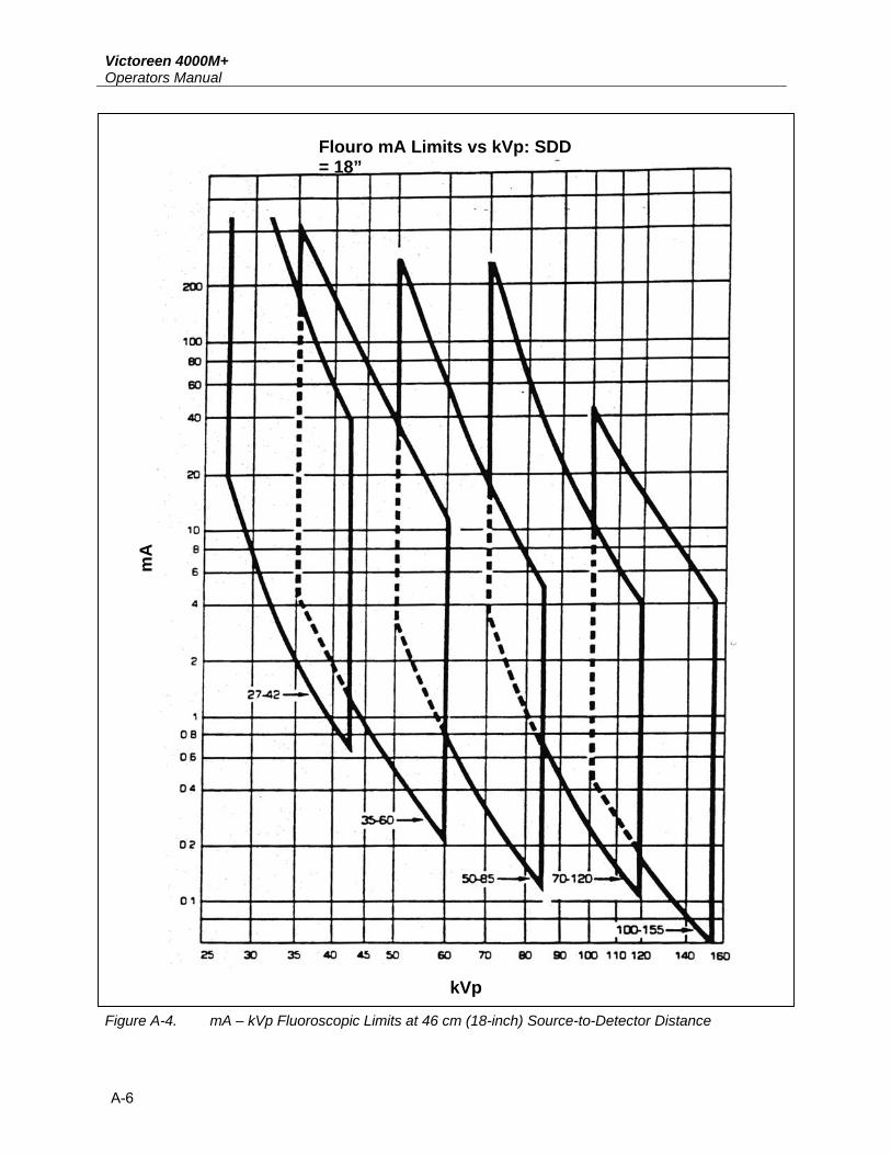
A.1 Detector Filter Graphs The curves in this Appendix can be used to determine allowed mA vs. kVp values for each filter position on the detector as follows:
1. Locate the kVp setting on the generator. 2. Read up the mA axis. The mA setting on the generator should fall within the lower and upper
curves for the filter range position. a. If the mA setting falls on or below the lower curve, the signal from the Model 4000M+ detector
may not be sufficient to cause data to be loaded. b. If the mA setting falls on or above the upper curve, the signal may overrange (OVER Error
message). NOTE
Each of the solid curves corresponds to a particular filter position as indicated in the Figure; dashed lines indicate areas of overlap between curves.
Keep in mind the following guidelines:
• The curves are valid for source-to-detector distances (SDD) of 46, 66, and 102 centimeters (18, 26, and 40 inches).
• If a distance not listed is used, correct the curve to determine the allowable mA values (mA1) using the inverse square law as follows: mA1 = mA0 x (SDD1/SDD2)2
where: SDD1 is the actual measurement distance, SDD2 is the distance represented by the curve, mA0 is the allowable mA for (SDD2), determined from the curve in the Figure.
For example, to use an SDD of 51 centimeters (20 inches) and a kVp of 80:
a. From Figure A-1, the graph for 46 centimeters (18 inches), it can be determined that the mA range is approximately 20 to 1500 mA for the 70 – 120 filter range.
b. Adjust from 46 to 51 centimeters (18 to 20 inches) by multiplying the mA limits by (20/18) <1.235 to yield a new mA range of 24.7 to 1852 mA. • The curves are derived from instantaneous dose rates and are equally valid on single-phase
and three-phase machines. • The curves are for instantaneous kV; if an extreme overshoot exists in the x-ray machine being
tested, the Model 4000M+ may display an OVER Error message under conditions that would normally be within limits.
• It is good measurement practice to use consistent parameters, although distance and field size are not critical to the measurement being made.

Victoreen 4000M+ Operators Manual
A-2
• An SDD of 66 centimeters (26 inches) should be used when possible. • Increasing the distance between the tube and detector decreases the signal to the
detector and may cause a loss of precision. • Decreasing the distance between the tube and detector increases the signal. • Increasing the field size does not have a direct effect on the kV measurement, but will
effect the exposure measurement because of increased scattering. • Beam uniformity may affect the overall accuracy of the measurement.

AAppendixDetector Filter Graphs
A-3
mA Limits vs. kVp: SDD = 18”
mA
kVp
Figure A-1. Ma – KvP limits at 46 cm (18-inch) Source-to-Detector Distance

Victoreen 4000M+ Operators Manual
A-4
mA Limits vs. kVp: SDD = 26”
mA
kVp
Figure A-2. mA – kVp Limits at 66 cm (26-inch) Source-to-Detector Distance

AAppendixDetector Filter Graphs
A-5
mA Limits vs. kVp: SDD = 40”
kVp
mA
Figure A-3. mA – kVp Limits at 102 cm (40-inch) Source-to-Detector Distance
Victoreen 4000M+ Operators Manual
A-6
Flouro mA Limits vs kVp: SDD = 18”
mA
kVp
Figure A-4. mA – kVp Fluoroscopic Limits at 46 cm (18-inch) Source-to-Detector Distance

AAppendixDetector Filter Graphs
A-7
Mammo mA Limits vs kVp: SDD = 16”
mA
kVp
Figure A-5. mA – kVp Mammographic Limits at 41 cm (16-inch) Source-to-Detector Distance (High Sensitivity)
Mammo mA Limits vs kVp: SDD = 16”
mA
kV
Figure A-6. mA – kVp Mammographic Limits at 41 cm (16-inch) Source-to-Detector Distance (Low Sensitivity)

Victoreen 4000M+ Operators Manual
(Blank page)
AppendixModel 4000M+ Communication Protocol B
B-1
Appendix B Model 4000M+ Communication Protocol
B.1 Data Formats All instructions to the 4000M+ are single-character ASCII commands. These commands should be invoked while the 4000M+ is in the READY condition. Note that the keyboard remains active throughout communication; therefore, pressing keys while the computer is communicating with the 4000M+ may cause problems.
Data transmissions from the 4000M+ are in the following formats:
1. Integer expressions are defined as any integer value between –32768 and +32767, inclusive. These will be sent via the RS-232 link as base 10 ASCII strings. No sign is sent for positive values; a minus sign is sent for negative values. Leading zeroes are suppressed.
2. Real numbers are defined as non-integer quantities and are sent in scientific notation. For example, the value, 80.34, is sent as an ASCII string as: +8.034E+01.
3. Field delimiters; numeric quantities are delimited by either the space (ASCII 20H) or the carriage return-line feed sequence (chr$(13);chr$(10)); allowing the numeric fields to be read by most high-level languages.
B.2 Setting up for Operation 1. If using a PC or PC compatible, connect the 4000M+ to the COM1 port using a straight RS-232 cable. 2. Initialize the port with the following BASIC statement:
10 OPEN “COM1:9600,N,8,1” AS #1
B.3 The Commands
Read Filter (F) The command to read the setting of the filter wheel is F. When the 4000M+ receives this character, it responds by sending an integer representing the filter setting (see Table B-1).
The integer sent will be delimited by a Carriage Return, Line feed (hereafter, represented as <CR><LF>).
The following is a sample program to read the filter wheel setting:
5 REM THESE INSTRUCTIONS READ FILTER SETTING. 10 0 INPUT #1, FILTER
Victoreen 4000M+ Operators Manual
B-2
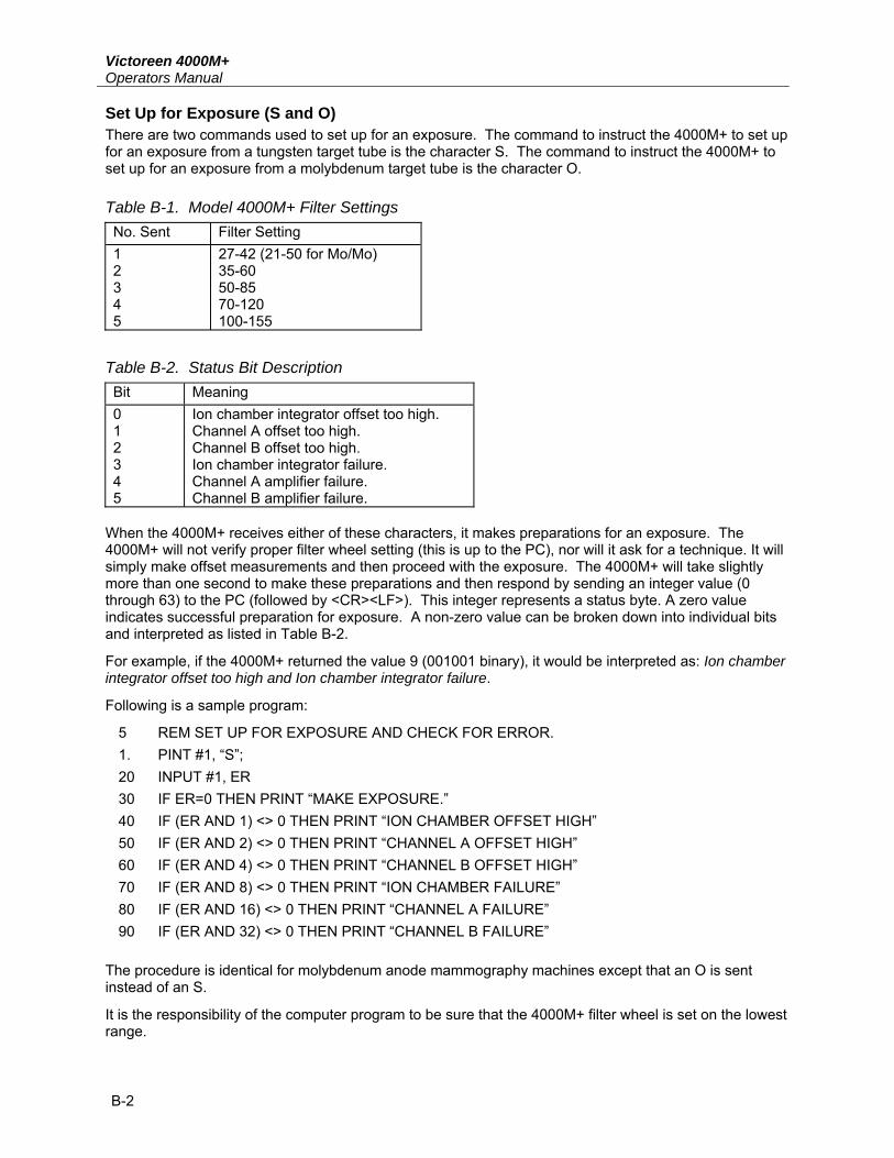
Set Up for Exposure (S and O) There are two commands used to set up for an exposure. The command to instruct the 4000M+ to set up for an exposure from a tungsten target tube is the character S. The command to instruct the 4000M+ to set up for an exposure from a molybdenum target tube is the character O.
Table B-1. Model 4000M+ Filter Settings No. Sent Filter Setting 1 2 3 4 5
27-42 (21-50 for Mo/Mo) 35-60 50-85 70-120 100-155
Table B-2. Status Bit Description Bit Meaning 0 1 2 3 4 5
Ion chamber integrator offset too high. Channel A offset too high. Channel B offset too high. Ion chamber integrator failure. Channel A amplifier failure. Channel B amplifier failure.
When the 4000M+ receives either of these characters, it makes preparations for an exposure. The 4000M+ will not verify proper filter wheel setting (this is up to the PC), nor will it ask for a technique. It will simply make offset measurements and then proceed with the exposure. The 4000M+ will take slightly more than one second to make these preparations and then respond by sending an integer value (0 through 63) to the PC (followed by <CR><LF>). This integer represents a status byte. A zero value indicates successful preparation for exposure. A non-zero value can be broken down into individual bits and interpreted as listed in Table B-2.
For example, if the 4000M+ returned the value 9 (001001 binary), it would be interpreted as: Ion chamber integrator offset too high and Ion chamber integrator failure.
Following is a sample program:
5 REM SET UP FOR EXPOSURE AND CHECK FOR ERROR. 1. PINT #1, “S”; 20 INPUT #1, ER 30 IF ER=0 THEN PRINT “MAKE EXPOSURE.” 40 IF (ER AND 1) <> 0 THEN PRINT “ION CHAMBER OFFSET HIGH” 50 IF (ER AND 2) <> 0 THEN PRINT “CHANNEL A OFFSET HIGH” 60 IF (ER AND 4) <> 0 THEN PRINT “CHANNEL B OFFSET HIGH” 70 IF (ER AND 8) <> 0 THEN PRINT “ION CHAMBER FAILURE” 80 IF (ER AND 16) <> 0 THEN PRINT “CHANNEL A FAILURE” 90 IF (ER AND 32) <> 0 THEN PRINT “CHANNEL B FAILURE”
The procedure is identical for molybdenum anode mammography machines except that an O is sent instead of an S.
It is the responsibility of the computer program to be sure that the 4000M+ filter wheel is set on the lowest range.

AppendixThe Commands B
B-3
Send Exposure Data (D) The command for sending data acquired by an exposure is the character, D. The 4000M+ will respond to this command by sending:
<KVEFF> <KVAVG> <MR> <TIME> <NP><CR><LF> where:
KVEFF is kV effective,
KVAVG is kV average,
MR is dose,
TIME is exposure time,
NP is number of kV peaks measured.
This transmission will then be followed immediately by:
<KVP1><KVP2>...<KVPN><CR><LF> where KVP1 through KVPN are kV peaks.
The following is a sample program:
5 REM THIS CODE READS THE EXPOSURE DATA. 10 PRINT #1, “D”; 20 INPUT #1,KVEFF,KVAVG,MR,SEC,NP FOR I=1 TO NP 40 INPUT #1, PEAK(I) 50 NEXT I 60 REM THE ARRAY, PEAK, CONTAINS KV PEAK VALUES, 70 ‘KVEFF, KVAVG, MR, AND SEC CONTAIN EFFECTIVE 80 ‘KILOVOLTAGE, AVERAGE KV, EXPOSURE, AND TIME, 90 ‘RESPECTIVELY.
Send Waveform (W) Both channel A and channel B radiation waveforms are available through the RS-232 port. The command is W. This puts the 4000M+ in the waveform send mode. To get 10 data points, send the 4000M+ an integer representing the number of the first data point; terminated with a <CR>. The 4000M+ will send 10 data points, beginning at the one requested, in the format:
<CHANNEL A> <CHANNEL B><CR><LF>. The next 10 points may then be requested by sending the index of the next point to be sent, followed by a <CR>. When all is finished, send <ESC> (chr$(27)).

Victoreen 4000M+ Operators Manual
B-4
The following is a sample program:
5 REM THIS PROGRAM READS THE FIRST HUNDRED DATA 6 ‘ POINTS INTO THE ARRAYS A AND B. 10 PINT #1, W; 20 FOR I=1 TO 100 STEP 10 30 PRINT #1, I 40 FOR J=I TO I+10 50 IPUT #1,A(I), B(I) 60 NEXT J 70 NEXT I 80 PRINT #1, CHR$(27);
Fluoroscopic Measurement (U) The 4000M+ may be used in the Fluoroscopic Mode while under control of a host computer. The procedure is as follows:
1. Send the character U to the 4000M+ via RS-232. 3. The 4000M+ responds with a status code; a zero (0) indicates all is ok; any other code indicates a
hardware error. 4. Once per second, thereafter, the 4000M+ sends one or two numbers, followed either by R or K and
then a carriage return/line feed. The numbers followed by R are exposure rate, in R/min. Those followed by K are kilo voltage
values. When there is little or no exposure, only the R values will be given. 5. This output will continue indefinitely. To stop it, repeatedly send the character X until the 4000M+
responds.
NOTE
The 4000M+ does not look at the RS-232 port while it is accumulating real-time data. Therefore, send the X repeatedly until 4000M+ responds.
6. The 4000M+ responds by repeatedly sending 3 <CR><LF> for a period of time, giving the computer
a chance to alternate between sending the X and looking for the response. 7. When the 3s are no longer being sent, the 4000M+ will have accumulated a final 100 ms of
waveform data. A final status code is sent. A code of 01 means all has gone well. A code of 50, 51, or 53 indicates low kVp, high kVp, or all data below radiation threshold, respectively.
8. The commands D or W may now be used to review the data. Set Detector Sensitivity (H or L) Set the detector sensitivity as follows:
1. Send the character H to the 4000M+ to set the sensitivity to high. 2. Send the character L to the 4000M+ to set the sensitivity to low.
The 4000M+ responds by echoing back the character sent and an 01 to indicate Ready.
BAppendixThe Commands
B-5
Set Pre-Acquisition Time Delay (E) The 4000M+ may be programmed for a pre-acquisition time delay via the RS-232 port. The default value for the delay is zero. Any other value, in milliseconds, will cause the 4000M+ to wait the allotted time after x-rays are detected, before accumulating data. The format for the command is:
Exxxx<CR> where xxxx is the number (decimal) of milliseconds to delay; xxxx may range from 0 to 65535.
Once a delay is set, it remains in 4000M+ memory and goes into effect for subsequent exposures, until changed.
Set Machine Phase (1 or 3) The 4000M+ calculates time differently depending on whether the x-ray machine is a single-phase machine or a three-phase machine. Three-phase time is measured between 75% of kV peak; single-phase time is measured between zero crossings. To tell 4000M+ the phase of the x-ray machine, simply send a 1 or a 3.
Send Slope and Offset Data I The command to send the slope and offset data is the character string Cn where n is an integer representing the filter wheel setting as listed in Table B-3. The 4000M+ responds by sending:
<SLOPE 1> <OFFSET 1><CR><LF> <SLOPE 2> <OFFSET 2><CR><LF>
where:
SLOPE 2 and OFFSET 2 are used to calculate the kVp eff for single phase waveforms taken with filter n, and
SLOPE 1 and OFFSET 1 are used to calculate all other kV values taken with filter n.
Send Part Number and Revision Level (V)
The command to send the part number and revision level is the character V. The 4000M+ responds by sending:
<PART><REVISION> <CR><LF> where:
PART is the part number, and
REVISION is the revision level.
Table B-3. Model 4000M+ Filter Wheel Setting Representation (Cn) n Filter Setting 1 27-42 2 35-60 3 50-85 4 70-120 5 100-155 6 21-50 (Mo/Mo)
NOTE

Victoreen 4000M+ Operators Manual
B-6
Calculation of kV Waveform The kV waveform may be reconstructed via calculations performed on the radiation waveforms. The pseudo code for producing all three available waveforms is as follows:
Use the D command to acquire a 4000M+ data dump. Use the F command to read the FILTER.
If TIME >100 ms, then
Set NPOINTS to 757, Else,
Set NPOINTS to Int(TIME(sec)/1.32E-4)). Use the W command to fill the two buffers, AWAV and BWAV with channel A and channel B data, respectively. The number of points acquired should be NPOINTS.
Use the C command to read the floating-point value, slope, and offset.
Set BMAX to 0.
For J = 1 to NPOINTS,
If BWAV(J) > BMAX, then BMAX = BWAV(J);
Set THRESHOLD to BMAX/16.
If THRESHOLD < 255, then
Set THRESHOLD to 255. Set LO to low limit for filter setting used.
Set HI to high limit for filter setting used.
Set LORAT to (In(0.9 * LO) – OFFSET1)/SLOPE.
Set HIRAT to (In(1.05 * HI) – OFFSET1)/SLOPE.
For I = 1 to NPOINTS,
If AWAV(I) <> 0.0 then, Set R to BWAV(I)/AWAV(I);
Else, Set to 0.0.
If R < LORAT or R > HIRAT or BWAV[I] < THRESHOLD, then Set KWAV(I) to 0.0; Else,
Set KWAV(I) to exp(R * SLOPE + OFFSET1). end.
At this point, there are three arrays, AWAV, BWAV and KWAV, representing the three available waveforms, lightly filtered, heavily filtered, and kV, respectively. Each array element corresponds to 132 microseconds of waveform.

AppendixSchematic Diagram and Replacement Parts C
C-1
Appendix C Schematic Diagram and Replacement Parts
C-1 Schematic Diagram and Replacement Parts The Model 4000M+ schematic diagram is provided, followed by the Bill of Materials.
Document No. Description
4000-100-10 Model 4000 Main Board
4000-100-10 Bill of Material, Model 4000 Assembly P.C.B.

Victoreen 4000M+ Operators Manual
(Blank page)

AppendixKV Correction for Various Target/Filter Combinations D
D-1
Appendix D kV Correction for Various Target/Filter Combinations
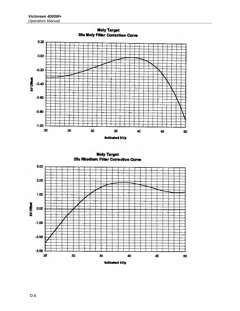
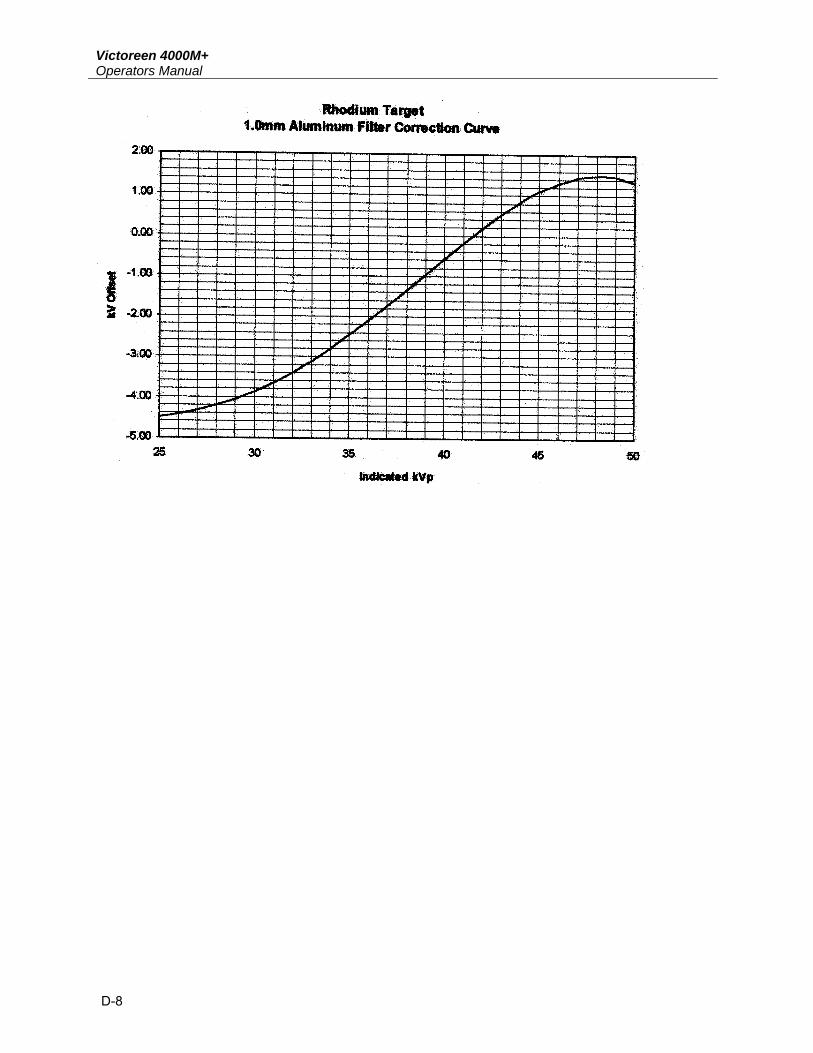
D-1 kV Correction for Various Target/Filter Combinations The following tables and graphs may be used to correct 4000M+ kVp readings taken with the following Mammographic x-ray tube target/filter combinations:
Molybdenum target 30µ Molybdenum filter Molybdenum target 25µ Rhodium filter Molybdenum target 1 mm Aluminum filter Rhodium target 25µ Rhodium filter Rhodium target 1 mm Aluminum filter
Two forms of correction have been calculated, one is a multiplier and the other is a kV offset that may be added to the indicated kV. These tables’ ad graphs are only valid when a 4000M+ is used in the Mammographic mode (Mo/Mo selected) with the standard Mo/Mo calibration. The use of these factors will correct the indicated kV to � 1 kV over the Mammographic kV range.

Victoreen 4000M+ Operators Manual
D-2

DAppendixKV Correction for Various Target/Filter Combinations
D-3

Victoreen 4000M+ Operators Manual
D-4

DAppendixKV Correction for Various Target/Filter Combinations
D-5
Victoreen 4000M+ Operators Manual
D-6

DAppendixKV Correction for Various Target/Filter Combinations
D-7
Victoreen 4000M+ Operators Manual
D-8

(Blank page)

Fluke Biomedical 6045 Cochran Road Cleveland, Ohio 44139 440.498.2564 www.flukebiomedical.com/