vibro condition monitoring 3 vcm-3
TRANSCRIPT
Keep it accessible for future reference
UNRESTRICTED DOCUMENT
Instruction
VIBRO Condition Monitoring 3 VCM-3
Use of the built-in Homepage (web server)

Copyright © 2021 Brüel & Kjær Vibro GmbH All rights to this technical documentation remain reserved. Any corporeal or incorporeal reproduction or dissemination of this technical documentation or making this document available to the public without prior written approval from Brüel & Kjær Vibro GmbH shall be prohibited. This also applies to parts of this technical documentation. Instruction VCM-3 - Homepage, C107760.002 / v02, en, date of issue: 16.06.2021 Brüel & Kjær Vibro GmbH Leydheckerstrasse. 10 64293 Darmstadt Germany Phone: +49 6151 428 0 Fax: +49 6151 428 1000
Brüel & Kjær Vibro A/S Skodsborgvej 307 B 2850 Nærum Denmark Phone: +45 77 41 25 00 Fax: +45 45 80 29 37
BK Vibro America Inc 1100 Mark Circle Gardnerville NV 89410 USA Phone: +1 (775) 552 3110
Hotline Phone: +49 6151 428 1400 E-Mail: [email protected]
Homepage www.bkvibro.com
Corporate E-Mail [email protected]
Trademarks and Copyrights
All trademarks, service marks, and/or registered trademarks used in this document belong to BK Vibro America Inc., except as noted below: Microsoft®, Microsoft® software, Windows®, Windows® operating system are either registered trademarks or trademarks of Microsoft Corporation in the United States and/or other countries. Trademarks used herein are the property of their respective owners.
© Brüel & Kjær Vibro ● C107760.002 / v02 ● Page 3 of 30 Technical alterations reserved!
Brüel & Kjær Vibro │Instruction VCM-3 - Homepage Table of Contents EN
UNRESTRICTED DOCUMENT
Table of Contents
1 About this instruction ............................................................................................. 4
1.1 Scope ..................................................................................................................................................... 4 1.2 Document conventions ........................................................................................................................ 4
2 The VCM-3 Homepage ............................................................................................. 5
2.1 Introduction ........................................................................................................................................... 5 2.2 Login and default IP address ............................................................................................................... 5 2.3 The Operational Status page ............................................................................................................... 7 2.4 Commissioning – Configuration ......................................................................................................... 8 2.5 Commissioning – Services .................................................................................................................. 9 2.6 Commissioning – Oscilloscope ........................................................................................................ 10 2.7 Commissioning – Report ................................................................................................................... 11 2.8 Commissioning – Monitoring Template ........................................................................................... 12 2.9 Data – View Descriptor Data .............................................................................................................. 13 2.10 Data – View Array Data ....................................................................................................................... 14 2.11 Data – Time Waveform Recording .................................................................................................... 15 2.12 Data – One Shot Trigger ..................................................................................................................... 16 2.13 VCM-3 – Firmware Update ................................................................................................................. 18 2.14 VCM-3 – User Management ................................................................................................................ 18 2.15 VCM-3 – Log Files ............................................................................................................................... 20 2.16 VCM-3 – Application Setup ................................................................................................................ 21 2.17 VCM-3 – Reboot .................................................................................................................................. 22 2.18 Information .......................................................................................................................................... 23
3 Appendix 1: Changing laptop network connection ............................................ 25
4 Appendix 2: Notation for IP address ranges ....................................................... 27 5 Appendix 3: External storage media for VCM-3 .................................................. 28
5.1 Formatting ........................................................................................................................................... 28 5.2 Type of SD-card .................................................................................................................................. 28 5.3 Type of USB Storage .......................................................................................................................... 28

Page 4 of 30 © Brüel & Kjær Vibro ● C107760.002 / v02 Technical alterations reserved!
EN
UNRESTRICTED DOCUMENT
1 About this instruction
1.1 Scope
The scope of this document is to provide instructions of how to use the VCM-3 Homepage (web server) for:
• Configuration and commissioning of VCM-3
• Viewing data
• Manual start of time waveform recordings
• Carrying out more specialized service functions such as user management, upload of new
firmware version etc.
This manual is focused on providing an overview of the VCM-3 Homepage functionality. Detailed information regarding installation, on-site commissioning and troubleshooting of a VCM-3 can be found in the following manuals:
• C107758.002 EN VCM-3 Installation Manual
• C107759.002 EN VCM-3 On-Site Commissioning Manual
1.2 Document conventions
Feature Comments
Menu items, buttons, tabs, UI features, keyboard instruction
Indicated by bold type face. Examples: Click Remove. Press Ctrl+Shift or Press F12.
Path denotations Example: File > Template > Load template
Important Note! Important Note indicates information which is potentially serious to either personnel or to the unit.
Note! Note text is for special attention. The information is very important for the correct operation of the system.

© Brüel & Kjær Vibro ● C107760.002 / v02 ● Page 5 of 30 Technical alterations reserved!
Brüel & Kjær Vibro │Instruction VCM-3 - Homepage The VCM-3 Homepage EN
UNRESTRICTED DOCUMENT
2 The VCM-3 Homepage
2.1 Introduction
The configuration of VCM-3 is done via the VCM-3 Homepage. No software installation required. The VCM-3 Homepage is divided into three main blocks:
1. Commissioning configuration: This part is utilized during initial on-site commissioning of a
machine and for later adjustment by remote access if required.
2. Remote/On-site check of descriptors, time waveforms (input channel/sensor raw signal and
frequency spectra.
3. Administrative configuration: This part is used by system administrators. Normally this is done
through remote access when the system has been commissioned at the machine.
Please find below an overview of the VCM-3 Homepage.
2.2 Login and default IP address
On first time login to the VCM-3, you may use the following credentials: Administrator User A user which has administrator rights on the VCM-3 homepage. All parts of the VCM-3 homepage can be altered by this user including create and modify users. Username: vcm_admin Password: VCM3-CMS-Management

Page 6 of 30 © Brüel & Kjær Vibro ● C107760.002 / v02 Technical alterations reserved!
EN
UNRESTRICTED DOCUMENT
Service User All parts of the VCM-3 homepage can be altered by this user except create and modify users. Username: vcm_service Password: VCM3-Service View user A user with privileges only to view the content of the homepage is available. This user has the following credentials: Username: user Password: Good-Vibrations
How to connect a laptop to VCM-3 Homepage
1 Change the laptop network settings to match the IP range of the VCM-3. Factory default network settings of VCM-3 are as follows:
• Netmask (subnet mask): 255.255.255.0
• IPv4 address: 192.168.2.202
HINT!
Brüel & Kjær Vibro recommends that to set the laptop to IPv4 address 192.168.2.199, Netmask 255.255.255.0
Refer to procedure Appendix 4: Changing laptop network connection on how to change network settings.
2 Connect the laptop to the VCM-3 unit using a LAN cable with one of the RJ45 connectors.
3
Enter the IP address of the VCM-3 in the address field of the browser.
If you connect to a particular VCM-3 for the first time, the browser will prompt you with security precautions as it does not know the origin of the VCM-3 public certificate.
Accept the risk in order to open the VCM-3 Homepage login page. Use the credentials as described earlier in this section.

© Brüel & Kjær Vibro ● C107760.002 / v02 ● Page 7 of 30 Technical alterations reserved!
Brüel & Kjær Vibro │Instruction VCM-3 - Homepage The VCM-3 Homepage EN
UNRESTRICTED DOCUMENT
2.3 The Operational Status page
How to inspect the Operational Status page
1
After login the Operational Status page is shown. This page gives an overview of the present status of the VCM-3. As a general rule the status indicators in the red boxes must have the status as shown on the screenshot. Otherwise there is a problem with the VCM-3.
The other status indicators are dependent upon the state of the commissioning procedure.
2 If the status indicators in the red boxes shows a different result, try to reboot the VCM-3 and inspect the Operational Status page again.
1. Reboot the VCM-3 and check if the problem disappears. The reboot activates some repair facilities.
2. If 1) does not help then make an upgrade of the firmware. Refer to the procedure in BUM1093 On-site Commissioning manual: Appendix 2.
3. If 2) does not help the VCM-3 has a fault. Exchange the VCM-3 with a spare unit.

Page 8 of 30 © Brüel & Kjær Vibro ● C107760.002 / v02 Technical alterations reserved!
EN
UNRESTRICTED DOCUMENT
2.4 Commissioning – Configuration
NOTE! In order to complete the configuration of the VCM-3 you should also fill in the Commissioning-Services page. Refer to next section.
How to enter VCM-3 network parameters
1
Enter Name and Number of the monitored machine. These fields are used to identify the VCM-3 data records.
2 Change the following fields:
• (Default) IP address
• Default Gateway and
• Netmask
as required from the site.
Specifying a DNS server is not required unless the built-in OPC Client is used and the OPC Client is using certificates as part of the security settings.
3 Click Save changes. Contact is lost to the VCM-3 now due to the new IP Address. Close the Homepage and login again with the new login data.
4 Date and time.
You may update the date and time of the VCM-3 by loading the browser time.
NOTE!
However, that this time might belong to a different time zone. This will influence the time stamps in the log file

© Brüel & Kjær Vibro ● C107760.002 / v02 ● Page 9 of 30 Technical alterations reserved!
Brüel & Kjær Vibro │Instruction VCM-3 - Homepage The VCM-3 Homepage EN
UNRESTRICTED DOCUMENT
2.5 Commissioning – Services
The VCM-3 contains several services. Use this page enable or disable services, specify relevant IP addresses, configure the VCM-3 firewall by specifying allowed IP address ranges for clients contacting VCM-3.
How to configure VCM-3 Commissioning - Services
1
A green indicator shows that the service is running.
NOTE!
Specify accepted IP ranges for clients addressing the VCM-3 by using the guidelines in Appendix 2.
Click Apply to save an entry of IP address or port number.
2 SSH (server) Configure allowed address range for SSH clients. Click Apply to save configuration.
3 Webserver Configure allowed address ranges for clients to the http and https services. The default port number for these services can also be changed. Click Apply to save configuration.
4 Ping Allow other devices to ping the VCM-3. You may specify the IP range of the devices which is allowed to ping.
5 NTP (server) Configure the address of the NTP server used for time synchronizing the VCM-3. Click Apply to save the configuration. The port number for the NTP time synchronization cannot be changed.
6 OPC (server) Allow OPC Clients to read data from the VCM-3 by enabling the OPC Server. Specify the allowed IP address range for OPC Clients and start the service
NOTE!
Usage of the VCM-3 OPC Server requires the VCM-3 monitoring template has been configured with the name space and other settings of the VCM-3 OPC Server.

Page 10 of 30 © Brüel & Kjær Vibro ● C107760.002 / v02 Technical alterations reserved!
EN
UNRESTRICTED DOCUMENT
2.6 Commissioning – Oscilloscope
Use the Oscilloscope function to view the raw time waveform recorded from each of the sensors while commissioning. Use the Oscilloscope function to check the sensor connections and that the sensor provides a valid signal. For further information please check the On-Site Commissioning Manual.
NOTE!
The intended use of the Oscilloscope function is during commissioning to check the input channel signal (raw sensor signal). The Oscilloscope function should only be used with the factory template for commissioning. By using this function with other templates than the commissioning (factory) template the Oscilloscope the plot could freeze, or the VCM-3 homepage becomes unresponsive. When this condition occurs, the user usually has to call up another function on the VCM-3 homepage and then return to the Oscilloscope view.
IMPORTANT NOTE!
The measurement functionality of the VCM-3 is not affected by this behavior! All measurement functions of the VCM-3 hardware/firmware continue to run, alarm states are registered and communication via MODBUS or OPC is maintained.
How to view the raw time waveform of a sensor signal in an Oscilloscope display
1

© Brüel & Kjær Vibro ● C107760.002 / v02 ● Page 11 of 30 Technical alterations reserved!
Brüel & Kjær Vibro │Instruction VCM-3 - Homepage The VCM-3 Homepage EN
UNRESTRICTED DOCUMENT
2.7 Commissioning – Report
This page shows the DC value of all sensors and the value of the 50 Hz and 60 Hz component.
NOTE!
This function is only supported with an activated Factory Monitoring Template, which is not to be exchanged with the Standard (Master) Monitoring Template and/or the customized Monitoring Template created with the VCM-3 Editor software.
When commissioning has been completed a report with commissioning details can be printed or saved to a PDF file. This PDF file also contains all current IP settings of the VCM-3 as well as the username of the current user.
Hot to view a Commissioning Report
1 Select Commissioning - Report from the VCM-3 Homepage menu
2
Download the Commissioning Report to the service PC
1 Save the report by clicking Save/Print at the bottom of the Commissioning Report page. A print window is automatically opened. Select the save to PDF feature in the print window. Save the report with a machine name or number and the IP address. Then it is easy to recognize again.
NOTE!
The applied internet browser must support the PDF print facility
2 The saved Commissioning report contains:
• Machine Name
• Machine Number
• Firmware Version
• Serial Number of VCM-3

Page 12 of 30 © Brüel & Kjær Vibro ● C107760.002 / v02 Technical alterations reserved!
EN
UNRESTRICTED DOCUMENT
• IP Address
• MAC Address
• Default Gateway
• Netmask
• DNS Server
• Enabled services
• Active monitoring template
• Identification of the user
• Bias voltages and 50/60Hz noise.
2.8 Commissioning – Monitoring Template
The VCM-3 is configured using Monitoring Templates. This page is used to upload new templates and change monitoring configuration by selecting another template. Several monitoring templates may be uploaded simultaneously but only one monitoring template can be the active template. The upper part of the page shows details about the active monitoring template. The lower part is used to upload and change the active template.
How to upload and change to a new (modified) Monitoring Template
1
The Monitoring Template file must be available on the PC where you are running the VCM-3 Homepage.
2 Click Choose file and browse to the folder on the laptop which contains the monitoring template. Select the required template
3 Click the Upload button to upload the template to the VCM-3. The new template will be added to the list of AvailableStandard (Master) Monitoring Templates.
4 Select the required template. A description of the template will appear in the window to the right. Click Activate this template to make the template operational, the text in the upper part of the window will change to the selected template.
© Brüel & Kjær Vibro ● C107760.002 / v02 ● Page 13 of 30 Technical alterations reserved!
Brüel & Kjær Vibro │Instruction VCM-3 - Homepage The VCM-3 Homepage EN
UNRESTRICTED DOCUMENT
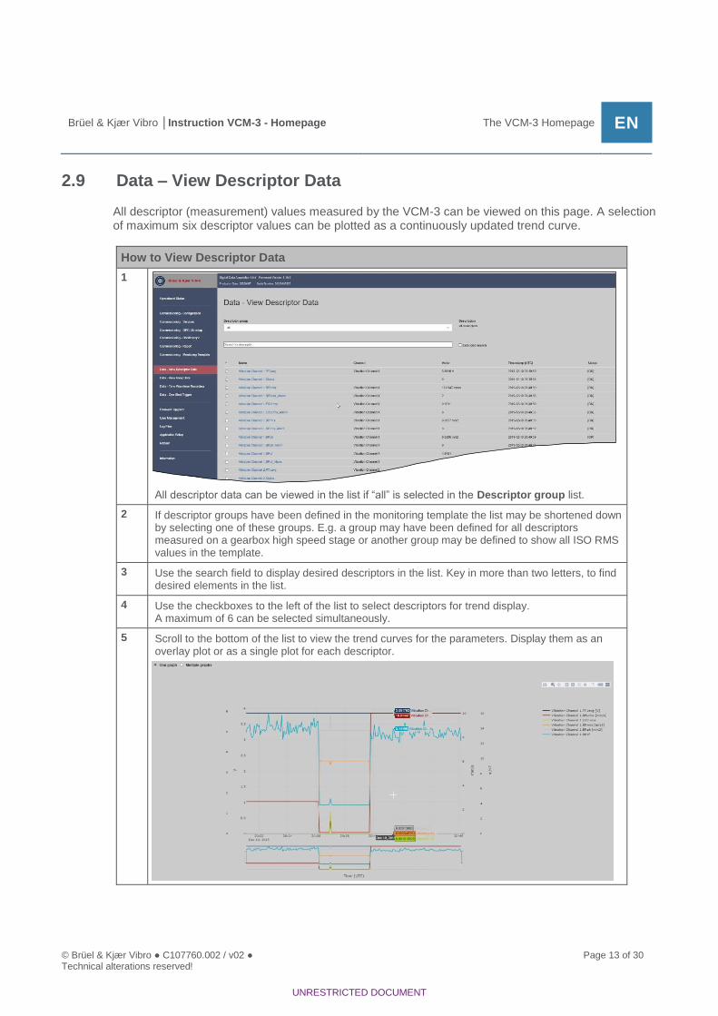
2.9 Data – View Descriptor Data
All descriptor (measurement) values measured by the VCM-3 can be viewed on this page. A selection of maximum six descriptor values can be plotted as a continuously updated trend curve.
How to View Descriptor Data
1
All descriptor data can be viewed in the list if “all” is selected in the Descriptor group list.
2 If descriptor groups have been defined in the monitoring template the list may be shortened down by selecting one of these groups. E.g. a group may have been defined for all descriptors measured on a gearbox high speed stage or another group may be defined to show all ISO RMS values in the template.
3 Use the search field to display desired descriptors in the list. Key in more than two letters, to find desired elements in the list.
4 Use the checkboxes to the left of the list to select descriptors for trend display. A maximum of 6 can be selected simultaneously.
5 Scroll to the bottom of the list to view the trend curves for the parameters. Display them as an overlay plot or as a single plot for each descriptor.

Page 14 of 30 © Brüel & Kjær Vibro ● C107760.002 / v02 Technical alterations reserved!
EN
UNRESTRICTED DOCUMENT
2.10 Data – View Array Data
The Array data which have been configured in the template can be displayed. That is, Auto-spectrum, Envelope spectrum, Cepstrum etc.
How to View Array Data
1 Click the desired array measurement from the list
2
After a little while – please be patient - the array measurement is displayed. The update rate is defined in the template, it will normally be around 15-20 seconds.
3 Select Automatic update to get the spectra updated automatically
4 Click Refresh to update the plot manually.

© Brüel & Kjær Vibro ● C107760.002 / v02 ● Page 15 of 30 Technical alterations reserved!
Brüel & Kjær Vibro │Instruction VCM-3 - Homepage The VCM-3 Homepage EN
UNRESTRICTED DOCUMENT
2.11 Data – Time Waveform Recording
NOTE!
Usage of this function requires that a minimum of one-time waveform trigger and one ring buffer have been defined in the monitoring template. You must have a description of the configured triggers and ring buffers in the actual template as a help to configure time waveform recording.
This function can be used to initiate an immediate download of time waveform files to a remote server or the PC running the browser with the homepage. The download format is a .json file. This can be applied by a diagnostic engineer when a machine fault is suspected. If the time waveform is downloaded to a server or directly to the PC, a conversion program is required which can convert the .json file to a format which is compatible with the tools for further analysis.
How to initiate a Time Waveform Recording with download to a remote server
1
Select Trigger remote download
2 Select the Trigger group. The trigger group is defined in the monitoring template and defines which ringbuffers shall be downloaded when the trigger is activated.
3 Specify the IP address of the Remote Server. A web service on the remote server must be available to receive the download request from the VCM-3.
4 Enter a Reference ID. This is a free text string used to identify the particular download
5 Specify Timeout (s). The remote server must have responded within the time specfied.
6 Specify number of Retries in case of timeout
7 Specify Delay (s). This is the period of time between retries
8 Click the Trigger button to activate the download

Page 16 of 30 © Brüel & Kjær Vibro ● C107760.002 / v02 Technical alterations reserved!
EN
UNRESTRICTED DOCUMENT
How to initiate a Time Waveform Recording with download to a local PC
1
Select Download locally.
2 Select the Trigger group. The trigger group is defined in the monitoring template and defined which ringbuffers shall be downloaded when the trigger is activated.
3 Specify if RPC header shall be included in the downloaded .json file. This is used if the files shall be sent to a remote WEB service
4 Enter a Reference ID. This is a free text string used to identify the particular download
5 Click the Trigger button to activate the download
2.12 Data – One Shot Trigger
NOTE!
Usage of this function requires that a minimum of one time waveform trigger, one ring buffer and one push job have been defined in the monitoring template. You must have a description of the available triggers, ring buffers and jobs in the actual template as a help to configure the one shot triggers.
The One Shot Trigger is activated once, and then forgotten by the VCM-3. Cyclic triggers can be defined via the monitoring template. A manual arming of a One Shot Trigger can be configured via this function. Once the defined trigger condition is fulfilled the raw data in the ring buffers linked to the trigger setup is downloaded to the remote server. The One Shot Trigger is a tool which can help the diagnostic engineer to get data in addition to the more regular data specified in the monitoring template and to get data under a certain machine condition. The data which is recorded as result of the defined trigger is downloaded to the server(s) specified in the selected Job. This is a so-called push job and must be part of the current monitoring template. The push job contains the IP address(es) of the server(s) which shall receive the data. If data are pushed to a server a web service on the remote server must be available to receive the download request from the VCM-3.

© Brüel & Kjær Vibro ● C107760.002 / v02 ● Page 17 of 30 Technical alterations reserved!
Brüel & Kjær Vibro │Instruction VCM-3 - Homepage The VCM-3 Homepage EN
UNRESTRICTED DOCUMENT
How to initiate a time waveform using One Shot Trigger
1
Select the descriptor to be used for defining the trigger condition.
2 Define the activation range for the trigger by defining the Lower limits and Upper limits of the selected descriptor.
3 Define the Margin and Time until trigger. This is a stability criteria where the margin defines the allowed variation of the descriptor in the defined time window when the descriptor value is in the activation range.
4 Select the Trigger ID. This ID defines which group of ring buffers shall be downloaded when the trigger is activated.
5 Select the Job. This defines the server destination(s) of the recorded ring buffer data.
6 Select which Buffers belonging to the trigger request shall be downloaded.
7 Click Send to activate the one shot trigger.

Page 18 of 30 © Brüel & Kjær Vibro ● C107760.002 / v02 Technical alterations reserved!
EN
UNRESTRICTED DOCUMENT
2.13 VCM-3 – Firmware Update
Contact Brüel & Kjær Vibro Technical support [email protected] to get information how to update your device.
Check firmware version
1
The Firmware Version number is located in the page header.
2.14 VCM-3 – User Management
You can define three user levels for the VCM-3 Homepage. You can add/update/delete a user if you have Administrator rights.
• Administrator has access to all functionality on the VCM-3 homepage
• Service user has access to all functionality except user management
• Ordinary user (a guest user) can only read the content of the WEB pages including making
the tap test.
You can add new users, update credentials for an existing user, and delete a user
How to add a user
1
Click Add User to add a new user
2 Specify username and password. The password must fulfill the rules specified in the Password rules section of the page.
3 Select user level for the user
4 Click Add when all fields have been specified

© Brüel & Kjær Vibro ● C107760.002 / v02 ● Page 19 of 30 Technical alterations reserved!
Brüel & Kjær Vibro │Instruction VCM-3 - Homepage The VCM-3 Homepage EN
UNRESTRICTED DOCUMENT
How to update a user
1
Click the line with the user to be edited.
2 Change Name and/or Password for the user. You cannot change user level. Observe the Password rules when defining the new password.
3 Click Update
How to delete a user
1
Click the wastebasket sign in the line with the user to be deleted.
NOTE!
You cannot delete the predefined users admin, service, vcm_admin, vcm_service
and user. You can only update their password. The active user is highlighted red.
2 Confirm the action when you are prompted.

Page 20 of 30 © Brüel & Kjær Vibro ● C107760.002 / v02 Technical alterations reserved!
EN
UNRESTRICTED DOCUMENT
2.15 VCM-3 – Log Files
Upon functional problems with the VCM-3 the log file system can be consulted. VCM-3 has several log files each related to a particular subject. Check the log files which you suspect may relate to the problem. E.g. if you have problems with the Modbus communication then consult the Modbus controller log. Often the information in the log indicates a problem which shall be reported to Brüel & Kjær Vibro. You can download the log file to your PC and send it by mail to Brüel & Kjær Vibro technical support: [email protected]
How to view and download Log Files
1
Select a log file, the log file will be displayed in the Log output window.
2 Click Download to download the selected log file to the PC running the browser. Attach the log file to an E-Mail and send it to Brüel & Kjær Vibro technical support ([email protected]) with a description of the problem you have encountered.

© Brüel & Kjær Vibro ● C107760.002 / v02 ● Page 21 of 30 Technical alterations reserved!
Brüel & Kjær Vibro │Instruction VCM-3 - Homepage The VCM-3 Homepage EN
UNRESTRICTED DOCUMENT
2.16 VCM-3 – Application Setup
This page allows the user to configure various settings for the VCM-3.
• Log level: This setting specifies the amount of information in the log files. In case of functional
problems select a log level with more information. This may provide valuable debug
information for the Brüel & Kjær Vibro technical support.
• Storage location: This setting allows the user to specify whether the VCM-3 internal memory
(4GB) or external memory – SD Card or USB memory shall be used. In this case the size of
the history buffer only depends upon the capacity of the external storage media.
Refer to Appendix 3 for more detailed information about external storage media.
Select the information (Log) level for the log files within the Application Setup.
1
Select the logging level for VCM-3. Select between various log levels, such as: Information, Warning, Error, Critical, Fatal
2 Save the new setting by clicking Save Changes.

Page 22 of 30 © Brüel & Kjær Vibro ● C107760.002 / v02 Technical alterations reserved!
EN
UNRESTRICTED DOCUMENT
Select storage location for the history buffer within the Application Setup
1
Select storage location: Internal: 4GB of internal Flash memory External: SD Card or USB memory stick. Refer to Appendix 3 for more detailed information about external storage media.
2 Save the new setting by clicking Save Changes.
2.17 VCM-3 – Reboot
How to Reboot a VCM-3 device
1
Click Reboot now to reboot. This process will take approximately 30 seconds. Login again after the reboot.

© Brüel & Kjær Vibro ● C107760.002 / v02 ● Page 23 of 30 Technical alterations reserved!
Brüel & Kjær Vibro │Instruction VCM-3 - Homepage The VCM-3 Homepage EN
UNRESTRICTED DOCUMENT
2.18 Information
In this section you can find a quick overview of the VCM-3 Homepage functionality. You may also upload your own information to service technicians.
View information
1
Click the link representing the information you want to view in the information field.
Download additional information
1
Fill in Download URL and Filename. If you want to view the file it must be on .PDF format
2 Click Download.

Page 24 of 30 © Brüel & Kjær Vibro ● C107760.002 / v02 Technical alterations reserved!
EN
UNRESTRICTED DOCUMENT
Remove information
1
Click waste bin basket in the line where you want the information to be removed.

© Brüel & Kjær Vibro ● C107760.002 / v02 ● Page 25 of 30 Technical alterations reserved!
Brüel & Kjær Vibro │Instruction VCM-3 - Homepage Appendix 1: Changing laptop network
connection EN
UNRESTRICTED DOCUMENT
3 Appendix 1: Changing laptop network connection
Below instruction tells how to change laptop network settings to be able to connect to the VCM-3.
NOTE!
IP address of the laptop and VCM-3 device must be different.
How to change network connection
1 Open Control Panel and navigate to the Network and Sharing Center.
2 Double click Network and Sharing Center and click Change adapter settings.
3 Click Change adapter settings, double click Local Area Connection on the list of networks

Page 26 of 30 © Brüel & Kjær Vibro ● C107760.002 / v02 Technical alterations reserved!
EN
UNRESTRICTED DOCUMENT
4 Select Internet Protocol… (1), then click Properties (2), on the Local Area Connection Properties window.
5 Click Use the following IP address on the Internet Protocol Version 4 (TCP/Ipv4) Properties window and fill in the address in the format as shown below. Note that the numbers in the red square (1) must not be the same as the used for the VCM-3. The empty fields should remain empty.

© Brüel & Kjær Vibro ● C107760.002 / v02 ● Page 27 of 30 Technical alterations reserved!
Brüel & Kjær Vibro │Instruction VCM-3 - Homepage Appendix 2: Notation for IP address ranges EN
UNRESTRICTED DOCUMENT
4 Appendix 2: Notation for IP address ranges
The VCM-3 uses the so-called CIDR notation to specify IP address ranges (CIDR - Classless Inter-Domain Routing). Example: 192.168.100.14/24 represents the IPv4 address 192.168.100.14 and its associated routing prefix 192.168.100.0, or equivalently, its subnet mask 255.255.255.0, which has 24 leading 1-bits. That is, an IP address is represented as 32-bit number. The number following the slash is the prefix length, that is the number of shared initial bits, counting from the most significant bit of the address. /24 indicates that the first 24 bits are shared leaving 8 bits to the subnet. This corresponds to the netmask 255.255.255.000. The table below shows examples of IP address ranges:
Address format
Difference to last address
Mask
Addresses
Decimal 2n
a.b.c.d/32 +0.0.0.0 255.255.255.255 1 20
a.b.c.d/31 +0.0.0.1 255.255.255.254 2 21
a.b.c.d/30 +0.0.0.3 255.255.255.252 4 22
a.b.c.d/29 +0.0.0.7 255.255.255.248 8 23
a.b.c.d/28 +0.0.0.15 255.255.255.240 16 24
a.b.c.d/27 +0.0.0.31 255.255.255.224 32 25
a.b.c.d/26 +0.0.0.63 255.255.255.192 64 26
a.b.c.d/25 +0.0.0.127 255.255.255.128 128 27
a.b.c.0/24 +0.0.0.255 255.255.255.0 256 28
a.b.c.0/23 +0.0.1.255 255.255.254.0 512 29
Reference: https://en.wikipedia.org/wiki/Classless_Inter-Domain_Routing

Page 28 of 30 © Brüel & Kjær Vibro ● C107760.002 / v02 Technical alterations reserved!
EN
UNRESTRICTED DOCUMENT
5 Appendix 3: External storage media for VCM-3
If history data should be stored on external media, under “Storage Location” the option “External” has to be selected.
NOTE!
To save history data internal or external, this has to be implemented in the Machine Monitoring Template.
5.1 Formatting
The SD card as well as the USB stick must be formatted by the user. The volume label must be ’HISTORY’.
5.2 Type of SD-card
Physical form factor The slot accepts the original size form factor card. Using an adaptor, the micro size format card can be used as well.
Bus format: The VCM-3 bus interface supports SD, SDHC and SDXC default bus speed 12.5 MB/s.
Speed class rating To get maximum writing speed (12MB/s), Class 10 (C10) or faster cards should be used
File system format FAT32 is supported presently by the VCM-3. SDXC cards are normally preformatted to utilize the exFAT filesystem, but can be reformatted to use any file system
Data size The VCM-3 has no limit as such on the maximum data size on the SD-card. The card technology and what you want to spend on the price is the limit.
5.3 Type of USB Storage
Any size storage device utilizing the USB interface should connect to the VCM-3. FAT32 and ext4 are supported presently by the VCM-3 configuration.

© Brüel & Kjær Vibro ● C107760.002 / v02 ● Page 29 of 30 Technical alterations reserved!
Brüel & Kjær Vibro │Instruction VCM-3 - Homepage Appendix 3: External storage media for VCM-3 EN
UNRESTRICTED DOCUMENT

Contact Brüel und Kjær Vibro GmbH
Leydheckerstrasse 10
64293 Darmstadt
Germany
Phone: +49 6151 428 0
Fax: +49 6151 428 1000
Brüel & Kjær Vibro A/S
Skodsborgvej 307 B
2850 Nærum
Denmark
Phone: +45 77 41 25 00
Fax: +45 45 80 29 37
BK Vibro America Inc
1100 Mark Circle
Gardnerville NV 89410
USA
Phone: +1 (775) 552 3110
Corporate E-Mail: [email protected] Homepage: www.bkvibro.com
VCM-3 - Homepage ● © Brüel & Kjær Vibro ● 06/2021 ● C107760.002 / v02 ●
Technical alterations reserved!