vibration based condition monitoring under · pdf filevibration based condition monitoring...
TRANSCRIPT

VIBRATION BASED CONDITION MONITORING UNDER NON-STATIONARY CONDITIONS
• Stephan Heyns
• Professor and Director: C-AIM
• C-AIM University of Pretoria
• South Africa

Introduction
• Existing physical assets aging - operational life
pushed to new limits - financial & environmental.
• Increasingly complex new assets commissioned.
• Reliability Availability Maintenance Safety (RAMS)
requirement increasing.
• Need cost-effective, robust condition based
maintenance (CBM) strategies.

Wind turbine gearboxes
In recent years
wind turbines
have sparked
great interest
in monitoring
of complex
machinery
during non-
stationary
operations

Mining gearboxes
A B
E F G
C
H
D
Tooth damage
Dragline Bucket
Drag Cables
Hoist Cables

Mining gearboxes
• Expensive gearboxes
• Highly fluctuating load and
speed conditions
• Reversals in direction of
rotation
• Load variations tend to
cause amplitude modulation,
rotational speed frequency
modulation

Why CM under fluctuating conditions?
• Difficult to create comparable operational
conditions unless equipment is unloaded.
• Monitoring under actual loaded conditions more
likely to show defects.
• Conventional CM methodologies often violate
underlying mathematical assumptions and new
approaches are necessary.

Agenda
1. Fundamental concepts in non-stationary
vibration based condition monitoring.
2. Applications.
3. New developments in the Centre for Asset
Integrity Management.
4. Conclusions.

1. Fundamental concepts
Fundamental concepts in non-stationary vibration
based condition monitoring:
• Synchronous averaging
• Order tracking
• Load demodulation normalization
• Instantaneous angular speed
• Phase domain averaging
• Discrepancy signals
• Sensorless signal resampling

Synchronous averaging
• Extracting periodic signals from a composite signal is based on averaging signal sections of the period sought.
• This does require a priori knowledge of the frequency sought.
Encyclopedia of Vibration p 102

Order tracking
Sampling at constant sampling
frequency (normal frequency analysis)
8 samples per rev
Sampling at fixed number of
times per shaft revolution
Shock and Vibration Handbook by C.M. Harris
Spectral peak
smeared over
various lines
Spectrum one line
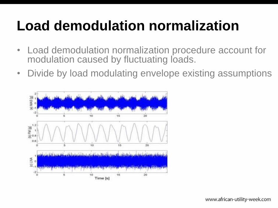
Load demodulation normalization
• Load demodulation normalization procedure account for modulation caused by fluctuating loads.
• Divide by load modulating envelope existing assumptions

Load demodulation normalization
• Envelope estimated as low pass filtered signal
maxima.
• Filter frequency optimized to ensure best
conformance between statistical properties of
signals measured under different load
conditions.
• Rotation domain averaging technique combines
ability of COT and time domain averaging to
suppress spectral smearing caused by speed
fluctuations and suppress amplitude of non-
synchronous vibrations.

Instantaneous angular speed
• IAS sensitive indicator of gear
condition
• IAS less susceptible to phase
distortions introduced by
transmission path compared to
gearbox casing vibration
measurements.

Phase domain averaging
• Reduce transmission path phase
distortion effects. Employ phase
domain averaging.
• Synchronous averaging with
regard to phase of reference
frequency.

Discrepancy analysis
Recently focus on low-cost condition monitoring
using empirical models such as:
• probability density functions and regression
functions
• to model complex machine response signals.
Special attention was given to discrepancy analysis

Discrepancy analysis
• Slide Models not data samples
Autoregressive filters
(linear steady state)
• Parallel adaptive AR filters
• SANC technique based on
LMS adaptive filter
• Schur filter
• Non-linear principal
components
• Likelihood measures based
on Gaussian mixture models
Neural network residual
envelopeTheo Heyns

Discrepancy transform
• Compare novel signal to reference signal(s) in piecewise manner
• Generate discrepancy transform which indicates where novel signal deviates from reference signal(s)
• Reference signal(s) representative of vibration response from healthy machine as subjected to different/fluctuating operating conditions
• Discrepancy signal expected to be smoother and simpler and subsequently less sensitive to frequency, amplitude and phase modulation.

Sensorless signal resampling
• Order tracking popular method to account for frequency modulation
• Due to physical and financial constraints not always possible to install an angular position reference sensor (e.g. tachometer)
• Different methodologies have been investigated where shaft speed/ angular position is directly estimated from signal itself
• Due to signal noise/ stochastic behaviour and cross frequency interference the angular position/speed estimates offer limited accuracy

2. Applications
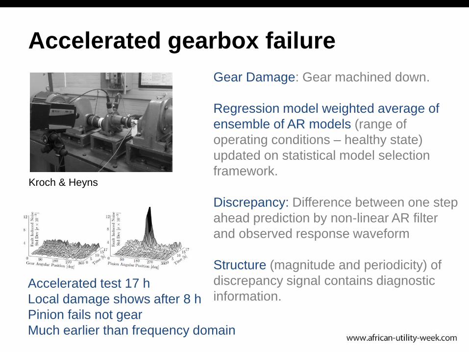
Accelerated gearbox failure
ACC Fan gearbox
Accelerated gearbox failure
Accelerated test 17 h
Local damage shows after 8 h
Pinion fails not gear
Much earlier than frequency domain
Gear Damage: Gear machined down.
Regression model weighted average of
ensemble of AR models (range of
operating conditions – healthy state)
updated on statistical model selection
framework.
Discrepancy: Difference between one step
ahead prediction by non-linear AR filter
and observed response waveform
Structure (magnitude and periodicity) of
discrepancy signal contains diagnostic
information.
Kroch & Heyns

Methodology
• Transform complex (containing lost of information) vibration signal into smoothed discrepancy signal
• Estimate approximate shaft speed based on analysis of original vibration signal
• Resample discrepancy signal to account for most significant frequency modulation
• Analyse resampled discrepancy signal by means of synchronous averaging or spectrum.

Application: ACC fan gearbox
• ACC fans widely used to
facilitate indirect dry cooling
– 48 fans required per unit
– 288 fans for 6 unit power station
• Recurrent failures of multi-
stage gearboxes at specific
power station
– Same gearboxes intended for
use in 2 new power stations
– 2-year vibration monitoring
programme

Methodology
• Current power station– 9m diameter fan – Hot air recirculation– Gearbox with helical gears– Pinion gear failures– Gear pump failures
• Vibration monitoring of gearbox over lifespan– Started a couple of months
after installation– November 2011 – November
2013
24t68t
18t
Dri
ve
moto
r
Brg 5/6
79tBrg 5/6
Gear pump
Brg 3/4
Brg 3/4
Brg 1
Brg 2
To fan
Shaft 1
Shaft 2
Shaft 3
1500 RPM
120.6 RPM

Methodology
• Three adjacent gearboxes instrumented– Single axis accelerometer (radial)– Tachometer– Thermocouple
• Data acquisition with eDAQ lite data logger– 2500 Hz sample frequency
• Recurrent pinion gear failures
• Initially bearing diagnostics were ignored
Boil
er s
ide
HV
yar
d s
ide
Gea
rbox
#1
Gea
rbox
#2
Gea
rbox
#3
Accelerometer position &
orientation
Tachometer
Thermocouple

Inner shaft lower taper roller bearing
• Two defects on outer race
• Locations correspond to NLL peak positions
• Movement of bearing outer ring in gearbox

3. New developments in C-AIM
Fundamental concepts in non-stationary vibration
based condition monitoring:
• Synchronous averaging
• Order tracking
• Load demodulation normalization
• Instantaneous angular speed
• Phase domain averaging
• Discrepancy signals
• Sensorless signal resampling

Optical flow measurement
Localised phase information of the
image convolved with a complex filter.
Very small vibrations.
450 x smaller than single pixel from
video sequence.
20 Hz
225 FPS
450 mm standoff distance
167 micron/pixel image
resolution

Optical flow measurement
• Up to a resolution/amplitude ratio of 50, the optical flow method is better than 1% accurate
• Optical flow worst performance of 5% error
• Much more accurate than conventional DIC
• Viable for cost-effective structural vibration measurement with the advantage of full field vision!

Incremental shaft encoders
• Measure shaft angular velocity.
• Normally has several pulses per revolution, as
opposed to one pulse.
• Has potential to measure torsional vibration
(e.g. gearboxes) for diagnostics etc.
• Instantaneous Angular Speed can potentially
be more sensitive to gear faults than
acceleration measurements.
• But IAS usually difficult to measure. Good
quality encoders difficult to install and
expensive.

Low cost zebra tape encoder
Stationary Piezoelectric
probe
Shaft
Zebra tape

Geometric effect illustration
Stationary probe
Butt joint

Method assumptions
• For a shaft encoder with N encoder increments and M recorded revolutions.
• Assume that the angular velocity is linearly varying throughout each increment.
• Assume that the shaft velocity is continuous throughout all shaft increments.
• There are 2MN unknowns and MN equations in system. System is underdetermined and has infinitelymany solutions.
• Bayesian linear regression can be used to addprior information about the system parameters.
• Very promising results for varying speed conditions.

Blade tip timing for detecting
turbomachine blade problems
Bayesian statistics
Pressure measurementssensitive microphone

Blade tip timing for detecting
turbomachine blade problems

Blade tip timing
• The mill is the
Strain gauge – TelemetryBlade Tip TimingScanning LaserHigh Speed photography
Gwashavanhu & Diamond

Mill monitoring
Poorly performing milling can cause a range of secondary issues:
• Unburnt carbon in ash
• High NOx emissions
• Uneven steam temperatures
• High exit gas temperatures
Salzwedel

Fault detection and diagnosis
• Use machine learning to extract features from
data to predict and diagnose coal mill failures.
• Three main sources of data:
• Analogue process signals
• Binary event signals
• Mill notifications

Mill notifications
• Natural language descriptions of faults, events
logged by operators, maintenance personnel
and engineers.
• Dirty, but informative. There are many different
ways to describe the same fault.
• Often include spelling errors, abbreviations:

Semantic labelling of operator logs
• Refine mill
notification clustering
• Correlate notification
clusters to process
data
• Train a deep neural
network to classify
failures based on
process signals.

4. Conclusions
• Explained need for CM under non-stationary
conditions
• Introduced a number of very important concepts
in condition monitoring under non-stationary
conditions
• Shown a number of applications
• Introduced proposing new developments in the
C-AIM

Acknowledgements
I am pleased to acknowledge the critical research
contributions of the following C-AIM post-graduate students
and researchers:
• Dr Corné Stander
• Berndt Eggers
• Dr Abrie Oberholster
• Dawie Diamond
• Benji Gwashavanhu
• Robert Salzwedel
and the Eskom Power Plant Industry Programme (EPPEI)