viability of applying curie point pyrolysis/gas...
TRANSCRIPT

SANDIA REPORTSAND2002-1922Unlimited ReleasePrinted July 2002
Viability of Applying Curie PointPyrolysis/Gas ChromatographyTechniques for Characterization ofAmmonium Perchlorate BasedPropellentsJames Barnett and Bertha M. Montoya
Prepared bySandia National LaboratoriesAlbuquerque, New Mexico 87185 and Livermore, California 94550
Sandia is a multiprogram laboratory operated by Sandia Corporation,a Lockheed Martin Company, for the United States Department ofEnergy under Contract DE-AC04-94AL85000.
Approved for public release; further dissemination unlimited.

Issued by Sandia National Laboratories, operated for the United States Departmentof Energy by Sandia Corporation.
NOTICE: This report was prepared as an account of work sponsored by an agencyof the United States Government. Neither the United States Government, nor anyagency thereof, nor any of their employees, nor any of their contractors,subcontractors, or their employees, make any warranty, express or implied, orassume any legal liability or responsibility for the accuracy, completeness, orusefulness of any information, apparatus, product, or process disclosed, or representthat its use would not infringe privately owned rights. Reference herein to anyspecific commercial product, process, or service by trade name, trademark,manufacturer, or otherwise, does not necessarily constitute or imply its endorsement,recommendation, or favoring by the United States Government, any agency thereof,or any of their contractors or subcontractors. The views and opinions expressedherein do not necessarily state or reflect those of the United States Government, anyagency thereof, or any of their contractors.
Printed in the United States of America. This report has been reproduced directlyfrom the best available copy.
Available to DOE and DOE contractors fromU.S. Department of EnergyOffice of Scientific and Technical InformationP.O. Box 62Oak Ridge, TN 37831
Telephone: (865)576-8401Facsimile: (865)576-5728E-Mail: [email protected] ordering: http://www.doe.gov/bridge
Available to the public fromU.S. Department of CommerceNational Technical Information Service5285 Port Royal RdSpringfield, VA 22161
Telephone: (800)553-6847Facsimile: (703)605-6900E-Mail: [email protected] order: http://www.ntis.gov/ordering.htm

3
SAND2002-1922Unlimited ReleasePrinted July 2002
Viability of Applying Curie Point Pyrolysis/GasChromatography Techniques for Characterization of
Ammonium Perchlorate Based Propellants
James Barnett and Bertha M. MontoyaExplosive Materials and Subsystems Department
Sandia National LaboratoriesP.O. Box 5800
Albuquerque, NM 87185-1452
Abstract
Curie Point pyrolysis-gas chromatography was investigated for use as a tool forcharacterization of aged ammonium perchlorate based composite propellants (1).Successful application of the technique will support the surveillance program for theExplosives Materials and Subsystems Department (1). Propellant samples were preparedby separating the propellant into reacted (oxidated) and unreacted zones. Theexperimental design included the determination of system reliability followed by,reproducibility, sample preparation and analysis of pyrolysis products. Polystyrene wasused to verify the reliability of the system and showed good reproducibility. Applicationof the technique showed high variation in the data. Modifications to sample preparationdid not enhance the reproducibility. It was determined that the high concentration ofammonium perchlorate in the propellant matrix was compromising the repeatability ofthe analysis.

4
Table of Contents
Abstract ..............................................................................................................................................................................3Table of Contents .............................................................................................................................................................4Table of Figures ................................................................................................................................................................5Table of Tables .................................................................................................................................................................6Introduction.......................................................................................................................................................................7Experimental Design........................................................................................................................................................7
Curie Point Pyrolyzer .................................................................................................................................................7Gas Chromatograph..................................................................................................................................................10Sample Preparation...................................................................................................................................................11System Reproducibilty...............................................................................................................................................13Sample preparation and pyrolysis of Ammonium Perchlorate based propellants .........................................14Sample preparation of AP-based propellants .......................................................................................................17Open foil pyrolysis of AP-based propellants.........................................................................................................23Sample preparation isolating solid organics from inorganics in AP-based propellants ..............................27
Conclusions.....................................................................................................................................................................28References .......................................................................................................................................................................31

5
Table of Figures
Figure 1: JHP-3 Curie Point Pyrolyzer........................................................................................................................9Figure 2: Assembled pyrolyzer, GC and data acquisition system.........................................................................11Figure 3: Crimper and crimped pyrofoil boat............................................................................................................12Figure 4: Pyrofoil boat with sample and flattened pyrofoil.....................................................................................12Figure 5: Overlaid pyrograms of polystyrene Mw 2600. The monomer, dimer and trimer peaks are
staggered with respect to the retention time axis due to staggering of the overlays..................................13Figure 6: Peak number vs area percent mean +/- 99% confidence interval polystyrene Mw 2600 showing
reproducibility of polystyrene. ............................................................................................................................14Figure 7: Peak number vs. area percent mean +/- 99% confidence interval unreacted zone 34 year old
propellant. ...............................................................................................................................................................15Figure 8: Peak number vs average area percent +/-99% confidence interval unreacted zone vs reacted zone.
..................................................................................................................................................................................16Figure 9: Sample holder, end cap and SS ball bearing . This assembly is liquid nitrogen chilled prior to
inserting in SS manifold for ball mill agitation................................................................................................17Figure 10: Pulverized condition of the propellant shavings after the ball-mill process....................................18Figure 11: Comparison of the pyrogram statistics of pulverized SN-1035-I6 to shavings of the same
material. No improvement is noted....................................................................................................................19Figure 12: Comparison of the unreacted zones of the two different ages of the AP-based propellant.
Tighter error bars for the younger propellant were not universally observed. ...........................................20Figure 13: The modified vise-grip technique did not improve the reproducibility of the technique as the
error bars indicate..................................................................................................................................................21Figure 14: Average area% and 99% confidence interval error bars for the pyrolysis of both the pulverized
and shavings of Hipel propellant. Both yield similar average area % distributions..................................22Figure 15: Open pyrofoil pyrolyses of THF extracts.............................................................................................24

6
Table of Tables
Table 1: Open foil pyrolysis of organic ingredients of AP-based propellant in THF extract. .........................26Table 2: Excellent precision was achieved with open foil pyrolysis of these soluble components in IPA....26Table 3: Weights of AP-based propellants before and after extraction with DI water. % lost does not
account for all the inorganic material including the ammonium perchlorate..............................................27Table 4: Weights of AP-based propellants before and after extraction with DI water......................................28
7
Introduction
Surface reactions due to aging of propellants can adversely affect the ignition andcombustion characteristics of these deflagrating materials. Ultimately, burn rate orexplosive sensitivity could yield out-of specification results rendering the propellantuseless. The surveillance program utilizes many bulk methods such as thermalgravimetric analysis (TGA) and differential scanning calorimetry (DSC) to evaluateand/or predict the performance of these propellants. However, these bulk techniques havedifficulty addressing the potential chemical difference between propellant surface reactedzones (thin veneers) and the internal bulk material. Pyrolysis is a technique that acceptsmicrogram sample sizes, and would complement existing bulk analysis. It would alsocomplement the microscopic visual imaging techniques that currently exist, as a smallsample from the visualized reacted zone would be enough for this pyrolysis technique.Together the data from these techniques could be used to predict propellant performance.
Pyrolysis is the characteristic breaking apart of large molecules into smaller onesusing only thermal energy. This technique has been successfully applied to the analysisof macromolecules such as polymers and is routinely used to analyze complex substancessuch as tire rubber, textiles, dried paint, glue, paper coatings, petrochemical sources, plantmaterials, coal and bacteria (2). Since most of these materials are primarily organic innature, pyrolysis applications specific to these compounds are organic matrix analyses (3).
The most critical elements of a pyrolysis unit are the uniformity andreproducibility of the temperature. These elements should yield the same thermal energyand therefore the same (reproducible) bond cleavage patterns for a given molecule or setof molecules. Reaching the pyrolysis temperature quickly is also important. This allowsthe thermally desorbed compounds and pyrolytically cleaved macromolecule fragmentsto be transferred to a gas chromatograph (GC) capillary column as a narrow band. Toachieve this performance a curie point pyrolyzer was chosen (4).
Experimental Design
Curie Point Pyrolyzer
The Curie Point pyrolyzer uses a radiofrequency (RF) generator and aferromagnetic foil. A ferromagnetic foil was inductively heated by a 225 watt 930 kHzRF coil to its curie point. The curie point is the point where the Pyrofoil loses itsmagnetic properties and energy is no longer absorbed so the temperature ceases to rise.The Temperature Raise Time (TRT) was only 0.2 sec and is reproducible. The resultingsystem reaches temperature quickly with reproducible analytical results. The system usedwas the Japan Analytical Instrumentation JHP-3 Curie Point Pyrolyzer.
The transfer tubing needle was installed into the GC column inlet with a heatersurrounding it to avoid cold spots and potential cold trapping of hot pyrolyzate gases. Theµgrams of sample were wrapped in a pyrofoil and inserted in a quartz sample tube. The

8
sample tube was installed through the airlock valve without interrupting the carrier gasflow. The pyrolyzer was subsequently purged of air via the purge gas inlet and leakvalve. This design allowed for rapid sample throughput without disruptingchromatographic conditions.
Pyrolysis temperature and initial sample size limits were established withrecommendations from several literature sources. A temperature of 590°C and a samplesize between 320 and 420 µg was chosen for this investigation.
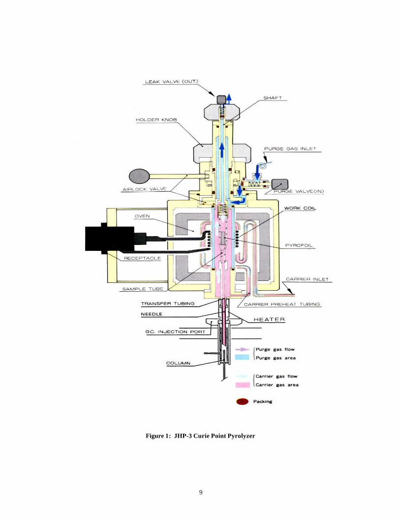
The pyrolysis unit oven and transfer tubing heater was set at a temperature of200°C to prevent cold trapping. A pyrolysis time of three seconds was considered to bethe optimum pyrolysis time for the relatively low molecular weight organic compoundsin the propellant. The organic content of the AP-based propellant was less than 0.25 %.The selected pyrolysis time ensured complete pyrolysis and thermal desorption. Thehelium flow through the pyrolyzer and into the GC inlet was set at 54 mL/min to affect arapid sweep of the pyrolyzate gases onto the GC columns. The JHP-3 was mounted onthe GC inlet. Figure 1 shows a diagram of the Curie Point pyrolyzer and gas flowthrough the system.
9
Figure 1: JHP-3 Curie Point Pyrolyzer

10
Gas Chromatograph
The gas chromatography (GC) system utilized a three-column orientation withdual detectors and computer software for acquiring and integrating the two signals. Thetriple column assembly allowed the use of a vent column and two columns of differentselectivity (polarity) providing the best separation for both polar and non-polarcompounds (4).
All analyses were performed using the following parameters:
• Analytical columns: consisted of two capillary columns in parallelboth 30 m long x 0.32 mm I.D. a 0.25µm film thickness stationaryphases. The stationary phases were DB-1 and DB-FFAP.
• The third column was the splitter or vent column and was 3 m long x.32 mm.
• Carrier gas flow was set at 2.0 mL/min/ analytical column and 50ml/min for the vent column.
• The injector temperature was set at 225°C.• Detectors were dual flame ionization detectors (FIDs).• Detector makeup gas flow was 30 mL/min/ detector.• Detector flame fuel gases were hydrogen flowing at
30mL/min/detector and air flowing at 300mL/min/detector;• Detector temperature at 300°C.• Detector sensitivity: 10-11 Amperes Full Scale/mV.• The column oven program: 50 ° C (2 minute hold) to 200 ° C at 10 °
C/min (10 min hold).• Total analysis time 27 minutes.
Data acquisition was accomplished using a Dell Optiplex XMT 5100 with VarianStar Chromatoghaphy Workstation version 4.51. The analytical assembly is pictured inFigure 2.

11
Figure 2: Assembled pyrolyzer, GC and data acquisition system.
Pyrolysis data utilized in this study had to be acquired from the DB-1 column.The DB-FFAP column did not perform satisfactorily upon multiple pyrolyses of actualAP-based propellants. The DB-FFAP as mentioned previously is a high polarity columnand will show high retention for polar compounds many of which are oxygenates. Thepyrolysis of an oxidant created an oxidizing environment. This environment createdmany oxygen-containing compounds. Retention of these compounds on the DB-FFAPcolumn ultimately led to active sites on this column and thus peak tailing. The DB-1showed no preferential retention for these oxygenates and did not retain thesecompounds. Comparison of the data showed that the DB-1 was robust in this applicationand the DB-FFAP was not. This is evidence of adverse oxidation reactions occurringduring pyrolysis of AP-based propellants.
Sample Preparation
A foil crimper was used to make a boat shape out of a 590°C Pyrofoil seen inFigure 3. Approximately 400µg of polystyrene molecular weight (MW) 2600 atomicmass units (amu) was weighed out and placed in the middle of the pyrofoil boat. Thepyrofoil was then folded around the sample and then placed in the pyrofoil tube as shownin Figure 4. The flattened foil was placed in the quartz sample tube and was screwed onto the holder assembly. This assembly was then attached to the top of the airlock with ano-ring seal. Once the assembly was sealed, the purge gas valve was opened and heliumwas purged through the leak valve three times on one-minute intervals. This step wasused to ensure that air and most importantly oxygen was purged from the system to avoidadverse oxidation reactions from taking place. With the sample holder purged, theairlock could then be opened and the quartz tube sample holder plunged into thepyrolyzer oven. The sample was given five minutes to come to temperature equilibriumwithin the oven. Then, pyrolysis was carried out for three seconds.

12
Figure 3: Crimper and crimped pyrofoil boat.
Figure 4: Pyrofoil boat with sample and flattened pyrofoil.
CRIMPER
Crimpedpyrofoil boat
Foil after flattening
Pyrofoil boat with 320to 420µg sample

13
System Reproducibilty
The sample preparation and analysis was repeated for several replicates on thesame polystyrene sample to investigate the reproducibility of the technique. Polystyreneis a commonly used calibration standard because of the reproducibility of threesignificant peaks per pyrogram consisting of the monomer, dimer and trimer ofpolystyrene (Figure 5). These three peaks plus several prominent peaks were chosen forarea integration for comparison between the pyrogram replicates. Small sample sizevariances are apparent in the visible peak height differences on the staggered polystyrenepyrograms. Subsequently, the integrated area for each peak inclusive of the monomer,dimer, trimer and the several prominent peaks for every pyrogram was divided by thesum total area of all these peaks in the pyrogram and multiplied by 100 to yield the areapercent of each peak. The average relative percent standard deviation was 3.747. Evenwith sample size differences on the order of two as reflected in the total areas the highest%RSD was approximately 16% with all others being less than 10%. The pyrolysismethod was highly reproducible for this polystyrene matrix.
Figure 5: Overlaid pyrograms of polystyrene Mw 2600. The monomer, dimer and trimer peaks arestaggered with respect to the retention time axis due to staggering of the overlays.
monomer
dimer trimer

An additional presentation of the pyrolysis data of polystyrene is shown in error bar form in Figure 6. This presentation was made to show the high degree of reproducibility the polystyrene Mw 2600 amu pyrolysis achieved. Again, the method appears to have great potential.
60 -n-
70 -
60 - - 50 - E 3 4 0 -
e: 30- l 2 0 -
X 10 - * x 0 - * * V V Y V V y
-10 J 2 4 6 a i o 12 14
peak number
Figure 6: Peak number vs area percent mean +/- 99% confidence interval polystyrene Mw 2600 showing reproducibility of polystyrene.
In Figure 6, peak numbers replaced retention times in ascending order, i.e. the earliest retention time was peak number 1 and the latest retention time was peak number 13. The variances were generally very small about the average area % showing good reproducibility between pyrolyses of the polystyrene Mw 2600 amu.
Sample preparation and pyrolysis of Ammonium Perchlorate basedpropelkants
Once system reliability and reproducibility were established, pyrolysis of A€- based ppellants was initiated. The 300-400 pgm shaving of propellant was then placed in a pyrofoil and folded using a needle nose plier crimping technique. The pyrolyzer was purged of air and the sample allowed to equilibrate at the pyrolyzer oven temperature as previously described. Pyrolysis was performed as per conditions expressed above.
The first A€-based propellant samples analyzed were the unreacted zone of SN1035-16, a 34 year old propellant. Again prominent and characteristic peaks for the six successive runs of this sample were chosen to evaluate the achievable reproducihilitv
14

15
from the DB-1 column signal. Ten such peaks were used for the statistical breakdown ofthe area% data into average area %, standard deviation, variance and %RSD shown inFigure 6. Examination of the statistics shows much poorer reproducibility for thesuccessive propellant analyses versus the polystyrene analyses. Only one %RSD wasbelow 10% and over half the %RSDs were over 20%.
Area percent with +/- 99% confidence interval (variance) error bar presentation ofAP-based propellant pyrolysis data was calculated. Peak numbers replace retention timesin ascending order, i.e. the earliest retention time was peak number 1 and the latestretention time was peak number 10. The variances are generally a large percentage of theaverage area % showing poor reproducibility between pyrolyses of the unreactedSN1035-I6, 34-year-old propellant.
-10
0
10
20
30
40
50
60
70
80
0 2 4 6 8 10 12
peak number
area
per
cent
Figure 7: Peak number vs. area percent mean +/- 99% confidence interval unreacted zone 34 yearold propellant.
The second AP-based propellant samples analyzed were both the reacted andunreacted zones of SN74C79, a 21 year old propellant. The reacted zone of thispropellant was more darkly colored and more brittle than the unreacted zone and it washoped that a marked difference in the pyrolysis signature of the two zones would beobserved. Five replicates each of both zones were run and characteristics peaks werechosen for data reduction that was performed as in Figure 7 for the SN1035-I6 propellant.It was immediately observed that the prominent characteristic peaks for both theunreacted and reacted zones were identical. No new peaks appeared or pre-existingpeaks disappeared between the two zones. The overlay of the two data sets with errorbars in Figure 8 further demonstrates that no real differences can be discerned betweenthe two zones by pyrolysis signature.

16
-10
0
10
20
30
40
50
60
70
80
0 2 4 6 8 10 12 14 16
peak number
aver
age
area
per
cent
.
Figure 8: Peak number vs average area percent +/-99% confidence interval unreacted zone vsreacted zone.
Unloaded 590°C pyrofoils were folded, crimped and pyrolyzed as system blanksto verify that these blank pyrofoils were not contributing background to the AP-basedpropellant characteristic peaks and thus perturbing the reproducibility. A standardpyrofoil blank run was performed after conditioning the column. The quartz tube waspropane cleaned. This process was initiated promoting a method change where the quartztube was propane flame cleaned daily before pyrolysis. The column was alwaysconditioned before pyrolysis with the exception of the worst-case blank pyrofoilexperiment. The blank pyrofoils were not found to significantly contribute to thepyrogram background in the area of interest and were dismissed as a factor causing theirreproducibility.
Since even the worst-case blank pyrofoil contribution was insignificant, this highdegree of irreproducibility was attributed to the complexity of the matrix, which waspredominately inorganic ammonium perchlorate. However, attempts were made atpyrolyzing the reacted zone of the same propellant in hopes that significant changeswould be observed. If only changes in peak area percents were observed, then thesewould have to exceed the error bar variances to be deemed “real” changes. Six replicatesof the reacted zone of SN-1035-I6 were then pyrolyzed. The data was then examined fornew or missing peaks or real changes in the area percentages of existing peaks.
The large error bars indicative of pyrolysis irreproducibilty were inhibiting theability to make distinctions between the zones of the two ages of propellants alreadyaddressed. Due to the sample matrix complexity perhaps the trivial sample preparation ofshaving off chunks of propellant was inadequate to achieve a homogenous sample.

17
Sample preparation of AP-based propellants
Due to the sample matrix complexity a cryogenic crushing preparation techniquewas adopted (3). The propellant is chilled in liquid nitrogen below its glass transitionpoint and ball-milled to a fine powder. The cryogenic crusher to perform this task wasunavailable at the time so a modified version was used.
A standard ball mill accepting stainless steel cylinders (sample holders) ofapproximate dimensions of 3cm long by 1cm in diameter enclosing a stainless steel (SS)ball and sealed with an end cap were utilized as seen in figure 8. The propellant shavingsin the hundreds of milligram mass range was transferred to one of these cylinders withthe SS ball inserted and the end cap attached. This whole assembly was lowered into adewar of liquid nitrogen for a period of 5 minutes to chill the contents below the glasstransition point of the propellant. The SS cylinder was inserted into the manifold andagitated for 5 minutes. This process was then repeated three more times to achieve thepulverized, finely divided condition of the propellant. The propellant before and afterpulverization is shown in Figure 9.
Figure 9: Sample holder, end cap and SS ball bearing . This assembly is liquid nitrogen chilled priorto inserting in SS manifold for ball mill agitation.

18
Figure 10: Pulverized condition of the propellant shavings after the ball-mill process
Five replicates of the pulverized version of SN-1035-I6 were performed and thedata was manipulated to generate the average area % and 99% confidence interval errorbars. Comparison of this data to the shavings data for the same propellant showed nosignificant improvement in reproducibility as seen in Figure 10. Since the same degreeof reproducibility was achieved with or without pulverizing the propellant, the chances ofachieving a homogenous sample with a high degree of reproducibility appeared moreremote.
Pulverizedpropellant
Propellantshavings

19
Figure 11: Comparison of the pyrogram statistics of pulverized SN-1035-I6 to shavings of the samematerial. No improvement is noted.
The older samples exhibited less homogeneity. The unreacted and reacted zonesof 21 year old propellant SN74C79 had previously demonstrated more overlap in theaverage area % than the same zones of the older SN-1035-I6 propellant. This had beenassumed to be due to less aging and, therefore, less chemical dissimilarity.Consequently, comparing the older SN-1035-I6 propellant reacted and unreacted zones tothe younger SN74C79 propellant reacted and unreacted zones respectively shoulddemonstrate less error for the younger (21 year old) SN74C79 propellant versus the older( 34 year old) SN-1035-I6 propellant (Figure 12). The data does not reinforce thisinterpretation as the error was not consistently less for the younger propellant versus theolder. In addition, the error was so significant as to prohibit distinguishing between thetwo ages of a given zone on the whole. Additionally, the appearance of peaks in thereacted or unreacted zone of a particular age, which may have been absent in the otherage, are either too diminutive or too irreproducible to rely on as characteristic peaks fordifferentiation. The method remains too variable to correlate younger age to betteroverlap and less error.
-10
0
10
20
30
40
50
60
70
80
0 2 4 6 8 10 12
peak number
aver
age
area
per
cent
pulverized average area % shaved average area %

20
Figure 12: Comparison of the unreacted zones of the two different ages of the AP-based propellant.Tighter error bars for the younger propellant were not universally observed.
In order for pyrolysis to succeed for this application a more reproduciblepyrogram from replicate to replicate had to be achieved. Since finely dividing the samplematrix had not helped and age and irreproducibility could not be directly correlated, otheraspects affecting the pyrolysis would need to be investigated.
For the above reason a different pyrofoil crimping technique was evaluated. Thisinvolved the use of a modified vise-grip that could have the closure pressure preset by anadjustable bolt on the handle (4). The vise-grip was used to eliminate the non-uniformneedle nose pliers crimping that had formerly been employed. The modified vise-gripalso left a cylindrical conduit along one edge of the flattened pyrofoil that was tofacilitate the movement of pyrolysate gases from the foil. This would minimizeadditional inter-reactions and would improve reproducibility. Five replicates ofpulverized SN-1035-I6 prepared with the new technique were compared to the 5 run byneedle nose plier crimping and no significant improvement was observed (Figure 13).Thus, the pyrofoil crimping technique was removed from consideration as a factor in thereproducibility problem.
-10
0
10
20
30
40
50
60
70 80
0 2 4 6 8 10 12 14 16 peak number
aver
age
area
per
cent
avg % unreacted zone sn74c79 avg % unreacted zone sn1035i6

21
Figure 13: The modified vise-grip technique did not improve the reproducibility of the technique asthe error bars indicate.
The hypothesis that the pyrolysis data was of a random nature because the sampleaging process had created a heterogeneous matrix was then investigated. None of thepropellants tested to this point were new unaged baseline materials.
A baseline factory fresh sample of AP based propellant was needed for pyrolysistesting. Hipel 430 TU47548 was used for this purpose. This material was immediatelysubjected to the more rigorous sample preparation of cooling and subsequent ball millingwith a notable difference between the Hipel and the aged propellants. The agedpropellants were initially harder materials, probably due to cross-linking associated withaging, and therefore, close enough to their glass transition point to crunch to a finepowder using this technique. The Hipel, on the other hand, was much more pliable andthis technique did little more than cause the material to extrude as a sheet. The smallestpieces of this material had sample weights between 30 to 60 µgms and these weresubjected to pyrolysis analysis. Since no difference in reproducibility was observedbetween the trivial needle-nosed pliers flattening of the foil and the vise-grip techniqueall these foils were flattened with the needle nosed pliers. Again, some of thecharacteristic pyrolysis peaks for this
-10
0
10
20
30
40
50
60
70
80
0 2 4 6 8 10 12
peak number
aver
age
area
per
cent
average percent reg crimp avg percent Vise-grip crimp

22
propellant exhibited %RSD’s for replicates of greater than 20% as shown in Figure 14.The freshest AP-based propellant sample available still demonstrated large statisticalvariation all but eliminating sample age as the primary source of the irreproducibility.
Figure 14: Average area% and 99% confidence interval error bars for the pyrolysis of both thepulverized and shavings of Hipel propellant. Both yield similar average area % distributions.
Even though the crushed versus shaved state of the older propellant material hadpresented no statistical advantage, a demonstrator model of a cryogenic crusher fromDychrome was applied to the Hipel propellant to finely divide this material and verifythat aging effects were not factors in the pyrolysis irreproducibility. The cryogeniccrusher utilized virtually the same stainless steel cylindrical sample holder, SS ball andendcap as previously described. The advantage presented by this device was the abilityto agitate the sample while it was being chilled in liquid nitrogen. After 15 minutes ofcryogenic crushing the resulting Hipel propellant was a finely divided material asthouroughly homogenized as possible.
However, as with the older propellant, the pulverized version of the Hipel stillpyrolyzed with marked variability in the first 3 replicates attempted. No differencebetween shavings or pulverized material could be determined and, in general, nodifferences in ages or zones of propellants of similar formulation could be discerned.
-5
0
5
10
15
20
25
30
35
40
45
50
0 2 4 6 8 10 12
peak number
aver
age
area
per
cent
pulverized material extruded shavingsl

23
Open foil pyrolysis of AP-based propellants
A relatively simple experiment was designed to verify the reproducibility of openfoil pyrolysis. Solvated compounds can be easily applied to a wire by dipping the wire inthe solvent. Once the pyrofoil is folded into the boat configuration a small depression inthe middle of the boat allows for the introduction of a liquid sample from a syringe. Onehundred mg of AP-based propellants underwent extraction in 10 mL of tetrahydrofuran(THF) and were subsequently filtered with a 0.45 µm Teflon filter to remove undissolvedmaterials or flocculants. Those THF soluble components of the AP-based propellantwere now evenly dispersed in the solvent and an aliquot of 10 uL was carefully added tothe pyrofoil boat drop by drop. Adding the sample drop by drop ensured quickerevaporation of the solvent to prevent wetting the entire foil and possibly losing somematerial. Again it must be reiterated that this test was designed to evaluate the efficacyof open foil pyrolysis and not to be considered method development for differentiation ofages of AP-based propellants. Basically, the solvation process would discriminate thesample on the basis of solubility and possibly disrupt existent cross-linking. Theseprocesses could easily mask the subtle changes being sought in the aging of AP-basedpropellants. However, if the pyrolysis of these solvent applied compounds in an open foilwas reproducible then further investigation into applying the solid phase to the wirewould be warranted.
The pyrolysis of THF solvent extractions of both unreacted and reacted zones ofAP-based propellant SN-1045-I6 (34 years old) was attempted with open foil technique.Prior to pyrolyzing the extracts, blank THF was pyrolyzed to determine if the solventresidue would contribute peaks to the pyrogram. Only diminutive peaks were observedand these were excluded from consideration in deriving the characteristic peaks in thepyrograms. The solvent extraction did, as was expected, alter the relative abundance ofsome characteristic peaks and “cleaned up” the pyrograms seen in Figure 14. The loss ofmuch of the peak definition and the change in relative abundance of characteristic peaksis primarily due to solubility limitations of these various components in THF. Althoughnot representative of the bulk material, this solution of the THF soluble componentsshould be a fairly homogenous sample resulting in reproducible pyrograms.

24
Figure 15: Open pyrofoil pyrolyses of THF extracts.
Unfortunately, pyrolysis of 5 replicates of the THF extracts of unreacted SN-1035-I6 still demonstrated high variation. For simplicity and due to the “clean”pyrogram, only 4 characteristic peaks were evaluated. Of these 4 peaks all of the %RSDswere over 15% and two were over 20%. The open foil pyrolysis technique had notimproved the repeatability of the pyrolyses.
The irreproducibility could be either attributed to the matrix or the open foilpyrolysis technique. The matrix, even though solubilized in THF would retain someequilibrium amounts of inorganics, primarily ammonium perchlorate, a strong oxidizer,that could adversely affect the pyrolysis. The open foil pyrolysis technique could haveinherent reproducibility problems. Unlike the crimped foil which guarantees intimatecontact of sample surfaces to the ferromagnetic foil and, therefore, better heat transfer,
Solid shavingpyrogram
Extractpyrogram
25
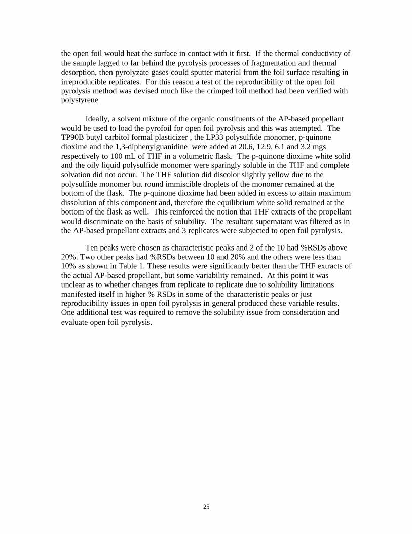
the open foil would heat the surface in contact with it first. If the thermal conductivity ofthe sample lagged to far behind the pyrolysis processes of fragmentation and thermaldesorption, then pyrolyzate gases could sputter material from the foil surface resulting inirreproducible replicates. For this reason a test of the reproducibility of the open foilpyrolysis method was devised much like the crimped foil method had been verified withpolystyrene
Ideally, a solvent mixture of the organic constituents of the AP-based propellantwould be used to load the pyrofoil for open foil pyrolysis and this was attempted. TheTP90B butyl carbitol formal plasticizer , the LP33 polysulfide monomer, p-quinonedioxime and the 1,3-diphenylguanidine were added at 20.6, 12.9, 6.1 and 3.2 mgsrespectively to 100 mL of THF in a volumetric flask. The p-quinone dioxime white solidand the oily liquid polysulfide monomer were sparingly soluble in the THF and completesolvation did not occur. The THF solution did discolor slightly yellow due to thepolysulfide monomer but round immiscible droplets of the monomer remained at thebottom of the flask. The p-quinone dioxime had been added in excess to attain maximumdissolution of this component and, therefore the equilibrium white solid remained at thebottom of the flask as well. This reinforced the notion that THF extracts of the propellantwould discriminate on the basis of solubility. The resultant supernatant was filtered as inthe AP-based propellant extracts and 3 replicates were subjected to open foil pyrolysis.
Ten peaks were chosen as characteristic peaks and 2 of the 10 had %RSDs above20%. Two other peaks had %RSDs between 10 and 20% and the others were less than10% as shown in Table 1. These results were significantly better than the THF extracts ofthe actual AP-based propellant, but some variability remained. At this point it wasunclear as to whether changes from replicate to replicate due to solubility limitationsmanifested itself in higher % RSDs in some of the characteristic peaks or justreproducibility issues in open foil pyrolysis in general produced these variable results.One additional test was required to remove the solubility issue from consideration andevaluate open foil pyrolysis.

26
Table 1: Open foil pyrolysis of organic ingredients of AP-based propellant in THF extract.
Propellant ingredients in THF 3/20/2000#1 #2 #3
Retention TimeArea % Area % Area % Avg. Area % Std. Dev. variance % RSD1.735 17.00 17.60 19.00 17.87 1.03 2.92 5.752.404 4.29 4.58 4.23 4.37 0.19 0.53 4.273.605 3.14 2.60 3.37 3.04 0.40 1.12 13.025.99 2.97 2.47 2.72 2.72 0.25 0.71 9.136.157 14.86 14.13 15.71 14.90 0.79 2.25 5.316.533 0.25 0.27 0.47 0.33 0.12 0.34 36.357.803 0.98 0.93 0.83 0.91 0.08 0.22 8.3111.437 1.46 1.97 0.86 1.43 0.55 1.57 38.5616.423 1.30 1.20 0.96 1.16 0.18 0.50 15.2719.992 53.74 54.25 51.85 53.28 1.26 3.59 2.37
The test was performed on a three component system freely soluble in the solventwith no inorganic nature to it. The three components were dibutyl phthalate, diethylphthalate and trimethylolpropane trimethacrylate. These were three convenientlyavailable compounds and were easily solvated in isopropyl alcohol ( IPA). As with theTHF , blank IPA was pyrolyzed to exclude any IPA solvent residue peaks from beingconsidered characteristic of the 3 component system. Table 2 shows that 5 replicates ofopen foil pyrolysis of these compounds demonstrated remarkable precision. All %RSDswere less than 5%. Consequently, the open foil pyrolysis appeared to be a reproducibletechnique in a matrix known to be free of inorganic and potentially oxidizingconstituents.
Table 2: Excellent precision was achieved with open foil pyrolysis of these soluble components inIPA.
Phthalates and trimethacrylate in IPA 4/02/2000 pyrolysis by open foil
#1 #2 #3 #4 #5
Retention Time Area % Area % Area % Area % Area %Avg. Area% Std. Dev. variance % RSD
14.363 29.35 28.20 28.20 29.13 28.26 28.63 0.56 0.86 1.9618.159 53.28 53.27 53.08 52.06 52.69 52.88 0.52 0.79 0.9818.836 17.37 18.53 18.72 18.82 19.05 18.50 0.66 1.01 3.55
Solvent extracts of soluble organic materials could be subjected to open foilpyrolysis with good reproducibility. THF extraction of the organic ingredients of the AP-based propellant demonstrated far better reproducibility than the THF extracts of thepropellant itself. Again, in dealing with the propellant matrix itself reproducibilityproblems arise. Even though open foil pyrolysis appeared precise, application of thesolid AP-based propellant to a curie wire was abandoned as nonviable. In every case

27
where system reliability had been proven with an amenable organic material the AP-based propellant matrix yielded poor precision.
The element common to all the repeatability problems was the AP-basedpropellant matrix or more specifically the inorganic content thereof. Even with the THForganic solvent extracts of the AP-based propellants some equilibrium ammoniumperchlorate and other inorganic modifiers would be present. One last approach to theisolation of the AP-based propellant organics from the inorganics was attempted.
Ion chromatography is used to measure ammonium ion from the dissolution ofAP-based propellant in distilled water (DI ) water. The dissolution is accomplished byball-milling chunks of propellant in a large excess of DI water in the same apparatus thatcryogenic crushing of the propellant was achieved. The method yields quantitativeextraction of ammonium ion from the sample and it was postulated that the remainingundissolved material might be primarily organic AP-based propellant constituents.
Sample preparation isolating solid organics from inorganics in AP-based propellants
Using the sample preparation technique for the dissolution of ammonium ionfrom AP-based propellants, attempts were made to quantitatively collect the remainingsolid material. Two-hundred mg of SN1035-I6 and SN74C79 both unreacted and reactedzones were placed in 4 mL SS mixer mill vials with SS balls and end caps and mixed for10 minutes. The aqueous liquids were carefully removed from the vials to leave the solidmaterial undisturbed. The first extracts were observed to be rusty yellow in color. Theextractions were repeated 3 more times with the second washes being rusty yellow, thethird washes being light pink and the fourth washes being light pink to purple. After thelast wash the water was decanted off and the SS mixer ball removed to allow theremaining solid material to dry. It was noted that a minute unknown quantity of solidmaterial was irretrievably lost during the water removal processes affecting the percentweight loss data in Table 3.
Table 3: Weights of AP-based propellants before and after extraction with DI water. % lost does notaccount for all the inorganic material including the ammonium perchlorate.
Before Wash After Wash % Lost
SN1035-I6 Unreacted 0.20081g 0.14541g 53.1
SN1035-I6 Reacted 0.20036g 0.05465g 72.7
SN74-C79 Unreacted 0.20032g 0.09408g 27.4
SN74-C79 Reacted 0.20079g 0.09987g 50.3

28
Since the AP-based propellant is approximately 74% by weight ammoniumperchlorate losses of this magnitude were expected. However, only the SN-1035-I6reacted propellant approached this figure and some of that loss included minute pieceslost in the decanting process. Although this extraction process was efficient for theremoval of the bulk constituent ammonium perchlorate and subsequent ammonium iondetermination by ion chromatography (IC) it was next to impossible to ascertain theremaining ammonium perchlorate or other inorganics in the residue. The red iron oxide(Fe2O3) burning accelerator and the magnesium oxide (MgO) burning suppressor, presentat 2 and 1 percent respectively in the AP-based propellant, are insoluble to slightlysoluble in water and would be left in the residue. In other words, even if all theammonium perchlorate were removed from the organics some inorganic oxides wouldremain. Consequently, the pyrolysis of the residues of the unreacted and reacted zones ofSN74C79 was highly variable. Washing the propellant with DI was not an effective wayof removing the inorganic matrix and did not improve the pyrolysis reproducibility. Highvariability still exists with water extraction of AP.
Table 4: Weights of AP-based propellants before and after extraction with DI water.
SN74-C79 Reacted
Retention Time % Area % Area % Area Avg. % Area Std. Dev. % RSD
3.031 12.06 10.41 11.80 11.42 0.89 7.783.627 25.04 44.60 35.79 35.14 9.80 27.886.102 18.39 14.07 15.74 16.07 2.18 13.557.829 7.03 12.84 9.77 9.88 2.91 29.4510.852 9.81 3.58 6.59 6.66 3.11 46.7211.531 26.28 13.65 18.97 19.64 6.34 32.3014.211 1.39 0.84 1.34 1.19 0.31 25.68
Conclusions
The reliability of the crimped foil pyrolysis method itself was verified with highlyreproducible replicates of polystyrene Mw 2600 amu. Application of this technique todifferent ages and reacted versus unreacted zones of AP-based propellants resulted inhigh variation in the replicates. The variability was so high as to preclude differentiationof two different zones or ages of the same propellant formulation.
A cryogenic crushing procedure was implemented to yield a fine powder from theshavings of propellant and, therefore, deliver a more homogenous matrix. Pyrolysis ofthis more homogenous finely divided matrix did not demonstrate any improvement overthe former shavings pyrolysis for a given zone or age of propellant.
A freshly formulated AP-based propellant, Hipel, was subjected to replicatepyrolysis to ascertain if propellant aging was contributing to the irreproducibility of

29
pyrolyses. The aging process involves surface oxidation and other chemical reactions yetto be revealed which alter the aged propellant so that visually the outer surface ( reactedzone) is darkly discolored from the inner material (unreacted zone). A representativesample of aged propellant could be difficult to obtain. The fresh propellant should be afairly homogenous matrix. However, pyrolysis of the Hipel did not yield tightervariations about the average areas.
A modification to the pyrolysis foil crimping was attempted that would controlthe crimping pressure, i.e. the contact of the sample to the foil surface, and introduce agas conduit for the pyrolyzate gases. The opinion was strongly held that the abundanceof ammonium perchlorate in the propellant could influence the pyrogram adversly bycausing additional oxidation reactions. These side reactions might be reduced if the gasescould freely leave the foil surface. No improvement with this modification was realized.It was becoming apparent that the presence of an oxidizer in the matrix being subjected topyrolysis was possibly compromising the repeatability of the pyrogram. Air or moreimportantly oxygen is removed by purging from the pyrolysis system to avoid theseundesirable oxidation side reactions. However, if the matrix itself contains an abundanceof an oxidizer, avoidance of these side reactions could be impossible.
In an effort to reduce the inorganic oxidation and allow the pyrolyzate gases toquickly be swept from the foil, open foil pyrolysis was attempted on a THF extract of theAP-based propellant. The THF extract would preferentially dissolve organics from theAP-based propellant with a minor amount of equilibrium inorganics present in solution.The open foil pyrolysis would allow pyrolyzate gases generated by either fragmentationor thermal desorption to leave the foil as rapidly as possible thereby further reducing thepotential for adverse oxidative side reactions. Even at these extremes the pyrolyses ofreplicates of THF extracts of AP-based propellants was highly variable. Pyrolysis of theorganic constituents of the AP-based propellant in THF with no inorganic oxidants wasmuch more reproducible than the THF extracts of the propellant itself. Some variationwas observed but was generally attributed to the limited solubility of some of the organiccompounds in THF. Consequently it appeared that the inorganic oxidant and not theopen foil pyrolysis technique was the main factor contributing to irreproduciblepyrolyses. Highly reproducible pyrograms of compounds soluble in IPA verified thereliability of the open foil pyrolysis technique. This further supported the notion that theremaining inorganic oxidants in the THF extract were adversely affecting the pyrogrameven under the most efficient pyrolyzate gas removal conditions, i.e. open foil pyrolysis.
Finally, an effort was made to subject the ammonium perchlorate to dissolutionand collect the solid “organic” material for pyrolysis. It was hoped that the organicscould be isolated from the inorganic oxidant(s) which were the main cause ofirreproducible pyrolyses. Aqueous DI water extracts of the AP-based propellants wereperformed but quantitative removal of the ammonium perchlorate from the diminutiveresidue could not be verified. It was also understood that the red iron oxide andmagnesium oxide, if present, would remain in this solid material after extraction due tolimited water solubility of these inorganic compounds. Again no reasonable precisionwas obtained with pyrograms of these solid residues and this was attributed to theinorganic oxidants left in the material.

30
Both crimped foil pyrolysis and open foil pyrolysis demonstrated good precisionwhen applied to strictly organic matrices. In any pyrolysis technique involving thepropellant large variations were observed from replicate to replicate. These variableresults were attributed to the presence of inorganic oxidants which could not becompletely isolated from the organics. Some equilibrium inorganics would be present ina THF extract or remain in the solid residue after an aqueous extract.
In addition, these sample type preparations were performed more to isolate thereproducibility problem to the AP-propellant inorganic content and not as a viablemethod of pyrolysis for discriminating between propellant zones and ages. Thepropellant sample does not completely dissolve in either water or organic solvent andwhichever phase is pyrolyzed would no longer be representative of the intact material.These dissolution processes could inexorably alter the subtle chemical changes involvedwith aging.
When a propellant ages some chemical bonds are cleaved allowing somechemicals to migrate from the bulk material as bleed. Along with bond cleaving, crosslinking can occur which hardens the material. The aging propellant changes slightly inchemical composition as well as bond distribution. Determination of these changesseemed well suited to pyrolysis, which fragments materials on the basis of bondstrengths. Even the thermal desorption process in pyrolysis could pick up changes inabundance of compounds. However, due to the large presence of inorganic oxidizersthese subtle changes were masked by large variations in the repeatability betweenreplicates of a given material. Sample preparation involving solvents would discriminatethe matrix on the basis of solubility. Potential bond breaking during the solvation processcould result in a pyrogram with a chemical signature non-representatitive of the originalpropellant. Analysis of the propellant as the original solid with no sample preparation,which might destroy important chemical information, was the strength of pyrolysis. Thisparticular sample matrix was not amenable to pyrolysis due to the existence of inorganicoxidizers.

31
References
1. Druet, Linda M., Shamsuddin Ahmed and Raj N. Pandey,” Application of CuriePoint Pyrolysis-Gas Chromatography for the Characterization of RocketPropellants”, Defence Research Establishment Valcartier.
2. Wampler, Thomas P., “Introduction to Pyrolysis-Capillary Gas Chromatography”,Journal of Chromatography A, 842 (1999) 207-220.
3. Druet, Linda M., Degenhardt, Carla A. E. M., “Development of a Pyrolysis-GasChromatographic Method for Characterization of Plastic-Bonded Explosives”,Propellants, Explosives,Pyrotechnics, 15 ( 1990) 14-18.
4. Burns, Frank B. and Rodacy, Philip J., “A Curie Point Pyrolysis-Dual FSOTCapillary Column Gas Chromatographic System I. Conception and Design”,Sandia National Laboratories Report SAND87-0554, Albuquerque, NM ( May1987.
5. Venema, A. and Veurink, J.,”A New Method for the Solvent-Free Application ofPolymers and Inorganic Materials to Ferromagnetic Wires Used for Pyrolysis-Capillary Gas Chromatographic Studies”, Journal of Analytical and AppliedPyrolysis, 7 (1985) 207-213

32
Distribution
1 MS 0953 Jim Rice1 MS 0521 Tom Cutchen1 MS 0457 John Stichman1 MS 1452 Bill Marshall1 MS 1453 Greg Scharrer1 MS 1454 Lloyd Bonzon1 MS 1452 Vincent Loyola1 MS 1452 Sandy Klausen5 MS 1452 Jim Barnett5 MS 1452 Bertha Montoya1 MS 9018 Central Technical Files, 8945-12 MS 0899 Technical Library, 96161 MS 0612 Review and Approval Desk, 9612
for DOE/OSTI