via risorgimento, 90 - e-vimec.it manual.pdf · euroventilatori international spa 1 via...
TRANSCRIPT


1Euroventilatori International SPAVia Risorgimento, 90
36070 San Pietro Mussolino (VI) Italy
CENTRIFUGAL AND AXIAL INDUSTRIAL FANS
Instruction Manual CM14088 - 07.05.14 - Rev.00Translation of original instructions (EN)
ErP 2009/125/CE - ENERGY RELATED PRODUCTS ....................................................................................................................... 31- CE DECLARATION AND MARKING ............................................................................................................................................ 5
1.1- Copy of the Declaration of CE conformity (fan with electric motor) ............................................................................................................... 51.2- Copy of the Declaration of CE conformity (without electric motor) ................................................................................................................ 61.3- CE Marking ................................................................................................................................................................................................... 7
1.3.1- STANDARD rating plate (FIG. 1) ............................................................................................................................................................. 71.3.2- ATEX rating plate (FIG. 2) ........................................................................................................................................................................ 8
2- GENERAL...................................................................................................................................................................................... 92.1- Importance of the manual ............................................................................................................................................................................. 92.2- Reading hints (TAB. 1) ................................................................................................................................................................................ 10
2.2.1- Status of “switched off machine” ............................................................................................................................................................ 102.2.2- Authorized operators .............................................................................................................................................................................. 11
2.3- Abbreviations (TAB. 3) ................................................................................................................................................................................ 122.4- Reserved rights ........................................................................................................................................................................................... 132.5- Warranty ...................................................................................................................................................................................................... 132.6- Manufacturer ............................................................................................................................................................................................... 142.7- Dealer ......................................................................................................................................................................................................... 142.8- Support Center ............................................................................................................................................................................................ 14
3- TECHNICAL DESCRIPTION ....................................................................................................................................................... 153.1- Name........................................................................................................................................................................................................... 153.2- Description of the machine.......................................................................................................................................................................... 153.3- Classification (TAB. 4) ................................................................................................................................................................................. 153.4- Model Identification ..................................................................................................................................................................................... 163.5- Technical data ............................................................................................................................................................................................. 16
3.5.1- Characteristic data ................................................................................................................................................................................. 173.6- Name of the main components ................................................................................................................................................................... 18
3.6.1- Direct drive Execution (FIG. 4) ............................................................................................................................................................... 183.6.2- Indirect drive Execution (FIG. 5) ............................................................................................................................................................ 193.6.3- Construction Executions (FIG. 6 and FIG. 7) ......................................................................................................................................... 203.6.4- Orientations ............................................................................................................................................................................................ 223.6.5- Motor position on axial fan ..................................................................................................................................................................... 23
3.7- Intended use of the machine (TAB. 6)......................................................................................................................................................... 233.8- Energy sources ........................................................................................................................................................................................... 243.9- Used products (TAB. 7) ............................................................................................................................................................................... 243.10- Reasonably foreseeable improper use ....................................................................................................................................................... 24
4- TRANSPORT AND HANDLING .................................................................................................................................................. 254.1- Transport and handling of the machine ....................................................................................................................................................... 254.2- How to lift the fan (FIG. 11) ......................................................................................................................................................................... 254.3- Packaging (FIG. 12) .................................................................................................................................................................................... 264.4- Unpacking ................................................................................................................................................................................................... 28
5- INSTALLATION ........................................................................................................................................................................... 295.1- General warnings ........................................................................................................................................................................................ 295.2- Assembly of the fan..................................................................................................................................................................................... 29
5.2.1- Checks before assembly (TAB. 8 and FIG. 13) ..................................................................................................................................... 305.3- Installation (UNI EN ISO 13349) ................................................................................................................................................................. 30
5.3.1- Positioning (FIG. 14 and FIG. 15) .......................................................................................................................................................... 315.4- Assembling the direct drive fan ................................................................................................................................................................... 31
5.4.1- Assembling the electric motor on the base (FIG. 16) ............................................................................................................................. 315.4.2- Assembling and disassembling the “simple suction” and “axial” impeller (FIG. 17÷FIG. 20) ................................................................. 325.4.3- Assembling the base case (FIG. 21) ...................................................................................................................................................... 33
INDEX
INDEX

2 Euroventilatori International SPAVia Risorgimento, 9036070 San Pietro Mussolino (VI) Italy
CENTRIFUGAL AND AXIAL INDUSTRIAL FANS
Instruction Manual CM14088 - 07.05.14 - Rev.00
Translation of original instructions (EN)
5.4.4- Assembling the nozzle (TAB. 9) .............................................................................................................................................................335.5- Assembling the double stage fan (Execution 4) ..........................................................................................................................................345.6- Assembling the indirect drive fan (TAB. 10) ...............................................................................................................................................34
5.6.1- Assembling the indirect drive fan with pipe support (35A/B 28 - 40A/B 38...) (FIG. 22 and TAB. 11) ....................................................345.6.2- Assembling indirect drive fan with detached supports (SNL 515 - 516 ...) (FIG. 23/TAB. 12 and FIG. 24/TAB. 13) ..............................365.6.3- Assembling the electric motor (Execution 12 - 9 Arrangement 18 - 19) (FIG. 25) ..................................................................................385.6.4- Assembling the belts (FIG. 26 and TAB. 14) ..........................................................................................................................................385.6.5- Assembling the coupling joint .................................................................................................................................................................405.6.5.1- Alignment and centering of the coupling joint (FIG. 27, FIG. 28 and TAB. 15) ....................................................................................405.6.6- Assembling the protection case .............................................................................................................................................................415.6.7- Assembling double suction fans (Execution 6 - 18 - 19) ........................................................................................................................41
5.7- Anchoring of the fan (foundations) ..............................................................................................................................................................415.8- Electric connection to the electric motor terminal board (FIG. 29 and FIG. 30) ..........................................................................................42
5.8.1- Electric equipment (FIG. 31) ..................................................................................................................................................................425.9- Connection to the suction system ...............................................................................................................................................................43
6- SAFETY .......................................................................................................................................................................................446.1- Guards and protection devices (TAB. 16) ...................................................................................................................................................446.2- Residual risks ..............................................................................................................................................................................................456.3- Safety and indication signs (FIG. 32 and FIG. 33 and TAB. 17 and TAB. 18) .............................................................................................466.4- Personal Protective Equipment (PPE) (TAB. 19) ........................................................................................................................................50
7- USE AND OPERATION ...............................................................................................................................................................517.1- Checks before switching on (TAB. 20) ........................................................................................................................................................517.2- Switching on the fan ....................................................................................................................................................................................517.3- Checks after switching on (TAB. 21) ...........................................................................................................................................................527.4- Switching off the fan ....................................................................................................................................................................................527.5- Emergency stop (TAB. 22) ..........................................................................................................................................................................537.6- Switching on after an emergency stop ........................................................................................................................................................53
8- MAINTENANCE ..........................................................................................................................................................................548.1- Routine maintenance (FIG. 34) ..................................................................................................................................................................54
8.1.1- Scheduled maintenance works ..............................................................................................................................................................558.1.2- Lubricating the support (bearings) (TAB. 25÷TAB. 27) ..........................................................................................................................55
8.2- Disassembly ................................................................................................................................................................................................588.3- Extraordinary maintenance .........................................................................................................................................................................58
9- ATEX FANS .................................................................................................................................................................................599.1- General warnings (TAB. 28) ........................................................................................................................................................................599.2- Constructive features ..................................................................................................................................................................................599.3- Fan / electric motor combination (TAB. 29 and TAB. 30) ............................................................................................................................609.4- Precautions for ATEX fans ..........................................................................................................................................................................609.5- Annexes ......................................................................................................................................................................................................60
10- DECOMMISSIONING ................................................................................................................................................................6110.1- Storage.......................................................................................................................................................................................................6110.2- Demolition ..................................................................................................................................................................................................61
11- SPARE PARTS ..........................................................................................................................................................................6211.1- General warnings .......................................................................................................................................................................................62
12- TROUBLESHOOTING (TAB. 31÷TAB. 34) ...............................................................................................................................6312.1- Troubleshooting..........................................................................................................................................................................................63
13- ANNEXES ..................................................................................................................................................................................6713.1- Intended use for the different models .........................................................................................................................................................6713.2- Air noise (TAB. 35÷TAB. 45) .....................................................................................................................................................................70
13.2.1- Noise: general information (Ref. EN ISO 3744, EN ISO 3746 and ISO 13347) (securities TAB. 35 ÷ TAB. 45) ................................7013.3- Weights (TAB. 46÷TAB. 63) ......................................................................................................................................................................7913.4- Instructions for handling the packaging......................................................................................................................................................90
INDEX

3Euroventilatori International SPAVia Risorgimento, 90
36070 San Pietro Mussolino (VI) Italy
CENTRIFUGAL AND AXIAL INDUSTRIAL FANS
Instruction Manual CM14088 - 07.05.14 - Rev.00Translation of original instructions (EN)
ErP 2009/125/CE - ENERGY RELATED PRODUCTS
Regulations
The Ecodesign Directive 2005/32/EC, introduced on 6 July 2005 as “Energy-using Products” Directive (EuP), aims at providing a common regulatory framework for establishing the requirements for eco-designing products without negative impacts on health, safety and product functionality.
Initially applied only to products that use and produce energy, it has been replaced by Directive 2009/125/EC that broadens its field of application to all energy-related products (“Energy-related Products” - ErP) as a result of the strategic plan “20-20-20”, through which the European Union set as targets a 20% reduction of greenhouse gas emissions, a 20% increase of energy savings at end-uses and a 20% increase of energy consumption from renewable sources by 2020.
It is important to emphasize that the ErP Directive and the relevant European Regulation No. 327/2011 take into account the whole of the fan, from the inverter power supply (when it is included in the calculation of the target yield) to the motor and the impeller. In this case, it is irrelevant whether the fan operates as a single unit or whether it is included as a component in another assembly or production process.
The Regulation lays down detailed rules for the application of this Directive in relation to fans with electric input power ranging between 125 W and 500 kW and it sets forth that, starting:From 2 January 2013, fans cannot have an energy efficiency lower than that specified in Annex I, Section 1, Table 2.From 2 January 2015, fans cannot have an energy efficiency lower than that specified in Annex I, Section 2, Table 2.
����������� ���������������������������������������������������������������������������������������������������������������into account the different power ranges for each type of fan. The efficiency degree “N” is a constant in the calculation of the target efficiency whose value will increase starting from 2015 compared with that specified for 2013.
It follows that all European manufacturers and importers of fans will not be able to trade on the European market fans that do not reach the target efficiency level set by the European Regulation 327/2011.
ErP - ENERGY RELATED PRODUCTS

4 Euroventilatori International SPAVia Risorgimento, 9036070 San Pietro Mussolino (VI) Italy
CENTRIFUGAL AND AXIAL INDUSTRIAL FANS
Instruction Manual CM14088 - 07.05.14 - Rev.00
Translation of original instructions (EN)
Here below there are the curves of target energy efficiency and the formulas with which they are calculated, both were clearly defined by the European legislator.
Axial Fan 2015 2013Centrifugal Fan with reversed blades 2015 2013 Centrifugal fan with forward curved blades 2015 2013
Fan typeMeasurement
categoryEfficiency category
Power range P in kW
Target energy efficiency
Efficiency degree N 1st
phase 01.2013
Efficiency degree N 2nd phase 01.2015
Axial fan B Total���!"�#�$�#��� ��������&�!�'*+�
ln(P) - 6,33 + N50 58
���#�$�#�"�� ��������&���'<+�ln(P) - 1,88 + N
Centrifugal fan with forward
curved bladesB Total
���!"�#�$�#��� ��������&�!�'*+�ln(P) - 6,33 + N
42 49���#�$�#�"�� ��������&���'<+�
ln(P) - 1,88 + N
Centrifugal fan with backward
bladesB Total
���!"�#�$�#��� ��������&�*�"=+�ln(P) - 10,5 + N
61 64���#�$�#�"�� ��������&����+�
ln(P) - 2,6 + N
Exceptions to the rule
The European Regulation 327/2011 does not apply to fans which are designed to operate:+� In potentially explosive atmospheres (see Directive 94/9/EC).+� With circulating gas operating temperatures above 100 °C.+� >������?����������������������������������@���������������������������KQ�@��?Z��="�[\]�+� With average annual temperature of the circulating gas and/or motor ambient operating temperature, below -40 °C.+� Only in cases of emergency, for short periods (see Directive 89/106/EC). +� With a supply voltage of > 1000 VAC or > 1500 VDC.+� _���`����������������Z����K����?�����Z����������������Z���������Q�����?����Z����?�������]�The specifications for energy efficiency do not apply also to fans designed to operate:+� >�������������������{����������<���������������]�+� _���������������Q���������|����{������}������������������]��]+� For the transport of non-gaseous substances in industrial applications.
ErP - ENERGY RELATED PRODUCTS

5Euroventilatori International SPAVia Risorgimento, 90
36070 San Pietro Mussolino (VI) Italy
CENTRIFUGAL AND AXIAL INDUSTRIAL FANS
Instruction Manual CM14088 - 07.05.14 - Rev.00Translation of original instructions (EN)
1- CE DECLARATION AND MARKING1.1- Copy of the Declaration of CE conformity (fan with electric motor)
Manufacturer: Euroventilatori International SPAVia Risorgimento, 90
36070 San Pietro Mussolino (VI) Italywww.euroventilatori-int.it
Declares that the following machine:
Name: INDUSTRIAL FAN
Type:
Serial number:
Complies with the provisions of the following Directives:
2006/42/EC Directive of the European Parliament and Council of 17 May 2006, on machinery, and amending Directive 95/16/EC (recast)
2004/108/EC Directive of the European Parliament and of the Council of 15 December 2004 on the approximation of the laws of the Member States relating to electromagnetic compatibility and repealing Directive 89/336/EEC
2009/125/EC Directive of the European Parliament and of the Council of 21 October 2009 establishing a framework for the setting of ecodesign requirements for energy-related products (recast)
(EU) No. 327/2011Commission Regulation of 30 March 2011 laying down detailed rules for the implementation of Directive 2009/125/EC of the European Parliament and of the Council with regard to ecodesign requirements for fans driven by motors with an electric input power ranging between 125W and 500kW
It complies with the provisions of the following standards and harmonized standards:
EN ISO 12100:2010 Safety of machinery -- General principles for design -- Risk assessment and risk reduction
EN 13857:2008 Safety of machinery - Safety distances to prevent hazard zones being reached by upper and lower limbs
UNI EN ISO 12499:2009
Industrial fans - Mechanical safety of fans - Guarding
EN 60204-1:2006AC:2010
Safety of machinery. Electrical equipment of machines - Part 1: General requirements
UNI EN ISO 13349:2011
���������� ����������������������������
Person authorized to prepare the Technical File:
Name and address:
Person authorized to draw up this Declaration:
Place: Date: ............/............/............Name and role:
Signature and stamp:
CE DECLARATION AND MARKING -1

6 Euroventilatori International SPAVia Risorgimento, 9036070 San Pietro Mussolino (VI) Italy
CENTRIFUGAL AND AXIAL INDUSTRIAL FANS
Instruction Manual CM14088 - 07.05.14 - Rev.00
Translation of original instructions (EN)
1.2- Copy of the Declaration of CE conformity (without electric motor)Manufacturer: Euroventilatori International SPA
Via Risorgimento, 9036070 San Pietro Mussolino (VI) Italy
www.euroventilatori-int.it
Declares that the following machine:
Name: INDUSTRIAL FAN
Type:
Serial number:
Complies with the provisions of the following Directives:
2006/42/EC Directive of the European Parliament and Council of 17 May 2006, on machinery, and amending Directive 95/16/EC (recast)
It complies with the provisions of the following standards and harmonized standards:
EN ISO 12100:2010 Safety of machinery -- General principles for design -- Risk assessment and risk reduction
EN 13857:2008 Safety of machinery - Safety distances to prevent hazard zones being reached by upper and lower limbs
UNI EN ISO 12499:2009
Industrial fans - Mechanical safety of fans - Guarding
UNI EN ISO 13349:2011
���������� ����������������������������
Person authorized to prepare the Technical File:
Name and address:
Person authorized to draw up this Declaration:
Place: Date: ............/............/............Name and role:
Signature and stamp:
1- CE DECLARATION AND MARKING

7Euroventilatori International SPAVia Risorgimento, 90
36070 San Pietro Mussolino (VI) Italy
CENTRIFUGAL AND AXIAL INDUSTRIAL FANS
Instruction Manual CM14088 - 07.05.14 - Rev.00Translation of original instructions (EN)
1.3- CE Marking\�� �������� �����{��� ���� ��������� �� ���� �������� Q���� ���� ���������� ������� ���� ������� ������������� ���� ����� ?�� ���� �������Directives mentioned on the Declaration of CE Conformity.
It consists of two types of adhesive aluminum black screen printed plates (STANDARD and ATEX), which bear the machine data in English. Usually it is applied on the base of the fan or in a well visible position.
1.3.1- STANDARD rating plate (FIG. 1)The “STANDARD” plate (FIG. 1) applied on all fans not complying with the ATEX Directive, bears the following data in legible and indelible way:
������������������ ������������������� � �������� �������������������� �������(Ecodesign of energy-related products)�������� ���������!��"�#�$������(Energy related Products)��%�� �������� ��������%���������(series and model)���� ������&� �����������(r/min - number of revolutions per minute)����� ���� ������������������� ������� '��*+,�+;<,=�+;>,��(kW)�?�,@J,QV*�(Hz)�����W� ����(m3/min) ��������� ���� ��(kgf/ m2)������� ��� ���������������(°C)�������������� ������������ ������������%�������������%���� ��������Z�������������%������� ����������� %����������%������� %�������&���� ��������������������� ���� ������������������������������������%�(YES - NO)
FIG. 1 (STANDARD rating plate)
CE DECLARATION AND MARKING -1

8 Euroventilatori International SPAVia Risorgimento, 9036070 San Pietro Mussolino (VI) Italy
CENTRIFUGAL AND AXIAL INDUSTRIAL FANS
Instruction Manual CM14088 - 07.05.14 - Rev.00
Translation of original instructions (EN)
1.3.2- ATEX rating plate (FIG. 2)The “ATEX” plate (FIG. 2) applied on all fans complying with the ATEX Directive, bears the following data in legible and indelible way in English:
������������������ ������������������� � �������� ������[�Z\��%�&�������Z��]�������� �������(Equipment and protective systems intended for use in potentially explosive atmospheres)���%���������(series and model)��%�� �������� ��������� ������&� ������� ����[�Z\��%�&���&�������� ����(II) AND TEMPERATURE CLASS (T1 ÷ T6 or T max)����� ���� ������������������� ������� '��*+,�+;<,=�+;>,��(kW)�?�,@J,QV*�(Hz)������� ��� ���������������(°C)������W�&�����&��������� ��� ��(°C)�����W� ����(m3/s) ��������� ���� ��(Pa)�����������(r/min - number of revolutions per minute)�� ��� ��������������������������
FIG. 2 (ATEX rating plate)
1- CE DECLARATION AND MARKING

9Euroventilatori International SPAVia Risorgimento, 90
36070 San Pietro Mussolino (VI) Italy
CENTRIFUGAL AND AXIAL INDUSTRIAL FANS
Instruction Manual CM14088 - 07.05.14 - Rev.00Translation of original instructions (EN)
2- GENERAL2.1- Importance of the manual
CAUTION&��� ����������������������������������� �^������ ��� ���(S. PAR. 2.2.2) MUST COMPULSORILY READ AND UNDERSTAND THIS MANUAL IN ALL ITS PARTS.
This instruction manual was drawn up according to the directions of the European Directives in order to assure an easy and correct understanding of the contents by the operators entrusted with the use and maintenance of the involved machine. If, despite the attention paid by the Manufacturer in drawing up this document, the above mentioned operators should have any doubts concerning the understanding of the document, in order to avoid misinterpretations that may jeopardize safety, they are kindly requested to promptly ask for correct explanations and information to the Manufacturer.Before using the involved machine, the authorized operators must compulsorily read and understand this instruction manual in all its parts and strictly follow the instructions herein described in order to assure one’s own safety and that of others, attain better machine performance, and assure maximum efficiency and duration of all machine components. This manual shall be available for the authorized operators at any time and shall always be well stored and protected close to the machine.
CAUTION�������������������W�%��&��������&����� ���������� �^������ ��� �������������W�%��&����������������������W������� ������� �������_����������� ���� ����������������������� ���� ������������������&���������� ��%������������������ �W��������������_������������� � ����������&����������&����� ��%������������������������������� ��������������&%�������&�� ��������������� ����������W� ������ ����������_��������������������W���������������������� �������������%��������������������� �������������������������������&�������� ������� �� �������%�&������������%�&�������������� �����������W��Z�� �����_���������������� ����� �� ������������������ �`����������%���������������� � �������%��������������������������������'�������������������� ����������Z�!�������� "_
GENERAL -2

10 Euroventilatori International SPAVia Risorgimento, 9036070 San Pietro Mussolino (VI) Italy
CENTRIFUGAL AND AXIAL INDUSTRIAL FANS
Instruction Manual CM14088 - 07.05.14 - Rev.00
Translation of original instructions (EN)
2.2- ,bdjQq�sjQv=�(TAB. 1)
Bold text It highlights some meaningful sentences in the text.
Italic text _��������������������������{������������?���]
Generic hazard sign:It highlights hazards for the health and safety of the operators and/or the risk of damaging the machine or causing the malfunctioning of the same.
Generic mandatory sign:It indicates a prescription (obligation to perform an action).
Generic prohibition sign:It highlights the prohibition to perform an action.
EX hazard warning sign:It highlights the risk of explosion.
Crossed-out wheeled bin:It highlights the prohibition to through away electric and electronic equipment (WEEE) in usual collection bins.
DANGER
������������������^� ��W�������������������� ����W����������������������������������OR SERIOUS INJURIES.
W� ��
������������������^� ��W���������������������� ����W���������������������%���������DEATH OR SERIOUS INJURIES.
CAUTION
������������������^� ��W��������W���������� ����W���������������������%������������ �AND NOT SERIOUS INJURIES.
� �������Z����������������� �������������������������������� �������W� �������������������MANUAL.
TAB. 1 (Reading hints)
2.2.1- �vbvJ=�;?�[=>jvVs,d�;??�|bVsjQ,\Before performing any maintenance and/or adjustment works on the machine, it is compulsory to disconnect all energy sources and make sure that the machine is actually stopped and cannot be started expectedly. It is mandatory to padlock the main electrical disconnect switch and possibly display a warning sign (E.g. Do not touch: maintenance work in progress).
2- GENERAL

11Euroventilatori International SPAVia Risorgimento, 90
36070 San Pietro Mussolino (VI) Italy
CENTRIFUGAL AND AXIAL INDUSTRIAL FANS
Instruction Manual CM14088 - 07.05.14 - Rev.00Translation of original instructions (EN)
2.2.2- �Jvs;�j},d�;+,�bv;�=
W� ����������� �^������ ��� ���������� �� ����������������Z��������%�������� �������&�������TO THEIR SPECIFIC AREA OF COMPETENCE.&��� ���� �� �����%���� ���������������������������� �^����������������������� �����&����������������������%������������������������ �������&�� �������������%��������������%�TIME.
This technical manual is intended exclusively for the authorized operators entrusted with the use and maintenance of the machine according to the specific technical-professional skills required by the type of works. The symbols given here below are to be found at the beginning of a chapter and/or paragraph and indicate the operator involved by the covered topic.
ENTRUSTED OPERATORThis is a qualified and professionally trained operator who is authorized, in compliance with the laws in force in the country of use, to perform exclusively the start, use, tooling, setting (compulsorily with enabled protections and switched off machine) and switching off of the machine in absolute compliance with the instructions contained in this manual, being provided with the personal protective equipment (PPE) set forth by par. 6.4.
O�� ��� ��� ������W����������This is a qualified and professionally trained operator who is authorized, in compliance with the laws in force in the country of use, to use fork lift trucks, bridge cranes or cranes to safely transport, handle, unpack the machine and/or parts of the same, being provided with the personal protective equipment (PPE) set forth by par. 6.4.
MECHANIC / HYDRAULIC / PNEUMATIC MAINTENANCE TECHNICIANThis is a qualified technician authorized to perform exclusively works on mechanic / hydraulic / pneumatic parts in order to carry out adjustment, maintenance and/or repairing works, even with disabled protections (upon authorization by the Supervisor) in full compliance with the instructions contained in this manual or in any other specific document supplied exclusively by the Manufacturer, being provided with the personal protective equipment (PPE) set forth by par. 6.4.
ELECTRIC MAINTENANCE TECHNICIANThis is a qualified technician (electrician meeting the technical and professional requirements required by the regulations in force), authorized to perform exclusively works on electric parts in order to carry out adjustment, maintenance and/or repairing works, even on live equipment and with disabled protections (upon authorization by the Supervisor) in full compliance with the instructions contained in this manual or in any other specific document supplied exclusively by the Manufacturer, being provided with the personal protective equipment (PPE) set forth by par. 6.4.
���� ���� This is a person who, due to his/her professional skills and within the limits of hierarchical and functional powers suitable for the nature his/her role, supervises working activities and assures the implementation of received directions, checking that they are properly carried out by the workers and performing a functional initiative power.
MANUFACTURER’S TECHNICIAN This is a qualified technician made available by the Manufacturer and/or by the authorized dealer to carry out the required technical service, as well as routine and extraordinary maintenance interventions and/or works not described in this manual requiring a specific knowledge of the machine, being provided with the personal protective equipment (PPE) set forth by par. 6.4.
TAB. 2 (Authorized operators)
GENERAL -2

12 Euroventilatori International SPAVia Risorgimento, 9036070 San Pietro Mussolino (VI) Italy
CENTRIFUGAL AND AXIAL INDUSTRIAL FANS
Instruction Manual CM14088 - 07.05.14 - Rev.00
Translation of original instructions (EN)
2.3- �~~�,�jbvj;Q=�(TAB. 3)TAB. 3 lists some abbreviations used in this manual.
ca. Circa mm Millimeters
chap. Chapter No. Number
PPE Personal Protective Equipment p. Page
R Right par. Paragraph
etc. Etcetera Pos. Position
EN European Norm Q.ty Quantity
e.g. Example given Ref. Reference
FIG. Figure(s) s Seconds
h hour(s) L Left
MAX. Maximum TAB. Table
MIN. Minimum s. See
min Minutes Ø DiameterTAB. 3 (Abbreviations)
2- GENERAL

13Euroventilatori International SPAVia Risorgimento, 90
36070 San Pietro Mussolino (VI) Italy
CENTRIFUGAL AND AXIAL INDUSTRIAL FANS
Instruction Manual CM14088 - 07.05.14 - Rev.00Translation of original instructions (EN)
GENERAL -2
2.4- ,=,��,d��jqsv=The reserved rights on this instruction manual are property of the Manufacturer. Any information (text, drawing, diagrams, etc.) herein contained is reserved. Not any part of this manual may be reproduced or distributed (completely or partially) by any reproduction means (photocopies, microfilm or other means) without prior written authorization by the Manufacturer. All trademarks are property of their respective owners.
2.5- Wb��bQv*EUROVENTILATORI INTERNATIONAL SPA grants a warranty of 12 (twelve) months from the commissioning date, but not going beyond 18 (eighteen) months from the delivery date. Once this term has elapsed, the warranty becomes void also if the equipment was not commissioned for any reason whatsoever. In case of defects, provided they do not depend on assembly errors imputable to the customer or third parties, wrong use of materials, lack of or improper maintenance, natural tear and wear, damages caused by unskillfulness or negligence of the buyer or by transport, incorrect storage of materials, lack of immediate adoption by the customer of measures to tackle any malfunction, overloads with respect to the contractual limits, unauthorized interventions, tampering performed by the customer or upon its request, accident or force majeure, EUROVENTILATORI INTERNATIONAL SPA shall repair or replace possible defective parts at its premises in the shortest time, free of charge, during the warranty period. If such repairing does not take place at the premises of EUROVENTILATORI INTERNATIONAL SPA, all additional or correlated expenses shall be at customer’s charge.Repairing or replacement works shall be performed provided that the customer is fulfilling its obligations at that time. The customer shall not refrain from the fulfillment of its obligations in all cases in which this warranty is invoked. The customer acknowledges that, except for mandatory limits set forth by the law, any liability of EUROVENTILATORI INTERNATIONAL SPA is excluded in case of damages resulting from any failure to perform, as well as from direct and indirect damages arising from any vices, including but not limited to the actual damage and lost profits caused by standstill of the premises where the material is intended to operate.For the parts of the sold material that were subject to sub-supply to EUROVENTILATORI INTERNATIONAL SPA, the liability of this latter shall not in any case be greater than the one that the manufacturer itself has towards EUROVENTILATORI INTERNATIONAL SPA.EUROVENTILATORI INTERNATIONAL SPA shall be exempted and the customer shall hold it harmless, except for mandatory limits set forth by the law, against any contractual or extra-contractual responsibilities for any direct or indirect damages resulting from supplies, the use of products, as well as from the repairing or replacement of the same.The term for the repairing or replacement of the defective products shall be agreed upon by EUROVENTILATORI INTERNATIONAL SPA and the customer.The shipment of any product, alleged to be defective, from the customer to EUROVENTILATORI INTERNATIONAL SPA and thereafter from EUROVENTILATORI INTERNATIONAL SPA to the customer shall be carried out at customer’s risk, who shall provide for a suitable coverage by means of insurance. Repaired or replaced products shall travel at customer’s expense and risk.Any complaint on a shipment shall not affect the rest of the supply.The products replaced by EUROVENTILATORI INTERNATIONAL SPA shall become property of the same.The customer undertakes to stipulate in all contractual relations involving also the materials supplied by EUROVENTILATORI INTERNATIONAL SPA a clause limiting the responsibility of EUROVENTILATORI INTERNATIONAL SPA that shall be essentially the same provided for in this clause. Moreover, the customer undertakes to indemnify and hold EUROVENTILATORI INTERNATIONAL SPA harmless against any claim for damages brought about against EUROVENTILATORI INTERNATIONAL SPA, assuming the full and exclusive responsibility for the further circulation of the materials supplied by EUROVENTILATORI INTERNATIONAL SPA.

14 Euroventilatori International SPAVia Risorgimento, 9036070 San Pietro Mussolino (VI) Italy
CENTRIFUGAL AND AXIAL INDUSTRIAL FANS
Instruction Manual CM14088 - 07.05.14 - Rev.00
Translation of original instructions (EN)
2.6- Manufacturer
Name Euroventilatori International SPA
Address Via Risorgimento, 90 - 36070 San Pietro Mussolino (VI) Italy
Telephone +39 0444 472472
Fax +39 0444 472450- 15- 18
E-mail [email protected]
Website www.euroventilatori-int.it
2.7- Dealer To be filled in by the Dealer.
Name
Address
Telephone
Fax
Website
Stamp
2.8- Support CenterTo be filled in by the Support Center.
Name
Address
Telephone
Fax
Website
Stamp
2- GENERAL

15Euroventilatori International SPAVia Risorgimento, 90
36070 San Pietro Mussolino (VI) Italy
CENTRIFUGAL AND AXIAL INDUSTRIAL FANS
Instruction Manual CM14088 - 07.05.14 - Rev.00Translation of original instructions (EN)
TECHNICAL DESCRIPTION -3
3- TECHNICAL DESCRIPTION3.1- NameThe involved machine has the following name:
INDUSTRIAL FAN
3.2- �,=V�j+vj;Q�;?�vs,�|bVsjQ,The industrial fan (hereinafter referred to as fan) is a turbo operating machine receiving mechanical energy and using it, by means of a bladed impeller, to keep a continuous flow of air or other gases passing through the same, providing a work per mass unit not greater than 25 kJ/kg (UNI EN ISO 13349).+�Radial fan (centrifugal): fan where the fluid meets the impeller in the axial direction with it and the leaves it in a direction perpendicular
to the axis. The blades: negative where the fluid is processed with the rear and convex part (EU-EUM-MPR-TR-BT-BPRD-APR.-�$ ]����positive�Q��������������������������Q���������������������Z��������$@�$�@��@��@��@�$]���radial or straight: where the fluid is processed indistinctly with the rear or front part, if there are no blade reinforcements on one or the other part (TTRC-TH) (s. FIG. 3).
+�Axial fan: fan where the fluid meets and leaves the impeller along cylindrical surfaces coaxial with it. The blades: WITH WINGED PROFILE obtained by aluminum die casting (EVF-EVP-EVC-EVL-EVT). Air Flow A: Which means that the Air flow goes from the motor (support) to the impeller.Air Flow B: Which means that the Air flow goes from the impeller to the motor (support).Air Flow U: Which means that the Air Flow goes down up.Air Flow D: Which means that the Air Flow goes top down (s. par. 3.6.5).
FIG. 3 (Description of the machine)
3.3- �<b==j?jVbvj;Q�(TAB. 4)Fans are classified based on the maximum deliverable pressure trend, the flow in the impeller, and the drive system.
Based on the maximum deliverable +�,==J�,, fans are classified as sjqs�+�,==J�,�|,djJ|�+�,==J�, and <;>�+�,==J�, fans.
Considering the trend of the flow in the impeller, they can be classified as centrifugal or axial.Centrifugal fans are fans in which air enters the impeller with a direction that is essentially axial and leaves the same with a direction that is perpendicular to the axis. A specific configuration is the d;J~<,�=vbq,�one.Axial fans are fans in which air enters and leaves the impeller along essentially cylindrical surfaces coaxial with the fan itself.

16 Euroventilatori International SPAVia Risorgimento, 9036070 San Pietro Mussolino (VI) Italy
CENTRIFUGAL AND AXIAL INDUSTRIAL FANS
Instruction Manual CM14088 - 07.05.14 - Rev.00
Translation of original instructions (EN)
Based on the drive system, fans can be subdivided into fans with belt drive and fans directly coupled with an internal electric motor. A specific direct coupling system is the one with flexible joint (N8).
��,==J�, HIGH PRESSURE MEDIUM PRESSURE ��W�� ���� �
Drive =*=v,| Direct Belt Direct N8 Direct Belt Direct Belt
��,VJvj;Q= 4/5 1/9/12 8 4/5 1/9/12 4 4/5 1/9 1/9/12
Flow trendCentrifugal
Centrifugal Centrifugal Axial Centrifugal Axial CentrifugalDouble stage
�,�j,=
APE APRED APEc APRF/N8 EU EUc EVP BP EVc BPRcAPF APRFD APFc APRG/N8 EUM EUMc EVF BPR BPcAPG APRGD APGc APRH/N8 MPR TRc EVL BT BPRDc (*)APRF APRFc APRI/N8 TR TTRc EVTAPRG APRGc APRL/N8 TPA TFcAPRH APRHc TQ TGcAPRI APRIc TF THcAPRL APRLc TG MPRc
TH(*) Arrangement 6, 19, 18
TAB. 4 ����� ����������
3.4- Model IdentificationIdentify one’s own model is very important since it allows searching for the related instructions and information in this manual. The abbreviation of the model is given on the CE marking plate applied on the fan and/or stated on the Declaration of CE Conformity.
DANGER������ �������������������������%���W�����������Z��]�������� ������� ������������������� ����PLATE (FIG. 2"��������������������������������������� ��������������� ���%���������� ���� �^���&%�����[�Z\��%�&��_
3.5- Technical dataData on air noise and the weight of the main components of the fan are given also in chap. 13.All other technical data concerning each fan model are given on the “paper catalogs” (that can be requested to the Manufacturer or to the Authorized Dealer) and on the “technical data sheets” that can be displayed and printed from the website www.euroventilatori-int.it. To display and print the technical data sheet related to a specific fan model, proceed as follows:
1) \������������Q�?���������������?Z��2) �����������Q���������������3) ����������������|������}�4) �����������|�������}���������|������}���������Q����Q���������
+� V (m3/h)+� Pt (kg/m2)+� Drive type (direct or indirect)+� ���������������������������������Q�����K�����������������������������������+� ��������������������Q�����K�����[\�+� Fan and impeller image
5) Select the “model” - the following will appear:
3- TECHNICAL DESCRIPTION

17Euroventilatori International SPAVia Risorgimento, 90
36070 San Pietro Mussolino (VI) Italy
CENTRIFUGAL AND AXIAL INDUSTRIAL FANS
Instruction Manual CM14088 - 07.05.14 - Rev.00Translation of original instructions (EN)
+� Flow rate (m3/min. or m3/s or m3/h)+� Suction pressure Pa (kg/m2)+� Pressing pressure Pa (kg/m2)+� Installed electric motor (type)+� Installed power (kW)+� Rotation speed (rpm)+� Fluid type +� �������K�����������+� $��������K�����������+� Weight with electric motor (kg)+� PD2 (kgm2)+� Any other data (e.g. swinging)+� Interactive graph (diagram with load curves)+� ����{���������������Q����Q����Z��������������������>��������������������������$���Q���$�������������]
3.5.1- �sb�bVv,�j=vjV�dbvbThe basic data characterizing the fan are the following ones:
+� ��������� ��������������������K����Z��������������������������������������Z�����������������������������3/s), in one minute (m3/min), in an hour (m3����
+� Static pressure: This is the energy that the impeller supplies to overcome the resistance opposed by the circuit to the passage of K��������������������������Q�������������$������&�$���
+� Dynamic pressure������� ��� ����������� ���������?�� ���� K���� ���� �� ���� ����� ���������?�� ���� �������� ��� ���������� �� ��������������������������������������������������Q�������������$�������
+� Total pressure: This is the algebraic sum of the static pressure and of the dynamic pressure (it is measured in mm water column ��$�������
+� Rotation speed������������������������������������������������������Z����������������������
+� Yield�����������������������������?��Q��������������������������������?�������Z���������K��������������������������?�����������������������������������������������������
+� Absorbed power�����������������������Q�����������?�����������������������������������@��������������������>�
+� Motor rating plate power��������������������Q���������������������Z���������������Q����?�������������������Q����?��?���?����������@��������������������>�
+� Sound Pressure Level: This is the energy which propagates in the ear that generates the vibration of the eardrum, in other words it is the noise level of the fan and is assessed in dB(A) (decibel) according to scale A (scale that allows assessing the impact of ��������������������������������������������������������
+� Sound power: This is the index of the emission ofacoustic energy and it is an inherent and invariant feature of a sound source. Sound power is expressed in Watts.
TECHNICAL DESCRIPTION -3

18 Euroventilatori International SPAVia Risorgimento, 9036070 San Pietro Mussolino (VI) Italy
CENTRIFUGAL AND AXIAL INDUSTRIAL FANS
Instruction Manual CM14088 - 07.05.14 - Rev.00
Translation of original instructions (EN)
3.6- b|,�;?�vs,�|bjQ�V;|+;Q,Qv=3.6.1- Direct drive Execution (FIG. 4)
FIG. 4 (Direct drive Execution)
3- TECHNICAL DESCRIPTION

19Euroventilatori International SPAVia Risorgimento, 90
36070 San Pietro Mussolino (VI) Italy
CENTRIFUGAL AND AXIAL INDUSTRIAL FANS
Instruction Manual CM14088 - 07.05.14 - Rev.00Translation of original instructions (EN)
FIG. 5 (Indirect drive execution)
TECHNICAL DESCRIPTION -3
3.6.2- Indirect drive Execution (FIG. 5)

20 Euroventilatori International SPAVia Risorgimento, 9036070 San Pietro Mussolino (VI) Italy
CENTRIFUGAL AND AXIAL INDUSTRIAL FANS
Instruction Manual CM14088 - 07.05.14 - Rev.00
Translation of original instructions (EN)
3.6.3- �;Q=v�JVvj;Q���,VJvj;Q=�(FIG. 6 and FIG. 7)
EXECUTION 1��������Z�]�\������Z���{������������]���������������?������������������������]����]���������������� ���[\�Q������������������"��[\�Q�������������]
EXECUTION 4����������Z�]�_����������������{������������������������������Q���������������?������?���]����]����������������<��[\��Q���������������"��[\������`���������@����]����������������'��[\�]
EXECUTION 5����������Z�]�_����������������{�����������K�������������������������Q���������������?����������]�MAX. air temperature 80 °C.
EXECUTION 8\������?������������K�`�?�������]�\������Z���{������������]�����������?������?������������������������]�������������������[\�Q������������������"��[\�Q�������������]�Single base for fan electric motor-support.
EXECUTION 9Belt drive. As per Execution 1, with electric motor supported by the side wall of the base. ���]��������������������[\�Q������������������"��[\�Q�������������]�Position of the electric motor W or Z (for axial fans - MAX. air temperature 70 °C).
FIG. 6 (Construction executions)
3- TECHNICAL DESCRIPTION

21Euroventilatori International SPAVia Risorgimento, 90
36070 San Pietro Mussolino (VI) Italy
CENTRIFUGAL AND AXIAL INDUSTRIAL FANS
Instruction Manual CM14088 - 07.05.14 - Rev.00Translation of original instructions (EN)
EXECUTION 12Belt drive. As per Execution 1, with both fan and electric motor supported by the foundation frame. ���]��������������������[\�Q������������������"��[\�Q�������������]�$�������������������������>���Z (exceptionally X or Y) (for axial fans - MAX. air temperature 70 °C).
ARRANGEMENT 6��������Z�]�_�������{���������������������������������������������Q���������������������]���]����������������*��[\��Q����?������������������\�����]�<��[\]
ARRANGEMENT 19Belt drive. As per arrangement 6, with electric motor on base supported by case. ���]����������������*��[\��Q����?������������������\�����]�<��[\]
ARRANGEMENT 18Belt drive. As per arrangement 6, with both fan and electric motor supported by the foundation frame. ���]����������������*��[\��Q����?������������������\�����]�<��[\]
Plan view of the positions of belt drive motors.
FIG. 7 (Construction executions)
TECHNICAL DESCRIPTION -3

22 Euroventilatori International SPAVia Risorgimento, 9036070 San Pietro Mussolino (VI) Italy
CENTRIFUGAL AND AXIAL INDUSTRIAL FANS
Instruction Manual CM14088 - 07.05.14 - Rev.00
Translation of original instructions (EN)
3.6.4- ��j,Qvbvj;Q=The centrifugal fans are mounted according to 16 orientation positions (8 clockwise RD and 8 counter-clockwise LG).The rotation direction is defined by an observer positioned on the transmission side (motor).RD orientations, LG 180 and 225 are only possible with appropriate constructive adjustments (s. FIG. 8).For the indirect transmission execution, standard motor positions are adopted as FIG. 9.
FIG. 8 (Orientation)
FIG. 9 (Orientation with standard motor positions)
FIG. 10 (Motor position on axial fan)
3- TECHNICAL DESCRIPTION

23Euroventilatori International SPAVia Risorgimento, 90
36070 San Pietro Mussolino (VI) Italy
CENTRIFUGAL AND AXIAL INDUSTRIAL FANS
Instruction Manual CM14088 - 07.05.14 - Rev.00Translation of original instructions (EN)
3.6.5- �;v;��+;=jvj;Q�;Q�b�jb<�?bQPosition of the motor with reference to the air flow direction.
A�&���Q������������������B�&���Q������������������U�&���Q���������?�����Q����D�&���Q��������Q�Q����
HORIZONTAL AXIS VERTICAL AXIS
TAB. 5 (Air Flows)
3.7- �Qv,Qd,d�J=,�;?�vs,�|bVsjQ,�(TAB. 6)This machine was designed and manufactured for the following use.
FIELD OF USE Industrial sector.
PLACE OF USE
_����������������������{����������������������������������Q����������Q�����������������������������in force in the country of use concerning safety and occupational health. ��������������?������������������Z���������������K����Z�?�����@�����������������������?������Q����reference to the weight and overall dimensions (s. par. 3.5).Moreover, it has to be connected to a piping system equipped with suitable mechanical safety guards in compliance with the provisions of the standard EN ISO 12499:2009 and with all safety devices required by the safety regulations in force.�;��vs,�?bQ=�>jvs����Z���,VJvj;Q�!Vs,V��vs,�+<bv,�;Q�vs,�=b|,�- s. FIG. 2) refer to chap. 9.
INTENDED USE ���������������KQ������������������������������������������]�;��vs,�d,vbj<,d�J=,�;?�vs,�jQdj�jdJb<�|;d,<=��,?,��v;�par. 13.1.
OPERATORS ENTRUSTED WITH USE
Just one authorized operator meeting the technical and professional requirements described under par. 2.2.2.
TAB. 6 (Intended use of the machine)
TECHNICAL DESCRIPTION -3

24 Euroventilatori International SPAVia Risorgimento, 9036070 San Pietro Mussolino (VI) Italy
CENTRIFUGAL AND AXIAL INDUSTRIAL FANS
Instruction Manual CM14088 - 07.05.14 - Rev.00
Translation of original instructions (EN)
3.8- �Q,�q*�=;J�V,=The fan is driven by an electric motor whose features are given in the instruction manual supplied by the manufacturer of the same.
3.9- �=,d�+�;dJVv=�(TAB. 7)
W� ���������� ����%��� &���������������� �� ������������������������TAB. 7.
Before using the products listed in the following table, it is compulsory to thoroughly read and understand the related technical data sheets supplied by the producers.
PRODUCT USE FEATURES
GREASE Greasing of the support bearings.
Grease type SHELL ALBIDA GREASE RL2 (or equivalent): drop point at 260 °C (IP132/ASTM D566), penetration at 25 °C -0.1 mm (IP50/ASTM �!�'�������������Z���������_$'��������**"������*��[\&��������@��������[\&��]�����]
TAB. 7 (Used products)
3.10- ,b=;Qb~<*�?;�,=,,b~<,�j|+�;+,��J=,The reasonably foreseeable improper use involves using the machine in a manner that was not forecast by the manufacturer, but that may result from a readily predictable human behavior.This machine was designed and manufactured exclusively for the intended use described under par. 3.7����������������������������absolutely forbidden in order to assure the safety of the authorized operators and the efficiency of the machine, at any time.
DANGER�������� ����%��� &�������������������������������� ����W�����������Z��� ��������]������!�� ����W���������%�&���[�Z\����_�PAR. 3.4)������ ������W�������������%��Z���������������� ������ ���� ������������&����&���������!��_'�W������������� ������ ����� ���"_
DANGER��� ��� �� ����%� �� &����� ��� ���� ���� ������� �� � ��� ��� � ����� ���� � ���� ���� ������� ���� ����FORTH BY THE MANUFACTURER (S. PAR. 3.7).�������� &�������������������������&��� ������������������������ ���������������!���������������%���� ������ �`�� ���&%������ ����������]��'����"_��� ����� &�������������������W���������������������� ��������W������� ���� ������������ ���� ����������������������� �� �����������%��������� ���� ��������������������W���������&���DAMAGE TO PEOPLE AND/OR THINGS.�������� &��������������������������%��%��������������&���������%�� ���� ��!� ������ �����PARTIALLY GENERATED BY THE FAN) GREATER THAN 1.2 TIMES THE STANDARD ATMOSPHERIC PRESSURE AS IT ��%��������� ���� ���������������������W���������&������������������������ ������_�������� &����������������������������������������W�� ������� ����������������������%��� �������� ��������� ������������ ��������� ����������� �������� ��������������%���Z���������W�� ��THE CONSTRUCTION METHODS OF THE CASE AND THE TYPES OF USED GASKETS ARE NOT SUITABLE FOR THE ���������������������������&����&���������� ���� ����������� ���������������&��������������PEOPLE AND/OR THINGS.�������� &��������������������%�������� ����������������������������� %����W������� � ������������������������������ ������������������ �����������������W����������� ����������������������&��������� �������������W��������������&������������������������� �� ��� �%_
3- TECHNICAL DESCRIPTION

25Euroventilatori International SPAVia Risorgimento, 90
36070 San Pietro Mussolino (VI) Italy
CENTRIFUGAL AND AXIAL INDUSTRIAL FANS
Instruction Manual CM14088 - 07.05.14 - Rev.00Translation of original instructions (EN)
DANGER�� � �� � ��� � ����� ��� ��� ���� ��Z������� ����� ��� ���� ��� &��� �� ����������� ��� �����W�%�������� %������ �� ������� ����� �����������������������%�������^� ������W������������������������^�� ����_������ ����� ����� �������������� ��������������� ������ �&��������������� %��� ������� !��Z� �"��������� �������� �����]����������� ��������������� ��_����� ��������������������������������&��������� ����� �� ��� ����&%������� ���W����� �� �������������������AND COMMISSIONING OF THE FAN. ������������ � ������&����������&����� ���������������������������������� ��������� ���IMPROPER AND UNEXPECTED USES OF THE FAN.
CAUTION���� �������� � � ������ ��� &�� ����� ���&��� �� ��%� �������� ��� ������������������ � �������������&%�������&�� ��������������� ����������W� ������ ������� �&��_
4- TRANSPORT AND HANDLING4.1- ��bQ=+;�v�bQd�sbQd<jQq�;?�vs,�|bVsjQ,The machine is transported to the customer by means of a “specialized shipping company”, which, using own personnel and means suitable for the use, shall take care of the packaging, lifting, loading, transport and unloading operations according to the involved type of transport (by land, by sea or by air) in compliance with the regulations in force.
W� ��BEFORE HANDLING THE PACKAGE IT IS COMPULSORY TO READ AND UNDERSTAND THE INSTRUCTION LEAFLET APPLIED TO THE SAME (S. PAR. 13.4).������������ � ������&����������&����� ���������������������������������� ��������� ���������&�� ����������������� ������_
DANGER��� ��� �������� %� ��� ���� �����&��� ����� ! ����� ������ ������ � ���� �� �� ����� � ���� ���_"� ������������W�������� �������������� ����������%�������������� �������������������&%������������W���FIG. 11.���� ������� � !�����%� "� ������ ����� �� �� ����� ���� �W� �����%����� �� ��� ��� &�� ����� �� ��%� ����� W�������� � W����� ���� � ���� �� ��� ������� ��� ����� ���� �������� � � ������ ����W� ����� �������W�����������������������&����������_�
CAUTION����������������������������^������!���������kg"����������� �������������W�������� �������������� �������[���������������������\���� �� ��������������� �&���� �����������������������%������������ �������&����������&� ���� ����(S. PAR. 13.3).
4.2- How to lift the fan (FIG. 11)It is necessary to use the suitable holes created on the fan (usually on the stringers on the base s. FIG. 11) and highlighted by means of suitable signs. It is recommended to use a chain sling with 2 or more arms, which shall be selected by the operator entrusted with the �������������������������������������������������������?�������������{������������������������������������������?�����������@���������EN 818-6 standard. Make sure that the arms that are not used are folded and attached to reduce the risk that they may start swinging and get caught and, therefore, interfere during the lifting phase.Before using the sling always inspect it to detect any wear or damage.��������������������Q��������������������?�����������������Z����������������Q��������Z������������]The tips of the hooks should always be facing outwards FIG. 11.For the execution 4, make sure never to use the eyebolts on the motor.Before lifting the equipment, make sure that the fan is free and is not blocked by other connections or constraints.
TRANSPORT AND HANDLING -4

26 Euroventilatori International SPAVia Risorgimento, 9036070 San Pietro Mussolino (VI) Italy
CENTRIFUGAL AND AXIAL INDUSTRIAL FANS
Instruction Manual CM14088 - 07.05.14 - Rev.00
Translation of original instructions (EN)
Make sure to keep your hands and body away from the chains. Now, you are ready to perform the lifting that shall always occur in a very slow and controlled manner so that the fan takes the desired position (see ISO 12480-1)._��������������������������?������������������������{�������{�������������������������?��������������������{����������������������]To lift fans on wooden crate, please read carefully the instructions and procedures for managing the mass and center of gravity outside of the crate.
DANGERIT IS PROHIBITED TO USE THE EYEBOLT ON THE MOTOR TO LIFT THE FAN.
W� �������������� %���������W�������� ��������������������� ���������������� ������������������������������������Z�� ���%_
FIG. 11 (Anchoring points for lifting the fan)
4.3- Packaging (FIG. 12)According to the model and technical construction features of the fan different types of packaging are used:
CENTRIFUGAL FANSDirect drive (welded/fastened or screwed case)The components are supplied disassembled as follows:1) Nozzle (FIG. 12 - Ref. 1).2) Intermediate cardboard (or wood for heavy models).3) Case (with seal) (FIG. 12 - Ref. 2).4) Impeller (FIG. 12 - Ref. 3).
4- TRANSPORT AND HANDLING

27Euroventilatori International SPAVia Risorgimento, 90
36070 San Pietro Mussolino (VI) Italy
CENTRIFUGAL AND AXIAL INDUSTRIAL FANS
Instruction Manual CM14088 - 07.05.14 - Rev.00Translation of original instructions (EN)
5) (Covering) cardboard.6) Base (FIG. 12 - Ref. 4) and screw bag.(In large size fans, the base is directly welded to the case).
Indirect drive (belt drive):a) Naked shaft: fully mounted without electric motor.b) Fan with drive (electric motor supplied by the customer, pulleys, belts, cases and/or protection nets).
DOUBLE STAGE CENTRIFUGAL FANS (APR.D)Direct drive - the fan is always supplied assembled:a) With electric motor.b) Without electric motor, with iron shaft acting as electric motor shaft.Indirect drive - the fan is always supplied assembled with spare belts already inserted in the protection case:a) With electric motor.b) Without electric motor, with iron shaft acting as shaft.
CENTRIFUGAL FANS N8Direct drive - the fan is always supplied assembled with semi-elastic joint:a) With electric motor.b) Without electric motor with naked shaft with semi-elastic joint.
DOUBLE SUCTION CENTRIFUGAL FANS (BPRD)Indirect drive - the fan is always supplied assembled:a) With electric motor.b) Without electric motor with naked shaft.
AXIAL FANSDirect drive:a) Disassembled:
1) Drum.2) Impeller protected by cardboard or anti-scratch material.
b) �����?����Q���������������������������������������������������������������������������Z���������{?���������Z���Q�����������fastening base for the model EVT).
Indirect drive (belt drive):a) Naked shaft: fully mounted without electric motor.b) Fan with drive (electric motor supplied by the customer, pulleys, belts, cases and/or protection nets).
TRANSPORT AND HANDLING -4

28 Euroventilatori International SPAVia Risorgimento, 9036070 San Pietro Mussolino (VI) Italy
CENTRIFUGAL AND AXIAL INDUSTRIAL FANS
Instruction Manual CM14088 - 07.05.14 - Rev.00
Translation of original instructions (EN)
FIG. 12 (Centrifugal fans)
���� �`����� ���� ����� � �� ������%� ��������� �����&���� ��� &�� ������ ��� ��� �����&���_� ���� �������� � � ����� &�� ����� ���&��� �� � �������� ��� ����������������� ������ ��������� �������W ��������&�%����������_���� �`���������� ���� ����� ��� ���� � ��� &�� ��������_� �� � ���� ������� ��� � ��� ���� ������SUPPLIED BY THE MANUFACTURER OF THE ELECTRIC MOTOR.
4.4- UnpackingAfter having positioned the package on the ground, on a flat surface assuring its stability, unpack the fan according to the different types of packaging shown in par. 4.3.
CAUTIONIT IS RECOMMENDED TO DISPOSE OF THE PACKAGING SEPARATING THE DIFFERENT TYPES OF MATERIALS IN FULL ����������W����������W������ ������������� %�������_
4- TRANSPORT AND HANDLING

29Euroventilatori International SPAVia Risorgimento, 90
36070 San Pietro Mussolino (VI) Italy
CENTRIFUGAL AND AXIAL INDUSTRIAL FANS
Instruction Manual CM14088 - 07.05.14 - Rev.00Translation of original instructions (EN)
5- INSTALLATION5.1- �,Q,�b<�>b�QjQq=
W� ������� �^��� ��� ��� �� � �� ��� ����W��� ��� ������ ���� ������� ��������� �� ��� ������������ ����� ������������%������� �������%��������������W��'�� �������������������������� �����������&%������������������� �������� ���������������������������������������������� ������������������� ������ ���������������
�����W����������������������� �����W� ������%_
W� ���������������� %�����&�� �������� ����� ����� ����������&�%�����������&�%�������������������COMPONENTS DESCRIBED IN THIS CHAPTER.���� ������ ������� ��� ���� ��������&���� ��������� ������ ���� � �� ���������� W���� ���� �������������� ������� �������[���������������������\���� �� ��������������� �&���� �����������������������%������������ �������&����������&� ���� ���_
5.2- �==,|~<*�;?�vs,�?bQ
W� ��
&��� �������&���� ���� ��� ��������� �^��� ��� ��� �� ������ �������� ��%� �� �� �� ���� ��������������TAB. 8 (PAGE 30).W����������������������������������������� ��%������W�����W� �����������PAR. 4.1.�� ����������%���W�����������Z��� ��������]������������������������������� ��%�&���� ��������&%���`������������������������������W��������� �����������������W������ �������������� _
CAUTION���� �������� � � ������ ��� &�� ����� ���&��� �� ��%� �������� ��� ������������������ � �������������&%�������&�� ��������������� ����������W� ������ ������� �&��_
Only when the fan is supplied disassembled, assemble the components as described in the following paragraphs.
INSTALLATION -5

30 Euroventilatori International SPAVia Risorgimento, 9036070 San Pietro Mussolino (VI) Italy
CENTRIFUGAL AND AXIAL INDUSTRIAL FANS
Instruction Manual CM14088 - 07.05.14 - Rev.00
Translation of original instructions (EN)
5.2.1- �s,V�=�~,?;�,�b==,|~<* (TAB. 8 and FIG. 13)Before assembling the fan, perform the checks given in TAB. 8.
1 Make sure that the fan has not been subject to damages during transport.
2 Make sure that the case and the impeller correspond to the requested fan type.
3
For the models supplied assembled, verify the correct orientation of the case (0°, 45°, 90°...) and the correct impeller ������� ��������� ���� &� ������@����Q���� �� &� ����Q����� ����� ���� ?�� ������{��� ?�� ��� ������Z�� ��?��� ����Q� @� see FIG. 33) applied externally._&_��s,�V;��,Vv�;�j,Qvbvj;Q�;?�vs,�Vb=,�sb=�v;�~,��,�j�,d�jQ�vs,�[��j,Qvbvj;Q�vb~<,\�qj�,Q�jQ�vs,��,<bv,d�[+b+,��Vbvb<;q=\�!=,,�bQ�,�b|+<,�jQ�FIG. 13).�s,�jd,Qvj�Vbvj;Q�;?�vs,�j|+,<<,���;vbvj;Q�dj�,Vvj;Q�sb=�v;�~,��,�j�,d�<;;�jQq�bv�vs,�=b|,�?�;|�vs,�,<,Vv�jV�|;v;��=jd,_
4 Make sure that the electric motor (supplied by the customer) to be installed in the fan has the same technical constructive and performance features stated upon order.
5Make sure that the electric motor fastening holes to the bedplate of the base match the fastening holes of the electric motor to be installed on the fan (conventional center-to-center distances shown in the manual supplied by the manufacturer of the electric motor).
6 Make sure that the impeller hole has a diameter corresponding to the electric motor shaft.
7 Make sure that the height of the electric motor axis (FIG. 16 - Ref. h) corresponds to the height of the base hole of the upper base side.
8 Make sure that the measure H or H1 or H2 is the requested one (s. FIG. 16 - Ref. H - H1 - H2 and given in the “Orientation” table, in the “paper catalogs”, on the page “Overall dimensions and weights” or on the website - see example FIG. 13).
9 If the fan complies with the ATEX Directive check the features under chap. 9.TAB. 8 (Checks before assembling)
FIG. 13 (Orientation)
5.3- �Q=vb<<bvj;Q�!����������##]�"Types of fan installations considering the arrangement of the piping:
�Q=vb<<bvj;Q�v*+,��: installation with free suction and delivery. It requires the use of adequate guards (protection net) on both the suction and delivery side. Suction net as per catalog and price list (see catalog for the dimensions). Discharge net not included in the catalog and price list (upon request only). �Q=vb<<bvj;Q�v*+,�&: installation with free suction and delivery connected to piping. It requires the use of adequate guards (protection net) only on the suction side. Suction net as per catalog and price list (see catalog for the dimensions).�Q=vb<<bvj;Q�v*+,��: installation with suction connected to piping and free delivery. It requires the use of adequate guards (protection net) only on the discharge side. Discharge net not included in the catalog and price list (upon request only). �Q=vb<<bvj;Q�v*+,��: installation with suction and delivery connected to piping. It does not require the use of adequate guards (protection net). The use of anti-vibration joints is recommended to avoid any misalignment problems and to prevent any propagation of vibrations.
5- INSTALLATION

31Euroventilatori International SPAVia Risorgimento, 90
36070 San Pietro Mussolino (VI) Italy
CENTRIFUGAL AND AXIAL INDUSTRIAL FANS
Instruction Manual CM14088 - 07.05.14 - Rev.00Translation of original instructions (EN)
��������������@Z�?�������������?��������������������������������Q�Z����?���������������������������������Q�����K���]For clean air: type 1�$�\���?������������������#�<��[\��type 1 fiberglass compound fabric for temperature ranging from > 80 °C to 350 °C.For dusty air: type 2�$�\���?���� ��� �����������#�<��[\�Q��������@Q���������� type 2 fiberglass compound fabric for temperature ranging from > 80 °C to 350 °C with anti-wear strip.
DANGER������%���������������������� �������������%�����!��� ��� ��W���������� ��"_������������ ��������������� ��%��� �� ���� �������%��������������W������ ��������� ������&������������� ����������������]��'��������� ������������%����������������_
5.3.1- �;=jvj;QjQq�(FIG. 14 and FIG. 15)To assure a correct inlet of the fluid in the suction equipment provide for the following:+� For fans with suction connected to piping, make sure that there is a straight pipe segment equal to 2,5 times the impeller diameter
(d).+� For fans with free suction, make sure that there is a fully free area with access not allowed to people equal to 1,5 times the impeller
diameter (d).
FIG. 14 (Piping connection) FIG. 15 (Free suction)
5.4- �==,|~<jQq�vs,�dj�,Vv�d�j�,�?bQ
5.4.1- �==,|~<jQq�vs,�,<,Vv�jV�|;v;��;Q�vs,�~b=,�(FIG. 16)
CAUTION��������� ������� �������������� ��%���������������������������� ������������ �� ���������� ����������������� �� _������������� � ������&����������&����� ����������������������������������� ��������� ���������&�� �������������&�����������������&���_
INSTALLATION -5
1) Place the electric motor (FIG. 16 - Ref. 1) on the base bedplate (FIG. 16 - Ref. 2) inserting the electric motor shaft (FIG. 16 - Ref. 3) �������?��������
2) Verify that the hole and the electric motor shaft are coaxial and make sure that the height of the electric motor shaft leaning on the base matches the height of the case hole from the base bedplate (FIG. 16 - Ref. h)�
3) Fasten the electric motor to the base screwing the proper screws.
FIG. 16 (Assembling the motor on the base)

32 Euroventilatori International SPAVia Risorgimento, 9036070 San Pietro Mussolino (VI) Italy
CENTRIFUGAL AND AXIAL INDUSTRIAL FANS
Instruction Manual CM14088 - 07.05.14 - Rev.00
Translation of original instructions (EN)
5.4.2- �==,|~<jQq�bQd�dj=b==,|~<jQq�vs,�[=j|+<,�=JVvj;Q\�bQd�[b�jb<\�j|+,<<,�� (FIG. 17÷FIG. 20)
W� ��THE PPE FORECAST BY THE MANUFACTURER SHALL COMPULSORILY BE USED (S. PAR. 6.4).
To perform the assembly proceed as follows:1) Insert the impeller (FIG. 21 - Ref. 1) on the electric motor shaft (FIG. 21 - Ref. 2). For impellers of a given weight, we suggest to
screw to the electric motor shaft a support pole with a diameter lower than that of the electric motor shaft, insert the impeller, push it manually up to the shaft and then unscrew the pole. It is recommended to support the impeller by hanging it to a hoist, using ������������������?����������Q���������������������������������
2) Insert the screw with a protection washer and screw the nut on the screw in order to push the impeller against the shoulder and fasten it (s. FIG. 17).
N.B. For the axial fans, verify the correct direction positioning of the impeller (see assembling instructions FIG. 19 and FIG. 20).
FIG. 17 (Assembling) FIG. 18 (Disassembling)
To perform the disassembling proceed as follows (s. FIG. 18):1) ��Z����������Q���������Q�����������?���������������2) ������������������������������������������Q�������������������������������������������`�����������Z������������������
the shaft. For impellers of a given weight, it is recommended to support them by hanging it them to a hoist, using ropes or chains suitable for the weight, until its complete extraction.
FIG. 19 (Flow “A”)
5- INSTALLATION

33Euroventilatori International SPAVia Risorgimento, 90
36070 San Pietro Mussolino (VI) Italy
CENTRIFUGAL AND AXIAL INDUSTRIAL FANS
Instruction Manual CM14088 - 07.05.14 - Rev.00Translation of original instructions (EN)
FIG. 20 (Flow “B”)
5.4.3- �==,|~<jQq�vs,�~b=,�Vb=,�(FIG. 21)_�����������������������?����������������Q������������������Q�����������������������������������������(FIG. 21 - Ref. 3) has to be fastened to the base (FIG. 21 - Ref. 4) by means of bolts. It is compulsorily to fasten the case to the base according to the orientation required upon order (FIG. 13).
FIG. 21 (Assembling the base case)
5.4.4- �==,|~<jQq�vs,�Q;}}<,�(TAB. 9)If the nozzle is not welded to the case or is not a single cast with the case, perform the assembly as follows:1) ���������������������������������������������������������������Z������������������������������������������2) �����������������������������3) Make sure that there is the right distance or partial insertion (according to the fan model) between nozzle and impeller (s. TAB. 9)�4) Manually verify the centering / coaxiality between the impeller and the nozzle. If they are not centered go back to par. 5.4.1 to
����������������������?�������������5) Screw the suitable nuts.
INSTALLATION -5

34 Euroventilatori International SPAVia Risorgimento, 9036070 San Pietro Mussolino (VI) Italy
CENTRIFUGAL AND AXIAL INDUSTRIAL FANS
Instruction Manual CM14088 - 07.05.14 - Rev.00
Translation of original instructions (EN)
IMPELLER TYPE IMPELLER Ø (mm) ����� ��[�\�!mm) IMPELLER Ø (mm) ����� ��[�\�!mm)
APE - APF - APG - APRF - APRG - APRH
Up to 500562 to 900
1000 to 14001400 to 2000
3/55/7
6/1212/15
/ /
APRI - APRL - TR - EU - EUM - MPR / /
Up to 500560 to 900
1000 to 14001400 to 2000
3/55/8
8/1415/18
BP - BPR Up to 2000 1/4 / /TF - TG - TQ - TH - TPA - TPAL - TTR �����Q�������?�����������������?�K����Q����?��������
�����������?�������Z���{�����������������������������������������������������������]TAB. 9 (Distances between nozzle and impeller)
5.5- �==,|~<jQq�vs,�d;J~<,�=vbq,�?bQ�!��,VJvj;Q�]"While assembling the double stage fan, it is necessary to verify also that the two impellers are coaxial. For further information, contact the technical department.
5.6- �==,|~<jQq�vs,�jQdj�,Vv�d�j�,�?bQ�(TAB. 10) The type of support used for the indirect drive is identified by the following codes:
PIPE SUPPORT FEATURES �Z����������A Normal support 50 A 48B Support with cooling fan 50 B 48AL Normal support with long shaft 50 AL 48AR Normal support and roller bearing (pulley side) 50 AR 48BR Support with cooling fan and roller bearing (pulley side) 50 BR 48
ALR Normal support with long shaft and roller bearing (pulley side) 50 ALR 48DETACHED SUPPORT FEATURES �Z����������
SN Normal support SN 518SN B Support with cooling fan SN 518 B
TAB. 10 (Supports)
5.6.1- �==,|~<jQq�vs,�jQdj�,Vv�d�j�,�?bQ�>jvs�+j+,�=J++;�v� (35A/B 28 - 40A/B 38...) (FIG. 22 and TAB. 11)
If the fan is supplied disassembled, perform the same assembly of the direct drive fans, only, instead of the electric motor there is the support. If the fan is supplied assembled with support, perform drive assembly pursuant to par. 5.6.3.
5- INSTALLATION

35Euroventilatori International SPAVia Risorgimento, 90
36070 San Pietro Mussolino (VI) Italy
CENTRIFUGAL AND AXIAL INDUSTRIAL FANS
Instruction Manual CM14088 - 07.05.14 - Rev.00Translation of original instructions (EN)
FIG. 22 (Assembling indirect drive fan with pipe support)
SUPPORT TYPE
DIMENSIONS (mm) BEARINGS W�����Housing Shaft projection Impeller
side Pulley kga b c f h m s w w1 k k1 d toll. l u t M
20 A 125 85 8 110 40 30 8X12 30 / 245 / 14 J6 30 5 16 5 6304 Z 6304 Z 4
20A
140 90 15 125 40 35 15 40-50
/ 310 /19
K6
40 6 22
8
6304 Z 6304 Z 4,5AL - B 40-
100 / 360
25A
200 120 18 160 50 36 18 40-60
/ 400 /24 50
8 316305 Z 6305 Z 7
AL - B 40-100 / 450
35A
305 160 20 200 70 55 15
75 / 574 /28 J6 60 6307 Z 6307 Z 21
AL - B / 115 / 614
40A 75 / 614 /
38
K6
80 10 41 10 6308 Z 6308 Z 23AL - B / 115 / 654
45A
375 180 22 230 80 65 18
79 / 752 /42
110
12 45
12
6309 Z 6309 Z 32AL - B / 119 / 792
50A 79 / 752 /
48 14 51,5
6310 Z6310 Z
35AL - B / 119 / 792
50AR 79 / 752 / NU 310
ECPALR - BR / 119 / 792
55A
420 200 25 260 95 80 20
91 / 822 /
6311 Z6311 Z
50AL - B / 151 / 882
55AR 91 / 822 / NU 311
ECPALR - BR / 151 / 882
60A 91 / 822 /
55 M6 16 59 14 6312 Z6312 Z
52AL - B / 151 / 882
60AR 91 / 822 / NU 312
ECPALR - BR / 151 / 882TAB. 11 (Technical data of pipe supports)
INSTALLATION -5

36 Euroventilatori International SPAVia Risorgimento, 9036070 San Pietro Mussolino (VI) Italy
CENTRIFUGAL AND AXIAL INDUSTRIAL FANS
Instruction Manual CM14088 - 07.05.14 - Rev.00
Translation of original instructions (EN)
5.6.2- �==,|~<jQq�jQdj�,Vv�d�j�,�?bQ�>jvs�d,vbVs,d�=J++;�v=� (SNL 515 - 516 ...) (FIG. 23/TAB. 12 and FIG. 24/TAB. 13)
The general, not detailed, assembling sequence for the support is outlined here below. The qualified operator is responsible for the good operation and safety of the fan.1) ������������Q�����������������������������?���������2) _����������?���������������������3) ���������������Q��������?��������������������?���������������������4) �����?���������������5) \��������{`�������������?��������?��������6) \��������������?������Q�������������������������7) Assemble the fan as if the support were the electric motor in the direct drive solution i.e. according to the centering and coaxiality
features given in par. 5.4.1. For large size fans, before assembling the impeller, make sure to have weight on the opposite side of ����������������?�����������Q�������������������������Z���?�����������������������������������
8) Remove the two upper shells of the supports and fasten the bearings to the electric motor shaft pulling the ring nut. To verify the correct assembly, with suitable thickness meters (e.g. SKF) (FIG. 23), check that the residual clearance complies with the tolerance as per TAB. 12�
9) Grease the bearings as described under par. 8.1.2�10) \������������������Q�������������������11) Double check the centering by rotating the impeller manually in order to verify that it can rotate smoothly without rubbing the case
walls or the nozzle.
FIG. 23 (Verification of the correct assembly)
BEARING RADIAL CLEARANCE REDUCTION (mm)
MINIMUM RESIDUAL CLEARANCE AFTER ASSEMBLY (mm)
22209 EK 0,025 to 0,030 0,02022210 EK 0,025 to 0,030 0,02022211 EK 0,030 to 0,040 0,02522212 EK 0,030 to 0,040 0,02522213 EK 0,030 to 0,040 0,02522215 EK 0,040 to 0,050 0,02522216 EK 0,040 to 0,050 0,02522217 EK 0,045 to 0,060 0,03522218 EK 0,045 to 0,060 0,03522220 EK 0,045 to 0,060 0,03522222 EK 0,050 to 0,070 0,05022224 EK 0,050 to 0,070 0,050
TAB. 12 (Residual clearance)
5- INSTALLATION
Using a suitable thickness gauge, measure the radial clearance above the highest positioned roller.

37Euroventilatori International SPAVia Risorgimento, 90
36070 San Pietro Mussolino (VI) Italy
CENTRIFUGAL AND AXIAL INDUSTRIAL FANS
Instruction Manual CM14088 - 07.05.14 - Rev.00Translation of original instructions (EN)
FIG. 24 (Assembling indirect drive fan with detached supports)
SUPPORT TYPE
DIMENSIONS (mm) BEARINGS W�����Housing Shaft projection Impeller
sidePulley side
kga a1 b c f h m s w w1 k d toll. l u t M
SNL
513535
/
230 30
275
80 80 18
70/
895 55
m6
110 16 59 14 22213 EK 22213 EK 35513 B 475 130
515
560
/280
75
/
990
60
140
18
64
16
22215 EK 22215 EK 42515 B 500 135
516 /
260 32
315
95 90
22
/65 69 22216 EK 22216 EK 52
516 B 500 135
517650
/320
/1080 70
20
74,5
18
22217 EK 22217 EK 62517 B 590 135
518725
/290 35 345 100 100 87,5
/1180 75 79,5 22218 EK 22218 EK 76
518 B 650 162,5
520755
/320 40 380 112 110
26
95/
1285 80 170 22 85
20
22220 EK 22220 EK 108520 B 680 170
522*905*
/
350 45 410125
120102,5
/1450* 90 170* 25 95 22222 EK 22222 EK 150
522 B* 830* 177,5524*
855*/
140 100/
1435* 100 190* 28 106 22224 EK 22224 EK 170524 B* 755* 200
N.B. For fans series BPRc, measures are subject to changes due to transport needs.TAB. 13 (Technical data of detached supports)
INSTALLATION -5

38 Euroventilatori International SPAVia Risorgimento, 9036070 San Pietro Mussolino (VI) Italy
CENTRIFUGAL AND AXIAL INDUSTRIAL FANS
Instruction Manual CM14088 - 07.05.14 - Rev.00
Translation of original instructions (EN)
5.6.3- �==,|~<jQq�vs,�,<,Vv�jV�|;v;��!��,VJvj;Q�����������bQq,|,Qv��������"�(FIG. 25)
CAUTION��������� ������� �������������� ��%���������������������������� ������������ �� ���������� ����������������� �� _������������� � ������&����������&����� ����������������������������������� ��������� ���������&�� �������������&�����������������&���_
The electric motor mounted on the bedplate (Execution 12 - Arrangement 18) or in the turning base (Execution 9 - Arrangement 19) are almost always supplied by the manufacturer. In case of axial fans, the turning base is supplied together with the fan.+��Q�Vb=,�;?���,VJvj;Q������Arrangement 18: The bedplate is supplied with or without belt tensioning slides. In all cases, the electric
motor has to be positioned on such slides and screwed with bolts, assuring its best stability. Each slide is equipped with suitable tie rods (threaded rods), which screwed to the ends and leaning on the electric motor feet will allow tensioning the related belts.
+��Q�Vb=,�;?���,VJvj;Q�����Arrangement 19: The turning base is always supplied with suitable fastening joints and related tie rods (threaded rods). In case of axial fans, after having screwed the electric motor on the turning base, the tensioning will be easy and intuitive. In case of centrifugal fans, the turning base is welded on the base side through proper joints that acting as pivot allow the oscillation to the turning bases with related belt tensioning (in this case, it is advisable to refer to the technical department for further details).
Always make sure that the electric motor is perfectly aligned and perpendicular to the belts.After having screwed the electric motor, the correct assembly of the pulleys has to be performed (see assembling instructions FIG. 25).
FIG. 25 (Assembling the pulleys)
CAUTION&��� ������������%�&����������������%�������������� ���������&��W����W���������W��������� �OR ROD PLACED ALONG THE SIDE OF THE PULLEYS.�� ����������������� ������������&�%�������������%�� ��� ��������������������� ��������THE MANUFACTURER.
5.6.4- �==,|~<jQq�vs,�~,<v=�(FIG. 26 and TAB. 14)Insert the belts in the suitable pulleys and check the belt tensioning as follows (FIG. 26):1) ������������|�}���������2) For each belt, using a dynamometer, apply at half “T” a perpendicular force “f” able to result in an arrow “F” of 1,5 mm for each
���������|�}�3) Compare the value “F” supplied by the dynamometer with the values of “F1” and “F2” of TAB. 14.
+�_��������Q���������1 it is necessary stretch the belt.+�_���������������������2 the belt is too stretched.
N.B. In the transmission running-in period, a fast decrease of tensioning occurs. Therefore, it is necessary to check the tensioning at least after 8/16 hours of operation.
5- INSTALLATION

39Euroventilatori International SPAVia Risorgimento, 90
36070 San Pietro Mussolino (VI) Italy
CENTRIFUGAL AND AXIAL INDUSTRIAL FANS
Instruction Manual CM14088 - 07.05.14 - Rev.00Translation of original instructions (EN)
FIG. 26 (Belt tensioning)
CAUTIONMAKE SURE THAT THE BELTS ARE ALIGNED AND PERFECTLY PERPENDICULAR TO THE ELECTRIC MOTOR SHAFT AND TO THE SUPPORT.�� ����������������� ������������&�%��������&����� ��� ��������������������� ������������MANUFACTURER.
BELT SECTIONSMALLER PULLEY
EXTERNAL DIAMETER (mm)
SMALLER PULLEY rpm
MINIMUM F1
�W��MAXIMUM F
2
�W��
SPZ50 ÷ 90
100 ÷ 150155 ÷ 180
1200 ÷ 5000900 ÷ 1800600 ÷ 1200
102025
153035
SPA90 ÷ 145
150 ÷ 195200 ÷ 250
900 ÷ 1800600 ÷ 1200400 ÷ 900
253035
354550
SPB170 ÷ 235250 ÷ 320330 ÷ 400
900 ÷ 1800600 ÷ 1500400 ÷ 900
354045
456065
SPC250 ÷ 320330 ÷ 400440 ÷ 520
900 ÷ 1800600 ÷ 1200400 ÷ 900
708090
100115130
TAB. 14 (Belt tensioning)
INSTALLATION -5

40 Euroventilatori International SPAVia Risorgimento, 9036070 San Pietro Mussolino (VI) Italy
CENTRIFUGAL AND AXIAL INDUSTRIAL FANS
Instruction Manual CM14088 - 07.05.14 - Rev.00
Translation of original instructions (EN)
5.6.5- �==,|~<jQq�vs,�V;J+<jQq��;jQvIn centrifugal fans N8, it is necessary to mount the semi-elastic coupling joint connecting the electric motor shaft with the impeller support. The joint consists of a female part and a male part. The female part of the joint is installed with a plug to the support, while the male part is installed on the electric motor shaft.
5.6.5.1- �<jqQ|,Qv�bQd�V,Qv,�jQq�;?�vs,�V;J+<jQq��;jQv�(FIG. 27, FIG. 28 and TAB. 15)����������������������������������������������������������?������������������������������������������������������Q��
RADIAL CENTERING (FIG. 27)1) Measure Cr�2) Add shim plates under the electric motor feet and bring this measure back into the range given in TAB. 15.
ANGULAR CENTERING (FIG. 28)1) Measure a and b�������������*��������������������������`�����?@���������2) Bring it back into the range given in TAB. 15.
FIG. 27 (Alignment and centering of the coupling joint) FIG. 28 (Alignment and centering of the coupling joint)
D (mm) 80 100 125 140 160 180 200 225 250 315 350 400
Cr (mm) 0,4 0,4 0,4 0,5 0,6 0,6 0,7 0,8 0,8 1 1 1,2
b-a (mm) 0,7 0,8 0,9 1 1,2 1,4 1,4 1,6 1,8 2,2 2,4 2,8TAB. 15 (Alignment and centering of the coupling joint)
5- INSTALLATION

41Euroventilatori International SPAVia Risorgimento, 90
36070 San Pietro Mussolino (VI) Italy
CENTRIFUGAL AND AXIAL INDUSTRIAL FANS
Instruction Manual CM14088 - 07.05.14 - Rev.00Translation of original instructions (EN)
5.6.6- �==,|~<jQq�vs,�+�;v,Vvj;Q�Vb=,
DANGER�� ���� � ���� �����&�%� ��� ��� �������� %� ��� ������� � �������� ������ ���� � � �������� ���������%���W��������� �������������������� ����������]������������ ����������������������W���������������� ��_�������%� ���� ��� ��� ��������� �� � ����������� �%��� �� !��� ��� �� W������� ��� ��"_� ���� ������� ��������������� ��%��� �� ���� �������%������������������ ������������%�����������������!�_��� _��_#"�W������ ��������� ������&������������� ����������������]��'����_
CAUTION���� �������� � � ����� &�� ����� ���&��� �� � �������� ��� ����������������� ������ ��������� ���������&�� �������������&�����������������&���_
According to the fan model and drive type, the protection case is fastened to the fixed part (e.g. base, bedplate) through L-brackets and positioned in such a way that it does not touch any mechanic moving parts. The (disassembled) protection cases may be requested also to the manufacturer, informing the same of the pulley center-to-center distance.
5.6.7- �==,|~<jQq�d;J~<,�=JVvj;Q�?bQ=�!��,VJvj;Q������������"Most double suction fans are supplied assembled.If they are supplied disassembled, for their correct assembly, refer to the technical department of the manufacturer.
5.7- �QVs;�jQq�;?�vs,�?bQ�!?;JQdbvj;Q="Fan anchoring does not require any special foundations, just prepare a suitable and well leveled surface to withstand the fan loads ������������������������������]�������������?���������?��K��������������������Z���������Q����������������������������������������������������������������������������������������������K��]�Use the specially prepared fastening points (holes) on the top surface (see catalog drawings with overall dimensions), making sure that the tightening of the bolts does not deform the fan structure. It is always advisable to avoid additional causes of vibration using shock isolating mountings and anti-vibration expansion joints supplied as per Euroventilatori catalog. If the fan is to be installed on overhead structures, the customer is responsible for analyzing and verifying the structure itself and any static and dynamic loads of the fans.
W� ������ ������������%������������&�������������������%�������������� ������������������� %����ASK THE MANUFACTURER FOR THE INSTRUCTIONS CONCERNING A CORRECT ANCHORING.
INSTALLATION -5

42 Euroventilatori International SPAVia Risorgimento, 9036070 San Pietro Mussolino (VI) Italy
CENTRIFUGAL AND AXIAL INDUSTRIAL FANS
Instruction Manual CM14088 - 07.05.14 - Rev.00
Translation of original instructions (EN)
5.8- Electric connection to the electric motor terminal board (FIG. 29 and FIG. 30)
����� ������� ����������#��]���� ����� ������� ���������]��������
FIG. 29 (230/400 V electric motor) FIG. 30 (400/690 V electric motor)
CAUTION
����W �������������%� ������������������������������������������ ������� _
5.8.1- �<,Vv�jV�,@Jj+|,Qv�(FIG. 31)The electric equipment shall include: fuses with overload and voltage drop protections selected according to the actual start time and full load current.
DANGERTHE ELECTRIC CONNECTION OF THE FAN AND GROUNDING CONNECTION TO THE MAINS SHALL BE COMPULSORILY �� ��������&%���`�������������� ����������������������������� ���������� �`�� ����������FORTH BY THE REGULATIONS IN FORCE. �������������� %��������������� �������������W� ������%������������&����� �����& ���� �W����#��mA ����� ������� ����������� ������W��������� �������%����_THE CUSTOMER IS RESPONSIBLE FOR THE ELECTRIC CONNECTION TO THE CONTROL AND COMMAND PANEL. THE �������� � ������&����������&����� ����������������������������������_���� ���� ��W� � �����%� �W����� ������ �����%� W���� ���� �� �������� ����������� !��W� �������"� ��� ���]��������!����� ����������������&����%"����W������������� ��������]��'����_
FIG. 31 (Electric equipment)
5- INSTALLATION

43Euroventilatori International SPAVia Risorgimento, 90
36070 San Pietro Mussolino (VI) Italy
CENTRIFUGAL AND AXIAL INDUSTRIAL FANS
Instruction Manual CM14088 - 07.05.14 - Rev.00Translation of original instructions (EN)
5.9- �;QQ,Vvj;Q�v;�vs,�=JVvj;Q�=*=v,|
DANGER�� ����������%���W�����������Z��� ��������]������������������������������� ��%�&���� ��������&%���`������������������������������W��������� �����������������W������ �������������� _THE CUSTOMER IS RESPONSIBLE FOR THE CONNECTION OF THE FAN TO THE EXISTING SUCTION SYSTEM. THE �������� � ������&����������&����� ����������������������������������_
DANGERIT IS ABSOLUTELY FORBIDDEN TO USE AIR PIPES (EXTENSIONS) AND FITTINGS NOT SUITABLE AND NOT COMPLYING W�������� �������������� ��_�������� ����%��� &�������������������������&��� �������������������������� ��� �%��������EXISTING SUCTION SYSTEM.�������� &�������������������������&��� ��������������%�������W��������W����&����� �� ������������� ������&�������%���W��������� ������������������������� ������_
INSTALLATION -5

44 Euroventilatori International SPAVia Risorgimento, 9036070 San Pietro Mussolino (VI) Italy
CENTRIFUGAL AND AXIAL INDUSTRIAL FANS
Instruction Manual CM14088 - 07.05.14 - Rev.00
Translation of original instructions (EN)
6- SAFETY6.1- �Jb�d=�bQd�+�;v,Vvj;Q�d,�jV,=�(TAB. 16)With reference to and to comply with the standards and regulations in force, the adopted guards and protection devices are listed here below:
REF. ������ DESCRIPTION
1 DRIVE PROTECTION CASE (IF PRESENT)
This is a shaped sheet metal protection positioned over the drive area. It is used to prevent access to the dangerous zone.
2 COOLING FAN PROTECTION CASE (IF PRESENT)
This is a shaped sheet metal protection positioned over the cooling fan. It is used to prevent access to the dangerous zone.
3 SUPPORT PROTECTION CASE This is a shaped sheet metal protection positioned over the electric motor shaft. It is used to prevent access to the dangerous zone.
4 AIR SUCTION INLET PROTECTION NETS (UPON REQUEST)
This is a net positioned externally to the air suction inlets. It is used to prevent access of foreign bodies into the fan.
5 VIBRATION SENSORS (UPON REQUEST)
These are sensors positioned in the support, detecting strong vibrations and sending an impulse to any available warning device. Installed on fans positioned in environments with great pressure changes, it is used to safeguard the fan and prevent its possible failure.
6 INTERLOCKED GUARD (IF PRESENT)
Guard associated with an interlocking device and a guard locking device so that, together with the machine control system, the following functions are carried out:+� the hazardous machine functions “covered” by the guard cannot be
�������������������������������������������+� the guard remains closed and locked until the risk caused by the
��������������������������|�Z����}�?���������������Z���+� when the guard is closed and locked, the hazardous machine functions
“covered” by the guard itself can be performed (the closing and locking of the guard do not trigger the performance of the hazardous machine functions).
7 “EMERGENCY STOP” BUTTON (IF INSTALLED)
It is a red mushroom-head with self-retention system and release by rotation, which stops the fan by disconnecting power supply.
TAB. 16 (Safety devices)
DANGER�������������� %���������������������� �����������������%�������������������������������%�����_�������������� %����� �����%� ��������%����������������� ��������������%��������_
DANGER�������� ����%��� &�������� ��������%������%��������� ��%�����������������W������� ������SPARE PARTS.�������� ����%��� &������������� �&%��������� � �������%������%��������������&�����������_
6- SAFETY

45Euroventilatori International SPAVia Risorgimento, 90
36070 San Pietro Mussolino (VI) Italy
CENTRIFUGAL AND AXIAL INDUSTRIAL FANS
Instruction Manual CM14088 - 07.05.14 - Rev.00Translation of original instructions (EN)
6.2- ,=jdJb<��j=�=The authorized operators are hereby informed that the potential residual risks described here below do persist, despite all technical and constructive measures implemented by the manufacturer to make the fan safe.
DANGER��������^���Z���� ����� �������� ������������������ %�����&�� ������������%������(S. PAR. 6.3) AND W�� ������� ������ ����������`�������(S. PAR. 6.4) DESCRIBED IN THIS MANUAL.
RESIDUAL RISK NO. 1THERE IS THE RISK OF BURNING ������������������������W������������� ������� �� �W������������� ��PROTECTION CASE�W��������� �� �����������������������%� ��������������� ��� ��_�������������� %����W�� ������������������(S. PAR. 6.4)����W������ ������������������W�&��� ���� �� �����%�W� ������������_
RESIDUAL RISK NO. 2��� ��������� ���������� %����� ��������W���������������� ��������W�����W�������������������������� �^������ ��� ��������������%�W����������� ������������������������������������������ ������������W� ��_�������������� %����W�� ������������������(S. PAR. 6.4)���������%�W������������������ ����� ��� (S. CHAP. 8) DESCRIBED IN THIS MANUAL.
RESIDUAL RISK NO. 3THERE IS THE RISK ����� �����& �������� ��������� ����������������� �^������ ��� ��������������%�W����������� ���������������������������_�������������� %���������%�W�������������&�%���������������� ����� ������� �&����������������(S. CHAP. 5).
RESIDUAL RISK NO. 4THERE IS THE RISK OF INJURIES DUE TO CRUSHING AGAINST THE SUCTION PROTECTION NET ������������ �^������ ��� ��������������%�W����������� ����������������������������������� �������������THE NET BY THE SUCTION AIR.�������������� %���������%�W��������� ����� ������� �&�������������������������������������������������������� ���W�������������W� ���_
RESIDUAL RISK NO. 5��� ��� ����%�&���Z�������������_������ ������� ����������_������� �����W�������� �������������� ������������%� ������������� %�������������Z���� ���������� �^������ ��� �������� ����OF NOISE PRESENT AT THE PLACE OF INSTALLATION OF THE FAN.�������������������Z���������d&!�"��������������� %�������������&����� ������(S. PAR. 6.4)_�W����������������������d&!�"���� ��� ��W������ ������������������ �������������%�W������������_
SAFETY -6

46 Euroventilatori International SPAVia Risorgimento, 9036070 San Pietro Mussolino (VI) Italy
CENTRIFUGAL AND AXIAL INDUSTRIAL FANS
Instruction Manual CM14088 - 07.05.14 - Rev.00
Translation of original instructions (EN)
6.3- �b?,v*�bQd�jQdjVbvj;Q�=jqQ=�!FIG. 32 and FIG. 33 and TAB. 17 and TAB. 18)The used safety and descriptive signs consist of adhesive labels (s. FIG. 32 and FIG. 33) applied externally on the fan. The meaning of each signal is shown in TAB. 17 and TAB. 18. The signs comply with ISO 3864-2, ISO 7010 and ISO 7000.
W� ���������������� %������������������%�������������� �� �������� �������� �����&����%������������_������������ %���� ��������������� �� ����������%������ �`������������� ��������������� � � !������� ���� �����������������������&������_�_����_���_$�Z���_�]�]"_
W� ���������� ����%��� &�������� ���������� �����������������%��������������&%������������� � _
6- SAFETY

47Euroventilatori International SPAVia Risorgimento, 90
36070 San Pietro Mussolino (VI) Italy
CENTRIFUGAL AND AXIAL INDUSTRIAL FANS
Instruction Manual CM14088 - 07.05.14 - Rev.00Translation of original instructions (EN)
FIG. 32 (Labels safety signs)
SAFETY -6

48 Euroventilatori International SPAVia Risorgimento, 9036070 San Pietro Mussolino (VI) Italy
CENTRIFUGAL AND AXIAL INDUSTRIAL FANS
Instruction Manual CM14088 - 07.05.14 - Rev.00
Translation of original instructions (EN)
FIG. 33 (Labels safety signs)
6- SAFETY

49Euroventilatori International SPAVia Risorgimento, 90
36070 San Pietro Mussolino (VI) Italy
CENTRIFUGAL AND AXIAL INDUSTRIAL FANS
Instruction Manual CM14088 - 07.05.14 - Rev.00Translation of original instructions (EN)
Sign Meaning Sign Meaning
ELECTRIC CURRENT HAZARD(When the fan is connected to the mains, current leakages and accidental direct contacts with the electric components may occur).
DO NOT GET ON THE FAN(It is prohibited to get on the fan or any of its parts for any reason whatsoever).
DANGER: AUTOMATIC START(According to the type of electrical connection and control logic, the fan may start automatically unexpectedly).
DO NOT REMOVE THE GUARDS WHEN THE FAN IS WORKING (ON)(It is forbidden to remove, tamper or bypass the protections and devices installed on the fan when this latter is ON).
DANGER: HOT SURFACE(During operation and just after the switching off, accidental contacts may occur close to the case and the support resulting in scalds and/or burns).
OBLIGATION: READ THE MANUAL(It is compulsory to thoroughly read and understand this manual in all its parts).
DANGER: IMPELLER MOVING ALSO WITH DISCONNECTED POWER SUPPLY(When the fan is off, the air entering through the inlets and passing through the fan may cause the impeller to rotate).
OBLIGATION: BEFORE PERFORMING ANY INTERVENTION, DISCONNECT POWER SUPPLY(Before performing any work on the fan, it is compulsory to disconnect the power supply and make sure the fan is in “machine off” conditions (s. par. 2.2.1).
FINGER CRUSHING AND/OR CUTTING DANGER(During routine maintenance close to the impeller and drive equipment, accidental contacts may ������������������{����������������������������]
OBLIGATION: CHECK THE EFFICIENCY OF GUARDS(It is compulsory to periodically check that the ���������������������������{������]
UNAUTHORIZED PERSONS ARE NOT ALLOWED TO TOUCH(Unauthorized persons are not allowed to control the fan in any way).
OBLIGATION: REMOVE THE PROTECTIONS ONLY WHEN THE FAN IS STOPPED (OFF)(It is mandatory to remove the protections only when the fan is off and to wait for any hot parts to cool down).
DO NOT INSERT HANDS(It is prohibited to put one’s hands into the fan for any reason whatsoever).
OBLIGATION: OPEN ONLY WHEN THE FAN IS STOPPED (OFF)(It is compulsory to open the door only when the fan is switched off and stopped).
DO NOT OPEN WITH FAN WHEN IT IS WORKING(It is forbidden to open the inspection door when the fan is ON).
OBLIGATION: LIFTING POINT USING A CRANE(It is compulsory to lift the fan by hooking it on the points marked by the sign).
TAB. 17 (Meaning of the signals)
SAFETY -6

50 Euroventilatori International SPAVia Risorgimento, 9036070 San Pietro Mussolino (VI) Italy
CENTRIFUGAL AND AXIAL INDUSTRIAL FANS
Instruction Manual CM14088 - 07.05.14 - Rev.00
Translation of original instructions (EN)
Sign Meaning Sign Meaning
OBLIGATION: CONNECTION TO THE GROUND TERMINAL(It is mandatory to connect the ground terminal to the grounding system).
INFORMATION: ROTATION ARROW(It indicates the impeller rotation direction).
INFORMATION: HEAT DISSIPATING COOLING FAN(Fan with heat dissipating cooling fan to transport ����������������K�����]
INFORMATION: 60 Hz ELECTRICAL FREQUENCY(It indicates that the fan can be connected to mains feature a 60 Hz frequency).
INFORMATION: DIRECTION ARROW�_�����������������������������������KQ�]
INFORMATION: ATEX (It indicates that the fan is suitable for installation in ATEX environments - anti-spark execution).
TAB. 18 (Meaning of the signals)
6.4- �,�=;Qb<���;v,Vvj�,��@Jj+|,Qv�!���"�(TAB. 19)The use of Personal Protective Equipment (PPE) is mandatory to comply with the laws on safety and occupational health in force in the country of use of the fan. Both the employer and the authorized operators have to know and comply with the obligations and duties set forth by the above mentioned regulations.
W� ��THE PPE FORECAST BY THE MANUFACTURER SHALL COMPULSORILY BE USED (S. TAB. 19).
SIGN MANDATORY PPE TYPE OF USE
+�������������� (footwear with reinforced toe) During machine installation and maintenance
+������������� (suitable clothing) During machine installation and maintenance
+�������������� (gloves to protect against sharp edges) During machine installation and maintenance
+����������������� (anti-noise muffs) During machine operation, if noise value exceeds 80 dB(A).
TAB. 19 (Personal Protective Equipment)
6- SAFETY

51Euroventilatori International SPAVia Risorgimento, 90
36070 San Pietro Mussolino (VI) Italy
CENTRIFUGAL AND AXIAL INDUSTRIAL FANS
Instruction Manual CM14088 - 07.05.14 - Rev.00Translation of original instructions (EN)
7- USE AND OPERATION7.1- �s,V�=�~,?;�,�=>jvVsjQq�;Q (TAB. 20)
W� ��&��� ���W������������������������� �^������ ��� ���������������� ��%��� �� ��������������������TAB. 20.
1 Make sure that there are not any unauthorized people close to the fan.
2 Make sure that the safety devices are not damaged and are properly installed and operating (s. par. 6.1).
3 Make sure there is the right type of blade (s. par. 3.2).
4 Make sure that the fan is properly positioned (s. chap. 5).
5 Make sure that the bearings are lubricated (s. par. 8.1.2).
6 Make sure that the bolts of the impeller, supports and electric motor are tightened (s. par. 8.1).
7 Make sure that all parts can rotate smoothly (s. par. 8.1).
8 Make sure you have thoroughly read and understood the “Instruction Manual” in all its parts.TAB. 20 (Checks before switching on)
7.2- Switching on the fan
W� ����������� �^������ ��� ����%��W����������������%����� ��������������� ��%��� �� ��������CHECKS DESCRIBED IN PAR. 7.1.�W��������������������������W����������� ������������&%������������� � ���������%�����W�� �������������&�����������_
W� ����� ������ ��� ������� ���� ����� ��� ���� � ��� ��� ���������� ��� �W����� �� ������ ����W���� ������� ����� � � ���W� ���� ������� �� �� � �Z���� ���� ��� ������ ������� &�� ���_ ������������&���������� ����������������������������������
52 Euroventilatori International SPAVia Risorgimento, 9036070 San Pietro Mussolino (VI) Italy
CENTRIFUGAL AND AXIAL INDUSTRIAL FANS
Instruction Manual CM14088 - 07.05.14 - Rev.00
Translation of original instructions (EN)
7.3- �s,V�=�b?v,��=>jvVsjQq�;Q (TAB. 21)
W� ������ � �W������� �� ���� ��� ��������� �^��� ��� ��� �� ������ �������� ��%� �� �� �� ���� ��������������TAB. 21.
1Make sure that the impeller rotation direction complies with the one given by the arrow (adhesive applied externally on the fan - s. par. 6.3).
2
Make sure that the fan does not show any vibrations. Check vibrations according to ISO 14694, ISO 10816 and ISO 10816-3. Recommended vibration limits in mm/s RMS: good/acceptable�#�'����alarm���'��������stop > 9. Recommended measuring points: on the supports of the fan, in perpendicular direction to the rotation axis on the horizontal or vertical plane (close to the bearings). It is recommended to install vibration sensors (upon request).
3
Make sure that the temperature of the bearings at fan full range operation is regular (at 20 °C ambient temperature, the temperature of the supports must reach maximum 70 °C). Caution! It should be noted that, during the first hours of ���������������������Z��������������������������������������?���������������Q�������������?������������Q���Z����]�Temperature limits in °C: good/acceptable�#�'���alarm���'���������stop > 120.Measuring point: outer ring of the bearing, regardless of the ambient temperature. It is recommended to install temperature sensors (upon request).
4 Make sure that the temperature of the bearings at fan maximum operation standard is fine.
5 After some working hours make sure that the bolts are properly tightened (s. par. 8.1).
6 Check the belt tensioning (if present s. par. 5.6.4).
7Check the absorption, by means of an ammeter, measuring it on one of the three line conductors (L1, L2, L3) upstream of the ������������������������?�����?��������������������������������������������?�������������������Z�����?����'��� �� (s. FIG. 31).
TAB. 21 (Checks before switching on)
7.4- Switching off the fan1) Turn off the fan according to the instructions provided by the installer who performed the electrical connection and realized the
electrical panel.2) Set the main electric switch to Pos. “0-OFF”.
W� ��&��� �� ���� �����������W������ ���������� ������� �����������W_
7- USE AND OPERATION

53Euroventilatori International SPAVia Risorgimento, 90
36070 San Pietro Mussolino (VI) Italy
CENTRIFUGAL AND AXIAL INDUSTRIAL FANS
Instruction Manual CM14088 - 07.05.14 - Rev.00Translation of original instructions (EN)
7.5- �|,�q,QV*�=v;+ (TAB. 22)The fan emergency stop can take place by pressing the “Emergency stop” button installed in the electrical system or bringing the main electric switch to +;=_�[��!���"\ as shown in FIG. 31. In order to avoid situation of imminent or future hazard, the authorized operators must compulsorily perform the operations described in TAB. 22.
1 Press the “Emergency Stop” button installed in the electrical system or turn the main electric switch to +;=_�[��!���"\_2 Immediately notify the emergency to the Supervisor.
TAB. 22 (Emergency stop)
7.6- �>jvVsjQq�;Q�b?v,��bQ�,|,�q,QV*�=v;+Only and exclusively after having removed the causes of the emergency and having carefully checked that the same have not resulted in any damages and/or malfunctions of the fan, with the consent of the Supervisor switch on the fan as described in par. 7.2.
USE AND OPERATION -7

54 Euroventilatori International SPAVia Risorgimento, 9036070 San Pietro Mussolino (VI) Italy
CENTRIFUGAL AND AXIAL INDUSTRIAL FANS
Instruction Manual CM14088 - 07.05.14 - Rev.00
Translation of original instructions (EN)
8- MAINTENANCE8.1- Routine maintenance (FIG. 34) It includes all works carried out to preserve the fan working conditions and operation capability by means of different type of interventions (adjustments, visual checks, cleaning, etc.) carried out by the authorized maintenance technician according to the set frequency (s. TAB. 23).
DANGER���� ����� �^��� ��� ��� �� � �� ��� ����W��� ��� ������ ���� ��� ��������� �� ��� ���������W� ��_
DANGER���� ����� �^��� ��� ��� �� ������ �� �� �� �Z��������%� ���� W� ��� �� ������ ��� ���� ����� (S. PAR. 2.2.2)������&����������������������������� ���� _
ROUTINE MAINTENANCE TABLE� �`���% ��� ���������� ��� �������%��
It depends on the fan use, on the place of installation and on the conveyed material.
It requires further
information from the technical
department of the
manufacturer.(s. TAB. 24).
Case - Nozzle and Impeller
Internal cleaning of all parts in contact with suction air. With OFF fan, removal from the nozzle or inspection door of any scaling and/or deposit of material using compressed air (it is advisable to re-balance the impeller - s. par. 5.4.2 or par. 5.6.2).Visual check of welds.Visual check of tear and wear, above all for impellers conveying abrasive powders ��������� ����Z�?��������� ������������ ������������� ������� ��������� ������������operation) (s. par. 8.2 for disassembling and par. 5.4.2 for assembling)._&_���;jd�=,+b�bvjQq�vs,�sJ~�?�;|�vs,�j|+,<<,�_��sj=�j=�J=,<,==�bQd�>j<<�=J�,<*��,;+b�dj},�~b<bQVjQq_Check that all parts can rotate smoothly.
Pulleys \�����������Z���Q������������������������������������������������������������]
Belts \���������������������?�����Q������������������������������������(s. par. 5.6.4).
Coupling joint Visual check and, if necessary, alignment and centering (s. par. 5.6.5.1).
Rubber raw plugs of the coupling joint Check the tear and wear�!=_�FIG. 34)����������������������]
Supports Check the quantity and layer of grease and, if necessary, lubricate (s. par. 8.1.2).
Machine bolts Check the correct tightening of all bolts.TAB. 23 (Routine maintenance)
FIG. 34 (Rubber raw plugs)
8- MAINTENANCE

55Euroventilatori International SPAVia Risorgimento, 90
36070 San Pietro Mussolino (VI) Italy
CENTRIFUGAL AND AXIAL INDUSTRIAL FANS
Instruction Manual CM14088 - 07.05.14 - Rev.00Translation of original instructions (EN)
8.1.1- �Vs,dJ<,d�|bjQv,QbQV,�>;��=���������������������� ����������������� ��������� ��%
���� ��%���� �`���% ���%��������������� ��%������&���� ��������&%�THE CUSTOMER DURING THE OPERATIONAL PHASEHigh Medium Low
FOR ALL FANS
3 months 6 months 12 months Verify the perfect condition of all guards and signs.
2 months 4 months 8 months Check the proper tightness of all bolts and nuts, especially in case of cyclic temperature changes.
1 month 3 months 6 months Check the impeller for defects due to wear and corrosion.
1 month 6 months 12 months Make sure the impeller is clean.
1 month 6 months 12 months Make sure that there are no dangerous vibrations.
2 months 8 months 12 months Make sure that noise it not abnormal.
2 months 6 months 12 months Check the lubrication of the motor bearings.
2 months 6 months 12 months Check the electrical operation parameters of the motor and of the installed servomotors.
1 month 6 months 12 months \��������������{�������������������������]
3 months 6 months 12 months Verify the perfect state of all installed accessories.
������������ �����W����&����� ���
1 month 3 months 6 months Check the stretching and the state of wear of the belts.
See the tables of par. 8.1.2 lubrication intervals Check the lubrication of the bearings.
1 month 3 months 6 months Check the temperature of the supports containing the bearings. After an initial rise due to the running in, the temperature value must remain stable over time.
������������ �����W�������Z�&��������� ���
1 month 6 months 12 months Check the alignment and wear of the joint pieces s. FIG. 34.TAB. 24 (Scheduled Maintenance)
8.1.2- �J~�jVbvjQq�vs,�=J++;�v�!~,b�jQq="�(TAB. 25÷TAB. 27)According to the type of bearing and its diameter, the width of the ring and the number of rpm of the electric motor, it is possible to calculate the quantity of grease SHELL ALBIDA GREASE RL2 (or equivalent - s. par. 3.9) to use for lubricating the support, as well as the greasing frequency.To determine the quantity of grease, the following formula is useful:
���������������&
G�&���������������������������D�&��`����������������������?�������������B�&�Q���������������������As for the frequency, see TAB. 25, TAB. 26 and TAB. 27.
MAINTENANCE -8

56 Euroventilatori International SPAVia Risorgimento, 9036070 San Pietro Mussolino (VI) Italy
CENTRIFUGAL AND AXIAL INDUSTRIAL FANS
Instruction Manual CM14088 - 07.05.14 - Rev.00
Translation of original instructions (EN)
CAUTION_&_����Z��������̀ �����%����� ����� ���������������� ��������������&�� ������� ��� ���&�� ���������& �������� �`���%����`�����%����� �����!�_�TAB. 25, TAB. 26 AND TAB. 27). �� ������������� ��� ��������������������� �������������������� � _��� ���� ����� ���������������������&��������&�� ������W� ������� ���������� ����������������#�������� �_
`�����%�!g) OF GREASE UPON FIRST FILLING
Pipe supportDetached support
SN 509 SN 510 SN 511 SN 512 SN 513 SN 515
Fill the bearing completelyfree support space only partially
60 70 100 155 185 250
SN 516 SN 517 SN 518 SN 520 SN 522 SN 524
285 325 420 615 860 1020
_&_��;��vs,�<J~�jVbvj;Q�?�,@J,QV*�bQd�q�,b=,�@JbQvjv*�?;��|;v;��~,b�jQq=�bQd�?;��vs,�+,�j;djVb<��,+<bV,|,Qv��,?,��v;�bQd�Vs,V��>jvs�vs,�|bQJb<�;?�vs,�|bQJ?bVvJ�,��;?�vs,�,<,Vv�jV�|;v;�_��v�=sb<<�~,��,|b��,d�vsbv�J=Jb<<*�vs,�jQ=vb<<,d�~,b�jQq=�J+�v;������=j},�b�,�b<�,bd*�q�,b=,d�?;��vs,j��,Qvj�,�<j?,�V*V<,�bQd�vs,�,?;�,�vs,*�d;�Q;v��,@Jj�,�bQ*�<J~�jVbvj;Q_
TAB. 25 �������� ����
8- MAINTENANCE

57Euroventilatori International SPAVia Risorgimento, 90
36070 San Pietro Mussolino (VI) Italy
CENTRIFUGAL AND AXIAL INDUSTRIAL FANS
Instruction Manual CM14088 - 07.05.14 - Rev.00Translation of original instructions (EN)
`�����%����� ������� ����������� ����������W����������
Pipe =J++;�v
Impeller =jd,�
bearing
RPM ��,b=,�@JbQvjv*�
(g)
Pipe =J++;�v
�J<<,*�=jd,�bearing
RPM ��,b=,�@JbQvjv*�
(g)1000 2000 3000 4000 1000 2000 3000 4000��,b=jQq�?�,@J,QV*�!s;J�=" ��,b=jQq�?�,@J,QV*�!s;J�="
20 A-AL 14
6304 Z 14000 8000 5000 40003,9
20 A-AL 14
6304 Z 14000 8000 5000 40003,9
20 B 14 20 B 1420 A-AL 19
420 A-AL 19
420 B 19 20 B 19
25 A-AL 246305 Z 12500 6200 4000 3100 5,3
25 A-AL 246305 Z 12500 6200 4000 3100 5,3
25 B 24 25 B 2435 A-AL 28
6307 Z 11000 5500 3500 2750 835 A-AL 28
6307 Z 11000 5500 3500 2750 835 B 28 35 B 28
40 A-AL 386308 Z 9900 5000 3100 2450 10
40 A-AL 386308 Z 9900 5000 3100 2450 10
40 B 38 40 B 3845 A-AL 42
6309 Z 8800 4400 2800 2200 1245 A-AL 42
6309 Z 8800 4400 2800 2200 1245 B 42 45 B 42
50 A-AL 48
6310 Z 7800 4000 2500 2000 15
50 A-AL 486310 Z 7800 4000 2500 2000
1550 B 48 50 B 48
50 AR-ALR 48 50 AR-ALR 48NU 310 ECP 3900 2000 1250 1000
50 BR 48 50 BR 4855 A-AL 48
6311 Z 7000 3500 2200 1750 17,5
55 A-AL 486311 Z 7000 3500 2200 1750
17,555 B 48 55 B 48
55 AR-ALR 48 55 AR-ALR 48NU 311 ECP 3500 1750 1100
/
55 BR 48 55 BR 4860 A-AL 55
6312 Z 6200 3100 2000 / 20,5
60 A-AL 556312 Z 6200 3100 2000
20,560 B 55 60 B 55
60 AR-ALR 55 60 AR-ALR 55NU 312 ECP 3100 1550 1000
60 BR 55 60 BR 55TAB. 26 �� ������ ��������������������
`�����%����� ������� ��������������� ����������W����������
Detached =J++;�v
Impeller =jd,�
bearing
RPM ��,b=,�@JbQvjv*�
(g)
Detached =J++;�v
�J<<,*�=jd,�bearing
RPM ��,b=,�@JbQvjv*�
(g)1000 2000 3000 4000 1000 2000 3000 4000��,b=jQq�?�,@J,QV*�!s;J�=" ��,b=jQq�?�,@J,QV*�!s;J�="
SN 509 22209 EK 3500 1500 1000 680 10 SN 509 22209 EK 3500 1500 1000 680 10SN 510 22210 EK 3350 1300 930 650 11 SN 510 22210 EK 3350 1300 930 650 11SN 511 22211 EK 3200 1250 850 600 13 SN 511 22211 EK 3200 1250 850 600 13SN 512 22212 EK 2950 1200 810 580 18 SN 512 22212 EK 2950 1200 810 580 18SN 513 22213 EK 3100 1250 850 680 19 SN 513 22213 EK 3100 1250 850 680 19SN 515 22215 EK 2900 1180 780 560 20 SN 515 22215 EK 2900 1180 780 560 20SN 516 22216 EK 2750 1100 750 480 23 SN 516 22216 EK 2750 1100 750 480 23SN 517 22217 EK 2600 1050 700 300 27 SN 517 22217 EK 2600 1050 700 300 27SN 518 22218 EK 2450 1000 600 / 32 SN 518 22218 EK 2450 1000 600 / 32SN 520 22220 EK 2200 900 350 / 41 SN 520 22220 EK 2200 900 350 / 41SN 522 22222 EK 2000 800 / / 52 SN 522 22222 EK 2000 800 / / 52SN 524 22224 EK 1700 650 / / 62 SN 524 22224 EK 1700 650 / / 62
TAB. 27 �� ������ �����������������������
MAINTENANCE -8

58 Euroventilatori International SPAVia Risorgimento, 9036070 San Pietro Mussolino (VI) Italy
CENTRIFUGAL AND AXIAL INDUSTRIAL FANS
Instruction Manual CM14088 - 07.05.14 - Rev.00
Translation of original instructions (EN)
N.B. Greasing frequency and quantity of grease in (g) calculated according to SKF rules (see SKF use and maintenance manual).N.B. In the case of dusty, humid and corrosive environments or of high temperature, decrease the lubrication frequency by 30%÷40%.
8.2- �j=b==,|~<*For disassembling the fan, proceed as follows:
+�Nozzle��������Q��������Z�����������������������������������+��b=,: only for swinging fans, unscrew and remove the nuts fastening it to the base. (For large size fans, the case is welded to the
?������+��|+,<<,��jQ�=j|+<,�=JVvj;Q�bQd�d;J~<,�=vbq,�?bQ=: unscrew and remove the bolt locking the impeller on the shaft and carefully
�`���������������������Z��������������������Q�������������������������������Q�����������������?���������+��|+,<<,��jQ�d;J~<,�=JVvj;Q�?bQ=�!,�,V_������������": loosen the tie rods and remove the belts. Unscrew and remove the bolts
tightening the supports and the nuts blocking the nozzles. Remove the impeller together with the shaft and supports. � ��������?��������������������Z��������������?����������������+��jQq<,�~<;V��=J++;�v: loosen the grain and remove the cooling fan, if any. Unscrew the tightening screws and remove the upper
shells. � ��Z������������Q���������Q�?��������������������]� ��Z�������Q�?�������������������`��������+��j+,�=J++;�v: loosen the grain and remove the cooling fan, if any. Unscrew the tightening screws and remove the upper and lower
������]�������Q�����{`�����������������?�������]���������������������������������Q����������������Q�������������]� Remove the traction bush and extract the bearing.
For the other parts of the fan (protection case, electric motor, etc.), disassembling will be easy and intuitive.
CAUTION��� ����� &����������������� ��� ����� ���������������&��������������&���&�� ���������%��������������������������������_�&%���������������������%������������ �����%�&������� ��^��_
8.3- Extraordinary maintenanceIt includes all works carried out to preserve the fan working conditions and operation capability by means of different type of interventions (adjustments, replacements, etc.) carried out exclusively by the technicians of the manufacturer according to the set frequency or in case of failure or wear.The reliability of the components is guaranteed by an internal production analysis process and by the observance of maintenance works and intervals recommended in this manual and by the scheduled maintenance recommended in TAB. 24._��������?��������������������������������������?�����������������������?��Q����!"]��������]�����������Q�������?�������������������around 25.000 hours, after which replacement is recommended. For safety reasons it is advisable to replace the guards every 3 - 4 years. Under standard conditions (2 cycles of continuous work for 16 hours), replace the impeller after about 40.000 hours of work.When working under severe temperature or transport conditions reduce this value (refer to our technical department). An impeller, also when featuring 0 hours of work, kept in storage for over 10 years must be inspected for integrity and balance.
8- MAINTENANCE
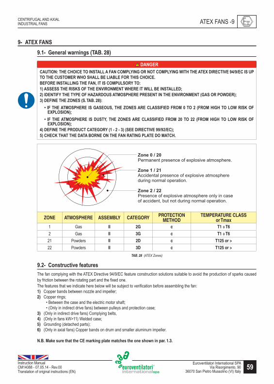
59Euroventilatori International SPAVia Risorgimento, 90
36070 San Pietro Mussolino (VI) Italy
CENTRIFUGAL AND AXIAL INDUSTRIAL FANS
Instruction Manual CM14088 - 07.05.14 - Rev.00Translation of original instructions (EN)
9- ATEX FANS9.1- �,Q,�b<�>b�QjQq=�(TAB. 28)
DANGER������'��������������������������������%���� ���������%���W�����������Z��� ��������]�������������������������� �W���������&�����&����� ������������_&��� �������������������������������� %���'�"������������ ��������������� �����W�� �����W����&������������"�������%������%��������^� ������������� ��� �������������� �����!����� ���W�� "�#"�����������^����(S. TAB. 28):
�� ��������������� �����������������^����� �������������� ���������� !� �������������W� �������EXPLOSION"�
�� ��� ������������ �� ��� ����%� ���� ^����� �� ����������� � ��� ��� ��� ��� !� ��� ����� ��� ��W� ���� ���EXPLOSI�"�
]"������������ ������������ %�!��������#"�!������ ���������������"�5) CHECK THAT THE DATA BORNE ON THE FAN RATING PLATE DO MATCH.
ZONE ATMOSPHERE ASSEMBLY CATEGORY PROTECTION METHOD
TEMPERATURE CLASSor Tmax
1 Gas II 2G c T1 ÷ T6
2 Gas II 3G c T1 ÷ T6
21 Powders II 2D c T125 or >
22 Powders II 3D c T125 or >
TAB. 28 (ATEX Zones)
9.2- �;Q=v�JVvj�,�?,bvJ�,=The fan complying with the ATEX Directive 94/9/EC feature construction solutions suitable to avoid the production of sparks caused by friction between the rotating part and the fixed one.The features that we indicate here below will be subject to verification before assembling the fan:1) \���?�����?��Q����������������������2) \���������
+����Q����������������������������������������+����������������������Z��������?��Q����������������������������
3) (Only in indirect drive fans) Complying belts,4) ���������������>�����>�����������5) �������������������������6) (Only in axial fans) Copper bands on drum and smaller aluminum impeller.
_&_��b�,�=J�,�vsbv�vs,����|b��jQq�+<bv,�|bvVs,=�vs,�;Q,�=s;>Q�jQ�par. 1.3.
ATEX FANS -9

60 Euroventilatori International SPAVia Risorgimento, 9036070 San Pietro Mussolino (VI) Italy
CENTRIFUGAL AND AXIAL INDUSTRIAL FANS
Instruction Manual CM14088 - 07.05.14 - Rev.00
Translation of original instructions (EN)
9.3- Fan / electric motor combination (TAB. 29 and TAB. 30)According to the classification of the environment in which the fan is installed, the Directive 99/92/EC indicates the suitable fan and electric motor (s. TAB. 29 and TAB. 30):
����^�� FAN ELECTRIC MOTOR0 Non applicable
1 II 2Gc
II 2G (Ex d/de)
II 2G (Ex e)
2 II 3Gc II 3G (Ex nA)
TAB. 29 (Electric motor by GAS zones)
�����^�� FAN ELECTRIC MOTOR20 Non applicable
21 II 2Dc II 2D (DIP - IP65)
22 II 3Dc II 3D* (DIP - IP55/IP65)
(*) In presence of conductive dusts, it is necessary product featuring IP65 (cat. 2D)
TAB. 30 (Electric motor by DUST zones)
9.4- ��,VbJvj;Q=�?;�����Z�?bQ=
DANGER������'� ����� ������ � �� �� ��������� ������ ��� �Z������� � � ������&����%� ���� � � ����� ��� ��������� %����������������W����������_������������������������ ��������mm���������� �� ���������� ������ ��������� ��� ���� ��� ���� ���� ��� ���� ���� ������ ��� ����������� ��� ���� ��������%���&%�������_��� �������������������%���������� ��������%��������������������&��W��������������Z����� ���������������� ���� ����%�����������������%���������� ��_
9.5- �QQ,�,=Refer to the Annex delivered separately [������ ����������%��Z����������� �����\ for the installation, use, and maintenance of ATEX fans (SAXMI010).
9- ATEX FANS

61Euroventilatori International SPAVia Risorgimento, 90
36070 San Pietro Mussolino (VI) Italy
CENTRIFUGAL AND AXIAL INDUSTRIAL FANS
Instruction Manual CM14088 - 07.05.14 - Rev.00Translation of original instructions (EN)
10- DECOMMISSIONING10.1- StorageIf upon delivery the fan is not installed and is not going to be used for long time, it is necessary to store it in a safe environment, with a suitable temperature and humidity, as well as to protect it against dust. In detail, cover the bearings, shafts and electric motor. Periodically check the fan and, in case of roller bearings, let it rotate by hand every week. Do not store it close to machines producing vibrations.
10.2- DemolitionUpon demolition of the fan, compulsorily comply with the provisions of the regulations in force.
Separate the parts making up the fan according to the different construction materials (plastic, copper, iron, etc.).
CAUTIONALL COMPONENTS OF THE FAN MUST COMPULSORILY BE IDENTIFIED PURSUANT TO THE DEFINITIONS OF THE [�W�������\�!�� �����W��������������"������������������ ��������������^����������� �^���������������&�����������������W�������� �������������� ������������� %�����������������THE FAN.
CAUTION����W���������� ����������� �����`�������!W���"���������&�����������������&�����������������W�������� �������������� ������������� %�����������������������_
DECOMMISSIONING -10
62 Euroventilatori International SPAVia Risorgimento, 9036070 San Pietro Mussolino (VI) Italy
CENTRIFUGAL AND AXIAL INDUSTRIAL FANS
Instruction Manual CM14088 - 07.05.14 - Rev.00
Translation of original instructions (EN)
11- SPARE PARTS11.1- ��,Q,�b<�>b�QjQq=
W� ��� ��������� ���� ����� ��%� ������������������&�� �`���������%�� ��������������� � �� ���������� �^�������� _�
DANGER�������&�������%��� &�������� ��������%������������W�������� ��������� ���� ��_
11- SPARE PARTS

63Euroventilatori International SPAVia Risorgimento, 90
36070 San Pietro Mussolino (VI) Italy
CENTRIFUGAL AND AXIAL INDUSTRIAL FANS
Instruction Manual CM14088 - 07.05.14 - Rev.00Translation of original instructions (EN)
12- TROUBLESHOOTING (TAB. 31÷TAB. 34)
12.1- ���;J~<,=s;;vjQqTAB. 31, TAB. 32, TAB. 33 and TAB. 34 outline a series of situations that may occur durign the use of the fan.
DANGER��������� �^��� ��� ��� �� ������ �� �� �� �Z��������%� ���� W� ��� �� ������ ��� ���� ����� (S. PAR. 2.2.2)������&����������������������������� ���� _
ANOMALIES CAUSES TROUBLESHOOTING
�Q=J??jVj,Qv�bj��flow rate
At normal rotation speed, it is accompanied by a power reduction for radial fans, especially for those with forward ���Z���?�������� ������������?�����]�$Q����?������ ��� ����� ��K������� ���������� ������� �����Q������Z�����blades and, in same special application cases, it may slightly increase.Wrong rotation of the electric motor. Check the electric motor rotation direction.
Wrong impeller rotation.
Check the impeller rotation direction. A radial fan rotating in reverse direction pushes in any case air in the circuit. Handy tip: If it is possible to see only a few mm of the shaft let the end of a ruler drop on the shaft. The side where it is projected indicates the rotation direction.
Decrease the belt rotation and/or sliding speed. Check the rotation speed and the belt tensioning and cleaning.
Excessive pressure drop in the circuit due to the following reasons.
Select a straight section of the air channel where the turbulence coming from upstream is minimal - preferably upstream of the fan - and using the Pitot tube establish ���� ���� KQ� ����� ����� ��� �Z����?��� ��� ����� ����]� ��������the static suction and delivery pressure values properly. The algebraic difference gives the static pressure of the ���]�_����������KQ����������Q����������������������������or greater than the design one, the greater fault is to be found more likely in the circuit than in the fan. Check the circuit sections to establish the points where these drops are excessive. This can be done by checking the static or total pressure in strategical points of the circuit.
Gates badly set. Set the gates.Two or more very near curves, obstructions or section changes or sharp deviations.
Modify moving section changes far from one another and making deviations less sharp.
The inlet or diffusion grid is excessively tight. Replace the inlet or diffusion grid.��{��������Z�������] \���������{����]Accumulation of foreign bodies inside the piping. Clean the piping.Turbulence. $�Z�������������Q���������{���]Turbulence due to a narrowing. $�Z�������������Q���������{���]Straight air relief channel whose length is less than 2,5 times its diameter. Modify the channel.
TAB. 31 (Anomalies 1)
ANOMALIES -12
64 Euroventilatori International SPAVia Risorgimento, 9036070 San Pietro Mussolino (VI) Italy
CENTRIFUGAL AND AXIAL INDUSTRIAL FANS
Instruction Manual CM14088 - 07.05.14 - Rev.00
Translation of original instructions (EN)
ANOMALIES CAUSES TROUBLESHOOTING
�Q=J??jVj,Qv�bj��flow rate
Anomalies in and/or at the fan due to the following reasons.
_��?���Z��������KQ�����������������������Q�����������fault is likely to be found in the fan and in its closest connections, although circuit errors may also affect this situation. After having checked that the rotation direction of the electric motor and of the impeller is right, proceed with the other checks as follows.
Presence of dirt or foreign bodies in the impeller. Clean the impeller.\������� ��� ���� ��������� ��������� ���� K�`�?���joints. Clean the channels.
Whirling current at suction in the same impeller rotation direction.
Mount an anti-turbulence device (e.g. a simple air separating sheet metal in the suction hood).
Sudden enlargement of the delivery piping. Modify the delivery piping.Air type more or less cold and with more or less pressure compared to the calculated data.
Verify and analyze the calculations and design and/or operation temperature.
��V,==j�,�air flow rate !,�V,==j�,�+�,==J�,�d�;+�in the circuit)
At nominal rotation speed, it causes an excessive consumption for the radial fans with forward curved blades. Power absorption increases for fans with radial output blades and for the fans with reverse blades. Power can be �������������������������`�����������������������Q������Z�����?�����]������`��������KQ������Z����������Z����an indication concerning the cause, for example up to values 10 % higher than the design values, it may indicate an "excessive estimate of the circuit pressure drop". A remarkably higher difference may indicate a major problem in the circuit. Proceed systematically.Wrong impeller rotation. Check the impeller rotation direction and its orientation.High electric motor rotation speed. Check the electric motor rotation speed.
Pulley size wrong. Check the diameter of the pulleys and the transmission ratio.
Gates and registers not properly positioned. Properly position gates and registers.Aeraulic circuit components not installed. Install and verify the circuit components.Air leaks at the testing point or in the masonry channels.
Check and close air leaks at the testing point or in the masonry channels.
Bypass gates not perfectly closed. Close the bypass gates.Unbalancing among fans working in parallel. Find the right balancing among fans working in parallel.
Excessive estimate of the circuit pressure drop.Calculate the estimate of circuit pressure drop (verify design calculations) and decrease the revolutions of the fan and/or shutter the gates or valves, if any.
TAB. 32 (Anomalies 2)
12- ANOMALIES

65Euroventilatori International SPAVia Risorgimento, 90
36070 San Pietro Mussolino (VI) Italy
CENTRIFUGAL AND AXIAL INDUSTRIAL FANS
Instruction Manual CM14088 - 07.05.14 - Rev.00Translation of original instructions (EN)
ANOMALIES CAUSES TROUBLESHOOTING
��V,==j�,�power b~=;�+vj;Q
A radial impeller with forward curved blades, an impeller with radial output blades is conveying too much air.
Shutter the suction inlet / Mount an impeller with different blades.
A radial impeller with reverse curved blades rotating in reverse direction or an impeller with wrong rotation direction rotating properly.
Verify the impeller rotation direction and/or orientation.
A pre-rotation of the air at suction in opposite direction to the fan rotation one.
Check and re-position the suction hood or verify the fan suction.
A short pitch axial fan or an axial impeller working with excessive pressure. Mount a different impeller or one with a long pitch.
An alternating current electric motor rotating below its usual rotation speed due to defects in the windings or ��������������������Q�Q���Z�����]
Check electric motor voltage or replace it.
Faults in the electric motor and/or connection. Verify the connection and/or replace the electric motor.
�bJ<v*�=vb�v
Excessive power absorption. Check power absorption.Reduced power supply voltage. Check power supply voltage.Max. relay unsuitable for starting conditions. Replace the max. relay with a suitable one.Fault of the electric motor resulting in a decrease of its peak features. Replace the electric motor.
Inadequate evaluation of the moment of inertia of fan rotating parts with reference to the selected electric motor and its type of start.
���������������������Q������������KQ����������������friction on mechanical parts.
Start voltage too low. Check power supply voltage.
�j��+J<=,=
An axial fan working in the initial area of its operation feature under stall conditions. Check the check and/or piping.
Most of the other type of fans working close to null KQ��������������] Check the piping and fan revolutions.
Fluctuations of the fan in parallel arrangement. Optimize the connection piping.Clogging or bad connection at suction creates instable conditions at air inlet (e.g. vortex). Remove any clogging and/or bad connections.
Alternating disconnection and re-connection of the KQ�������Q�����������Z��������������] Verify the circuit.
TAB. 33 (Anomalies 3)
ANOMALIES -12

66 Euroventilatori International SPAVia Risorgimento, 9036070 San Pietro Mussolino (VI) Italy
CENTRIFUGAL AND AXIAL INDUSTRIAL FANS
Instruction Manual CM14088 - 07.05.14 - Rev.00
Translation of original instructions (EN)
ANOMALIES CAUSES TROUBLESHOOTING
;j=,
_���������������������������������������������������������?��������Q����������������Z���?��������������?��]�It can be generated as noise due to air, the mechanical parts or pick-up noise or to a combination of these three. Noise due to air can increase due to clogging close to the fan suction or delivery. More often, noise is due to a wrong selection of the fan. This latter condition can be solved only by replacing the fan with a quieter one (usually ��Z���������������������������Q�����������?��������������{������������������������������?����]
Mechanical Q;j=,
Friction of moving parts. Check the impeller movement and, if necessary, clean it.
Wrong selection of bearings. Replace the bearings.
Sheet metal vibrations (protections). Check the tightening of the sheet metals (protections). Reinforce the structure.
�<,Vv�jV�Q;j=,Eccentricity between electric motor and stator.
Verify, check and/or replace the electric motor.Faults or porosity in the rotor die casts.Vibrations in winding.
�j~�bvj;Q=
Vibrations at an unacceptable level may result from unbalances or unsuitable support structure or by a combination of the two. When the natural frequency of a support structure is close to the one of the fan rotation speed, no balancing, even when accurate, can avoid vibrations. It is possible to reinforce the structure or appreciably modify its natural resonance frequency (e.g. by adding weights). In case of excessive unbalancing, refer to the fan manufacturer or to an expert in vibrations (often it is necessary to re-balance the impeller). It is advisable to install anti-vibration devices and/or vibration control/alarm systems.
Unbalances.Check the machine balancing, its anchoring to the support surface. (In case of excessive unbalancing, refer to the manufacturer).
Support structure unsuitable. Reinforce the structure or appreciably modify its natural resonance frequency using suitable weights.
Impeller unbalanced. Re-balance the impeller.TAB. 34 (Anomalies 4)
12- ANOMALIES

67Euroventilatori International SPAVia Risorgimento, 90
36070 San Pietro Mussolino (VI) Italy
CENTRIFUGAL AND AXIAL INDUSTRIAL FANS
Instruction Manual CM14088 - 07.05.14 - Rev.00Translation of original instructions (EN)
13- ANNEXES
13.1- ��Qv,Qd,d�J=,�?;��vs,�dj??,�,Qv�|;d,<=
DANGER������'�&������������������������ �������������������������� %������W���������%�W��������INTENDED USE (S. PAR. 3.7)������W����� �����&�%��� �����&������ ��� �����(S. PAR. 3.10)�������TO ALL MODELS.
Series �������������� ���� ���� ���� ���� �
INTENDED USE
Suction of even very dusty air.Used for pneumatic conveyances; in cement factories; for feeding air for cupolas; in foundries and oil burners; in mills; ���������������� ����������� ��� ���������������������� ��������� �������������������������������������������high pressures are required.���������������������������� ����������������������������������������������������
Series ���V����V����V��� �V��� �V��� �V��� �V��� �V
INTENDED USE
Suction of even very dusty air.Used for pneumatic conveyances; in cement factories; for feeding air for cupolas; in foundries and oil burners; in mills; ���������������� ����������� ��� ���������������������� ��������� �������������������������������������������high pressures are required.���������������������������� ��� �������������������!����������������������� For temperatures of the ������������������������������������������!����������������������������������"������������������#�������������������auger; besides, the fan is painted with a special aluminum paint suitable for high temperatures.
Series �� ������ ������ ������ ������ ���
INTENDED USE
Suction of even very dusty air.Used for pneumatic conveyances; in cement factories; for feeding air for cupolas; in foundries and oil burners; in mills; ���������������� ����������� ��� ���������������������� ��������� �������������������������������������������high pressures are required.���������������������������� �������������������!���������"���������������������
Series �� ����� ����� ��
INTENDED USE
Suction of clean and dusty air.Used for providing oxygen to impure waters; for pneumatic conveyances; in cement factories; in mills; in pasta making factories; in dye works (for quick drying wool); in ceramic factories (for the pneumatic cleaning of the rooms); in ��� ���������������������� ��������� ��������������������������������������������������������������������$�����%���������������������������� �������������������������
Series ��������� ��
INTENDED USE
Suction of very dusty air containing various types of suspended materials. Used in carpentry shops for transporting saw dust and wooden chips, ���������#$�����������, in mechanical processing factories for drawing in metal chips and burrs; for pneumatic transports in cement factories, ceramic factories, mills, fodder factories, tanneries, foundries, in textile and chemical factories and, in general, for all those applications where it is necessary to convey harmful air with low and medium pressure.&�����������������'����������������������������������������������������For higher temperatures, it is necessary to modify the construction of the fan.
ANNEXES -13

68 Euroventilatori International SPAVia Risorgimento, 9036070 San Pietro Mussolino (VI) Italy
CENTRIFUGAL AND AXIAL INDUSTRIAL FANS
Instruction Manual CM14088 - 07.05.14 - Rev.00
Translation of original instructions (EN)
Series EUc
INTENDED USE
Suction of dusts, fumes, granulates, sawdust or wood shavings of minimum size and materials in general mixed with air, ���������#$�����������.Used in carpentry shops, mechanical processing factories, cement factories, ceramic factories, tanneries, foundries, in milling and chemical factories, and for all those applications where it is necessary to convey harmful air with MAX. temperature of 90 °C.&��������������������������������������������!����������������������������������"������������������#���������������and auger; besides, the fan is painted with a special aluminum paint suitable for high temperatures.
Series EUMc
INTENDED USE
Used in drying plants, pneumatic transports, fume extraction, forced draught in the chimneys, transport of granulates and sawdust mixed with air, ���������#$�����������.Used in carpentry shops, mechanical processing factories, cement factories, ceramic factories, tanneries, foundries, in milling and chemical factories, and for all those applications where it is necessary to convey harmful air with MAX. temperature of 90 °C.&��������������������������������������������!����������������������������������"������������������#���������������and auger; besides, the fan is painted with a special aluminum paint suitable for high temperatures.
Series ��������
INTENDED USE
Suction of very dusty air containing various types of suspended materials.Used in carpentry shops for transporting sawdust and wood shavings; in tanneries for conveying skin trimmings and shaving; in bookbinding factories for conveying paper trimmings; in textile factories for transporting waste and long "#�������������� ����� ��������� ���������������������������������������������������������������������������������#��������as paper tearing device; etc.*��������������������������������
Series �����`
INTENDED USE
Suction of very dusty air containing various types of suspended materials. ��������������������������Z��������Q���������Q�����Z�������������������������������������������������������Z����������������������������������������������������������]�s,�v,|+,�bvJ�,�;?�vs,�d�b>Q�jQ��Jjd�|J=v�Q;v�,�V,,d������_
Series TTRc
INTENDED USE ���������Q�����Z������������������������{?�������������]Used in carpentry shops, tanneries, bookbinding factories and paper mills.
Series � V��
INTENDED USE
Suction of dusts, fumes, granulates, sawdust or wood shavings of minimum size and materials in general mixed with air, ���������#$�����������.Used in carpentry shops, mechanical processing factories, cement factories, ceramic factories, tanneries, foundries, milling and chemical factories, and for all those applications where it is necessary to convey harmful air with MAX. temperature of 90 °C.������������������������������[\����������"��[\����������������������������{�����������������?��Q��������������������?��������������������������Q��������������������������������?����������������������]
Series ��V���V���V
INTENDED USE
Suction of very dusty air containing various types of suspended materials.�������������������������������������Q���������Q�����Z������������������������Z����������������������������Z��������?�?���������������������Z��������������������������`����������������������������Q�������������{?�������������������������������������������������������������������������������������������������������?������������������������Z��������]For maximum air temperature of 90 °C (250 °C with cooling fan).
13- ANNEXES

69Euroventilatori International SPAVia Risorgimento, 90
36070 San Pietro Mussolino (VI) Italy
CENTRIFUGAL AND AXIAL INDUSTRIAL FANS
Instruction Manual CM14088 - 07.05.14 - Rev.00Translation of original instructions (EN)
Series MPRc
INTENDED USE
Suction of very dusty air containing various types of suspended materials.Used in carpentry shops for transporting sawdust and wooden shavings, ���������#$�����������, in mechanical ��������� ��������� ��� ���Q���� ��� ������ ����� ���� ?������ ��� ��������� ��������� ��� ������� ���������� ��������factories, mills, fodder factories, tanneries, foundries, in textile and chemical factories and, in general, for all those applications where it is necessary to convey harmful air with low and medium pressure.�s,�v,|+,�bvJ�,�;?�vs,�d�b>Q�jQ��Jjd�|J=v�Q;v�,�V,,d�������!#������>jvs�V;;<jQq�?bQ"_
Series &��&� �&�
INTENDED USE
Suction of clean or slightly dusty air. ��������Z��������������������������������������������������������������Q������������������������������������������noxious gases.�s,� v,|+,�bvJ�,� ;?� vs,� V;Q�,*,d� �Jjd� |J=v� Q;v� ,�V,,d� ��� ��� bQd� ���� ��� >jvs� V;;<jQq� ?bQ_ For higher temperatures, it is necessary to modify the construction of the fan.
Series &�V�&� V
INTENDED USE
Suction of clean or slightly dusty air.Used for ventilation systems in stables, mines and tunnels.��������������������Q��������������Z����������Z���������������������������������?������������������������Q�����������������������������`������������������������������������������������������Q����������������������and noxious gases.�;��b���Z_�bj��v,|+,�bvJ�,�;?�������>jvs�<;>�+�,==J�,]��������Z�����K�������������������������������[\����������"��[\����������������������{�����������������?��Q������������������]
Series BPRDc
INTENDED USE
Suction of great volumes of clean or slightly dusty air.��������������������������������Z����������Z����������`�����������Z������������������������������������������Q����������������������������?����������]�;��b���Z_�bj��qb=�bQd�?J|,�v,|+,�bvJ�,�;?�������>jvs�<;>�+�,==J�,.
Series �����������
INTENDED USE
Suction of fume, as well as of stale, dusty and humid air in foundries, cement factories, paper mills, and carpentry shops.��������������?�����������������������Q���������?��������������������Q������������������������������Q�����etc. and, in general, where it is necessary to transport big volumes of air with low pressures.W;��jQq�v,|+,�bvJ�,�����_����������Z_�������_�
Series ��V
INTENDED USE
Suction of fume, as well as of stale, dusty and humid air.����������������?����Q������������������������?�����������������������������������������{�����������������������construction with impeller made of anti-spark material and electric motor anchored externally to the fan.W;��jQq�v,|+,�bvJ�,�����_����������Z_��$����_
Series ���
INTENDED USE
Suction of stale air, fume, and vapors of environments.Used for ventilating workshops, foundries, cement factories tanneries, carpentry shops, as well as chemical, mechanical �����������������������������Q������������������?�������Z����������Q��������������������]W;��jQq�v,|+,�bvJ�,�����_����������Z_�������_
ANNEXES -13

70 Euroventilatori International SPAVia Risorgimento, 9036070 San Pietro Mussolino (VI) Italy
CENTRIFUGAL AND AXIAL INDUSTRIAL FANS
Instruction Manual CM14088 - 07.05.14 - Rev.00
Translation of original instructions (EN)
13.2- Air noise (TAB. 35÷TAB. 45)The following tables show the data related to air noise of the various fan models.
13.2.1- ;j=,'� q,Q,�b<� jQ?;�|bvj;Q� (Ref. EN ISO 3744, EN ISO 3746 and ISO 13347) (securities TAB. 35 ÷ TAB. 45)
Sound power level LwAIt is the average value of the sound power level in dB(A) (weighted value according to the scale A) radiated into the environment by the fan though the inlet and outlet ducts. The value refers to air conveyed with a density of 1,226 kg/m3, at the maximum allowable rotation speed of the impeller and during operation at the optimal curve point._���������������������������������������������{������������������������������������������������������������������������������?�����K������������������������K��������������������]Moreover, the value of the background noise of the installation environment is deemed neglectable.
Sound pressure level LpAIt is the average of the temporal average values of the sound pressure radiated into the environment by the fan through the inlet and outlet ducts. The pressure values are recorded on the measurement surface enveloping the fan (parallelepiped measurement surface).Experimentally, acoustic pressure measurements are obtained by 8 microphone stations located on the reference surface at a height equal to the fan rotation axis (FIG. 35).The pressure value is expressed in dB(A) (weighted value according to the scale A).The value refers to air conveyed with a density of 1,226 kg/m3, at the maximum allowable rotation speed of the impeller and during operation at the optimal curve point.The given values refer to a measuring distance of one meter._���������������������������������������������{������������������������������������������������������������������������������?�����K������������������������K��������������������]The value of the background noise of the installation environment is deemed neglectable.
FIG. 35 (Aircraft noise)
13- ANNEXES

71Euroventilatori International SPAVia Risorgimento, 90
36070 San Pietro Mussolino (VI) Italy
CENTRIFUGAL AND AXIAL INDUSTRIAL FANS
Instruction Manual CM14088 - 07.05.14 - Rev.00Translation of original instructions (EN)
Legend:
�& dB(A) ��80 ��&� weighted sound pressure level at output A at the places of work
�&� 80 < dB(A) ��90 �Q�& weighted sound power level A issued by the machine
x= dB(A) > 90
High pressure, direct drive centrifugal fans - Series:
Electric motor Model APE APF APG APRF APRG APRH APRI APRL
Lp Lw Lp Lw Lp Lw Lp Lw Lp Lw Lp Lw Lp Lw Lp Lw
2 poles
351/2 � �401/2 � �451/2 � �501/2 � � � x � x � x561/2 � � � x � x � x � x631/2 � x � x � x � x � x x x x x x x711/2 � x � x � x � x � x x x x x x x801/2 � x � x x x � x x x x x x x x x901/2 � x x x x x � x x x x x x x1001/2 x x x x x x x x1121/2 x x x x
4 poles
631/2 � �711/2 � � � x801/2 � � � x � x � x901/2 � � � x � x � x1001/2 � x � x � x � x1121/2 � x � x
TAB. 35 (Centrifugal fans - models APE, APF, APG, APRF, APRG, APRH, APRI, APRL)
High pressure, double stage, direct drive centrifugal fans - Series:
Model APRED APRFD APRGDLp Lw Lp Lw Lp Lw
631/2 � x � x711/2 � x � x801/2 � x � x901/2 � x x x x x
1001/2 x x x x x x1121/2 x x x x
TAB. 36 (Centrifugal fans - models APRED, APRFD, APRGD)
ANNEXES -13
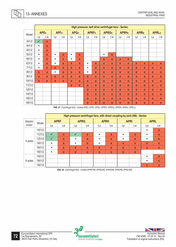
72 Euroventilatori International SPAVia Risorgimento, 9036070 San Pietro Mussolino (VI) Italy
CENTRIFUGAL AND AXIAL INDUSTRIAL FANS
Instruction Manual CM14088 - 07.05.14 - Rev.00
Translation of original instructions (EN)
High pressure, belt drive centrifugal fans - Series:
Model APEc APFc APGc APRFc APRGc APRHc APRIc APRLcLp Lw Lp Lw Lp Lw Lp Lw Lp Lw Lp Lw Lp Lw Lp Lw
351/2 � x401/2 � x451/2 � x501/2 � x � x � x � x561/2 � x � x � x x x x x631/2 � x � x x x � x x x x x x x x x711/2 � x x x x x � x x x x x x x x x801/2 x x � x x x � x x x x x x x x x901/2 x x x x x x x x x x x x x x x x
1001/2 x x x x x x x x x x x x x x x x1121/2 x x x x x x x x x x x x1251/2 x x x x x x x x x x1401/2 x x x x x x x x x x1601/2 x x x x x x x x x x1801/2 x x x x x x x x x x
TAB. 37 (Centrifugal fans - models APEc, APFc, APGc, APRFc, APRGc, APRHc, APRIc, APRLc)
High pressure centrifugal fans, with direct coupling by joint (N8) - Series:
Electric motor Model APRF APRG APRH APRI APRL
Lp Lw Lp Lw Lp Lw Lp Lw Lp Lw
4 poles
1001/2 � x1121/2 � x � x � x � x � x1251/2 � x � x � x � x � x1401/2 � x � x � x x x x x1601/2 � x x x x x x x x x1801/2 � x x x x x x x
6 poles1401/2 � x1601/2 � x1801/2 x x
TAB. 38 (Centrifugal fans - models APRF/N8, APRG/N8, APRH/N8, APRI/N8, APRL/N8)
13- ANNEXES

73Euroventilatori International SPAVia Risorgimento, 90
36070 San Pietro Mussolino (VI) Italy
CENTRIFUGAL AND AXIAL INDUSTRIAL FANS
Instruction Manual CM14088 - 07.05.14 - Rev.00Translation of original instructions (EN)
Medium pressure, direct drive centrifugal fans - Series:
Electric motor Model EU EUM MPR TR TPA �` TF TG TH
Lp Lw Lp Lw Lp Lw Lp Lw Lp Lw Lp Lw Lp Lw Lp Lw Lp Lw
2 poles
221/2 � � � �251/2 � � � �281/2 � � � �311/2 � � � � � x351/2 � � � � � � � x401/2 � x � x � � � � � x � � � x451/2 � x � x � � � � � x � x � x501/2 � x � x � x � � � x � x � x561/2 � x � x � x � x � x � x � x631/2 � x � x � x x x x x711/2 x x x x801/2 x x x x
4 poles
631/2 � � � � � � � � � x711/2 � � � � � � � x � x801/2 � x � x � � � x � x � x � x901/2 � x � x � x � x � x � x � x1001/2 � x � x � x � x � x � x1121/2 � x � x � x x x x x1251/2 � x � x1401/2 x x
6 poles 1401/2 � xTAB. 39 (Centrifugal fans - models EU, EUM, MPR, TR, TPA, TQ, TF, TG, TH)
ANNEXES -13

74 Euroventilatori International SPAVia Risorgimento, 9036070 San Pietro Mussolino (VI) Italy
CENTRIFUGAL AND AXIAL INDUSTRIAL FANS
Instruction Manual CM14088 - 07.05.14 - Rev.00
Translation of original instructions (EN)
Medium pressure, belt drive centrifugal fans - Series:
Model EUc EUMc TRc TTRc TFc TGc THc MPRcLp Lw Lp Lw Lp Lw Lp Lw Lp Lw Lp Lw Lp Lw Lp Lw
221/2 � �251/2 � �281/2 � x311/2 � x � x351/2 � x � x � x401/2 � x � x � x � x � x � x451/2 � x � x � x � x � x � x501/2 � x � x � x � x � x � x � x561/2 � x � x � x � x � x x x � x � x631/2 � x � x � x � x � x � x � x711/2 � x � x � x x x � x � x x x801/2 � x � x � x x x � x � x x x901/2 � x � x � x x x � x x x x x
1001/2 � x � x � x x x x x x x x x1121/2 � x x x � x x x x x x x1251/2 � x x x x x x x1401/2 � x x x x x x x1601/2 � x x x x x x x1801/2 x x x x x x2001/2 x x x x x x
TAB. 40 (Centrifugal fans - models EUc, EUMc, TRc, TTRc, TFc, TGc, THc, MPRc)
Low pressure, belt drive axial fans - Series:
Model ��cLp Lw
400 � x500 � x630 � x710 � x800 � x900 � x
1000 � x1120 � x1250 � x1400 � x
TAB. 41 (Axial fans models EVc)
13- ANNEXES

75Euroventilatori International SPAVia Risorgimento, 90
36070 San Pietro Mussolino (VI) Italy
CENTRIFUGAL AND AXIAL INDUSTRIAL FANS
Instruction Manual CM14088 - 07.05.14 - Rev.00Translation of original instructions (EN)
Low pressure, direct drive axial fans - Series:
Electric motor Model ������������!�^���" ������������!�^���" ���
Lp Lw Lp Lw Lp Lw
2 poles
315 � � � x355 � � � x400 � x � x450 � x500 � x560 � x630 x x
4 poles
315 � � � �355 � � � �400 � � � �450 � � � �500 � � � �560 � � � x � �630 � � � x � �710 � � � x � �800 � x � x � x900 � x � x
1000 � x1120 � x
6 poles
630 � � � � � �710 � � � � � �800 � � � x � �900 � � � x � �
1000 � � � x � �1120 � x � x1250 � x1400 � x
8 poles1120 � � � x1250 � x � x1400 � x � x
TAB. 42 (Axial fans models EVP, EVF, EVL, EVT)
ANNEXES -13

76 Euroventilatori International SPAVia Risorgimento, 9036070 San Pietro Mussolino (VI) Italy
CENTRIFUGAL AND AXIAL INDUSTRIAL FANS
Instruction Manual CM14088 - 07.05.14 - Rev.00
Translation of original instructions (EN)
Low pressure, direct drive centrifugal fans - Series:
Electric motor Model BP BPR BT
Lp Lw Lp Lw Lp Lw
2 poles
161 � �201 � �221 � x251 � x281311351 � x401 � x451 � x501 � x
4 poles
161 � �201 � �221 � �251 � �281 � �311 � �351 � � � � � �401 � x � � � �451 � x � � � �501 � x � � � �561 � � � x631 � x � �711 � x801 � x901 � x1001 � x
TAB. 43 (Centrifugal fans - models BP, BPR, BT)
13- ANNEXES

77Euroventilatori International SPAVia Risorgimento, 90
36070 San Pietro Mussolino (VI) Italy
CENTRIFUGAL AND AXIAL INDUSTRIAL FANS
Instruction Manual CM14088 - 07.05.14 - Rev.00Translation of original instructions (EN)
Low pressure, direct drive centrifugal fans - Series:
Electric motor Model
BP BPR BTLp Lw Lp Lw Lp Lw
6 poles
311 � �351 � �401 � �451 � x501 � � � � � �561 � � � �632 � � � �711 � �801 � x901 � x1001 � x1121 � x1251 � x1401 � x
8 poles 631 � �TAB. 44 (Centrifugal fans - models BP, BPR, BT)
ANNEXES -13

78 Euroventilatori International SPAVia Risorgimento, 9036070 San Pietro Mussolino (VI) Italy
CENTRIFUGAL AND AXIAL INDUSTRIAL FANS
Instruction Manual CM14088 - 07.05.14 - Rev.00
Translation of original instructions (EN)
Low pressure, belt drive centrifugal fans - Series:
Model BPRc BPc BPRDcLp Lw Lp Lw Lp Lw
251/2 �281/2 �311/2 � �351/2 � �401/2 � x � �451/2 � x � �501/2 � x � � � x561/2 � x � � � x631/2 � x � x � x711/2 � x � x � x801/2 � x � x � x901/2 � x � x � x
1001/2 � x � x � x1121/2 � x � x1251/2 x x � x1401/2 x x � x1601/2 x x1801/2 � x2001/2 � x
TAB. 45 (Centrifugal fans - models BPc, BPRc, BPRDc)
13- ANNEXES

79Euroventilatori International SPAVia Risorgimento, 90
36070 San Pietro Mussolino (VI) Italy
CENTRIFUGAL AND AXIAL INDUSTRIAL FANS
Instruction Manual CM14088 - 07.05.14 - Rev.00Translation of original instructions (EN)
13.3- Weights (TAB. 46÷TAB. 63)
Legend:
�& ��25 kg \�&�\��� ���&����� ����&��Q������?���
�&� 25 < kg ��75 ��&�_������ ��&���� ����&��������?���
o& 75 < kg ��150 ��&����� ��&�\�������������Z��� �&�������
x&� kg >150 ��&�\�� \Z�&�$�\��Z�� &�>�����������@�����������
High pressure, direct drive centrifugal fans - Series:
Electric motor Model APE APF APG APRF
C G S V C G S B V C G S B V C G S B V
2 poles
351/2 � � � �401/2 � � � �451/2 � � � �501/2 � � � � � � � � � � � �561/2 � � � � � � � � � � � o631/2 � � � � � � � � � � � x � � � o711/2 � � � o � � � o o o � x � � � o801/2 � � � o o o � x o o � x o o � x901/2 � � � x o x � � x x x � � x o o � � x1001/2 x x � � x1121/2 x x o � x
4 poles
631/2711/2801/2 � � � x901/2 o o � � x1001/2 o x � � x1121/2 x x o � x
TAB. 46 (Centrifugal fans - models APE, APF, APG, APRF)
ANNEXES -13

80 Euroventilatori International SPAVia Risorgimento, 9036070 San Pietro Mussolino (VI) Italy
CENTRIFUGAL AND AXIAL INDUSTRIAL FANS
Instruction Manual CM14088 - 07.05.14 - Rev.00
Translation of original instructions (EN)
High pressure, direct drive centrifugal fans - Series:
Electric motor Model APRG APRH APRI APRL
C G S B V C G S B V C G S B V C G S B V
2 poles
351/2401/2451/2501/2 � � � �561/2 � � � � � � � o631/2 � � � o � � � o o � � x o o � � x711/2 o � � x o o � x o o � x o x � � x801/2 o o � x o o � x o o � x x x o � x901/2 o x � � x o x � � x o x � � x
1001/2 x x o � x o x � � x x x o � x1121/2 x x o � x
4 poles
631/2 � � � x711/2 o � � x o � � x801/2 o o � x o o � x o o � x901/2 o o � � x o o � � x o o � � x
1001/2 o x � � x o x � � x x x o � x1121/2 x x o � x
TAB. 47 (Centrifugal fans - models APRG, APRH, APRI, APRL)
High pressure, double stage, direct drive centrifugal fans - Series:
Model APRED APRFD APRGDC1 C2 G1 G2 B1 B2 S T V C1 C2 G1 G2 B1 B2 S T V C1 C2 G1 G2 B1 B2 S T V
631/2 � � � � � � x � � � � � � x711/2 � � � � � � x o o � � o � x801/2 � � � � o � x o o o o o o x901/2 o o � � � � o � x x x o o � � x o x x x x x � � x x x
1001/2 o o o o � � x o x x x x x � � x x x x x x x � � x x x1121/2 x x x x � � x x x x x x x � � x x x
TAB. 48 (Centrifugal fans - models APRED, APRFD, APRGD)
13- ANNEXES

81Euroventilatori International SPAVia Risorgimento, 90
36070 San Pietro Mussolino (VI) Italy
CENTRIFUGAL AND AXIAL INDUSTRIAL FANS
Instruction Manual CM14088 - 07.05.14 - Rev.00Translation of original instructions (EN)
High pressure, belt drive centrifugal fans - Series:
Model APEc APFc APGc APRFcC G S B Su V C G S B Su V C G S B Su V C G S B Su V
351/2 � � � � �401/2 � � � � �451/2 � � � � �501/2 � � � � � � � � � � � � � � o561/2 � � � � � � � � � o � � � � o631/2 � � � � � � � � � o � � � � x � � � � o711/2 � � � � o � � � � x o � � � x � � � � o801/2 � � � � o o � � � x o o � � x � � � � x901/2 � � � � x o o � � � x o o � � � x o o � � � x
1001/2 � o � � � x o x � � � x x x � � x o o � � � x1121/2 x x � � x x x � � � x1251/2 x x o � � x1401/2 x x o � x1601/2 x x o � x1801/2 x x o � x
TAB. 49 (Centrifugal fans - models APEc, APFc, APGc, APRFc)
High pressure, belt drive centrifugal fans - Series:
Model APRGc APRHc APRIc APRLcC G S B Su V C G S B Su V C G S B Su V C G S B Su V
351/2401/2451/2501/2 � � � � o561/2 � � � � o � � � � o631/2 � � � � o � � � � x � � � � x � � � � � x711/2 � � � � x o � � � x o o � � x o o � � � x801/2 o � � � x o o � � x o o � � � x o o � � � x901/2 o o � � � x o o � � � x o x � � � x x x � � x
1001/2 x x � � x x x � � x x x � � x x x � � x1121/2 x x � � x x x � � x x x � � x x x � � x1251/2 x x � � x x x o o x x x o o x x x o o x1401/2 x x o o x x x o o x x x o o x x x o o x1601/2 x x o o x x x o o x x x x o x x x x o x1801/2 x x x o x x x x x x x x x x x x x x x x
TAB. 50 (Centrifugal fans - models APRGc, APRHc, APRIc, APRLc)
ANNEXES -13

82 Euroventilatori International SPAVia Risorgimento, 9036070 San Pietro Mussolino (VI) Italy
CENTRIFUGAL AND AXIAL INDUSTRIAL FANS
Instruction Manual CM14088 - 07.05.14 - Rev.00
Translation of original instructions (EN)
High pressure centrifugal fans, with direct coupling by joint (N8) - Series:
Electric motor Model APRF APRG APRH APRI APRL
C G B Su V C G B Su V C G B Su V C G B Su V C G B Su V
4 poles
1001/2 x x o � x1121/2 x x o � x x x o � x x x o � x x x o � x x x o � x1251/2 x x o � x x x o � x x x o � x x x o � x x x x � x1401/2 x x o � x x x o � x x x o � x x x x � x x x x o x1601/2 x x x � x x x x � x x x x o x x x x o x x x x o x1801/2 x x x � x x x x o x x x x o x x x x o x
6 poles1401/2 x x x o x1601/2 x x x o x1801/2 x x x o x
TAB. 51 (Centrifugal fans - models APRF/N8, APRG/N8, APRH/N8, APRI/N8, APRL/N8)
Medium pressure, direct drive centrifugal fans - Series:
Electric motor Model EU EUM MPR TR
C G S B V C G S B V C G S B V C G S B V
2 poli
221/2 � � � � �251/2 � � � � �281/2 � � � � �311/2 � � � � � � � � � �351/2 � � � � � � � � � � � � � � �401/2 � � � � � � � � � � � � � � � � � � � �451/2 � � � � � � � � � o � � � � � � � � � �501/2 � � � � o � � � � o � � � � � � � � � o561/2 � � � � o � � � � o � � � � o � � � � o631/2 � o � � x � � � � o
4 poli
631/2 � � � � o � � � � x � � � � o711/2 o o � � x o o � � x o o � � x801/2 x o � x x o � x x o � x901/2 x o � x x x � x x x � x
1001/2 x o � x x x � x x x � x1121/2 x o o x x x � x x x o x1251/2 x x o x x x o x1401/2 x x o x x x o x
TAB. 52 (Centrifugal fans - models EU, EUM, MPR, TR)
13- ANNEXES

83Euroventilatori International SPAVia Risorgimento, 90
36070 San Pietro Mussolino (VI) Italy
CENTRIFUGAL AND AXIAL INDUSTRIAL FANS
Instruction Manual CM14088 - 07.05.14 - Rev.00Translation of original instructions (EN)
Medium pressure, direct drive centrifugal fans - Series:
Electric motor Model BP BPR BT TPA
C G S B V C G S B V Cv BaI BaS G R V C G S B V
2 poles
161/2 � � � � �201/2 � � � � �221/2 � � � � � � � � � �251/2 � � � � � � � � � �281/2 � � � � �311/2 � � � � �351/2 � � � � � � � � � �401/2 � � � � � � � � � �451/2 � � � � o � � � � �501/2 � � � � o
4 poles
161/2 � � � � �201/2 � � � � �221/2 � � � � �251/2 � � � � �281/2 � � � � �311/2 � � � � �351/2 � � � � � � � � � � � � � � � �401/2 � � � � � � � � � � � � � � � �451/2 � � � � o � � � � � � � � � � �501/2 � � � � o � � � � o � � � � � �561/2 � � � � o � � � � � �631/2 � � � � o711/2 o o � x801/2 o o � x901/2 x x � x1001/2 x x � x
TAB. 53 (Centrifugal fans - models BP, BPR, BT, TPA)
ANNEXES -13

84 Euroventilatori International SPAVia Risorgimento, 9036070 San Pietro Mussolino (VI) Italy
CENTRIFUGAL AND AXIAL INDUSTRIAL FANS
Instruction Manual CM14088 - 07.05.14 - Rev.00
Translation of original instructions (EN)
Medium pressure, direct drive centrifugal fans - Series:
Electric motor Model
BP BPR BT TPAC G S B V C G S B V Cv BaI BaS G R V C G S B V
6 poles
311/2 � � � � �351/2 � � � � �401/2 � � � � �451/2 � � � � �501/2 � � � � o � � � � o � � � � � �561/2 � � � � o � � � � o � � � � � �632/2 � � � � o � � � � � o711/2 o o � � x801/2 o o � � x901/2 x x � x
1001/2 x x � x1121/2 x x o x1251/2 x x o x1401/2 x x o x
8 poles 631/2 � � � � � oTAB. 54 (Centrifugal fans - models BP, BPR, BT, TPA)
�,djJ|�+�,==J�,�dj�,Vv�d�j�,�V,Qv�j?Jqb<�?bQ=����,�j,='
Electric motor Model �` TF TG TH
C G S B V C G S B V C G S B V C G S B V
2 poles
401/2 � � � � � � � � �451/2 � � � � � � � � �501/2 � � � � � � � � � � � � o561/2 � � � � � � � o � � � � o631/2 � � � o � � � o � o � � x711/2 � � � o � � � x801/2 � � � x o o � x
4 poles
631/2 � � � � o � � � � x711/2 � � � � o o o � x801/2 � � � � x � � � o � � � x o o � x901/2 o o � � x � o � � x o o � � x x x � x
1001/2 o o � � x o o � � x x x � x1121/2 o o � � x x x � x
TAB. 55 (Centrifugal fans - models TQ TF, TG, TH)
13- ANNEXES

85Euroventilatori International SPAVia Risorgimento, 90
36070 San Pietro Mussolino (VI) Italy
CENTRIFUGAL AND AXIAL INDUSTRIAL FANS
Instruction Manual CM14088 - 07.05.14 - Rev.00Translation of original instructions (EN)
Medium pressure, belt drive centrifugal fans - Series:
Model EUc EUMc TRcC G S B Su V C G S B Su V C G S B Su V
221/2 � � � � � �251/2 � � � � � �281/2 � � � � � �311/2 � � � � � � � � � � � �351/2 � � � � � � � � � � � �401/2 � � � � � o � � � � � o � � � � � �451/2 � � � � � o � � � � � o � � � � � o501/2 � � � � � o � � � � � o � � � � � o561/2 � � � � � x � � � � � o � � � � � x631/2 � � � � � x � � � � � x � � � � � x711/2 o o � � x o o � � x o o � � x801/2 x o � � x x o � � x o o � � x901/2 x x � � x x x � � x x o � � x
1001/2 x x � � x x x � � x x x � � x1121/2 x x o � x x x � � x x x o � x1251/2 x x o � x x x o o x x x o o x1401/2 x x o o x x x o o x x x o o x1601/2 x x x o x x x x o x x x x o x1801/2 x x x o x x x x x x x x x x x2001/2 x x x x x x x x x x x x x x x
TAB. 56 (Centrifugal fans - models EUc, EUMc, TRc)
Medium pressure, belt drive centrifugal fans - Series:
ModelTTRc TFc TGc
C G S B Su V C G S B Su V C G S B Su V401/2 � � � � �451/2 � � � � �501/2 � � � � � � � � � �561/2 � � � � � x � � � � o � � � � o631/2 � � � � � x � � � � o � � � � o711/2 o o � � x � � � � o � � � � x801/2 x o � � x � � � � x o � � � x901/2 x x � � x o o � � � x o o � � � x
1001/2 x x � � x o o � � � x x x � � � x1121/2 x x o � x x x � � � x1251/2 x x o o x1401/2 x x o o x1601/2 x x x o x
TAB. 57 (Centrifugal fans - models TTRc, TFc, TGc)
ANNEXES -13

86 Euroventilatori International SPAVia Risorgimento, 9036070 San Pietro Mussolino (VI) Italy
CENTRIFUGAL AND AXIAL INDUSTRIAL FANS
Instruction Manual CM14088 - 07.05.14 - Rev.00
Translation of original instructions (EN)
Medium pressure, belt drive centrifugal fans - Series:
Model THc BPRc BPcC G S B Su V C G S B Su V C G S B Su V
221/2251/2 � � � � � �281/2 � � � � � �311/2 � � � � � �351/2 � � � � � �401/2 � � � � � o � � � � � o � � � � � o451/2 � � � � � o � � � � � o � � � � � o501/2 � � � � � o � � � � � o � � � � � o561/2 � � � � � x � � � � � x � � � � � x631/2 � � � � � x � � � � � x � � � � � x711/2 o o � � x o o � � � x o o � � � x801/2 x o � � x o o � � � x o o � � � x901/2 x x � � x x x � � x x x � � x
1001/2 x x � � x x x � � x x x � � x1121/2 x x o � x x x o � x1251/2 x x o � x1401/2 x x o o x1601/2 x x x o x1801/2 x x x o x2001/2 x x x x x
TAB. 58 (Centrifugal fans - models THc, BPRc, BPc)
Low pressure, belt drive axial fans - Series:
Model ��cT G Su V
400 � � � �500 � � � �630 � � � �710 � � � o800 � � � o900 o � � o
1000 o � � x1120 o � � x1250 x � � x1400 x � � x
TAB. 59 (Axial fans models EVc)
13- ANNEXES

87Euroventilatori International SPAVia Risorgimento, 90
36070 San Pietro Mussolino (VI) Italy
CENTRIFUGAL AND AXIAL INDUSTRIAL FANS
Instruction Manual CM14088 - 07.05.14 - Rev.00Translation of original instructions (EN)
Low pressure, direct drive axial fans - Series:
Electric motor Model �����^��� �����^��� �����^��� �����^��� �����^��� �����^��� ���
T G V T G V T G V T G V T G V T G V T G Cv Ba V
2 poles
315 � � � � � � � � � � � � � � � � � �355 � � � � � � � � � � � � � � � � � �400 � � � � � � � � � � � � � � � � � �450 � � � � � �500 � � � � � �560 � � � � � �630 � � � � � o
4 poles
315 � � � � � � � � � � � � � � � � � �355 � � � � � � � � � � � � � � � � � �400 � � � � � � � � � � � � � � � � � �450 � � � � � � � � � � � � � � � � � �500 � � � � � � � � � � � � � � � � � �560 � � � � � � � � � � � � � � � � �630 � � � � � � � � � � � � � � � � �710 � � � � � � � � � � � o � � � � �800 � � o � � o � � o � � o � � � � �900 � � o o � o o � x o o x1000 o � o o o x1120 o o x x o x
6 poles
630 � � � � � � � � � � � � � � � � �710 � � � � � � � � � � � � � � � � �800 � � � � � o � � � � � o � � � � �900 � � o � � o � � o o � x � � � � o1000 � � o o � x o � o o � x � � � � o1120 o � x o o x o � x o o x1250 o o x x o x1400 x o x x x x
8 poles1120 o � o o � x o � x o o x1250 o o x x o x o o x x o x1400 x o x x x x x o x x x x
TAB. 60 (Axial fans - models EVP, EVF, EVL, EVT)
ANNEXES -13

88 Euroventilatori International SPAVia Risorgimento, 9036070 San Pietro Mussolino (VI) Italy
CENTRIFUGAL AND AXIAL INDUSTRIAL FANS
Instruction Manual CM14088 - 07.05.14 - Rev.00
Translation of original instructions (EN)
Low pressure, direct drive centrifugal fans - Series:
Electric motor Model BP BPR BT
C G S B V C G S B V Cv BaI BaS G R V
2 poles
161/2 � � � � �201/2 � � � � �221/2 � � � � �251/2 � � � � �281/2311/2351/2 � � � � �401/2 � � � � �451/2 � � � � o501/2 � � � � o
TAB. 61 (Centrifugal fans - models BP, BPR, BT)
Low pressure, belt drive centrifugal fans - Series:
Electric motor
BPRc BPc BPRDcC G S B Su V C G S B Su V C G K1 K2 B1 B2 Su V
251/2 � � � � � �281/2 � � � � � �311/2 � � � � � �351/2 � � � � � �401/2 � � � � � o � � � � � o451/2 � � � � � o � � � � � o501/2 � � � � � o � � � � � o � � � � � � � x561/2 � � � � � x � � � � � x � � � � � � � x631/2 � � � � � x � � � � � x o o � � � � � x711/2 o o � � � x o o � � � x o o � � � � o x801/2 o o � � � x o o � � � x x x � � � � o x901/2 x x � � x x x � � x x x � o � � o x
1001/2 x x � � x x x � � x x x � o � � o x1121/2 x x o � x x x o x � � o x1251/2 x x o � x x x o x � � x x1401/2 x x o o x x x x x o o x x1601/2 x x x o x1801/2 x x x o x2001/2 x x x x x
TAB. 62 (Centrifugal fans - models BPRc, BPc, BPRDc)
13- ANNEXES

89Euroventilatori International SPAVia Risorgimento, 90
36070 San Pietro Mussolino (VI) Italy
CENTRIFUGAL AND AXIAL INDUSTRIAL FANS
Instruction Manual CM14088 - 07.05.14 - Rev.00Translation of original instructions (EN)
Low pressure, direct drive centrifugal fans - Series:
Electric motor Model
BP BPR BTC G S B V C G S B V Cv BaI BaS G R V
4 poles
161/2 � � � � �201/2 � � � � �221/2 � � � � �251/2 � � � � �281/2 � � � � �311/2 � � � � �351/2 � � � � � � � � � � � � � � � �401/2 � � � � � � � � � � � � � � � �451/2 � � � � o � � � � � � � � � � �501/2 � � � � o � � � � o � � � � � �561/2 � � � � o � � � � � �631/2 � � � � o711/2 o o � x801/2 o o � x901/2 x x � x1001/2 x x � x
6 poles
311/2 � � � � �351/2 � � � � �401/2 � � � � �451/2 � � � � �501/2 � � � � o � � � � o � � � � � �561/2 � � � � o � � � � o � � � � � �632/2 � � � � o � � � � � o711/2 o o � � x801/2 o o � � x901/2 x x � x1001/2 x x � x1121/2 x x o x1251/2 x x o x1401/2 x x o x
8 poles 631/2 � � � � � oTAB. 63 (Centrifugal fans - models BP, BPR, BT)
ANNEXES -13

90 Euroventilatori International SPAVia Risorgimento, 9036070 San Pietro Mussolino (VI) Italy
CENTRIFUGAL AND AXIAL INDUSTRIAL FANS
Instruction Manual CM14088 - 07.05.14 - Rev.00
Translation of original instructions (EN)
13.4- ��Q=v�JVvj;Q=�?;��sbQd<jQq�vs,�+bV�bqjQqThe instructions for handling the package are represented by an adhesive label applied outside the packaging (s. FIG. 36).
FIG. 36 (Instructions for handling the packaging)
13- ANNEXES


