vhf marine transceiver gm600 - icomuk.co.uk · i thank you for choosing this icom product. this...
TRANSCRIPT
INSTRUCTION MANUAL
GM600VHF MARINE TRANSCEIVER
ii
Thank you for choosing this Icom product.This product is designed and built with Icom’ s state of the art technology and craftsmanship.With proper care, this product should provide you with years of trouble-free operation.
The GM600 vhf marine transceiver has the Class A DSC functions for a distress alert transmission and reception, as well as the general DSC calls (Individual call, All Ships call, Group call, and so on).
You must connect the GM600 to the DC power supply through the PS-310 dc-dc power supply that is sold as a set with the GM600.
EN60945 Environmental categoryThe GM600 is protected from the weather.The PS-310 is protected from the weather.
IMPORTANTREAD ALL INSTRUCTIONS carefully and completely before using the transceiver.
SAVE THIS INSTRUCTION MANUAL — This instruction manual contains important operating instructions for the GM600. Icom, Icom Inc. and Icom logo are registered trademarks of Icom Incorporated
(Japan) in Japan, the United States, the United Kingdom, Germany, France, Spain, Russia, Australia, New Zealand, and/or other countries.
EXPLICIT DEFINITIONSWORD DEFINITION
RWARNING!Personal injury, fire hazard or electric shock may occur.
CAUTION Equipment damage may occur.
NOTEIf disregarded, inconvenience only. No risk of personal injury, fire or electric shock.
DISPOSALThe crossed-out wheeled-bin symbol on your product, literature, or packaging reminds you that in the European Union, all electrical and electronic products, batteries, and accumulators (rechargeable batteries) must be taken to designated collection locations at the end of their working life. Do not dispose of
these products as unsorted municipal waste. Dispose of them according to the laws in your area.

IN CASE OF EMERGENCYIf your vessel requires assistance, contact other vessels and the Coast Guard by sending a Distress call on Channel 16.USING CHANNEL 16DISTRESS CALL PROCEDURE1. “MAYDAY MAYDAY MAYDAY.”2. “THIS IS ...............” (name of vessel).3. Say your call sign or other description of the vessel
(AND 9 digit DSC ID if you have one).4. “LOCATED AT ...............” (your position).5. State the nature of the distress and assistance
required.6. Give any other information which might facilitate the
rescue.
Or, transmit your Distress call using digital selective calling on Channel 70.USING DIGITAL SELECTIVE CALLING (Ch 70)DISTRESS CALL PROCEDURE1. While lifting up the key cover, hold down [DISTRESS]
for 3 seconds until you hear 3 short beeps and then one long beep.
2. Wait for an acknowledgment on Channel 70 from a coast station.
• After the acknowledgement is received, Channel 16 is automatically selected.
3. Hold down [PTT], then transmit the appropriate information as listed above.
ii
INSTALLATION NOTEInstallation:The installation of this equipment should be made in such a manner as to respect the EC recommended electromagnetic field exposure limits. (1999/519/EC)
The maximum RF power available from this device is 25 watts. The antenna should be installed as high as possible for maximum efficiency and the installation height should be at least 1.76 meters above any accessible position. In the case where an antenna cannot be installed at a reasonable height, then the transmitter should neither be continuously operated for long periods if any person is within a distance of 1.76 meters of the antenna, nor operated at all if any person is touching the antenna.
It is recommended that antenna of a maximum gain of 3 dB is used. If higher gain antenna are required then please contact your Icom distributor for revised installation recommendations.
Operation:The exposure to RF electromagnetic field is only applicable when this device is transmitting. This exposure is naturally reduced due to the nature of alternating periods of receiving and transmitting. Keep your transmissions to the minimum necessary.

iii
PRECAUTIONSRWARNING! NEVER connect the transceiver to an AC outlet. This may pose a fire hazard or result in an electric shock.
RWARNING! NEVER connect the transceiver to an external DC power supply directly. The transceiver must be connected to the DC power supply through the PS-310 dc-dc power supply that is sold as a set with this transceiver. Be sure to not connect with reverse polarity.
PS-310ʼs version Input voltage Output voltage#01 21.6 to 31.2 V DC 12.6 V DC#02 10.8 to 15.6 V DC 12.6 V DC
RWARNING! NEVER cut the DC power cable between the DC plug at the back of the transceiver/PS-310 and the fuse holder. If an incorrect connection is made, the transceiver may be damaged.
CAUTION: NEVER place the transceiver where normal operation of the vessel may be hindered, or where it could cause bodily injury.
KEEP the transceiver and microphone at least 1 meter away from the vessel’s magnetic navigation compass.
DO NOT place or leave the transceiver in areas with temperatures below –15°C or above +55°C, or in areas subject to direct sunlight, such as a dashboard.
DO NOT use harsh solvents such as Benzine or alcohol to clean the transceiver, as they will damage the transceiver’s surfaces. If the transceiver becomes dusty or dirty, wipe it clean with a soft, dry cloth.
BE CAREFUL! The transceiver rear panel will become hot when operating continuously for long periods of time.
Place the transceiver in a secure place to avoid inadvertent use by unauthorized persons.
BE CAREFUL! The transceiver’s front panel meets IPX7* requirements for waterproof protection. However, once the transceiver has been dropped, or the waterproof seal is cracked or damaged, waterproof protection cannot be guaranteed because of possible damage to the case or the waterproof seal.*The connectors on the rear panel do not meet IPX7.If the front panel is exposed to saltwater, BE SURE TO CLEAN IT THOROUGHLY WITH FRESH WATER when the front panel’s waterproof protection is effective. Otherwise, the keys and switch may become inoperable due to salt crystallization.

iv
12345678910111213141516
• ISO 3166-1Country Codes Country Codes
1234567891011121314151617
AustriaBelgiumBulgariaCroatiaCzech RepublicCyprusDenmarkEstoniaFinlandFranceGermanyGreeceHungaryIcelandIrelandItalyLatvia
ATBEBGHRCZCYDKEEFIFRDEGRHUISIEITLV
18192021222324252627282930313233
LiechtensteinLithuaniaLuxembourgMaltaNetherlandsNorwayPolandPortugalRomaniaSlovakiaSloveniaSpainSwedenSwitzerlandTurkeyUnited Kingdom
LILTLUMTNLNOPLPTROSKSIESSECHTRGB
COUNTRY CODE LIST ACTION ICON DESCRIPTIONThe following describes the [CH/ENT], [ENT] and the keypad operations in this instruction manual.
: Push [ENT] to enter or set.Push
: Push the keypad to enter a digit or text.
Push
Rotate
: Rotate [CH/ENT] to select.
Also, you can use the following key functions in the Menu screen.
FUNCTION ACTIONSelect Rotate [CH/ENT].
Push [∫] or [√].Enter Push [ENT], [CH/ENT], or [Enter] .Go to the next tree level
Push [ENT] or [≈].
Go back to the previous tree level
Push [CLR], [Ω], or [Back] .
Cancel Push [CLR].Exit Push [MENU] or [Exit] .
v
New2001
TABLE OF CONTENTSIMPORTANT ...................................................................................... iEXPLICIT DEFINITIONS ................................................................... iDISPOSAL ......................................................................................... iIN CASE OF EMERGENCY ............................................................. iiINSTALLATION NOTE ..................................................................... iiPRECAUTIONS ................................................................................iiiCOUNTRY CODE LIST ................................................................... ivACTION ICON DESCRIPTION ....................................................... iv1 OPERATING RULES ..................................................................12 PANEL DESCRIPTION ...........................................................2–8
Front panel ..............................................................................2 Software key function ..............................................................5 Speaker Microphone ...............................................................5 Function display (Main screen) ...............................................6
3 PREPARATION ...........................................................................9 Entering the MMSI code .........................................................9
4 MENU SCREEN ..................................................................10–12 Construction ..........................................................................10 Selecting a Menu item ..........................................................12
5 BASIC OPERATION ...........................................................13–19 Selecting a channel ...............................................................13 Setting the Call channel ........................................................14 Receiving and transmitting ....................................................15 Backlight function ..................................................................17 Microphone Lock function .....................................................17 Entering a Channel name .....................................................18
5 SCAN OPERATION ............................................................20–21 Scan types ............................................................................20 Favorite channels ..................................................................21 Starting a scan ......................................................................21
6 DUALWATCH/TRI-WATCH .......................................................22 Description ............................................................................22 Operation ..............................................................................22
7 DSC OPERATION ...............................................................23–75 DSC address ID ....................................................................23 Entering the position and time ..............................................25 DSC Task mode ....................................................................27 Sending a Distress call .........................................................29 Sending a Non-Distress call ..................................................42 Receiving DSC calls .............................................................54 Received Call log ..................................................................69 Transmitted Call log ..............................................................70 DSC Settings ........................................................................71
8 MENU ITEMS ......................................................................76–81 Menu items ...........................................................................76 Radio Settings .......................................................................77 Configuration .........................................................................78
9 CONNECTIONS AND MAINTENANCE ..............................82–88 Connections ..........................................................................82 Antenna .................................................................................84 Fuse replacement .................................................................84 Cleaning ................................................................................84 Supplied accessories ............................................................85 Power source connections ....................................................86 Mounting the transceiver .......................................................87 Handset (HS-98) ...................................................................88
10 SPECIFICATIONS AND OPTIONS .....................................89–90 Specifications ........................................................................89 Options ..................................................................................90
11 TROUBLESHOOTING ........................................................91–9212 CHANNEL LIST ........................................................................9313 DIGITAL INTERFACE (IEC 61162-1) ..................................94–97
I/O Sentences .......................................................................94 Schematic diagram ...............................................................97 Hardware version ..................................................................97 Software version ...................................................................97
INDEX.....................................................................................98–100
1
1OPERATING RULES
New2001
12345678910111213141516
D Priorities• Read all rules and regulations pertaining to call priorities,
and keep an up-to-date copy handy. Safety and distress calls take priority over all others.
• You must monitor Channel 16 when you are not operating on another channel.
• False or fraudulent distress calls are prohibited under law.
D Privacy• Information overheard, but not intended for you, cannot
lawfully be used in any way.• Indecent or profane language is prohibited.
D Radio licenses(1) SHIP STATION LICENSEYou may require a current radio station license before using the transceiver. It is unlawful to operate a ship station which is not licensed, but required to be.
If required, contact your dealer or the appropriate government agency for a Ship-Radiotelephone license application. This government-issued license states the call sign which is your craft’s identification for radio purposes.
(2) OPERATOR’S LICENSEA Restricted Radiotelephone Operator Permit is the license most often held by small vessel radio operators when a radio is not required for safety purposes.
If required, the Restricted Radiotelephone Operator Permit must be posted or kept with the operator. If required, only a licensed radio operator may operate a transceiver.
However, non-licensed individuals may talk over a transceiver if a licensed operator starts, supervises, ends the call and makes the necessary log entries.
A current copy of the applicable government rules and regulations is only required to be on hand for vessels in which a radio telephone is compulsory. However, even if you are not required to have these on hand it is your responsibility to be thoroughly acquainted with all pertinent rules and regulations.
New2001
2
New2001
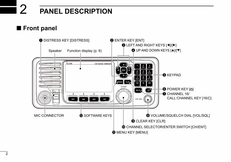
PANEL DESCRIPTION2 Front panel
q DISTRESS KEY [DISTRESS]
!1 MENU KEY [MENU]
Speaker Function display (p. 6)
w ENTER KEY [ENT]e LEFT AND RIGHT KEYS [Ω]/[≈]
r UP AND DOWN KEYS [∫]/[√]
t KEYPAD
y POWER KEY [ ]u CHANNEL 16/
CALL CHANNEL KEY [16/C]
i VOLUME/SQUELCH DIAL [VOL/SQL]o CLEAR KEY [CLR]
!0 CHANNEL SELECTOR/ENTER SWITCH [CH/ENT]
!2 SOFTWARE KEYSMIC CONNECTOR

New2001
3
2PANEL DESCRIPTION
New2001
12345678910111213141516
q DISTRESS KEY [DISTRESS] (p. 29) Hold down for 3 seconds to transmit a Distress call.
w ENTER KEY [ENT] Push to set the entered data, selected item, and so on.
e LEFT AND RIGHT KEYS [Ω]/[≈] Push to scroll the software key functions. (p. 5) In the character or number entry mode, push to select the desired character or number in the keypad. (p. 18)
r UP AND DOWN/CHANNEL SELECT KEYS [∫]/[√] Push to select the operating channel (p. 13), Menu items (p. 12), Menu settings (p. 12), and so on.
While scanning, push to check the Favorite channels, change the scanning direction or manually resume a scan. (p. 21)
t KEYPAD Push to enter numbers, letters or symbols. For channel number entry, see page 13. For channel name entry, see page 18.
y POWER KEY [ ] Hold down for 1 second to turn the transceiver ON or
OFF.
u CHANNEL 16/CALL CHANNEL KEY [16/C] Push to select Channel 16. (p. 13) Hold down for 1 second to select the Call channel. (p. 13)
• “CALL” is displayed when the Call channel is selected.
i VOLUME/SQUELCH DIAL [VOL/SQL] (p. 15) Rotate to adjust the volume level. Push once or twice to display the Volume or Squelch Setting screen, and then rotate to adjust the volume or squelch level.
o CLEAR KEY [CLR] Push to cancel the entered data, or to return to the
previous screen.
!0 CHANNEL SELECTOR/ENTER SWITCH [CH/ENT] Rotate to select the operating channel (p. 13), Menu items (p. 12), Menu settings (p. 12), and so on.
Push to set the entered data, selected item, and so on. (p. 12)
!1 MENU KEY [MENU] Push to enter or exit the Menu screen. (p. 12)

4
2 PANEL DESCRIPTION
New2001 New2001
Front panel (Continued)!2 SOFTWARE KEYS (p. 5) You can use various key functions that are assigned to
the software keys, as described below.
Compose Distress* (p. 30)
Push to display the COMPOSE DISTRESS screen.
Compose Non-Distress* (p. 42)
Push to display the COMPOSE NON-DISTRESS screen.
Compose DROBOSE* (p. 36)
Push to display the COMPOSE DROBOSE screen.
Task Mode (p. 27)
When the transceiver has any task, push to enter the Task mode.
Scan (p. 21)
Push to start or stop a Normal or Priority scan.
Dualwatch/Tri-watch [DW] (p. 22)
Push to start or stop the Dualwatch or Tri-watch.
High/Low [HI/LO] (p. 15)
Push to set the output power level to high or low. • Some channels are set to only low power.
Channel [CHAN] (p. 13)
When Channel 16 or the Call channel is selected, push to select the last selected channel.
Favorite channel [Favorite] (p. 21)
Push to set or clear the displayed channel as a Favorite channel.
Channel Name (p. 18)
Push to display the CHANNEL NAME screen.
Backlight (p. 17)
Push to open the Backlight Settings window.
DSC Log (p. 69)
Push to display the RCVD CALL LOG screen.
* These key functions are not displayed in the Radio Telephone (RT) mode. (p. 14)

New2001
5
2PANEL DESCRIPTION
12345678910111213141516
Speaker Microphone Software key functionThe transceiver has the software keys for various functions.The key function is displayed above the software key, as shown below.
D Selecting the software key function When “Ω” or “≈” is displayed beside the key icon, pushing [Ω] or [≈] scrolls the software key functions.When you push [Ω] or [≈] once, 4 functions scroll together.
Push this key to display the COMPOSE DISTRESS screen.
q PTT SWITCH [PTT] (pp. 15, 29) Hold down to transmit, release to receive.w UP/DOWN KEYS [Y]/[Z] (p. 21) Push to select the Favorite channels, change scanning
direction or manually resume a scan. • When the “FAV on MIC” item is set to “OFF,” you can select all
channels. (p. 78)
e TRANSMIT POWER KEY [H/L] Push to set the power level to high or low. (p. 15)
• Some channels are set to only low power. While holding down this key, turn ON the transceiver to turn the Microphone Lock function ON or OFF. (p. 17)
r CHANNEL 16/CALL CHANNEL KEY [16/C] (p. 13) Push to select Channel 16. Hold down for 1 second to select the Call channel.
• The “CALL” icon is displayed.
q PTT SWITCH [PTT]
w UP/DOWN KEYS [Y]/[Z]
e TRANSMIT POWER KEY [H/L]
Microphone
r CHANNEL 16/ CALL CHANNEL KEY [16/C]
Push
Push
Push
Push

6
2 PANEL DESCRIPTION
New2001
Display area Descriptionq Status area Displays the current status.w Task area Displays up to 7 task icons.e Information area Displays various icons and the
MMSI code.r Channel area Displays the selected operating
channel information. (p. 7)t Software key area Displays the key function for each
software key. (p. 5)y Position and Time
areaDisplays the current position and time. (p. 8)
e Information area
t Software key area
r Channel areaw Task area
y Position and Time area
Function display (Main screen) D Status area
The current status is displayed in the Status area.
Indicator DescriptionSCAN 16 Displayed during a Priority scan. (p. 21)SCAN Displayed during a Normal scan. (p. 21)DUAL 16 Displayed during Dualwatch. (p. 22)TRI 16 Displayed during Tri-watch. (p. 22)
D Task areaUp to 7 task icons are displayed in the Task area when the transceiver has a task.
Indicator DescriptionDisplayed while in the Radio Telephone (RT) mode. (p. 14)• “ ” is displayed when the RT mode task is
activated.• Disappears if no operation occurs during the
preset period of time. (p. 80)Displayed after receiving a DSC call. (p. 27)• “ ” is displayed when the RX call task is
activated.
Displayed after making a DSC call. (p. 27)• “ ” is displayed when the TX call task is
activated.
q Status area

7
2PANEL DESCRIPTION
New2001
12345678910111213141516
D Information areaThe 9 digit MMSI (Maritime Mobile Service Identity: DSC self ID) code and the following indicators are displayed in the Information area.
Indicator DescriptionDisplayed when receiving a signal or when the squelch is open.Displayed while transmitting.
25W Displayed when high power is selected.1W Displayed when low power is selected.
Displayed when the transceiver receives a valid GPS data from the GPS receiver.Blinks while invalid GPS data is being received.Blinks when there is an unread DSC message.
Displayed when the “Internal Speaker” item is OFF. (p. 81)Displayed when the battery voltage is low.
D Channel areaThe selected operating channel number, channel name, and the following indicators are displayed in the Channel area.
Indicator DescriptionDisplayed when a Favorite (Tag) channel is selected.
CALL Displayed when the Call channel is selected.DUP Displayed when a Duplex channel is selected.
8
2 PANEL DESCRIPTION
New2001 New2001
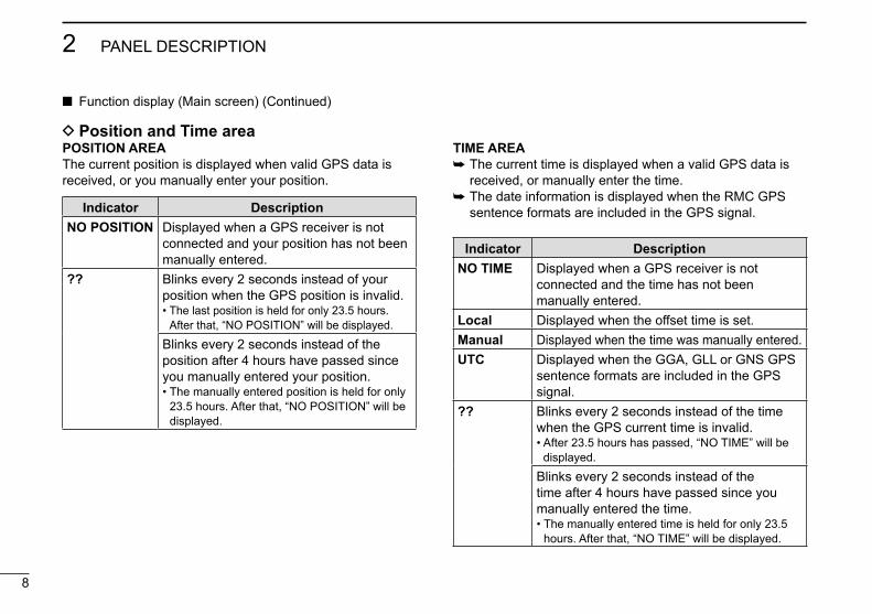
D Position and Time areaPOSITION AREA The current position is displayed when valid GPS data is received, or you manually enter your position.
Indicator DescriptionNO POSITION Displayed when a GPS receiver is not
connected and your position has not been manually entered.
?? Blinks every 2 seconds instead of your position when the GPS position is invalid.• The last position is held for only 23.5 hours.
After that, “NO POSITION” will be displayed.
Blinks every 2 seconds instead of the position after 4 hours have passed since you manually entered your position.• The manually entered position is held for only
23.5 hours. After that, “NO POSITION” will be displayed.
TIME AREA The current time is displayed when a valid GPS data is received, or manually enter the time.
The date information is displayed when the RMC GPS sentence formats are included in the GPS signal.
Indicator DescriptionNO TIME Displayed when a GPS receiver is not
connected and the time has not been manually entered.
Local Displayed when the offset time is set.Manual Displayed when the time was manually entered.UTC Displayed when the GGA, GLL or GNS GPS
sentence formats are included in the GPS signal.
?? Blinks every 2 seconds instead of the time when the GPS current time is invalid.• After 23.5 hours has passed, “NO TIME” will be
displayed.
Blinks every 2 seconds instead of the time after 4 hours have passed since you manually entered the time.• The manually entered time is held for only 23.5
hours. After that, “NO TIME” will be displayed.
Function display (Main screen) (Continued)

9
3PREPARATION
New2001
12345678910111213141516
First, you must enter the 9 digit MMSI (Maritime Mobile Service Identity: DSC self ID) code at power ON.
You can perform this initial code entry ONLY ONCE. After entry, only your dealer or distributor can change it. If you have already entered your MMSI code, these procedures are not necessary.
q Hold down [ ] for 1 second to turn ON the transceiver.
• Three short beeps sound. • “Push [ENT] to Register Your MMSI” is
displayed. w Push [ENT] to enter the MMSI code entry mode.
Push
• Push [CLR] to cancel the entry. In that case, the transceiver displays “Push [ENT] to Register Your MMSI” again.
Entering the MMSI code e Enter your 9 digit MMSI code.
r After entering the 9th digit, set the ID.Push
t ReenteryourMMSIcodetoconfirm.
y After entering the 9th digit, register the ID.
Push
• When you successfully enter your MMSI code, the following screen is displayed.
• After that, the Main screen is displayed. The registered MMSI code is displayed at the top of the screen.
+Rotate
Push
+Rotate
Push
10
New2001New2001
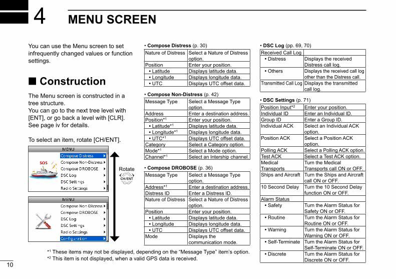
MENU SCREEN4• Compose Distress (p. 30)Nature of Distress Select a Nature of Distress
option.Position Enter your position. • Latitude Displays latitude data. • Longitude Displays longitude data. • UTC Displays UTC offset data.
• Compose Non-Distress (p. 42)Message Type Select a Message Type
option.Address Enter a destination address.Position*1 Enter your position. • Latitude*1 Displays latitude data. • Longitude*1 Displays longitude data. • UTC*1 Displays UTC offset data.Category Select a Category option.Mode*1 Select a Mode option.Channel*1 Select an Intership channel.
• Compose DROBOSE (p. 36)Message Type Select a Message Type
option.Address*1 Enter a destination address.Distress ID Enter a Distress ID.Nature of Distress Select a Nature of Distress
option.Position Enter your position. • Latitude Displays latitude data. • Longitude Displays longitude data. • UTC Displays UTC offset data.Mode Displays the
communication mode.
• DSC Log (pp. 69, 70)Received Call Log • Distress Displays the received
Distress call log. • Others Displays the received call log
other than the Distress call.Transmitted Call Log Displays the transmitted
call log.
• DSC Settings (p. 71)Position Input*2 Enter your position.Individual ID Enter an Individual ID.Group ID Enter a Group ID.Individual ACK Select an Individual ACK
option.Position ACK Select a Position ACK
option.Polling ACK Select a Polling ACK option.Test ACK Select a Test ACK option.Medical Transports
Turn the Medical Transports call ON or OFF.
Ships and Aircraft Turn the Ships and Aircraft call ON or OFF.
10 Second Delay Turn the 10 Second Delay function ON or OFF.
Alarm Status • Safety Turn the Alarm Status for
Safety ON or OFF. • Routine Turn the Alarm Status for
Routine ON or OFF. • Warning Turn the Alarm Status for
Warning ON or OFF. • Self-Terminate Turn the Alarm Status for
Self-Terminate ON or OFF. • Discrete Turn the Alarm Status for
Discrete ON or OFF.
You can use the Menu screen to set infrequently changed values or function settings.
ConstructionThe Menu screen is constructed in a tree structure.You can go to the next tree level with [ENT], or go back a level with [CLR].See page iv for details.
To select an item, rotate [CH/ENT].
Rotate
*1 These items may not be displayed, depending on the “Message Type” itemʼs option.*2 This item is not displayed, when a valid GPS data is received.

11
4MENU SCREEN
New2001
12345678910111213141516
New2001
• DSC Settings (Continued)CH70 SQL Level Select the Channel 70
squelch level.Auto Print Turn the Auto Print function
ON or OFF.DSC Loop Test Starts the DSC Loop Test.
• Radio Settings (p. 77)Scan Type Select a Scan Type from
Normal Scan or Priority Scan
Scan Timer Turn the Scan Timer function ON or OFF.
Dual/Tri-Watch Select the Dualwatch or Tri-watch function.
Call Channel Set the Call channel.FAV on MIC Turn the FAV on MIC
function ON or OFF.FAV Settings Set the Favorite channel
settings.
• Configuration (p. 78)Key Beep Turn the Key Beep function
ON or OFF.UTC Offset Set the UTC Offset.Inactivity Timer Set the inactivity timer. • Not DSC
RelatedSet the inactivity timer for not DSC related calls.
• DSC Related Set the inactivity timer for DSC related calls.
• Distress Related
Set the inactivity timer for Distress related calls.
• RT Related Set the inactivity timer for the Radio Telephone mode.
NMEA Data Output
Set the NMEA 0183 Output functions.
• DSC Data Output
Select a DSC Data Output option.
• POS Data Output
Select a Position Data Output option.
Internal Speaker Turn the Internal Speaker function ON or OFF.
MIC Type Select a microphone type.Software Version Display the software
version.

12
4 MENU SCREEN
New2001
Selecting a Menu itemFollow the procedures as described below to select a Menu item.
Example: Set the Tri-watch function. q Push [MENU] to display the MENU screen. w Rotate [CH/ENT] to select “Radio Settings,” then push [ENT].
+Push
Rotate
e Rotate [CH/ENT] to select “Dual/Tri-Watch,” then push [ENT].
+Push
Rotate
r Rotate [CH/ENT] to select “Tri-Watch,” then push [ENT].
+Push
Rotate
• Sets the Tri-watch function, and then goes back to the RADIO SETTINGS screen, after pushing [ENT].
t Push [MENU] to return to the Main screen.

13
5BASIC OPERATION
New2001
12345678910111213141516
New2001
D Selecting a regular channel
Selecting a channel in sequence:
Rotate [CH/ENT]. Push [∫] or [√].
Entering the desired channel number:
Push the keypad to directly enter the desired channel number.
Example: Selecting Channel 22Push [2 abc] → [2 abc].
D Selecting Channel 16Channel 16 is the distress and safety channel. It is used for establishing initial contact with a station, and for emergency communications.While standing by, you must monitor Channel 16.
Push [16/C].
To recall the channel that was displayed before selecting Channel 16:
Push [CHAN] .
D Selecting Call channelYou have a leisure use Call channel for quick recall.To set your most used channel, see page 14.The default Call channel is Channel 16.
Hold down [16/C] for 1 second.
To recall the channel that was displayed before selecting Call channel:
Push [CHAN] .
Selecting a channel

14
5 BASIC OPERATION
New2001
You can set the Call channel with your most often-used channel for quick recall.
q Push [MENU] to display the MENU screen. w Rotate [CH/ENT] to select “Radio Settings,” then push [ENT].
+Push
Rotate
e Rotate [CH/ENT] to select “Call Channel,” then push [ENT].
+Push
Rotate
r Rotate [CH/ENT] to select the desired channel to be set as the Call channel, then push [ENT].
+Push
Rotate
• Goes back to the previous screen, after pushing [ENT].
t Push [MENU] to return to the Main screen.
Setting the Call channel
TIP: To confirm that your setting is correctly set, hold down [16/C] for 1 second. (p. 13)
TIP: After receiving a signal or you operate the transceiver, the transceiver enters the Radio Telephone (RT) mode.In the RT mode, you can make a voice communication except for the DSC operation.• “ ” is displayed while in the RT mode.• “ ” is displayed when the RT mode
task is activated.• “ ” or “ ” disappears if no operation
occurs during the preset period of time. (p. 80)
• The following software key functions are not displayed in the RT mode. [Compose Distress] [Compose Non-Distress] [Compose DROBOSE]
Selecting a channel (Continued)
15
5BASIC OPERATION
New2001
12345678910111213141516
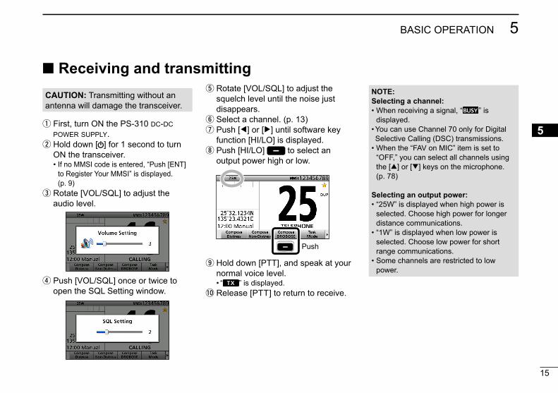
Receiving and transmittingCAUTION: Transmitting without an antenna will damage the transceiver.
q First, turn ON the PS-310 dc-dc power supply. w Hold down [ ] for 1 second to turn ON the transceiver.
• If no MMSI code is entered, “Push [ENT] to Register Your MMSI” is displayed. (p. 9)
e Rotate [VOL/SQL] to adjust the audio level.
r Push [VOL/SQL] once or twice to open the SQL Setting window.
t Rotate [VOL/SQL] to adjust the squelch level until the noise just disappears. y Select a channel. (p. 13) u Push [Ω] or [≈] until software key function [HI/LO] is displayed. i Push [HI/LO] to select an output power high or low.
Push
o Hold down [PTT], and speak at your normal voice level.
• “ ” is displayed.!0 Release [PTT] to return to receive.
NOTE:Selecting a channel:• When receiving a signal, “ ” is
displayed.• You can use Channel 70 only for Digital Selective Calling (DSC) transmissions.
• When the “FAV on MIC” item is set to “OFF,” you can select all channels using the [∫] or [√] keys on the microphone. (p. 78)
Selecting an output power:• “25W” is displayed when high power is
selected. Choose high power for longer distance communications.
• “1W” is displayed when low power is selected. Choose low power for short range communications.
• Some channels are restricted to low power.
16
5 BASIC OPERATION
New2001
Microphone
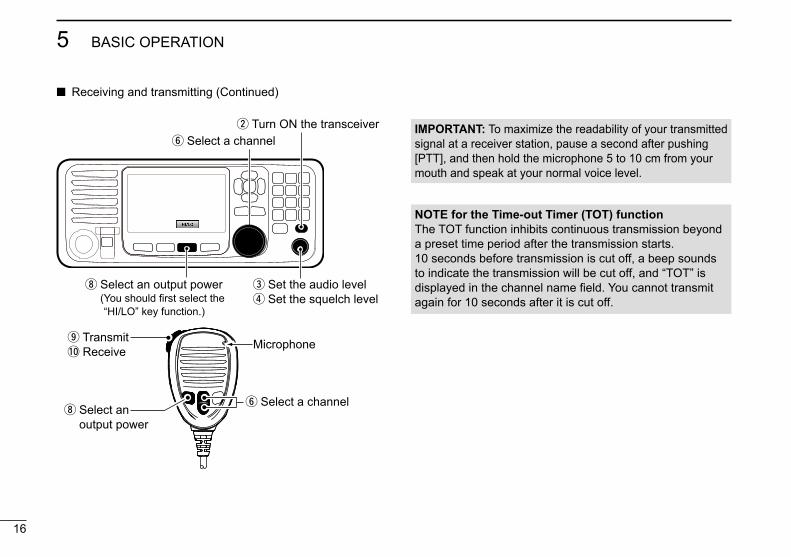
y Select a channel
o Transmit!0 Receive
i Select an output power
w Turn ON the transceiver
e Set the audio level r Set the squelch level
y Select a channel
i Select an output power ( You should first select the “HI/LO” key function.)
IMPORTANT: To maximize the readability of your transmitted signal at a receiver station, pause a second after pushing [PTT], and then hold the microphone 5 to 10 cm from your mouth and speak at your normal voice level.
NOTE for the Time-out Timer (TOT) functionThe TOT function inhibits continuous transmission beyond a preset time period after the transmission starts.10 seconds before transmission is cut off, a beep sounds to indicate the transmission will be cut off, and “TOT” is displayed in the channel name field. You cannot transmit again for 10 seconds after it is cut off.
Receiving and transmitting (Continued)
17
5BASIC OPERATION
New2001
12345678910111213141516
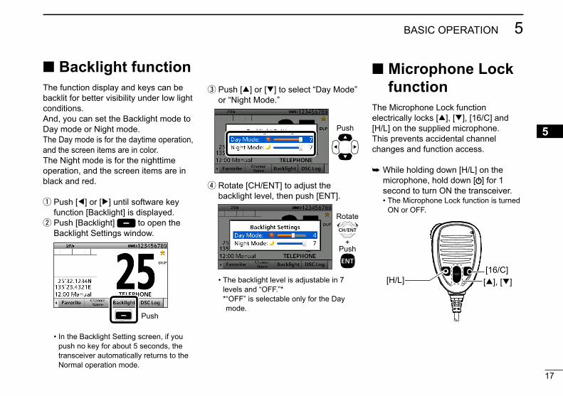
Backlight functionThe function display and keys can be backlit for better visibility under low light conditions.And, you can set the Backlight mode to Day mode or Night mode.The Day mode is for the daytime operation, and the screen items are in color.The Night mode is for the nighttime operation, and the screen items are in black and red.
q Push [Ω] or [≈] until software key function [Backlight] is displayed. w Push [Backlight] to open the Backlight Settings window.
Push
• In the Backlight Setting screen, if you push no key for about 5 seconds, the transceiver automatically returns to the Normal operation mode.
e Push [∫] or [√] to select “Day Mode” or “Night Mode.”
Push
r Rotate [CH/ENT] to adjust the backlight level, then push [ENT].
+Push
Rotate
• The backlight level is adjustable in 7 levels and “OFF.”* * “OFF” is selectable only for the Day mode.
Microphone Lock function
The Microphone Lock function electrically locks [∫], [√], [16/C] and [H/L] on the supplied microphone. This prevents accidental channel changes and function access.
While holding down [H/L] on the microphone, hold down [ ] for 1 second to turn ON the transceiver.
• The Microphone Lock function is turned ON or OFF.
[∫], [√][16/C]
[H/L]

18
5 BASIC OPERATION
New2001
You can rename each channel with a unique alphanumeric ID of up to 10 characters.
q First, cancel the Dualwatch, Tri-watch or Scan function, if activated. w Rotate [CH/ENT] to select a channel. e Push [Channel Name] .
Push
Entering a Channel name Using [Y], [Z], [Ω], or [≈]:
Push [Y], [Z], [Ω], or [≈] to select the desired character. Then, push [ENT] to enter the character.
(Example: Entering “S”)
+Push
Push
• To move the cursor, push [Y], [Z], [Ω], or [≈] to select either arrow, “←” or “→,” then push [ENT].
• You can enter capital letters, 0 to 9, some symbols (! " # $ % & ' ( ) * + , – . / [ \ ] ^ _ : ; < = > ?) and a space.
r Enter the desired character.
Using the keypad:
Push a keypad to enter a character. (Example: Entering “S”)
5 times
Push
• To move the cursor, rotate [CH/ENT]. • You can enter the following characters
by pushing the keypad one or more times.
KEY ENTRY KEY ENTRY
[1] 1 [6] 6 M N O
[2] 2 A B C [7] 7 P Q R S
[3] 3 D E F [8] 8 T U V
[4] 4 G H I [9] 9 W X Y Z
[5] 5 J K L [0] 0 . (period)
See ʽCommon operationʼ as described on page 19 for details of the following operations.• Entering a symbol/space• Deleting a character• Canceling an entry• Correcting an entry

19
5BASIC OPERATION
New2001
12345678910111213141516
Common operation
• To enter a symbol: Push [“!$?”] , then push [Y], [Z], [Ω], or [≈] to select the desired character. And then, push [ENT].
• To enter a space: Push [Y], [Z], [Ω], or [≈] to select a “Space,” and then push [ENT].
• To delete a character: Push [Y], [Z], [Ω], or [≈] to select “Delete,” and then push [ENT].
• To cancel an entry: Push [CLR].
• To correct an entry: Move the cursor to the character, and then, enter the correct character.
t Repeat step r to enter all characters. y Push [Y], [Z], [Ω], or [≈] to select “Done,” then push [ENT].
• Return to the previous screen. • During the keypad operation, “Done” is
automatically selected.

New2001
20
New2001
SCAN OPERATION6 Scan types
You can find ongoing calls by scanning the Favorite channels without rotating [CH/ENT].
The GM600 has two scan types.• Priority scan (default)• Normal scan
Before you start a scan:• Set the desired channels you want to scan as Favorite
channels. (Scans only Favorite channels.) (p. 21)• Set the desired scan type to “Normal" or “Priority.”
(p. 77)
NORMAL SCANA Normal scan sequentially scans all Favorite channels. However, the scan does not check Channel 16 unless it is set as a Favorite channel.
CH 01 CH 02
CH 03
CH 04CH 05
CH 06
PRIORITY SCANA Priority scan sequentially scans all Favorite channels while also monitoring Channel 16.
CH 16
CH 01 CH 02
CH 03
CH 04CH 05
CH 06
When a signal is received:• On Channel 16The scan pauses until the signal on Channel 16 disappears.
• On a channel other than Channel 16:The scan switches to Dualwatch, until the signal disappears.

New2001
21
6SCAN OPERATION
New2001
12345678910111213141516
Favorite channelsYou can quickly recall often-used channels by setting them as Favorite channels.All channels are set as Favorite channels by default.
D Setting q Rotate [CH/ENT] to select a channel. w Push [Favorite] to set the channel as a Favorite channel.
• “ ” is displayed.
Starting a scan q Push [Scan] to start a scan.
• During a Priority scan, “SCAN 16” is displayed. During a Normal scan, “SCAN” is displayed.
w Push [Scan] again to cancel the scan. • “SCAN 16” or “SCAN” disappears.
D Selecting Push [∫] or [√] on the microphone.
• Non-Favorite channels are skipped and not displayed. • When the “FAV on MIC” item is set to “OFF,” you can select all
channels. (p. 78)
D Clearing q Select a Favorite channel to clear. w Push [Favorite] to clear the channel as the Favorite channel.
• “ ” disappears.
Example: Starting a priority scan.
Scanning starts
When a signal is received
NOTE:• When a signal is received, the scan pauses until the signal
disappears, or resumes after pausing for 5 seconds, depending on the “Scan Timer” setting. (p. 77)
• You can check the scanning channel, change the scan direction, or manually resume the scan by pushing [∫] or [√] on either the transceiver or the microphone.
• A beep tone sounds and “16” blinks when a signal is received on Channel 16 during a Priority scan.
• In order to properly receive signals, you must adjust the squelch to the proper level. (p. 15)
Push
TIP: You can clear all Favorite channels in the Menu screen. (p. 78)
TIP: You can select all channels by rotating [CH/ENT] or pushing [∫] or [√] on the transceiver. (p. 13)

22
New2001
DUALWATCH/TRI-WATCH7 Description
Dualwatch and Tri-watch are convenient to monitor Channel 16 while you are listening or talking on another channel.
When a signal is received on the Channel 16.
Dualwatch resumes after the signal disappears.
Dualwatch Tri-watch
CH 88CH 16
CH 88
CH 16CH 9
Monitors Channel 16 while listening or talking on another channel (example: CH 88).
Monitors Channel 16 and the Call channel while listening or talking on another channel (example: CH 88).
Callchannel
When a signal is received:• On Channel 16Dualwatch/Tri-watch pauses on Channel 16 until the signal disappears.
• On the Call channelTri-watch switches to Dualwatch until the signal on the Call channel disappears.
Operation q Select Dualwatch or Tri-watch in the Menu screen. (p. 77) w Select a channel. (p. 13) e Push [DW] to start Dualwatch or Tri-watch.
• During Dualwatch, “DUAL 16” is displayed. During Tri-watch, “TRI 16” is displayed.
• A beep tone sounds and “16” starts to blink when a signal is received on Channel 16.
r Push [DW] again to cancel Dualwatch or Tri-watch.
Example: Operating Dualwatch on Channel 07.
Push
Dualwatch starts.

23
8DSC OPERATION
New2001
12345678910111213141516
New2001
DSC address ID
D Entering Individual ID q Push [MENU]. w Select “Individual ID,” then push [ENT].
( DSC Settings > Individual ID) e Push [Add] .
Push
r Enter a 9 digit Individual ID.
+Rotate
Push
TIP: You must set the first digit for the Individual ID to between ʻ1ʼ and ʻ9.ʼ• The first digit must be set to ‘0’ for a
Group ID.• The first two digits must be set to ‘0’ for
any Coast station ID.
t After entering all 9 digits, push [ENT]. y Enter the desired ID name.
+Rotate
Push
• See page 18 for text entry details.
You can enter a total of 100 DSC address IDs (Individual ID: 75, Group ID: 25), and assign a name of up to 10 characters.
u After entering, push [ENT].Push
• The entered Individual ID and name are added to the ID list.
i Push [MENU] to return to the Main screen.
24
8 DSC OPERATION
New2001
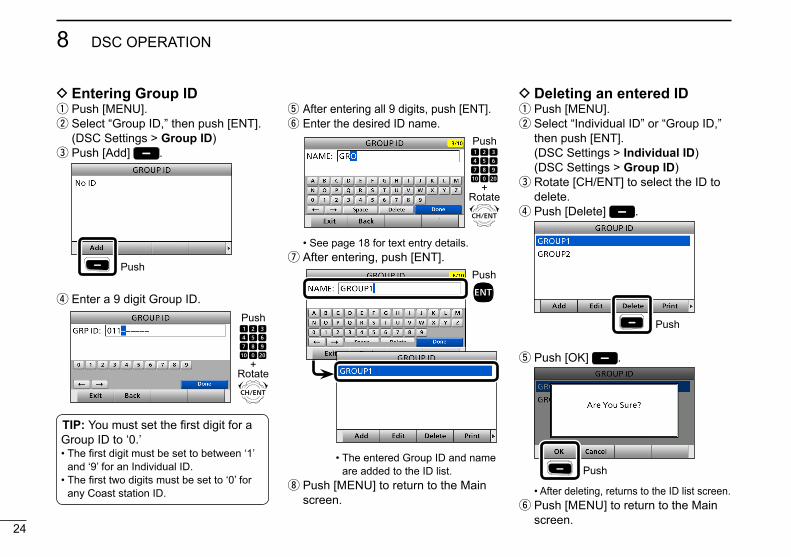
D Entering Group ID q Push [MENU]. w Select “Group ID,” then push [ENT].
(DSC Settings > Group ID) e Push [Add] .
Push
r Enter a 9 digit Group ID.
+Rotate
Push
TIP: You must set the first digit for a Group ID to ‘0.’• The first digit must be set to between ‘1’
and ‘9’ for an Individual ID.• The first two digits must be set to ‘0’ for
any Coast station ID.
t After entering all 9 digits, push [ENT]. y Enter the desired ID name.
+Rotate
Push
• See page 18 for text entry details. u After entering, push [ENT].
Push
• The entered Group ID and name are added to the ID list.
i Push [MENU] to return to the Main screen.
D Deleting an entered ID q Push [MENU]. w Select “Individual ID” or “Group ID,” then push [ENT].
( DSC Settings > Individual ID) (DSC Settings > Group ID)
e Rotate [CH/ENT] to select the ID to delete. r Push [Delete] .
Push
t Push [OK] .
Push
• After deleting, returns to the ID list screen. y Push [MENU] to return to the Main screen.
25
8DSC OPERATION
New2001
12345678910111213141516
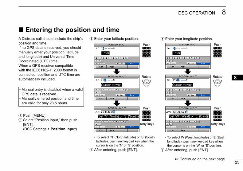
Entering the position and timeA Distress call should include the ship’s position and time. If no GPS data is received, you should manually enter your position (latitude and longitude) and Universal Time Coordinated (UTC) time.When a GPS receiver compatible with the IEC61162-1: 2000 format is connected, position and UTC time are automatically included.
• Manual entry is disabled when a valid GPS data is received.
• Manually entered position and time are valid for only 23.5 hours.
q Push [MENU]. w Select “Position Input,” then push [ENT].
(DSC Settings > Position Input)
e Enter your latitude position.
Push
Enter
Cursor moves
Set ‘N’ (North) or ‘S’ (South)
Rotate
Push
(any key)
• To select ʻNʼ (North latitude) or ʻSʼ (South latitude), push any keypad key when the cursor is on the ‘N’ or ‘S’ position.
r After entering, push [ENT].
t Enter your longitude position.
Push
Enter
Cursor moves
Set ‘W’ (West) or ‘E’ (East)
Rotate
Push
(any key)
• To select W (West longitude) or E (East longitude), push any keypad key when the cursor is on the ‘W’ or ‘E’ position.
y After entering, push [ENT].
Continued on the next page.
26
8 DSC OPERATION
New2001
Entering the position and time
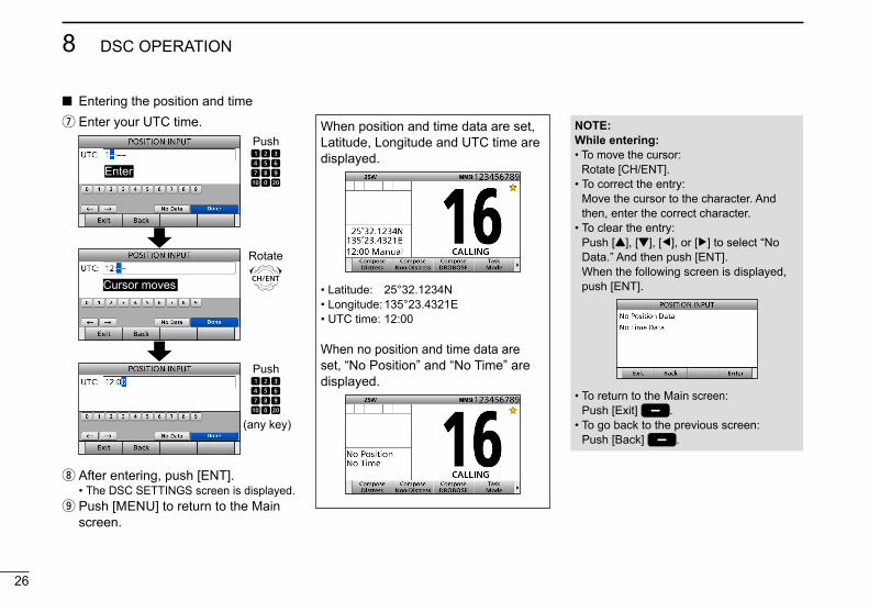
NOTE:While entering:• To move the cursor:
Rotate [CH/ENT].• To correct the entry:
Move the cursor to the character. And then, enter the correct character.
• To clear the entry: Push [Y], [Z], [Ω], or [≈] to select “No Data.” And then push [ENT]. When the following screen is displayed, push [ENT].
• To return to the Main screen: Push [Exit] .
• To go back to the previous screen: Push [Back] .
u Enter your UTC time.
Push
Enter
Cursor moves
Rotate
Push
(any key)
i After entering, push [ENT]. • The DSC SETTINGS screen is displayed.
o Push [MENU] to return to the Main screen.
When position and time data are set, Latitude, Longitude and UTC time are displayed.
• Latitude: 25°32.1234N• Longitude: 135°23.4321E• UTC time: 12:00
When no position and time data are set, “No Position” and “No Time” are displayed.

27
8DSC OPERATION
New2001
12345678910111213141516
DSC Task modeAfter sending or receiving a DSC call, the transceiver enters the DSC Task mode.
(Example: After receiving an All Ships call)
In the Task mode, you can resend the call, or send an acknowledgement to the caller station, and so on.• The transceiver can hold up to 7 tasks.• In the standby mode, a task icon is
displayed in the Task area, when the transceiver has a DSC task.
• When any task icon is displayed in the standby mode, you can enter the Task mode by pushing [Task Mode] .
D About “Active” and “Hold”The Task mode has two statuses, Active and Hold. When you resend the call, or send an acknowledgement to a caller station, push [Active] to enter the DSC Task mode.
• Hold window
• To view the contents, push [∫] or [√].
• Active window
• “” is displayed on the active Task tab.• To view the contents, rotate [CH/ENT].
NOTE: The Task mode has a TOT (Time-out Timer) function. When you push no key for a preset period, the transceiver automatically exits the Task mode.The count down alarm sounds 10 seconds before the TOT activates.No count down alarm sounds before Radio Telephone TOT activates.The default settings of the TOT function. • Distress call: OFF • Non-Distress call: 15 minutes
28
8 DSC OPERATION
New2001
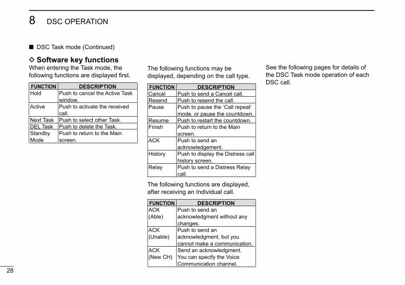
D Software key functionsWhen entering the Task mode, the following functions are displayed first.
FUNCTION DESCRIPTIONHold Push to cancel the Active Task
window.Active Push to activate the received
call.Next Task Push to select other Task.DEL Task Push to delete the Task.Standby Mode
Push to return to the Main screen.
DSC Task mode (Continued)
See the following pages for details of the DSC Task mode operation of each DSC call.
The following functions may be displayed, depending on the call type.
FUNCTION DESCRIPTIONCancel Push to send a Cancel call.Resend Push to resend the call.Pause Push to pause the ‘Call repeat’
mode, or pause the countdown.Resume Push to restart the countdown.Finish Push to return to the Main
screen.ACK Push to send an
acknowledgement.History Push to display the Distress call
history screen.Relay Push to send a Distress Relay
call.
The following functions are displayed, after receiving an Individual call.
FUNCTION DESCRIPTIONACK (Able)
Push to send an acknowledgment without any changes.
ACK (Unable)
Push to send an acknowledgment, but you cannot make a communication.
ACK (New CH)
Send an acknowledgment. You can specify the Voice Communication channel.
29
8DSC OPERATION
New2001
12345678910111213141516
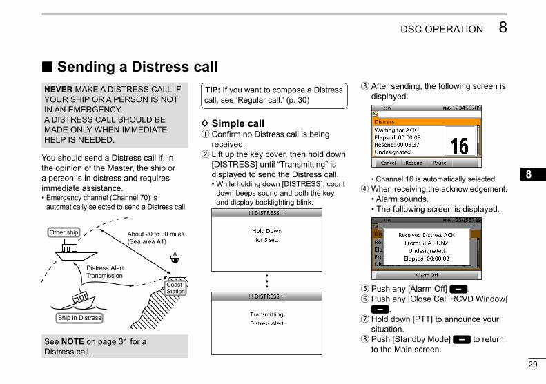
Sending a Distress call
You should send a Distress call if, in the opinion of the Master, the ship or a person is in distress and requires immediate assistance.• Emergency channel (Channel 70) is
automatically selected to send a Distress call.
D Simple call q Confirm no Distress call is being received. w Lift up the key cover, then hold down [DISTRESS] until “Transmitting” is displayed to send the Distress call.
• While holding down [DISTRESS], count down beeps sound and both the key and display backlighting blink.
•••
e After sending, the following screen is displayed.
• Channel 16 is automatically selected. r When receiving the acknowledgement:
• Alarm sounds. • The following screen is displayed.
t Push any [Alarm Off] . y Push any [Close Call RCVD Window]
. u Hold down [PTT] to announce your situation. i Push [Standby Mode] to return to the Main screen.
About 20 to 30 miles(Sea area A1)
Distress AlertTransmission
Ship in Distress
Other ship
CoastStation
See NOTE on page 31 for a Distress call.
NEVER MAKE A DISTRESS CALL IF YOUR SHIP OR A PERSON IS NOT IN AN EMERGENCY.A DISTRESS CALL SHOULD BE MADE ONLY WHEN IMMEDIATE HELP IS NEEDED.
TIP: If you want to compose a Distress call, see ʻRegular call.ʼ (p. 30)

30
8 DSC OPERATION
New2001
Sending a Distress call (Continued) D Regular call
You can compose the Distress call.
Step 1. Display the COMPOSE DISTRESS screen
q Push [Compose Distress] .
Push
• To display the screen from the Menu screen: ([MENU] > Compose Distress)
Step 2. Setting “Nature of Distress”
q Push [ENT].
Push
w Select the desired option, then push [ENT]. (Example: Fire,Explosion)
+Push
Rotate
Options: Undesignated, Fire,Explosion, Flooding, Collision, Grounding, Capsizing, Sinking, Adrift, Abandoning Ship, Piracy, and Man Overboard.
• The transceiver stores this setting for 30 seconds.
You can skip Step 3 below if your position and time data are valid.In that case, go to Step 4.
Step 3. Entering “Position”
q Select “Position,” then push [ENT]. • The position entry screen is displayed.
w Enter your position and time data. • See page 25 for entering details.
e After entering, push [ENT].
Step 4. Sending
q Lift up the key cover, then hold down [DISTRESS] until “Transmitting” is displayed to send the Distress call.
• While holding down [DISTRESS], count down beeps sound and both the key and display backlighting blink.
•••

31
8DSC OPERATION
New2001
12345678910111213141516
w After sending, the following screen is displayed.
• Channel 16 is automatically selected. • See page 28 for details of the Task
mode's software key functions.
NOTE:Transmitting:• A distress alert default contains: - Nature of distress: Undesignated distress (Simple call) Selected in Step 2 (Regular call) - Position information: The latest GPS or manual input
position is held for 23.5 hours, or until the power is turned OFF.
Waiting for an acknowledgement:• The transceiver automatically sends a
Distress call every 3.5 to 4.5 minutes, until receiving an acknowledgement (‘Call repeat’ mode), or sending a DSC Cancel call. (p. 33)
• To manually send a Distress Repeat call: Push [Resend] .
• To view the call contents: Rotate [CH/ENT].
• To pause the ‘Call repeat’ mode: Push [Pause] . To resume it: Push [Resume Countdown] .
Step 5. Replying
q When the acknowledgement is received:
• Alarm sounds. • The following screen is displayed.
w Push any [Alarm Off] . e Push any [Close Call RCVD Window]
. r Hold down [PTT] to announce your situation. t Push [Standby Mode] to return to the Main screen.
32
8 DSC OPERATION
New2001
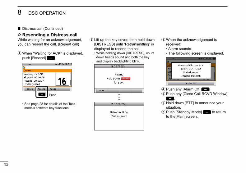
D Resending a Distress callWhile waiting for an acknowledgement, you can resend the call. (Repeat call)
q When “Waiting for ACK” is displayed, push [Resend] .
Push
• See page 28 for details of the Task mode's software key functions.
e When the acknowledgement is received:
• Alarm sounds. • The following screen is displayed.
r Push any [Alarm Off] . t Push any [Close Call RCVD Window]
. y Hold down [PTT] to announce your situation. u Push [Standby Mode] to return to the Main screen.
w Lift up the key cover, then hold down [DISTRESS] until “Retransmitting” is displayed to resend the call.
• While holding down [DISTRESS], count down beeps sound and both the key and display backlighting blink.
•••
Distress call (Continued)
33
8DSC OPERATION
New2001
12345678910111213141516
33
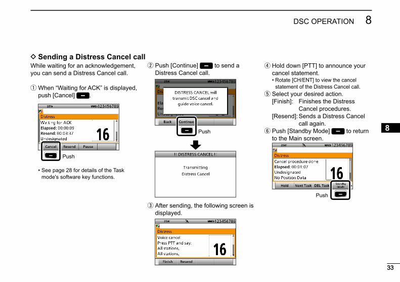
While waiting for an acknowledgement, you can send a Distress Cancel call.
q When “Waiting for ACK” is displayed, push [Cancel] .
Push
• See page 28 for details of the Task mode's software key functions.
w Push [Continue] to send a Distress Cancel call.
Push
e After sending, the following screen is displayed.
r Hold down [PTT] to announce your cancel statement.
• Rotate [CH/ENT] to view the cancel statement of the Distress Cancel call.
t Select your desired action. [Finish]: Finishes the Distress
Cancel procedures. [Resend]: Sends a Distress Cancel
call again. y Push [Standby Mode] to return to the Main screen.
Push
D Sending a Distress Cancel call
34
8 DSC OPERATION
New2001
Distress call (Continued)
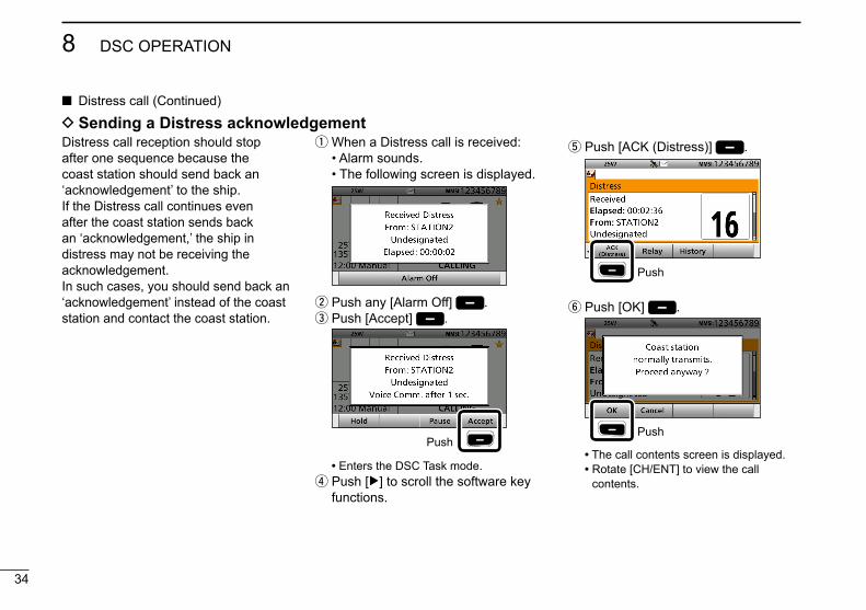
D Sending a Distress acknowledgement q When a Distress call is received:
• Alarm sounds. • The following screen is displayed.
w Push any [Alarm Off] . e Push [Accept] .
Push
• Enters the DSC Task mode. r Push [≈] to scroll the software key functions.
Distress call reception should stop after one sequence because the coast station should send back an ‘acknowledgement’ to the ship.If the Distress call continues even after the coast station sends back an ‘acknowledgement,’ the ship in distress may not be receiving the acknowledgement. In such cases, you should send back an ‘acknowledgement’ instead of the coast station and contact the coast station.
t Push [ACK (Distress)] .
Push
y Push [OK] .
Push
• The call contents screen is displayed. • Rotate [CH/ENT] to view the call
contents.

35
8DSC OPERATION
New2001
12345678910111213141516
u Push [Call] to send a Distress acknowledgement.
Push
i After sending, the following screen is displayed.
o Hold down [PTT] to communicate with the ship in distress.
!0 Push [Standby Mode] to return to the Main screen.
TIP: When you push [Pause] in step 3, the countdown will be paused. Push [Resume] to restart the countdown.

36
8 DSC OPERATION
New2001
Distress call
There are two ways to transmit the Distress Relay call—“Distress Relay On Behalf Of Someone Else (DROBOSE)” and “Distress Relay Call with Distress Call Log”.NOTE: DO NOT push [DISTRESS] to transmit a Distress Relay call. You should use it for only your own shipʼs Distress call.
To transmit the Distress Relay call with “DROBOSE”:You may transmit a Distress Relay call when a ship in distress cannot successfully send a Distress call, or when you find a ship in distress and it requires your immediate help.
Your ship
Coast Station
Distress Relay Transmission
Ship in Distress
No DistressTransmission
q Push [Compose DROBOSE] to display the COMPOSE DROBOSE screen.
Push
• To display the screen from the Menu screen: ([MENU] > Compose DROBOSE)
w Select “Message Type,” then push [ENT]. e Select the desired message type, then push [ENT].
(Example: Individual)
+Push
Rotate
When you select “All Ships” in step e, “Address” is not displayed in step r. In that case, go to step y.
r Select “Address,” then push [ENT]. t Select the desired coast station address or “Manual Input,” then push [ENT].
(Example: STATION1)
+Push
Rotate
When you select “Manual Input” in step t, push the keypad to manually enter the desired Individual ID. (p. 23)
y Select “Distress ID,” then push [ENT].
D Sending a Distress Relay call

37
8DSC OPERATION
New2001
12345678910111213141516
u Select “Manual Input,” then push [ENT].
+Push
Rotate
The Distress Call Log is displayed after receiving the Distress call.DO NOT select an ID for DROBOSE.
i Enter the 9 digit Distress ID (MMSI ID) code of the ship in distress that you wish to help.
+Rotate
Push
If you do not know the Distress ID, you can skip step i, and go to step o.
o After entering, push [ENT].!0 Select “Nature of Distress,” then
push [ENT].!1 Select the desired option, then push
[ENT]. (Example: Fire,Explosion)
+Push
Rotate
Options: Undesignated, Fire,Explosion, Flooding, Collision, Grounding, Capsizing, Sinking, Adrift, Abandoning Ship, Piracy, Man Overboard and EPIRB Emission.
• The transceiver holds this setting for 30 seconds.
!2 Select “Position,” then push [ENT].
+Push
Rotate
• The position entry screen is displayed. • Your position and time are displayed.!3 Enter the position and time data of
the ship in distress. • See page 25 for entering details.!4 After entering, push [ENT].
38
8 DSC OPERATION
New2001
Distress call D Sending a Distress Relay call (Continued)
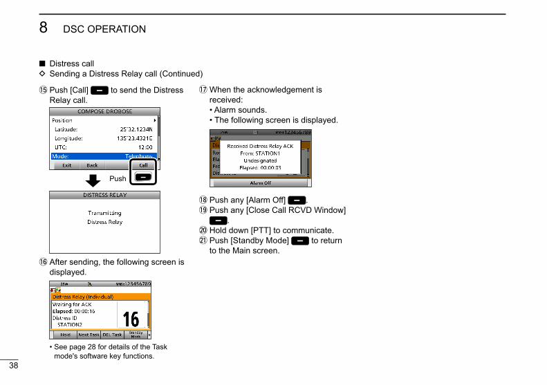
!5 Push [Call] to send the Distress Relay call.
Push
!6 After sending, the following screen is displayed.
• See page 28 for details of the Task mode's software key functions.
!7 When the acknowledgement is received:
• Alarm sounds. • The following screen is displayed.
!8 Push any [Alarm Off] .!9 Push any [Close Call RCVD Window]
.@0 Hold down [PTT] to communicate.@1 Push [Standby Mode] to return
to the Main screen.

39
8DSC OPERATION
New2001
12345678910111213141516
To transmit the distress relay call with “Distress Call Log”:You can relay a Distress call after receiving it.
Your ship
CoastStation
Distress Relay Transmission
Ship in Distress
Distress Transmission
q Push [Compose DROBOSE] to display the COMPOSE DROBOSE screen.
• To display the screen from the Menu screen: ([MENU] > Compose DROBOSE)
w Select “Message Type,” then push [ENT].
e Select the desired message type. (Example: Individual)
+Push
Rotate
When you select “All Ships” in step e, “Address” is not displayed in step r. In that case, go to step y.
r Select “Address,” then push [ENT]. t Select the desired coast station address or “Manual Input,” then push [ENT].
(Example: STATION1)
+Push
Rotate
When you select “Manual Input” in step t, push the keypad to manually enter the desired Individual ID. (p. 23)
y Select “Distress ID,” then push [ENT]. u Select the required Distress ID from the Call log list, then push [ENT].
+Push
Rotate
Distress Call Log is displayed after receiving the Distress Call.

40
8 DSC OPERATION
New2001
i Push [Call] to send the Distress Relay call.
Push
o After sending, the following screen is displayed.
• See page 28 for details of the Task mode's software key functions.
!0 When the acknowledgement is received:
• Alarm sounds. • The following screen is displayed.
!1 Push any [Alarm Off] .!2 Push any [Close Call RCVD Window]
.!3 Hold down [PTT] to communicate.!4 Push [Standby Mode] to return
to the Main screen.
Distress call D Sending a Distress Relay call (Continued)
41
8DSC OPERATION
New2001
12345678910111213141516
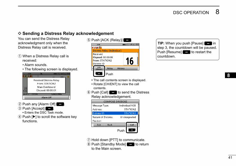
You can send the Distress Relay acknowledgment only when the Distress Relay call is received.
q When a Distress Relay call is received:
• Alarm sounds. • The following screen is displayed.
w Push any [Alarm Off] . e Push [Accept] .
• Enters the DSC Task mode. r Push [≈] to scroll the software key functions.
t Push [ACK (Relay)] .
Push
• The call contents screen is displayed. • Rotate [CH/ENT] to view the call
contents. y Push [Call] to send the Distress Relay acknowledgement.
Push
u Hold down [PTT] to communicate. i Push [Standby Mode] to return to the Main screen.
D Sending a Distress Relay acknowledgement
TIP: When you push [Pause] in step 3, the countdown will be paused. Push [Resume] to restart the countdown.

42
8 DSC OPERATION
New2001
Sending a Non-Distress callTo ensure correct operation of the DSC function, confirm you correctly set the Channel 70 squelch level. (p. 74)
NOTE:• Emergency channel (Channel 70) is
automatically selected for calling.• If Channel 70 is busy, the transceiver
stands by until the channel becomes clear.
D Sending an Individual callThe Individual call function enables you to transmit a DSC signal to only a specific coast station or ship. After transmission, wait for an acknowledgement from the receiving station.You can communicate by voice after receiving the acknowledgement ‘ACK (Able).’
q Push [Compose Non-Distress] to display the COMPOSE NON-DISTRESS screen.
Push
• To display the screen from the Menu screen: ([MENU] > Compose Non-Distress)
w Push [ENT].
Push
e Select the desired individual address, or “Manual Input,” then push [ENT].
(Example: STATION1)
+Push
Rotate
When you select “Manual Input” in step e, push the keypad to manually enter the desired Individual ID. (p. 23)

43
8DSC OPERATION
New2001
12345678910111213141516
r Select “Category,” then push [ENT]. t Select the desired option, then push [ENT].
(Example: Routine)
+Push
Rotate
When you select a coast station in step e, the voice channel is automatically specified by the coast station. Therefore, skip steps y and u, and go to step i.
y Select “Channel,” then push [ENT]. u Select the desired voice channel, then push [ENT].
+Push
RotateNOTE: After receiving the acknowledgement:• The voice channel specified in step u is
selected.• A different voice channel is selected if the
station you called cannot use the channel.
i Push [Call] to send the Individual call.
Push
o After sending, the following screen is displayed.
• See page 28 for details of the Task mode's software key functions.
!0 When the acknowledgement is received:
• Alarm sounds. • The following screen is displayed.
(Example: ACK (Able))
!1 Push any [Alarm Off] .!2 Push any [Close Call RCVD Window]
.
When you receive “ACK (Unable)” in step !0, skip step !3, and go to step !4.
!3 Hold down [PTT] to communicate.!4 Push [Standby Mode] to return
to the Main screen.

44
8 DSC OPERATION
New2001
Sending a Non-Distress calls (Continued)
When receiving an Individual call, you can send an acknowledgement (‘Able,’ ‘Unable,’ or ‘New CH’) by using the on-screen prompts.
q When an Individual call is received: • Alarm sounds. • The following screen is displayed.
w Push any [Alarm Off] . e Push [Accept] .
Push
• Enters the DSC Task mode.
r Push [≈] to scroll the software key functions. t Select your desired action.
[ACK (Able)]: Sends an acknowledgment without any changes.
[ACK (Unable)]: Sends an acknowledgment, but you cannot make a communication.
[ACK (New CH)]: Sends an acknowledgment. You can specify the Voice Communication channel.
y Push [Call] to send the Individual acknowledgement.
When you push [ACK (Unable)] in step t, skip step u, and go to step i.
u Hold down [PTT] to communicate. i Push [Standby Mode] to return to the Main screen.
D Sending an Individual acknowledgement

45
8DSC OPERATION
New2001
12345678910111213141516
D Sending an All Ships callAll ships, that have DSC transceiver, use Channel 70 as their ‘listening channel.’ When you want to announce a message to these ships within range, use the ‘All Ships Call’ function.
q Push [Compose Non-Distress] to display the COMPOSE NON-DISTRESS screen.
• To display the screen from the Menu screen: ([MENU] > Compose Non-Distress)
w Select “Message Type,” then push [ENT]. e Select “All Ships,” then push [ENT].
+Push
Rotate
r Select “Category,” then push [ENT].
t Select the desired option, then push [ENT]. (Example: Safety)
+Push
Rotate
y Select “Channel,” then push [ENT]. u Select the desired voice channel, then push [ENT].
+Push
Rotate
i Push [Call] to send the All ships call.
Push
o After sending, the following screen is displayed.
• See page 28 for details of the Task mode's software key functions.
!0 Hold down [PTT] to announce the message.
!1 Push [Standby Mode] to return to the Main screen.

46
8 DSC OPERATION
New2001
Sending a Non-Distress calls
D Sending a Group callThe Group call function allows you to transmit a DSC signal to only a specific group.
q Push [Compose Non-Distress] to display the COMPOSE NON-DISTRESS screen.
• To display the screen from the Menu screen: ([MENU] > Compose Non-Distress)
w Select “Message Type,” then push [ENT]. e Select “Group,” then push [ENT].
+Push
Rotate
r Select “Address,” then push [ENT]. t Select the desired Group address or “Manual Input,” then push [ENT].
(Example: GROUP1)
+Push
Rotate
When you select “Manual Input” in step t, push the keypad to manually enter the desired Group ID. (p. 24)
y Select “Channel,” then push [ENT]. u Select the desired voice channel, then push [ENT].
+Push
Rotate
i Push [Call] to send the Group call.
Push
o After sending, the following screen is displayed.
• See page 28 for details of the Task mode's software key functions.
!0 Hold down [PTT] to announce the message.
!1 Push [Standby Mode] to return to the Main screen.

47
8DSC OPERATION
New2001
12345678910111213141516
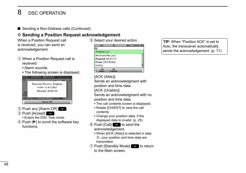
Transmit a Position Request call when you want to know a specific ship’s current position, and so on.
D Sending a Position Request call
q Push [Compose Non-Distress] to display the COMPOSE NON-DISTRESS screen.
• To display the screen from the Menu screen: ([MENU] > Compose Non-Distress)
w Select “Message Type,” then push [ENT]. e Select “Position,” then push [ENT].
+Push
Rotate
r Select “Address,” then push [ENT]. t Select the desired individual address, or “Manual Input,” then push [ENT].
(Example: STATION1)
+Push
Rotate
When you select “Manual Input” in step t, push the keypad to manually enter the desired Individual ID. (p. 23)
y Push [Call] to send the Position Request call.
Push
u After sending, the following screen is displayed.
• See page 28 for details of the Task mode's software key functions.
i When the acknowledgement is received:
• Alarm sounds. • The following screen is displayed.
o Push any [Alarm Off] .!0 Push any [Close Call RCVD Window]
. • Rotate [CH/ENT] to view the call
contents (position data is included).!1 Push [Standby Mode] to return
to the Main screen.
48
8 DSC OPERATION
New2001
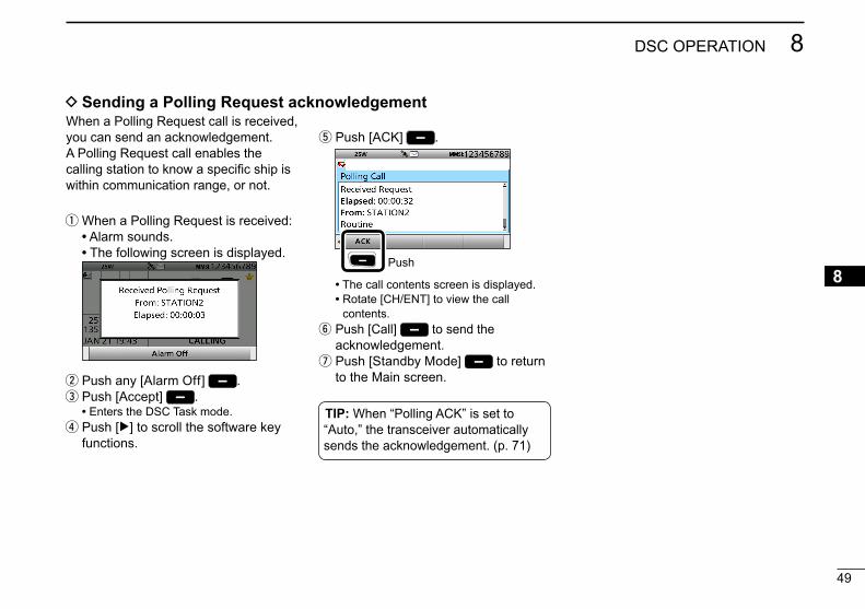
Sending a Non-Distress calls (Continued)
q When a Position Request call is received:
• Alarm sounds. • The following screen is displayed.
w Push any [Alarm Off] . e Push [Accept] .
• Enters the DSC Task mode. r Push [≈] to scroll the software key functions.
D Sending a Position Request acknowledgement t Select your desired action.
[ACK (Able)]: Sends an acknowledgment with position and time data.
[ACK (Unable)]: Sends an acknowledgment with no position and time data.
• The call contents screen is displayed. • Rotate [CH/ENT] to view the call
contents. • Change your position data, if the
displayed data is invalid. (p. 25) y Push [Call] to send the acknowledgement.
• When [ACK (Able)] is selected in step t, your position and time data are transmitted.
u Push [Standby Mode] to return to the Main screen.
TIP: When “Position ACK” is set to Auto, the transceiver automatically sends the acknowledgement. (p. 71)
When a Position Request call is received, you can send an acknowledgement.
49
8DSC OPERATION
New2001
12345678910111213141516
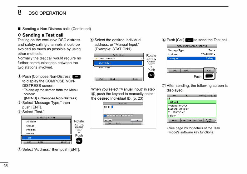
q When a Polling Request is received: • Alarm sounds. • The following screen is displayed.
w Push any [Alarm Off] . e Push [Accept] .
• Enters the DSC Task mode. r Push [≈] to scroll the software key functions.
t Push [ACK] .
Push
• The call contents screen is displayed. • Rotate [CH/ENT] to view the call
contents. y Push [Call] to send the acknowledgement. u Push [Standby Mode] to return to the Main screen.
D Sending a Polling Request acknowledgement
TIP: When “Polling ACK” is set to “Auto,” the transceiver automatically sends the acknowledgement. (p. 71)
When a Polling Request call is received, you can send an acknowledgement.A Polling Request call enables the calling station to know a specific ship is within communication range, or not.
50
8 DSC OPERATION
New2001
Sending a Non-Distress calls (Continued)
D Sending a Test callTesting on the exclusive DSC distress and safety calling channels should be avoided as much as possible by using other methods.Normally the test call would require no further communications between the two stations involved.
q Push [Compose Non-Distress] to display the COMPOSE NON-DISTRESS screen.
• To display the screen from the Menu screen: ([MENU] > Compose Non-Distress)
w Select “Message Type,” then push [ENT]. e Select “Test.”
+Push
Rotate
r Select “Address,” then push [ENT].
t Select the desired Individual address, or “Manual Input.”
(Example: STATION1)
+Push
Rotate
When you select “Manual Input” in step t, push the keypad to manually enter the desired Individual ID. (p. 23)
y Push [Call] to send the Test call.
Push
u After sending, the following screen is displayed.
• See page 28 for details of the Task mode's software key functions.

51
8DSC OPERATION
New2001
12345678910111213141516
i When the acknowledgement is received:
• Alarm sounds. • The following screen is displayed.
o Push any [Alarm Off] .!0 Push [Accept] . • Enters the DSC Task mode.!1 Rotate [CH/ENT] to view the
received message log.!2 Push [Standby Mode] to return
to the Main screen.
q When a Test call is received: • Alarm sounds.
w Push any [Alarm Off] e Push [Accept] .
• Enters the DSC Task mode. r Push [≈] to scroll the software key functions.
D Sending a Test call acknowledgement
TIP: When “Test ACK” is set to “Auto,” the transceiver automatically sends the acknowledgement. (p. 71)
When a Test call is received, you can send an acknowledgement. t Push [ACK] .
Push
• The call contents screen is displayed. • Rotate [CH/ENT] to view the call
contents. y Push [Call] to send the acknowledgement. u Push [Standby Mode] to return to the Main screen.
52
8 DSC OPERATION
New2001
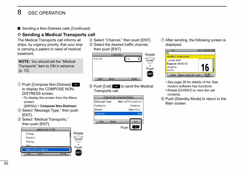
Sending a Non-Distress calls (Continued)
q Push [Compose Non-Distress] to display the COMPOSE NON-DISTRESS screen.
• To display the screen from the Menu screen: ([MENU] > Compose Non-Distress)
w Select “Message Type,” then push [ENT]. e Select “Medical Transports,” then push [ENT].
+Push
Rotate
r Select “Channel,” then push [ENT]. t Select the desired traffic channel, then push [ENT].
+Push
Rotate
y Push [Call] to send the Medical Transports call.
Push
u After sending, the following screen is displayed.
• See page 28 for details of the Task mode's software key functions.
• Rotate [CH/ENT] to view the call contents.
i Push [Standby Mode] to return to the Main screen.
D Sending a Medical Transports callThe Medical Transports call informs all ships, by urgency priority, that your ship is carrying a patient in need of medical treatment.
NOTE: You should set the “Medical Transports” item to ON in advance. (p. 72)

53
8DSC OPERATION
New2001
12345678910111213141516
q Push [Compose Non-Distress] to display the COMPOSE NON-DISTRESS screen.
• To display the screen from the Menu screen: ([MENU] > Compose Non-Distress)
w Select “Message Type,” then push [ENT]. e Select “Ships and Aircraft,” then push [ENT].
+Push
Rotate
D Sending a Ships and Aircraft call r Select “Channel,” then push [ENT]. t Select the desired traffic channel, then push [ENT].
+Push
Rotate
y Push [Call] to send the Ships and Aircraft call.
Push
u After sending, the following screen is displayed.
• See page 28 for details of the Task mode's software key functions.
• Rotate [CH/ENT] to view the call contents.
i Push [Standby Mode] to return to the Main screen.
The Ships and Aircraft call informs all ships that your ship is a neutral (not a participant) in armed conflict. Be sure to send the call BEFORE entering an area of armed conflict.
NOTE: You should set the “Ships and Aircraft” item to ON in advance. (p. 72)
54
8 DSC OPERATION
New2001
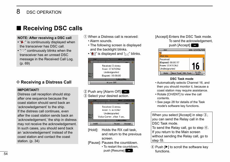
q When a Distress call is received: • Alarm sounds. • The following screen is displayed
and the backlight blinks. • “ ” is displayed and “ ” blinks.
w Push any [Alarm Off] . e Select your desired action.
[Hold]: Holds the RX call task, and return to the previous screen.
[Pause]: Pauses the countdown. • To restart the countdown,
push [Resume] .
Receiving DSC calls
IMPORTANT!Distress call reception should stop after one sequence because the coast station should send back an ‘acknowledgement’ to the ship.If the distress call continues, even after the coast station sends back an ‘acknowledgement,’ the ship in distress may not receive the acknowledgement. In such cases, you should send back an ‘acknowledgement’ instead of the coast station and contact the coast station. (p. 34)
[Accept]: Enters the DSC Task mode. To send the acknowledgement, push [Accept] .
DSC Task mode • Automatically selects Channel 16, and
then you should monitor it, because a coast station may require assistance.
• Rotate [CH/ENT] to view the call contents.
• See page 28 for details of the Task mode's software key functions.
When you select [Accept] in step e, you can send the Relay call in the DSC Task mode.To send the Relay call, go to step r.If you return to the Main screen without sending the Relay call, go to step !0.
r Push [≈] to scroll the software key functions.
NOTE: After receiving a DSC call• “ ” is continuously displayed when
the transceiver has DSC call.• “ ” continuously blinks when the
transceiver has an unread DSC message in the Received Call Log. (p. 69)
D Receiving a Distress Call

55
8DSC OPERATION
New2001
12345678910111213141516
D Receiving a Distress acknowledgement q When a Distress acknowledgement sent to another ship is received:
• Alarm sounds. • The following screen is displayed
and the backlight blinks. • “ ” is displayed.
w Push any [Alarm Off] . e Push any [Close Call RCVD Window]
.
• Enters the DSC Task mode.
DSC Task mode • Automatically selects Channel 16, and
then monitor it, because a coast station may require assistance.
• Rotate [CH/ENT] to view the call contents.
• See page 28 for details of the Task mode's software key functions.
r Push [Standby Mode] to return to the Main screen.
TIP: See page 34 for details of sending an acknowledgement.
t Push [Relay].
Push
y When the confirmation screen is displayed, push [OK]. u Select “Address,” then push [ENT]. i Select the desired Individual address, or “Manual Input,” then push [ENT].
+Push
Rotate
o Push [Call] to send the Relay call.!0 Push [Standby Mode] to return
to the Main screen.

56
8 DSC OPERATION
New2001
Receiving DSC calls (Continued)
q When a Distress Cancel call is received:
• Alarm sounds. • The following screen is displayed
and the backlight blinks. • “ ” is displayed and “ ” blinks.
w Push any [Alarm Off] . e Select your desired action.
[Hold]: Holds the RX call task, and return to the previous screen.
[Pause]: Pauses the countdown. • To restart the countdown,
push [Resume] . [Accept]: Enters the DSC Task mode.
DSC Task mode • Automatically selects Channel 16, and
then you should monitor it, because a coast station may require assistance.
• Rotate [CH/ENT] to view the call contents.
• See page 28 for details of the Task mode's software key functions.
r Push [Standby Mode] to return to the Main screen.
D Receiving a Distress Relay call q When a Distress Relay call is received:
• Alarm sounds. • The following screen is displayed
and the backlight blinks. • “ ” is displayed and “ ” blinks.
w Push any [Alarm Off] . e Select your desired action.
[Hold]: Holds the RX call task, and return to the previous screen.
[Pause]: Pauses the countdown. • To restart the countdown,
push [Resume] .
D Receiving a Distress Cancel call
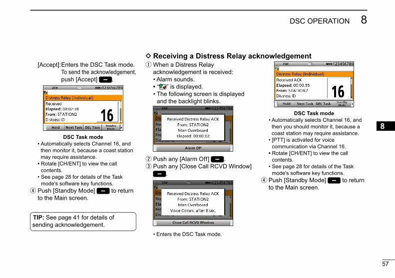
57
8DSC OPERATION
New2001
12345678910111213141516
[Accept]: Enters the DSC Task mode. To send the acknowledgement, push [Accept] .
DSC Task mode • Automatically selects Channel 16, and
then monitor it, because a coast station may require assistance.
• Rotate [CH/ENT] to view the call contents.
• See page 28 for details of the Task mode's software key functions.
r Push [Standby Mode] to return to the Main screen.
q When a Distress Relay acknowledgement is received:
• Alarm sounds. • “ ” is displayed. • The following screen is displayed
and the backlight blinks.
w Push any [Alarm Off] . e Push any [Close Call RCVD Window]
.
• Enters the DSC Task mode.
D Receiving a Distress Relay acknowledgement
DSC Task mode • Automatically selects Channel 16, and
then you should monitor it, because a coast station may require assistance.
• [PTT] is activated for voice communication via Channel 16.
• Rotate [CH/ENT] to view the call contents.
• See page 28 for details of the Task mode's software key functions.
r Push [Standby Mode] to return to the Main screen.
TIP: See page 41 for details of sending acknowledgement.

58
8 DSC OPERATION
New2001
Receiving DSC calls (Continued)
q When an Individual call is received: • Alarm sounds. • The following screen is displayed
and the backlight blinks. • “ ” is displayed and “ ” blinks.
w Push any [Alarm Off] . e Select your desired action.
[Hold]: Holds the RX call task, and return to the previous screen.
[ACK (Able)]: Sends an acknowledgment
without any changes. [Accept]: Enters the DSC Task mode.
To send the acknowledgement, push [Accept] .
DSC Task mode • Rotate [CH/ENT] to view the call
contents. • See page 28 for details of the Task
mode's software key functions.
When you select [Accept] in step e, you can send an acknowledgement in the DSC Task mode. To send the acknowledgement, go to step r.If you return to the Main screen without sending the acknowledgement, go to step i.
NOTE: When the “Individual ACK” item is set to “Auto,” the transceiver automatically sends an acknowledgement. Both the TX and RX calls are stored in the Transmitted and Received Call Logs. (pp. 69, 70)
r Push [≈] to scroll the software key functions.
t Push the desired key to select an acknowledgement option.
y Push [Call] to send the Individual acknowledgement. u Depending on the option selected in step t, hold down [PTT] to communicate. i Push [Standby Mode] to return to the Main screen.
D Receiving an Individual call
TIP: When you send the acknowledgement, select one of three options, depending on your situation. See page 44 for details of the Individual acknowledgement procedures.

59
8DSC OPERATION
New2001
12345678910111213141516
When receiving “ACK (Able)”:You can make voice communication on the channel that you specified when you sent the call.
q When an Individual acknowledgement “ACK (Able)” is received:
• Alarm sounds. • The following screen is displayed
and the backlight blinks. • “ ” is displayed.
w Push any [Alarm Off] .
D Receiving an Individual acknowledgement
e Push any [Close Call RCVD Window] .
• Enters the DSC Task mode.
DSC Task mode • Automatically selects the channel that
you specified when you sent the call for voice communication.
• Rotate [CH/ENT] to view the call contents.
• See page 28 for details of the Task mode's software key functions.
r Hold down [PTT] to communicate. t Push [Standby Mode] to return to the Main screen.

60
8 DSC OPERATION
New2001
Receiving DSC calls D Receiving an Individual acknowledgement (Continued)
e Push any [Close Call RCVD Window] .
• Enters the DSC Task mode.
DSC Task mode • Rotate [CH/ENT] to view the call
contents. • See page 28 for details of the Task
mode's software key functions. r Push [Standby Mode] to return to the Main screen.
When receiving “ACK (New CH)”:You can make voice communication on the channel that is proposed by the called station.
q When an Individual acknowledgement “ACK (New CH)” is received:
• Alarm sounds. • The following screen is displayed
and the backlight blinks. • “ ” is displayed.
w Push any [Alarm Off] .
When receiving “ACK (Unable)”:You cannot make the voice communication.
q When an Individual acknowledgement “ACK (Unable)” is received:
• Alarm sounds. • “ ” is displayed. • The following screen is displayed
and the backlight blinks.
w Push any [Alarm Off] .
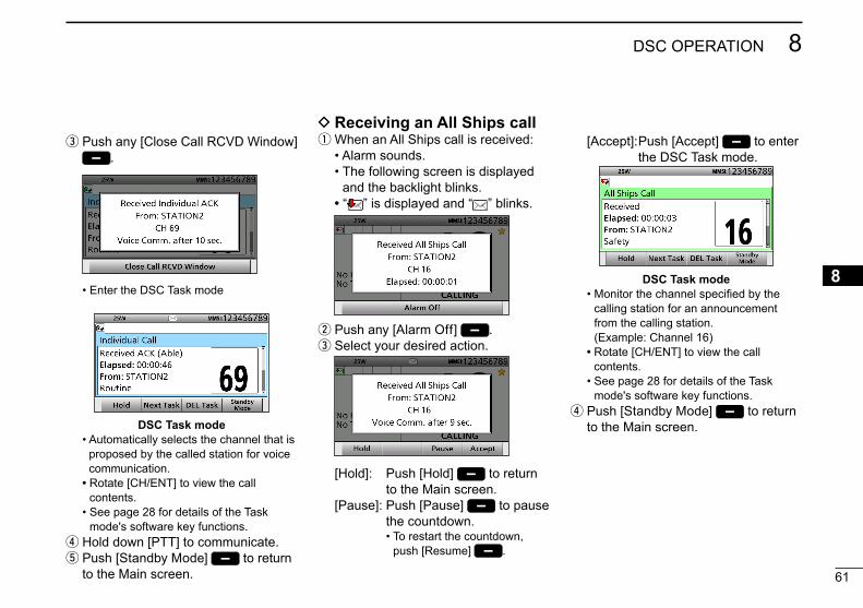
61
8DSC OPERATION
New2001
12345678910111213141516
e Push any [Close Call RCVD Window] .
• Enter the DSC Task mode
DSC Task mode • Automatically selects the channel that is
proposed by the called station for voice communication.
• Rotate [CH/ENT] to view the call contents.
• See page 28 for details of the Task mode's software key functions.
r Hold down [PTT] to communicate. t Push [Standby Mode] to return to the Main screen.
D Receiving an All Ships call q When an All Ships call is received:
• Alarm sounds. • The following screen is displayed
and the backlight blinks. • “ ” is displayed and “ ” blinks.
w Push any [Alarm Off] . e Select your desired action.
[Hold]: Push [Hold] to return to the Main screen.
[Pause]: Push [Pause] to pause the countdown. • To restart the countdown,
push [Resume] .
[Accept]: Push [Accept] to enter the DSC Task mode.
DSC Task mode • Monitor the channel specified by the
calling station for an announcement from the calling station. (Example: Channel 16)
• Rotate [CH/ENT] to view the call contents.
• See page 28 for details of the Task mode's software key functions.
r Push [Standby Mode] to return to the Main screen.
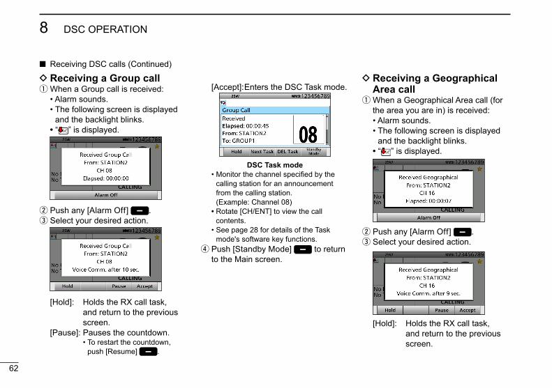
62
8 DSC OPERATION
New2001
D Receiving a Group call q When a Group call is received:
• Alarm sounds. • The following screen is displayed
and the backlight blinks. • “ ” is displayed.
w Push any [Alarm Off] . e Select your desired action.
[Hold]: Holds the RX call task, and return to the previous screen.
[Pause]: Pauses the countdown. • To restart the countdown,
push [Resume] .
D Receiving a Geographical Area call q When a Geographical Area call (for the area you are in) is received:
• Alarm sounds. • The following screen is displayed
and the backlight blinks. • “ ” is displayed.
w Push any [Alarm Off] . e Select your desired action.
[Hold]: Holds the RX call task, and return to the previous screen.
Receiving DSC calls (Continued)
[Accept]: Enters the DSC Task mode.
DSC Task mode • Monitor the channel specified by the
calling station for an announcement from the calling station. (Example: Channel 08)
• Rotate [CH/ENT] to view the call contents.
• See page 28 for details of the Task mode's software key functions.
r Push [Standby Mode] to return to the Main screen.

63
8DSC OPERATION
New2001
12345678910111213141516
q When a Position Request call is received:
• Alarm sounds. • The following screen is displayed
and the backlight blinks. • “ ” is displayed and “ ” blinks.
w Push any [Alarm Off] . e Select your desired action.
D Receiving a Position Request Call [Hold]:
Holds the RX call task, and return to the previous screen.
[ACK (Unable)]: Sends an acknowledgment with no position and time data.
[ACK (Able)]: Sends an acknowledgment with position and time data.
[Accept]: Enters the DSC Task mode.
DSC Task mode • Rotate [CH/ENT] to view the call
contents. • See page 28 for details of the Task
mode's software key functions. r Push [Standby Mode] to return to the Main screen.
NOTE: When “Position ACK” is set to “Auto,” the transceiver automatically replies to the call. Both the TX and RX calls are stored in the Transmitted and Received Call Logs. (Default: Manual)
[Pause]: Pauses the countdown. • To restart the countdown,
push [Resume] . [Accept]: Enters the DSC Task mode.
DSC Task mode • Monitor the channel specified by the
calling station for an announcement from the calling station. (Example: Channel 16)
• Rotate [CH/ENT] to view the call contents.
• See page 28 for details of the Task mode's software key functions.
r Push [Standby Mode] to return to the Main screen.
TIP: See page 48 for details of sending an acknowledgement.

64
8 DSC OPERATION
New2001
Receiving DSC calls (Continued)
q When a Position Request acknowledgement is received:
• Alarm sounds. • The following screen is displayed
and the backlight blinks. • “ ” is displayed.
w Push any [Alarm Off] . e Push any [Close Call RCVD Window]
.
• Enters the DSC Task mode.
D Receiving a Position Report call q When a Position Report call is received:
• Alarm sounds. • The following screen is displayed
and the backlight blinks. • “ ” is displayed and “ ” blinks.
w Push any [Alarm Off] . e Select your desired action.
[Hold]: Holds the RX call task, and return to the previous screen.
[ACK]: Sends an acknowledgment. [Accept]: Enters the DSC Task mode.
D Receiving a Position Request acknowledgement
DSC Task mode • Rotate [CH/ENT] to view the call
contents. • See page 28 for details of the Task
mode's software key functions. r Push [Standby Mode] to return to the Main screen.
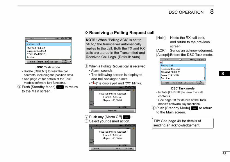
65
8DSC OPERATION
New2001
12345678910111213141516
q When a Polling Request call is received: • Alarm sounds. • The following screen is displayed
and the backlight blinks. • “ ” is displayed and “ ” blinks.
w Push any [Alarm Off] . e Select your desired action.
DSC Task mode • Rotate [CH/ENT] to view the call
contents, including the position data. • See page 28 for details of the Task
mode's software key functions. r Push [Standby Mode] to return to the Main screen.
D Receiving a Polling Request call [Hold]: Holds the RX call task,
and return to the previous screen.
[ACK ]: Sends an acknowledgment. [Accept]: Enters the DSC Task mode.
DSC Task mode • Rotate [CH/ENT] to view the call
contents. • See page 28 for details of the Task
mode's software key functions. r Push [Standby Mode] to return to the Main screen.
NOTE: When “Polling ACK” is set to “Auto,” the transceiver automatically replies to the call. Both the TX and RX calls are stored in the Transmitted and Received Call Logs. (Default: Auto)
TIP: See page 49 for details of sending an acknowledgement.
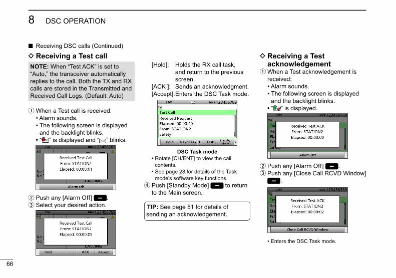
66
8 DSC OPERATION
New2001
q When a Test call is received: • Alarm sounds. • The following screen is displayed
and the backlight blinks. • “ ” is displayed and “ ” blinks.
w Push any [Alarm Off] . e Select your desired action.
D Receiving a Test acknowledgement q When a Test acknowledgement is received:
• Alarm sounds. • The following screen is displayed
and the backlight blinks. • “ ” is displayed.
w Push any [Alarm Off] . e Push any [Close Call RCVD Window]
.
• Enters the DSC Task mode.
Receiving DSC calls (Continued)
[Hold]: Holds the RX call task, and return to the previous screen.
[ACK ]: Sends an acknowledgment. [Accept]: Enters the DSC Task mode.
DSC Task mode • Rotate [CH/ENT] to view the call
contents. • See page 28 for details of the Task
mode's software key functions. r Push [Standby Mode] to return to the Main screen.
NOTE: When “Test ACK” is set to “Auto,” the transceiver automatically replies to the call. Both the TX and RX calls are stored in the Transmitted and Received Call Logs. (Default: Auto)
D Receiving a Test call
TIP: See page 51 for details of sending an acknowledgement.
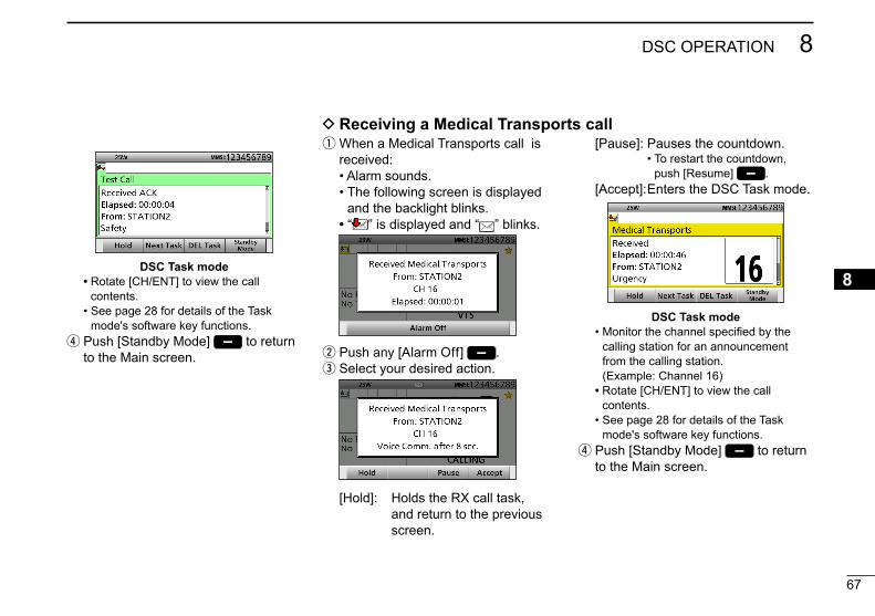
67
8DSC OPERATION
New2001
12345678910111213141516
DSC Task mode • Rotate [CH/ENT] to view the call
contents. • See page 28 for details of the Task
mode's software key functions. r Push [Standby Mode] to return to the Main screen.
q When a Medical Transports call is received:
• Alarm sounds. • The following screen is displayed
and the backlight blinks. • “ ” is displayed and “ ” blinks.
w Push any [Alarm Off] . e Select your desired action.
[Hold]: Holds the RX call task, and return to the previous screen.
[Pause]: Pauses the countdown. • To restart the countdown,
push [Resume] . [Accept]: Enters the DSC Task mode.
DSC Task mode • Monitor the channel specified by the
calling station for an announcement from the calling station. (Example: Channel 16)
• Rotate [CH/ENT] to view the call contents.
• See page 28 for details of the Task mode's software key functions.
r Push [Standby Mode] to return to the Main screen.
D Receiving a Medical Transports call

68
8 DSC OPERATION
New2001
q When a Ships and Aircraft call is received:
• Alarm sounds. • The following screen is displayed
and the backlight blinks. • “ ” is displayed and “ ” blinks.
w Push any [Alarm Off] . e Select your desired action.
[Hold]: Holds the RX call task, and return to the previous screen.
[Pause]: Pauses the countdown. • To restart the countdown,
push [Resume] . [Accept]: Enters the DSC Task mode.
DSC Task mode • Monitor the channel specified by the
calling station for an announcement from the calling station. (Example: Channel 16)
• Rotate [CH/ENT] to view the call contents.
• See page 28 for details of the Task mode's software key functions.
r Push [Standby Mode] to return to the Main screen.
D Receiving a Ships and Aircraft call Receiving DSC calls (Continued)

69
8DSC OPERATION
New2001
12345678910111213141516
D Distress message q Push [DSC Log] to display the RCVD CALL LOG screen.
• To display the screen from the Menu screen: ( [MENU] > DSC Log > Received Call Log)
w Select “Distress,” then push [ENT]. e Select the desired message, then push [ENT].
+Push
Rotate
r Rotate [CH/ENT] to view the contents.
• To view another message, push [CLR] to return to the previous screen. And then, select the desired message.
t Push [Exit] to return to the Main screen.
Received Call log D Other messages q Push [DSC Log] to display the RCVD CALL LOG screen.
• To display the screen from the Menu screen: ( [MENU] > DSC Log > Received Call Log)
w Select “Others,” then push [ENT]. e Select the desired message, then push [ENT].
+Push
Rotate
r Rotate [CH/ENT] to view the contents.
• To view another message, push [CLR] to return to the previous screen. And then, select the desired message.
t Push [Exit] to return to the Main screen.
The transceiver automatically stores up to 50 distress messages and 50 other messages, and they can be used as a supplement to your logbook.
• When there is an unread DSC message, “ ” blinks on the information area of the LCD.
• “ ” is displayed when there are unread DSC messages.
• “ ” is displayed when there are no unread DSC messages.
• No icon is displayed when there are no DSC messages.
• Distress messages are stored in “Distress.”
Software key functions in the RCVD CALL LOG screen:[Exit]: Push to return to the Main screen.[Back]: Push to return to the previous
screen.[Print]: Push to print out the selected
message when a printer is connected to the transceiver.
[Enter]: Push to go to the next screen.[Delete]: Push to delete the selected
message.
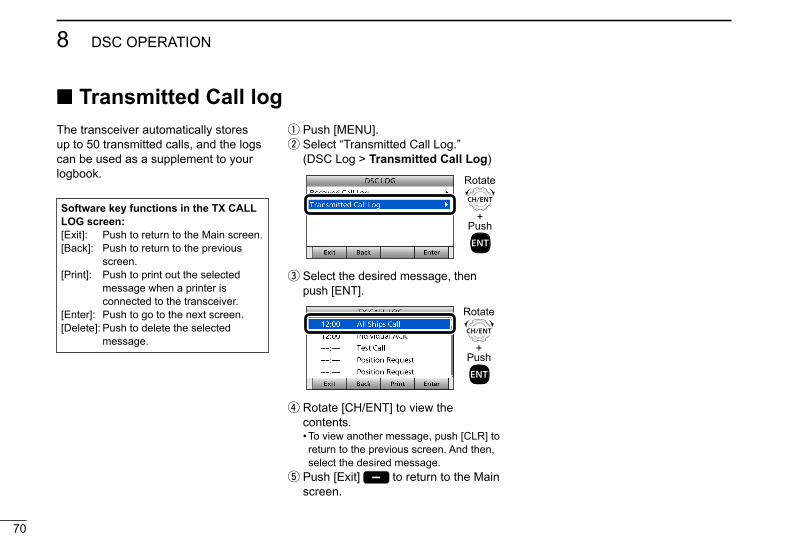
70
8 DSC OPERATION
New2001
Transmitted Call logThe transceiver automatically stores up to 50 transmitted calls, and the logs can be used as a supplement to your logbook.
q Push [MENU]. w Select “Transmitted Call Log.”
( DSC Log > Transmitted Call Log)
+Push
Rotate
e Select the desired message, then push [ENT].
+Push
Rotate
r Rotate [CH/ENT] to view the contents.
• To view another message, push [CLR] to return to the previous screen. And then, select the desired message.
t Push [Exit] to return to the Main screen.
Software key functions in the TX CALL LOG screen:[Exit]: Push to return to the Main screen.[Back]: Push to return to the previous
screen.[Print]: Push to print out the selected
message when a printer is connected to the transceiver.
[Enter]: Push to go to the next screen.[Delete]: Push to delete the selected
message.
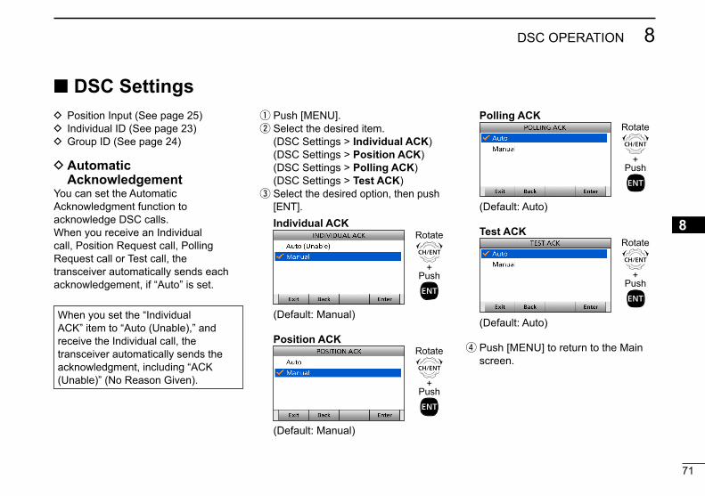
71
8DSC OPERATION
New2001
12345678910111213141516
D Automatic Acknowledgement
You can set the Automatic Acknowledgment function to acknowledge DSC calls.When you receive an Individual call, Position Request call, Polling Request call or Test call, the transceiver automatically sends each acknowledgement, if “Auto” is set.
DSC Settings D Position Input (See page 25) D Individual ID (See page 23) D Group ID (See page 24)
When you set the “Individual ACK” item to “Auto (Unable),” and receive the Individual call, the transceiver automatically sends the acknowledgment, including “ACK (Unable)” (No Reason Given).
q Push [MENU]. w Select the desired item.
( DSC Settings > Individual ACK) ( DSC Settings > Position ACK) ( DSC Settings > Polling ACK) ( DSC Settings > Test ACK)
e Select the desired option, then push [ENT].
Individual ACK
+Push
Rotate
(Default: Manual)
Position ACK
+Push
Rotate
(Default: Manual)
Polling ACK
+Push
Rotate
(Default: Auto)
Test ACK
+Push
Rotate
(Default: Auto)
r Push [MENU] to return to the Main screen.

72
8 DSC OPERATION
New2001
D Setting the “Medical Transports” item display option
You can select whether the “Medical Transports” item is displayed in the COMPOSE NON-DISTRESS screen or not.
q Push [MENU]. w Select “Medical Transports,” then push [ENT].
( DSC Settings > Medical Transports)
+Push
Rotate
e Select the desired option, then push [ENT].
• On: Displayed in the COMPOSE NON-DISTRESS screen.
• Off: Not displayed in the COMPOSE NON-DISTRESS screen. (Default)
r Push [MENU] to return to the Main screen.
D Setting the “Ships and Aircraft” item display option
You can select whether the “Ships and Aircraft” item is displayed in the COMPOSE NON-DISTRESS screen or not.
q Push [MENU]. w Select “Ships and Aircraft,” then push [ENT].
( DSC Settings > Ships and Aircraft)
+Push
Rotate
e Select the desired option, then push [ENT].
• On: Displayed in the COMPOSE NON-DISTRESS screen.
• Off: Not displayed in the COMPOSE NON-DISTRESS screen. (Default)
r Push [MENU] to return to the Main screen.
D Setting the 10 Second DelaySelect whether or not the transceiver automatically switches to Channel 16, 10 seconds after receiving a Distress call.By regulation, after receiving a Distress call, the transceiver normally switches the operating channel to Channel 16. However, when this setting is OFF, the transceiver remains on the operating channel to continue the current communication, even after receiving a Distress call.
DSC Settings (Continued)

73
8DSC OPERATION
New2001
12345678910111213141516
D Setting the Alarm Status• Safety• RoutineSelect whether or not to sound an alarm when receiving the Safety or Routine DSC call.
q Push [MENU]. w Select the desired item, then push [ENT].
( DSC Settings > Alarm Status > Safety)
( DSC Settings > Alarm Status > Routine)
(Example: Safety)
+Push
Rotate
e Select the desired option, then push [ENT].
• On: Alarm sounds. (Default) • Off: Alarm does not sound.
r Push [MENU] to return to the Main screen.
q Push [MENU]. w Select “10 Second Delay,” then push [ENT].
( DSC Settings > 10 Second Delay)
+Push
Rotate
e Select the desired option, then push [ENT].
• On: After receiving a DSC call, the transceiver remains on the current operating channel for 10 seconds. After that, the transceiver automatically switches to the specified channel. (Default)
• Off: The transceiver remains on the operating channel even after receiving a DSC call.
r Push [MENU] to return to the Main screen.
• WarningSelect whether or not to sound an alarm:• When no MMSI code is entered.• When the position data has not been
updated for 10 minutes.• When the position data has not been
manually updated for 4 hours.• After the invalid GPS position data or
manually entered position data has not been updated for 23.5 hours.
q Push [MENU]. w Select “Warning,” then push [ENT].
( DSC Settings > Alarm Status > Warning)
+Push
Rotate
e Select the desired option, then push [ENT].
• On: Alarm sounds. (Default) • Off: Alarm does not sound.
r Push [MENU] to return to the Main screen.
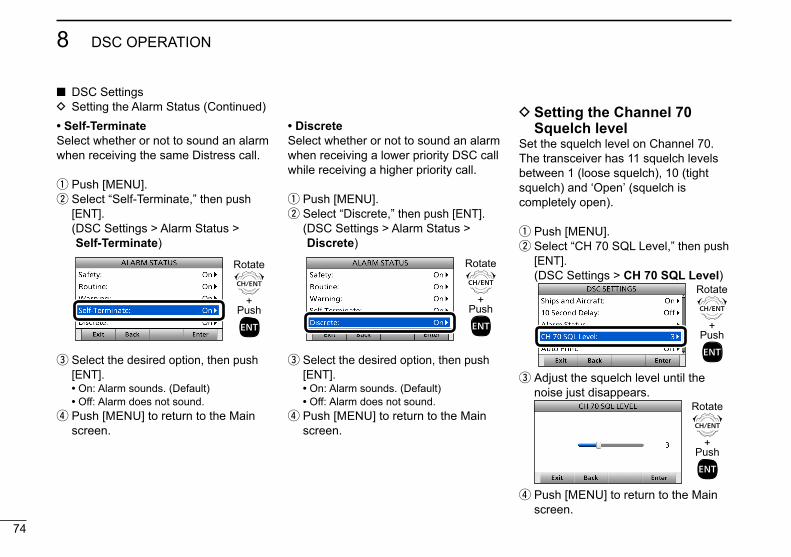
74
8 DSC OPERATION
New2001
DSC Settings D Setting the Alarm Status (Continued)
• Self-TerminateSelect whether or not to sound an alarm when receiving the same Distress call.
q Push [MENU]. w Select “Self-Terminate,” then push [ENT].
( DSC Settings > Alarm Status > Self-Terminate)
+Push
Rotate
e Select the desired option, then push [ENT].
• On: Alarm sounds. (Default) • Off: Alarm does not sound.
r Push [MENU] to return to the Main screen.
• DiscreteSelect whether or not to sound an alarm when receiving a lower priority DSC call while receiving a higher priority call.
q Push [MENU]. w Select “Discrete,” then push [ENT].
( DSC Settings > Alarm Status > Discrete)
+Push
Rotate
e Select the desired option, then push [ENT].
• On: Alarm sounds. (Default) • Off: Alarm does not sound.
r Push [MENU] to return to the Main screen.
D Setting the Channel 70 Squelch level
Set the squelch level on Channel 70.The transceiver has 11 squelch levels between 1 (loose squelch), 10 (tight squelch) and ʻOpenʼ (squelch is completely open).
q Push [MENU]. w Select “CH 70 SQL Level,” then push [ENT].
( DSC Settings > CH 70 SQL Level)
+Push
Rotate
e Adjust the squelch level until the noise just disappears.
+Push
Rotate
r Push [MENU] to return to the Main screen.

75
8DSC OPERATION
New2001
12345678910111213141516
D Auto PrintSelect whether or not to enable the Automatic Print Out function when a DSC call is received.The received DSC call content is printed out if a printer is connected to the transceiver.
q Push [MENU]. w Select “Auto Print,” then push [ENT].
( DSC Settings > Auto Print)
+Push
Rotate
e Select the desired option, then push [ENT].
• On: The received DSC call content is printed out.
• Off: The received DSC call content is not printed out. (Default)
r Push [MENU] to return to the Main screen.
D DSC Loop TestThe DSC loop test function sends transmit DSC signals to the receive AF circuit to compare and check the TX and RX signals at the AF level.
q Push [MENU]. w Select “DSC Loop Test,” then push [ENT].
( DSC Settings > DSC Loop Test)
+Push
Rotate
e Push [ENT] to start the DSC loop test.
Push
• When the transmit DSC and receive DSC signals are matched, “OK” is displayed.
r Push [MENU] to return to the Main screen.
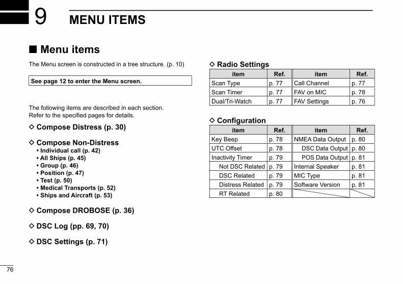
76
New2001New2001
MENU ITEMS9 Menu items
The Menu screen is constructed in a tree structure. (p. 10)
See page 12 to enter the Menu screen.
The following items are described in each section.Refer to the specified pages for details.
D Compose Distress (p. 30)
D Compose Non-Distress • Individual call (p. 42) • All Ships (p. 45) • Group (p. 46) • Position (p. 47) • Test (p. 50) • Medical Transports (p. 52) • Ships and Aircraft (p. 53)
D Compose DROBOSE (p. 36)
D DSC Log (pp. 69, 70)
D DSC Settings (p. 71)
D Radio Settingsitem Ref. item Ref.
Scan Type p. 77 Call Channel p. 77Scan Timer p. 77 FAV on MIC p. 78Dual/Tri-Watch p. 77 FAV Settings p. 76
D Configurationitem Ref. item Ref.
Key Beep p. 78 NMEA Data Output p. 80UTC Offset p. 78 DSC Data Output p. 80Inactivity Timer p. 79 POS Data Output p. 81 Not DSC Related p. 79 Internal Speaker p. 81 DSC Related p. 79 MIC Type p. 81 Distress Related p. 79 Software Version p. 81 RT Related p. 80
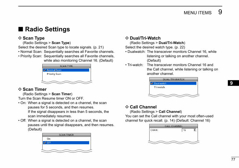
77
9MENU ITEMS
New2001
12345678910111213141516
New2001
Radio Settings D Scan Type
(Radio Settings > Scan Type)Select the desired Scan type to locate signals. (p. 21)• Normal Scan: Sequentially searches all Favorite channels.• Priority Scan: Sequentially searches all Favorite channels,
while also monitoring Channel 16. (Default)
D Scan Timer (Radio Settings > Scan Timer)Turn the Scan Resume timer ON or OFF.• On: When a signal is detected on a channel, the scan
pauses for 5 seconds, and then resumes. If the signal disappears in less than 5 seconds, the scan immediately resumes.
• Off: When a signal is detected on a channel, the scan pauses until the signal disappears, and then resumes. (Default)
D Dual/Tri-Watch (Radio Settings > Dual/Tri-Watch)Select the desired watch type. (p. 22)• Dualwatch: The transceiver monitors Channel 16, while
listening or talking on another channel. (Default)
• Tri-watch: The transceiver monitors Channel 16 and the Call channel, while listening or talking on another channel.
D Call Channel (Radio Settings > Call Channel)You can set the Call channel with your most often-used channel for quick recall. (p. 14) (Default: Channel 16)

78
9 MENU ITEMS
New2001
Radio Settings (Continued) D FAV on MIC
(Radio Settings > FAV on MIC)Turn the FAV on MIC function ON or OFF.• On: Pushing [∫] or [√] on the supplied microphone scrolls
up and down through only the Favorite channels. (Default)
• Off: Pushing [∫] or [√] on the supplied microphone scrolls up and down through all channels.
D FAV Settings (Radio Settings > FAV Settings)Set the Favorite channel settings.• Set All Channels: Sets all channels as Favorite channels.• Clear All Channels: Clears all Favorite channels.• Set Default: Returns to the default setting.
Configuration D Key Beep
(Configuration > Key Beep)Turn the Key Beep function ON or OFF.• On: Sounds a beep when pushing a key. (Default)• Off: Does not sound a beep when pushing a key for silent
operation.
D UTC Offset (Configuration > UTC Offset)Set the offset time between UTC (Universal Time Coordinated) and your local time to between –14:00 and +14:00 (in 1 minute steps). (Default: 00:00)
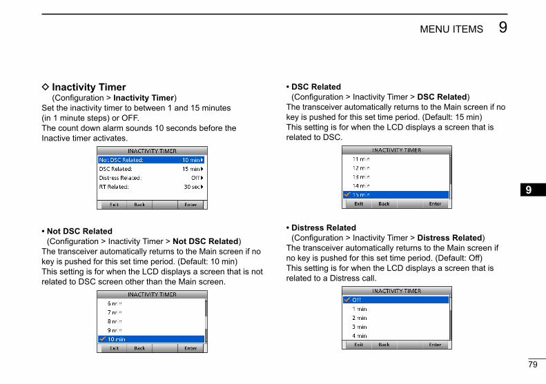
79
9MENU ITEMS
New2001
12345678910111213141516
D Inactivity Timer (Configuration > Inactivity Timer)Set the inactivity timer to between 1 and 15 minutes (in 1 minute steps) or OFF.The count down alarm sounds 10 seconds before the Inactive timer activates.
• Not DSC Related (Configuration > Inactivity Timer > Not DSC Related)
The transceiver automatically returns to the Main screen if no key is pushed for this set time period. (Default: 10 min)This setting is for when the LCD displays a screen that is not related to DSC screen other than the Main screen.
• DSC Related (Configuration > Inactivity Timer > DSC Related)
The transceiver automatically returns to the Main screen if no key is pushed for this set time period. (Default: 15 min)This setting is for when the LCD displays a screen that is related to DSC.
• Distress Related (Configuration > Inactivity Timer > Distress Related)
The transceiver automatically returns to the Main screen if no key is pushed for this set time period. (Default: Off)This setting is for when the LCD displays a screen that is related to a Distress call.

80
9 MENU ITEMS
New2001
Configuration D Inactivity Timer (Continued)
• RT Related (Configuration > Inactivity Timer > RT Related)
The transceiver automatically returns to the standby mode if you push no key for this set time period. (Default: 30 sec)This setting is for when the transceiver is in the Radio Telephone mode.
D NMEA Data Output (Configuration > NMEA Data Output)Set the NMEA 0183 Output functions.
• DSC Data Output (Configuration > NMEA Data Output > DSC Data Output)
Select an option for the DSC Data Output function.When receiving a DSC call, the transceiver outputs the NMEA sentences (DSC and DSE) from the NMEA 0183 output port to an external device.• All Stations: Outputs the NMEA sentences.• Station List: Outputs the NMEA sentences when you
receive a call from the station whose address is entered in your Individual ID list.
• Off: Does not output the NMEA sentences. (Default)
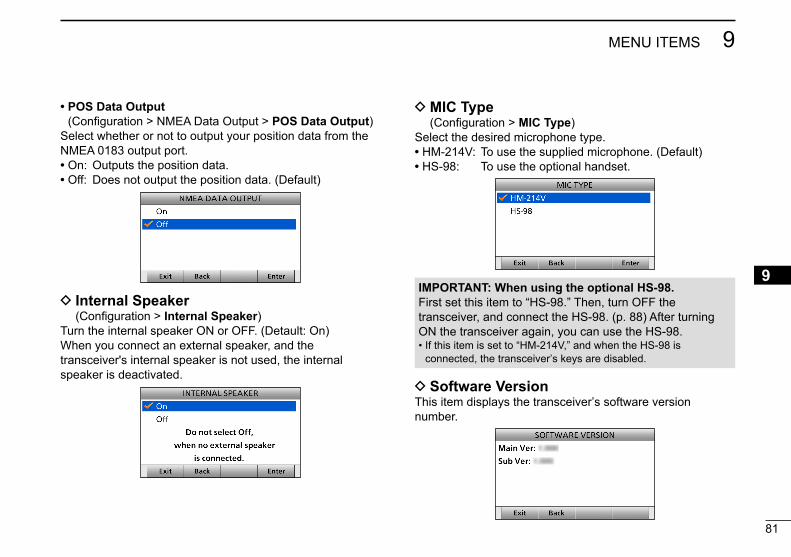
81
9MENU ITEMS
New2001
12345678910111213141516
D MIC Type (Configuration > MIC Type)
Select the desired microphone type.• HM-214V: To use the supplied microphone. (Default)• HS-98: To use the optional handset.
• POS Data Output (Configuration > NMEA Data Output > POS Data Output)
Select whether or not to output your position data from the NMEA 0183 output port.• On: Outputs the position data.• Off: Does not output the position data. (Default)
D Internal Speaker (Configuration > Internal Speaker)
Turn the internal speaker ON or OFF. (Detault: On)When you connect an external speaker, and the transceiver's internal speaker is not used, the internal speaker is deactivated.
D Software VersionThis item displays the transceiverʼs software version number.
IMPORTANT: When using the optional HS-98.First set this item to “HS-98.” Then, turn OFF the transceiver, and connect the HS-98. (p. 88) After turning ON the transceiver again, you can use the HS-98.• If this item is set to “HM-214V,” and when the HS-98 is
connected, the transceiverʼs keys are disabled.

8282
CONNECTIONS AND MAINTENANCE10 Connections
Transceiver’s rear panel view
Remote alarm outputIEC61162-1 IN (+)IEC61162-1 IN (–)
GND
Remote alarm input/CLONEIEC61162-1 OUT (+)IEC61162-1 OUT (–)
q NMEA 0183 CONNECTORS Connects to IEC61162-1 Out lines of a PC or IEC61162-1 sentence format DSC or DSE compatible navigation equipment, to receive position data from other ships.
Connects to IEC61162-1 In lines of a GPS receiver for position data.
• A GPS receiver compatible with IEC61162-1 format RMC, GGA, GNS, or GLL and VTG sentences is required. Ask your dealer about suitable GPS receivers.
t
y e
w
r
q Remote alarm output terminal• 4 V DC*• Maximum 10 mA** When the external equipment is connected between this terminal and the GND terminal.
When DSC call that is related to “Distress” as described below is received, 4 V DC is output and the key backlight blinks.• Distress call• Distress acknowledgement• Distress Relay call• Distress Relay acknowledgement• Distress Cancel call• DSC call whose category is “Distress”
Remote alarm input terminalWhen this terminal shorts to the GND terminal, the transceiver sends the Distress call.This terminal can be used as an external distress switch.

8383
10CONNECTIONS AND MAINTENANCE
12345678910111213141516
CAUTION: Transmitting without an antenna (y) above may damage the transceiver.
r D-SUB 25-PIN Connects to a printer (IBM® centronics or compatible) to
print out the received DSC call contents.
t ANTENNA CONNECTOR (to receive on Channel 70)y ANTENNA CONNECTOR Connects to a marine VHF antenna with a PL-259
connector.
e EXTERNAL SPEAKER/VDR CONNECTOR Connects to a voice recorder or an external speaker. • Lead: Thicker than 0.75 sq mm,
Length: Shorter than 1.5 m is recommended.
CAUTION: After connecting the DC power cable, cover the connector with a tape, as shown below, to prevent water seeping into the connection.
SP (+)SP (–)
NC
NCVDR* (–)VDR* (+)
Transceiver’s rear panel view
*VDR: Voyage Data Recorder
w DC POWER CONNECTOR Connects the PS-310 with the DC power cable of the PS-
310. (p. 86)
Rubber vulcanizing tape
D IEC61162-1 In/Out linesʼ specificationsPIN SPECIFICATIONS
IEC61162-1 OUT (+) Output level: 5 V/40 mA maximum (RS-422 balanced type)IEC61162-1 OUT (–)
IEC61162-1 IN (+) Input level: Less than 2 mA (at 2 V applied)IEC61162-1 IN (–)

84
10 CONNECTIONS AND MAINTENANCE
New2001
AntennaA key element in the performance of any communication system is the antenna. Ask your dealer about antennas and the best place to mount them.
Fuse replacementOne fuse is installed in the supplied DC power cable. If the fuse blows, track down the source of the problem, repair it, and replace the damaged fuse with a new one of the proper rating.Fuse rating: 10 A
CleaningIf the transceiver becomes dusty or dirty, wipe it clean with a soft, dry cloth.
DO NOT use harsh solvents such as Benzine or alcohol, as they will damage transceiver surfaces.
TRANSCEIVER
To the[NMEA 0183]connector
OPC-980
To a USB port
OPC-478UC
PC
D Software maintenanceThe Icom customer support center provides the firmware file for the transceiver’s maintenance. You can update the transceiver’s firmware through a PC.
Connections (Continued)
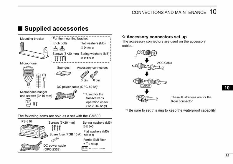
85
10CONNECTIONS AND MAINTENANCE
New2001
12345678910111213141516
D Accessory connectors set upThe accessory connectors are used on the accessory cables.
*2 Be sure to set this ring to keep the waterproof capability.
Solder
ACC Cable
These illustrations are for the 8-pin connector.
Supplied accessories
The following items are sold as a set with the GM600.
Flat washers (M5)
Screws (5×20 mm) Spring washers (M5)
DC power cable(OPC-2352)
PS-310
Spare fuse (FGB 15 A)
Ferrite EMI filter+ Tie wrap
Mounting bracket For the mounting bracketKnob bolts Flat washers (M5)
Screws (5×20 mm) Spring washers (M5)
Microphone
Microphone hanger and screws (3×16 mm)
Sponges Accessory connectors
6 pin 8 pin
DC power cable (OPC-891A)*1
*1 Used for the transceiverʼs operation check. (12 V DC only)
*2
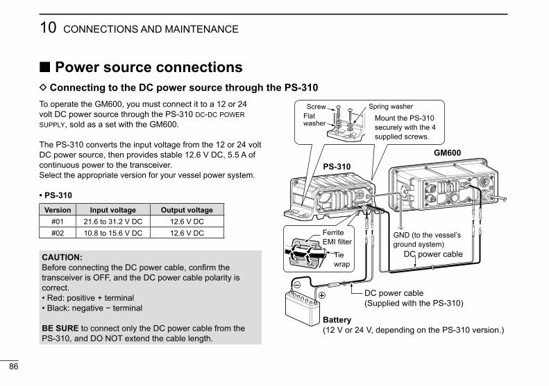
86
10 CONNECTIONS AND MAINTENANCE
New2001
Power source connections D Connecting to the DC power source through the PS-310
CAUTION: Before connecting the DC power cable, confirm the transceiver is OFF, and the DC power cable polarity is correct.• Red: positive + terminal• Black: negative − terminal
BE SURE to connect only the DC power cable from the PS-310, and DO NOT extend the cable length.
To operate the GM600, you must connect it to a 12 or 24 volt DC power source through the PS-310 dc-dc power supply, sold as a set with the GM600.
The PS-310 converts the input voltage from the 12 or 24 volt DC power source, then provides stable 12.6 V DC, 5.5 A of continuous power to the transceiver.Select the appropriate version for your vessel power system.
• PS-310Version Input voltage Output voltage
#01 21.6 to 31.2 V DC 12.6 V DC#02 10.8 to 15.6 V DC 12.6 V DC
PS-310GM600
Battery(12 V or 24 V, depending on the PS-310 version.)
DC power cable( Supplied with the PS-310)
DC power cable
GND (to the vesselʼs ground system)
Screw
Mount the PS-310 securely with the 4 supplied screws.
Spring washerFlat washer
FerriteEMI filter
Tiewrap

87
10CONNECTIONS AND MAINTENANCE
New2001
12345678910111213141516
Mounting the transceiverThe supplied universal mounting bracket with your transceiver enables overhead or flat mounting.
• Mount the transceiver securely with the 4 supplied screws (M5 × 20) to a surface that is more than 10 mm thick and can support more than 5 kg.
• Mount the transceiver so its face is at 90° to your line of sight when operating.
CAUTION: Keep the transceiver and microphone at least 1 meter away from your vessel’s magnetic navigation compass.
NOTE:• Check the installation angle; the function display may not
be easy to read at some angles.• When mounting the transceiver on the place that is prone
to strong vibration, use the supplied sponges between the transceiver and mounting bracket to reduce the effect of the vibration.
Overhead mounting
Flat mounting
Sponges reduce the vibration effects.See NOTE to the left.
*
Sponge*These screws are shown as only a mounting example. Not supplied accessories.
Sponge*

8888
10 CONNECTIONS AND MAINTENANCE
Handset (HS-98)
[MIC CONNECTOR]
Speaker Cradle
weq
D ConnectionInsert the connector into the [MIC CONNECTOR] on the front panel, and tighten the cable nut, as shown below.
q SPEAKER SWITCH When the switch is set to the “ ” position: You can hear the receive audio from the remote controller
speaker.
When the switch is set to the “ ” position: Mutes the remote controller speaker output. • You can hear the receive audio from the handset. Put the handset into the cradle to output the receive
audio from the remote controller speaker.
w HANDSET CONNECTOR Insert the connector into the [MIC CONNECTOR] on the
front panel.
e PTT SWITCH [PTT] Hold down to transmit, release to receive.
IMPORTANT: When using the optional HS-98First set the “MIC Type” item to “HS-98” in the Menu screen. Then, turn OFF the transceiver, and connect the HS-98. After turning ON the transceiver again, you can use the HS-98. (p. 81)

New2001
89
11SPECIFICATIONS AND OPTIONS
12345678910111213141516
SpecificationsThis specification is described when the GM600 is used with the PS-310 dc-dc power supply.All stated specifications are subject to change without notice or obligation.
D General• Frequency coverage: TX 156.025–161.600 MHz RX 156.025–162.000 MHz 156.525 MHz (CH70/DSC)• Mode: FM (16K0G3E), DSC (16K0G2B)• Operating temp. range: –15°C to +55°C• Current drain (at 24 V): TX high (25 W) 3.3 A
Maximum audio 2.0 A• Power supply requirement: 12/24 V DC (negative ground) PS-310 Input voltage: 21.6 to 31.2 V (#01)
10.8 to 15.6 V (#02)• Frequency error: ±0.5 kHz (–15°C to +55°C)• Antenna impedance: 50 ˘ nominal (Unbalanced)• Dimensions (Projections not included): GM600: 263 (W) × 110 (H) × 109.4 (D) mm PS-310: 216 (W) × 79 (H) × 125 (D) mm• Weight (approximately): GM600: 1.6 kg PS-310: 930 g
D Transmitter• Output power: 25 W or 1 W• Modulation system: Variable reactance frequency
modulation• Max. frequency deviation: ±5.0 kHz• Spurious emissions: Less than 0.25 µW• Adjacent channel power: More than 70 dB• Audio harmonic distortion: Less than 10% (at 1 kHz, 60% deviation)• Residual modulation: More than 40 dB• Audio frequency response: +1 to –3 dB of 6 dB/octave range from
300 Hz to 3000 Hz
D Receiver• Receive system: Double conversion superheterodyne• Sensitivity: FM: –7 dBµ emf (typical) (20 dB SINAD) DSC (CH70): –7 dBµ emf (typical) (1% BER)• Squelch sensitivity: Less than –2 dBµ• Intermodulation: More than 75 dB More than 73 dBµ emf (CH70/DSC)• Spurious response: More than 75 dB More than 73 dBµ emf (CH70/DSC)• Adjacent channel selectivity: More than 75 dB More than 73 dBµ emf (CH70/DSC)• Audio output power: More than 10 W at 10% distortion into
an external speaker (4 ˘ load)• Ham and noise: More than 40 dB• Audio frequency response: +1 to –3 dB of –6 dB/octave range
from 300 Hz to 3000 Hz

New2001
90
11 SPECIFICATIONS AND OPTIONS
New2001
Options• PS-310 dc-dc power supply
Provides stable 12.6 V DC output converted from a DC power source.
Version Input voltage Output voltage#01 21.6 to 31.2 V DC 12.6 V DC#02 10.8 to 15.6 V DC 12.6 V DC
• HS-98 handset Provides clear audio reception during offshore conditions and comes in handy for listening privacy on board.
Approved Icom optional equipment is designed for optimal performance when used with an Icom transceiver.Icom is not responsible for the destruction or damage to an Icom transceiver in the event the Icom transceiver is used with equipment that is not manufactured or approved by Icom.
D Dimensions (Unit: mm)
274
114
121.
5
250
148.
25
93.7
5
93.528
165
79
54 125
110
190216
GM600
PS-310

91
12TROUBLESHOOTING
New2001
12345678910111213141516
PROBLEM POSSIBLE CAUSE SOLUTION REF.The transceiver does not turn ON.
• Bad connection to the power supply.
• Fuse blows.
• Check the connection to the transceiver and power supply.
• Repair the problem, and then replace the fuse.
p. 86
p. 84
Little or no sound comes from the speaker.
• Squelch level is set too high.• Volume level is set too low.• The internal speaker is OFF.
• Set the squelch to the threshold point.• Set the volume to a suitable level.• Turn ON the internal speaker.
p. 15p. 15p. 81
You cannot transmit, or cannot select high power.
• Some channels are set for low power or receive only by regulations.
• The output power is set to low.
• Change channels.
• Push [HI/LO] to select high power.
pp. 13 93
p. 15Scan does not start. • More than 2 favorite channels are not set. • Set the desired channels as Favorite
channels.pp. 21,
78No beep sounds. • The Key Beep function is OFF. • Turn ON the Key Beep function. p. 78The Main screen is not displayed at power ON.
• MMSI (DSC self ID) code is not set. • Set the MMSI (DSC self ID) code. p. 9
Individual or Group ID cannot be set.
• The entered ID code is incorrect. First digit must be set to between ʻ1ʼ and ʻ9ʼ for the Individual ID. First digit must be set to ʻ0ʼ for the Group ID.
• Enter a correct ID code. pp. 23, 24
“??” blinks instead of the position and time.
• 4 hours have passed after you manually entered the position.
• The GPS position is invalid.
• Enter the position. p. 25
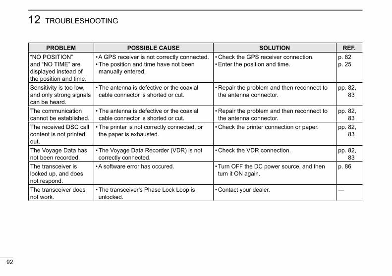
New2001
92
12 TROUBLESHOOTING
New2001
PROBLEM POSSIBLE CAUSE SOLUTION REF.“NO POSITION” and “NO TIME” are displayed instead of the position and time.
• A GPS receiver is not correctly connected.• The position and time have not been manually entered.
• Check the GPS receiver connection.• Enter the position and time.
p. 82p. 25
Sensitivity is too low, and only strong signals can be heard.
• The antenna is defective or the coaxial cable connector is shorted or cut.
• Repair the problem and then reconnect to the antenna connector.
pp. 82, 83
The communication cannot be established.
• The antenna is defective or the coaxial cable connector is shorted or cut.
• Repair the problem and then reconnect to the antenna connector.
pp. 82, 83
The received DSC call content is not printed out.
• The printer is not correctly connected, or the paper is exhausted.
• Check the printer connection or paper. pp. 82, 83
The Voyage Data has not been recorded.
• The Voyage Data Recorder (VDR) is not correctly connected.
• Check the VDR connection. pp. 82, 83
The transceiver is locked up, and does not respond.
• A software error has occured. • Turn OFF the DC power source, and then turn it ON again.
p. 86
The transceiver does not work.
• The transceiver's Phase Lock Loop is unlocked.
• Contact your dealer. —

93
13CHANNEL LIST
New2001
12345678910111213141516
• International channelsCH Frequency (MHz) CH Frequency (MHz) CH Frequency (MHz) CH Frequency (MHz) CH Frequency (MHz)
Transmit Receive Transmit Receive Transmit Receive Transmit Receive Transmit Receive01 156.050 160.650 16 156.800 156.800 62 156.125 160.725 77 156.875 156.875 1019 156.950 156.95002 156.100 160.700 17*1 156.850 156.850 63 156.175 160.775 78 156.925 161.525 1020 157.000 157.00003 156.150 160.750 18 156.900 161.500 64 156.225 160.825 79 156.975 161.575 1078 156.925 156.92504 156.200 160.800 19 156.950 161.550 65 156.275 160.875 80 157.025 161.625 1079 156.975 156.97505 156.250 160.850 20 157.000 161.600 66 156.325 160.925 81 157.075 161.675 2019 161.550 161.55006 156.300 156.300 21 157.050 161.650 67 156.375 156.375 82 157.125 161.725 2020 161.600 161.60007 156.350 160.950 22 157.100 161.700 68 156.425 156.425 83 157.175 161.775 2078 161.525 161.52508 156.400 156.400 23 157.150 161.750 69 156.475 156.475 84 157.225 161.825 2079 161.575 161.57509 156.450 156.450 24 157.200 161.800 70*2 156.525 156.525 85 157.275 161.875 - - - - - - - -10 156.500 156.500 25 157.250 161.850 71 156.575 156.575 86 157.325 161.925 - - - - - - - -11 156.550 156.550 26 157.300 161.900 72 156.625 156.625 87 157.375 157.375 - - - - - - - -12 156.600 156.600 27 157.350 161.950 73 156.675 156.675 88 157.425 157.425 - - - - - - - -13 156.650 156.650 28 157.400 162.000 74 156.725 156.725 - - - - - - - - - - - - - - - -14 156.700 156.700 60 156.025 160.625 75*3 156.775 156.775 - - - - - - - - - - - - - - - -
15*1 156.750 156.750 61 156.075 160.675 76*3 156.825 156.825 - - - - - - - - - - - - - - - -
*1 Channels 15 and 17 may also be used for on-board communications provided the effective radiated power does not exceed 1 W, and subject to the national regulations of the administration concerned when these channels are used in its territorial waters.
*2 DSC operation only.*3 The output power of channels 75 and 76 are limited to
low power (1 W) only. The use of these channels should be restricted to navigation-related communications only, and all precautions should be taken to avoid harmful interference to channel 16, e.g. by means geographical separation.

New2001
94
New2001
DIGITAL INTERFACE (IEC 61162-1)14 I/O Sentences
D Version numberIEC61162-1 Ed.4(2010-11)
D Input sentences (IEC 61162-1)RMC, GGA, GNS, GLL, and VTG
D Input sentence description• RMC—Recommended minimum specific GNSS data$**RMC, hhmmss.ss, A, llll.ll, a, yyyyy.yy, a, x.x, x.x, ddmmyy, x.x, a, a, a*hh<CR><LF> 1 2 3 4 5 6 7 8 9 10 11 12 13
1 UTC of position fix (000000.00 to 235959.99) 8 Course over ground, degrees true (0.0 to 360.0)2 Status (A=data valid, V=navigation receiver warning) 9 Date (010100 to 311249)3 Latitude (0000.0000 to 9000.0000) 10 Magnetic variation, degrees (no use)4 N/S 11 E/W
5 Longitude (00000.0000 to 18000.0000) 12 Mode indicator (A=Autonomous, D=Differential, F=Float RTK, N=No fix, P=Precise, R=Real Time Kinematic, S=Simulator mode)
6 E/W 13 Navigational status indicator (no use)7 Speed over ground, knots (0.0 to 100.0)
• GGA—Global positioning system (GPS) fix data$**GGA, hhmmss.ss, llll.ll, a, yyyyy.yy, a, x, xx, x.x, x.x, M, x.x, M, x.x, xxxx*hh<CR><LF> 1 2 3 4 5 6 7 8 9 10 11 12 13 14
1 UTC of position (000000.00 to 235959.99) 8 Horizontal dilution of precision (no use)2 Latitude (0000.0000 to 9000.0000) 9 Antenna altitude above/below mean sealevel (no use)3 N/S 10 Unit M4 Longitude (00000.0000 to 18000.0000) 11 Geoidal separation (no use)5 E/W 12 Unit M6 GPS quality indicator (1 to 5) 13 Age of differential GPS data (no use)7 Number of satellites in use (no use) 14 Differential reference station ID (no use)

New2001
95
14DIGITAL INTERFACE (IEC 61162-1)
12345678910111213141516
• GNS—GNSS fix data$**GNS, hhmmss.ss, llll.ll, a, yyyyy.yy, a, c--c, xx, x.x, x.x, x.x, x.x, x.x, a*hh<CR><LF> 1 2 3 4 5 6 7 8 9 10 11 12 13
1 UTC of position (000000.00 to 235959.99) 8 HDOP (no use)2 Latitude (0000.0000 to 9000.0000) 9 Antenna altitude, meters (no use)3 N/S 10 Geoidal separation (no use)4 Longitude (00000.0000 to 18000.0000) 11 Age of differential data (no use)5 E/W 12 Differential reference station ID (no use)
6 Mode indicator (N=No fix, A=Autonomous, D=Differential, P=Precise, R=Real Time Kinematic, F=Float RTK, S=Simulator mode) 13 Navigational status indicator (no use)
7 Total number of satellites in use (no use)
• GLL—Geographic position – Latitude/longitude$**GLL, llll.ll, a, yyyyy.yy, a, hhmmss.ss, a, x*hh<CR><LF> 1 2 3 4 5 6 7
1 Latitude (0000.0000 to 9000.0000) 5 UTC of position (000000.00 to 235959.99)2 N/S 6 Status (A=data valid V=data invalid)
3 Longitude (00000.0000 to 18000.0000) 7 Mode indicator (A=Autonomous, D=Differential, N=No fix, S=Simulator mode)
4 E/W
• VTG—Course over ground and ground speed$**VTG, x.x, T, x.x, M, x.x, N, x.x, K, a*hh<CR><LF> 1 2 3 4 5 6 7 8 9
1 Course over ground, degrees true (0.0 to 360.0) 6 Unit N2 Unit T 7 Speed over ground, km/h (no use)3 Course over ground, degrees magnetic (no use) 8 Unit K
4 Unit M 9 Mode indicator (A=Autonomous, D=Differential, E=Estimated, M=Manual input, P=Precise, S=Simulator, N=Data not valid)
5 Speed over ground, knots (0.0 to 100.0)

96
14 DIGITAL INTERFACE (IEC 61162-1)
New2001
D Output sentences (IEC 61162-1)DSC and DSE
D Output intervalDSC, DSE: Irregular output (Output immediately after receiving a DSC call.)
D Output sentence description• DSC—Digital selective calling information$CDDSC, xx, xxxxxxxxxx, xx, xx, xx, x.x, x.x, xxxxxxxxxx, xx, a, a*hh<CR><LF> 1 2 3 4 5 6 7 8 9 10 11
1 Format specifier (2 digits) 7 Time or Telephone Number (Maximum 16 digits)2 Address (10 digits) 8 MMSI of ship in distress (10 digits or NULL)3 Category (2 digits or NULL) 9 Nature of distress (2 digits or NULL)
4 Nature of distress or first telecommand (2 digits or NULL) 10 Acknowledgement (R=Acknowledge request, B=Acknowledgement, S=Neither (end of sequence))
5 Type of communication or second telecommand (2 digits) 11 Expansion indicator (E or NULL)6 Position or Channel/frequency (Maximum 16 digits)
• DSE—Expanded digital selective calling$CDDSE, x, x, a, xxxxxxxxxx, xx, c--c, .........., xx, c--c*hh<CR><LF> 1 2 3 4 5 6 7 8 9
1 Total number of sentences (fixed value) 6 Data set ‘1’ (code field, Enhanced position resolution, Maximum 8 characters), NULL
2 Sentence number (fixed value) 7 Additional data sets*1, NULL3 Query/reply flag (fixed value A=Automatic) 8 Data set ‘n’ (NULL)*1
4 Vessel MMSI (10 digits) 9 Data set ‘n’ (NULL)*1
5 Data set ‘1’ (code field, fixed value 00)
*1 This transceiver outputs only “Data set 1.”
I/O Sentences (Continued)

97
14DIGITAL INTERFACE (IEC 61162-1)
New2001
12345678910111213141516
Schematic diagram D IEC61162-1 In/Out lines
Hardware versionThe transceiverʼs hardware version is described on the serial number label, as shown to the right.
Hardware version is described here.Hardware version
Serial number label
1000
P
0.1
1000
P
0.06
8
0.1
0.01
0.1
1000
P
EZAEG2A50AX
EZAEG2A50AX
10
1K 470
1
10
47K
3.3K
10
KDS4148U
ISL81487IBZ-T1 RO2 RE3 DE4 DI 5GND
6A/Y
7B/Z
8VCC
TC7W14FU1234 5
678
PC357N6J000F
100K
470P
470P
IEC61162-1 INPUT+
IEC61162-1 INPUT-
IEC61162-1 OUTPUT+
IEC61162-1 OUTPUT-
NM1RXD
5V
NM1TXD
3.3V
Software versionYou can confi rm the transceiverʼs software version in the Menu screen.See page 81 for details.
The input circuit is electricaly isolated by the PC357N6J000F.
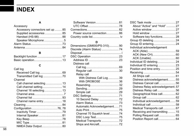
New2001
98
New2001
INDEX
AAccessory
Accessory connectors set up .........85Supplied accessories .....................85Handset (HS-98) ............................ 88Speaker Microphone ........................5
Alarm Status ......................................73Antenna .............................................84
BBacklight function ..............................17Basic operation ..................................13
CCall log
Received Call log ...........................69Transmitted Call log .......................70
ChannelCall channel selecting ....................13Call channel setting ........................14Channel 16 selecting......................13Channel area....................................7Channel list ....................................93Channel name entry ....................... 18
Cleaning ............................................84Configuration ...............................76, 78
Inactivity Timer ...............................79Internal Speaker ............................. 81Key Beep........................................78MIC Type ........................................ 81NMEA Data Output.........................80
Software Version ............................ 81UTC Offset .....................................78
Connections.......................................82Power source connection ...............86
Country code list ................................. iv
DDimensions (GM600/PS-310)............90Discrete (Alarm Status) .....................74Disposal ................................................ iDSC Operation ..................................23
Address ID .....................................23Distress call
Call log ........................................69Regular call .................................30Relay call
With Distress Call Log .............39With DROBOSE ......................36
Resending...................................32Sending.......................................29Simple call ..................................29
DSC Settings..................................7110 Second Delay ........................72Alarm Status ...............................73Automatic Acknowledgement......71Auto Print ....................................75Channel 70 Squelch level ...........74DSC Loop Test ............................75Medical Transports .....................72Ships and Aircraft........................72
DSC Task mode .............................27About “Active” and “Hold” ...........27Active window .............................27Hold window ...............................27Software key functions................28
Group ID deleting ...........................24Group ID entering...........................24Individual acknowledgement
ACK (Able) ..................................59ACK (New CH) ............................60ACK (Unable)..............................60
Individual ID deleting ......................24Individual ID entering .....................23Position and time entry...................25Receiving .......................................54
All Ships call ...............................61Distress acknowledgement .........55Distress Cancel call ....................56Distress Relay acknowledgement .57Distress Relay call ......................56Geographical Area call................62Group call ...................................62Individual acknowledgement.......59Individual call ..............................58Medical Transports call ...............67Receiving and transmitting .........15Polling Request call ....................65Position Report call .....................64

New2001
99
INDEX
New2001
12345678910111213141516
DSC Operation (Continued)Position Request acknowledgement .......................64Position Request Call .................63Ships and Aircraft call .................68Test acknowledgement ...............66Test call .......................................66
SendingDistress call ................................30
Distress acknowledgement .....34Distress Cancel call .................33Distress Relay acknowledgement ...................41Distress Relay call ...................36
Non-Distress call.........................42Group call ................................46Medical Transports call............52All Ships call ............................45Individual acknowledgement ...44Individual call ...........................42Polling Request acknowledgement ...................49Position Request acknowledgement ...................48Position Request call ...............47Ships and Aircraft call ..............53Test call ...................................50Test call acknowledgement .....51
Dualwatch/Tri-watch ..........................22Dualwatch ......................................22Tri-watch ........................................22
EEmergency .......................................... ii
Using channel 16 ............................. iiUsing digital selective calling (Ch 70) . ii
Explicit definitions ................................. i
FFavorite channels ..............................21
Clearing ..........................................21Selecting ........................................21Setting ............................................21
Front panel ..........................................2Function display (Main screen)............6
Channel area....................................7Information area ...............................7Position and Time area .................... 8Status area .......................................6Software key area ............................6Task area..........................................6
Fuse replacement ..............................84
GGroup ID deleting ..............................24Group ID entering ..............................24
HHandset (HS-98)................................ 88
Connection ..................................... 88
IIcon description .................................. ivIn/Out linesʼ specifications (IEC61162-1) .....................................83Inactivity Timer
Distress Related .............................79DSC Related ..................................79Not DSC Related............................79RT Related .....................................80
Individual callAcknowledgement ..........................59Receiving .......................................58Sending ..........................................42
Individual ID deleting .........................24Individual ID entering .........................23Information area ..................................7Installation
Installation note ................................ iiMounting the transceiver ................87
LLicense (Operator)............................... 1License (Ship station) .......................... 1

100
INDEX
New2001 New2001
MMaintenance ......................................84
Antenna ..........................................84Cleaning .........................................84Fuse replacement ..........................84Software maintenance ...................84
Menu ...............................................76All Ships call ...................................45Compose Distress ..........................30Compose DROBOSE .....................36Compose Non-Distress
Individual call ..............................42Group call ...................................46Position Request call ..................47Test call .......................................50Medical Transports call ...............52Ships and Aircraft call .................53
Configuration ............................76, 78Inactivity Timer ............................79Internal Speaker ......................... 81Key Beep ....................................78MIC Type .................................... 81NMEA Data Output .....................80Software Version......................... 81UTC Offset ..................................78
Construction ...................................10DSC Log.........................................69DSC Settings..................................71Menu item selecting .......................12Menu screen ..................................10
Radio Settings ................................76Call Channel ...............................77Dual/Tri-Watch ............................77FAV on MIC .................................78FAV Settings ...............................78Scan Timer..................................77Scan Type ...................................77
Microphone Lock function..................17MMSI code entry ................................. 9Mounting the transceiver ...................87
NNMEA Data Output
DSC Data Output ...........................80POS Data Output ........................... 81
Normal scan ......................................20
OOperating rules .................................... 1Options ..................................................
90Other messages ................................69
PPanel description .................................2Position and Time area ........................ 8Position area........................................ 8Position and time entry ......................25Power source connections ................86Precautions..........................................iiiPreparation (MMSI code entry) ........... 9Priority scan .......................................20PS-310...................................................
86Power source connection ...............86Dimensions ....................................90
RRadio Settings ...................................77Radio Telephone (RT) mode .............14Received Call log...............................69
Distress message...........................69Other messages .............................69
Receiving ...........................................15Routine (Alarm Status) ......................73
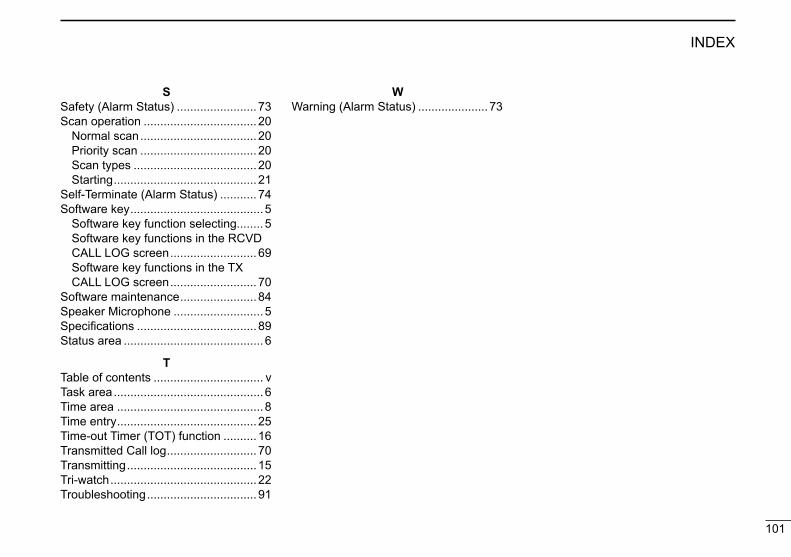
101
INDEX
New2001
12345678910111213141516
New2001
SSafety (Alarm Status) ........................73Scan operation ..................................20
Normal scan ...................................20Priority scan ...................................20Scan types .....................................20Starting ...........................................21
Self-Terminate (Alarm Status) ...........74Software key ........................................5
Software key function selecting........5Software key functions in the RCVD CALL LOG screen ..........................69Software key functions in the TX CALL LOG screen ..........................70
Software maintenance .......................84Speaker Microphone ...........................5Specifications .................................... 89Status area ..........................................6
TTable of contents ................................. vTask area .............................................6Time area ............................................ 8Time entry ..........................................25Time-out Timer (TOT) function ..........16Transmitted Call log ...........................70Transmitting .......................................15Tri-watch ............................................22Troubleshooting ................................. 91
WWarning (Alarm Status) .....................73
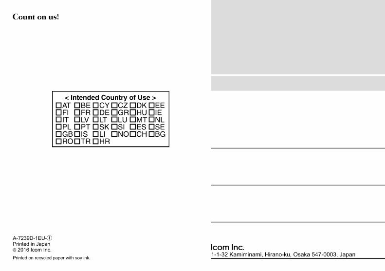
1-1-32 Kamiminami, Hirano-ku, Osaka 547-0003, Japan
A-7239D-1EU-qPrinted in Japan© 2016 Icom Inc.Printed on recycled paper with soy ink.
< Intended Country of Use >ATFIITPLGBRO
BEFRLVPTISTR
CYDELTSKLIHR
CZGRLUSINO
DKHUMTESCH
EEIENLSEBG