vhdl implementation of multiplier less high performance dwt filter bank wce2007
TRANSCRIPT

Abstract—The JPEG 2000 image coding standard employs the
biorthogonal 9/7 wavelet for lossy compression. The performance
of hardware implementation of 9/7-filter bank depends on
accuracy and efficiency. A method for processing signal in a
canonical signed digit format, filter due to fractional coefficient
includes the steps of obtaining real coefficients optimized to
desired filter characteristics, calculating scaling factors for each
real coefficients which minimizes errors between the real
coefficients and converted canonical signed digit codes, producing
optimum canonical signed digit coefficients by using the calculated
scaling factors and filtering input data by using the optimum
canonical signed digit form coefficient. For multiplierless
operation canonical sign digit plays an important roll in processing
signal. Advantage of this implementation is to reduce the number
of adders in hardware and also increase the speed of operation.
Filter bank filters the low resolution information using lowpass
filter and high resolution information by using high pass filter.
Wavelet co-efficient decides the characteristic of filter. In this
method we used 9/7 wavelet transform to implement multiplierless
operation.
To implement multiplierless Hardware we used sum or
difference of power two-representation i.e. canonical signed digit
form. The canonical signed digit form is optimal in terms of how
many nonzero digits are required to represent a given number. On
an average, a canonical representation used two thirds as many
nonzero digits as a binary representation, so the canonical signed
digit form can significantly reduce the number of adders required
in hardware.
Keywords - Biorthogonal 9/7, canonical sign digit, multiplierless
I. INTRODUCTION
Many image and video compression techniques are based on
the discrete wavelet transform (DWT). A great number of
analysis/synthesis filters for the DWT have been proposed past.
However Antonini’s 9/7 filter [1] is most popular one, since it
combines good performance and rational filter length. It is
stressed have that 9/7 filter is default filter of the upcoming
JPEG 2000.[2] standard and included in MPEG4 [3] standard.
Manuscript received December 15, 2006. This work was supported in part
by the circular No. ASS/2005-06/251 dt 14/02/06
Mr. M.M Aswale1 is with the Deptt. of Electronics and Communication
Engineering, G.H. Raisoni College of Engineering,Nagpur-16, INDIA.
(e-mail: mohan_ghrp@ yahoo.com).
Ms.R. B. Patil2, is with the Deptt. of Electronics and Communication
Engineering,G.H.Raisoni College of Engineering,Nagpur-16, INDIA.
(email: [email protected]).
A digital filter is most important and most frequently used
element in processing a digital signal and includes delays,
multipliers and adders. The simplest form of digital filter is
multiplier with number of delays. This type of filter is generally
used for processing a signal such as controlling gains. The
digital filter is generally comprised of a plurality of multipliers,
which occupy large areas and consume much power, impose
constraints on a one-chip solution when circuits are integrated.
In this aspect, efforts have been expanded to reduce the
associated hardware complexity by simplifying multipliers used
in such digital filters. To avoid multipliers we give preference to
canonical signed digit form in FIR filter structure. The present
invention relates to method for processing image in a filter
employing canonic signed digit (CSD) code and circuit suitable
for the method, which can improve performance of the filter and
can be adapted to many kinds of filters by increasing resolution
of scaling factors [3]. A fast, efficient, multiplierless
high-performance implementation of biorthogonal 9/7 discrete
wavelet transform (DWT) on a field programmable gate array
(FPGA) is described. The structure of one stage of two-channel
biorthogonal filter bank used to compute the DWT is shown in
fig1. In a biorthogonal filter bank all the filters are finite impulse
response (FIR) and symmetric. The synthesis section of a filter
bank inverts the analysis section, assuming PR, the
reconstructed image will equal original image. This occurs
when the following PR conditions met [3].
Fig.1. Two-channel biorthogonal wavelet filter bank.
F(z)H(z)+J(z)G(z)=2z-1
(1)
F(z)H(-z)+J(z)G(-z)=0
(2)
The performance of a hardware implementation of filter bank
depends on how well the two PR conditions and linear phase are
preserved. The no aliasing condition of equation (2) is satisfied
by design in the usual way
g(n) = (-1)n
f(n) G(z) = F( -z)
j(n) = -(-1)n
h(n) J(z) = -H(-z) (3)
VHDL Implementation of Multiplierless, High
Performance DWT Filter Bank
Mr. M.M. Aswale1
, Prof. Ms. R.B Patil2 ,Member ISTE
Proceedings of the World Congress on Engineering 2007 Vol IWCE 2007, July 2 - 4, 2007, London, U.K.
ISBN:978-988-98671-5-7 WCE 2007

These relationship reduces the problem from the design of four
filters to the design of just two, once the two lowpass filters
(LPF’s) are designed, the high pass filters (HPF’s) are derived
from equations (3).[4]. In this paper aspect related to filter
coefficient quantization and hardware architecture of filtering
unit exhaustively explored. Paper is divided into four sections.
Section II focus on lifting scheme approach, Section III
Convolution filter approach and Section IV result and
comparison. For each case the effect of filter coefficient
quantization in performance in terms of peak signal to noise
ratio (PSNR) is presented. Experimental results concerning the
PSNR have been acquired by running row- column
implementation of filter under test. The filter alternatives are
mapped on an FPGA using a prototyping platform hosting on
Altera.
II. THE LIFTING SCHEME APPROACH
The lifting scheme based DWT has been included in the
upcoming JPEG 2000 standard because it reduces the arithmetic
complexity [5]. The lifting based DWT implementation of
filtering as described [2] is given bellow. Applying the
following steps to the entire input performs the transformation.
The input is extended before and after the first and last
coefficient.
Forward transformation
Y2n+1 =X2n+1+α *( X2n + X2n+2)
Y2n =X2n+β *( Y2n-1 + Y2n+1)
Y2n+1 =Y2n+1+γ *( Y2n + Y2n+2)
Y2n =Y2n+δ *( Y2n-1 + Y2n+1)
Y2n+1 =Y2n+1* -K
Y2n =Y2n/K
Inverse Transformation
x2n =Y2n * K
x2n+1 = -Y2n+1/ K
x2n =X2n- δ *( X2n-1 + X2n+1)
X2n+1 =X2n+1 -γ *( X2n + X2n+2)
X2n =X2n -β *( X2n-1 + X2n+1)
X2n+1 =X2n+1-α *( X2n + X2n+2)
Where the values of the constants are
α= -1.586134342
β= -0.052980118
γ= 0.882911075
δ=0.413506852
Fig.2. Basic processing block of lifting scheme
A. Quantization of Constant
The 9/7 filter is originally based on a floating point data
representation. Since the scope here is hardware
implementation of 9/7 filter. We focus of equivalent filter that
uses fixed point (FXP) data representation. This is due to the
feel that floating-point data path operators are more complex,
occupy more area and are slower than their fixed point
counterparts. The aim of this subsection is to define the effect of
quantization of the fixed point representation of samples and
filter constants on image quality in terms of PSNR, and filter
implementation in terms of speed and area. The following
results for the PSNR achieved by different quantization of the
constant are obtained using two test images: Lena (512 x 512 x
8) and bridge (512 x 512 x8). The forward filter is a hardware
implementation using the constants above. For the inverse
filtering two types of filter are used. A software double
precision filter with no quantization error and a hardware
implementation using quantized constant.
TABLE I
PSNR measurement
Levels Inverse type Image
1 2 3 4 5 6
Lena ∞ ∞ ∞ ∞ ∞ 80db Software
(double preci) Bridge ∞ ∞ ∞ 65d
b 58db 50db
Lena ∞ ∞ ∞ ∞ 73 db 56 db Hardware
implementation Bridge ∞ ∞ ∞ ∞ 71 db 53 db
B. Architecture for lifting scheme processing
1) Optimized using shift-add operation
Using shift-add operations to replace the multiplications with
constant optimizes the multiplier implementation. An improved
processing block can be obtained that way but a separate block
is needed to perform the multiplication with each constant. The
architecture of the optimized processing unit is shown is fig.3
Proceedings of the World Congress on Engineering 2007 Vol IWCE 2007, July 2 - 4, 2007, London, U.K.
ISBN:978-988-98671-5-7 WCE 2007

Fig.3. Basic processing block
a) Positive constant
b) Negative constant
Two different architectures are given depending on the
constants sign. The multiplication with constant is translated in
summing shifted version of input. When the positive constant is
in fixed point format a term corresponding to each bit with
value for example, multiplication with constant 2.25 which is
represent in fixed point format as 0010.0100 equivalent in
adding two terms The first term is input shifted arithmetically
right two position.
III. CONVOLUTIONAL FILTERS
A. Filter structure and CSD form
In convolutional filter approach FIR structure is implemented
with canonical signed digit form for multiplication operation as
said above.
TABLE II
Quantized filter coefficient for direct implementation
For canonical signed digit form operation, quantized values
need to be expressed as sum or difference of power two, for a
multiplierless implementation. The total number of sum or
difference of power two terms used must be kept to a minimum
in order to achieve hardware efficiency and speed. The
challenge is how to allocate a given SPT terms across the
co-efficient such that compression performance is maximized.
There is a subset of SPT representation called canonical
signed digit (CSD) form; no two adjacent bits are nonzero in
CSD form. The canonical form is optimal in terms of how many
nonzero digits are required to represent a given number. On an
average, a canonical representation uses two third as many
nonzero digits as binary representation, so the canonical signed
digit form can significantly reduces the no of adders required in
hardware.
B. Hardware performance
In relating a hardware implementation of direct form filter,
consideration must be given to the hardware architecture.Fig.4
shows the architectural variation considered here.
Fig.4 Direct form multiplierless FIR structure used for low pass & high pass
filter.
A chain of registers is used to shift the data in and the data is
shifted in accordance with filter coefficient before being
summed. For example, if one of the filter coefficient were
0.46875 = 2-2
– 2-5
the corresponding data word would go to two
shifters and be shifted two and five places respectively before
being summed.
TABLE III
HARDWARE ARCHITECTURE SPECIFICATION.
Specification RCA TREE
H9 (z) F7 (z)
SPT terms 21 11
Size (logic cell) 574 307
Latency 5 4
Input format (8,0) (8,0)
Output format (18, -9) (14, -5)
Clock rate 68.88MHz 102.72 MHz
Power 432.48 mW 347.37 mW
C. Tree operation
(a) Analysis section two level decomposition
Proceedings of the World Congress on Engineering 2007 Vol IWCE 2007, July 2 - 4, 2007, London, U.K.
ISBN:978-988-98671-5-7 WCE 2007
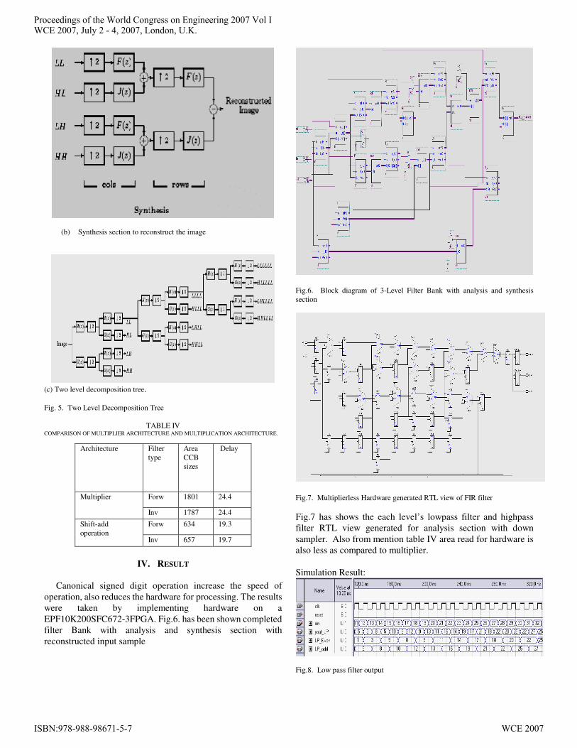
(b) Synthesis section to reconstruct the image
(c) Two level decomposition tree.
Fig. 5. Two Level Decomposition Tree
TABLE IV COMPARISON OF MULTIPLIER ARCHITECTURE AND MULTIPLICATION ARCHITECTURE.
Architecture Filter
type
Area
CCB
sizes
Delay
Forw 1801 24.4 Multiplier
Inv 1787 24.4
Forw 634 19.3 Shift-add
operation Inv 657 19.7
IV. RESULT
Canonical signed digit operation increase the speed of
operation, also reduces the hardware for processing. The results
were taken by implementing hardware on a
EPF10K200SFC672-3FPGA. Fig.6. has been shown completed
filter Bank with analysis and synthesis section with
reconstructed input sample
Fig.6. Block diagram of 3-Level Filter Bank with analysis and synthesis
section
Fig.7. Multiplierless Hardware generated RTL view of FIR filter
Fig.7 has shows the each level’s lowpass filter and highpass
filter RTL view generated for analysis section with down
sampler. Also from mention table IV area read for hardware is
also less as compared to multiplier.
Simulation Result:
Fig.8. Low pass filter output
Proceedings of the World Congress on Engineering 2007 Vol IWCE 2007, July 2 - 4, 2007, London, U.K.
ISBN:978-988-98671-5-7 WCE 2007
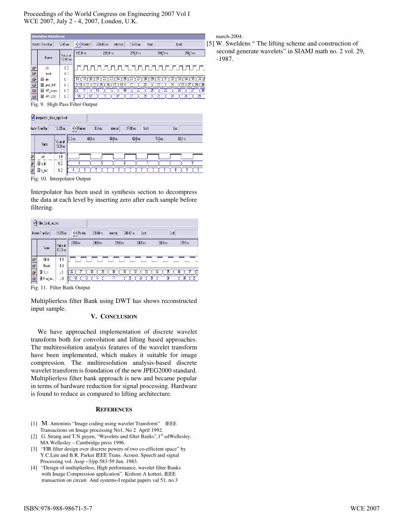
Fig. 9. High Pass Filter Output
Fig. 10. Interpolator Output
Interpolator has been used in synthesis section to decompress
the data at each level by inserting zero after each sample before
filtering.
Fig. 11. Filter Bank Output
Multiplierless filter Bank using DWT has shows reconstructed
input sample.
V. CONCLUSION
We have approached implementation of discrete wavelet
transform both for convolution and lifting based approaches.
The multiresolution analysis features of the wavelet transform
have been implemented, which makes it suitable for image
compression. The multiresolution analysis-based discrete
wavelet transform is foundation of the new JPEG2000 standard.
Multiplierless filter bank approach is new and became popular
in terms of hardware reduction for signal processing. Hardware
is found to reduce as compared to lifting architecture.
REFERENCES
[1] M. Antoninis “Image coding using wavelet Transform” IEEE
Transactions on Image processing No1, No 2 April 1992.
[2] G. Strang and T.N guyen, “Wavelets and filter Banks”,1st edWellesley.
MA Wellesley – Cambridge press 1996.
[3] “FIR filter design over discrete powers of two co-efficient space” by
Y.C.Lim and B.R. Parker IEEE Trans. Acoust. Speech and signal
Processing vol. Assp –3/pp 583-59 Jun. 1983.
[4] “Design of multiplierless, High performance, wavelet filter Banks
with Image Compression application”. Kishore A kotteri, IEEE
transaction on circuit And systems-I regular papers val 51, no.3
march-2004.
[5] W. Sweldens “ The lifting scheme and construction of
second generate wavelets” in SIAMJ math no. 2 vol. 29,
-1987.
Proceedings of the World Congress on Engineering 2007 Vol IWCE 2007, July 2 - 4, 2007, London, U.K.
ISBN:978-988-98671-5-7 WCE 2007