vhdl 3 – sequential logic circuits - auburn universitynelsovp/courses/elec4200/slides/vhdl...
TRANSCRIPT

VHDL 3 – Sequential Logic Circuits
Reference: Roth/John Text: Chapter 2

VHDL “Process” Construct Allows conventional programming language structures to
describe circuit behavior – especially sequential behavior Process statements are executed in sequence Process statements are executed once at start of simulation Process is suspended at “end process” until an event occurs on a
signal in the “sensitivity list”
[label:] process (sensitivity list)declarations
beginsequential statements
end process;
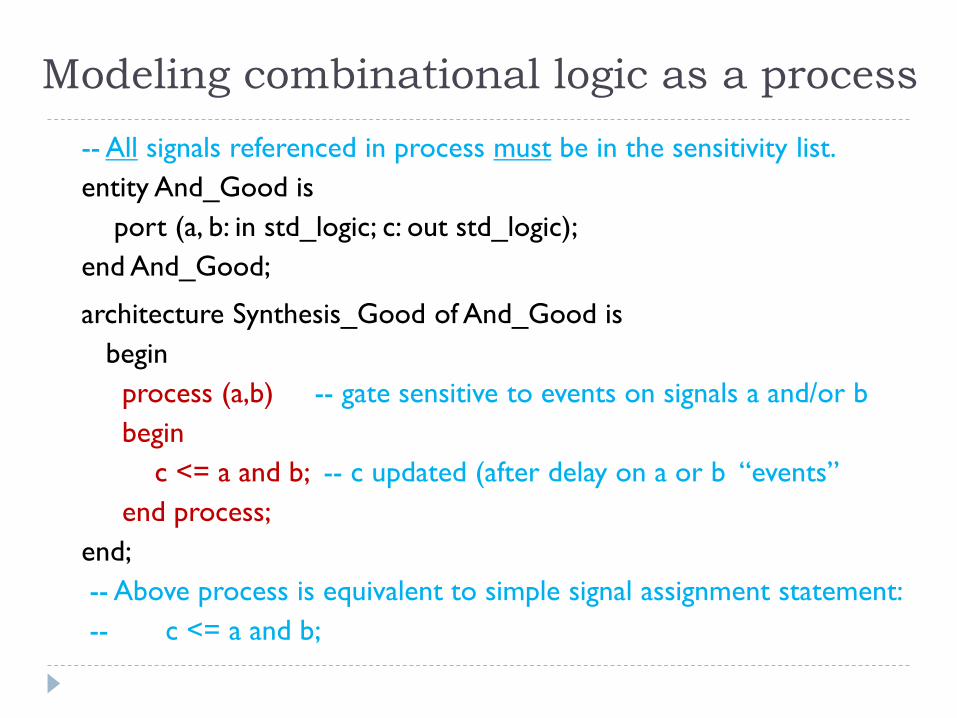
Modeling combinational logic as a process-- All signals referenced in process must be in the sensitivity list.entity And_Good is
port (a, b: in std_logic; c: out std_logic); end And_Good;
architecture Synthesis_Good of And_Good isbegin
process (a,b) -- gate sensitive to events on signals a and/or bbegin
c <= a and b; -- c updated (after delay on a or b “events” end process;
end; -- Above process is equivalent to simple signal assignment statement:-- c <= a and b;

Bad example of combinational logic-- This example produces unexpected results.entity And_Bad is
port (a, b: in std_logic; c: out std_logic); end And_Bad;architecture Synthesis_Bad of And_Bad is
beginprocess (a) -- sensitivity list should be (a, b)begin
c <= a and b; -- will not react to changes in bend process;
end Synthesis_Bad; -- synthesis may generate a flip flop, triggered by signal a

Modeling sequential behavior-- Edge-triggered flip flop/registerentity DFF is port (D,CLK: in bit;
Q: out bit);end DFF;architecture behave of DFF isbegin
process(clk) -- “process sensitivity list”begin
if (clk’event and clk=‘1’) then -- rising edge of clkQ <= D; -- optional “after x” for delayQB <= not D;
end if;end process;
end;
clk’event is an “attribute” of signal clk (signals have several attributes) clk’event = TRUE if an event has occurred on clk at the current simulation time
FALSE if no event on clk at the current simulation time clk‘stable is a complementary attribute (TRUE of no event at this time)
D Q
CLK QB
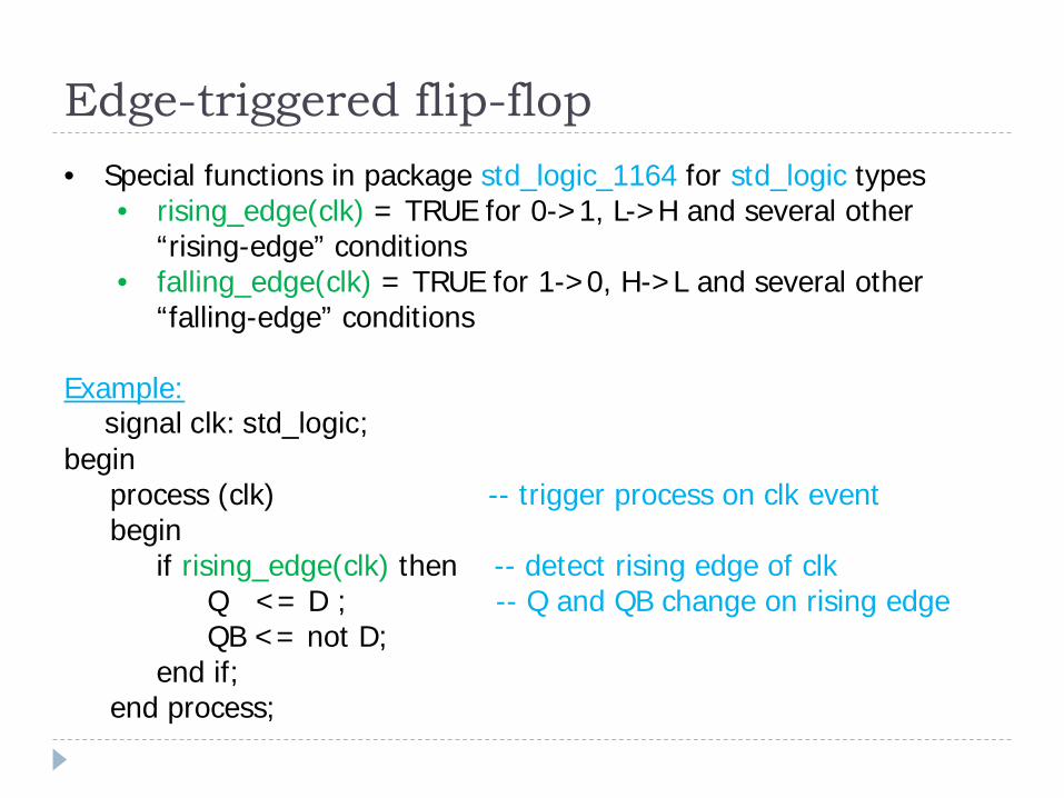
Edge-triggered flip-flop• Special functions in package std_logic_1164 for std_logic types
• rising_edge(clk) = TRUE for 0->1, L->H and several other “rising-edge” conditions
• falling_edge(clk) = TRUE for 1->0, H->L and several other “falling-edge” conditions
Example:signal clk: std_logic;
begin process (clk) -- trigger process on clk eventbegin
if rising_edge(clk) then -- detect rising edge of clkQ <= D ; -- Q and QB change on rising edgeQB <= not D;
end if;end process;
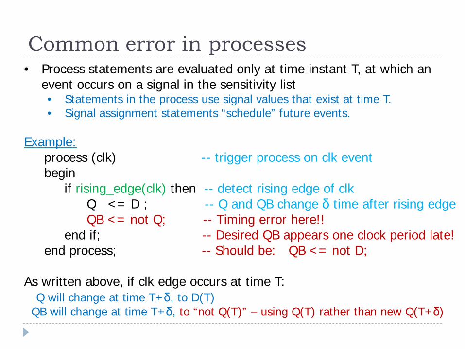
Common error in processes• Process statements are evaluated only at time instant T, at which an
event occurs on a signal in the sensitivity list• Statements in the process use signal values that exist at time T.• Signal assignment statements “schedule” future events.
Example:process (clk) -- trigger process on clk eventbegin
if rising_edge(clk) then -- detect rising edge of clkQ <= D ; -- Q and QB change δ time after rising edgeQB <= not Q; -- Timing error here!!
end if; -- Desired QB appears one clock period late!end process; -- Should be: QB <= not D;
As written above, if clk edge occurs at time T:Q will change at time T+δ, to D(T)
QB will change at time T+δ, to “not Q(T)” – using Q(T) rather than new Q(T+δ)
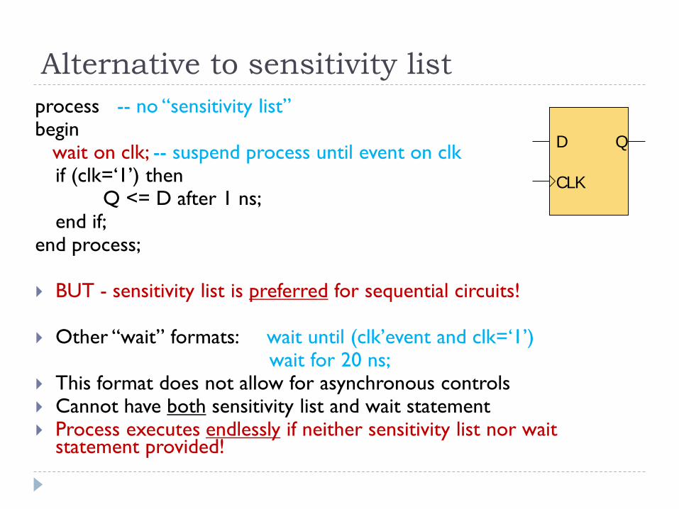
Alternative to sensitivity listprocess -- no “sensitivity list”begin
wait on clk; -- suspend process until event on clkif (clk=‘1’) then
Q <= D after 1 ns;end if;
end process;
BUT - sensitivity list is preferred for sequential circuits!
Other “wait” formats: wait until (clk’event and clk=‘1’)wait for 20 ns;
This format does not allow for asynchronous controls Cannot have both sensitivity list and wait statement Process executes endlessly if neither sensitivity list nor wait
statement provided!
D Q
CLK
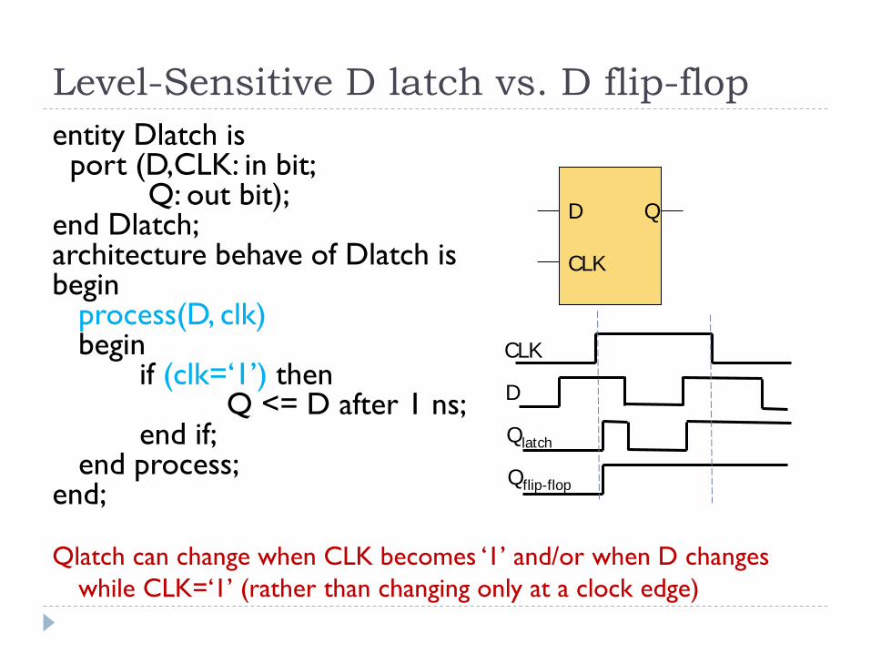
Level-Sensitive D latch vs. D flip-flopentity Dlatch is
port (D,CLK: in bit;Q: out bit);
end Dlatch;architecture behave of Dlatch isbegin
process(D, clk)begin
if (clk=‘1’) thenQ <= D after 1 ns;
end if;end process;
end;
Qlatch can change when CLK becomes ‘1’ and/or when D changes while CLK=‘1’ (rather than changing only at a clock edge)
D Q
CLK
CLK
D
Qlatch
Qflip-flop
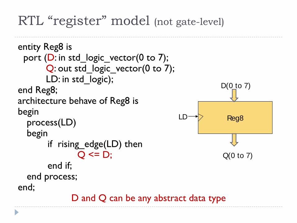
RTL “register” model (not gate-level)
entity Reg8 is port (D: in std_logic_vector(0 to 7);
Q: out std_logic_vector(0 to 7);LD: in std_logic);
end Reg8;architecture behave of Reg8 isbegin
process(LD) begin
if rising_edge(LD) thenQ <= D;
end if;end process;
end;D and Q can be any abstract data type
Reg8
D(0 to 7)
Q(0 to 7)
LD
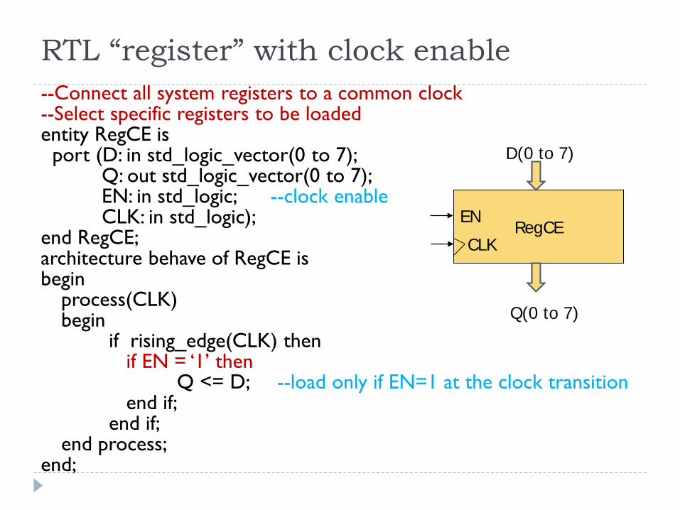
RTL “register” with clock enable--Connect all system registers to a common clock--Select specific registers to be loadedentity RegCE is
port (D: in std_logic_vector(0 to 7);Q: out std_logic_vector(0 to 7);EN: in std_logic; --clock enableCLK: in std_logic);
end RegCE;architecture behave of RegCE isbegin
process(CLK) begin
if rising_edge(CLK) thenif EN = ‘1’ then
Q <= D; --load only if EN=1 at the clock transitionend if;
end if;end process;
end;
RegCE
D(0 to 7)
Q(0 to 7)
CLKEN
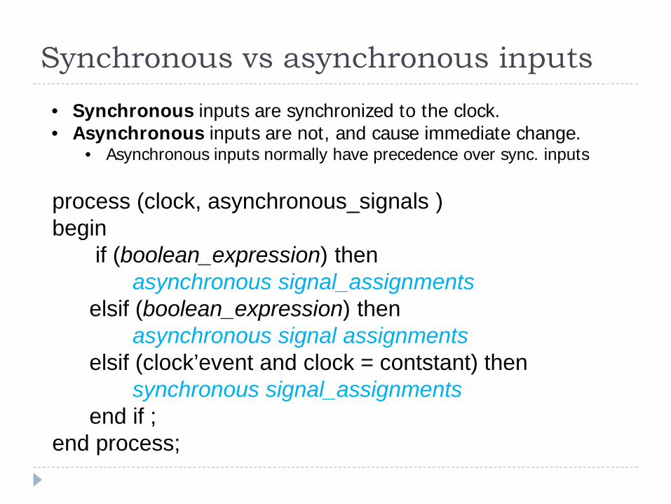
Synchronous vs asynchronous inputs
process (clock, asynchronous_signals )begin
if (boolean_expression) thenasynchronous signal_assignments
elsif (boolean_expression) thenasynchronous signal assignments
elsif (clock’event and clock = contstant) thensynchronous signal_assignments
end if ;end process;
• Synchronous inputs are synchronized to the clock.• Asynchronous inputs are not, and cause immediate change.
• Asynchronous inputs normally have precedence over sync. inputs

Synchronous vs. Asynchronous Flip-Flop Inputsentity DFF is port (D,CLK: in std_logic; --D is a sync input
PRE,CLR: in std_logic; --PRE/CLR are async inputsQ: out std_logic);
end DFF;architecture behave of DFF isbegin
process(clk,PRE,CLR)begin
if (CLR=‘0’) then -- async CLR has precedenceQ <= ‘0’;
elsif (PRE=‘0’) then -- then async PRE has precedenceQ <= ‘1’;
elsif rising_edge(clk) then -- sync operation only if CLR=PRE=‘1’Q <= D;
end if;end process;
end;
CLRD Q
CLKPRE
What happens if CLR = PRE = 0 ??
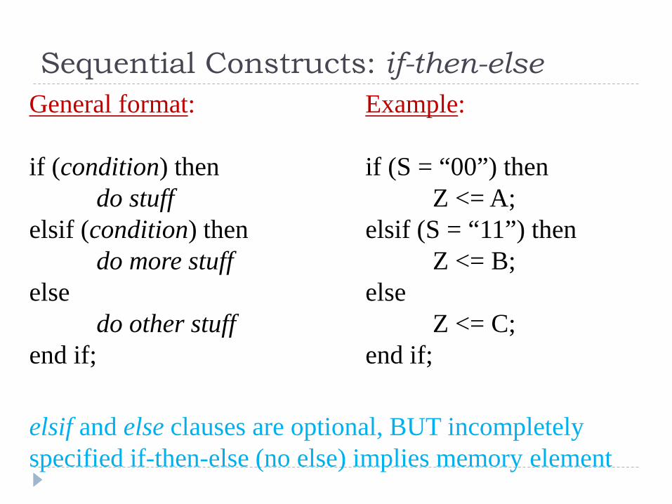
Sequential Constructs: if-then-elseGeneral format: Example:
if (condition) then if (S = “00”) thendo stuff Z <= A;
elsif (condition) then elsif (S = “11”) thendo more stuff Z <= B;
else elsedo other stuff Z <= C;
end if; end if;
elsif and else clauses are optional, BUT incompletely specified if-then-else (no else) implies memory element
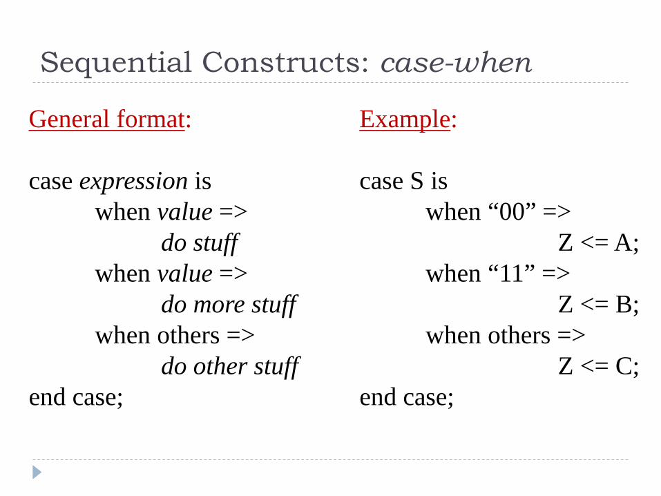
Sequential Constructs: case-when
General format: Example:
case expression is case S iswhen value => when “00” =>
do stuff Z <= A;when value => when “11” =>
do more stuff Z <= B;when others => when others =>
do other stuff Z <= C;end case; end case;
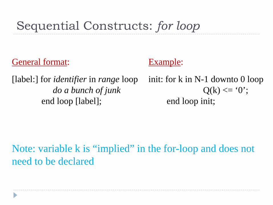
Sequential Constructs: for loop
General format: Example:
[label:] for identifier in range loop init: for k in N-1 downto 0 loopdo a bunch of junk Q(k) <= ‘0’;
end loop [label]; end loop init;
Note: variable k is “implied” in the for-loop and does not need to be declared
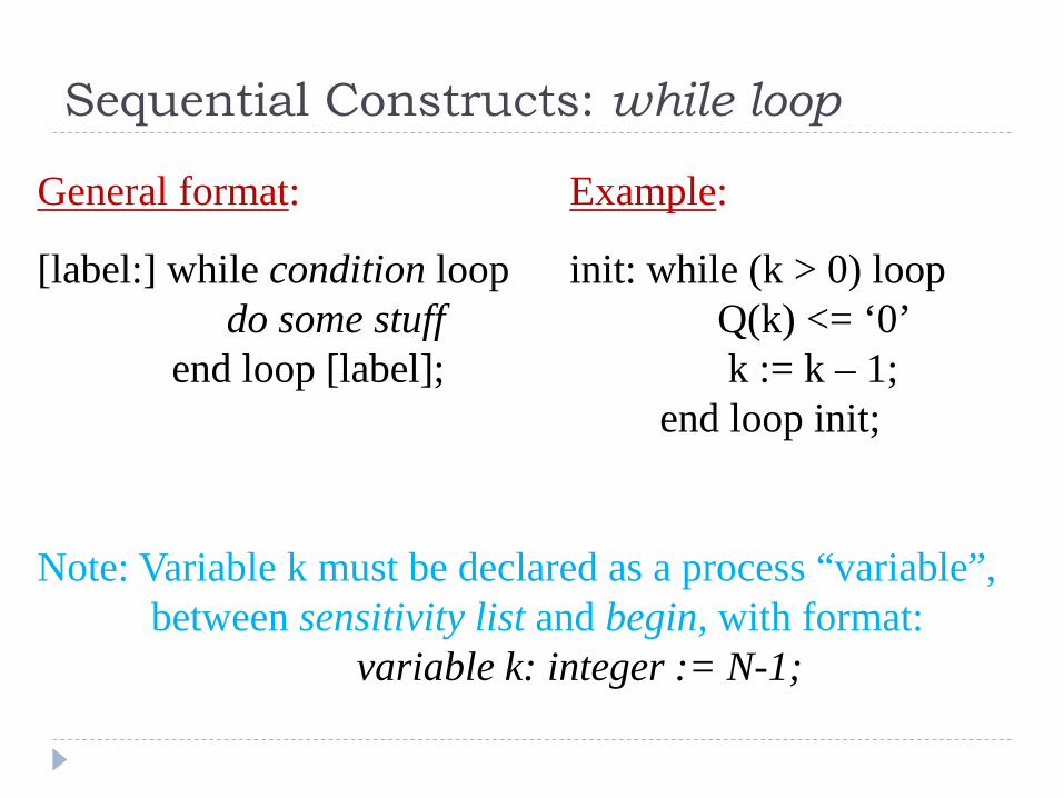
Sequential Constructs: while loop
General format: Example:
[label:] while condition loop init: while (k > 0) loopdo some stuff Q(k) <= ‘0’
end loop [label]; k := k – 1;end loop init;
Note: Variable k must be declared as a process “variable”,between sensitivity list and begin, with format:
variable k: integer := N-1;
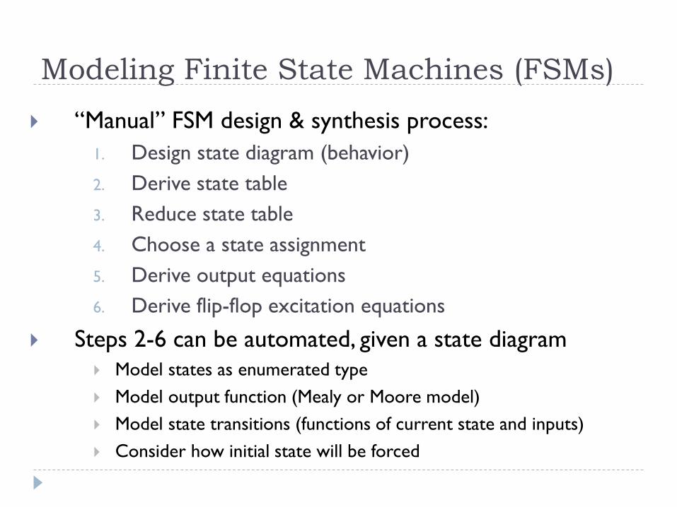
Modeling Finite State Machines (FSMs) “Manual” FSM design & synthesis process:
1. Design state diagram (behavior)2. Derive state table3. Reduce state table4. Choose a state assignment5. Derive output equations6. Derive flip-flop excitation equations
Steps 2-6 can be automated, given a state diagram Model states as enumerated type Model output function (Mealy or Moore model) Model state transitions (functions of current state and inputs) Consider how initial state will be forced

FSM structure
Comb.Logic
FFs
Inputsx
Outputsz
Next StateY
Present Statey
Mealy Outputs z = f(x,y), Moore Outputs z = f(y)
Next State Y = f(x,y)
Clock
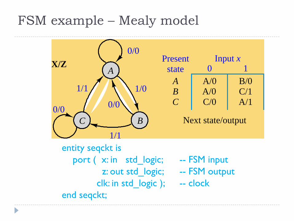
FSM example – Mealy model
B/0 C/1 A/1
0/0
1/1 1/0
1/1
0/0
0/0X/Z Present
stateInput x
0 1
Next state/output
A/0 A/0 C/0
A B C
A
BC
entity seqckt isport ( x: in std_logic; -- FSM input
z: out std_logic; -- FSM outputclk: in std_logic ); -- clock
end seqckt;

FSM example - behavioral model
architecture behave of seqckt istype states is (A,B,C); -- symbolic state names (enumerate)signal state: states; --state variable
begin
-- Output function (combinational logic)z <= ‘1’ when ((state = B) and (x = ‘1’)) --all conditions
or ((state = C) and (x = ‘1’)) --for which z=1.else ‘0’; --otherwise z=0
-- State transitions on next slide

FSM example – state transitionsprocess (clk) – trigger state change on clock transition
beginif rising_edge(clk) then -- change state on rising clock edge
case state is -- change state according to xwhen A => if (x = ‘0’) then
state <= A;else -- if (x = ‘1’)
state <= B;end if;
when B => if (x=‘0’) thenstate <= A;
else -- if (x = ‘1’)state <= C;
end if;when C => if (x=‘0’) then
state <= C;else -- if (x = ‘1’)
state <= A;end if;
end case;end if;
end process;

FSM example – alternative model
architecture behave of seqckt istype states is (A,B,C); -- symbolic state names (enumerate)signal curr_state,next_state: states;
begin-- Model the memory elements of the FSMprocess (clk)begin
if (clk’event and clk=‘1’) thenpres_state <= next_state;
end if;end process;
(continue on next slide)

FSM example (alternate model, continued)
-- Model next-state and output functions of the FSM-- as combinational logicprocess (x, pres_state) -- function inputsbegin
case pres_state is -- describe each statewhen A => if (x = ‘0’) then
z <= ‘0’;next_state <= A;
else -- if (x = ‘1’)z <= ‘0’;next_state <= B;
end if;
(continue on next slide for pres_state = B and C)

FSM example (alternate model, continued)
when B => if (x=‘0’) thenz <= ‘0’;next_state <= A;
elsez <= ‘1’;next_state <= C;
end if;when C => if (x=‘0’) then
z <= ‘0’;next_state <= C;
elsez <= ‘1’;next_state <= A;
end if;end case;
end process;
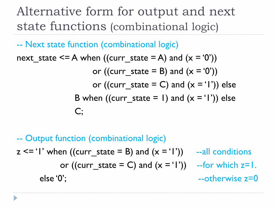
Alternative form for output and next state functions (combinational logic)-- Next state function (combinational logic)next_state <= A when ((curr_state = A) and (x = ‘0’))
or ((curr_state = B) and (x = ‘0’)) or ((curr_state = C) and (x = ‘1’)) else
B when ((curr_state = 1) and (x = ‘1’)) elseC;
-- Output function (combinational logic)z <= ‘1’ when ((curr_state = B) and (x = ‘1’)) --all conditions
or ((curr_state = C) and (x = ‘1’)) --for which z=1.else ‘0’; --otherwise z=0
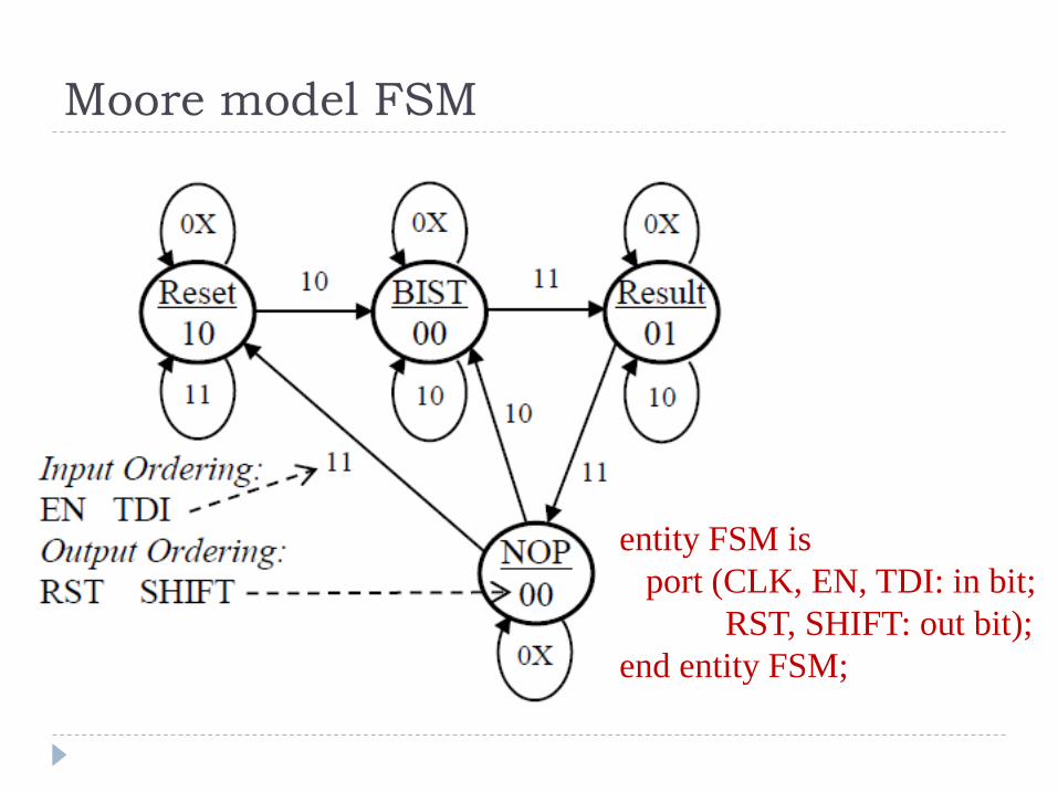
Moore model FSM
entity FSM is port (CLK, EN, TDI: in bit;
RST, SHIFT: out bit); end entity FSM;

architecture RTL of FSM is type STATES is (Reset, BIST, Result, NOP); -- abstract state namessignal CS: STATES; -- current state
begin SYNC: process (CLK) begin -- change states on falling edge of CLK
if (CLK’event and CLK=’0’) thenif (EN = ‘1’) then -- change only if EN = 1
if (CS = Reset) then if (TDI=’0’) then CS <= BIST; end if; --EN,TDI = 10
elsif (CS = BIST) then if (TDI=’1’) then CS <= Result; end if; --EN,TDI = 11
elsif (CS = Result) then if (TDI=’1’) then CS <= NOP; end if; --EN,TDI = 11
elsif (CS = NOP) then if (TDI=’0’) then CS <= BIST; --EN,TDI = 10
else CS <= Reset; --EN,TDI = 11end if;
end if; end if; end if; end process SYNC;
(Outputs on next slide)
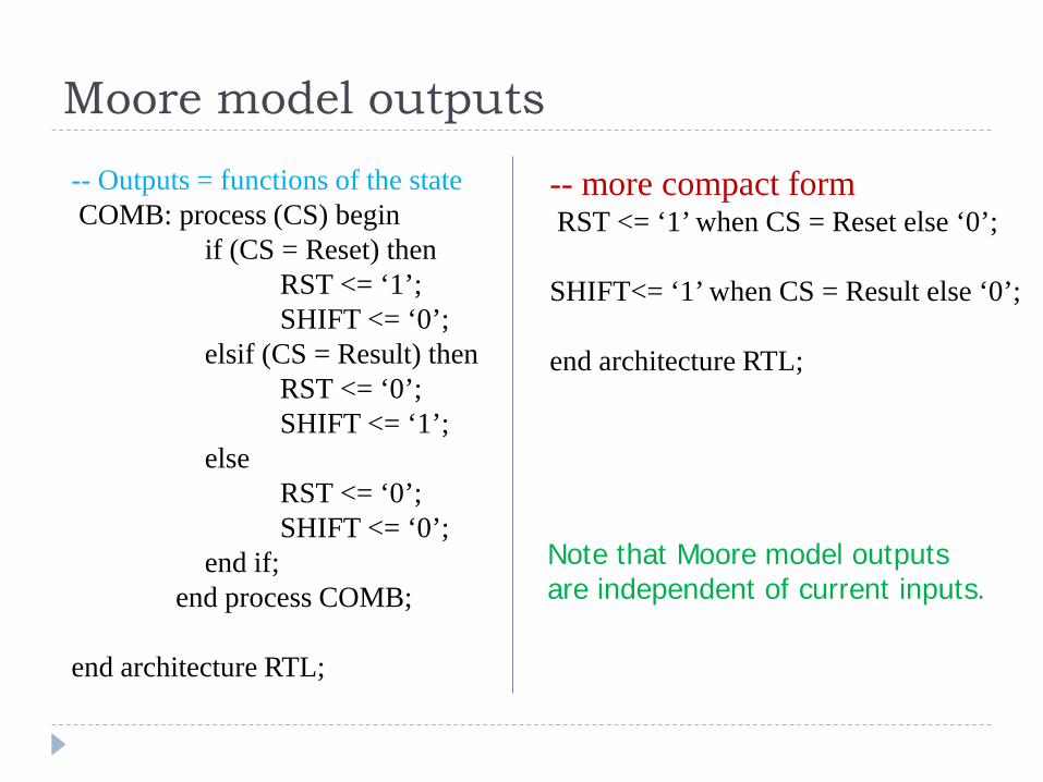
-- Outputs = functions of the stateCOMB: process (CS) begin
if (CS = Reset) then RST <= ‘1’; SHIFT <= ‘0’;
elsif (CS = Result) then RST <= ‘0’; SHIFT <= ‘1’;
elseRST <= ‘0’; SHIFT <= ‘0’;
end if; end process COMB;
end architecture RTL;
-- more compact formRST <= ‘1’ when CS = Reset else ‘0’;
SHIFT<= ‘1’ when CS = Result else ‘0’;
end architecture RTL;
Moore model outputs
Note that Moore model outputsare independent of current inputs.