vessel 1a nii – june 30th 2016 - cmap2 inspection … · · 2016-10-03procedure number #102...
TRANSCRIPT

Silverwing UK Ltd.
Asset Inspection Report Location Swansea Plant
Inspection Type AUT Vessel External
Job Number #90122
Procedure Number #102
Equipment Used RMS300
Inspected By
Silverwing UK Ltd John Smith David Smith
Authorised By John Smith
Vessel 1A NII – June 30th 2016 RMS Vessel Inspection

Inspection Report : Vessel 1A NII RMS Inspection
Page 2 of 61
CContents Scope of Work and Survey Goals ................................................................................................................................ 4
Rapid motion scanner (RMS) Introduction .................................................................................................................. 7
Summary .................................................................................................................................................................. 9
Layout ‘Vessel 1A External’ Material Thickness ....................................................................................................... 12
Layout ‘Vessel 1A External’ Surface ........................................................................................................................ 13
Layout ‘Vessel 1A External’ Amplitude ................................................................................................................... 14
Layout ‘Vessel 1A External’ Material Thickness with Coating ................................................................................... 15
Area ‘Large area of Laminations’ Material Thickness ............................................................................................... 16
Area ‘Large area of Laminations’ Surface ................................................................................................................ 19
Area ‘Large area of Laminations’ Amplitude ........................................................................................................... 20
Area ‘Large area of Laminations’ Material Thickness with Coating........................................................................... 21
Area ‘350mm x 830mm area of Laminations’ Material Thickness ............................................................................ 22
Area ‘350mm x 830mm area of Laminations’ Surface .............................................................................................. 23
Area ‘350mm x 830mm area of Laminations’ Amplitude ......................................................................................... 24
Area ‘350mm x 830mm area of Laminations’ Material Thickness with Coating ........................................................ 25
Area ‘310mm x 260mm area of Laminations’ Material Thickness ............................................................................ 26
Area ‘310mm x 260mm area of Laminations’ Surface .............................................................................................. 28
Area ‘310mm x 260mm area of Laminations’ Amplitude ......................................................................................... 29
Area ‘310mm x 260mm area of Laminations’ Material Thickness with Coating ........................................................ 30
Area ‘32mm x 12mm defect’ Material Thickness ...................................................................................................... 31
Area ‘32mm x 12mm defect’ Surface ....................................................................................................................... 33
Area ‘32mm x 12mm defect’ Amplitude .................................................................................................................. 34
Area ‘32mm x 12mm defect’ Material Thickness with Coating ................................................................................. 35
Area ‘56mm x 16mm & 64mm x 8mm areas with 50% wall thickness remaining’ Material Thickness ........................ 36
Area ‘56mm x 16mm & 64mm x 8mm areas with 50% wall thickness remaining’ Surface ......................................... 38
Area ‘56mm x 16mm & 64mm x 8mm areas with 50% wall thickness remaining’ Amplitude .................................... 39
Area ‘56mm x 16mm & 64mm x 8mm areas with 50% wall thickness remaining’ Material Thickness with Coating .... 40
Area ‘56mm x 12mm area with 50-60% remaining wall thickness’ Material Thickness ............................................. 41
Area ‘56mm x 12mm area with 50-60% remaining wall thickness’ Surface ............................................................... 43
Area ‘56mm x 12mm area with 50-60% remaining wall thickness’ Amplitude .......................................................... 44
Area ‘56mm x 12mm area with 50-60% remaining wall thickness’ Material Thickness with Coating ......................... 45
Area ‘Coating breakdown area 1’ Surface ............................................................................................................... 46
Scan ‘Scan 1 - 1’ Material Thickness ........................................................................................................................ 47
Scan ‘Scan 1 - 2’ Material Thickness ........................................................................................................................ 48
Scan ‘Scan 1 - 3’ Material Thickness ........................................................................................................................ 49
Scan ‘Scan 2 - 1’ Material Thickness ........................................................................................................................ 50
Scan ‘Scan 2 - 2’ Material Thickness ........................................................................................................................ 51
Scan ‘Scan 3 - 1’ Material Thickness ........................................................................................................................ 52

Inspection Report : Vessel 1A NII RMS Inspection
Page 3 of 61
Scan ‘Scan 3 - 2’ Material Thickness ........................................................................................................................ 53
Scan ‘Scan 4 - 1’ Material Thickness ........................................................................................................................ 54
Scan ‘Scan 4 - 2’ Material Thickness ........................................................................................................................ 55
Scan ‘Scan 5 - 1’ Material Thickness ........................................................................................................................ 56
Scan ‘Scan 6 - 3’ Material Thickness ........................................................................................................................ 57
Scan ‘Scan 11 - 2’ Material Thickness ...................................................................................................................... 58
Scan ‘Scan 13 - 1’ Material Thickness ...................................................................................................................... 59
Scan ‘Scan 14 - 1’ Material Thickness ...................................................................................................................... 60
Photographs ........................................................................................................................................................... 61

Inspection Report : Vessel 1A NII RMS Inspection
Page 4 of 61
SScope of Work and Survey Goals
Bulk Fuel Installation ~ Swansea Plant
Required scope of work:
Carry out an external survey of the shell plates using RMS300 system. The inspection will consist of an ultrasonic thickness survey of all vertical shell plates where access permits.
Carry out a visual inspection of all accessible external welds.
Carry out visual / ultrasonic survey of the external nozzles and manways.
Carry out an ultrasonic corrosion survey of external shell to nozzle interfaces.
Comment on the condition of external fixed pipework, saddle supports and other relevant tank features.
Survey Goals:
The attached report documents the findings of the examination performed on June 28th ~30th 2016
The Report provides an evaluation using data collected during the survey.
Data was collected to provide information on the tanks present and continued usage.
I. To detect and size remaining material at the Lower and Upper tanks.
II. To detect size and map areas of internal / external originating corrosion.
III. To consider characteristic, severity and corrosion rates of external pitting as far as is practicable.
IV. To record ultrasonic thickness measurements of all shell plates in order to obtain their nominal thickness.
V. To conduct an ultrasonic corrosion scan at the immediate shell plate area surrounding all Nozzles, as far as is practicable.
VI. General visual inspection to note external nozzle, saddle support etc. condition.
Survey Method:
The RMS shell survey was conducted at a resolution of 10 x 2 (mm) classified as corrosion detection. Any areas of significant interest were additionally scanned at a resolution of 2 x 2 (mm) classified as corrosion mapping.

Inspection Report : Vessel 1A NII RMS Inspection
Page 5 of 61
Any significant external pitting could be analysed by the RMS system (due to the increase in the delay line / water path).
Shell Plate areas not accessed by the RMS system were systematically monitored by ‘A’ Scan Flaw detector to identify internal corrosion loss, if any.
All Nozzles and Manways were visually and ultrasonically (where conditions allowed) examined.
The following equipment was utilized during the inspection;
Silverwing RMS 300 system. (Serial Nos. 7777777)
Pit Gauge. (Serial Nos. PG999)
Silverwing UK Ltd provided the following personnel:
John Smith ~ EEMUA 159 (10UK/02TA/360) Assessor.
API 653 (583) Assessor.
PCN level II (3175) Technician.
David Smith ~ PCN level II (3110) Technician.
Report authorised by;
J Smith …………………………………………
Dated …………………………………

Inspection Report : Vessel 1A NII RMS Inspection
Page 6 of 61
Equipment
Item Description Serial No. Software Version
Unit
RMS2 300 3112847461 RMS 3.1
Probes
Serial No Frequency Diameter
7120892 5 MHz Focal length = 50mm Probe diameter = 8mm
Laptop Model Serial No Software Version
ASUS F175 9182912019 RMS 3.1

Inspection Report : Vessel 1A NII RMS Inspection
Page 7 of 61
RRapid motion scanner (RMS) Introduction
The Rapid motion Scanner (RMS) is a high speed remote access ultrasonic corrosion mapping system which can inspect ferrous materials and pipe work. The RMS2 system is a crawler and control system which outputs encoder pulses and ultrasonic signals. In order to generate a C-scan map the use of a third party data capture system, capable of transmitting / receiving ultrasonic signals and processing the encoder information is required. The system can operate at a high capture speed and is capable of interpreting ultrasonic signals at speeds of 730mm per second when set a resolution of 2mm or greater. The minimum resolution the system can inspect is 0.5mm.
Colour palette Figure 1
The C-Scan image of this scan shown in figure 1 indicates a change in wall thickness as a variation in colour. The relationship between material thickness and colour is shown by the colour palette shown alongside the C-Scan. This palette has a thickness range of 0 to 9mm as indicated by the numbers down the right hand side of the colour palette.
Figure 2
We can see in the C-scan image in Figure 1. This is a way of showing us or mapping out corrosion areas within a material, providing us with an overall thickness of the material (Dark blue Area). As this area is giving us our thickest part of the material, we can then say this will be our nominal thickness area(s). This will be safe to assume that there is no material loss in these areas.
The A-scan image in Figure 2 shows us 4 Signals on the screen. The first signal to the far left is the top surface (Where the signal firsts meets the Plate material). The signal has had to travel through a water column (Starting from the initial pulse at point 0mm. This method of ultrasonics is used with many immersion techniques and irrigated

Inspection Report : Vessel 1A NII RMS Inspection
Page 8 of 61
systems such as the RMS system. The second signal is called the 1st back wall echo (BWE). This is where the pulse has now travelled through the material from the first signal and refracted back to the probe. This now gives us our first thickness reading. (See gate 1 in light blue). Finally the third signal is called our 2nd back wall echo (BWE). This is just a repeat signal of gate 1 (See Figure 1). The point between gate 1 and gate 2 is giving us our actual material thickness (not including the coating) see gate 2 in yellow, this is now our True Thickness of the material (Echo to Echo).
The following report generated in CMAP shows 4 different CScan views:
Material Thickness with Coating (calculated from gates 1st back wall echo – Reference),
Material Thickness (calculated from gates 2nd back wall echo – 1st back wall echo),
Amplitude (calculated from the highest amplitude signal within the amplitude gate),
Surface profile (calculated from the top surface marker to the Reference gate).

Inspection Report : Vessel 1A NII RMS Inspection
Page 9 of 61
SSummary Item Name Measurements / Notes Area: Vessel 1A External/Large area of Laminations
Minimum Maximum Average Material Thickness 3.63 mm 25.97 mm 23.82 mm Surface 0.01 mm 2.98 mm 0.57 mm Amplitude 1.57 % 100 % 93.91 % Material Thickness with Coating
9.88 mm 27.96 mm 24.6 mm
Area: Vessel 1A External/350mm x 830mm area of Laminations
Minimum Maximum Average Material Thickness 12.96 mm 25.97 mm 24.26 mm Surface 0.06 mm 8.52 mm 1.55 mm Amplitude 1.57 % 100 % 78.58 % Material Thickness with Coating
10.23 mm 29.99 mm 25.03 mm
Area: Vessel 1A External/310mm x 260mm area of Laminations
Minimum Maximum Average Material Thickness 12.96 mm 25.97 mm 24.16 mm Surface 0.06 mm 8.22 mm 1.35 mm Amplitude 1.57 % 100 % 76.25 % Material Thickness with Coating
10.23 mm 29.81 mm 24.98 mm
Area: Vessel 1A External/32mm x 12mm defect
Minimum Maximum Average Material Thickness 4.34 mm 25.97 mm 25.23 mm Surface 0.01 mm 7.87 mm 0.38 mm Amplitude 1.57 % 100 % 89.11 % Material Thickness with Coating
10.23 mm 29.33 mm 26.18 mm
Area: Vessel 1A External/56mm x 16mm & 64mm x 8mm areas with 50% wall thickness remaining
Minimum Maximum Average Material Thickness 13.25 mm 25.97 mm 25.25 mm Surface 0.36 mm 2.74 mm 1.17 mm Amplitude 1.57 % 100 % 66.67 % Material Thickness with Coating
13.92 mm 27.43 mm 26.32 mm
Area: Vessel 1A External/56mm x 12mm area with 50-60% remaining wall thickness
Minimum Maximum Average Material Thickness 12.96 mm 25.97 mm 25.45 mm Surface 0.06 mm 8.22 mm 1.77 mm Amplitude 2.35 % 100 % 80.11 % Material Thickness with Coating
10.23 mm 29.93 mm 26.55 mm
Area: Vessel 1A External/Coating breakdown area 1
Minimum Maximum Average Surface 0.06 mm 7.63 mm 0.89 mm
Scan: Vessel 1A External/Scan 1 - 1
Minimum Maximum Average Material Thickness 12.96 mm 25.97 mm 25.14 mm
Scan: Vessel 1A External/Scan 1 - 2
Minimum Maximum Average Material Thickness 12.96 mm 25.97 mm 25.32 mm
Scan: Vessel 1A External/Scan 1 - 3
Minimum Maximum Average Material Thickness 12.96 mm 25.97 mm 25.05 mm
Scan: Vessel 1A External/Scan 1 - 4
Minimum Maximum Average Material Thickness 12.96 mm 25.97 mm 24.96 mm
Scan: Vessel 1A External/Scan 2 - 1
Minimum Maximum Average Material Thickness 12.96 mm 25.97 mm 23.96 mm
Scan: Vessel 1A External/Scan 2 - 2
Minimum Maximum Average Material Thickness 12.96 mm 25.97 mm 25.12 mm

Inspection Report : Vessel 1A NII RMS Inspection
Page 10 of 61
Item Name Measurements / Notes Scan: Vessel 1A External/Scan 2 - 3
Minimum Maximum Average Material Thickness 12.96 mm 25.97 mm 24.86 mm
Scan: Vessel 1A External/Scan 3 - 1
Minimum Maximum Average Material Thickness 12.96 mm 25.97 mm 24.51 mm
Scan: Vessel 1A External/Scan 3 - 2
Minimum Maximum Average Material Thickness 12.96 mm 25.97 mm 25.18 mm
Scan: Vessel 1A External/Scan 3 - 3
Minimum Maximum Average Material Thickness 12.96 mm 25.97 mm 24.89 mm
Scan: Vessel 1A External/Scan 4 - 1
Minimum Maximum Average Material Thickness 12.96 mm 25.97 mm 24.9 mm
Scan: Vessel 1A External/Scan 4 - 2
Minimum Maximum Average Material Thickness 3.63 mm 25.94 mm 25.46 mm
Scan: Vessel 1A External/Scan 4 - 3
Minimum Maximum Average Material Thickness 12.96 mm 25.97 mm 25.01 mm
Scan: Vessel 1A External/Scan 5 - 1
Minimum Maximum Average Material Thickness 12.96 mm 25.97 mm 25.05 mm
Scan: Vessel 1A External/Scan 5 - 2
Minimum Maximum Average Material Thickness 13.02 mm 25.97 mm 25.02 mm
Scan: Vessel 1A External/Scan 5 - 3
Minimum Maximum Average Material Thickness 12.96 mm 25.97 mm 25.05 mm
Scan: Vessel 1A External/Scan 5 - 4
Minimum Maximum Average Material Thickness 13.19 mm 25.97 mm 24.76 mm
Scan: Vessel 1A External/Scan 6 - 1
Minimum Maximum Average Material Thickness 13.02 mm 25.97 mm 25.27 mm
Scan: Vessel 1A External/Scan 6 - 2
Minimum Maximum Average Material Thickness 12.96 mm 25.97 mm 25.02 mm
Scan: Vessel 1A External/Scan 6 - 3
Minimum Maximum Average Material Thickness 12.96 mm 25.97 mm 24.95 mm
Scan: Vessel 1A External/Scan 7 - 1
Minimum Maximum Average Material Thickness 12.96 mm 25.97 mm 25.05 mm
Scan: Vessel 1A External/Scan 7 - 2
Minimum Maximum Average Material Thickness 12.96 mm 25.97 mm 25.13 mm
Scan: Vessel 1A External/Scan 8 - 1
Minimum Maximum Average Material Thickness 12.96 mm 25.97 mm 25.17 mm
Scan: Vessel 1A External/Scan 8 - 2
Minimum Maximum Average Material Thickness 12.96 mm 25.97 mm 25.25 mm
Scan: Vessel 1A External/Scan 9 - 1
Minimum Maximum Average Material Thickness 13.02 mm 25.97 mm 25.15 mm
Scan: Vessel 1A External/Scan 9 - 2
Minimum Maximum Average Material Thickness 12.96 mm 25.97 mm 25.12 mm
Scan: Vessel 1A External/Scan 10 - 1
Minimum Maximum Average Material Thickness 12.96 mm 25.97 mm 25.26 mm
Scan: Vessel 1A External/Scan 10 - 2
Minimum Maximum Average Material Thickness 13.49 mm 25.97 mm 25.05 mm
Scan: Vessel 1A External/Scan 11 - 1
Minimum Maximum Average Material Thickness 12.96 mm 25.97 mm 25.04 mm
Scan: Vessel 1A External/Scan 11 - 2
Minimum Maximum Average Material Thickness 12.96 mm 25.97 mm 25.21 mm
Scan: Vessel 1A External/Scan 12 - 1
Minimum Maximum Average Material Thickness 12.96 mm 25.97 mm 25.01 mm
Scan: Vessel 1A External/Scan 13 - 1
Minimum Maximum Average Material Thickness 12.96 mm 25.97 mm 24.77 mm

Inspection Report : Vessel 1A NII RMS Inspection
Page 11 of 61
Item Name Measurements / Notes Scan: Vessel 1A External/Scan 13 - 2
Minimum Maximum Average Material Thickness 12.96 mm 25.97 mm 24.98 mm
Scan: Vessel 1A External/Scan 14 - 1
Minimum Maximum Average Material Thickness 12.96 mm 25.97 mm 24.84 mm

Inspection Report : Vessel 1A NII RMS Inspection
Page 12 of 61
Layout ‘Vessel 1A External’ Material Thickness
mm
The layout above indicates the full area covered by the inspection, The C-Scan data is colourised to indicate wall thickness. The relationship between material thickness and colour is shown by the colour palette shown alongside the C-Scan. Areas of concern are identified by rectangular boxes in the layout and these are addressed individually in the report identifying minimum, maximum and average thicknesses for the Area and any notes from the Inspector. Where appropriate A-Scan, B-Scan and Profile views are also included to provide further details.
Inspection Report : Vessel 1A NII RMS Inspection
Page 13 of 61
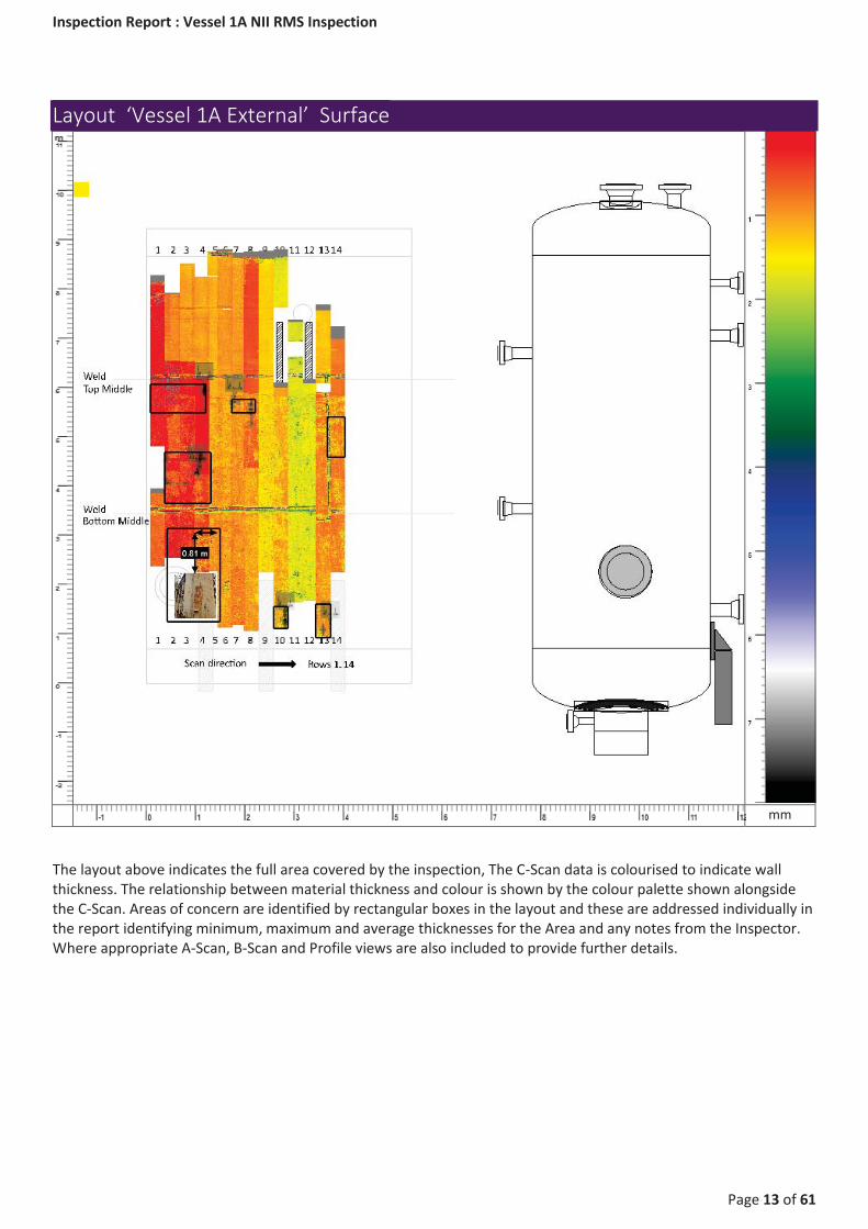
Layout ‘Vessel 1A External’ Surface
mm
The layout above indicates the full area covered by the inspection, The C-Scan data is colourised to indicate wall thickness. The relationship between material thickness and colour is shown by the colour palette shown alongside the C-Scan. Areas of concern are identified by rectangular boxes in the layout and these are addressed individually in the report identifying minimum, maximum and average thicknesses for the Area and any notes from the Inspector. Where appropriate A-Scan, B-Scan and Profile views are also included to provide further details.

Inspection Report : Vessel 1A NII RMS Inspection
Page 14 of 61
Layout ‘Vessel 1A External’ Amplitude
%
The layout above indicates the full area covered by the inspection, The C-Scan data is colourised to indicate wall thickness. The relationship between material thickness and colour is shown by the colour palette shown alongside the C-Scan. Areas of concern are identified by rectangular boxes in the layout and these are addressed individually in the report identifying minimum, maximum and average thicknesses for the Area and any notes from the Inspector. Where appropriate A-Scan, B-Scan and Profile views are also included to provide further details.

Inspection Report : Vessel 1A NII RMS Inspection
Page 15 of 61
Layout ‘Vessel 1A External’ Material Thickness with Coating
mm
The layout above indicates the full area covered by the inspection, The C-Scan data is colourised to indicate wall thickness. The relationship between material thickness and colour is shown by the colour palette shown alongside the C-Scan. Areas of concern are identified by rectangular boxes in the layout and these are addressed individually in the report identifying minimum, maximum and average thicknesses for the Area and any notes from the Inspector. Where appropriate A-Scan, B-Scan and Profile views are also included to provide further details.

Inspection Report : Vessel 1A NII RMS Inspection
Page 16 of 61
Area ‘Large area of Laminations’ Material Thickness Position: (376, 4704) mm Size: (946, 1034) mm Minimum: 3.63 mm Maximum: 25.97 mm Average: 23.82 mm
Area of Laminations found 150mm above the bottom weld
mm

Inspection Report : Vessel 1A NII RMS Inspection
Page 17 of 61
AScan Marker 5: Sample AScan taken from the large area of laminations
Measurements 1st BWE - Reference gate = 13.81 mm Amplitude gate = 100 % Second Back Wall - 1st BWE = 13.57 mm Top Surface - Reference gate = 0.19 mm
BScan BScan over cluster of Laminations
BScan BScan over 44mm x 16mm size defect

Inspection Report : Vessel 1A NII RMS Inspection
Page 18 of 61
Profile Profile over 44mm x 16mm size defect found within area

Inspection Report : Vessel 1A NII RMS Inspection
Page 19 of 61
Area ‘Large area of Laminations’ Surface Position: (376, 4704) mm Size: (946, 1034) mm Minimum: 0.01 mm Maximum: 2.98 mm Average: 0.57 mm
mm

Inspection Report : Vessel 1A NII RMS Inspection
Page 20 of 61
Area ‘Large area of Laminations’ Amplitude Position: (376, 4704) mm Size: (946, 1034) mm Minimum: 1.57 % Maximum: 100 % Average: 93.91 %
%

Inspection Report : Vessel 1A NII RMS Inspection
Page 21 of 61
Area ‘Large area of Laminations’ Material Thickness with Coating Position: (376, 4704) mm Size: (946, 1034) mm Minimum: 9.88 mm Maximum: 27.96 mm Average: 24.6 mm
The possible presence of significant laminations in the pipe material was assessed by viewing the AScan and detecting ultrasonic reflections other than normal back wall echo. Evidence of laminations was detected. As a result the section examined failed the requirements of the API 510 code related to vessel inspections.
mm

Inspection Report : Vessel 1A NII RMS Inspection
Page 22 of 61
Area ‘350mm x 830mm area of Laminations’ Material Thickness Position: (3696, 5426) mm Size: (354, 834) mm Minimum: 12.96 mm Maximum: 25.97 mm Average: 24.26 mm
mm

Inspection Report : Vessel 1A NII RMS Inspection
Page 23 of 61
Area ‘350mm x 830mm area of Laminations’ Surface Position: (3696, 5426) mm Size: (354, 834) mm Minimum: 0.06 mm Maximum: 8.52 mm Average: 1.55 mm
mm

Inspection Report : Vessel 1A NII RMS Inspection
Page 24 of 61
Area ‘350mm x 830mm area of Laminations’ Amplitude Position: (3696, 5426) mm Size: (354, 834) mm Minimum: 1.57 % Maximum: 100 % Average: 78.58 %
%

Inspection Report : Vessel 1A NII RMS Inspection
Page 25 of 61
Area ‘350mm x 830mm area of Laminations’ Material Thickness with Coating Position: (3696, 5426) mm Size: (354, 834) mm Minimum: 10.23 mm Maximum: 29.99 mm Average: 25.03 mm
mm

Inspection Report : Vessel 1A NII RMS Inspection
Page 26 of 61
Area ‘310mm x 260mm area of Laminations’ Material Thickness Position: (3446.95, 1610) mm Size: (307.15, 681.92) mm Minimum: 12.96 mm Maximum: 25.97 mm Average: 24.16 mm
mm

Inspection Report : Vessel 1A NII RMS Inspection
Page 27 of 61
AScan Marker 1: Sample AScan taken from 310mm x 260mm area of Laminations
Measurements 1st BWE - Reference gate = 11.96 mm Amplitude gate = 100 % Second Back Wall - 1st BWE = 13.49 mm Top Surface - Reference gate = 1.61 mm

Inspection Report : Vessel 1A NII RMS Inspection
Page 28 of 61
Area ‘310mm x 260mm area of Laminations’ Surface Position: (3446.95, 1610) mm Size: (307.15, 681.92) mm Minimum: 0.06 mm Maximum: 8.22 mm Average: 1.35 mm
mm

Inspection Report : Vessel 1A NII RMS Inspection
Page 29 of 61
Area ‘310mm x 260mm area of Laminations’ Amplitude Position: (3446.95, 1610) mm Size: (307.15, 681.92) mm Minimum: 1.57 % Maximum: 100 % Average: 76.25 %
%

Inspection Report : Vessel 1A NII RMS Inspection
Page 30 of 61
Area ‘310mm x 260mm area of Laminations’ Material Thickness with Coating Position: (3446.95, 1610) mm Size: (307.15, 681.92) mm Minimum: 10.23 mm Maximum: 29.81 mm Average: 24.98 mm
mm

Inspection Report : Vessel 1A NII RMS Inspection
Page 31 of 61
Area ‘32mm x 12mm defect’ Material Thickness Position: (90, 6090) mm Size: (1130, 580) mm Minimum: 4.34 mm Maximum: 25.97 mm Average: 25.23 mm
mm

Inspection Report : Vessel 1A NII RMS Inspection
Page 32 of 61
AScan Marker 2 : Sample AScan taken from Area 32mm x 12mm defect
Measurements 1st BWE - Reference gate = 18.03 mm Amplitude gate = 100 % Second Back Wall - 1st BWE = 18.21 mm Top Surface - Reference gate = 0.1 mm
BScan
Profile
Inspection Report : Vessel 1A NII RMS Inspection
Page 33 of 61
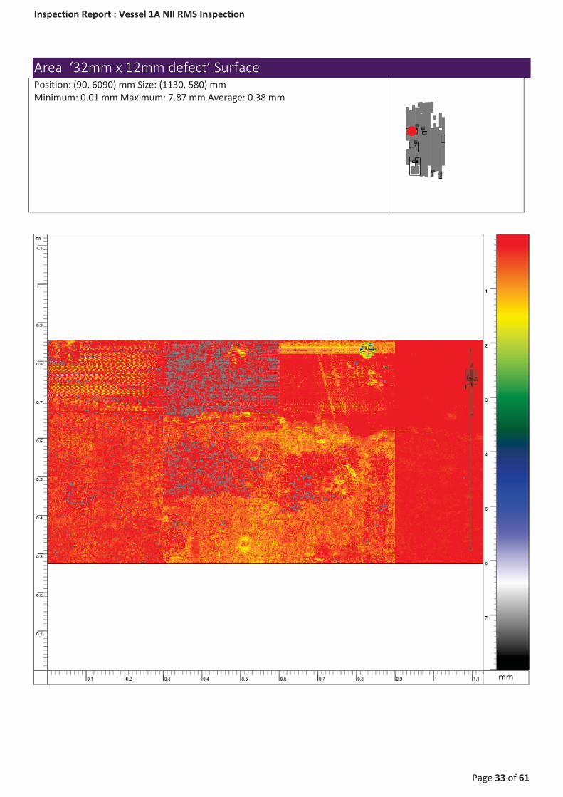
Area ‘32mm x 12mm defect’ Surface Position: (90, 6090) mm Size: (1130, 580) mm Minimum: 0.01 mm Maximum: 7.87 mm Average: 0.38 mm
mm

Inspection Report : Vessel 1A NII RMS Inspection
Page 34 of 61
Area ‘32mm x 12mm defect’ Amplitude Position: (90, 6090) mm Size: (1130, 580) mm Minimum: 1.57 % Maximum: 100 % Average: 89.11 %
%

Inspection Report : Vessel 1A NII RMS Inspection
Page 35 of 61
Area ‘32mm x 12mm defect’ Material Thickness with Coating Position: (90, 6090) mm Size: (1130, 580) mm Minimum: 10.23 mm Maximum: 29.33 mm Average: 26.18 mm
mm

Inspection Report : Vessel 1A NII RMS Inspection
Page 36 of 61
Area ‘56mm x 16mm & 64mm x 8mm areas with 50% wall thickness remaining’ Material Thickness Position: (1748, 5780) mm Size: (474, 282) mm Minimum: 13.25 mm Maximum: 25.97 mm Average: 25.25 mm
mm

Inspection Report : Vessel 1A NII RMS Inspection
Page 37 of 61
AScan Marker 4
Measurements 1st BWE - Reference gate = 15.18 mm Amplitude gate = 100 % Second Back Wall - 1st BWE = 14.78 mm Top Surface - Reference gate = 1.31 mm
BScan

Inspection Report : Vessel 1A NII RMS Inspection
Page 38 of 61
Area ‘56mm x 16mm & 64mm x 8mm areas with 50% wall thickness remaining’ Surface Position: (1748, 5780) mm Size: (474, 282) mm Minimum: 0.36 mm Maximum: 2.74 mm Average: 1.17 mm
mm

Inspection Report : Vessel 1A NII RMS Inspection
Page 39 of 61
Area ‘56mm x 16mm & 64mm x 8mm areas with 50% wall thickness remaining’ Amplitude Position: (1748, 5780) mm Size: (474, 282) mm Minimum: 1.57 % Maximum: 100 % Average: 66.67 %
%
Inspection Report : Vessel 1A NII RMS Inspection
Page 40 of 61
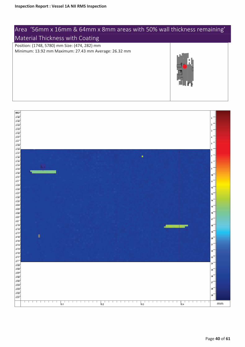
Area ‘56mm x 16mm & 64mm x 8mm areas with 50% wall thickness remaining’ Material Thickness with Coating Position: (1748, 5780) mm Size: (474, 282) mm Minimum: 13.92 mm Maximum: 27.43 mm Average: 26.32 mm
mm

Inspection Report : Vessel 1A NII RMS Inspection
Page 41 of 61
Area ‘56mm x 12mm area with 50-60% remaining wall thickness’ Material Thickness Position: (2590, 1570) mm Size: (300, 450) mm Minimum: 12.96 mm Maximum: 25.97 mm Average: 25.45 mm
mm
Inspection Report : Vessel 1A NII RMS Inspection
Page 42 of 61
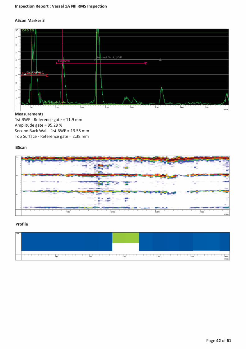
AScan Marker 3
Measurements 1st BWE - Reference gate = 11.9 mm Amplitude gate = 95.29 % Second Back Wall - 1st BWE = 13.55 mm Top Surface - Reference gate = 2.38 mm
BScan
Profile

Inspection Report : Vessel 1A NII RMS Inspection
Page 43 of 61
Area ‘56mm x 12mm area with 50-60% remaining wall thickness’ Surface Position: (2590, 1570) mm Size: (300, 450) mm Minimum: 0.06 mm Maximum: 8.22 mm Average: 1.77 mm
mm

Inspection Report : Vessel 1A NII RMS Inspection
Page 44 of 61
Area ‘56mm x 12mm area with 50-60% remaining wall thickness’ Amplitude Position: (2590, 1570) mm Size: (300, 450) mm Minimum: 2.35 % Maximum: 100 % Average: 80.11 %
%

Inspection Report : Vessel 1A NII RMS Inspection
Page 45 of 61
Area ‘56mm x 12mm area with 50-60% remaining wall thickness’ Material Thickness with Coating Position: (2590, 1570) mm Size: (300, 450) mm Minimum: 10.23 mm Maximum: 29.93 mm Average: 26.55 mm
mm

Inspection Report : Vessel 1A NII RMS Inspection
Page 46 of 61
Area ‘Coating breakdown area 1’ Surface Position: (440, 3153.28) mm Size: (1070, 1890) mm Minimum: 0.06 mm Maximum: 7.63 mm Average: 0.89 mm
Captioned photograph shows area of coating break down below the bottom weld
mm

Inspection Report : Vessel 1A NII RMS Inspection
Page 47 of 61
Scan ‘Scan 1 - 1’ Material Thickness Position: (240, 3177.22) mm Size: (300, 1600) mm Minimum: 12.96 mm Maximum: 25.97 mm Average: 25.14 mm
mm

Inspection Report : Vessel 1A NII RMS Inspection
Page 48 of 61
Scan ‘Scan 1 - 2’ Material Thickness Position: (240, 5816.43) mm Size: (300, 2000) mm Minimum: 12.96 mm Maximum: 25.97 mm Average: 25.32 mm
mm

Inspection Report : Vessel 1A NII RMS Inspection
Page 49 of 61
Scan ‘Scan 1 - 3’ Material Thickness Position: (240, 6906.43) mm Size: (300, 2000) mm Minimum: 12.96 mm Maximum: 25.97 mm Average: 25.05 mm
mm

Inspection Report : Vessel 1A NII RMS Inspection
Page 50 of 61
Scan ‘Scan 2 - 1’ Material Thickness Position: (540, 3553.16) mm Size: (300, 2000) mm Minimum: 12.96 mm Maximum: 25.97 mm Average: 23.96 mm
mm

Inspection Report : Vessel 1A NII RMS Inspection
Page 51 of 61
Scan ‘Scan 2 - 2’ Material Thickness Position: (540, 5553.16) mm Size: (300, 2000) mm Minimum: 12.96 mm Maximum: 25.97 mm Average: 25.12 mm
mm

Inspection Report : Vessel 1A NII RMS Inspection
Page 52 of 61
Scan ‘Scan 3 - 1’ Material Thickness Position: (840, 3546.43) mm Size: (300, 2000) mm Minimum: 12.96 mm Maximum: 25.97 mm Average: 24.51 mm
mm

Inspection Report : Vessel 1A NII RMS Inspection
Page 53 of 61
Scan ‘Scan 3 - 2’ Material Thickness Position: (840, 5536.43) mm Size: (300, 2000) mm Minimum: 12.96 mm Maximum: 25.97 mm Average: 25.18 mm
mm

Inspection Report : Vessel 1A NII RMS Inspection
Page 54 of 61
Scan ‘Scan 4 - 1’ Material Thickness Position: (1140, 3256.43) mm Size: (300, 2000) mm Minimum: 12.96 mm Maximum: 25.97 mm Average: 24.9 mm
mm

Inspection Report : Vessel 1A NII RMS Inspection
Page 55 of 61
Scan ‘Scan 4 - 2’ Material Thickness Position: (1140, 5256.43) mm Size: (300, 2000) mm Minimum: 3.63 mm Maximum: 25.94 mm Average: 25.46 mm
mm

Inspection Report : Vessel 1A NII RMS Inspection
Page 56 of 61
Scan ‘Scan 5 - 1’ Material Thickness Position: (1400, 3283.28) mm Size: (300, 2000) mm Minimum: 12.96 mm Maximum: 25.97 mm Average: 25.05 mm
mm
Inspection Report : Vessel 1A NII RMS Inspection
Page 57 of 61
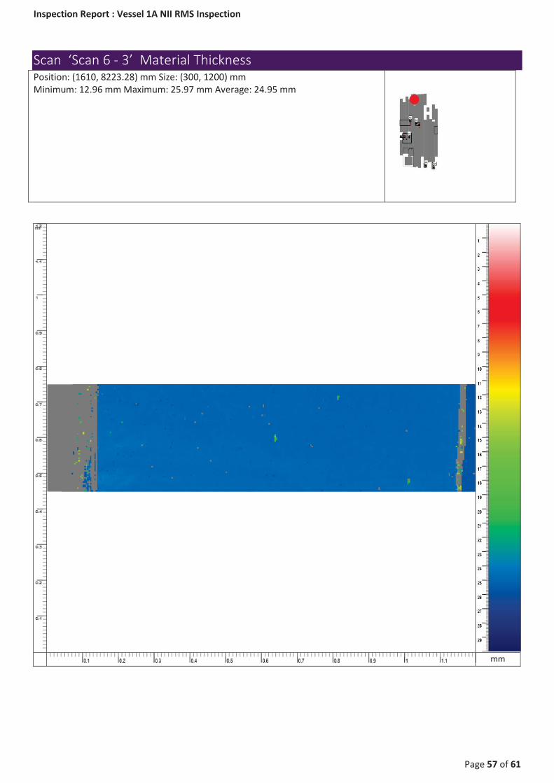
Scan ‘Scan 6 - 3’ Material Thickness Position: (1610, 8223.28) mm Size: (300, 1200) mm Minimum: 12.96 mm Maximum: 25.97 mm Average: 24.95 mm
mm

Inspection Report : Vessel 1A NII RMS Inspection
Page 58 of 61
Scan ‘Scan 11 - 2’ Material Thickness Position: (3040, 7178.28) mm Size: (300, 450) mm Minimum: 12.96 mm Maximum: 25.97 mm Average: 25.21 mm
mm

Inspection Report : Vessel 1A NII RMS Inspection
Page 59 of 61
Scan ‘Scan 13 - 1’ Material Thickness Position: (3600, 3426.43) mm Size: (300, 5000) mm Minimum: 12.96 mm Maximum: 25.97 mm Average: 24.77 mm
mm

Inspection Report : Vessel 1A NII RMS Inspection
Page 60 of 61
Scan ‘Scan 14 - 1’ Material Thickness Position: (3900, 4756.43) mm Size: (300, 5000) mm Minimum: 12.96 mm Maximum: 25.97 mm Average: 24.84 mm
mm

Inspection Report : Vessel 1A NII RMS Inspection
Page 61 of 61
Photographs