vertx user manual - · pdf fileicr vertx –user manual safety information read and...
TRANSCRIPT
VERTXUSER MANUAL
iCR VERTX –User Manual
Foreword
Proprietary Notice and Disclaimer
The information herein disclosed is the property of iCRco., Inc. Information in this docu-ment is subject to change without notice and does not represent a commitment by iCRco toincorporate changes or improvements in units previously sold or shipped.
No part of this document may be reproduced or transmitted in any form, electronicor mechanical, including photocopying and recording, for any purpose other than thepurchaser’s own use without the express written permission of iCRco.
Copyright
Copyright c© iCRco Inc. 2003 - 2010All rights reserved.
Trademarks
iCR 2600 R©, iCR 1000 R©, iCR 1000 Dual R©, iCR 2600 R©, iCR 2600 Dual R©, iCR 2600SF R©, iCRVet R©, iCR CR Vet Dual R©, iCR Mobile R©, iCR 1-D R©, iCR Chiro R©, iCR Chiro Dual R©, iCR3600 R©, iCR 3600SF R©, iCR VERTX R©,iDR R©,www.icrcompany.com and QPC XSCAN32 arethe trademarks of iCRco. All other trademarks are the property of their respective owners,and are hereby acknowledged.
Terms
Any one of the following iCR products will be referred to as the “CR unit” throughoutthis document: iCR 1000 R©, iCR 1000 Dual R©, iCR 2600 R©, iCR 2600 Dual R©, iCR 2600SF R©,iCR 3600 R©, iCR Vet R©, iCR Vet Dual R©, iCR Mobile R©, iCR 1-D R©, iCR Chiro R©, iCR ChiroDual R© iCR VERTX R© Any one of the following iCR products will be referred to as “iCRdual unit” throughout this document: iCR 1000 Dual R©, iCR 2600 Dual R©, iCR Vet Dual R©,iCR Chiro Dual R©Any one of the following iCR products will be referred to as “iCR desktopunit” throughout this document: iCR VERTX R©. The iDR R©will be referred to as the “DRunit” throughout this document.
c©2007-2009Confidential and ProprietaryProperty of iCRco, Inc.
i of 63 Document # VTX-01A Rev DMarch 22, 2010

iCR VERTX –User Manual
Contact Information
iCRco., Inc. USAAddress: 2580 West 237th Street, Torrance, CA, 90505Phone: +1.310.921.9559Fax: +1.310.542.7236Email: [email protected]: http://www.icrcompany.com
iCRco., Inc. EuropeAddress: 31a Ridlerstrasse, 80339 Munich, GermanyPhone: +49.89.2555.757.150Email: [email protected]: http://www.icrcompany.com
VertX Information
Please Enter the details of the VertX system here:
Serial Number:
Date Purchased:
Interface Type: USB 2.0
c©2007-2009Confidential and ProprietaryProperty of iCRco, Inc.
ii of 63 Document # VTX-01A Rev DMarch 22, 2010
iCR VERTX –User Manual
Safety Information
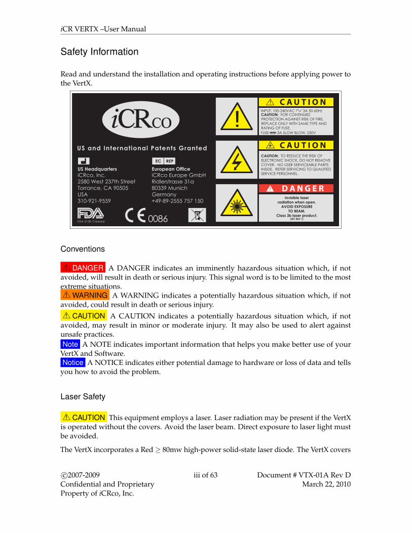
Read and understand the installation and operating instructions before applying power tothe VertX.
C A U T I O N
C A U T I O N
D A N G E R
CAUTION: FOR CONTINUED PROTECTION AGAINST RISK OF FIRE, REPLACE ONLY WITH SAME TYPE AND RATING OF FUSE.
CAUTION: TO REDUCE THE RISK OF ELECTRONIC SHOCK, DO NOT REMOVE COVER. NO USER SERVICEABLE PARTS INSIDE. REFER SERVICING TO QUALIFIED SERVICE PERSONNEL.
Invisible laser radiation when open.
AVOID EXPOSURETO BEAM.
Class 3b laser product.(IEC 825-1)
3A SLOW BLOW, 250VFUSE
INPUT: 100-240VAC 3A 50-60Hz
Conventions
! DANGER A DANGER indicates an imminently hazardous situation which, if notavoided, will result in death or serious injury. This signal word is to be limited to the mostextreme situations.! WARNING A WARNING indicates a potentially hazardous situation which, if not
avoided, could result in death or serious injury.! CAUTION A CAUTION indicates a potentially hazardous situation which, if not
avoided, may result in minor or moderate injury. It may also be used to alert againstunsafe practices.Note A NOTE indicates important information that helps you make better use of your
VertX and Software.Notice A NOTICE indicates either potential damage to hardware or loss of data and tells
you how to avoid the problem.
Laser Safety
! CAUTION This equipment employs a laser. Laser radiation may be present if the VertXis operated without the covers. Avoid the laser beam. Direct exposure to laser light mustbe avoided.
The VertX incorporates a Red ≥ 80mw high-power solid-state laser diode. The VertX covers
c©2007-2009Confidential and ProprietaryProperty of iCRco, Inc.
iii of 63 Document # VTX-01A Rev DMarch 22, 2010

iCR VERTX –User Manual
protect the service person from direct exposure to laser light. These covers will protecta user/service person only if they are properly installed. Covers must be removed andreplaced by properly trained service personnel. Contact iCRco if there are any issues withthe covers being damaged or replacement covers are needed.
Electrical Hazards
! WARNING This equipment is operated with hazardous voltages which can shock, burn,or cause death.
Notice The VertX must be connected to a uninterruptible power supply (UPS). Failure touse a (UPS) will void the warranty.
The equipment must be serviced by properly trained technicians certified by iCRco, Inc. Donot connect the VertX with a damaged or sub-standard power cable. Do not use an extensioncord with this device. The VertX should be properly grounded and power connectionsinspected to ensure safe operation. Use at least a 1300VA (780W) uninterruptible powersupply (UPS) with this device, as it is sensitive to variations in power.
Malfunctioning Equipment
If any iCRco product shows signs of malfunction, discontinue the use of the productimmediately and contact Technical Support at 310-921-9559.
FCC Notification
This equipment generates, uses, and can radiate radio frequency energy, and if not installedproperly, can cause interference with radio communications.
Mammography Use
The VertX is not intended for Mammography use.
c©2007-2009Confidential and ProprietaryProperty of iCRco, Inc.
iv of 63 Document # VTX-01A Rev DMarch 22, 2010
iCR VERTX –User Manual
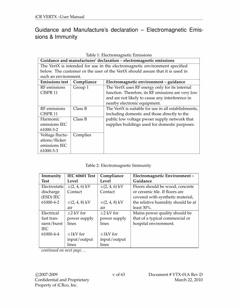
Guidance and Manufacture’s declaration – Electromagnetic Emis-sions & Immunity
Table 1: Electromagnetic EmissionsGuidance and manufactures’ declaration – electromagnetic emissionsThe VertX is intended for use in the electromagnetic environment specifiedbelow. The customer or the user of the VertX should assure that it is used insuch an environment.Emissions test Compliance Electromagnetic environment – guidanceRF emissionsCISPR 11
Group 1 The VertX uses RF energy only for its internalfunction. Therefore, its RF emissions are very lowand are not likely to cause any interference innearby electronic equipment.
RF emissionsCISPR 11
Class B The VertX is suitable for use in all establishments,including domestic and those directly to thepublic low voltage pwoer supply network thatsupplies buildings used for domestic purposes.
Harmonicemissions IEC61000-3-2
Class B
Voltage fluctu-ations/flickeremissions IEC61000-3-3
Complies
Table 2: Electromagnetic Immunity
ImmunityTest
IEC 60601 TestLevel
ComplianceLevel
Electromagnetic Environment –Guidance
Electrostaticdischarge(ESD) IEC61000-4-2
±(2, 4, 6) kVContact
±(2, 4, 8) kVair
±(2, 4, 6) kVContact
±(2, 4, 8) kVair
Floors should be wood, concreteor ceramic tile. If floors arecovered with synthetic material,the relative humidity should be atleast 30%.
Electricalfast tran-sient/burstIEC61000-4-4
±2 kV forpower supplylines
±1kV forinput/outputlines
±2 kV forpower supplylines
±1kV forinput/outputlines
Mains power quality should bethat of a typical commercial orhospital environment.
continued on next page. . .
c©2007-2009Confidential and ProprietaryProperty of iCRco, Inc.
v of 63 Document # VTX-01A Rev DMarch 22, 2010

iCR VERTX –User Manual
Table 2 continued. . .ImmunityTest
IEC 60601 TestLevel
ComplianceLevel
Electromagnetic Environment –Guidance
Surge IEC61000-4-5
±1 kVdifferentialmode
±2 kVcommon mode
±1 kVdifferentialmode
±2 kVcommon mode
Mains power quality should bethat of a typical commercial orhospital environment.
Voltagedips, shortinterrup-tions andvoltagevariationson powersupplyinput linesIEC61000-4-11
<5% UT
(>95% dip inUT ) for 0.5cycle.
40% UT (60%dip in UT ) for5 cycles.
70% UT (30%dip in UT ) for25 cycles.
<5% UT
(>95% dip inUT ) for 5 sec.
<5% UT
(>95% dip inUT ) for 0.5cycle.
40% UT (60%dip in UT ) for5 cycles.
70% UT (30%dip in UT ) for25 cycles.
<5% UT
(>95% dip inUT ) for 5 sec.
Mains power quality should bethat of a typical commercial orhospital environment. If the userof the VertX requires continuedoperation during power mainsinterruptions, it is recommendedthat the VertX be powered froman uninterruptible pwoer supplyor a battery.
Powerfrequency(50/60Hz)magneticfield IEC61000-4-8
3A/m 3A/m Power frequency magnetic fieldsshould be at levels characteristicof a typical location in a typicalcommercial or hospitalenvironment.
NOTE: UT is the a.c. mains voltage prior to application of the test level.continued on next page. . .
c©2007-2009Confidential and ProprietaryProperty of iCRco, Inc.
vi of 63 Document # VTX-01A Rev DMarch 22, 2010
iCR VERTX –User Manual
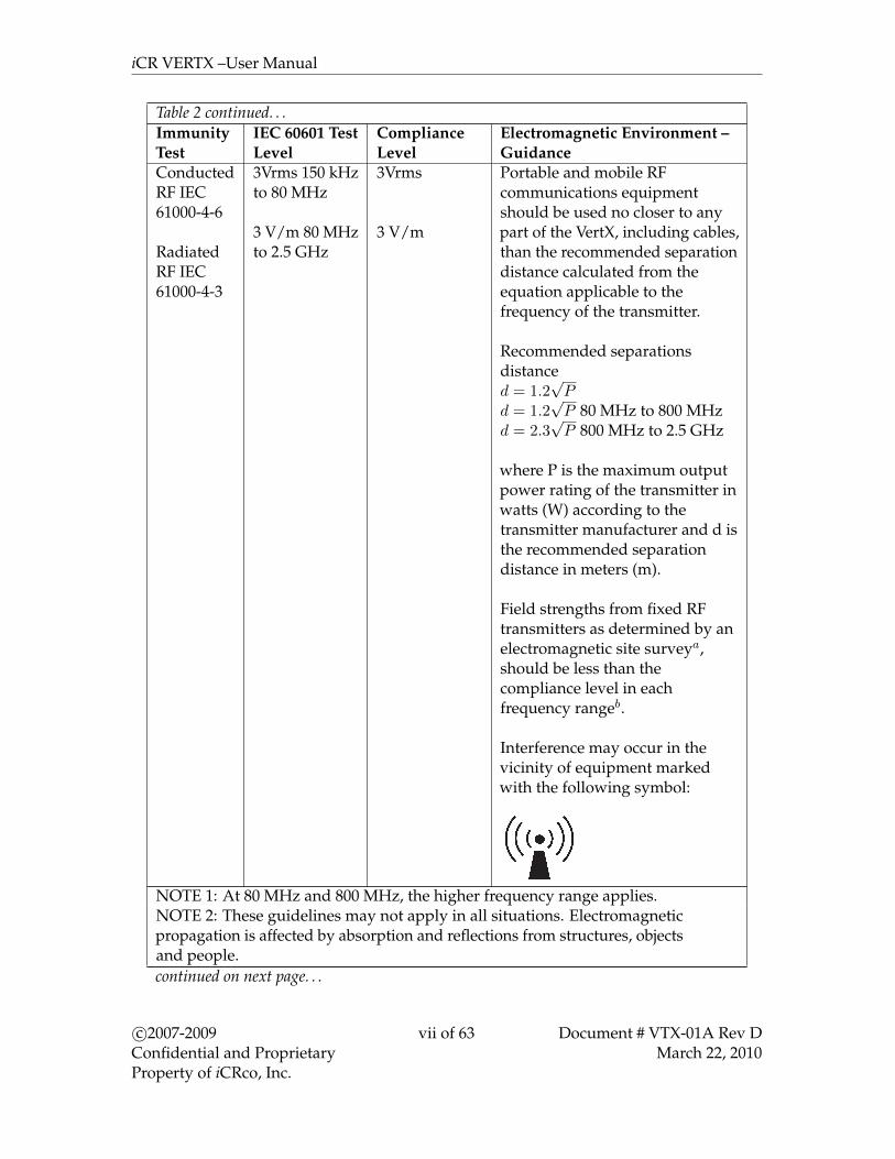
Table 2 continued. . .ImmunityTest
IEC 60601 TestLevel
ComplianceLevel
Electromagnetic Environment –Guidance
ConductedRF IEC61000-4-6
RadiatedRF IEC61000-4-3
3Vrms 150 kHzto 80 MHz
3 V/m 80 MHzto 2.5 GHz
3Vrms
3 V/m
Portable and mobile RFcommunications equipmentshould be used no closer to anypart of the VertX, including cables,than the recommended separationdistance calculated from theequation applicable to thefrequency of the transmitter.
Recommended separationsdistanced = 1.2
√P
d = 1.2√P 80 MHz to 800 MHz
d = 2.3√P 800 MHz to 2.5 GHz
where P is the maximum outputpower rating of the transmitter inwatts (W) according to thetransmitter manufacturer and d isthe recommended separationdistance in meters (m).
Field strengths from fixed RFtransmitters as determined by anelectromagnetic site surveya,should be less than thecompliance level in eachfrequency rangeb.
Interference may occur in thevicinity of equipment markedwith the following symbol:
NOTE 1: At 80 MHz and 800 MHz, the higher frequency range applies.NOTE 2: These guidelines may not apply in all situations. Electromagneticpropagation is affected by absorption and reflections from structures, objectsand people.continued on next page. . .
c©2007-2009Confidential and ProprietaryProperty of iCRco, Inc.
vii of 63 Document # VTX-01A Rev DMarch 22, 2010

iCR VERTX –User Manual
Table 2 continued. . .ImmunityTest
IEC 60601 TestLevel
ComplianceLevel
Electromagnetic Environment –Guidance
a Field strengths from fixed transmitters, such as base stations for radio(cellular/cordless) telephones and land mobile radios, amateur radio, AMand FM radio broadcast and TV broadcast cannot be predicted theoreticallywith accuracy. To assess the electromagnetic environment due to fixed RFtransmitters, an electromagnetic site survey should be considered. If themeasured field strength in the location where the VertX is used exceeds theapplicable RF compliance levels above, the VertX should be observed toverify normal operation. If abnormal performance is observed, additionalmeasures may be necessary, such as reorienting or relocating the VertX.b Over the frequency range 150 kHz to 80 MHz, field strengths should beless than 3 V/m.
iCRco Warranty
iCRco, Inc. (“iCRco”) values your business and always strives to provide high qualityproducts and services. All iCRco products are provided with an initial warranty so thehardware and software are covered from the date of purchase. This limited warrantysolely applies to new products manufactured by or for iCRco and originally purchasedfrom iCRco or an authorized dealer of iCRco products for your own use. In addition, anextended warranty is available for most new and recently purchased iCRco products for anadditional charge.
Hardware Limited Warranty
iCRco warrants its hardware products to be free of defects in materials and workmanshipfor a period of one (1) year from the date of original shipment from iCRco subject to thelimitations set forth herein. If a product proves to be defective in material or workmanshipduring the warranty period, iCRco will, at its sole option, repair or replace the productwith a similar product. Repaired and replacement products may be or include refurbishedor remanufactured parts. Any replacement item assumes the remaining warranty period ofthe original product. iCRco provides no warranty for any third party hardware or softwareincluded with any product or later acquired.
Software Limited Warranty/Support
iCRco warrants that its QPC XSCAN32, Captera, and/or ClarityPACS software originallyprovided with any product will substantially conform to iCRco’s specifications and thatthe media, not including hard drives, on which the software is furnished will be free from
c©2007-2009Confidential and ProprietaryProperty of iCRco, Inc.
viii of 63 Document # VTX-01A Rev DMarch 22, 2010

iCR VERTX –User Manual
defects in materials and workmanship under normal use for a period of one (1) year fromthe date of original shipment from iCRco. iCRco’s sole obligation under this warranty islimited to making reasonable efforts to ensure such conformity and to supply the consumerwith a corrected version of the software as soon as it is practical after the consumer hasnotified iCRco of any non conformity. iCRco does not warrant that the operation of anysoftware will be uninterrupted, glitch or error free or that functions contained in thesoftware will operate in the combinations which may be selected for use by the user ormeet the user’s requirements. This limited software warranty will be void if the software ismodified without the written approval of iCRco or is used outside of the recommendedparameters or equipment. iCRco does not provide any warranty or support for any othersoftware.
iCRco agrees to provide one (1) year of telephonic and/or e-mail based support for QPCXSCAN32, Captera, and/or ClarityPACS software originally provided with any new iCRcoproduct from the date of original shipment from iCRco. All software support shall belimited to making reasonable efforts to resolve iCRco software issues and shall be limitedto iCRco’s regular business hours. In addition, iCRco will provide revisions and upgradesto its software upon request (when available) during the first year after the software wasoriginally shipped from the iCRco factory. The initial support period will include supportvia remote login software (GoToMeeting), only if the customer has access to the Internetfrom that PC and only if the customer agrees iCRco shall have no liability in connectionwith its support efforts. Remote login software allows iCRco technical support to remotelyaccess the customer’s PC via the Internet for the purposes of rendering technical support.Please note that this warranty, including software support, does not include computerhardware, third party software or operating system or network issues, which are outsidethe control of iCRco.
Warranty Product Technical Requirements
iCRco requires that all DR, CR, Scanner and/or products requiring PCs be fitted andinstalled with a 1500VA (1500W) uninterruptible power supply (“UPS”). iCRco recommendsthe APC 1000 specification UPS or equivalent. For warranty evaluation and service, iCRcorequires the customer to provide an Internet connection (DSL or Dial-up) or the minimumof a phone line accessible by an extension cord to the product enabling iCRco technicians toperform remote diagnostics on installed equipment. In addition, each iCRco product mustbe installed, maintained and operated in accordance with the respective product manual.Failure to comply with these requirements will result in a voided warranty claim.
Requesting Warranty Service
For information on obtaining warranty service, call iCRco’s customer support at (310)921-9559. In order to evaluate a warranty service request, iCRco requires the following infor-mation: the iCRco serial number of the product, a detailed description of the problem,customer name and contact information; product location and operating conditions; a copy
c©2007-2009Confidential and ProprietaryProperty of iCRco, Inc.
ix of 63 Document # VTX-01A Rev DMarch 22, 2010
iCR VERTX –User Manual
of the purchase documents, and sufficient information and authorization, including a liabil-ity release as to any loss of data (that should always be backed up), software or networkinjury, or downtime, allowing iCRco technicians remote access to the product. Product maynot be returned to iCRco without first obtaining a Return Material Authorization (“RMA”)number from iCRco. Prior to providing an RMA, iCRco may require remote access to theproduct. If iCRco determines that the product may be defective, is under warranty andnecessitates a return to iCRco for service, an RMA number and instructions for return ofthe product will be given. iCRco is not responsible for any unauthorized returned product,i.e. one for which an RMA number has not been issued by iCRco.
Warranty service requires all authorized returns be shipped to the iCRco factory prepaidand insured. All such authorized returns are the customer’s responsibility. For productssold and located within the United States, iCRco will pay for return shipping.
Products being returned are only to be shipped in iCRco approved shipping containers.The original box and packaging materials are approved and should be kept for movingand/or shipping the product. Approved packaging my also be purchased from iCRco foran additional charge. iCRco shall have no liability nor responsibility for warranty serviceto any product that is not shipped in an iCRco approved shipping container or that isdamaged from incorrect packaging or damaged during shipping.
Additional Warranty Limitations and Extent of Warranty
This warranty does not apply if the product has been damaged by accident, misuse orabuse. In addition, warranty service does not include the repair of failures or defects causedby: unauthorized attachments to any iCRco product, unsuitable physical or operatingenvironment, maintenance or repair by anyone other than iCRco or the iCRco authorizeddealer that sold the product, operation of a product beyond its duty cycle, use of theproduct outside of its specifications, the use of supplies, parts, materials, software, orinterfaces not furnished, authorized or recommended by iCRco. If the product, includingany software has been opened, tampered with, modified or altered in any way withoutwritten authorization by iCRco, the warranty will no longer apply.
This warranty applies only to products manufactured by, or for, iCRco, and that can beidentified by an “iCRco” serial number as originally affixed to the product. Any modifica-tion to the iCRco serial number tag or its attachment to the product shall immediately voidthe warranty.
This warranty is non-transferable and subsequent owners must contact iCRco to establishif the equipment is eligible for an extended warranty.
THERE ARE NO WARRANTIES, EXPRESS OR IMPLIED, WITH RESPECT TO ANY iCRcoPRODUCT OTHER THAN AS SPECIFICALLY SET FORTH HEREIN, AND iCRco SPECIF-ICALLY DISCLAIMS ANY IMPLIED WARRANTIES OR CONDITIONS OF MERCHANTABILITY, FITNESS FOR A PARTICULAR PURPOSE, AND SATISFACTORY QUALITY.ANY WARRANTIES THAT MAY NOT BE DISCLAIMED UNDER APPLICABLE LAW
c©2007-2009Confidential and ProprietaryProperty of iCRco, Inc.
x of 63 Document # VTX-01A Rev DMarch 22, 2010
iCR VERTX –User Manual
ARE LIMITED IN DURATION TO THE INITIAL WARRANTY PERIOD AND NO WAR-RANTIES, EXPRESS OR IMPLIED, WILL APPLY AFTER THIS PERIOD. ALL INFORMA-TION, SPECIFICATIONS, PRICES, AND SERVICES ARE SUBJECT TO CHANGE AT ANYTIME WITHOUT NOTICE.
Limitation of Remedies and Liability/Exclusion of Damages
The exclusive remedy for any defective product is limited to the repair or replacement ofthe defective product. iCRco shall have a reasonable time after determining that a defectiveproduct exists to repair or replace a defective product. iCRco’s entire liability for anyproduct is limited to the actual purchase price for the product. This limitation applies evenif iCRco cannot or does not repair or replace any defective product.
IN NO EVENT WILL iCRco BE LIABLE FOR ANY GENERAL, SPECIAL, CONSEQUEN-TIAL OR INCIDENTAL DAMAGES, including but not limited to, damages related tothe loss of use, loss of recorded product, the installation of replacement product, or anyinspection, testing, or redesign caused by any defect or by the repair or replacement ofany product arising from a defect in any product. This exclusion of damages applies evenif the customer advises iCRco or an iCRco dealer of the possiblity of such damages. Thislimitation of remedies also applies to claims against any suppliers or dealers of iCRco. iCRco and itssuppliers’ and dealers’ limitations of remedies are not cumulative. Such suppliers and dealers areintended beneficiaries of this limitation. iCRco is not liable for any claim by or against the customerarising from a third party claim.
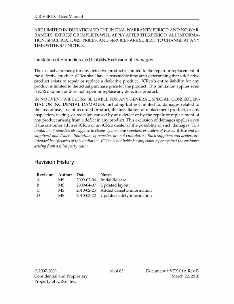
Revision History
Revision Author Date NotesA MS 2009-02-06 Initial ReleaseB MS 2009-04-07 Updated layoutC MS 2010-02-25 Added cassette informationD MS 2010-03-22 Updated safety information
c©2007-2009Confidential and ProprietaryProperty of iCRco, Inc.
xi of 63 Document # VTX-01A Rev DMarch 22, 2010

iCR VERTX –User Manual
Contents
Foreword iContact Information . . . . . . . . . . . . . . . . . . . . . . . . . . . . . . . . . . . iiSafety Information . . . . . . . . . . . . . . . . . . . . . . . . . . . . . . . . . . . . iiiiCRco Warranty . . . . . . . . . . . . . . . . . . . . . . . . . . . . . . . . . . . . . . viii
1 Introduction 11.1 Overview . . . . . . . . . . . . . . . . . . . . . . . . . . . . . . . . . . . . . . . 1
2 Pre-Installation 22.1 Voltage Requirements . . . . . . . . . . . . . . . . . . . . . . . . . . . . . . . 22.2 Environmental . . . . . . . . . . . . . . . . . . . . . . . . . . . . . . . . . . . . 22.3 Connectivity and power supply . . . . . . . . . . . . . . . . . . . . . . . . . . 22.4 Physical requirements . . . . . . . . . . . . . . . . . . . . . . . . . . . . . . . 22.5 Systems Specifications . . . . . . . . . . . . . . . . . . . . . . . . . . . . . . . 3
3 Driver and Software Installation 43.1 Installing USB drivers . . . . . . . . . . . . . . . . . . . . . . . . . . . . . . . 43.2 Installing QPC XSCAN32 . . . . . . . . . . . . . . . . . . . . . . . . . . . . . 43.3 Initializing the VERTX Driver . . . . . . . . . . . . . . . . . . . . . . . . . . . 6
4 Hardware Installation 84.1 Unpacking Instructions . . . . . . . . . . . . . . . . . . . . . . . . . . . . . . . 84.2 PC Specifications . . . . . . . . . . . . . . . . . . . . . . . . . . . . . . . . . . 84.3 VERTX USB 2.0 Installation . . . . . . . . . . . . . . . . . . . . . . . . . . . . 84.4 Power Switch Locations . . . . . . . . . . . . . . . . . . . . . . . . . . . . . . 94.5 Installing AC Power Cord . . . . . . . . . . . . . . . . . . . . . . . . . . . . . 94.6 International Power Cable . . . . . . . . . . . . . . . . . . . . . . . . . . . . . 104.7 Power and Scan Lights . . . . . . . . . . . . . . . . . . . . . . . . . . . . . . . 10
5 System Operation 115.1 Power-Up . . . . . . . . . . . . . . . . . . . . . . . . . . . . . . . . . . . . . . 115.2 Cassette Handling . . . . . . . . . . . . . . . . . . . . . . . . . . . . . . . . . . 11
5.2.1 Overview . . . . . . . . . . . . . . . . . . . . . . . . . . . . . . . . . . 115.2.2 Weight/Force Applied to Cassette . . . . . . . . . . . . . . . . . . . . 115.2.3 Cassette Storage . . . . . . . . . . . . . . . . . . . . . . . . . . . . . . . 115.2.4 Cassette Contamination . . . . . . . . . . . . . . . . . . . . . . . . . . 12
5.3 Acquiring an Image . . . . . . . . . . . . . . . . . . . . . . . . . . . . . . . . . 125.4 Schedule of Maintenance . . . . . . . . . . . . . . . . . . . . . . . . . . . . . . 175.5 Periodic Cleaning . . . . . . . . . . . . . . . . . . . . . . . . . . . . . . . . . . 18
5.5.1 Cleaning the Outside of the VertX . . . . . . . . . . . . . . . . . . . . 185.5.2 Cassette Cleaning . . . . . . . . . . . . . . . . . . . . . . . . . . . . . . 18
c©2007-2009Confidential and ProprietaryProperty of iCRco, Inc.
xii of 63 Document # VTX-01A Rev DMarch 22, 2010
iCR VERTX –User Manual
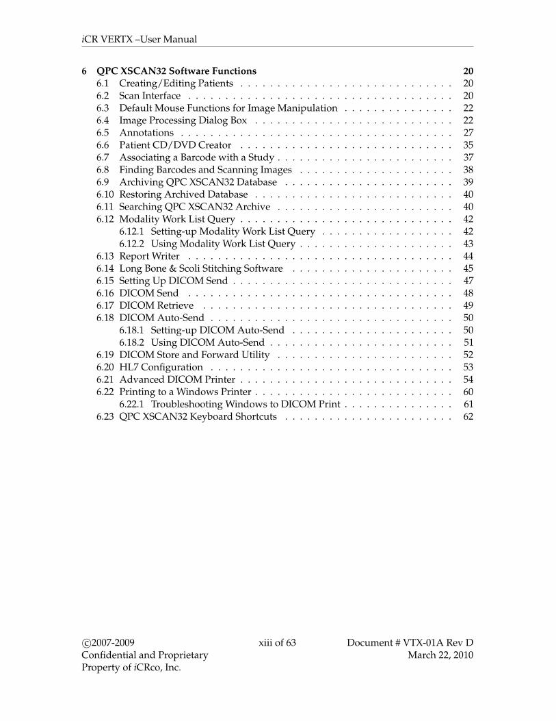
6 QPC XSCAN32 Software Functions 206.1 Creating/Editing Patients . . . . . . . . . . . . . . . . . . . . . . . . . . . . . 206.2 Scan Interface . . . . . . . . . . . . . . . . . . . . . . . . . . . . . . . . . . . . 206.3 Default Mouse Functions for Image Manipulation . . . . . . . . . . . . . . . 226.4 Image Processing Dialog Box . . . . . . . . . . . . . . . . . . . . . . . . . . . 226.5 Annotations . . . . . . . . . . . . . . . . . . . . . . . . . . . . . . . . . . . . . 276.6 Patient CD/DVD Creator . . . . . . . . . . . . . . . . . . . . . . . . . . . . . 356.7 Associating a Barcode with a Study . . . . . . . . . . . . . . . . . . . . . . . . 376.8 Finding Barcodes and Scanning Images . . . . . . . . . . . . . . . . . . . . . 386.9 Archiving QPC XSCAN32 Database . . . . . . . . . . . . . . . . . . . . . . . 396.10 Restoring Archived Database . . . . . . . . . . . . . . . . . . . . . . . . . . . 406.11 Searching QPC XSCAN32 Archive . . . . . . . . . . . . . . . . . . . . . . . . 406.12 Modality Work List Query . . . . . . . . . . . . . . . . . . . . . . . . . . . . . 42
6.12.1 Setting-up Modality Work List Query . . . . . . . . . . . . . . . . . . 426.12.2 Using Modality Work List Query . . . . . . . . . . . . . . . . . . . . . 43
6.13 Report Writer . . . . . . . . . . . . . . . . . . . . . . . . . . . . . . . . . . . . 446.14 Long Bone & Scoli Stitching Software . . . . . . . . . . . . . . . . . . . . . . 456.15 Setting Up DICOM Send . . . . . . . . . . . . . . . . . . . . . . . . . . . . . . 476.16 DICOM Send . . . . . . . . . . . . . . . . . . . . . . . . . . . . . . . . . . . . 486.17 DICOM Retrieve . . . . . . . . . . . . . . . . . . . . . . . . . . . . . . . . . . 496.18 DICOM Auto-Send . . . . . . . . . . . . . . . . . . . . . . . . . . . . . . . . . 50
6.18.1 Setting-up DICOM Auto-Send . . . . . . . . . . . . . . . . . . . . . . 506.18.2 Using DICOM Auto-Send . . . . . . . . . . . . . . . . . . . . . . . . . 51
6.19 DICOM Store and Forward Utility . . . . . . . . . . . . . . . . . . . . . . . . 526.20 HL7 Configuration . . . . . . . . . . . . . . . . . . . . . . . . . . . . . . . . . 536.21 Advanced DICOM Printer . . . . . . . . . . . . . . . . . . . . . . . . . . . . . 546.22 Printing to a Windows Printer . . . . . . . . . . . . . . . . . . . . . . . . . . . 60
6.22.1 Troubleshooting Windows to DICOM Print . . . . . . . . . . . . . . . 616.23 QPC XSCAN32 Keyboard Shortcuts . . . . . . . . . . . . . . . . . . . . . . . 62
c©2007-2009Confidential and ProprietaryProperty of iCRco, Inc.
xiii of 63 Document # VTX-01A Rev DMarch 22, 2010

iCR VERTX –User Manual
s1. Introduction
1.1 Overview
The VertX unit is an ultra high resolution Computed Radiography (CR) device. It is designedto scan cassettes containing phosphor screens (CR plates) using patented technology. CRplates are transported past a scanning head without bending or using rollers. This TrueFlat Scan Path c© results in ultra high resolution images with high fidelity across the entireimage. High resolution is achieved from the CR plates by coupling the True Flat ScanPath c©with a high energy laser.
The VertX unit collects 16 bits (65,536 possible gray levels) data that is converted to a DICOM3.0 image and can be stored, viewed, manipulated, and sent to any other storage device,printer, or viewing station through the medical transfer protocol specified by DICOM.This document contains a basic technical overview of the VertX unit and driving softwaresubsystems. A general description of the systems functionality and user interfaces willbe described. Unpacking of the hardware and software installation. This document isintended for users who need to understand the basic principles of operation for the VertXunit.
c©2007-2009Confidential and ProprietaryProperty of iCRco, Inc.
1 of 63 Document # VTX-01A Rev DMarch 22, 2010
iCR VERTX –User Manual
s2. Pre-Installation
2.1 Voltage Requirements
The VERTX unit incorporates an international auto-switching power supply. iCRco employsCE certified medical grade universal power supplies to allow the unit to work between 90to 253V AC 50/60Hz. In order to run the unit with different power types, apply voltageto the power input module at the end of the VERTX unit. For international units, a localpower cord must be used that can handle the power requirements of the unit. A 13A/220Vpower cord is sufficient.
2.2 Environmental
The VERTX unit should not be placed in a room with a film processor present. This willvoid the warranty. The humidity and temperature limits are 20 to 95% non-condensing,and 59◦F to 95◦F (15◦C to 35◦C), operating, respectively.
Installation of the VertX near high magnetic fields may cause the VertX to malfunction.The VertX should not be placed in a room with an MRI, CT, or any other equipment thatproduces high magnetic fields.
The room should have good ventilation. Another factor to consider prior to installing theVertX is dust and particulates in the environment. The VertX is designed to be resistant todust and particulates that may be present at the installation site.
2.3 Connectivity and power supply
The room needs to have wall power and should not be used with an extension cord. Theroom needs to have wall power and should not be used with an extension cord. Use atleast a 1500VA (780W) UPS between the wall power and the VertX. It is also required tohave a network connection for fast technical support. Alternatively, the user must havea phone/fax line that can be connected to the PC as a minimum to comply with iCRcowarranty terms.
2.4 Physical requirements
The VERTX unit requires a stable operating environment. It is important the system isplaced where it will not be susceptible to tipping over or falling. Please ensure that the baseplate is properly installed. Optionally, the VERTX unit can be mounted to the wall or to amobile cart.
c©2007-2009Confidential and ProprietaryProperty of iCRco, Inc.
2 of 63 Document # VTX-01A Rev DMarch 22, 2010
iCR VERTX –User Manual
2.5 Systems Specifications
Cassette Sizes
14x17in, 10x12in (the VERTX uses iCRcodigital X-ray cassettes that comply with allstandards for conventional X-ray cassettes).
Pixels per Line Resolution
3500 (High Resolution) over 14 inches(356mm) 2048 (Normal Resolution) over 14inches (356mm).
Scan Rate
Scan Rate 60 lines/second
Grey Scale Resolution
16 bits (65,536 shades of gray)
Interface
USB 2.0
Dimensions
iCR VERTX: 34.9H x 20W x 6.7D inches
Power Requirements
Domestic: 100 to 120V, 50/60Hz, 3.5AInternational: 220 to 240V, 50/60Hz, 1.75A
Temperature Conditions
59◦F to 95◦F (15◦C to 35◦C) – operating0◦F to 150◦F (-18◦C to 65◦C) – non-operating
Humidity
20 to 95% non-condensing
Vibration/Acceleration
3-4G Max (in shipping)
Altitude
0 to 9,500 ft. - operating
Weight
59 lbs (without accessories)
Warm Up Time
Five (5) minutes.
c©2007-2009Confidential and ProprietaryProperty of iCRco, Inc.
3 of 63 Document # VTX-01A Rev DMarch 22, 2010

iCR VERTX –User Manual
s3. Driver and Software Installation
3.1 Installing USB drivers
USB drivers are automatically installed while installing QPC XSCAN32.
3.2 Installing QPC XSCAN32
QPC XSCAN32 software comes bundled with the VERTX unit. This software package willallow the user to interface with the VERTX unit.Note If you have QPC XSCAN32 already installed on your computer and it is running
while you are trying to install the new version, an error will appear in the install process.Please close QPC XSCAN32 and reinstall the new version.
1. Insert the media containing the QPC XSCAN32 installer into the computer. Navigateto the QPC XSCAN32 folder.
2. Launch the QPC XSCAN32 installer by double clicking Setup.exe.
3. Click Next at the welcome screen.
4. Click Yes to agree to the Software License Agreement.
5. Make sure both QPC XSCAN32 Software and Software Key Driver boxes are checked,then click Next.
c©2007-2009Confidential and ProprietaryProperty of iCRco, Inc.
4 of 63 Document # VTX-01A Rev DMarch 22, 2010
iCR VERTX –User Manual
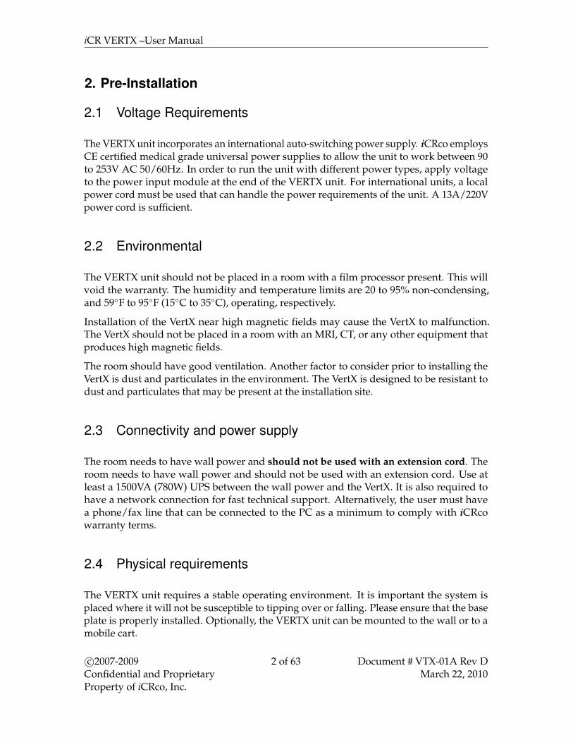
6. Select Scanning Station or Reading Station depend on the use, then click Next to con-tinue.
7. Select the appropriate modality, then click Next to continue.
8. The Destination Folder should be set to C:\Xscan32 then click Next to continue.
9. The Program Folder name should be set to QPC XSCAN32, then click Next.
c©2007-2009Confidential and ProprietaryProperty of iCRco, Inc.
5 of 63 Document # VTX-01A Rev DMarch 22, 2010

iCR VERTX –User Manual
10. QPC XSCAN32 will begin to install. Be patient while XSCAN32 installs.
11. Insert the USB Dongle into a free USB port if you have not done so already, then clickOK to continue.
12. Click Finish to complete the installation of QPC XSCAN32. The installer will exit.
3.3 Initializing the VERTX Driver
Note This process will need to be repeated for each USB port on the laptop. There are 4USB ports on each laptop.
1. Make sure the VERTX unit is powered on and has the proper USB cable installed.
c©2007-2009Confidential and ProprietaryProperty of iCRco, Inc.
6 of 63 Document # VTX-01A Rev DMarch 22, 2010

iCR VERTX –User Manual
2. Plug the USB cable into the laptop.
3. The New Hardware Wizard dialog will pop up. Select the option Install the softwareautomatically, then click Next.
4. A driver signing warning will appear. Click Continue Anyway.
5. The installation process is finished. Click Finish to finish the installation.
c©2007-2009Confidential and ProprietaryProperty of iCRco, Inc.
7 of 63 Document # VTX-01A Rev DMarch 22, 2010

iCR VERTX –User Manual
s4. Hardware Installation
4.1 Unpacking Instructions
1. Open the box from the top.
2. Remove any small accessories loaded into the top of the box.
3. With at least two (2) people, lift the VertX out of the box.! CAUTION Always practice proper heavy lifting procedures. Failure to practice
proper lifting procedures may result in injury or damage to the unit.
4. Store the box and any foam inserts somewhere safe & dry, so that if the VertX needsto be shipped again, there are packing materials available.
4.2 PC Specifications
The minimum requirements for the Acquisition computer are as follows:Processor: Pentium DRAM: 2 GB or moreOS: Windows XPHDD: 250 GB or more
4.3 VERTX USB 2.0 Installation
The USB 2.0 port is located on the upper, right-hand side of the operator when facing thefront of the VERTX unit. Plug a standard USB 2.0 cable into the VERTX USB port and theninto the PC.
c©2007-2009Confidential and ProprietaryProperty of iCRco, Inc.
8 of 63 Document # VTX-01A Rev DMarch 22, 2010
iCR VERTX –User Manual
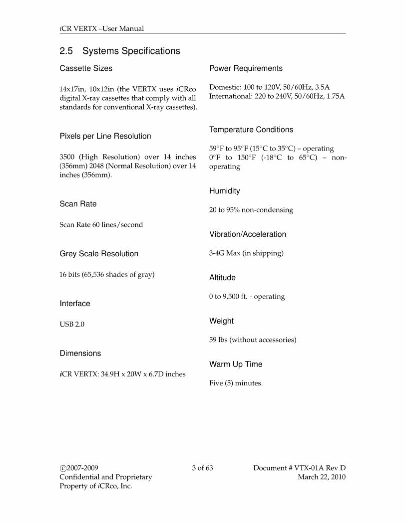
4.4 Power Switch Locations
The power switch for theVERTX unit is located on thefront in the lower right handside of the unit, shown herewith the front cowling removed.
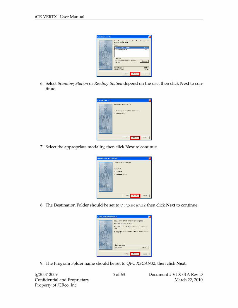
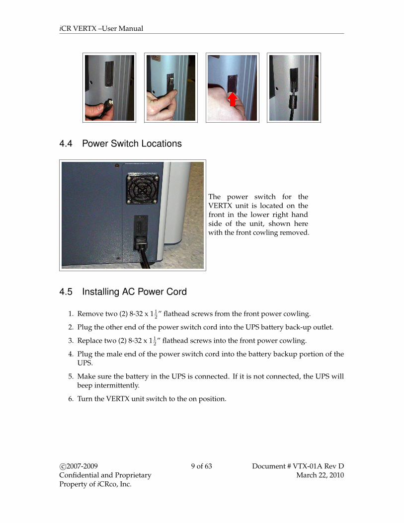
4.5 Installing AC Power Cord
1. Remove two (2) 8-32 x 112” flathead screws from the front power cowling.
2. Plug the other end of the power switch cord into the UPS battery back-up outlet.
3. Replace two (2) 8-32 x 112” flathead screws into the front power cowling.
4. Plug the male end of the power switch cord into the battery backup portion of theUPS.
5. Make sure the battery in the UPS is connected. If it is not connected, the UPS willbeep intermittently.
6. Turn the VERTX unit switch to the on position.
c©2007-2009Confidential and ProprietaryProperty of iCRco, Inc.
9 of 63 Document # VTX-01A Rev DMarch 22, 2010

iCR VERTX –User Manual
4.6 International Power Cable
The VERTX unit utilizes an international IEC grade connector for the power cable. Systemsare shipped with a standard NEMA 5-15 hospital grade cable. The cable needs to bechanged depending on the male end, which varies from country to country.
4.7 Power and Scan Lights
The power and scan lights are located in thefront of the VERTX unit near the top right side.When the unit is powered on, the green lightis illuminated. While the unit is scanning theyellow light will blink.
c©2007-2009Confidential and ProprietaryProperty of iCRco, Inc.
10 of 63 Document # VTX-01A Rev DMarch 22, 2010

iCR VERTX –User Manual
s5. System Operation
5.1 Power-Up
1. Make sure the power cord is properly installed in the power module.
2. Make sure the power cord is properly installed in the UPS and the UPS is pluggedinto a standard wall outlet.
3. Make sure the USB 2.0 cord is properly installed in the VertX and computer.
4. Power on the computer.
5. Power on the VertX by pressing the power switch.
5.2 Cassette Handling
5.2.1 Overview
Unlike other solutions, the VertX does not allow for contact to the delicate phosphorimaging plate. The hard X-ray cassette is designed to protect the plate and allow for it to beread by the VertX. The delicate imaging plate is embedded within a rigid cassette in such away that nothing touches the plate during the scanning or handling process.
5.2.2 Weight/Force Applied to Cassette
Apply only minimal weight and/or force to the cassette (for example, do not have a patientstand on the cassette for weight-bearing views). Use a weight-bearing cap when necessary.
! WARNING Excessive weight/force may damage the cassette and may cause the CRunit to malfunction. Do not apply excessive weight/force to the cassette.
5.2.3 Cassette Storage
All cassettes should be stored in the cleanest, driest conditions possible. Always storecassettes in a location where they are not likely to be knocked over or damaged. Withcareful handling the cassette plate system should provide years of service as there is noknown lifetime for the phosphors used in the plate system.
c©2007-2009Confidential and ProprietaryProperty of iCRco, Inc.
11 of 63 Document # VTX-01A Rev DMarch 22, 2010
iCR VERTX –User Manual
5.2.4 Cassette Contamination
Should the situation arise where a cassette may come in contact with bodily fluids or othercontaminated materials, place the cassette in a clean plastic bag before exposing the X-ray.This will ensure that the cassette stays clean and usable.
5.3 Acquiring an Image
! WARNING This equipment employs a laser. Avoid the laser beam. Direct eye exposureto laser light must be avoided. Avoid looking down the cassette entry slot.
Note The steps in this section represent a typical CR workflow. Every workflow varies inprocess.
1. Open the dust cover that covers the entry slot.
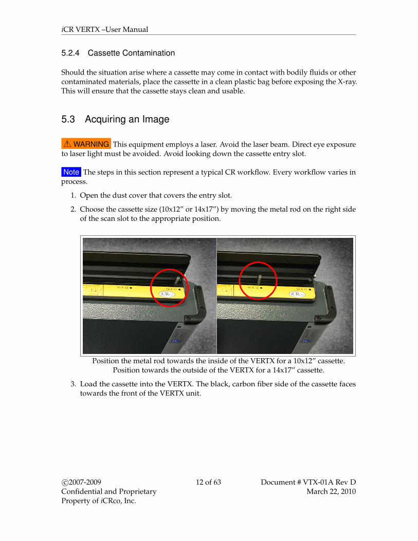
2. Choose the cassette size (10x12” or 14x17”) by moving the metal rod on the right sideof the scan slot to the appropriate position.
Position the metal rod towards the inside of the VERTX for a 10x12” cassette.Position towards the outside of the VERTX for a 14x17” cassette.
3. Load the cassette into the VERTX. The black, carbon fiber side of the cassette facestowards the front of the VERTX unit.
c©2007-2009Confidential and ProprietaryProperty of iCRco, Inc.
12 of 63 Document # VTX-01A Rev DMarch 22, 2010

iCR VERTX –User Manual
! CAUTION Do not use excessive force when loading the cassette! The cassette willnot fit if the orientation is incorrect.
4. Open QPC XSCAN32.
5. Create or edit patient profile. To do this, click New or Edit, respectively.
6. If creating a new patient, enter the relevant patient info, or if editing a patient, changethe information accordingly, then click Save and View.
7. Click on Scan to bring up the Quality Processing Center Scan dialog. (if it is a patientwith no images the scan dialog will automatically appear).
c©2007-2009Confidential and ProprietaryProperty of iCRco, Inc.
13 of 63 Document # VTX-01A Rev DMarch 22, 2010

iCR VERTX –User Manual
8. The iCR Quality Processing Center dialog will appear.
9. Select the anatomy by mousing over the skeleton on the left hand side of the QualityProcessing Center dialog.
10. To begin scanning, select the cassette size by clicking the correct button (i.e. 14x17 in,10x12 in).
11. The preview window will display the image as it is scanning. Once it has finishedscanning it will automatically import the image into QPC XSCAN32.
12. Open the scanned image by double clicking on the thumbnail.
c©2007-2009Confidential and ProprietaryProperty of iCRco, Inc.
14 of 63 Document # VTX-01A Rev DMarch 22, 2010

iCR VERTX –User Manual
13. Rotate/Flip to correct orientation using the Rotate and Flip buttons in the main toolbar.
14. Remove any collimation by using the Auto Crop(located in the main toolbar), Mask,or User Mask (located in the Image Processing dialog) functions.
15. Process using ICE2 (located in the Image Processing dialog).
16. Window/Level(W/L) the image using the Window/Level or Smart Box tools.
c©2007-2009Confidential and ProprietaryProperty of iCRco, Inc.
15 of 63 Document # VTX-01A Rev DMarch 22, 2010

iCR VERTX –User Manual
17. Accept and Save the image to save the processing and W/L settings by clicking theSave and Accept button in the upper left hand corner of the image.
18. Return to the Patient Information window. Select the patient(s) to send to a PACS orviewing station. If you wish to send more than one patient, hold the Ctrl key downand left mouse click to select multiple patients.
19. After selecting the patient(s), click the DICOM Send button.
20. The DICOM Targets window will appear, select the desired target, then click OK
c©2007-2009Confidential and ProprietaryProperty of iCRco, Inc.
16 of 63 Document # VTX-01A Rev DMarch 22, 2010

iCR VERTX –User Manual
21. The results of the DICOM Send will appear in the DICOM Controller window’s Eventlog.
5.4 Schedule of Maintenance
The following is a schedule of maintenance for the VertX.
The following maintenance may be performed by end users:
Maintenance Procedure FrequencyClean cassettes WeeklyClean VertX exterior covers Monthly
The following VertX maintenance must be performed by an iCRco authorized serviceengineer only:
Maintenance Procedure FrequencyClean mirrors YearlyVacuum inside case YearlyClean fan filters Monthly or when visibly dirty.
The following VertX calibration maintenance must be performed by an iCRco authorizedservice engineer only:
Maintenance Procedure FrequencyCheck image performance (Contrast/Noise Ratio and Spacial Resolution) QuarterlyPerform Exposure Index calibration Yearly
c©2007-2009Confidential and ProprietaryProperty of iCRco, Inc.
17 of 63 Document # VTX-01A Rev DMarch 22, 2010
iCR VERTX –User Manual
5.5 Periodic Cleaning
Periodic cleaning of iCRco products should be done on a monthly basis.
5.5.1 Cleaning the Outside of the VertX
Note It is important that the covers remain on the VertX at all times. The covers shouldonly be removed for service by an iCRco authorized technician, then immediately replaced.
! CAUTION Do not clean the galvo mirror. Dust and fibers in the laser beam path mayaffect the radiographic image.
The outside covers of the VertX should be cleaned with a slightly dampened cloth or a drycloth moistened with Ball R©SUNUP R©glass cleaner or Sprayway c©glass cleaner.
5.5.2 Cassette Cleaning
! CAUTION At no time should abrasive cleaners or chemicals be used to clean the cassetteor plate.
Cleaning the Outside of the Cassette
1. Moisten a clean, lint-free cloth with a mild soap or detergent using soft water.
2. Wipe down the cassette covers thoroughly.
3. Allow the cassette to air dry.
Cleaning the IP Plate
1. With a finger, press the cassette catch located on the bottom rail on the cassette. Thiswill release the carbon fiber door from the cassette.
c©2007-2009Confidential and ProprietaryProperty of iCRco, Inc.
18 of 63 Document # VTX-01A Rev DMarch 22, 2010

iCR VERTX –User Manual
2. Examine the imaging plate for dust or particulates.
3. Using iCRco plate cleaner, apply the plate cleaner to a clean, lint-free cloth.
Note If iCRco Plate Cleaner is not available, please contact Technical Support at1-310-921-9559 to obtain more.
4. Gently wipe down the imaging plate with the clean, lint-free cloth.
5. Allow the plate to air dry before sliding the carbon fiber door back into place.
c©2007-2009Confidential and ProprietaryProperty of iCRco, Inc.
19 of 63 Document # VTX-01A Rev DMarch 22, 2010
iCR VERTX –User Manual
s6. QPC XSCAN32 Software Functions
6.1 Creating/Editing Patients
1. Open XSCAN, then click the New button in the Patient Information dialog. Alterna-tively, if the patient is already in the patient list, select the patient and click the Editbutton on the Patient information dialog.
2. Enter the patient details into the appropriate fields in the dialog box. The user alsoneeds to enter the exam information for the patient.Note Last Name, First Name, Date and DOB are required fields. The use can also
make Patient ID a required field by clicking on the Options menu → Preferences →Defaults tab.
3. Click the Save or Save and View button after the patient details have been entered.
Note The Save and View button will create/edit the patient and open the examimmediately for viewing or scanning of images.
4. To create an additional exam for the patient, return to the Patient dialog, then clickthe New button under Exam. Enter in the exam information.Note When the user opens an exam with no images QPC XSCAN32 will automat-
ically open the default scan interface. The user can change the the default scaninterface by clicking on Options→ Preferences→ Scanner tab.
6.2 Scan Interface
The scan interface is used to start the scan of the cassette. It is available by clicking theScan button in the main toolbar, after opening a patient from the Patient Worklist. The usermay also cancel, rest, and close the scan interface, as well as select the appropriate anatomy,select High Energy X-ray, enter a barcode, and switch to the Mammography interface (ifenabled).
c©2007-2009Confidential and ProprietaryProperty of iCRco, Inc.
20 of 63 Document # VTX-01A Rev DMarch 22, 2010

iCR VERTX –User Manual
1. Shows the currently selected anatomy
2. Shows the current patient name & birth date
3. Close: This button will close the scan interface (it will not close XSCAN)
4. Reset: This button will return the CR unit to the “home” position
5. Cancel: This button will stop the CR unit while scanning. Note that the user will haveto re-expose the cassette, as the image will not be saved.
6. Scanner Settings: various hardware settings for the CR unit (for service use only).
7. Cassette Size Selection: Select the cassette size you are using. When the button isclicked, the unit will begin to scan.
8. High Energy X-ray: Used to give cassettes a “deep erase.” This will remove any latentenergy from high energy techniques
9. Barcode entry field: Enter the barcode of the cassette here, if using barcodes in yourworkflow.
10. Mammography interface button (if enabled): use this button to toggle between thegeneral and Mammography interfaces.
11. Anatomy selection: mouse over the appropriate anatomy, then select the view fromthe pop-up dialog.
c©2007-2009Confidential and ProprietaryProperty of iCRco, Inc.
21 of 63 Document # VTX-01A Rev DMarch 22, 2010

iCR VERTX –User Manual
12. Scan preview: once the user has begun the scan, a preview image will appear as theplate scans.
6.3 Default Mouse Functions for Image Manipulation
Windows / Level Images
The middle mouse button is used to window / level images. Hold down the middle mousebutton (holding the CTRL key and right mouse clicking will also window/level) and movethe mouse vertically to adjust the brightness of the image or move the mouse horizontallyto adjust the contrast of the image.
Magnify (Zooming) Images
The right mouse button is used to magnify images. Hold down the right mouse button andmove the mouse vertically to magnify or reduce the size of the image. (Alternatively theuser can hold down the middle mouse button and move the mouse vertically to magnify.)To magnify an area of interest in the image, simultaneously hold down the Shift key andthe Left mouse button and move it over the area of interest. Similarly, on a laptop the usermay right click and drag along the touch pad interface to zoom.
Panning Images
Hold down the Left mouse button and move the mouse around the screen. This is usefulwhen the image is magnified. To pan through the image faster, simultaneously hold downthe Ctrl key and the Left mouse button.
6.4 Image Processing Dialog Box
Window / Level
Holding the middle mouse button (simultaneously holding the CTRL key and right mouseclicking will also window/level) down and moving the mouse vertically will adjust thelevel and horizontally will adjust the window.
To window and level through more gray values at a time, simultaneously hold downthe Ctrl key and use the Middle Scroll button. This will perform a faster window and levelon images with a large histogram (i.e. CR and DR images). To window and level throughless gray values at a time (i.e., single step through window and level values) simultaneously
c©2007-2009Confidential and ProprietaryProperty of iCRco, Inc.
22 of 63 Document # VTX-01A Rev DMarch 22, 2010

iCR VERTX –User Manual
hold down the Shift key and use the Middle Scroll button. This will perform a slowerwindow and level on images with a smaller histogram (i.e., CT and MR images).
Smart Box Window/Level
The Smart Box feature can be activated from the processing toolbar by clicking the icon inthe toolbar. A box enclosed in dashed lines will appear on the image. This is the SmartBox’s representation of the Auto Window/Function feature.
To resize the smart box hold down the left mouse button on the border of the smartbox and move the mouse forwards and backwards (or up and down if adjusting the bottomedge).
To resize both edges of the smart box at the same time hold down the Ctrl key and Leftmouse button on any of the four corners of the smart box and move the mouse.
To move the smart box around the image hold down the left mouse button anywhereinside the smart box and drag the mouse around the image.
The Smart Box’s size and position can be adjusted to yield different results. This allows theuser fast and efficient image processing methods.
Left and Right CR Markers
1. Open an image for viewing.
2. Select the Left/Right Markers button to apply a Left or Right marker to the image.
3. Select either the Left or Right marker. When the user clicks on the Left/Right Markerbutton the Left marker icon will appear. If the user clicks the Left/Right Markerbutton again, the Right marker icon will appear. Clicking again will toggle back tothe Left marker.
c©2007-2009Confidential and ProprietaryProperty of iCRco, Inc.
23 of 63 Document # VTX-01A Rev DMarch 22, 2010
iCR VERTX –User Manual
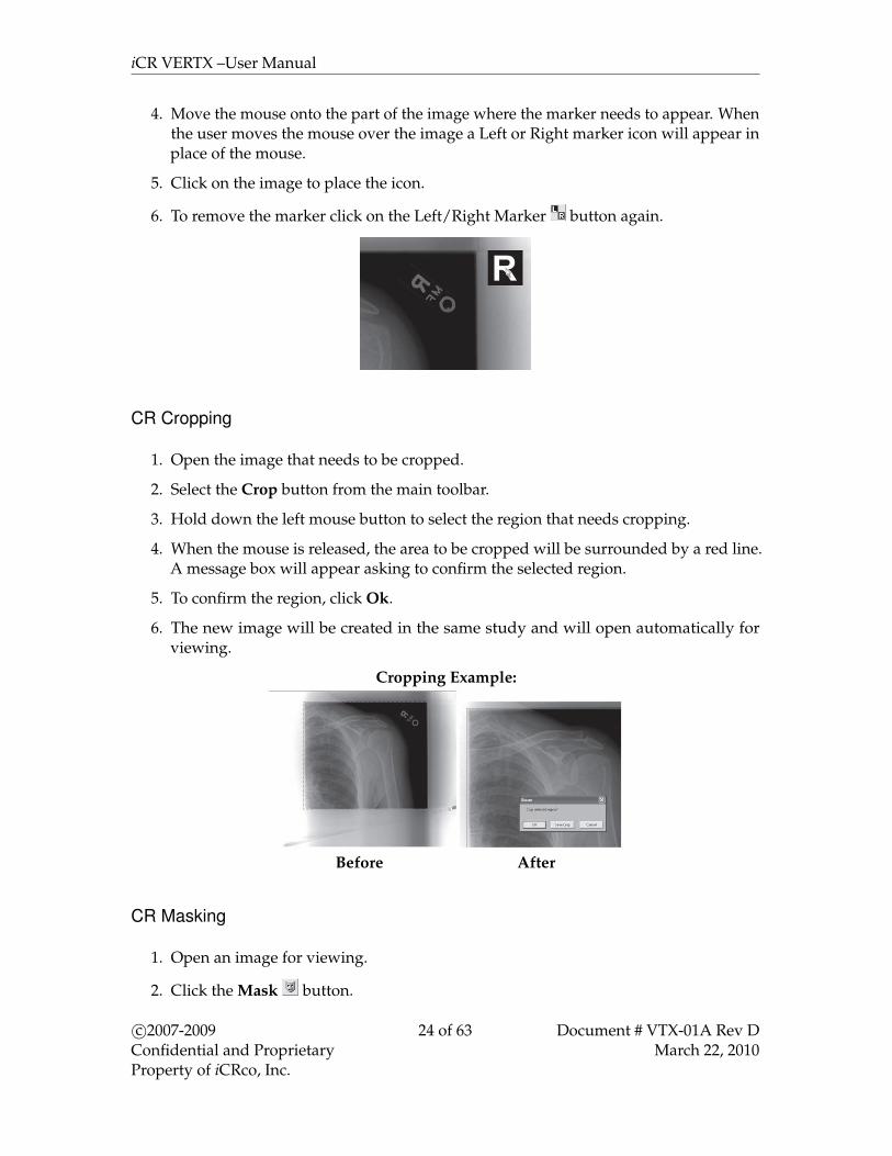
4. Move the mouse onto the part of the image where the marker needs to appear. Whenthe user moves the mouse over the image a Left or Right marker icon will appear inplace of the mouse.
5. Click on the image to place the icon.
6. To remove the marker click on the Left/Right Marker button again.
CR Cropping
1. Open the image that needs to be cropped.
2. Select the Crop button from the main toolbar.
3. Hold down the left mouse button to select the region that needs cropping.
4. When the mouse is released, the area to be cropped will be surrounded by a red line.A message box will appear asking to confirm the selected region.
5. To confirm the region, click Ok.
6. The new image will be created in the same study and will open automatically forviewing.
Cropping Example:
Before After
CR Masking
1. Open an image for viewing.
2. Click the Mask button.
c©2007-2009Confidential and ProprietaryProperty of iCRco, Inc.
24 of 63 Document # VTX-01A Rev DMarch 22, 2010

iCR VERTX –User Manual
3. To remove the collimation mask, select the Mask button again.
CR Masking Example
Before Masking After Masking
CR User Masking
1. Open an image for viewing.
2. Click the User Mask button.
3. Select the number of views from the Multi-View Mask dialog, (i.e., if there are two handexposures on one image, select the two-view button).
4. Hold the left mouse button down on the start region and move the mouse to the endof the mask region.
5. Repeat step 4 for each exposure. After the user has completed selecting the numberof exposures, the masks will appear on the image.
6. To remove the User Mask, select the User Mask button.
Moving Icon Thumbnails
1. Open a patient study for viewing.
2. Hold down the Ctrl key while clicking the left mouse button on the image that needsto be moved. The arrow icon will change to a hand icon . The icon highlighted in
c©2007-2009Confidential and ProprietaryProperty of iCRco, Inc.
25 of 63 Document # VTX-01A Rev DMarch 22, 2010

iCR VERTX –User Manual
red shows the location where the image will be dropped.
3. To drop the icon, simply release the left mouse button.
Note If the moving icon is highlighted, thisindicates that it will return to its original po-sition. If an icon is dragged forwards in posi-tion (i.e. the image number of the highlightedicon is higher than the moving icon) then allicons between its original position and its newposition will move backwards and each im-age number decreases by one. If an icon isdragged backwards in position (i.e. the imagenumber of the highlighted icon is less than themoving icon) then all icons between its orig-inal position and its new position will moveforward and each image number increases byone. If no icons are highlighted when drag-ging, then the image will be returned to itsoriginal position.
CR Processing
1. Open an image for viewing.
2. Select an anatomy from the CR Preset box.
3. Click the Process button to begin the processing.
4. The user may press the Reset button to restore the original image data set.Note the user can also press the Process button again and the original data set will
be automatically restored and processed again.
5. To optimize processing strength, change Gain and Frequency Enhancement as needed.Note The user can update the CR preset by selecting the Update button, which will
ensure that these processing strengths will be used each time with the currentlyselected anatomy.
CR Processing Example:
c©2007-2009Confidential and ProprietaryProperty of iCRco, Inc.
26 of 63 Document # VTX-01A Rev DMarch 22, 2010
iCR VERTX –User Manual
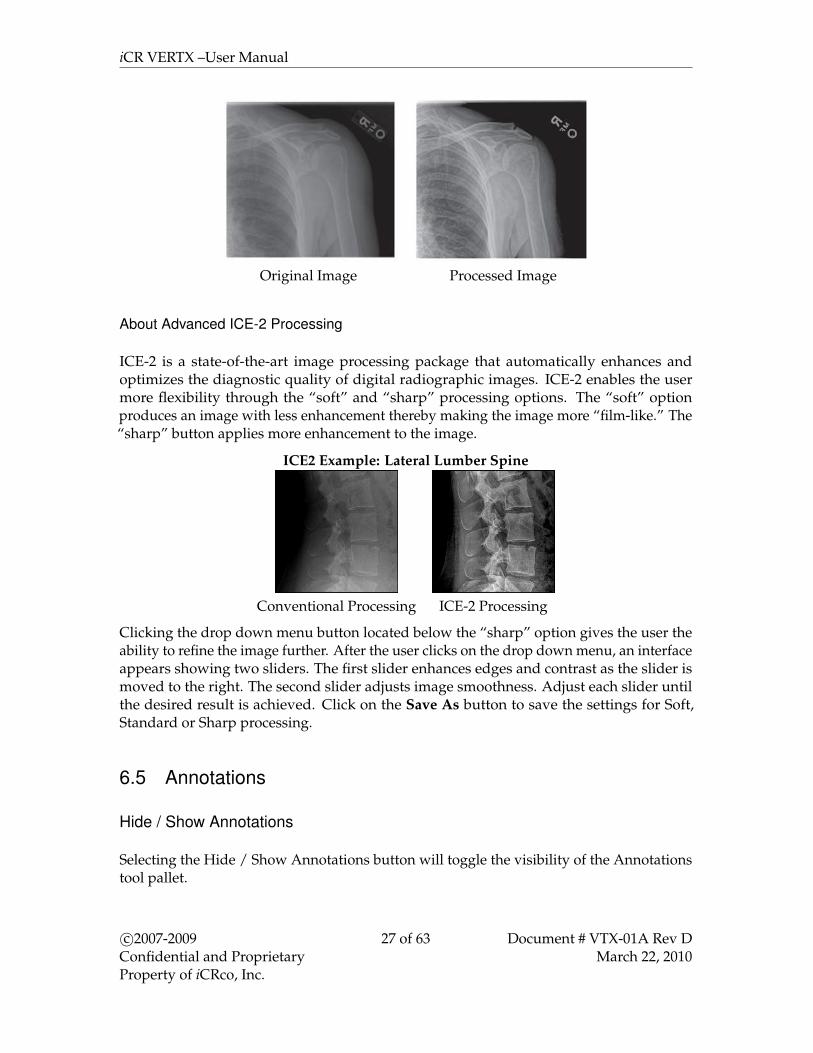
Original Image Processed Image
About Advanced ICE-2 Processing
ICE-2 is a state-of-the-art image processing package that automatically enhances andoptimizes the diagnostic quality of digital radiographic images. ICE-2 enables the usermore flexibility through the “soft” and “sharp” processing options. The “soft” optionproduces an image with less enhancement thereby making the image more “film-like.” The“sharp” button applies more enhancement to the image.
ICE2 Example: Lateral Lumber Spine
Conventional Processing ICE-2 Processing
Clicking the drop down menu button located below the “sharp” option gives the user theability to refine the image further. After the user clicks on the drop down menu, an interfaceappears showing two sliders. The first slider enhances edges and contrast as the slider ismoved to the right. The second slider adjusts image smoothness. Adjust each slider untilthe desired result is achieved. Click on the Save As button to save the settings for Soft,Standard or Sharp processing.
6.5 Annotations
Hide / Show Annotations
Selecting the Hide / Show Annotations button will toggle the visibility of the Annotationstool pallet.
c©2007-2009Confidential and ProprietaryProperty of iCRco, Inc.
27 of 63 Document # VTX-01A Rev DMarch 22, 2010

iCR VERTX –User Manual
Annotation Defaults
Used to change the default font name, font size and colors.Select the Defaults button on the annotations toolbar.
Embed Annotations in Image
Clicking on the Embed Annotations in Image button will save all the annotations into theimage, enabling the user to DICOM send images with annotations. If the annotations arenot embedded, they will not be sent with the image when doing a DICOM send.
Line Annotations
Creates a straight line on the image.
1. Select the Line button from the annotations toolbar.
2. Left mouse click on the area of the image to set the first endpoint.
3. Move the mouse to where the second endpoint will be.
4. Left mouse click on the are of the image to set the second endpoint.
Extended Line Annotation
Creates a straight line that passes through the image.
1. Select the Extended Line from the annotations toolbar.
2. Left mouse click on the area of the image to set the first endpoint.
Note The line will be extended through the entire image.
3. Move the mouse to where the second endpoint will be.
4. Left mouse click on the area of the image to set the second endpoint.
c©2007-2009Confidential and ProprietaryProperty of iCRco, Inc.
28 of 63 Document # VTX-01A Rev DMarch 22, 2010
iCR VERTX –User Manual
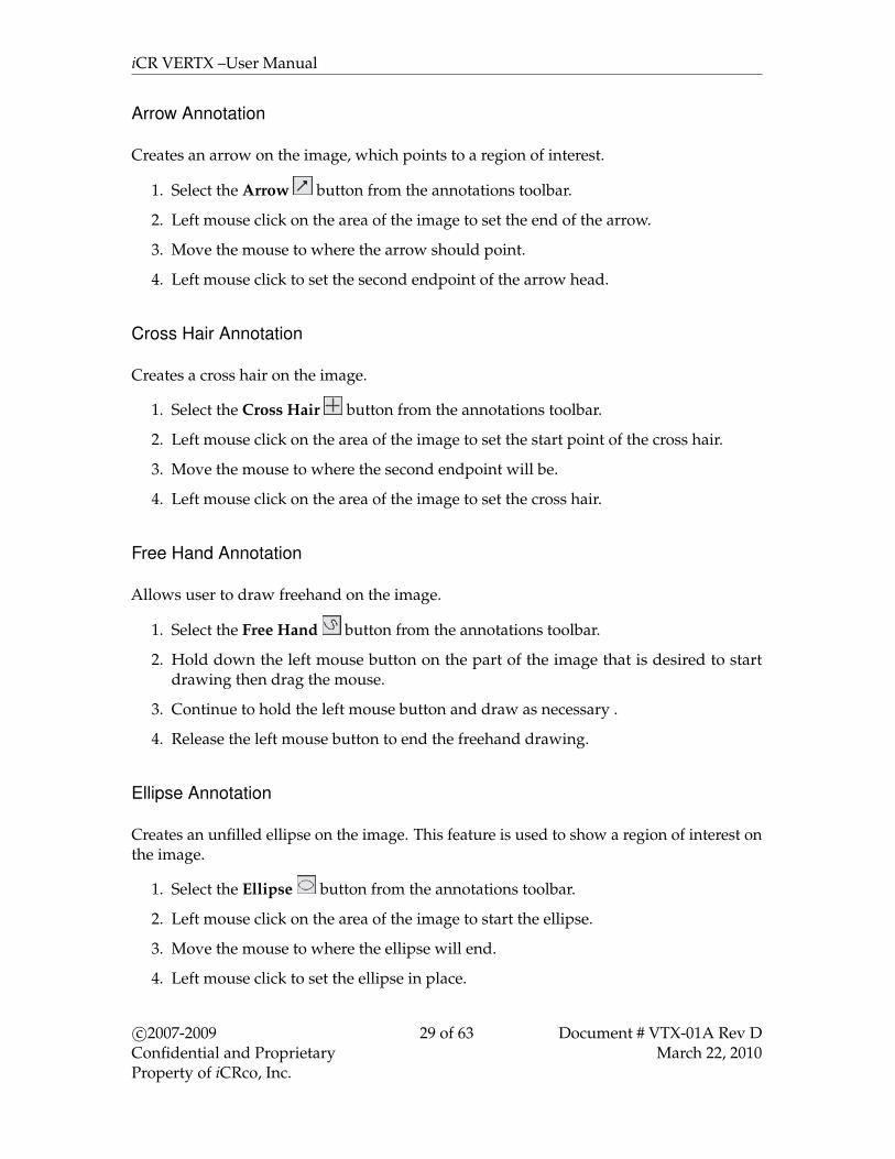
Arrow Annotation
Creates an arrow on the image, which points to a region of interest.
1. Select the Arrow button from the annotations toolbar.
2. Left mouse click on the area of the image to set the end of the arrow.
3. Move the mouse to where the arrow should point.
4. Left mouse click to set the second endpoint of the arrow head.
Cross Hair Annotation
Creates a cross hair on the image.
1. Select the Cross Hair button from the annotations toolbar.
2. Left mouse click on the area of the image to set the start point of the cross hair.
3. Move the mouse to where the second endpoint will be.
4. Left mouse click on the area of the image to set the cross hair.
Free Hand Annotation
Allows user to draw freehand on the image.
1. Select the Free Hand button from the annotations toolbar.
2. Hold down the left mouse button on the part of the image that is desired to startdrawing then drag the mouse.
3. Continue to hold the left mouse button and draw as necessary .
4. Release the left mouse button to end the freehand drawing.
Ellipse Annotation
Creates an unfilled ellipse on the image. This feature is used to show a region of interest onthe image.
1. Select the Ellipse button from the annotations toolbar.
2. Left mouse click on the area of the image to start the ellipse.
3. Move the mouse to where the ellipse will end.
4. Left mouse click to set the ellipse in place.
c©2007-2009Confidential and ProprietaryProperty of iCRco, Inc.
29 of 63 Document # VTX-01A Rev DMarch 22, 2010

iCR VERTX –User Manual
Rectangle Annotation
Creates an unfilled box on the image. Used to show a region of interest on the image.
1. Select the Box button from the annotations toolbar.
2. Left mouse click on the area of the image to start the box.
3. Move the mouse to where the box will end.
4. Left mouse click to set the box in place.
Text Annotation
Creates a text annotation on the image.
1. Select the Text button from the annotations toolbar.
2. Left mouse click on the area of the image to set the upper left corner of the text box.
3. Move the mouse to where the text box will end.
4. Left mouse click to set the size of the text box.
5. The text box will become white with a flashing cursor. Type text.
6. Click anywhere on the image to end the text box.
Measurement Annotation
Used to measure the distance of a straight line on the image. This can be in inches, cm, mmand pixels.
1. Select the Measurement button from the annotations toolbar.
2. Left mouse click on the image to set the first endpoint of the measurement.
3. Move the mouse to where the endpoint of the measurement will be.
4. Left mouse click to set the endpoint of the measurement. The measurement willappear below the line.
5. To place the text in this default position left mouse click on the same point again. Tomove the text out of the way, move the mouse to the desired location and left mouseclick to set the placement of the text.
c©2007-2009Confidential and ProprietaryProperty of iCRco, Inc.
30 of 63 Document # VTX-01A Rev DMarch 22, 2010

iCR VERTX –User Manual
Calibration
The calibration tool compensates for image magnification. It will allow the user to take anobject of known length (a coin, ruler, etc that is not susceptible to measurement distortion),draw a linear measurement, and assign a length value such that measurements made withother tools will be accurate in the unit of measurement.
Angle Measurement Annotation
Used to draw an angle on the image.
1. Select the Angle Measurement button on the annotations toolbar.
2. Left mouse click on the image to set the vertex (center point) of the angle.
3. Move the mouse to where the endpoint of the first vector will be.
4. Left mouse click to set the endpoint of the first vector.
5. Move the mouse to where the endpoint of the second vector will be.
6. Left mouse click to set the endpoint of the second vector. The angle measurementwill appear.
7. To place the angle text in this default position left mouse click on the same pointagain. To move the angle text out of the way or to change angles, move the mouse tothe desired location and left mouse click to set the placement.
Cobb Angle Annotation
Used to draw a cobb angle on the image.
1. Select the Cobb Angle button on the annotations toolbar.
2. Left mouse click on the area of the image to set the first endpoint of the first line.
3. Move the mouse to where the second endpoint of the first line will be.
4. Left mouse click on the area of the image to set the second endpoint of the first line.
5. Left mouse click on the area of the image to set the first endpoint of the second line.
6. Move the mouse to where the second endpoint of the second line will be.
7. Left mouse click on the area of the image to set the second endpoint of the secondline. The angle measurement will appear.
8. To place the angle text in this default position left mouse click on the same pointagain. To move the angle text out of the way, move the mouse to the desired locationand left mouse click to set the placement.
c©2007-2009Confidential and ProprietaryProperty of iCRco, Inc.
31 of 63 Document # VTX-01A Rev DMarch 22, 2010

iCR VERTX –User Manual
Heart to Lung Ratio Annotation
Used to find the heart to lung ratio.
1. Select the Heart to Lung Ratio button on the annotations toolbar.
2. Left mouse click on the area of the image to set the first endpoint of the first line.
3. Move the mouse to where the second endpoint of the first line will be.
4. Left mouse click on the area of the image to set the second endpoint of the first line.
5. Left mouse click on the area of the image to set the first endpoint of the second line.
6. Move the mouse to where the second endpoint of the second line will be.
7. Left mouse click on the area of the image to set the second endpoint of the secondline. The ratio measurement will appear.
Center Line Annotation
Used to find the center line of four points.
1. Select the Center Line button on the annotations toolbar.
2. Left mouse click on the area of the image to set the first point.
3. Left mouse click on the area of the image to set the second point
4. Left mouse click on the area of the image to set the third point.
5. Left mouse click on the area of the image to set the fourth point. The center line ofthese four points will be drawn on the image.
Center Point
Used to find the center between two user settable points.
1. Select the Center Point button on the annotations toolbar.
2. Left mouse click on an area to set the first point (it will appear as an X).
3. Left mouse click on an area to set the second point (it will appear as an X).
4. A third, large X will appear in the center of the two other Xs.
c©2007-2009Confidential and ProprietaryProperty of iCRco, Inc.
32 of 63 Document # VTX-01A Rev DMarch 22, 2010
iCR VERTX –User Manual
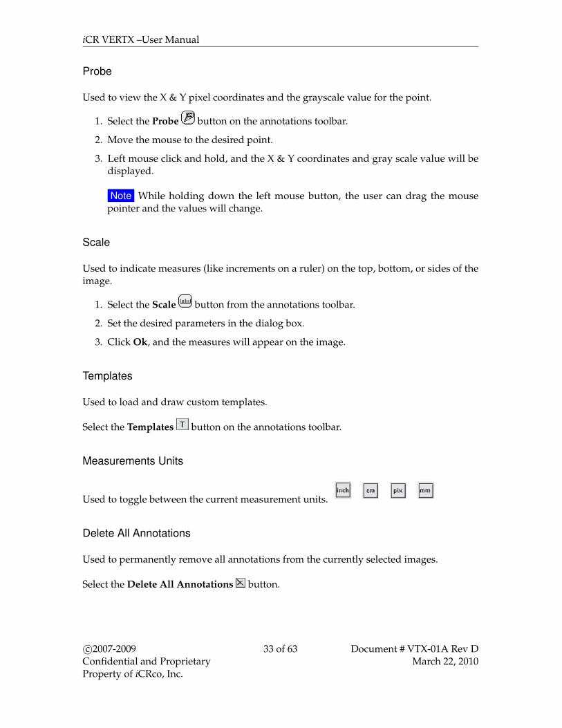
Probe
Used to view the X & Y pixel coordinates and the grayscale value for the point.
1. Select the Probe button on the annotations toolbar.
2. Move the mouse to the desired point.
3. Left mouse click and hold, and the X & Y coordinates and gray scale value will bedisplayed.
Note While holding down the left mouse button, the user can drag the mousepointer and the values will change.
Scale
Used to indicate measures (like increments on a ruler) on the top, bottom, or sides of theimage.
1. Select the Scale button from the annotations toolbar.
2. Set the desired parameters in the dialog box.
3. Click Ok, and the measures will appear on the image.
Templates
Used to load and draw custom templates.
Select the Templates button on the annotations toolbar.
Measurements Units
Used to toggle between the current measurement units.
Delete All Annotations
Used to permanently remove all annotations from the currently selected images.
Select the Delete All Annotations button.
c©2007-2009Confidential and ProprietaryProperty of iCRco, Inc.
33 of 63 Document # VTX-01A Rev DMarch 22, 2010

iCR VERTX –User Manual
Deleting Annotations Individually
1. Select the annotation.
2. Right mouse click on the annotation.
3. Select Delete from the pop-up menu.
Selecting Annotations
1. Move the mouse over the annotation. The mouse pointer will become a pointinghand.
2. Left mouse click on the annotation to select it. The annotation will become a dottedline with several handles.
Moving Annotations
1. Select the annotation.
2. Move the mouse over the annotation onto any part of it except the handles (i.e. smallboxes). The icon will change to the moving annotations icon.
3. Left mouse click on the annotations and drag it anywhere on the image.
Resizing Annotations
1. Select the annotation.
2. Move the mouse over the annotation (onto any of the handles). The icon will changeto the resizing annotations icon.
3. Left mouse click on the annotation handle and drag it anywhere on the image.
c©2007-2009Confidential and ProprietaryProperty of iCRco, Inc.
34 of 63 Document # VTX-01A Rev DMarch 22, 2010

iCR VERTX –User Manual
Note For measurement annotations the size/angle will change accordingly. One of thehandles provided for measurement annotations will also allow the user to reposition thetext.
6.6 Patient CD/DVD Creator
Note CD/DVD Creation Software is NOT part of the QPC XSCAN32 Software. This sectionis optional for users who already have CD/DVD Creation Software already installed ontheir respective PCs.
1. In the patient information window select the patient(s) to be placed on the CD/DVD.To select multiple patients hold down your Ctrl key on the keyboard and using yourleft mouse button select each patient.
2. Click on the Create CD button in the toolbar. Selected patients will be copied into thepatient CD layout folder (C:\ XscanCDFolder).
Note If this is the first time using the patient CD creator feature a prompt will appearindicating the user to browse for the location of the DVD/CD Creator software.Alternatively, if Nero software is already installed on the PC, select the option UseNero scripting to create CD/DVD.
c©2007-2009Confidential and ProprietaryProperty of iCRco, Inc.
35 of 63 Document # VTX-01A Rev DMarch 22, 2010
iCR VERTX –User Manual
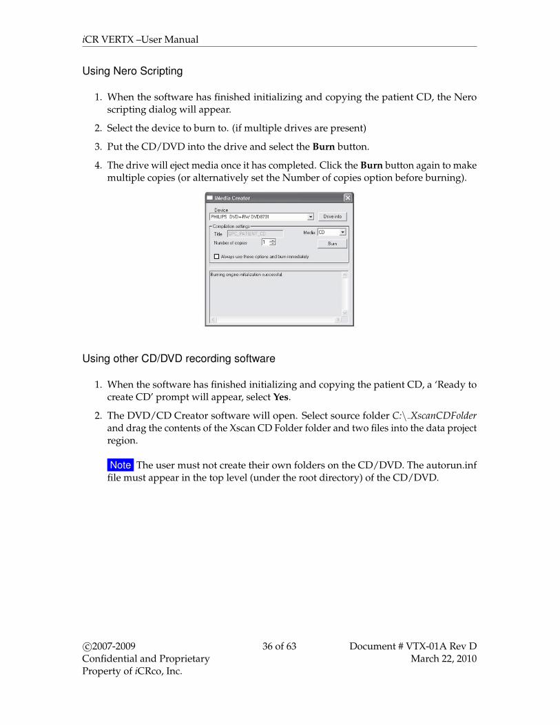
Using Nero Scripting
1. When the software has finished initializing and copying the patient CD, the Neroscripting dialog will appear.
2. Select the device to burn to. (if multiple drives are present)
3. Put the CD/DVD into the drive and select the Burn button.
4. The drive will eject media once it has completed. Click the Burn button again to makemultiple copies (or alternatively set the Number of copies option before burning).
Using other CD/DVD recording software
1. When the software has finished initializing and copying the patient CD, a ‘Ready tocreate CD’ prompt will appear, select Yes.
2. The DVD/CD Creator software will open. Select source folder C:\ XscanCDFolderand drag the contents of the Xscan CD Folder folder and two files into the data projectregion.
Note The user must not create their own folders on the CD/DVD. The autorun.inffile must appear in the top level (under the root directory) of the CD/DVD.
c©2007-2009Confidential and ProprietaryProperty of iCRco, Inc.
36 of 63 Document # VTX-01A Rev DMarch 22, 2010

iCR VERTX –User Manual
3. Click the Record button in CD Creator software.
6.7 Associating a Barcode with a Study
1. In the patient information window, enter patient and study information.
2. Select patient and study.
3. Select Add Barcode button.
4. Using a barcode reader, scan the barcode of an unexposed cassette.
5. The barcode will be added into the barcode list with the default cassette size 14x17.
6. Repeat steps 3 to 5 for each cassette that will be associated with the study.
c©2007-2009Confidential and ProprietaryProperty of iCRco, Inc.
37 of 63 Document # VTX-01A Rev DMarch 22, 2010

iCR VERTX –User Manual
Note The user can change the cassette size by clicking under the column Cassette Size andselecting the actual size. This will be saved for future use in the database.
Note The user can remove the association by selecting the barcode from the list andselecting the Delete Barcode button.
6.8 Finding Barcodes and Scanning Images
1. In the patient information window, select the Find Barcode Edit box.
2. Using a barcode reader, scan the barcode of the exposed cassette.
3. Select the anatomy information for the study.Note This can be corrected later in QPC XSCAN32 when viewing the images.
4. Load cassette into the CR unit.
5. Select the appropriate scan button.
6. QPC XSCAN32 will automatically open the study that the cassette is associated with.The scan interface will open with the details of the associated patient.
7. The image will be imported into QPC XSCAN32 when it has completed scanning.The association with that cassette barcode and the study will be removed and thecassette can be reassigned to another patient.
c©2007-2009Confidential and ProprietaryProperty of iCRco, Inc.
38 of 63 Document # VTX-01A Rev DMarch 22, 2010

iCR VERTX –User Manual
Other Tips
The scan interface also allows the user to find barcodes in the database. The patientinformation displayed in the scan interface will change depending on the barcode selectedfor scanning.
The image below indicates that the image will appear under the patient Joe Smith and thebarcode for the cassette that will be scanned is 01003.
There is an option in the scan interface settings that requires the user to scan the barcodebefore they are able to scan cassettes into the interface. In other words they have to tellthe scan interface which barcode they are scanning. If no barcode has been selected forscanning the user will be prompted to find a barcode.
6.9 Archiving QPC XSCAN32 Database
1. Open XSCAN.
2. Go to File→ Archive Database.
3. The user is asked to confirm the archive process, click Yes.
4. Select the location to archive the database to.
c©2007-2009Confidential and ProprietaryProperty of iCRco, Inc.
39 of 63 Document # VTX-01A Rev DMarch 22, 2010

iCR VERTX –User Manual
5. When archiving is completed a message will appear informing the user of the archivelocation.Note the current date and time is used for the folder name of the archived database.
6.10 Restoring Archived Database
! WARNING It is strongly recommended to backing up data to non-spinning mediaCD/DVD or an archive (PACS) with RAID capability to ensure no loss of data.
1. To restore an Archive, go to File→ Restore Archive.
Note The current database in QPC must be empty.
2. Select the location of the database to restore.
6.11 Searching QPC XSCAN32 Archive
1. Go to File→ Search Archives.
c©2007-2009Confidential and ProprietaryProperty of iCRco, Inc.
40 of 63 Document # VTX-01A Rev DMarch 22, 2010
iCR VERTX –User Manual
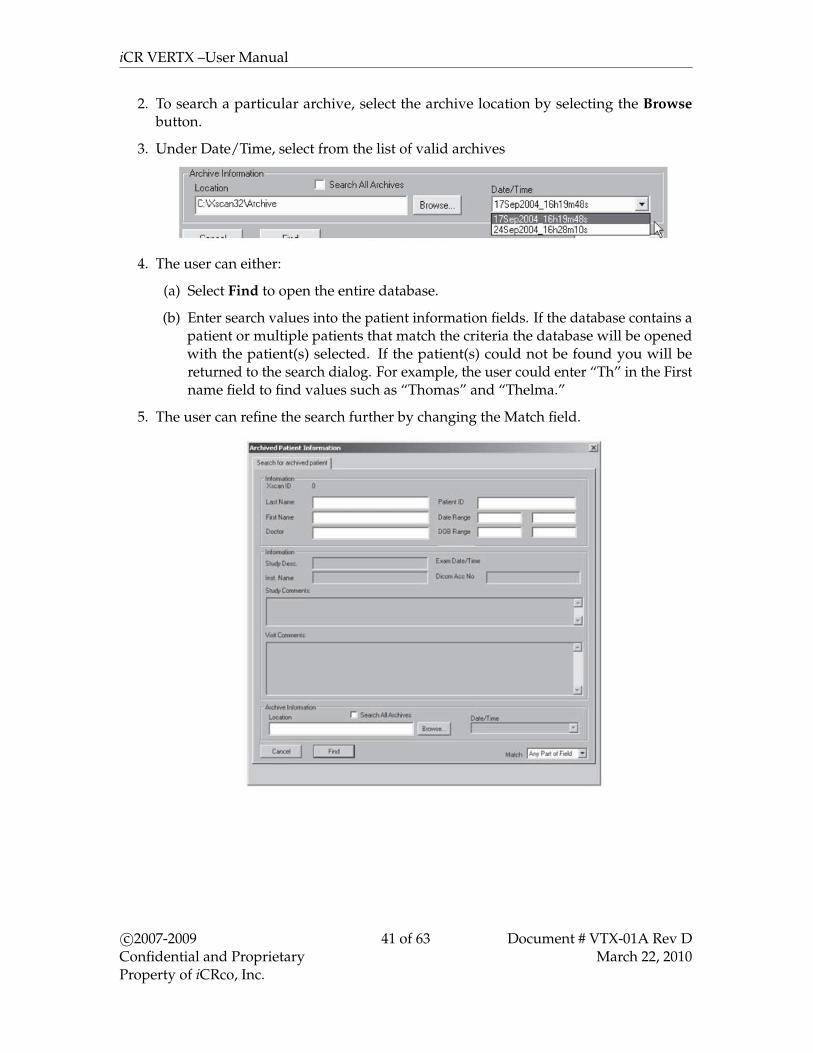
2. To search a particular archive, select the archive location by selecting the Browsebutton.
3. Under Date/Time, select from the list of valid archives
4. The user can either:
(a) Select Find to open the entire database.
(b) Enter search values into the patient information fields. If the database contains apatient or multiple patients that match the criteria the database will be openedwith the patient(s) selected. If the patient(s) could not be found you will bereturned to the search dialog. For example, the user could enter “Th” in the Firstname field to find values such as “Thomas” and “Thelma.”
5. The user can refine the search further by changing the Match field.
c©2007-2009Confidential and ProprietaryProperty of iCRco, Inc.
41 of 63 Document # VTX-01A Rev DMarch 22, 2010
iCR VERTX –User Manual
6.12 Modality Work List Query
6.12.1 Setting-up Modality Work List Query
1. Open QPC XSCAN32, then go to Options→ Preferences→ Image Transfer tab.
2. Check the box for Use DICOM Modality Work List Query.
3. Click the Apply button, then click the Ok button.
4. The QPC XSCAN32 Modality Work List Query window will appear.
Setting-up DICOM Modality Work List Query
Note The EMR/RIS/HIS must support DICOM Modality Work List Query.
1. In the XSCAN32 Modality Work List Query window, click the Options button.
2. Select the radio dialog check box for DICOM Query
Note The User may also set the auto-query options in the Options dialog.
3. Click the Ok button.
4. In the XSCAN32 Modality Work List Query window, click the Select Target button.
5. In the Image Targets window, highlight the desired target, then click the Ok button.
Setting-up Work List HL7 Listen
Note The EMR/RIS/HIS must be able to send HL7 messages. It is not enough just togeneral the HL7 message.
1. In the XSCAN32 Modality Work List Query window, click the Options button.
2. Select the radio dialog check box for HL7 Listen.
3. Click the Ok button.
4. An HL7 Listen application will open.
5. Configure the EMR/HIS/RIS to send its HL7 messages to the IP address of thecomputer running QPC XSCAN32 on port 6000.
Setting-up Work List Text File Listen
Note The EMR/RIS/HIS must be able to format and send a plain text message.
c©2007-2009Confidential and ProprietaryProperty of iCRco, Inc.
42 of 63 Document # VTX-01A Rev DMarch 22, 2010

iCR VERTX –User Manual
Note The Text File Listener should only be used if the EMR/RIS/HIS does not supportDICOM Modality Work List Query or HL7 Messaging.
1. In the XSCAN32 Modality Work List Query window, click the Options button.
2. Select the radio dialog check box for Text File.
3. Instruct your EMR/RIS/HIS vendor to contact iCRco Tech Support to obtain the textfile format.
6.12.2 Using Modality Work List Query
1. To activate the Modality Work List Query interface click on the Work List Querybutton in the Patient Information window.
2. The QPC XSCAN32 Modality Work List Query dialog will open. Click on QueryWork List button to query the HIS/RIS system.
(a) Query Work List Button
(b) Search fields. For example, to search for all patients with the last name Smith,select the Last Name field in the search box and type Smith and then click enter.Only the patients that have a last name of Smith will appear.
(c) The user can also specify query options such as:
• querying automatically when work list query dialog is opened.
• query on a timer (i.e. every 5 minutes)
• query by modality (i.e. CR patients only)
c©2007-2009Confidential and ProprietaryProperty of iCRco, Inc.
43 of 63 Document # VTX-01A Rev DMarch 22, 2010
iCR VERTX –User Manual
• query by AET
• query by Date (i.e. today’s date only)
(d) Click here to select the target to query.Note The user will only need to do this once.
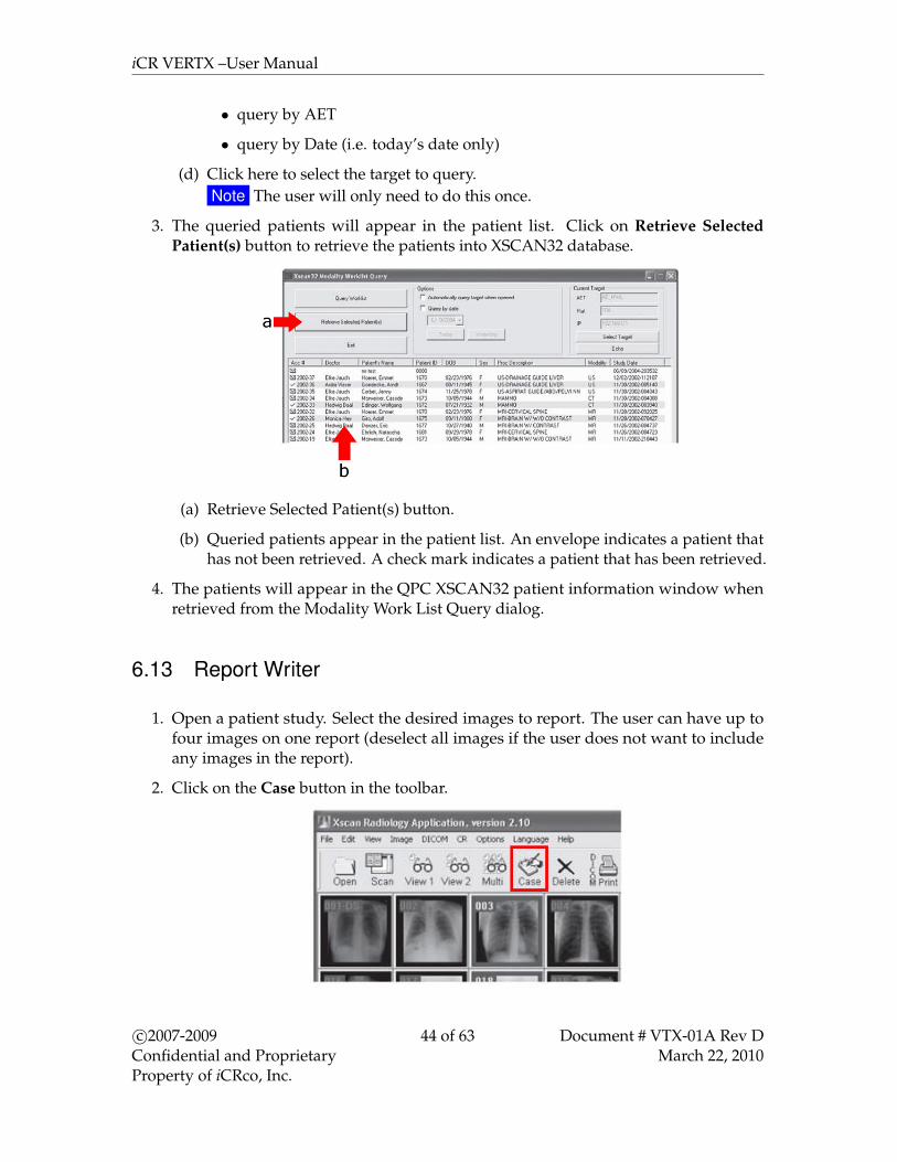
3. The queried patients will appear in the patient list. Click on Retrieve SelectedPatient(s) button to retrieve the patients into XSCAN32 database.
(a) Retrieve Selected Patient(s) button.
(b) Queried patients appear in the patient list. An envelope indicates a patient thathas not been retrieved. A check mark indicates a patient that has been retrieved.
4. The patients will appear in the QPC XSCAN32 patient information window whenretrieved from the Modality Work List Query dialog.
6.13 Report Writer
1. Open a patient study. Select the desired images to report. The user can have up tofour images on one report (deselect all images if the user does not want to includeany images in the report).
2. Click on the Case button in the toolbar.
c©2007-2009Confidential and ProprietaryProperty of iCRco, Inc.
44 of 63 Document # VTX-01A Rev DMarch 22, 2010
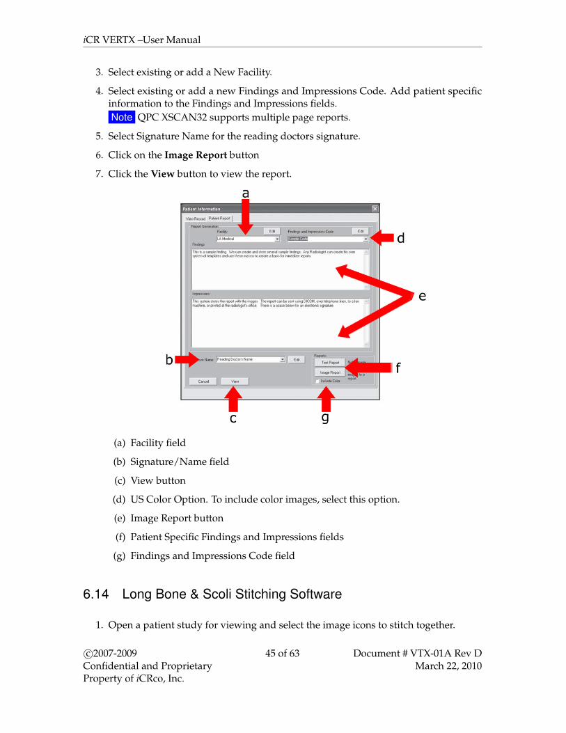
iCR VERTX –User Manual
3. Select existing or add a New Facility.
4. Select existing or add a new Findings and Impressions Code. Add patient specificinformation to the Findings and Impressions fields.Note QPC XSCAN32 supports multiple page reports.
5. Select Signature Name for the reading doctors signature.
6. Click on the Image Report button
7. Click the View button to view the report.
(a) Facility field
(b) Signature/Name field
(c) View button
(d) US Color Option. To include color images, select this option.
(e) Image Report button
(f) Patient Specific Findings and Impressions fields
(g) Findings and Impressions Code field
6.14 Long Bone & Scoli Stitching Software
1. Open a patient study for viewing and select the image icons to stitch together.
c©2007-2009Confidential and ProprietaryProperty of iCRco, Inc.
45 of 63 Document # VTX-01A Rev DMarch 22, 2010

iCR VERTX –User Manual
2. Click on the Stitch button in the toolbar.Note This will only appear in the toolbar when the user has installed the stitching
module software.
3. Organize the images in the correct viewing order. Note that no matter what theusers selects for orientation (horizontal or vertical) that the software will only stitchvertically. For example, if the images appear as they do in Figure 1, then click theSwap Images button. If the images appear as they do in Figure 2, then rotate theimages to the right 90◦.
Figure 1 Figure 2
4. Select the Start Stitching button when the images are positioned correctly. WhenXSCAN finishes stitching, it will display a message box stating that the image is readyfor viewing and the new image will automatically be imported to the study.
Stitching Tips:
1. Images must have at least 1 inch of overlapping data
c©2007-2009Confidential and ProprietaryProperty of iCRco, Inc.
46 of 63 Document # VTX-01A Rev DMarch 22, 2010

iCR VERTX –User Manual
CORRECT. INCORRECT.Overlapping data appears The two edges to be stitched
in both images. should not be collimated.
2. It is important not to collimate on the edges that will be stitched together.Note The user can collimate on any other edges.
3. Do not move the angle of the anatomy between x-rays. For example, if two images ofan arm are taken on two different cassettes, do not move the angle of the arm for thesecond x-ray.
4. Do not change the resolution between x-rays. (All images must be the same scanresolution.)
6.15 Setting Up DICOM Send
1. Open QPC XSCAN32.
2. Open DICOM Controller V1.00.Note If the user doesn’t have the window in the task bar open, go to Options →
Preferences→ Image Transfer Tab→ Use DICOM to transfer images.
c©2007-2009Confidential and ProprietaryProperty of iCRco, Inc.
47 of 63 Document # VTX-01A Rev DMarch 22, 2010

iCR VERTX –User Manual
3. Click on Targets button and the Image Targets dialog will appear.
6.16 DICOM Send
1. Open a patient study for viewing and select the image icons to send.
2. Click on the DICOM Send button in the toolbar.Note This will only appear in the toolbar when the Use DICOM to transfer images
option is selected in the Image Transfer preferences tab.
3. The Image Targets dialog will appear. Select the target(s) to send the selected imagesto.
4. Select OK to confirm the selected target(s).
c©2007-2009Confidential and ProprietaryProperty of iCRco, Inc.
48 of 63 Document # VTX-01A Rev DMarch 22, 2010

iCR VERTX –User Manual
5. The status of the send will appear in the Event Log of the DICOM Controller window.Note If sending to another XSCAN32 application the user can turn compression on
and select a compression type (low, medium, high).
6.17 DICOM Retrieve
1. Open QPC XSCAN32
2. Click on the DICOM Retrieve button in the toolbar.Note This will only appear in the toolbar when the user has the Use DICOM to
transfer images option selected in the Image Transfer preferences tab.
3. The Image Targets dialog will appear. Select the target to retrieve images from.
4. Select OK to confirm the selected target.
5. If the user has selected the Search Parameters option, then enter any relevant patient
c©2007-2009Confidential and ProprietaryProperty of iCRco, Inc.
49 of 63 Document # VTX-01A Rev DMarch 22, 2010

iCR VERTX –User Manual
or study information. For example, to search on all patients with the name JohnSmith, type John Smith into the Patient Name field. To search on all patients withthe last name Smith, type *Smith* into the Patient Name field. Where the asterisk * isused as a wildcard. To search on Study ID 12345, type 12345 into the Study ID field or1234* to bring up all study ID’s starting with 1234.Note It is not necessary to fill out all fields. For a description of the valid wildcards
click on the Wildcards button.
6. The list of matching patients will be returned.
7. Select the patient(s) to retrieve from the list and click on the Retrieve button.
6.18 DICOM Auto-Send
6.18.1 Setting-up DICOM Auto-Send
1. Open QPC XSCAN32.
c©2007-2009Confidential and ProprietaryProperty of iCRco, Inc.
50 of 63 Document # VTX-01A Rev DMarch 22, 2010
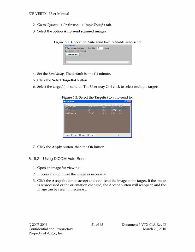
iCR VERTX –User Manual
2. Go to Options→ Preferences→ Image Transfer tab.
3. Select the option Auto send scanned images.
Figure 6.1: Check the Auto send box to enable auto-send
4. Set the Send delay. The default is one (1) minute.
5. Click the Select Target(s) button.
6. Select the target(s) to send to. The User may Ctrl-click to select multiple targets.
Figure 6.2: Select the Target(s) to auto-send to.
7. Click the Apply button, then the Ok button.
6.18.2 Using DICOM Auto-Send
1. Open an image for viewing.
2. Process and optimize the image as necessary.
3. Click the Accept button to accept and auto-send the image to the target. If the imageis reprocessed or the orientation changed, the Accept button will reappear, and theimage can be resent if necessary.
c©2007-2009Confidential and ProprietaryProperty of iCRco, Inc.
51 of 63 Document # VTX-01A Rev DMarch 22, 2010
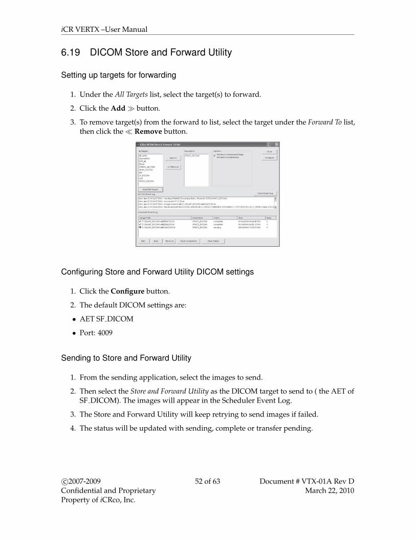
iCR VERTX –User Manual
6.19 DICOM Store and Forward Utility
Setting up targets for forwarding
1. Under the All Targets list, select the target(s) to forward.
2. Click the Add� button.
3. To remove target(s) from the forward to list, select the target under the Forward To list,then click the� Remove button.
Configuring Store and Forward Utility DICOM settings
1. Click the Configure button.
2. The default DICOM settings are:
• AET SF DICOM
• Port: 4009
Sending to Store and Forward Utility
1. From the sending application, select the images to send.
2. Then select the Store and Forward Utility as the DICOM target to send to ( the AET ofSF DICOM). The images will appear in the Scheduler Event Log.
3. The Store and Forward Utility will keep retrying to send images if failed.
4. The status will be updated with sending, complete or transfer pending.
c©2007-2009Confidential and ProprietaryProperty of iCRco, Inc.
52 of 63 Document # VTX-01A Rev DMarch 22, 2010
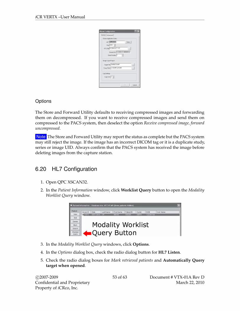
iCR VERTX –User Manual
Options
The Store and Forward Utility defaults to receiving compressed images and forwardingthem on decompressed. If you want to receive compressed images and send them oncompressed to the PACS system, then deselect the option Receive compressed image, forwarduncompressed.
Note The Store and Forward Utility may report the status as complete but the PACS systemmay still reject the image. If the image has an incorrect DICOM tag or it is a duplicate study,series or image UID. Always confirm that the PACS system has received the image beforedeleting images from the capture station.
6.20 HL7 Configuration
1. Open QPC XSCAN32.
2. In the Patient Information window, click Worklist Query button to open the ModalityWorklist Query window.
3. In the Modality Worklist Query windows, click Options.
4. In the Options dialog box, check the radio dialog button for HL7 Listen.
5. Check the radio dialog boxes for Mark retrieved patients and Automatically Querytarget when opened.
c©2007-2009Confidential and ProprietaryProperty of iCRco, Inc.
53 of 63 Document # VTX-01A Rev DMarch 22, 2010
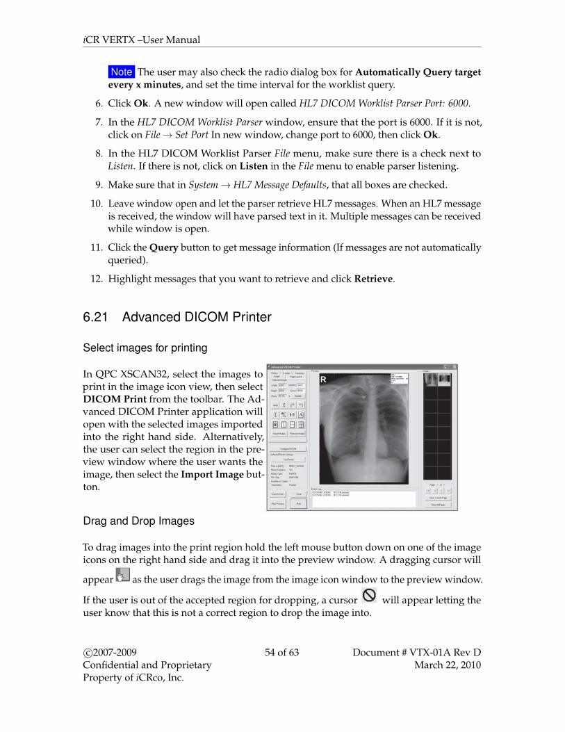
iCR VERTX –User Manual
Note The user may also check the radio dialog box for Automatically Query targetevery x minutes, and set the time interval for the worklist query.
6. Click Ok. A new window will open called HL7 DICOM Worklist Parser Port: 6000.
7. In the HL7 DICOM Worklist Parser window, ensure that the port is 6000. If it is not,click on File→ Set Port In new window, change port to 6000, then click Ok.
8. In the HL7 DICOM Worklist Parser File menu, make sure there is a check next toListen. If there is not, click on Listen in the File menu to enable parser listening.
9. Make sure that in System→ HL7 Message Defaults, that all boxes are checked.
10. Leave window open and let the parser retrieve HL7 messages. When an HL7 messageis received, the window will have parsed text in it. Multiple messages can be receivedwhile window is open.
11. Click the Query button to get message information (If messages are not automaticallyqueried).
12. Highlight messages that you want to retrieve and click Retrieve.
6.21 Advanced DICOM Printer
Select images for printing
In QPC XSCAN32, select the images toprint in the image icon view, then selectDICOM Print from the toolbar. The Ad-vanced DICOM Printer application willopen with the selected images importedinto the right hand side. Alternatively,the user can select the region in the pre-view window where the user wants theimage, then select the Import Image but-ton.
Drag and Drop Images
To drag images into the print region hold the left mouse button down on one of the imageicons on the right hand side and drag it into the preview window. A dragging cursor will
appear as the user drags the image from the image icon window to the preview window.
If the user is out of the accepted region for dropping, a cursor will appear letting theuser know that this is not a correct region to drop the image into.
c©2007-2009Confidential and ProprietaryProperty of iCRco, Inc.
54 of 63 Document # VTX-01A Rev DMarch 22, 2010
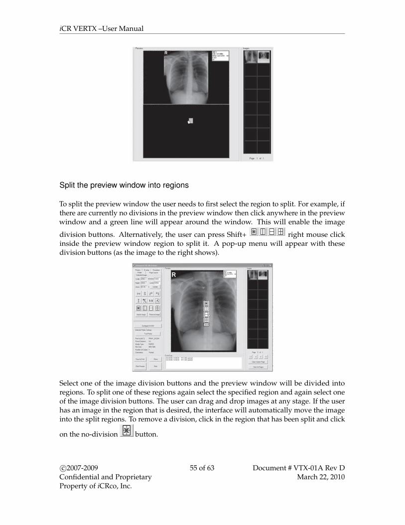
iCR VERTX –User Manual
Split the preview window into regions
To split the preview window the user needs to first select the region to split. For example, ifthere are currently no divisions in the preview window then click anywhere in the previewwindow and a green line will appear around the window. This will enable the image
division buttons. Alternatively, the user can press Shift+ right mouse clickinside the preview window region to split it. A pop-up menu will appear with thesedivision buttons (as the image to the right shows).
Select one of the image division buttons and the preview window will be divided intoregions. To split one of these regions again select the specified region and again select oneof the image division buttons. The user can drag and drop images at any stage. If the userhas an image in the region that is desired, the interface will automatically move the imageinto the split regions. To remove a division, click in the region that has been split and click
on the no-division button.
c©2007-2009Confidential and ProprietaryProperty of iCRco, Inc.
55 of 63 Document # VTX-01A Rev DMarch 22, 2010

iCR VERTX –User Manual
The user can show and hide the image divisions by clicking on the Page Layout tab, thenclick Show and Lock under Image Divisions. The user can view the current print settingsby looking at the left hand side of the Advanced DICOM Printer dialog. To change thesesettings, or to view more settings, click on the Printers tab.
Manipulating Images in the Preview Window
The Advanced DICOM Printer allows the user toflip, rotate, zoom, pan, invert and window/levelimages. To manipulate the images select the im-age in the preview window (the selection willbe shown by the green box surrounding the im-age).
The user can flip, rotate and invert by using the but-tons on the left hand side of the DICOM Printer dia-log.
The user can zoom by using the right mouse buttonon the selected image.
To pan the image use the left mouse button on the selected image.Note The user can only pan the image when it is zoomed in. To window/level the user
can either use the middle scroll button on the mouse or type the required window/level
c©2007-2009Confidential and ProprietaryProperty of iCRco, Inc.
56 of 63 Document # VTX-01A Rev DMarch 22, 2010

iCR VERTX –User Manual
into the edit boxes on the left hand side of the Advanced DICOM Printer dialog. Then pressthe Update button to change the window/level for the image.
The user can also press the 1:1 button to tell the Advanced DICOM Printer dialog to printimages at 1:1 resolution.
The user can use the Orientation button to change from landscape to portrait view.
Change margins
The margin tab permits the user to specify, in English or metric units, the size of the borderson the printed image. The top and bottom borders on the page can be adjusted indepen-dently of the borders for the left and the right hand side of the page.
Additionally, the user has the option to control the internalmargins, which define the amount of space left between in-dividual frames on a page with multiple images. Internalmargins are defined as multiples of the print page bordersize.
By default, internal margins are the same size as the bor-ders, with image margins on, the left and right hand sideof each frame are equal to the left and right hand bor-ders. Margins on the top and bottom of each frameare equal to the top and bottom borders of the printedpage.
If the user intends to cut individual frames out of the printedpage, it is recommended that internal margins are set to twicethat of the page, which will give a uniform border size on the individual image segments.If it is necessary to maximize the amount of space on the printed page, the internal marginscan be turned off altogether.
Saving and Loading Print Layout
The Templates tab allows the user to save and load pre-defined print layouts. There are fiveuser defined layouts. Set up the layout on the preview window and then select one of thebuttons labeled Click here to save current layout! The user will be prompted for a title.
To save more layouts click on the Save Current Template button. here the user can set afile name for the Layout. The default save location is C : \XScan32\Layout\Custom.
c©2007-2009Confidential and ProprietaryProperty of iCRco, Inc.
57 of 63 Document # VTX-01A Rev DMarch 22, 2010

iCR VERTX –User Manual
Adding patient demographics
Select the Overlay tab to bring up the patient demographic layout options.From here the user can select:
• Text position (includes top left, top center, top right, bottom left, bottom center, bottomright),
• Text size (includes: small, medium, large),
• Text color (includes: white on black, black on white).
The user has the option to apply the current settings to every image in the print view oronly in the currently selected image via the Apply to all images button or the Apply toimage button.
By selecting the Enable Overlay check box the user can turn patient demographics overlay
c©2007-2009Confidential and ProprietaryProperty of iCRco, Inc.
58 of 63 Document # VTX-01A Rev DMarch 22, 2010

iCR VERTX –User Manual
on and off for all images. The user can also edit the fields that are available on patientdemographics overlay by clicking on the Edit Fields button.From here the user is able to:
• Select a field and determine what kind of a delimiter following the field (includes:none, space, tab, comma, newline, custom).
• Change the position of the fields with the up and down arrows.
• Remove or display a field by selecting the Print Field check.
• Print the title for the field (i.e. the title “Date:” would be printed in front of the datefield).
After editing the fields select the Done button.
Print preview
To see a print preview, select the Print Preview button.
Print an image from DICOM Printer
When the user has finished dragging and dropping the desired images onto the previewwindow and manipulating size, position and window/level (if necessary), then press thePrint button in the bottom left hand corner of the DICOM Printer dialog. Please ensure allthe printer settings are correct first.
c©2007-2009Confidential and ProprietaryProperty of iCRco, Inc.
59 of 63 Document # VTX-01A Rev DMarch 22, 2010

iCR VERTX –User Manual
Patient Demographics for Icons
When the cursor is over the icon bank, Advanced DICOM Print will display the demo-graphics for the image.
Multiple Icon Pages
Advanced DICOM Print has an unlimited number of icons that can be loaded. However,the PC’s memory is a restriction.
To clear the current page of icons, click on Clear Current Page button. To clear all thepages of icons and preview window, click on Clear All Pages button.
To move between pages and move to first and last pages click on the arrow buttons.
6.22 Printing to a Windows Printer
1. To configure XSCAN to open the DICOM Application Print Server, go to Options→Preferences→ImageTransfer tab. Select the option Use Windows to DICOM Printer. DICOM Print must alsobe selected.
c©2007-2009Confidential and ProprietaryProperty of iCRco, Inc.
60 of 63 Document # VTX-01A Rev DMarch 22, 2010

iCR VERTX –User Manual
2. The Dicom Application Print Server will print to the default windows printer. In theWindows Control Panel select “Set As Default Printer” to the desired printer. The printserver uses this default printer.
3. To change the AET, port number or any other information for the DICOM ApplicationPrint Server, click on the Settings button.
4. To print to the DICOM Application Print Server, set the AET in the Advanced DICOMPrinter to the DICOM Application Print Server’s AET details.
5. Select the images in QPC XSCAN32 to print and then select the DICOM Print button.Optimize the images in the QPC XSCAN32 software and select print.
6.22.1 Troubleshooting Windows to DICOM Print
1. Make sure there is only one instance of them open in Task Manager. To open TaskManager (Click on Start Menu, Click Run, Type in “taskmgr” Click OK). Close QPCXSCAN32. Look for DCM.exe, DICOMMultiPrinter.exe, AppPrintSCP.exe. If any ofthese are open please select and click on End Process. Reopen QPC XSCAN32.
c©2007-2009Confidential and ProprietaryProperty of iCRco, Inc.
61 of 63 Document # VTX-01A Rev DMarch 22, 2010

iCR VERTX –User Manual
2. Check target information for both applications (Advanced DICOM Print and DICOMApplication Printer Server). Select Advanced DICOM Print and click on ConfigureDICOM button. The DICOM Configuration dialog will appear. The target details forthis application are usually: AET: ADV PRINT DICOM, PORT: 4008, IP: 127.0.0.1,Click on Select to see full details of this target. If Advanced DICOM Print has notbeen entered as an item in the targets list then please add it with the above details.Then select this new target and click OK. Click OK on the DICOM Configuration tosave settings. Close QPC XSCAN32 and reopen Select DICOM Application PrinterServer and click on Settings button. The DICOM Configuration dialog will appear.The target details for this application are usually: AET: PRINT DICOM, PORT: 3008,IP: 127.0.0.1, Click on Select to see full details of this target. If DICOM ApplicationPrinter Server has not been entered as an item in the targets list then please add it withthe above details. Then select this new target and click OK. Close QPC XSCAN32and reopen. Go to Advanced DICOM Print and Test Printer, assuming that youhave the DICOM PRINT target selected as the default printer to print to. To setit as the default, select the Printer tab in ADVANCED DICOM PRINT and selectDICOM PRINT button. Try printing. If fails recheck that multiple instances are notopen in task manager.
3. Make sure no options are selected that should not be selected. If the printer does notsupport border properties then deselect. If the printer does not support backgroundproperties then deselect. If the printer does not support 12-bit images then deselect.Try printing. If fails recheck that multiple instances are not open in task manager.
4. Make sure correct print options are selected. If printing to a windows printer youcannot have BLUE FILM selected (unless it has BLUE FILM). You need to selectPAPER. The default for a regular windows printer for paper size is 8Inx12IN. Tryother options if this fails. If you have the wrong paper size selected it will bring up afailed message in DICOM Application Printer Server and the message log will sayincorrect paper size.
6.23 QPC XSCAN32 Keyboard Shortcuts
Function Keys
F1 Rotates an image clockwise.F2 Rotates an image counter-clockwise.F3 Horizontally flips an image.F4 Vertically flips an image.F5 Inverts an image.F7 Opens and closes the Window/Level dialog.F8 Opens and closes the CR Processing dialog.F9 Resets the window/level of an image to the original window/level setting.Shift + F8 Opens and closes the Annotations dialog.
c©2007-2009Confidential and ProprietaryProperty of iCRco, Inc.
62 of 63 Document # VTX-01A Rev DMarch 22, 2010
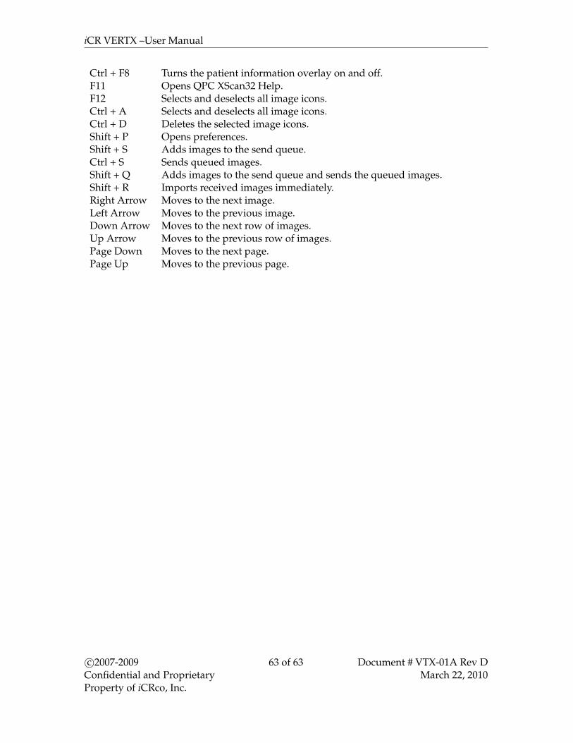
iCR VERTX –User Manual
Ctrl + F8 Turns the patient information overlay on and off.F11 Opens QPC XScan32 Help.F12 Selects and deselects all image icons.Ctrl + A Selects and deselects all image icons.Ctrl + D Deletes the selected image icons.Shift + P Opens preferences.Shift + S Adds images to the send queue.Ctrl + S Sends queued images.Shift + Q Adds images to the send queue and sends the queued images.Shift + R Imports received images immediately.Right Arrow Moves to the next image.Left Arrow Moves to the previous image.Down Arrow Moves to the next row of images.Up Arrow Moves to the previous row of images.Page Down Moves to the next page.Page Up Moves to the previous page.
c©2007-2009Confidential and ProprietaryProperty of iCRco, Inc.
63 of 63 Document # VTX-01A Rev DMarch 22, 2010