vertically cobalt nanoplate arrays based on ... - · pdf file vertically cobalt nanoplate...
TRANSCRIPT

www.spm.co
m.cn
Vertically Cobalt Nanoplate Arrays Based on One-StepElectrochemical Growth and Their Magnetic PropertiesLixia Xu, Shichao Zhang,* Wenbo Liu, and Zhijia Du
School of Materials Science and Engineering, Beihang University, Beijing, China
*S Supporting Information
ABSTRACT: A cobalt nanoplate array (Co NPA) directly grown on acopper substrate by the one-step electrodeposition method is synthesizedwithout any template. Most of the nanoplates with a height of ∼350 nmand length of up to several micrometers stand vertically on the coppersubstrate. The as-prepared cobalt nanoplates have the {100} crystal facetsas the basal plane. By adjusting the electroplating conditions, themorphology and size of the cobalt nanocrystal can be modulated. Owingto the interesting anisotropic nanostructures, remarkable magneticanisotropy is obtained on the Co NPA. In addition, the cobalt nanoplatesare demonstrated to show enhanced magnetic properties compared withother cobalt nanostructures.
■ INTRODUCTIONIn recent years, magnetic nanomaterials have attractedconciderable interest due to their novel properties and manyapplications in electronic, optical, catalytic, magnetic, and otherareas.1−4 Compared to other magnetic metals, cobalt, which hasone of the highest spin imbalances at the Fermi level, hasreceived increasing attention. To achieve better performance inspecial utilities, the anisotropy of the magnetic nanomaterialsmust be well controlled.5,6 To improve the magnetic anisotropyof the materials, much attention has been paid to assemblinglow-dimensional cobalt nanostructures into three-dimensional(3D) complex architectures.7 Up to now, the preparation ofshape-anisotropic cobalt nanocrystals has mainly been achievedin a solution phase containing a surfactant by chemicalmethods. Cobalt nanocrystals with modified intrinsic proper-ties, including nanorods,8 nanodiscs,9 nanocones,10 nano-platelets,11,12 wires,13 cubic nanoskeletons,14 octahedron-likeCo nanocrystals,15 and chains of hollow cobalt mesospheres,16
have been prepared.To develop functional nanodevices, nanostructures are
required to be constructed or assembled on substrates. Thoughmany efforts have been made to understand and control thesurface growth of nanoparticles, the preparation of nano-particles on substrates with well-defined shape and size is still achallenge for nanostructure construction. Electrochemistry is anefficient method for directly producing and patterning metalnanocrystals on conducting substrates. Cobalt crystals havebeen deposited on substrates such as stainless steel, vitreouscarbon, and copper, in electrochemical ways from differentelectrolytic baths containing chloride, sulfate, or thiocyanateaqueous solutions.17−20
In this paper, we report a facile galvanostatic syntheticmethod for a cobalt nanoplate array (Co NPA) by adding
ammonium citrate dibasic ((NH4)2C6H6O7) as a modifyingagent. The experimental results show that most of the preparednanoplates stand vertically on the substrate and there are manyedges or controlled nanogaps in the array. Meanwhile, thegrowth conditions, phase structures, and magnetic properties ofthe 3D Co NPA were systematically studied.
■ EXPERIMENTAL SECTIONAll of the chemicals were analytical grade reagents obtainedfrom commercial sources and were used without furtherpurification. In this work a (99.5%) 1 cm × 2 cm Cu substrateserved as the working electrode in a three-electrode electro-deposition system with a saturated calomel electrode (SCE) asthe reference electrode and a 5.0 cm × 3.5 cm titanium plate asthe counter electrode. The photoresist was used by defining thearea of the Cu plates deposited. Prior to the electrodeposition,the substrates were mechanically polished, rinsed with distilledwater, dipped into a hydrochloric aqueous solution (10%) (60s) to remove the native oxide, and then rinsed again withdistilled water. The electrolyte was comprised of 0.1 MCoSO4·7H2O, 1 M H3BO3, and 0.5 M (NH4)2C6H6O7. Thegalvanostatic technique was carried out under appropriatecurrent control.The morphology of the cobalt crystals was investigated using
field-emission scanning electron microscopy (FESEM; HitachiS-4800) with an energy-dispersive X-ray (EDX) analyzer.Microstructural characterization of the products was accom-plished using X-ray diffraction (XRD; Rigaku D/Max-2400)with Cu Kα radiation (λ = 1.5418 Å) at a step rate of 0.1 deg/s
Received: November 19, 2011Revised: December 26, 2011Published: January 3, 2012
Article
pubs.acs.org/JPCC
© 2012 American Chemical Society 2801 dx.doi.org/10.1021/jp2111583 | J. Phys. Chem. C 2012, 116, 2801−2806

www.spm.co
m.cnin the 2θ range of 40−100°. The topography of the depositswas investigated using a Nanoscope Dimension CSPM5500atomic force microscope working in tapping mode. Consideringthe strong binding force between the cobalt film and cobaltplates, transmission electron microscopy (TEM; JEM-2100F)samples were prepared by scraping a little powder from theelectrode and dispersing it in alcohol by ultrasonic treatment.Sebsequently, the suspension was dropped onto a holey carbonfilm supported on a copper grid. All electrochemical measure-ments were performed in a conventional three-electrode cell atambient temperature (42−87 °C) using an electrochemicalworkstation (PARSTAT 2273). The magnetic moment M wasmeasured as a function of the applied magnetic field rangingfrom −20 to +20 kOe. Measurements were conducted using aPPMS-14T (Quantum Design).
■ RESULTS AND DISCUSSIONThe Co NPAs prepared from the electrolyte with 0.1 MCoSO4, 0.5 M (NH4)2C6H6O7, and 1 M H3BO3 by thegalvanostatic technique with the apparent current densitystrictly controlled to 1.25A/dm2 are shown in Figure 1a,b(taken at an inclination angle of 45°). As can be seen fromFigure 1a,b, most of the cobalt nanoplates orient themselvesperpendicular to the copper substrate. It should be mentionedthat the thickness of the cobalt nanoplates is not unifom; thetop of the nanoplates is sharp with a thickness of ∼30 nm, whilethe base is much thicker (∼150 nm). The topography of theproducts obtained by atomic force microscopy (AFM) is shownin Figure 1c. It indicates that the average height of the
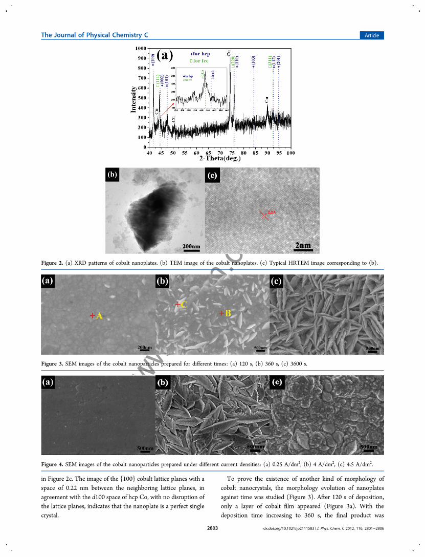
nanoplates is around 400 nm. The energy-dispersive spectrom-etry (EDS) analysis (Figure 1d) shows that the sample isessentially pure cobalt.The XRD pattern of the sample is shown in Figure 2a. No
characteristic peaks due to the impurities of cobalt oxides orhydroxide were detected, indicating that Co crystals with highpurity were obtained by our electrochemical depositionstrategy. The characteristic peaks of the as-prepared productsarise at 2θ = 41.7°, 44.5°, 47.5°, 75.9°, 84.2°, 92.5°, and 94.7°,which have been assigned to hexagonal close-packed (hcp) Co(100), (002), (101), (110), (103), (112), and (201) planes,respectively (JCPDS no. 05-0727). Moreover, the (100)diffraction gives a higher intensity than is expected, whichindicates that the crystallites are abundant in (100) facets andthus their (100) planes tend to be preferentially oriented. Apartfrom the peaks assigned to hcp cobalt, there are some peaksthat can be indexed as face-centered cubic (fcc) cobalt. Thecharacteristic peaks arise at 2θ = 44.2°, 75.9°, and 92.5°, whichhave been assigned to fcc (111), (220), and (311) planesindexed as fcc Co (JCPDS no. 15-0806). This suggests that thehcp and fcc phases of cobalt nanocrystal coexist in the products.We consider that besides the cobalt nanoplates there may existanother kind of morphology of cobalt nanocrystals at thebottom and thus deduce that the two kinds of crystal structures(hcp and fcc) may correspond to the two kinds ofmorphologies of cobalt nanocrystals, respectively. Figure 2 bshows the typical TEM image of a single cobalt nanoplate withperfect platelike shape. The structural orientation of anindividual nanoplate was investigated by HRTEM, as shown
Figure 1. (a) SEM image of the as-synthesized cobalt nanoplates at 65 °C for 1200 s. (b) SEM image of the nanoplates in (a) at 45°. (c) Tappingmode AFM image of the cobalt nanoplates. (d) EDS pattern of the cobalt nanoplates.
The Journal of Physical Chemistry C Article
dx.doi.org/10.1021/jp2111583 | J. Phys. Chem. C 2012, 116, 2801−28062802
www.spm.co
m.cn
in Figure 2c. The image of the {100} cobalt lattice planes with aspace of 0.22 nm between the neighboring lattice planes, inagreement with the d100 space of hcp Co, with no disruption ofthe lattice planes, indicates that the nanoplate is a perfect singlecrystal.
To prove the existence of another kind of morphology ofcobalt nanocrystals, the morphology evolution of nanoplatesagainst time was studied (Figure 3). After 120 s of deposition,only a layer of cobalt film appeared (Figure 3a). With thedeposition time increasing to 360 s, the final product was
Figure 2. (a) XRD patterns of cobalt nanoplates. (b) TEM image of the cobalt nanoplates. (c) Typical HRTEM image corresponding to (b).
Figure 3. SEM images of the cobalt nanoparticles prepared for different times: (a) 120 s, (b) 360 s, (c) 3600 s.
Figure 4. SEM images of the cobalt nanoparticles prepared under different current densities: (a) 0.25 A/dm2, (b) 4 A/dm2, (c) 4.5 A/dm2.
The Journal of Physical Chemistry C Article
dx.doi.org/10.1021/jp2111583 | J. Phys. Chem. C 2012, 116, 2801−28062803

www.spm.co
m.cn
dominated by a cobalt film together with only a few narrownanoplates with a length of 500 nm (Figure 3b). The EDSdetails corresponding to points A−C) of Figure 3a,b are shownin Figure S1 (Supporting Information). If the deposition timewas further increased to 3600 s, the vertically standing cobaltnanoplates were denser in distribution and ever-increased insize (Figure 3c), but the morphology remained stable. On thebasis of the above analysis, the formation of Co NPA could beexplained from the point of view below. At the prophase of thedeposition, a layer of cobalt film is deposited on the substrate.The ammonium and citrate ions preferentially adsorb oncertain orientations, thereby retarding the growth rate of cobaltalong certain directions while the surface without surfactantadsorption grows preferentially.21 In addition, the orientedelectric field between the working electrode and the counterelectrode assists the vertical growth of nanoplates, since theelectric line force was perpendicular to the substrate.22,23
The growth rate of the crystal plays an important role in theformation of anisotropic nanocrystals. One of the advantages ofthe electrodeposition is that the rate of the crystal growth canbe controlled by adopting different current densities. Themorphology evolution of cobalt nanocrystals on a coppersubstrate as a function of the current density is clearly seen inFigure 4. Under a current density of 0.25 A/dm2, only a smoothcobalt film was generated in Figure 4a. Vertical cobaltnanoplates could be prepared only under a current densityranging from 0.75 to 2.75 A/dm2 (Figure S2, SupportingInformation). When the current density increased to 3.5 A/dm2, it showed trapeziform nanoplates standing on thesubstrate (Figure 4b). However, the thickness and lengthobviously increased from 0.75 to 3.5 A/dm2 . When the currentdensity reached 4.5 A/dm2, the cobalt nanoplates becameirregular bulk particles (Figure 4c). This is because the cobaltcrystals are prone to grow at almost the same speed alongdifferent crystal orientations under a high current density,namely, isotropic growth of cobalt nanocrystals.It can be seen from the XRD patterns of the samples
corresponding to Figures 1a and Figure 4b,c (Figure S3,Supporting Information) that the intensity of the characteristicpeaks of (100), one plane of hcp, decrease as the currentdensity increases, while the intensity of the characteristic peaksof (111), one plane of fcc, increase as the current densityincreases. This indicates that an electrodeposited cobaltnanocrystal favors the hcp structure at lower negative currentdensities, the fcc structure at higher negative current densities,and mixed phases of fcc and hcp between them. The presentresults demonstrate that different crystal structures of cobaltcrystals can be obtained through simply changing thedeposition current density.
In an electrochemical deposition route, temperature has adirect influence on the formation of the crystal nuclei andgrowth by affecting the diffusion of primary particles in theelectrolyte and the adsorption on the crystal surface, thusaffecting the morphology and crystal structures of the products.At 25 °C (Figure 5a) and 85 °C (Figure 5b), narrow cobaltnanoplates started to emerge. Co NPAs can only be foundgrowing orderly at temperatures ranging from 45 to 75 °C(Figure S4, Supporting Information). When the temperature isincreased to 95 °C (Figure 5c), the formation of particles isbrought about. It is generally recognized that a highertemperature favors growth vertical to the substrates, becausewith an increase of temperature, the diffusion layer of theadsorptive atom will be thicker, and the roughness of thedeposit will be increased. However, if the temperature exceeds acertain limit, the electroplating system will change, resulting indecomposition of the complex.Complexants have been widely utilized to modify the
morphology of metallic nanomaterials prepared by electro-deposition of the corresponding metallic salts. To furtherinvestigate the influence of complexants, comparison experi-ments without ammonium or citrate ions were performed. Themorphology of the as-obtained products (Figure S5, SupportingInformation) is similar to that of the products with bothammonium and citrate ions ((NH4)2C6H6O7) (Figure 1a) butmuch thicker, lower, and sparser. This implies that ammoniumand citrate ions have a great effect on promotion of theorientation growth of the cobalt nanoparticles. The X-raydiffraction pattern of the samples (Figure S6, SupportingInformation) shows that the characteristic peaks of two kinds ofelectrodeposited samples aforementioned arise at almost thesame positions, which indicates that they have almost the samecrystal structure.The hysteresis loops with the field perpendicular (out-of-
plane) and parallel (in-plane) to the Cu substrate for the cobaltnanoplates corresponding to Figure 1a are shown in Figure 6a.The values of squareness SQ (ratio of remanence to saturationmagnetization, Mr/Ms) are SQ∥ = 0.559 and SQ⊥ = 0.0306,which indicates that the easy magnetization axis is parallel tothe substrate plane and hence perpendicular to the cobaltnanoplate axis. The coercivity of the Co NPAs is ∼285.6 and∼46.1 Oe (1 Oe = 103/4π A m−1) for H⊥ and H∥, respectively.It is obvious that the loop measured in H⊥ has a largercoercivity (∼285.6 Oe) in comparison to that measured in H∥(∼46.1 Oe), indicating a remarkable magnetic anisotropy.Compared with the coercivity value of the bulk one (a few tensof oersteds at room temperature) and the similar micro-structures reported previously, the cobalt nanoplates with amagnetic field applied perpendicular to the copper substrate
Figure 5. SEM images of the cobalt nanoparticles prepared under different temperatures: (a) 25 °C, (b) 85 °C, (c) 95 °C.
The Journal of Physical Chemistry C Article
dx.doi.org/10.1021/jp2111583 | J. Phys. Chem. C 2012, 116, 2801−28062804

www.spm.co
m.cn
exhibit a distinct enhanced coercive force, which is attributed totheir special 3D structure. Figure 7a presents the relationship ofHc values versus temperature when the applied field is paralleland perpendicular to the substrate. It clearly shows that Hc issignificantly decreased as the temperature increases. Figure 7billustrates the typical angular dependence of the coercivity andsquareness for Co NPAs, where θ is the angle between thesubstrate and the applied field during measurement. It can beobserved that the maximum coercivity occurs at 75° while themaximum squareness occurs when the applied field is parallel tothe substrate. Also, the squareness decreases as θ increases.These results are consistent with the general trend of therelationship between the squareness and θ.
■ CONCLUSIONS
In summary, hcp Co NPAs standing vertically on the substratewere synthesized via a facile complexant-assisted galvanostaticmethod. Ammonium citrate dibasic can be used to effectivelyassist the formation of shape-anisotropic cobalt nanocrystals. Byadjusting the electroplating conditions, the size and shape ofthe cobalt nanoplates can be controlled. A discernibledifference is observed between the hysteresis loops when His applied parallel (H∥ = 27.1 Oe) and perpendicular (H⊥ =285.6 Oe) to the copper substrate. A ferromagnetic nature witha significantly enhanced magnetic coercivity (H⊥ = 285.6 Oe)can be exhibited due to the anisotropic shape and the hcpcrystal structure. This simple strategy also can be easily
extended to fabricate other metal nanoplate arrays on thesubstrate, leading to a broad promising application in manyfields.
■ ASSOCIATED CONTENT*S Supporting InformationEDS patterns of the cobalt nanoplates corresponding to pointsA−C in Figure 3, SEM images of the cobalt nanoplatesprepared under different current densities and differenttemperatures and of the platelike Co nanocrystals depositionedwithout ammonium and citrate ions, and XRD patterns ofcobalt plates depositioned under different currents and of theCo nanocrystals depositioned with and without ammonium andcitrate ions. This material is available free of charge via theInternet at http://pubs.acs.org.
■ AUTHOR INFORMATIONCorresponding Author*E-mail: [email protected].
■ ACKNOWLEDGMENTSThis work was supported by the National Natural ScienceFoundation of China (Grants 50954005 and 51074011), theNational Basic Research Program of China (Grant2007CB936502), and the National 863 Program (Grants2006AA03Z230 and 2008AA03Z208).
■ REFERENCES(1) Legrand, J.; Ngo, A. T.; Petit, C.; Pileni, M. P. Adv. Mater. 2001,13, 58−+.(2) Legrand, J.; Petit, C.; Pileni, M. P. J. Phys. Chem. B 2001, 105,5643−5646.(3) Tzitzios, V.; Niarchos, D.; Gjoka, M.; Boukos, N.; Petridis, D. J.Am. Chem. Soc. 2005, 127, 13756−13757.(4) Rafailovic, L. D.; Karnthaler, H. P.; Trisovic, T.; Minic, D. M.Mater. Chem. Phys. 2010, 120, 409−416.(5) Puntes, V. F.; Krishnan, K. M.; Alivisatos, A. P. Science 2001, 291,2115−2117.(6) Li, M.; Hang, T.; Fei, Q.; Mao, D. Nanotechnology 2008, 19.(7) Soumare, Y.; Garcia, C.; Maurer, T.; Chaboussant, G.; Ott, F.;Fievet, F.; Piquemal, J. Y.; Viau, G. Adv. Funct. Mater. 2009, 19, 1971−1977.(8) Srikala, D.; Singh, V. N.; Banerjee, A.; Mehta, B. R.; Patnaik, S. J.Nanosci. Nanotechnol. 2009, 9, 5627−5632.(9) Hang, T.; Hu, A. M.; Li, M.; Mao, D. L. CrystEngComm 2010, 12,2799−2802.
Figure 6. Magnetic hysteresis loop of the Co sample.
Figure 7. (a) Coercive field against temperature. (b) Angular dependence of coercivity and squareness for the cobalt nanoplates.
The Journal of Physical Chemistry C Article
dx.doi.org/10.1021/jp2111583 | J. Phys. Chem. C 2012, 116, 2801−28062805

www.spm.co
m.cn
(10) Zhu, Y.; Yang, Q.; Zheng, H.; Yu, W.; Qian, Y. Mater. Chem.Phys. 2005, 91, 293−297.(11) Shin, N. C.; Lee, Y.-H.; Shin, Y. H.; Kim, J.; Lee, Y.-W. Mater.Chem. Phys. 2010, 124, 140−144.(12) Xie, B. Q.; Qian, Y. T.; Zhang, S. Y.; Fu, S. Q.; Yu, W. C. Eur. J.Inorg. Chem. 2006, 2454−2459.(13) Wang, X.; Fu, H. B.; Peng, A. D.; Zhai, T. Y.; Ma, Y.; Yuan, F.L.; Yao, J. N. Adv. Mater. 2009, 21, 1636−+.(14) Wang, X.; Yuan, F. L.; Hu, P.; Yu, L. J.; Bai, L. Y. J. Phys. Chem.C 2008, 112, 8773−8778.(15) Guo, L.; Liang, F.; Wen, X. G.; Yang, S. H.; He, L.; Zheng, W.Z.; Chen, C. P.; Zhong, Q. P. Adv. Funct. Mater. 2007, 17, 425−430.(16) Rios-Reyes, C. H.; Granados-Neri, M.; Mendoza-Huizar, L. H.Quim. Nova 2009, 32, 2382−2386.(17) Harti, H.; Bubendorff, J. L.; Florentin, A.; Pirri, C.; Ebothe, J. J.Cryst. Growth 2011, 319, 79−87.(18) Karami, H.; Mohammadzadeh, E. Int. J. Electrochem. Sci. 2010, 5,1032−1045.(19) Grujicic, D.; Pesic, B. Electrochim. Acta 2004, 49, 4719−4732.(20) Yan, F.; Luo, Z. X.; Zhou, X. F.; Yao, H. N. Mater. Chem. Phys.2008, 107, 91−95.(21) Bao, Z. L.; Kavanagh, K. L. J. Cryst. Growth 2006, 287, 514−517.(22) Jia, F. L.; Wong, K. W.; Du, R. X. Electrochem. Commun. 2009,11, 519−521.(23) Jia, F. L.; Wong, K. W.; Zhang, L. Z. J. Phys. Chem. C 2009, 113,7200−7206.
The Journal of Physical Chemistry C Article
dx.doi.org/10.1021/jp2111583 | J. Phys. Chem. C 2012, 116, 2801−28062806