version 1docs.renegaderv.com/spyder controls/tech call troubleshooting... · switch panels 2 switch...
TRANSCRIPT
0
Tech Call Troubleshooting Guide
Version 1

1
1 TABLE OF CONTENTS
SWITCH PANELS
2 SWITCH PANELS - WIRELESS
3 SWITCH PANELS – WIRED
POWER DISTRIBUTION PANELS
6 G6A
8 G7A
10 G8
12 G9
14 G5A
16 G5D
20 POWER MANAGEMENT MODULE (PMM)
CLIMATE CONTROL MODULES
22 AIRCON MODULES
23 VENT FAN MODULES
SLIDES
24 SLIDE CONTROLS
SHADES
26 G5A SHADE MODULES
TOUCHSCREENS
28 4.3” SCREENS
30 7” SPECTRUM SCREENS
32 7” LYRA SCREENS
33 10” and 7” VEGATOUCH SCREENS
34 VEGATOUCH SCREEN REPLACEMENT
WIRELESS MODULES
41 MIRA
45 PLUTO
NETWORK TROUBLESHOOTING
46 NETWORK TROUBLESHOOTING
48 TECH SUPPORT CONTACT INFO
49 WARRANTY PROCEDURES
2
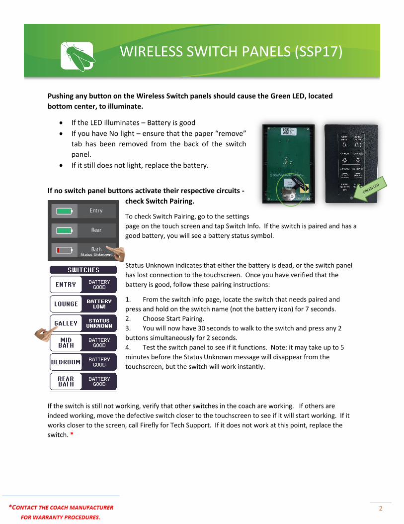
Pushing any button on the Wireless Switch panels should cause the Green LED, located
bottom center, to illuminate.
• If the LED illuminates – Battery is good
• If you have No light – ensure that the paper “remove”
tab has been removed from the back of the switch
panel.
• If it still does not light, replace the battery.
If no switch panel buttons activate their respective circuits -
check Switch Pairing.
To check Switch Pairing, go to the settings
page on the touch screen and tap Switch Info. If the switch is paired and has a
good battery, you will see a battery status symbol.
Status Unknown indicates that either the battery is dead, or the switch panel
has lost connection to the touchscreen. Once you have verified that the
battery is good, follow these pairing instructions:
1. From the switch info page, locate the switch that needs paired and
press and hold on the switch name (not the battery icon) for 7 seconds.
2. Choose Start Pairing.
3. You will now have 30 seconds to walk to the switch and press any 2
buttons simultaneously for 2 seconds.
4. Test the switch panel to see if it functions. Note: it may take up to 5
minutes before the Status Unknown message will disappear from the
touchscreen, but the switch will work instantly.
If the switch is still not working, verify that other switches in the coach are working. If others are
indeed working, move the defective switch closer to the touchscreen to see if it will start working. If it
works closer to the screen, call Firefly for Tech Support. If it does not work at this point, replace the
switch. *
WIRELESS SWITCH PANELS (SSP17)

3
Network Connection
RVC switches are connected to the CAN network by cables called “drop
cables.” The red and black wires supply power to the switch while the
blue and white wires provide communication to the network. Many
switch panel issues can be caused by loose wiring at this connector
known as the Mini Plug. Please see the Network Pinout diagram. It is
important to note that occasionally the blue wire may be green.
Some switches will have a built-in network cable known as a pig tail.
Other switches will have a female mini socket on the back and will not
have a pig tail attached.
When a wired switch panel is connected to the network, a network
status LED light will illuminate solid green. This NET LED will be
located underneath the bezel of the switch panel. If the NET LED
status is anything other than solid green, please refer to the
Network Troubleshooting Page.
Testing Switches
Test a wired switch by removing it from the wall and plugging it
directly into the Net Port. This will help to rule out wiring issues. If
the switch works while it is plugged directly in, you’ll know that the
switch isn’t defective. You’ll then want to investigate the wiring.
Switches that don’t have a pig tail will require the use
of a separate network cable to test at the Net Port.
This type of switch can also be tested by removing a
working switch and testing at its location.
Network Pinout
Red – 12V positive
White – CAN High
Blue/Green – CAN Low
Black - Ground
WIRED RVC SWITCH PANELS
NET LED
Removing the Bezel Note: The cover for each switch panel is removed through inserting a small screw driver or using a finger to gently pry off.
Net Port – allows direct
access to the network
4
A SWITCH PANEL HAS GONE DARK AND NO LONGER FUNCTIONS.
Remove the switch panel from the wall. Do the network wires seem like they have a loose
connection or has one of the wires come loose?
• Yes – repair the wiring and retest the switch
• No – remove the switch from the wall and plug it directly into the power distribution
center’s Net Port to test (G5, G6, etc.).
Does it work while plugged in directly to the Net Port?
• Yes – There may be a problem with the wiring running to the switch. Check all
connections in the wiring running to the switch.
• No – Replace the switch. *
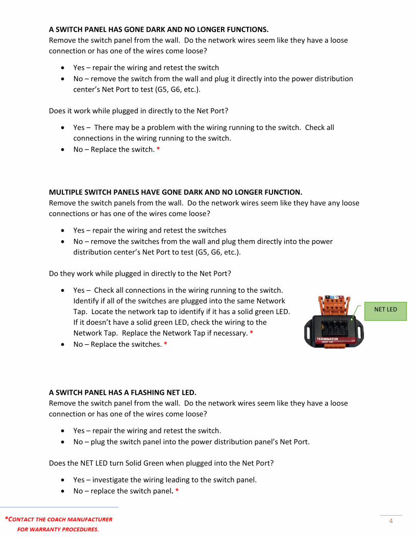
MULTIPLE SWITCH PANELS HAVE GONE DARK AND NO LONGER FUNCTION.
Remove the switch panels from the wall. Do the network wires seem like they have any loose
connections or has one of the wires come loose?
• Yes – repair the wiring and retest the switches
• No – remove the switches from the wall and plug them directly into the power
distribution center’s Net Port to test (G5, G6, etc.).
Do they work while plugged in directly to the Net Port?
• Yes – Check all connections in the wiring running to the switch.
Identify if all of the switches are plugged into the same Network
Tap. Locate the network tap to identify if it has a solid green LED.
If it doesn’t have a solid green LED, check the wiring to the
Network Tap. Replace the Network Tap if necessary. *
• No – Replace the switches. *
A SWITCH PANEL HAS A FLASHING NET LED.
Remove the switch panel from the wall. Do the network wires seem like they have a loose
connection or has one of the wires come loose?
• Yes – repair the wiring and retest the switch.
• No – plug the switch panel into the power distribution panel’s Net Port.
Does the NET LED turn Solid Green when plugged into the Net Port?
• Yes – investigate the wiring leading to the switch panel.
• No – replace the switch panel. *
NET LED
5
MULTIPLE SWITCH PANELS HAVE A FLASHING NET LED.
See the Network Troubleshoot Guide and perform a Network Resistance Test. Call Firefly
Integrations for tech support if you do not measure 60 ohms.
A BUTTON ON A SWITCH PANEL NO LONGER FUNCTIONS.
You will need to ensure that there is not a problem with the distribution panel.
Can you operate the same function from another switch/touchscreen in the coach?
• Yes – the switch panel might be defective and could need to be replaced. Test the
switch at another location to rule out the wiring to the switch. Replace the switch if
necessary. *
• No – See the Distribution Panel Troubleshooting page.
A SWITCH PANEL LIGHTS UP BUT NO BUTTONS WILL FUNCTION.
Remove the switch panel and check the network connections and the NET LED status. It is likely
that one of the communication wires have come loose. If all connections look solid, test the
switch in the power distribution center’s Net Port. Does it work while plugged in directly?
• Yes – There may be a problem with the wiring running to the switch. Check all
connections in the wiring running to the switch.
• No – Replace the switch. *

6
G6A Panel
The G6A control panel is the most common type
of power distribution center. This panel receives
the signals sent from your switch panels and
performs the actions that have been requested
by activating and deactivating the required
circuits.
Every circuit controlled by the G6A is numbered
and listed on the front label (load list). A
corresponding numbered LED will illuminate
green whenever a particular circuit is on. For
instance, if you press the Lounge Light button on
your switch panel, the green LED beside circuit 1
will illuminate and the Lounge Light will turn on
(Fig 1).
Resettable breakers are also numbered and listed
on the G6A label. Simply press the white tip to
reset a breaker if one has tripped.
Testing output voltage using a Multi-meter.
Ensure that the G6 circuit is on and that the
green LED is illuminated.
To test the output voltage for the Lounge
Light example, touch the positive lead to the
output pin for Circuit 1 and the negative
lead to the ground stud (as pictured).
If you do not measure at least 12V it is likely
that the relay card in the G6 will need to be
replaced. *
DC Power Distribution Panels
Fig 1
NET LED
7
A GREEN LED ON THE G6 WON’T ILLUMINATE WHEN A BUTTON IS PRESSED ON A SWITCH
PANEL.
Ensure that other functions on the switch panel are working and all system Net LED’s are solid
green. Test the light from another device or location if possible. If the switch panel is not
defective, the green LED on the G6 should illuminate when the button is pressed on a switch
panel. If you have determined that the switch isn’t defective, it is likely that the G6 driver card
has an issue and the G6 would need to be replaced. *
THE GREEN CIRCUIT LED FOR A PARTICULAR LIGHT WILL ILLUMINATE, BUT THE LIGHT IN THE
COACH IS NOT WORKING.
Let’s use the example from the previous page. In this scenario, the Lounge Light button is
pressed but the Lounge Light (Ceiling 1) will not turn on in the coach.
First, check the switch panel button for feedback? Did the switch panel button change color?
• Yes – Continue reading.
• No – Troubleshoot the network or the switch panel itself before continuing.
Look at the load list on the G6A panel. Is the Green LED beside circuit 1 illuminated?
• Yes – the G6 has received the signal from the switch panel. Test the outputs for Circuit 1
on the back of the G6 for 12V output. If an output of 12V is measured, the firefly system
is working correctly and the coach wiring will need to be investigated.
• No – Ensure that the switch is not defective. Test with a different switch or plug the
switch directly into the Net Port to help determine if the switch has a problem. It is
possible that the G6 has a faulty driver card and would need to be replaced. *
LIGHTS ARE COMING ON IN THE COACH WITHOUT BEING ACTIVATED BY A SWITCH PANEL OR
LIGHTS IN THE COACH WILL NOT SHUT OFF.
Shut down 12V power to the coach (power cycle) for 10 seconds. Did the lights comes back on
automatically when power was returned to the coach?
• Yes – Remove all switch panels from the network that control those particular lights and
power cycle the coach again. If the lights still turn on by themselves once power has
been reapplied to the coach, check the Green LED on the G6. If it is on, you probably
have a faulty driver card and the G6 will likely have to be replaced. * If it is off, check
the output voltage on the back of the G6 for the circuits in question. If you are
measuring 12V on the circuits in questions while the Green LED is off, you will need to
replace the card in question. * You should not be getting an output while the G6 circuit
LED is off.
• No – Plug the switches back into the network one at a time to see if they successfully
operate. If a switch operates successfully, leave it plugged it in. Add the rest of the
switches back into the network one at a time. If any lights automatically turn on once a
switch is connected, that switch is defective. *
8
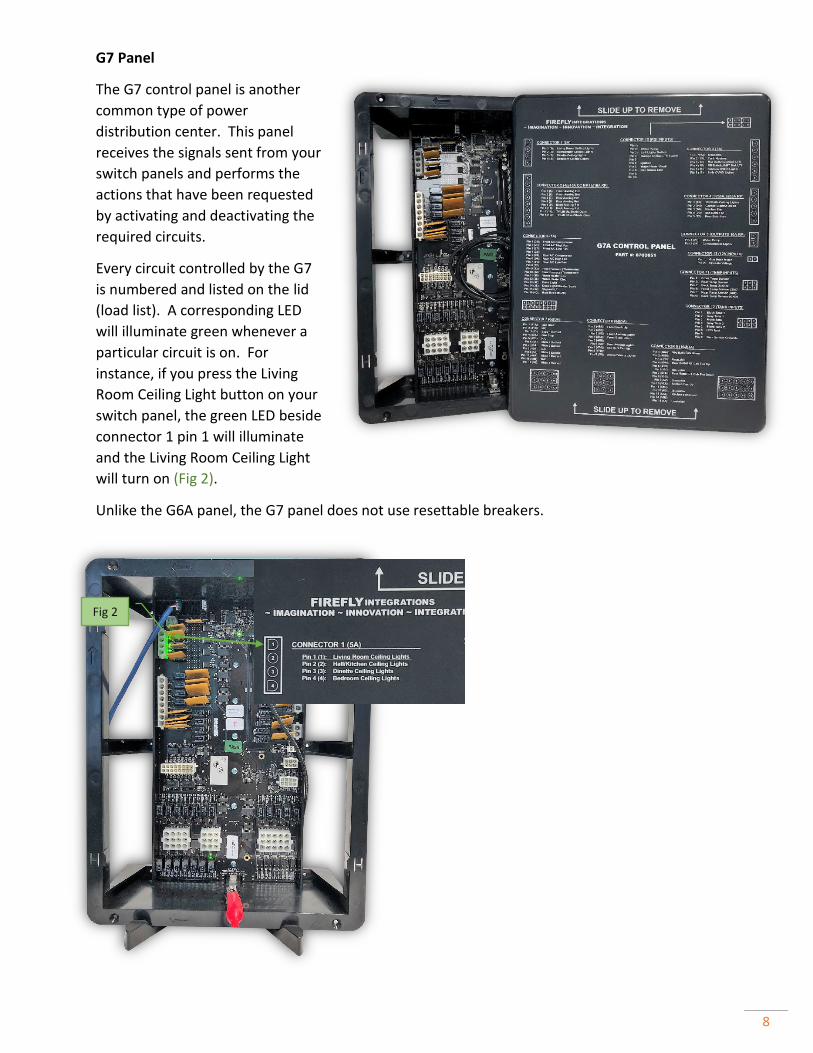
G7 Panel
The G7 control panel is another
common type of power
distribution center. This panel
receives the signals sent from your
switch panels and performs the
actions that have been requested
by activating and deactivating the
required circuits.
Every circuit controlled by the G7
is numbered and listed on the lid
(load list). A corresponding LED
will illuminate green whenever a
particular circuit is on. For
instance, if you press the Living
Room Ceiling Light button on your
switch panel, the green LED beside
connector 1 pin 1 will illuminate
and the Living Room Ceiling Light
will turn on (Fig 2).
Unlike the G6A panel, the G7 panel does not use resettable breakers.
Fig 2

9
NOTHING HAPPENS WHEN A BUTTON IS PRESSED ON A SWITCH PANEL OR FROM THE
TOUCHSCREEN.
Verify that the NET LED is illuminated solid green on the G7. If the NET LED is flashing, perform
a power cycle and check the NET LED again. If the NET LED is displaying anything other than
solid green, see the Network Troubleshooting guide.
A BUTTON ON A SWITCH PANEL NO LONGER FUNCTIONS.
Typically G7 panels are used with wireless SSP17 switch panels. Please refer to SSP17
troubleshooting on Page 2.
A FUNCTION WILL NOT WORK FROM THE TOUCHSCREEN.
In this example, we will assume that you are attempting to turn on
the Living Room Ceiling Lights. Is the screen showing feedback when
you press the Living Ceiling button?
• Yes – With the circuit on, check that the circuit LED is on.
Now, check the output on the G7 panel with a multi-meter to
make sure that it is sending output voltage. If it is not giving
12V output, replace the G7 panel. * If it is giving output,
check the coach wiring to the lights.
• No – Check the NET LED on the back of the touch screen and on the G7 to make sure
that they are solid green. If they are, call Firefly Tech Support (574-825-4600).
NET LED
ON
OFF
Multi-
meter
GROUND
Test Positive Output Channels as shown:
NOTE: ALWAYS POWER CYCLE THE 12V POWER TO THE COACH BEFORE TROUBLESHOOTING.
Simply flip the battery disconnect switch for 10 seconds and turn it back on. A power cycle can fix
many problems that seem out of the ordinary.
10
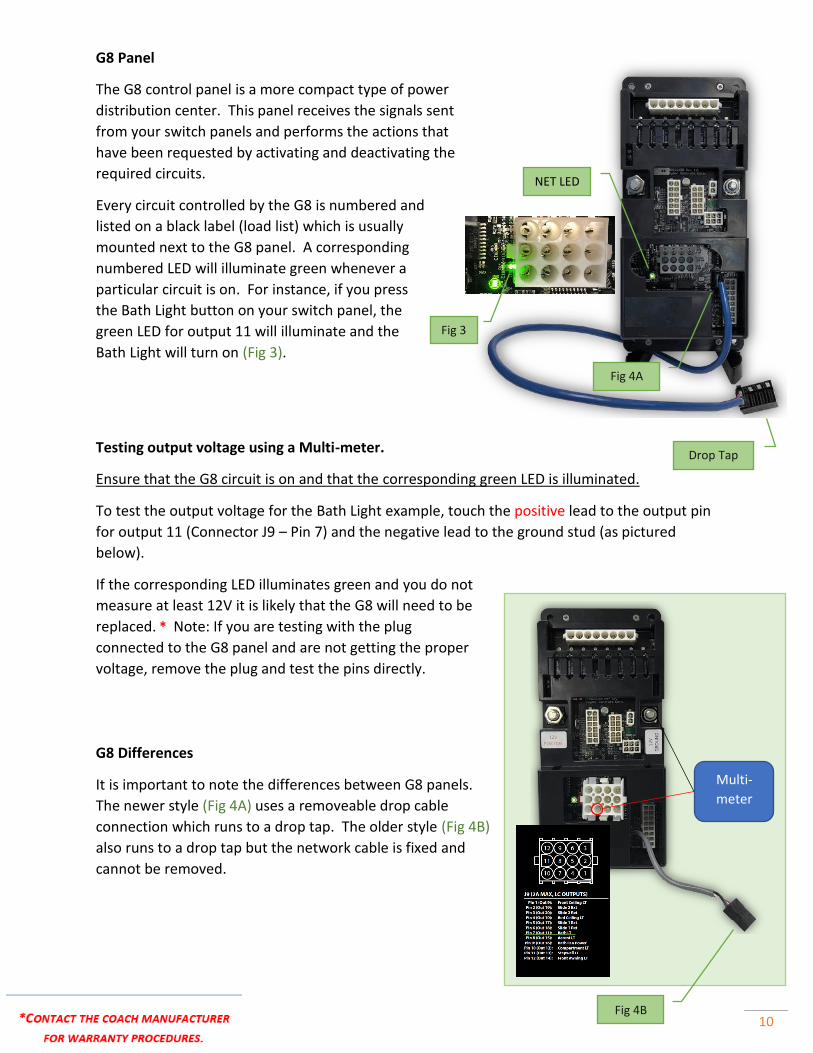
G8 Panel
The G8 control panel is a more compact type of power
distribution center. This panel receives the signals sent
from your switch panels and performs the actions that
have been requested by activating and deactivating the
required circuits.
Every circuit controlled by the G8 is numbered and
listed on a black label (load list) which is usually
mounted next to the G8 panel. A corresponding
numbered LED will illuminate green whenever a
particular circuit is on. For instance, if you press
the Bath Light button on your switch panel, the
green LED for output 11 will illuminate and the
Bath Light will turn on (Fig 3).
Testing output voltage using a Multi-meter.
Ensure that the G8 circuit is on and that the corresponding green LED is illuminated.
To test the output voltage for the Bath Light example, touch the positive lead to the output pin
for output 11 (Connector J9 – Pin 7) and the negative lead to the ground stud (as pictured
below).
If the corresponding LED illuminates green and you do not
measure at least 12V it is likely that the G8 will need to be
replaced. * Note: If you are testing with the plug
connected to the G8 panel and are not getting the proper
voltage, remove the plug and test the pins directly.
G8 Differences
It is important to note the differences between G8 panels.
The newer style (Fig 4A) uses a removeable drop cable
connection which runs to a drop tap. The older style (Fig 4B)
also runs to a drop tap but the network cable is fixed and
cannot be removed.
Fig 4A
Fig 3
Multi-
meter
Drop Tap
Fig 4B
NET LED
11
A GREEN LED ON THE G8 WON’T ILLUMINATE WHEN A BUTTON IS PRESSED ON A SWITCH
PANEL.
Ensure that other functions on the switch panel are working and all system NET LED’s are solid
green. Test the light from another device or location if possible. If the switch panel is not
defective, the green LED on the G8 should illuminate when the button is pressed on a switch
panel. If you have determined that the switch isn’t defective, it is likely that the G8 has an issue
and would need to be replaced. *
THE GREEN CIRCUIT LED FOR A PARTICULAR LIGHT WILL ILLUMINATE, BUT THE LIGHT IN THE
COACH IS NOT WORKING.
Let’s use the example from the previous page. In this scenario, the Bath Light button is pressed
but the Bath Light will not turn on in the coach.
First, check the switch panel button for feedback? Did the wired switch panel button change
color (Wireless switch panel buttons will not show feedback)?
• Yes – Continue reading.
• No – Troubleshoot the network or the switch panel itself before continuing.
Look at the load list for the G8 panel. Is the Green LED beside output 11 illuminated?
• Yes – the G8 has received the signal from the switch panel. Test the voltage for output
11 on the G8. If an output of 12V is measured, the firefly system is working correctly
and the coach wiring will need to be investigated. If less than 12V is showing and you
are measuring directly on the wiring harness connector, unplug the connector and test
the G8 pins directly to verify.
• No – Ensure that the switch is not defective. Test with a different switch or plug the
switch directly into the Net Port to help determine if the switch has a problem. It is
possible that the G8 is faulty and would need to be replaced. *
LIGHTS ARE COMING ON IN THE COACH WITHOUT BEING ACTIVATED BY A SWITCH PANEL OR
LIGHTS IN THE COACH WILL NOT SHUT OFF.
Shut down 12V power to the coach (power cycle) for 10 seconds. Did the lights comes back on
automatically when power was returned to the coach?
• Yes – Remove all switch panels from the network that control those particular lights and
power cycle the coach again. If the lights still turn on by themselves once power has
been reapplied, check the Green LED on the G8. If it is on, replace the G8. *
• No – Plug the switches back into the network one at a time to see if they successfully
operate. If a switch operates successfully, leave it plugged it in. Add the rest of the
switches back into the network one at a time. If any lights automatically turn on once a
switch is connected, that switch is defective. *
12
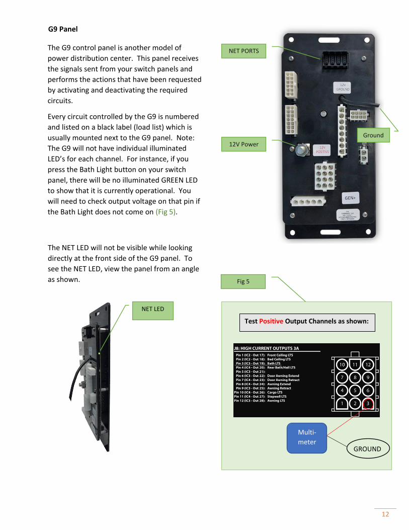
G9 Panel
The NET LED will not be visible while looking
directly at the front side of the G9 panel. To
see the NET LED, view the panel from an angle
as shown.
12V Power
The G9 control panel is another model of
power distribution center. This panel receives
the signals sent from your switch panels and
performs the actions that have been requested
by activating and deactivating the required
circuits.
Every circuit controlled by the G9 is numbered
and listed on a black label (load list) which is
usually mounted next to the G9 panel. Note:
The G9 will not have individual illuminated
LED’s for each channel. For instance, if you
press the Bath Light button on your switch
panel, there will be no illuminated GREEN LED
to show that it is currently operational. You
will need to check output voltage on that pin if
the Bath Light does not come on (Fig 5).
Ground
NET PORTS
GROUND
Multi-
meter
Test Positive Output Channels as shown:
NET LED
Fig 5

13
A GREEN LED ON THE G9 WON’T ILLUMINATE WHEN A BUTTON IS PRESSED ON A SWITCH
PANEL.
The only LED on the G9 is the NET LED as shown on the previous page. If the NET LED will not
illuminate, verify the power going to the G9 panel and see the Network Troubleshooting guide.
THE NET LED IS ILLUMINATED, BUT THE LIGHT IN THE COACH IS NOT WORKING.
Let’s use the example from the previous page. In this scenario, the Bath Light button is pressed
but the Bath Light will not turn on in the coach.
First, check the switch panel button for feedback? Did the wired switch panel button change
color (Wireless switch panel buttons will not show feedback)?
• Yes – Continue reading.
• No – Troubleshoot the network or the switch panel itself before continuing.
Verify the voltage of the Bath Lights output on the G9 (see Figure 1 on the previous page). If
you don’t measure at least 12V coming directly from the pins, replace the G9. *
LIGHTS ARE COMING ON IN THE COACH WITHOUT BEING ACTIVATED BY A SWITCH PANEL OR
LIGHTS IN THE COACH WILL NOT SHUT OFF.
Shut down 12V power to the coach (power cycle) for 10 seconds. Did the lights comes back on
automatically when power was returned to the coach?
G9 panels will typically be used with Wireless Switch Panels. Continue reading for Wired Switch
Panels.
• Yes – Remove all wired switch panels from the network that controls those particular
lights and power cycle the coach again. If the lights still turn on by themselves once
power has been reapplied to the coach, check the output voltage for circuit in question
on the G9. If it is giving an output, replace the G9. *
• No – Plug the wired switches back into the network one at a time to see if they
successfully operate. If a switch operates successfully, leave it plugged in. Add the rest
of the switches back into the network one at a time. If any lights automatically turn on
once a switch is connected, that switch is defective. *

14
G5A DC Panel
Channels 1-24 Unswitched/Fused Outputs
Red Indicator On = Fuse blown
Red Indicator Off = Fuse good or no active load
The G5 DC Panel has been quite popular in previous
model year coaches. The system does not use
resettable breakers, but instead uses mini fuses on
each channel.
Channels 1-24 are not controlled by switch panels.
These channels are fused on the panel only. If a
function stops responding on one of these channels,
test and replace the fuse if necessary.
Replacement Fuse – Mini-Blind Type
(Littlefuse 257 series or Bussman ATM series)
15A Max Fuse – Channels 1-8 & 17-24
30A Max Fuse – Channels 9-18
NET LED
Channels 37-44 AUX Relay Outputs
Green Indicator = Channel on
No indicator = Channel off
Note: A built-in 3A auto-reset PTC fuse for each
channel provides over-current protection. The
indicator DOES NOT show when this fuse is open or
in short-circuit condition.
Channels 45-64 Relay Outputs
Green Indicator = Channel on
Red Indicator = Channel On, Fuse blown
No indicator = Channel off
(Littlefuse 257 series or Bussman ATM series)
Net Fuse 5A Max – This fuse provides power to the
network powered devices only (typically all switch
panels). NOTE: this fuse does not have an indicator
light for fuse status.
NET PORT
Channels 25-36 are Dimming Outputs
Green Indicator = Channel on
Red Indicator = Channel On, Fuse blown
No indicator = Channel off
15
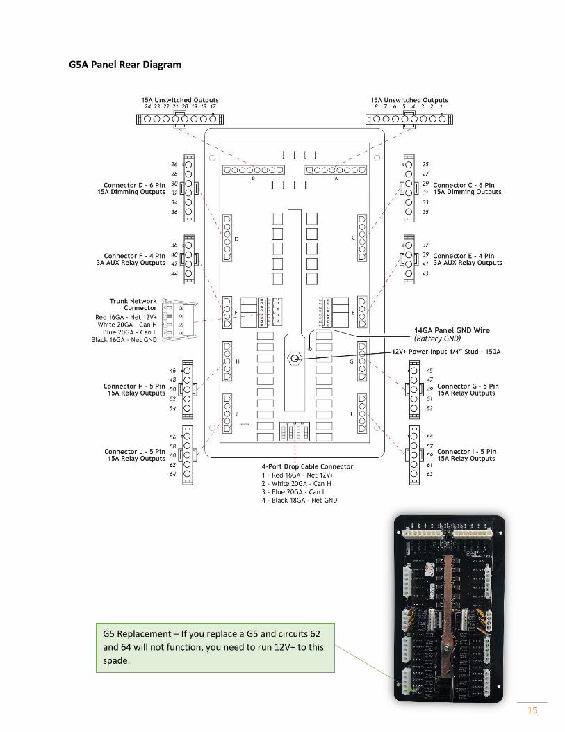
G5 Replacement – If you replace a G5 and circuits 62
and 64 will not function, you need to run 12V+ to this
spade.
G5A Panel Rear Diagram
16
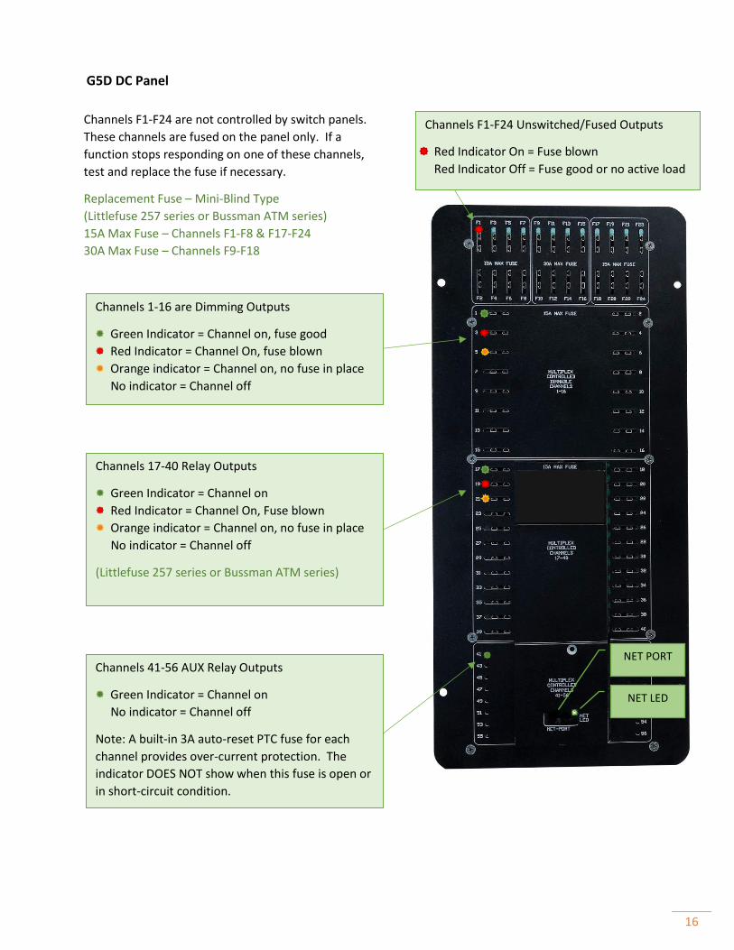
G5D DC Panel
Channels F1-F24 Unswitched/Fused Outputs
Red Indicator On = Fuse blown
Red Indicator Off = Fuse good or no active load
Channels F1-F24 are not controlled by switch panels.
These channels are fused on the panel only. If a
function stops responding on one of these channels,
test and replace the fuse if necessary.
Replacement Fuse – Mini-Blind Type
(Littlefuse 257 series or Bussman ATM series)
15A Max Fuse – Channels F1-F8 & F17-F24
30A Max Fuse – Channels F9-F18
Channels 1-16 are Dimming Outputs
Green Indicator = Channel on, fuse good
Red Indicator = Channel On, fuse blown
Orange indicator = Channel on, no fuse in place
No indicator = Channel off
Channels 41-56 AUX Relay Outputs
Green Indicator = Channel on
No indicator = Channel off
Note: A built-in 3A auto-reset PTC fuse for each
channel provides over-current protection. The
indicator DOES NOT show when this fuse is open or
in short-circuit condition.
Channels 17-40 Relay Outputs
Green Indicator = Channel on
Red Indicator = Channel On, Fuse blown
Orange indicator = Channel on, no fuse in place
No indicator = Channel off
(Littlefuse 257 series or Bussman ATM series)
NET PORT
NET LED
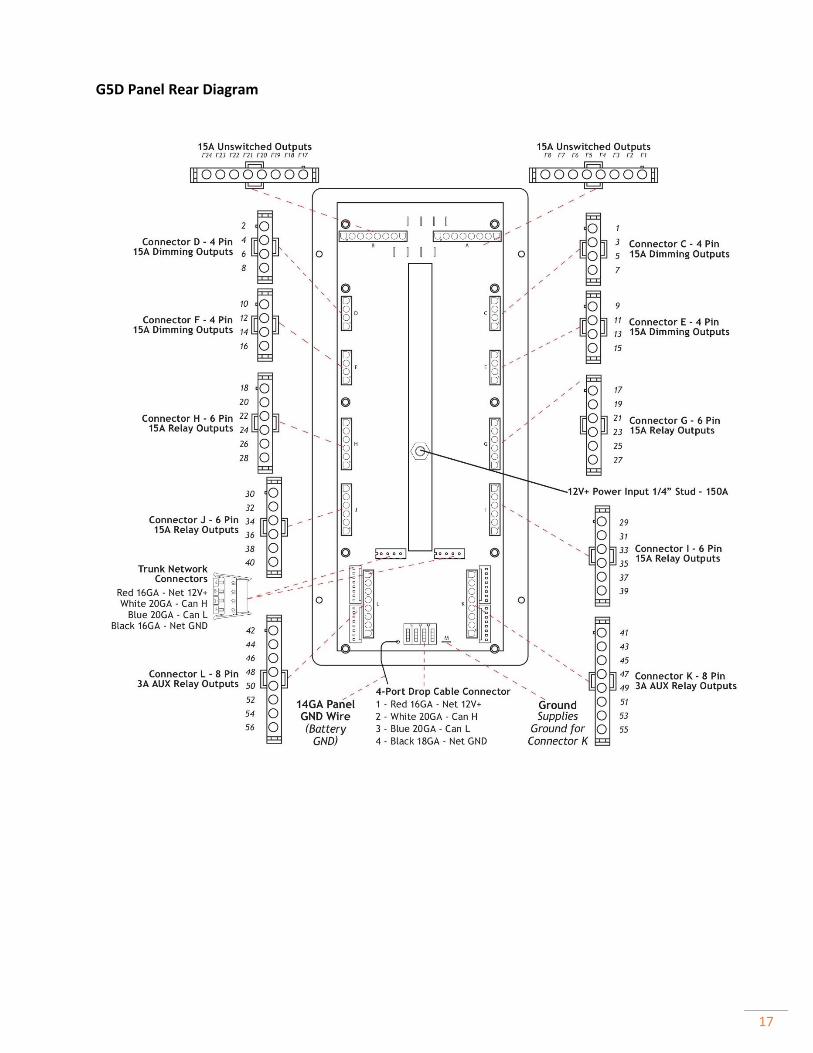
17
G5D Panel Rear Diagram
18
A LIGHT CIRCUIT/CHANNEL STAYS ON CONSTANTLY AND CANNOT BE TURNED OFF BY THE
SWITCH PANEL.
At the G5 control panel, check to see if the GREEN indicator LED for that circuit is constantly ON
even when the assigned switch is turned ON and OFF.
A LIGHT CIRCUIT/CHANNEL STAYS OFF CONSTANTLY AND CANNOT BE TURNED ON BY THE SWITCH
PANEL.
Press the ON button on the switch panel that controls the circuit in question. Does the status LED on
that button turn ON?
Always ON – Cycle the 12V Master Power OFF then ON. Note: Before pressing ANY switch panel
buttons, return to the G5 Panel and check the status of the LED for the circuit in question.
• If LED is still ON, unplug the assigned connector on the rear of the G5 for
the circuit/channel in question and test the voltage on the output.
- If the Green LED is still ON and the output is still ON, replace the G5 Panel. *
- If the Green LED is now OFF and there is no output voltage present, check the load
or the wiring between the G5 panel output and the load.
Now OFF – If the Green indicator LED turns On and OFF, verify the wiring to the load or the load
itself.
YES – Proceed to the G5 control panel and check the status of the indicator LED for that specific
fuse or circuit. What color is it?
• RED – Replace the fuse and verify if the circuit now works properly.
• Green – Check the voltage for the assigned pin/wire coming out of the assigned output
connector on the rear of the G5 panel.
- If there is voltage, check the wiring between the G5 panel and the load or the load
itself.
- If there is NO voltage, check for a loose or damaged fuse or fuse holder.
• NO LED Illuminated – RE-Verify the switch panel button LED is still ON and verify that you
are looking at the correct circuit on the G5 panel. If this checks out, replace the G5. *
NO – Verify that the switch panel and the G5 are online by looking at the status of the NET LEDs.
• NET LED is RED or RED/ORANGE – See the Network Troubleshooting Guide.
• Net LED’s are all SOLID GREEN – Remove the switch panel and plug it directly into the
front of the G5 NET PORT.
- If the LED indicator on the switch panel button DOES turn ON when the ON button
is pressed, proceed to the Network Troubleshooting Guide.
- If the LED indicator on the switch panel button still does not turn ON when the ON
button is pressed, replace the switch panel. *
19
A DIMMING LIGHT CIRCUIT/CHANNEL IS ALWAYS ON DIMLY.
Press and hold the ON button to see if the light gets brighter and then HOLD the OFF button to
see if the light gets dimmer. Next, press the OFF button to see if the light turns OFF.
• If lights are working as described above, everything is working properly.
• If the lights dim up and down but do not turn OFF, continue reading.
At the G5 control panel, check to see if the GREEN indicator LED for that circuit/channel is
constantly on, even when the assigned switch is turned ON and OFF.
LED ALWAYS ON – Cycle the 12V Master power OFF and ON. Before pressing any switch panel
buttons, return to the G5 panel and check the state of the GREEN indicator LED for the circuit in
question.
• If LED is still ON, unplug the connector on the rear of the G5 for the circuit/channel in
question and test the voltage on the output.
- If the GREEN LED is still ON and the output is still ON, replace the G5 panel. *
- If the GREEN LED is now OFF and there is no output voltage present, check the
load or the wiring between the G5 panel output and the load.
• If the LED is now OFF, return to the switch panel/button for the circuit in question and
verify it is now working.
If the GREEN indicator LED turns ON and OFF, verify the wiring to the load or the load itself.
20
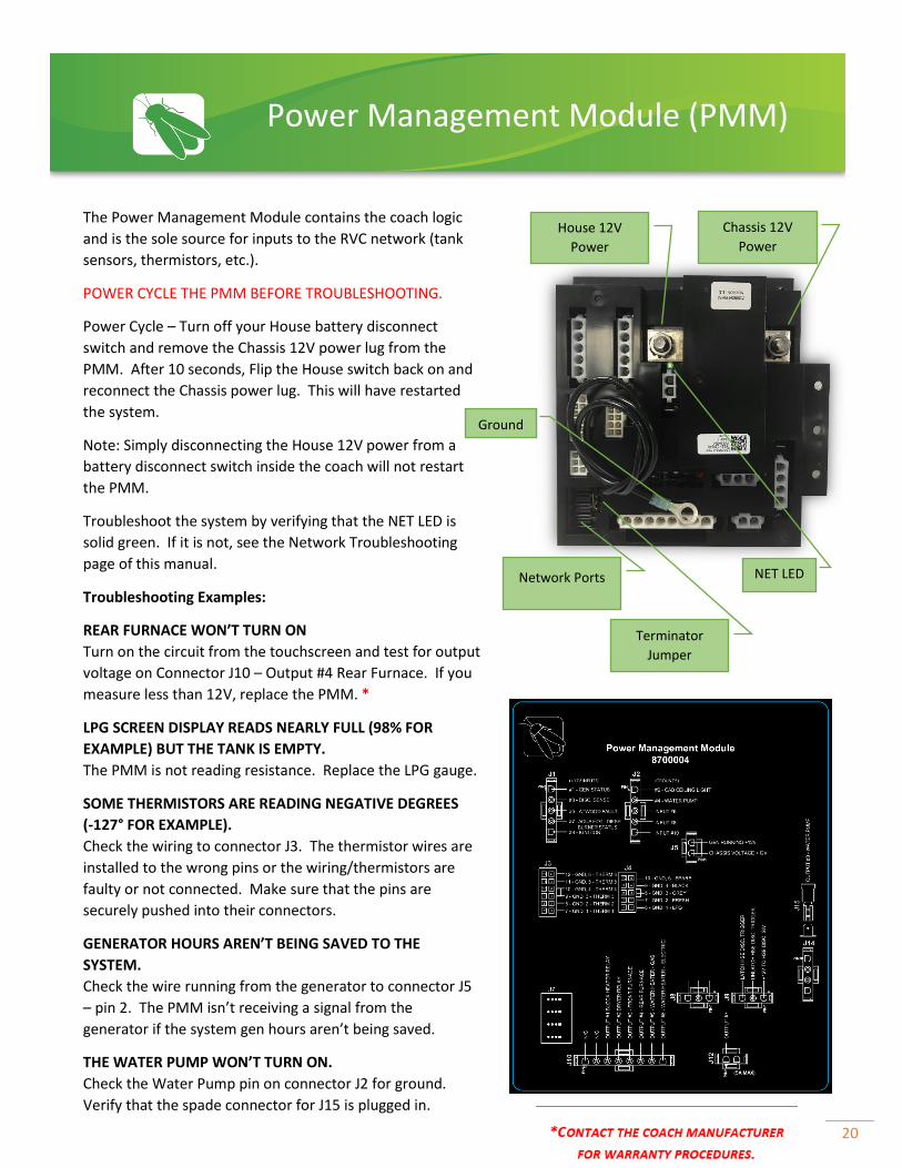
The Power Management Module contains the coach logic
and is the sole source for inputs to the RVC network (tank
sensors, thermistors, etc.).
POWER CYCLE THE PMM BEFORE TROUBLESHOOTING.
Power Cycle – Turn off your House battery disconnect
switch and remove the Chassis 12V power lug from the
PMM. After 10 seconds, Flip the House switch back on and
reconnect the Chassis power lug. This will have restarted
the system.
Note: Simply disconnecting the House 12V power from a
battery disconnect switch inside the coach will not restart
the PMM.
Troubleshoot the system by verifying that the NET LED is
solid green. If it is not, see the Network Troubleshooting
page of this manual.
Troubleshooting Examples:
REAR FURNACE WON’T TURN ON
Turn on the circuit from the touchscreen and test for output
voltage on Connector J10 – Output #4 Rear Furnace. If you
measure less than 12V, replace the PMM. *
LPG SCREEN DISPLAY READS NEARLY FULL (98% FOR
EXAMPLE) BUT THE TANK IS EMPTY.
The PMM is not reading resistance. Replace the LPG gauge.
SOME THERMISTORS ARE READING NEGATIVE DEGREES
(-127° FOR EXAMPLE).
Check the wiring to connector J3. The thermistor wires are
installed to the wrong pins or the wiring/thermistors are
faulty or not connected. Make sure that the pins are
securely pushed into their connectors.
GENERATOR HOURS AREN’T BEING SAVED TO THE
SYSTEM.
Check the wire running from the generator to connector J5
– pin 2. The PMM isn’t receiving a signal from the
generator if the system gen hours aren’t being saved.
THE WATER PUMP WON’T TURN ON.
Check the Water Pump pin on connector J2 for ground.
Verify that the spade connector for J15 is plugged in.
Power Management Module (PMM)
House 12V
Power
NET LED
Terminator
Jumper
Chassis 12V
Power
Network Ports
Ground

21
Terminator Jumper
If you are experiencing network issues and are not measuring 60
ohms when you measure network resistance, check the
terminator jumper. If this jumper is on the wrong 2 pins, this will
cause the network resistance to double. For example, a healthy
network that measures 60 ohms with 2 active terminators, will
measure 120 ohms of resistance if this terminator becomes
disabled.
Enabled
Disabled

22
Address Chart (Connector J2)
Address Dip In 1 Dip In 2
1 Open Open
2 Ground Open
3 Open Ground
4 Ground Ground
AirCon Module
NET LED
The AirCon Module is designed to interface with air
conditioning units in RV applications to allow them to
be controlled via RV-C.
AirCons use relays to control the 120v power that
goes to the compressors, fans, reverse valve, and heat
strip in the AC unit. They also connect to the freeze
sense inside the AC unit to be able to monitor the
status and intelligently handle defrost cycling.
Up to four AirCons can be used on a single network.
Each AirCon will need to be addressed individually on
connector J2. See the table below for address
settings.
Troubleshooting
AN AIR CONDITIONING UNIT IS TURNING ON WITH
AN AC REQUEST FROM A DIFFERENT ZONE.
The AirCon has probably been addressed incorrectly.
See the chart below for addressing details.
AN AIR CONDITIONER SHUTS DOWN AFTER
APPROXIMATELY 30 SECONDS.
Make sure that the freeze sensor is installed correctly
or replace the freeze sensor if necessary.
AN AIR CONDITIONER WILL NOT FUNCTION, BUT THE
SCREEN SHOWS THAT IT IS CURRENTLY ON.
Check to make sure that the NET LED is solid green. If
not, check the network wire running to the AirCon.
Check to make sure that 120v power has been ran to
the AirCon and that it is hooked up correctly.
Make sure that the AC override toggle switch is in the
correct position.
23
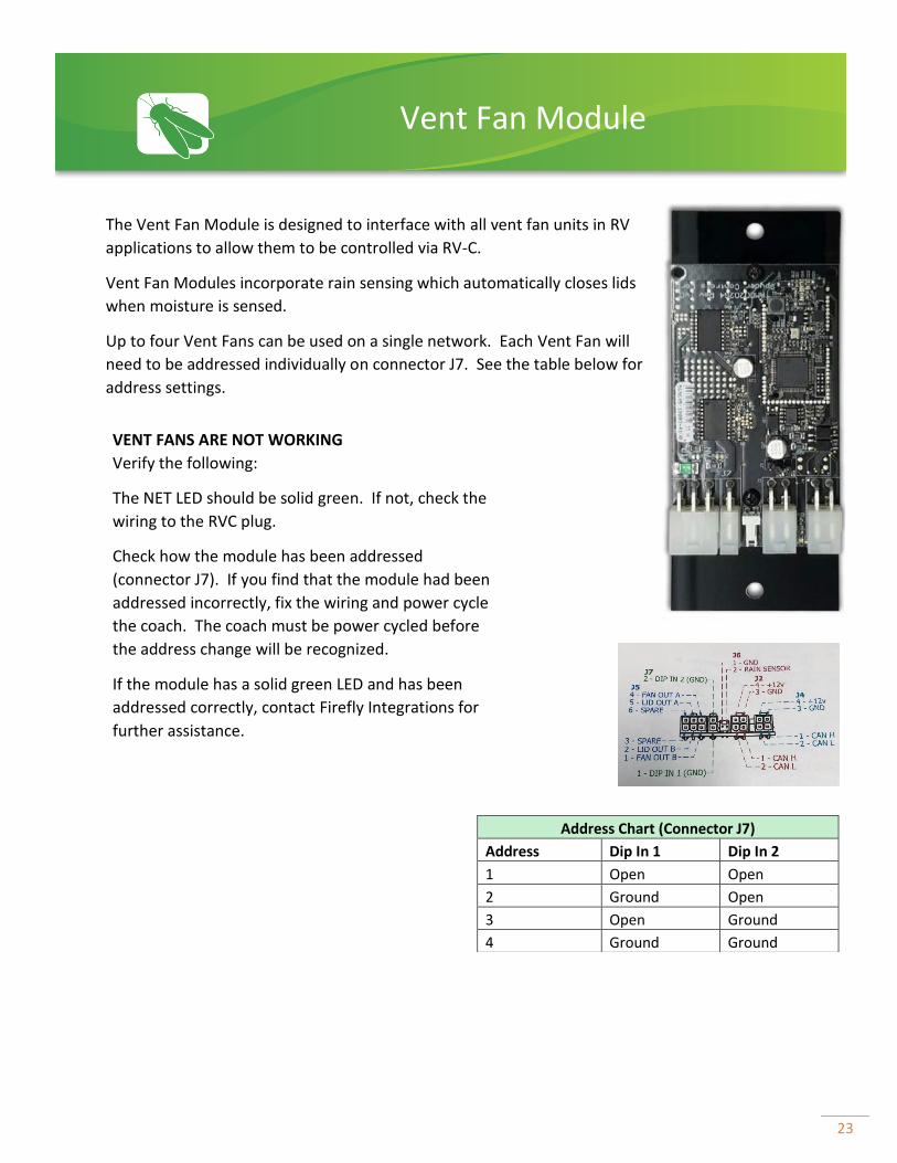
The Vent Fan Module is designed to interface with all vent fan units in RV
applications to allow them to be controlled via RV-C.
Vent Fan Modules incorporate rain sensing which automatically closes lids
when moisture is sensed.
Up to four Vent Fans can be used on a single network. Each Vent Fan will
need to be addressed individually on connector J7. See the table below for
address settings.
Address Chart (Connector J7)
Address Dip In 1 Dip In 2
1 Open Open
2 Ground Open
3 Open Ground
4 Ground Ground
Vent Fan Module
VENT FANS ARE NOT WORKING
Verify the following:
The NET LED should be solid green. If not, check the
wiring to the RVC plug.
Check how the module has been addressed
(connector J7). If you find that the module had been
addressed incorrectly, fix the wiring and power cycle
the coach. The coach must be power cycled before
the address change will be recognized.
If the module has a solid green LED and has been
addressed correctly, contact Firefly Integrations for
further assistance.
24
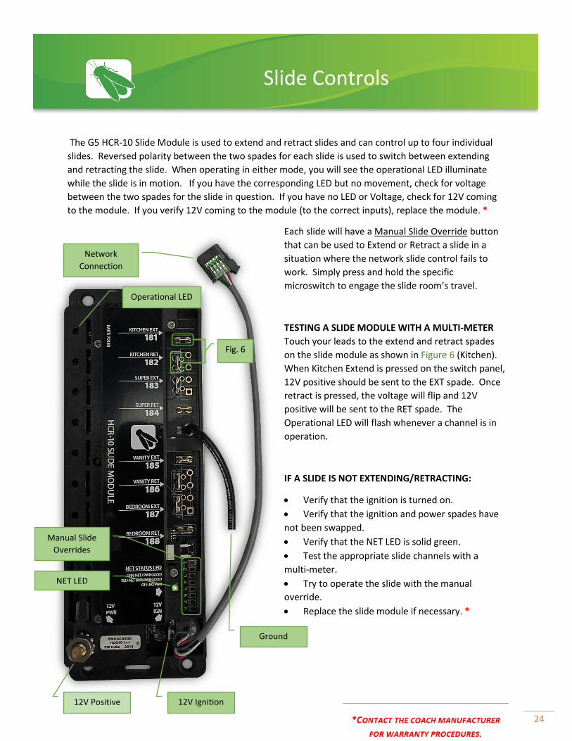
The G5 HCR-10 Slide Module is used to extend and retract slides and can control up to four individual
slides. Reversed polarity between the two spades for each slide is used to switch between extending
and retracting the slide. When operating in either mode, you will see the operational LED illuminate
while the slide is in motion. If you have the corresponding LED but no movement, check for voltage
between the two spades for the slide in question. If you have no LED or Voltage, check for 12V coming
to the module. If you verify 12V coming to the module (to the correct inputs), replace the module. *
Each slide will have a Manual Slide Override button
that can be used to Extend or Retract a slide in a
situation where the network slide control fails to
work. Simply press and hold the specific
microswitch to engage the slide room’s travel.
TESTING A SLIDE MODULE WITH A MULTI-METER
Touch your leads to the extend and retract spades
on the slide module as shown in Figure 6 (Kitchen).
When Kitchen Extend is pressed on the switch panel,
12V positive should be sent to the EXT spade. Once
retract is pressed, the voltage will flip and 12V
positive will be sent to the RET spade. The
Operational LED will flash whenever a channel is in
operation.
IF A SLIDE IS NOT EXTENDING/RETRACTING:
• Verify that the ignition is turned on.
• Verify that the ignition and power spades have
not been swapped.
• Verify that the NET LED is solid green.
• Test the appropriate slide channels with a
multi-meter.
• Try to operate the slide with the manual
override.
• Replace the slide module if necessary. *
Slide Controls
12V Positive 12V Ignition
Manual Slide
Overrides
Ground
Network
Connection
z
NET LED
Operational LED
Fig. 6
25
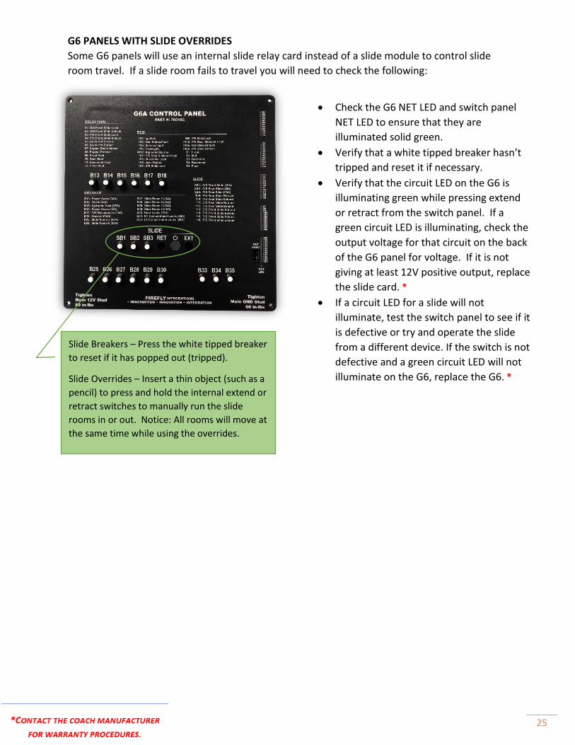
G6 PANELS WITH SLIDE OVERRIDES
Some G6 panels will use an internal slide relay card instead of a slide module to control slide
room travel. If a slide room fails to travel you will need to check the following:
Slide Breakers – Press the white tipped breaker
to reset if it has popped out (tripped).
Slide Overrides – Insert a thin object (such as a
pencil) to press and hold the internal extend or
retract switches to manually run the slide
rooms in or out. Notice: All rooms will move at
the same time while using the overrides.
• Check the G6 NET LED and switch panel
NET LED to ensure that they are
illuminated solid green.
• Verify that a white tipped breaker hasn’t
tripped and reset it if necessary.
• Verify that the circuit LED on the G6 is
illuminating green while pressing extend
or retract from the switch panel. If a
green circuit LED is illuminating, check the
output voltage for that circuit on the back
of the G6 panel for voltage. If it is not
giving at least 12V positive output, replace
the slide card. *
• If a circuit LED for a slide will not
illuminate, test the switch panel to see if it
is defective or try and operate the slide
from a different device. If the switch is not
defective and a green circuit LED will not
illuminate on the G6, replace the G6. *
26
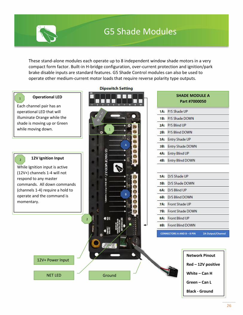
These stand-alone modules each operate up to 8 independent window shade motors in a very compact form factor. Built-in H-bridge configuration, over-current protection and ignition/park brake disable inputs are standard features. G5 Shade Control modules can also be used to operate other medium-current motor loads that require reverse polarity type outputs.
G5 Shade Modules
Operational LED
Each channel pair has an
operational LED that will
illuminate Orange while the
shade is moving up or Green
while moving down.
12V Ignition Input
While Ignition input is active
(12V+) channels 1-4 will not
respond to any master
commands. All down commands
(channels 1-4) require a hold to
operate and the command is
momentary.
CONNECTORS A AND B – 8 PIN 2A Output/Channel
NET LED
2
12V+ Power Input
2
A
B
Ground
SHADE MODULE A
Part #7000050
Network Pinout
Red – 12V positive
White – Can H
Green – Can L
Black - Ground
1
1
27
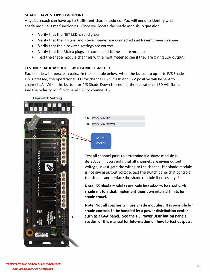
SHADES HAVE STOPPED WORKING.
A typical coach can have up to 3 different shade modules. You will need to identify which
shade module is malfunctioning. Once you locate the shade module in question:
• Verify that the NET LED is solid green.
• Verify that the Ignition and Power spades are connected and haven’t been swapped.
• Verify that the dipswitch settings are correct
• Verify that the Molex plugs are connected to the shade module.
• Test the shade module channels with a multimeter to see if they are giving 12V output
TESTING SHADE MODULES WITH A MULTI-METER.
Each shade will operate in pairs. In the example below, when the button to operate P/S Shade
Up is pressed, the operational LED for channel 1 will flash and 12V positive will be sent to
channel 1A. When the button for P/S Shade Down is pressed, the operational LED will flash,
and the polarity will flip to send 12V to channel 1B.
Multi-
meter
Test all channel pairs to determine if a shade module is
defective. If you verify that all channels are giving output
voltage, investigate the wiring to the shades. If a shade module
is not giving output voltage, test the switch panel that controls
the shades and replace the shade module if necessary. *
Note: G5 shade modules are only intended to be used with
shade motors that implement their own internal limits for
shade travel.
Note: Not all coaches will use Shade modules. It is possible for
shade controls to be handled by a power distribution center
such as a G6A panel. See the DC Power Distribution Panels
section of this manual for information on how to test outputs.
28
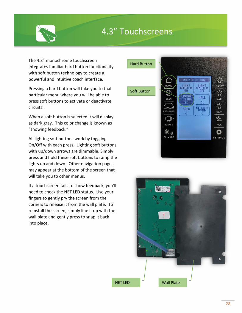
The 4.3” monochrome touchscreen
integrates familiar hard button functionality
with soft button technology to create a
powerful and intuitive coach interface.
Pressing a hard button will take you to that
particular menu where you will be able to
press soft buttons to activate or deactivate
circuits.
When a soft button is selected it will display
as dark gray. This color change is known as
“showing feedback.”
All lighting soft buttons work by toggling
On/Off with each press. Lighting soft buttons
with up/down arrows are dimmable. Simply
press and hold these soft buttons to ramp the
lights up and down. Other navigation pages
may appear at the bottom of the screen that
will take you to other menus.
If a touchscreen fails to show feedback, you’ll
need to check the NET LED status. Use your
fingers to gently pry the screen from the
corners to release it from the wall plate. To
reinstall the screen, simply line it up with the
wall plate and gently press to snap it back
into place.
4.3” Touchscreens
Hard Button
Soft Button
NET LED
Wall Plate

29
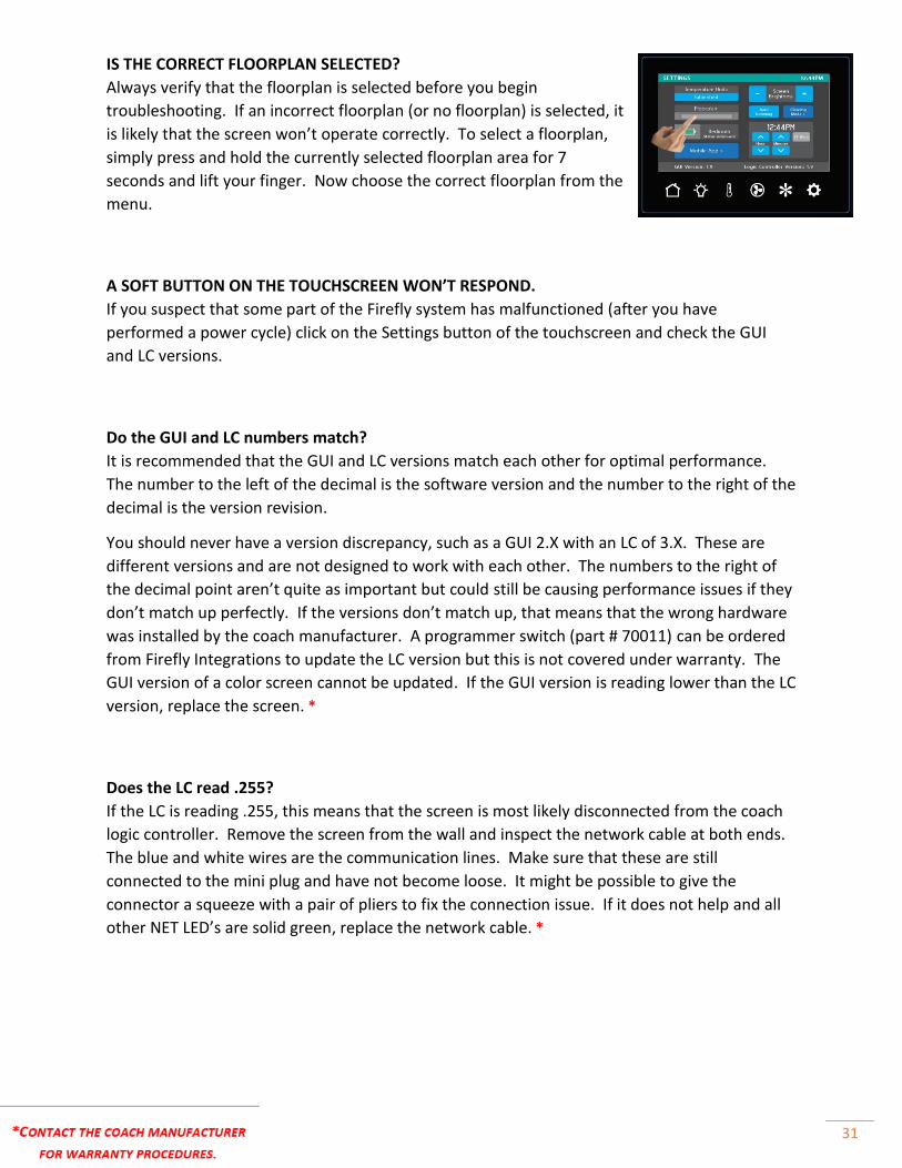
IS THE CORRECT FLOORPLAN SELECTED?
Always verify that the floorplan is selected before you begin troubleshooting. If an incorrect
floorplan (or no floorplan) is selected, it is likely that the screen won’t operate correctly. To
select a floorplan (from the settings screen), simply press and hold the currently selected
floorplan area for 7 seconds and lift your finger. Now choose the correct floorplan from the
menu.
A SOFT BUTTON ON THE TOUCHSCREEN WON’T RESPOND.
If you suspect that some part of the Firefly system has
malfunctioned (after you have performed a power cycle) click
on the Settings button of the touchscreen and check the GUI
and LC versions.
Do the GUI and LC numbers match?
It is recommended that the GUI and LC versions match each
other for optimal performance. The number to the left of the
decimal is the software version and the number to the right of
the decimal is the version revision.
You should never have a version discrepancy, such as a GUI 2.X
with an LC of 3.X. These are different versions and are not
designed to work with each other. The numbers to the right of
the decimal point aren’t quite as important but could still be
causing performance issues if they don’t match up perfectly.
If the versions don’t match up, that means that the wrong
hardware was installed by the coach manufacturer. A
programmer switch (part # 70011) can be ordered from Firefly
Integrations to rectify the situation but this is not covered under
warranty. (GUI, LC, Make, Model, Serial # and problem description
required when ordering.)
Does the LC read .255?
If the LC is reading .255, this means that the screen is most likely
disconnected from the coach logic controller. Remove the screen
from the wall and inspect the network cable at both ends. The
blue and white wires are the communication lines. Make sure that these
are still connected to the mini plug and have not become loose. It might
be possible to give the connector a squeeze with a pair of pliers to fix the
connection issue. If it does not help, replace the network cable. *
NOTE: NEVER START TROUBLESHOOTING UNTIL ALL RELATED NET LED’S ARE CHECKED.
If any NET LED status is anything other than SOLID GREEN please refer to the network
troubleshooting page.
Software Versions
Back of switch

30
The 7” Spectrum touchscreen uses only soft buttons to
control all functions of the system.
The row of navigation buttons at the bottom of the
screen will transport you from menu to menu with the
press of a button.
When a soft button is selected it will display as blue.
This color change is known as “showing feedback.”
All lighting soft buttons work by toggling On/Off with
each press. Lighting soft buttons with up/down arrows
are dimmable. Simply press and hold these soft buttons
to ramp the lights up and down.
If a touchscreen fails to show feedback, you’ll need to
check the NET LED status. The Net LED is located on
the back of the touchscreen. To remove the screen
from the wall, place your fingers along the top edge of
the screen and press down while pulling the screen
towards you at the same time. This will release the
touchscreen from the wall. Be sure not to drop it once
it releases from the wall. To reinstall the screen, simply
line it up with the wall plate and snap it back into place.
7” Spectrum Touchscreens
Navigation Buttons
Soft Buttons
NET LED
31
IS THE CORRECT FLOORPLAN SELECTED?
Always verify that the floorplan is selected before you begin
troubleshooting. If an incorrect floorplan (or no floorplan) is selected, it
is likely that the screen won’t operate correctly. To select a floorplan,
simply press and hold the currently selected floorplan area for 7
seconds and lift your finger. Now choose the correct floorplan from the
menu.
A SOFT BUTTON ON THE TOUCHSCREEN WON’T RESPOND.
If you suspect that some part of the Firefly system has malfunctioned (after you have
performed a power cycle) click on the Settings button of the touchscreen and check the GUI
and LC versions.
Do the GUI and LC numbers match?
It is recommended that the GUI and LC versions match each other for optimal performance.
The number to the left of the decimal is the software version and the number to the right of the
decimal is the version revision.
You should never have a version discrepancy, such as a GUI 2.X with an LC of 3.X. These are
different versions and are not designed to work with each other. The numbers to the right of
the decimal point aren’t quite as important but could still be causing performance issues if they
don’t match up perfectly. If the versions don’t match up, that means that the wrong hardware
was installed by the coach manufacturer. A programmer switch (part # 70011) can be ordered
from Firefly Integrations to update the LC version but this is not covered under warranty. The
GUI version of a color screen cannot be updated. If the GUI version is reading lower than the LC
version, replace the screen. *
Does the LC read .255?
If the LC is reading .255, this means that the screen is most likely disconnected from the coach
logic controller. Remove the screen from the wall and inspect the network cable at both ends.
The blue and white wires are the communication lines. Make sure that these are still
connected to the mini plug and have not become loose. It might be possible to give the
connector a squeeze with a pair of pliers to fix the connection issue. If it does not help and all
other NET LED’s are solid green, replace the network cable. *
32
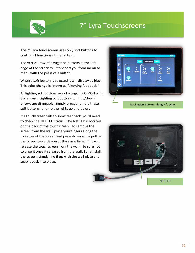
The 7” Lyra touchscreen uses only soft buttons to
control all functions of the system.
The vertical row of navigation buttons at the left
edge of the screen will transport you from menu to
menu with the press of a button.
When a soft button is selected it will display as blue.
This color change is known as “showing feedback.”
All lighting soft buttons work by toggling On/Off with
each press. Lighting soft buttons with up/down
arrows are dimmable. Simply press and hold these
soft buttons to ramp the lights up and down.
If a touchscreen fails to show feedback, you’ll need
to check the NET LED status. The Net LED is located
on the back of the touchscreen. To remove the
screen from the wall, place your fingers along the
top edge of the screen and press down while pulling
the screen towards you at the same time. This will
release the touchscreen from the wall. Be sure not
to drop it once it releases from the wall. To reinstall
the screen, simply line it up with the wall plate and
snap it back into place.
7” Lyra Touchscreens
NET LED
Navigation Buttons along left edge.

33
Vegatouch is a state-of-the-art coach control
interface which allows the user to easily monitor
and control many major systems in the coach.
Vegatouch screens come in 10” and 7” models.
Many of our Vegatouch systems integrate with
Crestron to incorporate A/V control, as well as
mobile coach control with smart devices.
VERIFY THE CURRENTLY SELECTED FLOORPLAN AND OPTIONS BEFORE TROUBLESHOOTING.
Press and hold the Question Mark for 7 seconds to enter the Vegatouch software versions screen.
Tap just inside of each corner on the Vegatouch logo (one at a time) to make hidden navigation
tabs appear on the left side of the screen.
Vegatouch Touchscreens
Current Tab
Software Versions

34
Inverters - Displays information from your Inverters.
Generator - Tap +/- to adjust the Generator hours saved to the system or tap Reset to set the hours to
zero.
AGS - Tap +/- to set your desired AGS values.
Prev. Hidden
1
1
2
2
3
3

35
Mode Selector- Choose tech mode for faster operation. Choose production mode before you’re finished
working on the coach.
Year Selector- Choose the desired year (version) of Vegatouch for the coach.
Model Selector- Choose Anthem or Cornerstone.
Floorplan- Choose the appropriate coach floorplan.
Reverse Slide Controls- Check the box if you need a slide to reverse direction.
Misc. Options- It is recommended to select Defaults for Inverter and AGS defaults.
The “Other” tab contains tools for troubleshooting screen hardware and software, generally in a bench
environment.
The “Uploader” tab will only be used when replacing the Vegatouch screen with a newer version. Please
see the Vegatouch Replacement Guide for more information.
4
1
3 6
5
2
1
2
3
4
5
6
7
7
8
8
36
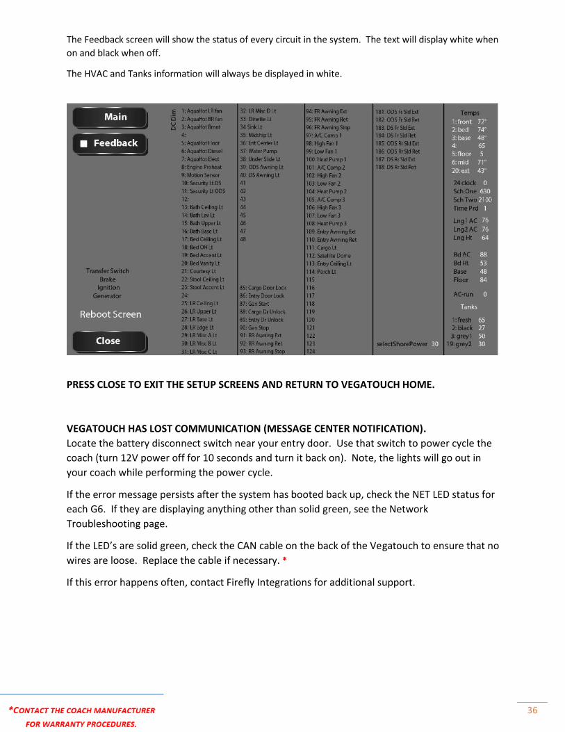
The Feedback screen will show the status of every circuit in the system. The text will display white when
on and black when off.
The HVAC and Tanks information will always be displayed in white.
PRESS CLOSE TO EXIT THE SETUP SCREENS AND RETURN TO VEGATOUCH HOME.
VEGATOUCH HAS LOST COMMUNICATION (MESSAGE CENTER NOTIFICATION).
Locate the battery disconnect switch near your entry door. Use that switch to power cycle the
coach (turn 12V power off for 10 seconds and turn it back on). Note, the lights will go out in
your coach while performing the power cycle.
If the error message persists after the system has booted back up, check the NET LED status for
each G6. If they are displaying anything other than solid green, see the Network
Troubleshooting page.
If the LED’s are solid green, check the CAN cable on the back of the Vegatouch to ensure that no
wires are loose. Replace the cable if necessary. *
If this error happens often, contact Firefly Integrations for additional support.
37
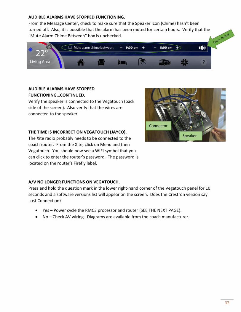
AUDIBLE ALARMS HAVE STOPPED FUNCTIONING.
From the Message Center, check to make sure that the Speaker Icon (Chime) hasn’t been
turned off. Also, it is possible that the alarm has been muted for certain hours. Verify that the
“Mute Alarm Chime Between” box is unchecked.
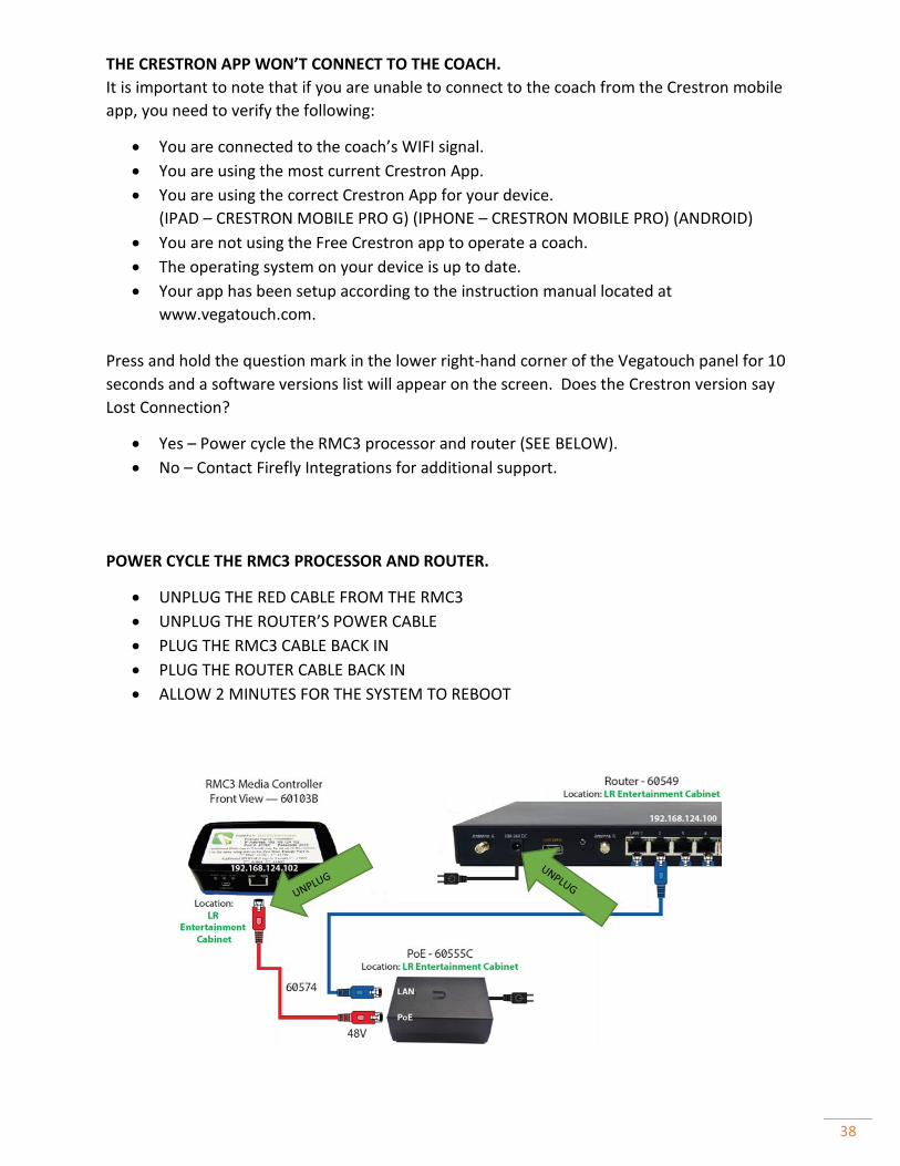
AUDIBLE ALARMS HAVE STOPPED
FUNCTIONING…CONTINUED.
Verify the speaker is connected to the Vegatouch (back
side of the screen). Also verify that the wires are
connected to the speaker.
THE TIME IS INCORRECT ON VEGATOUCH (JAYCO).
The Xite radio probably needs to be connected to the
coach router. From the Xite, click on Menu and then
Vegatouch. You should now see a WIFI symbol that you
can click to enter the router’s password. The password is
located on the router’s Firefly label.
A/V NO LONGER FUNCTIONS ON VEGATOUCH.
Press and hold the question mark in the lower right-hand corner of the Vegatouch panel for 10
seconds and a software versions list will appear on the screen. Does the Crestron version say
Lost Connection?
• Yes – Power cycle the RMC3 processor and router (SEE THE NEXT PAGE).
• No – Check AV wiring. Diagrams are available from the coach manufacturer.
Speaker
Connector
38
THE CRESTRON APP WON’T CONNECT TO THE COACH.
It is important to note that if you are unable to connect to the coach from the Crestron mobile
app, you need to verify the following:
• You are connected to the coach’s WIFI signal.
• You are using the most current Crestron App.
• You are using the correct Crestron App for your device.
(IPAD – CRESTRON MOBILE PRO G) (IPHONE – CRESTRON MOBILE PRO) (ANDROID)
• You are not using the Free Crestron app to operate a coach.
• The operating system on your device is up to date.
• Your app has been setup according to the instruction manual located at
www.vegatouch.com.
Press and hold the question mark in the lower right-hand corner of the Vegatouch panel for 10
seconds and a software versions list will appear on the screen. Does the Crestron version say
Lost Connection?
• Yes – Power cycle the RMC3 processor and router (SEE BELOW).
• No – Contact Firefly Integrations for additional support.
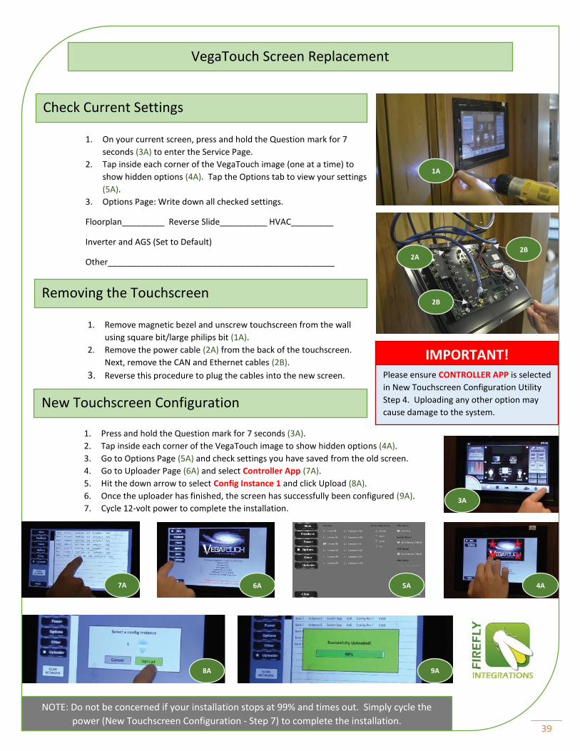
POWER CYCLE THE RMC3 PROCESSOR AND ROUTER.
• UNPLUG THE RED CABLE FROM THE RMC3
• UNPLUG THE ROUTER’S POWER CABLE
• PLUG THE RMC3 CABLE BACK IN
• PLUG THE ROUTER CABLE BACK IN
• ALLOW 2 MINUTES FOR THE SYSTEM TO REBOOT
39
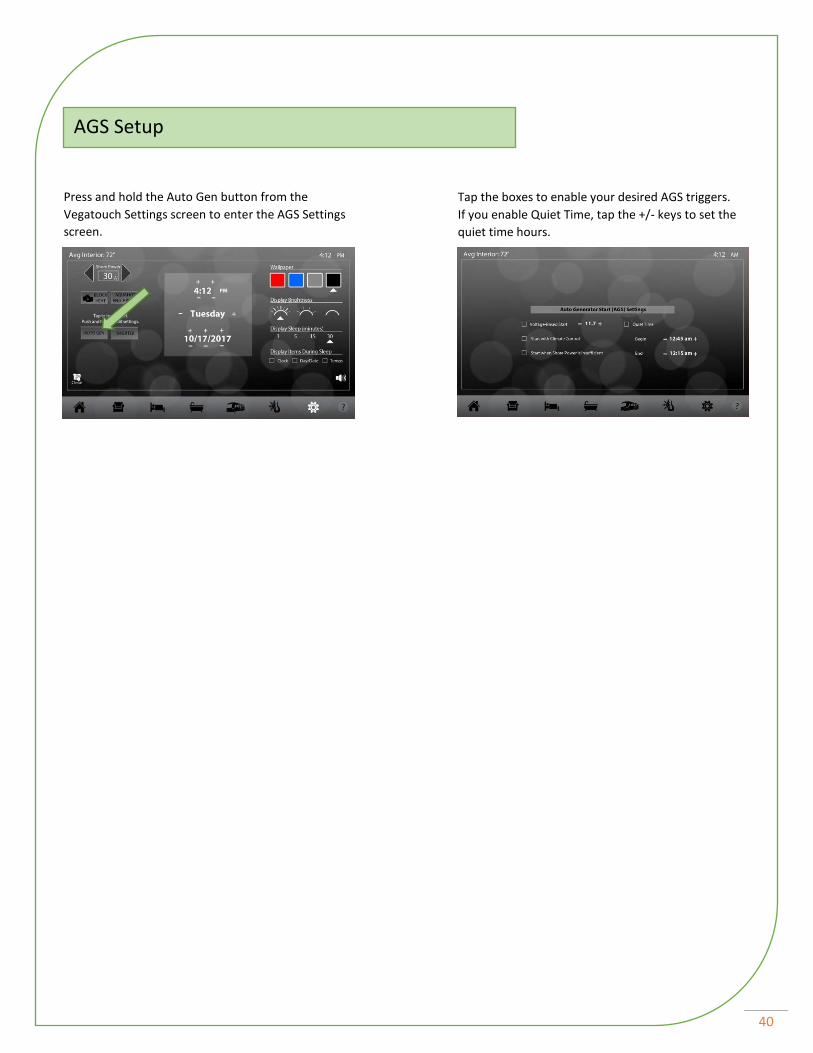
1. On your current screen, press and hold the Question mark for 7
seconds (3A) to enter the Service Page.
2. Tap inside each corner of the VegaTouch image (one at a time) to
show hidden options (4A). Tap the Options tab to view your settings
(5A).
3. Options Page: Write down all checked settings.
Floorplan_________ Reverse Slide__________ HVAC_________
Inverter and AGS (Set to Default)
Other________________________________________________
1. Remove magnetic bezel and unscrew touchscreen from the wall
using square bit/large philips bit (1A).
2. Remove the power cable (2A) from the back of the touchscreen.
Next, remove the CAN and Ethernet cables (2B).
3. Reverse this procedure to plug the cables into the new screen.
1. Press and hold the Question mark for 7 seconds (3A).
2. Tap inside each corner of the VegaTouch image to show hidden options (4A).
3. Go to Options Page (5A) and check settings you have saved from the old screen.
4. Go to Uploader Page (6A) and select Controller App (7A).
5. Hit the down arrow to select Config Instance 1 and click Upload (8A).
6. Once the uploader has finished, the screen has successfully been configured (9A).
7. Cycle 12-volt power to complete the installation.
VegaTouch Screen Replacement
Check Current Settings
Removing the Touchscreen
IMPORTANT! Please ensure CONTROLLER APP is selected
in New Touchscreen Configuration Utility
Step 4. Uploading any other option may
cause damage to the system. New Touchscreen Configuration
1A
2A
2B
2B
3A
4A 5A 6A 7A
8A 9A
NOTE: Do not be concerned if your installation stops at 99% and times out. Simply cycle the
power (New Touchscreen Configuration - Step 7) to complete the installation.
40
Press and hold the Auto Gen button from the
Vegatouch Settings screen to enter the AGS Settings
screen.
Tap the boxes to enable your desired AGS triggers.
If you enable Quiet Time, tap the +/- keys to set the
quiet time hours.
AGS Setup
41
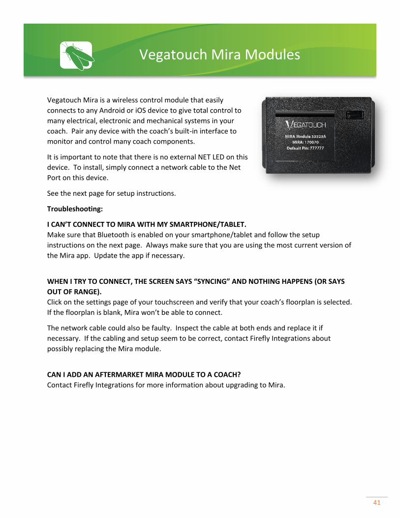
Vegatouch Mira is a wireless control module that easily
connects to any Android or iOS device to give total control to
many electrical, electronic and mechanical systems in your
coach. Pair any device with the coach’s built-in interface to
monitor and control many coach components.
It is important to note that there is no external NET LED on this
device. To install, simply connect a network cable to the Net
Port on this device.
See the next page for setup instructions.
Troubleshooting:
I CAN’T CONNECT TO MIRA WITH MY SMARTPHONE/TABLET.
Make sure that Bluetooth is enabled on your smartphone/tablet and follow the setup
instructions on the next page. Always make sure that you are using the most current version of
the Mira app. Update the app if necessary.
WHEN I TRY TO CONNECT, THE SCREEN SAYS “SYNCING” AND NOTHING HAPPENS (OR SAYS
OUT OF RANGE).
Click on the settings page of your touchscreen and verify that your coach’s floorplan is selected.
If the floorplan is blank, Mira won’t be able to connect.
The network cable could also be faulty. Inspect the cable at both ends and replace it if
necessary. If the cabling and setup seem to be correct, contact Firefly Integrations about
possibly replacing the Mira module.
CAN I ADD AN AFTERMARKET MIRA MODULE TO A COACH?
Contact Firefly Integrations for more information about upgrading to Mira.
Vegatouch Mira Modules
42
Notice: Make sure that Bluetooth is turned ON on your smart device
settings before proceeding.
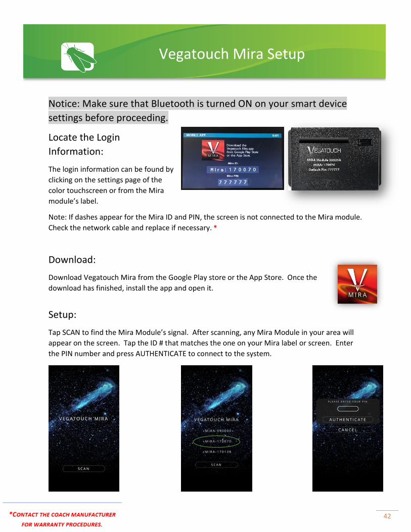
Locate the Login
Information:
The login information can be found by
clicking on the settings page of the
color touchscreen or from the Mira
module’s label.
Note: If dashes appear for the Mira ID and PIN, the screen is not connected to the Mira module.
Check the network cable and replace if necessary. *
Download:
Download Vegatouch Mira from the Google Play store or the App Store. Once the
download has finished, install the app and open it.
Setup:
Tap SCAN to find the Mira Module’s signal. After scanning, any Mira Module in your area will
appear on the screen. Tap the ID # that matches the one on your Mira label or screen. Enter
the PIN number and press AUTHENTICATE to connect to the system.
Vegatouch Mira Setup
43
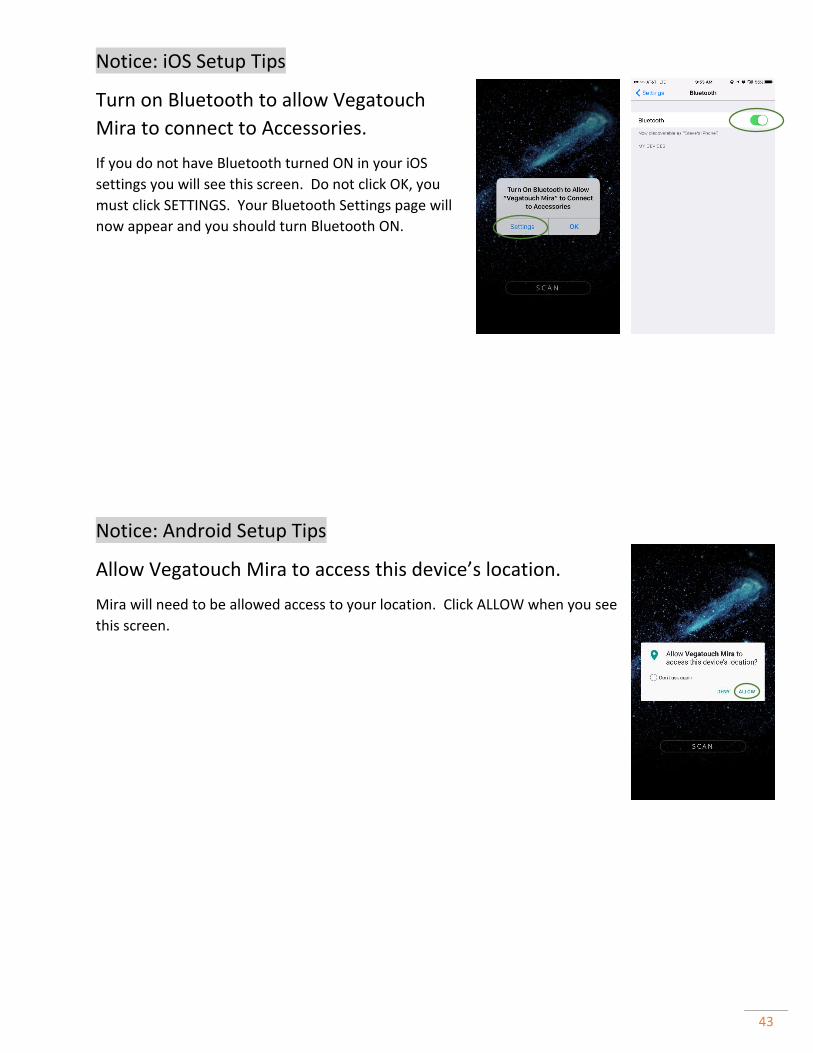
Notice: iOS Setup Tips
Turn on Bluetooth to allow Vegatouch
Mira to connect to Accessories.
If you do not have Bluetooth turned ON in your iOS
settings you will see this screen. Do not click OK, you
must click SETTINGS. Your Bluetooth Settings page will
now appear and you should turn Bluetooth ON.
Notice: Android Setup Tips
Allow Vegatouch Mira to access this device’s location.
Mira will need to be allowed access to your location. Click ALLOW when you see
this screen.

44
App Settings:
Access the App Settings page by pressing the Gear icon on the App Navigation Bar.
Tap to set your own personalized
Bluetooth pin to eliminate the chance
of another Mira owner accidentally
controlling your module.
Tap to disconnect your device from Mira.
Tapping Reset Device will completely restart the Module and
reconnect once it has powered back up.
Tapping Update Config will force a download of the config from
the cloud.

45
Vegatouch Pluto is a wireless control module that
easily connects to any Android or iOS device to give
total control to many electrical, electronic and
mechanical systems in your coach. Pair any device
with the coach’s built-in interface to monitor and
control many components.
It is important to note that there is no external NET
LED on this device. To install the hardware, simply
connect a network cable to the Net Port on this device.
Pluto connects to your phone via WIFI. To setup Pluto, simply connect your phone to Pluto’s
WIFI signal (just as you would at a WIFI hotspot) and enter the pin located on the MOBILE APP
page.
MY PHONE SHOWS AN IMAGE OF PLUTO AND SAYS “DOWNLOAD COMPLETE”
BUT NOTHING HAPPENS.
If you see this image, you are not currently connected to Pluto’s WIFI. Open your
phone’s WIFI settings and try connecting again.
THE CONNECTION SCREEN ONLY SHOWS DASHES.
If only dashes display for the login info, Pluto is not currently connected to the network. Check
the network drop cable connections from the Pluto module to the network. Replace the cable
if necessary. *
Download the FREE Vegatouch Pluto App from the APP STORE or GOOGLE PLAY.
Vegatouch Pluto
NET PORT
46
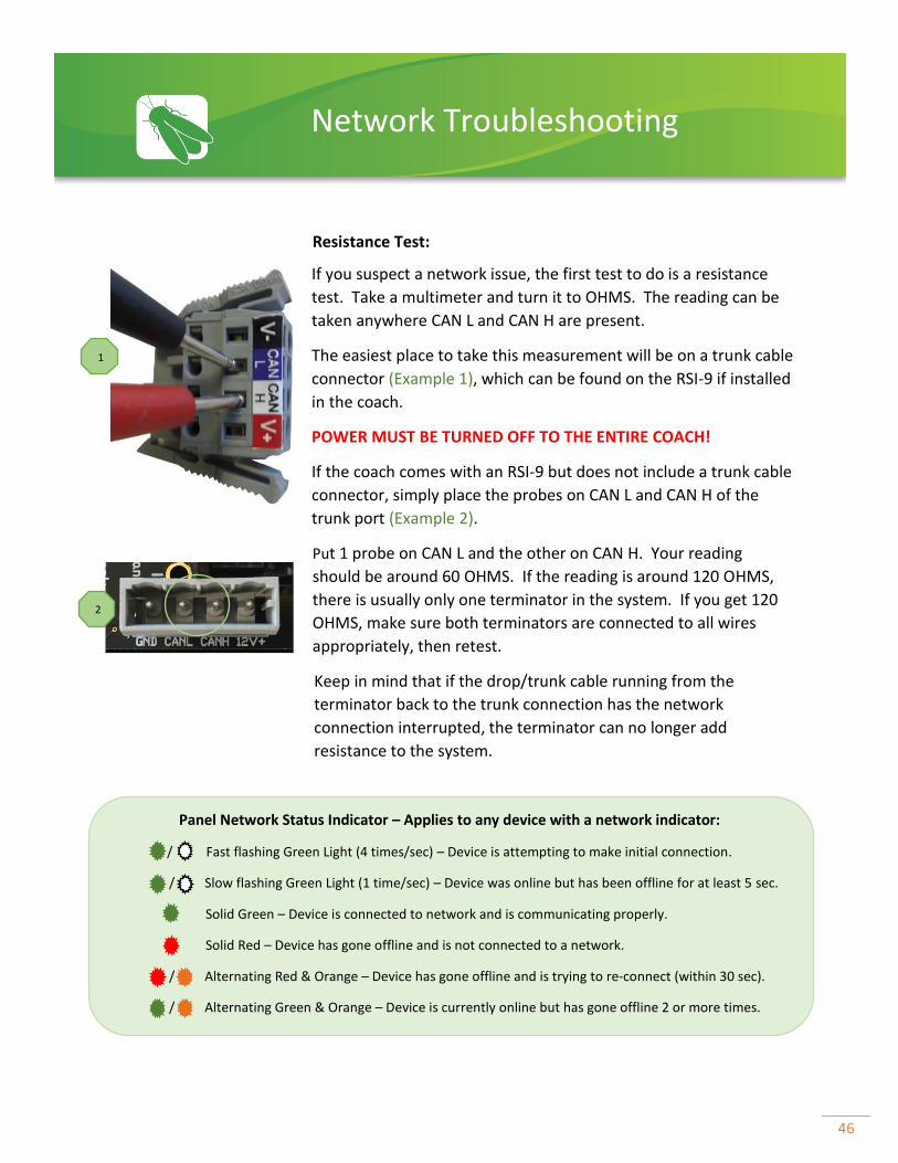
If you suspect a network issue, the first test to do is a resistance
test. Take a multimeter and turn it to OHMS. The reading can be
taken anywhere CAN L and CAN H are present.
The easiest place to take this measurement will be on a trunk cable
connector (Example 1), which can be found on the RSI-9 if installed
in the coach.
POWER MUST BE TURNED OFF TO THE ENTIRE COACH!
If the coach comes with an RSI-9 but does not include a trunk cable
connector, simply place the probes on CAN L and CAN H of the
trunk port (Example 2).
Put 1 probe on CAN L and the other on CAN H. Your reading
should be around 60 OHMS. If the reading is around 120 OHMS,
there is usually only one terminator in the system. If you get 120
OHMS, make sure both terminators are connected to all wires
appropriately, then retest.
Keep in mind that if the drop/trunk cable running from the
terminator back to the trunk connection has the network
connection interrupted, the terminator can no longer add
resistance to the system.
Panel Network Status Indicator – Applies to any device with a network indicator:
/ Fast flashing Green Light (4 times/sec) – Device is attempting to make initial connection.
/ Slow flashing Green Light (1 time/sec) – Device was online but has been offline for at least 5 sec.
Solid Green – Device is connected to network and is communicating properly.
Solid Red – Device has gone offline and is not connected to a network.
/ Alternating Red & Orange – Device has gone offline and is trying to re-connect (within 30 sec).
/ Alternating Green & Orange – Device is currently online but has gone offline 2 or more times.
1
2
Network Troubleshooting
Resistance Test:
47
NOTE: It is very helpful to have an accurate Network Wiring Diagram (NWD) to follow while
troubleshooting network wiring issues. These are available from Firefly Integrations.
All devices (switch panels and control panels/modules) instantly go offline (SOLID RED) as
soon as the network is powered up.
Verify all CAN network measurements (as outlined above) at various points throughout the network.
• CAN H and CAN L voltage measurements out of range.
- This is usually caused by a short to 12V, ground or between CAN H and CAN L. Begin isolating
parts of the trunk and drop cable to locate the issue.
- Various devices on the network can also be unplugged to follow the process of elimination to
determine if there is a specific device causing the problem.
Carefully check each of the connectors at every drop tap and device to verify the proper wire
order/pinout as listed above.
- A pair of CAN H and CAN L wires in the wrong order on the connector will cause devices to go
offline even though the network measurements will be in the proper range.
Multiple devices go offline over a period of time or whenever there is significant network
activity (i.e. – Light Master or Shades Master buttons are pressed).
Intermittent network performance is typically caused by one or more of the following:
- Drop cables that exceed the 20ft drop length from the main trunk line.
- Improper installation or location of the network terminators.
- Poor grounds on devices that are not network powered located throughout the coach (not
using the same ground as the Network powered components).
- Use of non-CAN specification network cable.
- Voltage loss at the ends of the network due to poor connections, improper power supply,
low battery voltage or excessive trunk or drop cable lengths.
A single device does not connect or goes offline in the installed location but works when
plugged directly into the NET PORT on the front of your DC Panel.
Verify the drop cable connector/termination for that specific location using the connector diagrams and
network measurements shown above.
Check for a damaged drop cable or drop tap for that location.

48
Technical Support is available Monday – Friday, 7:30am – 5:00pm EST.
Firefly Integrations
1013 Elroy Drive
Middlebury, Indiana 46540
Phone: (574) 825-4600 Option 1
www.fireflyintegrations.com
Follow us on Facebook @Fireflyintegrations
Technical Support
49
WARRANTY PROCEDURES
Please contact your coach Manufacturer for their specific warranty procedures.