version 1 - data.emotion-tech.comµdelta_originale/documentation... · introduction - printed parts...
TRANSCRIPT
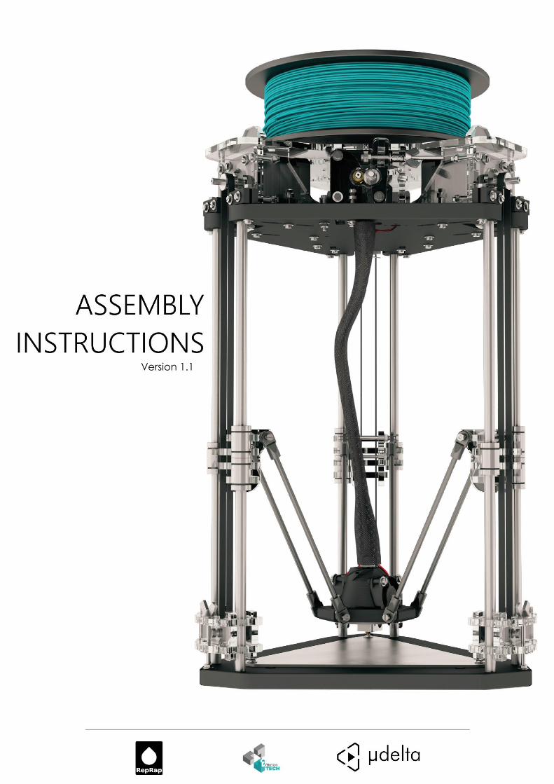
Version 1.1
Introduction - Printed parts 2
Introduction
Designers :
Hugo Flye [email protected] Thomas Batigne [email protected] Antony Soury [email protected]
Photographic credits :
Pictures and 3D representations made by eMotion Tech http://www.emotion-tech.com Picture director: Antony Soury
Authors:
eMotion Tech – http://www.Reprap-France.com Loïc Déchaseaux [email protected] Antony Soury [email protected] Hugo Flye [email protected] Thomas Batigne [email protected]
Sources :
http://reprap.org/wiki/RepRap
http://www.repetier.com/
License :
µDelta: CC BY-NC-SA 4.0
This document: CC BY-NC-SA 4.0
http://creativecommons.org/licenses/by-nc-sa/4.0/
Update:
Last update : 25/06/2014
Links:
Reprap community: http://reprap.org/wiki/RepRap
Repetier-Host: http://www.repetier.com/
3D models database: http://www.thingiverse.com/
- Printed parts 3
Introduction ........................................................................................................................................................ 2
µDelta introduction ............................................................................................................................................ 5
Safety instructions .............................................................................................................................................. 7
Assembly ............................................................................................................................................................. 8
Bill of materials ................................................................................................................................................... 9
A. Printed parts .......................................................................................................................................... 9
B. Acrylic parts ........................................................................................................................................... 9
1. Tensioner .................................................................................................................................... 9
2. Slider ........................................................................................................................................... 9
3. Motor holder .............................................................................................................................. 9
4. Extruder ...................................................................................................................................... 9
C. Smooth rods and connecting rods ....................................................................................................... 10
D. Mechanical parts ................................................................................................................................. 10
A. Screws, nuts and washers .................................................................................................................... 10
B. Electronics ............................................................................................................................................ 11
C. Additional parts ................................................................................................................................... 11
D. Hexagon kit .......................................................................................................................................... 12
A. Options ................................................................................................................................................ 12
Tools ................................................................................................................................................................. 13
Mechanical assembly ....................................................................................................................................... 14
A. Bottom assembly ................................................................................................................................. 14
1. Inferior frame ........................................................................................................................... 14
2. Tensioner .................................................................................................................................. 15
3. Sliders ....................................................................................................................................... 20
B. Top assembly ....................................................................................................................................... 23
1. Motor holder assembly ............................................................................................................ 23
2. Superior frame fixation ............................................................................................................ 31
3. Extruder assembly .................................................................................................................... 33
C. Belt positioning. ................................................................................................................................... 37
Core 40
A. Core assembly ...................................................................................................................................... 40
B. LED (optional) ...................................................................................................................................... 48
C. Connecting rods positioning. ............................................................................................................... 49
Finishing ............................................................................................................................................................ 51
Electronics assembly ........................................................................................................................................ 56
A. Teensylu ............................................................................................................................................... 56
B. Connections ......................................................................................................................................... 57
4. Stepsticks .................................................................................................................................. 58

- Printed parts 4
5. Endstops ................................................................................................................................... 59
6. Motors ...................................................................................................................................... 60
7. Cartridge heater. ...................................................................................................................... 61
8. Thermistor ................................................................................................................................ 61
9. Fans .......................................................................................................................................... 61
10. USB and power supply.............................................................................................................. 62
Annex 1: Spool holder ...................................................................................................................................... 63
A. Assembly .............................................................................................................................................. 63
B. Connections ......................................................................................................................................... 65
µDelta introduction - Printed parts 5
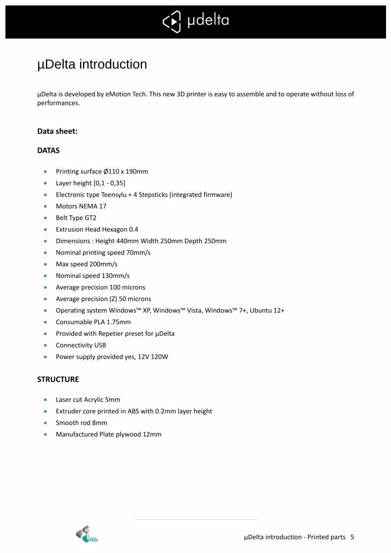
µDelta introduction
µDelta is developed by eMotion Tech. This new 3D printer is easy to assemble and to operate without loss of performances.
Data sheet:
DATAS
Printing surface Ø110 x 190mm
Layer height [0,1 - 0,35]
Electronic type Teensylu + 4 Stepsticks (integrated firmware)
Motors NEMA 17
Belt Type GT2
Extrusion Head Hexagon 0.4
Dimensions : Height 440mm Width 250mm Depth 250mm
Nominal printing speed 70mm/s
Max speed 200mm/s
Nominal speed 130mm/s
Average precision 100 microns
Average precision (Z) 50 microns
Operating system Windows™ XP, Windows™ Vista, Windows™ 7+, Ubuntu 12+
Consumable PLA 1.75mm
Provided with Repetier preset for µDelta
Connectivity USB
Power supply provided yes, 12V 120W
STRUCTURE
Laser cut Acrylic 5mm
Extruder core printed in ABS with 0.2mm layer height
Smooth rod 8mm
Manufactured Plate plywood 12mm

µDelta introduction - Printed parts 6
ERGONOMY Easy to mount: A 3D printer kit with an intuitive assembly
Simple electronic, no soldering
Easy wiring and assembly
Belt adjustment with ergonomic belt tensioners Easy to calibrate: A simplified software
Fully software calibration
Pre-configured open-source software (no firmware upload required, Repetier Host and Slic3r pre-configured)
Easy to maintain
Quick height adjustment with the software
OPTIMISATION AND UPGRADE You can improve the µDelta by adding the following option (soon available on eMotion Tech website):
Spool holder with fan
LCD screen controller to print without computer
Lighting with circular LED
Heated bed
Safety instructions - Printed parts 7
Safety instructions
General safety instructions ALWAYS HAVE ADULT SUPERVISON WHEN USING THE PRINTER. The nozzle can reach 270°C, TO AVOID BURNING, DO NOT TOUCH THE NOZZLE WHILE THE PRINTER IS WORKING. KEEP THE PRINTER AWAY FROM CHILDREN AND ANIMALS. OPERATE IN A VENTILATED ROOM. Plastic fumes effects are not known. In case of use in a closed room we recommend the use of an extractor fan.
The addition of protections is your responsibility. Safety can be improved by:
An emergency stop button
Housing protection
Smoke detector
CE marking µDelta is a 3D printer kit. It includes all the parts you need for assembling but does not include additional protections. Electrical safety. The power supply provided is labelled CE. The Power supply is protected against short-circuit and do not need any modifications. The µDelta operate at voltage of 12V and is not concerned by the low voltage directive.
Further information Information above are not exhaustive. We used sources of information we consider as reliable. However, we cannot guarantee that all these information are true and complete. We assume no liability for loses, injuries or damages due to assembly, transporting, storage, use, assembly, transporting or removal of the product.

- Printed parts 8
Assembly

Bill of materials - Printed parts 9
Bill of materials
A. Printed parts
1x Core
12x rod clamp
1x filament guide
B. Acrylic parts
Acrylic parts can be covered with protection and it may remain pieces of plastic. Remove it before use
We provide additional parts.
1. Tensioner 2. Slider
6x eM 1 6x eM 2
6x eM 3 6x eM 4 6x eM 5
3. Motor holder 4. Extruder
3x eM 7 6x eM 6 2x eM 8 1x eM 9 1x eM 10
2x eM 11 1x eM 12 1x eM 13

Bill of materials - Smooth rods and connecting rods 10
C. Smooth rods and
connecting rods
D. Mechanical parts
6x Ø8x400mm smooth rod
9x Linear bearing
1x Spring
6x Connecting rod
3x 624 ball bearing
1x 604 ball bearing
1x drive wheel
3x GT2 Belt
3x GT2 Pulley
A. Screws, nuts and washers
6x M3x10mm screw
14x M3x20mm screw
20x M3x25mm screw
15x M3x30mm screw
11x M3x50mm screw
4x M4x25mm screw
6x M2.5x16mm screw
3x Wood screw
61x M3 nut
4x M3 wing nut
8x M4 nut
6x M2.5 nut
76x Ø3mm washer
7x Ø4mm small washer
5x Ø4mm big washer
1x M4 Nylstop nut
8x M3 grub screw
We provide more Screws nuts and washer than necessary.
Bill of materials - Electronics 11
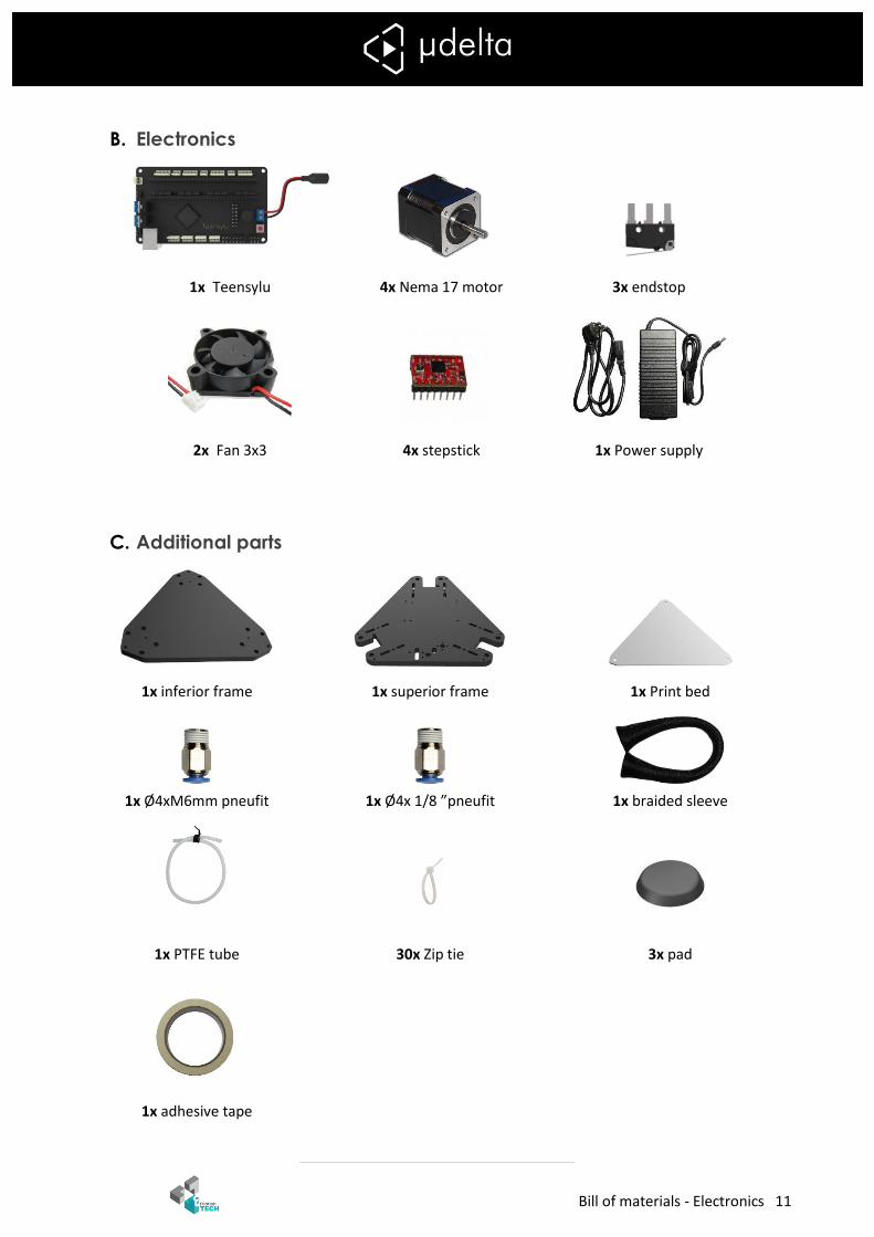
B. Electronics
1x Teensylu
4x Nema 17 motor
3x endstop
2x Fan 3x3
4x stepstick
1x Power supply
C. Additional parts
1x inferior frame 1x superior frame 1x Print bed
1x Ø4xM6mm pneufit 1x Ø4x 1/8 ”pneufit 1x braided sleeve
1x PTFE tube 30x Zip tie 3x pad
1x adhesive tape
Bill of materials - Hexagon kit 12
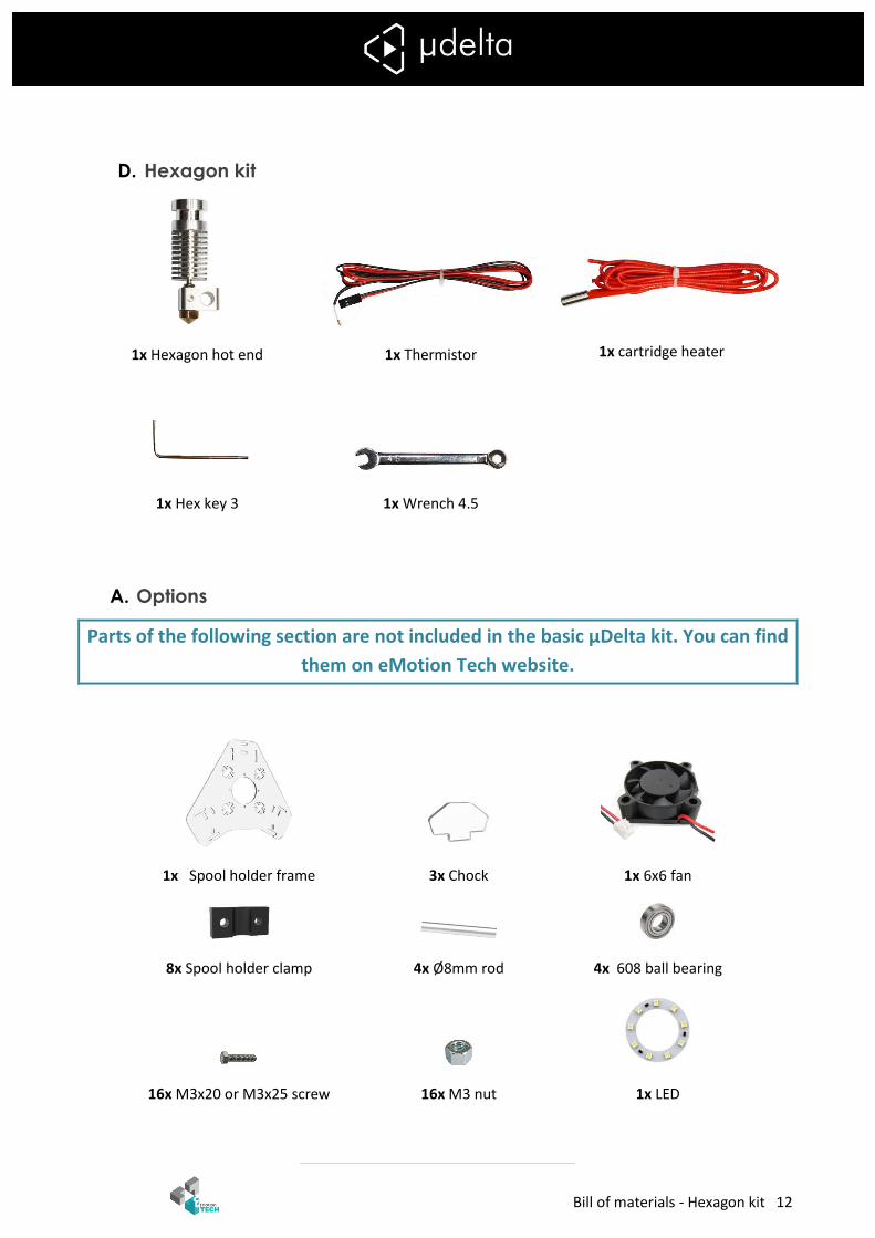
D. Hexagon kit
1x Hexagon hot end
1x Thermistor
1x cartridge heater
1x Hex key 3
1x Wrench 4.5
A. Options
Parts of the following section are not included in the basic µDelta kit. You can find
them on eMotion Tech website.
1x Spool holder frame
3x Chock
1x 6x6 fan
8x Spool holder clamp
4x Ø8mm rod
4x 608 ball bearing
16x M3x20 or M3x25 screw
16x M3 nut
1x LED
Tools - Options 13
Tools
Mallet
Slot screw driver
Philips screw driver
ceramic screwdriver
Wrench 5,5 and 7
Wrench 4,5(provided)
Hex key (provided)
Long nose pliers
Cutting pliers
utility knife
Meter
Mechanical assembly - Bottom assembly 14
Mechanical assembly
A. Bottom assembly
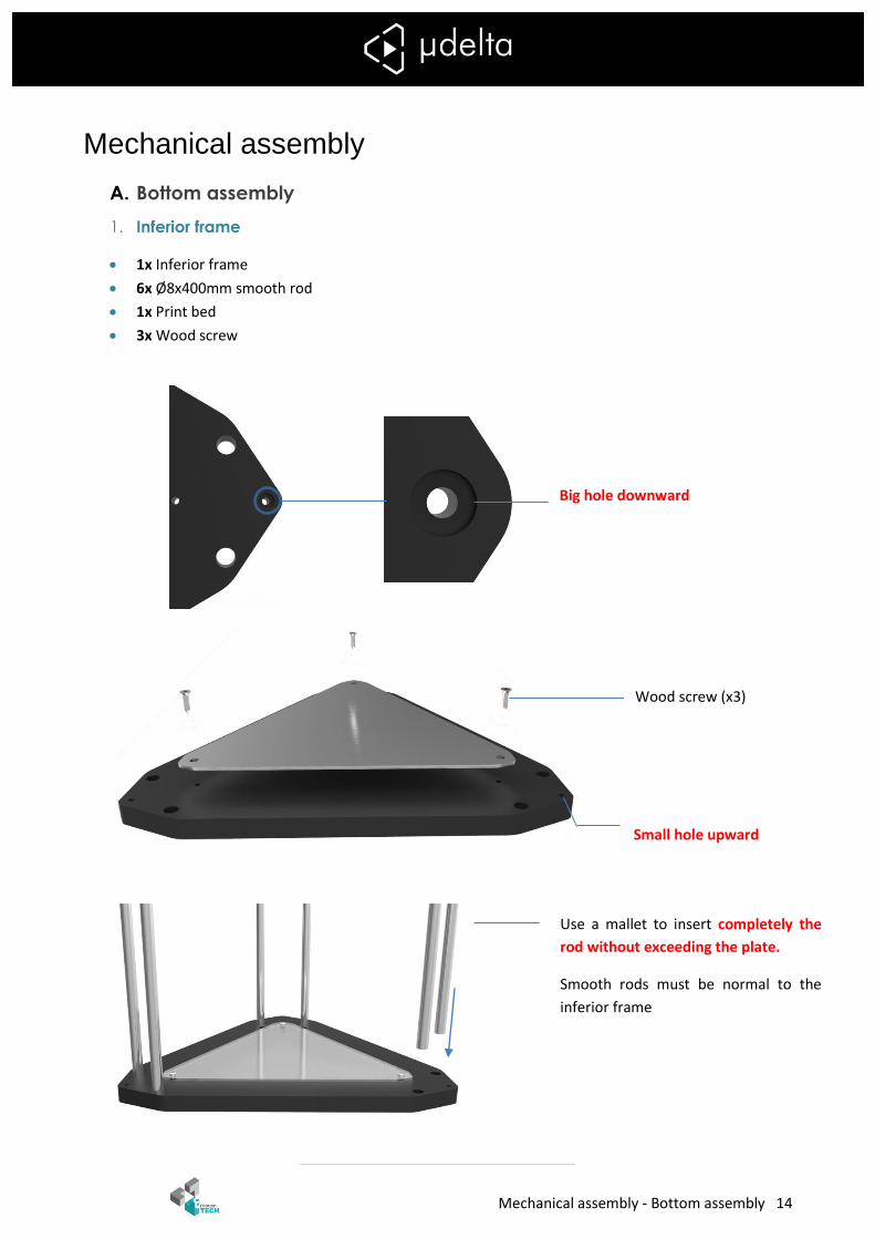
1. Inferior frame
1x Inferior frame
6x Ø8x400mm smooth rod
1x Print bed
3x Wood screw
Wood screw (x3)
Use a mallet to insert completely the
rod without exceeding the plate.
Smooth rods must be normal to the
inferior frame
Big hole downward
Small hole upward

Mechanical assembly - Bottom assembly 15
2. Tensioner
6x eM1
6x eM2
3x 624 ball bearing
3x M3x50 screw
3x M4x25 screw
3x Ø3mm washer
3x Ø4mm big washer
6x Ø4mm small washer
3x M3 nut
6x M4 nut
Repeat this operation for each corners
M3 nut Tighten against the frame
Ø3 washer
M3x50 screw
Mechanical assembly - Bottom assembly 16
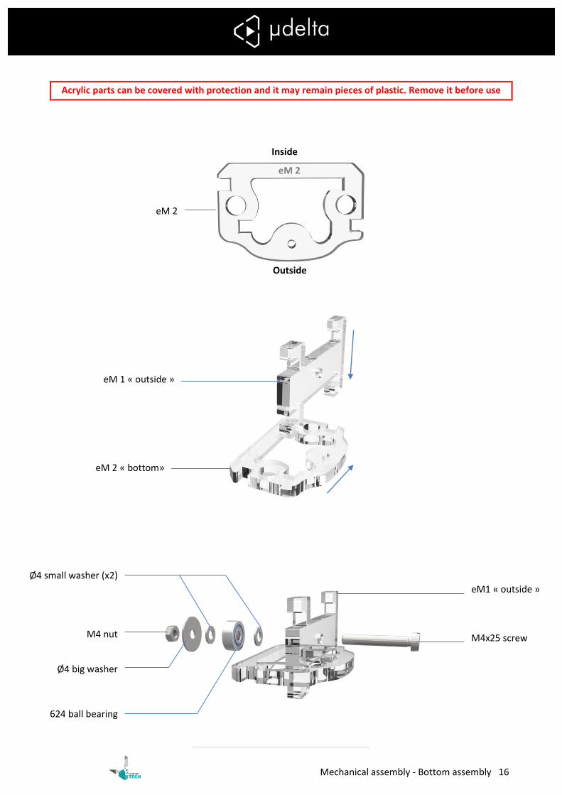
Acrylic parts can be covered with protection and it may remain pieces of plastic. Remove it before use
Inside
Outside
eM1 « outside »
M4x25 screw
Ø4 small washer (x2)
M4 nut
Ø4 big washer
624 ball bearing
eM 2
eM 2
eM 1 « outside »
eM 2 « bottom»
Mechanical assembly - Bottom assembly 17
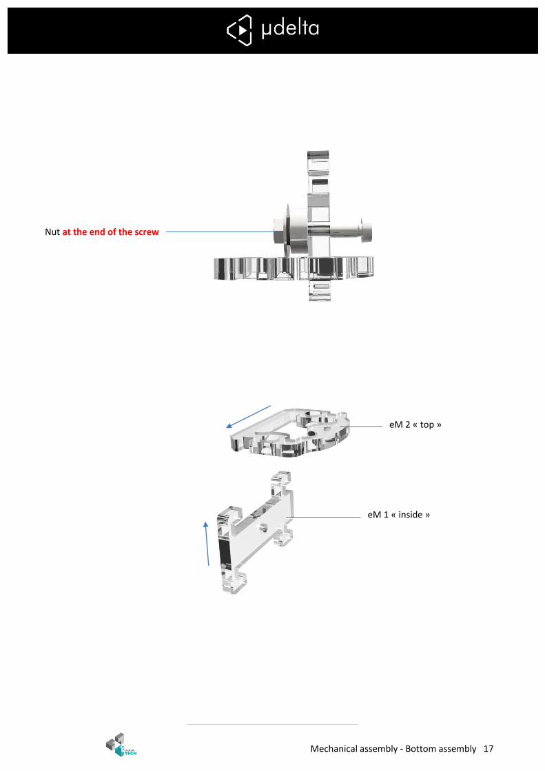
Nut at the end of the screw
eM 1 « inside »
eM 2 « top »
Mechanical assembly - Bottom assembly 18
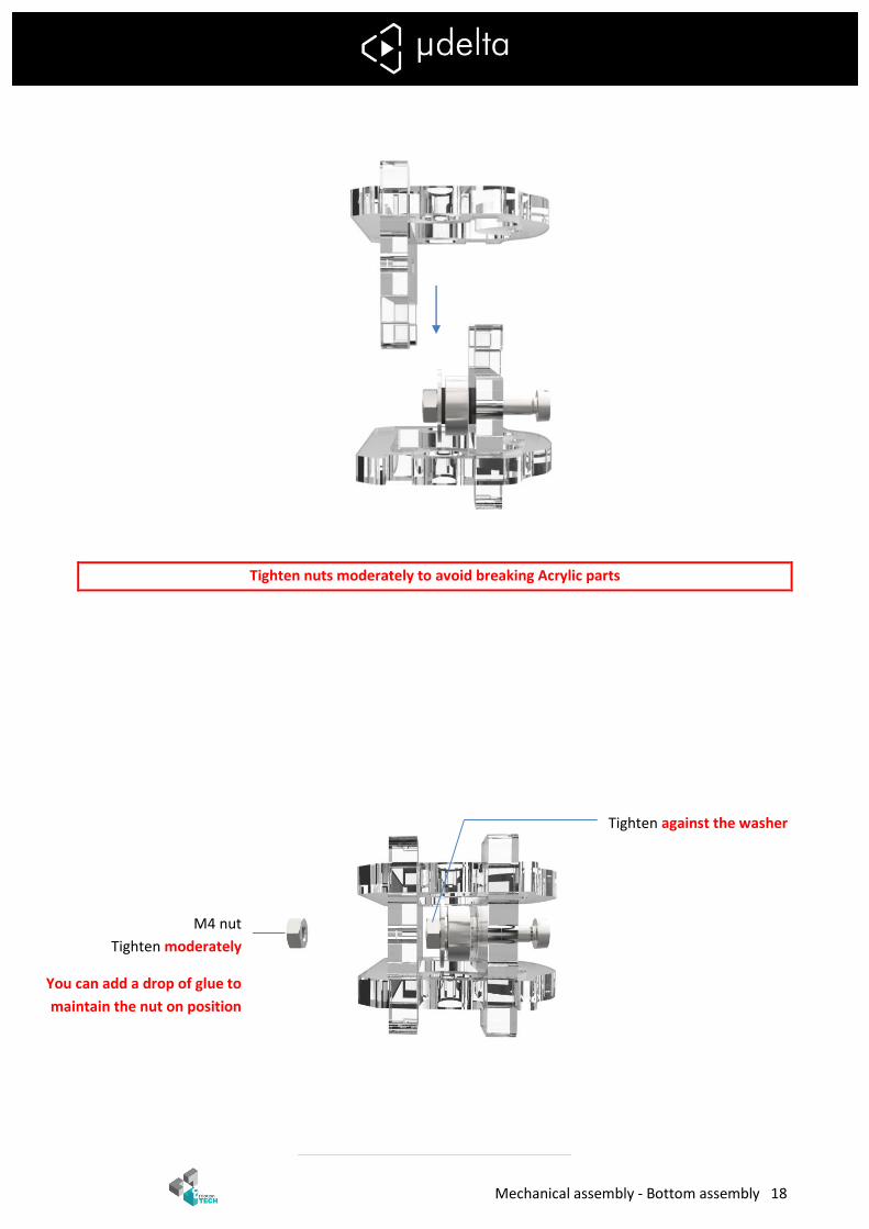
Tighten nuts moderately to avoid breaking Acrylic parts
M4 nut
Tighten moderately
You can add a drop of glue to
maintain the nut on position
Tighten against the washer
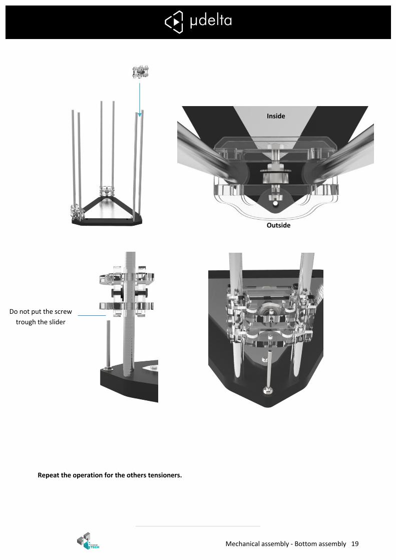
Mechanical assembly - Bottom assembly 19
Repeat the operation for the others tensioners.
Inside
Outside
Do not put the screw
trough the slider

Mechanical assembly - Bottom assembly 20
3. Sliders
6x eM3
6x eM4
6x eM5
12x Zip tie
9x Linear bearing
3x M3x30 screw
3x M3 nut
Assemble all sliders in the same way.
eM5
M3x30 screw M3 nut on the end of the screw
Up
Down
Inside Outside
Zip tie holes
eM
5
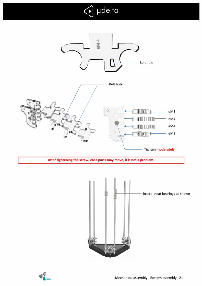
Mechanical assembly - Bottom assembly 21
After tightening the screw, eM3 parts may move, it is not a problem.
eM3
eM4
eM4
eM3
Belt hole
Belt hole
eM
4
Tighten moderately
Insert linear bearings as shown

Mechanical assembly - Bottom assembly 22
Insert a zip tie in each hole. Tighten the zip ties to fasten the slider.
The four fixations
must be on the same
side than the two
linear bearings
This bearing must be centered.
This bearing must not exceed the slider
Mechanical assembly - Top assembly 23
B. Top assembly
1. Motor holder assembly
3x eM7
6x eM6
1x Superior Frame
3x Nema 17 motor
3x GT2 pulley
3x Endstop
1x Ø4x 1/8 ”pneufit
12x Rod clamp
1x Filament guide
6x M2.5x16 screw
6x M3 grub screw
6x M3x10 screw
6x M3x20 screw
12x M3x25 screw
6x M3x30 screw
6x M2.5 nut
18x M3 nut
30x Ø3 washer
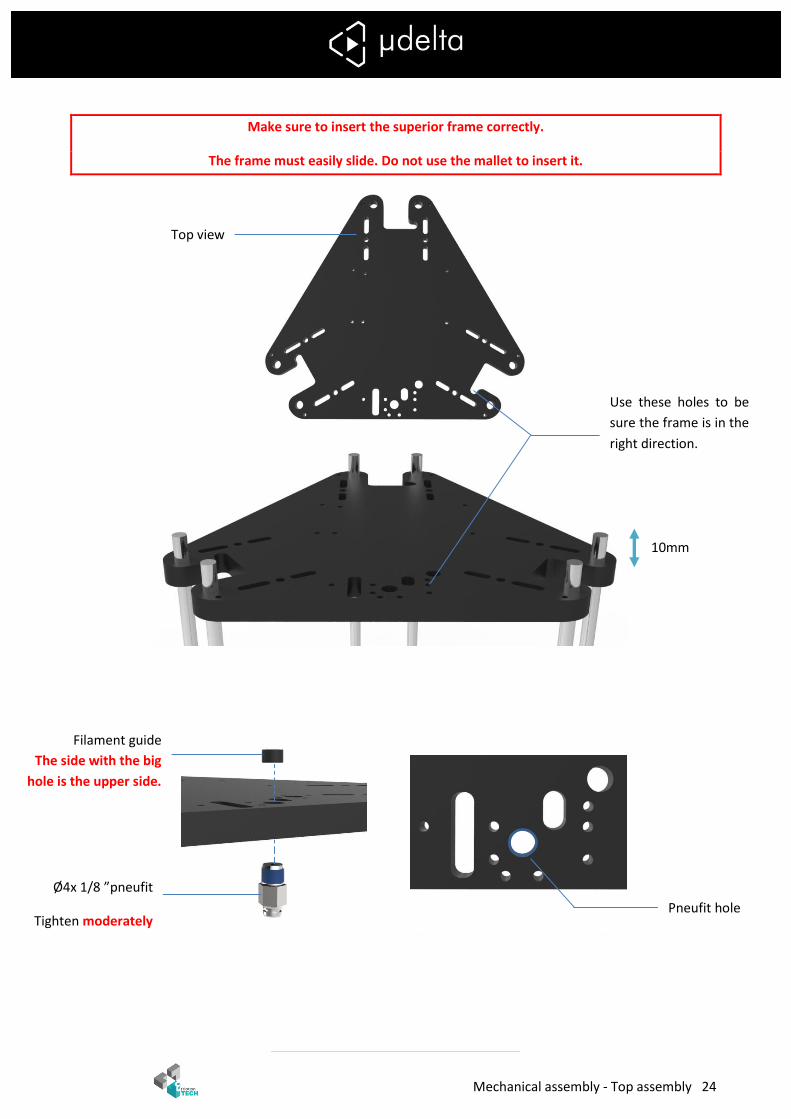
Mechanical assembly - Top assembly 24
Make sure to insert the superior frame correctly.
The frame must easily slide. Do not use the mallet to insert it.
Use these holes to be
sure the frame is in the
right direction.
Top view
Pneufit hole
Filament guide
The side with the big
hole is the upper side.
Ø4x 1/8 ”pneufit
Tighten moderately
10mm

Mechanical assembly - Top assembly 25
Use the long wired endstops for these motors holders
Be careful, the following step is very important!
You have to compare the wire length of the three endstops :
If the 3 wires have the same length, this information may not apply to you. Go to the next page.
If you have 2 wires longer, you have to use this endstop for the motor holder shown below.
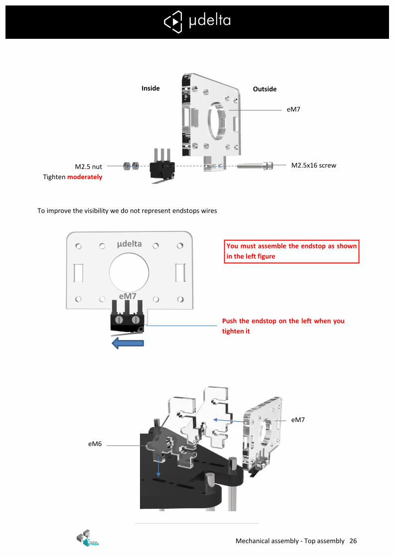
Mechanical assembly - Top assembly 26
To improve the visibility we do not represent endstops wires
You must assemble the endstop as shown
in the left figure
Outside Inside
µdelta
eM7
eM7
eM6
M2.5 nut
Tighten moderately
eM7
M2.5x16 screw
Push the endstop on the left when you
tighten it
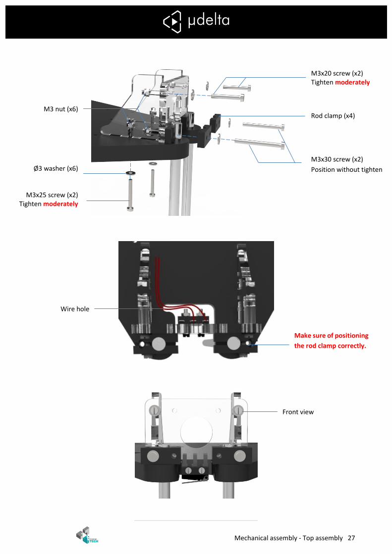
Mechanical assembly - Top assembly 27
M3x20 screw (x2) Tighten moderately
Rod clamp (x4)
M3x30 screw (x2)
Position without tighten
M3 nut (x6)
Ø3 washer (x6)
M3x25 screw (x2) Tighten moderately
Make sure of positioning
the rod clamp correctly.
Wire hole
Front view
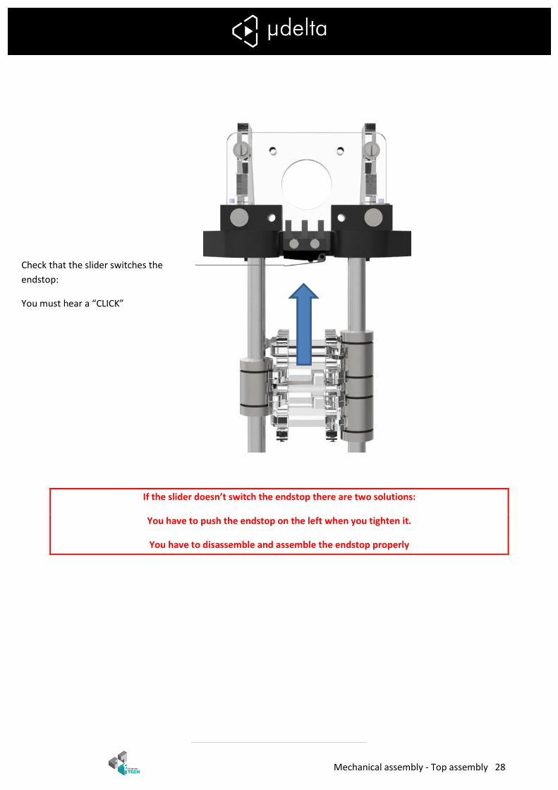
Mechanical assembly - Top assembly 28
If the slider doesn’t switch the endstop there are two solutions:
You have to push the endstop on the left when you tighten it.
You have to disassemble and assemble the endstop properly
Check that the slider switches the
endstop:
You must hear a “CLICK”
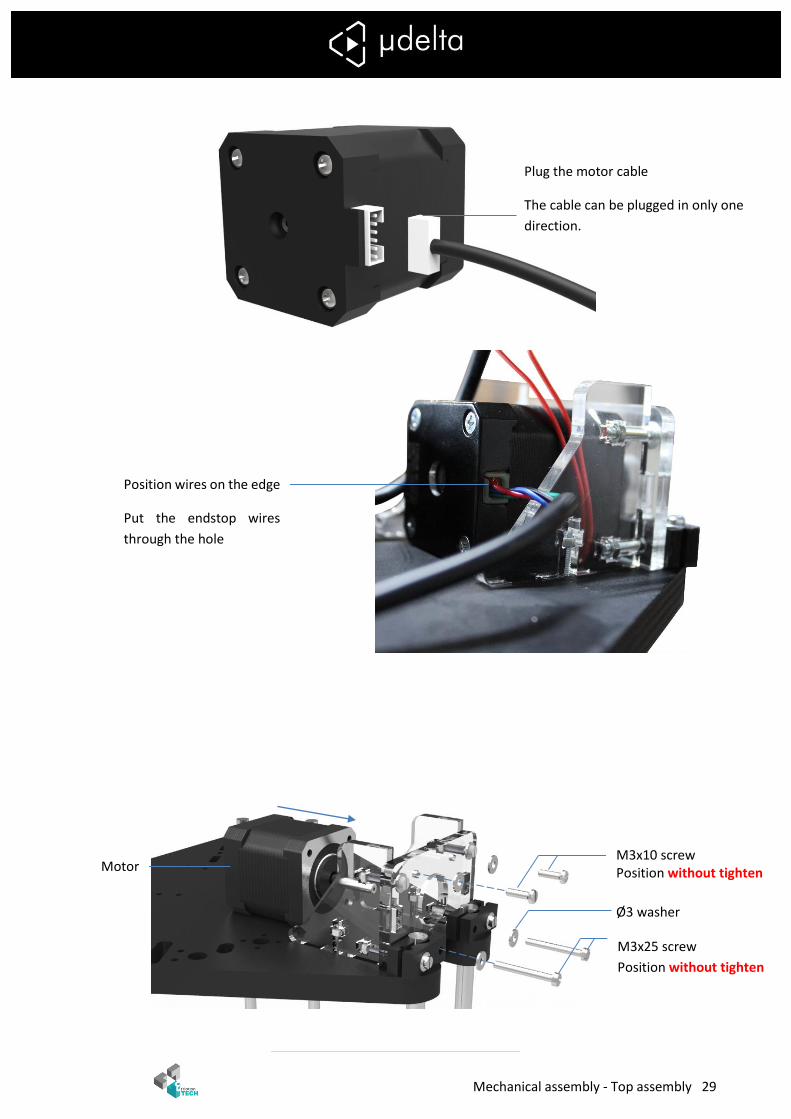
Mechanical assembly - Top assembly 29
M3x10 screw Position without tighten
Ø3 washer
Motor
M3x25 screw
Position without tighten
Position wires on the edge
Put the endstop wires
through the hole
Plug the motor cable
The cable can be plugged in only one
direction.
Mechanical assembly - Top assembly 30
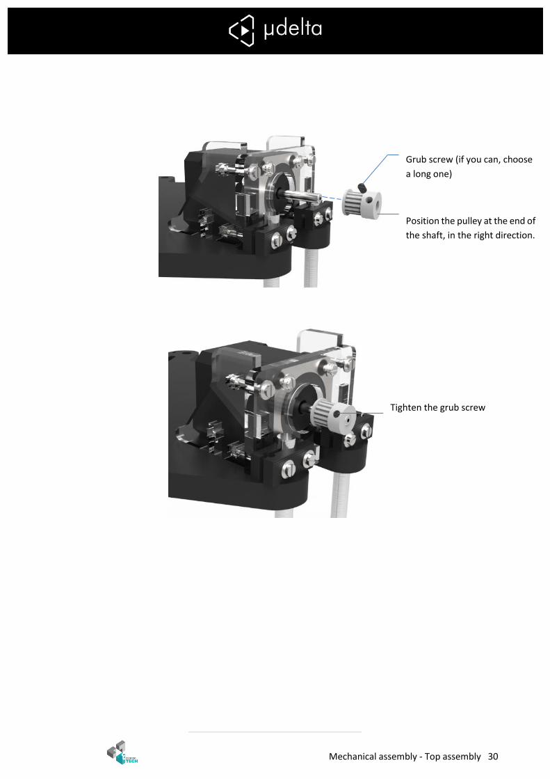
Grub screw (if you can, choose
a long one)
Position the pulley at the end of
the shaft, in the right direction.
Tighten the grub screw
Mechanical assembly - Top assembly 31
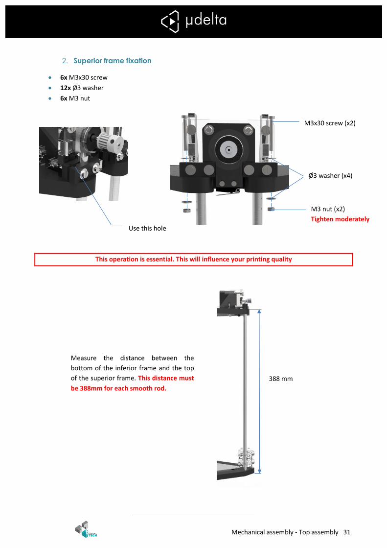
2. Superior frame fixation
6x M3x30 screw
12x Ø3 washer
6x M3 nut
This operation is essential. This will influence your printing quality
Measure the distance between the
bottom of the inferior frame and the top
of the superior frame. This distance must
be 388mm for each smooth rod.
388 mm
M3 nut (x2)
Tighten moderately
Ø3 washer (x4)
M3x30 screw (x2)
Use this hole
Mechanical assembly - Top assembly 32
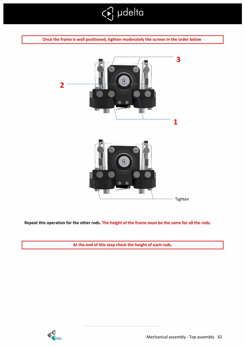
Once the frame is well positioned, tighten moderately the screws in the order below
Repeat this operation for the other rods. The height of the frame must be the same for all the rods.
At the end of this step check the height of each rods.
3
2
1
Tighten
Mechanical assembly - Top assembly 33
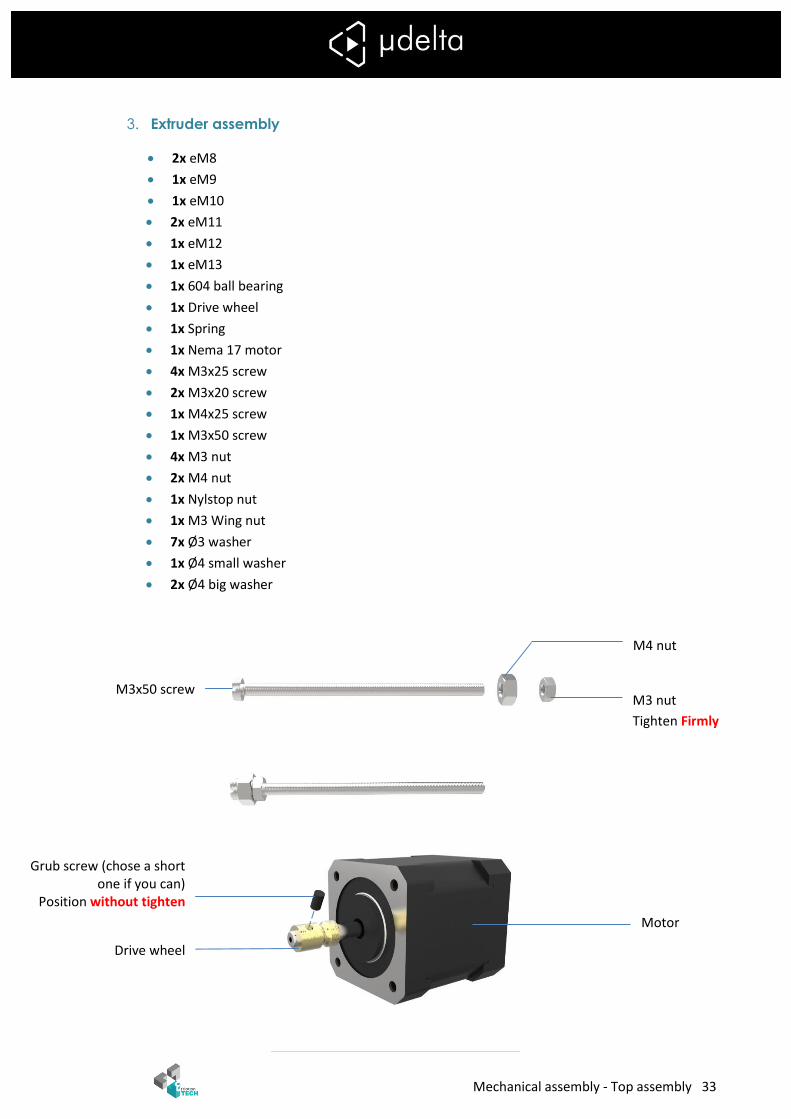
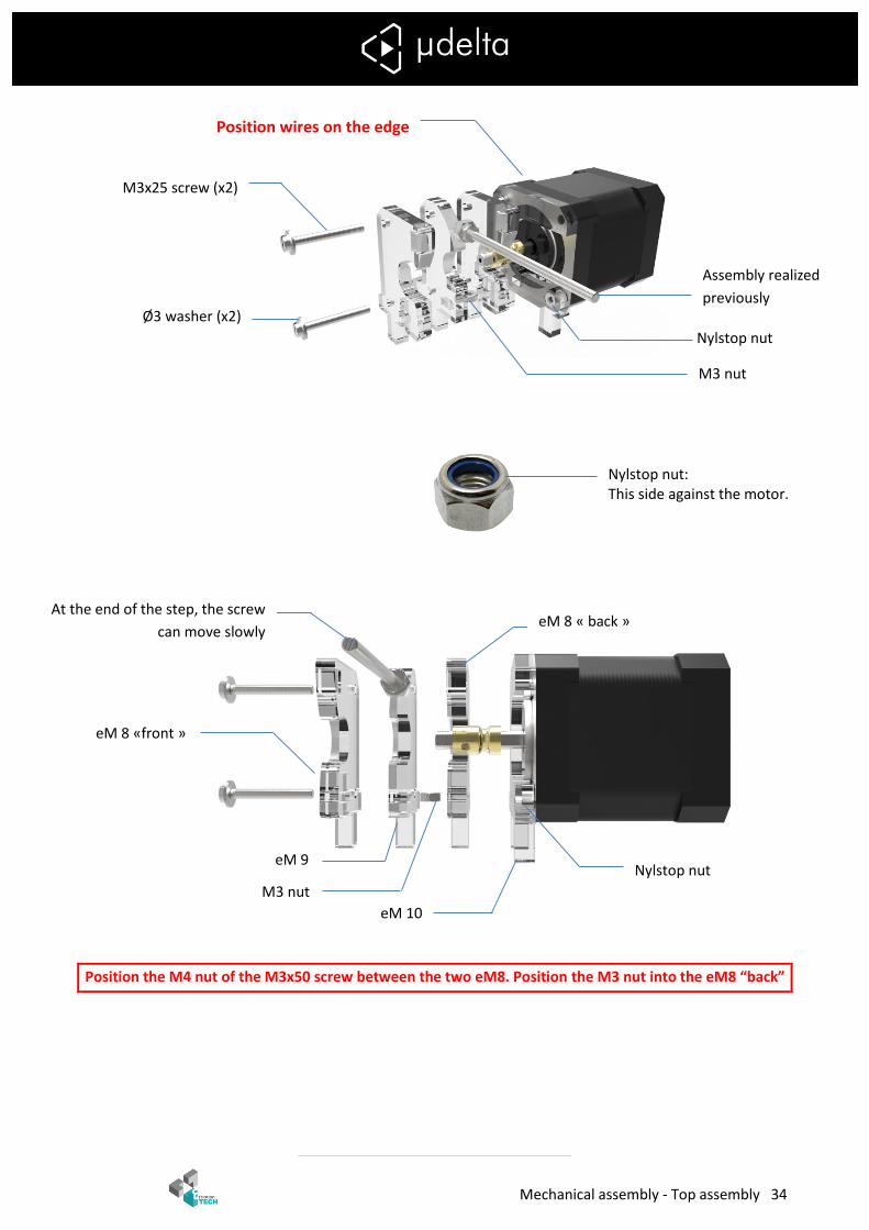
3. Extruder assembly
2x eM8
1x eM9
1x eM10
2x eM11
1x eM12
1x eM13
1x 604 ball bearing
1x Drive wheel
1x Spring
1x Nema 17 motor
4x M3x25 screw
2x M3x20 screw
1x M4x25 screw
1x M3x50 screw
4x M3 nut
2x M4 nut
1x Nylstop nut
1x M3 Wing nut
7x Ø3 washer
1x Ø4 small washer
2x Ø4 big washer
M4 nut
M3 nut
Tighten Firmly
M3x50 screw
Grub screw (chose a short one if you can)
Position without tighten
Drive wheel
Motor
Mechanical assembly - Top assembly 34
Position the M4 nut of the M3x50 screw between the two eM8. Position the M3 nut into the eM8 “back”
M3x25 screw (x2)
Ø3 washer (x2)
Nylstop nut
M3 nut
eM 8 « back »
eM 9
eM 10
eM 8 «front »
Nylstop nut
M3 nut
Nylstop nut: This side against the motor.
Assembly realized
previously
Position wires on the edge
At the end of the step, the screw
can move slowly

Mechanical assembly - Top assembly 35
M4x25 screw
Ø4 small washer
M4 nut Tighten moderately 604 ball bearing
Ø3 washer
Wing nut M3
on the end of the
screw
Spring
Ø4 big washer (x2)
M3x25 screw
Tighten
Position the hollow of the
drive wheel in front of the
eM9
Tighten the M3 grub
screw
eM 11
eM 13
eM 12
eM 11
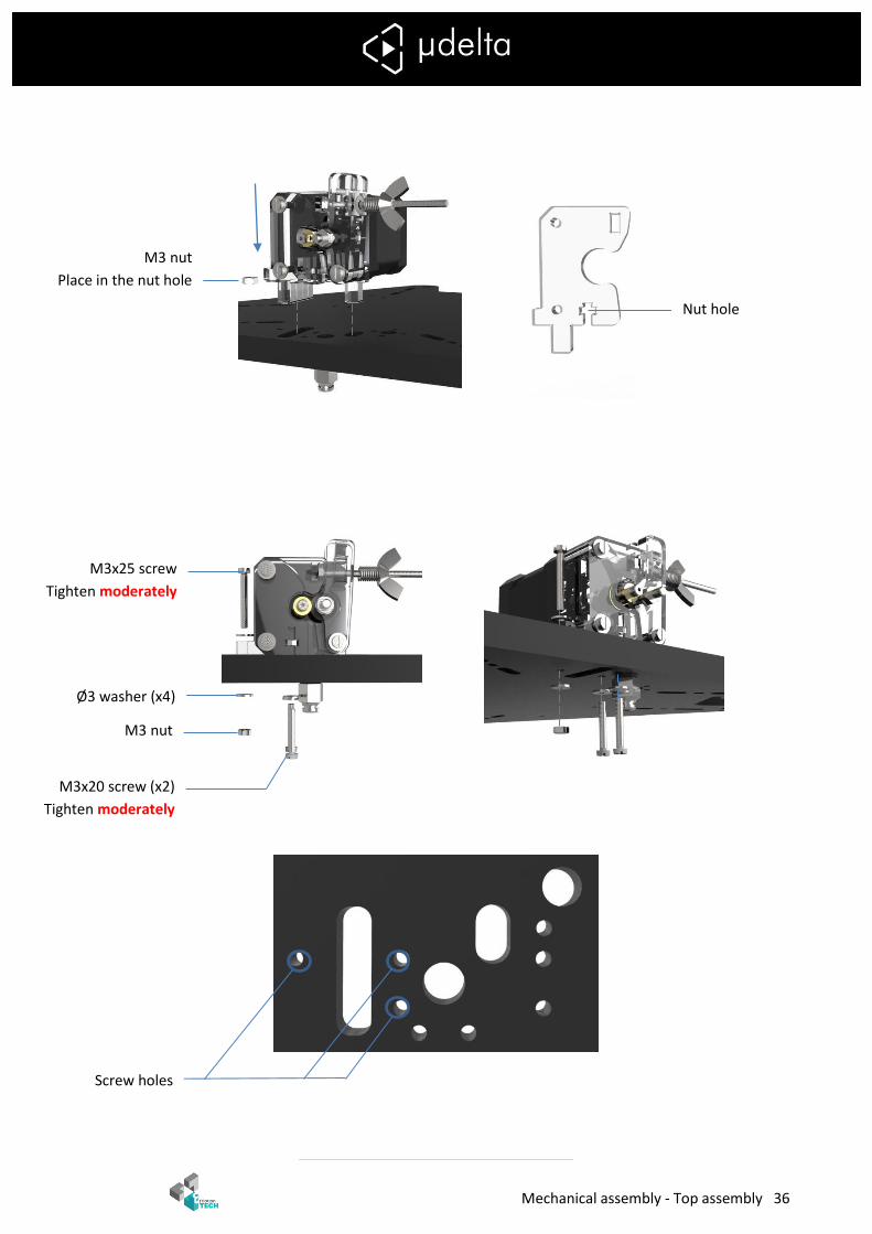
Mechanical assembly - Top assembly 36
M3x25 screw
Tighten moderately
Ø3 washer (x4)
M3x20 screw (x2)
Tighten moderately
M3 nut
M3 nut
Place in the nut hole
Nut hole
Screw holes
Mechanical assembly - Belt positioning. 37
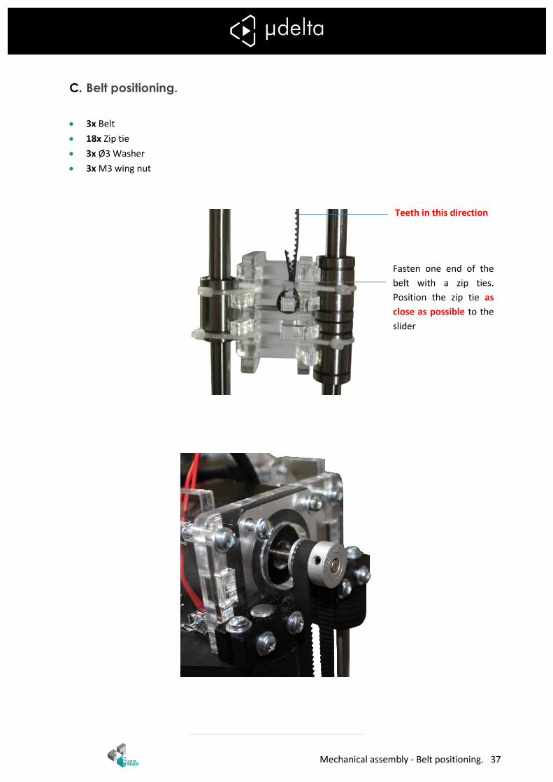
C. Belt positioning.
3x Belt
18x Zip tie
3x Ø3 Washer
3x M3 wing nut
Fasten one end of the
belt with a zip ties.
Position the zip tie as
close as possible to the
slider
Teeth in this direction

Mechanical assembly - Belt positioning. 38
Wing nut at the end of the screw
Ø3 washer
Once the wing nut is positioned,
push the tensioner through the
nut
- Belt positioning. 39
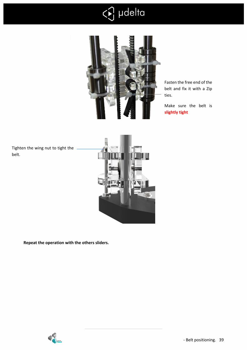
Repeat the operation with the others sliders.
Fasten the free end of the
belt and fix it with a Zip
ties.
Make sure the belt is
slightly tight
Tighten the wing nut to tight the
belt.

Core - Core assembly 40
Core
A. Core assembly
1x core
1x Hexagon 1.75 kit
2x 3x3 Fan
6x M3x20 screw
4x Ø3 washer
1x Ø4xM6mm pneufit
3x Zip tie
Untighten the central pipe
(key provided)
Use a screwdriver to
make it easier

Core - Core assembly 41
Tighten the central pipe
Tighten the nozzle
Use a screwdriver to
make it easier
(Not provided)
It must not have space
between the head and
the nozzle
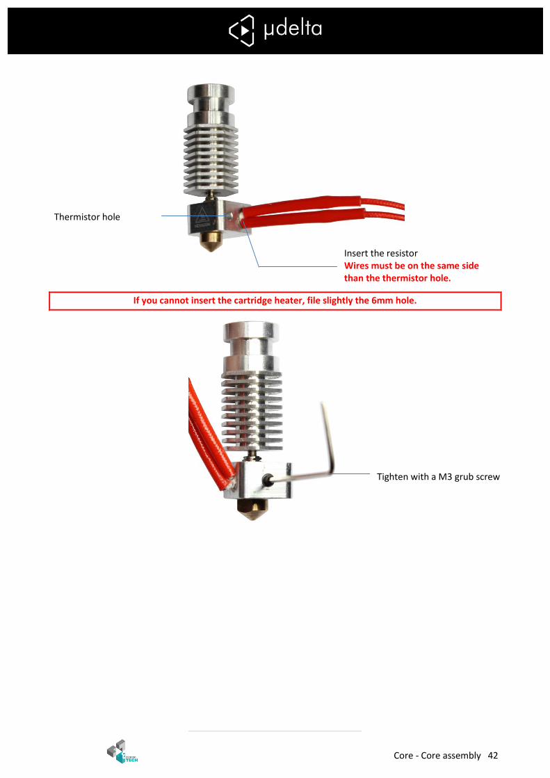
Core - Core assembly 42
If you cannot insert the cartridge heater, file slightly the 6mm hole.
Insert the resistor Wires must be on the same side than the thermistor hole.
Thermistor hole
Tighten with a M3 grub screw
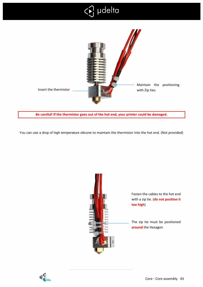
Core - Core assembly 43
Be careful! If the thermistor goes out of the hot end, your printer could be damaged.
You can use a drop of high temperature silicone to maintain the thermistor into the hot end. (Not provided)
Insert the thermistor Maintain the positioning
with Zip ties.
Fasten the cables to the hot end
with a zip tie. (do not position it
too high)
The zip tie must be positioned
around the Hexagon

Core - Core assembly 44
Unscrew the filament guide
Screw the Ø4xM6mm pneufit

Core - Core assembly 45
Put the cables through the wire hole.
If you have LED put the cables through the hole
Zip tie hole
Make sure the core is free of
impurities.
Wire hole
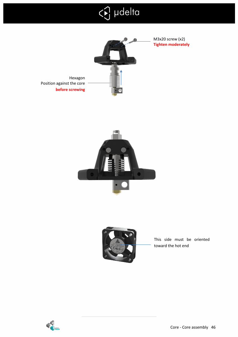
Core - Core assembly 46
Hexagon Position against the core
before screwing
M3x20 screw (x2) Tighten moderately
This side must be oriented
toward the hot end

Core - Core assembly 47
Place the wires of the fan on the same side than the resistor wires
Fan (x2)
Ø3 washer (x4)
M3x20 screw (x4) Tighten Moderately

Core - LED (optional) 48
B. LED (optional)
Parts of the following section are not included in the basic µDelta kit. You can find
them on eMotion Tech website.
1x LED
2x Zip ties
Zip tie hole
Position LED using an
alternating tightening to
center it. Zip tie hole
Zip tie
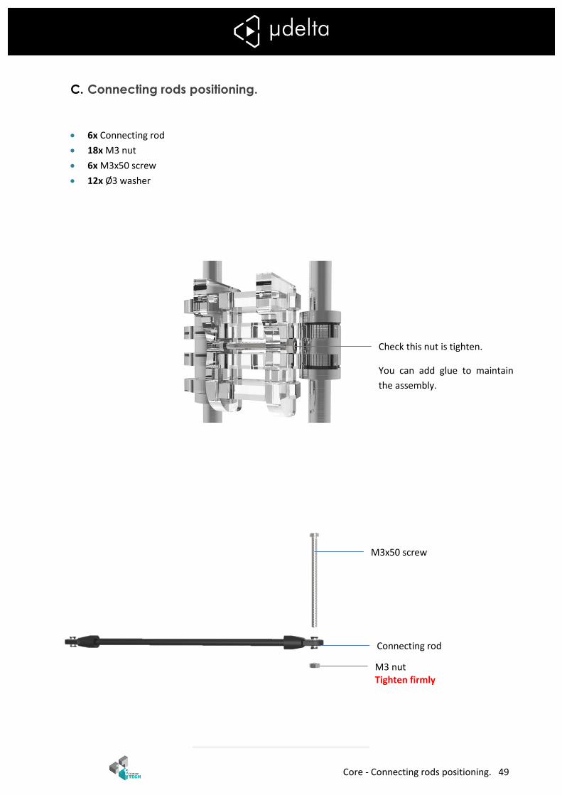
Core - Connecting rods positioning. 49
C. Connecting rods positioning.
6x Connecting rod
18x M3 nut
6x M3x50 screw
12x Ø3 washer
M3x50 screw
screw
Connecting rod
M3 nut Tighten firmly
Check this nut is tighten.
You can add glue to maintain
the assembly.
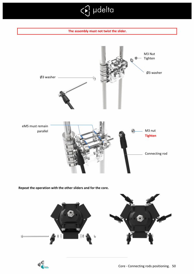
Core - Connecting rods positioning. 50
The assembly must not twist the slider.
Repeat the operation with the other sliders and for the core.
M3 Nut Tighten
Ø3 washer Ø3 washer
M3 nut
Tighten
Connecting rod
eM5 must remain
parallel

Finishing - Connecting rods positioning. 51
Finishing
1x PTFE tube
8x Zip tie
1x braided sleeve
3x pad
1x adhesive tape
1x M3x50 screw
1x M3 nut
1x Ø3 washer
PTFE tube length must be 35cm. cut carefully the end of the PTFE tube if they are flattened
Push the PTFE tube
into the pneufit
Push the PTFE tube
into the pneufit
Push the cables and the PTFE tube
trough the braided sleeve
Fasten the cables with zip ties
PTFE tube
Fold the braided sleeve to
improve the appearance
Finishing - Connecting rods positioning. 52
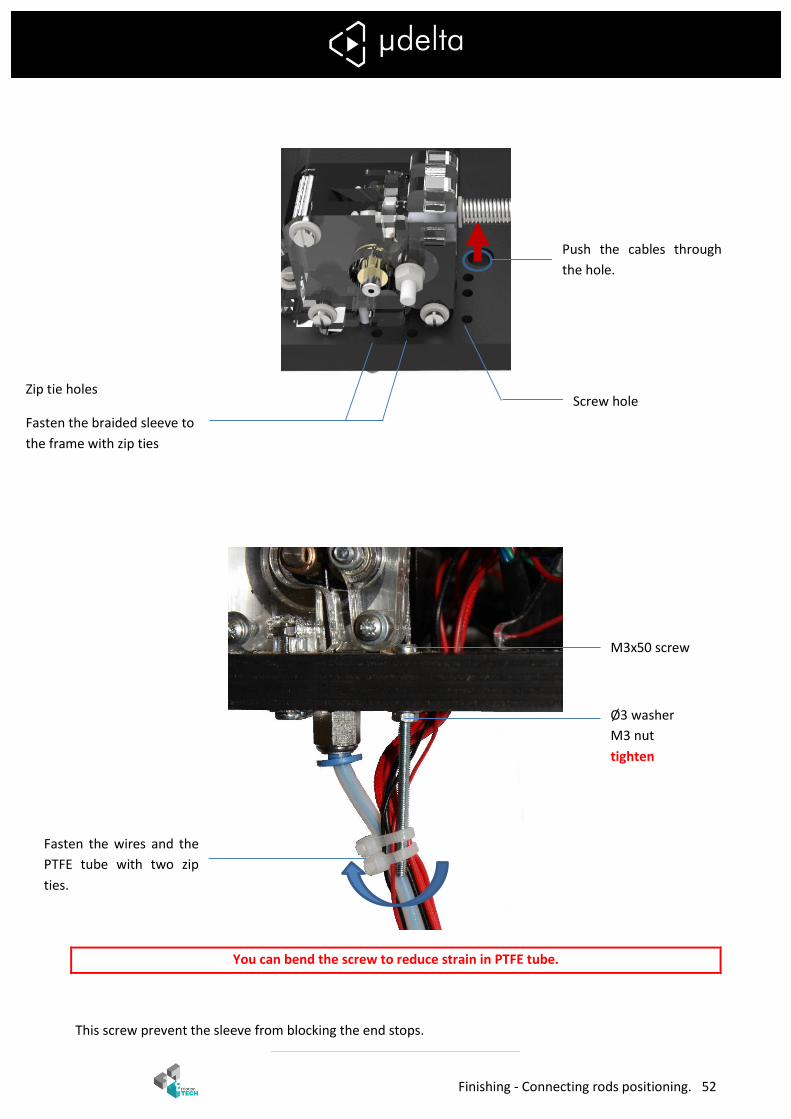
You can bend the screw to reduce strain in PTFE tube.
This screw prevent the sleeve from blocking the end stops.
Push the cables through
the hole.
Zip tie holes
Fasten the braided sleeve to
the frame with zip ties
Screw hole
M3x50 screw
Ø3 washer
M3 nut
tighten
Fasten the wires and the
PTFE tube with two zip
ties.
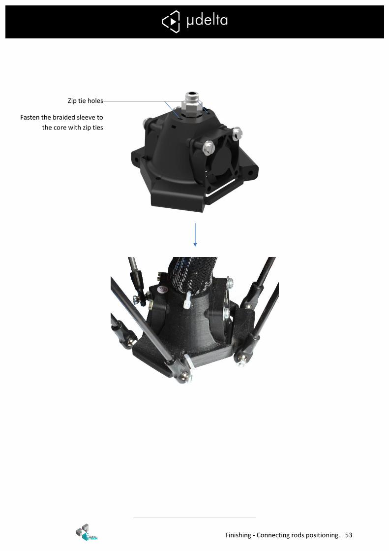
Finishing - Connecting rods positioning. 53
Zip tie holes
Fasten the braided sleeve to
the core with zip ties
Finishing - Connecting rods positioning. 54
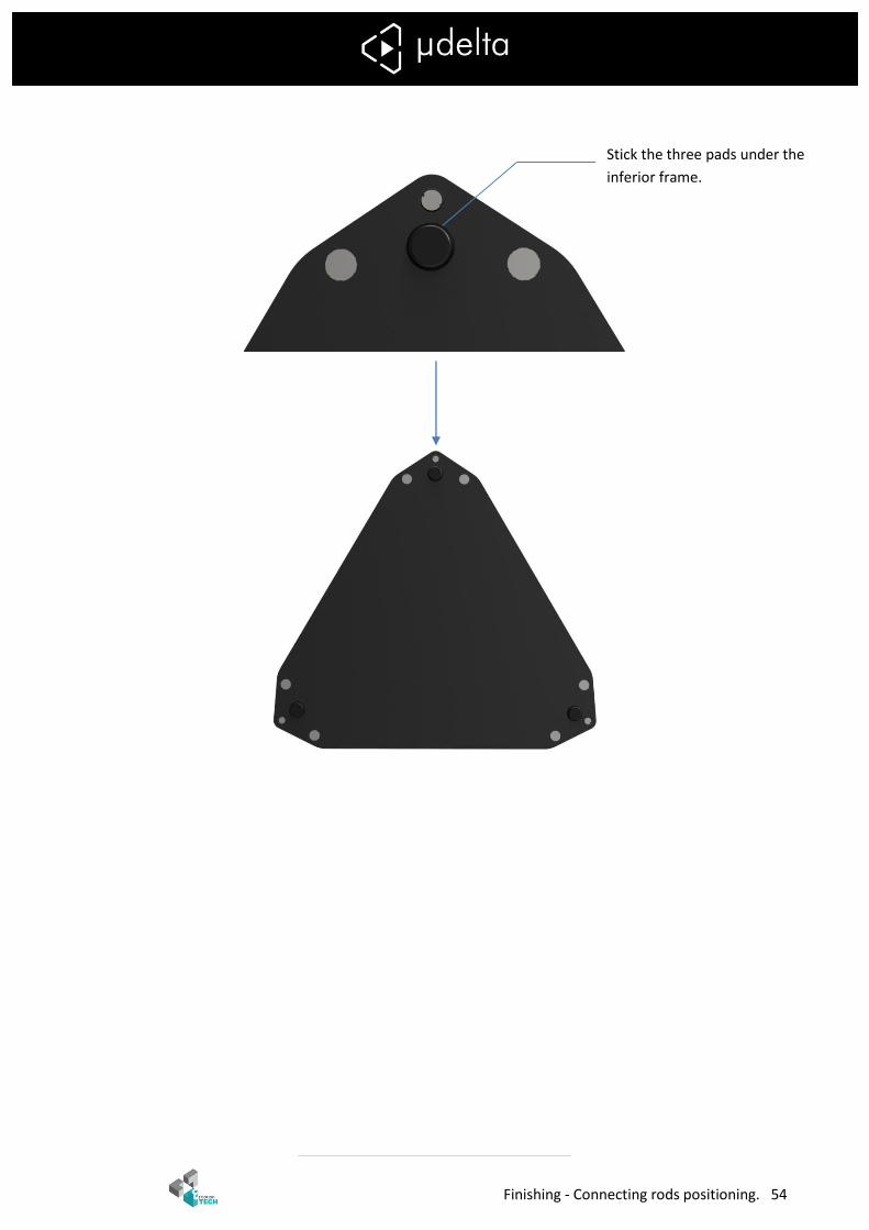
Stick the three pads under the
inferior frame.
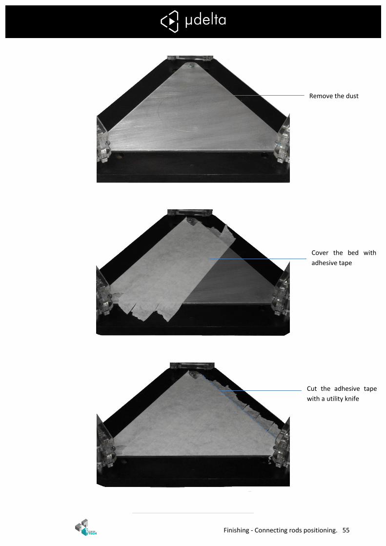
Finishing - Connecting rods positioning. 55
Cover the bed with
adhesive tape
Cut the adhesive tape
with a utility knife
Remove the dust
Electronics assembly - Teensylu 56
Electronics assembly
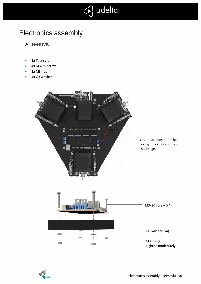
A. Teensylu
1x Teensylu
4x M3x25 screw
8x M3 nut
4x Ø3 washer
You must position the teensylu as shown on this image.
M3x20 screw (x4)
M3 nut (x8) Tighten moderately
Ø3 washer (x4)
X
Electronics assembly - Connections 57
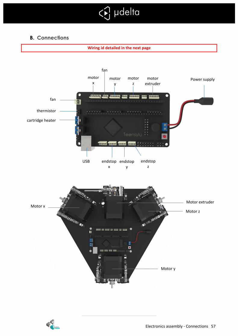
B. Connections
Wiring id detailed in the next page
fan
thermistor
cartridge heater
USB endstop x
X
endstop y
X
endstop z
X
motor x
X
motor y
X
motor z
X
motor extruder
X
fan
Power supply
X
Motor z
Motor y
Motor x Motor extruder
Electronics assembly - Connections 58
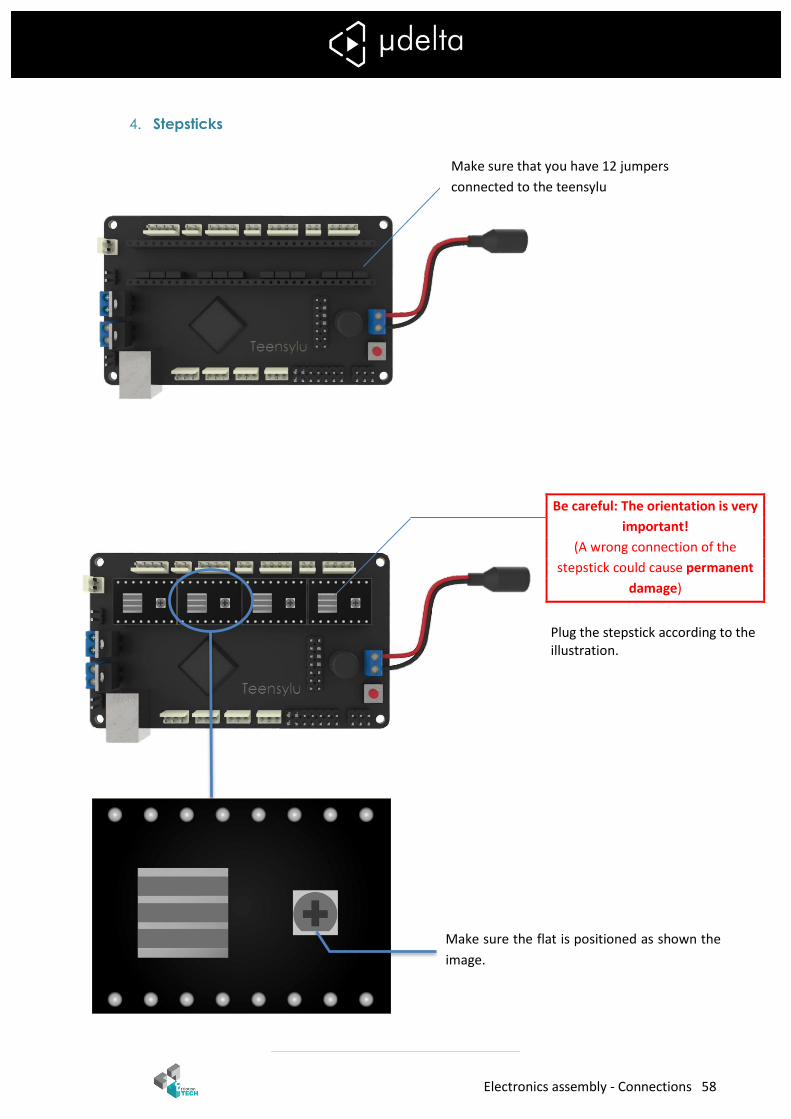
4. Stepsticks
Be careful: The orientation is very
important!
(A wrong connection of the
stepstick could cause permanent
damage)
Plug the stepstick according to the illustration.
Make sure that you have 12 jumpers
connected to the teensylu
Make sure the flat is positioned as shown the
image.
Electronics assembly - Connections 59
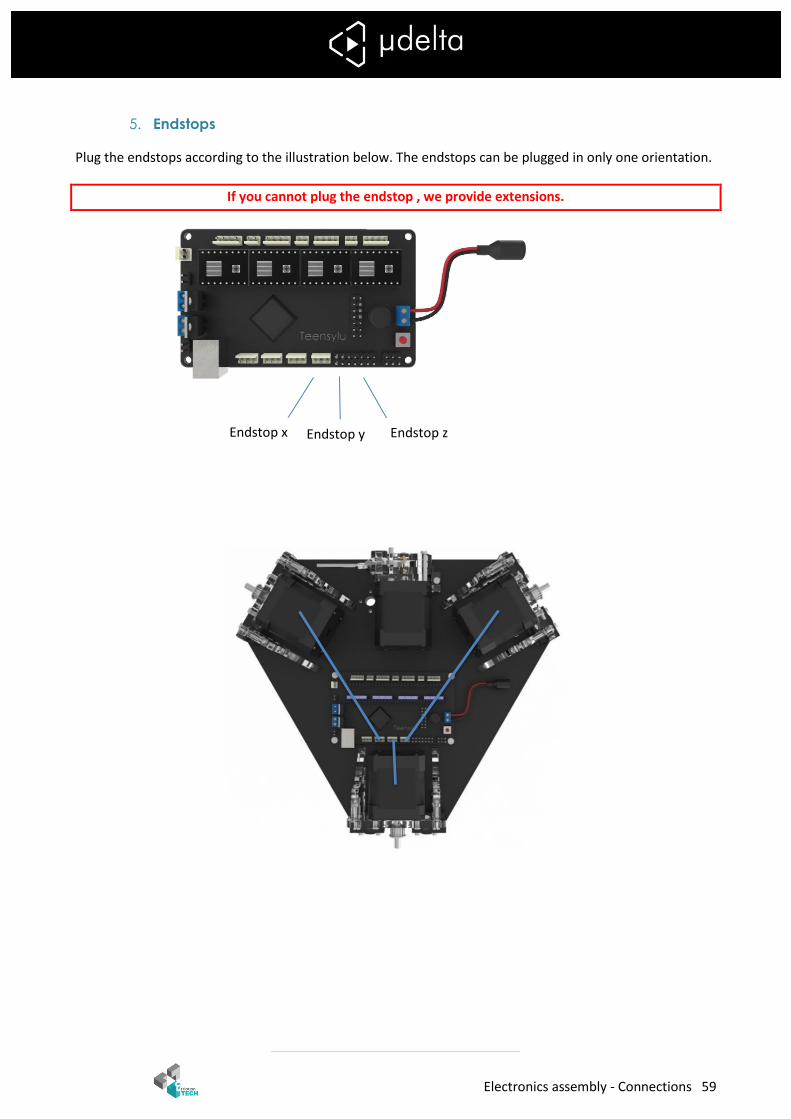
5. Endstops
Plug the endstops according to the illustration below. The endstops can be plugged in only one orientation.
If you cannot plug the endstop , we provide extensions.
Endstop z Endstop x Endstop y
Electronics assembly - Connections 60
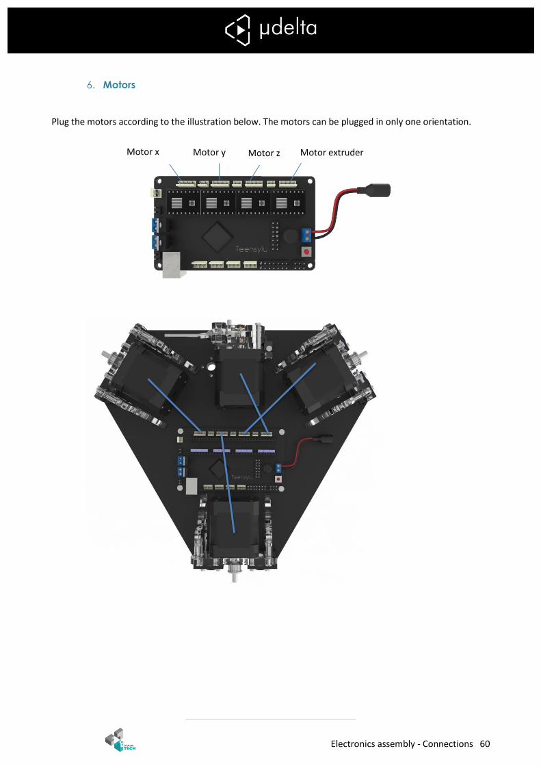
6. Motors
Plug the motors according to the illustration below. The motors can be plugged in only one orientation.
Motor z Motor x Motor y
Motor extruder

Electronics assembly - Connections 61
7. Cartridge heater.
Screw the cable of the cartridge heater.
8. Thermistor
Plug the thermistor.
9. Fans
Plug the fans according to the illustration below. The fans can be plugged in only one orientation.
Electronics assembly - Connections 62
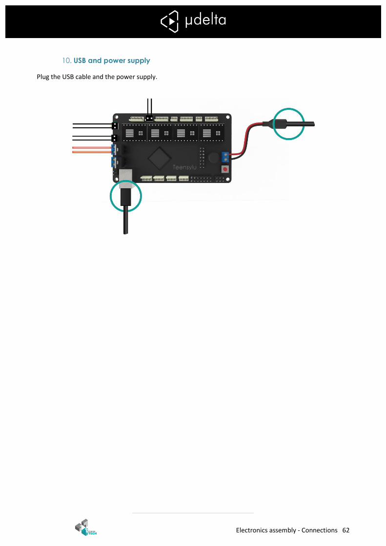
10. USB and power supply
Plug the USB cable and the power supply.
Annex 1: Spool holder - Assembly 63
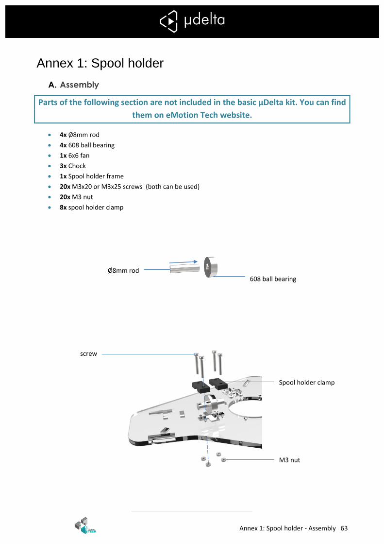
Annex 1: Spool holder
A. Assembly
Parts of the following section are not included in the basic µDelta kit. You can find
them on eMotion Tech website.
4x Ø8mm rod
4x 608 ball bearing
1x 6x6 fan
3x Chock
1x Spool holder frame
20x M3x20 or M3x25 screws (both can be used)
20x M3 nut
8x spool holder clamp
608 ball bearing Ø8mm rod
Spool holder clamp
M3 nut
screw
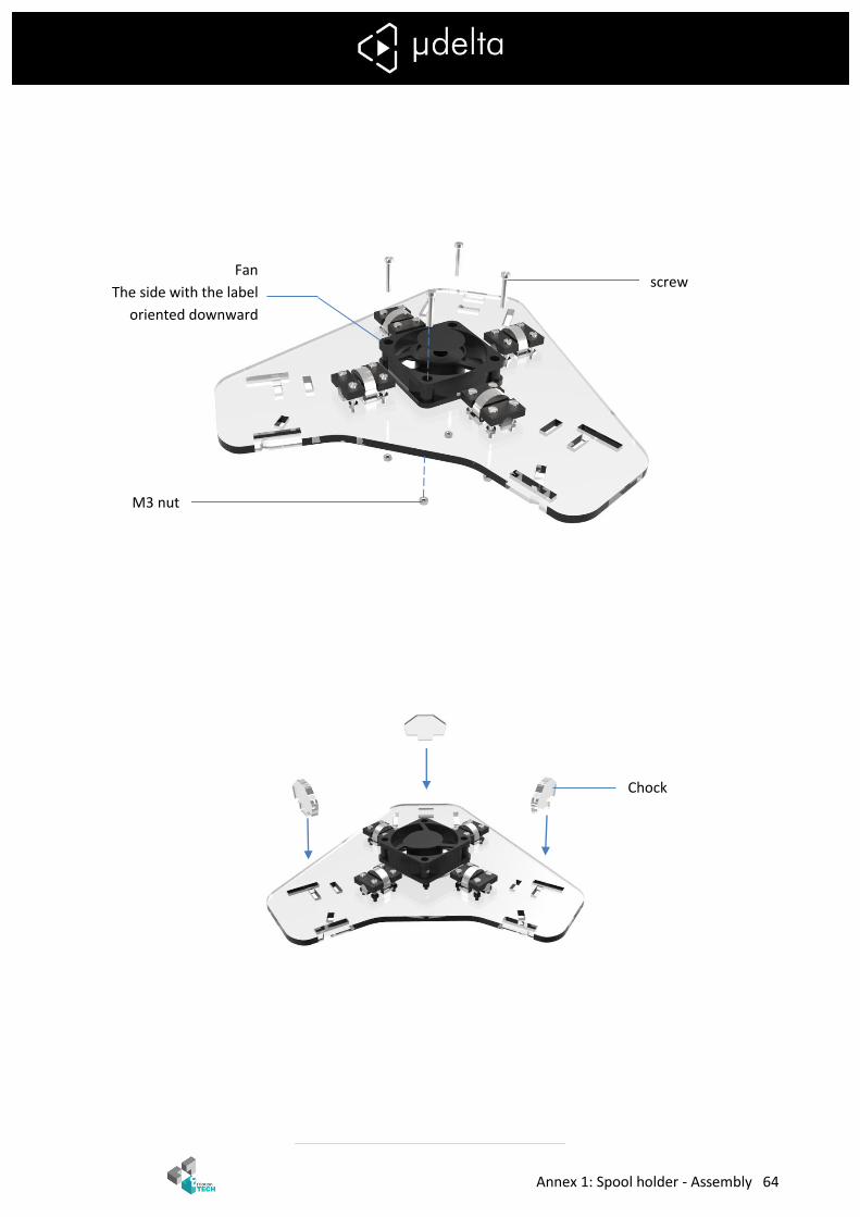
Annex 1: Spool holder - Assembly 64
screw
M3 nut
Chock
Fan
The side with the label
oriented downward

Annex 1: Spool holder - Connections 65
B. Connections
Plug the fan and the LED according to the illustration below. They motors can be plugged in only one orientation.
Spool holder fan LED

Annex 1: Spool holder - 66