versatile experiment spherical torus (vest) toward advanced …psl.postech.ac.kr/kjws19/talks/jk hcd...
TRANSCRIPT

Experimental results and plans of VEST
Y.S. Hwang and VEST team
March 19, 2019
CARFRE and CATS
Dept. of Nuclear EngineeringSeoul National University
Versatile Experiment Spherical Torus (VEST)
toward Advanced Tokamak Study
Korea-Japan Workshop on Physics and Technology of Heating and Current Drive
Seoul National University, Seoul, Korea, March 19-20, 2019

1/25
Present Upgrade
Toroidal B Field 0.1 T 0.2T
Major Radius 0.44 m 0.4 m
Minor Radius 0.32 m 0.3 m
Aspect Ratio >1.37 >1.33
Plasma Current <120 kA <300 kA
H & CD
(ECH, NBI, LHFW)
ECH (2.45GHz, 30kW)
NBI (15keV, 600kW)
LHFW (500MHz, 10kW)
ECH (7.9GHz, 3kW)
NBI ( 20keV, 1.2MW)
LHFW (500MHz,200kW)
Specifications
VEST (Versatile Experiment Spherical Torus)
The first and only Spherical Torus (ST) device in Korea
Basic research on a compact, high- ST
Study on innovative start-up, non-inductive H&CD, high ,
disruption, innovative divertor concept, energetic particle, etc

2/25
Introduction : Versatile Experiment Spherical Torus (VEST)
Device and machine status
Start-up experiments
Robust start-up method with trapped particle configuration
Closed flux surface formation as a successful start-up criterion
Solenoid-free start-up from outboard with outside PF coils
Studies for Advanced Tokamak
Research directions for high-beta and high-bootstrap STs
Preparation for heating and current drive systems / diagnostic systems
MHD studies
Summary
Outline

3/25
VEST device and Machine status
VEST device and
Machine status

4/25
VEST device and Machine status
History of VEST Discharges
• #2946: First plasma (Jan. 2013)
• #10508: H2 GDC (Nov. 2014)
• #14945: He GDC, Boronization (Mar. 2016)
• #19351: Slower ramp-up and diverted plasma (May. 2018)
#2946 #10508
#14945
#19351
Time (ms)
Pla
sm
a c
urr
en
t (k
A)
R/a = 1.3
High beta and bootstrap current
Low aspect ratio and high Ip/ITF

5/25
Start-up Experiments
Start-up Experiments

6/25
Start-up experiments
Trapped Particle Configuration (TPC)
• Efficient and robust tokamak start-up demonstrated with wider operation window at VEST and KSTAR
Pressure, ECH power and low loop voltage
• TPC: Mirror like magnetic field configuration– Enhanced particle confinement– Inherently stable decay index structure for Bv
Y. An et al., Nucl. Fusion 57 016001 (2017)
0.1 0.2 0.3 0.4 0.5 0.6 0.7 0.8-1.0
-0.5
0.0
0.5
1.0
1.5
2.0
Decay In
dex
Major Radius [m]
Trapped Particle
Conventional w/ stable Bv
Conventional
J.W. Lee et al., Nucl. Fusion 57, 126033 (2017)

7/25
400 401 402 403 404 405 406 407 408 409 410
0
1000
2000
3000
4000
5000
6000 B
0~500 G / ECH 6 kW
B0~500 G / ECH 4 kW
B0~500 G / ECH 2 kW
Time (ms)P
las
ma
Cu
rre
nt
(A)
-3.0x10⁻³
-2.0x10⁻³
-1.0x10⁻³
0.0
1.0x10⁻³
2.0x10⁻³
3.0x10⁻³
Ve
rtica
l Fie
ld (T
)
Start-up Experiment
Closed Flux Surface Formation for Successful Start-up in TPC
Criterion for successful start-up can
be set with closed flux formation, i.e.
poloidal field from plasma current
exceeds vacuum vertical field.
H.Y. Lee
𝐴 = 𝜋𝑟2𝐴 = 𝜋𝑟2
Bv (G) < Bp = 2*Ip(kA)/a(m)
Loop voltage,
Pressure and ECH power
There is another limit ofvertical field strength
for successful start-up !

8/25
Start-up Experiment
Solenoid-free Start-up from Outboard with Outer Poloidal Field Coils
Solenoid-free Startup using outer PF coils assisted by enhanced 2.45 GHz EBW pre-ionization
Startup criteria for Closed Flux Surface (CFS) formation
Successful outer PF Startup region of CFS location & size
Lowering plasma resistivity by optimizing EBW pre-ionization
𝑳 = µ𝒐𝑹𝒐 (ln𝟖𝑹𝒐
𝒂+𝒍𝒊
𝟐- 2)
𝒅𝑹𝒐
𝒅𝒕< 0
𝒅𝑳
𝒅𝒕< 0
𝑳𝒅𝑰𝒑
𝒅𝒕= 𝑽𝒍 - 𝑰𝒑 (
𝒅𝑳
𝒅𝒕+ 𝑹𝒑 ) > 0
R=0.60m
a=0.15m
R=0.40m
a=0.30m
To reach target resistivity, higher ECH power of ~45kW may be needed
to have sufficient density and temperature in the pre-ionization phase.
Required ECH power will be reduced by optimizing EBW pre-ionization

9/40
Start-up experiments in VEST
EBW Pre-ionization via Collisional Heating with Different Resonance Fields
In case of Bo ~ 500 G
• The density peak exists near ECR with low ECH
• Steep density gradient is produced near UHR : improvement on XB MC
• Over dense plasma : EBW collisional damping
In case of Bo ~ 1000 G
• Over dense plasma between ECR and UHR

10/25
Preparation for Advanced Tokamak Studies
Studies for Advanced Tokamak

11/25
Preparation for Advanced Tokamak Studies
Scopes of Advanced Tokamak Studies in VEST
Fusion reactor requires
high beta (or Q) and high bootstrap current
Simultaneously
Alpha heating dominant (high Q)
Centrally peaked pressure profile
Confinement and Stability?
High power neutral beam heating
High Bootstrap current fraction (high fb)
Hollow current density profile (low li)
Current density profile control
Bootstrap/EBW/LHFW
Profile diagnostics

12/25
Preparation for Advanced Tokamak Studies
Simulations for the VEST Advanced Tokamak Scenario C.Y. Lee/Y.S. Na
• The integrated modeling system constructed.
- ASTRA+TGLF and NEO for heat & particle transport: Valid even in low aspect ratio tokamak
• The steady state solution of beam discharges showing that 𝑇𝑒0~0.8 𝑘𝑒𝑉, 𝑇𝑖0~0.5 𝑘𝑒𝑉 can be achieved by considering beam heating & fueling simultaneously.
𝛽𝑁~7, 𝑓𝐵𝑆~0.5, 𝑓𝑁𝐼~0.75

13/25
Neutral Beam Injection System
with ~600kW at 15keV
from KAERI
Thomson Scattering
with Nd:YAG laser
from SNU/NFRI/JNU/SogangU
Preparation for Advanced Tokamak Studies
Diagnostics, Heating and Current Drive Systems in VEST
Low Hybrid Fast Wave H/CD
with ~10kW at 500MHz
from KAERI/KAPRA/KWU
ECH
Electron Cyclotron/
Bernstein Wave H/CD
with ~30kW at 2.45GHz
from SNU/KAPRA
Interferometry
with 94GHz, multi-channel
from SNU/UNIST
Magnetics and Spectroscopy
Interferometer
Heating and Current Drive Systems Profile Diagnostic Systems

14/25
High power central heating
High Power NBI System : NBI Commissioning on VEST
B.K. Jung/K.H. Lee
Neutral beam injection system (600 kW at 15keV)
1 MW NBI developed by KAERITested up to 200 kW / Target 600 kW (VEST)

15/25
High power central heating
High Power NBI System : NBI Commissioning on VEST
B.K. Jung/K.H. Lee
-2 0 2 4 6 8 10 12-10
0
10
20
-10
0
10
20
30
40
Vo
lta
ge
(k
V)
V_PE
V_SE
Time (ms)
Cu
rre
nt
(A)
I_PE
I_SENeutral Beam Center stack of VEST
Commissioning shots Up to 200kW (10kV 20A 10msec)
-2 0 2 4
0
10
20
30-10
0
10
20
30
40
50
Vo
lta
ge
(k
V)
V_PE_before
V_SE_before
V_PE_after
V_SE_after
Time (msec)
Cu
rre
nt
(A)
I_PE_before
I_SE_before
I_PE_after
I_SE_after
Conditionning effect
< Before NB injection > <NB injection >
16/25
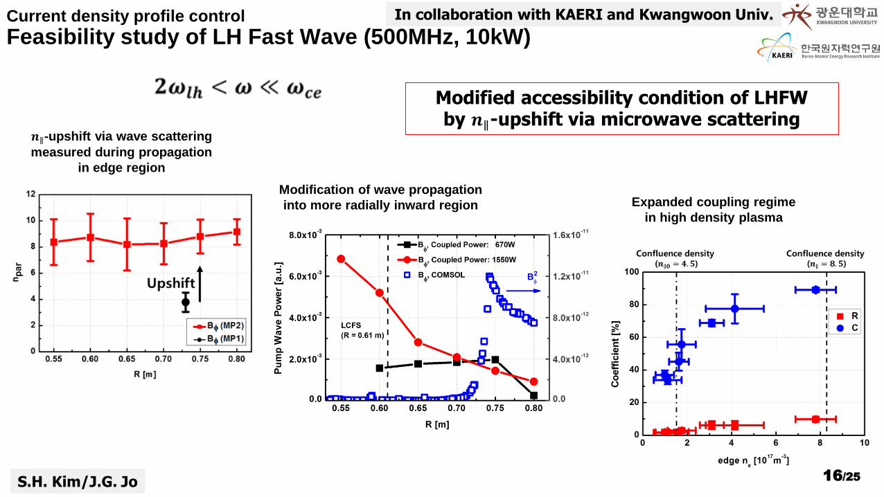
In collaboration with KAERI and Kwangwoon Univ.Current density profile control
Feasibility study of LH Fast Wave (500MHz, 10kW)
S.H. Kim/J.G. Jo
Modified accessibility condition of LHFW by 𝒏∥-upshift via microwave scattering
𝒏∥-upshift via wave scattering
measured during propagation
in edge region
Modification of wave propagation
into more radially inward region Expanded coupling regime
in high density plasma

17/35Status and plan for VEST
EBW heating (6kW cw+10kW pulse at 402ms) on Ohmic plasmas
Current density profile control
EBW Heating with XB Mode Conversion
H.Y. Lee
400 401 402 403 404 405 406 407 408 409 410 411 4120
5
10
15
20
25
30
35
40
45
50
55
60
Pla
sm
a C
urr
en
t (k
A)
Time (ms)
off
on
• Boronization (impurity removal) and higher plasma
current (higher electron temperature)
• No change in the electron density profile with
additional MW – no additional collisional damping
• Electron temperature rises two times near 3rd
harmonics ECR resonance : the first resonance
position after EBW mode conversion

18/25
Preparation for Advanced Tokamak Studies
VEST Diagnostic Systems
Diagnostic Method Purpose Remarks
MagneticDiagnostics
Rogowski CoilPlasma current & eddy
currentin-vessel coils
Pick-up Coil & Flux Loop
Bz, Br &Loop voltage, flux
49 pick-up coils11 loops
Magnetic Probe Array
Bz, Br measurement inside plasma
Movable array
Probes Electrostatic Probe Radial profile of Te, ne
2 Triple ProbesMach probe
OpticalDiagnostics
Fast CCD camera Visible Image 20kHz
Hα monitoring Hα Hα filter+ Photodiode
Impurity monitoring O & C lines Spectrometer
Interferometry Line averaged ne 94GHz, multi-channel
Imaging Fabry-PérotInterferometer
edge Ti
Multi-channel with fiberarray
Charge Exchange Spectroscopy
Rotation and Ti CES/BES with DNB
Thomson Scattering Te, ne profile Nd:YAG laser

19/25
Profile diagnostics
Thomson Scattering System UpgradeIn collaboration with
New fast digitizer (CAEN V1742) 5 GS/s × 32 ch.
Additional polychromator 2 points measurement
Nd:YAG laser system (BeamTech Inc. SGR-20)
Laser energy: 0.85 J 2.0 J
Repetition rate: 10 Hz 1 kHz (10 pulses)
Optical loss: 23% 4%
Recent result of N2 Rayleigh scattering measurement
Y.G. Kim, D.Y. Kim, J.H. Kim

20/25
Profile diagnostics
Visible optical spectroscopy
Measurement quantities : 𝑻𝒊, 𝒗𝑻, 𝒏𝒁 Passive emission spectroscopy
CIII 464.74 nm and OII 464.90 nm Line-integrated spectra spectral inversion
Specification Detection range : 0.39 m< R <0.71 m Spatial resolution : 20-22 mm Temporal resolution : 2 ms for 9ch, 0.2 ms(for 1ch)
CES/BES combined system is in preparation
Y.S. Kim In collaboration with
⋯
Slit
⋯
7 channel
HDG105 mm
f/14
EMCCD
85 mmf/1.4
140 channel
Geometric centerLCFS
#20913 308.1 ms Ch9
Total fit
3-CIII
2-OII

21/25
MHD studies
Ohmic Discharges: Adjust ramp-up rate for MHD suppression
𝜓𝑁
𝒒
#18452, 0.305 s #19160, 0.305 s
• Hollow current density profile
– Fast ramp-up and high prefill gas pressure
• High current without MHD activity
– Slower Τ𝑑𝐼𝑃 𝑑𝑡: Peaked 𝐽𝜙 profile
– Low prefill gas pressure: Low resistivity
𝑱𝝓 (A/cm2)
Time (s)
OI / Hα
Δin
Τ𝒅𝑩𝒁 𝒅𝒕 (T/s)
𝑰𝑷 (MA)
𝒑𝟎 (10-5 Torr)
2/1
#18452 #19160J.H. Yang

22/25
MHD studies
Ohmic Discharges: MHD activity suppressed by prefill gas control
J.H. Yang
𝜓𝑁
𝒒
#18731, 0.306 s #19157, 0.306 s
• MHD depends on current density profile only?
• Higher prefill gas pressure:
– Lower 𝑇𝑒, less hollow 𝐽𝜙 profile but more TM
– Due to more neoclassical drive (higher 𝛽𝑁)
• Neoclassical feature of TM
𝑱𝝓 (A/cm2)
Time (s)
OI / Hα
𝑉𝜙 (V)
Τ𝑑𝐵𝑍 𝑑𝑡 (T/s)
𝐼𝑃 (MA)
𝑝0 (10-5 Torr)
2/1 + 3/2
#18731 #19157

23/25
MHD studies
Lower 𝒍𝒊 startup by tearing mode suppression J.H. Yang
𝒒𝟗𝟓
𝒍 𝒊
■ #19160, 0.308 s■ #18731, 0.306 s
□ Max. Τ𝛿𝐵 𝐵 < 1 %
□ Max. Τ𝛿𝐵 𝐵 > 1 %
(Stable)
(Unstable)Kink/double tearing limit
Startup at 𝒍𝒊 ~ 0.5 without MHD activity available
Suppress TM by e.g. lower 𝜷𝑵
Time (s)
𝛽𝑁
#19160 #18731
𝛿𝐵 (T/s) 𝐼𝑃 (kA)
Black squares:
Stable shots at unstable region

24/25
Summary
Ohmic operation with 𝑰𝑷 < 120 kA, 𝜿 < 2 and 𝒒𝟗𝟓 < 5 achieved
MHD suppression and diverted configuration
Efficient start-up with TPC (Trapped particle configuration) and EBW heating
TPC start-up with low 𝑉𝑙, low ECH power, and wider pressure window
Closed flux surface formation as a successful start-up criterion
Solenoid-free start-up utilizing efficient EBW pre-ionization at outboard under development
Preparation for the study of Advanced Tokamak with strong central heating
High power (>600 kW) NBI system commissioning
EBW/LHFW heating and current drive experiments
Various diagnostics are under preparation
MHD studies are performed

25/25
Thank you for your attention !

Tearing modes during tokamak plasma current ramp upPage 26
Profile diagnostics
External/Internal Magnetic Diagnostics
• Equilibrium reconstruction: EFIT [5] + transient open field current
– Reconstruction of low plasma current < 100 kA
• Mode identification: Fourier analysis + SVD [6]
– Poloidal & toroidal mode numbers
• Internal Magnetic Probes [7]
R (m)
Z (
m)
Poloidal plane view
Flux loops
Inte
gra
ted
Mirn
ov
coils
[5] Lao et al. NF 1985
[6] Kim et al. PPCF 1999
[7] Yang et al. RSI 2014

27/25
Profile diagnostics
Thomson Scattering System
• Measurement target
– ne: > 5×10¹⁸ m-3
– Te: 10-500 eV
– core plasma
• Laser: 0.65 J/pulse, 1064 nm
• Collection solid angle: ~50 msr
• Scattering length: ~5 mm
• Filter polychromator: 4 channels
Spectral Response
of the polychromator
In collaboration with
Schematic of the TS system
Y.G. Kim/D.Y. Kim

28/25
Profile diagnostics
94 GHz Multi-channel Interferometer
• Microwave system with heterodyne interferometer
• 3.2 GHz IF (avoid EC noise)– EC 2.45 GHz
• Single chord multi-chord
In collaboration with
J.I. Wang

29/25
Ramp-up Experiments
MHD mode number and island location from magnetics
R (m)
Tim
e (
s)
Τ𝑑𝐵𝑍 𝑑𝑡(T/s)
Shots #18452 – 18457
𝑅0
q=3q=2 q=2
q=3
Shot #18452
𝐼𝑃 (MA)
𝑚
𝑓 (kHz)
Τ𝑑𝐵𝑍 𝑑𝑡 (T/s)
Τ𝑑𝐵𝑍 𝑑𝑡 (T/s)
𝒏 = -1𝒏 = -2
2/13/1
3/2 4/2
Time (s) Time (s)
𝑞95
𝑞min.
• Island position:
Peak Τ𝑑𝐵𝑍 𝑑𝑡 location
• Agree with flux surface at
m/n = 3/1 and 2/1 (and 4/1)
• Central 𝑞 large uncertainty:
Surface m/n = 3/2
1.5
J.H. Yang

30/25
VEST device and Machine status
120kA Diverted Plasma (#19351) S.C. Kim
Coil Switching
O impurity drop
31/25
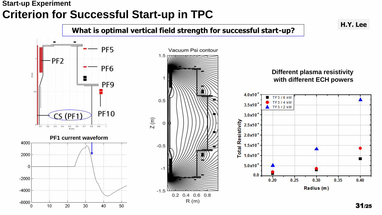
Start-up Experiment
Criterion for Successful Start-up in TPCH.Y. Lee
What is optimal vertical field strength for successful start-up?
PF1 current waveform
Different plasma resistivity
with different ECH powers