veritas storage foundation and ha solutions microsoft ... · pdf fileand high availability...
TRANSCRIPT
September 2012
Veritas Storage Foundation™ and High Availability Solutions Microsoft Clustering Solutions Guide for Microsoft SQL 2005, 2008, 2008 R2, and 2012
Windows Server 2008 (x64), Windows Server 2008 R2 (x64)
6.0.1

Veritas Storage Foundation and HA SolutionsMicrosoft Clustering Solutions Guide for Microsoft SQL 2005, 2008, 2008 R2, and 2012
The software described in this book is furnished under a license agreement and may be used only in accordance with the terms of the agreement.
Product version: 6.0.1
Document version: 6.0.1 Rev 0
Legal Notice
Copyright © 2012 Symantec Corporation. All rights reserved.
Symantec, the Symantec Logo, Veritas, Veritas Storage Foundation, CommandCentral, NetBackup, Enterprise Vault, and LiveUpdate are trademarks or registered trademarks of Symantec Corporation or its affiliates in the U.S. and other countries. Other names may be trademarks of their respective owners.
This Symantec product may contain third party software for which Symantec is required to provide attribution to the third party (“Third Party Programs”). Some of the Third Party Programs are available under open source or free software licenses. The License Agreement accompanying the Software does not alter any rights or obligations you may have under those open source or free software licenses. See the Third-party Legal Notices document for this product, which is available online or included in the base release media.
The product described in this document is distributed under licenses restricting its use, copying, distribution, and decompilation/reverse engineering. No part of this document may be reproduced in any form by any means without prior written authorization of Symantec Corporation and its licensors, if any.
THE DOCUMENTATION IS PROVIDED "AS IS" AND ALL EXPRESS OR IMPLIED CONDITIONS, REPRESENTATIONS AND WARRANTIES, INCLUDING ANY IMPLIED WARRANTY OF MERCHANTABILITY, FITNESS FOR A PARTICULAR PURPOSE OR NON-INFRINGEMENT, ARE DISCLAIMED, EXCEPT TO THE EXTENT THAT SUCH DISCLAIMERS ARE HELD TO BE LEGALLY INVALID. SYMANTEC CORPORATION SHALL NOT BE LIABLE FOR INCIDENTAL OR CONSEQUENTIAL DAMAGES IN CONNECTION WITH THE FURNISHING, PERFORMANCE, OR USE OF THIS DOCUMENTATION. THE INFORMATION CONTAINED IN THIS DOCUMENTATION IS SUBJECT TO CHANGE WITHOUT NOTICE.
The Licensed Software and Documentation are deemed to be commercial computer software as defined in FAR 12.212 and subject to restricted rights as defined in FAR Section 52.227-19 "Commercial Computer Software - Restricted Rights" and DFARS 227.7202, "Rights in Commercial Computer Software or Commercial Computer Software Documentation", as applicable, and any successor regulations. Any use, modification, reproduction release, performance, display or disclosure of the Licensed Software and Documentation by the U.S. Government shall be solely in accordance with the terms of this Agreement.

Symantec Corporation350 Ellis StreetMountain View, CA 94043http://www.symantec.com
Technical SupportSymantec Technical Support maintains support centers globally. Technical Support’s primary role is to respond to specific queries about product features and functionality. The Technical Support group also creates content for our online Knowledge Base. The Technical Support group works collaboratively with the other functional areas within Symantec to answer your questions in a timely fashion. For example, the Technical Support group works with Product Engineering and Symantec Security Response to provide alerting services and virus definition updates.Symantec’s support offerings include the following:
■ A range of support options that give you the flexibility to select the right amount of service for any size organization
■ Telephone and/or web-based support that provides rapid response and up-to-the-minute information
■ Upgrade assurance that delivers automatic software upgrades protection
■ Global support purchased on a regional business hours or 24 hours a day, 7 days a week basis
■ Premium service offerings that include Account Management ServicesFor information about Symantec’s support offerings, you can visit our web site at the following URL:www.symantec.com/business/support/index.jspAll support services will be delivered in accordance with your support agreement and the then-current enterprise technical support policy.
Contacting Technical SupportCustomers with a current support agreement may access Technical Support information at the following URL:www.symantec.com/business/support/contact_techsupp_static.jspBefore contacting Technical Support, make sure you have satisfied the system requirements that are listed in your product documentation. Also, you should be at the computer on which the problem occurred, in case it is necessary to replicate the problem.When you contact Technical Support, please have the following information available:
■ Product release level
■ Hardware information
■ Available memory, disk space, and NIC information
■ Operating system
■ Version and patch level
■ Network topology
■ Router, gateway, and IP address information

5
■ Problem description:■ Error messages and log files■ Troubleshooting that was performed before contacting Symantec■ Recent software configuration changes and network changes
Licensing and registrationIf your Symantec product requires registration or a license key, access our technical support web page at the following URL:www.symantec.com/business/support/
Customer serviceCustomer service information is available at the following URL:www.symantec.com/business/support/Customer Service is available to assist with non-technical questions, such as the following types of issues:
■ Questions regarding product licensing or serialization
■ Product registration updates, such as address or name changes
■ General product information (features, language availability, local dealers)
■ Latest information about product updates and upgrades
■ Information about upgrade assurance and support contracts
■ Information about the Symantec Buying Programs
■ Advice about Symantec's technical support options
■ Nontechnical presales questions
■ Issues that are related to CD-ROMs or manuals

6
Support agreement resourcesIf you want to contact Symantec regarding an existing support agreement, please contact the support agreement administration team for your region as follows:
DocumentationYour feedback on product documentation is important to us. Send suggestions for improvements and reports on errors or omissions. Include the title and document version (located on the second page), and chapter and section titles of
the text on which you are reporting. Send feedback to:
About Symantec ConnectSymantec Connect is the peer-to-peer technical community site for Symantec’s enterprise customers. Participants can connect and share information with other product users, including creating forum posts, articles, videos, downloads, blogs and suggesting ideas, as well as interact with Symantec product teams and Technical Support. Content is rated by the community, and members receive reward points for their contributions.
http://www.symantec.com/connect/storage-management
Asia-Pacific and Japan [email protected]
Europe, Middle-East, and Africa [email protected]
North America and Latin America [email protected]

Contents
Chapter 1 Introducing SFW solutions for a Microsoft clusterAbout Microsoft clustering solutions with SFW .............................................11Advantages of using SFW in a Microsoft cluster ............................................12About high availability clusters .........................................................................12About campus clusters ........................................................................................13About disaster recovery clusters .......................................................................14About the solutions guides .................................................................................15
Chapter 2 Workflows for deploying SQL Server withSFW in a Microsoft clusterWorkflow for a high availability (HA) configuration .....................................18Workflow for a campus cluster configuration ................................................20Workflow for a disaster recovery configuration .............................................23Using the Solutions Configuration Center workflow .....................................27
Chapter 3 Planning for deploying SQL Server withSFW in a Microsoft clusterRequirements for deploying SQL Server with SFW in a Microsoft cluster 30
Requirements for Veritas Storage Foundation for Windows (SFW) ....30Disk space requirements .............................................................................33System requirements ..................................................................................33Additional installation requirements .......................................................34
Planning your high availability configuration ................................................34Sample high availability configuration for SQL Server with SFW .......36Configuring the quorum device for high availability .............................36
Planning your campus cluster configuration ..................................................37Microsoft campus cluster failure scenarios .............................................39Microsoft cluster quorum and quorum arbitration ................................42
Planning your disaster recovery configuration ..............................................43Sample disaster recovery configuration for SQL Server
with SFW and VVR ...............................................................................45
Chapter 4 Installing SFW with Microsoft clusteringTasks for installing and configuring SFW with Microsoft clustering .........47

8 Contents
Configuring the storage hardware and network ............................................ 48Establishing a Microsoft failover cluster ......................................................... 49Campus cluster: Connecting the two nodes ..................................................... 51Installing SFW with Microsoft Failover Cluster option ................................. 51
Chapter 5 Configuring SFW storageTasks for configuring SFW storage .................................................................. 53Planning for SFW cluster disk groups and volumes ...................................... 54
Sample high-availability cluster storage configuration ........................ 56Sample campus cluster storage configuration ........................................ 57Sample disaster recovery storage configuration .................................... 58
Considerations when creating disk groups andvolumes for a campus cluster .................................................................... 60
Considerations when creating volumes for aDR configuration using VVR replication ................................................. 61
Viewing the available disk storage ................................................................... 62Creating dynamic cluster disk groups .............................................................. 62Adding disks to campus cluster sites ................................................................ 65Creating dynamic volumes for high availability clusters ............................. 65Creating dynamic volumes for campus clusters ............................................. 69Managing disk group and volumes ................................................................... 73
Importing a disk group and mounting a volume .................................... 74Unmounting a volume and deporting a disk group ................................ 74
Chapter 6 Implementing a dynamic mirrored quorum resourceTasks for implementing a dynamic mirrored
quorum resource .......................................................................................... 77Creating a dynamic cluster disk group and a
mirrored volume for the quorum resource .............................................. 78Adding a Volume Manager Disk Group resource
for the quorum ............................................................................................. 79Changing the quorum resource to a dynamic
mirrored quorum resource ......................................................................... 80
Chapter 7 Installing SQL Server andconfiguring resourcesTasks for installing and configuring SQL Server ........................................... 82Creating the resource group for the SQL Server instance ............................ 83Prerequisites for installing SQL Server ........................................................... 84Installing SQL Server .......................................................................................... 85
Installing SQL Server 2005 in an SFW environment ............................. 85Installing SQL Server 2008, 2008 R2, or 2012 in an SFW environment 86
9Contents
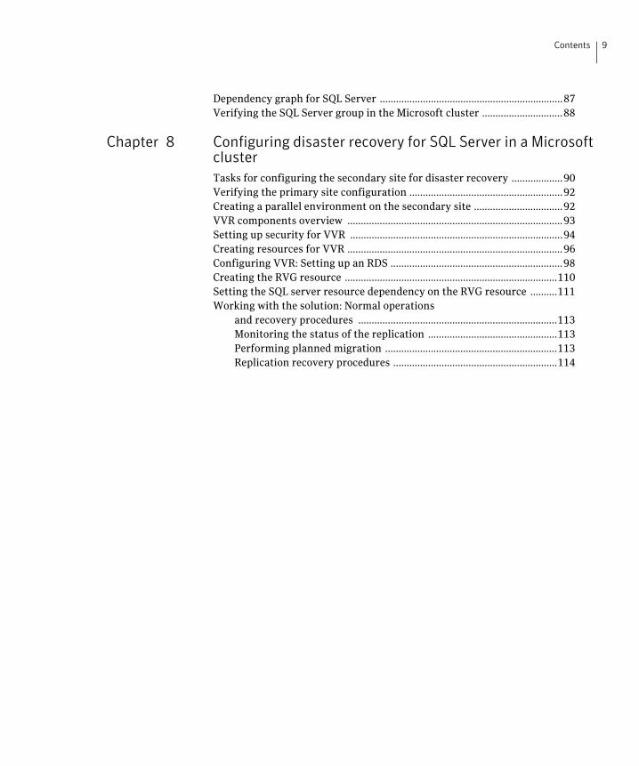
Dependency graph for SQL Server ....................................................................87Verifying the SQL Server group in the Microsoft cluster ..............................88
Chapter 8 Configuring disaster recovery for SQL Server in a Microsoft clusterTasks for configuring the secondary site for disaster recovery ...................90Verifying the primary site configuration .........................................................92Creating a parallel environment on the secondary site .................................92VVR components overview ................................................................................93Setting up security for VVR ...............................................................................94Creating resources for VVR ................................................................................96Configuring VVR: Setting up an RDS ................................................................98Creating the RVG resource ...............................................................................110Setting the SQL server resource dependency on the RVG resource ..........111Working with the solution: Normal operations
and recovery procedures ..........................................................................113Monitoring the status of the replication ................................................113Performing planned migration ................................................................113Replication recovery procedures .............................................................114

10 Contents
Chapter
1Introducing SFW solutions for a Microsoft cluster
This chapter covers the following topics:
■ About Microsoft clustering solutions with SFW
■ Advantages of using SFW in a Microsoft cluster
■ About high availability clusters
■ About campus clusters
■ About disaster recovery clusters
■ About the solutions guides
About Microsoft clustering solutions with SFWMicrosoft clustering may be used with Veritas Storage Foundation for Windows (SFW) to provide the following solutions:
■ High availability failover cluster in an active/passive configuration on the same site
■ Campus cluster, in a two-node configuration with each node on a separate site
■ Disaster recovery with a separate cluster on a secondary site, with replication support using Veritas Volume Replicator (VVR)
The example configurations in this guide do not include Dynamic Multi-pathing (DMP). For instructions on how to add DMP to a clustering configuration, see Veritas Storage Foundation and High Availability Solutions, Solutions Guide.

12 Introducing SFW solutions for a Microsoft clusterAdvantages of using SFW in a Microsoft cluster
Advantages of using SFW in a Microsoft clusterOne of the key advantages of using SFW with Microsoft clustering is the ability to create a mirrored quorum resource that adds fault tolerance to the quorum and protects the cluster. Microsoft clustering uses the quorum architecture, where the cluster database resides in the quorum resource. The quorum resource maintains the cluster database and critical recovery information in a recovery log.
Adding SFW to the configuration protects the quorum disk from being a single point of failure in the cluster because SFW provides dynamic volumes and software mirroring of the quorum device. If the quorum resource fails, the mirror takes over for the resource.
Using SFW also offers other advantages over using Microsoft clustering alone. SFW lets you add fault tolerance to your data volumes. Mirroring of log volumes is recommended, and a mirrored striped RAID layout is recommended for your data volumes. SFW also offers multiple disk groups, multiple mirrors, capacity management and Automatic Volume Growth, online storage migration, performance tuning, hot relocation, dirty region logging, RAID-5 logging, Dynamic Multi-pathing, and enhanced snapshot capabilities with FlashSnap.
About high availability clustersA high availability solution maintains continued functioning of applications in the event of computer failure, where data and applications are available using redundant software and hardware. High availability can refer to any software or hardware that provides fault tolerance, but generally it has become associated with clustering.
A cluster is a group of independent computers working together as a single system to ensure that mission-critical applications and resources are highly available. The cluster is managed as a single system, shares a common namespace, and is specifically designed to tolerate component failures and to support the addition or removal of components in a way that is transparent to users.
Clustered systems have several advantages, including fault tolerance, high availability, scalability, simplified management, and support for rolling upgrades.
In a high availability cluster with Veritas Storage Foundation for Windows, you configure dynamic cluster disk groups and volumes for the application on shared storage and install the application database and log to the appropriate SFW volumes.
Figure 1-1 shows a two-node high-availability configuration example.

13Introducing SFW solutions for a Microsoft clusterAbout campus clusters
Figure 1-1 High availability active-passive configuration
About campus clustersCampus clusters are multiple-node clusters that provide protection against disasters. The nodes can be located in separate buildings miles apart. Nodes are located within a single subnet and connected via a Fibre Channel SAN. Each node has its own storage array and contains mirrored data of the storage on the other array.
Typical campus clusters involve two sites; you can use more than two sites for additional redundancy.
This environment also provides a simpler solution for disaster recovery than a more elaborate Symantec disaster recovery environment with replication software; however, a campus cluster generally stretches a shorter distance than a replication-based solution depending on the hardware.
Both local clusters and campus clusters have SFW dynamic disk groups and volumes, but the volumes on each campus cluster node are mirrors of one another. Each disk group should contain the same number of disks on each site for the mirrored volumes.
Figure 1-2 shows a two-node campus cluster configuration example.

14 Introducing SFW solutions for a Microsoft clusterAbout disaster recovery clusters
Figure 1-2 Campus cluster configuration example
About disaster recovery clustersA typical disaster recovery configuration requires that you have a source host on the primary site and a destination host on the secondary site. The application data is stored on the primary site and replicated to the secondary site by using a tool such as the Veritas Volume Replicator. The primary site provides data and services during normal operation. If a disaster occurs on the primary site and its data is destroyed, a secondary host can take over the role of the primary host to make the data accessible. The application can be restarted on that host.
Using VVR with Microsoft clustering provides a replicated backup of your application data, which can be used for recovery after an outage or disaster. However, this solution does not provide the automated failover capability for disaster recovery that can be achieved using VVR with Veritas Cluster Server (VCS).

15Introducing SFW solutions for a Microsoft clusterAbout the solutions guides
In a typical clustered VVR configuration the primary site consists of two nodes, SYSTEM1 and SYSTEM2. Similarly the secondary setup consists of two nodes, SYSTEM3 and SYSTEM4. Each site has a clustered setup with the nodes set up appropriately for failover within the site. In a Microsoft cluster environment, each site has its own quorum volume.
If the the application on SYSTEM1 fails, the application comes online on node SYSTEM2 and begins servicing requests. From the user’s perspective there might be a small delay as the backup node comes online, but the interruption in effective service is minimal. When a failure occurs (for instance, after an earthquake that destroys the data center in which the primary site resides), the replication solution is activated. If there is a disaster at the primary site, SYSTEM3 at the secondary site takes over. The data that was replicated to the secondary site is used to restore the application services to clients.
Figure 1-3 shows a typical SFW VVR configuration with Microsoft clustering.
Figure 1-3 SFW-Microsoft clustering-VVR configuration
About the solutions guidesTable 1-1 shows the available Veritas Storage Foundation and High Availability Solutions solutions guides for SQL Server. Guides are also available for

16 Introducing SFW solutions for a Microsoft clusterAbout the solutions guides
Microsoft Exchange, Enterprise Vault, SharePoint Server, and for additional application solutions.

Chapter
2Workflows for deploying SQL Server withSFW in a Microsoft cluster
This chapter covers the following topics:
■ Workflow for a high availability (HA) configuration
■ Workflow for a campus cluster configuration
■ Workflow for a disaster recovery configuration
■ Using the Solutions Configuration Center workflow

18 Workflows for deploying SQL Server with SFW in a Microsoft clusterWorkflow for a high availability (HA) configuration
Workflow for a high availability (HA) configurationYou can install and configure Storage Foundation for Windows (SFW) and SQL Server in a Microsoft cluster for high availability on a single site.
Table 2-1 show the process for deploying SQL Server with SFW in a Microsoft high-availability cluster.
Table 2-1 Process for deploying SQL Server with SFW in a Microsoft high-availability cluster
Action Description
Verify hardware and software prerequisites
See “Requirements for deploying SQL Server with SFW in a Microsoft cluster” on page 30.
Understand the configuration See “Planning your high availability configuration” on page 34.
Configure the storage hardware and network
■ Set up the storage hardware for a cluster environment.
■ Verify the DNS entries for the systems on which SQL will be installed.
See “Configuring the storage hardware and network” on page 48.
Establish a Microsoft cluster Establish the cluster before installing SFW.
See “Establishing a Microsoft failover cluster” on page 49.
Install SFW with the Microsoft Failover Cluster option
Perform a rolling installation.
See “Installing SFW with Microsoft Failover Cluster option” on page 51.
Ensure that you select the following options during installation of SFW:
■ Select the option to install SFW.
■ On the product options screen, select the option to install Cluster Option for Microsoft Failover Cluster.
■ Verify that the Veritas Storage Foundation for Windows (Client Components) check box is checked, to install the client component.
■ If you plan to set up a secondary site for disaster recovery with VVR, install the Veritas Volume Replicator option.

19Workflows for deploying SQL Server with SFW in a Microsoft clusterWorkflow for a high availability (HA) configuration
Configure and manage disk groups and volumes
■ Use the VEA console to create disk groups and volumes for the application and for the quorum resource.See “Tasks for configuring SFW storage” on page 53.
Note: Setting up a Microsoft failover cluster creates physical disk resources for all the basic disks on the shared bus. To use these disks when you create your SFW cluster disk groups, you must first remove the physical disk resources from the cluster. Otherwise, a reservation conflict occurs.
Implement a dynamic mirrored quorum resource
■ Create a dynamic cluster disk group with a mirrored volume for the quorum disks.
■ Create a Volume Manager Disk Group (VMDG) resource for the quorum disk group.
■ Change the cluster quorum resource to the dynamic mirrored quorum resource.
See “Tasks for implementing a dynamic mirrored quorum resource” on page 77.
Create the SQL virtual server resource group
■ Create a SQL Server resource group in the cluster.
■ Add the VMDG disk group resource(s).
See “Creating the resource group for the SQL Server instance” on page 83.
Table 2-1 Process for deploying SQL Server with SFW in a Microsoft high-availability cluster (Continued)
Action Description

20 Workflows for deploying SQL Server with SFW in a Microsoft clusterWorkflow for a campus cluster configuration
Workflow for a campus cluster configurationYou can install and configure Storage Foundation for Windows (SFW) and SQL Server in a Microsoft campus cluster.
This configuration workflow describes a two-node campus cluster with each node at a separate site.
The procedures for setting up a campus cluster are nearly the same as those for local clusters, with the following differences:
■ A campus cluster has the nodes located in separate buildings. Therefore, the hardware setup requires SAN interconnects that allow these connections.
■ In a campus cluster, each node has its own storage array rather than having a shared storage array between the two clusters.
■ Both local clusters and campus clusters have SFW dynamic disk groups and volumes, but the volumes on each campus cluster node are mirrors of one
Install SQL Server ■ Review the prerequisites for installationSee “Prerequisites for installing SQL Server” on page 84.
■ Mount the disk group and volumes created for the data files on the node where you install.See “Managing disk group and volumes” on page 73.
■ Install the software. Ensure that you install the data files to the path of the dynamic volume on shared storage.See “Installing SQL Server 2005 in an SFW environment” on page 85.See “Installing SQL Server 2008, 2008 R2, or 2012 in an SFW environment” on page 86.
■ Verify the resource dependencies.See “Dependency graph for SQL Server” on page 87.
Verify the cluster configuration
Move the online SQL Server cluster group to the second node and back to the first node.
See “Verifying the SQL Server group in the Microsoft cluster” on page 88.
Table 2-1 Process for deploying SQL Server with SFW in a Microsoft high-availability cluster (Continued)
Action Description

21Workflows for deploying SQL Server with SFW in a Microsoft clusterWorkflow for a campus cluster configuration
another. Each disk group must contain the same number of disks on each site for the mirrored volumes.
■ For campus clusters, you enable site allocation, assigning disks to one or the other campus cluster sites.
Table 2-2 shows the process for deploying SQL Server with SFW in a Microsoft campus cluster.
Table 2-2 Process for deploying SQL Server with SFW in a Microsoft campus cluster
Action Description
Verify hardware and software prerequisites
See “Planning your campus cluster configuration” on page 37.
Understand the configuration See “Planning your campus cluster configuration” on page 37.
Configure the storage hardware and network
■ Set up the storage hardware for a cluster environment.
■ Verify the DNS entries for the systems on which SQL will be installed.
See “Configuring the storage hardware and network” on page 48.
Establish a Microsoft cluster See “Establishing a Microsoft failover cluster” on page 49.
Connect the two campus cluster nodes after setting up the Microsoft cluster.
See “Establishing a Microsoft failover cluster” on page 49.
Install SFW with the Microsoft Failover Cluster option
Perform a rolling installation.
See “Installing SFW with Microsoft Failover Cluster option” on page 51.
Ensure that you select the following options during SFW installation:
■ Select the option to install SFW.
■ On the product options screen, select the option to install Cluster Option for Microsoft Failover Cluster.
■ Verify that the Veritas Storage Foundation for Windows (Client Components) check box is checked, to install the client component.

22 Workflows for deploying SQL Server with SFW in a Microsoft clusterWorkflow for a campus cluster configuration
Configure and manage disk groups and volumes
■ Use the VEA console to create disk groups and volumes for the application and for the quorum resource.See “Tasks for configuring SFW storage” on page 53.Ensure that the disk group you configure on each site contains the same number of disks and that you configure mirrored volumes.See “Considerations when creating disk groups and volumes for a campus cluster” on page 60.After creating the disk group, add the disks to a campus cluster site to enable site allocation.See“Adding disks to campus cluster sites” on page 65 .
Note: Setting up a Microsoft failover cluster creates physical disk resources for all the basic disks on the shared bus. To use these disks when you create your SFW cluster disk groups, you must first remove the physical disk resources from the cluster. Otherwise, a reservation conflict occurs.
Implement a dynamic mirrored quorum resource
■ Create a dynamic cluster disk group with a mirrored volume for the quorum disks.
■ Create a Volume Manager Disk Group (VMDG) resource for the quorum disk group.
■ Change the cluster quorum resource to the dynamic mirrored quorum resource.
See “Tasks for implementing a dynamic mirrored quorum resource” on page 77.
Create the SQL virtual server group
■ Create a SQL Server cluster group.
■ Add the VMDG disk group resource(s).
See “Creating the resource group for the SQL Server instance” on page 83.
Table 2-2 Process for deploying SQL Server with SFW in a Microsoft campus cluster (Continued)
Action Description
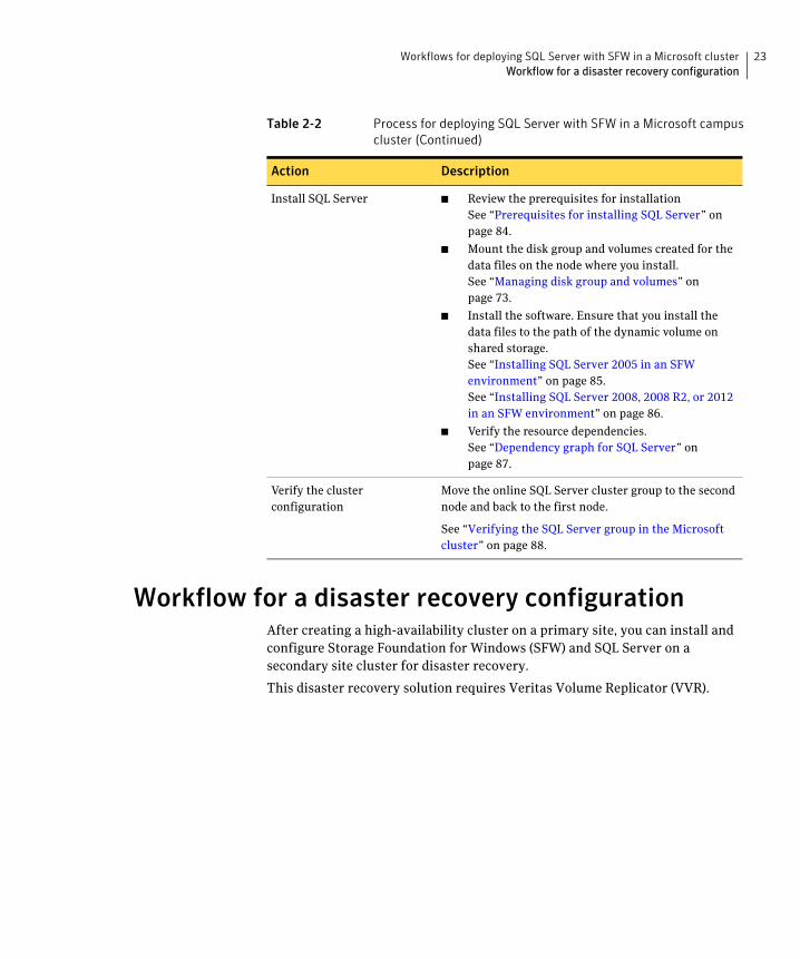
23Workflows for deploying SQL Server with SFW in a Microsoft clusterWorkflow for a disaster recovery configuration
Workflow for a disaster recovery configurationAfter creating a high-availability cluster on a primary site, you can install and configure Storage Foundation for Windows (SFW) and SQL Server on a secondary site cluster for disaster recovery.
This disaster recovery solution requires Veritas Volume Replicator (VVR).
Install SQL Server ■ Review the prerequisites for installationSee “Prerequisites for installing SQL Server” on page 84.
■ Mount the disk group and volumes created for the data files on the node where you install.See “Managing disk group and volumes” on page 73.
■ Install the software. Ensure that you install the data files to the path of the dynamic volume on shared storage.See “Installing SQL Server 2005 in an SFW environment” on page 85.See “Installing SQL Server 2008, 2008 R2, or 2012 in an SFW environment” on page 86.
■ Verify the resource dependencies.See “Dependency graph for SQL Server” on page 87.
Verify the cluster configuration
Move the online SQL Server cluster group to the second node and back to the first node.
See “Verifying the SQL Server group in the Microsoft cluster” on page 88.
Table 2-2 Process for deploying SQL Server with SFW in a Microsoft campus cluster (Continued)
Action Description

24 Workflows for deploying SQL Server with SFW in a Microsoft clusterWorkflow for a disaster recovery configuration
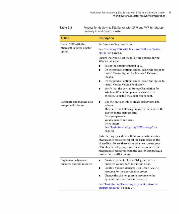
Table 2-3 shows the process for deploying the disaster recover configuration.
Table 2-3 Process for deploying SQL Server with SFW and VVR for disaster recovery in a Microsoft cluster
Action Description
Ensure that you have set up the primary site for high availability, including the required options for disaster recovery
For details on setting up high-availability on the primary site, see “Workflow for a high availability (HA) configuration” on page 18.
For a disaster recovery configuration, you must install the Veritas Volume Replicator option on the primary as well as the secondary site.
Ensure that you are using static IP addresses as required for VVR.
Review the prerequisites and planning information
Verify the prerequisites on the secondary site.
See “Requirements for deploying SQL Server with SFW in a Microsoft cluster” on page 30.
Note: If the DR site is on a different network segment, ensure that you allocate two IP addresses for the virtual server, one for the primary site and one for the DR site.
Understand the DR configuration.
See “Planning your disaster recovery configuration” on page 43.
Review how to create a parallel high availability configuration on the secondary site
Ensure that you follow the secondary site requirements and guidelines for IP addresses, disk groups and volumes, the SQL Server resource group, and SQL Server installation.
See “Creating a parallel environment on the secondary site” on page 92.
Configure the storage hardware and network
■ Set up the storage hardware for a cluster environment.
■ Verify the DNS entries for the systems on which SQL will be installed.
See “Configuring the storage hardware and network” on page 48.
Establish a Microsoft cluster Establish the cluster before installing SFW.
See “Establishing a Microsoft failover cluster” on page 49.
25Workflows for deploying SQL Server with SFW in a Microsoft clusterWorkflow for a disaster recovery configuration
Install SFW with the Microsoft Failover Cluster option
Perform a rolling installation.
See “Installing SFW with Microsoft Failover Cluster option” on page 51.
Ensure that you select the following options during SFW installation:
■ Select the option to install SFW.
■ On the product options screen, select the option to install Cluster Option for Microsoft Failover Cluster.
■ On the product options screen, select the option to install Veritas Volume Replicator.
■ Verify that the Veritas Storage Foundation for Windows (Client Components) check box is checked, to install the client component.
Configure and manage disk groups and volumes
■ Use the VEA console to create disk groups and volumes.Make sure the following is exactly the same as the cluster on the primary site:Disk group nameVolume names and sizes Drive lettersSee “Tasks for configuring SFW storage” on page 53.
Note: Setting up a Microsoft failover cluster creates physical disk resources for all the basic disks on the shared bus. To use these disks when you create your SFW cluster disk groups, you must first remove the physical disk resources from the cluster. Otherwise, a reservation conflict occurs.
Implement a dynamic mirrored quorum resource
■ Create a dynamic cluster disk group with a mirrored volume for the quorum disks.
■ Create a Volume Manager Disk Group (VMDG) resource for the quorum disk group.
■ Change the cluster quorum resource to the dynamic mirrored quorum resource.
See “Tasks for implementing a dynamic mirrored quorum resource” on page 77.
Table 2-3 Process for deploying SQL Server with SFW and VVR for disaster recovery in a Microsoft cluster
Action Description

26 Workflows for deploying SQL Server with SFW in a Microsoft clusterWorkflow for a disaster recovery configuration
Create the SQL virtual server group
■ Create a SQL Server cluster group. Ensure that it has the same name as on the primary site.
■ Add the VMDG disk group resource(s).
See “Creating the resource group for the SQL Server instance” on page 83.
Install SQL Server Before starting the SQL installation on the secondary site, note the following requirements:
■ Make sure that you take the SQL Server Network Name resource offline on the primary site. This will also offline the dependent resources.
■ Mount the disk group and volumes created for the data files on the node where you install.
■ During installation, specify the same name for the SQL virtual server as that on the primary site.
■ Ensure that you install the data files to the path of the dynamic volume on shared storage.
See “Installing SQL Server” on page 85.
Verify the cluster configuration
Move the online SQL Server cluster group to the second node and back to the first node.
See “Verifying the SQL Server group in the Microsoft cluster” on page 88.
Understand the VVR components
See “VVR components overview” on page 93.
Set up security for VVR Set up the security for VVR on all nodes on both the primary and secondary sites.
See “Setting up security for VVR” on page 94.
Create the cluster resources for VVR
■ Create an IP address for the Replicated Volume Group (RVG).
■ Create a Network Name resource for the Replicated Volume Group (RVG).
See “Creating resources for VVR” on page 96.
Set up an RDS Create a replicated data set (RDS) using the VVR wizard.
See “Configuring VVR: Setting up an RDS” on page 98.
Table 2-3 Process for deploying SQL Server with SFW and VVR for disaster recovery in a Microsoft cluster
Action Description

27Workflows for deploying SQL Server with SFW in a Microsoft clusterUsing the Solutions Configuration Center workflow
Using the Solutions Configuration Center workflowThe SFW HA product includes a Solutions Configuration Center for various application and configuration solutions.
For Microsoft clustering, the campus cluster configuration solution is available as a workflow on the Configuration Center, with online help linking to the appropriate topics.
To use the Microsoft campus cluster workflow in the Solutions Configuration Center
1 Start the Solutions Configuration Center in one of the following ways:
■ Click Start > All Programs > Symantec > Veritas Storage Foundation > Solutions Configuration Center.
■ Click Start > Run and type scc.
2 Click to expand Solutions for Microsoft SQL Server.
3 Click to expand the Microsoft Campus Cluster workflow.
Create the RVG resource (primary and secondary sites)
Create the RVG resource on both primary and secondary sites.
See “Creating the RVG resource” on page 110.
Set up the SQL Server resource dependencies
Change the SQL Server resource properties so that it depends on the RVG resource instead of the Volume Manager Disk Group resource.
See “Setting the SQL server resource dependency on the RVG resource” on page 111.
Table 2-3 Process for deploying SQL Server with SFW and VVR for disaster recovery in a Microsoft cluster
Action Description

28 Workflows for deploying SQL Server with SFW in a Microsoft clusterUsing the Solutions Configuration Center workflow
Chapter
3Planning for deploying SQL Server withSFW in a Microsoft cluster
This chapter covers the following topics:
■ Requirements for deploying SQL Server with SFW in a Microsoft cluster
■ Planning your high availability configuration
■ Planning your campus cluster configuration
■ Planning your disaster recovery configuration
30 Planning for deploying SQL Server with SFW in a Microsoft clusterRequirements for deploying SQL Server with SFW in a Microsoft cluster
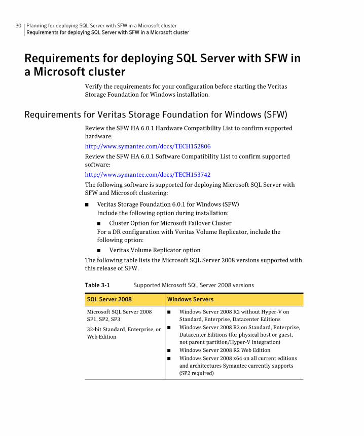
Requirements for deploying SQL Server with SFW in a Microsoft cluster
Verify the requirements for your configuration before starting the Veritas Storage Foundation for Windows installation.
Requirements for Veritas Storage Foundation for Windows (SFW)Review the SFW HA 6.0.1 Hardware Compatibility List to confirm supported hardware:
http://www.symantec.com/docs/TECH152806
Review the SFW HA 6.0.1 Software Compatibility List to confirm supported software:
http://www.symantec.com/docs/TECH153742
The following software is supported for deploying Microsoft SQL Server with SFW and Microsoft clustering:
■ Veritas Storage Foundation 6.0.1 for Windows (SFW)
Include the following option during installation:
■ Cluster Option for Microsoft Failover Cluster
For a DR configuration with Veritas Volume Replicator, include the following option:
■ Veritas Volume Replicator option
The following table lists the Microsoft SQL Server 2008 versions supported with this release of SFW.
Table 3-1 Supported Microsoft SQL Server 2008 versions
SQL Server 2008 Windows Servers
Microsoft SQL Server 2008 SP1, SP2, SP3
32-bit Standard, Enterprise, or Web Edition
■ Windows Server 2008 R2 without Hyper-V on Standard, Enterprise, Datacenter Editions
■ Windows Server 2008 R2 on Standard, Enterprise, Datacenter Editions (for physical host or guest, not parent partition/Hyper-V integration)
■ Windows Server 2008 R2 Web Edition
■ Windows Server 2008 x64 on all current editions and architectures Symantec currently supports (SP2 required)

31Planning for deploying SQL Server with SFW in a Microsoft clusterRequirements for deploying SQL Server with SFW in a Microsoft cluster
The following table lists the Microsoft SQL Server 2008 R2 versions supported with this release of SFW.
Microsoft SQL Server 2008 SP1, SP2, SP3
64-bit Standard, Enterprise, or Web Edition
■ Windows Server 2008 x64 (for AMD64 or Intel EM64T): Standard, Enterprise, or Datacenter Edition
■ Windows Server 2008 R2 without Hyper-V on Standard, Enterprise, Datacenter Editions
■ Windows Server 2008 R2 on Standard, Enterprise, Datacenter Editions (for physical host or guest, not parent partition/Hyper-V integration)
■ Windows Server 2008 R2 Web Edition
■ Windows Server 2008 x64 on all current editions and architectures Symantec currently supports (SP2 required)
Table 3-2 Supported Microsoft SQL Server 2008 R2 versions
SQL Server 2008 R2 Windows Servers
Microsoft SQL Server 2008 R2
RTM or SP1
32-bit Standard, Enterprise, Datacenter Edition
■ Windows Server 2008 R2 without Hyper-V on Standard, Enterprise, Datacenter Editions
■ Windows Server 2008 R2 on Standard, Enterprise, Datacenter Editions (for physical host or guest, not parent partition/Hyper-V integration)
■ Windows Server 2008 R2 Web Edition
■ Windows Server 2008 x64 on all current editions and architectures Symantec currently supports (SP2 required)
Microsoft SQL Server 2008 R2
RTM or SP1
64-bit Standard, Enterprise, Datacenter Edition
■ Windows Server 2008 x64 (for AMD64 or Intel EM64T): Standard, Enterprise, or Datacenter Edition
■ Windows Server 2008 R2 without Hyper-V on Standard, Enterprise, Datacenter Editions
■ Windows Server 2008 R2 on Standard, Enterprise, Datacenter Editions (for physical host or guest, not parent partition/Hyper-V integration)
■ Windows Server 2008 R2 Web Edition
■ Windows Server 2008 x64 on all current editions and architectures Symantec currently supports (SP2 required)
Table 3-1 Supported Microsoft SQL Server 2008 versions (Continued)
SQL Server 2008 Windows Servers

32 Planning for deploying SQL Server with SFW in a Microsoft clusterRequirements for deploying SQL Server with SFW in a Microsoft cluster
The following table lists the Microsoft SQL Server 2005 versions supported with this release of SFW.
Table 3-3 Microsoft SQL Server 2005 supported environments
Microsoft SQL Server 2005 Window Servers
Microsoft SQL Server 2005
SP2, SP3, or SP4
32-bit Standard or Enterprise Edition
■ Windows Server 2008 R2 without Hyper-V on Standard, Enterprise, Datacenter Editions
■ Windows Server 2008 R2 on Standard, Enterprise, Datacenter Editions (for physical host or guest, not parent partition/Hyper-V integration)
■ Windows Server 2008 R2 Web Edition
■ Windows Server 2008 x64 on all current editions and architectures Symantec currently supports (SP2 required)
Microsoft SQL Server 2005
SP1, SP2, SP3. or SP4
64-bit Standard or Enterprise Edition
■ Windows Server 2008 x64 (for AMD64 or Intel EM64T): Standard, Enterprise, or Datacenter Edition
■ Windows Server 2008 R2 without Hyper-V on Standard, Enterprise, Datacenter Editions
■ Windows Server 2008 R2 on Standard, Enterprise, Datacenter Editions (for physical host or guest, not parent partition/Hyper-V integration)
■ Windows Server 2008 R2 Web Edition
■ Windows Server 2008 x64 on all current editions and architectures Symantec currently supports (SP2 required)

33Planning for deploying SQL Server with SFW in a Microsoft clusterRequirements for deploying SQL Server with SFW in a Microsoft cluster
Disk space requirementsThe following table summarizes disk space requirements for SFW.
System requirementsRefer to Microsoft documentation for Microsoft cluster requirements. Use the following system requirements as a guideline for SFW with SQL Server in a Microsoft cluster:
■ One CD-ROM drive accessible to the system on which you are installing SFW.
■ Each system requires 1 GB of RAM for SFW.
■ Each system requires a minimum of 512 MB of RAM for SQL Server; refer to the Microsoft documentation for more information.
■ SCSI or Fibre Channel host bus adapters (HBAs) can be used to access shared storage.
■ Microsoft clustering requires at least two network adapters per system (one NIC to connect each system to the public network, and one NIC for the private network on each system). Symantec recommends using three network adapters (two NICs exclusively for the private network and one for the public network). Route each private NIC through a separate hub or switch to avoid single points of failure.
■ Using static IP addresses for the public network and private network cards is highly recommended and is required for a VVR configuration. You also need a static IP address for the cluster itself. Verify that name resolution is configured for each node.
■ Verify that the DNS and Active Directory Services are available. Make sure a reverse lookup zone exists in the DNS. Refer to the Microsoft SQL Server documentation for instructions on creating a reverse lookup zone.
■ Microsoft clustering requires at least two disks for SQL: one for SQL database files and one for SQL log files. For SQL Server 2008, 2008 R2, or 2012, if FILESTREAM is implemented, a separate disk is recommended for the FILESTREAM filegroup.
Table 3-4 Disk space requirements
Installation options Required disk space
SFW + all options 1124 MB
Client components 632 MB

34 Planning for deploying SQL Server with SFW in a Microsoft clusterPlanning your high availability configuration
■ For a campus cluster configuration, the following applies:
■ The configuration requires two sites with a storage array for each site, with an equal number of disks at each site for the mirrored volumes.
■ Interconnects between the clusters are required for the storage and the network.
■ Each system in a Microsoft cluster must be in the same Windows Server domain and must be using the same operating system version.
Additional installation requirementsSFW requires administrator privileges to install the software.
To install SFW, a Microsoft cluster must be running. Before you install SFW, you must set up the hardware and install the operating system and Microsoft clustering feature on all systems and establish the Microsoft cluster.
Installing SFW requires a reboot, but a reboot on the active cluster node causes it to fail over. Therefore, use a “rolling install” procedure to install SFW first on the inactive cluster node. Then move the cluster resources to the other node and install on the now inactive node.
See “Installing SFW with Microsoft Failover Cluster option” on page 51.
Note: You can install the SFW option for Microsoft Failover Cluster on a machine that is not a member of a Microsoft cluster. However, if that machine becomes the first node in a Microsoft cluster, the Volume Manager Disk Group resource type must be manually registered. For more information, see the Veritas Storage Foundation and High Availability Solutions Installation and Upgrade Guide.
Planning your high availability configurationYou can configure Storage Foundation for Windows (SFW) and SQL Server in a Microsoft cluster for high availability on a single site.
In the example high availability configuration, you create a virtual server in an active/passive SQL Server configuration on a Microsoft cluster. The active node of the cluster hosts the virtual server. The second node is a dedicated redundant server able to take over and host the virtual server in the event of a failure on the active node. In a high availability configuration both nodes are located on the same site.
Figure 3-1 illustrates a typical two-node active/passive configuration.

35Planning for deploying SQL Server with SFW in a Microsoft clusterPlanning your high availability configuration
Figure 3-1 High availability active/passive configuration
Some key points about the configuration:
■ The SQL virtual server is configured on the active node (SYSTEM1). If SYSTEM1 fails, SYSTEM2 becomes the active node and the SQL virtual server comes online on SYSTEM2.
■ One or more application virtual servers can exist in a cluster, but each server must be managed by a separate application group configured with a distinct set of nodes in the cluster.
■ The SQL databases are configured on the shared storage on volumes contained in one or more cluster disk groups.
■ SFW enables you to create a dynamic mirrored quorum. If the quorum resource fails, the mirror takes over for the resource.
In this configuration, Symantec recommends creating a three-way mirror for the quorum to provide additional fault tolerance. If possible, do not use the disks assigned to the quorum for any other purpose.
■ SFW enables you to add fault-tolerance to data volumes. Symantec recommends mirroring log volumes and a mirrored striped RAID layout for data volumes.
During the configuration process you will create virtual IP addresses for the following:
■ Cluster IP address, used by Microsoft cluster
■ SQL virtual server IP address, which should be the same on all nodes
You should have these IP addresses available before you start deploying your environment.

36 Planning for deploying SQL Server with SFW in a Microsoft clusterPlanning your high availability configuration
Sample high availability configuration for SQL Server with SFWThe example configuration includes the dynamic mirrored quorum and requires setting up two or more dynamic cluster disk groups in SFW—one or more cluster disk groups for the application and data and one for the dynamic mirrored quorum.
The following names describe the objects created and used during the installation and configuration.
For more information on disk group and volume configuration, see “Planning for SFW cluster disk groups and volumes” on page 54.
Configuring the quorum device for high availabilityThe proper configuration of a quorum device is critical to providing the highest availability with SFW storage.
Although a single basic disk used as a physical disk resource can serve as the Microsoft clustering quorum device, this introduces a nonredundant component into an otherwise highly available system.
Name Object
SYSTEM1 & SYSTEM2 server names
SQL_GROUP Microsoft SQL Server resource group
SQLCLUST Microsoft cluster for SQL Server high availability
SQLVS Microsoft SQL Server virtual server
INST1 Microsoft SQL Server instance name
INST1_DG disk group for Microsoft SQL Server volumes
INST1_SYS_FILES volume for Microsoft SQL Server system data files
INST1_DB1_VOL volume for storing a Microsoft SQL Server user-defined database
INST1_DB1_LOG volume for storing a Microsoft SQL Server user-defined database log file
INST1_DB1_FS volume for storing FILESTREAM filegroups (on SQL Server 2008, 2008 R2, or 2012, if FILESTREAM is implemented)
QUORUM_DG disk group for quorum volume
SQL_QRM volume for storing the Microsoft cluster quorum

37Planning for deploying SQL Server with SFW in a Microsoft clusterPlanning your campus cluster configuration
In general, a disk group containing a dedicated, three-way mirrored volume makes an ideal quorum device. Such a device tolerates two disk failures, because it is mirrored, and server and interconnect failures, because SFW can import it when the disks and at least one server are running.
For a server to take ownership of a disk group containing the cluster quorum device, SFW must successfully import the disk group, and obtain SCSI reservations on more than half of its disks. Disk groups containing odd numbers of disks are best for use as quorum devices because of this behavior.
An SFW cluster disk group containing a volume used as a quorum device should contain that volume only. Any other volumes in that disk group fail over whenever the quorum device changes ownership.
Planning your campus cluster configurationThe procedures for setting up a campus cluster are nearly the same as those for local clusters, with the following differences:
■ A campus cluster has the nodes located in separate buildings. Therefore, the hardware setup requires SAN interconnects that allow these connections.
■ In a campus cluster, each node has its own storage array rather than having a shared storage array between the two clusters.
■ Both local clusters and campus clusters have SFW dynamic disk groups and volumes, but the volumes on each campus cluster node are mirrors of one another.
■ Each disk group must contain the same number of disks on each site for the mirrored volumes.
For more information on disk group and volume configuration, see “Planning for SFW cluster disk groups and volumes” on page 54.
Although a campus cluster setup with Microsoft clustering can work without Storage Foundation for Windows, SFW provides key advantages over using Microsoft clustering alone. Through a dynamic mirrored volume that functions on multiple disks across multiple sites, SFW protects the quorum resource in the cluster from being the single point of failure in the cluster.
Most customers use hardware RAID to protect the quorum disk, but that does not work when a natural disaster takes down the primary node and its attached storage. If the quorum resource is lost to the cluster, the cluster fails, because none of the cluster servers can gain control of the quorum resource and ultimately the cluster. Microsoft clustering alone cannot provide fault tolerance to the quorum disk.

38 Planning for deploying SQL Server with SFW in a Microsoft clusterPlanning your campus cluster configuration
Figure 3-2 shows a Microsoft cluster campus cluster configuration with mirrored storage across clusters and a mirrored quorum resource. The 4-way mirrored quorum has an extra set of mirrors for added redundancy.
Figure 3-2 Typical campus clustering configuration
39Planning for deploying SQL Server with SFW in a Microsoft clusterPlanning your campus cluster configuration
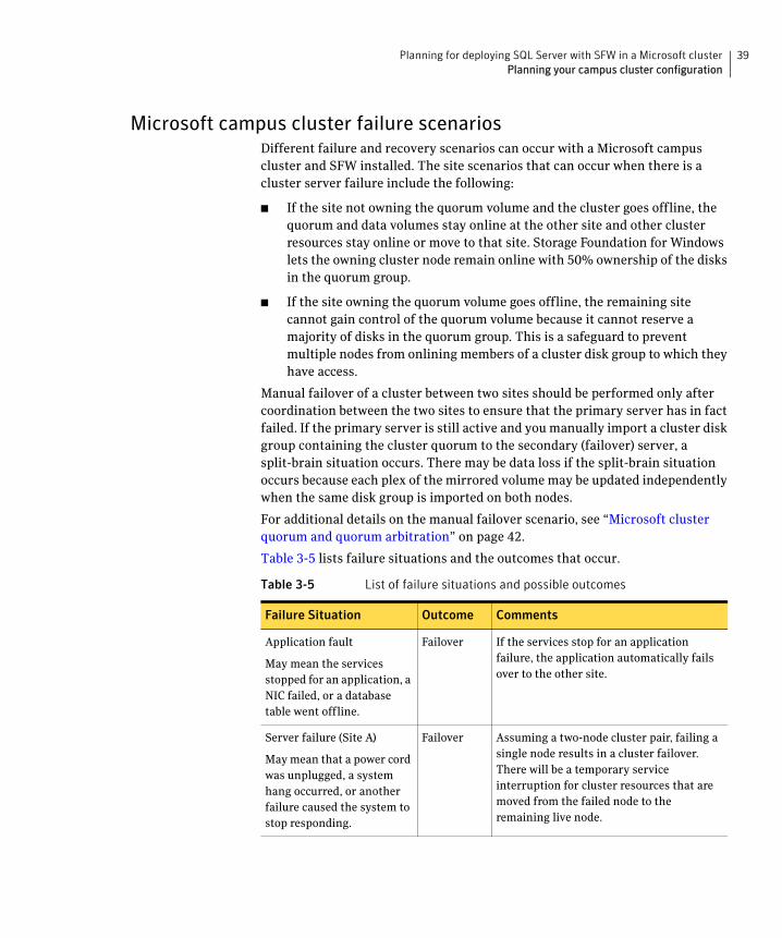
Microsoft campus cluster failure scenariosDifferent failure and recovery scenarios can occur with a Microsoft campus cluster and SFW installed. The site scenarios that can occur when there is a cluster server failure include the following:
■ If the site not owning the quorum volume and the cluster goes offline, the quorum and data volumes stay online at the other site and other cluster resources stay online or move to that site. Storage Foundation for Windows lets the owning cluster node remain online with 50% ownership of the disks in the quorum group.
■ If the site owning the quorum volume goes offline, the remaining site cannot gain control of the quorum volume because it cannot reserve a majority of disks in the quorum group. This is a safeguard to prevent multiple nodes from onlining members of a cluster disk group to which they have access.
Manual failover of a cluster between two sites should be performed only after coordination between the two sites to ensure that the primary server has in fact failed. If the primary server is still active and you manually import a cluster disk group containing the cluster quorum to the secondary (failover) server, a split-brain situation occurs. There may be data loss if the split-brain situation occurs because each plex of the mirrored volume may be updated independently when the same disk group is imported on both nodes.
For additional details on the manual failover scenario, see “Microsoft cluster quorum and quorum arbitration” on page 42.
Table 3-5 lists failure situations and the outcomes that occur.
Table 3-5 List of failure situations and possible outcomes
Failure Situation Outcome Comments
Application fault
May mean the services stopped for an application, a NIC failed, or a database table went offline.
Failover If the services stop for an application failure, the application automatically fails over to the other site.
Server failure (Site A)
May mean that a power cord was unplugged, a system hang occurred, or another failure caused the system to stop responding.
Failover Assuming a two-node cluster pair, failing a single node results in a cluster failover. There will be a temporary service interruption for cluster resources that are moved from the failed node to the remaining live node.

40 Planning for deploying SQL Server with SFW in a Microsoft clusterPlanning your campus cluster configuration
Server failure (Site B)
May mean that a power cord was unplugged, a system hang occurred, or another failure caused the system to stop responding.
No interruption of service.
Failure of the passive site (Site B) does not interrupt service to the active site (Site A).
Partial SAN network failure
May mean that SAN fiber channel cables were disconnected to Site A or Site B Storage.
No interruption of service.
Assuming that each of the cluster nodes has some type of Dynamic Multi-pathing (DMP) solution, removing one SAN fiber cable from a single cluster node should not effect any cluster resources running on that node, because the underlying DMP solution should seamlessly handle the SAN fiber path failover.
Private IP Heartbeat Network Failure
May mean that the private NICs or the connecting network cables failed.
No interruption of service.
With the standard two-NIC configuration for a cluster node, one NIC for the public cluster network and one NIC for the private heartbeat network, disabling the NIC for the private heartbeat network should not effect the cluster software and the cluster resources, because the cluster software will simply route the heartbeat packets through the public network.
Public IP Network Failure
May mean that the public NIC or LAN network has failed.
Failover.
Mirroring continues.
When the public NIC on the active node, or public LAN fails, clients cannot access the active node, and failover occurs.
Public and Private IP or Network Failure
May mean that the LAN network, including both private and public NIC connections, has failed.
No interruption of service. No Public LAN access.
Mirroring continues.
The site that owned the quorum resource right before the “network partition” remains as owner of the quorum resource, and is the only surviving cluster node. The cluster software running on the other cluster node self-terminates because it has lost the cluster arbitration for the quorum resource.
Table 3-5 List of failure situations and possible outcomes (Continued)
Failure Situation Outcome Comments

41Planning for deploying SQL Server with SFW in a Microsoft clusterPlanning your campus cluster configuration
Lose Network Connection (SAN & LAN), failing both heartbeat and connection to storage
May mean that all network and SAN connections are severed, for example if a single pipe is used between buildings for the Ethernet and storage.
No interruption of service. Disks on the same node are functioning. Mirroring is not working.
The node/site that owned the quorum resource right before the “network partition” remains as owner of the quorum resource, and is the only surviving cluster node. The cluster software running on the other cluster node self-terminates because it has lost the cluster arbitration for the quorum resource. By default Microsoft clustering clussvc service will try to auto-start every minute, so after LAN/SAN communication has been re-established, Microsoft clustering clussvc will auto-start and will be able to re-join the existing cluster.
Storage Array failure on Site A, or on Site B
May mean that a power cord was unplugged, or a storage array failure caused the array to stop responding.
No interruption of service. Disks on the same node are functioning. Mirroring is not working.
The campus cluster is divided equally between two sites with one array at each site. Completely failing one storage array should not effect on the cluster or any cluster resources that are currently online. However, you will not be able to move any cluster resources between nodes after this storage failure, because neither node will be able to obtain a majority of disks within the cluster disk group.
Site A failure (power)
Means that all access to site A, including server and storage, is lost.
Manual failover.
If the failed site contains the cluster node that owned the quorum resource, then the overall cluster would be offline and cannot be onlined on the remaining live site without manual intervention.
Site B failure (power)
Means that all access to site B, including server and storage, is lost.
No interruption of service. Disks on the same node are functioning. Mirroring is not working.
If the failed site did not contain the cluster node that owned the quorum resource, then the cluster would still be alive with whatever cluster resources that were online on that node right before the site failure.
Table 3-5 List of failure situations and possible outcomes (Continued)
Failure Situation Outcome Comments

42 Planning for deploying SQL Server with SFW in a Microsoft clusterPlanning your campus cluster configuration
Microsoft cluster quorum and quorum arbitrationThis section explains the quorum and quorum arbitration in Microsoft clusters.
QuorumThe quorum resource maintains the cluster database, as well as critical recovery information, in a recovery log. The quorum resource must be available to all nodes through a SCSI or Fibre Channel bus. With Microsoft clustering alone, the quorum disk must be located on a single physical disk. However, with SFW, the quorum disk can be a mirrored volume that spans multiple disks and cluster nodes.
The quorum resource also determines ownership of the cluster. When a node that is controlling the cluster goes offline, other nodes use a challenge/defense protocol to determine which node can have control of the quorum resource and the cluster.
Cluster ownership of the quorum resourceThe Microsoft clustering challenge/defense protocol uses a low-level bus reset of the SCSI buses between the machines to attempt to gain control of the quorum resource.
After a SCSI bus reset, the reservation that each server had been holding on the quorum disk is lost. Each server has about 10 seconds to re-establish that reservation, which would in turn let the other servers know that it is still functioning, even though the other servers would not necessarily be able to communicate with it.
If the active cluster server does not re-establish the SCSI reservation on the quorum resource within the time limit, the applications that were on the server transfer to the server that establishes the SCSI reservation first. The new server servicing the application may now be a bit slower, but clients still get their applications serviced. The IP (Internet Protocol) address and network names move, applications are reconstituted according to the defined dependencies, and clients are still serviced, without any question as to the state of the cluster.
The challenge/defense protocol is more complex when the quorum device is a volume in a Storage Foundation for Windows disk group. For a server to take ownership of the disk group containing the cluster quorum device, SFW on that server must successfully import the disk group, obtaining SCSI reservations on more than half of its disks.
Because a campus cluster configuration has an even number of disks on each site, failover cannot occur automatically. After a site failure, you must use the manual CLI command vxclus enable to bring the cluster disk groups online on the secondary node.

43Planning for deploying SQL Server with SFW in a Microsoft clusterPlanning your disaster recovery configuration
The vxclus utilityStorage Foundation for Windows provides the vxclus command line utility to allow forcing a failover to the secondary site. The command vxclus enable creates an entry in the Registry that enables the cluster disk group to be brought online on a node with a minority of the disks. After you run vxclus enable, you can bring the disk group resource online in the Microsoft cluster. After the cluster disk group is brought online, the vxclus functionality is disabled.
Caution: When bringing a cluster disk group online with a minority of cluster disks, make sure that a majority of the disk group disks are NOT online on any other cluster node before (and after) onlining the disk group. If a majority of disk group disks are online on another node, data corruption can occur.
For more information on the vxclus utility, see the “Command Line Interface” chapter of the Storage Foundation Administrator’s Guide. The vxclus utility also provides support for booting from a SAN, but you must have a hardware storage array that supports the capability.
Planning your disaster recovery configurationAfter creating a high-availability cluster on a primary site, you can configure Storage Foundation for Windows (SFW) and SQL Server on a secondary site cluster for disaster recovery.
This disaster recovery solution requires Veritas Volume Replicator (VVR).
In a typical clustered VVR configuration the primary site consists of two nodes, SYSTEM1 and SYSTEM2. Similarly the secondary setup consists of two nodes, SYSTEM3 and SYSTEM4. Each site has a clustered setup with the nodes set up appropriately for failover within the site. At least two disk groups are necessary—one for the application and one for the quorum resource volume. The quorum volume is not replicated from the primary site to the secondary site. Each site has its own quorum volume.
Figure 3-3 illustrates the cluster configuration on the primary site.

44 Planning for deploying SQL Server with SFW in a Microsoft clusterPlanning your disaster recovery configuration
Figure 3-3 DR configuration primary site
The quorum disk group is created separately on each site; it does not get replicated because each cluster has its own quorum.
For more information on disk group and volume configuration, see “Planning for SFW cluster disk groups and volumes” on page 54.
Figure 3-4 shows details on the configuration of the VVR Replicated Volume Group. The Microsoft SQL Server application data is stored on the volumes that are under the control of the RVG.

45Planning for deploying SQL Server with SFW in a Microsoft clusterPlanning your disaster recovery configuration
Figure 3-4 Typical VVR RVG configuration
Sample disaster recovery configuration for SQL Serverwith SFW and VVR
The sample setup has four servers, two for the primary site and two for the secondary site. The nodes will form two separate clusters, one at the primary site and one at the secondary site.
46 Planning for deploying SQL Server with SFW in a Microsoft clusterPlanning your disaster recovery configuration
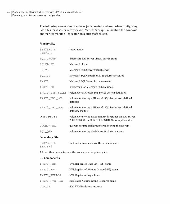
The following names describe the objects created and used when configuring two sites for disaster recovery with Veritas Storage Foundation for Windows and Veritas Volume Replicator on a Microsoft cluster.
Primary Site
SYSTEM1 & SYSTEM2
server names
SQL_GROUP Microsoft SQL Server virtual server group
SQLCLUST Microsoft cluster
SQLVS Microsoft SQL Server virtual server
SQL_IP Microsoft SQL virtual server IP address resource
INST1 Microsoft SQL Server instance name
INST1_DG disk group for Microsoft SQL volumes
INST1_SYS_FILES volume for Microsoft SQL Server system data files
INST1_DB1_VOL volume for storing a Microsoft SQL Server user-defined database
INST1_DB1_LOG volume for storing a Microsoft SQL Server user-defined database log file
INST1_DB1_FS volume for storing FILESTREAM filegroups on SQL Server 2008, 2008 R2, or 2012 (if FILESTREAM is implemented)
QUORUM_DG quorum volume disk group for mirroring the quorum
SQL_QRM volume for storing the Microsoft cluster quorum
Secondary Site
SYSTEM3 & SYSTEM4
first and second nodes of the secondary site
All the other parameters are the same as on the primary site.
DR Components
INST1_RDS VVR Replicated Data Set (RDS) name
INST1_RVG VVR Replicated Volume Group (RVG) name
INST1_REPLOG VVR Replicator log volume
INST1_RVG_RES Replicated Volume Group Resource name
VVR_IP SQL RVG IP address resource
Chapter
4Installing SFW with Microsoft clustering
This chapter covers the following topics:
■ Tasks for installing and configuring SFW with Microsoft clustering
■ Configuring the storage hardware and network
■ Establishing a Microsoft failover cluster
■ Establishing a Microsoft failover cluster
■ Installing SFW with Microsoft Failover Cluster option
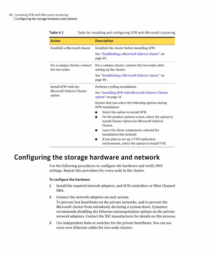
Tasks for installing and configuring SFW with Microsoft clustering
Table 4-1 shows the tasks to complete before and during Veritas Storage Foundation for Windows (SFW) installation on a Microsoft cluster.
Table 4-1 Tasks for installing and configuring SFW with Microsoft clustering
Action Description
Configure the storage hardware and network
■ Set up the storage hardware for a cluster environment,
■ Verify the DNS entries and binding order for the systems on which SQL will be installed.
See “Configuring the storage hardware and network” on page 48.
48 Installing SFW with Microsoft clusteringConfiguring the storage hardware and network
Configuring the storage hardware and networkUse the following procedures to configure the hardware and verify DNS settings. Repeat this procedure for every node in the cluster.
To configure the hardware
1 Install the required network adapters, and SCSI controllers or Fibre Channel HBA.
2 Connect the network adapters on each system.
To prevent lost heartbeats on the private networks, and to prevent the Microsoft cluster from mistakenly declaring a system down, Symantec recommends disabling the Ethernet autonegotiation options on the private network adapters. Contact the NIC manufacturer for details on this process.
3 Use independent hubs or switches for the private heartbeats. You can use cross-over Ethernet cables for two-node clusters.
Establish a Microsoft cluster Establish the cluster before installing SFW.
See “Establishing a Microsoft failover cluster” on page 49.
For a campus cluster, connect the two nodes
For a campus cluster, connect the two nodes after setting up the cluster.
See “Establishing a Microsoft failover cluster” on page 49.
Install SFW with the Microsoft Failover Cluster option
Perform a rolling installation.
See “Installing SFW with Microsoft Failover Cluster option” on page 51.
Ensure that you select the following options during SFW installation:
■ Select the option to install SFW.
■ On the product options screen, select the option to install Cluster Option for Microsoft Failover Cluster.
■ Leave the client components selected for installation (the default).
■ If you plan to set up a VVR replication environment, select the option to install VVR.
Table 4-1 Tasks for installing and configuring SFW with Microsoft clustering
Action Description

49Installing SFW with Microsoft clusteringEstablishing a Microsoft failover cluster
4 Verify that each system can access the storage devices. Verify that each system recognizes the attached shared disk and that the attached shared disks are visible.
To verify the DNS settings and binding order
1 From the Control Panel, access the Network Connections window.
2 Ensure the public network adapter is the first bound adapter:
■ From the Advanced menu, click Advanced Settings.
■ In the Adapters and Bindings tab, verify the public adapter is the first adapter in the Connections list. If necessary, use the arrow button to move the adapter to the top of the list.
3 Ensure that DNS name resolution is enabled. Make sure that you use the public network adapter, and not those configured for the private network:
■ In the Network Connections window, double-click the adapter for the public network to access its properties.
■ In the Public Status dialog box, on the General tab, click Properties.
■ In the Public Properties dialog box, on the General tab, select the Internet Protocol (TCP/IP) check box and click Properties.
■ Select the Use the following DNS server addresses option and verify the correct value for the IP address of the DNS server.
■ Click Advanced.
■ In the DNS tab, make sure the Register this connection’s address in DNS check box is selected. Make sure the correct domain suffix is entered in the DNS suffix for this connection field.
Establishing a Microsoft failover clusterYou should establish the Microsoft failover cluster before you install Veritas Storage Foundation for Windows (SFW).
Refer to the Microsoft documentation for details on establishing a failover cluster. In addition, you should be aware of the following SFW related requirement: Setting up a Microsoft failover cluster creates physical disk resources for all the basic disks on the shared bus. In the SFW environment, this means that before you create your SFW cluster disk groups, you must first remove these physical disk resources from the cluster. Otherwise, a reservation conflict occurs. After creating the SFW cluster disk groups, you will add Volume Manager Disk Group resources to the cluster, instead of physical disk resources.

50 Installing SFW with Microsoft clusteringEstablishing a Microsoft failover cluster
Note: You can install the SFW option for Microsoft Failover Cluster on a machine that is not a member of a Microsoft cluster. However, if that machine becomes the first node in a Microsoft cluster, the Volume Manager Disk Group resource type must be manually registered. For more information, see the Veritas Storage Foundation and High Availability Solutions Installation and Upgrade Guide.

51Installing SFW with Microsoft clusteringCampus cluster: Connecting the two nodes
Campus cluster: Connecting the two nodesMake the necessary connections between the two sites after you configure the Microsoft cluster. The cluster is already active on Server A, so Microsoft clustering is now in control of the cluster storage on Server A, and both nodes of the storage cannot be accessed at the same time by the operating system.
To connect the two nodes
1 Connect corresponding cables between the three network cards on the two sites.
2 Connect the two switches at the two sites through the storage interconnect.
3 Test the connectivity between the two sites. Test the IP addresses of all the network adapter cards in the cluster. Bring up the command window and type ping ipaddress, where the ipaddress is the corresponding network adapter in the other node.
Installing SFW with Microsoft Failover Cluster option
This section assumes you have already configured a Microsoft cluster and you are installing SFW on an inactive system that does not own any cluster resources.
Symantec recommends a rolling installation to install SFW. For a rolling installation, you must first install SFW on an inactive system. If your resource groups are on the system where you are installing SFW, you must move the resource groups from the SFW system to another system in the cluster.
After SFW is installed on an inactive system, move the resource groups to this system, and make the other systems inactive. Then install SFW on the other inactive systems in the Microsoft cluster simultaneously.
During SFW installation using the product installer, make the following selections:
■ Select Storage Foundation for Windows as the product to install.
■ When selecting the available options from the server components, ensure that you select the following:
■ Select the Cluster Option for Microsoft Cluster Service (MSCS)/Failover Cluster option.
■ If you are planning a disaster recovery configuration using Veritas Volume Replicator, select the Veritas Volume Replicator option.

52 Installing SFW with Microsoft clusteringInstalling SFW with Microsoft Failover Cluster option
■ Leave the client components selected (the default).
During installation, the installer will display a message box about Quorum Arbitration. The Quorum Arbitration time settings are adjusted to ensure optimal functionality of a dynamic quorum resource on a mirrored dynamic volume.
The quorum arbitration minimum and maximum time settings are used to set the limits of the time period that Microsoft clustering allows for quorum arbitration. Quorum arbitration is the process that occurs when the controlling node of the cluster is no longer active and other nodes of the cluster attempt to gain control of the quorum resource and thus control of the cluster. Refer to the Veritas Storage Foundation Administrator’s Guide for information on the settings.
For additional details on using the product installer or command line installation, see the SFW HA Solutions Installation and Upgrade Guide.

Chapter
5Configuring SFW storage
This chapter covers the following topics:
■ Tasks for configuring SFW storage
■ Planning for SFW cluster disk groups and volumes
■ Considerations when creating disk groups and volumes for a campus cluster
■ Considerations when creating volumes for a DR configuration using VVR replication
■ Viewing the available disk storage
■ Creating dynamic cluster disk groups
■ Adding disks to campus cluster sites
■ Creating dynamic volumes for high availability clusters
■ Creating dynamic volumes for campus clusters
■ Managing disk group and volumes
Tasks for configuring SFW storageYou use Veritas Storage Foundation for Windows to create dynamic cluster disk groups and volumes for a cluster environment.

54 Configuring SFW storagePlanning for SFW cluster disk groups and volumes
Table 5-1 shows the tasks for configuring disk groups and volumes.
Planning for SFW cluster disk groups and volumesA dynamic cluster disk group is a collection of one or more disks that behave as a single storage repository and which can potentially be accessed by different
Table 5-1 Tasks for configuring disk groups and volumes
Action Description
Plan the disk groups and volumes to create
See “Planning for SFW cluster disk groups and volumes” on page 54.
If you are creating a campus cluster or a disaster recovery configuration, review additional information.
See “Considerations when creating disk groups and volumes for a campus cluster” on page 60.
See “Considerations when creating volumes for a DR configuration using VVR replication” on page 61.
Configure disk groups Use the VEA console to create disk groups.
See “Creating dynamic cluster disk groups” on page 62.
Note: Setting up a Microsoft failover cluster creates physical disk resources for all the basic disks on the shared bus. To use these disks when you create your SFW cluster disk groups, you must first remove the physical disk resources from the cluster. Otherwise, a reservation conflict occurs.
For campus clusters, add disks to sites
To implement site-based allocation for volumes on campus clusters, you add the disks in the disk group to campus cluster sites.
See “Adding disks to campus cluster sites” on page 65.
Configure volumes Use the VEA console to create volumes.
See “Creating dynamic volumes for high availability clusters” on page 65.
See “Creating dynamic volumes for campus clusters” on page 69.
Understand how to deport and import disk groups and volumes to cluster nodes
When installing the application, you may need to deport and import disk groups and volumes to the different cluster nodes.
See “Managing disk group and volumes” on page 73.

55Configuring SFW storagePlanning for SFW cluster disk groups and volumes
computers. Within each disk group, you can have dynamic volumes with different layouts.
Note: You create a cluster disk group and volumes on only one node of a cluster. The volumes can be accessed by other nodes in a high-availability cluster by first deporting the cluster disk group from the current node and then importing it on the desired node. In a campus cluster, the volumes are mirrored across the storage arrays.
Before creating a disk group, consider the following:
■ The type of volume configurations that are required.
■ The number of LUNs required for the disk group.
■ The implications of backup and restore operations on the disk group setup.
■ The size of databases and logs which depend on the traffic load
■ For campus clusters, consider the following:
■ The disk groups and number of disks on each site
For campus clusters, each disk group must contain an equal number of disks on each site.
■ Each volume should be a mirrored volume with one plex of the volume on Site A’s storage array and the other plex of the volume on Site B’s storage array.
■ In a Microsoft cluster, plan to include a disk group for the mirrored quorum resource. If possible, use small disks. Microsoft recommends 500 MB for the quorum disk.
■ In a high-availability configuration, Symantec recommends using at least 3 disks for the mirrored quorum resource.
■ In a campus cluster configuration, because each site must contain an equal number of disks, Symantec recommends a 4-way mirrored quorum, 2 mirrors on each site.
See the following for additional guidelines specific to your configuration:
■ “Considerations when creating disk groups and volumes for a campus cluster” on page 60
■ “Considerations when creating volumes for a DR configuration using VVR replication” on page 61

56 Configuring SFW storagePlanning for SFW cluster disk groups and volumes
Sample high-availability cluster storage configurationThe number of disk groups for SQL Server depends on the planned organization of the data. The application program files need to be installed on the local drive of the server. Data files and other related files, such as logs, or FILESTREAM filegroups (if implemented), are placed on the shared storage in a cluster disk group.
Symantec recommends that you place database files and log files on separate volumes.
Symantec recommends that you place FILESTREAM filegroups (for SQL Server 2008, 2008 R2, or 2012) on separate volumes.
You create at least one disk group for the system data files. You may want to create additional disk groups for user databases.
Figure 5-1 shows an example configuration of the disk groups and volumes for SQL Server in a Microsoft cluster environment.
Figure 5-1 SFW disk groups and volumes for SQL virtual server SQLVS in a Microsoft high-availability cluster
SQL disk group INST1_DG contains three volumes:
■ INST1_DB1_VOL contains the SQL database. Each database typically resides on a separate volume.

57Configuring SFW storagePlanning for SFW cluster disk groups and volumes
■ INST1_DB1_LOG contains the transaction log.
■ INST1_SYS_FILES contains the volume for Microsoft SQL Server system data files.
This configuration is a simple example. The recommended practice for disk groups and volume layout is dependent on your environment.
For SQL Server 2008, 2008 R2, or 2012, if FILESTREAM is implemented, the configuration should also contain a separate volume for the FILESTREAM filegroup.
Sample campus cluster storage configurationFor the Microsoft SQL Server application data files, you could create a separate disk group for each database. Symantec recommends that you place database files, log files, and (if implemented) FILESTREAM filegroups on separate volumes.
SQL disk group INST1_DG contains three volumes:
■ INST1_DB1_VOL contains the SQL database. Each database typically resides on a separate volume.
■ INST1_DB1_LOG contains the transaction log.
■ INST1_SYS_FILES contains the volume for Microsoft SQL Server system data files.
This configuration is a simple example. The recommended practice for disk groups and volume layout is dependent on your environment.
For SQL Server 2008, 2008 R2, or 2012, if FILESTREAM is implemented, the configuration should also contain a separate volume for the FILESTREAM filegroup.
Note that in a campus cluster each disk group spans the storage arrays at both sites. The data and database log on Site A are mirrored to Site B. Each mirrored volume can have more than two disks, but must have an even number, such as four. All the application data could be in one large mirrored volume with multiple disks, but the same number of disks are required on both sites for the mirroring.
A four-way mirror for the quorum volume provides additional redundancy. The minimum configuration would be a two-way mirror. If possible, use small disks for the quorum volume. Microsoft recommends 500 MB for the quorum volume.
Figure 5-2 shows an example campus cluster storage configuration in a Microsoft cluster environment.
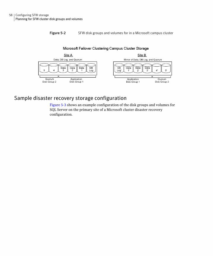
58 Configuring SFW storagePlanning for SFW cluster disk groups and volumes
Figure 5-2 SFW disk groups and volumes for in a Microsoft campus cluster
Sample disaster recovery storage configurationFigure 5-3 shows an example configuration of the disk groups and volumes for SQL Server on the primary site of a Microsoft cluster disaster recovery configuration.

59Configuring SFW storagePlanning for SFW cluster disk groups and volumes
Figure 5-3 SFW disk groups and volumes for SQL virtual server In a Microsoft disaster recover configuration
SQL disk group INST1_DG contains at least four volumes:
■ INST1_DB1_VOL contains the SQL database. Each database typically resides on a separate volume.
■ INST1_DB1_LOG contains the transaction log.
■ INST1_SYS_FILES contains the volume for Microsoft SQL Server system data files.
■ INST1_REPLOG contains the replicator log for VVR.
For SQL Server 2008, 2008 R2, or 2012, if FILESTREAM is implemented, the configuration should also contain a separate volume for the FILESTREAM filegroup.
Warning: When configuring the disk groups and volumes on the secondary site, be sure to use the same disk group and volume names as on the primary site.

60 Configuring SFW storageConsiderations when creating disk groups and volumes for a campus cluster
Considerations when creating disk groups andvolumes for a campus cluster
When you create the disk groups for a campus cluster, ensure that each disk group has the same number of disks on each physical site. You create each volume as a mirrored volume with one plex of the volume on Site A’s storage array and the other plex of the volume on Site B’s storage array.
Symantec recommends using the SFW site-aware allocation feature for campus cluster storage. Site-aware allocation can ensure that site boundary limits are maintained for operations like volume grow, subdisk move, and disk relocation.
Enabling site-aware allocation for campus clusters requires the following steps in the VEA:
■ After creating the disk groups, you tag the disks with site names to enable site-aware allocation. This is a separate operation, referred to in the VEA as adding disks to a site.
As an example, say you had a disk group with four disks. Disk1 and Disk2 are physically located on Site A. Disk3 and Disk4 are physically located on Site B. Therefore, you add Disk1 and Disk2 to “site_a” and add Disk3 and Disk4 to “site_b”.
■ During volume creation, you specify the volume site type as Site Separated. This ensures that the volume is restricted to the disks on the selected site.
Note: The hot relocation operation does not adhere to site boundary restrictions. If hot relocation causes the site boundary to be crossed, then the Site Separated property of the volumes is changed to Siteless. This is done so as not to disable hot relocation. To restore site boundaries later, you can relocate the data that crossed the site boundary back to a disk on the original site and then change back the properties of the affected volumes.
For more information on site-aware allocation, refer to the Veritas Storage Foundation Administrator’s Guide.
When you create the volumes for a campus cluster, consider the following:
■ During disk selection, configure the volume as “Site Separated” and select the two sites of the campus cluster from the site list.
■ For volume attributes, select the “mirrored” and “mirrored across enclosures” options.
■ Symantec recommends using either simple mirrored (concatenated) or striped mirrored options for the new volumes. Striped mirrored gives you better performance compared to concatenated.
61Configuring SFW storageConsiderations when creating volumes for a DR configuration using VVR replication
When selecting striped mirrored, select two columns in order to stripe one enclosure that is mirrored to the second enclosure.
■ During the volume creation procedure for Site Separated volumes, you can only create as many mirrors as there are sites. However, once volume creation is complete, you can add additional mirrors if desired.
■ Choosing “Mirrored” and the “mirrored across” option without having two enclosures that meet requirements causes new volume creation to fail.
■ You cannot selecting RAID-5 for mirroring.
■ Selecting “stripe across enclosures” is not recommended because then you need four enclosures, instead of two.
■ Logging can slow performance.
Considerations when creating volumes for aDR configuration using VVR replication
Before creating a disk group and volumes for a DR configuration using VVR replication, consider the following:
■ Replicating the system databases is not required or recommended. Make sure that the system databases are not placed on volumes that will be replicated.
■ Do not assign a drive letter to the Replicator Log volume. This will limit access to that volume and avoid potential data corruption. You can create the Replicator Log volume while using the wizard for setting up the replicated data set.
■ VVR does not support these types of volumes:
■ Storage Foundation for Windows (software) RAID 5 volumes
■ Volumes with the Dirty Region Log (DRL)
■ Volumes with a comma in their names
■ For the Replicator Log volume, in addition to the above types also make sure that the volume does not have a DCM.
Caution: Do not use volume types that are not supported by VVR.

62 Configuring SFW storageViewing the available disk storage
Viewing the available disk storageBefore creating disk groups and volumes you may want to view available disk storage.
Note: If User Access Control (UAC) is enabled on Windows Server 2008 systems, then you cannot log on to VEA GUI with an account that is not a member of the Administrators group, such as a guest user. This happens because such user does not have the "Write" permission for the "Veritas" folder in the installation directory (typically, C:\Program Files\Veritas). As a workaround, an OS administrator user can set "Write" permission for the guest user using the Security tab of the "Veritas" folder's properties.
To view the available disk storage
1 Open the VEA console by clicking Start > All Programs >Symantec> Veritas Storage Foundation >Veritas Enterprise Administrator and select a profile if prompted.
2 Click Connect to a Host or Domain.
3 In the Connect dialog box select the host name from the pull-down menu and click Connect.
To connect to the local system, select localhost. Provide the user name, password, and domain if prompted.
4 In the VEA configuration tree, expand hostname > StorageAgent and then click Disks.
The internal names for the disks which the current system can access for available storage are displayed, with names Harddisk1, Harddisk2, etc. The list includes both disks internal to the local system and any external storage that is available.
Creating dynamic cluster disk groupsYou create a dynamic cluster disk group with volumes on shared storage so that they can be shared between nodes in the cluster.
Part of the process of creating a dynamic disk group is assigning it a name. You must choose a name that is unique to your environment. Make note of this name, as it will be required later.
To create dynamic cluster disk groups, use the Veritas Enterprise Administrator (VEA). The VEA can be invoked on one of the servers and can be used to connect
63Configuring SFW storageCreating dynamic cluster disk groups
to all the other servers. However, VEA can also be launched on client system and can be used to manage all the servers remotely.
Note: Setting up a Microsoft failover cluster creates physical disk resources for all the basic disks on the shared bus. To use these disks when you create your SFW cluster disk groups, you must first remove the physical disk resources from the cluster. Otherwise, a reservation conflict occurs. After creating the SFW cluster disk groups, you will add Volume Manager Disk Group resources to the cluster, instead of physical disk resources.
Note: Dynamic disks belonging to a Microsoft Disk Management Disk Group do not support cluster disk groups.
To create a dynamic disk group
1 Open the VEA console by clicking Start > All Programs > Symantec > Veritas Storage Foundation > Veritas Enterprise Administrator (or launch the VEA from the Solutions Configuration Center) and select a profile if prompted.
2 Click Connect to a Host or Domain.
3 In the Connect dialog box, select the host name from the pull-down menu and click Connect.
To connect to the local system, select localhost. Provide the user name, password, and domain if prompted.
4 To start the New Dynamic Disk Group wizard, expand the tree view under the host node, right click the Disk Groups icon, and select New Dynamic Disk Group from the context menu.
5 In the Welcome screen of the New Dynamic Disk Group wizard, click Next.

64 Configuring SFW storageCreating dynamic cluster disk groups
6 Provide information about the cluster disk group.
■ In the Group name field, enter a name for the disk group (for example, INST1_DG).
■ Check the Create cluster group check box if you wish to create cluster dynamic disk groups that are used in a shared storage environment.
■ Select the appropriate disks in the Available disks list, and use the Add button to move them to the Selected disks list.
Optionally, check the Disk names prefix checkbox and enter a disk name prefix to give the disks in the disk group a specific identifier.
For example, entering TestGroup as the prefix for a disk group that contains three disks creates TestGroup1, TestGroup2, and TestGroup3 as internal names for the disks in the disk group.
Note: For Windows Server 2008, Windows Disk Management Compatible Dynamic Disk Group creates a type of disk group that is created by Windows Disk Management (LDM).
■ Click Next.
7 Click Next to accept the confirmation screen with the selected disks.
8 Click Finish to create the dynamic disk group.

65Configuring SFW storageAdding disks to campus cluster sites
Adding disks to campus cluster sitesFor campus cluster storage, Symantec recommends using Veritas Storage Foundation for Windows (SFW) site-aware allocation. To enable site-aware allocation, you assign a site name to disks after they are added to a disk group. In the VEA assigning a site name is referred to as adding disks to a site.
For example, Disk1 and Disk2 are physically located on Site A and Disk3 and Disk4 are physically located on Site B. Therefore, you add Disk1 and Disk2 to site_a and add Disk3 and Disk4 to site_b.
To add disks to a site
1 From the VEA console, right-click a disk that needs to be added to a site and select Add Disk to Site.
Disks must be part of a dynamic disk group in order to add them to a site.
2 In the Add Disk to a Site screen, choose one of the following:
■ Choose Select a new site and specify a new site name.
The site name can include any alphanumeric value and valid characters like the period (.), dash (-), and underscore ( _ ). It cannot exceed 31 characters. Site names are case insensitive; all names are converted to lowercase.
■ Choose Available Sites and select a site from the list.
3 From the Available Disks column, select the disk or disks to add to the specified site.
4 Click OK.
Creating dynamic volumes for high availability clusters
This section will guide you through the process of creating a volume on a dynamic disk group.
You can use this procedure for volumes in a high availability cluster. For volumes in a campus cluster, see the following:
■ “Creating dynamic volumes for campus clusters” on page 69
Before you begin, review the following topic if applicable to your environment:
■ “Considerations when creating disk groups and volumes for a campus cluster” on page 60

66 Configuring SFW storageCreating dynamic volumes for high availability clusters
Note: When assigning drive letters to volumes, ensure that the drive letters that you assign are available on all nodes.
To create dynamic volumes
1 If the VEA console is not already open, click Start > All Programs > Symantec > Veritas Storage Foundation > Veritas Enterprise Administrator and select a profile if prompted.
2 Click Connect to a Host or Domain.
3 In the Connect dialog box select the host name from the pull-down menu and click Connect.
To connect to the local system, select localhost. Provide the user name, password, and domain if prompted.
4 To start the New Volume wizard, expand the tree view under the host node to display all the disk groups. Right click a disk group and select New Volume from the context menu.
You can right-click the disk group you have just created, for example INST1_DG.
5 At the New Volume wizard opening screen, click Next.
6 Select the disks for the volume.
■ Make sure the appropriate disk group name appears in the Group name drop-down list.
■ For Site Preference, leave the setting as Siteless (the default).
■ Automatic disk selection is the default setting. To manually select the disks, click Manually select disks and use the Add and Remove buttons to move the appropriate disks to the Selected disks list. Manual selection of disks is recommended.
■ You may also check Disable Track Alignment to disable track alignment for the volume. Disabling Track Alignment means that the volume does not store blocks of data in alignment with the boundaries of the physical track of the disk.
■ Click Next.
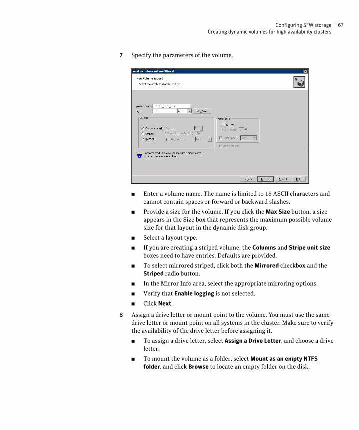
67Configuring SFW storageCreating dynamic volumes for high availability clusters
7 Specify the parameters of the volume.
■ Enter a volume name. The name is limited to 18 ASCII characters and cannot contain spaces or forward or backward slashes.
■ Provide a size for the volume. If you click the Max Size button, a size appears in the Size box that represents the maximum possible volume size for that layout in the dynamic disk group.
■ Select a layout type.
■ If you are creating a striped volume, the Columns and Stripe unit size boxes need to have entries. Defaults are provided.
■ To select mirrored striped, click both the Mirrored checkbox and the Striped radio button.
■ In the Mirror Info area, select the appropriate mirroring options.
■ Verify that Enable logging is not selected.
■ Click Next.
8 Assign a drive letter or mount point to the volume. You must use the same drive letter or mount point on all systems in the cluster. Make sure to verify the availability of the drive letter before assigning it.
■ To assign a drive letter, select Assign a Drive Letter, and choose a drive letter.
■ To mount the volume as a folder, select Mount as an empty NTFS folder, and click Browse to locate an empty folder on the disk.

68 Configuring SFW storageCreating dynamic volumes for high availability clusters
■ If creating a Replicator Log volume for Veritas Volume Replicator, select Do not assign a drive letter.
9 Click Next.
10 Create an NTFS file system.
■ Make sure the Format this volume checkbox is checked and click NTFS.
■ For a VVR configuration, for the Replicator Log volume only, clear the Format this volume check box.
■ Select an allocation size or accept the default.

69Configuring SFW storageCreating dynamic volumes for campus clusters
■ The file system label is optional. SFW makes the volume name the file system label.
■ Select Perform a quick format if you want to save time.
■ Select Enable file and folder compression to save disk space. Note that compression consumes system resources and performs encryption and decryption, which may result in reduced system performance.
Note: If you plan to use this volume to install SQL Server, do not select the Enable file and folder compression checkbox. The SQL Server installation cannot copy files on a compressed or encrypted folder.
■ Click Next.
11 Click Finish to create the new volume.
12 Repeat these steps to create additional volumes.
Create the cluster disk group and volumes on the first node of the cluster only.
Creating dynamic volumes for campus clustersThis section will guide you through the process of creating a volume on a dynamic disk group for a campus cluster.
For creating volumes for other types of clusters, see the following:
■ “Creating dynamic volumes for high availability clusters” on page 65
Before you begin, review the following topics:
■ “Considerations when creating disk groups and volumes for a campus cluster” on page 60
■ “Adding disks to campus cluster sites” on page 65
Note: When assigning drive letters to volumes, ensure that the drive letters that you assign are available on all nodes.
To create dynamic volumes
1 If the VEA console is not already open, click Start > All Programs > Symantec > Veritas Storage Foundation > Veritas Enterprise Administrator on the desktop. (Skip to step 4 if VEA is already connected to the appropriate host.)
2 Click Connect to a Host or Domain.
70 Configuring SFW storageCreating dynamic volumes for campus clusters
3 In the Connect dialog box select the host name and click Connect. To connect to the local system, select localhost. Provide the user name, password, and domain if prompted.
4 To start the New Volume wizard, expand the tree view under the host node to display all the disk groups. Right click a disk group and select New Volume from the context menu.
You can right-click the disk group you have just created, for example INST1_DG.
5 At the New Volume wizard opening screen, click Next.
6 Select the disks for the volume as follows:
Click Next.
Group name Make sure the appropriate disk group is selected.
Site preference Select the Site Separated option.
Select site from Select the campus cluster sites. Press CTRL to select multiple sites.
Note: If no sites are listed, the disks have not yet been added to a site.
Auto select disks Automatic disk selection is recommended for campus clusters. SFW automatically selects the disks based on the following criteria:
■ Their port assignment (disks with two different ports are selected). Note that in the list of available disks, the entry after each disk name starts with the port number. For example, the “P3” in the entry P3C0T2L1 refers to port 3.
■ Amount of available space on the disks. SFW will pick two disks (one from each array) with the most space.
Manually select disks If you manually select disks, use the Add and Remove buttons to move the appropriate disks to the Selected disks list.
Disable Track Alignment
You may also check Disable Track Alignment to disable track alignment for the volume. Disabling Track Alignment means that the volume does not store blocks of data in alignment with the boundaries of the physical track of the disk.

71Configuring SFW storageCreating dynamic volumes for campus clusters
7 Specify the volume attributes as follows:
Click Next.
Volume name Specify a name for the volume. The name is limited to 18 ASCII characters and cannot contain spaces or forward or backward slashes.
Size Specify a size for the volume. If you click Max Size, the Size box shows the maximum possible volume size for that layout in the dynamic disk group.
Layout Ensure that the Mirrored checkbox is selected.
Select a layout type as follows:
Select either Concatenated or Striped.
If you are creating a striped volume, the Columns and Stripe
unit size boxes need to have entries. Defaults are provided. In addition, click the Stripe across checkbox and select Ports from the drop-down list.
Mirror Info Click Mirror across and select Enclosures from the drop-down list.
When creating a site separated volume, as required for campus clusters, the number of mirrors must correspond to the number of sites. If needed, you can add more mirrors after creating the volume.
Enable logging Verify that this option is not selected.
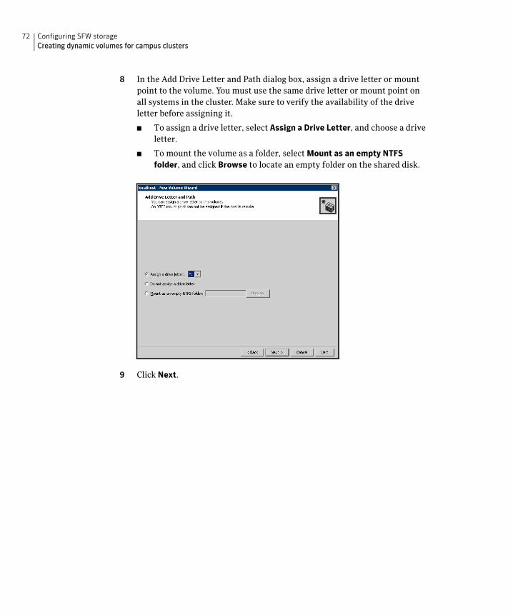
72 Configuring SFW storageCreating dynamic volumes for campus clusters
8 In the Add Drive Letter and Path dialog box, assign a drive letter or mount point to the volume. You must use the same drive letter or mount point on all systems in the cluster. Make sure to verify the availability of the drive letter before assigning it.
■ To assign a drive letter, select Assign a Drive Letter, and choose a drive letter.
■ To mount the volume as a folder, select Mount as an empty NTFS folder, and click Browse to locate an empty folder on the shared disk.
9 Click Next.

73Configuring SFW storageManaging disk group and volumes
10 Create an NTFS file system.
■ Make sure the Format this volume checkbox is checked and select NTFS.
■ Select an allocation size or accept the Default.
■ The file system label is optional. SFW makes the volume name the file system label.
■ Select Perform a quick format if you want to save time.
■ Select Enable file and folder compression to save disk space. Note that compression consumes system resources and performs encryption and decryption, which may result in reduced system performance. Click Next.
11 Click Finish to create the new volume.
12 Repeat these steps to create additional volumes as needed.
Note: Create the cluster disk group and volumes on the first node of the cluster only.
Managing disk group and volumesDuring the process of setting up an SFW environment, refer to these general procedures for managing disk groups and volumes:
■ When a disk group is initially created, it is imported on the node where it is created.

74 Configuring SFW storageManaging disk group and volumes
■ A disk group can be imported on only one node at a time.
■ To move a cluster dynamic disk group from one node to another, unmount the volumes in the disk group, deport the disk group from its current node, import it to a new node and mount the volumes.
Importing a disk group and mounting a volumeUse the VEA Console to import a disk group and mount a volume.
To import a disk group
1 From the VEA Console, right-click a disk name in a disk group or the group name in the Groups tab or tree view.
2 From the menu, click Import Dynamic Disk Group.
To mount a volume
1 If the disk group is not imported, import it.
2 To verify if a disk group is imported, from the VEA Console, click the Disks tab and check if the status is imported.
3 Right-click the volume, click File System, and click Change Drive Letter and Path.
4 Select one of the following options in the Drive Letter and Paths dialog box depending on whether you want to assign a drive letter to the volume or mount it as a folder.
■ To assign a drive letter
Select Assign a Drive Letter, and select a drive letter.
■ To mount the volume as a folder
Select Mount as an empty NTFS folder, and click Browse to locate an empty folder on the shared disk.
5 Click OK.
Unmounting a volume and deporting a disk groupUse the VEA Console to unmount a volume and deport a disk group.
To unmount a volume and deport the dynamic disk group
1 From the VEA tree view, right-click the volume, click File System, and click Change Drive Letter and Path.
2 In the Drive Letter and Paths dialog box, click Remove. Click OK to continue.
3 Click Yes to confirm.

75Configuring SFW storageManaging disk group and volumes
4 From the VEA tree view, right-click the disk group, and click Deport Dynamic Disk Group.
5 Click Yes.

76 Configuring SFW storageManaging disk group and volumes

Chapter
6Implementing a dynamic mirrored quorum resource
This chapter covers the following topics:
■ Tasks for implementing a dynamic mirrored quorum resource
■ Creating a dynamic cluster disk group and a mirrored volume for the quorum resource
■ Adding a Volume Manager Disk Group resource for the quorum
■ Changing the quorum resource to a dynamic mirrored quorum resource
Tasks for implementing a dynamic mirroredquorum resource
One of the key advantages of using SFW with Microsoft clustering is the ability to create a mirrored quorum resource that adds fault tolerance to the quorum and protects the cluster.
Table 6-1 shows the tasks for implementing the mirrored quorum resource.
Table 6-1 Tasks for configuring disk groups and volumes
Action Description
Create a dynamic cluster disk group and a mirrored volume for the quorum resource.
Create a dynamic cluster disk group and a mirrored volume for the quorum resource.
See “Creating a dynamic cluster disk group and a mirrored volume for the quorum resource” on page 78.
78 Implementing a dynamic mirrored quorum resourceCreating a dynamic cluster disk group and a mirrored volume for the quorum resource
Creating a dynamic cluster disk group and amirrored volume for the quorum resource
Use SFW to create a separate cluster disk group for the quorum disks. Microsoft recommends 500 MB for the quorum disk.
Note: If you add other volumes to this disk group, any failures related to their operation can cause disruptive failovers of the quorum volume. If a volume in the group experiences a high level of read/write activity, failovers may result from delayed access to the quorum volume by Microsoft clustering.
Symantec recommends the following configuration for the quorum disk group in order to create the mirrored quorum volume:
■ For a failover cluster, use three small disks; you need a minimum of two disks.
■ For a campus cluster, use four small disks.
Use the following guidelines when creating the mirrored volumes:
■ Select the Concatenated layout.
■ Select the Mirrored check box.
■ For a high-availability failover cluster, specify the three mirrors.
■ For a campus cluster, specify the four mirrors.
Detailed procedures are available for creating cluster disk groups and volumes.
See “Creating dynamic cluster disk groups” on page 62.
See “Adding disks to campus cluster sites” on page 65.
Add a Volume Manager Disk Group resource to the cluster
Add a Volume Manager Disk Group resource for the disk group that you created for the quorum.
See “Adding a Volume Manager Disk Group resource for the quorum” on page 79.
Change the cluster quorum resource to the dynamic mirrored quorum resource
Change the cluster quorum properties to use the Volume Manager Disk Group resource.
See “Changing the quorum resource to a dynamic mirrored quorum resource” on page 80.
Table 6-1 Tasks for configuring disk groups and volumes
Action Description

79Implementing a dynamic mirrored quorum resourceAdding a Volume Manager Disk Group resource for the quorum
Adding a Volume Manager Disk Group resourcefor the quorum
You first create a service or application for the quorum resource and name it (for example, QUORUM).
You add the Volume Manager Disk Group resource corresponding to the disk group that you created for the quorum.
To add a Volume Manager Disk Group resource for the quorum
1 If Failover Cluster Management is already open, then proceed to Step 2.
To launch Failover Cluster Management, select it from Start > Administrative Tools > Failover Cluster Management.
2 Verify that the cluster is online on the same node where you created the disk group.
3 In the left pane of Failover Cluster Management, right-click Services and Applications and select More Actions > Create Empty Service or Application.
4 Right-click the new group and rename it, for example QUORUM.
5 Right-click QUORUM and select Add a resource > More resources > Add Volume Manager Disk Group.
6 Right-click New Volume Manager Disk Group in the center pane and click Properties.
7 In the General tab of the Properties dialog box, type a name for the resource in the Resource Name field, for example, QUORUM_DG_RES.
8 On the Properties tab, in the Disk Group Name field, type the name of the disk group that you previously created for the quorum, and click OK to close the dialog box.
9 Right-click the Quorum disk group resource (for example, QUORUM_DG_RES) in the left pane and select Bring this resource online.
The specified disk group resource, QUORUM_DG_RES resource, is created under the Quorum group (for example, QUORUM).
80 Implementing a dynamic mirrored quorum resourceChanging the quorum resource to a dynamic mirrored quorum resource
Changing the quorum resource to a dynamicmirrored quorum resource
After adding a Volume Manager Disk Group resource for the quorum, you change the cluster quorum properties to use that resource. This changes the quorum resource to a dynamic mirrored quorum resource.
Use the following procedure to configure the cluster quorum settings and change the quorum resource to a dynamic mirrored quorum resource.
To change the quorum to a dynamic mirrored quorum resource
1 In Failover Cluster Management, right-click the cluster node in the configuration tree, and select More Actions > Configure Cluster Quorum Settings.
The Configure Cluster Quorum Wizard opens.
2 Review the screen and click Next.
3 Select either the Node and Disk Majority or No Majority: Disk Only radio button, and click Next.
4 Select the storage resource that you want to assign as the disk witness for the quorum and click Next.
This is the Volume Manager Disk Group resource that you previously created for the quorum disk group, for example, QUORUM_DG_RES.
5 Review the information in the Confirmation screen and click Next.
6 Click Finish to close the wizard.
Chapter
7Installing SQL Server andconfiguring resources
This chapter covers the following topics:
■ Tasks for installing and configuring SQL Server
■ Creating the resource group for the SQL Server instance
■ Prerequisites for installing SQL Server
■ Installing SQL Server
■ Dependency graph for SQL Server
■ Verifying the SQL Server group in the Microsoft cluster

82 Installing SQL Server and configuring resourcesTasks for installing and configuring SQL Server
Tasks for installing and configuring SQL ServerTable 7-1 show the process for deploying SQL Server with SFW in a Microsoft failover cluster.
Table 7-1 Process for deploying SQL Server with SFW in a Microsoft failover cluster
Action Description
Configure disk groups and volumes for SQL Server
If you have not yet done so, use the VEA console to create disk groups and volumes for SQL Server.
“Tasks for configuring SFW storage” on page 53
Create the SQL virtual server resource group
■ Create a SQL Server resource group in the cluster.
■ Add the VMDG disk group resource(s).
See “Creating the resource group for the SQL Server instance” on page 83.
Install SQL Server ■ Review the prerequisites for installationSee “Prerequisites for installing SQL Server” on page 84.
■ Mount the disk group and volumes created for the data files on the node where you install.See “Managing disk group and volumes” on page 73.
■ Install the software. Ensure that you install the data files to the path of the dynamic volume on shared storage.See “Installing SQL Server 2005 in an SFW environment” on page 85.See “Installing SQL Server 2008, 2008 R2, or 2012 in an SFW environment” on page 86.
Verify the resource dependencies
See “Dependency graph for SQL Server” on page 87.
Verify the cluster configuration
Move the online SQL Server cluster group to the second node and back to the first node.
See “Verifying the SQL Server group in the Microsoft cluster” on page 88.

83Installing SQL Server and configuring resourcesCreating the resource group for the SQL Server instance
Creating the resource group for the SQL Server instance
Before installing SQL Server you must do the following tasks:
■ Create the SQL Server resource group.
■ Add the resource for the SFW disk group that you created for SQL Server.
SQL virtual server installation requires a separate volume on which the system database files will be placed. Before installation, you create a Volume Manager Disk Group resource for the disk group that contains this volume. Creating this resource will enable SQL to monitor the system database files.
If you created additional SFW disk groups for SQL Server, for example, for user databases, you add Volume Manager Disk Group resources for those as well.
SQL Server installation adds the required SQL Server resources to the resource group and sets the appropriate dependencies for them.
Note: Before creating the resource, start the cluster service on all the nodes in the cluster.
To create the SQL Server resource group and add a disk group resource
1 Launch Failover Cluster Management (Start > Administrative Tools > Failover Cluster Management) and make sure you are connected to the required cluster.
2 In the left pane, right-click Services and Applications and select More Actions > Create Empty Service or Application. An empty group named New service or application is created. Right-click it and rename it, for example, SQL_GROUP.
3 In the left pane, right-click the SQL Server resource group you created (for example, SQL_GROUP) and select Add a resource > More resources > Add Volume Manager Disk Group.
4 In the center panel under Disk Drives, double-click New Volume Manager Disk Group to open its Properties dialog box.
5 On the General tab of the Properties dialog box, type a name for the resource.
For example, type SQL_DG_RES.
6 On the Properties tab, in the Disk Group Name field, type the exact name of the disk group you previously created for the application (for example, INST1_DG), and click OK to close the dialog box.

84 Installing SQL Server and configuring resourcesPrerequisites for installing SQL Server
7 Right-click the newly named resource and select Bring this resource online.
Prerequisites for installing SQL Server Before you begin installing SQL Server, note the following prerequisites for installing in the SFW environment:
■ Make sure that you have created the SFW disk groups and volumes for SQL Server.
See “Tasks for configuring SFW storage” on page 53.
■ Make sure that you have created the SQL Server resource group and added the resource for the SQL Server disk group.
See “Creating the resource group for the SQL Server instance” on page 83.
■ Make sure that the SFW cluster disk group for SQL Server is imported to the first node and the volumes are mounted.
See “Managing disk group and volumes” on page 73.
■ Make sure that each node has a local drive letter in common with all the other nodes in the cluster to enable installation of the binaries in exactly the same path on each cluster node.
■ If you are installing on a secondary site for a disaster recovery configuration, make sure that you take the SQL Network Name resource offline on the primary site before you begin installation on the secondary site. This will also offline the dependent resources. If the sites are on the same subnet and therefore use the same SQL IP address, ensure that the IP Address resource is offline on the primary site before beginning installation on the secondary site.
See “Creating a parallel environment on the secondary site” on page 92.
■ Ensure that the [NT AUTHORITY\SYSTEM] account is granted the sysadmin server role (from SQL Management Studio Console) on each node.

85Installing SQL Server and configuring resourcesInstalling SQL Server
Installing SQL Server Choose the appropriate procedure for your environment:
■ “Installing SQL Server 2005 in an SFW environment” on page 85
■ “Installing SQL Server 2008, 2008 R2, or 2012 in an SFW environment” on page 86
Installing SQL Server 2005 in an SFW environmentReview the prerequisites for installation before you begin.
See “Prerequisites for installing SQL Server” on page 84.
Refer to the Microsoft documentation for detailed installation information for creating a new SQL Server 2005 failover cluster. As you progress through the installation, use the following guidelines to create an installation that will function properly in a Microsoft cluster environment with SQL Server 2005 and SFW:
■ Set the installation path for the data files to the drive letter and location of the SFW volume created for the SQL Server system data files (for example, INST1_SYS_FILES). Allow the rest of the path (Program Files\Microsoft SQL Server) to remain. This must be the same path on all nodes.
The Setup program installs the system databases on the specified cluster (shared) disk. System databases must be on a clustered disk so that they can be shared between the nodes (and failed over when necessary), because these databases contain specific user login and database object information that must be the same for each node. The virtual server name will allow users access to the online node.
The Setup program automatically installs a new, separate instance of SQL Server binaries on the local disk of each server in the cluster. The binaries are installed in exactly the same path on each cluster node.
■ If you are installing multiple instances of SQL Serve, specify an instance name; only one default instance is allowed per cluster. Specify the same instance name when installing this instance on all cluster nodes.
■ You must assign a unique virtual server name, for example, SQLVS, during installation. Specify the same virtual server name when installing this SQL instance on all cluster nodes.
For a disaster recovery configuration, when installing on a secondary site, you must specify the same name for the SQL virtual server as that on the primary site.

86 Installing SQL Server and configuring resourcesInstalling SQL Server
■ When configuring the virtual server, specify the IP address for the SQL virtual server.
■ For the cluster group, specify the SQL Server resource group that you configured earlier.
See “Creating the resource group for the SQL Server instance” on page 83.
■ After installation, verify that SQL Server installed correctly according to Microsoft instructions. Check that the SQL virtual server group has the correct dependencies.
See “Dependency graph for SQL Server” on page 87.
Installing SQL Server 2008, 2008 R2, or 2012 in an SFW environmentReview the prerequisites for installation before you begin.
See “Prerequisites for installing SQL Server” on page 84.
During SQL Server 2008, 2008 R2, or 2012 installation, you install the first (active) node and additional nodes separately.
Refer to the Microsoft documentation for detailed installation information.
As you progress through the installation, use the following guidelines to create an installation that will function properly in a Microsoft cluster environment with SFW:
■ Ensure that you set the installation path for the data files to the drive letter and location of the SFW volume created for the SQL Server system data files (for example, INST1_SYS_FILES). Allow the rest of the path (Program Files\Microsoft SQL Server) to remain. This must be the same path on all nodes.
The Setup program installs the system databases on the specified cluster (shared) disk. System databases must be on a clustered disk so that they can be shared between the nodes (and failed over when necessary), because these databases contain specific user login and database object information that must be the same for each node. The virtual server name will allow users access to the online node.
■ If you are installing multiple instances, specify an instance name; only one default instance is allowed per cluster. Specify the same instance name when installing this instance on all cluster nodes.
■ You must assign a unique virtual server name, for example, SQLVS, during installation. Specify the same virtual server name when installing this SQL instance on all cluster nodes.
For a disaster recovery configuration, when installing on a secondary site, you must specify the same name for the SQL virtual server as that on the primary site.
87Installing SQL Server and configuring resourcesDependency graph for SQL Server
■ When configuring the virtual server, specify the IP address for the SQL virtual server.
■ For the cluster group, specify the SQL Server resource group that you configured earlier.
See “Creating the resource group for the SQL Server instance” on page 83.
■ After installation, verify that SQL Server installed correctly according to Microsoft instructions. Check that the SQL virtual server group has the correct dependencies.
Note: If you select the checkbox to enable FILESTREAM for file I/O streaming access, the installation creates a resource SQL Server FILESTREAM share of type File Share. It is created with the appropriate dependencies set on the Volume Manager Disk Group, SQL Server, and SQL Server Network Name resource.
See “Dependency graph for SQL Server” on page 87.
■ After installation on the first node of a high-availability cluster, keep the SQL virtual server group online on the active node. Unmount the volumes in the disk group, deport the disk group from its current node, import it to a new node and mount the volumes.
See “Managing disk group and volumes” on page 73.
■ Using the same guidelines, install SQL Server 2008, 2008 R2, or 2012 on additional passive nodes. Make sure that you install the binaries on the same local drive on each node.
Dependency graph for SQL ServerOnce SQL is installed, the SQL Server Resource with dependencies on the SQL Network Name and the Volume Manager Disk Group resource is created.
Figure 7-1 indicates the dependencies that are established.
Note: If you enabled the FILESTREAM file I/O streaming functionality during SQL Server 2008, 2008 R2, or 2012 installation, a FILESTREAM resource is created with a dependency on the SQL Network Name resource, the SQL Server resource, and the Volume Manager Disk Group Resource.

88 Installing SQL Server and configuring resourcesVerifying the SQL Server group in the Microsoft cluster
Figure 7-1 Dependency graph after the SQL installation is completed
Verifying the SQL Server group in the Microsoft cluster
You can verify your installation by moving the cluster between nodes to see if it fails over properly. The ultimate test of the cluster’s failover capability involves shutting down the node that is currently online and bringing it back up after the cluster fails over to the other node.
Refer to the Microsoft documentation for instructions.
Other SQL Resources
SQL Server Resource
SQL Network Name Resource “Volume Manager Disk Group” Resource
SQL Virtual IP Resource

Chapter
8Configuring disaster recovery for SQL Server in a Microsoft cluster
This chapter covers the following topics:
■ Tasks for configuring the secondary site for disaster recovery
■ Verifying the primary site configuration
■ Creating a parallel environment on the secondary site
■ VVR components overview
■ Setting up security for VVR
■ Creating resources for VVR
■ Configuring VVR: Setting up an RDS
■ Creating the RVG resource
■ Setting the SQL server resource dependency on the RVG resource
■ Working with the solution: Normal operations and recovery procedures

90 Configuring disaster recovery for SQL Server in a Microsoft clusterTasks for configuring the secondary site for disaster recovery
Tasks for configuring the secondary site for disaster recovery
After creating a high-availability Microsoft cluster with SFW and SQL Server on a primary site, you can configure a secondary site for disaster recovery.
This disaster recovery solution requires Veritas Volume Replicator (VVR).
Refer to the Veritas Volume Replicator Administrator’s Guide for additional details on VVR.
Table 8-1 describes the process for configuring the secondary site for disaster recovery.
Table 8-1 Process for configuring the secondary site for disaster recovery
Action Description
Verify the primary site configuration.
See “Verifying the primary site configuration” on page 92.
Review the prerequisites and planning information
Verify the prerequisites on the secondary site.
See “Requirements for deploying SQL Server with SFW in a Microsoft cluster” on page 30.
Note: If the DR site is on a different network segment, ensure that you allocate two IP addresses for the virtual server, one for the primary site and one for the DR site.
Understand the DR configuration.
See “Planning your disaster recovery configuration” on page 43.
Create the parallel configuration on the secondary site
Ensure that you follow the secondary site requirements and guidelines for IP addresses, disk groups and volumes, the SQL Server resource group, and SQL Server installation.
See “Creating a parallel environment on the secondary site” on page 92.
Understand the VVR components
See “VVR components overview” on page 93.
Set up security for VVR Set up the security for VVR on all nodes on both the primary and secondary sites.
See “Setting up security for VVR” on page 94.

91Configuring disaster recovery for SQL Server in a Microsoft clusterTasks for configuring the secondary site for disaster recovery
Create the cluster resources for VVR
■ Create an IP address for the Replicated Volume Group (RVG).
■ Create a Network Name resource for the Replicated Volume Group (RVG).
See “Creating resources for VVR” on page 96.
Set up an RDS Create a replicated data set (RDS) using the VVR wizard.
See “Configuring VVR: Setting up an RDS” on page 98.
Create the RVG resource (primary and secondary sites)
Create the RVG resource on both primary and secondary sites.
See “Creating the RVG resource” on page 110.
Set up the SQL Server resource dependencies
Change the SQL Server resource dependency properties so that it depends on the RVG resource instead of the Volume Manager Disk Group resource.
See “Setting the SQL server resource dependency on the RVG resource” on page 111.
Table 8-1 Process for configuring the secondary site for disaster recovery
Action Description

92 Configuring disaster recovery for SQL Server in a Microsoft clusterVerifying the primary site configuration
Verifying the primary site configurationBefore you can configure the secondary site, you set up the primary site for high availability.
See “Workflow for a high availability (HA) configuration” on page 18.
Ensure that you install the Veritas Volume Replicator option on the primary site. Ensure that you are using static IP addresses as required for VVR.
Creating a parallel environment on the secondary site
After setting up a SFW environment with Microsoft clustering on the primary site, complete the same tasks on the secondary site prior to the SQL installation.
See “Workflow for a high availability (HA) configuration” on page 18.
However, note the following guidelines and exceptions.
■ If the DR site is on a different network segment, ensure that you allocate two IP addresses for the virtual server, one for the primary site and one for the DR site.
■ During SFW installation, be sure to select the option to install VVR. (This must also be installed on the primary site.)
■ During the creation of disk groups and volumes for the secondary site, make sure the following is exactly the same as the cluster on the primary site:
■ Cluster disk group name
■ Volume names and sizes
■ Drive letters
■ Specify the same name for the SQL Server resource group as the name on the primary site.
■ Before starting the SQL installation make sure you take the SQL Server Network Name resource offline on the primary site. This will also offline the dependent SQL resources. In addition, if the secondary is in the same subnet, take the IP Address resource offline on the primary site.
■ During installation, specify the same name for the SQL virtual server as the name on the primary site.
Do not begin VVR configuration until you have completed all the steps for setting up the parallel configuration on the secondary site, including:
■ SFW installed on all nodes
■ Disk groups and volumes configured

93Configuring disaster recovery for SQL Server in a Microsoft clusterVVR components overview
■ SQL Server installed on all the nodes
VVR components overviewYou configure the following Veritas Volume Replicator components:
Replicated Volume Group (RVG)
An RVG is made up of one or more volumes in a SFW disk group. The updates made on the RVG on the primary host are sent to a configured secondary host. Thus, on the secondary host there is a corresponding RVG with a disk group of the same name and volumes with the same names. The data volumes should be the same size. Optionally, to add more redundancy, you can have multiple secondary hosts, all with the same corresponding copy of the RVG.
An RVG within a disk group is the container for replication, so if you have multiple disk groups, you will need to create a separate RVG for each disk group. It is possible to have more than one RVG in a disk group; however, the RVG cannot span across disk groups.
Replicated Data Set (RDS)
An RVG on the primary host and any corresponding RVGs on the secondary host or hosts make up a Replicated Data Set (RDS).
Replicator Log volume
Each RVG must have a Replicator Log associated with it. The Replicator Log volume at the primary site holds a copy of any RVG updates that are sent to the secondary site. The Replicator Log on the secondary site is held in reserve so that it can be used if the primary site becomes nonfunctional and the secondary site needs to become the new primary site. The log volumes at the two sites must have the same name. Symantec recommends having Replicator Log volumes of the same size at the primary site and the secondary site.

94 Configuring disaster recovery for SQL Server in a Microsoft clusterSetting up security for VVR
Setting up security for VVRAs the first configuration step for VVR replication, you must configure the VVR Security Service (VxSAS) on all cluster nodes on both the primary and secondary sites. This procedure should not be done until you have installed SFW on all cluster systems. Otherwise, you will get an error message from the VxSAS wizard if you try to select a system without SFW installed.
You can run the VxSAS wizard from any site once SFW is installed on all cluster systems; at that time, you can run the wizard for both the primary and secondary site systems. The Microsoft cluster groups can be either online or offline.
Complete the following procedure to configure the VxSAS service for VVR.
The procedure has these prerequisites:
■ You must be logged on with administrative privileges on the server for the wizard to be launched.
■ The account you specify must have administrative and log-on as service privileges on all the specified hosts.
■ Avoid specifying blank passwords. In a Windows Server environment, accounts with blank passwords are not supported for log-on service privileges.
■ Make sure that the hosts on which you want to configure the VxSAS service are accessible from the local host.
Note: For details on this required service, see Veritas Storage Foundation Veritas Volume Replicator Administrator’s Guide.
To configure the VxSAS service
1 Launch the VVR Security Service Configuration Wizard.
Click Start > All Programs > Symantec > Veritas Storage Foundation > Configuration Wizards > VVR Security Service Configuration Wizard.
or
Type vxsascfg.exe at the command prompt.
2 Read the information provided on the Welcome page and click Next.
3 Complete the Account Information panel as follows and then click Next:
Account name (domain\account)
Enter the administrative account name.
Password Specify a password.
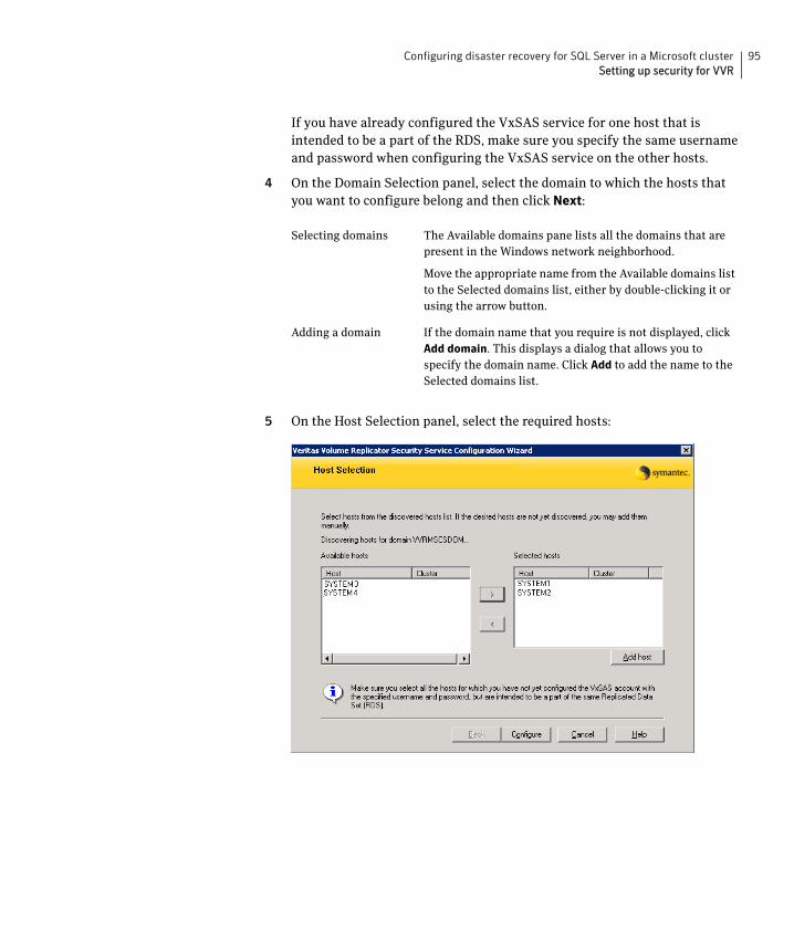
95Configuring disaster recovery for SQL Server in a Microsoft clusterSetting up security for VVR
If you have already configured the VxSAS service for one host that is intended to be a part of the RDS, make sure you specify the same username and password when configuring the VxSAS service on the other hosts.
4 On the Domain Selection panel, select the domain to which the hosts that you want to configure belong and then click Next:
5 On the Host Selection panel, select the required hosts:
Selecting domains The Available domains pane lists all the domains that are present in the Windows network neighborhood.
Move the appropriate name from the Available domains list to the Selected domains list, either by double-clicking it or using the arrow button.
Adding a domain If the domain name that you require is not displayed, click Add domain. This displays a dialog that allows you to specify the domain name. Click Add to add the name to the Selected domains list.
96 Configuring disaster recovery for SQL Server in a Microsoft clusterCreating resources for VVR
After you have selected a host name, the Configure button is enabled. Click Configure to proceed with configuring the VxSAS service.
6 After the configuration completes, the Configuration Results page displays whether or not the operation was successful. If the operation was not successful, the page displays the details on why the account update failed, along with the possible reasons for failure and recommendations on getting over the failure.
When configuring the VxSAS service for VVR in a firewall setup, the VxSAS wizard may not be able to configure the machines that are across the firewall, although the Host Selection dialog may list these nodes. In this case, configure the VxSAS service locally on the machines that are across the firewall.
Click Back to change any information you had provided earlier.
7 Click Finish to exit the wizard.
Creating resources for VVRCreate the resources for VVR replication at the primary and secondary sites using the Failover Cluster Management tool. You create a network name resource and IP address resource to be used for VVR replication.
A separate valid IP address is necessary for VVR replication, because on the secondary cluster before a disaster, the application IP must be offline whereas the VVR IP must be online.
You create the resources for the primary site and then repeat the procedure to create the resources on the secondary site.
Selecting hosts The Available hosts pane lists the hosts that are present in the specified domain.
Move the appropriate host from the Available hosts list to the Selected hosts list, either by double-clicking it or using the arrow button. Use the Shift key with the up or down arrow keys to select multiple hosts.
Adding a host If the host name you require is not displayed, click Add
host. In the Add Host dialog specify the required host name or IP in the Host Name field. Click Add to add the name to the Selected hosts list.

97Configuring disaster recovery for SQL Server in a Microsoft clusterCreating resources for VVR
To create a Network Name resource and IP address resource for VVR replication
1 Right-click on the application group and select Add a Resource > Client Access Point.
2 In the Client Access Point panel of the New Resource Wizard, specify the following:
■ In the Name field, specify a name for the Network Name resource. The default is the name of the group you selected. Specify any name except the node and the virtual server name. The network name you assign when creating the resource for the secondary site must be different from the network name for the primary site.
■ Select the network and specify the IP address.
Click Next.
3 In the Confirmation panel, review the information and click Next.
4 When configuration is complete, click Finish.
5 Repeat the same procedure to create the IP and the Network Name resource at the secondary site.
6 Bring the resources online.

98 Configuring disaster recovery for SQL Server in a Microsoft clusterConfiguring VVR: Setting up an RDS
Configuring VVR: Setting up an RDSFor each disk group you created for the application, you set up a Replicated Data Set (RDS) on the primary and secondary hosts. The Setup Replicated Data Set Wizard enables you to configure an RDS for both sites.
Before running the wizard, verify the following:
■ Verify that the disk groups and volumes for the SQL user database files and log files have been created. The Replicator Log volume can be created while running the wizard if not created earlier.
■ Verify that VxSAS has been configured.
■ Verify that the SQL virtual server Network Name resource resource is offline on the secondary site. This would also bring offline all the dependent SQL resources. If on the same subnet, ensure that the SQL IP Address resource is also offline.
■ Verify that you have set the appropriate IP preference, whether VVR should use IPv4 or IPv6 addresses, before configuring replication. The default setting is IPv4.
When you specify host names while configuring replication, VVR resolves the host names with the IP addresses associated with them. This setting determines which IP protocol VVR uses to resolve the host names.
Use Veritas Enterprise Administrator (VEA) (Control Panel > VVR Configuration > IP Settings tab) to set the IP preference.
VVR does not support these types of volumes:
■ Storage Foundation for Windows (software) RAID 5 volumes
■ Volumes with the Dirty Region Log (DRL)
■ Volumes with a comma in their names
■ For the Replicator Log volume, in addition to the above types also make sure that the volume does not have a DCM.
Caution: Do not use volume types that are not supported by VVR.
The following procedure enables you to set up an RDS on the primary and secondary sites and to start replication.
To create the Replicated Data Set
1 Use the Veritas Enterprise Administrator (VEA) console to launch the Setup Replicated Data Set Wizard from the cluster node on the Primary where the cluster disk group is imported:
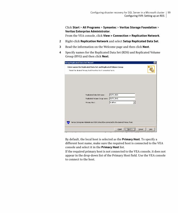
99Configuring disaster recovery for SQL Server in a Microsoft clusterConfiguring VVR: Setting up an RDS
Click Start > All Programs > Symantec > Veritas Storage Foundation > Veritas Enterprise Administrator.
From the VEA console, click View > Connection > Replication Network.
2 Right-click Replication Network and select Setup Replicated Data Set.
3 Read the information on the Welcome page and then click Next.
4 Specify names for the Replicated Data Set (RDS) and Replicated Volume Group (RVG) and then click Next.
By default, the local host is selected as the Primary Host. To specify a different host name, make sure the required host is connected to the VEA console and select it in the Primary Host list.
If the required primary host is not connected to the VEA console, it does not appear in the drop-down list of the Primary Host field. Use the VEA console to connect to the host.

100 Configuring disaster recovery for SQL Server in a Microsoft clusterConfiguring VVR: Setting up an RDS
5 Select from the table the dynamic disk group and data volumes that will undergo replication and then click Next.
To select multiple volumes, press the Shift or Control key while using the up or down arrow keys.
By default, a mirrored DCM log is automatically added for all selected volumes. If disk space is inadequate to create a DCM log with two plexes, a single plex is created.

101Configuring disaster recovery for SQL Server in a Microsoft clusterConfiguring VVR: Setting up an RDS
6 Complete the Select or create a volume for Replicator Log page as follows:
To select an existing volume
■ Select the volume for the Replicator Log in the table (INST1_REPLOG).
If the volume does not appear in the table, click Back and verify that the Replicator Log volume was not selected on the previous page.
■ Click Next.
To create a new volume
■ Click Create Volume and enter the following information in the dialog box that displays.
Name Enter the name for the volume in the Name field.
Size Enter a size for the volume in the Size field.
Layout Select the desired volume layout.

102 Configuring disaster recovery for SQL Server in a Microsoft clusterConfiguring VVR: Setting up an RDS
■ Click OK to create the Replicator Log volume.
■ Click Next in the Select or create a volume for Replicator Log dialog box.
7 Review the information on the summary page and click Create Primary RVG.
8 After the Primary RVG has been created successfully, VVR displays the following message:RDS with Primary RVG has been created successfully. Do you want to add Secondary host to this RDS for replication now?
Click No to exit the Setup Replicated Data Set wizard without adding the Secondary host. To add the Secondary host later, use the Add Secondary option from the RDS right-click menu.
Click Yes to add the Secondary host to the Primary RDS now. The Specify Secondary host for replication page appears.
9 On the Specify Secondary host for replication page, enter the name or IP address of the Secondary host in the Secondary Host field and then click Next.
If the Secondary host is not connected to VEA, the wizard tries to connect it when you click Next. This wizard allows you to specify only one Secondary host. Additional Secondary hosts can be added using the Add Secondary option from the RDS right-click menu.
Disk Selection Enables you to specify the disk selection method.
■ Enable the Thin Provisioned Disks Only check box to ensure that the Replicator Log volume is created only on Thin Provisioned (TP) disks.
Note: The check box will remain disabled if the diskgroup does not have any TP disk.
If this option is selected along with the Select disks
automatically option, then the Replicator Log volume will be created only on TP disks. However, if you enable this check box along with Select disks manually option, then the user can select only TP disks from Available Disks.
For more information on Thin Provisioning refer to the Veritas Storage Foundation Administrator’s Guide.
■ Choose the Select disks automatically option if you want VVR to select the disks.
■ Choose the Select disks manually option to use specific disks from the Available disks pane for creating the volume. Either double-click on it or select Add to move the disks into the Selected disks pane.

103Configuring disaster recovery for SQL Server in a Microsoft clusterConfiguring VVR: Setting up an RDS
Wait till the connection process is complete and then click Next again.
10 If only a disk group without any data volumes or Replicator Log, as on the Primary host exists on the Secondary, then VVR displays a message. Read the message carefully.
The option to automatically create volumes on the Secondary host is available only if the disks that are part of the disk group have:
■ The same or larger amount of space as that on the Primary
■ Enough space to create volumes with the same layout as on the Primary
Otherwise, the RDS setup wizard enables you to create the required volumes manually.
■ Click Yes to automatically create the Secondary data volumes and the Replicator Log.
■ Click No to create the Secondary data volumes and the Replicator Log manually, using the Volume Information on the connected hosts page.
11 The Volume Information on connected hosts page appears. This page displays information on the availability of volumes on the Secondary nodes, if the Primary and Secondary hosts are connected to VEA.
This page does not appear if all the required volumes that are available on the Primary host are also available on the Secondary hosts.
■ If the required data volumes and the Replicator Log have not been created on the Secondary host, then the page displays the appropriate message against the volume name on the Secondary.
■ If an error occurs or a volume needs to be created, a volume displays with a red icon and a description of the situation. To address the error, or to create a new Replicator Log volume on the secondary site, click the volume on the secondary site, click the available task button and follow the wizard.
Depending on the discrepancies between the volumes on the primary site and the secondary site, you may have to create a new volume, recreate or resize a volume (change attributes), or remove either a DRL or DCM log.
When all the replicated volumes meet the replication requirements and display a green check mark, click Next.
■ If all the data volumes to be replicated meet the requirements, this screen does not occur.
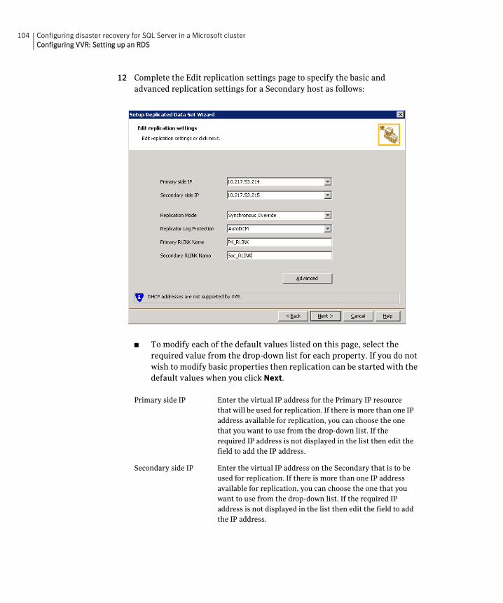
104 Configuring disaster recovery for SQL Server in a Microsoft clusterConfiguring VVR: Setting up an RDS
12 Complete the Edit replication settings page to specify the basic and advanced replication settings for a Secondary host as follows:
■ To modify each of the default values listed on this page, select the required value from the drop-down list for each property. If you do not wish to modify basic properties then replication can be started with the default values when you click Next.
Primary side IP Enter the virtual IP address for the Primary IP resource that will be used for replication. If there is more than one IP address available for replication, you can choose the one that you want to use from the drop-down list. If the required IP address is not displayed in the list then edit the field to add the IP address.
Secondary side IP Enter the virtual IP address on the Secondary that is to be used for replication. If there is more than one IP address available for replication, you can choose the one that you want to use from the drop-down list. If the required IP address is not displayed in the list then edit the field to add the IP address.

105Configuring disaster recovery for SQL Server in a Microsoft clusterConfiguring VVR: Setting up an RDS
Replication Mode Select the required mode of replication: Synchronous
Override, Synchronous, or Asynchronous. The default is synchronous override.
Synchronous Override enables synchronous updates under typical operating conditions. If the Secondary site is disconnected from the Primary site, and write operations occur on the Primary site, the mode of replication temporarily switches to Asynchronous.
Synchronous determines updates from the application on the Primary site are completed only after the Secondary site successfully receives the updates.
Asynchronous determines updates from the application on the Primary site are completed after VVR updates in the Replicator Log. From there, VVR writes the data to the data volume and replicates the updates to the secondary site asynchronously.
If the Secondary is set to the synchronous mode of replication and is disconnected, the Primary data volumes with NTFS file systems may be displayed with the status as MISSING.
Replicator Log Protection
The AutoDCM is the default selected mode for the Replicator Log overflow protection when all the volumes in the Primary RVG have a DCM log. The DCM is enabled when the Replicator Log overflows.
The DCM option enables the Replicator Log protection for the Secondary host when the Replicator Log overflows, and the connection between the Primary and Secondary is lost. This option is available only if all the data volumes under the Primary RVG have a DCM Log associated with them.
The Off option disables Replicator Log Overflow protection.
In the case of the Bunker node. Replicator Log protection is set to Off, by default. Thus, if the Primary RLINK overflows due to the Bunker RLINK, then this RLINK is detached.

106 Configuring disaster recovery for SQL Server in a Microsoft clusterConfiguring VVR: Setting up an RDS
The Override option enables log protection. If the Secondary node is still connected and the Replicator Log is about to overflow then the writes are stalled until a predetermined amount of space, that is, 5% or 20 MB (whichever is lesser) becomes available in the Replicator Log.
If the Secondary becomes inactive due to disconnection or administrative action then Replicator Log protection is disabled, and the Replicator Log overflows.
The Fail option enables log protection. If the log is about to overflow the writes are stalled until a predetermined amount of space, that is, 5% or 20 MB (whichever is lesser) becomes available in the Replicator Log. If the connection between Primary and Secondary RVG is broken, then, any new writes to the Primary RVG are failed.
Primary RLINK Name This option enables you to specify a Primary RLINK name of your choice. If you do not specify any name then VVR assigns a default name.
Secondary RLINK Name This option enables you to specify a Secondary RLINK name of your choice. If you do not specify any name then VVR assigns a default name.

107Configuring disaster recovery for SQL Server in a Microsoft clusterConfiguring VVR: Setting up an RDS
■ If you want to specify advanced replication settings, click Advanced. Edit the replication settings for a secondary host as needed.
Latency protection Determines the extent of stalling write operations on the primary site to allow the secondary site to “catch up” with the updates before new write operations can occur.
Off is the default option and disables latency protection.
Fail enables latency protection. If the number of outstanding write operations reaches the High Mark Value (described below), and the secondary site is connected, VVR stalls the subsequent write operations until the number of outstanding write operations is lowered to the Low Mark Value (described below). If the secondary site is disconnected, the subsequent write operations fail.
Override enables latency protection. This option resembles the Off option when the secondary site is disconnected, and the Fail option when the secondary site is connected.
Throttling of write operations affects application performance on the primary site; use this protection only when necessary according to replication throughput and application write patterns.
High Mark Value Is enabled only when either the Override or Fail latency protection option is selected. This value triggers the stalling of write operations and specifies the maximum number of pending updates on the Replicator Log waiting for replication to the secondary site. The default value is 10000, the maximum number of updates allowed in a Replicator Log.
108 Configuring disaster recovery for SQL Server in a Microsoft clusterConfiguring VVR: Setting up an RDS
Click OK to close the dialog box and then click Next.
13 On the Start Replication page, choose the appropriate option as follows:
Low Mark Value Is enabled only when either the Override or Fail latency protection options is selected. After reaching the High Mark Value, write operations on the Replicator Log are stalled until the number of pending updates drops to an acceptable point at which the secondary site can “catch up” to the activity on the primary site; this acceptable point is determined by the Low Mark Value. The default value is 9950.
Caution: When determining the high mark and low mark values for latency protection, select a range that is sufficient but not too large to prevent long durations of throttling for write operations.
Protocol UDP/IP is the default protocol for replication.
Packet Size Updates to the host on the secondary site are sent in packets; the default size 1400 bytes. The option to select the packet size is enabled only when UDP/IP protocol is selected.
Bandwidth By default, VVR uses the maximum available bandwidth. To control the bandwidth used, specify the bandwidth limit in Mbps.
Enable Compression Enable this checkbox if you want to enable Compression for the secondary host.

109Configuring disaster recovery for SQL Server in a Microsoft clusterConfiguring VVR: Setting up an RDS
■ To add the Secondary and start replication immediately, select Start Replication with one of the following options:
■ To add the secondary without starting replication, deselect the Start Replication option. You can start replication later by using the Start Replication option from the Secondary RVG right-click menu.
■ Click Next to display the Summary page.
14 Review the information.
Click Back to change any information you had specified and click Finish to add the secondary host to the RDS and exit the wizard.
Synchronize Automatically
If virtual IPs have been created, select the Synchronize
Automatically option, which is the default recommended for initial setup to start synchronization of Secondary and start replication immediately.
If the virtual IPs for replication are not yet created, automatic synchronization remains paused and resumes after the Replication Service Group is created and brought online.
When this option is selected, VVR by default performs intelligent synchronization to replicate only those blocks on a volume that are being used by the file system. If required, you can disable intelligent synchronization.
Note: Intelligent synchronization is applicable only to volumes with the NTFS file systems and not to raw volumes or volumes with FAT/FAT32 file systems.
Synchronize from Checkpoint
If you want to use this method, then you must first create a checkpoint.
If you have considerable amount of data on the Primary data volumes, then you may first want to synchronize the secondary for existing data using the backup-restore method with checkpoint. After the restore is complete, use the Synchronize from Checkpoint option to start replication from checkpoint to synchronize the secondary with the writes that happened when backup-restore was in progress.
For information on synchronizing from checkpoints, refer Veritas Storage Foundation TM Volume Replicator Administrator's Guide.

110 Configuring disaster recovery for SQL Server in a Microsoft clusterCreating the RVG resource
Creating the RVG resource To enable a disaster recovery setup, once VVR is configured you will need to create the Replicated Volume Group (RVG) resource on the primary and secondary sites.
You add the RVG resource to the SQL Server resource group. You configure the RVG resource to depend on the VVR IP resource and on the appropriate Volume Manager Disk Group resource.
Since an RVG cannot span disk groups, if you have more than one disk group configured for the application, create a separate RVG resource for each disk group.
To create a Replicated Volume Group (RVG) resource
1 In Failover Cluster Management, expand Services and Applications, right-click the SQL Server virtual server group that you have created and select Add a resource > More resources > Add Replicated Volume Group.
The New Replicated Volume Group appears in the center panel under Disk Drives.
2 Right-click New Replicated Volume Group and click Properties.
3 On the General tab of the Properties dialog box, in the Resource Name field, type a name for the RVG resource.
4 On the Dependencies tab, add the dependencies for the RVG resource:
■ Click the box Click here to add a dependency
■ From the Resource drop-down list, select the network name you created for the RVG. Click Insert.
■ Click the box Click here to add a dependency
■ From the Resource drop-down list, select the Volume Manager Disk Group resource created for the application disk group. Click Insert.
5 On the Properties tab, specify the following:
■ In the rvgName field, type the same name that you assigned the RVG on the General tab.
■ In the dgName field, type the name assigned in the VEA to the application disk group.
6 Click OK to close the Properties dialog box.
7 Right-click the RVG resource and click Bring this resource online.
8 Repeat the same steps to create the RVG resource at the secondary site.
111Configuring disaster recovery for SQL Server in a Microsoft clusterSetting the SQL server resource dependency on the RVG resource
Setting the SQL server resource dependency on the RVG resource
The SQL Server resource was earlier set to depend on a Volume Manager Disk Group resource that corresponded to the disk group created for the application. After you add the RVG resource for that disk group, you must change the dependency. You set the database resource to depend on the RVG resource instead.
You must set the dependency on the RVG resource on both primary and secondary sites.
Note: For SQL Server 2008, 2008 R2, or 2012, your configuration may include a Filestream volume as part of the RVG. If so, you must modify the Filestream resource to remove the Volume Manager Disk Group resource from its dependency list and add the RVG resource to its dependency list. Since the SQL Server resource is also a dependency of the Filestream resource, you do not need to modify the SQL Server resource as well.
To change the SQL Server resource dependency properties
1 Ensure that the SQL Server resource is offline.
2 Right-click the SQL Server resource and select Properties.
3 On the Properties dialog box, select the Dependencies tab.
4 Make the appropriate selections on the Dependencies tab to:
■ Add the Replicated Volume Group resource to the dependencies.
■ Delete the Volume Manager Disk Group resource from the dependencies.
5 The cluster configuration is now complete. Online the entire SQL_GROUP group on the primary cluster.
Figure 8-1 indicates the dependencies required.

112 Configuring disaster recovery for SQL Server in a Microsoft clusterSetting the SQL server resource dependency on the RVG resource
Figure 8-1 Dependency graph for SQL Server
Other SQL Resources
SQL Server Resource
SQL Network Name Resource
Volume Manager Disk Group Resource SQL Virtual IP Resource
RVG Resource
VVR Virtual Name Resource
VVR Virtual IP Resource
113Configuring disaster recovery for SQL Server in a Microsoft clusterWorking with the solution: Normal operations and recovery procedures
Working with the solution: Normal operationsand recovery procedures
This section gives considerations for normal VVR operations and also describes the recovery process.
Monitoring the status of the replicationUnder normal operating conditions you can monitor the status of the replication using:
■ VEA GUI
■ Command Line Interface (CLI)
■ Performance Monitor (perfmon)
■ Alerts
For details, refer to the “Monitoring Replication” Chapter in the Veritas Volume Replicator Administrator’s Guide.
Performing planned migrationYou may want to migrate the application to the Secondary host for maintenance purposes and for testing the readiness of the Secondary host. You may need to perform a generic set of tasks as explained below.
To migrate the application to the Secondary
1 Detach the user database. See the Microsoft documentation for instructions.
Note that the master, model, and tempdb, databases cannot be detached.
2 Bring the RVG resource offline on both clusters.
3 Transfer the Primary role to the secondary using the Migrate option:
■ From the VEA screen, right-click the Primary RVG and select Migrate.
■ Select the Secondary host and click OK. The replication role is migrated to the Secondary host.
4 Assign drive letters to the volumes on the new Primary. Ensure that these drive letters are the same as that of the original Primary.
5 Bring the RVG resource online on both the clusters.
6 Bring the SQL_GROUP group online on the new Primary.
7 Attach the databases. See the Microsoft documentation for instructions.

114 Configuring disaster recovery for SQL Server in a Microsoft clusterWorking with the solution: Normal operations and recovery procedures
You can now verify that SQL runs fine on the new Primary with the replicated data. After verifying, you can revert back the roles to its original state using the same set of tasks described above.
Any changes that you make to the data on the new Primary will get replicated to the original Primary, which is now the Secondary.
Replication recovery proceduresThis section provides information on bringing up an SQL server on the Secondary host, in the event of a disaster. It also explains how to migrate the Primary role back to the original Primary host once it is in a good state after a disaster.
Bringing up SQL on the secondary host
To recover the SQL data
1 From the left-pane in the VEA GUI console on the Secondary host, right-click on the desired secondary RVG node inside the replication network.
2 Select Takeover and follow the instructions in the wizard to perform the takeover operation. You can choose to perform takeover with the following options:
■ Perform the Takeover with fast-failback option to restore the original Primary easily once it becomes available again. When performing Takeover with fast-failback, make sure that you do not select the Synchronize Automatically option.
■ Perform the Takeover without fast-failback option. In this case, you need to perform a complete synchronization of the original Primary with the new Primary. This may take quite a while depending on the size of the data volume. Only after the synchronization is complete can you migrate the Primary role back to the original Primary.
After takeover, the existing Secondary becomes the new Primary.
3 Assign drive letters to the volumes on the new Primary. Ensure that these drive letters are the same as that of the original Primary.
4 Bring the SQL_GROUP group online.
5 Attach the databases. See the Microsoft SQL Server documentation for instructions.
Now you can start using SQL on the new Primary.

115Configuring disaster recovery for SQL Server in a Microsoft clusterWorking with the solution: Normal operations and recovery procedures
Restoring the primary hostAfter a disaster, if the original Primary becomes available again you may want to revert the role of the Primary back to this host.
To restore the Primary role to the original Primary host
1 Detach the user database. See the Microsoft documentation for instructions.
Note that the master, model, and tempdb, databases cannot be detached.
2 Take the RVG resource offline on both the clusters.
3 Depending on whether you performed Takeover with or without fast-failback option, do one of the following:
■ For Takeover with the Fast-failback option, the original Primary, after it has recovered, will be in the Acting as Secondary state. If the original Primary is not in the Acting as Secondary state, verify whether your network connection has been restored.
To synchronize this original Primary and the new Primary, use the Resynchronize Secondaries option from the right-click menu of the new Primary.
■ For Takeover without the Fast-failback option, after you have performed this operation, you must convert the original Primary to a Secondary using the Make Secondary option.
Note: Before performing the Make Secondary operation, the original Primary’s RVG and the new Primary’s RVG will be shown in separate RDSs. However, after this operation they will be merged under a single RDS.
After the Make Secondary operation, the original Primary will be converted to a secondary. Right-click this secondary RVG and select Start Replication with Synchronize Automatically option.
4 After the sychronization is complete, perform a migrate operation to transfer the Primary role back to the original Primary. To do this, right-click the Primary RVG and select Migrate from the menu.
5 Ensure that the volumes have retained the same drive letters that existed before the disaster.
6 Bring the RVG resource online on the Secondary.
7 Bring the SQL_GROUP group online on the original Primary.
8 Attach the databases on the original Primary. See the Microsoft documentation for instructions.

116 Configuring disaster recovery for SQL Server in a Microsoft clusterWorking with the solution: Normal operations and recovery procedures

Index
Ccampus cluster
connecting the nodes 51disk groups 60overview 13sample configuration 57volumes 60Vxclus 43workflow 20
Ddependencies for SQL Server 87disaster recovery
overview 14sample configuration 58volumes for VVR 61workflow 23
disk group resourceadding for quorum 79adding for SQL Server 83
disk groupscampus cluster 60disaster recovery 58high availability 56planning 54quorum 78
disk space requirements 33disks, adding to campus cluster sites 65DNS settings 48
Ffailover verification 88
Hhigh availability
overview 12sample configuration 56workflow 18
Iinstallation
prerequisites for SQL Server installation 84SFW installation on cluster 51
Mmirrored volume for quorum 78
Nnetwork settings 48
Qquorum
adding resource for disk group 79arbitration settings 52changing to dynamic mirrored quorum
resource 79cluster ownership concepts 42concepts 42device configuration 36disk group 78implementing dynamic mirrored 77volume 78
Rreplicated data set 98replication
creating a Replicated Volume Group (RVG) resource 110
setting up RDS 98requirements
disk space 33SFW installation 34SQL Server installation 84system 33
resourceadding for quorum 79dependencies for SQL Server 87quorum 77

118
RVG 110SQL Server resource group 83
resource group for SQL Server 83, 87rolling installation 51
Ssample configurations
campus cluster 57disaster recovery 45, 58high availability 34, 56
security for VVR 94SFW
installing on Microsoft cluster 51sites, adding disks to 65SQL Server
creating resource group for Microsoft cluster 83
installation prerequisites 84resource dependencies 87verifying the cluster 88
storage hardware 48system requirements 33
VVolume Manager Disk Group resource
adding for quorum 79adding for SQL Server 83
volumescampus cluster 60considerations for VVR 61creating 65creating for campus clusters 69disaster recovery 56, 58planning 54quorum 78SQL Server 2008 56
VVRcreating RVG resource 110setting up RDS 98volumes 61VxSAS service 94
Vxclus utility 43VxSAS service 94