ventilation principles and designing for natural ventilation · low ventilation rates commensurate...
TRANSCRIPT
iiiiii !!!!!!! iiiiii iiiiii ::m=
;;; ..
en ..
('
(
l_.,,
Code of practice for
Ventilation principles and designing for natural ventilation
Principes de ventilation et conception des systemes de ventilation naturelle - Code de bonne pratique
Natdrllche Be!Uftung von Wohn- und BO.rogeb4.uden
NO COPYING WITHOUT BSI PERMISSION EXCEPT AS PERMITTED BY COPYRIGHT LAW
BS 5925 : 1991
AIVC #13035
• ==:: ��----.,. ........... .

BS 5925 : 1991
This British Standard, having been prepared under ihe direction of the Basic Data and Performance Criteria for Civil Engineering and Building Structures Standards Policy Committee, was published under the authority of the Standards Board and comes into effect o n 31May1991
© BSI 1991
First published September 1980 Second edition May 1991
The following BSI references relate to the work on this standard: Committee reference BDB/2 Draft for comment 89 /17211 DC
ISBN 0 580 19285 7
Committees responsible for this British Standard
The preparation of this British Standard was entrusted by the Basic Data and Performance Criteria for Civil Engineering and Building Structures Standards Policy Committee (BOB/-) to Tuchnical Committee BDB/2, upon which the following bodies were represented:
Aggregate Concrete Block Association Association for the Conservation of Energy Association of Building Component Manufacturers Association of County Councils Association of District Councils Association of Metropolitan Authorities Autoclaved Aerated Concrete Products Association Brick Development Association British Board of Agrement British Cement Association British Gas pie British Preca.st Concrete Federation Ltd. Building Employers' Confecleration Building Services Research and Information Association Chartered Institute of Building Chartered Institution of Building Services Engineers Concrete Society Consumer Policy Committee of BSI Cranfield Institute of Tuchnology Department of Education and Science Department of Energy (Energy Efficiency Office) Department of Health Department of the Environment (Building Research Establishment) Department of the Environment (Construction Industries Directorate) Department of the Environment for Northern Ireland Electricity Supply Industry in United Kingdom Eurisol (UK Mint�ral Wool Association) Flat Glass Manufacturers' Association Gypsum Products DevelopmPnt Assodation Hevac Association Institution of Civil Engineers Institution of Gas Engineers Institution of Structural Engineers Lighting Industry Jo'ederation Ltd.
Ministry of Defence Naliunal House-building Council National Illumination Committee of Great Britain
oyal lnsmute ofllnUsh'JU'Ctiifleiii<fo---------------------------------Royal Institution of Chartered Surveyors Scottish Development Department Society of Chief Architects of Local Authorities Timber Research and Development Association Trades Union Congress Watt Committee on Energy Ltd.
The following bodies were also represented in the drafting of the standard, through subcommittees and panels:
.. • • • � JI!!' ... � _.. • • ! -"· ... .. ----- __ ... - ''----�- _.._ _____ _ 1"\.�ClU.LIUll UJ. �119lLWt!lgJIL L\.fSMit:l)ilt.t J."10.JlUJ.d\.:LUJClOJ British Coal Corporation British Concrete Masonry Association Flat Roofing Contractors Advisory Board Institution of Mechanical Engineers
Medical Research Council National Council of Building Material Producers Phenolic Foam l'danufacturers' Association
Amendments issued since publication
Amd. No. Date Tuxt affected
r
(
iiiiiiiiii !!!!!! iiiiiiiiii iiiiiiiiii iiiiiiiiii !!!!!!
* C/l *
• ===�=---..,,,, ........ .
STANDARDS
Amendment No. 1 published and effective from 15 December 1995 to BS 5925 : 1991
"
Code of practice for ventilation principles and designing for natural ventilation
Correction
Clause 9. Flow characteristics of openings
Delete equation (2) and substitute the following I
Q = Cdfl.(26.p/ p) 2 (2) AMD 893M>ecember 1995
AMD 8930
- - - - - - - - - - - - - - - - - - - - - - - - - - - - - -.- �· - - - - - - - - - - - - - _r� - - - -
' ·
9612 Product code 00628060 B/540/2

(
iiiii -;;;;;;;; iiiii iiiii !!!!!
* Ul *
BS 5925 : 1991
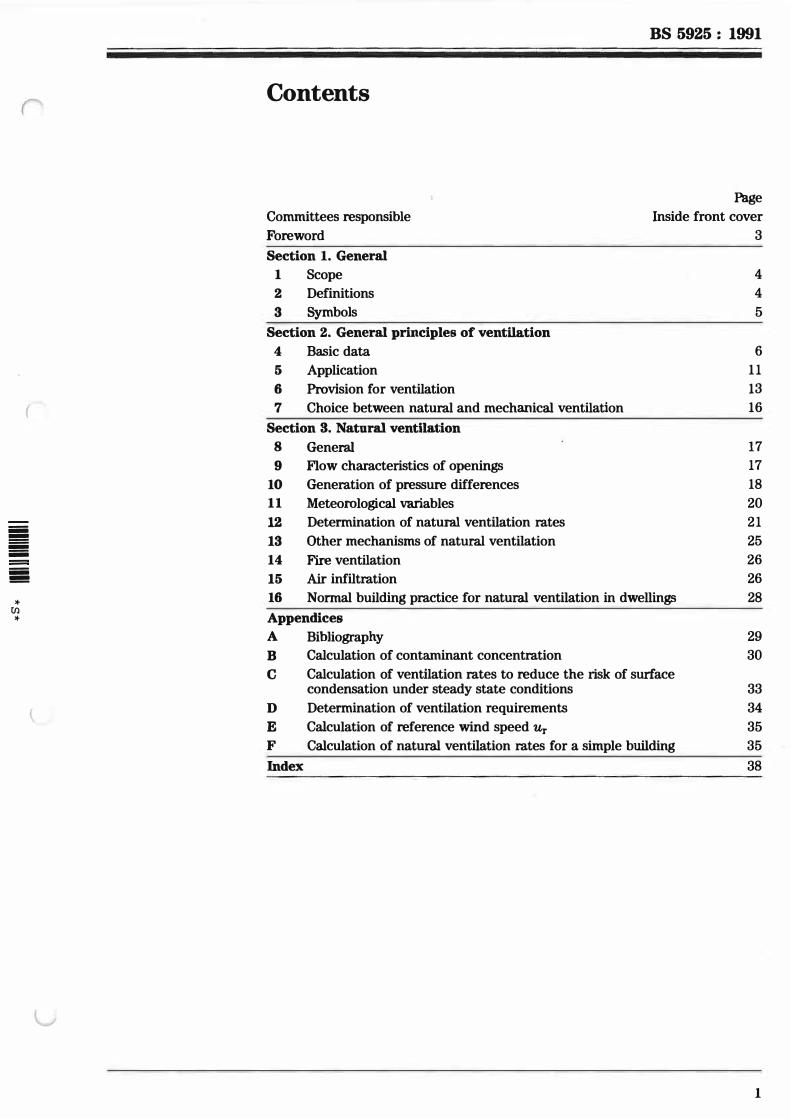
Contents
Committees responsible
Foreword
Page
Inside front cover
3
Section 1. General 1 Scope
2
3
Definitions
Symbols
Section 2. General principles of ventilation 4 Basic data
5 Application
6 Provision for ventilation
7 Choice between natural and mechanical ventilation
Section S. Natural ventilation 8 General
9 Flow characteristics of openings
10 Generation of pressure differences
11 Meteorological variables
12 Determination of natural ventilation rates
13 Other mechanisms of natural ventilation
14 Fire ventilation
15 Air infiltration
16 Normal building practice for natural ventilation in dwellin�
Appendices A Bibliography
B c
Calculation of contaminant concentration
Calculation of ventilation rates to reduce the risk of surface condensation under steady state conditions
D Determination of ventilation requirements
E Calculation of reference wind speed Ur F Calculation of natural ventilation rates for a simple building
Index
4
4
5
6
11
13
16
17
17
18
20
21
25
26
26
28
29
30
33
34
35
35
38
1
BS 5925 : 1991
2
Page
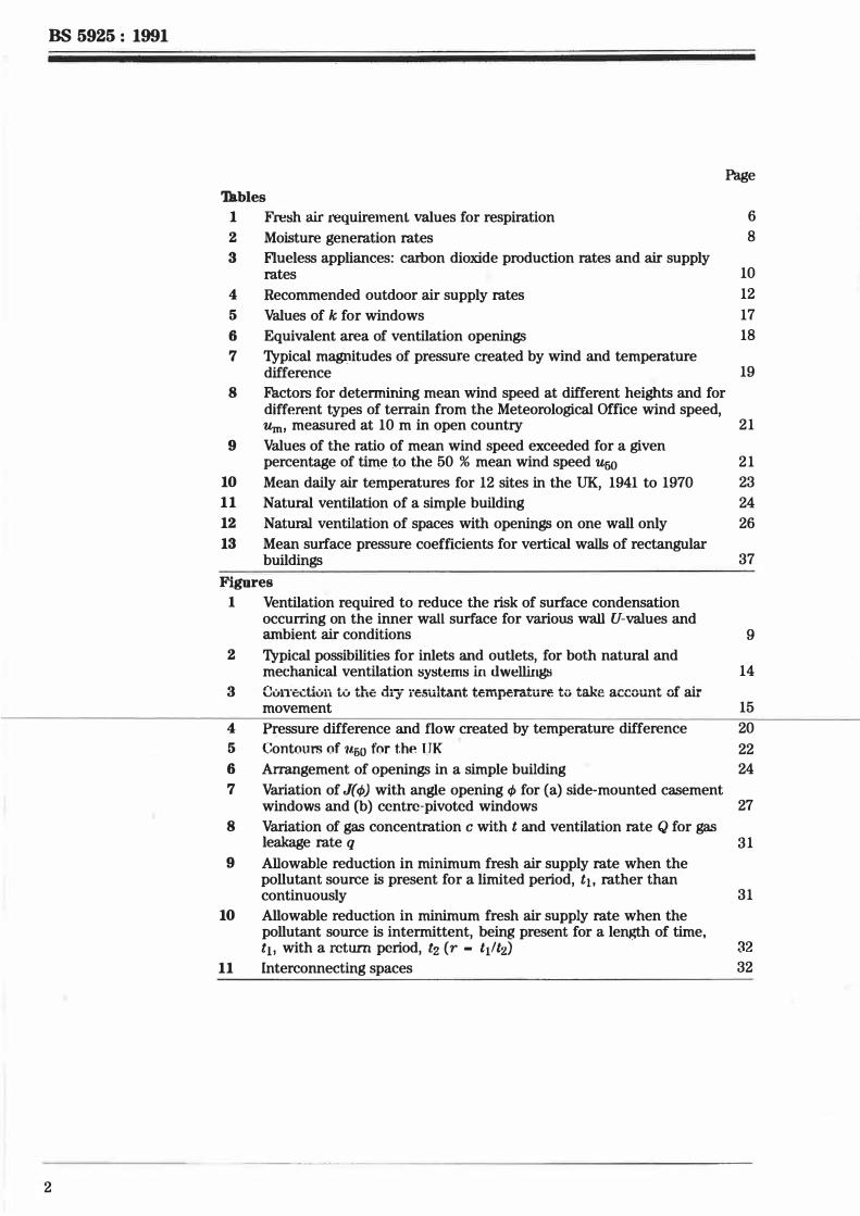
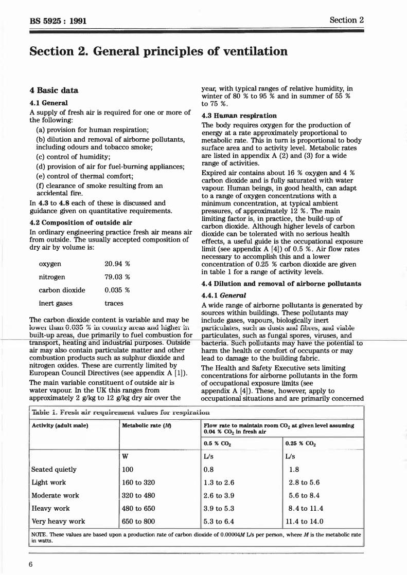
'lkbles 1 Fresh air requirement values for respiration
2 Moisture generation rates
3 Flueless appliances: carbon dioxide production rates and air supply rates
4 Recommended outdoor air supply rates
6
8
10
12
5 Values of k for windows 17
6 Equivalent area of ventilation openings 18
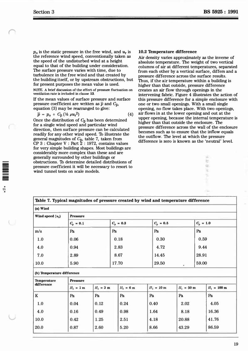
7 Typical magnitudes of pressure created by wind and temperature difference 19
8 Factors for determining mean wind speed at different heights and for different types of terrain from the Meteorological Office wind speed, Um, measured at 10 m in open country 21
9 Values of the ratio of mean wind speed exceeded for a given percentage of time to the 50 % mean wind speed u50 21
10 Mean daily air temperatures for 12 sites in the UK, 1941 to 1970 23
11 Natural ventilation of a simple building 24
12 Natural ventilation of spaces with openings on one wall only 26
13 Mean surface pressure coefficients for vertical walls of rectangular buildings 37
Figures 1 Ventilation required to reduce the risk of surface condensation
occurring on the inner wall surface for various wall U-values and ambient air conditions 9
2 Typical possibilities for inlets and outlets, for both natural and mechanical ventilation systems in dwellings 14
3 Cumt::�tiun to the dry resultant temperature to take account of air movement 15
4 Pressure difference and flow created by temperature difference 20 5 Contours of U.50 for the TTK 22 6 Arrangement of openings in a simple building 24
7 Variation of J(<P) with angle opening <P for (a) side-mounted casement windows and {b) centre-pivoted windows 27
8 Variation of gas concentration c with t and ventilation rate Q for gas leakage rate q 31
9 Allowable reduction in minimum fresh air supply rate when the pollutant source is present for a limited period, ti, rather than continuously 31
10 Allowable reduction in minimum fresh air supply rate when the pollutant source is intermittent, being present for a length of time, t11 with a return period, t2 (r - t1lti) 32
11 Interconnecting spaces 32
r
(
iiiii !!!!! iiiii iiiii iiiii !!!!!
* Ul *
BS 5925 : 1991
Foreword
This British Standard has been prepared under the direction of the Basic Data and Performance Criteria for Civil Engineering and Building Structures Standards Policy Committee. It supersedes BS 5925 : 1980, which is withdrawn.
This revision takes into account research on ventilation and indoor air quality that has taken place since the publication of BS 5925 : 1980. In particular, under section 2, the ventilation requirements for the dilution and removal of airborne pollutants have been updated and account taken of the guidance given in BS 5250. Under section 3, a new clause dealing with air infiltration has been introduced.
Recent increased awareness of the need for efficient use of energy in the design and management of buildings, as recommended in BS 8207, has led to greater insulation levels and reduced ventilation rates in both new and existing buildings. However, it is es8ential that a balance is struck between the needs for low ventilation rates commensurate with saving energy and the needs for higher ventilation rates required to ensure good indoor air quality and to reduce the risk of mould growth. Ventilation rates in different parts of a building may differ, depending on both the levels of occupancy and the occupant's activities in those parts. It is important to remember the complex interrelationship of factors affecting condensation and to take particular care when designing new buildings or considering changes or attempting to remedy problems in existing buildings.
Compliance with a British Standard does not of itself confer immunity-from legal obligations.
3
BS 5925 : 1991
Section 1. General
1 Scope This British Standard gives recommendations on the principles which should be observed when designing for the natural ventilation of buildings for human occupation. The standard is in three sections, as follows:
Section 1. General
Section 2 outlines the rnain reasons for the provision of ventilation and, where possible, recommends quantitative air flow rates. It is shown that these form the basis for air supply recommendations for different types of buildings and rooms characterized by usage. The basis for the choice between natural and mechanical ventilation is given. The design of mechanical ventilation systems is dealt with in BS 5720.
Section 3 gives recommendations on the design of natural ventilation systems and on the estimation of air infiltration rates in housing.
Appendix A is a bibliography and reference to publications listed in it are shown as: (see appendix A [15]).
Appendix B gives recommendations on evaluating contamination risks. Appendix C gives recommendations on calculating ventilation rates to reduce the risk of surface condensation under steady state conditions.
Appendix D gives recommendations on tiati:arminlnff unntil"ltinn rnrn1iranHJ1nt" ............. .., ....................... .a .. o ............. .., ...... _.., .. ..,, .... ......... �"'"-...... "''"" ................. ...,.
Section 1
2 Definitions For the purposes of this British Standard the definitions given in BS 5643 and BS 6100 apply, together with the following.
2.1 absolute temperature Tumperature measured with respect to absolute zero.
2. 2 discharge coefficient Coefficient which relates the volume flow rate through an orifice to its area and the applied pressure difference.
2.3 equivalent area Area of a sharp-edged orifice through which air would pass at the same volume flow rate, under an identical applied pressure difference, as the opening under consideration.
2.4 input rating Heat available for liberation by combustion within an appliance, based upon the gross calorific value of the fuel.
2. 5 kerosine Petroleum oil fuel suitable for appliances with small vaporizing and atomizing burners; classified as class C in BS 2869.
2.6 open-flued appliance Appliance designed to be connected to an open f1110 ''""tam• It" f'nm hu"tinn �fr h.i>in!T rh"<lum frnm ........ _ .......... J ................ , ......... .._.""'_0.0.&I_._..., ............. --- ........... -...--0 ---T� ..... -� ....... -••
Appendix E gives recommendations on !he room or internal space within which it is
calculating reference wind speed. mstali,.. Appendix F wves recununemlatiuns on calculating natural ventilation rates for a simple building.
This standard does not attempt to address thermal comfort aspects of ventilation such as indoor air movement, temperature stratification, exact position of ventilation openings etc. NarE. The titles of the nublications referred to in this standard are listed on the inside hack cover.
4
2. 7 premium �rade kerosine Kerosine suitable for flueless space heaters, complying with the requirements of the specification for class Cl petroleum oil fuels in BS 2869. NCYI'E. The non-preferred term is paraffin.
2.8 reference static pressure Static pressure in the free wind, away from any interference with the flow.
2.9 static pressure Pressure which would be recorded by a pressure gauge moving with the flow, i.e. static relative to the fluid.
2.lO wake Region of disturbed flow which persists some distance downstream of a building or similar structure exposed to the wind.
Section 1 BS 5925 : 1991
('
3 Symbols p Surface pressure
For the purposes of this British Standard the p Mean surface pressure following notation applies. Commonly used abbreviations for units of measurement are not Po Static pressure in undisturbed wind listed.
Q Volume flow rate of air A Equivalent area of an opening � Volume flow rate of air due to the A11 A2 effect of temperature only
A3, A4 Equivalent area of specific openings Qw Volume flow rate of air due to the
effect of wind only Ab
denoted in the text
Ql Reduced air flow rate for Aw intermittent contaminant emission
a Exponent relating wind speed to q Input volume flow rate of height contaminant
Cd Discharge coefficient for an opening R Ventilation rate
Gp Surface pressure coefficient r Return period of an intermittent
Gp Mean surface pressure coefficient pollutant source
t Time c Concentration of contaminant in air
iiiiii by volume u Thermal transmittance !!!!!!! iiiiii Ce Concentration of contaminant in u Wind speed iiiiii - outside air iiiiii Uin Wind speed at 10 m, exceeded for a !!!!!!!
Co Concentration of contaminant at given proportion of time * timet""O Ul Ur Reference wind speed * CE Equilibrium value of contaminant
v Room volume concentration
g Acceleration due to gravity w Width of building
H1 Vertical distance between the centres z Height
of two openings in a wall a Angle made by wind relative to
H2 Vertical distance between top and building
bottom edges of a rectangular A Difference between two values of opening in a wall
the same quantity, e.g. ACp h Vertical distance between ground
Area ratio and the eaves or parapet f
J Function relating ventilation rate (} Absolute temperature
through an open window to the Oe Absolute temperature of outside air angle of opening, <P
K Factor relating wind speed to height (Ji Absolute temperature of inside air lJ Average of inside and outside air
k Window leakage factor temperatures
L Length of a crack p Air density
l Length of a building "' Angle made by an open window with
M Metabolic rate the plane containing the wall of a building.
n Exponent relating flow rate through crack to applied pressure difference
5
BS 5925 : 1991 Section 2
Section 2. General principles of ventilation
4 Basic data
4.1 General A supply of fresh air is required for one or more of the following:
(a) provision for human respiration;
(b) dilution and removal of airborne pollutants, including odours and tobacco smoke;
(c) control of humidity;
(d) provision of air for fuel-burning appliances;
(e) control of thermal comfort;
(0 clearance of smoke resulting from an accidental fire.
In 4.3 to 4.8 each of these is discussed and guidance given on quantitative requirements.
4.2 Composition of outside air In ordinary engineering practice fresh air means air from outside. The usually accepted composition of dry air by volume is:
oxygen
nitrogen
carbon dioxide
inert gases
20.94 % 79.03 % 0.035 % traces
The carbon dioxide content is variable and may be luwe1 tlii:i.u G.G3G ?� iu l:uuut1y i:l.lt:<L'> c:U.1u higl:u::r t:1 built-up areas, due primarily to fuel combustion for transport, heating and mdustriaI purposes. Outs1ae air may also contain particulate matter and other combustion products such as sulphur dioxide and nitrogen oxides. These are currently limited by European Council Directives (see appendix A [1] ) . The main variable constituent o f outside air is water vapour. In the UK this ranges from approximately 2 g/kg to 12 g/kg dry air over the
year, with typical ranges of relative humidity, in winter of 80 % to 95 % and in summer of 55 % to 75 %. 4.3 Human respiration The body requires oxygen for the production of energy at a rate approximately proportional to metabolic rate. This in tum is proportional to body surface area and to activity level. Metabolic rates are listed in appendix A (2) and (3) for a wide range of activities.
Expired air contains about 16 % oxygen and 4 % carbon dioxide and is fully saturated with water vapour. Human beings, in good health, can adapt to a range of oxygen concentrations with a minimum concentration, at typical ambient pressures, of approximately 12 % . The main limiting factor is, in practice, the build-up of carbon dioxide. Although higher levels of carbon dioxide can be tolerated with no serious health effects, a useful guide is the occupational exposure limit (see appendix A f 4] ) of 0.5 %. Air flow rates necessary to accomplish this and a lower concentration of 0.25 % carbon dioxide are given in table 1 for a range of activity levels.
4.4 Dilution and removal of airborne pollutants
4.4. l Geneml
A wide range of airborne pollutants is generated by sources within buildings. These pollutants may include gases, vapours, biologically inert pari.il:ulaLe:s, :sul:h a:s uu:sl.:s emu fiL1e:s, ii.nu viii.bl� particulates, such as fungal spores, viruses, and
acteria. Such pollutants may have the potential to harm the health or comfort of occupants or may lead to damage to the building fabric .
The Health and Safety Executive sets limiting concentrations for airborne pollutants in the form of occupational exposure limits (see appendix A [4] ). These, however, apply to occupational situations and are primarily concerned
Tu.hie i. Fcesi1 u.ic cequ..icemeni. value� fur .tei'lph·atiuii Activity (adult male) Metabolic rate (M) Flow rate to maint.aln room C02 at given level assuming
0.04 % C02 in fresh air
0.6 % C02 0.26 % C02 ·--
w Us Us
Seated quietly 100 0.8 1.8
Light work 160 to 320 1.3 to 2.6 2.8 to 5.6
Moderate work 320 to 480 2.6 to 3.9 5.6 to 8.4
Heavy work 480 to 650 3.9 to 5.3 8.4 to 11.4
Very heavy work 650 to 800 5.3 to 6.4 11.4 to 14.0
NCJI'E. These values are based upon a production rate of carbon dioxide of 0.00004M Us per person, where Mill the metabolic rate in watts.
6
iiiiii !!!!!! iiiiii iiiiii iiiiii !!!!!!
* [/) *
Section 2
with healthy adult workers. They cannot, therefore, necessarily be applied to buildings in which the occupants may include other groups, such as children, the elderly or those in poor health. At present, there is no consistent approach to setting acceptable indoor concentrations of pollutants in such circumstances . The factors which detemtine the concentration of an indoor air pollutant are set out and discussed in appendix B. These lead to the following methods of control:
(a) source removal; (b) source control; (c) extract ventilation close to source; ( d) removal from air by filtration etc.; ( e) dilution ventilation.
Choice of method of control depends upon a number of factors, including the nature of the pollutant and its sources, capital and running costs and practicability. Ventilation will affect the concentration of any pollutant and is the most appropriate means of control where both the production rate and the limiting concentration of pollutant are well defined and where no other method can be as readily used. In practice production rates are best known where the source is combustion or where the pollutant results from the presence or activities of occupants. Production rates are less well defined where the source is related to the fabric or furnishings of the building.
4.4.2 Odour
The human olfactory system is sensitive to a wide range of airborne substances. The characteristics of odour, such as intensity and quality, and its acceptability, cannot be measured directly by instrumentation and have to be assessed by psycho-physical methods using human judgement. Occupants of buildings are rarely exposed to individual odorants but to complex mixtures, characterized by their source, the most common being body odour, tobacco odour, cooking odours and toilet odour. Control of body odour has formed the basis of standards for fresh air supply in many types of buildings for many years. Based upon the most recent research (see appendix A (5, 6 and 7]) the minimum requirement to restrict annoyance to persons entering the space from outside is 8 Lis per person, where the occupants are sedentary.
4.4.3 1bbacco smoke
'lbbacco smoke consists of 'main-stream' smoke, inhaled by the smoker, and the remainder which is termed 'side-stream' smoke. Environmental tobacco smoke consists primarily of the latter, augmented by the proportion of main-stream smoke which is exhaled by the smoker. It is a complex mixture of particles, gases and organic
BS 5925 : 1991
vapours, varying with the type of tobacco and mode of smoking. The possible effects of exposure to environmental tobacco smoke include:
(a) odour annoyance; (b) irritation of the mucous membranes in the respiratory tract and especially the eyes; (c) increased susceptibility to respiratory infection and reduced lung function; ( d) toxic reaction to certain components; and (e) increased risk of lung cancer.
The dominant criteria when assessing the required control of tobacco smoke are odour (based upon the response of non-smokers entering a space in which smoking may occur) and the level of respirable, suspended particulates (based upon standards set for particulates in the ambient air (see 4.2)). These criteria indicate that the dilution air requirement is 120 m3 per cigarette smoked. A lower air supply rate, 30 m3 to 60 m3 per cigarette smoked, should obviate mucous membrane irritation. Rate of smoking varies with individuals and circumstances but as a guide the average rate of smoking is approximately 1. 3 cigarettes per h per smoker. This figure, together with an estimate that approximately one-third of the adult population are regular smokers, yields on the basis of odour considerations a value varying between approximately 15 Lis per person in a large space in which the proportion of smokers is typical of the population at large to 40 Us per person in a space in which all occupants are assumed to be smokers.
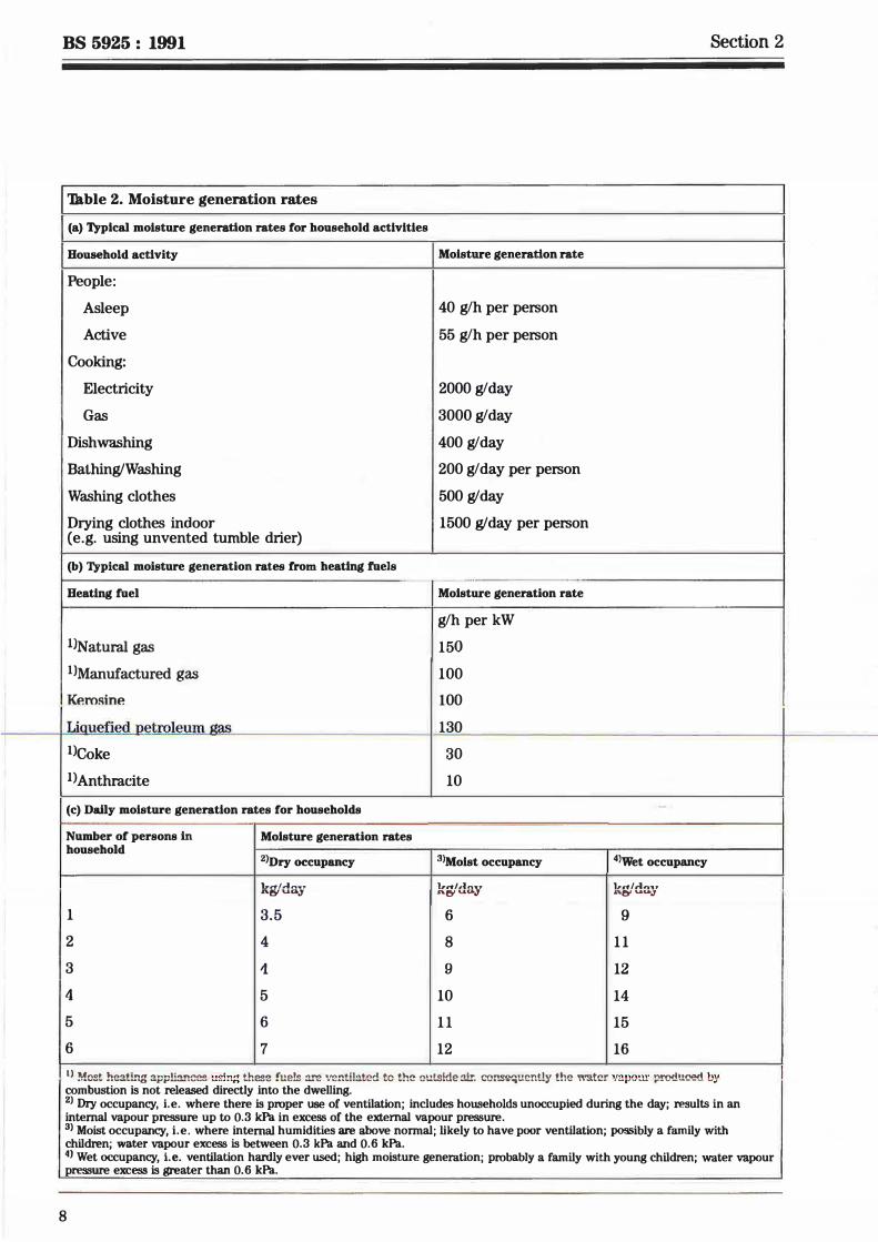
4.5 Control of internal humidity The relative humidity of air is equal to the ratio of the moisture content of the air to the moisture content of saturated air at the same temperature. Low relative humidities can give rise to respiratory discomfort and nuisance from electrostatic effects. High relative humidities incur the risk of condensation and mould growth on surfaces that have temperatures that fall below the dewpoint temperature of the air. Reference should be made to BS 5250 which deals with factors affecting condensation and mould growth in dwellings, including the thermal properties of the structure, the temperature and humidity of the outside air and the heat and moisture input. The contribution made by ventilation is to lower the moisture content of the internal air by dilution with outside air which normally has a lower moisture content. For any required moisture level the flow rate will depend upon the moisture level in the outside air, and the rate of moisture input from such sources as respiration, cooking, washing and flueless combustion of certain fuels. Thbles 2(a), 2(b) and 2(c) give some guidance on the likely moisture input rates and, given the temperature and relative
7
BS 5925 : 1991 Section 2
'lkble 2. Moisture generation rates
(a) Typical moisture generation rates for household activities
Household activity Moisture generation rate
People:
Asleep 40 g/h per person
Active 55 g/h per person
Cooking:
Electricity 2000 g/day
Gas 3000 g/day
Dish washing 400 g/day
Bathing/Washing 200 g/day per person
Washing clothes 500 g/day
Drying clothes indoor 1500 g/day per person (e.g. using unvented tumble drier)
(b) Typical moisture generation rates from heating fuels -·
Heating fuel Moisture generation rate
g/h per kW
1JNatural gas 150
1>Manufactured gas 100
KP.msine 100
Liauefied netroleum aJ:lJ:1 130
l)Coke 30
I) Anthracite 10
(c) Dally moisture generation rates for households -
Number of persons In Moisture generation rates household
2>Dry occupancy 3lMoist occupancy 4>wet occupancy
'L-d/,.I,,, • .,. h·n/,1.,,..,.. l,,n/-'l'll,.,. n.e;r U.O.J .R.Of u.ta-3 AO' '-.&UtJ
1 3.5 6 9
2 4 8 11
3 1 9 12
4 5 10 14
5 6 11 15
6 7 12 16
IJ Mcst he&tL'lg &pplia..'lces using ll:2lle !ue� :i.re vent!l&t2<l to the ou!:sideair. comiequent!y the warer vepo!!!" produood by combustion is not released directly into the dwelling. 2> Dry occupancy, i.e. where there is proper use of ventilation; includes households unoccupied during the day; results in an internal vapour pressure up to 0.3 kPa in excess of the external vapour pressure. 3> Moist occupancy, i.e. where internal humidities are above normal; likely to have poor ventilation; possibly a family with children; water vapour excess is between 0.3 kPa and 0.6 kPa. 4> Wet occupancy, i.e. ventilation hardly ever used; high moisture generation; probably a family with young children; water vapour preiiiure excess is greater than 0.6 kPa.
8
� � � � � �
* (fl *
Section 2
� of•i,lm'I 1.UiU Cl ed to x ' port 1kg
CJI x sture .015 ..... c Cll
I '\, f\. '\, � ........
Outsldo•i' � c·-0 Ill
� u Ill .010 \l::'i'\l -
'\, " � ai:E ... Ill � � :::J ..... j'<o '
I..!" � ..... :J .!!! 0 -_/ ')Y [\.. o.._ �[......-" L. ........... lo. :L 0 .005
D I " ' � ti.."\, � t::::: l_..-L,...- L.--"� '" ' A� !--:'. __ i..-- - '
" '\ "\ ,'\ � f;::::::'. i..--- � ,__ kg/kg � � i-' ....._.
.020 .015 .010 .005 0 5 0 5 /10 15 Max. permissible moisture Outside air :C?s' 0( content to avoid condensation Inside air
' 0 5 10 15 2 2� 30 temp.°C °C 20 15 10 s 0 Max. permissible internal dewpoint tc Inside ai�/,: Outside air 0(
avoid condensation on wall surfaces 0 5 10 15 20 25 30 \ 0 � I
\ u
� r--t--. u= os \. • i-� \ \ Cll
� ' -- � u
\ RI � ... -.... 2.5 " \ '- � ,, ,_::........
\ \
:::J
\ Ill r'\. .......
\ \ ' -'iii N: ' =- � ......... c; n -
\ I ...
I\ � � -'"---\ c � .5
\ '\ I -� \ �
......... - · ·1- Ill 7.5 -� - - - -"Cl 0 \ \ "iii c �
1 --" to..\ \ 10.0 t\. .:;,� \c,,. -Inside air
� � B , , ( temp •c l\J' ,_
I \ � I I \ 12.5
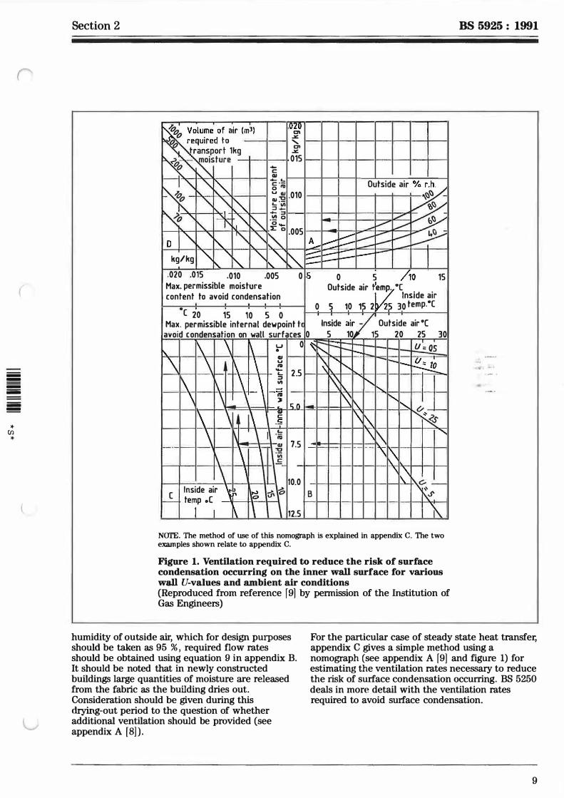
NCJI'E. The method of use of this nomograph is explained in appendix C. The two examples shown relate to appendix C.
Figure 1. Ventilation required to reduce the risk of surface condensation occurring on the inner wall surface for various wall U-values and ambient air conditions (Reproduced from reference f 9] by permission of the Institution of Gas Engineers)
BS 5925 : 1991
humidity of outside air, which for design purposes should be taken as 95 % , required flow rates should be obtained using equation 9 in appendix B. It should be noted that in newly constructed buildings large quantities of moisture are released from the fabric as the building dries out. Consideration should be given during this drying-out period to the question of whether additional ventilation should be provided (see appendix A [8]).
For the particular case of steady state heat transfer, appendix C gives a simple method using a nomograph (see appendix A r9] and figure 1) for estimating the ventilation rates necessary to reduce the risk of surface condensation occurring. BS 5250 deals in more detail with the ventilation rates required to avoid surface condensation.
9
BS 5925 : 1991
4.6 Provision of air for fuel-burning appliances
4. 6.1 General provisions
An air supply to a fuel-burning appliance is required for one or more of the following purposes:
(a) to supply air for combustion and correct flue operation; (b) to limit the concentration of combustion products within the spaces to an acceptable ievel (this is normally taken to be 0.5 % C02); (c) to prevent overheating of the appliance(s) and its surroundings.
4.6.2 Air supply
The supply rate necessary to provide air for typical open-flued domestic fuel-burning appliances, both for combustion and for adequate operation of the flue, is in the range of 0.4 IJs to 30 IJs per kW output of the appliance according to the appliance efficiency. (For gas appliances see BS 5440 : Part 2. For oil-burning appliances see BS 5410 : Parts 1 and 2. For solid-fuel-burning appliances see BS 8303.) N (Jl'F, 1. Modem gas-burning condensing boilers typically require around 0.4 Us per kW output whilst gas-burning decorative fuel effoct appliances may require up to about 30 Lis per kW output. Other appliances with open flues tend to have air supply requirements in the range 0.8 Us to 3.5 Us per kW uutvut.
Section 2
NOfE 2. The air supply required for appliances burning solid fuel is usually in the range given in 4.6.2. However, the requirement is more commonly specified in terms of the free area of a ventilator in the room or space containing the appliance. A solid-fuel-burning open appliance requires an air entry opening with a free area of at lea.st 50 % of the appliance throat-opening area as defined in RS 8303. Other solid-fuel appliances require an air entry opening with a total free area of at least 660 mm2 per kW of rated output above 5 kW. Where a draught stabill.2er is used the total free area should be 300 mm2 for each kW of rated output.
4.6.3 Control of concentration of combustion products
This applies to flueless combustion appliances where the products of combustion pass into the room or space containing the appliance. Flueless appliances are categorized as:
(a) continuous, such as kerosine or gas space heaters; (b) intennittent, such as gas water heaters and cookers.
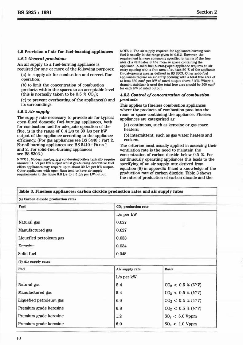
The criterion most usually applied in assessing their ventilation rate is the need to maintain the concentration of carbon dioxide below 0.5 %. For continuously operating appliances this leads to the specifying of an air supply rate derived from equation (9) in appendix Band a knowledge of Lhe production rat.P. of carbon dioxide. 'Thble 3 shows the rates of production of carbon dioxide and the
'Th.hie 3. Flueless appliances: carbon dioxide production rates and air supply rates
(a) Carbon dioxide production rates
Fuel C02 production rate
IJs per kW
Natural gas 0.027
Manufactured gas 0.027
Liquefied petroleum gas 0.033
Ke re sine 0.034 Solid fuel 0.048
{b) Air supply rates
Fuel Air supply rate Bw.iR
Us per kW
Natural gas 5.4 C02 < 0.5 % (VIV)
Manufactured gas 5.4 C02 < 0.5 % (VIV)
Liquefied petroieum gas 6.6 C02 < 0.5 % (VIV)
Premium grade kerosine 6.8 C02 < 0.5 % (VIV)
Premium grade kerosine 1.2 S02 < 5.0 Vppm
Premium grade kerosine 6.0 S02 < 1.0 Vppm
10
('
(
= iiiii iiiii iiiii �
* (/) *
Section 2
derived air flow rates for kerosine, liquefied petroleum gas and natural gas. NCJI'E 1. Fbr kerosine, another criterion should be applied, which is the need to maintain the concentration of sulphur dioxide below a recommended level. The value for air supply rate based on this criterion is also given for a premiwn grade kerosine (class Cl) containing 0.04 % sulphur and with a limiting sulphur dioxide concentration of 5.0 Vppm (the short-term exposure limit) and 1 .0 Vppm (for continuous exposure of the general population). There is a standard grade kerosine available (class C2), with sulphur content up to 0.2 % , which should not be burned in flueless domestic heating appliances.
For gas appliances which are likely to be operated intermittently for limited periods of time, a lower outside air supply rate is permissible since it is only necessary to ensure that the level of carbon dioxide concentration does not exceed 0.5 % during the period of operation of the appliance. Manufactured gas and natural gas produce 0.027 Lis of carbon dioxide per kW heat input. Thus, equation (7) in appendix B should be used in order to determine the ventilation rate, given the length of the period of operation of the appliance. It will be noted that room volume is required for this calculation. For a given heat output the ventilation requirement will increase with decreasing room volume.
NCJI'E 2. Direct-fired air heaters are covered in BS 6230.
4.6.4 Appliances in conflned spaces
Consideration should be given to the provision of an air supply to heating appliances in confined spaces, to prevent overheating of such appliances and of their surrounding enclosures. NCJI'E. For further guidance reference should be made to BS 5410 : Parts 1 and 2, BS 5440 : Part 2 and to appendix A (10).
4. 7 Control of thermal comfort For detailed discussion of the factors which determine the thermal comfort of occupants reference should be made to the CIBSE Guide (see appendix A [ 1 1] ). Thermal comfort is also discussed in reference appendix A ( 12). Indoor temperature is a prime determinant of comfort and this depends upon a number of factors including the use of heating (or cooling) plant, adventitious thermal gains, the thermal characteristics of the building and the ventilation rate. A range of methods, largely computer-based, is available (see appendix A [ 13]) which allow ventilation rate to be related to comfort for any particular building and conditions. A simplified approach is given in CIBSE Guide (see appendix A [ 14] ).
4.8 Removal of smoke resulting from an accidental fire
A fire can generate large quantities of combustion products, namely hot gases carrying smoke particles and containing toxic or noxious and irritant products (usually referred to as 'smoke') .
BS 5925 : 1991
In the event of a fire within a building, ventilation by natural or mechanical means can be used to limit the spread of these products which could otherwise hinder or prevent escape and thus endanger the lives of the occupants, and restrict or prevent effective rescue and fire fighting by the fire brigade.
For certain kinds of building, provision should be made for:
(a) the removal of smoke from escape routes;
(b) the control of the spread of smoke and the general removal of smoke and heat.
Requirements regarding fire ventilation can arise from statutory regulations, government circulars, conditions of licence, insurance, etc.
Fire ventilation may be required to operate either immediately (i. e. openings automatically operated upon the actuation of a heat- or smoke-sensitive device) or be available for operation as and when required by the fire brigade (e.g. breakable pavement lights or manually operated openings) .
The requirements for ventilation in the event of fire may, on occasion, be incompatible with those for normal ventilation . In most cases,·Jarger flows of air or gases have to be allowed for,".in directions sometimes different from those required for normal ventilation.
·
NCJI'E. Refer to BS 5588 and appendix A (15) for specific recommendations concerning fire ventilation requirements and practice.
5 Application
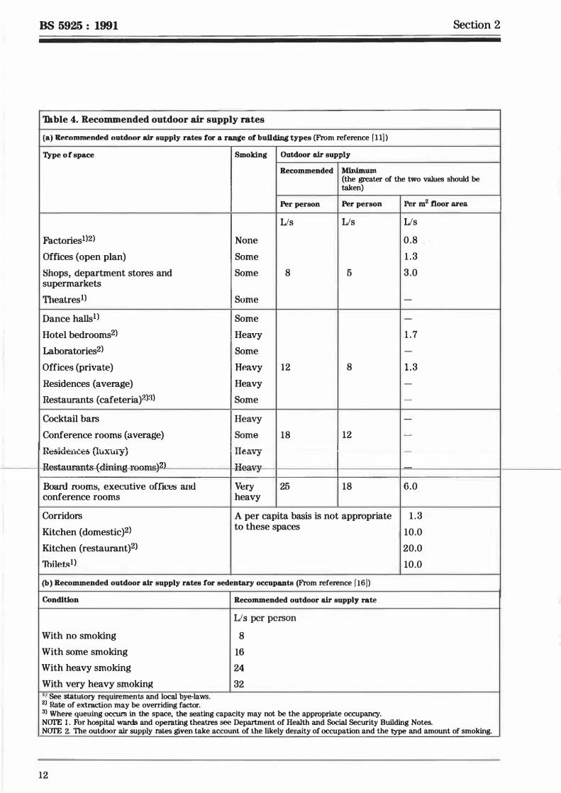
5. 1 General Clause 4 sets out basic data in relation to the main reasons for providing a supply of outside air. In order to determine the required air supply rate for a specific building, or room within a building, these data should be combined with a knowledge of the use to which the building or room is to be put. Tu.ble 4(a) taken from the CIBSE Guide, Volume A 1986, Section Al, lists recommended outdoor air supply rates for a range of building types and these may be used in the initial design process. Tu.hie 4(b) taken from the CIBSE Guide, Volume B 1986, Section B2, has somewhat greater outdoor air supply rates for sedentary occupants, based on recent research which reflects changes in occupants' tolerances of tobacco smoke. Where possible, the designer should calculate outside air requirements on a room-by-room basis in order to obtain a more efficient design. An example is given in appendix D for a domestic living room. In general, the largest rate calculated for the purposes set out in clause 4 defines the required air supply rate. In all cases, however, any calculated rates are subject to the overriding need to satisfy statutory or similar regulations.
1 1
BS 5925 : 1991 Section 2
'Ikble 4. Recommended outdoor air supply rates
(a) Recommended out.door air supply rates for a range of bulldblg types (From reference f l lj)
Type of space Smoking Ont.door air supply
Recommended Minimum (the greater of the two values should be
• taken)
Per person Per person Per m2 fioor area
IJs IJs IJs
Factoriesl)2) None 0.8 Offices (open plan) Some 1 . 3 Shops, department stores and Some 8 5 3.0 supermarkets
Theatres1) Some -
Dance haIIs1) Some -
Hotel bedrooms2) Heavy 1.7
I Laboratories2) Some -
Offices (private) Heavy 1 2 8 1 .3 Residences (average) Heavy -
Restaurants (cafeteria)?.)3) Some -
Cocktail bars Heavy -
Conference rooms (average) Some 18 12 -
Rl.:�.i.<lt:lt1.:t:� (luxury) Ileav-y -
"--taw:ants-(4ining-reGm&)2l -He--:· BoanJ rooms, executive offices and Very 25 18 6.0 conference rooms heavy
Corridors A per capita basis is not appropriate 1 .3 Kitchen (domestic)2l to these spaces 10.0 Kitchen (restaurant)2l 20.0 Thilet�l) 10.0 (b) Recommended out.door air supply rates for sedentary occupants (From reference [16])
Condition Recommended outdoor air supply rate ,,
IJs per person
With no smoking 8 -
With some smoking 16 With heavy smoking 24 With very heavy smokinJ( 32 '' See statutory requirements and local bye-laws. 2> Rate of extraction may be overriding factor. 3> Where queuing occurs in the space, the seating capacity may not be the appropriate occupancy. NCJI'E 1 . Fbr hospital wards and operating theatres see Department of Health and Social Security Building Notes. NCJI'E 2. The outdoor air supply rates given take account of the likely density of occupation and the type and amount of smoking.
12
r
(
iiiiiii !!!!!! iiiiiii iiiiiii iiiiiii !!!!!!
* (/) *
Section 2
It was noted in 4.4.1 that many pollutants may be better controlled by methods other than ventilation, in particular by restricting source emission. However, in setting standards for this form of control a basic level of ventilation may be assumed and, for this reason, even unoccupied spaces require some degree of ventilation although this is generally lower than that required when they are in normal use.
5.2 Special applications The provision of ventilation is required in some types of buildings for special applications, examples of which include:
(a) in factories and industrial processes, to remove hot air, toxic and unpleasant contaminants, smoke and products of combustion in the event of a fire;
(b) in garages or enclosed car parks and vehicle tunnels, to remove exhaust gases (particularly carbon monoxide), petrol vapour and smoke in the event of a fire;
(c) in hospitals, to control cross-infection in special care units and to reduce the level of airborne bacteria in operating theatres;
( d) in large commercial kitchens, to remove excess heat, steam and cooking odours;
( e) in underground rooms and floor areas above ground not provided with normally openable windows, to remove smoke in the event of a fire;
(f) in internal common access lobbies and corridors in blocks of flats and maisonettes, to remove smoke resulting from a fire.
NCYI'E. See appendix A ( 16) for specific requirements.
6 Provision for ventilation
6.1 General considerations
6. 1. 1 Methods of ventilation
In order to supply the air flow rates referred to in clause 5, either natural or mechanical ventilation systems can be employed. This clause describes briefly the main characteristics of each system. Factors affecting the choice of system are set out in clause 7.
Section 3 deals in detail with the design of natural ventilation systems, while the general design, planning and installation of mechanical systems is covered by BS 5720 and appendix A (17) and ( 18).
6.1.2 lnflltration
The uncontrolled exchange of air through adventitious openings in the envelope of a building, such as cracks around windows or at the junction of building components, is termed air infiltration. It is present to varying degrees in nearly all buildings,
BS 5925 : 1991
including those that are mechanically ventilated, unless special attention has been paid to the design and to quality control during building to ensure an airtight structure. Infiltration contributes to the total ventilation rate, but because it is uncontrolled its usefulness can be limited. The general physical processes governing infiltration are the same as those governing natural ventilation, set out in section 3 , except that the characteristics of the flow paths are not well defined.
A method of measuring air leakage in order to estimate infiltration performance, applicable to housing, is set out in clause 15.
6.1.3 Inlets and outlets
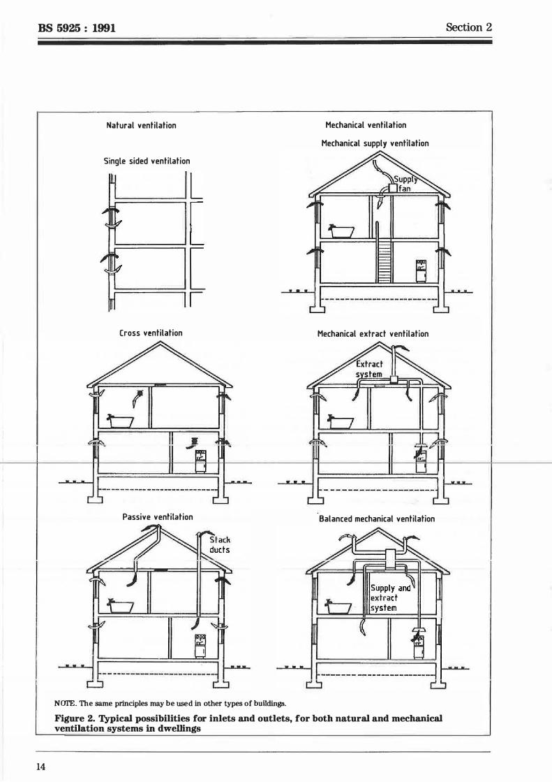
Regardless of the method employed for ventilation, the supply of fresh air to a space should be complemented by provision for the removal of an equal quantity of air from the space. In general, air inlets and outlets are separate, although significant air exchange can occur through a single large opening under certain conditions (see 13.2). Figure 2 shows typical possibilities for inlets and outlets, for both natural and mechanical ventilation systems.
6. 1.4 Natural ventilation
Natural ventilation is the movement of air through openings in the building fabric, due to wind or to static pressures created by differences in temperature between the interior and exterior of the building (generally known as 'stack' effect), or to a combination of these acting together. The mechanisms of natural ventilation are described in detail in section 3, but it should be noted here that natural ventilation is subject to the variability of wind speed, wind direction and air temperature. Not only do these affect the rate of fresh air supply, but they also determine whether any opening will act as an inlet or outlet for the air in any space within the building.
6. 1. 5 Mechanical ventilation
There are several methods of mechanical ventilation, the simplest being the supply or extraction of air fro11 a space using a fan. In these cases an adequate opening should be supplied to allow the exit or entry of air, in order that the fan can operate satisfactorily. More complex systems involve the use of ducted air supply from centrally located fans, possibly providing supply and extraction of air, conditioning of the air and heat recovery from the extracted air.
The main advantage of mechanical ventilation is its controllability. In principle a mechanical system can be designed to satisfy the air requirements of any space within specified limits. In practice, constraints on its use are cost and space limitations.
13
BS 5925 : 1991
14
Natural ventilation Mechanical ventilation
Mechanical supply ventilation
Single sided ventilation
.._____. L ...._____.[ =========: [
I
Cross ventilation Mechanical extract ventilation
Passive ventilation Balanced mechanical ventilation
�---------------------1t NCJI'E. The same principles may be used in other types of buildings.
Figure 2. Typical possibilities for inlets and outlets, for both natural and mechanical ventilation systems in dwellings
Section 2
(
-!!!!! -----!!!!!
* (/)
*
Section 2
6. 1.6 Effects of ventilation
The main effect is the satisfaction of the recommendations set out in clause 5, by providing outside air for dilution or to make up for the extraction of any contaminant at its source. The introduction of air from outside a space can affect the movement of air within the space. These aspects are discussed more fully in 6.2 and 6.3. In addition, it should be noted that the introduction of outside air imposes an energy load, and this should be taken into account in the overall design of the building and its services.
6.2 Air supply
6.2. 1 General
The purposes of ventilation are to ensure correct operation of combustion appliances, and to dilute airborne pollutants. In calculating the required flow rates for pollutant dilution it is assumed that:
(a) steady state conditions apply; and
(b) the pollutant mixes perfectly with the supplied air.
It should be recognized that these assumptions may not apply in all circumstances.
6.2.2 Intermittent pollutant emission
Equation (7) in appendix B governs the change of pollutant concentration with time in a ventilated space for a pollutant emitted at a constant rate. The equilibrium concentration is determined only by the emission rate and the ventilation rate. The time taken to approach equilibrium is determined, however, by the ratio of the ventilation rate to the volume of the space, generally termed the air change rate . This is sometimes used as an alternative means of expressing a ventilation requirement where space volumes are known.
If the production of the pollutant is halted after a finite period of time, then the limiting concentration may not have been reached. This allows the possibility that minimum ventilation rates may be reduced for spaces in which pollutant emission takes place for only limited periods, as in the case of spaces, such as school halls, which may be occupied to full capacity for short periods during the day. Appendix B contains a simple method which allows the possible reduction to be calculated as a function of the period of emission and the space volume.
6.2.3 Ventilation ejjectiveness
The assumption that airborne pollutants are mixed uniformly throughout a ventilated space may not be true. Adequate mixing depends upon the condition of the supplied air and the location of entry points vis-a-vis the source of the pollutant.
BS 5925 : 1991
In some cases the difference in density of the pollutant may encourage the formation of a stable layer which resists mixing with the air in the remaining part of the space.
In a naturally ventilated space good mixing can be promoted by appropriate distribution of the inlets and outlets. In mechanical systems attention may need to be paid to the design and position of supply and extract openings and the expected range of operating conditions to ensure good mixing under all circumstances. Attention should be paid to barriers within the space which might inhibit mixing.
6.3 Air movement
6.3. 1 General
The method of air supply to a space, together with other sources of air movement in the space, such as hot and cold surfaces, can contribute to the movement of air and hence to the pattern of speed and temperature.
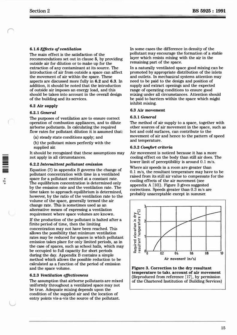
6.3.2 Comfort criteria
Air movement is noticed because it has a more cooling effect on the body than still air does. The lower limit of perceptibility is around 0. 1 mis.
Where air speeds in a room are greater than 0. 1 mis, the resultant temperature may have to be raised from its still air value to compensate for the cooling effects of the air movement (see appendix A f lO] ) . Figure 3 gives suggested corrections. Speeds greater than 0.3 mis are probably unacceptable except in surnnier.
3�����-.-��....-�--��-. G >, O ... -
I -c cu
I 4 I C L. I ::> · ·- � c "' 0 L. ·- QI ...... a. � E cu cu - ...... cu ...... "C c cu "' L. ...... ·5 3 CT VI cu cu 01
02 0:: L.. 0 . Air movement (mis)
Figure 3. Correction to the dry result.ant temperature to t.akl. account of air movement (Reproduced from reference [ 17] , by permission of the Chartered Institution of Building Services)
15
BS 5925 : 1991 Section 2
7 Choice between natural and mechanical ventilation
7. 1 Influencing factors
7. 1. 1 General
The basic factors which influence the choice between natural and mechanical systems are the quality! quantity and controllability of the ventilation.
its use is more appropriate in narrow buildings with limited internal partitioning. If necessary, such buildings could be aligned to gain maximum effect from the prevailing winds. The variability of natural ventilation arising from the dependence on the weather means that it is not suitable for applications requiring consistent flow rates. It follows that the acceptable degree of variation from the design requirement is a major determinant affecting the choice of natural ventilation.
7. 1.2 Quality 7.2.3 Controllability
There is often a difference between the cleanliness Precise control is not achievable with natural of the outdoor air and that indoors. Where the ventilation. Coarse control can be effected with outdoor air is particularly polluted or where clean openable windows, for example, but changes in air is required induurs, the incoming ventilation air speed and direction of the wind impose needs to be filtered. In applications where the considerable fluctuations in flow rate. Further exhaust air is significantly contaminated, filtration information may be found in appendix A (17). to remove the offending pollution is required . . . before the air is discharged to outdoors. 7.3 Need for mechamcal ventllat1on
7. 1.3 Quantity 7. 3. 1 Absolute necessity
Clauses 4 and 5 give information on the fresh air Mechanical ventilatio.n
. is an a�sol�te ne�essity in
flow rates required for rooms or spaces within rooms or spaces req1 . .nnng ventilation which cannot
buildings. In the less critical situations some be adequately supplied by natural means, such as:
variation in the rate of ventilation may be (a) industrial or other premises where it is tolerable. essential to remove dust, toxic or noxious
7 1 0 ll b "l " contaminants at or near to their source;
. . 4 ontm a i ity (b) h
. 1 h · · ·al 1 . . . . . . ospita s w ere It IS essentI to contro cross-�n so�e circumstances vanat1on m vent1l�t10n rate infection, for instance in special care units, and
1s desirable. For example, where substantial to reduce the level of airborne bacteria in changes in numbers of occupants occurs, operating theatres· economies can be achieved by changing the rate of , , ,
' , . • . .
ventilation accordingly. In other cases, control of \.CJ w_u.t::rt:: w1favuw:-d.u1t:: t::XLt::n1a1 t::�1v1rum�1t::11L
___ the..di.re.ction. .of...aiJ;.j'lo:w,...from-clean-.to-less...clean cond1t1ons, e.g. n01se, dust, pollution, eXISt;
areas, may be a specific requirement. ( d) garages or enclosed car parks and vehicle
. . . . . lum1els, in ur<ler lu remuve exhaust gases, 7.2 Lbmtat1ons of natural ventilat1on particularly carbon monoxide, petrol vapour and
7.2. 1 Quality smoke in the event of a fire.
1 The scope for filtering or treating the supply of 7.3.2 Desirability exhaust air is very limited with natural ventilation. Situations where it is desirable that mechanical This is because the flow-inducing pressures ventilation should be provided are as follows· involved are low, so any increase in resistance to . . . .
·
flow. for examnle imnoserl hv filters. would (a) factones and mdustnal processes m order to
substantially r�duce the effe�tivene� of natural remove contaminants;
ventilation. (b) dwellings, in order to remove odours and
7.2.2 Quantity
In theory, almost any required quantity of outside aii can be supplied b;T natural 'lentilation but, as recommended in 6. 1.4, account should be taken that this method is subject to practical limitations, in particular the variability of weather conditions. A low overall resistance to air flow is required to maximize the effectiveness of natural ventilation so
16
excessive moisture from bathrooms and kitchens;
( c) assembly halls and lecture theatres where a high density of occupation is expected;
(d) situations where wind and stack effect might render natural ventilation impracticable, as with some tall buildings;
(e) large commercial kitchens.
(
iiii !!!!!! iiii iiii iiii !!!!!!
* [/) *
Section 3 BS 5925 : 1991
Section 3. Natural ventilation
8 General The purpose of this section is to outline the physical processes which govern natural ventilation and to illustrate these for simple cases. The equations which describe these processes can be combined with meteorological data and building characteristics (such as the size and positions of air flow paths in the building envelope) in models which allow natural ventilation rates to be calculated. For all but the simplest situations the necessary calculations will be best performed by computer. These models may be used to give guidance on the areas of opening required to ensure that fresh air requirements are satisfied.
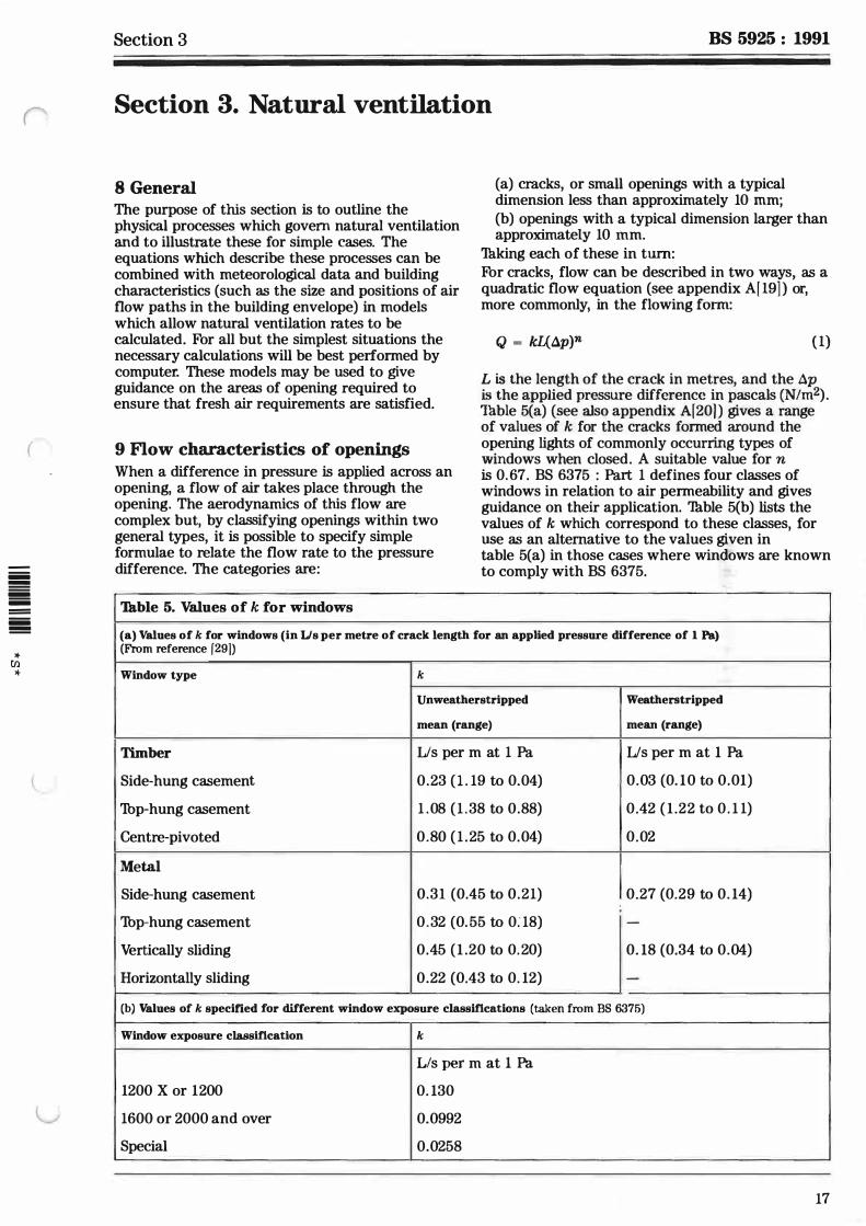
9 Flow characteristics of openings When a difference in pressure is applied across an opening, a flow of air takes place through the opening. The aerodynamics of this flow are complex but, by classifying openings within two general types, it is possible to specify simple formulae to relate the flow rate to the pressure difference. The categories are:
Tu.hie 5. Values of k for windows
(a) cracks, or small openings with a typical dimension less than approximately 10 mm; (b) openings with a typical dimension larger than approximately 10 mm.
Tu.king each of these in turn: For cracks, flow can be described in two ways, as a quadratic flow equation (see appendix A[19] ) or, more commonly, in the flowing fonn:
Q = kl1_6p)n (1)
L is the length of the crack in metres, and the 6p is the applied pressure difference in pascals (N/m2). Tuble 5(a) (see also appendix A[201 ) gives a range of values of k for the cracks formed around the opening lights of commonly occurring types of windows when closed. A suitable value for n is 0.67. BS 6375 : Part 1 defines four classes of windows in relation to air permeability and gives guidance on their application. Thble 5(b) lists the values of k which correspond to these classes, for use as an alternative to the values given in table 5(a) in those cases where windows are known to comply with BS 6375.
(a) Values of k for windows (in IJs per metre of crack length for an applied pressure difference of 1 Pa) (From reference f 29])
Window type k Unweatherstripped Weatherstripped
mean (range) mean (range)
Timber Us per m at 1 Pa Us per m at 1 Pa
Side-hung casement 0.23 (1 . 19 to 0.04) 0.03 (0. 10 to 0.01)
'lbp-hung casement 1 .08 (1 .38 to 0.88) 0.42 ( 1 .22 to 0 . 1 1)
Centre-pivoted 0.80 (1 .25 to 0.04) 0.02
Met.al
Side-hung casement 0.31 (0.45 to 0.21) 0.27 (0.29 to 0. 14) :
'lbp-hung casement 0.32 (0.55 to 0: 18) -
Vertically sliding 0.45 (1 .20 to 0.20) 0. 18 (0.34 to 0.04)
Horizontally sliding 0.22 (0.43 to 0. 12) -
(b) Values of k specified for different window exposure classifications (taken from BS 6375)
Window exposure classification k
L/s per m at 1 Pa
1200 X or 1200 0. 130
1600 or 2000 and over 0.0992
Special 0.0258
17
BS 5925 : 1991
For larger openings:
Q = C<tA(2.dplp)1h (2)
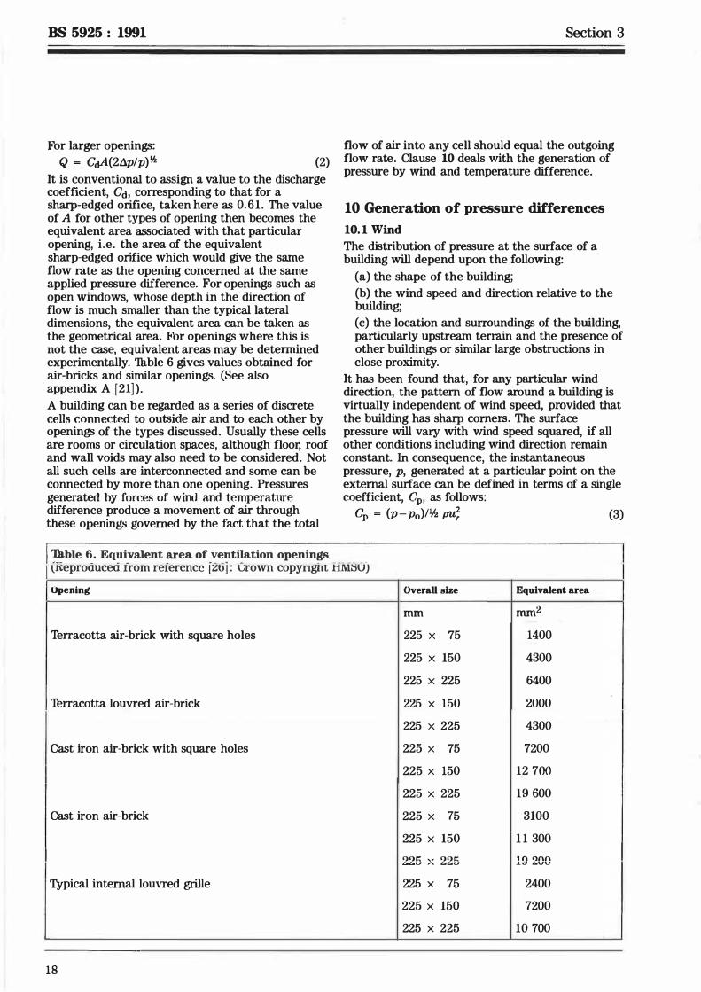
It is conventional to assign a value to the discharge coefficient, Cd, corresponding to that for a sharp-edged orifice, taken here as 0.61 . The value of A for other types of opening then becomes the equivalent area associated with that particular opening, i.e. the area of the equivalent sharp-edged orifice which would give the same flow rate as the opening concerned at the same applied pressure difference. For openings such as open windows, whose depth in the direction of flow is much smaller than the typical lateral dimensions, the equivalent area can be taken as the geometrical area. For openings where this is not the case, equivalent areas may be determined experimentally. Thble 6 gives values obtained for air-bricks and similar openings. (See also appendix A [21] ) .
A building can be regarded as a series of discrete cells c.onnected to out5ide air and to each other by openings of the types discussed. Usually these cells are rooms or circulation spaces, although floor, roof and wall voids may also need to be considered. Not all such cells are interconnected and some can be connected by more than one opening. Pressures generated hy forces of wind and temperature difference produce a movement of air through these openings governed by the fact that the total
Section 3
flow of air into any cell should equal the outgoing flow rate. Clause 10 deals with the generation of pressure by wind and temperature difference.
10 Generation of pressure differences
10. 1 Wind The distribution of pressure at the surface of a building will depend upon the following:
(a) the shape of the building;
(b) the wind speed and direction relative to the building;
(c) the location and surroundings of the building, particularly upstream terrain and the presence of other buildings or similar large obstructions in close proximity.
It has been found that, for any particular wind direction, the pattern of flow around a building is virtually independent of wind speed, provided that the building has sharp comers. The surface pressure will vary with wind speed squared, if all other conditions including wind direction remain constant. In consequence, the instantaneous pressure, p, generated at a particular point on the external surface can be defined in terms of a single coefficient, Gp, as follows:
Gp = (p -p0)11h pu; (3)
I �hie �· Eq�i_:valent �ea of .".'�!lti!ation openin�s _ __ _ _ _ _
l.treproaucea rrom rerercncc [�t>J : vrown copyngnt tlM�UJ
Opening Overall size Equivalent area
mm mm 2
Turracotta air-brick with square holes 225 x 75 1400
225 x 150 4300
225 x 225 6400
Turracotta louvred air-brick 225 x 150 2000
225 x 225 4300
Cast iron air-brick with square holes 225 x 75 7200
225 x 150 12 700
225 x 225 19 600
Cast iron air-brick 225 x 75 3100
225 x 150 1 1 300
'>'>I': " '>'> J:: 19 200 L.u: .... u "' ��u
Typical internal louvred grille 225 x 75 2400
225 x 150 7200
225 x 225 10 700
18
(
iiii !!!!!! iiii iiii iiii !!!!!!
* u.i *
Section 3
Po is the static pressure in the free wind, and Ur is the reference wind speed, conventionally taken as the speed of the undisturbed wind at a height equal to that of the building under consideration. The surface pressure varies with time, due to turbulence in the free wind and that created by the building itself, or by upstream obstructions, but for present purposes the mean value is used.
NarE. A brief discussion of the effect of pressure fluctuation on ventilation rate is included in clause 13.
If the mean values of surface pressure and surface pressure coefficient are written as p and q;, equation (3) may be rearranged to give:
P = Po + q; (1h PUr2) (4)
Once the distribution of q, has been determined for a single wind speed and particular wind direction, then surface pressure can be calculated readily for any other wind speed. Th illustrate the general magnitudes of cl!, table 7' taken from CP 3 : Chapter V : Part � : 1972, contains values for very simple building shapes. Most buildings are considerably more complex than these and are generally surrounded by other buildings or obstructions. Th determine detailed distributions of pressure coefficient it will be necessary to resort to wind tunnel tests on scale models.
BS 5925 : 1991
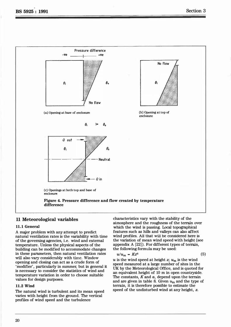
10.2 Tumperature difference Air density varies approximately as the inverse of absolute temperature. The weight of two vertical columns of air at different temperatures, separated from each other by a vertical surface, differs and a pressure difference across the surface results. Thus, if the air temperature within a building is higher than that outside, pressure difference creates an air flow through openings in the intervening fabric. Figure 4 illustrates the action of this pressure difference for a simple enclosure with one or two small openings. With a small single opening, no flow takes place. With two openings, air flows in at the lower opening and out at the upper opening, because the internal temperature is higher than that outside the enclosure. The pressure difference across the wall of the enclosure becomes such as to ensure that the inflow equals the outflow. The level at which the pressure difference is zero is known as the 'neutral' level.
Tuble 7. Typical magnitudes of pressure created by wind and temperature difference
(a) Wind
Wind speed ( u,.) Pressure
Cp = 0. 1 CP = 0.3 cp = 0. 1> op = 1.0
mis Pa Pa Pa Pa
1 .0 0.06 0. 18 0.30 0.59
4.0 0.94 2.83 4.72 9.44
7.0 2 .89 8.67 14.45 28.91
10.0 5.90 17.70 29.50 59.00 '
(b) Tumperature difference
Thmperature Pressure difleren.ce
H1 = l m H1 = 3 m f/1 = 6 m H1 = !O m 111 = 50 m //1 = lOO m K Pa Pa Pa Pa Pa Pa
1.0 0.04 0. 12 0.24 0.40 2.02 4.05
4.0 0.16 0.49 0.98 1 .64 8. 18 16.36
10.0 0.42 1 .25 2.51 4. 18 20.88 41 .76
20.0 0.87 2.60 5.20 8.66 43.29 86.59
19
BS 5925 : 1991
-Ve
Oi
Pressure difference +Ve
(a) Opening at base of enclosure
(Ji > Bo
a out
-1t\IP;vo, (}j '"· ,. ·�!I - - Neutral
&�,1rill � a in
(c) Openin� at both top and base of enclosure
No flow
{}j
(b) Opening at top of enclosure
Section 3
Figure 4. Pressure difference and flow created by temperature difference
11 Meteorological variables
11. 1 General A major problem with any attempt to predict natural ventilation rates is the variability with time of the governing agencies, i.e. wind and external temperature. Unless the physical aspects of the building can be modified to accommodate changes in these parameters, then natural ventilation rates l\ill also var/ corisidcrably \vith th'llc. \l/indo\v opening and closing can act as a crude form of 'modifier' , particularly in summer, but in general it is necessary to consider the statistics of wind and temperature variation in order to choose suitable values for design purposes.
11.2 Wind The natural wind is turbulent and its mean speed varies with height from the ground. The vertical profiles of wind speed and the turbulence
20
characteristics vary with the stability of the atmosphere and the roughness of the terrain over which the wind is passing. Local topographical features such as hills and valleys can also affect wind profiles. All that will be considered here is the variation of mean wind speed with height (see appendix A f22] ) . For different types of terrain, the following formula may be used:
ulu.n - KZL (5) u is the wind speed at height z; Um is the wind speed measured at a large number of sites in the UK by the Meteorological Office, and is quoted for an equivalent height of 10 m in open countryside. The constants, K and a, depend upon the terrain and are given in table 8. Given Um and the type of terrain, it is therefore possible to estimate the speed of the undisturbed wind at any height, z.
iiiiiiiiii � !!!!!!!!! -iiiiiiiiii �
* (/) *
Section 3
'Tu.ble 8. Factors for determining mean wind speed at different heights and for different types of terrain from the Meteorological Office wind speed, Urn. measured at 10 m in open country (Reproduced from reference [26] : Crown copyright HMSO)
Turrain K a
Open flat country 0.68 0. 17
Country with scattered wind 0.52 0.20 breaks
Urban 0.35 0.25
City 0.21 0.33
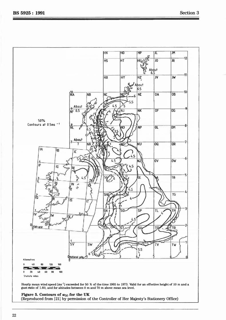
It is now necessary to consider the geographical and statistical variation of Urn. Data on mean wind speed has been condensed (see appendix A [23]) to provide a description of the cumulative frequency of wind speed in terms of the wind speed exceeded for 50 % of the time at a particular site. This value of Urn will be ref erred to as u50. Figure 5 is a map of the UK showing contours of u50. Used in conjunction with the frequency distributions given in table 9, it is possible to determine the value of um exceeded for any chosen proportion of time at any site in the UK. In order to obtain this simplified relationship it has been assumed that the frequency distribution of wind speed at any site is independent of wind direction. This varies considerably at most sites in the UK but predominant directions can be obtained from wind 'rose' maps (see appendix A [24] ) .
'Tu.hie 9. Values of the ratio of mean wind speed exceeded for a given percentage of time to the 50 % mean wind speed u50 (Reproduced from reference [26] : Crown copyright HMSO)
Percentage Location
Exposed coastal Sheltered inland
80 0.56 0.46
75 0.64 0.56
70 0.71 0.65
60 0.86 0.83
50 1 .00 1.00
40 1 . 15 1 . 18
30 1 .33 1 .39
25 1 .42 1 .51
20 1 .54 1 .66
15 1 .70 1 .80
10 1 .84 2.03
BS 5925 : 1991
The preceding information enables the reference wind speed, Uri defined in clause 10, to be estimated for any given site . Appendix E illustrates this by means of a simple example.
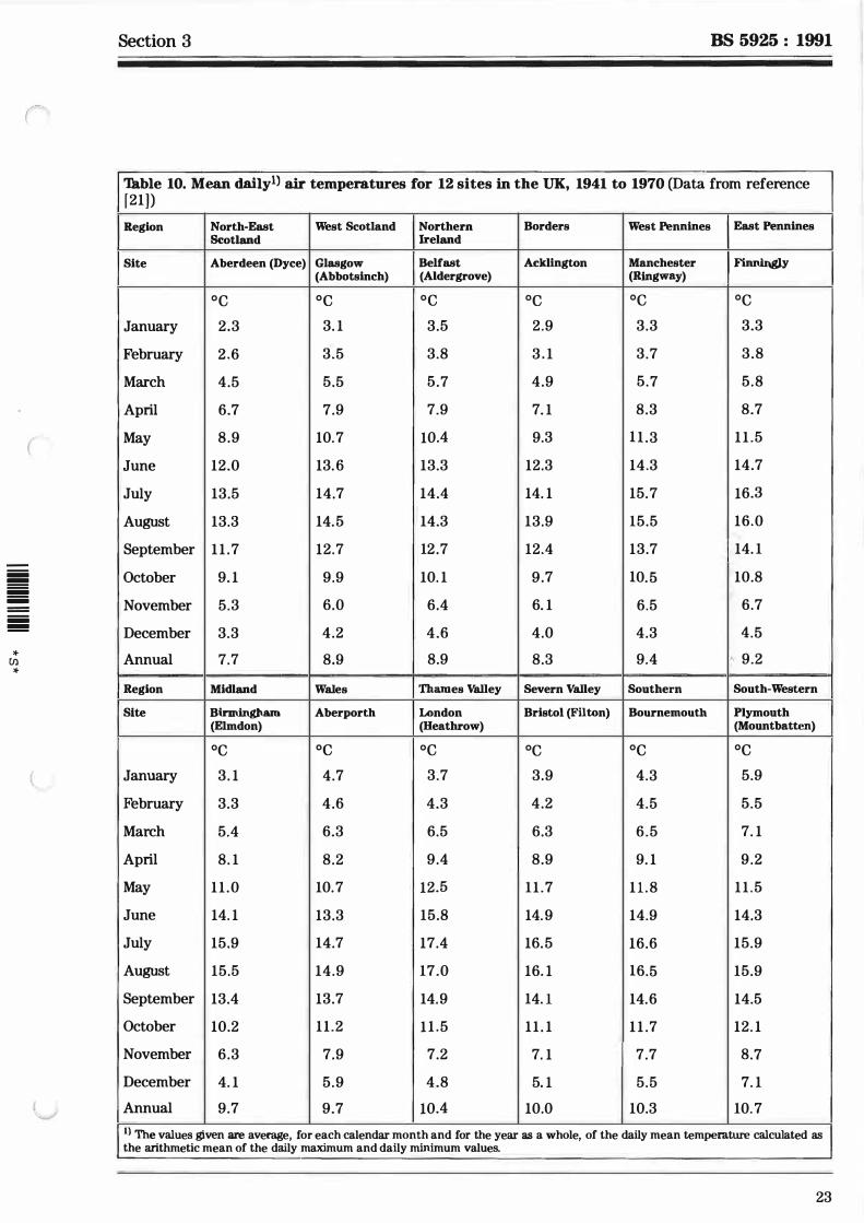
11.3 Tumperature Ambient air temperature varies diurnally and from day to day, but can, for present purposes, be characterized by a monthly mean and a monthly mean daily variation for any particular site. Thble 10 shows the monthly mean air temperature for 12 sites. For further data see appendix A (25), (26) and (27). An indication of the way in which the temperature varies over 24 h can be obtained from appendix A (24) which shows the daily mean temperature variation for Heathrow, London, together with the standard deviation associated with these means. For design purposes it is suggested that the monthly mean value be used.
12 Determination of natural ventilation rates
12.1 General considerations In principle, the foregoing information enables the air flow through a building and , in consequence, the ventilation rate of spaces within the building to be estimated for a given wind speed and direction, provided that the following are known:
(a) the position and flow characteristics of all openings;
(b) the detailed surface mean pressure coefficient distribution for the wind direction under consideration;
(c) the internal and external air temperatures.
Because, in order to predict ventilation rates, in all but the simplest cases, a large number of non-linear simultaneous equations require to be solved, it is generally necessary to use a computer. Programs exist but the value of the results which they produce will depend upon the accuracy of the data listed in (a), (b) and (c) above. It is rare that these are known in detail for existing buildings, let alone at the design stage. General data on many relevant factors are contained in appendix A (28), which also summarizes a range of calculation techniques. However, more information is required on the pressure distributions for typical building arrangements and the position and flow characteristics of openings.
The general characteristics of natural ventilation can, however, be demonstrated by considering some simple cases. Figure 6 shows a simple, ' two-dimensional' representation of a building with no internal divisions, and therefore consisting of a single cell, with openings as shown, i.e. two (A 1 and A3) at high level, and two (A2 and A4) at low level. These openings will be considered to be large and, consequently, the flow through them will be
21
BS 5925 : 1991 Section 3
22
50% Contours at O.Sms - 1
'" l1a
4 r IF
HS HT H' r Ab ut 6.
HX HY HZ .
jf� . / A'"''"'1 1 f. tf, _ �
NC
!"' <Jr�f· � L�L ;. •� .. [�!.,- - � I(� t : .. � .. 1 �-KP". 0 7/ NP
i:, Ab;ut INR���� �INu �� ML ' I� • s.s - .,, 4.5 '·5 Nil
JV
OA
OF I l oL ioa lov
JR 12
JW 11
OB
OG 9
loM 8
ioR 7
low 6
J P.I� )}Ji)��, �� '4. I. s . s "l'r... ,.j E:. � Ira IL ,Ge�.
Kilometres 40 80 120 160
- - - ._ - - - ... -20 40 60 80 100
Statute miles
.,.
�N .; /'�/ I Ji)it: I n � I TG 4
"' 3
I ,.....,.,y '!.:x:' c:I .. "' ,,,., Y- / I � F-J. 2
�v l c1.1 1�l fA?���ITU !
Hourly mean wind speed (rns-1) exceeded for 50 % of the time 1965 to 1973. Valid for an effective height of 10 rn and a gust ratio of 1.60, and for altitudes between 0 m and 70 m above mean sea leveL
Figure 5. Contours of u50 for the UK (Reproduced from f21l by permission of the Controller of Her Majesty's Stationery Office)
(
� !!!! � � � !!!!
* [/) *
Section 3 BS 5925 : 1991
'Jkble 10. Mean dailyl) air temperatures for 12 sites in the UK, 1941 to 1970 (Data from reference f21])
Region North-East West Scotland Northern Borders West Pennines East Pennines Scotland Ireland
Site Aberdeen (Dyce) Glasgow Belfast Ackllngton Manchester Finningly (Abbotsinch) (Aldergrove) (Ringway)
oc oc oc oc oc oc January 2.3 3. 1 3.5 2.9 3.3 3.3
February 2.6 3.5 3.8 3 . 1 3.7 3.8
March 4.5 5.5 5 .7 4.9 5 .7 5 .8
April 6.7 7.9 7.9 7. 1 8.3 8.7
May 8.9 10.7 10.4 9.3 11 .3 11 .5
June 12.0 13.6 13.3 12.3 14.3 14.7
July 13.5 14.7 14.4 14. 1 15.7 16.3
August 13.3 14.5 14.3 13.9 15.5 16.0
September 11 .7 12.7 12 .7 12.4 13.7 14. 1
October 9. 1 9.9 10. 1 9.7 10.5 10.8
November 5.3 6.0 6.4 6. 1 6.5 6.7
December 3.3 4.2 4.6 4.0 4.3 4.5
Annual 7.7 8.9 8.9 8.3 9.4 9.2
Region Midland Wales Thames Valley Severn Valley Southern South-Western
Site Birmingham Aberporth London Bristol (Filton) Bournemouth Plymouth (Elmdon) (Heathrow) (Mountbatten)
oc oc oc oc oc oc January 3. 1 4.7 3.7 3.9 4.3 5.9
February 3.3 4.6 4.3 4.2 4.5 5.5
March 5.4 6.3 6.5 6.3 6 .5 7. 1
April 8. 1 8.2 9.4 8.9 9. 1 9 .2
May 11 .0 10.7 12.5 11 .7 11 .8 11 .5
June 14. 1 13.3 15.8 14.9 14.9 14.3
July 15.9 14.7 17.4 16.5 16.6 15.9
August 15.5 14.9 17.0 16. l 16.5 15.9
September 13.4 13.7 14.9 14. l 14.6 14.5
October 10.2 11 .2 1 1 .5 11 . 1 1 1 .7 12. 1
November 6.3 7.9 7.2 7. 1 7.7 8.7
December 4. 1 5.9 4.8 5. 1 5.5 7. 1
Annual 9.7 9.7 10.4 10.0 10.3 10.7
l) The values given are average, for each calendar month and for the year as a whole, of the daily mean temperature calculated as the arithmetic mean of the daily maximum and daily minimum values.
23
BS 5925 : 1991
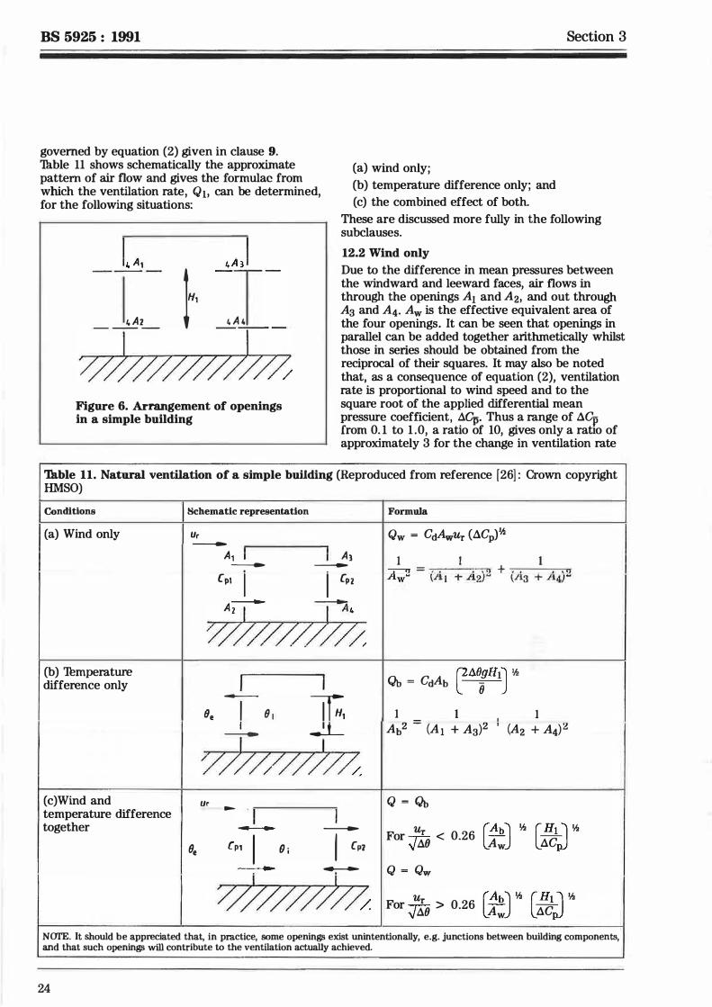
governed by equation (2) given in clause 9. Th.hie 11 shows schematically the approximate pattern of air flow and gives the formulae from which the ventilation rate, Q1, can be determined, for the following situations:
14 A1 4 AJ --- 1H1 • A • � 4 A2
I I > > > Y > > >
Figure 6. Arrangement of openings in a simple building
(a) wind only; (b) temperature difference only; and (c) the combined effect of both.
Section 3
These are discussed more fully in the following subclauses.
12.2 Wind only
Due to the difference in mean pressures between the windward and leeward faces, air flows in through the openings A1 and A2, and out through Aa and A4. Aw is the effective equivalent area of the four openings. It can be seen that openings in parallel can be added together arithmetically whilst those in series should be obtained from the reciprocal of their squares. It may also be noted that, as a consequence of equation (2), ventilation rate is proportional to wind speed and to the square root of the applied differential mean pressure coefficient, aq,. Thus a range of "1Cp from 0. 1 to 1 .0, a ratio of 10, gives only a ratio of approximately 3 for the change in ventilation rate
'Th.hie 11. Natural ventilation of a simple building (Reproduced from reference [26] : Crown copyright HMSO)
Conditions
(a) Wind only
(b) Thmperature difference only
(c)Wind and temperature difference together
Schematic representation
Ur ---
A, I I
8,
A1 --- ---
Cp1 I I Cp2
A --- �
Wm-@�
I I -- If;, Be I 8 1
I � ---
m//,,m� Ur -
· 1 I - - --
[p1 I (} i I (p7 - --
WF$/J.
Formula
Qw = Cc0.wUr ("1Cp)1h
1 I 1 Aw2 = (.A. 1 -t- .A2)!f + (A3 -r A.4)2
�i18gH1J 112 QtJ = Cc0.b -
(}
I 1 I I Ab2 = (A1 + Aa)2 ' (A2 + A4)2
Q = <Jt>
Ur [AbJ � [H1j � For 'J aO < 0.26 Aw i1C
Q = Qw
Ur [ AbJ � [ H1j � For 'J aO > 0.26 Aw i1C NCJI'E. It should be appreciated that, in practice, some openinw; exist unintentionally, e.g. junctions between building components, and that such openinw; will contribute to the ventilation actually achieved.
24
(
iiii !!!! iiii iiii iiii !!!!
* Ul
*
Section 3
for the same wind speed. Higher values of aq, are typical of exposed building whereas lower values are more typical of sheltered buildings.
12.3 Temperature difference only In this case the air flows in at the lower openings A2 and A4 and out through A 1 and Aa. The equivalent area is now Ab. The formula given in table 1 1 shows that ventilation rate is proportional to both temperature difference and height between openings.
12.4 Combined effect of wind and temperature difference For the simple case under consideration, at low temperatures the flow pattern is similar to that for wind alone. If the temperature is increased, keeping wind speed constant, the combined effect of wind and temperature difference is to enhance the flow through the lower windward and upper leeward openings and to reduce the flow in the upper windward and lower leeward openings. Eventually, in this example, the flow in the upper windward and lower leeward openings becomes zero and as the temperature difference increases further it reverses, approaching a flow pattern typical of temperature difference acting alone.
Even for this simple example, the ventilation rate of the space due to the action of both wind and temperature difference is not easy to calculate, but a reasonable approximation can be made by calculating the flow rates expected for the two conditions acting separately and taking the larger to apply to the combined case. For the simple example in figure 5 this leads to the expression Ur!.J.iO given in table 1 1 , which determines whether wind or temperature difference will dominate. The form of this expression indicates that taller, or more sheltered, buildings will tend to have natural ventilation rates independent of wind speed for a large part of the colder months of the year.
An example is given in appendix F, using the formulae given in table 1 1 .
13 Other mechanisms of natural ventilation
13. 1 General Although the mechanisms of natural ventilation discussed in clause 12 apply in most situations, there are cases where other mechanisms are also of importance.
13. 2 Natural ventilation of spaces with openings on one side only
13.2. 1 General
Th assist in dissipating heat and maintaining comfortable conditions, the ventilation rates required in non-air conditioned buildings in summer are higher than those required in winter.
BS 5925 : 1991
These larger rates can usually be obtained readily by cross-ventilation according to mechanisms already discussed , except where large openings are available on one external wall only. Typical such examples are offices, or school classrooms, where internal doors are kept closed for reasons of privacy or noise. In these situations cross-ventilation would be severely restricted by the limited openings around the closed internal doors. In fact, considerable exchange of air can take place at the external wall openings due to the wind or temperature difference.
13.2.2 Wind
Air exchange at a single opening can occur because of the turbulent nature of the air flow, or due to the interaction of the local air flow with the opening light, say of a side-mounted casement window. Thble 12 gives a simple formula which enables the flow rate to be calculated in terms of the open area of a window and the reference wind speed, Ur.
13.2.3 Temperature dij]erence
Tumperature difference acts in the same way for a single room as for a building. The appropriate formulae for two openings, displaced vertically, and for a single rectangular opening are given in table 12. For the single opening, wanner air flows out from the upper part of the opening and colder air in through the lower part of the opening. Figures 7(a) and 7(b) show how the flow through a single opening window is modified by the presence of the opening light, for a side-mounted casement and a centre-pivoted window respectively.
13.2.4 Combined wind and temperature dij]erence
As in the case of cross-ventilation, the ventilation rate due to both effects acting together can be taken as the larger of the two individual rates. NOTE. Appendix A ( 17) contains a graphical approach, based upon tables 1 1 and 12, for calculating ventilation rate for a number of simple building configurations in summer.
13.3 Pressure fluctuation The turbulent nature of the wind, and additional turbulence created by the interaction of the building with the wind, mean that in practice the pressure generated at the surface of a building is not steady but fluctuating. The use of the mean pressures in clause 12 is, therefore, technically incorrect, but the error is small unless the mean pressure difference across an opening is small. Small pressure differences may arise from the effects of shelter, or the orientation of the building to the wind. Consider the example of a terraced house in the situation where the wind is parallel to the line of the terrace. The mean pressures at the two external faces would be equal. In practice turbulence gives rise to pressure fluctuations that can result in air flow through the house from alternating directions. The actual ventilation rate is therefore higher than that indicated by using
25
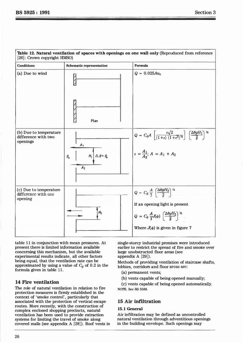
BS 5925 : 1991 Section 3
'18.ble 12. Natural ventilation of spaces with openings on one wall only (Reproduced from reference [26] : Crown copyright HMSO)
Conditions Schematic representation
(a) Due to wind / / / /
:I' / / II II
Plan ,,
{b) Due to temperature I difference with two
openings I A 1 o.J=r·�
Ai
(c) Due to temperature I difference with one opening
.. Hz
table 1 1 in conjunction with mean pressures. At present there is limited information available concerning this mechanism, but the available experimental results indicate, all other factors being equal, that the ventilation rate can be approximated by using a value of Cp of 0.2 in the formula given in table 1 1 .
14 Fire ventilation The role of natural ventilation in relation to fire protection measures is firmly established in the context of 'smoke control' , particularly that associated with the protection of vertical escape routes. More recently, with the construction of complex enclosed shopping precincts, natural ventilation has been used to provide extraction systems for limiting the travel of smoke along covered malls (see appendix A f28] ) . Roof vents in
26
��
Formula
Q = 0.025AUr
[ E./2 J Q = C� ( l +f) ( l +E2)1h
t: = ��; A = Ai + Az
Q = Cd � r.10�n�1 Y.i J \.. 6 -'
It" an opening light is present
Q = Cd 4'c<P) c:\O�H2J v.i
elO�H1J �
Where J( q,) is given in figure 7
single-storey industrial premises were introduced earlier to restrict the spread of tire and smoke over large unobstructed floor areas (see appendix A [29] ) . Methods of providing ventilation of staircase shafts, lobbies, corridors and floor areas arc:
(a) permanent vents;
(b) vents capable of being opened manually;
( c) vents capable of being opened automatically. N<Yl'E. See BS 5588.
15 Air infiltration
15. 1 General Air infiltration may be defined as uncontrolled natural ventilation through adventitious openings in the building envelope. Such openings may
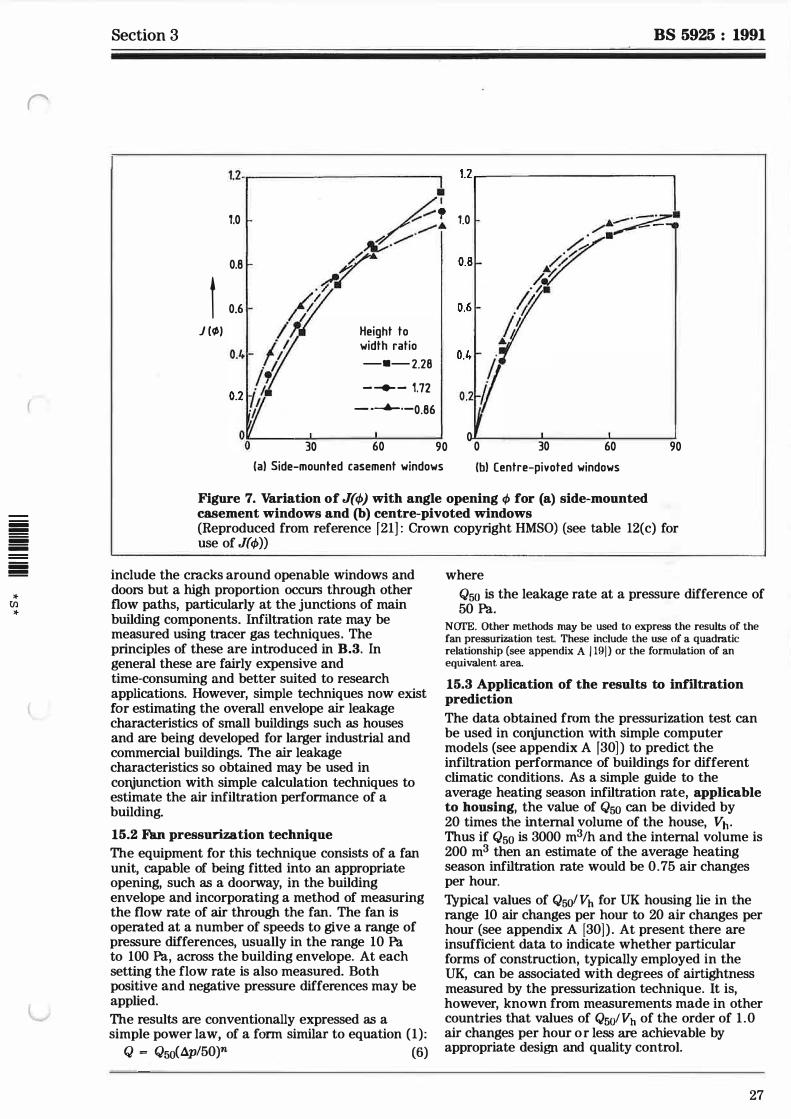
('
iiii � iiii iiii iiii �
* Ul *
Section 3
1.2-.-------------,
1.0
0.8
l 0 6
J (<I>)
30
Height to width ratio
-•-2.28
- -+- - 1.72
- · ......... ·-0.86
60 90
(al Side-mounted casement windows
BS 5925 : 1991
1.2 .-----------.
1.0 l-
�8�
�-
r. �--2 �
A 0.6 1- (x'· . /,
fl 0.4 1- .
. ,l 0
0 30 60
(bl Centre-pivoted windows
90
Figure 7. Variation of J(cp) with angle opening <P for (a) side-mounted casement windows and (b) centre-pivoted windows (Reproduced from reference f21] : Crown copyright HMSO) (see table 12(c) for use of J(cp))
include the cracks around openable windows and doors but a high proportion occurs through other flow paths, particularly at the junctions of main building components. Infiltration rate may be measured using tracer gas techniques. The principles of these are introduced in B.3. In general these are fairly expensive and time-consuming and better suited to research applications. However, simple techniques now exist for estimating the overall envelope air leakage characteristics of small buildings such as houses and are being developed for larger industrial and commercial buildings. The air leakage characteristics so obtained may be used in cortjunction with simple calculation techniques to estimate the air infiltration performance of a building.
15.2 Fan pressurization technique The equipment for this technique consists of a fan unit, capable of being fitted into an appropriate opening, such as a doorway, in the building envelope and incorporating a method of measuring the flow rate of air through the fan. The fan is operated at a number of speeds to give a range of pressure differences, usually in the range 10 Pa to 100 Pa, across the building envelope. At each setting the flow rate is also measured. Both positive and negative pressure differences may be applied. The results are conventionally expressed as a simple power law, of a form similar to equation (1):
Q = Qso("1p/50)n (6)
where
Q50 is the leakage rate at a pressure difference of 50 Pa.
NCJI'E. Other methods may be used to express the results of the fan pressurization test. These include the use of a quadratic relationship (see appendix A / 19j ) or the formulation of an equivalent. area.
15.3 Application of the results to infiltration prediction
The data obtained from the pressurization test can be used in cortjunction with simple computer models (see appendix A [30] ) to predict the infiltration performance of buildings for different climatic conditions. As a simple guide to the average heating season infiltration rate, applicable to housing, the value of Q5o can be divided by 20 times the internal volume of the house, vh. Thus if Q5o is 3000 m3/h and the internal volume is 200 m3 then an estimate of the average heating season infiltration rate would be 0. 75 air changes per hour.
Typical values of Q5o/ Vh for UK housing lie in the range 10 air changes per hour to 20 air changes per hour (see appendix A (30]) . At present there are insufficient data to indicate whether particular forms of construction, typically employed in the UK, can be associated with degrees of airtightness measured by the pressurization technique. It is, however, known from measurements made in other countries that values of Q5olVh of the order of 1 .0 air changes per hour or less are achievable by appropriate design and quality control.
27
BS 5925 : 1991
16 Normal building practice for natural ventilation in dwellings 16. 1 General The results of calculations of the ventilation rates required to control indoor pollutants, as described in appendices B, C and D, may be relied upon with some confidence. However, as noted in 12. 1, the results of ventilation rate prediction calculations depend upon the accuracy of the input data used and it is rare that these data are known in detail for a particular building. Furthermore, the need for computer programs to deal with anything other than simple cases leads to the conclusion that there may often be insufficient benefits to justify making ventilation rate prediction calculations. This is particularly so in the case of small one-off buildings where the c.ost of gathering the required data may be prohibitive. Thus it is appropriate to give some guidance on normal building practice for natural ventilation. Because of the variability of various construction features, such as ceiling heights, surface area/volume ratio, and type of wall construction, this guidance has to be limited to dwellings in which such features are more consistent. The guidance assumes that there exists a typical level of background air infillmtiun lhruugh adventitious openings in the building envelope. In dwellings which are of a type of construction which may be more airtight than normal, such as those with a particularly carefully fitted and jointed polyethylene vapour barrier, it may be necessary to increase the areas of the background ventilation openings to compensate for the reduced background air infiltration. Background air infiltration may be assessed using the method described in clause 15. Statutory and local regulations may be more or less stringent than the recommendations given in 16. 2 and in all cases it is essential that such regulations take precedence. Furthermore, the recommendations of 16.2 may need to be modified tu take; accou.rit of individual .:ircurt15tt.i.11ces; e.g. severity of exposure to weather, airtightness of the building structure, or requirements for protection against ingress of radon, methane or other soil gases. 16.2 Ventilation of dwellings The following ventilation is recommended for rooms and spaces in and around dwellings.
(a) Habitabf,e rooms. For rapid ventilation one or more ventilation openings with a total area of at least l/20th of the floor area of the room and with some part of the ventilation opening at least 1. 75 m above the floor level, e.g. an opening window; and for background ventilation a ventilation opening(s), having a total area not less than 4000 mm2, e.g. a trickle ventilator. The opening(s) should be controllable and secure and located so as to avoid undue draughts.
28
Section 3
(b) Kit;chens. Mechanical extract ventilation for rapid ventilation, rated as capable of extracting at a rate not less than 60 Lis (or incorporated within a cooker hood and capable of extracting at a rate of 30 Lis), which may be operated intermittently for instance during cooking; and either:
(1) background ventilation by a controllable and secure ventilation opening(s) having a total area not less than 4000 m2, located so as to avoid draughts, e.g. a trickle ventilator; or (2) the mechanical ventilation being in addition capable of operating continuously at nominally one air change per hour.
(c) Bathrooms and shower rooms. Mechanical extract ventilation capable of extracting at a rate not less than 15 Lis which may be operated intermittently.
(d) Cmnmon S'paces in lYuildings containing two or more dwellings. Ventilation by ventilation opening(s) with a total area of at least l/50th of the floor area of the common space or communicating common spaces. Where the space is wholly internal and is used for access only, mechanical extract ventilation capable of one air change per hour. (e) Habitabf,e rooms ventilawd through other rooms and spaces. 'l\vo habitable rooms may be treated as a single room for ventilation purposes if there is an area of permanent opening between thiE:ii:L iE:lJ. ucil tu c:i.t lt:�t 1/20th uf tht: l:umhine<l floor areas. A habitable room may be ventilated through an adjoining space if:
( 1) the adjoining space is a conservatory or similar space; and (2) there is an opening (whic.h may be closable) between the room and the space with an area not less than l/20th of the combined floor area of the room and space; and IQ\ +.\.,. ...... _...... � -,.. ...... _ ...... -- - --- ----.L!.l�L= - -- _ _ _ _ !_ ...... _ \UJ l,..lLC.lC a.1.-.;:; V.llC U.1 IUUJ.t::' VC'llLllCJ.LlU.ll U}Jt::lllll� with a total area of at least I/20th of the combined floor area of the room and space and with some part of the ventilation opening at least 1. 75 m above the floor level; and ( 4) for background ventilation there are ventilation openings to the space and openings between room and space, each having a total area not less than 4000 m2. The openings should be located so as to avoid undue draughts.
NOI'E. The openin� recommended above are in addition to any opening'! required for the supply of combustion air to heat-producing appliances.
Appendix A BS 5925 : 1991
Appendices
Appendix A. Bibliography 13. CLARKE, J .A. Energy simumtion in wilding design. Adam Hilger Ltd. , Bristol,
1. European Council Directives. 1985. 801779/EEC Air quality limit values and
14. CIBSE Guide, Volume A 1986, Section AS guide values for sulphur dioxide and 'Summertime temperatures in buildings' & suspended particulates. Section A9 'Estimation of plant capacity' . 1) 85/203/EEC Air quality standards for
nitrogen dioxide. 15. Smoke control in buildings: design
2. LEITHEAD, C.S. and LIND, A.R. Heat principles. Building Research
stress and heat disorders. Cassell, London, Establishment Digest 260, 1982. 1964. 16. CIBSE Guide, Volume B, 1986, Section B2
3. FANGER, P.O. Thermal camfort - 'Ventilation and air conditioning analysis and awlications in environment (Requirements) ' . 1> engineering. McGraw- Hill, London, 1972.
17. CIBSE Guide, Volume B, 1986 Section BS 4. HEACTH AND SAFETY EXEClITIVE. 'Ventilation and air conditioning (Systems,
Occupational exposure limits 1987. equipment and control)' . 1) Guidance Note EH40187, April 1987. 18. CIBSE Commissioning Code, Series A: Air (Revised annually). distribution systems. 1>
5 . CAIN, W.S . , LEADERER, B.P. , 19. ETHERIDGE, D.W. Crack flow equations ISSEROFF, R. , BERGLUND, L.G. , and scale effect. Building and HUEY, R.J. , LIPSm, E.D. and Environment, 12, pp. 181-189, 1977. iiiiiiiii PERLMAN, D. Ventilation requirements in !!!!!!!! buildings: control of occupant odour and 20. Air infiltration calculation techniques -!!!!!!!!!!!!! - tobacco smoking odour. Atmos. an applications guide. Air Infiltration and -iiiiiiiii Environment. 17(6), 1983. Ventimtion Centre, Coventry, UK, 1987. !!!!!!!!
* 6. FANGER, P.O. and BERG-MUNCH, B. 21 . Principles of natural ventilation. Building [/) Ventilation requirements for the control of Research Establishment Digest 210, *
body odour. Proc. of Second International February, 1978. Congress on Building Energy Management. Ames, Iowa. 30 May - 22. CATON, P. G.F. Standardized maps of 3 June, 1983. hourly mean wind speed over the United
Kingdom and some implications regarding 7. BERGLUND, B. , BERGLUND, U. and wind speed profiles. Proceedings of the
LINDVALL, T. Characterisation of indoor Fourth International Conference on Wind air quality in sick buildings. ASHRAE FJjects on Buildings and Structures, Transactions. 90 Part I, pp. 1045-1055, Heathrow 1975. Ed. K.J. Eaton, pp 7-21 1984. Cambridge University Press, Cambridge,
8. Drying out of buildings. Building Research 1977.
Establishment Digest 163, March, 197 4. 23. CATON, P.G.F. Maps of hourly mean wind
9. SUGG, P.C. and MILBURN, R.J. Heating speed over the United Kingdom, 1965-1973. Mereorological Office and controlled winter environment in Climatowgy Memorandum No. 79, August dwellings of modern construction. 1976. Institution of Gas Engineers, Publication
No. 937. 24. CIBSE Guide, Volume A, 1986, Section A2
10. CIBSE Guide, Volume B, 1986, Section B13 •Weather and solar data' . O 'Combustion systems' . 1) 25. Averages of temperature for the United
1 1 . CIBSE Guide, Volume A , 1986, Section Al Kingdom, 1941-70. Met,eorological Office
'Environmental criteria for design' . 1> Publication Met 0 883, 1976.
BEDFORD, Thomas. Basic principles of 26. Maps of mean and extreme temperature
12. over the United Kingdom, 1941-70. ventilation and heating (second edition) Meteorological Office Climatology H.K. Lewis and Co. Ltd . , London, 1964. Memorandum No. 73, August 1975.
l l Available from CIBSE, Delta House, 222 Balham High Road, London SW12 9BS.
29
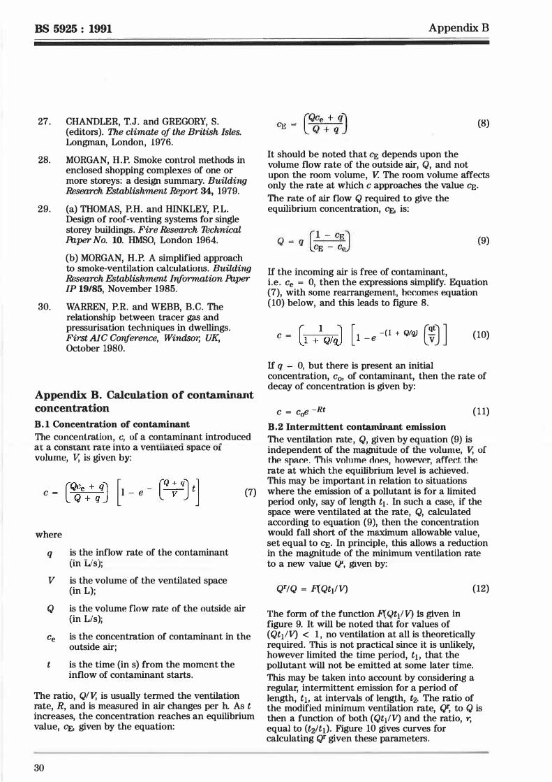
BS 5925 : 1991
27. CHANDLER, T.J. and GREGORY, S. (editors). The climate of the British Isi,es. Longman, London, 1976.
28. MORGAN, H.P. Smoke control methods in enclosed shopping complexes of one or more storeys: a design summary. Building Research Establishment Report 34, 1979.
29. (a) THOMAS, P.H. and HINKLEY, P.L. Design of roof-venting systems for single storey buildings. Fire Research Thchnical fuper No. 10. HMSO, London 1964.
(b) MORGAN, H.P. A simplified approach to smoke-ventilation calculations. Bu'ilding Research Establishment Information fuper IP 19/85, November 1985.
30. WARREN, P.R. and WEBB, B.C. The relationship between tracer gas and pressurisation techniques in dwellings. First AIC Conference, Windsor, UK, October 1980.
Appendix B. Calculation of contaminant concentration
B. 1 Concentration of contaminant The concentration, c, of a contaminant introduced at a constant rate into a ventiiateri space of volume, V, is given by:
c = [�\+ qqJ [1 - e - [Q
; qJ t] (7)
where
q is the inflow rate of the contaminant (in L/s);
V is the volume of the ventilated space (in L);
Q is the volume flow rate of the outside air (in Lis);
Ce is the concentration of contaminant in the outside air;
t is the time (in s) from the moment the inflow of contaminant starts.
The ratio, QIV, is usually termed the ventilation rate, R, and is measured in air changes per h. As t increases, the concentration reaches an equilibrium value, Cf;, given by the equation:
30
Appendix B
(QCe + qi CE = Q + q j (8)
It should be noted that Cf; depends upon the volume flow rate of the outside air, Q, and not upon the room volume, V. The room volume affects only the rate at which c approaches the value Cf;. The rate of air flow Q required to give the equilibrium concentration, Cf;, is:
Q = q r1 - CEJ LCE - c;J
If the incoming air is free of contaminant,
(9)
i.e. Ce = 0, then the expressions simplify. Equation (7), with some rearrangement, hec.omes equation (10) below, and this leads to figure 8.
c = [l /Q/� [1 - e -(I + Qlq) (*J J (10)
If q - 0, but there is present an initial concentration, c0, of contaminant, then the rate of decay of concentration is given by:
c = c0e -Rt ( 11)
B.2 Intermittent contaminant emission The ventilation rate, Q, given by equation (9) is independent of the magnitude of the volume, V, of thP. spar.P. . This volnmP. nm�s, hoWP.VP.T1 aff P.c.t the rate at which the equilibrium level is achieved. This may be important in relation to situations where the emission of a pollutant is for a limited period only, say of length t1 . In such a case, if the space were ventilated at the rate, Q, calculated according to equation (9), then the concentration would fall short of the maximum allowable value, set equal to CE· In principle, this allows a reduction in the magnitude of the minimum ventilation rate to a new value CJ'-, given t>y:
QTIQ = }lQt1IV) (12)
The form of the function F( Qt1! V) is given in figure 9. It will be noted that for values of (Qt1!V) < 1 , no ventilation at all is theoretically required. This is not practical since it is unlikely, however limited the time period, t1 , that the pollutant will not be emitted at some later time. This may be taken into account by considering a regular, intermittent emission for a period of length, ti, at intervals of length, 0,. The ratio of the modified minimum ventilation rate, QT, to Q is then a function of both (Qt1IV) and the ratio, r, equal to (t2lt1). Figure 10 gives curves for calculating QT given these parameters.
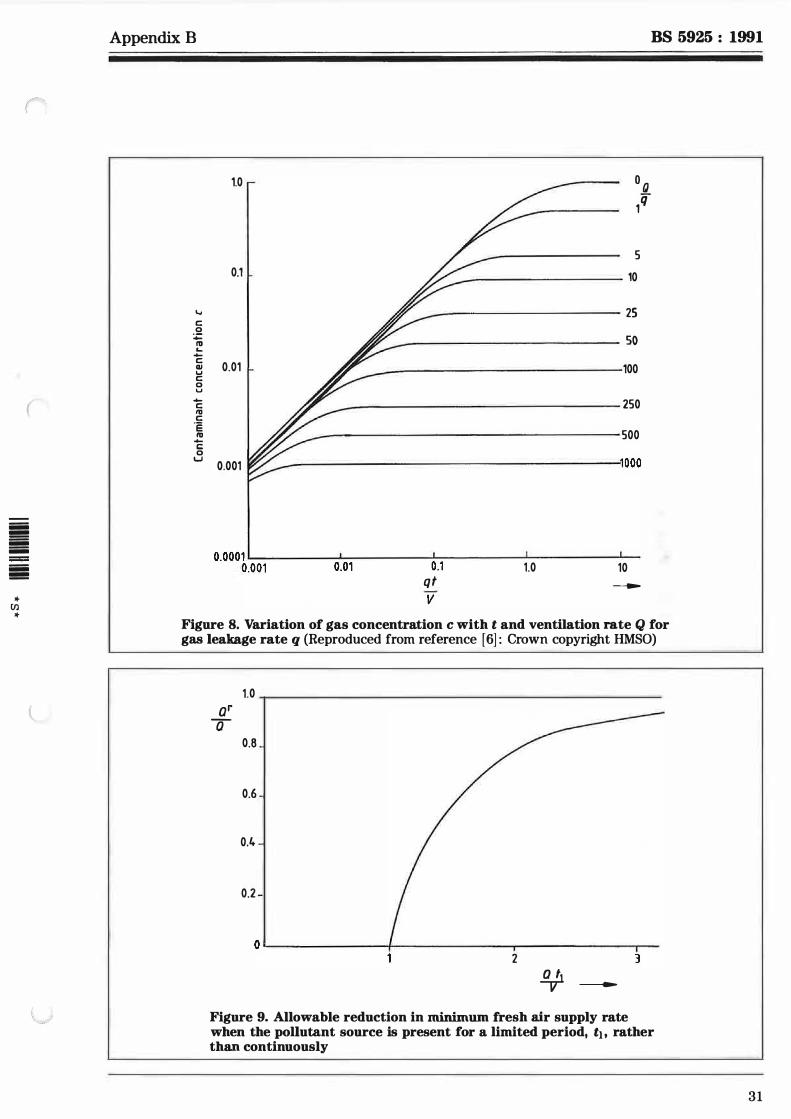
iiiii !!!!! iiiii iiiii iiiii !!!!!
... {/)
...
Appendix B BS 5925 : 1991
.... c 0 :;::: "' ... -c GI u c 0 u -c I'll c ·e ID -c 0 '-'
1.0 r --- O Q
,rr
5 0.1 L /� 10
I ff 25
I /ff so 0.01 I- /r 100
I //' 250
I /// 500
0.001 W"/ 1000
0.0001 .__-------:'�----.l-----.l.-----.J.__ 0.001 0.01 0.1 1.0 10
qt ---v
Figure 8. Variation of gas concentration c with t and ventilation rate Q for gas leakage rate q (Reproduced from reference [ 6] : Crown copyright HMSO)
1.0 ar
a 0.8
0.6
0.4
0.2 -
0'--------1--------r--------r--2 3
!!Ji ---Figure 9. Allowable reduction in minimum fresh air supply rate when the pollutant source is present for a limited period, th rather than continuously
31
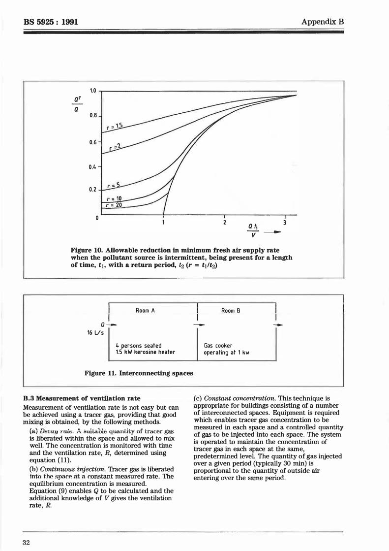
BS 5925 : 1991 Appendix B
1.0 ------------------------ar
a 0.8
0.6
0.4
0.2
0 2 a t,
v 3
-
Figure 10. Allowable reduction in minimum fresh air supply rate when the pollutant source is intermittent, being present for a length of time, t1, with a return period, t2 (r = t1/t2)
a --16 Us
Room A
4 persons seated 1.5 kW kerosine heater
Figure 11. Interconnecting spaces
B.3 Measurement of ventilation rate Measurement of ventilation rate is not easy but can be achieved using a tracer gas, providing that good mixing is obtained, by the following methods.
(a) Decay rate. A suitable quantity of tracer gas is liberated within the space and allowed to mix well. The concentration is monitored with time and the ventilation rate, R, determined using equation (11).
(b) Continuous injection. Tracer gas is liberated into the space at a constant measured rate. The equilibrium concentration is measured. Equation (9) enables Q to be calculated and the additional knowledge of V gives the ventilation rate, R.
32
Room B
---
Gas cooker operating at 1 kw
--
(c) Constant concentration. This technique is appropriate for buildings consisting of a number of interconnected spaces. Equipment is required which enables tracer gas concentration to be measured in each space and a controlled quantity of gas to be irJected into each space. The system is operated to maintain the concentration of tracer gas in each space at the same, predetermined level. The quantity of gas iajected over a given period (typically 30 min) is proportional to the quantity of outside air entering over the same period.
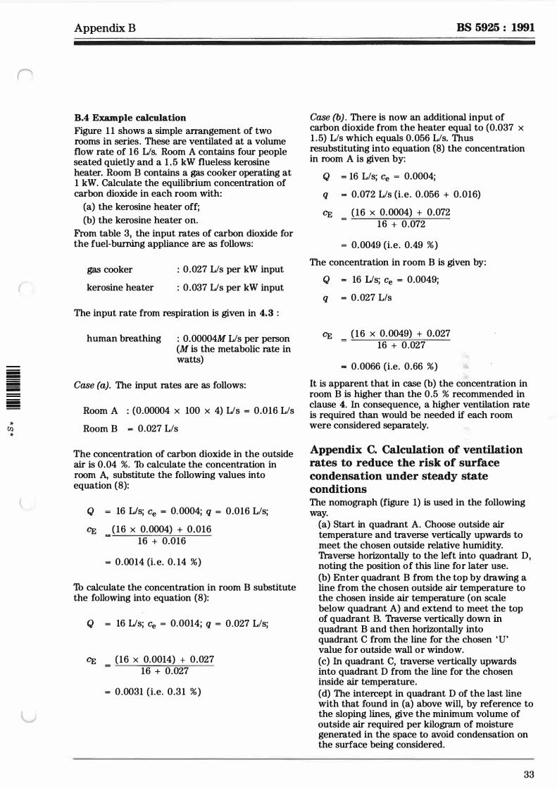
('
(
iiiii !!!!! iiiii iiiii iiiii !!!!!
>t (}) >t
Appendix B
B.4 Example calculation Figure 11 shows a simple arrangement of two rooms in series. These are ventilated at a volume flow rate of 16 Lis. Room A contains four people seated quietly and a 1 . 5 kW flueless kerosine heater. Room B contains a gas cooker operating at 1 kW. Calculate the equilibrium concentration of carbon dioxide in each room with:
(a) the kerosine heater off; (b) the kerosine heater on.
From table 3, the input rates of carbon dioxide for the fuel-burning appliance are as follows:
gas cooker
kerosine heater
: 0.027 Lis per kW input
: 0.037 Lis per kW input
The input rate from respiration is given in 4.3 :
human breathing : 0.00004M Lis per person (M is the metabolic rate in watts)
Case (a). The input rates are as follows:
Room A : (0.00004 x 100 x 4) Lis = 0.016 Lis
Room B "" 0.027 Lis
The concentration of carbon dioxide in the outside air is 0.04 %. Th calculate the concentration in room A, substitute the following values into equation (8):
Q = 16 L/s; Ce = 0.0004; q = 0.016 Lis;
CE (16 x 0.0004) + 0.016 16 + 0.016
= 0.0014 (i. e. 0. 14 %)
'lb calculate the concentration in room B substitute the following into equation (8):
Q = 16 Lis; Ce = 0.0014; q = 0.027 Lis;
CE (16 x 0.0014) + 0.027 16 + 0.027
= 0.0031 (i.e. 0.31 %)
BS 5925 : 1991
Case (b) . There is now an additional input of carbon dioxide from the heater equal to (0.037 x 1 .5) Lis which equals 0.056 Lis. Thus resubstituting into equation (8) the concentration in room A is given by:
Q = 16 Lis; Ce = 0.0004;
q = 0.072 Lis (i.e. 0.056 + 0.016)
CE (16 x 0.0004) + 0.072 16 + 0.072
= 0.0049 (i.e. 0.49 %) The concentration in room B is given by:
Q - 16 Lis; Ce = 0.0049;
q = 0.027 L/s
CE (16 x 0.0049) + 0.027 16 + 0.027
= 0.0066 (i.e. 0.66 %) It is apparent that in case (b) the concentration in room B is higher than the 0.5 % recommended in clause 4. In consequence, a higher ventilation rate is required than would be needed if each room were considered separately.
Appendix C. Calculation of ventilation rates to reduce the risk of surface condensation under steady state conditions The nomograph (figure 1) is used in the following way.
(a) Start in quadrant A. Choose outside air temperature and traverse vertically upwards to meet the chosen outside relative humidity. Traverse horizontally to the left into quadrant D, noting the position of this line for later use. (b) Enter quadrant B from the top by drawing a line from the chosen outside air temperature to the chosen inside air temperature (on scale below quadrant A) and extend to meet the top of quadrant B. Traverse vertically down in quadrant B and then horizontally into quadrant C from the line for the chosen 'U' value for outside wall or window. (c) In quadrant C, traverse vertically upwards into quadrant D from the line for the chosen inside air temperature. ( d) The intercept in quadrant D of the last line with that found in (a) above will, by reference to the sloping lines, give the minimum volume of outside air required per kilogram of moisture generated in the space to avoid condensation on the surface being considered.
33
BS 5925 : 1991
Appendix D. Determination of ventilation requirements
D.1 Example Consider a domestic living room:
Size:
Occupancy:
Heating:
Internal conditions:
External conditions
dimension 3.5 m by 4 m by 2.3 m hig.lt floor area 14 m2 volume 32 m3
six adults
metabolic heat production 125 W each
respiratory moisture 0.05 kg/h each
smoking three cigarettes per h
1 kW flueless kerosine heater
20 °C 60 % r.h. (8.8 g/kg dry air)
(a) 5 °C 95 % r.h. (5 . 2 g/kg dry air) 0.04 % C02, no other
contaminants
(b) 10 °C 90 % r.h. (6.9 g/kg dry air) ,..,,... . ( " \ vv2 i:1:i u1 \.i:1J
D.2 Required ventilation rates for different purposes
34
(a) Control of carbon dioxide Sources of carbon dioxide are:
(1) human respiration; and (2) operation of the kerosine heater.
� - -- ! ,_,_,: ..,. _ _ . _,.. .&-.-.-- •1... -... .... .......... .. -................... ,_ _.,... - '"' J. .& lC CU�.&UJ.l .I d.LC� J.J.VUl LJ.n;.::n:; i:'.>VUJ.\,..-.;:;� a.&.c °" follows: (i) respiration (from table 1): 6 x 125 x 40 x 10- 6 = 0.03 L/s (ii) kerosine heater (from table 3) : 0.034 Lis This gives a total of 0.064 Us Th.king 0.5 % as the desired maximum concentration, then substitution, as follows, into equation (9) leads to a required outside air rate, Q:
r: 1 - 0.0004 J Q - 0.064 l0.005 - 0.0004
Appendix D
Required ventilation rate for C02 is 13.9 Us. (b) Control of body odour On the basis of the 8 Us per person the required ventilation rate is 48 Us. (c) Control of tobacco smoke If control of odour is taken as the criterion, then on the basis of a smoking rate per h the required ventilation is 360 m3/h which is equal to 100 Us. ( d) Control of sulphur dioxide From table 3, the required flow rate to ensure that sulphur dioxide level does not exceed 1 .0 ppm is 6.0 Us. (e) Control of humidity Sources of water vapour are:
(1) human respiration; and (2) the kerosine heater.
Emission rates are as follows: (i) Respiration: 6 x 0.05 kg/h = 0.30 kg/h (ii) Kerosine heater: 0. 10 kg/h Thus, total water vapour emission rate is 0.40 kg/h The required flow rate may be obtained by substitution in equation (9), taking care to ensure that the units for the various quantities are compatible. i .e. water vapour concentration is generally expn�ssed in terms of g/kg dry air. Fbr ca.se (a):
Ce = 5.2 g/kg; CE = 8.8 g/kg Then required outside air supply rate (kg/h) is given by:
fJ = u.4U ill - u.uuoiJttu.uutsts - u.uuniJj =
110.5 kg.lb Th.king the density of dry air at 20 °C as 1 . 2 kg!m3, this gives a required ventilation rate of 25.5 L/s. For case (b):
Ce = 6.9 g/kg; CE = 8.8 g/kg Then required outside air supply rate (kg/h) is given by:
Q = 0.40 f( l - 0.0069)/(0.0088 - 0.0069)) =
209. l kg/h Tuking the density of dry air at 20 °C as 1 .2 kgtm3, this gives a required ventilation rate of 48.3 Us.
Summary The required ventilation rates for the range of possible criteria set out in appendix D may be summarized as follows.
(1) Carbon dioxide ( < 0.5 %(VIV)): 14 Us
(2) Body odour:
(3) Tubacco smoking (odour):
(4) Sulphur dioxide ( < LO Vppm):
(5) Water vapour ( < 60 % r.h.) for case (a): for case (b)
48 Us
100 Lis 6 Us
26 Us 48 Us
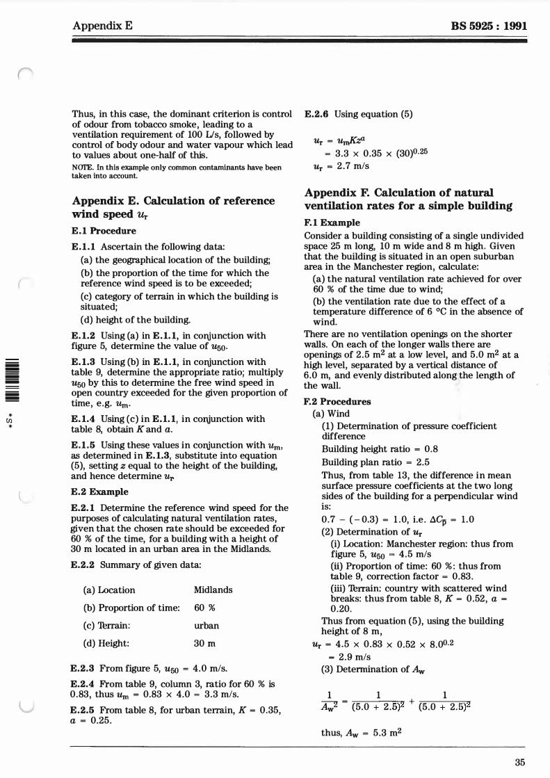
(
iiii � iiii iiii iiii �
* (/l
*
(
Appendix E
Thus, in this case, the dominant criterion is control of odour from tobacco smoke, leading to a ventilation requirement of 100 IJs, followed by control of body odour and water vapour which lead to values about one-half of this.
NCYl'E. In this example only common contaminants have been taken into account.
Appendix E. Calculation of reference wind speed Ur
E.1 Procedure
E.1.1 Ascertain the following data:
(a) the geographical location of the building;
(b) the proportion of the time for which the reference wind speed is to be exceeded;
(c) category of terrain in which the building is situated;
( d) height of the building.
E.1.2 Using (a) in E.1. 1, in conjunction with figure 5, determine the value of u50.
E.1.3 Using (b) in E.1.1, in conjunction with table 9, determine the appropriate ratio; multiply u50 by this to determine the free wind speed in open country exceeded for the given proportion of time, e.g. Um·
E.1.4 Using (c) in E.1. 1, in cmtjunction with table 8, obtain K and a.
E.1.5 Using these values in cortjunction with Um, as determined in E.1.3, substitute into equation (5), setting z equal to the height of the building, and hence determine Ur E.2 Example
E.2. 1 Determine the reference wind speed for the purposes of calculating natural ventilation rates, given that the chosen rate should be exceeded for 60 % of the time, for a building with a height of 30 m located in an urban area in the Midlands.
E.2.2 Summary of given data:
(a) Location Midlands
(b) Proportion of time: 60 % (c) Turrain:
(d) Height:
urban
30 m
E.2.3 From figure 5, u50 = 4.0 mis.
E.2.4 From table 9, column 3, ratio for 60 % is 0.83, thus Um = 0.83 x 4.0 = 3.3 mis.
E.2.5 From table 8, for urban terrain, K = 0.35, a = 0.25.
BS 5925 : 1991
E.2.6 Using equation (5)
Ur = uJ(:;!J = 3.3 x 0.35 x (30)0.25
Ur = 2 .7 mis
Appendix F. Calculation of natural ventilation rates for a simple building
F.1 Example Consider a building consisting of a single undivided space 25 m long, 10 m wide and 8 m high. Given that the building is situated in an open suburban area in the Manchester region, calculate:
(a) the natural ventilation rate achieved for over 60 % of the time due to wind;
(b) the ventilation rate due to the effect of a temperature difference of 6 °C in the absence of wind.
There are no ventilation openings on the shorter walls. On each of the longer walls there are openings of 2.5 m2 at a low level, and 5.0 m2 at a high level, separated by a vertical distance of 6.0 m, and evenly distributed along the length of the wall.
F.2 Procedures (a) Wind
(1) Determination of pressure coefficient difference
Building height ratio = 0.8 Building plan ratio = 2.5 Thus, from table 13, the difference in mean surface pressure coefficients at the two long sides of the building for a perpendicular wind is:
0. 7 - ( - 0.3) = 1 .0, i.e . .lC:p = 1 .0 (2) Determination of Ur
(i) Location: Manchester region: thus from figure 5, u50 = 4.5 mis
(ii) Proportion of time: 60 % : thus from table 9, correction factor = 0.83. {iii) Turrain: country with scattered wind breaks: thus from table 8, K = 0.52, a = 0.20.
Thus from equation (5), using the building height of 8 m,
Ur = 4.5 x 0.83 x 0.52 x 8.00.2 = 2.9 mis
(3) Determination of Aw
1 1 1 A""""2 = ( 2 5)2 + ( 5)2 Aw 5.0 + . 5.0 + 2.
thus, Aw = 5.3 m2
35
BS 5925 : 1991
36
(4) Determination of ventilation rate Using the formula in table 11 , section (a),
Qw = 0.61 x 5.3 x 2.9 x 1 .00.5 m3/s
Qw = 9.4 m3/s
The volume of the building is 25 m3 x 10 m3 x B m3, i.e. 2000 m3 Thus the air change rate is 3600 x 9.4/2000 = 17 air changes/h
Appendix E
(b) Tumperature difference From the information given: temperature difference = 6.0 °C; height between openings H1 = 6.0 m
1 1 1 Ab
2 =
(2. 5 + 2.5)2 + (5.0 + 5. 0)2
thus, Ab = 4.5 m2. 'Thking 0 = 300 K, and using the formula given in table 1 1 , section (b), � = 0.61 x 4.5 x (2 x 6 x 9.81 x 6 I 300)0.5 Qi, = 4.2 rn3/s. Thus, the air change rate is 3600 x 4.2/2000 - 7.6 air changes/h.
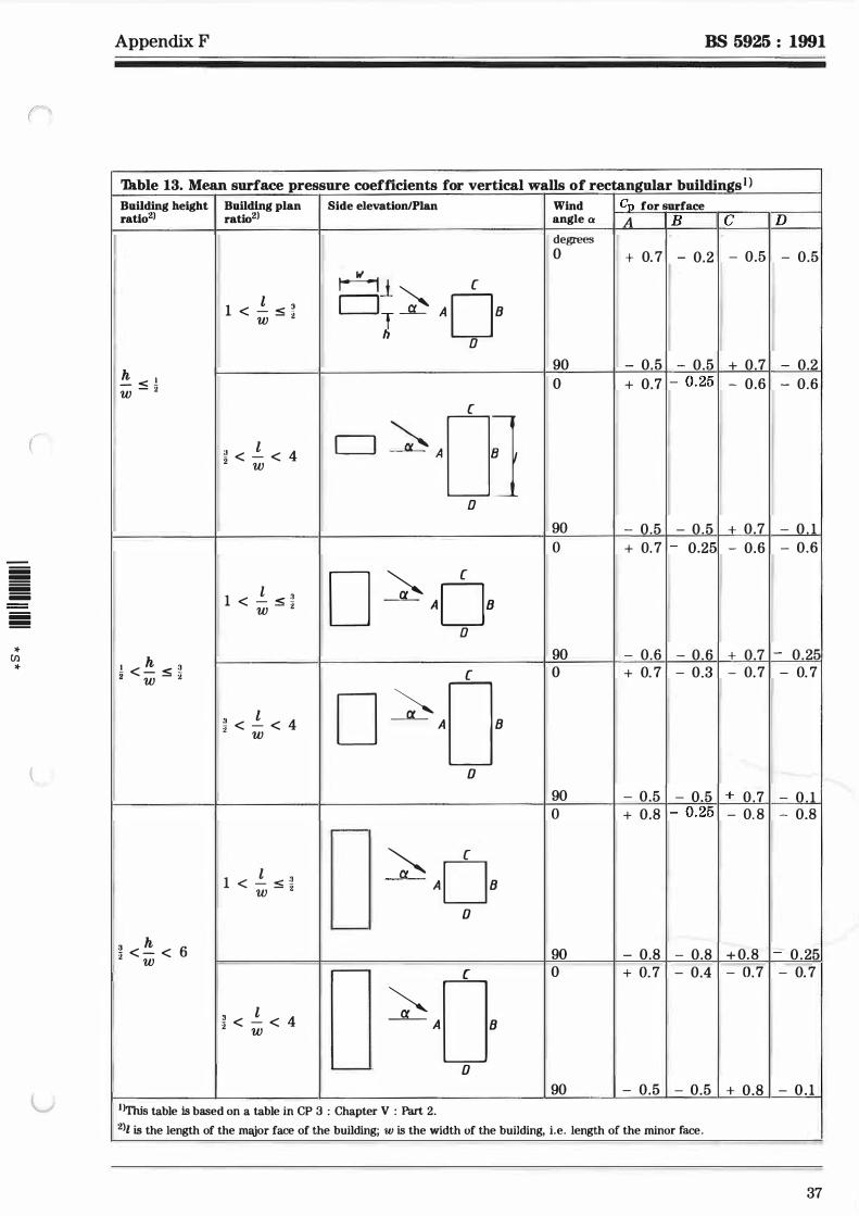
("
iiii !!!! iiii iiii iiii !!!!
* [/) *
(
Appendix F BS 5925 : 1991
'Th.hie 13. Mean surface pressure coefficients for vertical walls of rectangular buildings1 > Building height I Building plan ratio2l ratio2l
h - < ! w - 2
I h 2 < - < � w - i
3 h 6 2 < - < w
l 1 < - < ? w - 2
'.! < _!_ < 4 2 w
l 1 < - < � w - 2
� < _!_ < 4 w
l 1 < - < � w - 2
3 l 2 < - < 4 w
Side elevation/Plan
H1 CJ � I [
ADB D
CJ �AoJ D
D
[
� ADB D
[
o �AoB
0
---[
�ADB 0
'--
---
�AoB ..._______., 0
1l'fhis table ls based on a table in CP 3 : Chapter V : Part 2.
Wind angle a
degrees
0
90 0
Cn for surface
A I B I C D
+ 0. 7 I - 0.2 I - 0.5 I - 0.5
- 0.5 I - 0.5 I + 0.7 I - 0.2 + 0.7 I- 0.25 1 - 0.6 I - 0.6
90 I - 0.5 I - 0.5 I + 0.7 I - 0 . 1 o I + o. 7 I- 0.25 I - 0.6 I - 0.6
90 - 0.6 I - 0.6 I + 0.7 1 - 0.25 0 + o. 7 I - 0.3 I - o. 7 I - o. 7
90 I - 0.5 I - 0.5 I + 0 .7 I - 0 . 1 o I + 0.8 I- 0.25 1 - 0. 8 I - 0.8
90 - 0.8 I - 0.8 I + 0.8 I - 0 .25 0 + o. 7 I - 0.4 I - o. 7 I - 0. 7
90 I - 0.5 I - 0.5 I + 0.8 I - 0 . 1
2lt is the length of the major face of the building; w is the width of the building, i.e. length of the minor face.
37
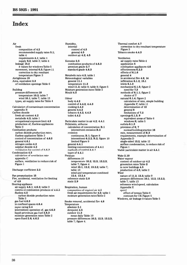
BS 5925 : 1991
Index
Air fresh
composition of 4.2 recommended supply rates 5.1; table 4 requirements 4.1; table 1 supply 6.2; table 3; table 4
leakage 15.2 k values for windows Tuble 5
movement, internal 6.3; figure 1 1 correction to dry resultant temperature Figure 3
Airtightness 15 Area, equivalent 2.3
of ventilation openings Thble 6 Building
pressure differences 10 temperature 10.2; table 7 wind 10. 1; table 7; table 13
types, air supply rates for Thble 4
Calculation of contaminant concentration appendix B
Carbon dioxide fresh air content 4.2 metabolic 4.3; table 1 occupational exposure limit 4.3 production of, flueless appliances Thble 3
Combustion products carbon dioxide produetion rates, flueless appliances Thble 3 control of concentration of 4.6.3 general 4.6.1 nitrojlen oxides 4.2 sulphur dioxide 4.2 .... �r.til:it!!Jr. f�!" ���!�! �f 1-�-�
Condensation 4. 5 eakulllt.inn nf vPnt.il:ition rnt.P appendix C surface, ventilation to reduce risk of Figure l
Discharge coefficient 2.2
Fan pressurization 15 Fire, accidental, ventilation for limiting
of 4.8 Heating appliance
air supply 4.6. 1; 4.6.2; table 3 control of combustion pro<iucis oi 4.o.;; flueless 4.5 ·
carbon dioxide production rates Thble 3
gas fuel 4.6.3 in confined spaces 4.6.4 iupuL rating 2.4 intermittent operation of, gas 4.6.3 liquid petroleum g;u; fuel 4.6.3 moisture generation rates Tuble 2 open-flued 2.6; 4.6.2
38
Humidity, internal
control of 4.5 general 4.5
outdoor air 4.2; 4.5
Kerosine 2.5 combustion products of 4.6.3 premium grade 2. 7 Standard grade 4.6.3
Metabolic rate 4.3; table 1 Meteorological variables
general 11.1 temperature 11.3 wind 11.2; table 8; table 9; figure 5
Moisture generation rates Thble 2 Mould 4.5
Odour body 4.4.2 control of 4.4.2; 4.4.3 cooking 4.4.2 general 4.4.2 tobacco 4.4.2; 4.4.3 toilet 4.4.2
Particulate matter in air 4.2; 4.4.1 Pollutants, airborne
calculation of concentration B. 1 intermittent emission B.2
P.mission continuous; B. l; figure 8 intermittent 6.2.2; 8.2; figure 10 limited Figure 9
general 4.4. 1 limiting concentrations of 4.4.1 !!!.""thtl(lq nf ront.ml 4_4_ 1 types of 4A. l
Pressure differences 10
temperat.urP. 10.2; 12.3; 13.2.3; table 7; figure 4 wind 10. 1; 12.2; 13.2.2; table 7 ; table 13 wind and temperature combined 12.4; 13.2.4
reference static 2.8 static 2.9
Respiration, human • • • ,. - -- ! _ _ _ .JI _ ! _ . ... CUJllIJU:SU.IUU UJ �A1J.Ut:U i1U. �.t.J
fresh air requirements for 4.3; table 1 moisture generation rates Thble 2
Smoke removal, accidental fire 4.8 Tumperature
absolute 2.1 dewpoint 4.5 outdoor 11.3
mean daily Tuble 10 pressure differences 10.2; 12.3; 13.2.3; table 7; figure 4.
Thermal comfort 4. 7 correction to dry resultant temperature Figure 3
Tubacco smoke 4.4.3
Ventilation air supply rates Thble 4 application 5 combustion appliances 4.6 effectiveness 6.2.3 effects of 6.1.6 general 4 in accidental fire 4.8; 14 infiltration 6.1.2; 15.1 inlets 6.1.3 mechanical 6. 1. 5; figure 2
need for 7.3 methods of 6. 1. 1; figure 2
choice of 7 natural 6. 1.4; figure 2
calculation of rate, simple building Appendix F; table 1 1 determination of 12 general 8 limitations of 7. 2
openings 6. 1.3; 9 equivalent areas of Thble 6 windows 9; table 5
outlets 6.1.3 provision of 6; 7
normal building practice 16 rate, measurement of B.3 requirements, example detennination of Appendix D single-sided 13.2; table 12 swface condensation, to reduce risk of Figure 1
ViahlP. particulate matter in air 4.4. 1
Wake 2 . 10 Water vapour
content of outdoor air 4.2 generation rates Tuble 2 in new buildings 4. 5 production of 4.5; table 2
Wind nature of 11.2; 13.3; table 9 pressure differences 10.1; 12.2; 13.2.2; table 7; table 13 reference wind speed, calculation Appendix E __ _ _ ... "�u
effect of terrain Thble 8 contours for UK Figure 5
Windows, air leakage k values Thble 5

()f: 'J/UV'JQ
)
-IC Ul -IC

'JU.'DJQ lit
r
iiiiii -iiiiii iiiiii -iiiiii !!!!!!!!
* C/l *
BS 5925 : 1991
Pnblication(s) referred to
BS 2869 BS 5250 BS 5410
BS 5440
BS 5588 BS 5643 BS 5720 BS 6100 BS 6230
BS 6375
BS 82071> BS 8303
CP 3
Fuel oils for non-marine use Code of practice for control of condensation in buildings Code of practice for oil firing Part 1 Installations up to 44 kW output capacity for space heating and hot water supply purposes Part 2 Installations of 44 kW and above output capacity for space heating, hot water and steam supply purposes Installation of flues and ventilation for gas appliances of rated input not exceeding 60 kW ( 1st, 2nd and 3rd family gases) Part 2 Specification for installation of ventilation for gas appliances Fire precautions in the design, construction and use of buildings Glossary of refrigeration, heating, ventilating and air-conditioning tenns Code of practice for mechanical ventilation and air conditioning in buildings Glossary of building and civil engineering tenns Specification for installation of gas-fired forced convection air heaters for commercial and industrial space heating of rated input exceeding 60 kW (2nd family gases) Performance of windows Part 1 Classification for weathertightness (including guidance on selection and specification) Code of practice for energy efficiency in buildings Code of practice for installation of domestic heating and cooking appliances burning solid mineral fuels Code of basic data for the design of buildings Chapter V Loading Part 2 Wind loads
l) Referred to in the foreword only
BS 5925 : 1991
BSI 2 Park Street London W1A 2BS
BSI Linford Wood Milton Keynes MK14 6LE
!}105- 8
BSI - British Standards Institution
BSI is the independent national body responsible for preparing British Standards. It presents the UK view on standards in Europe and at the international level. It is incorporated by Royal Charter.
Contract requirements
A British Standard does not purport to include all the necessary provisions of a contract. Users of British Standards are responsible for their correct application.
Revisions
British Standards are updated by amendment or revision. User8 of British Standards should make sure that they possess the latest amendments or editions.
Any person who finds an inaccuracy or ambiguity while using this British Standard should notify BSI without delay so that the matter may be investigated swiftly.
BSI offers members an individual updating service called PLUS which ensures that subscribers automatically receive the latest editions of standards.
Buying British St.andards
Orders for all British Standard publications should be addressed to the Sales Department at Milton Keynes.
Information on standards
RSI provides a wide range of information on natfonal, European and international standards through its Library, the Standardline Database, the BSI Information 'Thchnology Service (BITS) and its Tuchnical Help to Exporters Service. Contact Enquiry Section at Milton Keynes: 'Thl: 0908 221166.
Subscribing members of BSI are kept up to date with standards developments and receive substantial discounts on the purchase price of standards. For details of these and other benefits contact the Manager, Membership Development at Milton Keynes: Tul: 0908 220022.
Cupyrig}tl
Copyright subsists in all BSI publications. No part of this publication may be reproduced in any form without the prior permission in writing of BSI. This does not preclude the free use, in the course of implementing the standard, of details such as symbols and size, type or grade designations. Enquiries about copyright should be made to the Copyright Manager, Marketing at Milton Keynes.
BDB/2
iiiiiii !!!!!! iiiiiii iiiiiii iiiiiii !!!!!!
* Ul *
{'
• ==�=---.,.,,,,, ........ -
STANDARD S
Amendment No. 1 published and effective from 15 December 1995 to BS 5925 : 1991
Code of practice for ventilation principles and designing for natural ventilation
Correction
Clause 9. F1ow characteristics of openings
Delete equation (2) and substitute the following I
Q = C�(21lplp) 2 (2) AMD 8930/December 1995
9612 Product code 00628060
AMD 8930
B/640/2